Embed Size (px)
Citation preview
Fixed Station
Upgrades/Developments

N94"15601
MATERA LASER RANGING OBSERVATORY (MLRO), AN OVERVIEW
Thomas Varghese, Winfield Decker, Henry Crooks
Allied-Signal Aerospace CompanyBendix/CDSLR Network
Seabrook, Maryland 20706U.S.A.
Giuseppe Bianco
Agenzia Spaziale Italiana/Centro di Geodesia Spaziale
Matera, Italy
Abstracl;:
The Agenzia Spaziale Italiana (ASI) is currently under negotiation with the
Bendix Field Engineering Corporation (BFEC) of the Allied Signal Aerospace
Company (ASAC) to build a state-of-the-art laser ranging observatory for the
Centro di Geodesia Spaziale, in Matera, Italy. The contract calls for the
delivery of a system based on a 1.5 meter afocal Cassegrain astronomical
quality telescope with multiple ports to support a variety of experiments for
the future, with primary emphasis on laser ranging. Three focal planes, viz.
Cassegrain, Coude, and Nasmyth will be available for these experiments.The open,telescope system will be protected from dust and turbulence using
a specialized dome which will be part of the building facilities to be provided
by ASI. The fixed observatory facility will be partitioned into four areas for
locating the following: laser, transmit/receive optics, telescope/dome
enclosure, and the operations console. The optical tables and mount rest on
a common concrete pad for added mechanical stability. Provisions will be in
place for minimizing the effects of EMI, for obtaining maximum cleanliness
for high power laser and transmit optics, and for providing an ergonomic
environment fitting to a state-of-the-art multipurpose laboratory.
The system is currently designed to be highly modular and adaptable for
scaling or changes in technology. It is conceived to be a highly automated
system with superior performance specifications to any currently operational
system. Provisions are also made to adapt and accommodate changes that
are of significance during the course of design and integration.
ii-i
MLRO :An Overview
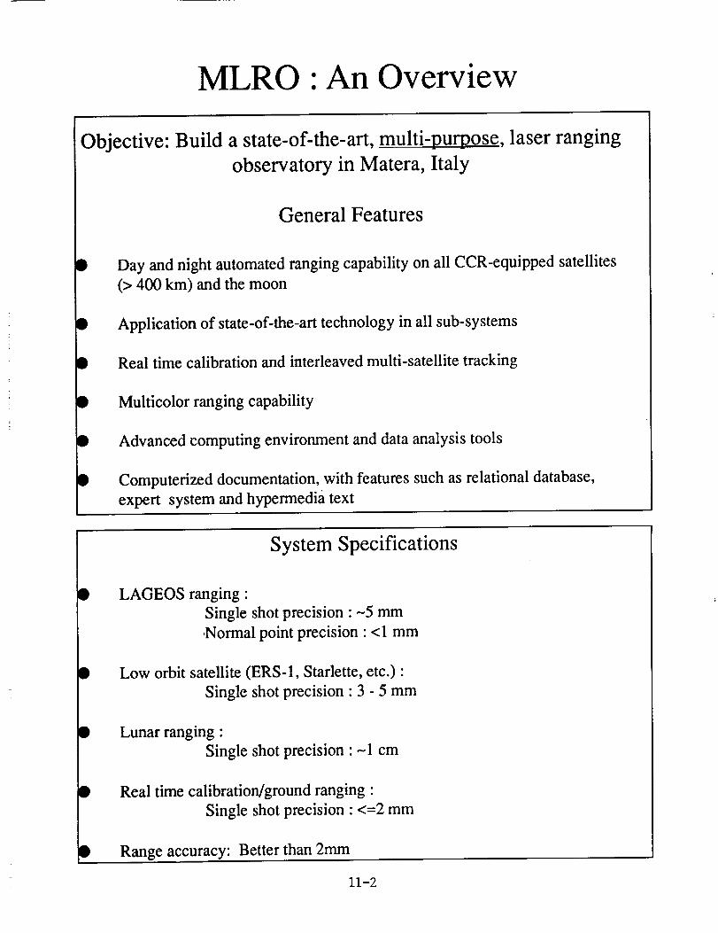
Objective: Build a state-of-the-art, multi-purpose, laser rangingobservatory in Matera, Italy
General Features
I Day and night automated ranging capability on all CCR-equipped satellites
(> 400 km) and the moon
• Application of state-of-the-art technology in all sub-systems
• Real time calibration and interleaved multi-satellite tracking
• Multicolor ranging capability
• Advanced computing environment and data analysis tools
• Computerized documentation, with features such as relational database,
expert system and hypermedia text
System Specifications
LAGEOS ranging"
Single shot precision • --5 mm
.Normal point precision • < 1 mm
Low orbit satellite (ERS-1, Starlette, etc.) •
Single shot precision • 3 - 5 mm
i
Lunar ranging •
Single shot precision • -1 cm
Real time calibration/ground ranging •
Single shot precision • <=2 mm
Range accuracy: Better than 2mm
11-2
MLRO :An Overview
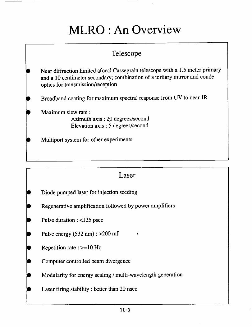
Telescope
Near diffraction limited afocal Cassegrain telescope with a 1.5 meter primary
and a 10 centimeter secondary; combination of a tertiary mirror and coude
optics for transmission/reception
Broadband coating for maximum spectral response from UV to near-IR
Maximum slew rate •
Azimuth axis • 20 degrees/second
Elevation axis • 5 degrees/second
Multiport system for other experiments
D
Laser
Diode pumped laser for injection seeding
Regenerative amplification followed by power amplifiers
Pulse duration : <125 psec
Pulse energy (532 nm): >200 rnJ
Repetition rate : >=10 Hz
Computer controlled beam divergence
Modularity for energy scaling / multi-wavelength generation
Laser firing stability : better than 20 nsec
11-3
MLRO :An Overview
D
D
t
D
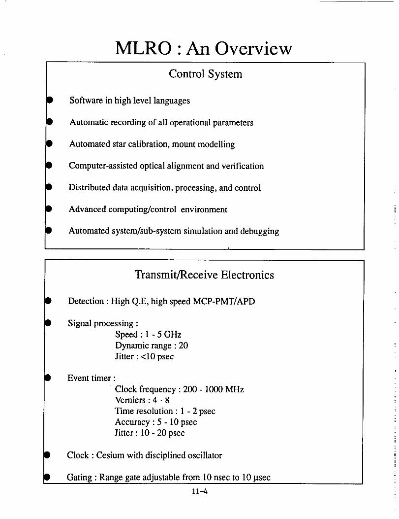
Control System
Software in high level languages
Automatic recording of all operational parameters
Automated star calibration, mount modelling
Computer-assisted optical alignment and verification
Distributed data acquisition, processing, and control
Advanced computing/control environment
Automated system/sub-system simulation and debugging
D
D
D
Transmit/Receive Electronics
Detection" High Q.E, high speed MCP-PMT/APD
Signal processing :
Speed : 1 - 5 GHz
Dynamic range : 20
Jitter : <10 psec
Event timer
Clock frequency : 200 - 1000 MHzVerniers : 4 - 8
Time resolution : 1 - 2 psec
Accuracy : 5 - 10 psec
Jitter : 10 - 20 psec
Clock • Cesium with disciplined oscillator
Gating • Range gate adjustable from 10 nsec to 10 _tsec
11-4
MLRO :An Overview
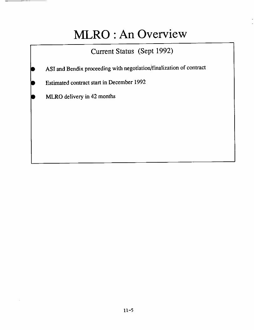
Current Status (Sept 1992)
D
I
ASI and Bendix proceeding with negotiation]finalization of contract
Estimated contract start in December 1992
• MLRO delivery in 42 months
11-5
' 94-15602
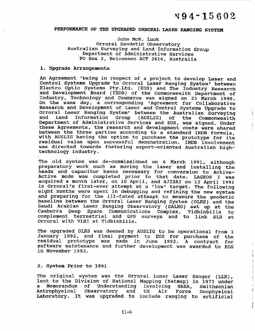
PERFORMANCE OF THE UPGRADED ORRORAL LASER RANGING SYSTEM
John McK. Luck
Orroral Geodetic Observatory
Australian Surveying and Land Information GroupDepartment of Administrative Services
PO Box 2, Belconnen ACT 2616, Australia
i. Upgrade Arrangements
An Agreement "being in respect of a project to develop Laser and
Control Systems Upgrade to Orroral Laser Ranging System" between
Electro Optic Systems Pty. Ltd. (EOS) and The Industry Research
and Development Board (IRDB) of the Commonwealth Department of
Industry, Technology and Commerce was signed on 23 March 1990.
On the same day, a corresponding 'Agreement for Collaborative
Research and Development of Laser and Control Systems Upgrade to
Orroral Laser Ranging System' between the Australian Surveying
and Land Information Group (AUSLIG) of the Commonwealth
Department of Administrative Services and EOS, was signed. Under
these Agreements, the research and development costs were shared
between the three parties according to a standard IRDB formula,
with AUSLIG having the option to purchase the prototype for itsresidual value upon successful demonstration. IRDB involvement
was directed towards fostering export-oriented Australian high-technology industry.
The old system was de-commissioned on 6 March 1991, although
preparatory work such as moving the laser and installing theheads and capacitor banks necessary for conversion to Active-
Active mode was completed prior to that date. LAGEOS I was
acquired a month later, on i0 April, and AJISAI on 12 April 1991
in Orroral's first-ever attempt at a 'low' target. The following
eight months were spent in debugging and refining the new system
and preparing for the ill-fated attempt to measure the geodetic
baseline between the Orroral Laser Ranging System (OLRS) and the
Saudi Arabian Laser Ranging Observatory (SALRO) set up at the
Camberra Deep Space Communications Complex, Tidbinbilla to
complement terrestrial and GPS surveys and to link SLR atOrroral with VLBI at Tidbinbilla.
The upgraded OLRS was deemed by AUSLIG to be operational from 1
January 1992, and final payment to EOS for purchase of the
residual prototype was made in June 1992. A contract for
software maintenance and further development was awarded to EOSin November 1992.
2. System Prior to 1991
The original system was the Orroral Lunar Laser Ranger (LLR),
lent to the Division of National Mapping (Natmap) in 1973 under
a Memorandum of Understanding involving NASA, Smithsonian
Astrophysical Observatory and US Air Force Geophysical
Laboratory. It was upgraded to include ranging to artificial
11-6
satellites under a contract from NASA signed in 1981, the firstreturns from LAGEOS-I being acquired in mid 1984. Some verifiedreturns from the moon were received in 1985, and ranging toETALON I & II started in 1990. It was not really possible toexpect results for two-way ranges less than 35 milliseconds,which is one of the main reasons for embarking on the upgradebeing described here.
Note : Natmap was merged with another Commonwealth agency inAugust 1987 to form AUSLIG.
DOME : The 9 metre diameter hemispherical dome by Ash Domes ofPlainfield,IL was installed atop the original cylindricalObservatory building in 1973. Its AC motors for rotation duringobserving were manually controlled by a Left-Off-Right lever.
TELESCOPE : 1.5 metre aperture Ritchey-Chretien reflectingtelescope, optics by University of Arizona. The tailpiece at the
Cassegrain focus carries an eyepiece mounted on an X-Y stage forstar observations and to facilitate offset guiding for lunar
ranging.
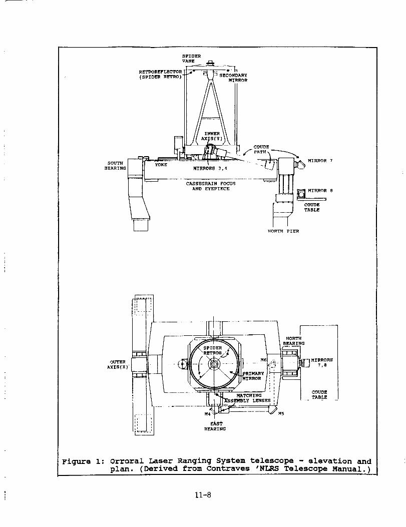
The telescope is used both for transmitting and for receiving.
It is depicted in figure i.
TELESCOPE MOUNT : The telescope tube is by Astro Mechanics of
Austin,TX. The original equatorial mount was replaced in 1981-2
by an X-Y ("alt over alt") mount by Contraves, and a Coude Pathand the Contraves MPACS drive and readout systems were added.
The drive accuracy is better than 0.002 degrees and encoder
resolution is 0.0001 degrees.
An interface/controller was built, and all interface drivers and
control and mount modelling software were written, by Natmap.
COUD_ PATH : The Coude path incorporates a Matching Assembly
consisting of two lenses whose combined focal point coincides
with the focal point of the telescope. These lenses are in the
East bearing of the telescope's inner axis. The Coude path
connects the telescope with the laser, transmitter and receiver
assemblies which are mounted on Newport optical benches in
environmentally stable rooms. A Times 5 Beam expander by Special
optics,NJ on the Coude bench expands the transmitted beam prior
to injection to the telescope through mirrors in the North
bearing.
TRANSMIT/RECEIVE ASSEMBLY (T/R) : A rotating aluminized mirror
with two holes in it, co-rotating 'dogbone' holding two ND
filters and CAMAC-controlled stepping motors constituted the T/R
assembly purchased from McDonald Observatory,TX in 1983. Laser
firing was triggered by optically sensed notches in the rim of
the rotating mirror.
The mirror was replaced in 1987 by an 'Appler mirror" in which
the holes were just glass left uncoated (glass-hole), and which
permitted positive, unambiguous ranging to a ground target and,
11-7
SOUTH
BEARING
SPIDER
VANE
" - I _- ----_ ROt
COUDE
MIRRORS 3 , 4 ._._
___ ANDE_EPI,._E _W HYRROR 8I
COUDE
TABLE
_ORTH PIER
Figure 1: Orroral Laser Ranging System telescope - elevation and
plan. (Derived from Contraves 'NLRS Telescope Manual.)
11-8
for real-time internal calibrations, to geodetically accessible
retro-reflectors placed on the spider vanes holding the
telescope's secondary mirror.
The interface was controlled by the CAMAC bus system, and driver
and high-level software was written by Natmap in collaboration
with the University of Texas.
RECEIVER/DETECTOR : A light-tight box containing a turret of 5
pinholes (spatial filters), a turret with a i0 A ° filter and a
hole, focussing optics and detector mount was provided by
McDonald Observatory. The detector mount was replaceable by an
eyepiece for star alignments.
The detector was an RCA 31034A PMT until 1986, when the first of
a series of ITT F4129f z-plate MCP PMTs was installed.
LASER : A Quantel YG 402 DP Nd:YAG laser frequency doubled to
532nm output wavelength was purchased as part of the 1981-3
upgrade. Its Q-switching and pulse slicing were accomplished
passively, the mode locking being active/passive. Two amplifierscombined to produce in excess of 250mJ per pulse at ten pulses
per second when needed. The pulse slicer was replaced by a
Quantel solid-state slicer model SPS411 in 1987.
The laser was removed from its Quantel plate in the Coude room
and relocated to an RF-shielded room one floor lower in the
Observatory building in August 1990. Its components were bolted
directly to a Newport optical table.
[The original Hughes 6943A ° ruby laser of the Orroral LLR priorto 1981 was bolted to the side of the telescope tube.]
LASER RANGING CONTROLLER (LRC) : This main interface/controller
was designed and built by Natmap. It set windows and gates,
controlled laser firing, and managed the epoch timing system.
EPOCH TIMING SYSTEM : Range measurements were accomplished by
measuring the "epoch" (time of day) of separate events, rather
than depending upon a Time Interval Counter. The LRC time base
was driven by a high spectral purity Oscilloquartz 2200 quartz
frequency standard at 10MHz, and its clock synchronised at the
start of each pass to an external Hewlett-Packard caesium beam
frequency standard whose own clock was kept within 1 microsecondof UTC. The LRC Clock was used to time tag events to i00
nanosecond resolution.
Each laser shot produces at least three events to be time
tagged: start diode pulse, internal calibration pulse from
MCP/PMT, and one or more satellite returns from MCP/PMT (the
quest to detect more than one 'satellite' return per shot was
abandoned in the mid-1980's). The epoch timing system philosophy
theoretically enables many events to be recorded per shot using
identical equipment, limited only by instrumental reset/read
times.
11-9
Two channels were used in practise to obtain fine resolution,one for start diode and one for MCP/PMT. Each comprised aseparate channel of the Tennelec 454 Quad Constant FractionDiscriminator (CFD), a LeCroy 4202A Time to Digital Converter(TDC), and a pair of 8-channel LeCroy 2228A TDCs as vernierscovering different 50ns sections. The 8 78-picosecond resolutionchannels of each 2228A were majority voted and meaned to improveresolution to about 28ps. A standard calibration routine was runwith each pass to relate the intrinsic 2228A delays to eachother, with the scale factors being calibrated periodicallyagainst the 4202A TDCs.
All TDCs were read via the CAMACbus system. Software for thesetasks was written by Natmap.
RECEIVE ENERGY MONITOR : A LeCroy 2249A Analog-to-Digital
Converter (ADC) ('charge digitiser') was installed on the MCP
line in March 1990. It is controlled and read through the CAMAC
bus system, and is gated by the 'AND' of the range gate window
and of the discriminator output pulse delayed appropriately. Its
input signal is amplified by a Stanford Research SR440.
OPERATING SOFTWARE : Apart from the lunar prediction package
based on EULER and the satellite prediction package based on
IRVINT, which were imported with the aid of Randall L. Ricklefs,
all interface drivers, control and operations software,
predictions, post-processing, mount modelling, simulation and
test software was written by Natmap.
SYSTEM CALIBRATION : Until the end of 1987, the internal
calibration pulse was picked off each transmitted laser pulse by
a minutely reflecting 'feedback plate' in the T/R box and fed to
the MCP/PMT through ND filters in the co-rotating 'dogbone'. The
optical and electronic delays between this feedback plate and
the epoch timing system were thus well calibrated, but the delay
between the feedback plate and the system reference point was
not well known, so it was not possible to assess system accuracy
properly as it was found impossible to measure or even estimate
the length of the convoluted Coude path (with its five
refracting elements as added complications) to better than 10cm.
The advent of the 'Appler mirror' in 1987 made it possible to
range to the 'Spider Retros' simultaneously with distant
targets. The effective reflection points of the retro-reflectors
were related to the instrumental reference point and external
survey marks early in 1988 with 3mm accuracy by precise survey,
enabling accurate correction constants to be calculated.
A ground target was installed at a distance of l.lkm across a
valley in November 1987, and surveyed in along with 'Spider
Retros'. A session of ranging to this target accompanied each
LAGEOS-I pass, and provided a check on the accuracy of the
correction constants referred to above. It is also invaluable
for assessing such things as the effect of signal strength on
range accuracy and the actual precision obtainable at any given
time.
II-i0
3. Elements of the Upgrade
DOME : Automated rotation was provided through hardware and
interface controllers. Two DC variable-speed motors were
installed in 1991 and new variable-speed controller, interface
and software are now under development.
TELESCOPE and COUDE PATH : Not affected by the upgrade.
TELESCOPE DRIVE : A new interface/controller for the MPACS, and
corresponding interface driver and high-level software, were
provided, as were two new handpaddles with their interface,controller and driver.
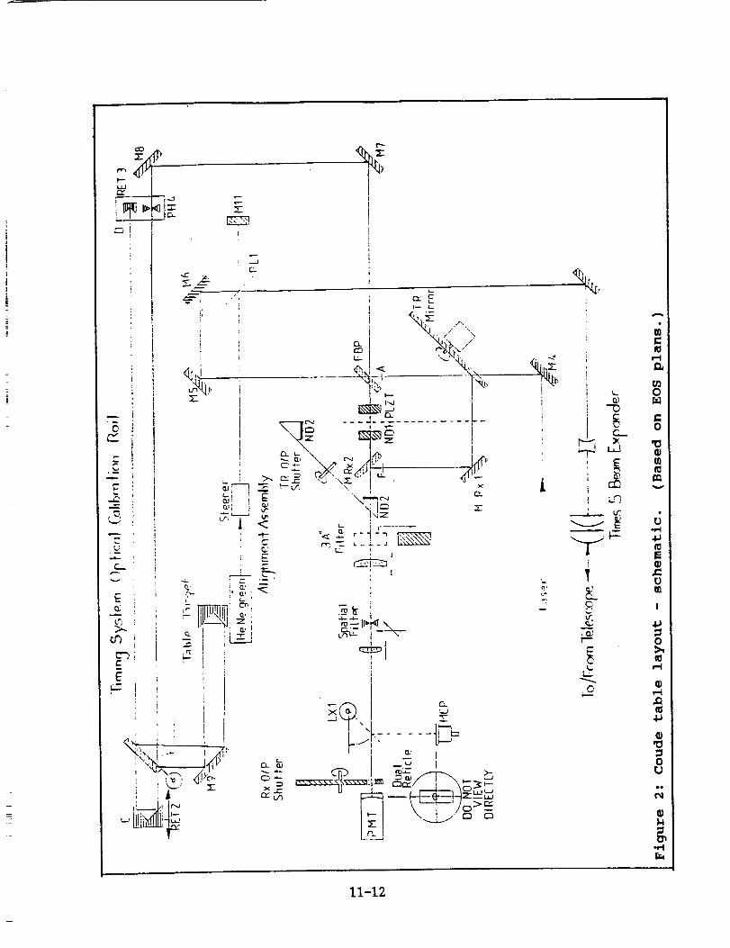
TRANSMIT/RECEIVE ASSEMBLY : A completely new box was provided
(figures 2,3). The T/R mirror has two genuine holes, and is
connected to the co-rotating 'dogbone' by a shaft incorporating
a clutch unit. Rotation rates up to 20 revs/second are possible,
and are controlled directly from the MRCS. Laser firing is
triggered by notches on the T/R mirror rim as before. Laser fire
commands may be inhibited through a 'divide by' facility so that
only every first, second, third or fourth notch actually causesa shot.
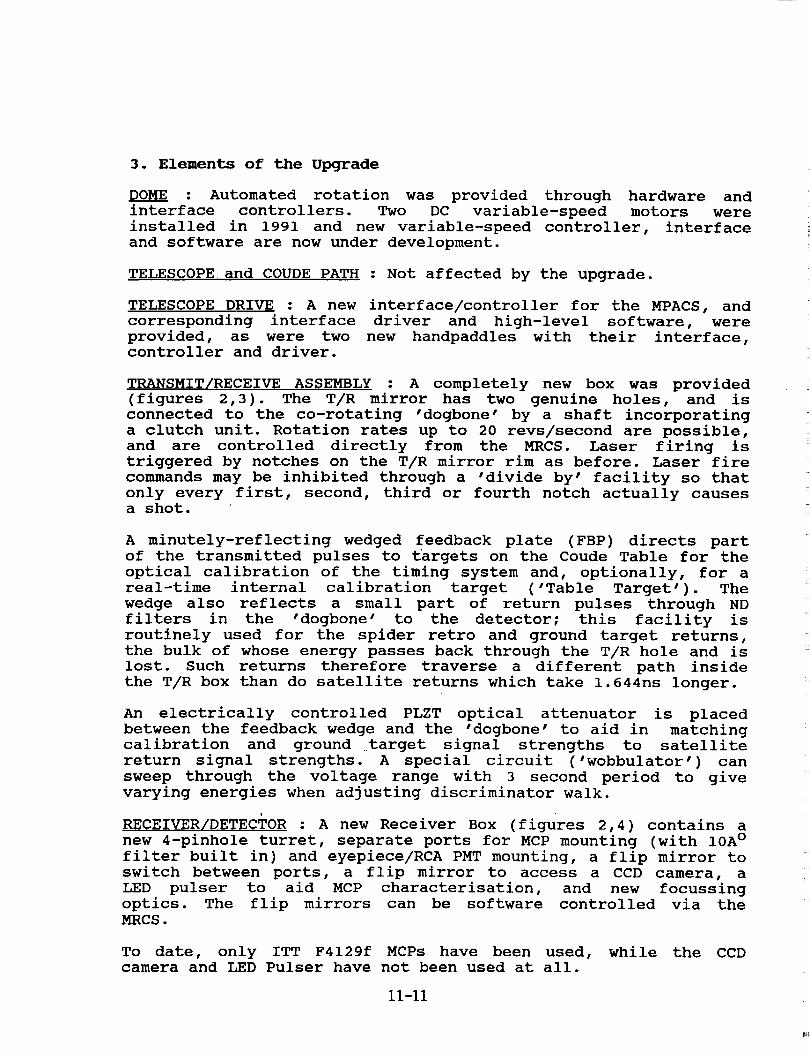
A minutely-reflecting wedged feedback plate (FBP) directs part
of the transmitted pulses to targets on the Coude Table for the
optical calibration of the timing system and, optionally, for a
real-time internal calibration target ('Table Target'). The
wedge also reflects a small part of return pulses through ND
filters in the 'dogbone' to the detector; this facility is
routinely used for the spider retro and ground target returns,
the bulk of whose energy passes back through the T/R hole and is
lost. Such returns therefore traverse a different path inside
the T/R box than do satellite returns which take 1.644ns longer.
An electrically controlled PLZT optical attenuator is placed
between the feedback wedge and the 'dogbone' to aid in matching
calibration and ground target signal strengths to satellite
return signal strengths. A special circuit ('wobbulator') can
sweep through the voltage range with 3 second period to give
varying energies when adjusting discriminator walk.
RECEIVER/DETECTOR : A new Receiver Box (figures 2,4) contains a
new 4-pinhole turret, separate ports for MCP mounting (with 10A °
filter built in) and eyepiece/RCA PMT mounting, a flip mirror to
switch between ports, a flip mirror to access a CCD camera, a
LED pulser to aid MCP characterisation, and new focussing
optics. The flip mirrors can be software controlled via theMRCS.
To date, only ITT F4129f MCPs have been used, while the CCDcamera and LED Pulser have not been used at all.
II-Ii
0
,,.<
Z
a..
t-..-
1
• i
r '-._J
f: m
,,_u "_-"_ ill-
'%'-
P
_A, -
,---..--
," _,_li_ o,ii.,,_'",_ 7 I
< "%%
"i_ t= =
,I",1 < i,C p-) ":_ L__---,
q
' I
_ I-'-1 1
",! I_-3.._
1 -" '
"_ [==_ _-_--_-L.>_-
I_#.j \'-AJ' _'
,.r"
c_
,... ,_
i
L"3,
i
I'"
b
.O
A
,--4
O
0
rj
0
0
M
11-12
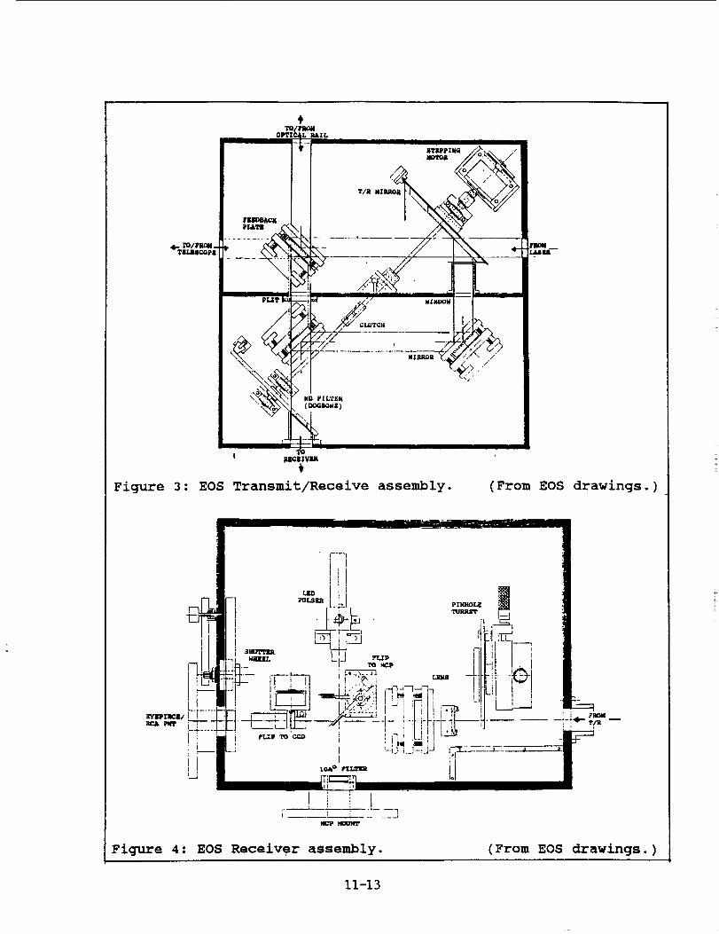
Figure 3 : EOS Transmit/Receive assembly.
I
Figure 4: EOS Receiver assembly.
(From EOS drawings.)
(From EOS drawings.)
11-13
LASER : The oscillator was converted to Active Q-switching,
Active mode-locking to a design by the Centre for Laser Physics
of The Australian National University licenced to and developed
by EOS. The SPS411 is also connected to the Active-Active
circuitry to give positive pulse selection.
It was found necessary in 1990 to replace the laser heads with
high-efficiency heads, and the capacitor banks with new units
having simmer circuits. This work was supported by IRDB and
completed in January 1991 with the installation of a CB632 and
two CB631 units, and SF606-4, S_611-07 and SF611-09 heads, all
made by Continuum. Later, a Continuum MV 70 RF generator for the
Acousto Optic Modulator was also purchased, modified and
installed, and other components have needed replacement.
The Upgrade Specifications required a third amplifier, or alter-
natively, the first amplifier would be double-passed through a
spatial filter to keep the beam clean. Neither option has been
invoked, yet £he laser has achieved its overall goal of 250mJ
per shot at 532nm when everything is working properly.
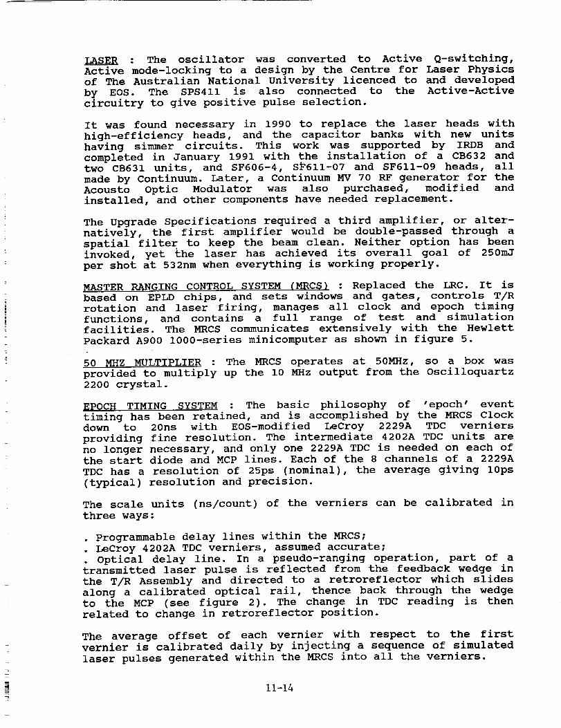
MASTER RANGING CONTROL SYSTEM (MRCS) : Replaced the LRC. It is
based on EPLD chips, and sets windows and gates, controls T/R
rotation and laser firing, manages all clock and epoch timing
functions, and contains a full range of test and simulation
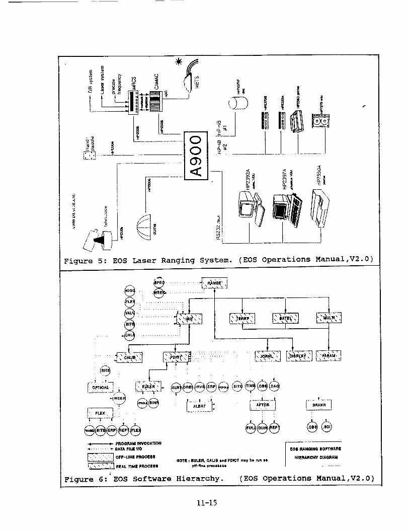
facilities. The MRCS communicates extensively with the Hewlett
Packard A900 1000-series minicomputer as shown in figure 5.
50 MHZ MULTIPLIER : The MRCS operates at 50MHz, so a box was
provided to multiply up the i0 MHz output from the Oscilloquartz
2200 crystal.
EPOC_ TIMING SYSTEM : The basic philosophy of "epoch' event
timing has been retained, and is accomplished by the MRCS Clockdown to 20ns with EOS-modified LeCroy 2229A TDC verniers
providing fine resolution. The intermediate 4202A TDC units are
no longer necessary, and only one 2229A TDC is needed on each of
the start diode and MCP lines. Each of the 8 channels of a 2229A
TDC has a resolution of 25ps (nominal), the average giving 10ps
(typical) resolution and precision.
The scale units (ns/count) of the verniers can be calibrated in
three ways:
• Programmable delay lines within the MRCS;
. LeCroy 4202A TDC verniers, assumed accurate;
Optical delay line. In a pseudo-ranging operation, part of a
transmitted laser pulse is reflected from the feedback wedge in
the T/R Assembly and directed to a retroreflector which slides
along a calibrated optical rail, thence back through the wedge
to the MCP (see figure 2). The change in TDC reading is then
related to change in retroreflector position•
The average offset of each vernier with respect to the first
vernier is calibrated daily by injecting a sequence of simulated
laser pulses generated within the MRCS into all the verniers.
11-14
-c
_; 0
° i/ /" 1
\_.,__.Io
!|
I ........
<:
Figure 5: EOS Laser Ranging System. (EOS Operations Manual,V2.0)
_k___J
.,,. , ............
.,.i................. :
_,:__ ,.-:--,_ " ___:,._:, r......_....., .... , ....
_ PROGRAM INVOCATION
< ......... 0ATA FIlE IIO
_ OFF-LIHI! PROOESII
_ IIEAL TIME pROOEe_
Figure 6: EOS Software Hierarchy.
ooe
L_
EOII RAN(lING IIOFTWARI!
HIERARCHY DIAQRAMHOTI : EtJLER, OAUB lnd PDICT rely be ru_1 le
(EOS Operations Manual, V2.0 )
11-15
RECEIVE ENERGY MONITOR : The previous system based on a LeCroy
2249A ADC has been retained, with hardware gating as above. The
EOS software contains an option for automatic gating.
DISCRIMINATOR : As before, Tennelec 454 CFD units are used. EOS
has experimented extensively with high-speed comparator chips,
delay lines and "cascade' configurations, but to date Orroral
prefers to use unmodified single channels. The upgrade has also
provided several potentially useful features for establishing
the Z-walk on each channel, such as the PLZT "wobbulator' and
software, which are still being evaluated.
OPERATING SOFTWARE : The upgrade software provided, which is
summarised in figure 6, includes mount modelling observations
and analysis, pass predictions from receipt of IRV/ORBEL files,
revamped EULER and IRVINT, ranging operations, post-processing
to generation of normal point, full-rate data and time bias
files, timing system calibration, file repair, diagnostic and
reporting software. Source code was not included. The originalsoftware release was designed to apply 'generically' to all EOS
systems; it has required considerable tailoring to Orroral's
specific configurations, peculiarities, environment and
requirements and has necessitated considerable re-education froman entrenched laser ranging 'culture'. Orroral prefers to use
its own post-processing software, modified from the Natmapsoftware to handle the new file structures.
Each interface driver is accompanied by a program demonstrating
all its calls and providing extensive diagnostic and simulation
capabilities. They cover CAMAC, MRCS, MPACS, PADDLE and DOME.
Ranging operations are built around three separate programs that
handle ground targets, satellites out to about 70ms two-way
range, and 'multiple shots in flight' targets such as ETALON and
the moon, respectively.
SYSTEM CALIBRATION : To date, the same methods for real-time
internal calibration and ground target ranging have been used as
were used during 1987-91. The 'Table Target' on the Coude Table
has been tested inconclusively; its signal strengths are
expected to be controllable much better than those from the
spider retros.
4. Laser Performance
An assessment was performed in April-May 1991 by Dr Barry
Luther-Davies of the Laser Physics Centre, Australian National
University. The results and many quotations given below are
taken from his report (Luther-Davies,1991). The upgrade to an
active/active oscillator and high-efficiency simmered heads has
clearly provided very satisfactory performance.
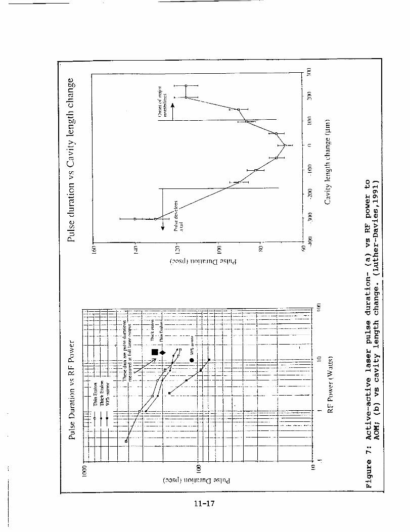
pULSE DURATION : Output from the Second Harmonic Generator was
measured using a Hadland Photonics IMACON 500 $20 streak camera
11-16
c-
o..)
P_
>
>
©
..,.A
(D
E_
t...
i I ,C _ C ¸
e-
g
v
C"
i..........................................
t
..-.__
II
...... I
---!1
(o_,_(I)uoT1_:.m_ _._In(l
.........'........2":--_-_---_-
t_lj
E
L,)
5,_0
L9
r_[.r,/
0 _
a_
.,-t
A_
t v
0
11),=
>-,.t gl
0
11),_>
O0
,u
t_
r_
11-17
whose negatives were digitized with a CCD camera. Three
different oscillator output reflectors were tested: a "thin"
(3mm) Quantel etalon, a "thick" (6mm) Quantel etalon, and a 50%
reflecting dielectric mirror. Pulse durations were measured as
functions of RF drive power level to the AOM (figure 7(a)) and
of cavity length (50% mirror only - figure 7(b)).
Minimum pulse durations at maximum appropriate RF drive power
and full laser power were:
with 50% mirror :
with thin etalon :
with thick etalon :
II0 +/- 5 ps
200 +/- i0 ps
240 +/- 12 ps.
The 50% mirror was subsequently adopted for normal use, and it
was concluded that the oscillator is relatively insensitive to
thermal expansion, +/- 5°C on a steel base being tolerable.
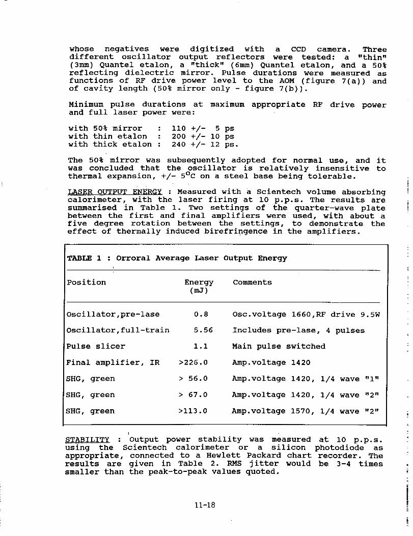
_S_R OUTPUT ENERGY : Measured with a Scientech volume absorbing
calorimeter, with the laser firing at i0 p.p.s. The results are
summarised in Table I. Two settings of the quarter-wave plate
between the first and final amplifiers were used, with about a
five degree rotation between the settings, to demonstrate the
effect of thermally induced birefringence in the amplifiers.
TABLE 1 : Orroral Average Laser Output Energy
I
Position Energy Comments
(mJ)
Oscillator,pre-lase
Oscillator,full-train
Pulse slicer
Final amplifier, IR
SHG, green
SHG, green
SHG, green
0.8
5.56
I.I
>226.0
> 56.0
> 67.0
>113.0
Osc.voltage 1660,RF drive 9.5W
Includes pre-lase, 4 pulses
Main pulse switched
Amp.voltage 1420
Amp.voltage 1420, 1/4 wave "I"
Amp.voltage 1420, 1/4 wave "2"
Amp.voltage 1570, 1/4 wave "2"
| •
STABILITY : Output power stability was measured at i0 p.p.s.
using the Scientech calorimeter or a silicon photodiode as
appropriate, connected to a Hewlett Packard chart recorder. The
results are given in Table 2. RMS jitter would be 3-4 times
smaller than the peak-to-peak values quoted.
11-18
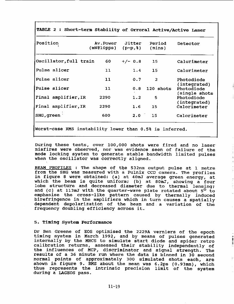
TABLE 2 : Short-term Stability of Orroral Active/Active Laser
Position Av.Power Jitter Period Detector
' (mW@10pps) (p-p,%) (mins)
Oscillator,full train 60 +/- 0.8 15
Pulse slicer Ii 1.4 15
Pulse slicer ii 0.7
Pulse slicer Ii 0.8
Final amplifier,IR 2290 1.2
Final amplifier,IR 2290 1.6
SHG,green 600 2.0 15
Calorimeter
Calorimeter
2 Photodiode
(integrated)120 shots Photodiode
(single shots5 Photodiode
(integrated)
15 Calorimeter
Calorimeter
Worst-case RMS instability lower than 0.5% is inferred.
During these tests, over i00,000 shots were fired and no laser
misfires were observed, nor was evidence seen of failure of the
mode locking system to generate stable bandwidth limited pulses
when the oscillator was correctly aligned.
BEAM PROFILES : The shape of the 532nm output pulse at 1 metre
from the SHG was measured with a Pulnix CCD camera. The profiles
in figure 8 were obtained: (a) at 40mJ average green energy, at
which the beam is quite uniform; (b) at 80mJ, showing a four
lobe structure and decreased diameter due to thermal lensing;
and (c) at ll3mJ with the quarter-wave plate rotated about 5 ° to
emphasise the cross-like pattern caused by thermally induced
birefringence in the amplifiers which in turn causes a spatially
dependent depolarization of the beam and a variation of the
frequency doubling efficiency across it.
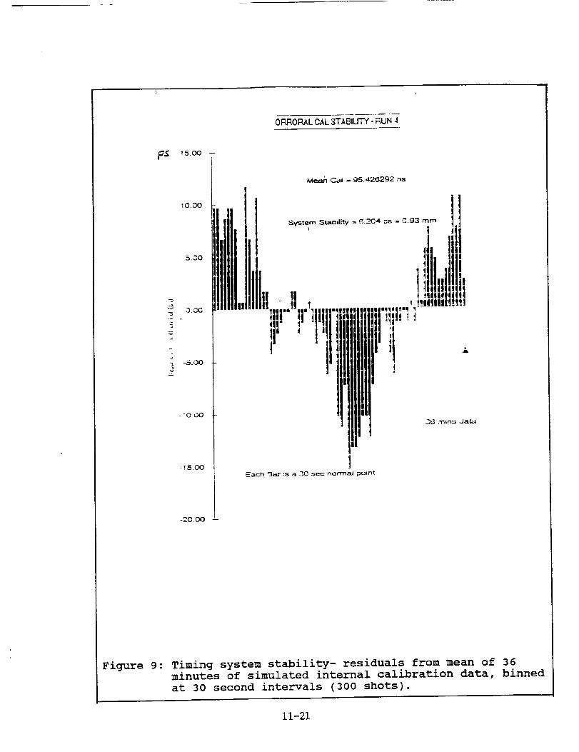
5. Timing System Performance
Dr Ben Greene of EOS optimised the 2229A verniers of the epoch
timing system in March 1992, and by means of pulses generated
internally by the MRCS to simulate start diode and spider retro
calibration returns, assessed their stability independently of
the influences of MCP, discriminator and signal strength. Theresults of a 36 minute run where the data is binned in 30 second
normal points of approximately 300 simulated shots each, are
shown in figure 9. RMS about the mean was 6.2ps (0.93mm), which
thus represents the intrinsic precision limit of the systemduring a LAGEOS pass.
11-19
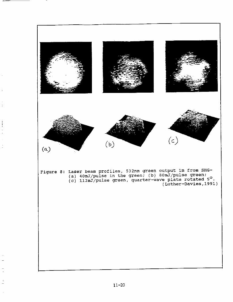
Figure 8: Laser beam profiles, 532nm green output Im from SHG-(a) 40mJ/pulse in the green; (b) 80mJ/pulse green;(c) ll3mJ/pulse green, quarter-wave plate rotated 5° .
(Luther-Davies,1991)
11-20
OF:LROFLALOAL STABILITY - _UN 4
-15oo
-20.00 --
Mean C_I = 95.426292 ._s
I£acm Bar is a 30 sec normal point
Figure 9: Timing system stability- residuals from mean of 36
minutes of simulated internal calibration data, binned
at 30 second intervals (300 shots).
11-21
A systematic variation visible in figure 9 may be due to
temperature variations in the CAMAC modules. The residuals from
a 20 minute run were more random, with RMS 2.4ps (0.36mm).
An estimate of long-term stability is obtained from the daily
calibration of the relative delay between verniers. In a 50 day
period analysed during which the vernier scale units (ps/count)were held fixed at their values determined at the start of the
period, the RMS variation of the delay difference between the
two units actually used in ranging was 6.6ps (l.0mm).
It is thus evident that the precision and stability of the
system, given perfect discriminator outputs, are imm or better.
Because range calculations necessarily involve only vernier
differences, this value also represents the accuracy limit of
the system.
Data on the optical rail method of timing system calibration insitu at Orroral has not been obtained,
6. Pass Productivity
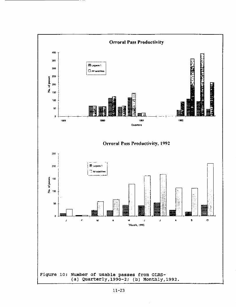
In figure 10(a), the growth in the number of passes acquired perquarter as a result of the upgrade is demonstrated. Prior to
March 1991, only LAGEOS I and ETALON I & II (from June 1990)were observable. With the upgrade, STARLETTE, AJISAI and ERS-I
were immediately acquirable, with TOPEX/POSIDON and LAGEOS II
being added in the second half of 1992. It is notable that the
upgraded Orroral system was the first station to get returns
from LAGEOS II, on 24 October. Monthly statistics for January toOctober 1992 are given in figure 10(b).
An unexpected consequence of the upgrade is that, in view of the
enormous increase in number of passes available and the far
greater reliability of the upgraded segments of the OLRS, more
operational staff are needed in spite of greater system
efficiency, and more technical staff are needed to maintain the
other segments and bring them to an equal state of reliabilityand efficiency.
7. System Precision
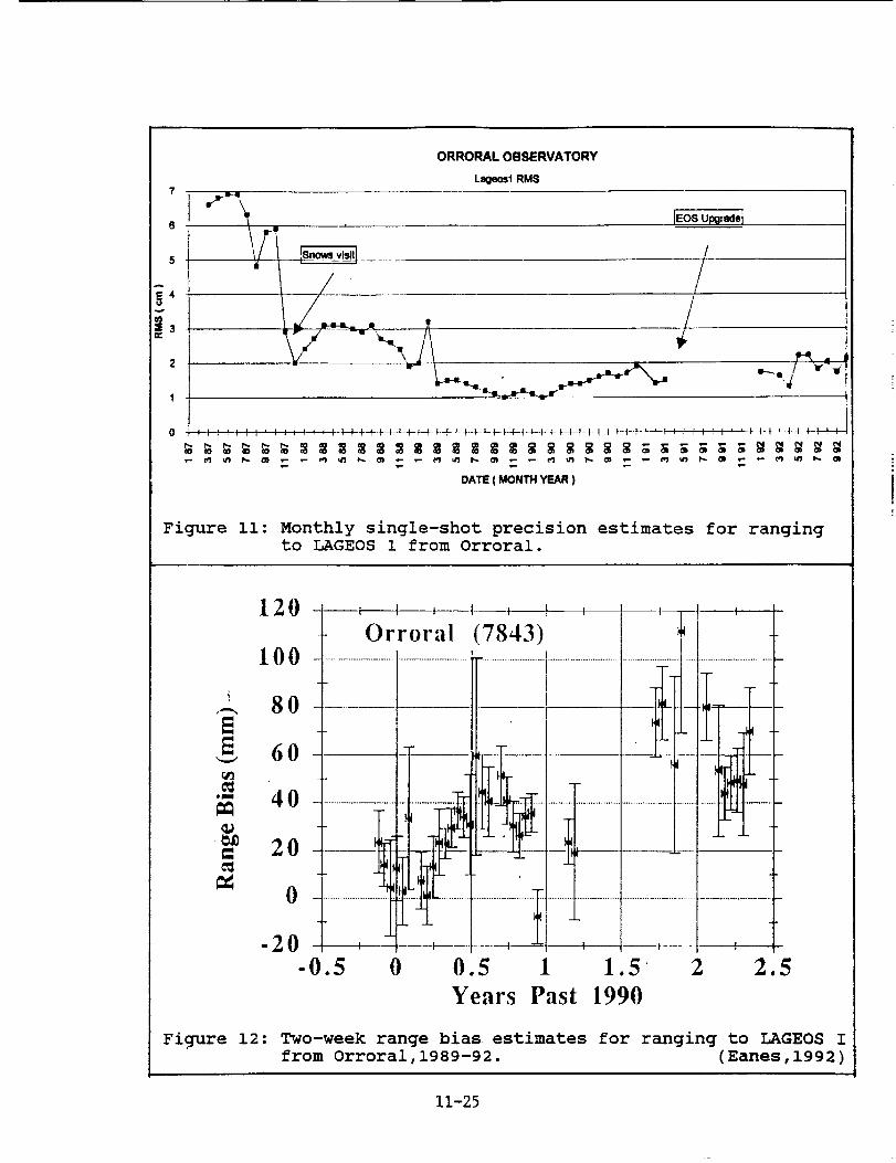
The evolution of single-shot precision estimates for LAGEOS I
ranging from Orroral is shown in figure Ii. The data prior to
the upgrade come from analyses of full-rate data by Peter Dunn
of STX, and from in-house analysis thereafter. The failure to
achieve the upgrade's sub-centimetre potential is ascribed to
deterioration in laser aii_ment leading to longer pulses, to
the difficulties encountered in optimising the MCP-Discriminator
combination, and to a clear dependence of delay upon signal
strength. Every effort is made to equalise signal strength
distributions from satellite returns, spider retro cals and
11-22
Orroral Pass Productivity
4OO
350
3O0
250
:_ ;so
+++ m,+i +°!+++__+NW0 ......... I- _- ,
19,99 I_30 1992
250
Orroral Pass Productivity, 1992
200
I
SO
[ .........
F-_ All saletlit_
F M A J s o
Figure i0: Number of usable passes from OLRS-
(a) Quarterly,1990-2; (b) Monthly,1992.
11-23
ground target returns by judicious manipulation of the PLZT and
telescope pointing, but it is difficult to do this in practice.
Ground target ranging offers more control over signal strengths.
RMS values of 30ps (4.5mm) have been obtained in 5 minute
sessions both for raw ground target returns uncorrected for
refraction, and for internal calibrations. About 7mm is normal
when everything is working properly, as illustrated for a good
month in figure 13.
8. System Accuracy
Agreement with external standards is assessed two ways. It has
not been possible to organise a co-location experiment.
COMPARTSON WITH GROUND SURVEYS : The distance from the ground
target retroreflector to all relevant instrumental points was
measured by precise geodetic survey in late 1987 and repeated by
independent methods and operators in late 1989. The formal one-
sigma uncertainty of each survey was 3mm, and agreement was 8mm.
The value adopted for the distance between the ground target and
spider retro #i from the more recent survey is i141624mm.
The same distance is estimated from laser ranging by subtracting
the calibration result from the raw range measurement, and
applying a refraction correction based on EDM theory and
meteorological readings (Rueger,1980). No other corrections for
delays inside the telescope are needed. Results for the first
ten months of 1992 are displayed in figure 13. The extent to
which improvements in signal strength control and laser pulseduration control will decrease the scatter and mean error,
remains to be seen.
LAGEOS _ RANGE BIAS : Figure 12 shows the range biasses before
and after the upgrade, relative to LAGEOS I orbits computed by
the Center for Space Research, University of Texas (Eanes,1992).
There is evidence of a jump of between 20 and 60mm, but it is
inconclusive as there could be contamination from orbit errors,
station position errors, inclusion of data from 1991 when the
upgrade was still being de-bugged, and truncation atMay 1992.
There has been no change in the constants and procedures used to
reduce raw ranges to the adopted instrumental reference point
(Coude mirror 7 - see figure i), nor in the refraction algorithm
applied to quick-look data. The Orroral reduction procedure is
given in Appendix i.
9. Telescope Pointing
MOUNT MODELLING : The analytical model developed previously for
the Contraves mount and MPACS encoder system was specially coded
into the generic EOS software. There are i0 parameters for each
axis. It is solved from star observations by a non-linear
process with observed encoder readings as the basic arguments.
(The previous implementation by Natmap was solved as a linear
11-24
7
6
5
g,2
1
0
ORRORAL OBSERVATORY
L_e_IRMS
//
/
Figure ii: Monthly single-shot precision estimates for rangingto LAGEOS 1 from Orroral.
0_
12 0 ---__--=_-_--_ , ' 1 '-- Orroral (7843) i --
1 O0 .........................................................................................................t.....................................................................................................t - -
60 _--- f!r
_. - i- -°-_i- --I
_t41i ._1 .... ' -"O .................................. :: ...-.. | 1 ""t ........................................................................................................
i --
"20 --------4 -- +------ ------4----_t--------+ f ÷
-0.5 0 0.5 1 1.5 2 2.5
Years Past 1990
Figure 12: Two-week range bias estimates for ranging to LAGEOS Ifrom Orroral,1989-92. (Eanes,1992)
11-25
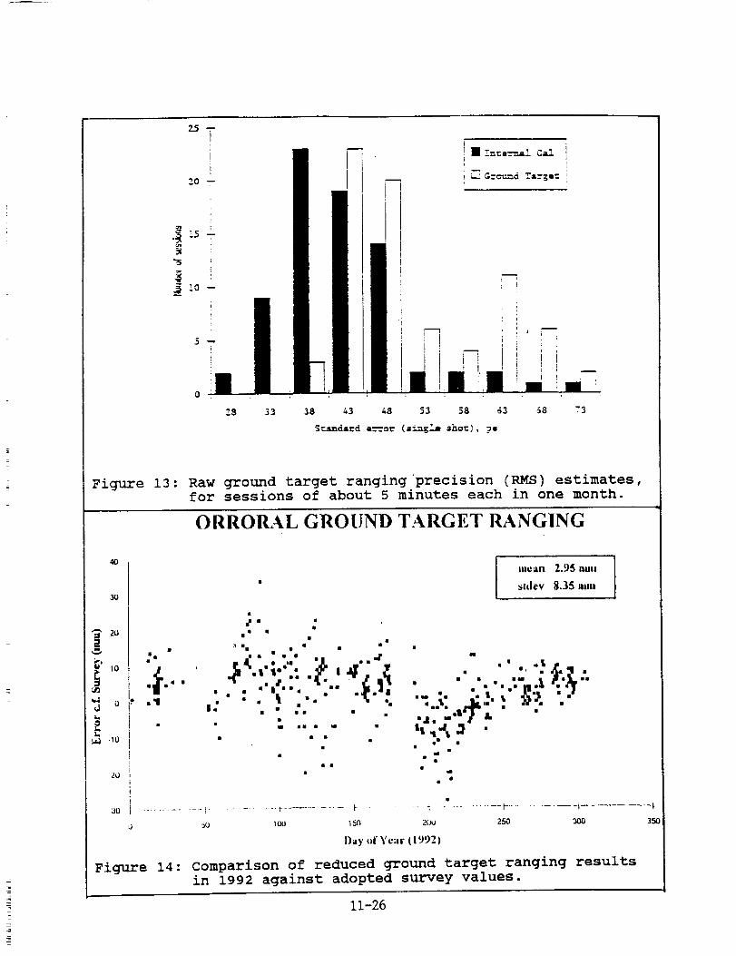
Figure 13: Raw ground target ranging precision (RMS) estimates,
for sessions of about 5 minutes each in one month.
ORRORAL GROUND TARGET RANGING
4O
30
20
0'3
d
.io
2o
._ ". .:ill • il •
=_I. • .,. 'Jr " " .' • .$_.q ••l''' .: ._'= I • ' •
• "'.'" _.'_r'"
" i_ """ _"" "" '""'_ :"
• : : 'l :'." " """" "., _", . . .. ...L .,h'- . _"-=d .,.11,'#11 &
_ _• 111 I
_o _oo _5c_ 2c_J 2so _oo
Day -1" Y¢;ir ( ! 992)
Figure 14: Comparison of reduced ground target ranging results
in 1992 against adopted survey values.
11-26
350
model with ideal encoder readings as arguments.) The model is
described in Appendix 2.
The star catalogue used is the FK4; previously, we used the
homogeneous Perth 70 catalogue, which has a denser distribution•
Star observations are accomplished at the eyepiece at the
Cassegrain focus• Star images are set, not on the eyepiece
graticule centre but on the image of the coincident 'green
spots' formed by returns from the two retroreflectors on the
secondary mirror's spider vanes while the laser is firing• Thus
the star is set in the direction in which the laser is actually
transmitted, which automatically accounts for mlsalignments in
the Coude path.
A feature of the upgraded system is that, between each repeat
observation (normally 3) on each star, the telescope is driven
off in a 'random direction to minimise personal bias and any
backlash• In other respects, observing speed and the star
selection algorithm are inferior to those prior to the upgrade•
HANDPADDLES : For operator convenience in both star observations
and ranging, the new handpaddles have thumbwheels to select the
resolution of each 'click' of the paddle buttons. This feature
has proven very useful•
POINTING ACCURACY AND PRECISION : The post-fit standard error of
a full mount model solution from more than 20 stars is typically
3 seconds of arc. The upgrade's solution software does not
provide the facility to asses numerically how closely the
current model points to stars, so it has to be done at the
eyepiece. Our estimate is 5-10 seconds of arc, which is also the
typical pointing error to the more distant satellites.
i0. Future Upgrades and Extensions
The EOS system is designed to be open-ended for future
development• Post-upgrade projects already completed or in-handinclude:
• Semi-automatic ranging operations;
• Variable speed dome automation;
• Implementation of 'Table Cals';
• Variable optical attenuation for satellite returns;
• Optical design and fabrication for SPAD installation;
• NP 9000-series Unix workstation for all displays, processing
and graphical user interface, leaving the HP A-900 only forinstrument control•
while projects made possible in the more distant future include:
• Fully automatic ranging;
• Converting laser to travelling-wave 'ring' design;
• Operating at 40 shots per second;
• Multi-colour ranging•
11-27
An important development not directly related to the upgrade butnecessary for lunar ranging and desirable for optimum focussingon to a SPAD, is a new telescope secondary mirror which shouldbe installed by July,1993. Its distance from the primary mirrorwas reduced by 4cm at the 1981 upgrade, which introducedenormous aberrations in the Ritchey-Chretien system because itwas inadvertently assumed to be a true Cassegrain at the time
(see,e.g. Schroeder,1987). A new optical prescription has beencalculated which retains the existing primary mirror, matching
assembly and tailpiece optics, reduces the inter-vertex distance
by a further 4.5cm, eliminates coma and spherical aberration
from the telescope, and reduces them considerably in the
matching lens assembly (James,1992).
The heavily aberrated field-of-view at the pinholes in the
receiver assembly is essentially zero (James,1992). The layout
of assemblies on the Coude Table is being studied, to bring the
receiver optically closer to the Beam Expander, if possible, in
order to increase the field-of-view somewhat.
II. Acknowledgements
The financial support of IRDB, EOS and AUSLIG is gratefully
acknowledged. The Orroral Observatory Advisory Committee chaired
by Kurt Lambeck, and AUSLIG management particularly Grahame
Lindsay, Wal Lamond, Peter O'Donnell and John Manning, were
instrumental in initiating the upgrade. The staff of EOS led by
Ben Greene with Grant Moule as Project Manager, and all the
staff of Orroral Observatory, worked long and hard to instal and
debug the new systems and mate them to Orroral's needs and
environment.
Special thanks to John Degnan for his patience waiting for this
manuscript, and to Mark Elphick and Steve Cootes for their
beautiful drawings and graphs.
12. References
Eanes,R.(1992): Private communication,May.
James,W.E.(1992): "Report on Visit to Orroral Valley Laser
Ranging Observatory",Contract Report,James Optics P/L,
July.Luther-Davies,B.(1991): "AUSLIC Laser Operating Manual and Test
Data",Contract Report,Australian National University,June
Rueger,J.M.(1980): ,,Introduction to Electronic Distance Measure-
ment",Monograph No.7 (2nd Ed),The School of Surveying,
University of New South Wales,March.
Schroeder,D.J.(1987): "Astronomical Optics",Academic Press Inc.
11-28
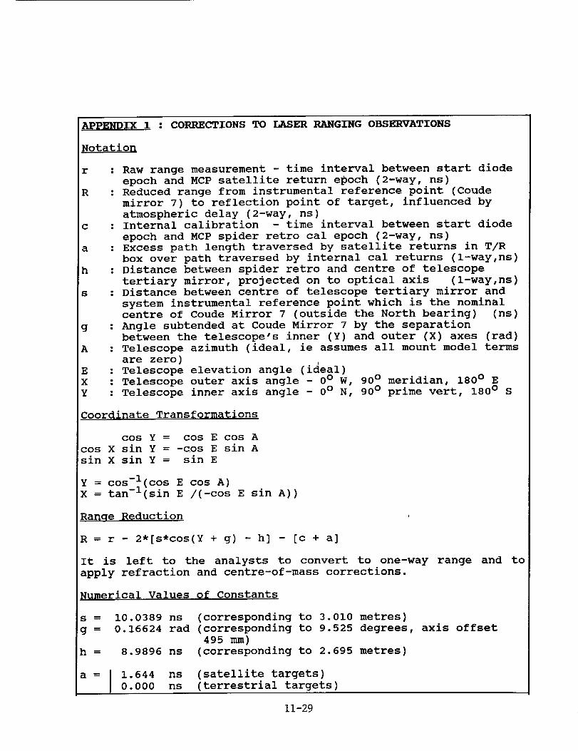
APPENDIX 1 : CORRECTIONS TO LASER RANGING OBSERVATIONS
Notation
r
R
c
a
h
s
g
A
E
X
Y
: Raw range measurement - time interval between start diode
epoch and MCP satellite return epoch (2-way, ns)
: Reduced range from instrumental reference point (Coude
mirror 7) to reflection point of target, influenced by
atmospheric delay (2-way, ns): Internal calibration - time interval between start diode
epoch and MCP spider retro cal epoch (2-way, ns)
: Excess path length traversed by satellite returns in T/R
box over path traversed by internal cal returns (l-way,ns)
: Distance between spider retro and centre of telescope
tertiary mirror, projected on to optical axis (l-way,ns)
: Distance between centre of telescope tertiary mirror and
system instrumental reference point which is the nominal
centre of Coude Mirror 7 (outside the North bearing) (ns)
: Angle subtended at Coude Mirror 7 by the separation
between the telescope's inner (Y) and outer (X) axes (rad)
: Telescope azimuth (ideal, ie assumes all mount model terms
are zero): Telescope elevation angle (ideal)
: Telescope outer axis angle - 0 ° W, 90 ° meridian, 180 ° E
: Telescope inner axis angle - 0 ° N, 90 ° prime vert, 180 ° S
Coordinate Transformations
cos Y = cos E cos A
cos X sin Y = -cos E sin A
sin X sin Y = sin E
Y = cos-l(cos E cos A)
X tan -l(sin E /(-cos E sin A))
Ra_qe Reduction
R = r - 2*[s*cos(Y + g) - h] - [c + a]
It is left to the analysts to convert to one-way range and to
apply refraction and centre-of-mass corrections.
Numerical Values of Constants
S
g =
h
10.0389 ns (corresponding to 3.010 metres)
0.16624 rad (corresponding to 9.525 degrees, axis offset
4958.9896 ns (corresponding to 2.695 metres)
a = I 1.644
I 0.000
ns (satellite targets)
ns (terrestrial targets)
11-29
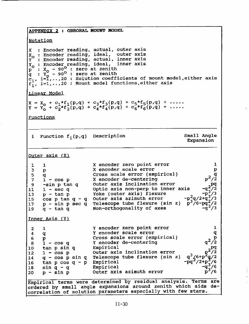
A_L__2 : ORRORALMOUNT MODELNotation
X : Encoder reading, actual, outer axis
X O : mncoder reading, ideal, outer axis
Y : Encoder reading, actual, inner axis
Yo : Encoder readzng, ideal, inner axis
p : X o - 90 ° : zero at zenith
q : y - 90 ° : zero at zenith
ci, i=_,..,20 : Solution coefficients of mount model,either
fi, i=I''''20 : Mount model functions,either axis
Linear Model
X = X o + cl*fl(P,q)+ c3*f3(P,q) + c5,*f5(p,q) + .....Y Yo + c2q)*f2(p, + c4*f4(p,q) + c 6 f6(P,q) + .....
Functions
axis
i Function fi(p,q) Description Small Angle
Expansion
Quter axis (x!
1 1
3 p
5 q
7 1 - cos p
9 -sin p tan q
ii 1 - sac q
13 p - tan p
15 cos p tan q - q
17 p - sin p sac q
19 q - tan q
Inner Axis (Y)
X encoder zero point error 1
X encoder scale error p
Cross scale error (empirical)X encoder de-centering p2/
Outer axis inclination error pq
Optic axis non-perp to inner axis -q2/2
Yoke (outer axis) flexure _ -p_/3
Outer axis azimuth error -p_q/2+q_/3
Telescope tube flexure (sin z) p_/6-pq_/2Non-orthogonality of axes -q /3
2 1 Y encoder zero point error 1
4 q Y encoder scale error q
6 p Cross scale error (empirical)8 1 - cos q Y encoder de-centering q2/
L0 tan p sin q Empirical pq12 1 - cos p Outer axis inclination error 3 _ 2/2
14 q - cos p sin q Telescope tube flexure (sin z) q _6+p _/216 tan p cos q - p Empirical -pq /2+p_/6
18 sin q - q Empirical -q_/6
20 p - sin p Outer axis azimuth error p_/6
Empirical terms were determined by residual analysis. Terms are
ordered by small angle expansions around zenith which aids de-
correlation of solution parameters especially with few stars.
11-30
and
SUB--CM
other
in
N94-15603
Ranging
improvements
Sra z
Georg KIRCHNER, Franz KOIDL
SLR Graz / Institute for Space Research
Austrian Academy of sciences
Observatory Lustb_hel, Lustb0helstr. 46
A-8042 GRAZ, AUSTRIA
!
Tel.: +43-316-472231; Fax: +43-316-462678
E-Mail: [email protected]
1.0 Introduction
A lot of tests and experiments have been made in Graz during
the last 2 years to increase performance and accuracy; using the
SPAD from the Prag group as receiver, we have reached now about 5
mm RMS from the calibration target, and about 8 mm RMS from ERSI
and STARLETTE. In addition, routinely using the semitrain, the
number of returns has been increased significantly for most
satellites.
2.0 Experiments
In January 1991, together with the Prague group, we installed
their streak camera as a receiver in the Graz laser telescope,
and first echoes from AJISAI and STARLETTE could be recorded.
In December 1991, again together with the Prague colleagues,
2-color ranging experiments were performed, using Raman upshifted
red (683 nm) and 532 nm wavelengths; returns of both colors from
AJISAI and LAGEOS could be recorded. A detailed description of
both experiments is given elsewhere in these proceedings.
11-31
3.0 Accuracy Improvements
As stated already during the Matera workshop, the contribution
of the SPAD itself to the overall jitter can be decreased by
using higher voltages above break (Vab). Modifications of the
original SPAD electronics now allow us to increase this Vab to!
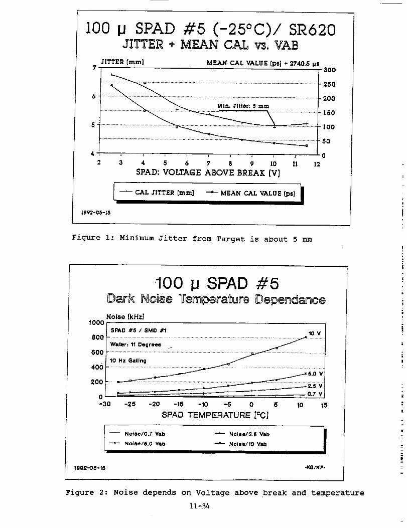
more than i0 V, resulting in a jitter of 5 mm RMS (fig. l) from
the calibration target. In this test, we used an SR620 counter,
which also contributes to the lower RMS (the start input of the
SR620 handles the output of the start Optoswitch significantly
better than our HP5370A).
The well known disadvantage of the high Vab is the increase in
noise; while a standard SPAD at 2.5 Vab at room temperature has
an acceptable noise of about 200 kHz or less, this increases at
I0 Vab to about 1 MHz (fig. 2). To reduce this, we cool the SPAD
now with Peltiers to -25°C, reaching again about 200 kHz noise.
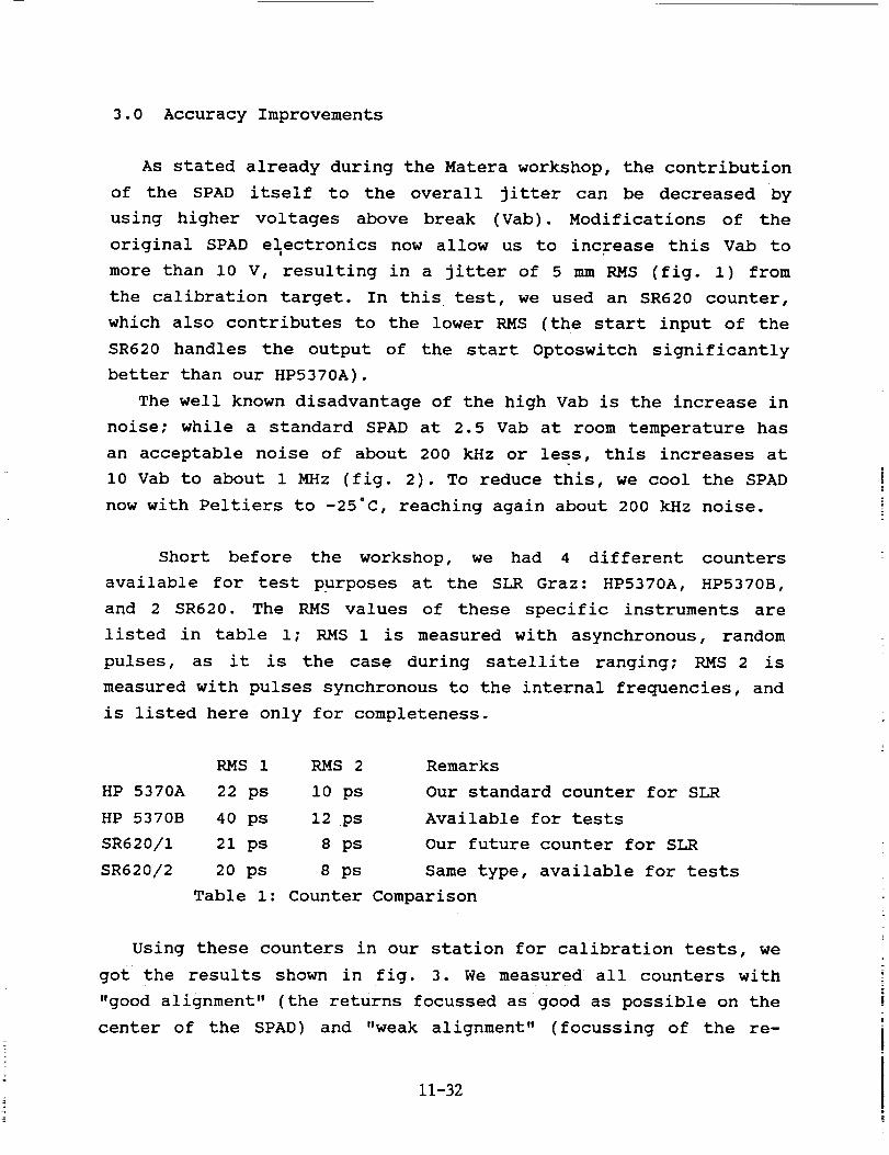
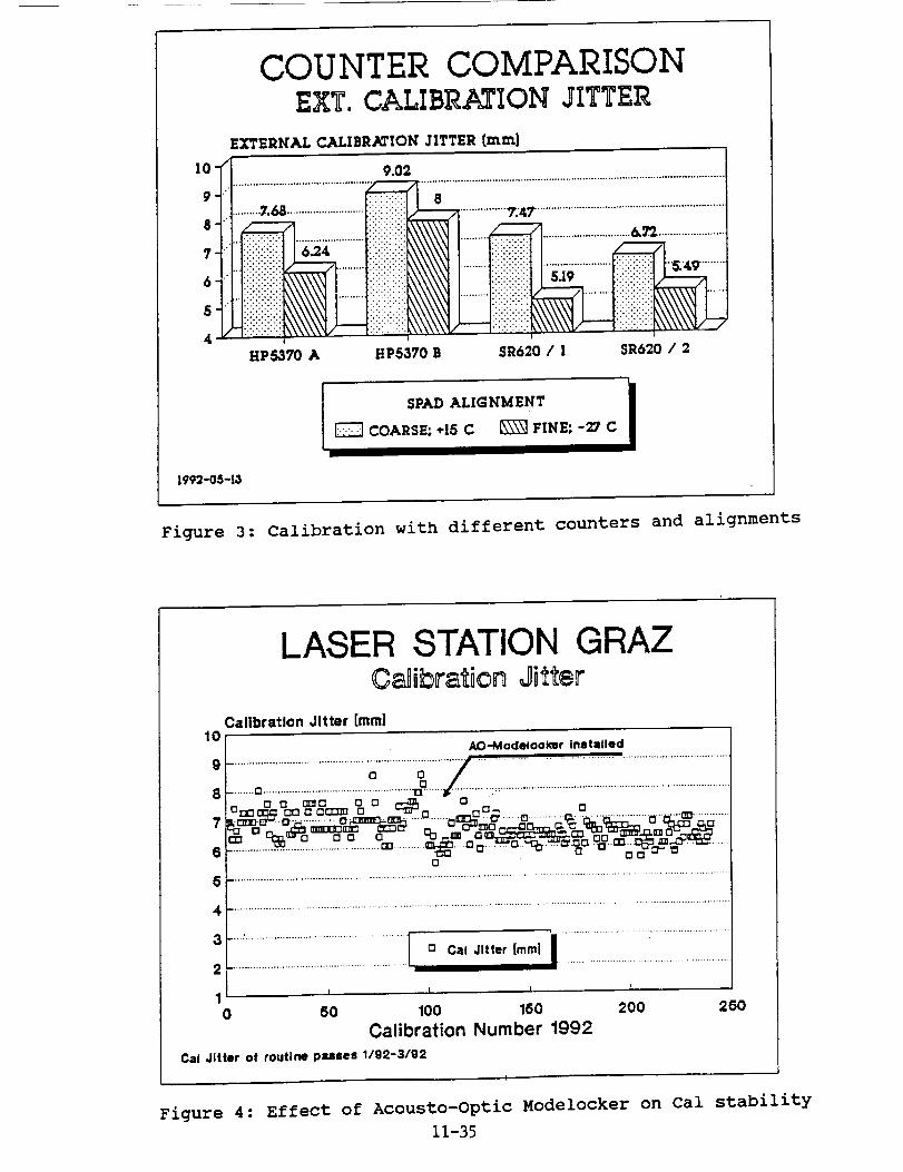
Short before the workshop, we had 4 different counters
available for test purposes at the SLR Graz: HP5370A, HP5370B,
and 2 SR620. The RMS values of these specific instruments are
listed in table i; RMS 1 is measured with asynchronous, random
pulses, as it is the case during satellite ranging; RMS 2 is
measured with pulses synchronous to the internal frequencies, and
is listed here only for completeness.
RMS 1 RMS 2
HP 5370A 22 ps i0 ps
HP 5370B 40 ps 12 ps
SR620/I 21 ps 8 ps
SR620/2 20 ps 8 ps
Remarks
Our standard counter for SLR
Available for tests
Our future counter for SLR
Same type, available for tests
Table I: Counter Comparison
Using these counters in our station for calibration tests, we
got the results shown in fig. 3. We measured all counters with
"good alignment" (the returns focussed as good as possible on the
center of the SPAD) and "weak alignment" (focussing of the re-
11-32
turns on the S_AD far from optimum). It can be seen that good
SPAD alignment (together with optimizing all start/stop input
pulse rise times, pulse forms, trigger thresholds etc.) is of the
same importance than selecting the proper counter.
4.0 Routine use of the Semitrain
Since summer 1991, we routinely use the second half of the
pulse train (semitrain), delivered from our Nd:YAG laser, for allSLR measurements. The software has been modified to allow for au-
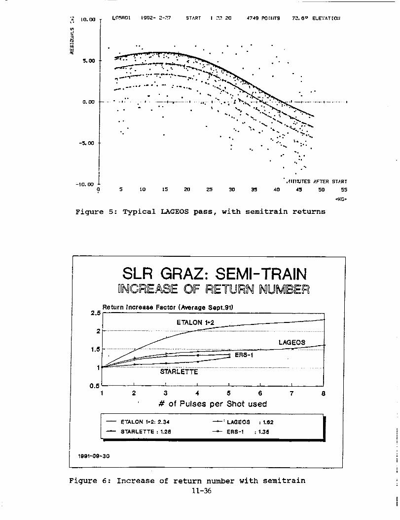
tomatic "folding" of the returns. Fig. 5 shows an example pass of
LAGEOS, with totally 7 tracks (or pulses from the semitrain)
identified later by the software.
By using all returns from the semitrain, the number of returns
for most satellites could be increased significantly (fig. 6);
for LAGEOS the increase in returns is more than 50%; for the
ETALON's, it is more than doubled.
5.0 Acousto-Optic Modelocker
In February 1992, we installed an Acousto-Optic Modelocker in
our old Nd:YAG laser oscillator, inceasing reliability and shot-
to-shot reproducibility of the laser pulses. Besides increasing
the number of valid shots from our previous average of about 70%
(it was an old, purely passiv modelocked oscillator!) to more
than 99%, the much better stability of the pulses had a notice-
able effect on the jitter (Fig. 4); the routine cal. values
showed better stability and even slightly lower RMS ..(the AO-
Modelocker was installed after calibration number 98, in fig. 4).
The AO-Modelocker requires temperature stabilization; this is
done by slighly heating it to 27 ° , using the hot side of Peltier
elements; the cold side of these elements is used at the same
time to cool the Dye Cell to about I0 ° , which should result in a
longer lifetime of the Dye. Results are promising (we used the
same dye from February to May), but still have to be verified
during the next years.
11-33
I00 _JSPAD #5 (-25°C)/ SR::0JITTER + MEAN CAL vs,VAB
JITTER [ram]?
MEAN" CAL VALUE [ps] ÷ 2740.5 Ms
.
5fl
4I 1 _ I ! I l ; J
2 3 4 5 6 7 8 9 10 11 12
SPAD: VOLTAGE ABOVE BREAK [V]
300
250
200
150
100
50
0
-- CAL JITTER [mm] "'6-- MEAN CAL VALUE [ps]
1992-05-15
Figure i: Minimum Jitter from Target is about 5 mm
1000
100 i.JSPAD #5Dark Noise Temperature Dependance
Noise [kHz]
800
600
406
200
0-30
$PAD #5 / SMD #1 10 V
10 Hz Gallng
-25 -20 -16 -10 -5 0 5 10 15
8PAD TEMPERATURE [¢C]
-- Noise/0.7 Wtb
--"- Noise/5.0 Vab
k-'_ Noise/2.5 V_b II
IN0ise/10 Vab
1992-05-15 ,KG/KF,
Figure 2: Noise depends on Voltage above break and temperature
11-34
C 9UNTER COMPARISONEXT, CALIBRATION JITTER
EXTERNAL CALIBRATION JITTER [mm]
]0-_ 9.02 ...............................
9 ................................................ :'<._i_::i ...... 8" ....................................................................
atiill .... i!iiiiii!iiii _ ............................_.= ......................., iiiiiiiiii__<iiiiiii_!_i_i_!_i_i_iiiiiii .....6 -ii!i!iiiii!ii .........iiiiiiiilili! ..........:i:_:i:i:i:_:i, iiil !ilili! ii
HP5370 A HP5370 B $R620 / 1 SR620 / 2
I SPAD ALIGNMENT iCOARSE; +15 C [_ FINE; -_ C
1992-05-1.1
Figure 3: Calibration with different counters and alignments
I0
LASEP STATION GRAZC_ibration Jitter
Calibration Jitter [mini
9t ...............................................;;.............._............................I.. or, _,n o [] _-_ o, "_o:_ o,', [] ac:__ o9._ --"_ c ___•.c o ............. 0. .............................._ .............
o
4 .....................................................................................................................................
3 n Cal Jitter [mml
_ ............................................
1 ' I '0 50 100 160
Calibration Number 1992
200 250
Cal Jitter of routine passes 1/92-3/92
Figure 4: Effect of Acousto-Optic Modelocker on Cal stability
11-35
_. I0.00I,
-J
IN|11
-5. 011
Lt_ROt tgg2- _-._7 START ! ,".2 20 47,1g POitlTS 72.6 ° ELEVATTO:!
I
-LO. O0 ._.I|}IUTE$ AFTER START
0 5 L0 15 20 25 30 35 40 45 50 55
_KG>
Figure 5: Typical LAGEOS pass, with semitrain returns
2.5
SLR GRAZ: SEMI-TRAIN_[_CF_EASEOF _TU_N I_UMI_IEF_
Return Increase Factor (Average Sept.91)
2
1.5
1
0.51
ETALON 1-'2
......................................................................................
....................._ .......................................,........................,..................
___._______ ERS-1
STARLETTE
I I I l _ I
2 3 4 5 6 7 8
# of Pulses per Shot used
-- ETALON 1-2:2.34 --_-I LAGEOS : 1.62"-"- STARLETTE : 1.28 -4- ER8-1 : 1.35
lggl-Og-30
Figure 6: Increase of return number with semitrain
11-36
N94-15604
UPGRADING OF THE BOROWIEC LASER STATION
S.Schillak, E.Butkiewicz, J.Wiktorowski
Space Research Center of Polish Academy of Sciences
Astronomical Latitude Observatory
Borowiec 91
62-035 Kornik, Poland
Telephone: (48) 61-170-187
Fax: (48) 61-170-219
Telex: 412623 aos pl
Abstract
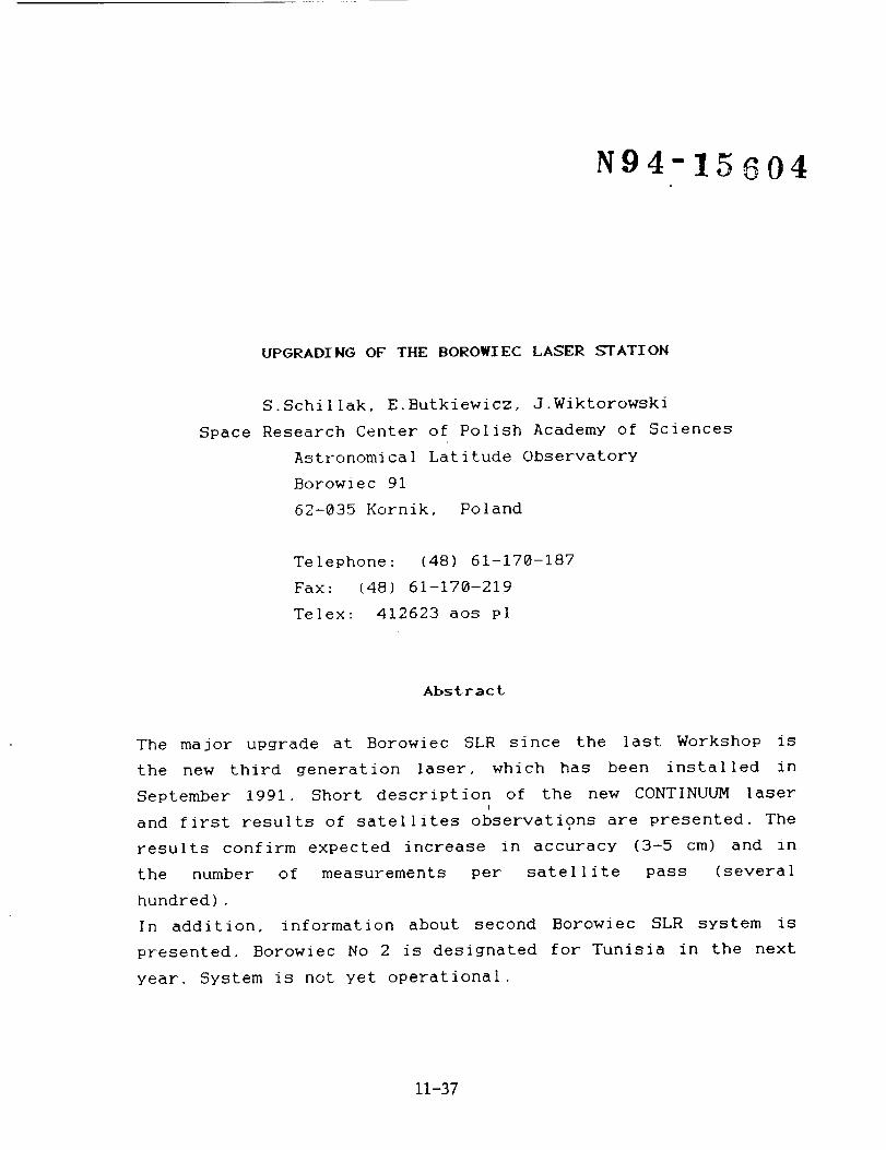
The major upgrade at Borowiec SLR since the last Workshop is
the new third generation laser, which has been installed in
September 1991. Short description of the new CONTINUUM laserl
and first results of satellites observations are presented. The
results confirm expected increase in accuracy (3-5 cm) and in
the number of measurements per satellite pass (several
hundred).
In addition, information about second Borowiec SLR system is
presented. Borowiec No 2 is designated for Tunisia in the next
year. System is not yet operational.
11-37
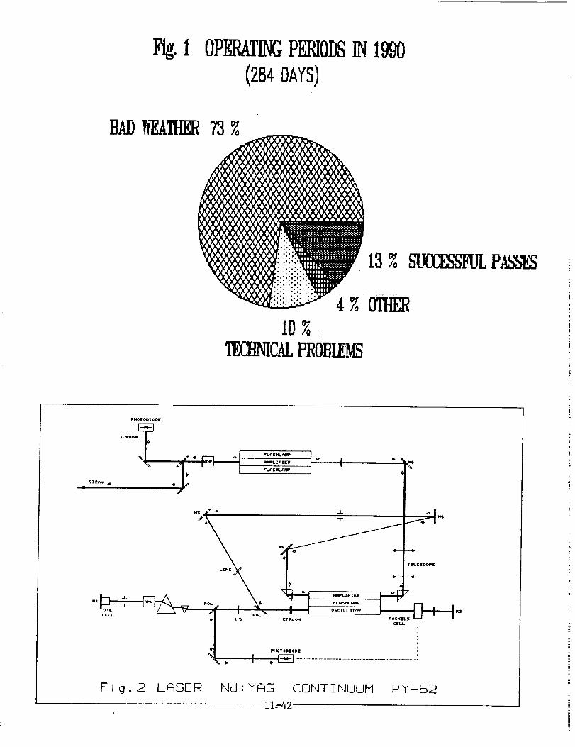
I. Introduction.
The Borowiec SLR System is operating since 1988 (Schillak,
1991). During this time the system has provided observations tosatellites LAGEOS, Ajisai, Starlette, GEO-IK-I and ERS-I. The
system has only night-time tracking capability. The single shot
precision was estimated to be about Z28 cm. Our activity
were strongly limi'ted by bad weather conditions and technical
problems (Fig.l).
Since the last workshop several upgrading in the system has
been done;
- 1998, February, transmitter telescope has been added and
divergence of laser beam changed 8X,
- 1998, October, generation of normal points onsite,
- 1998, October, replacement of the photomultipIier FEU-87 by
the RCA 8852,
- 1991, June, a received energy detector has been introduced,
- 1991, September, new third generation laser has been
inst'alled,
- 1991, October, new real-time software has been introduced,
- 1992, January, microcomputer PC/AT has been used for pre- and
post-observation programs, real-time graphic program on
PC/AT has been added.
The main upgrading of the system was installation of the newi
laser.
2. Laser CONTINUUM.
The Nd:YAG laser type CONTINUUI_ PY-62-18 has been employed in
September, 1991. The scheme of the laser transmitter is shown
in Fig.2. The laser is a cavity dumped active/passive
mode-locked system. The cavity dump consist of the
electro-optic Pockels cell triggered by a photodiode. The
selected output single pulse is ejected via polarizer when the
predetermined intensity level is reached. The oscillator
delivering about 3-5 mJ at 1864 nm. The oscillator and
preamplifier are pumped by the same flash]amp. A telescope for
beam expansion is placed before main amplifier. The amplifier
has four flashlamps. A type II KD P crystal is used for
11-38
doubling.The laser can be operated in two different modes;
- with ETALON (180' ps, 110 mJ at 532 nm),
- without ETALON (35 ps, 65 mJ at 532 nm).
The pulse repetition rate can be varied from 1 to 10 Hz (10 Hz
is optimum). Pulse stability. - 7%, diameter of output laser
beam - 12 mm, divergence - 0.4 mrad, jitter of ext. trig. _10
us.
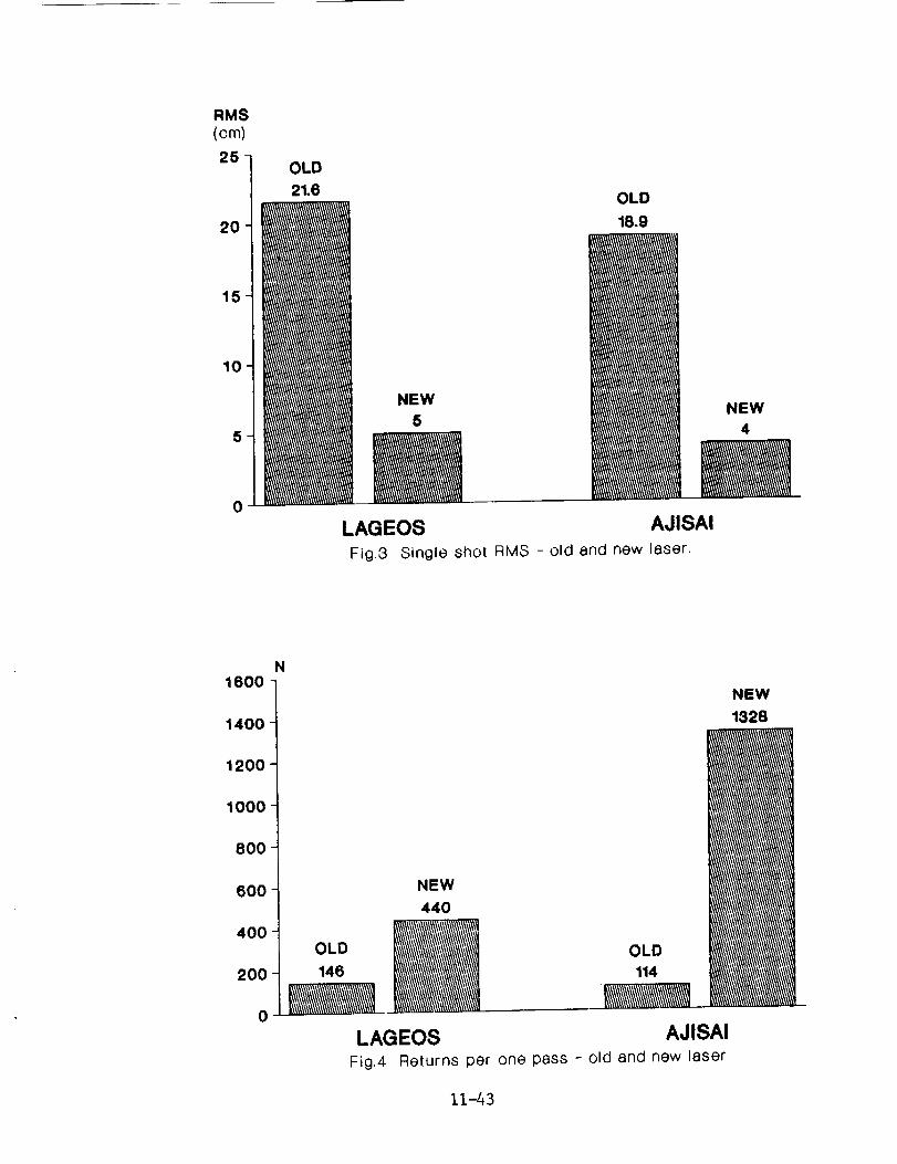
3. Results.
The last pass with old 4 ns laser was performed on August 18,
1991, first pass with new CONTINUUM laser on September 28,
1991. The results of SLR using new laser are shown in Table i.
The table shows results of two periods of activity; I -
October, November, II - December, January. First period was
dedicated to the introducing of new real-time software , second
one to achieve maximum efficiency in actual station
configuration. The last results show that single shot RMS is
equal to 3-5 cm and further increasing of accuracy is limited
by classic photomultiplier RCA 8852 (jitter is about 1 ns).
Maximum number of returns per one pass was about 1500 for
LAGEOS and more than 3000 for _jisai. The Fig.3 and 4 shows the
advantages of new laser in comparison to the old one. To
further improve the single shot RMS the photomultiplier needs
to be changed to a micro-channel plate or an Avalanche
photodiode.
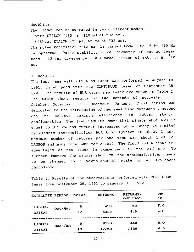
Table I. Results of the observations performed with CONTINUUM
laser from September 28, 1991 to January 31, 1992.
SATELLITE PERIOD PASSES RETI/RNS RETURNS/ RMS
ONE PASS cm
LAGEOS 8 416 52. 7. OOct-Nov
AI I SAI 1 2. 531 3 449 4, 8
8 3516 440 5.0LAGEOS Dec-lan
A/ISAI 13 17288 1328 4.0
11-39
Problems;
- delay of the mount as result of the short steps (100 ms),
step by step mode of the mount should be changed to continuous
mode, problem is especially hard for low satellites as ERS-I,
- small operational memory of old computer limits our
possibility to maximum 2500 returns per pass, also breaks of
about 1 min appeared due to 5 min bursts, microcomputer PC/AT
must be attached for real-time operations.
4. Status and parameters of Borowiec-2 SLR system.
The second SLR system has been installed in Borowiec
Observatory in 1990. The system is destined to place in
Tunisia. The parameters of actua| configuration are presented
in Table 2.
Table 2. The actual parameters (1992) of Borowiec-2 SLR system.
Laser - Nd:YAG
pulse energy - 250 mJ (green)
pulse width - 4 ns
repetition rate - i Hz
Mount - Az-EI computer controlled
tracking - continuous
tracking possibility - low satellites, Lageos, Etalons
encoder resolution - 1.8 arcsec
laser in Coude
Transmitting optics
diameter - 20 cm
gain - 8x
output divergence - 10 arcsec
Receiver - Cassegrain
diameter - 65 cm
diameter of secondary mirror - 20 cm
field of view - 5 arcmin
Guide telescope - Maksutov
diameter - 20 cm
field of view - 1°
11-40
Photomultiplier - RCA 8852
Time Interval Counter - PS-500, 60 ps accuracy
Discriminator - Tennelec 454, or B-6
Time Base - GPS Time Receiver
accuracy - 100 ns
Computer - PC/ATSoftware - Real Time tracking programs, IRVINT and ORBMESS
predictions, initial analysis programs, star programs
language - CCalibration - Pre and Post, externalExpected overall accuracy of the system - ZI5 cm
Operating staff - 2 persons
The current 4 ns laser should be exchanged for the better third
generation system in the near future. System is not yet
operational. The first target calibration is expected this year
and system will be operational at Borowiec in 1993.
5. Localization in Tunisia.
Installation of the SLR station in Tunisia is realized in
cooperation between Office de la Topographie et de la
Cartographie, Tunisie and Space Research Center of Polish
Academy of Sciences. Station will be placed in new geodynamical
center 10 km north from town Medenine in south part of Tunisia.
The Borowiec-2 SLR system will be operational in Tunisia
probably in 1994.
Acknowledgments.
The authors thank technical staff of Borowiec laser group;
Ms. Danuta Schillak, Mr. Wojciech Rzanny and Mr. Stanislaw
Zapasnik for their important participation in new laser
installation and performance of observations.
References.
Schillak S., 1991, Borowiec Laser Station 1986-1990. Artificial
Satellites, Planetary Geodesy, No. 15, Vol. 26, No. i, Warsaw,
Poland, pp. 13-18.
11-41
F_.I OP_T_G P_ODS_ 1990.(284DAYS)
T
LENS M_/'_'/
_ l______v 4#l I pOL_ ¢$CILLAT¢_
TI_LE$CCPE
---OF
CEU.
Fig. 2 LASER Nd : YAG CONT INUUM
11-42
P Y-I:S2
RMS(cm)25
20
15
10
5
0
OLD
21.6
NEW
5
OLD
18.9
LAGEOS AJISAI
Fig.3 Single shot RMS - old and new laser.
NEW4
1600
1400
1200
1000
800
600
400
200
0
N
NEW
440
lo °
LAGEO8FIg,4
OLD
114
AJISAI
Returns per one psss - old and new laser
NEW
1328
11-43
N94-15605
Development of Shanghai Satellite Laser Ranging Station
F.M. Yang, D.T. Tan, C.K. Xiao, W.Z. Chen, J.H. Zhang
Z.P. Zhang, W.H. Lu, Z.Q. Hu, W.F. Tang and J.P. Chen
Shanghai Observatory, Academia Sinica
80 Nandan Road, Shanghai 200030, ChinaTelex: 33164 SHAO CN
Fax: 86-21-4384618
Phone: 86-21-4386191
l. Improvement of the System Hardwares
1.1 Computer control subsystem _i_i:i_;!i_
An IBM/286 computer control system was set up during August 1989 to
March 1990. After three months, the realtlme display of range residuals
(O-C) on the computer screen was completed. Since then, only one
operator has been needed for the routine observation. The operator can
control the whole ranging system by using the computer keyboard during
the observation and can watch the image of the satellite while
illuminated by the sunlight on the monitor of a SIT TV camera side by
side. The system automation and reliability has been greatly improved.
1.2 Laser Subsystem
The Nd:YAG mode-locked laser, which was made by the Shanghai Institute
of Optics and Fine Mechanics and installed at the station in 1986,
contains an oscillator and three single-pass-ampliflers and can usuallyproduce 50 mJ (green) and 180 psec width.
Many work have been done in order to improve the stability on both the
laser beam direction and the output energy. A new chiller was installed
in November 1991 The repetition rate is I-2 Hz for Lageos and Etalon
ranging, and 2-4 Hz for low orbit satellites ranging. The divergence of
the laser is about 0.4 mrad. So, the optimum beam divergence from the
transmitting telescope which has a magnification of 6 is about 13
arcseconds. That is good for Etalon satellites ranging. The divergence
can be adjusted up to 3 arcminutes for the low orblt satellites ranging.
1.3 Receiver
The ordinary PMT (Type GDB49A, China-made) has been adopted from the set
up of the system in 1983 to May 7,1992 when a single photon avalanche
diode (SRAD) receiver made by the Czech Technical University has been
installed. The voltage for the diode is about 30 V and the break down
voltage is about 27.5 V. The field of view of the new receiver is about
45 arcsec. The noise rate of the SPAD working at above condition is200"300 KHz even in [he nighttime.
A 0.15 nm narrow band filter in a theomostat has been tested in
November-December 1991 and has been shown with good performance.
11-44
2. Upgrading of the Softwares
2.1 The prediction of the satellite range
The IRV ephemerides for Lageos and Etalon-l,2 from Texas/CSR, the IRV
for ERS-1 from DGFI and the SAO elements (Kepler orbital elements) for
AJisai and Starlette From NASA/GLTN have been used for the routine
observations. The range residuals of prediction for Lageos is about 5-10
meters by introducing the corrections of the Time-bias (monitored by
ourselves) and UT1 prediction from USNO Bulletin.
2.2 An error model of the tracking mount for reducing the systematic
errors has been built. After the star calibration, the pointing accuracyof the mount is about 5 arcsec.
2.3 On-slte normal point generation
The program of the on-slte normal point generation was finished in March
1992. Since then, these normal polnts of the routlne observation havebeen transmitted to the data centers.
2.4 New pre-processing program
A M-estimate program for better noise rejection purpose has been
developed in stead of the least-squares estimate [Tan Detong, et al,
this proceedings]. The new program has a stronger capability to deal
with those passes which contain more noises and especially with the "endeffect" of the fit curve, it means the noises at the both ends of the
observation curve can be easily edited.
3. The Observation Status
3.1 The summary of the observations
After the above efforts, especially on the system automation, the
performance of the laser ranging has been greatly improved, and the
quantity of the observation passes has been dramatically improved since
July 1990, even in Shanghai--the poor whether area. The observation
staff works pretty hard, 14-16 hours per day and 7 days per week, if the
whether permitting.
" The maximum number of passes obtained in one month 98 passes
(Jan. 1992)
• The maximum number of passes obtained in one night 12 passes
i The maximum number of points obtained in one pass 4265(Eta-2)
2865(Lageos)
" The estimate of range precision (single shot,rms) from 1988---up to
May 7,1992 is about 4-5 cm.
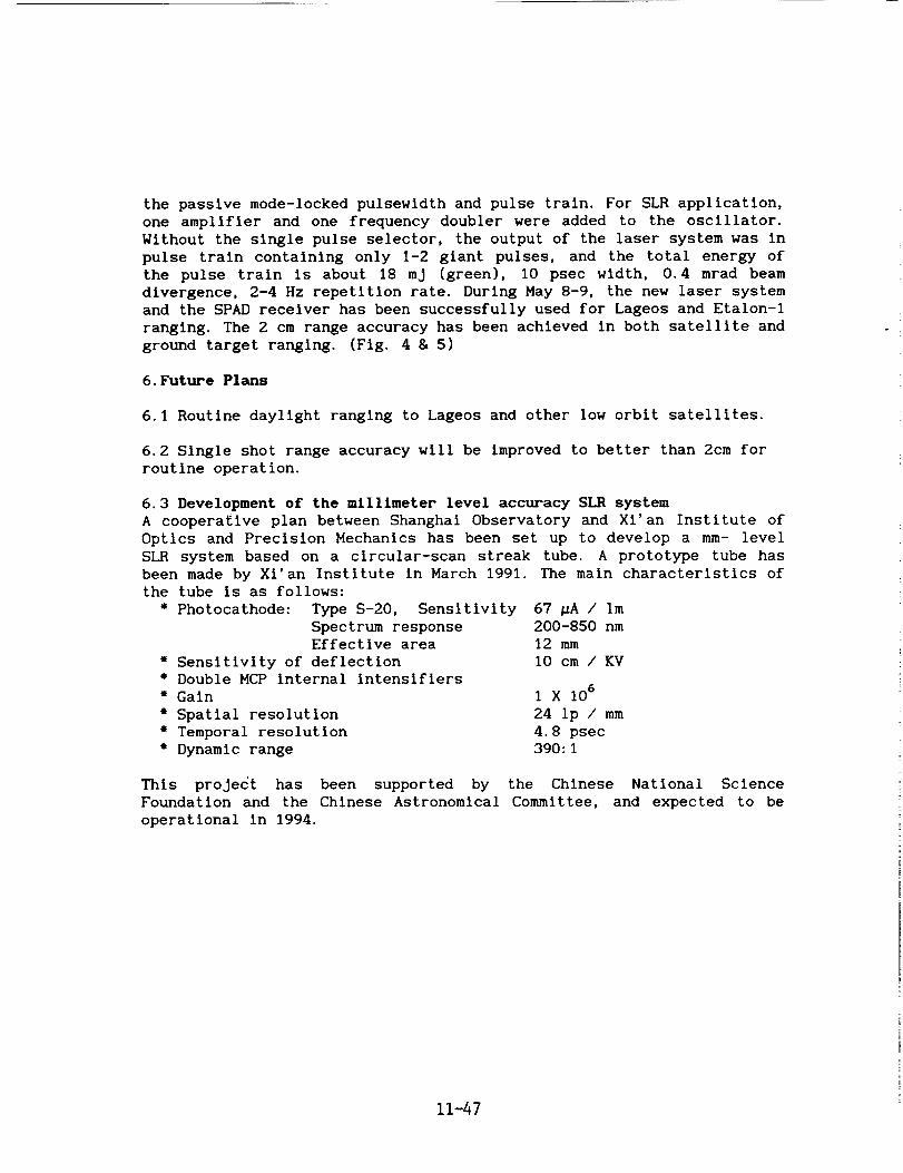
"Fig. l g 2 are the O-C residuals of Etalon-2 and Lageos passes.
11-45
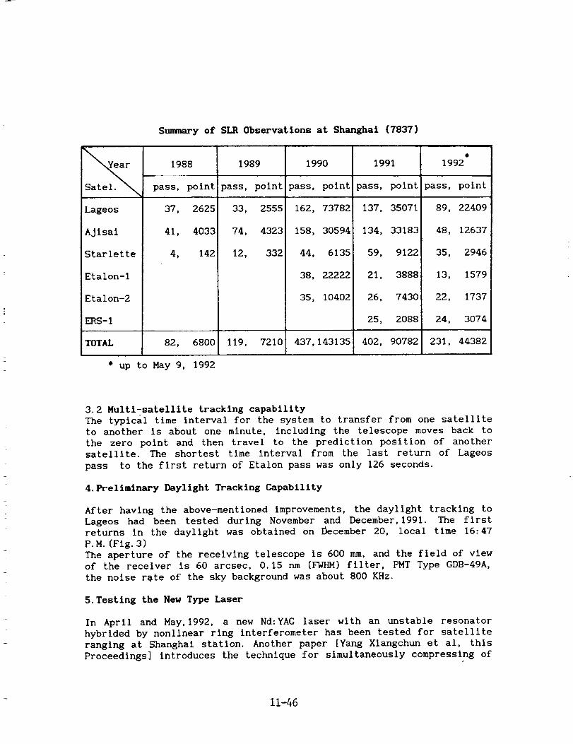
Summary of SIR Observations at Shanghai (7837)
Satel.
Lageos
Ajisal
Starlette
Etalon-1
Etalon-2
ERS-I
1988
pass, polnt
37, 2625
41, 4033
1989 1990 1991
pass, polntlpass, point pass, point
33, 25551 162, 73782 137, 35071
74, 4323 158, 30594 134, 33183
e
1992
pass, point
89, 22409
48, 12637
4, 142 12, 332 44, 6135
38, 22222
35, 10402
59, 9122
21, 3888
26, 7430
25, 2088
35, 2946
13, 1579
22, 1737
24, 3074
TOTAL 82, 6800 119, 7210 437,143135 402, 90782 231, 44382
* up to May 9, 1992
3.2 Multi-satellite tracking capability
The typlcal time interval for the system to transfer from one satellite
to another is about one minute, including the telescope moves back to
the zero point and then travel to the prediction position of another
satellite. The shortest time interval from the last return of Lageos
pass to the first return of Etalon pass was only 126 seconds.
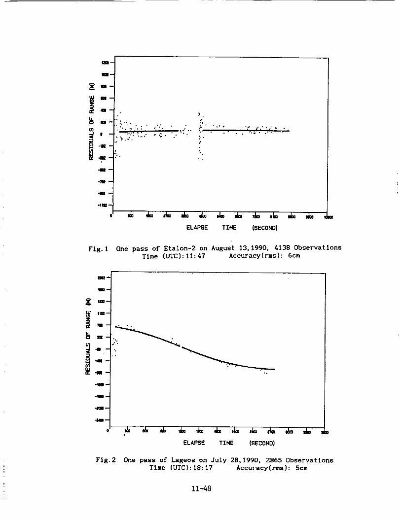
4.Preliminary Daylight Tracking Capability
After having the above-mentioned improvements, the daylight tracking to
Lageos had been tested during November and December, 1991. The first
returns in the daylight was obtained on December 20, local time 16:47
P.M.(FIg. 3)
The aperture of the receiving telescope is 600 mm, and the field of view
of the receiver is 60 arcsec, 0.15 nm (FWHM) filter, PMT Type GDB-49A,
the noise r_te of the sky background was about 800 KHz.
5. Testing the New Type Laser
In April and May, 1992, a new Nd:YAG laser with an unstable resonator
hybrided by nonlinear ring interferometer has been tested for satellite
ranging at Shanghai station. Another paper [Yang Xiangchun et al, this
Proceedings] introduces the technique for simultaneously compressing of
11-46
the passive mode-locked pulsewldth and pulse train. For SLRapplication,one amplifier and one frequency doubler were added to the oscillator.Without the single pulse selector, the output of the laser system was in
pulse train containing only I-2 giant pulses, and the total energy of
the pulse train is about 18 mj (green), I0 psec width, 0.4 mrad beam
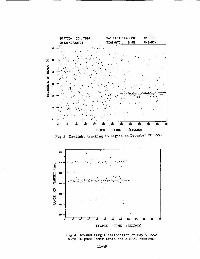
divergence, 2-4 Hz repetition rate. During May 8-9, the new laser system
and the SPAD receiver has been successfully used for Lageos and Etalon-I
ranging. The 2 cm range accuracy has been achieved in both satellite and
ground target ranging. (Fig. 4 & 5)
6. Future Plans
6.1 Routine daylight ranging to Lageos and other low orbit satellites.
6.2 Single shot range accuracy will be improved to better than 2cm for
routine operation.
6.3 Development of the millimeter level accuracy SLR system
A cooperative plan between Shanghai Observatory and Xi'an Institute of
Optics and Precision Mechanics has been set up to develop a mm- level
SLR system based on a circular-scan streak tube. A prototype tube has
been made by Xl'an Institute in March 1991. The main characteristics of
the tube is as follows:
• Photocathode: Type S-20, Sensitivity
Spectrum responseEffective area
" Sensitivity of deflection
• Double MCP internal intensifiers
" Gain
• Spatial resolution
• Temporal resolution
" Dynamic range
67 pA / im200-850 nm
12 mm
l0 cm / KV
1X 10⁶
24 Ip / mm
4.8 psec
390:1
This project has been supported by the Chinese National Science
Foundation and the Chinese Astronomical Committee, and expected to be
operational in 1994.
11-47
m m
mg
u}
i-4 -llm -bq
!
41=--
olU= --
u_ _,o • •
• -...Tv" . _ ._ • •
%
,#
% •
%
"_ ,F' °' • t •" _' '
& • ,A,, _
ELAPSE TIME (SECOND}
Fig. 1 One pass of Etalon-2 on August 13,1990, 4138 ObservationsTime (UTC):11:47 Accuracy(rms): 6cm
-1--
-Nm--
Fig. 2
ELAPSE TIME (SECOND}
One pass of Lageos on July 28,1990, 2865 ObservationsTime (UTC):18:17 Accuracy(rms): 5cm
11-48
m
U_
Ii
Fig. 3
ELAPSE TINE (SECOND)
Daylight tracking to Lageos on December 20, 1991
O_
m
L_o
m
t_
.o.... "9 •. • •°_°° °
°a
a
°
°• •',, .,• o, .- % •
• ° ", • • • • • ° •• ° °'Q", • •
. • .,:._.......,, ,.._'.. ,_ .:,:...._," ._.... :_._,......., •...:..,......_,*.
ELAPSE T I HE ( SECOND )
Fig. 4 Ground target callbratlon on May 9,1992
wlth 10 psec laser train and a SPAD receiver
11-49
STATION ID : 7837
DATA: 05/09/92
SATELLITE: LAGEOS
TINE(UTC): t7: t
i •
r,n
Hul
II
o •
,°
o,
• o
,,;" •.£
".::'.""5/• ;'"_:X,,"
I-
ELAPSE TIME (SECOND)
J- J=
STATION ID :7837
DATA:05/O9/92
SATELLZTE:ETALON-t N" t7g
TIME(UTC): 17:58 RMS=2.3CM
m --
J.
.o . _o. • • %.. o" •
; .,Q.... . q _,,e t ." ....
..._ . •
o. ° ° ""
ELAPSE TIME (SECOND)
ae
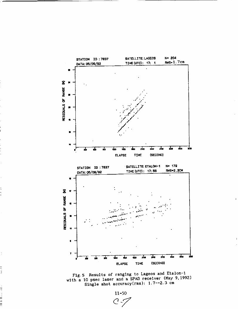
Fig. 5 Results of ranging to Lageos and Etalon-I
with a I0 psec laser and a SPAD receiver (Hay 9,1992)
Single shot accuracy(rms): 1.7--2.3 cm
N94-15606
STATUS-REPORT on WLRS
R. Dassing, W. Schliiter
Institut filr Angewandte Geod_sie
Fundamentalstation Wettzell
D - 8493 KStzting
U. Schreiber*
Forschungseinrichtung Satellitengeod_.sie
Fundamentalstation Wettzell
D - 8493 KStzting
Abstract
The Status-Report of WLRS gives an overview of its set up and the devel-
opments necessary to make the system operational.
1 History
After setting up the new Wettzell laser ranging system WLRS in the year 1989 the systemgot its first successful returns from Lh(;EOS at 29th January, 1990 (see table 1). As these
returns were not calibrated they were only of "engineering use". The system showed
that it was able to track to Etaion-type satellites and to NETEOS/T P2. Before the first
attempts to the moon were started the system was set up to a reliable and calibrated
state. In order to guarantee continous observations from Wettzell a co-location betweenSR$ and WLItS has been carried out. The old SRS-system is now replaced by WLRS.
At the beginning of 1991 WLRS started to track on a routine basis to the satellitesLAGEOS, ETAL01[-1 and ET,tLON-2. During the first six month of year 1991 the WLRS-
System was operated by one shift mostly during night times. Since 1st July 1991 there
were enough educated observers to track 24 hours a day. This can clearly be seen in
the amount of observed passes (see table 1). The number of returns per Lh(lE0S-pass
ranged from several hundred up to 6000. At the end of 1991 the operators had enough
experiences to track AJIS/I, ST/RLETTE and ERS-! satellites.
The first (calibrated) measurements from the moon were obtained in July 1991. InNovember 1991 a series of 52 echos from the moon could be measured, which resulted in
one normalpoint.
°Technische Universit_t Mfinchen, Arcisstr. 21, D - 8000 M_nchen 2
11-51
Jan., 29th, 1990
Feb., 21st, 1990
Feb., 23rd, 190
Oct., 19900ct.1990 - Jan.1991Feb.1991 - Ju1.1991
Ju1.1991 - today:
First echos from LAGEOS
First echos from ETALON-2
First ethos from METEOSAT P2
First echos from APOLLO-15 reflectorCollocation between SRS and _RS
Operational tracking system to LAGEOS, ETALON-1
and ETALON-2 during night time.
Operational tracking system to aH satellites and
to the moon on 24 hours per day.
Table 1: Highlights of setting up WLRS
Month Lunar LAG E-1 F,-2 AJI
01'91 19 402'91 4 1
03'91 2 3 2 -
04'91 7 10 7 -05'91 - 4 9 4 -
06'91 - 13 7 16 -
07'91 1 57 26 19 -
08'91 - 64 33 27 -
09'91 - 49 19 19 -
10'91 - 60 8 17 -11'91 1 18 9 6 -
12'91 - 22 1 2 -
01'92 - 30 1 3" 14
02'92 32 8 7 16
03'92 39 6 9 29
04'92 38 4 6 20
STARL ERS1
1
2
sum
235
7
24
1736
102
125
89
83
3325
46
63
3 86
4 72
Figure 1: Number of passes during 1991 and 1992 of WLRS.
2 Developments
The following modifications and extension were carried out:
• WLR$ is controlled by a HP1000/A900 computer. The observations during 24 hours a
day restricted the computation time for non realtime tasks. Therefor the processing
capacity was extended by an UNIX-based computer HP9000/835. The A900 and
the HPg000 were connected to the local area network (LAN) of the Wettzell station.
• To track low orbiting the realtime software had to he modified:
- To drive the telescope within its full capability under computer control the
telescope driving process needed to be replaced.
- An algorithm was written to drive the telescope "smoothly" into a pass which
already has passed the tracking horizon.
11-52
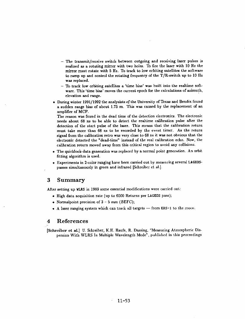
- The transmit/receive switch between outgoing and receiving laser pulses is
realized as a rotating mirror with two holes. To fire the laser with 10 Hz themirror must rotate with 5 Hz. To track to low orbiting satellites the software
to ramp up and control the rotating frequency of the T/R-switch up to 10 Hz
was replaced.
- To track low orbiting satellites a 'time bias' was built into the realtime soft-
ware. This 'time bias' moves the current epoch for the calculations of azimuth,
elevation and range.
• During winter 1991/1992 the analysists of the University of Texas and Bendix found
a sudden range bias of about 1.75 m. This was caused by the replacement of an
amplifier of MCP.The reason was found in the dead time of the detection electronics. The electronic
needs about 68 ns to be able to detect the realtime calibration pulse after the
detection of the start pulse of the laser. This means that the calibration returnmust take more than 68 ns to be recorded by the event timer. As the return
signal from the calibration retro was very close to 68 ns it was not obvious that theelectronic detected the "dead-time" instead of the real calibration echo. Now, the
calibration return moved away from this critical region to avoid any collisions.
• The quicklook-data generation was replaced by a normal point generation. An orbit
fitting algorithm is used.
• Experiments in 2-color ranging have been carried out by measuring several LA6EOS-
passes simultanously in green and infrared [Schreiber et al.].
3 Summary
After setting up WLRS in 1989 some essential modifications were carried out:
• High data acquisition rate (up to fi000 Returns per LAGEOS pass);
• Normalpoint precision of 3 - 5 mm (BEFC);
• A laser ranging system which can track all targets -- from E_tS-1 to the moon.
4 References.+,
[Schrelber et al.] U. Schreiber, K.H. Haufe, R. Dassing, "Measuring Atmospheric Dis-persion With WLRS In Multiple Wavelength Mode", published in this proceedings
11-53
N94-15607
GROUND BASED LASER RANGING
FOR SATELLITE LOCATION
by
G. C. Gilbreath
Optical Systems Section
Naval Center for Space Technology
Naval Research Laboratoryi
and
Harold D. Newby
Malabar Test Facility
Phillips Labs (AFMC)
ABSTRACT
In this article, we describe a new satellite laser ranging
capability which is a joint effort between the Naval Research
Laboratory and Air Force Optical Tracking Facility at Malabar,Florida. Initial measurements off LAGEOS indicates that
uncorrected radial range rms values of 8mm are readily
achievable. Number of photoelectron counts are on the order of
180 which are off by an order of Magnitude from predictedvalues.
I. INTRODUCTION
A new SLR capability designed and implemented by the Naval
Research Laboratory is now operational at the Air Force Optical
Tracking Facility in Malabar, Florida. The configuration is
based on the monostatic design utilized by a number of the NASA
systems in the geoscience network. The laser itself is more
powerful than those used by the NASA network, and electronics are
somewhat different. The system was designed for experimental
efforts in tracking unenhanced satellites (those satellites
without retroreflectors), plumes, and other targets which may or
may not have large laser ranging cross sections.
II. CONFIGURATION
A. Tracking & Acquisition:
Tracking and acquisition was done by the optical tracking
facility at Malabar, Florida. Malabar's facility provided a
bistatic optical acquisition capability when tracking in
"terminator" mode. In this mode, a platform is sunlit but the
tracking station is in the dark. The initial acquisition is done
passively with the 1.22 m aperture telescope. Once trained on
11-54
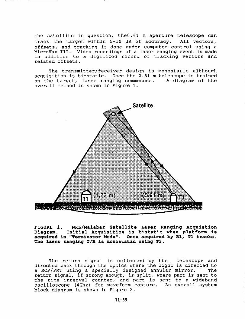
the satellite in question, the0.61 m aperture telescope can
track the target within 5-10 _R of accuracy. All vectors,
offsets, and tracking is done under computer control using a
MicroVax III. Video recordings of a laser ranging event is made
in addition to a digitized record of tracking vectors andrelated offsets.
The transmitter/receiver design is monostatic although
acquisition is bi-static. Once the 0.61 m telescope is trained
on the target, laser ranging commences. A diagram of the
overall method is shown in Figure I.
Satellite
FIGURE 1. NRL/Malabar Satellite Laser Ranging Acquistion
Diagram. Initial Acquisition is bistatic when platform is
acquired in "Terminator Mode". Once acquired by R1, T1 tracks.
The laser ranging T/R is monostatic using T1.
The return signal is collected by the telescope and
directed back through the optics where the light is directed to
a MCP/PMT using a specially designed annular mirror. The
return signal, if strong enough, is split, where part is sent to
the time interval counter, and part is sent to a wideband
oscilloscope (4Ghz) for waveform capture. An overall system
block diagram is shown in Figure 2.
11-55
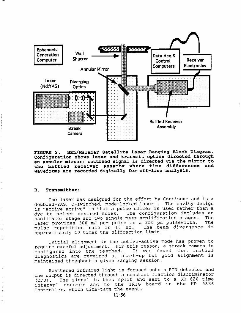
i EphemerisGeneration
Computer
Walli i i =,1
Shutter
Annular Mirror
Laser Diverging
(Nd:YAG) Optics
:::::::
StreakCamera
• o ......
• ° ......
Acq.&Control
)uters
Receiver
Electronics
• • ..... • ..........
• ° , , . , , ° ....
• o , • ........
Baffled Receiver
Assembly
FIGURE 2. NRL/Malabar Satellite Laser Ranging Block Diagram.
Configuration shows laser and transmit optics directed through
an annular mirror; returned signal is directed via the mirror to
the baffled receiver assemby where time differences and
waveforms are recorded digitally for off-line analysis.
B. Transmitter:
The laser was designed for the effort by Continuum and is a
doubled-YAG, Q-switched, mode-locked laser . The cavity design
is "active-active" in that a pulse slicer is used rather than a
dye to select desired modes. The configuration includes an
oscillator stage and two single-pass amplification stages. The
laser provides 300 mJ per pulse in a 250 ps pulsewidth. The
pulse repetition rate is i0 Hz. The beam divergence is
approximately I0 times the diffraction limit.
Initial alignment in the active-active mode has proven to
require careful adjustment. For this reason, a streak camera is
configured into the testbed. It was found that initial
diagnostics are required at start-up but good alignment is
maintained thoughout a given ranging session.
Scattered infrared light is focused onto a PIN detector and
the output is directed through a constant fraction discriminator
(CFD). The signal is then split and sent to a SR 620 time
interval counter and to the IRIG board in the HP 9836
Controller, which time-tags the event.
11-56'
C. Optics :
Adjustable "zoom" optics are installed to vary the
divergence of the beam though computer control. The range of
variability is designed for an output at the antenna of 10_Rad-
100_Rad.
A special annular mirror was designed such that the
transmitted beam passes through a 4.57 cm hole in the 20.32 cm
mirror. The return beam is collimated by the telescope to
present a -11.4 cm beam to the flat. The return beam is then
directed to the baffled receiver assembly.
D. Receiver:
The return signal is directed through a 1 m focal length
lens to a mirror which can be switched in and out of the optical
path. When in place, this mirror directs the light toward aFairchild intensified CCD which enables verification of proper
optical alignment of the receive optics. When this mirror is
switched out, the beam is focused onto a 500mm pinhole and
directed into the gated ITT F4129 PMT/MCP detector. This
detector has a quantum efficiency of 16% with a gain of ~10^6 at
532nm. The detector itself is gated to reduce noise using a
programmable delay/width generator. The gatewidth can vary from
several hundred nanoseconds to I0 _.
The output from the PMT is amplified, inverted, and passed
through a constant fraction discriminator. The output is time-
tagged by the SR 620 time interval counter and the difference
stored in the computer. A portion of the output is also
directed to a Tektronix SCD 5000 4 GHz wideband oscilloscope
which digitizes and stores the waveform for later analysis. A
block diagram of the electronics is shown in Figure 3.
IiI. LAGEOS CALIBRATION
The system was calibrated by ranging off LAGEOS for a
series of passes. Radial RMS ranges (uncorrected) were
estimated to be -8mm using the system. Detected photoelectron
counts were on the order of 50-190. We initially estimated
returns on the order of ii00 p.e.'s. It is possible that the
divergence convolved with pointing accuracy has a greater error
than anticipated. However, scatter loss is most likely to have
been the major contributor to the lower returns.
IV. CONCLUSION
The Naval Research Laboratory and the Air Force Optical
Tracking Facility have installed a new satellite laser ranging
11-57
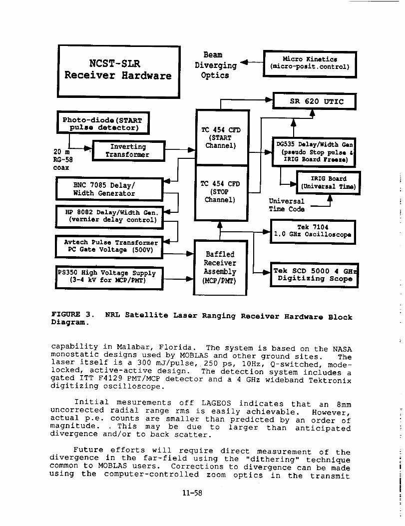
NCST-SLR
Receiver Hardware
Photo-diode (START
pulse detector)
20
RG-58
coax
InvertingTransformer
BNC 7085 Delay/
Width Generator
Beam _ Micro Kinetics IDiverging (micro-posit. control)
Optics
v| SR 620 UTIC
TC 454 CFD
(STARTChannel) DG535 Delay/Width Gen
(pseudo Stop pulse &
IRIG Board Freeze)
HP 8082 Delay/WidthGen.
|PS350 High Voltage Supplyfor _P/PMT)
(3-4 kV
IRIG Board
TC 454 CFD (Universal Time)(STOP
Channel) Universal
Time Code
(vernier delay control) _ Tek 7104
Avtech Pulse Transformer_PC Gate, Voltage (500V) AssemblyBaffledII v__ I'0 eHz Oscill°sc°pe'
Receiver ___Tek SCD 5000 4 GH 4
[ Digitizing Scope]
FIGURE 3.
Diagram.NRL Satellite Laser Ranging Receiver Hardware Block
capability in Malabar, Florida. The system is based on the NASA
monostatic designs used by MOBLAS and other ground sites. The
laser itself is a 300 mJ/pulse, 250 ps, 10Hz, Q-switched, mode-
locked, active-active design. The detection system includes a
gated ITT F4129 PMT/MCP detector and a 4 GHz wideband Tektronixdigitizing oscilloscope.
Initial mesurements off LAGEOS indicates that an 8mm
uncorrected radial range rms is easily achievable. However,
actual p.e. counts are smaller than predicted by an order of
magnitude. This may be due to larger than anticipateddlvergence and/or to back scatter.
Future efforts will require direct measurement of the
divergence in the far-field using the "dithering" technique
common to MOBLAS users. Corrections to divergence can be made
using the computer-controlled zoom optics in the transmit
11-58
optical train. Anticipated experiments will include ranging off
of platforms which may not have enhanced laser ranging cross
sections and ranging off plumes.
V. ACKNOWLEDGMENTS
We would like to thank John Degnan, Tom Varghese, Tom
Zagwodski, and the other NASA personnel who were so generous
with their time and advice. We would also like to acknowledge
the MacDonald Observatory, and especially Jerry Wiant whosesuggestions were invaluable.
We would especially like to acknowledege both the NRL and
Malabar teams, without whose the dedication, hard work, and
creativity, the system could not have been designed, integrated,and calibrated in such a timely manner, including W. C. Collins,
W. L. Lippincott, J. Pirozzoli, T. Murphy, S. Peterson, A.
Clement, J. Kobesky, R. Dasenbrock, R. Betz, T. Knox, M. Baciak,P. Patowski, and R. Orcutt.
11-59
N94-15608
NEW PROGRESS OF RANGING TECHNOLOGY
AT WUHAN SATELLITE LASER RANGING STATION
Xia Zhizhong, Ye Wenwei, Cai qingfu
Institute of Seismology State Seismological Bureau
430071 Wuhan China
ABSTRACT
A satellite laser ranging system with an accuracy of the level of centimeter has been devel-
oped. successfully at the Institute of Seismology, state Seismological Bureau with the coopera-
tion of the Institute of Geodesy and Geophysics, Chinese Academy of Science. With signifi-
cant improvements on the base of the second generation SLR system developed in 1985,rang-
ing accuracy of the new system has been upgraded from 15em to 3-4cm. Measuring range has
also been expanded, so that the ETALON satellite with an orbit height of 20,000Kin launched
by the former U. S. S. R. can now be tracked.
Compared with the 2nd generation ShR system, the newly developed system has the fol-
lowing improvements z
(1) A Q modulated laser is replaced by a mode-locked YAG laser. The new device has a
pulse width of 150ps and a repetition rate of 1-4pps.
(2)A quick response photomultiplier has beer adopted as the receiver for echo, for exam
pie, the adoption of MCP tube has obviously reduced the jitter error of the transit time and
therefore has improved the ranging accuracy.
(3)The whole system is controlled by an IBM.PC/XT Computer to guide automatic track
ing and measurement. It can carry out these functions for satellite orbit caculation, real-time
tracking and adjusting, data acquisition and the preprocessed of observing data etc. , the au
tomatization level and reliability of the observation have improved obviously.
INTRODUCTION
Satellite laser ranging (SLR) is a new measurement technology established with the ad
vancement of laser, optoelectronies, computer, and space science. It has been widely applied in
geoseience. Its observing date have already been used in many scientific fields such as geody
11-60
namics, geodesy, astronomy and earthquake prediction.
It has especially shown its importance in monitoring the movements of global plates and
reglnal crust, determining geocentric coordinates, and studing of earth rotation parameters
and gravitational field model. The 2nd generation SLR system finished in 1985 at the Institute
of Seismology. The system has a measuring range of 8000Kin and the accuracy of 15cm. In
order to upgrade the equipment from 2nd to 3rd generation. So that the observing data of
Wuhan SLR station can meet the need of monitoring crustal movements and the research of
earth rotation parameters and solid earth itself, the' Institute of Seismology and Institute of
Geodesy and Geophysics established cooprative relation.
The 3rd generation system tracked satellite AJISAI of Japan and Lageos of US successful-
ly several times in June 1988. After the preproC,essed of observing data, the accuracy of sin
gle shot attained 5--?cm. Since August 1989, the quick-look data of the ranging results have
been sent to GLTN of NASA. The accuracy of Lageos observing date of Wuhan SLR station
back from GLTN is also about S-6cm.
In April of 1990,F4129 micro-channel plate(MCP) is used to replace PM2233B photo
multiplier and the accuracy reaches 3-4cm. At the same time ETALON-2 and ETALON-1
sateLlite with an orbit height of 20,000Km launched by the former U. S. S.R. in 1989 were.
also observed.
Measuring Principle of System and Performance of the Individual Parts
The ranging principle of the Wuhan SLR system is as follows, the ephmeris(provided by
GLTN or CSR of Teaxs University) is input into an IBM PC computer before observation, in
order to caculate and interpolate the satellite orbit. _Areal-time clock in the computer sends out
a series of order signals to control the automatic tracking of the mount, to shoot laser beam, to
pre-sct range gate, to correct the pointing direction of telescope and range gate in real time and
to collect observing data. At the moment of shooting laser the main pulse is sampled as the
open signal for time interval counter. The echo from the retroreflectors of the satellite is re
ceived by a telescope with an aperture of 60cm. The optical signal is converted to an electronic
pulse by MCP tube and then amplified to close the time interval counter and the time interval
measurement is completed. Meanwhile, observing data is collected by the computer. , The
whole measuring process is shown on the computer display. Observing object,caculating satel-
lite position, or ways of interpolation and measurement can all be selected on the menu. Fig.
1 and Fig. 2 show the telescope and computer, control and electronic measurement system re
spectively. Table 1 is the performance of the main parts in the system.
11-61
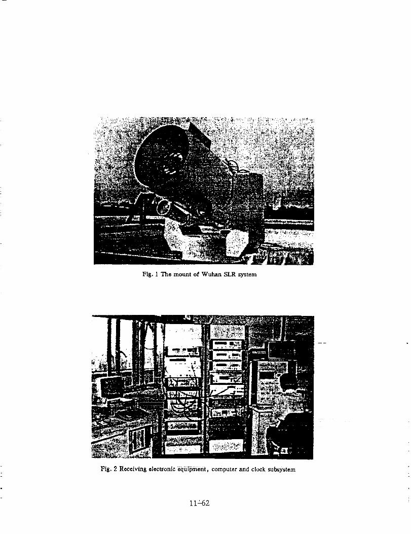
Fig. ] The mount of Wuhan SLR system
Fig. 2 Receiving electronic equipment, computer and clock subsystem
iI_62
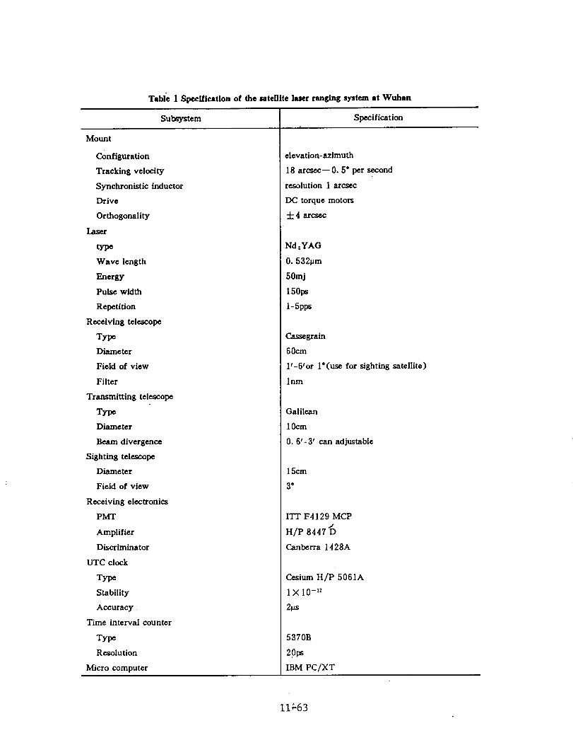
Table 1 Specl/ication of the utelllie laser ranging system at Wuhan
Subsystem
Mount
Configuration
Tracking velocity
Synchronistic inductor
Drive
Orthogonality
Laser
type
Wave length
Energy
Pulse width
Repetition
Receiving telescope
Type
Diameter
Field of view
Filter
Transmitting telescope
Type
Diameter
Beam divergence
Sighting telescope
Diameter
Field of view
Receiving electronics
PMT
Amplifier
Discriminator
UTC clock
Type
Stability
Accuracy
Time interval counter
Type
Resolution
Micro computer
Specification
elevation-azimuth
18 arcsec-- O. 5° per second
resolution 1 arc._ec
DC torque motors
-I-4 arcsec
Nd :YAG
0.532_m
50mj
150ps
1-5pps
Cassegraln
60cm
l'-6'or l'(use for sighting satellite)
lnm
Galilean
10cm
0.6'-3' can adjustable
15cm
3"
ITr F4129 MCP/
H/P 8447 D
Canberra 1428A
Cesium H/P 5061A
1X 10 -12
2Ws
5370B
2.0ps
IBM PC/XT
II_63
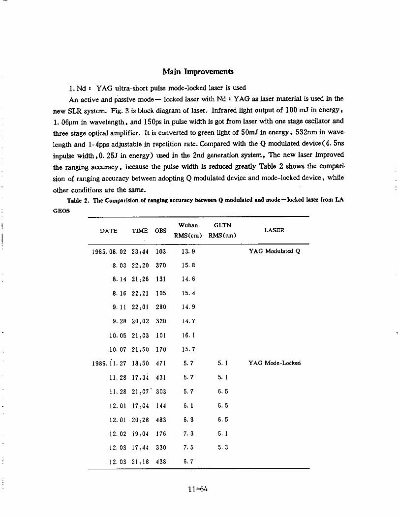
Main Improvements
1. Nd : YAG ultra-short pulse mode-locked laser is used
An active and passive mode-- locked laser with Nd : YAG as laser material is used in the
new SLR system. Fig. 3 is block diagram of laser. Infrared light output of 100 nd in energy,
1.06_m in wavelength, and 150ps in pulse width is got from laser with one stage oscilator and
three stage optical amplifier. It is converted to green light of 50rrd in energy, 532nm in wave
length and 1-4pps adjustable in repetition rate. Compared with the Q modulated device(4.5ns
inpuise width, 0. 25J in energy) used in the 2nd generation system, The new laser improved
the ranging accuracy, because the pulse width is reduced greatly Table 2 shows the compari.
sion of ranging accuracy between adopting Q modulated device and mode-locked device, while
other conditions are the same.
Table 2. The Comparislon of ranging accuracy between Q modulated and mode--locked laser from LA-
GEOS
Wuhan GLTNDATE TIME OBS LASER
RMS(cm) RMS (era)
1985.08.02 23=44 103 13.9
8.03 22:20 370 15.8
8.14 21:26 131 14.6
8.16 22:21 105 15.4
9.11 22:01 280 14.9
9.28 20:02 320 14.7
10.05 21:03 101 16.1
10.07 21:50 170 15.7
1989.11.27 18:50 471 5.7
11.28 17:34 431 5.7
11.28 21:07 _ 303 5.7
12.01 17:04 144 6.1
12.01 20:28 483 6.3
12.02 19:04 176 7.3
12.03 17:44 330 7.5
12.03 21:18 438 6.7
5.1
5.1
6.5
6.5
6.5
5.1
5.3
YAG Modulated Q
YAG Mode-Locked
11-64
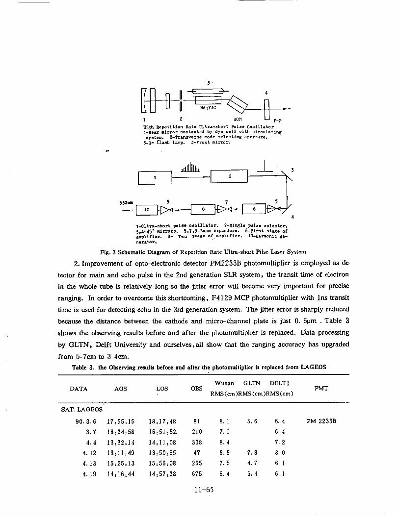
1 2 AOM F-P
High Repet£tfon Rate Ultra-short pulse Oscillator1-Reaxmirror contacted by dye cell wfth circulattr_
system. 2-Transverse mode selectfn_ aperture._-Xe flash lamp. 4-Front mirror.
1 , __C_ -\ _
532_ 9
4
1-Oltra-ehort p_lse oscillator. 2-Slr_le pulse selector.
_p4-45" ec[rrors. 5,7,9-Beam expanders. 6-Plrst sta_e ofamplifier. 8- Two sta_e of amplLffer. IO-Ha-r_onlc ge-nerator.
Fig. 3 Schematic Diagram of Repetition Rate Ultra-short Prise Laser System
2. Improvement of opto-electronie detector PM2233B photomultiplier is employed as de
tector for main and echo pulse in the 2nd generation SLR system, the transit time of electron
in the whole tube is relatively long so the jitter error will become very important for precise
ranging. In order to overcome this shortcoming, F4129 MCP photomultiplier with Ins transit
time is used for detecting echo in the 3rd generation system. The jitter error is sharply reduced
because the distance between the cathode and micro-channel plate is just 0. 6_m . Table 3
shows the observing results before and after the photomultiplier is replaced. Data processing
by GLTN, Delft University and ourselves, all show that the ranging accuracy has upgraded
from 5-Tem to 3-4cm.
Table 3. the Observing results before and after the photomultiplier b replaced from LAGEOS
Wu han GLTN DELT 1DATA AOS LOS OBS PMT
RMS (em)RMS (cm)RMS(cm)
SAT. LAGEOS
90.3.6 17:55:15 18:17:48 81 8.1 5.6 6.4
3.7 16:24:58 16:51:52, 210 7.1 6.4
4.4 13:32:14 14:11:08 308 8.4 7.2
4.12 13:11:49 13:50:55 47 8.8 7.8 8.0
4.13 15:25:13 15:56:08 265 7.5 4.7 6.1
4.19 14z16:44 14z57,38 675 6.4 5.4 6.1
PM2233B
11-65
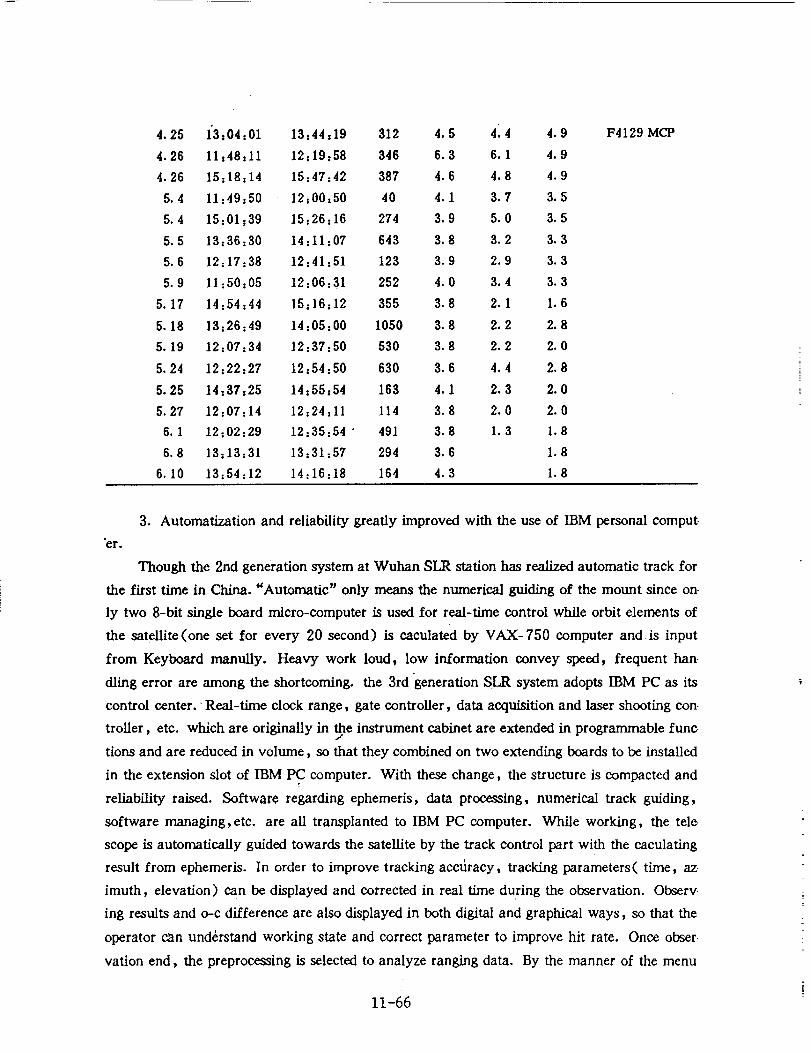
4.25 1"3=04=01 13=44=19 312 4.5 414 4.9
4.26 11=48=11 12=19=58 346 6.3 6.1 4.9
4.26 15=18=14 15=47=42 387 4.6 4.8 4.9
5.4 11=49=50 12:00=50 40 4.1 3.7 3.5
5.4 15=01=39 15:26=16 274 3.9 5.0 3.5
5.5 13=36=30 14=11=07 643 3.8 3.2 3.3
5.6 12=17=38 12=41=51 123 3.9 2.9 3.3
5.9 11:50=05 12:06=31 252 4.0 3.4 3.3
5.17 14=54=44 15=16=12 355 3.8 2.1 1.6
5.18 13=26=49 14=05=00 1050 3.8 2.2 2.8
5.19 12=07=34 12=37=50 530 3.8 2.2 2.0
5.24 12z22=27 12=54=50 630 3.6 4.4 2.8
5.25 14=37=25 14=55=54 163 4.1 2.3 2.0
5.27 12=07=14 12=24=11 114 3.8 2.0 2.0
6.1 12=02=29 12=35:54" 491 3.8 1.3 1.8
6.8 13=13=31 13=31=57 294 3.6 1.8
6.10 13=54=12 14=16=18 164 4.3 1.8
F4129MCP
3. Automatization and reliability greatly improved with the use of IBM personal comput-
"er.
Though the 2rid generation system at Wuhan SLR station has realized automatic track for
the first time in China. "Automatic" only means the numerical guiding of the mount since on
ly two 8-bit single board micro-computer is used for real-time control while orbit elements of
the satellite(one set for every 20 second) is caeulated by VAX-750 computer and is input
from Keyboard manuUy. Heavy work loud, low information convey speed, frequent han
dling error are among the shortcoming, the 3rd 'generation SLR system adopts IBM PC as its
control center. ' Real-time clock range, gate controller, data acquisition and laser shooting con
troller, etc. which are originally in the instrument cabinet are extended in programmable func-J
tions and are reduced in volume, so that they combined on two extending boards to be installed
in the extension slot of IBM PC computer. With these change, the structure is compacted and
reliability raised. Software regarding ephemeris, data processing, numerical track guiding,
software managing,etc, are all transplanted to IBM PC computer. While working, the tele
scope is automatically guided towards the satellite by the track control part with the caculating
result from ephemeris. In order to improve tracking accdracy, tracking parameters( time, az
imuth, elevation) can be displayed and corrected in real time during the observation. Observ
ing results and o-c difference are also displayed in both digital and graphical ways, so that the
operator can understand working state and correct parameter to improve hit rate. Once obser
vation end, the preprocessing is selected to analyze ranging data. By the manner of the menu
11-66
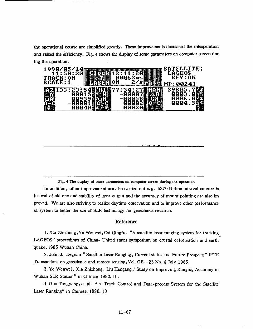
the operational course are simplified greatly. These improvements decreased the misoperation
and raised the efficiency. Fig. 4 shows the display of some parameters on computer screen dur-
ing the operation.
4 ,1- _ _y. _ ._._ • S A T ELL I T E :11:50:20 _ _ 12.11.20 LAGEOS
TRACE: OH _ 00063Ms EEY : ONSCALE: 1 "'_ ON_,,.m..m2_s , MP VV243
_133 23 54._I_'77 54 27'_ 39805:i_
00015B_II - oO_OTm_3m ooo3O0959MH_I]m -0_05811L_ 0006O00011b_..4 00002JP;_4 0004O0040jlm_ 0002 Oj_Jm "
• °. .r .°.r v _.o .- |
Fig. 4 The display of some parameters on computer screen during the operation
In addition, other improvement are also carried out e.g. 5370 B time interval counter is
instead of old one and stability of laser output and the accuracy of mount pointing are also im-
proved. We are also striving to realize daytime observation and to improve other performance
of system to better the use of SLR technology for geoscience research.
Reference
1. Xia Zhizhong,Ye Wenwei,Cai Qingfu. "A satellite laser ranging system for tracking.,t
LAGEOS" proceedings of China- United states symposium on crustal deformation and earth.
quake, 1985 Wuhan China.
2. John J. Degnan "Sateilite Laser Ranging: Current status and Future Prospects" IEEE
Transactions on geoscience and remote sensing,Vol. GE--23 No. 4 July 1985.
3. Ye Wenwei, Xia Zhizhong, Liu Hangang, "Study on Improving Ranging Accuracy in
Wuhan SLR Station" in Chinese 1990. 10.
4. Guo Tangyong, et al. "A Track-Control and Data-process System for the Satellite
Laser Ranging" in Chinese,1990. 10
11-67