Embed Size (px)
Citation preview
Flasher User Guide
Document: UM08022Software Version: 6.36
Revision: 0Date: May 9, 2019
A product of SEGGER Microcontroller GmbH
www.segger.com
2
Disclaimer
Specifications written in this document are believed to be accurate, but are not guaranteed tobe entirely free of error. The information in this manual is subject to change for functional orperformance improvements without notice. Please make sure your manual is the latest edition.While the information herein is assumed to be accurate, SEGGER Microcontroller GmbH (SEG-GER) assumes no responsibility for any errors or omissions. SEGGER makes and you receive nowarranties or conditions, express, implied, statutory or in any communication with you. SEGGERspecifically disclaims any implied warranty of merchantability or fitness for a particular purpose.
Copyright notice
You may not extract portions of this manual or modify the PDF file in any way without the priorwritten permission of SEGGER. The software described in this document is furnished under alicense and may only be used or copied in accordance with the terms of such a license.
© 2004-2019 SEGGER Microcontroller GmbH, Monheim am Rhein / Germany
Trademarks
Names mentioned in this manual may be trademarks of their respective companies.
Brand and product names are trademarks or registered trademarks of their respective holders.
Contact address
SEGGER Microcontroller GmbH
Ecolab-Allee 5D-40789 Monheim am Rhein
Germany
Tel. +49-2173-99312-0Fax. +49-2173-99312-28E-mail: [email protected]: www.segger.com
Flasher User Guide (UM08022) © 2004-2019 SEGGER Microcontroller GmbH

3
Manual versions
This manual describes the Flasher device. For further information on topics or routines not yetspecified, please contact us.
Print date: May 9, 2019
Manualversion
Revision Date By Description
6.36 0 190509 MF added Portable PLUS specific section in multiple-file chapter for clarification
6.34 3 190221 MF updated chapter Batch Programming in stand-alone mode
6.34 2 180205 AB
Removed all Flasher ATE related topics.* Content has been moved to UM08035_FlasherATE.pdfChapter “Hardware”* Added safety disclaimer for JTAG isolator
6.32 2 180205 AB Chapter “Working with Flasher”* Added STM8 support to universal flash loader.
6.30 1 180222 AG Chapter “Working with Flasher”* Section “Custom labels” added.
6.20 1 171130 ABChapter “Working with Flasher”* Section “Flasher ATE” added.Added chapter “TCP Services”
6.20 0 171121 AB Chapter “Working with Flasher”* Section “Flasher Portable PLUS” added.
6.10a 0 160922 EL Chapter “Introduction”* Section “Flasher Portable” updated.
6.00 0 160715 NG Chapter “Working with Flasher”* Section “Batch Programming” added.
5.12e 0 160511 NGChapter “Working with Flasher”* Section “Setting up Flasher for stand-alone mode” moved.* Section “Preparing for stand-alone operation manually” added.
5.02f 0 151023 RH Chapter “Remote control”* Section “General usage” addded.
5.02e 0 151021 EL Chapter “Introduction”* Section “Specifications” updated for all models.
5.02f 0 151014 RH Chapter “Working with Flasher”* Section “Programming multiple targets” addded.
4.50c 0 150611 EL Chapter “Working with Flasher”* Section “Programming multiple targets in parallel” addded.
4.98 0 150205 AG
Chapter “Working with Flasher”* Section “Authorized flashing” added.* Section “Limiting the number of programming cycles” added.* Section “Operating Modes” updated.
4.86 0 140610 AG Chapter “Working with Flasher”* Section “Newline encoding” added.
4.80 1 131220 AG Chapter “Working with Flasher”* Section “Multiple File Support” updated.
4.80 0 131031 ELChapter “Remote control”* Section “Commands to Flasher” updated.“#FCRC” command added.
4.78 0 130917 AG
Chapter “Introduction”* Section “Features of Flasher Portable” added.Chapter “Working with Flasher”* Section “Flasher Portable” added.* Section “Multiple File Support” updated.
4.72 0 130612 EL Chapter “Working with Flasher”* Section “Patch file support” added.
4.64a 0 130226 EL Chapter “Working with Flasher”* Section “LED status indicators” updated.
4.63a 0 130131 ELChapter “Remote Control”* Section “ASCII command interface”Chapter “ASCII interface via Telnet” added.
Flasher User Guide (UM08022) © 2004-2019 SEGGER Microcontroller GmbH
4
Manualversion
Revision Date By Description
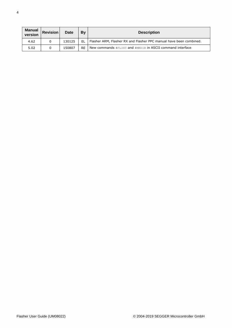
4.62 0 130125 EL Flasher ARM, Flasher RX and Flasher PPC manual have been combined.
5.02 0 150807 RE New commands #FLIST and #MKDIR in ASCII command interface
Flasher User Guide (UM08022) © 2004-2019 SEGGER Microcontroller GmbH
5
About this document
Assumptions
This document assumes that you already have a solid knowledge of the following:• The software tools used for building your application (assembler, linker, C compiler).• The C programming language.• The target processor.• DOS command line.
If you feel that your knowledge of C is not sufficient, we recommend The C Programming Lan-guage by Kernighan and Richie (ISBN 0–13–1103628), which describes the standard in C pro-gramming and, in newer editions, also covers the ANSI C standard.
How to use this manual
This manual explains all the functions and macros that the product offers. It assumes you havea working knowledge of the C language. Knowledge of assembly programming is not required.
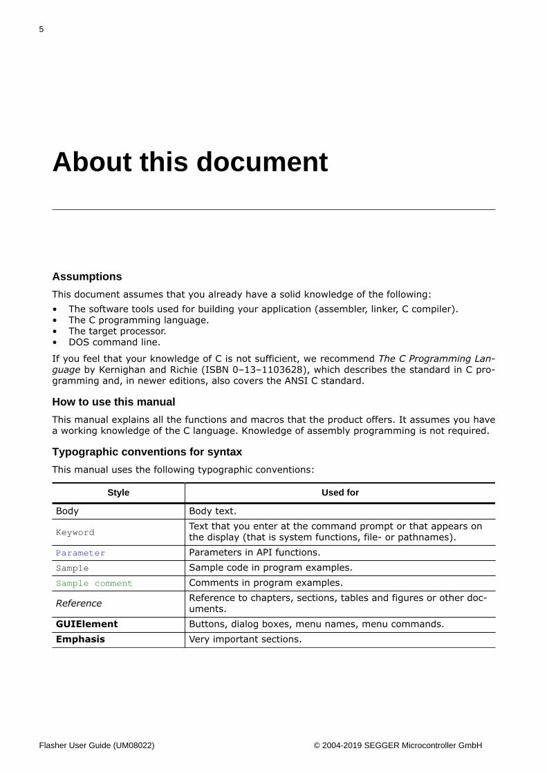
Typographic conventions for syntax
This manual uses the following typographic conventions:
Style Used for
Body Body text.
KeywordText that you enter at the command prompt or that appears onthe display (that is system functions, file- or pathnames).
Parameter Parameters in API functions.Sample Sample code in program examples.Sample comment Comments in program examples.
Reference Reference to chapters, sections, tables and figures or other doc-uments.
GUIElement Buttons, dialog boxes, menu names, menu commands.Emphasis Very important sections.
Flasher User Guide (UM08022) © 2004-2019 SEGGER Microcontroller GmbH

6
Flasher User Guide (UM08022) © 2004-2019 SEGGER Microcontroller GmbH
7
Table of contents
1 Introduction ..................................................................................................................10
1.1 Flasher overview ..........................................................................................111.1.1 Features of Flasher ARM/PPC/RX/PRO .................................................. 111.1.2 Features of Flasher Portable/Flasher Portable PLUS ................................ 111.1.3 Working environment .........................................................................12
1.2 Specifications ...............................................................................................131.2.1 Specifications for Flasher ARM ............................................................ 131.2.2 Specifications for Flasher RX .............................................................. 151.2.3 Specifications for Flasher PPC ............................................................. 171.2.4 Specifications for Flasher PRO .............................................................191.2.5 Specifications for Flasher Portable PLUS ............................................... 221.2.6 Specifications for Flasher Portable ....................................................... 25
2 Working with Flasher .................................................................................................. 28
2.1 Flasher Portable PLUS ...................................................................................292.1.1 Housing & Buttons ............................................................................ 292.1.2 Configuration .................................................................................... 30
2.2 Flasher Portable ........................................................................................... 312.2.1 Housing & Buttons ............................................................................ 31
2.3 File system ..................................................................................................332.4 Setting up the IP interface ............................................................................34
2.4.1 Connecting the first time ................................................................... 342.5 Operating modes ......................................................................................... 35
2.5.1 J-Link mode ..................................................................................... 352.5.2 Stand-alone mode .............................................................................362.5.3 MSD mode ....................................................................................... 38
2.6 Setting up Flasher for stand-alone mode .........................................................392.6.1 Preparing for stand-alone operation manually ....................................... 42
2.7 Universal Flash Loader mode .........................................................................442.7.1 Preparing manually ........................................................................... 442.7.2 Preparing using the PC utility ............................................................. 51
2.8 Multiple File Support .....................................................................................522.8.1 Flasher Portable specifics ................................................................... 522.8.2 Flasher Portable PLUS specifics ........................................................... 53
2.9 Custom labels ..............................................................................................552.9.1 Hardware and software requirements .................................................. 552.9.2 Assigning labels ................................................................................ 552.9.3 Considerations .................................................................................. 56
2.10 Programming multiple targets ...................................................................... 572.10.1 Programming multiple targets with J-Flash ......................................... 57
Flasher User Guide (UM08022) © 2004-2019 SEGGER Microcontroller GmbH
8
2.11 Batch Programming in stand-alone mode ...................................................... 582.11.1 Flasher Portable specifics ..................................................................592.11.2 Examples ........................................................................................60
2.12 Serial number programming ........................................................................ 612.12.1 Serial number settings ..................................................................... 612.12.2 Serial number file ............................................................................622.12.3 Serial number list file ...................................................................... 622.12.4 Programming process .......................................................................632.12.5 Downloading serial number files to Flasher ......................................... 642.12.6 Sample setup ..................................................................................64
2.13 Patch file support ....................................................................................... 662.14 Limiting the number of programming cycles .................................................. 67
2.14.1 Changed fail/error LED indicator behavior ...........................................672.14.2 Required Flasher hardware version for Cntdown.txt support .................. 67
2.15 Authorized flashing ..................................................................................... 682.15.1 Creating / Adding the secure area ..................................................... 682.15.2 Moving files to the secure area ......................................................... 682.15.3 Considerations to be taken when using the secure area ........................ 692.15.4 Required Flasher hardware version .................................................... 69
2.16 Target interfaces ........................................................................................ 702.17 Supported microcontrollers .......................................................................... 71
2.17.1 Flasher ...........................................................................................712.18 Support of external flashes ..........................................................................72
2.18.1 Flasher ARM ................................................................................... 722.18.2 Flasher RX ......................................................................................722.18.3 Flasher PPC .................................................................................... 72
2.19 Supported cores .........................................................................................732.19.1 Flasher ARM ................................................................................... 732.19.2 Flasher RX ......................................................................................732.19.3 Flasher PPC .................................................................................... 73
2.20 Newline encoding ....................................................................................... 742.21 Programming multiple targets in parallel ....................................................... 75
3 TCP Services .............................................................................................................. 76
3.1 FTP Server .................................................................................................. 773.1.1 Access data ......................................................................................77
3.2 Web server ..................................................................................................78
4 Remote control ............................................................................................................79
4.1 Overview .....................................................................................................804.2 Handshake control ....................................................................................... 814.3 ASCII command interface ............................................................................. 82
4.3.1 Introduction ......................................................................................824.3.2 General command and reply message format ....................................... 824.3.3 General usage .................................................................................. 824.3.4 Settings for ASCII interface via RS232 .................................................824.3.5 Settings for ASCII interface via Telnet ................................................. 824.3.6 Commands and replies ...................................................................... 83
5 Performance ................................................................................................................91
5.1 Performance of MCUs with internal flash memory .............................................925.1.1 Flasher ARM ..................................................................................... 925.1.2 Flasher RX ....................................................................................... 925.1.3 Flasher PPC ...................................................................................... 92
6 Hardware .....................................................................................................................93
6.1 Flasher ARM 20-pin JTAG/SWD Connector ....................................................... 946.1.1 Pinout JTAG ......................................................................................94
Flasher User Guide (UM08022) © 2004-2019 SEGGER Microcontroller GmbH
9
6.1.2 Pinout SWD ......................................................................................956.1.3 Target power supply .......................................................................... 96
6.2 Flasher RX 14-pin connector ..........................................................................976.2.1 Target power supply .......................................................................... 98
6.3 Flasher PPC 14-pin connector ........................................................................ 996.4 Target board design ....................................................................................100
6.4.1 Pull-up/pull-down resistors ............................................................... 1006.4.2 RESET, nTRST ................................................................................. 100
6.5 Adapters ................................................................................................... 1016.5.1 JTAG Isolator .................................................................................. 1016.5.2 J-Link Needle Adapter ......................................................................102
6.6 How to determine the hardware version ........................................................104
7 Support and FAQs ....................................................................................................105
7.1 Contacting support ..................................................................................... 1067.2 Frequently Asked Questions .........................................................................107
8 Background information ............................................................................................ 108
8.1 Flash programming .....................................................................................1098.1.1 How does flash programming via Flasher work? ...................................1098.1.2 Data download to RAM .....................................................................1098.1.3 Available options for flash programming ............................................. 1098.1.4 How does the universal flash programming work? ................................109
9 Glossary .................................................................................................................... 110
10 Literature and references ........................................................................................114
Flasher User Guide (UM08022) © 2004-2019 SEGGER Microcontroller GmbH
Chapter 1 Introduction
This chapter gives a short overview about the different models of the Flasher family andtheir features.
Flasher User Guide (UM08022) © 2004-2019 SEGGER Microcontroller GmbH
11 CHAPTER 1 Flasher overview
1.1 Flasher overviewFlasher is a programming tool for microcontrollers with on-chip or external flash memory.Flasher is designed for programming flash targets with the J-Flash software or stand-alone.In addition to that Flasher can also be used as a regular J-Link. For more information aboutJ-Link in general, please refer to the J-Link / J-Trace User Guide which can be downloadedat http://www.segger.com.
Flasher connects to a PC using the USB/Ethernet/RS232 interface (what host interfaces areavailable depends on the Flasher model), running Microsoft Windows 2000, Windows XP,Windows 2003, Windows Vista, Windows 7 or Windows 8. In stand-alone mode, Flasher canbe driven by the start/stop button, or via the RS232 interface (handshake control or ASCIIinterface). Flasher always has a 20-pin connector, which target interfaces are supporteddepends on the Flasher model:• Flasher ARM: JTAG and SWD are supported.• Flasher RX: JTAG is supported. Flasher comes with additional 14-pin RX adapter• Flasher PPC: JTAG is supported. Flasher comes with additional 14-pin PPC adapter.• Flasher PRO: JTAG and SWD are supported.
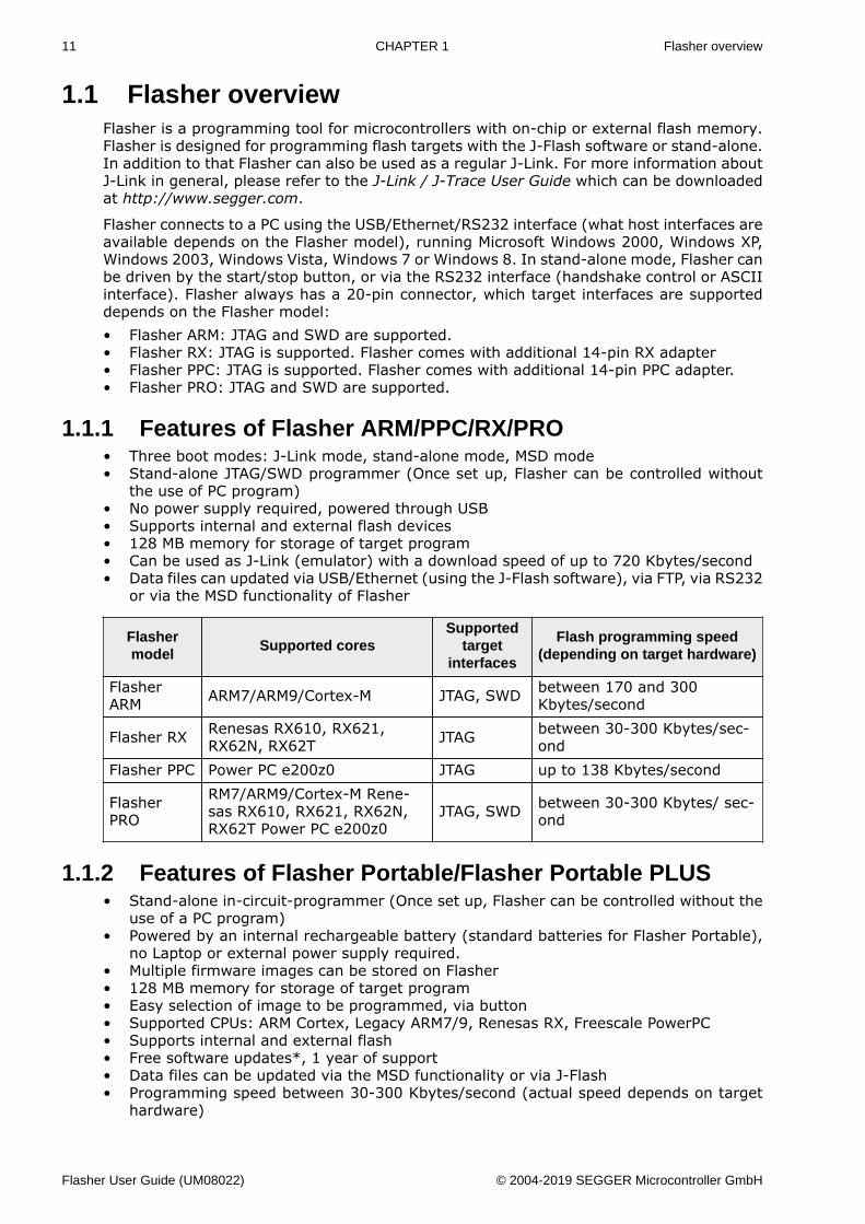
1.1.1 Features of Flasher ARM/PPC/RX/PRO• Three boot modes: J-Link mode, stand-alone mode, MSD mode• Stand-alone JTAG/SWD programmer (Once set up, Flasher can be controlled without
the use of PC program)• No power supply required, powered through USB• Supports internal and external flash devices• 128 MB memory for storage of target program• Can be used as J-Link (emulator) with a download speed of up to 720 Kbytes/second• Data files can updated via USB/Ethernet (using the J-Flash software), via FTP, via RS232
or via the MSD functionality of Flasher
Flashermodel
Supported coresSupported
targetinterfaces
Flash programming speed(depending on target hardware)
FlasherARM ARM7/ARM9/Cortex-M JTAG, SWD between 170 and 300
Kbytes/second
Flasher RX Renesas RX610, RX621,RX62N, RX62T JTAG between 30-300 Kbytes/sec-
ondFlasher PPC Power PC e200z0 JTAG up to 138 Kbytes/second
FlasherPRO
RM7/ARM9/Cortex-M Rene-sas RX610, RX621, RX62N,RX62T Power PC e200z0
JTAG, SWD between 30-300 Kbytes/ sec-ond
1.1.2 Features of Flasher Portable/Flasher Portable PLUS• Stand-alone in-circuit-programmer (Once set up, Flasher can be controlled without the
use of a PC program)• Powered by an internal rechargeable battery (standard batteries for Flasher Portable),
no Laptop or external power supply required.• Multiple firmware images can be stored on Flasher• 128 MB memory for storage of target program• Easy selection of image to be programmed, via button• Supported CPUs: ARM Cortex, Legacy ARM7/9, Renesas RX, Freescale PowerPC• Supports internal and external flash• Free software updates*, 1 year of support• Data files can be updated via the MSD functionality or via J-Flash• Programming speed between 30-300 Kbytes/second (actual speed depends on target
hardware)
Flasher User Guide (UM08022) © 2004-2019 SEGGER Microcontroller GmbH
12 CHAPTER 1 Flasher overview
Note
Ethernet and RS232 as host interface are not available for Flasher Portable
Note
*As a legitimate owner of a SEGGER Flasher, you can always download the latestsoftware free of charge. Though not planned and not likely, we reserve the right tochange this policy. Note that older models may not be supported by newer versionsof the software. Typically, we support older models with new software at least 3 yearsafter end of life
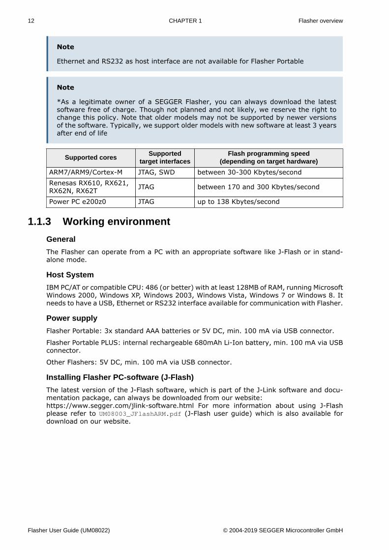
Supported coresSupported
target interfacesFlash programming speed
(depending on target hardware)
ARM7/ARM9/Cortex-M JTAG, SWD between 30-300 Kbytes/secondRenesas RX610, RX621,RX62N, RX62T JTAG between 170 and 300 Kbytes/second
Power PC e200z0 JTAG up to 138 Kbytes/second
1.1.3 Working environment
General
The Flasher can operate from a PC with an appropriate software like J-Flash or in stand-alone mode.
Host System
IBM PC/AT or compatible CPU: 486 (or better) with at least 128MB of RAM, running MicrosoftWindows 2000, Windows XP, Windows 2003, Windows Vista, Windows 7 or Windows 8. Itneeds to have a USB, Ethernet or RS232 interface available for communication with Flasher.
Power supply
Flasher Portable: 3x standard AAA batteries or 5V DC, min. 100 mA via USB connector.
Flasher Portable PLUS: internal rechargeable 680mAh Li-Ion battery, min. 100 mA via USBconnector.
Other Flashers: 5V DC, min. 100 mA via USB connector.
Installing Flasher PC-software (J-Flash)
The latest version of the J-Flash software, which is part of the J-Link software and docu-mentation package, can always be downloaded from our website:https://www.segger.com/jlink-software.html For more information about using J-Flashplease refer to UM08003_JFlashARM.pdf (J-Flash user guide) which is also available fordownload on our website.
Flasher User Guide (UM08022) © 2004-2019 SEGGER Microcontroller GmbH
13 CHAPTER 1 Specifications
1.2 Specifications
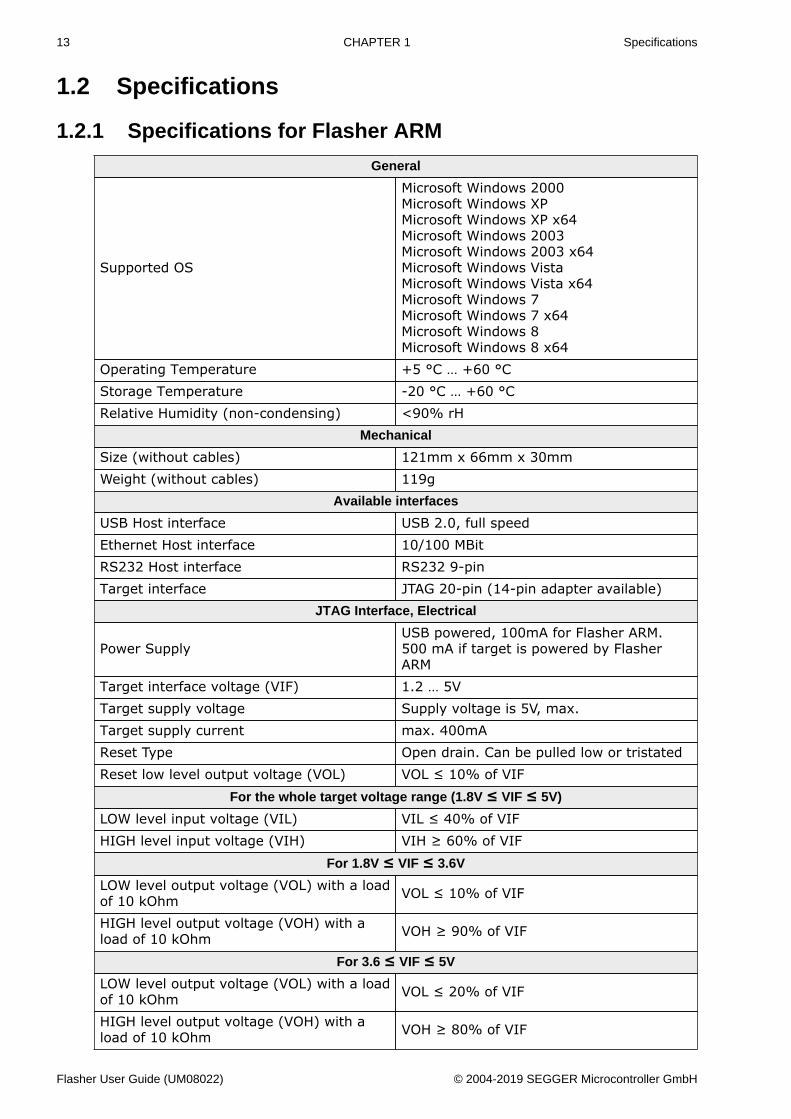
1.2.1 Specifications for Flasher ARM
General
Supported OS
Microsoft Windows 2000Microsoft Windows XPMicrosoft Windows XP x64Microsoft Windows 2003Microsoft Windows 2003 x64Microsoft Windows VistaMicrosoft Windows Vista x64Microsoft Windows 7Microsoft Windows 7 x64Microsoft Windows 8Microsoft Windows 8 x64
Operating Temperature +5 °C … +60 °CStorage Temperature -20 °C … +60 °CRelative Humidity (non-condensing) <90% rH
Mechanical
Size (without cables) 121mm x 66mm x 30mmWeight (without cables) 119g
Available interfaces
USB Host interface USB 2.0, full speedEthernet Host interface 10/100 MBitRS232 Host interface RS232 9-pinTarget interface JTAG 20-pin (14-pin adapter available)
JTAG Interface, Electrical
Power SupplyUSB powered, 100mA for Flasher ARM.500 mA if target is powered by FlasherARM
Target interface voltage (VIF) 1.2 … 5VTarget supply voltage Supply voltage is 5V, max.Target supply current max. 400mAReset Type Open drain. Can be pulled low or tristatedReset low level output voltage (VOL) VOL ≤ 10% of VIF
For the whole target voltage range (1.8V ≤ VIF ≤ 5V)
LOW level input voltage (VIL) VIL ≤ 40% of VIFHIGH level input voltage (VIH) VIH ≥ 60% of VIF
For 1.8V ≤ VIF ≤ 3.6V
LOW level output voltage (VOL) with a loadof 10 kOhm VOL ≤ 10% of VIF
HIGH level output voltage (VOH) with aload of 10 kOhm VOH ≥ 90% of VIF
For 3.6 ≤ VIF ≤ 5V
LOW level output voltage (VOL) with a loadof 10 kOhm VOL ≤ 20% of VIF
HIGH level output voltage (VOH) with aload of 10 kOhm VOH ≥ 80% of VIF
Flasher User Guide (UM08022) © 2004-2019 SEGGER Microcontroller GmbH
14 CHAPTER 1 Specifications
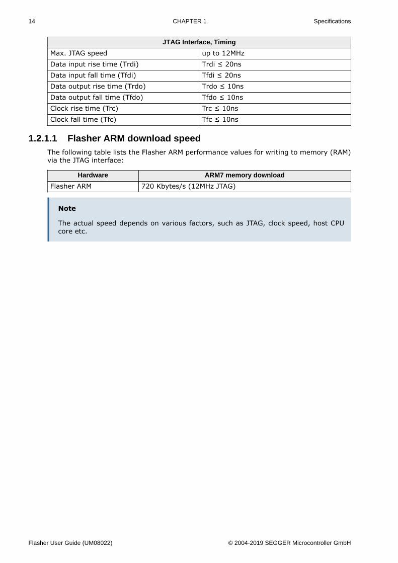
JTAG Interface, Timing
Max. JTAG speed up to 12MHzData input rise time (Trdi) Trdi ≤ 20nsData input fall time (Tfdi) Tfdi ≤ 20nsData output rise time (Trdo) Trdo ≤ 10nsData output fall time (Tfdo) Tfdo ≤ 10nsClock rise time (Trc) Trc ≤ 10nsClock fall time (Tfc) Tfc ≤ 10ns
1.2.1.1 Flasher ARM download speedThe following table lists the Flasher ARM performance values for writing to memory (RAM)via the JTAG interface:
Hardware ARM7 memory download
Flasher ARM 720 Kbytes/s (12MHz JTAG)
Note
The actual speed depends on various factors, such as JTAG, clock speed, host CPUcore etc.
Flasher User Guide (UM08022) © 2004-2019 SEGGER Microcontroller GmbH
15 CHAPTER 1 Specifications
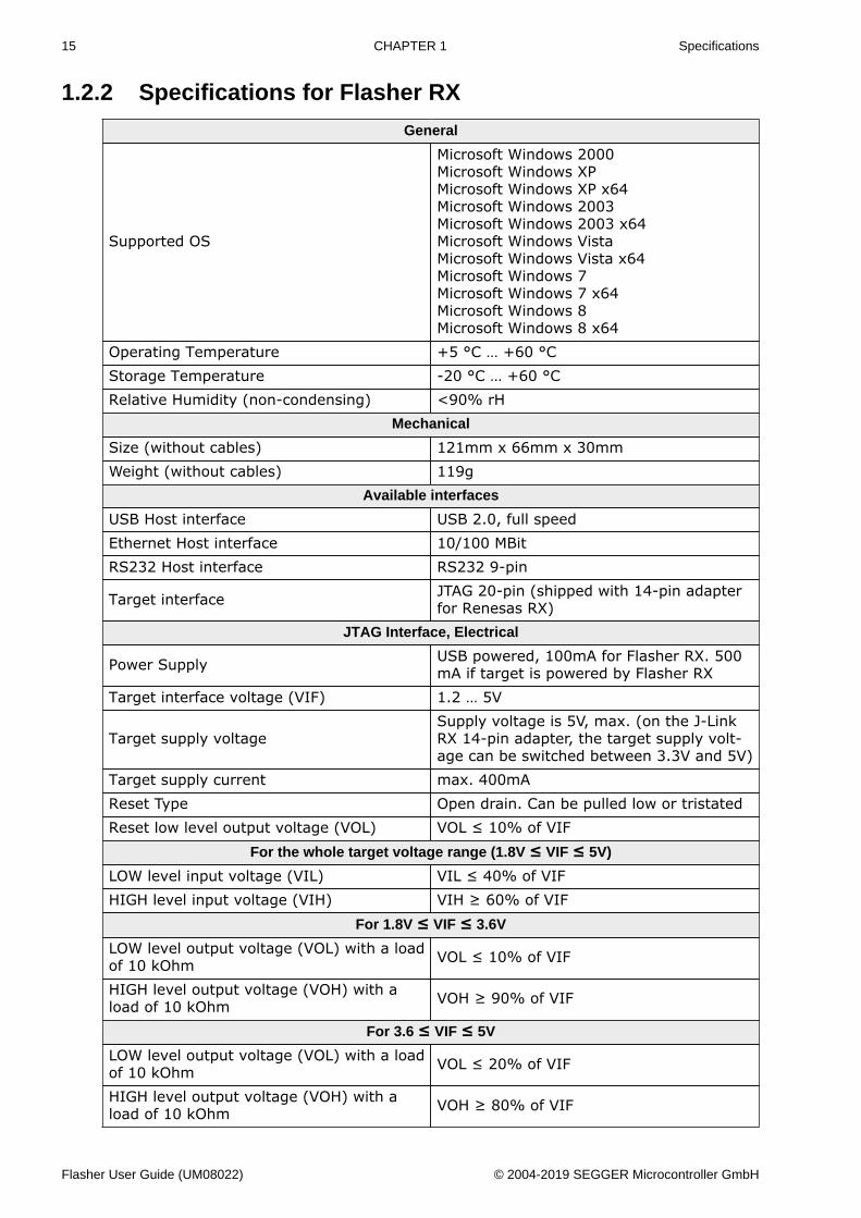
1.2.2 Specifications for Flasher RX
General
Supported OS
Microsoft Windows 2000Microsoft Windows XPMicrosoft Windows XP x64Microsoft Windows 2003Microsoft Windows 2003 x64Microsoft Windows VistaMicrosoft Windows Vista x64Microsoft Windows 7Microsoft Windows 7 x64Microsoft Windows 8Microsoft Windows 8 x64
Operating Temperature +5 °C … +60 °CStorage Temperature -20 °C … +60 °CRelative Humidity (non-condensing) <90% rH
Mechanical
Size (without cables) 121mm x 66mm x 30mmWeight (without cables) 119g
Available interfaces
USB Host interface USB 2.0, full speedEthernet Host interface 10/100 MBitRS232 Host interface RS232 9-pin
Target interface JTAG 20-pin (shipped with 14-pin adapterfor Renesas RX)
JTAG Interface, Electrical
Power Supply USB powered, 100mA for Flasher RX. 500mA if target is powered by Flasher RX
Target interface voltage (VIF) 1.2 … 5V
Target supply voltageSupply voltage is 5V, max. (on the J-LinkRX 14-pin adapter, the target supply volt-age can be switched between 3.3V and 5V)
Target supply current max. 400mAReset Type Open drain. Can be pulled low or tristatedReset low level output voltage (VOL) VOL ≤ 10% of VIF
For the whole target voltage range (1.8V ≤ VIF ≤ 5V)
LOW level input voltage (VIL) VIL ≤ 40% of VIFHIGH level input voltage (VIH) VIH ≥ 60% of VIF
For 1.8V ≤ VIF ≤ 3.6V
LOW level output voltage (VOL) with a loadof 10 kOhm VOL ≤ 10% of VIF
HIGH level output voltage (VOH) with aload of 10 kOhm VOH ≥ 90% of VIF
For 3.6 ≤ VIF ≤ 5V
LOW level output voltage (VOL) with a loadof 10 kOhm VOL ≤ 20% of VIF
HIGH level output voltage (VOH) with aload of 10 kOhm VOH ≥ 80% of VIF
Flasher User Guide (UM08022) © 2004-2019 SEGGER Microcontroller GmbH

16 CHAPTER 1 Specifications
JTAG Interface, Timing
Max. JTAG speed up to 12MHzData input rise time (Trdi) Trdi ≤ 20nsData input fall time (Tfdi) Tfdi ≤ 20nsData output rise time (Trdo) Trdo ≤ 10nsData output fall time (Tfdo) Tfdo ≤ 10nsClock rise time (Trc) Trc ≤ 10nsClock fall time (Tfc) Tfc ≤ 10ns
1.2.2.1 Flasher RX download speedThe following table lists the Flasher RX performance values for writing to memory (RAM)via the JTAG interface:
Hardware Flasher RX600 series memory download
Flasher RX 720 Kbytes/s (12MHz JTAG)
Note
The actual speed depends on various factors, such as JTAG, clock speed, host CPUcore etc.
Flasher User Guide (UM08022) © 2004-2019 SEGGER Microcontroller GmbH
17 CHAPTER 1 Specifications
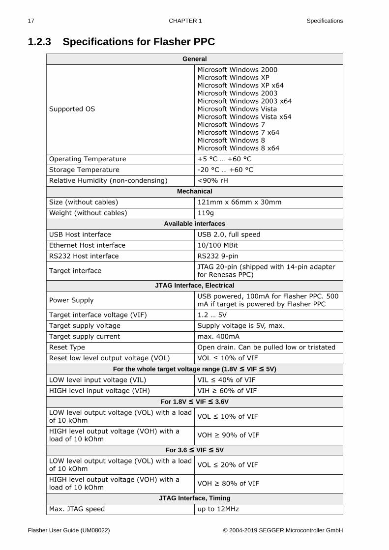
1.2.3 Specifications for Flasher PPC
General
Supported OS
Microsoft Windows 2000Microsoft Windows XPMicrosoft Windows XP x64Microsoft Windows 2003Microsoft Windows 2003 x64Microsoft Windows VistaMicrosoft Windows Vista x64Microsoft Windows 7Microsoft Windows 7 x64Microsoft Windows 8Microsoft Windows 8 x64
Operating Temperature +5 °C … +60 °CStorage Temperature -20 °C … +60 °CRelative Humidity (non-condensing) <90% rH
Mechanical
Size (without cables) 121mm x 66mm x 30mmWeight (without cables) 119g
Available interfaces
USB Host interface USB 2.0, full speedEthernet Host interface 10/100 MBitRS232 Host interface RS232 9-pin
Target interface JTAG 20-pin (shipped with 14-pin adapterfor Renesas PPC)
JTAG Interface, Electrical
Power Supply USB powered, 100mA for Flasher PPC. 500mA if target is powered by Flasher PPC
Target interface voltage (VIF) 1.2 … 5VTarget supply voltage Supply voltage is 5V, max.Target supply current max. 400mAReset Type Open drain. Can be pulled low or tristatedReset low level output voltage (VOL) VOL ≤ 10% of VIF
For the whole target voltage range (1.8V ≤ VIF ≤ 5V)
LOW level input voltage (VIL) VIL ≤ 40% of VIFHIGH level input voltage (VIH) VIH ≥ 60% of VIF
For 1.8V ≤ VIF ≤ 3.6V
LOW level output voltage (VOL) with a loadof 10 kOhm VOL ≤ 10% of VIF
HIGH level output voltage (VOH) with aload of 10 kOhm VOH ≥ 90% of VIF
For 3.6 ≤ VIF ≤ 5V
LOW level output voltage (VOL) with a loadof 10 kOhm VOL ≤ 20% of VIF
HIGH level output voltage (VOH) with aload of 10 kOhm VOH ≥ 80% of VIF
JTAG Interface, Timing
Max. JTAG speed up to 12MHz
Flasher User Guide (UM08022) © 2004-2019 SEGGER Microcontroller GmbH
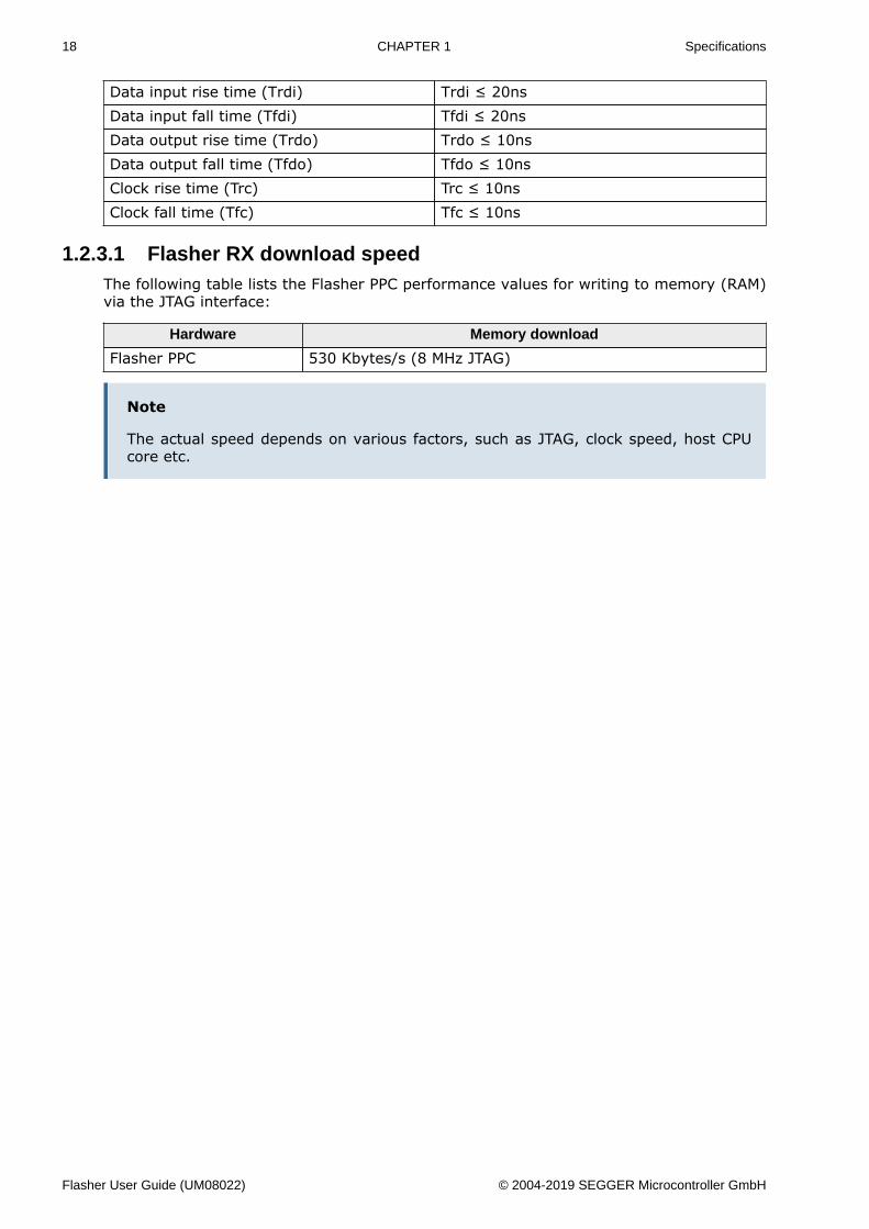
18 CHAPTER 1 Specifications
Data input rise time (Trdi) Trdi ≤ 20nsData input fall time (Tfdi) Tfdi ≤ 20nsData output rise time (Trdo) Trdo ≤ 10nsData output fall time (Tfdo) Tfdo ≤ 10nsClock rise time (Trc) Trc ≤ 10nsClock fall time (Tfc) Tfc ≤ 10ns
1.2.3.1 Flasher RX download speedThe following table lists the Flasher PPC performance values for writing to memory (RAM)via the JTAG interface:
Hardware Memory download
Flasher PPC 530 Kbytes/s (8 MHz JTAG)
Note
The actual speed depends on various factors, such as JTAG, clock speed, host CPUcore etc.
Flasher User Guide (UM08022) © 2004-2019 SEGGER Microcontroller GmbH
19 CHAPTER 1 Specifications
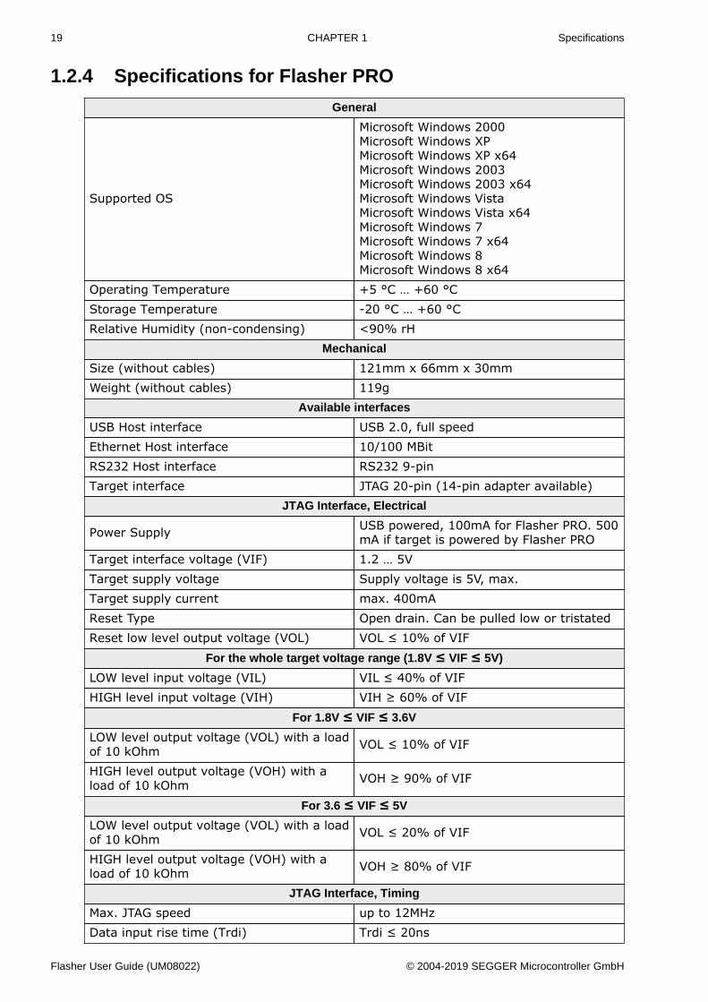
1.2.4 Specifications for Flasher PRO
General
Supported OS
Microsoft Windows 2000Microsoft Windows XPMicrosoft Windows XP x64Microsoft Windows 2003Microsoft Windows 2003 x64Microsoft Windows VistaMicrosoft Windows Vista x64Microsoft Windows 7Microsoft Windows 7 x64Microsoft Windows 8Microsoft Windows 8 x64
Operating Temperature +5 °C … +60 °CStorage Temperature -20 °C … +60 °CRelative Humidity (non-condensing) <90% rH
Mechanical
Size (without cables) 121mm x 66mm x 30mmWeight (without cables) 119g
Available interfaces
USB Host interface USB 2.0, full speedEthernet Host interface 10/100 MBitRS232 Host interface RS232 9-pinTarget interface JTAG 20-pin (14-pin adapter available)
JTAG Interface, Electrical
Power Supply USB powered, 100mA for Flasher PRO. 500mA if target is powered by Flasher PRO
Target interface voltage (VIF) 1.2 … 5VTarget supply voltage Supply voltage is 5V, max.Target supply current max. 400mAReset Type Open drain. Can be pulled low or tristatedReset low level output voltage (VOL) VOL ≤ 10% of VIF
For the whole target voltage range (1.8V ≤ VIF ≤ 5V)
LOW level input voltage (VIL) VIL ≤ 40% of VIFHIGH level input voltage (VIH) VIH ≥ 60% of VIF
For 1.8V ≤ VIF ≤ 3.6V
LOW level output voltage (VOL) with a loadof 10 kOhm VOL ≤ 10% of VIF
HIGH level output voltage (VOH) with aload of 10 kOhm VOH ≥ 90% of VIF
For 3.6 ≤ VIF ≤ 5V
LOW level output voltage (VOL) with a loadof 10 kOhm VOL ≤ 20% of VIF
HIGH level output voltage (VOH) with aload of 10 kOhm VOH ≥ 80% of VIF
JTAG Interface, Timing
Max. JTAG speed up to 12MHzData input rise time (Trdi) Trdi ≤ 20ns
Flasher User Guide (UM08022) © 2004-2019 SEGGER Microcontroller GmbH
20 CHAPTER 1 Specifications
Data input fall time (Tfdi) Tfdi ≤ 20nsData output rise time (Trdo) Trdo ≤ 10nsData output fall time (Tfdo) Tfdo ≤ 10nsClock rise time (Trc) Trc ≤ 10nsClock fall time (Tfc) Tfc ≤ 10ns
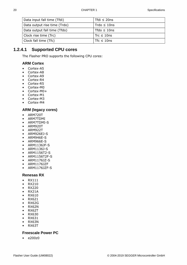
1.2.4.1 Supported CPU coresThe Flasher PRO supports the following CPU cores:
ARM Cortex• Cortex-A5• Cortex-A8• Cortex-A9• Cortex-R4• Cortex-R5• Cortex-M0• Cortex-M0+• Cortex-M1• Cortex-M3• Cortex-M4
ARM (legacy cores)• ARM720T• ARM7TDMI• ARM7TDMI-S• ARM920T• ARM922T• ARM926EJ-S• ARM946E-S• ARM966E-S• ARM1136JF-S• ARM1136J-S• ARM1156T2-S• ARM1156T2F-S• ARM1176JZ-S• ARM1176JZF• ARM1176JZF-S
Renesas RX• RX111• RX210• RX220• RX21A• RX610• RX621• RX62G• RX62N• RX62T• RX630• RX631• RX63N• RX63T
Freescale Power PC• e200z0
Flasher User Guide (UM08022) © 2004-2019 SEGGER Microcontroller GmbH
21 CHAPTER 1 Specifications
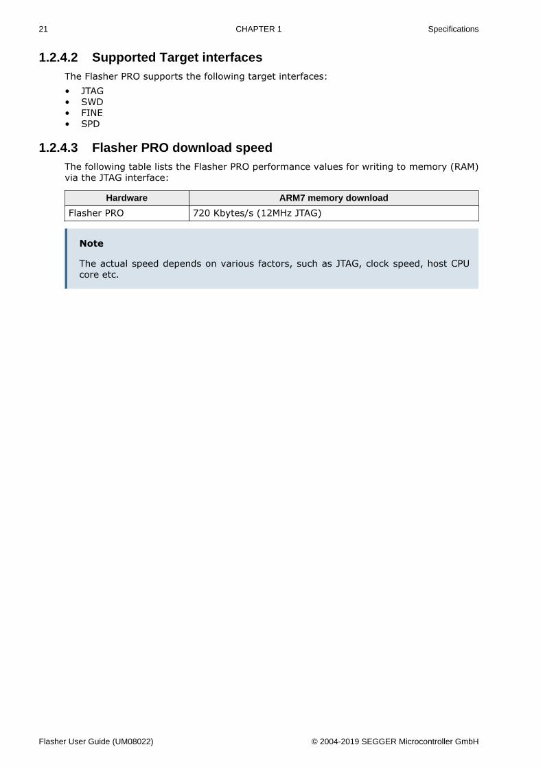
1.2.4.2 Supported Target interfacesThe Flasher PRO supports the following target interfaces:• JTAG• SWD• FINE• SPD
1.2.4.3 Flasher PRO download speedThe following table lists the Flasher PRO performance values for writing to memory (RAM)via the JTAG interface:
Hardware ARM7 memory download
Flasher PRO 720 Kbytes/s (12MHz JTAG)
Note
The actual speed depends on various factors, such as JTAG, clock speed, host CPUcore etc.
Flasher User Guide (UM08022) © 2004-2019 SEGGER Microcontroller GmbH
22 CHAPTER 1 Specifications
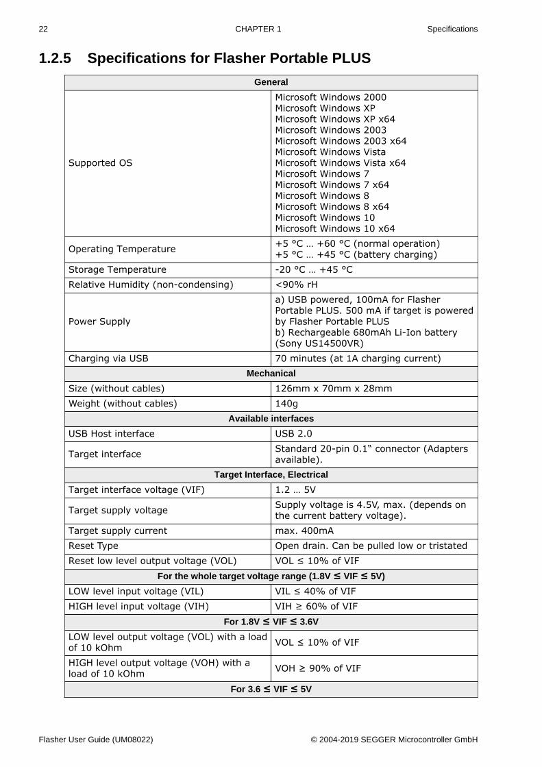
1.2.5 Specifications for Flasher Portable PLUS
General
Supported OS
Microsoft Windows 2000Microsoft Windows XPMicrosoft Windows XP x64Microsoft Windows 2003Microsoft Windows 2003 x64Microsoft Windows VistaMicrosoft Windows Vista x64Microsoft Windows 7Microsoft Windows 7 x64Microsoft Windows 8Microsoft Windows 8 x64Microsoft Windows 10Microsoft Windows 10 x64
Operating Temperature +5 °C … +60 °C (normal operation)+5 °C … +45 °C (battery charging)
Storage Temperature -20 °C … +45 °CRelative Humidity (non-condensing) <90% rH
Power Supply
a) USB powered, 100mA for FlasherPortable PLUS. 500 mA if target is poweredby Flasher Portable PLUSb) Rechargeable 680mAh Li-Ion battery(Sony US14500VR)
Charging via USB 70 minutes (at 1A charging current)Mechanical
Size (without cables) 126mm x 70mm x 28mmWeight (without cables) 140g
Available interfaces
USB Host interface USB 2.0
Target interface Standard 20-pin 0.1“ connector (Adaptersavailable).
Target Interface, Electrical
Target interface voltage (VIF) 1.2 … 5V
Target supply voltage Supply voltage is 4.5V, max. (depends onthe current battery voltage).
Target supply current max. 400mAReset Type Open drain. Can be pulled low or tristatedReset low level output voltage (VOL) VOL ≤ 10% of VIF
For the whole target voltage range (1.8V ≤ VIF ≤ 5V)
LOW level input voltage (VIL) VIL ≤ 40% of VIFHIGH level input voltage (VIH) VIH ≥ 60% of VIF
For 1.8V ≤ VIF ≤ 3.6V
LOW level output voltage (VOL) with a loadof 10 kOhm VOL ≤ 10% of VIF
HIGH level output voltage (VOH) with aload of 10 kOhm VOH ≥ 90% of VIF
For 3.6 ≤ VIF ≤ 5V
Flasher User Guide (UM08022) © 2004-2019 SEGGER Microcontroller GmbH
23 CHAPTER 1 Specifications
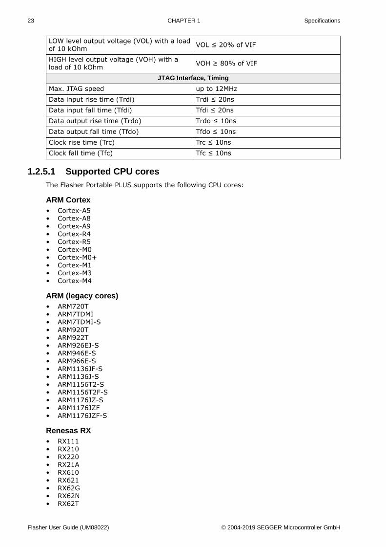
LOW level output voltage (VOL) with a loadof 10 kOhm VOL ≤ 20% of VIF
HIGH level output voltage (VOH) with aload of 10 kOhm VOH ≥ 80% of VIF
JTAG Interface, Timing
Max. JTAG speed up to 12MHzData input rise time (Trdi) Trdi ≤ 20nsData input fall time (Tfdi) Tfdi ≤ 20nsData output rise time (Trdo) Trdo ≤ 10nsData output fall time (Tfdo) Tfdo ≤ 10nsClock rise time (Trc) Trc ≤ 10nsClock fall time (Tfc) Tfc ≤ 10ns
1.2.5.1 Supported CPU coresThe Flasher Portable PLUS supports the following CPU cores:
ARM Cortex• Cortex-A5• Cortex-A8• Cortex-A9• Cortex-R4• Cortex-R5• Cortex-M0• Cortex-M0+• Cortex-M1• Cortex-M3• Cortex-M4
ARM (legacy cores)• ARM720T• ARM7TDMI• ARM7TDMI-S• ARM920T• ARM922T• ARM926EJ-S• ARM946E-S• ARM966E-S• ARM1136JF-S• ARM1136J-S• ARM1156T2-S• ARM1156T2F-S• ARM1176JZ-S• ARM1176JZF• ARM1176JZF-S
Renesas RX• RX111• RX210• RX220• RX21A• RX610• RX621• RX62G• RX62N• RX62T
Flasher User Guide (UM08022) © 2004-2019 SEGGER Microcontroller GmbH
24 CHAPTER 1 Specifications
• RX630• RX631• RX63N• RX63T
Freescale Power PC• e200z0
1.2.5.2 Supported Target interfacesThe Flasher Portable PLUS supports the following target interfaces:• JTAG• SWD• FINE• SPD
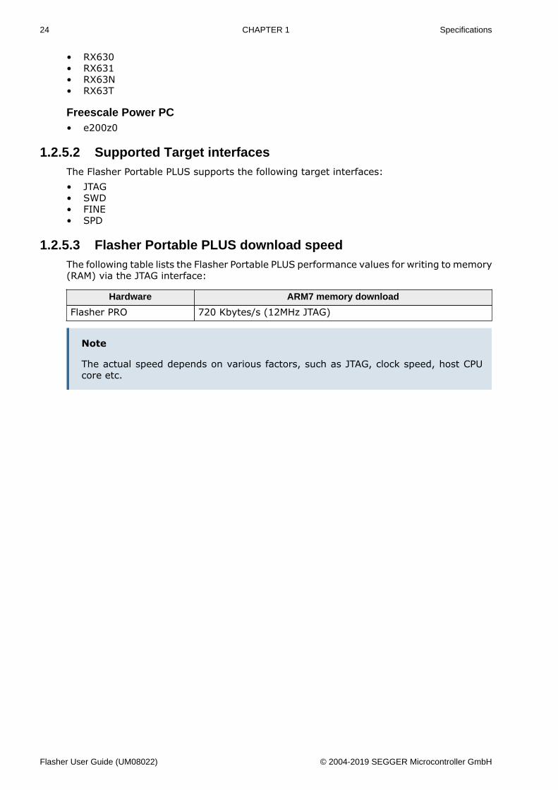
1.2.5.3 Flasher Portable PLUS download speedThe following table lists the Flasher Portable PLUS performance values for writing to memory(RAM) via the JTAG interface:
Hardware ARM7 memory download
Flasher PRO 720 Kbytes/s (12MHz JTAG)
Note
The actual speed depends on various factors, such as JTAG, clock speed, host CPUcore etc.
Flasher User Guide (UM08022) © 2004-2019 SEGGER Microcontroller GmbH
25 CHAPTER 1 Specifications
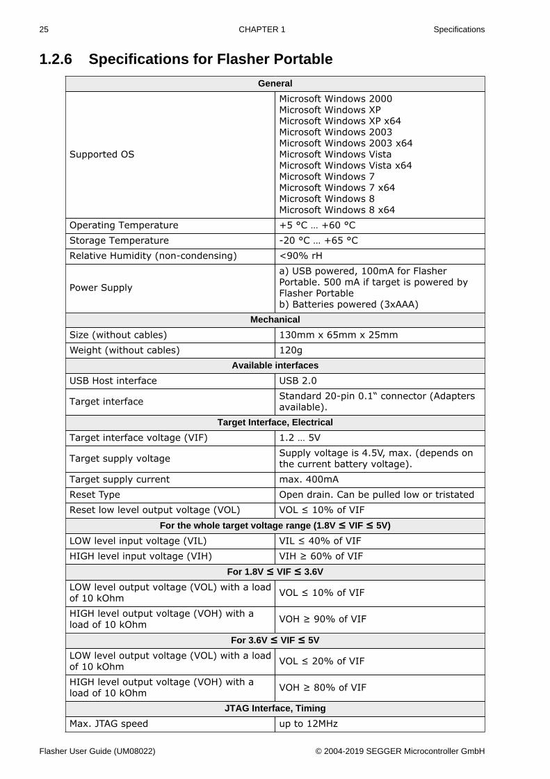
1.2.6 Specifications for Flasher Portable
General
Supported OS
Microsoft Windows 2000Microsoft Windows XPMicrosoft Windows XP x64Microsoft Windows 2003Microsoft Windows 2003 x64Microsoft Windows VistaMicrosoft Windows Vista x64Microsoft Windows 7Microsoft Windows 7 x64Microsoft Windows 8Microsoft Windows 8 x64
Operating Temperature +5 °C … +60 °CStorage Temperature -20 °C … +65 °CRelative Humidity (non-condensing) <90% rH
Power Supply
a) USB powered, 100mA for FlasherPortable. 500 mA if target is powered byFlasher Portableb) Batteries powered (3xAAA)
Mechanical
Size (without cables) 130mm x 65mm x 25mmWeight (without cables) 120g
Available interfaces
USB Host interface USB 2.0
Target interface Standard 20-pin 0.1“ connector (Adaptersavailable).
Target Interface, Electrical
Target interface voltage (VIF) 1.2 … 5V
Target supply voltage Supply voltage is 4.5V, max. (depends onthe current battery voltage).
Target supply current max. 400mAReset Type Open drain. Can be pulled low or tristatedReset low level output voltage (VOL) VOL ≤ 10% of VIF
For the whole target voltage range (1.8V ≤ VIF ≤ 5V)
LOW level input voltage (VIL) VIL ≤ 40% of VIFHIGH level input voltage (VIH) VIH ≥ 60% of VIF
For 1.8V ≤ VIF ≤ 3.6V
LOW level output voltage (VOL) with a loadof 10 kOhm VOL ≤ 10% of VIF
HIGH level output voltage (VOH) with aload of 10 kOhm VOH ≥ 90% of VIF
For 3.6V ≤ VIF ≤ 5V
LOW level output voltage (VOL) with a loadof 10 kOhm VOL ≤ 20% of VIF
HIGH level output voltage (VOH) with aload of 10 kOhm VOH ≥ 80% of VIF
JTAG Interface, Timing
Max. JTAG speed up to 12MHz
Flasher User Guide (UM08022) © 2004-2019 SEGGER Microcontroller GmbH
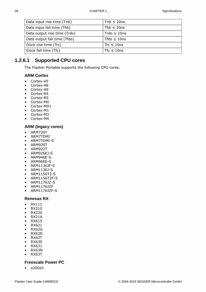
26 CHAPTER 1 Specifications
Data input rise time (Trdi) Trdi ≤ 20nsData input fall time (Tfdi) Tfdi ≤ 20nsData output rise time (Trdo) Trdo ≤ 10nsData output fall time (Tfdo) Tfdo ≤ 10nsClock rise time (Trc) Trc ≤ 10nsClock fall time (Tfc) Tfc ≤ 10ns
1.2.6.1 Supported CPU coresThe Flasher Portable supports the following CPU cores:
ARM Cortex• Cortex-A5• Cortex-A8• Cortex-A9• Cortex-R4• Cortex-R5• Cortex-M0• Cortex-M0+• Cortex-M1• Cortex-M3• Cortex-M4
ARM (legacy cores)• ARM720T• ARM7TDMI• ARM7TDMI-S• ARM920T• ARM922T• ARM926EJ-S• ARM946E-S• ARM966E-S• ARM1136JF-S• ARM1136J-S• ARM1156T2-S• ARM1156T2F-S• ARM1176JZ-S• ARM1176JZF• ARM1176JZF-S
Renesas RX• RX111• RX210• RX220• RX21A• RX610• RX621• RX62G• RX62N• RX62T• RX630• RX631• RX63N• RX63T
Freescale Power PC• e200z0
Flasher User Guide (UM08022) © 2004-2019 SEGGER Microcontroller GmbH

27 CHAPTER 1 Specifications
1.2.6.2 Supported Target interfacesThe Flasher Portable supports the following target interfaces:• JTAG• SWD• FINE• SPD
1.2.6.3 Flasher Portable download speedThe following table lists the Flasher Portable performance values for writing to memory(RAM) via the JTAG interface:
Hardware ARM7 memory download
Flasher PRO 720 Kbytes/s (12MHz JTAG)
Note
The actual speed depends on various factors, such as JTAG, clock speed, host CPUcore etc.
Flasher User Guide (UM08022) © 2004-2019 SEGGER Microcontroller GmbH
Chapter 2 Working with Flasher
This chapter describes functionality and how to use Flasher.
Flasher User Guide (UM08022) © 2004-2019 SEGGER Microcontroller GmbH
29 CHAPTER 2 Flasher Portable PLUS
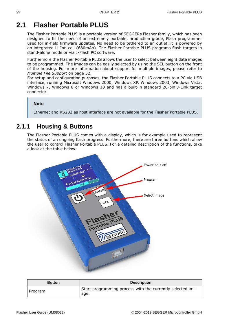
2.1 Flasher Portable PLUSThe Flasher Portable PLUS is a portable version of SEGGERs Flasher family, which has beendesigned to fill the need of an extremely portable, production grade, Flash programmerused for in-field firmware updates. No need to be tethered to an outlet, it is powered byan integrated Li-Ion cell (680mAh). The Flasher Portable PLUS programs flash targets instand-alone mode or via J-Flash PC software.
Furthermore the Flasher Portable PLUS allows the user to select between eight data imagesto be programmed. The images can be easily selected by using the SEL button on the frontof the housing. For more information about support for multiple images, please refer toMultiple File Support on page 52.For setup and configuration purposes, the Flasher Portable PLUS connects to a PC via USBinterface, running Microsoft Windows 2000, Windows XP, Windows 2003, Windows Vista,Windows 7, Windows 8 or Windows 10 and has a built-in standard 20-pin J-Link targetconnector.
Note
Ethernet and RS232 as host interface are not available for the Flasher Portable PLUS.
2.1.1 Housing & ButtonsThe Flasher Portable PLUS comes with a display, which is for example used to representthe status of an ongoing flash progress. Furthermore, there are three buttons which allowthe user to control Flasher Portable PLUS. For a detailed description of the functions, takea look at the table below:
Button Description
Program Start programming process with the currently selected im-age.
Flasher User Guide (UM08022) © 2004-2019 SEGGER Microcontroller GmbH
30 CHAPTER 2 Flasher Portable PLUS
Button Description
Select image Select the image to be programmed next time the Programbutton is pressed.
Power on/off
Used to power-on / power-off the Flasher Portable PLUS.Please note that to power up the Flasher Portable PLUS, thebutton should be hold for at least 1 second to make suresoftware can boot and take control of power circuit, so theFlasher Portable PLUS keeps powered, after releasing thebutton.
2.1.2 ConfigurationThe Flasher Portable PLUS has some configuration options the other Flashers do not have.
Option Description Value rangeDefaultvalue
AutoPowerOf-fOnIdle
Specifies the time interval after which theFlasher Portable will turn off without anyuser action
1 to 3600 60
ShowDatCR-CAfterProgram-ming
Activates displaying the data file CRC afterthe programming in the pop up message
0 = inactive, 1= active 0
If the Flasher.ini does not contain a [Config] section with the configuration option, thedefault value is used.
Example:
This sample will show the data file CRC after the programming and the auto power of isset to five minutes (=300 seconds).
[CONFIG]AutoPowerOffOnIdle = “300”ShowDatCRCAfterProgramming = “1”
Flasher User Guide (UM08022) © 2004-2019 SEGGER Microcontroller GmbH
31 CHAPTER 2 Flasher Portable
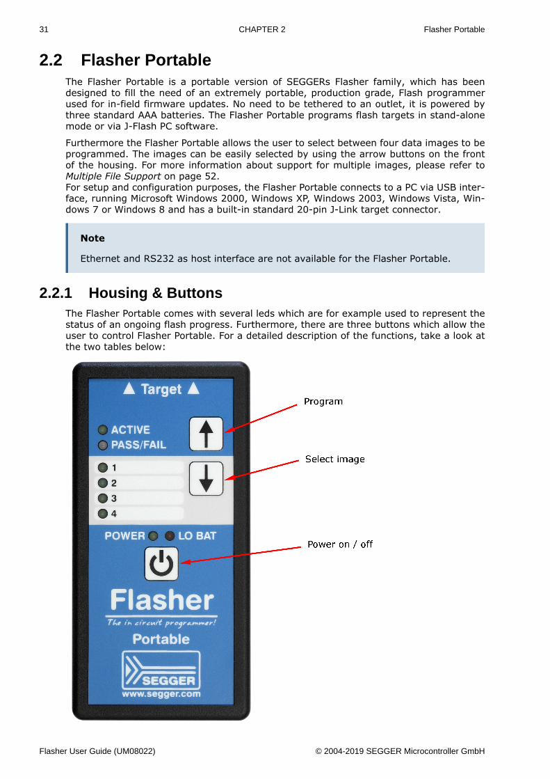
2.2 Flasher PortableThe Flasher Portable is a portable version of SEGGERs Flasher family, which has beendesigned to fill the need of an extremely portable, production grade, Flash programmerused for in-field firmware updates. No need to be tethered to an outlet, it is powered bythree standard AAA batteries. The Flasher Portable programs flash targets in stand-alonemode or via J-Flash PC software.
Furthermore the Flasher Portable allows the user to select between four data images to beprogrammed. The images can be easily selected by using the arrow buttons on the frontof the housing. For more information about support for multiple images, please refer toMultiple File Support on page 52.For setup and configuration purposes, the Flasher Portable connects to a PC via USB inter-face, running Microsoft Windows 2000, Windows XP, Windows 2003, Windows Vista, Win-dows 7 or Windows 8 and has a built-in standard 20-pin J-Link target connector.
Note
Ethernet and RS232 as host interface are not available for the Flasher Portable.
2.2.1 Housing & ButtonsThe Flasher Portable comes with several leds which are for example used to represent thestatus of an ongoing flash progress. Furthermore, there are three buttons which allow theuser to control Flasher Portable. For a detailed description of the functions, take a look atthe two tables below:
Flasher User Guide (UM08022) © 2004-2019 SEGGER Microcontroller GmbH
32 CHAPTER 2 Flasher Portable
LED Description
ACTIVE GREEN. Blinks while the Flasher Portable is busy / performsoperations on the target.
PASS/FAIL
GREEN/RED. Indicates, if the last flashing cycle was success-ful.• GREEN: Flashing cycle completed successfully.• RED: Flashing cycle completed with error.
1/2/3/4GREEN: Indicates which image is currently selected for pro-gramming. For more information about multiple image sup-port, please refer to Multiple File Support on page 52.
POWER GREEN: Indicates if Flasher is currently powered. Blinkswhile Flasher Portable tries to enumerate via USB.
LO BAT
1) The LED is off, meaning battery voltage is > 3.3V2) The red LED is constant on if battery voltage is low (≤3.3V). In this mode, Flasher still allows programming.3) The red LED starts blinking in case of the battery voltageis below 3.0V. Flasher refuse programming attempts.
Button Description
Program Start programming process with the currently selected im-age.
Select image Select the image to be programmed next time the Programbutton is pressed.
Power on/off
Used to power-on / power-off the Flasher Portable. Pleasenote that to power up the Flasher Portable, the buttonshould be hold for at least 1 second to make sure softwarecan boot and take control of power circuit, so the FlasherPortable keeps powered, after releasing the button
Flasher User Guide (UM08022) © 2004-2019 SEGGER Microcontroller GmbH
33 CHAPTER 2 File system
2.3 File systemThe Flasher supports 8.3 filenames only (8 characters filename, 3 characters file extension).Using longer filenames may result in incorrect operation. Integrated functions, like the FTPserver or the terminal server, will refuse writing files with long filenames.
Flasher User Guide (UM08022) © 2004-2019 SEGGER Microcontroller GmbH
34 CHAPTER 2 Setting up the IP interface
2.4 Setting up the IP interfaceSetting up the IP interface Some of the Flasher models come with an additional Ethernetinterface to communicate with the host system. These Flashers also come with a built-in webserver which allows some basic setup of the emulator, e.g. configuring a defaultgateway which allows using it even in large intranets. For more information, please referto TCP Services on page 75.
2.4.1 Connecting the first timeWhen connecting Flasher the first time, it attempts to acquire an IP address via DHCP. Therecommended way for finding out which IP address has been assigned to Flasher is, to usethe J-Link Configurator. The J-Link Configurator is a small GUI-based utility which showsa list of all emulator that are connected to the host PC via USB and Ethernet. For moreinformation about the J-Link Configurator, please refer to UM08001_JLink.pdf (J-Link / J-Trace user guide), chapter Setup, section J-Link Configurator. The setup of the IP interfaceof Flasher is the same as for other emulators of the J-Link family. For more informationabout how to setup the IP interface of Flasher, please refer to UM08001, J-Link / J-TraceUser Guide, chapter Setup, section Setting up the IP interface. For more information abouthow to use Flasher via Ethernet or prepare Flasher via Ethernet for stand-alone mode,please refer to Operating modes on page 35.
Flasher User Guide (UM08022) © 2004-2019 SEGGER Microcontroller GmbH
35 CHAPTER 2 Operating modes
2.5 Operating modesAll Flashers except the Flasher ATE are able to boot in 3 different modes:• J-Link mode• Stand-alone mode• MSD (Mass storage device) mode
Note
The Flasher ATE only supports the stand-alone mode.
Definition J-Link mode
Flasher is connected to a PC via USB/Ethernet and controlled by a PC application (J-Flash).If there is an RS232 connection to a PC, does not have any influence on if J-Link mode isentered or not. In this mode, Flasher can be used as a J-Link and controlled by the softwarein the J-Link software and documentation package (J-Link Commander, J-Flash, …)
Definition Stand-alone mode
This mode is entered when there is no active USB/Ethernet connection to a host PC, e.g.if Flasher is only powered via a USB power supply.
Definition MSD mode
Entered only if Flasher Start/Stop button (on Flasher Portable the “PROG” button) is keptpressed for at least 2 seconds while connection Flasher via USB. In this mode, Flasherenumerates as a mass storage device (like an USB Stick) at the host PC. In this mode,configuration + data files can be manually placed on the Flasher and the flasher logfilecan be read out.
2.5.1 J-Link modeIf you want to use Flasher for the first time you need to install the J-Link software and doc-umentation package. After installation, connect Flasher to the host PC via USB or Ethernet.For more information about how to install the J-Link software and documentation packageplease refer to the J-Link / J-Trace User Guide, chapter Setup which can be downloadedfrom https://www.segger.com/jlink-software.html.
2.5.1.1 Connecting the target system
Power-on sequence
In general, Flasher should be powered on before connecting it with the target device. Thatmeans you should first connect Flasher with the host system via USB / Ethernet and thenconnect Flasher with the target device via JTAG or SWD. Power-on the device after youconnected Flasher to it. Flasher will boot in “J-Link mode”.
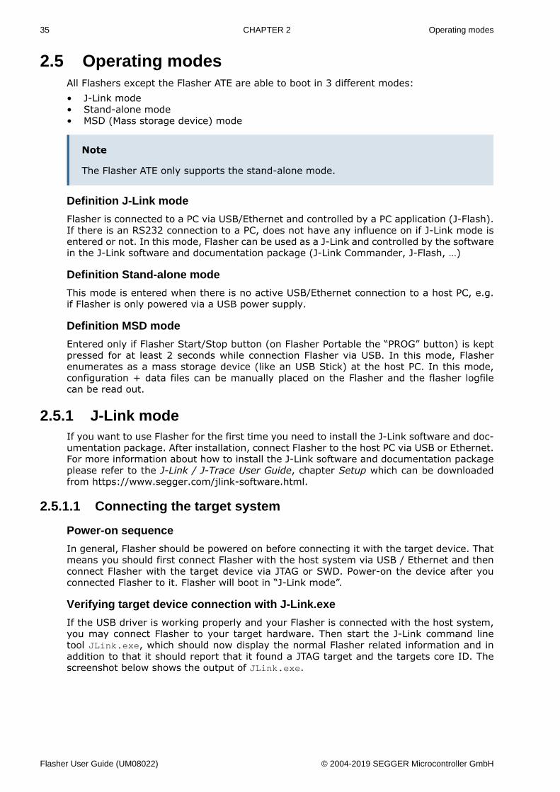
Verifying target device connection with J-Link.exe
If the USB driver is working properly and your Flasher is connected with the host system,you may connect Flasher to your target hardware. Then start the J-Link command linetool JLink.exe, which should now display the normal Flasher related information and inaddition to that it should report that it found a JTAG target and the targets core ID. Thescreenshot below shows the output of JLink.exe.
Flasher User Guide (UM08022) © 2004-2019 SEGGER Microcontroller GmbH
36 CHAPTER 2 Operating modes
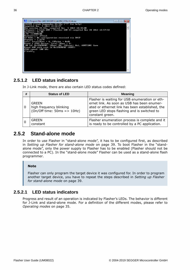
2.5.1.2 LED status indicatorsIn J-Link mode, there are also certain LED status codes defined:
# Status of LED Meaning
0GREENhigh frequency blinking(On/Off time: 50ms => 10Hz)
Flasher is waiting for USB enumeration or eth-ernet link. As soon as USB has been enumer-ated or ethernet link has been established, thegreen LED stops flashing and is switched toconstant green.
0 GREENconstant
Flasher enumeration process is complete and itis ready to be controlled by a PC application.
2.5.2 Stand-alone modeIn order to use Flasher in “stand-alone mode”, it has to be configured first, as describedin Setting up Flasher for stand-alone mode on page 39. To boot Flasher in the “stand-alone mode”, only the power supply to Flasher has to be enabled (Flasher should not beconnected to a PC). In the “stand-alone mode” Flasher can be used as a stand-alone flashprogrammer.
Note
Flasher can only program the target device it was configured for. In order to programanother target device, you have to repeat the steps described in Setting up Flasherfor stand-alone mode on page 39.
2.5.2.1 LED status indicatorsProgress and result of an operation is indicated by Flasher’s LEDs. The behavior is differentfor J-Link and stand-alone mode. For a definition of the different modes, please refer toOperating modes on page 35.
Flasher User Guide (UM08022) © 2004-2019 SEGGER Microcontroller GmbH
37 CHAPTER 2 Operating modes
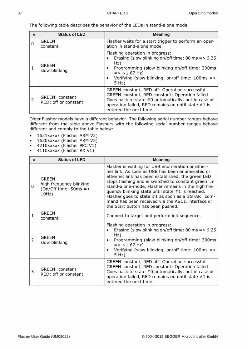
The following table describes the behavior of the LEDs in stand-alone mode.
# Status of LED Meaning
0 GREENconstant
Flasher waits for a start trigger to perform an oper-ation in stand-alone mode.
1 GREENslow blinking
Flashing operation in progress:• Erasing (slow blinking on/off time: 80 ms => 6.25
Hz)• Programming (slow blinking on/off time: 300ms
=> ~1.67 Hz)• Verifying (slow blinking, on/off time: 100ms =>
5 Hz)
2 GREEN: constantRED: off or constant
GREEN constant, RED off: Operation successful.GREEN constant, RED constant: Operation failedGoes back to state #0 automatically, but in case ofoperation failed, RED remains on until state #1 isentered the next time.
Older Flasher models have a different behavior. The following serial number ranges behavedifferent from the table above Flashers with the following serial number ranges behavedifferent and comply to the table below:• 1621xxxxx (Flasher ARM V2)• 1630xxxxx (Flasher ARM V3)• 4210xxxxx (Flasher PPC V1)• 4110xxxxx (Flasher RX V1)
# Status of LED Meaning
0
GREENhigh frequency blinking(On/Off time: 50ms =>10Hz)
Flasher is waiting for USB enumeration or ether-net link. As soon as USB has been enumerated orethernet link has been established, the green LEDstops flashing and is switched to constant green. Instand-alone-mode, Flasher remains in the high fre-quency blinking state until state #1 is reached.Flasher goes to state #1 as soon as a #START com-mand has been received via the ASCII interface orthe Start button has been pushed.
1 GREENconstant Connect to target and perform init sequence.
2 GREENslow blinking
Flashing operation in progress:• Erasing (slow blinking on/off time: 80 ms => 6.25
Hz)• Programming (slow blinking on/off time: 300ms
=> ~1.67 Hz)• Verifying (slow blinking, on/off time: 100ms =>
5 Hz)
3 GREEN: constantRED: off or constant
GREEN constant, RED off: Operation successful.GREEN constant, RED constant: Operation failedGoes back to state #0 automatically, but in case ofoperation failed, RED remains on until state #1 isentered the next time.
Flasher User Guide (UM08022) © 2004-2019 SEGGER Microcontroller GmbH
38 CHAPTER 2 Operating modes
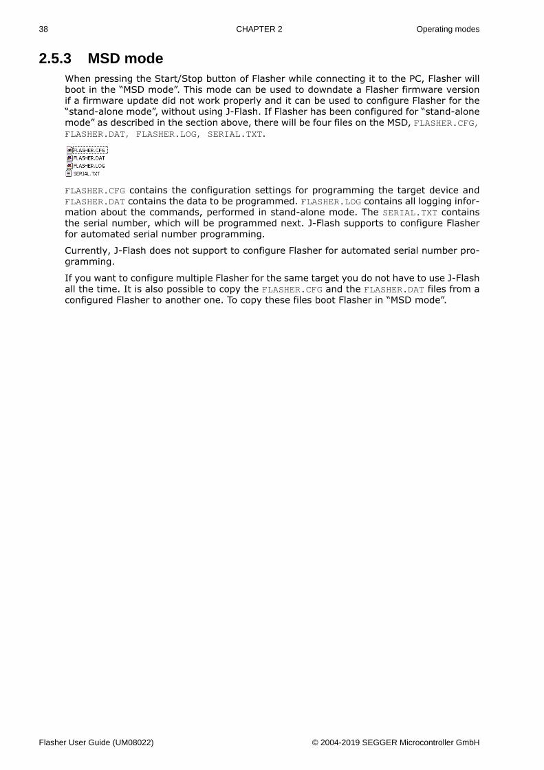
2.5.3 MSD modeWhen pressing the Start/Stop button of Flasher while connecting it to the PC, Flasher willboot in the “MSD mode”. This mode can be used to downdate a Flasher firmware versionif a firmware update did not work properly and it can be used to configure Flasher for the“stand-alone mode”, without using J-Flash. If Flasher has been configured for “stand-alonemode” as described in the section above, there will be four files on the MSD, FLASHER.CFG,FLASHER.DAT, FLASHER.LOG, SERIAL.TXT.
FLASHER.CFG contains the configuration settings for programming the target device andFLASHER.DAT contains the data to be programmed. FLASHER.LOG contains all logging infor-mation about the commands, performed in stand-alone mode. The SERIAL.TXT containsthe serial number, which will be programmed next. J-Flash supports to configure Flasherfor automated serial number programming.
Currently, J-Flash does not support to configure Flasher for automated serial number pro-gramming.
If you want to configure multiple Flasher for the same target you do not have to use J-Flashall the time. It is also possible to copy the FLASHER.CFG and the FLASHER.DAT files from aconfigured Flasher to another one. To copy these files boot Flasher in “MSD mode”.
Flasher User Guide (UM08022) © 2004-2019 SEGGER Microcontroller GmbH
39 CHAPTER 2 Setting up Flasher for stand-alone mode
2.6 Setting up Flasher for stand-alone modeIn order to set up Flasher for the stand-alone mode it needs to be configured once using theJ-Flash software. For more information about J-Flash, please refer to the J-Flash User Guide.
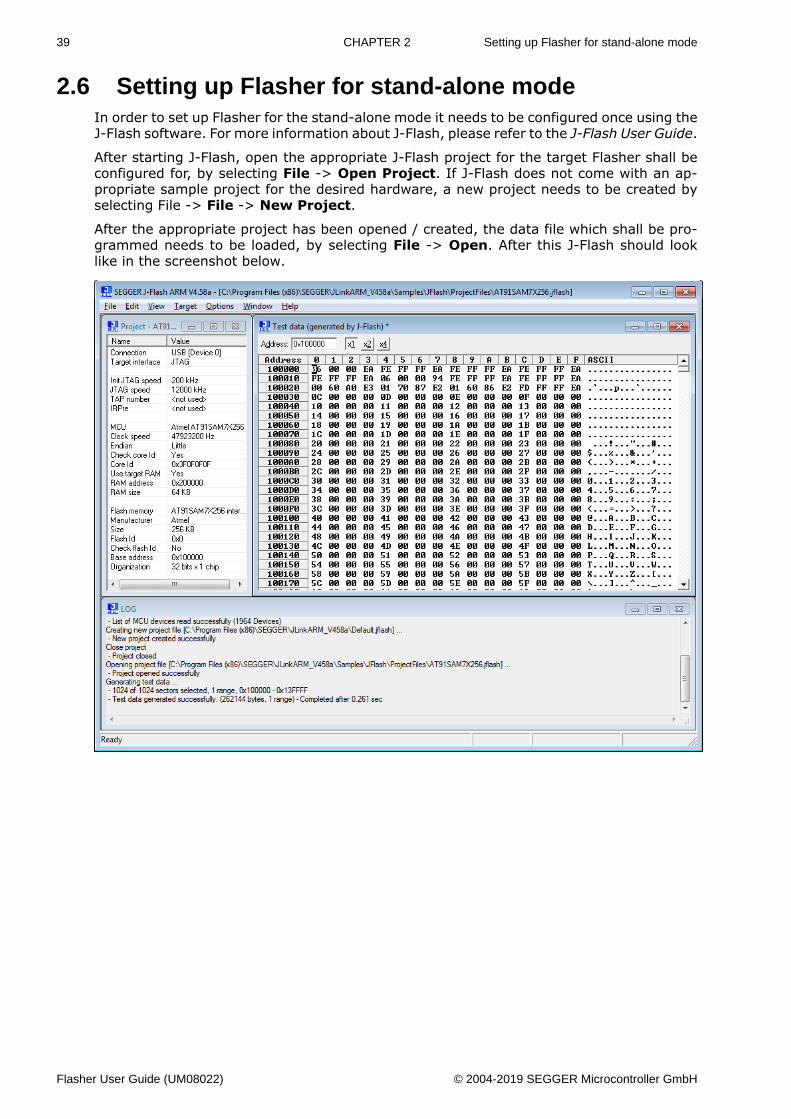
After starting J-Flash, open the appropriate J-Flash project for the target Flasher shall beconfigured for, by selecting File -> Open Project. If J-Flash does not come with an ap-propriate sample project for the desired hardware, a new project needs to be created byselecting File -> File -> New Project.
After the appropriate project has been opened / created, the data file which shall be pro-grammed needs to be loaded, by selecting File -> Open. After this J-Flash should looklike in the screenshot below.
Flasher User Guide (UM08022) © 2004-2019 SEGGER Microcontroller GmbH
40 CHAPTER 2 Setting up Flasher for stand-alone mode
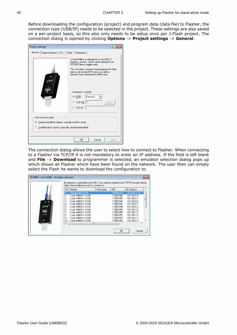
Before downloading the configuration (project) and program data (data file) to Flasher, theconnection type (USB/IP) needs to be selected in the project. These settings are also savedon a per-project basis, so this also only needs to be setup once per J-Flash project. Theconnection dialog is opened by clicking Options -> Project settings -> General.
The connection dialog allows the user to select how to connect to Flasher. When connectingto a Flasher via TCP/IP it is not mandatory to enter an IP address. If the field is left blankand File -> Download to programmer is selected, an emulator selection dialog pops upwhich shows all Flasher which have been found on the network. The user then can simplyselect the Flash he wants to download the configuration to.
Flasher User Guide (UM08022) © 2004-2019 SEGGER Microcontroller GmbH
41 CHAPTER 2 Setting up Flasher for stand-alone mode
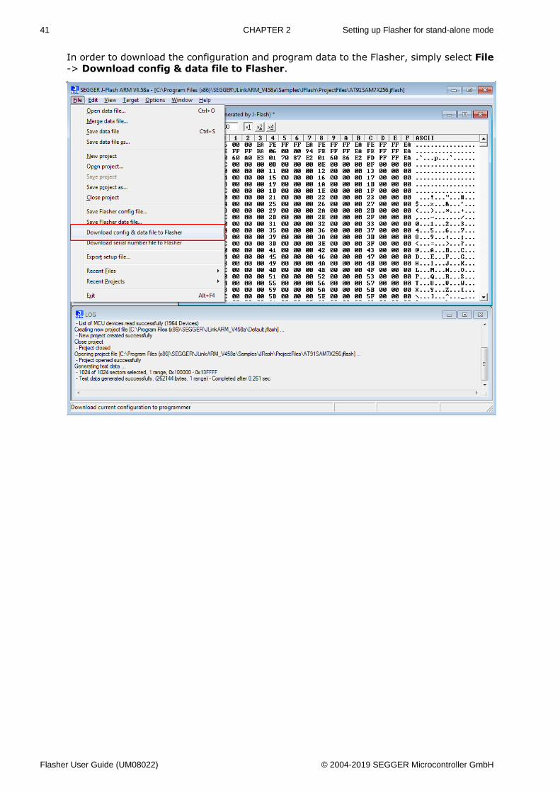
In order to download the configuration and program data to the Flasher, simply select File-> Download config & data file to Flasher.
Flasher User Guide (UM08022) © 2004-2019 SEGGER Microcontroller GmbH
42 CHAPTER 2 Setting up Flasher for stand-alone mode
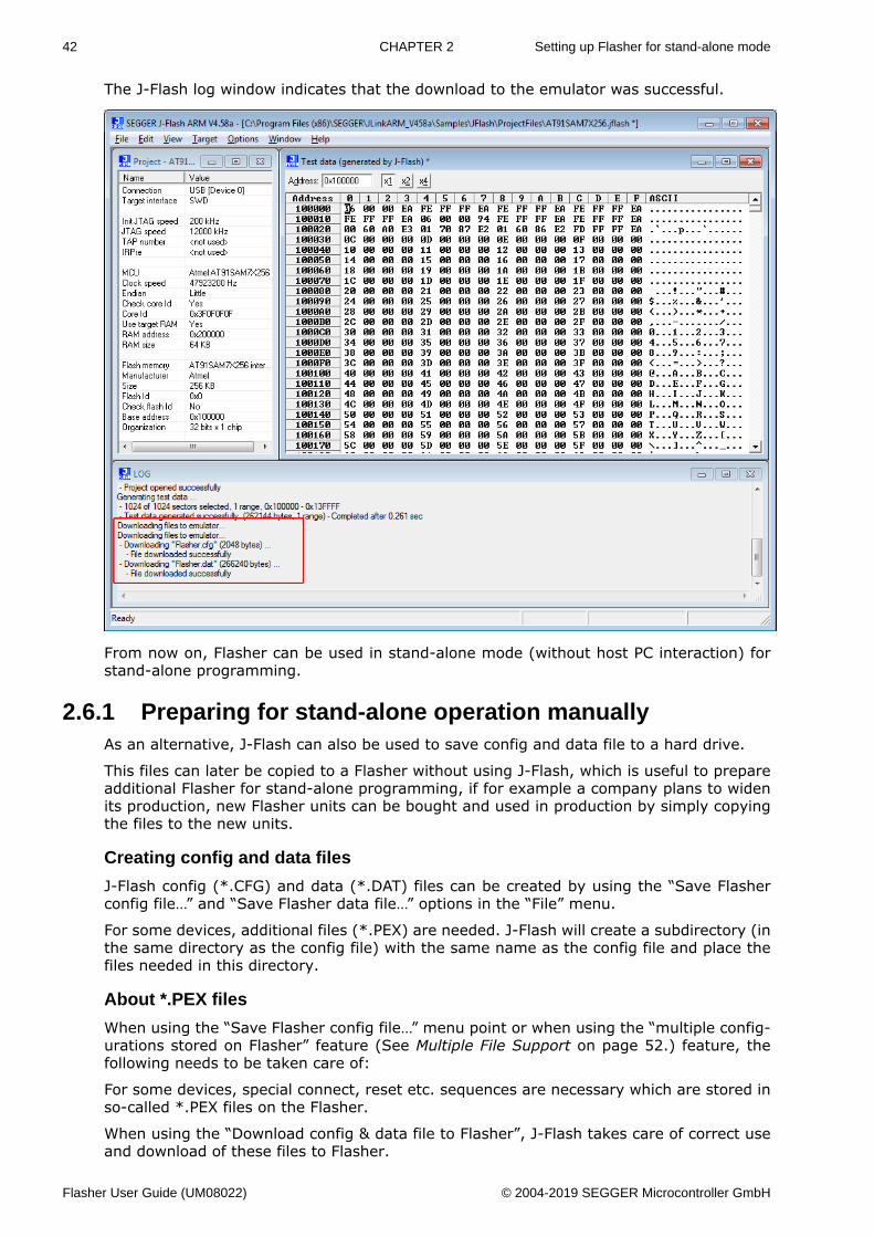
The J-Flash log window indicates that the download to the emulator was successful.
From now on, Flasher can be used in stand-alone mode (without host PC interaction) forstand-alone programming.
2.6.1 Preparing for stand-alone operation manuallyAs an alternative, J-Flash can also be used to save config and data file to a hard drive.
This files can later be copied to a Flasher without using J-Flash, which is useful to prepareadditional Flasher for stand-alone programming, if for example a company plans to widenits production, new Flasher units can be bought and used in production by simply copyingthe files to the new units.
Creating config and data files
J-Flash config (*.CFG) and data (*.DAT) files can be created by using the “Save Flasherconfig file…” and “Save Flasher data file…” options in the “File” menu.
For some devices, additional files (*.PEX) are needed. J-Flash will create a subdirectory (inthe same directory as the config file) with the same name as the config file and place thefiles needed in this directory.
About *.PEX files
When using the “Save Flasher config file…” menu point or when using the “multiple config-urations stored on Flasher” feature (See Multiple File Support on page 52.) feature, thefollowing needs to be taken care of:
For some devices, special connect, reset etc. sequences are necessary which are stored inso-called *.PEX files on the Flasher.
When using the “Download config & data file to Flasher”, J-Flash takes care of correct useand download of these files to Flasher.
Flasher User Guide (UM08022) © 2004-2019 SEGGER Microcontroller GmbH
43 CHAPTER 2 Setting up Flasher for stand-alone mode
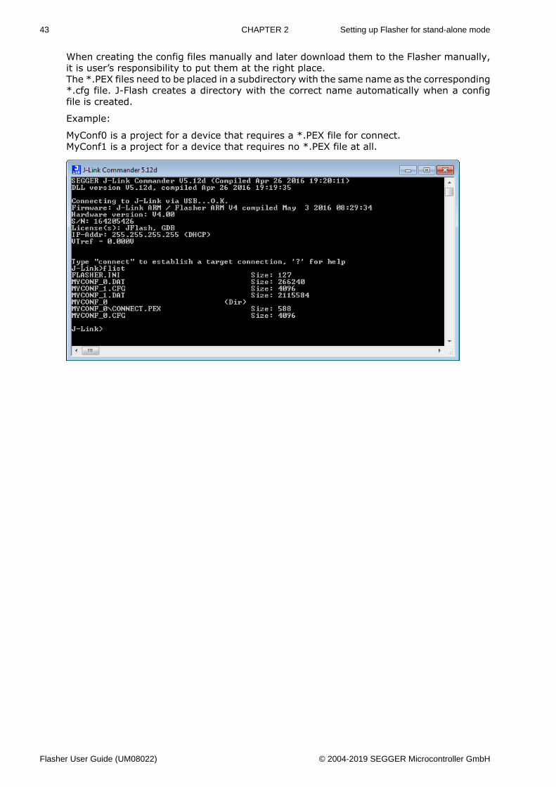
When creating the config files manually and later download them to the Flasher manually,it is user’s responsibility to put them at the right place.The *.PEX files need to be placed in a subdirectory with the same name as the corresponding*.cfg file. J-Flash creates a directory with the correct name automatically when a configfile is created.
Example:
MyConf0 is a project for a device that requires a *.PEX file for connect.MyConf1 is a project for a device that requires no *.PEX file at all.
Flasher User Guide (UM08022) © 2004-2019 SEGGER Microcontroller GmbH
44 CHAPTER 2 Universal Flash Loader mode
2.7 Universal Flash Loader modeAs an alternative to the stand-alone mode, configured via J-Flash, there is the UniversalFlash Loader mode. While the normal stand-alone mode relies on using the debug interfaceof the device, the Universal Flash Loader mode uses device or vendor specific programminginterfaces and protocols and therefore it is independent of the CPU core.
The Universal Flash Loader is available for the Flasher PRO and for the Flasher Portable.For some of the supported devices, SEGGER offers specific adapters.
2.7.1 Preparing manuallyThe Universal Flash Loader uses an initialization file (*.UNI), a device specific flash pro-gramming algorithm (*.PEX) and a data file (*.HEX, *.MOT, *.BIN or *.DAT).
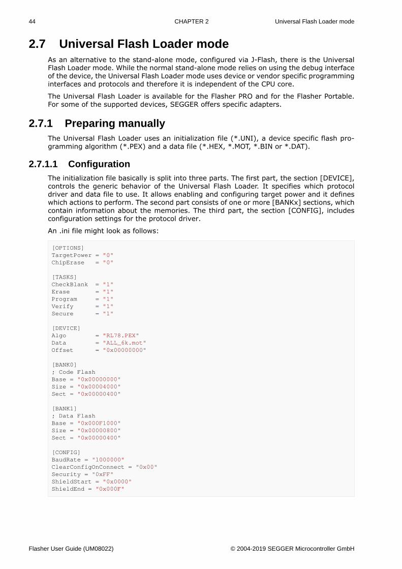
2.7.1.1 ConfigurationThe initialization file basically is split into three parts. The first part, the section [DEVICE],controls the generic behavior of the Universal Flash Loader. It specifies which protocoldriver and data file to use. It allows enabling and configuring target power and it defineswhich actions to perform. The second part consists of one or more [BANKx] sections, whichcontain information about the memories. The third part, the section [CONFIG], includesconfiguration settings for the protocol driver.
An .ini file might look as follows:
[OPTIONS]TargetPower = "0"ChipErase = "0"
[TASKS]CheckBlank = "1"Erase = "1"Program = "1"Verify = "1"Secure = "1"
[DEVICE]Algo = "RL78.PEX"Data = "ALL_6k.mot"Offset = "0x00000000"
[BANK0]; Code FlashBase = "0x00000000"Size = "0x00004000"Sect = "0x00000400"
[BANK1]; Data FlashBase = "0x000F1000"Size = "0x00000800"Sect = "0x00000400"
[CONFIG]BaudRate = "1000000"ClearConfigOnConnect = "0x00"Security = "0xFF"ShieldStart = "0x0000"ShieldEnd = "0x000F"
Flasher User Guide (UM08022) © 2004-2019 SEGGER Microcontroller GmbH
45 CHAPTER 2 Universal Flash Loader mode
[OPTIONS]
TargetPower
If set to a value >0, power is applied to the target. The value defines the delay (in ms)after enabling the target power supply and before starting to communicate with the target.
ChipErase
If set to 1, the chip erase function is called for erasing the chip.
Note
Do not enable this setting if the flash programming algorithm does not support chiperase.
[TASKS]
CheckBlank
Defines if a blank check should be performed before erasing a sector.
Erase
Defines if the sector should be erased before programming.
Program
Defines if the sector should be programmed.
Verify
Defines if the sector should be verified after programming.
Secure
Defines if the device should be secured or protected against read-out after verifying.
[DEVICE]
Algo
File name of the flash programming algorithm. This file is provided by SEGGER and willtypically support a series of devices.
Data
File name of the data file to program. The flasher supports the Flasher DTA, the Intel HEX,the Motorola S-Record and the binary file format. Flasher DAT files are generated by J-Flashand offer high performance together with high flexibility. The other file formats produce asmall overhead, because they have to be parsed before the data can be programmed.
Offset
Offset to apply when programming a binary data file. Unless specified differently, binaryfiles start at offset 0x00000000.
[BANKx]
x blocks with configuration data for the flash banks. All three parameters (Base, Size andSect) are mandatory.
Base
Base address of the flash bank.
Flasher User Guide (UM08022) © 2004-2019 SEGGER Microcontroller GmbH
46 CHAPTER 2 Universal Flash Loader mode
Size
Total size of the flash bank.
Sect
Sector size of the flash bank.
[CONFIG]
This section includes specific configuration data for the flash programming algorithm.There are no general parameters.
Note
The data file must be organized in ascending address order. Gaps can be included. Butdescending addresses will result in programming errors. You can sort the data files byloading them into the J-Flash tool and saving it as a new file.
Flasher User Guide (UM08022) © 2004-2019 SEGGER Microcontroller GmbH
47 CHAPTER 2 Universal Flash Loader mode
2.7.1.2 Configuration Data for Renesas RL78/G10The RL78/G10 devices do not require any configuration data.
2.7.1.3 Configuration Data for Renesas RL78 (except RL78/G10)
BaudRate
The baud rate used for programming. Possible values are 115,200, 250,000, 500,000 and1,000,000.
ClearConfigOnConnect
If this is set to 1, the first sector holding the configuration is cleared on connect. This willespecially reset the clock configuration to its default value allowing a higher programmingspeed.
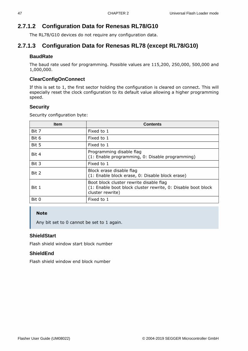
Security
Security configuration byte:
Item Contents
Bit 7 Fixed to 1Bit 6 Fixed to 1Bit 5 Fixed to 1
Bit 4 Programming disable flag(1: Enable programming, 0: Disable programming)
Bit 3 Fixed to 1
Bit 2 Block erase disable flag(1: Enable block erase, 0: Disable block erase)
Bit 1Boot block cluster rewrite disable flag(1: Enable boot block cluster rewrite, 0: Disable boot blockcluster rewrite)
Bit 0 Fixed to 1
Note
Any bit set to 0 cannot be set to 1 again.
ShieldStart
Flash shield window start block number
ShieldEnd
Flash shield window end block number
Flasher User Guide (UM08022) © 2004-2019 SEGGER Microcontroller GmbH
48 CHAPTER 2 Universal Flash Loader mode
2.7.1.4 Configuration Data for ST STM8
HighSpeed
The interface mode (0 = low speed / 1 = high speed) used for communication.
ROP
Read out protection configuration byte: Depending on the target, 0x00 or 0xAA.
SectorSize
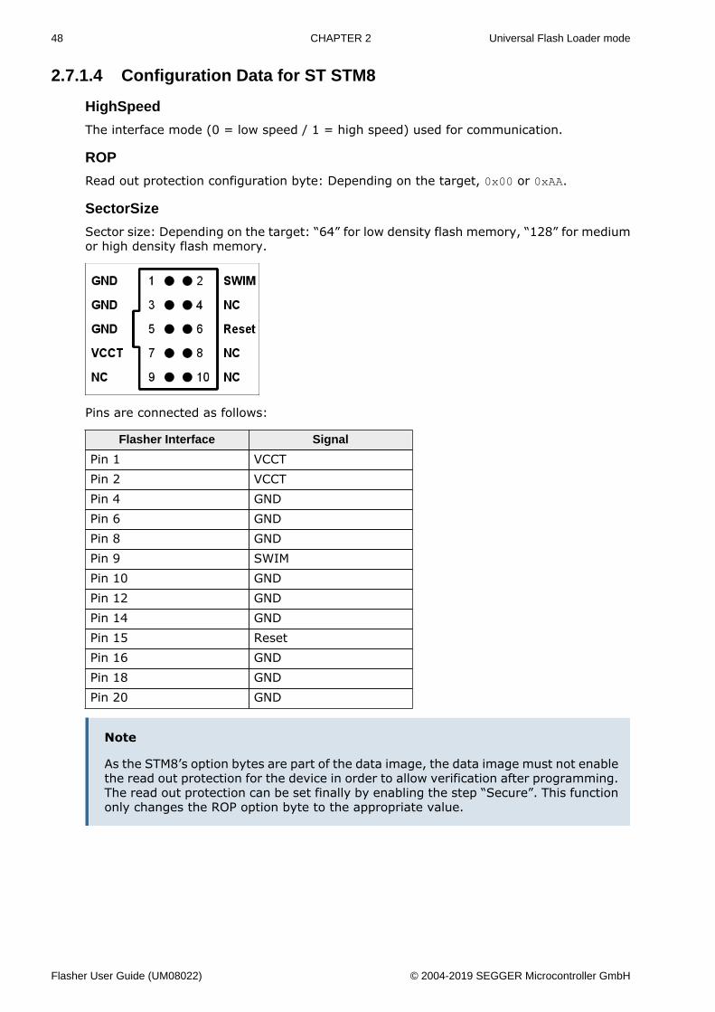
Sector size: Depending on the target: “64” for low density flash memory, “128” for mediumor high density flash memory.
Pins are connected as follows:
Flasher Interface Signal
Pin 1 VCCTPin 2 VCCTPin 4 GNDPin 6 GNDPin 8 GNDPin 9 SWIMPin 10 GNDPin 12 GNDPin 14 GNDPin 15 ResetPin 16 GNDPin 18 GNDPin 20 GND
Note
As the STM8’s option bytes are part of the data image, the data image must not enablethe read out protection for the device in order to allow verification after programming.The read out protection can be set finally by enabling the step “Secure”. This functiononly changes the ROP option byte to the appropriate value.
Flasher User Guide (UM08022) © 2004-2019 SEGGER Microcontroller GmbH
49 CHAPTER 2 Universal Flash Loader mode
2.7.1.5 Configuration Data for TI MSP430: 1xx, 2xx and 4xx series
JTAGSpeed
The JTAG interface speed used for communication.
ClocksMassErase
Number of clocks required for a mass erase. This value depends on the device, please referto the data sheet.
ClocksSegmentErase
Number of clocks required for a segment erase. This value depends on the device, pleaserefer to the data sheet.
ClocksProgram
Number of clocks required for a word programming operation. This value depends on thedevice, please refer to the data sheet.
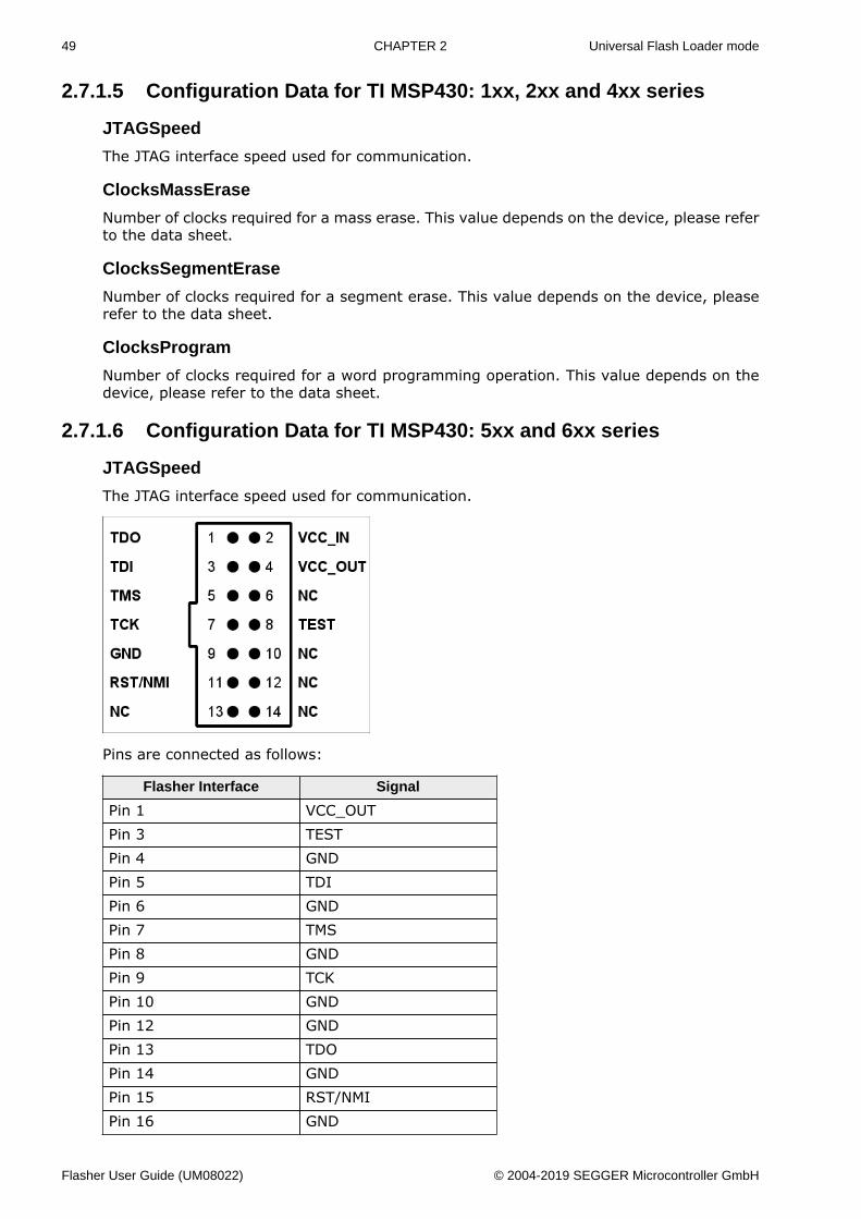
2.7.1.6 Configuration Data for TI MSP430: 5xx and 6xx series
JTAGSpeed
The JTAG interface speed used for communication.
Pins are connected as follows:
Flasher Interface Signal
Pin 1 VCC_OUTPin 3 TESTPin 4 GNDPin 5 TDIPin 6 GNDPin 7 TMSPin 8 GNDPin 9 TCKPin 10 GNDPin 12 GNDPin 13 TDOPin 14 GNDPin 15 RST/NMIPin 16 GND
Flasher User Guide (UM08022) © 2004-2019 SEGGER Microcontroller GmbH
50 CHAPTER 2 Universal Flash Loader mode
Flasher Interface Signal
Pin 18 GNDPin 20 GND
Flasher User Guide (UM08022) © 2004-2019 SEGGER Microcontroller GmbH

51 CHAPTER 2 Universal Flash Loader mode
2.7.2 Preparing using the PC utilityIn order to set up Flasher for the Universal Flash Loader mode, a PC utility called SEGGERUniversal Flash Loader Configurator is available for download.
The Universal Flash Loader Configurator comes with a large list of devices and flash pro-gramming algorithms. If you are going to use a device from one of the supported familieswhich currently is not available in the utility, feel free to contact the support.
Flasher User Guide (UM08022) © 2004-2019 SEGGER Microcontroller GmbH
52 CHAPTER 2 Multiple File Support
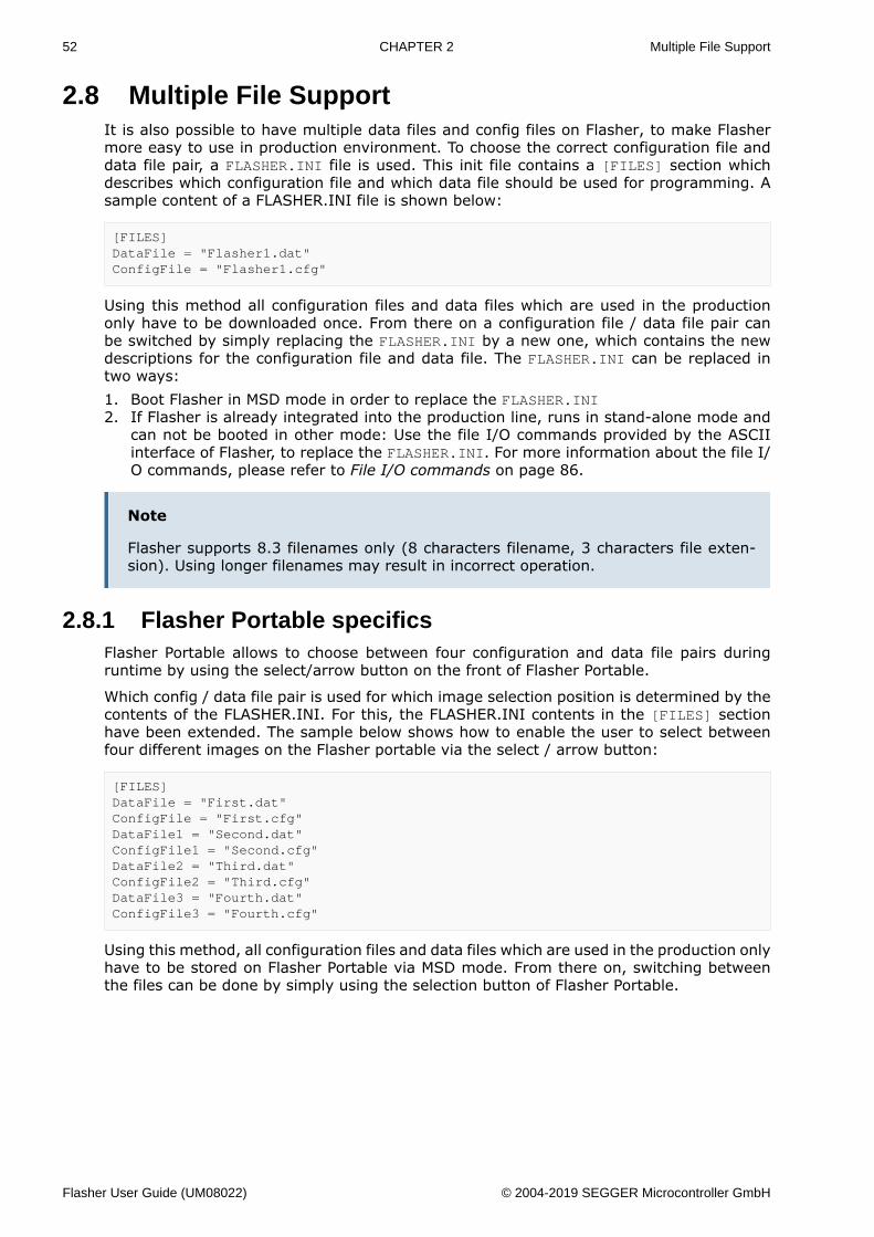
2.8 Multiple File SupportIt is also possible to have multiple data files and config files on Flasher, to make Flashermore easy to use in production environment. To choose the correct configuration file anddata file pair, a FLASHER.INI file is used. This init file contains a [FILES] section whichdescribes which configuration file and which data file should be used for programming. Asample content of a FLASHER.INI file is shown below:
[FILES]DataFile = "Flasher1.dat"ConfigFile = "Flasher1.cfg"
Using this method all configuration files and data files which are used in the productiononly have to be downloaded once. From there on a configuration file / data file pair canbe switched by simply replacing the FLASHER.INI by a new one, which contains the newdescriptions for the configuration file and data file. The FLASHER.INI can be replaced intwo ways:1. Boot Flasher in MSD mode in order to replace the FLASHER.INI2. If Flasher is already integrated into the production line, runs in stand-alone mode and
can not be booted in other mode: Use the file I/O commands provided by the ASCIIinterface of Flasher, to replace the FLASHER.INI. For more information about the file I/O commands, please refer to File I/O commands on page 86.
Note
Flasher supports 8.3 filenames only (8 characters filename, 3 characters file exten-sion). Using longer filenames may result in incorrect operation.
2.8.1 Flasher Portable specificsFlasher Portable allows to choose between four configuration and data file pairs duringruntime by using the select/arrow button on the front of Flasher Portable.
Which config / data file pair is used for which image selection position is determined by thecontents of the FLASHER.INI. For this, the FLASHER.INI contents in the [FILES] sectionhave been extended. The sample below shows how to enable the user to select betweenfour different images on the Flasher portable via the select / arrow button:
[FILES]DataFile = "First.dat"ConfigFile = "First.cfg"DataFile1 = "Second.dat"ConfigFile1 = "Second.cfg"DataFile2 = "Third.dat"ConfigFile2 = "Third.cfg"DataFile3 = "Fourth.dat"ConfigFile3 = "Fourth.cfg"
Using this method, all configuration files and data files which are used in the production onlyhave to be stored on Flasher Portable via MSD mode. From there on, switching betweenthe files can be done by simply using the selection button of Flasher Portable.
Flasher User Guide (UM08022) © 2004-2019 SEGGER Microcontroller GmbH
53 CHAPTER 2 Multiple File Support
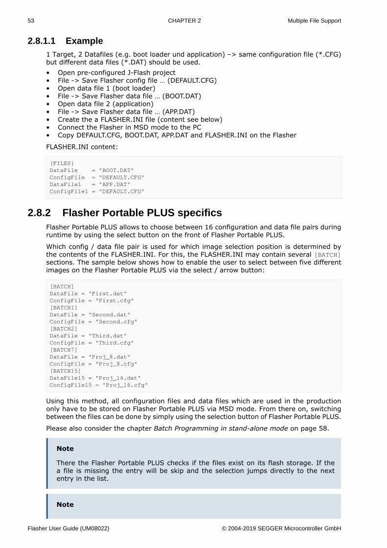
2.8.1.1 Example1 Target, 2 Datafiles (e.g. boot loader und application) –> same configuration file (*.CFG)but different data files (*.DAT) should be used.• Open pre-configured J-Flash project• File -> Save Flasher config file … (DEFAULT.CFG)• Open data file 1 (boot loader)• File -> Save Flasher data file … (BOOT.DAT)• Open data file 2 (application)• File -> Save Flasher data file … (APP.DAT)• Create the a FLASHER.INI file (content see below)• Connect the Flasher in MSD mode to the PC• Copy DEFAULT.CFG, BOOT.DAT, APP.DAT and FLASHER.INI on the Flasher
FLASHER.INI content:
[FILES]DataFile = "BOOT.DAT"ConfigFile = "DEFAULT.CFG"DataFile1 = "APP.DAT"ConfigFile1 = "DEFAULT.CFG"
2.8.2 Flasher Portable PLUS specificsFlasher Portable PLUS allows to choose between 16 configuration and data file pairs duringruntime by using the select button on the front of Flasher Portable PLUS.
Which config / data file pair is used for which image selection position is determined bythe contents of the FLASHER.INI. For this, the FLASHER.INI may contain several [BATCH]sections. The sample below shows how to enable the user to select between five differentimages on the Flasher Portable PLUS via the select / arrow button:
[BATCH]DataFile = "First.dat"ConfigFile = "First.cfg"[BATCH1]DataFile = "Second.dat"ConfigFile = "Second.cfg"[BATCH2]DataFile = "Third.dat"ConfigFile = "Third.cfg"[BATCH7]DataFile = "Proj_8.dat"ConfigFile = "Proj_8.cfg"[BATCH15]DataFile15 = "Proj_16.dat"ConfigFile15 = "Proj_16.cfg"
Using this method, all configuration files and data files which are used in the productiononly have to be stored on Flasher Portable PLUS via MSD mode. From there on, switchingbetween the files can be done by simply using the selection button of Flasher Portable PLUS.
Please also consider the chapter Batch Programming in stand-alone mode on page 58.
Note
There the Flasher Portable PLUS checks if the files exist on its flash storage. If thea file is missing the entry will be skip and the selection jumps directly to the nextentry in the list.
Note
Flasher User Guide (UM08022) © 2004-2019 SEGGER Microcontroller GmbH
54 CHAPTER 2 Multiple File Support
You may have gaps in the list. The missing entries will be skipped when selecting thenext configuration.
Note
The [Files] section is supported by the Flasher Portable PLUS, too. But the numberof configuration is limited to four.
2.8.2.1 Example1 Target, 2 Datafiles (e.g. boot loader und application) –> same configuration file (*.CFG)but different data files (*.DAT) should be used.• Open pre-configured J-Flash project• File -> Save Flasher config file … (DEFAULT.CFG)• Open data file 1 (boot loader)• File -> Save Flasher data file … (BOOT.DAT)• Open data file 2 (application)• File -> Save Flasher data file … (APP.DAT)• Create the a FLASHER.INI file (content see below)• Connect the Flasher in MSD mode to the PC• Copy DEFAULT.CFG, BOOT.DAT, APP.DAT and FLASHER.INI on the Flasher
FLASHER.INI content:
[BATCH]DataFile = "BOOT.DAT"ConfigFile = "DEFAULT.CFG"[BATCH1]DataFile = "APP.DAT"ConfigFile = "DEFAULT.CFG"
Flasher User Guide (UM08022) © 2004-2019 SEGGER Microcontroller GmbH
55 CHAPTER 2 Custom labels
2.9 Custom labelsFlasher supports to assign custom labels to configurations. This allows to specify easy toremember names for configurations that are stored on the Flasher.
2.9.1 Hardware and software requirementsThis feature is supported by the following models:• Flasher Portable PLUS
This feature is supported since V6.30e of the software package and firmware
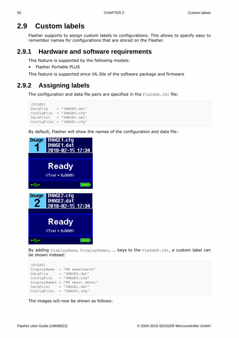
2.9.2 Assigning labelsThe configuration and data file pairs are specified in the FLASHER.INI file:
[FILES]DataFile = "IMAGE0.dat"ConfigFile = "IMAGE0.cfg"DataFile1 = "IMAGE1.dat"ConfigFile1 = "IMAGE1.cfg"
By default, Flasher will show the names of the configuration and data file:
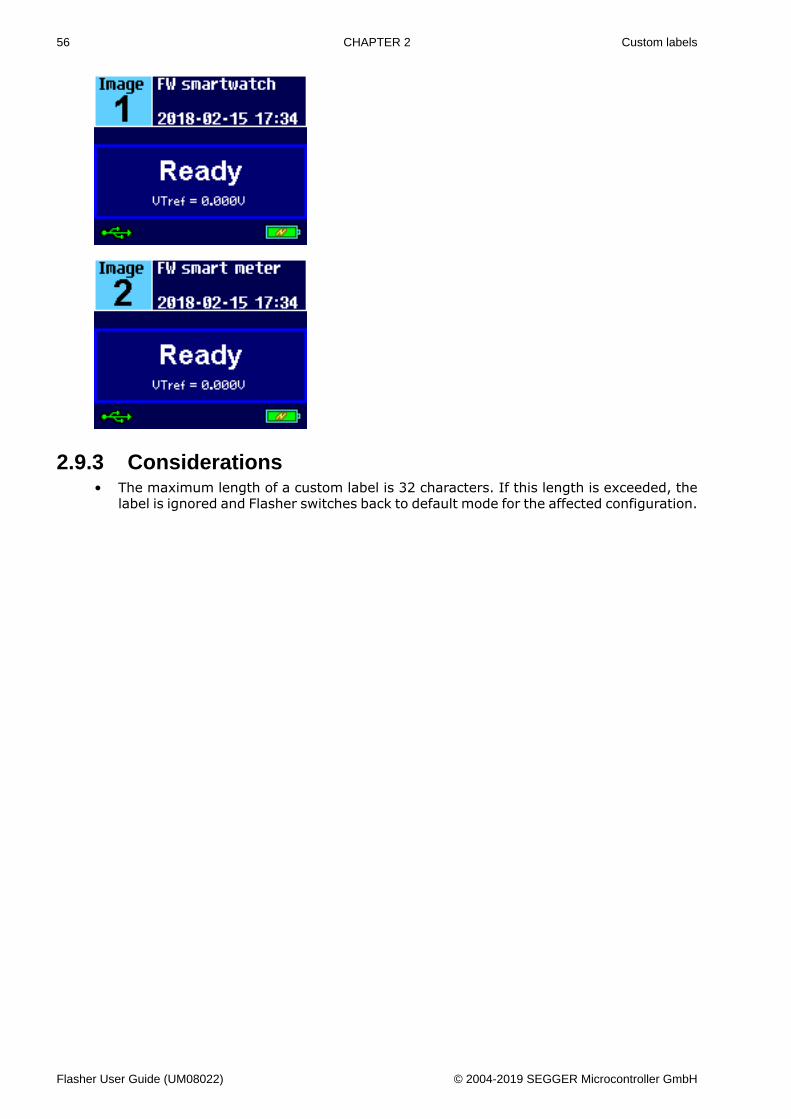
By adding DisplayName, DisplayName1, … keys to the FLASHER.INI, a custom label canbe shown instead:
[FILES]DisplayName = "FW smartwatch"DataFile = "IMAGE0.dat"ConfigFile = "IMAGE0.cfg"DisplayName1 = "FW smart meter"DataFile1 = "IMAGE1.dat"ConfigFile1 = "IMAGE1.cfg"
The images will now be shown as follows:
Flasher User Guide (UM08022) © 2004-2019 SEGGER Microcontroller GmbH
56 CHAPTER 2 Custom labels
2.9.3 Considerations• The maximum length of a custom label is 32 characters. If this length is exceeded, the
label is ignored and Flasher switches back to default mode for the affected configuration.
Flasher User Guide (UM08022) © 2004-2019 SEGGER Microcontroller GmbH
57 CHAPTER 2 Programming multiple targets
2.10 Programming multiple targetsIt is possible to program multiple targets which are located in a JTAG chain. The targetswill be programmed each with a configuration and a data file. The configuration for thedesired target must be selected before it can be programmed, this can be done with the#SELECT command. For more information how to use the #SELECT command please referto Chapter “3.3.5 Commands to Flasher”.
Example
Three devices should be programmed.
JTAG Chain: TDI –> Device2 –> Device1 –> Device0 –> TDO
Three configurations would be stored on the flasher:
Config 0: Configured to program Device0 (DEVICE0.CFG, DEVICE0.DAT)Config 1: Configured to program Device1 (DEVICE1.CFG, DEVICE1.DAT)Config 2: Configured to program Device2 (DEVICE2.CFG, DEVICE2.DAT)
Selection and programming of the target will be done via the ASCII interface:
#SELECT DEVICE0#AUTO#SELECT DEVICE1#AUTO#SELECT DEVICE2#AUTO
2.10.1 Programming multiple targets with J-FlashProgramming multiple targets can also be done via J-Flash using the command line inter-face. For this each target must be handled with its own project file.
Example
JFlash.exe -openproj"Device0.jflash" -open"Device0.hex" -auto -exitJFlash.exe -openproj"Device1.jflash" -open"Device1.hex" -auto -exitJFlash.exe -openproj"Device2.jflash" -open"Device2.hex" -auto -exit
Flasher User Guide (UM08022) © 2004-2019 SEGGER Microcontroller GmbH
58 CHAPTER 2 Batch Programming in stand-alone mode
2.11 Batch Programming in stand-alone modeBatch programming allows to execute different stand-alone mode jobs in batch to be exe-cuted in immediate succession, without any user interaction in between. This can be usedfor example to program multiple targets in a JTAG-Chain or multiple data files to a target.A batch may contains an unlimited number of configurations which consist of a data file(*.DAT) and config file (*.CFG). For further information regarding config and data files,please refer to Preparing for stand-alone operation manually on page 42.In order to specify the batch jobs, a FLASHER.INI file is used. This init file contains a[BATCH] section which describes which configuration pairs (*.DAT and *.CFG file) shouldbe used for each batch job. A sample content of a FLASHER.INI file is shown below:
[BATCH]DataFile = "Flasher0.dat"ConfigFile = "Flasher0.cfg"DataFile1 = "Flasher1.dat"ConfigFile1 = "Flasher1.cfg"
The Flasher Portable PLUS screen will show that the number of jobs contained in the batchand the configuration file name of the first job.
The progress will be shown during the flashing action. The Flasher lists the current job ofthe batch, the current sector address and the percentage of the currently executed action.
The result of the programming will be shown on the screen after finishing all jobs.
Flasher User Guide (UM08022) © 2004-2019 SEGGER Microcontroller GmbH
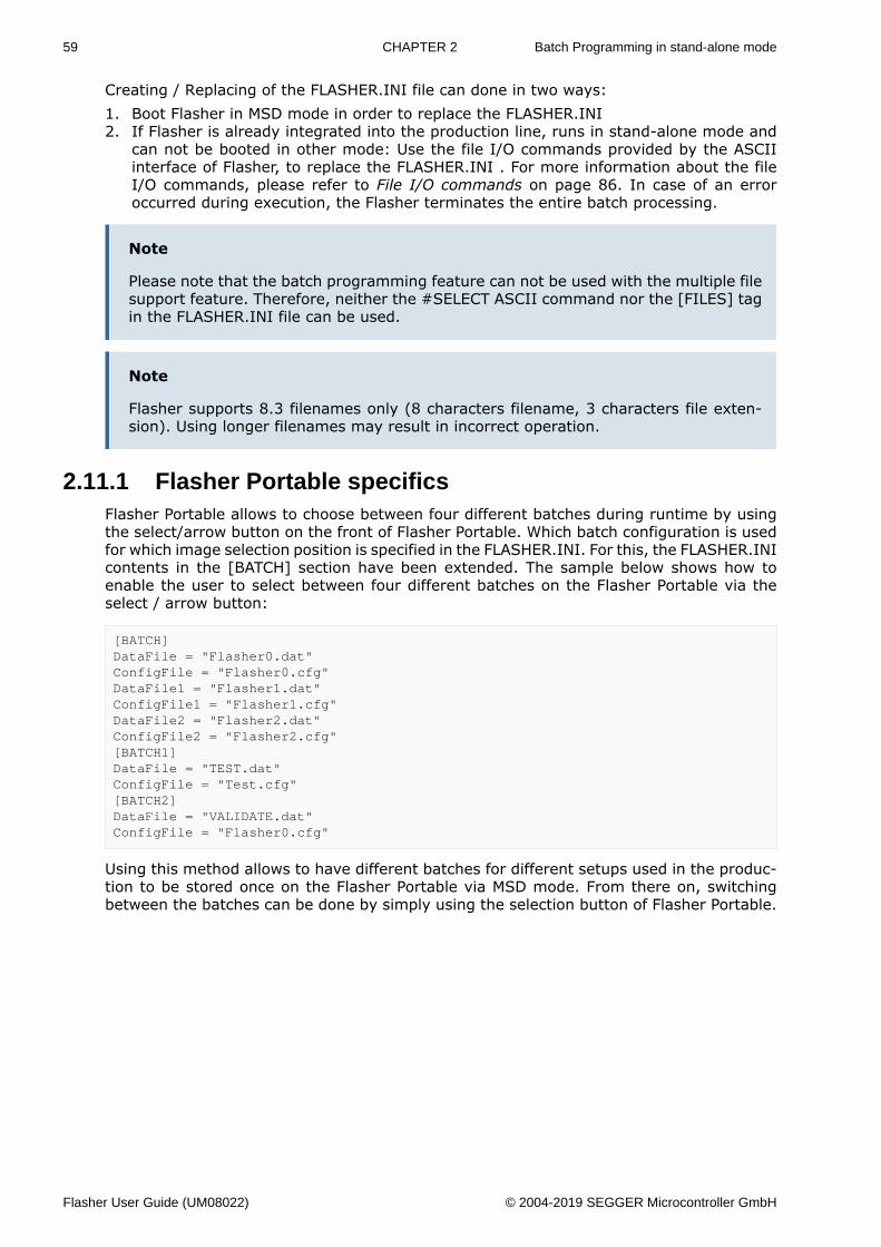
59 CHAPTER 2 Batch Programming in stand-alone mode
Creating / Replacing of the FLASHER.INI file can done in two ways:1. Boot Flasher in MSD mode in order to replace the FLASHER.INI2. If Flasher is already integrated into the production line, runs in stand-alone mode and
can not be booted in other mode: Use the file I/O commands provided by the ASCIIinterface of Flasher, to replace the FLASHER.INI . For more information about the fileI/O commands, please refer to File I/O commands on page 86. In case of an erroroccurred during execution, the Flasher terminates the entire batch processing.
Note
Please note that the batch programming feature can not be used with the multiple filesupport feature. Therefore, neither the #SELECT ASCII command nor the [FILES] tagin the FLASHER.INI file can be used.
Note
Flasher supports 8.3 filenames only (8 characters filename, 3 characters file exten-sion). Using longer filenames may result in incorrect operation.
2.11.1 Flasher Portable specificsFlasher Portable allows to choose between four different batches during runtime by usingthe select/arrow button on the front of Flasher Portable. Which batch configuration is usedfor which image selection position is specified in the FLASHER.INI. For this, the FLASHER.INIcontents in the [BATCH] section have been extended. The sample below shows how toenable the user to select between four different batches on the Flasher Portable via theselect / arrow button:
[BATCH]DataFile = "Flasher0.dat"ConfigFile = "Flasher0.cfg"DataFile1 = "Flasher1.dat"ConfigFile1 = "Flasher1.cfg"DataFile2 = "Flasher2.dat"ConfigFile2 = "Flasher2.cfg"[BATCH1]DataFile = "TEST.dat"ConfigFile = "Test.cfg"[BATCH2]DataFile = "VALIDATE.dat"ConfigFile = "Flasher0.cfg"
Using this method allows to have different batches for different setups used in the produc-tion to be stored once on the Flasher Portable via MSD mode. From there on, switchingbetween the batches can be done by simply using the selection button of Flasher Portable.
Flasher User Guide (UM08022) © 2004-2019 SEGGER Microcontroller GmbH
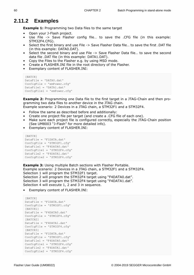
60 CHAPTER 2 Batch Programming in stand-alone mode
2.11.2 ExamplesExample 1: Programming two Data files to the same target• Open your J-Flash project.• Use File -> Save Flasher config file… to save the .CFG file (in this example:
STM32F4.CFG).• Select the first binary and use File -> Save Flasher Data file… to save the first .DAT file
(in this example: DATA0.DAT).• Select the second binary and use File -> Save Flasher Data file… to save the second
data file .DAT file (in this example: DATA1.DAT).• Copy the Files to the Flasher e.g. by using MSD mode.• Create a FLASHER.INI file in the root directory of the Flasher.• Exemplary content of FLASHER.INI:
[BATCH]DataFile = "DATA0.dat"ConfigFile = "emPower.cfg"DataFile1 = "DATA1.dat"ConfigFile1 = "emPower.cfg"
Example 2: Programming one Data file to the first target in a JTAG-Chain and then pro-gramming two data files to another device in the JTAG chain.Example scenario: 2 Devices in a JTAG chain, a STM32F1 and a STM32F4.• Follow the same as described before and additionally:• Create one project file per target (and create a .CFG file of each one).• Make sure each project file is configured correctly, especially the JTAG-Chain position
(See UM8003 “J-Flash” for more detailed info).• Exemplary content of FLASHER.INI:
[BATCH]DataFile = "F1DATA.dat"ConfigFile = "STM32F1.cfg"DataFile1 = "F4DATA0.dat"ConfigFile1 = "STM32F4.cfg"DataFile2 = "F4DATA1.dat"ConfigFile2 = "STM32F4.cfg"
Example 3: Using multiple Batch sections with Flasher Portable.Example scenario: 2 Devices in a JTAG chain, a STM32F1 and a STM32F4.Selection 1 will program the STM32F1 target.Selection 2 will program the STM32F4 target using “F4DATA0.dat”.Selection 3 will program the STM32F4 target using “F4DATA1.dat”.Selection 4 will execute 1, 2 and 3 in sequence.• Exemplary content of FLASHER.INI:
[BATCH]DataFile = "F1DATA.dat"ConfigFile = "STM32F1.cfg"[BATCH1]DataFile = "F4DATA0.dat"ConfigFile = "STM32F4.cfg"[BATCH2]DataFile = "F4DATA1.dat"ConfigFile = "STM32F4.cfg"[BATCH3]DataFile = "F1DATA.dat"ConfigFile = "STM32F1.cfg"DataFile1 = "F4DATA0.dat"ConfigFile1 = "STM32F4.cfg"DataFile2 = "F4DATA1.dat"ConfigFile2 = "STM32F4.cfg"
Flasher User Guide (UM08022) © 2004-2019 SEGGER Microcontroller GmbH
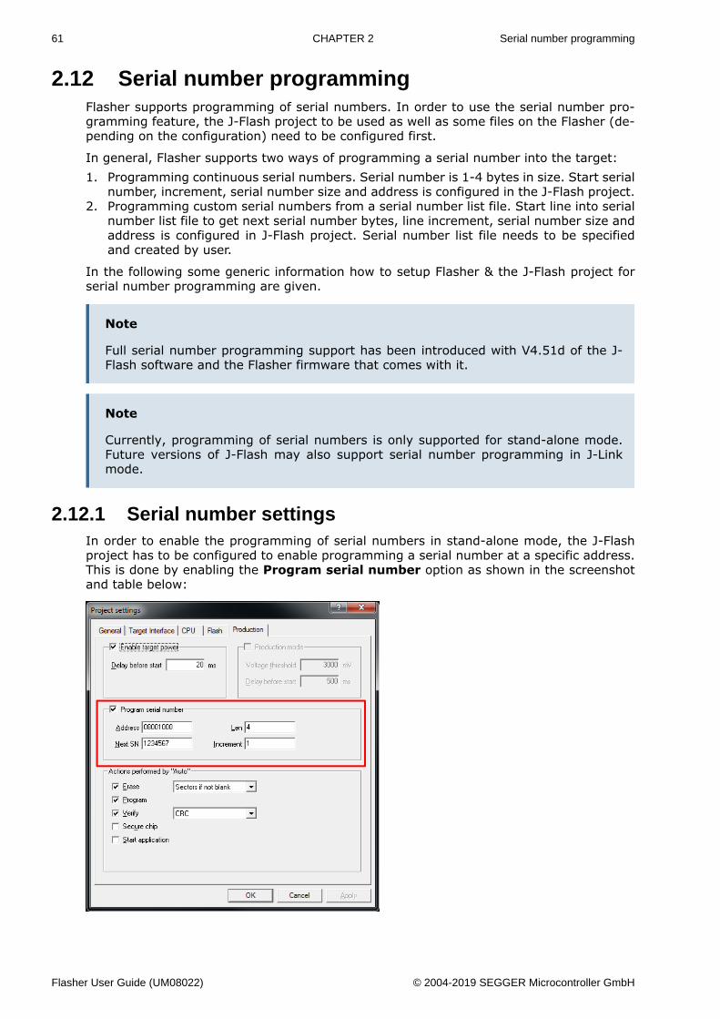
61 CHAPTER 2 Serial number programming
2.12 Serial number programmingFlasher supports programming of serial numbers. In order to use the serial number pro-gramming feature, the J-Flash project to be used as well as some files on the Flasher (de-pending on the configuration) need to be configured first.
In general, Flasher supports two ways of programming a serial number into the target:1. Programming continuous serial numbers. Serial number is 1-4 bytes in size. Start serial
number, increment, serial number size and address is configured in the J-Flash project.2. Programming custom serial numbers from a serial number list file. Start line into serial
number list file to get next serial number bytes, line increment, serial number size andaddress is configured in J-Flash project. Serial number list file needs to be specifiedand created by user.
In the following some generic information how to setup Flasher & the J-Flash project forserial number programming are given.
Note
Full serial number programming support has been introduced with V4.51d of the J-Flash software and the Flasher firmware that comes with it.
Note
Currently, programming of serial numbers is only supported for stand-alone mode.Future versions of J-Flash may also support serial number programming in J-Linkmode.
2.12.1 Serial number settingsIn order to enable the programming of serial numbers in stand-alone mode, the J-Flashproject has to be configured to enable programming a serial number at a specific address.This is done by enabling the Program serial number option as shown in the screenshotand table below:
Flasher User Guide (UM08022) © 2004-2019 SEGGER Microcontroller GmbH
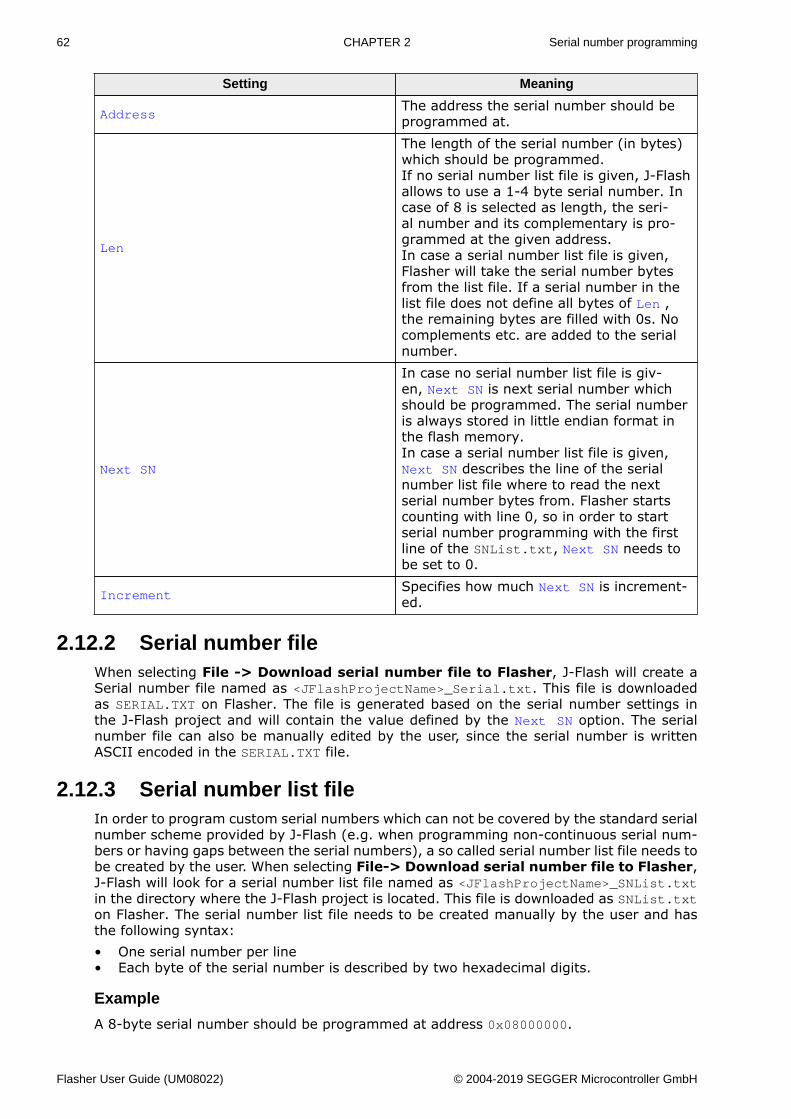
62 CHAPTER 2 Serial number programming
Setting Meaning
AddressThe address the serial number should beprogrammed at.
Len
The length of the serial number (in bytes)which should be programmed.If no serial number list file is given, J-Flashallows to use a 1-4 byte serial number. Incase of 8 is selected as length, the seri-al number and its complementary is pro-grammed at the given address.In case a serial number list file is given,Flasher will take the serial number bytesfrom the list file. If a serial number in thelist file does not define all bytes of Len ,the remaining bytes are filled with 0s. Nocomplements etc. are added to the serialnumber.
Next SN
In case no serial number list file is giv-en, Next SN is next serial number whichshould be programmed. The serial numberis always stored in little endian format inthe flash memory.In case a serial number list file is given,Next SN describes the line of the serialnumber list file where to read the nextserial number bytes from. Flasher startscounting with line 0, so in order to startserial number programming with the firstline of the SNList.txt, Next SN needs tobe set to 0.
IncrementSpecifies how much Next SN is increment-ed.
2.12.2 Serial number fileWhen selecting File -> Download serial number file to Flasher, J-Flash will create aSerial number file named as <JFlashProjectName>_Serial.txt. This file is downloadedas SERIAL.TXT on Flasher. The file is generated based on the serial number settings inthe J-Flash project and will contain the value defined by the Next SN option. The serialnumber file can also be manually edited by the user, since the serial number is writtenASCII encoded in the SERIAL.TXT file.
2.12.3 Serial number list fileIn order to program custom serial numbers which can not be covered by the standard serialnumber scheme provided by J-Flash (e.g. when programming non-continuous serial num-bers or having gaps between the serial numbers), a so called serial number list file needs tobe created by the user. When selecting File-> Download serial number file to Flasher,J-Flash will look for a serial number list file named as <JFlashProjectName>_SNList.txtin the directory where the J-Flash project is located. This file is downloaded as SNList.txton Flasher. The serial number list file needs to be created manually by the user and hasthe following syntax:• One serial number per line• Each byte of the serial number is described by two hexadecimal digits.
Example
A 8-byte serial number should be programmed at address 0x08000000.
Flasher User Guide (UM08022) © 2004-2019 SEGGER Microcontroller GmbH
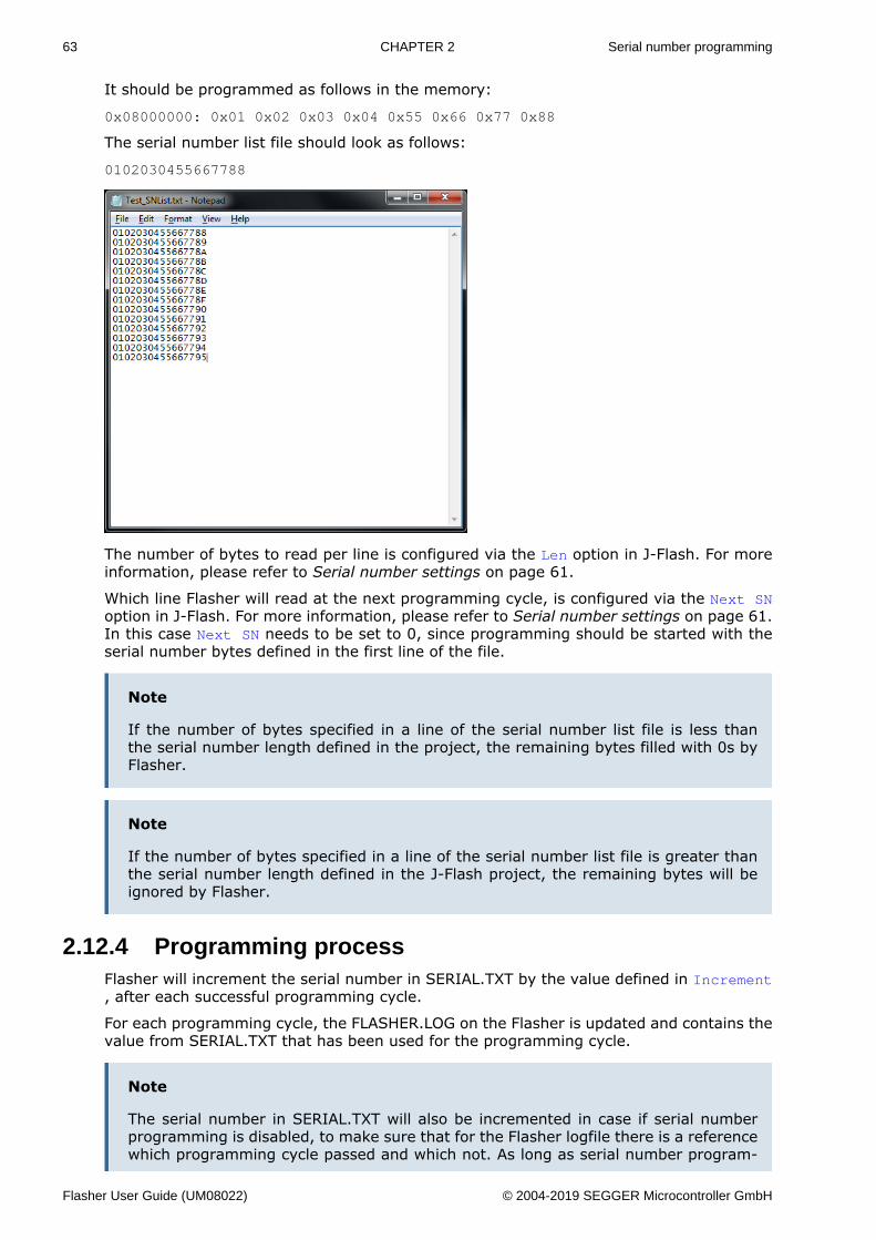
63 CHAPTER 2 Serial number programming
It should be programmed as follows in the memory:
0x08000000: 0x01 0x02 0x03 0x04 0x55 0x66 0x77 0x88
The serial number list file should look as follows:
0102030455667788
The number of bytes to read per line is configured via the Len option in J-Flash. For moreinformation, please refer to Serial number settings on page 61.
Which line Flasher will read at the next programming cycle, is configured via the Next SNoption in J-Flash. For more information, please refer to Serial number settings on page 61.In this case Next SN needs to be set to 0, since programming should be started with theserial number bytes defined in the first line of the file.
Note
If the number of bytes specified in a line of the serial number list file is less thanthe serial number length defined in the project, the remaining bytes filled with 0s byFlasher.
Note
If the number of bytes specified in a line of the serial number list file is greater thanthe serial number length defined in the J-Flash project, the remaining bytes will beignored by Flasher.
2.12.4 Programming processFlasher will increment the serial number in SERIAL.TXT by the value defined in Increment, after each successful programming cycle.
For each programming cycle, the FLASHER.LOG on the Flasher is updated and contains thevalue from SERIAL.TXT that has been used for the programming cycle.
Note
The serial number in SERIAL.TXT will also be incremented in case if serial numberprogramming is disabled, to make sure that for the Flasher logfile there is a referencewhich programming cycle passed and which not. As long as serial number program-
Flasher User Guide (UM08022) © 2004-2019 SEGGER Microcontroller GmbH
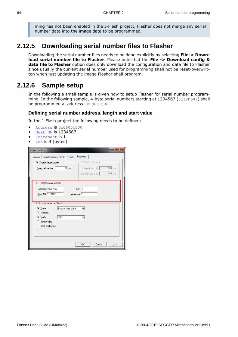
64 CHAPTER 2 Serial number programming
ming has not been enabled in the J-Flash project, Flasher does not merge any serialnumber data into the image data to be programmed.
2.12.5 Downloading serial number files to FlasherDownloading the serial number files needs to be done explicitly by selecting File-> Down-load serial number file to Flasher. Please note that the File -> Download config &data file to Flasher option does only download the configuration and data file to Flashersince usually the current serial number used for programming shall not be reset/overwrit-ten when just updating the image Flasher shall program.
2.12.6 Sample setupIn the following a small sample is given how to setup Flasher for serial number program-ming. In the following sample, 4-byte serial numbers starting at 1234567 (0x12D687) shallbe programmed at address 0x08001000.
Defining serial number address, length and start value
In the J-Flash project the following needs to be defined:• Address is 0x08001000• Next SN is 1234567• Increment is 1• Len is 4 (bytes)
Flasher User Guide (UM08022) © 2004-2019 SEGGER Microcontroller GmbH
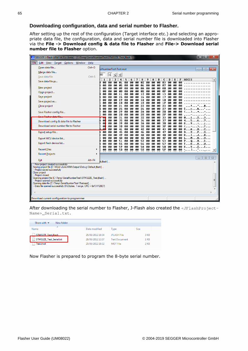
65 CHAPTER 2 Serial number programming
Downloading configuration, data and serial number to Flasher.
After setting up the rest of the configuration (Target interface etc.) and selecting an appro-priate data file, the configuration, data and serial number file is downloaded into Flashervia the File -> Download config & data file to Flasher and File-> Download serialnumber file to Flasher option.
After downloading the serial number to Flasher, J-Flash also created the <JFlashProject-Name>_Serial.txt.
Now Flasher is prepared to program the 8-byte serial number.
Flasher User Guide (UM08022) © 2004-2019 SEGGER Microcontroller GmbH
66 CHAPTER 2 Patch file support
2.13 Patch file supportIn stand-alone mode Flasher supports patch files which allows to patch the content of thedata to be programmed. Before starting programming process in stand-alone mode, Flasherwill look for a file named Patches.txt being present on the Flasher. This file includes thepatches. If this file is present, the number in Serial.txt describes the line number of thePatches.txt that will be used for the current cycle (line counting starts at 0).
Each line in the Patches.txt can hold up to 4 patches, where each patch can be up to32 bytes in length.
Syntax
Each line begins with <NumPatches> followed by each patch <Addr>,<NumBytes>:<Data>in sequence and separated by commas. So the syntax for <NumPatches> = = 4 would beas follows:
<NumPatches>,<Addr>,<NumBytes>:<Data>,<Addr>,<NumBytes>:<Data>,<Addr>,<NumBytes>:<Data>,<Addr>,<NumBytes>:<Data>\r\n
Find below a table which describes each parameter.
Parameter Description
<NumPatches>Describes the number of patches in this patch line. Max. val-ue is 4.
<Addr>Describes the address to be patched. Value is expected inhex.
<NumBytes>Number of bytes for the current patch. Max. value is 20h (32in decimal). Value is expected in hex.
<Data>Describes the data to be patched. <Data> is always expect-ed as 2 hexadecimal characters per byte.
Note
All values are expected in hexadecimal format (hex).<Data> section is always preceded by “:”, not “,”.
Example
Please find below a sample sequence which clarifies the usage of patch files.
Patches.txt, which is located on the Flasher, contains the following line:
3,100025,3:AABBCC,100063,2:DDEE,100078,1:FF
Serial.txt contains a “0” which forces the Flasher to use line 0 from Patches.txt.
After starting the programming cycle, the following data will be patched:
Addr 0x100025: 3 byte 0xAA 0xBB 0xCCAddr 0x100063: 2 byte 0xDD 0xEEAddr 0x100078: 1 byte 0xFF
Single patch via RS232
Alternatively, you can start a programming cycle with patch data that is only valid for thisone cycle (no need for a Patches.txt file):
Send the #AUTO PATCH <NumPatches>,<Addr>,<NumBytes>:<Data>
command via Flasher ASCII interface. The parameters have the same function as describedin the table above.
Flasher User Guide (UM08022) © 2004-2019 SEGGER Microcontroller GmbH
67 CHAPTER 2 Limiting the number of programming cycles
2.14 Limiting the number of programming cyclesFlasher provides a mechanism to limit the number of programming cycles that can beperformed in stand-alone mode with the configuration that is stored on the Flasher. Tomake use of this feature, a file called Cntdown.txt needs to be placed on the Flasher. Thisfile simply contains a decimal number (32-bit unsigned integer) that describes how manyprogramming cycles can be performed with the current setup.
This feature especially makes sense when used in combination with authorized flashing.For more information about authorized flashing, please refer to Authorized flashing onpage 68.
Note
The number in the Cntdown.txt is only updated on a successful programming cycle.Programming cycles that failed, do not affect the Cntdown.txt.
2.14.1 Changed fail/error LED indicator behaviorIn case a Cntdown.txt is found at boot time, the fail/error LED of Flasher behaves differentfrom normal. If the number of programming cycles left is 10 or below, the following willhappen:• The red error/fail LED will lit for 1 second• After this, it will blink/toggle x times @ 5 Hz, indicating the number of programming
cycles left. (blinking 5 times for 5 cycles left, …)
2.14.2 Required Flasher hardware version for Cntdown.txtsupport
Older Flasher models do not support the limiting of programming cycles. The Flashers withthe following serial number ranges do not support limiting of programming cycles:• 1621xxxxx (Flasher ARM V2)• 1630xxxxx (Flasher ARM V3)• 4210xxxxx (Flasher PPC V1)• 4110xxxxx (Flasher RX V1)
All other models / hardware versions support limiting of programming cycles.
Flasher User Guide (UM08022) © 2004-2019 SEGGER Microcontroller GmbH
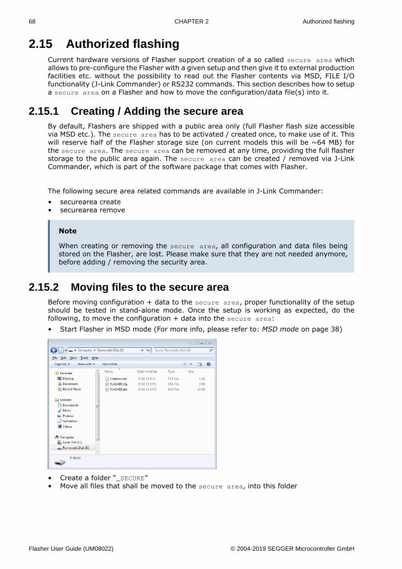
68 CHAPTER 2 Authorized flashing
2.15 Authorized flashingCurrent hardware versions of Flasher support creation of a so called secure area whichallows to pre-configure the Flasher with a given setup and then give it to external productionfacilities etc. without the possibility to read out the Flasher contents via MSD, FILE I/Ofunctionality (J-Link Commander) or RS232 commands. This section describes how to setupa secure area on a Flasher and how to move the configuration/data file(s) into it.
2.15.1 Creating / Adding the secure areaBy default, Flashers are shipped with a public area only (full Flasher flash size accessiblevia MSD etc.). The secure area has to be activated / created once, to make use of it. Thiswill reserve half of the Flasher storage size (on current models this will be ~64 MB) forthe secure area. The secure area can be removed at any time, providing the full flasherstorage to the public area again. The secure area can be created / removed via J-LinkCommander, which is part of the software package that comes with Flasher.
The following secure area related commands are available in J-Link Commander:• securearea create• securearea remove
Note
When creating or removing the secure area, all configuration and data files beingstored on the Flasher, are lost. Please make sure that they are not needed anymore,before adding / removing the security area.
2.15.2 Moving files to the secure areaBefore moving configuration + data to the secure area, proper functionality of the setupshould be tested in stand-alone mode. Once the setup is working as expected, do thefollowing, to move the configuration + data into the secure area:• Start Flasher in MSD mode (For more info, please refer to: MSD mode on page 38)
• Create a folder “_SECURE”• Move all files that shall be moved to the secure area, into this folder
Flasher User Guide (UM08022) © 2004-2019 SEGGER Microcontroller GmbH
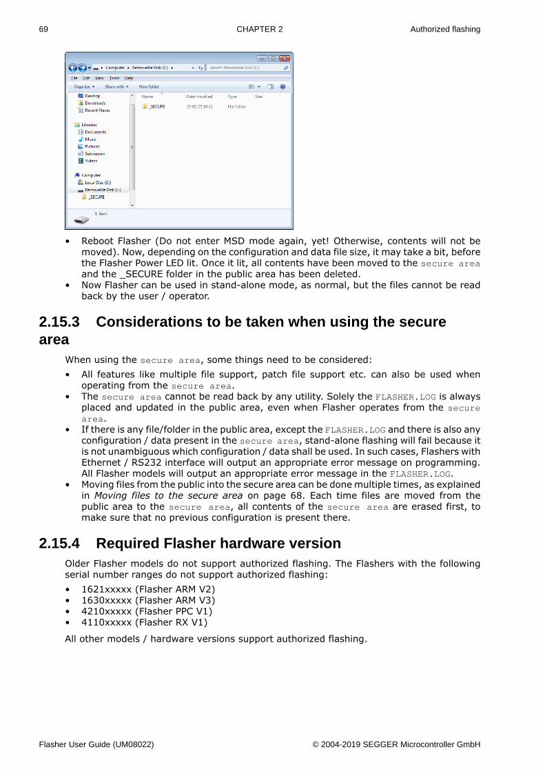
69 CHAPTER 2 Authorized flashing
• Reboot Flasher (Do not enter MSD mode again, yet! Otherwise, contents will not bemoved). Now, depending on the configuration and data file size, it may take a bit, beforethe Flasher Power LED lit. Once it lit, all contents have been moved to the secure areaand the _SECURE folder in the public area has been deleted.
• Now Flasher can be used in stand-alone mode, as normal, but the files cannot be readback by the user / operator.
2.15.3 Considerations to be taken when using the securearea
When using the secure area, some things need to be considered:• All features like multiple file support, patch file support etc. can also be used when
operating from the secure area.• The secure area cannot be read back by any utility. Solely the FLASHER.LOG is always
placed and updated in the public area, even when Flasher operates from the securearea.
• If there is any file/folder in the public area, except the FLASHER.LOG and there is also anyconfiguration / data present in the secure area, stand-alone flashing will fail because itis not unambiguous which configuration / data shall be used. In such cases, Flashers withEthernet / RS232 interface will output an appropriate error message on programming.All Flasher models will output an appropriate error message in the FLASHER.LOG.
• Moving files from the public into the secure area can be done multiple times, as explainedin Moving files to the secure area on page 68. Each time files are moved from thepublic area to the secure area, all contents of the secure area are erased first, tomake sure that no previous configuration is present there.
2.15.4 Required Flasher hardware versionOlder Flasher models do not support authorized flashing. The Flashers with the followingserial number ranges do not support authorized flashing:• 1621xxxxx (Flasher ARM V2)• 1630xxxxx (Flasher ARM V3)• 4210xxxxx (Flasher PPC V1)• 4110xxxxx (Flasher RX V1)
All other models / hardware versions support authorized flashing.
Flasher User Guide (UM08022) © 2004-2019 SEGGER Microcontroller GmbH
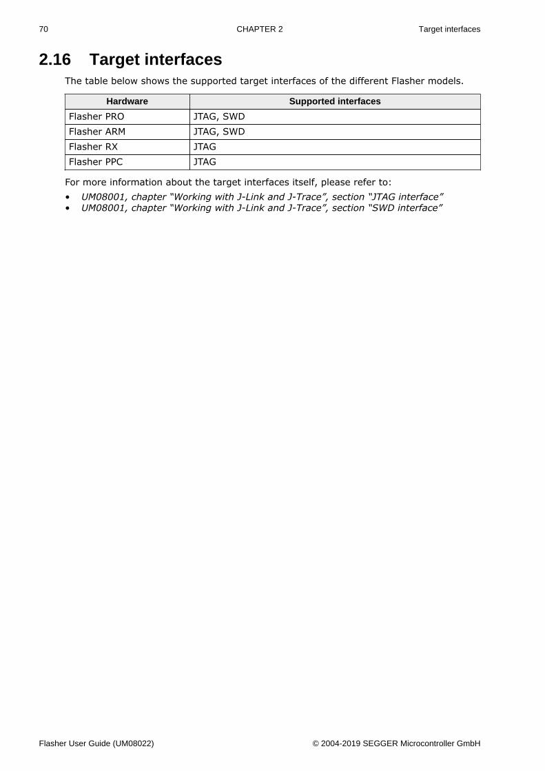
70 CHAPTER 2 Target interfaces
2.16 Target interfacesThe table below shows the supported target interfaces of the different Flasher models.
Hardware Supported interfaces
Flasher PRO JTAG, SWDFlasher ARM JTAG, SWDFlasher RX JTAGFlasher PPC JTAG
For more information about the target interfaces itself, please refer to:• UM08001, chapter “Working with J-Link and J-Trace”, section “JTAG interface”• UM08001, chapter “Working with J-Link and J-Trace”, section “SWD interface”
Flasher User Guide (UM08022) © 2004-2019 SEGGER Microcontroller GmbH
71 CHAPTER 2 Supported microcontrollers
2.17 Supported microcontrollers
2.17.1 FlasherFlasher supports download into the internal flash of a large number of microcontrollers. Thenumber of supported devices is steadily growing, so you can always find the latest list ofsupported devices on our website:
http://www.segger.com/supported-devices.html
Flasher User Guide (UM08022) © 2004-2019 SEGGER Microcontroller GmbH
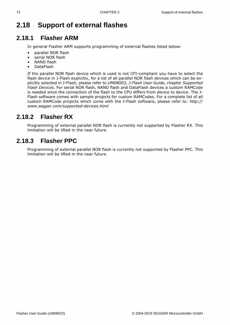
72 CHAPTER 2 Support of external flashes
2.18 Support of external flashes
2.18.1 Flasher ARMIn general Flasher ARM supports programming of external flashes listed below:• parallel NOR flash• serial NOR flash• NAND flash• DataFlash
If the parallel NOR flash device which is used is not CFI-compliant you have to select theflash device in J-Flash explicitly, for a list of all parallel NOR flash devices which can be ex-plicitly selected in J-Flash, please refer to UM08003, J-Flash User Guide, chapter SupportedFlash Devices. For serial NOR flash, NAND flash and DataFlash devices a custom RAMCodeis needed since the connection of the flash to the CPU differs from device to device. The J-Flash software comes with sample projects for custom RAMCodes. For a complete list of allcustom RAMCode projects which come with the J-Flash software, please refer to: http://www.segger.com/supported-devices.html
2.18.2 Flasher RXProgramming of external parallel NOR flash is currently not supported by Flasher RX. Thislimitation will be lifted in the near future.
2.18.3 Flasher PPCProgramming of external parallel NOR flash is currently not supported by Flasher PPC. Thislimitation will be lifted in the near future.
Flasher User Guide (UM08022) © 2004-2019 SEGGER Microcontroller GmbH
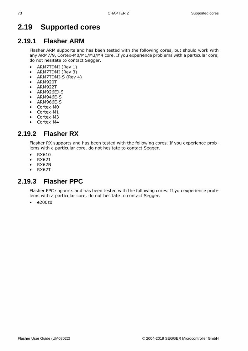
73 CHAPTER 2 Supported cores
2.19 Supported cores
2.19.1 Flasher ARMFlasher ARM supports and has been tested with the following cores, but should work withany ARM7/9, Cortex-M0/M1/M3/M4 core. If you experience problems with a particular core,do not hesitate to contact Segger.• ARM7TDMI (Rev 1)• ARM7TDMI (Rev 3)• ARM7TDMI-S (Rev 4)• ARM920T• ARM922T• ARM926EJ-S• ARM946E-S• ARM966E-S• Cortex-M0• Cortex-M1• Cortex-M3• Cortex-M4
2.19.2 Flasher RXFlasher RX supports and has been tested with the following cores. If you experience prob-lems with a particular core, do not hesitate to contact Segger.• RX610• RX621• RX62N• RX62T
2.19.3 Flasher PPCFlasher PPC supports and has been tested with the following cores. If you experience prob-lems with a particular core, do not hesitate to contact Segger.• e200z0
Flasher User Guide (UM08022) © 2004-2019 SEGGER Microcontroller GmbH
74 CHAPTER 2 Newline encoding
2.20 Newline encodingIn general, for all patch files, init files etc. Flasher supports both newline encodings:• Windows: \r\n• Unix/Mac: \n
All parser functionality etc. are written to be independent from the host operating system.
Flasher User Guide (UM08022) © 2004-2019 SEGGER Microcontroller GmbH
75 CHAPTER 2 Programming multiple targets in parallel
2.21 Programming multiple targets in parallelTo program multiple targets in parallel, a Flasher ATE or multiple Flashers will be needed(each connecting to one CPU). The Flasher ATE can be used to program up to 10 targets inparallel by using a single control unit. For further information regarding Flasher ATE, pleaserefer to the Flasher ATE user manual (UM08035_FlasherATE.pdf).
Using multiple Flashers, this can be done using the production programming soft-ware J-Flash. For further information, please refer to Chapter “Command Line Inter-face” Sub-chapter “Programming multiple targets in parallel” of the J-Flash User Guide(UM08003_JFlash.pdf) which is part of the J-Link Software and Documentation package.
Flasher User Guide (UM08022) © 2004-2019 SEGGER Microcontroller GmbH
Chapter 3 TCP Services
This chapter describes the integrated TCP services.
Flasher User Guide (UM08022) © 2004-2019 SEGGER Microcontroller GmbH
77 CHAPTER 3 FTP Server
3.1 FTP ServerThe FTP server provides easy access to the files on the internal file system. The serversupports a maximum of 2 simultaneous connections and works with all common FTP clients.
3.1.1 Access dataAnonymous access to the FTP server is limited to read-only access to the file system.For write access, special login credentials have to be used:
Login: adminPassword: 1234
Note
The access data for read/write access can not be modified and it is intended to beused only as a convenience feature to avoid unintended modification of the Flasher’sfile system. It is not meant as a security feature.
Flasher User Guide (UM08022) © 2004-2019 SEGGER Microcontroller GmbH
78 CHAPTER 3 Web server
3.2 Web serverAll Flashers which come with an Ethernet interface also come with a built-in web server,which provides a web interface for information and network configuration. For the network,the IP address settings can be changed and a nick name can be assigned to the device.
Additionally, the web interface provides information about the status of the integrated op-erating system, the IP stack and the target hardware.
Flasher User Guide (UM08022) © 2004-2019 SEGGER Microcontroller GmbH
Chapter 4 Remote control
This chapter describes how to control Flasher via the 9-pin serial interface connector or viathe integrated Telnet interface.
Flasher User Guide (UM08022) © 2004-2019 SEGGER Microcontroller GmbH
80 CHAPTER 4 Overview
4.1 OverviewThere are 3 ways to control Flasher operation:• Manual: Programming operation starts when pressing the button. The LEDs serve as
visible indicators.• Via Handshake lines: 3 lines on the serial interface are used:
1 line is an input and can be used to start operation,2 lines are outputs and serve as busy and status signals.
• Terminal communication via RS232.• Terminal communication via Telnet.
Note
All ways to control Flasher operation are working only if Flasher is in standalone mode.In J-Link / MSD mode they have no effect.
Flasher User Guide (UM08022) © 2004-2019 SEGGER Microcontroller GmbH
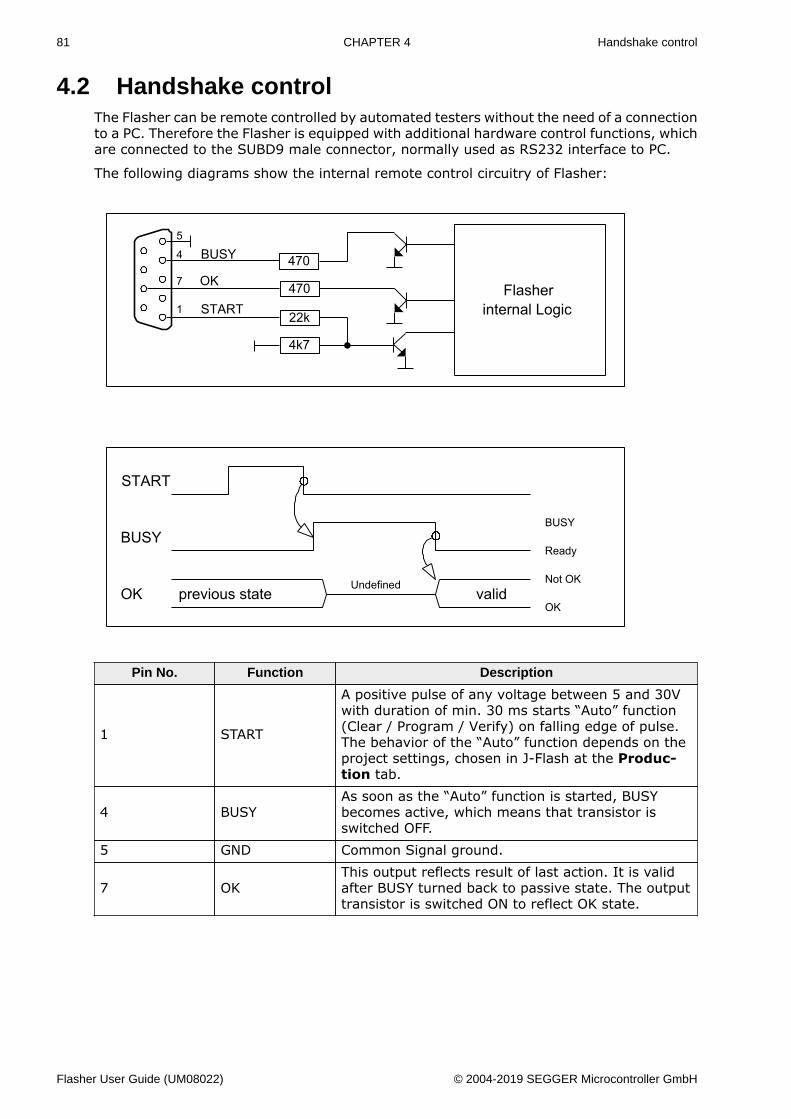
81 CHAPTER 4 Handshake control
4.2 Handshake controlThe Flasher can be remote controlled by automated testers without the need of a connectionto a PC. Therefore the Flasher is equipped with additional hardware control functions, whichare connected to the SUBD9 male connector, normally used as RS232 interface to PC.
The following diagrams show the internal remote control circuitry of Flasher:
Pin No. Function Description
1 START
A positive pulse of any voltage between 5 and 30Vwith duration of min. 30 ms starts “Auto” function(Clear / Program / Verify) on falling edge of pulse.The behavior of the “Auto” function depends on theproject settings, chosen in J-Flash at the Produc-tion tab.
4 BUSYAs soon as the “Auto” function is started, BUSYbecomes active, which means that transistor isswitched OFF.
5 GND Common Signal ground.
7 OKThis output reflects result of last action. It is validafter BUSY turned back to passive state. The outputtransistor is switched ON to reflect OK state.
Flasher User Guide (UM08022) © 2004-2019 SEGGER Microcontroller GmbH
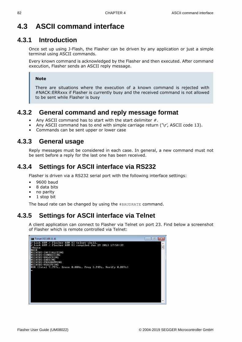
82 CHAPTER 4 ASCII command interface
4.3 ASCII command interface
4.3.1 IntroductionOnce set up using J-Flash, the Flasher can be driven by any application or just a simpleterminal using ASCII commands.
Every known command is acknowledged by the Flasher and then executed. After commandexecution, Flasher sends an ASCII reply message.
Note
There are situations where the execution of a known command is rejected with#NACK:ERRxxx if Flasher is currently busy and the received command is not allowedto be sent while Flasher is busy
4.3.2 General command and reply message format• Any ASCII command has to start with the start delimiter #.• Any ASCII command has to end with simple carriage return (’\r’, ASCII code 13).• Commands can be sent upper or lower case
4.3.3 General usageReply messages must be considered in each case. In general, a new command must notbe sent before a reply for the last one has been received.
4.3.4 Settings for ASCII interface via RS232Flasher is driven via a RS232 serial port with the following interface settings:• 9600 baud• 8 data bits• no parity• 1 stop bit
The baud rate can be changed by using the #BAUDRATE command.
4.3.5 Settings for ASCII interface via TelnetA client application can connect to Flasher via Telnet on port 23. Find below a screenshotof Flasher which is remote controlled via Telnet:
Flasher User Guide (UM08022) © 2004-2019 SEGGER Microcontroller GmbH
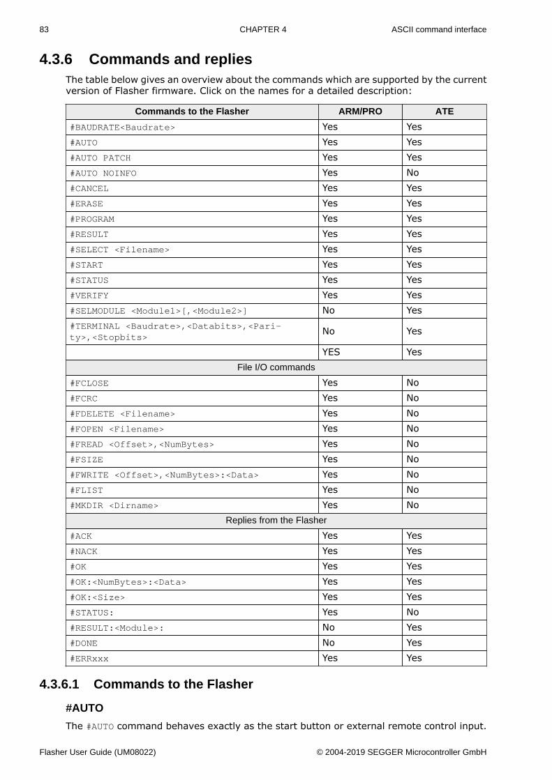
83 CHAPTER 4 ASCII command interface
4.3.6 Commands and repliesThe table below gives an overview about the commands which are supported by the currentversion of Flasher firmware. Click on the names for a detailed description:
Commands to the Flasher ARM/PRO ATE
#BAUDRATE<Baudrate> Yes Yes#AUTO Yes Yes#AUTO PATCH Yes Yes#AUTO NOINFO Yes No#CANCEL Yes Yes#ERASE Yes Yes#PROGRAM Yes Yes#RESULT Yes Yes#SELECT <Filename> Yes Yes#START Yes Yes#STATUS Yes Yes#VERIFY Yes Yes#SELMODULE <Module1>[,<Module2>] No Yes#TERMINAL <Baudrate>,<Databits>,<Pari-ty>,<Stopbits>
No Yes
YES YesFile I/O commands
#FCLOSE Yes No#FCRC Yes No#FDELETE <Filename> Yes No#FOPEN <Filename> Yes No#FREAD <Offset>,<NumBytes> Yes No#FSIZE Yes No#FWRITE <Offset>,<NumBytes>:<Data> Yes No#FLIST Yes No#MKDIR <Dirname> Yes No
Replies from the Flasher
#ACK Yes Yes#NACK Yes Yes#OK Yes Yes#OK:<NumBytes>:<Data> Yes Yes#OK:<Size> Yes Yes#STATUS: Yes No#RESULT:<Module>: No Yes#DONE No Yes#ERRxxx Yes Yes
4.3.6.1 Commands to the Flasher
#AUTO
The #AUTO command behaves exactly as the start button or external remote control input.
Flasher User Guide (UM08022) © 2004-2019 SEGGER Microcontroller GmbH
84 CHAPTER 4 ASCII command interface
Usually, the following command sequence will be performed when receiving the #AUTOcommand:• The Flasher erases the target CPU (if not blank)• The Flasher programs the target CPU• The Flasher verifies the target CPU
Depending on the settings chosen in the Production tab in J-Flash, this sequence can differfrom the one shown above.
Finally, Flasher responds with• #OK if no error occurred• #ERRxxx if any error occurred during operation. xxx represents the error code, normally
replied to Flasher PC program. The #ERRxxx message may be followed by an additionalerror text.
During execution of the #AUTO command, Flasher automatically sends “status” messagesvia RS232 to reflect the state of execution. Typically during execution of #AUTO command,Flasher will reply the following sequence of messages:
#ACK#STATUS:INITIALIZING#STATUS:CONNECTING#STATUS:UNLOCKING#STATUS:ERASING#STATUS:PROGRAMMING#STATUS:VERIFYING#OK (Total 13.993s, Erase 0.483s, Prog 9.183s, Verify 2.514s)
#AUTO PATCH
The #AUTO PATCH command allows patching of the content of the data to be programmed.
Flasher responds with• #OK if no error occurred• #ERRxxx if any error occurred during operation. xxx represents the error code, normally
replied to Flasher PC program. The #ERRxxx message may be followed by an additionalerror text.
For further information about the usage of the #AUTO PATCH command please refer to Patchfile support on page 66.
#AUTO NOINFO
This command may be used instead of #AUTO, if no status messages from Flasher shouldbe sent during execution. The NOINFO extension is also available for all other commands.
The command ends with #OK or #ERRxxx
#BAUDRATE<Baudrate>
This command can be sent in order to change the baud rate of the Flasher’s RS232 interfaceused for communication. <Baudrate> is expected in decimal format.
If this command succeeds, Flasher responds with:
#ACK#OK
Otherwise it will respond with one of the following error messages:
#ERR255: Invalid parametersor#ERR255: Baudrate is not supported
Note
Flasher User Guide (UM08022) © 2004-2019 SEGGER Microcontroller GmbH
85 CHAPTER 4 ASCII command interface
After sending the #BAUDRATE command you will first have to wait until the Flasherresponds with the #OK message. It is recommended wait 5ms before sending the nextcommand with the new baudrate in order to give the Flasher the time to change thebaudrate.
#CANCEL
This command can be sent to abort a running program. It may take a while until the currentprogram is actually canceled.
Flasher will respond with:
#ERR007:CANCELED.
#ERASE
This command can be sent to erase all selected target flash sectors.
Flasher will reply the following sequence of messages:
#ACK#STATUS:INITIALIZING#STATUS:CONNECTING#STATUS:UNLOCKING#STATUS:ERASING#OK (Total 0.893s, Erase 0.483s)
#PROGRAM
This command can be used instead of #AUTO to program a target without erasing the targetbefore programming and without performing a final verification.
#RESULT
This command can be sent any time, even during other command execution. Flasher re-sponds with the last result of the previously executed command.
#SELECT <Filename>
The #SELECT command is used to select a specific config and data file pair which should beused by Flasher to program the target. <Filename> specifies the name of file pair withoutextensions (.CFG and .DAT) on the Flasher which should be selected. Flasher saves theselected config and data file in the FLASHER.INI file. So this selection is remembered evenbetween power-cycling Flasher.
This may be verfy helpful in cases where several config and data files are stored on Flasher.The user can easily switch between these config and data files without connecting Flasherto a host.
If this command succeeds, Flasher responds with:
#ACK#OK
Find below a sample sequence which shows how to use the #SELECT command:
#SELECT ATSAM7_1 // ATSAM7_1.CFG and ATSAM7_1.DAT is selected#ACK#OK#AUTO // Start auto programming#ACK#STATUS:INITIALIZING#STATUS:CONNECTING#STATUS:UNLOCKING#STATUS:ERASING#STATUS:PROGRAMMING#STATUS:VERIFYING
Flasher User Guide (UM08022) © 2004-2019 SEGGER Microcontroller GmbH
86 CHAPTER 4 ASCII command interface
#OK (Total 8.416s, Erase 0.005s, Prog 6.845s, Verify 0.959s)#SELECT ATSAM7_2 // ATSAM7_2.CFG and ATSAM7_2.DAT is selected#ACK#OK#AUTO // Start auto programming#ACK#STATUS:INITIALIZING#STATUS:CONNECTING#STATUS:UNLOCKING#STATUS:ERASING#STATUS:PROGRAMMING#STATUS:VERIFYING#OK (Total 8.632s, Erase 0.005s, Prog 7.051s, Verify 0.969s)
#START
This command can be sent to release Flasher’s target interface. All signals from Flasherto target will be set into high-Z mode, reset of target will be released. It may be used tostart target application program.
Flasher will reply with the following sequence of messages:
#ACK#STATUS:INITIALIZING#STATUS:CONNECTING#OK (Total 1.148s)
#STATUS
This command can be sent any time, even during other command execution. Flasher re-sponds with its current state. All defined state messages are described under Replies fromFlasher on page 89.
#VERIFY
This command can used to verify the target flash content against the data stored in Flasher.
4.3.6.2 File I/O commandsThe ASCII interface of the Flasher also supports file I/O operations.
The following file I/O commands are supported:
#FCLOSE
The #FCLOSE command closes the file on Flasher which was opened via #FOPEN. After thiscommand has been issued further file I/O operations except #FDELETE are not allowed untilthe #FOPEN command is send again.
A typical sequence when using the #FCLOSE command does look like as follows:
#FCLOSE#ACK#OK
Note
When using the #FCLOSE command a file has to be open (previously opened by#FOPEN). Otherwise Flasher will respond with the following if no file has been opened:
#ACK#ERR255:No file opened
Flasher User Guide (UM08022) © 2004-2019 SEGGER Microcontroller GmbH
87 CHAPTER 4 ASCII command interface
#FCRC
The #FCRC command calculates a 32-bit CRC of the given file. This CRC can be used to verifyfile integrity. This command should not be used while a file has been opened via #FOPEN.The CRC will be also reported by J-Flash when downloading or saving files via J-Flash.
A typical sequence when using the #FCRC command does look like as follows:
#FCRC flasher.dat#ACK#OK:0x75BC855A
#FDELETE <Filename>
The #FDELETE command is used to delete a file on Flasher where <Filename> specifies thename of the file.
A typical sequence when using the #FDELETE command does look like as follows:
#FDELETE flasher.dat#ACK#OK
Note
If deletion of the file fails for example if the file does not exist, Flasher will respondwith the following sequence:
#ACK#ERR255:Failed to delete file
#FOPEN <Filename>
The #FOPEN command is used to open a file on Flasher for further file I/O operations.<Filename> specifies the file on the Flasher which should be opened. If <Filename> cannot be found on Flasher a new one will be created.
A typical sequence using the #FOPEN command does look like as follows:
#FOPEN flasher.dat#ACK#OK
Note
Currently only one file can be open at the same time. If #FOPEN is send and anotherfile is already open, Flasher will respond with:
#ACK#ERR255:A file has already been opened
#FREAD <Offset>,<NumBytes>
The #FREAD command is used to read data from a file on Flasher. <Offset> specifies theoffset in the file, at which data reading is started. <NumBytes> specifies the number of byteswhich should be read.
A typical sequence when using the #FREAD command does look like as follows:
#FREAD 0,4#ACK#OK:04:466c6173
If the #FREAD command succeeds, Flasher will finally respond with a #OK:<NumBytes>:<Da-ta> reply message. For more information about the Flasher reply messages, please referto Replies from Flasher on page 89.
Flasher User Guide (UM08022) © 2004-2019 SEGGER Microcontroller GmbH
88 CHAPTER 4 ASCII command interface
Note
In order to use the #FREAD command. A file has to be opened before, via the #FOPENcommand. Otherwise Flasher will respond with the following sequence:
#ACK#ERR255:No file opened
#FSIZE
The #FSIZE command is used to get the size of the currently opened file on Flasher.
A typical sequence when using the #FSIZE command does look like as follows:
#FSIZE#ACK#OK:10 // file on flasher which is currently open, has a size of 16 bytes
If the #FSIZE command succeeds, Flasher will respond with a #OK:<Size> reply message.For more information about the Flasher reply messages, please refer to Replies from Flasheron page 89.
Note
In order to use the #FREAD command. A file has to be opened before, via the #FOPENcommand. Otherwise Flasher will respond with the following sequence:
#ACK#ERR255:No file opened
#FWRITE <Offset>,<NumBytes>:<Data>
The #FWRITE command is used to write to a file on Flasher. <Offset> specifies the offset inthe file, at which data writing is started. <NumBytes> specifies the number of bytes whichare send with this command and which are written into the file on Flasher. <NumBytes>is limited to 512 bytes at once. This means, if you want to write e.g. 1024 bytes, youhave to send the #FWRITE command twice, using an appropriate offset when sending itthe second time.
<Offset> and <NumBytes> are expected in hexadecimal format.
#FWRITE 0,200:<Data>#FWRITE 200,200:<Data>
The data is expected in hexadecimal format (two hexadecimal characters per byte). Thefollowing example illustrates the use of #FWRITE:
Data to be send: Hello !ASCII values: 0x48, 0x65, 0x6C, 0x6C, 0x6F, 0x20, 0x21
#FWRITE 0,7:48656C6C6F2021
Note
In order to use the #FWRITE command a file has to be opened via the #FOPEN command,first. Otherwise Flasher will respond with the following sequence:
#ACK#ERR255:No file opened
#FLIST
The #LIST command is used to list all files stored on the Flasher.
Flasher User Guide (UM08022) © 2004-2019 SEGGER Microcontroller GmbH
89 CHAPTER 4 ASCII command interface
A typical sequence using the #FLIST command does look like as follows:
#FLIST#ACKFLASHER.INI Size: 60SERIAL.TXT Size: 3FLASHER.LOG Size: 207FOLDER (DIR)FOLDER\TEST1.CFG Size: 2048FOLDER\TEST1.DAT Size: 12288#OK
#MKDIR <Dirname>
The #MKDIR command is used to create a directory on Flasher. <Dirname> specifies thename of the new directory. <Dirname> may also specify a path to create a subdirectory.
A typical sequence using the #MKDIR command does look like as follows:
#MKDIR folder#ACK#OK
Note
If the directory can not be created because of a bad <Dirname> argument, Flasherwill respond with:
#ACK#ERR255:Failed to create directory
4.3.6.3 Replies from FlasherThe reply messages from Flasher follow the same data format as commands. Any replymessage starts with ASCII start delimiter #, ends with simple carriage return (ASCII code13) and is sent in uppercase. In contrast to commands, replies can be followed by a de-scriptive message, which gives more detailed information about the reply. This descriptionis sent in mixed case. The #OK reply, for example, is such a reply. It is followed by a stringcontaining information about the performance time needed for the operations:
#OK (Total 13.993s, Erase 0.483s, Prog 9.183s, Verify 2.514s)
The following reply messages from Flasher are defined:
#ACK
Flasher replies with #ACK message on reception of any defined command before the com-mand itself is executed.
#NACK
Flasher replies with #NACK, if an undefined command was received.
#OK
Flasher replies with #OK, if a command other than #STATUS or #RESULT was executed andended with no error.
#OK:<NumBytes>:<Data>
Flasher replies with #OK:<Len>:<Data> if a #FREAD command was executed. <NumBytes>is the number of bytes which could be read. This value may differ from the number ofrequested bytes, for example if more bytes than available, were requested. <NumBytes>and <Data> are send in hexadecimal format (for <Data>: two hexadecimal characters perbyte).
Flasher User Guide (UM08022) © 2004-2019 SEGGER Microcontroller GmbH
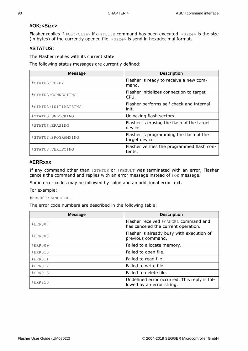
90 CHAPTER 4 ASCII command interface
#OK:<Size>
Flasher replies if #OK:<Size> if a #FSIZE command has been executed. <Size> is the size(in bytes) of the currently opened file. <Size> is send in hexadecimal format.
#STATUS:
The Flasher replies with its current state.
The following status messages are currently defined:
Message Description
#STATUS:READYFlasher is ready to receive a new com-mand.
#STATUS:CONNECTINGFlasher initializes connection to targetCPU.
#STATUS:INITIALIZINGFlasher performs self check and internalinit.
#STATUS:UNLOCKING Unlocking flash sectors.
#STATUS:ERASINGFlasher is erasing the flash of the targetdevice.
#STATUS:PROGRAMMINGFlasher is programming the flash of thetarget device.
#STATUS:VERIFYINGFlasher verifies the programmed flash con-tents.
#ERRxxx
If any command other than #STATUS or #RESULT was terminated with an error, Flashercancels the command and replies with an error message instead of #OK message.
Some error codes may be followed by colon and an additional error text.
For example:
#ERR007:CANCELED.
The error code numbers are described in the following table:
Message Description
#ERR007Flasher received #CANCEL command andhas canceled the current operation.
#ERR008Flasher is already busy with execution ofprevious command.
#ERR009 Failed to allocate memory.#ERR010 Failed to open file.#ERR011 Failed to read file.#ERR012 Failed to write file.#ERR013 Failed to delete file.
#ERR255Undefined error occurred. This reply is fol-lowed by an error string.
Flasher User Guide (UM08022) © 2004-2019 SEGGER Microcontroller GmbH
Chapter 5 Performance
The following chapter lists programming performance of common flash devices andmicro-controllers.
Flasher User Guide (UM08022) © 2004-2019 SEGGER Microcontroller GmbH
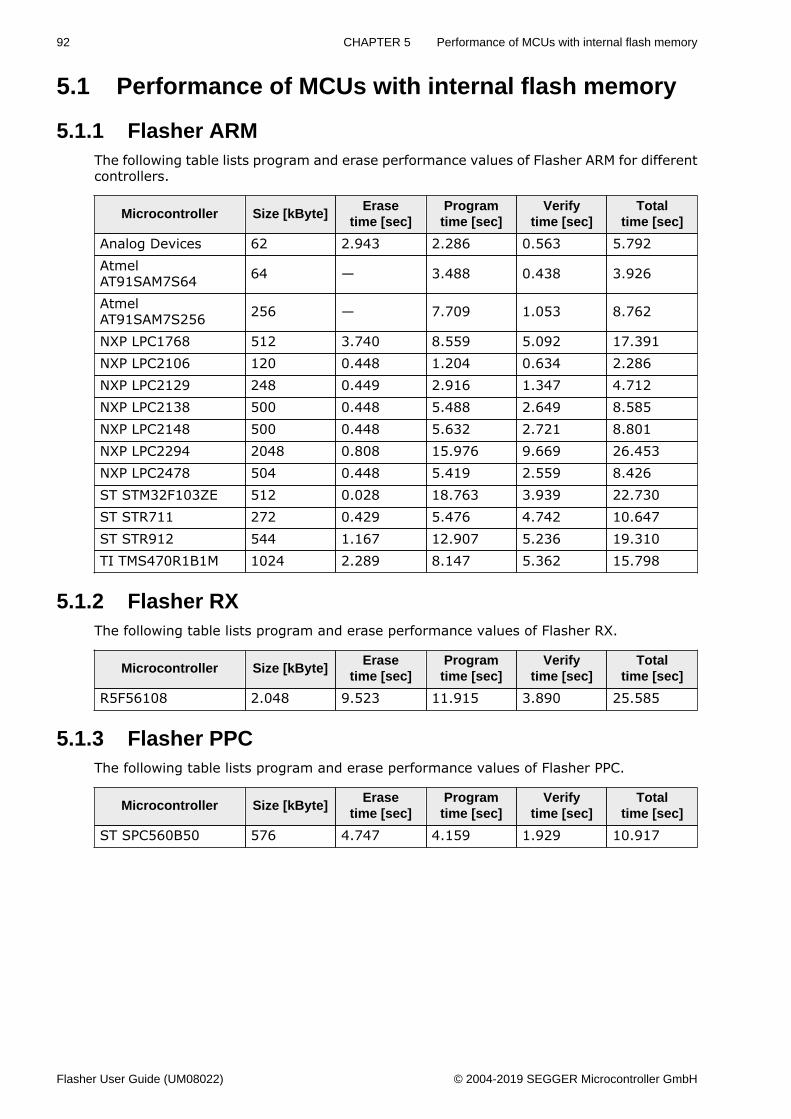
92 CHAPTER 5 Performance of MCUs with internal flash memory
5.1 Performance of MCUs with internal flash memory
5.1.1 Flasher ARMThe following table lists program and erase performance values of Flasher ARM for differentcontrollers.
Microcontroller Size [kByte]Erase
time [sec]Programtime [sec]
Verifytime [sec]
Totaltime [sec]
Analog Devices 62 2.943 2.286 0.563 5.792AtmelAT91SAM7S64 64 — 3.488 0.438 3.926
AtmelAT91SAM7S256 256 — 7.709 1.053 8.762
NXP LPC1768 512 3.740 8.559 5.092 17.391NXP LPC2106 120 0.448 1.204 0.634 2.286NXP LPC2129 248 0.449 2.916 1.347 4.712NXP LPC2138 500 0.448 5.488 2.649 8.585NXP LPC2148 500 0.448 5.632 2.721 8.801NXP LPC2294 2048 0.808 15.976 9.669 26.453NXP LPC2478 504 0.448 5.419 2.559 8.426ST STM32F103ZE 512 0.028 18.763 3.939 22.730ST STR711 272 0.429 5.476 4.742 10.647ST STR912 544 1.167 12.907 5.236 19.310TI TMS470R1B1M 1024 2.289 8.147 5.362 15.798
5.1.2 Flasher RXThe following table lists program and erase performance values of Flasher RX.
Microcontroller Size [kByte]Erase
time [sec]Programtime [sec]
Verifytime [sec]
Totaltime [sec]
R5F56108 2.048 9.523 11.915 3.890 25.585
5.1.3 Flasher PPCThe following table lists program and erase performance values of Flasher PPC.
Microcontroller Size [kByte]Erase
time [sec]Programtime [sec]
Verifytime [sec]
Totaltime [sec]
ST SPC560B50 576 4.747 4.159 1.929 10.917
Flasher User Guide (UM08022) © 2004-2019 SEGGER Microcontroller GmbH
Chapter 6 Hardware
This chapter gives an overview about Flasher specific hardware details, such as the pinoutsand available adapters.
Flasher User Guide (UM08022) © 2004-2019 SEGGER Microcontroller GmbH
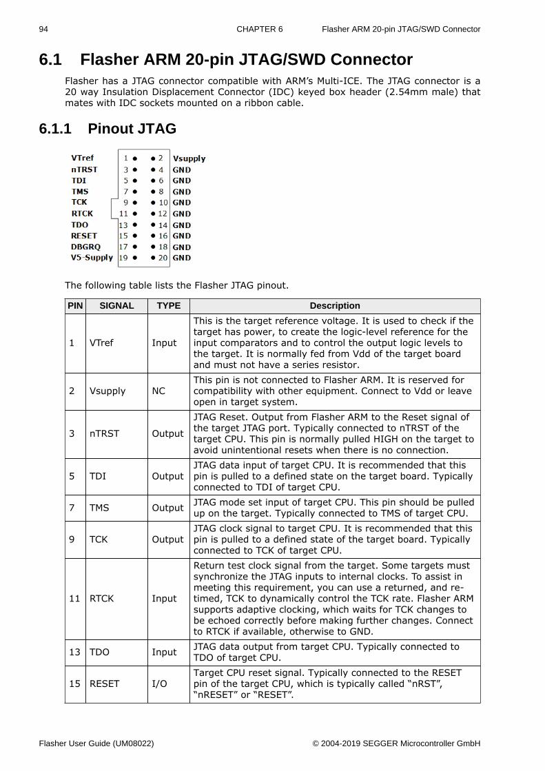
94 CHAPTER 6 Flasher ARM 20-pin JTAG/SWD Connector
6.1 Flasher ARM 20-pin JTAG/SWD ConnectorFlasher has a JTAG connector compatible with ARM’s Multi-ICE. The JTAG connector is a20 way Insulation Displacement Connector (IDC) keyed box header (2.54mm male) thatmates with IDC sockets mounted on a ribbon cable.
6.1.1 Pinout JTAG
The following table lists the Flasher JTAG pinout.
PIN SIGNAL TYPE Description
1 VTref Input
This is the target reference voltage. It is used to check if thetarget has power, to create the logic-level reference for theinput comparators and to control the output logic levels tothe target. It is normally fed from Vdd of the target boardand must not have a series resistor.
2 Vsupply NCThis pin is not connected to Flasher ARM. It is reserved forcompatibility with other equipment. Connect to Vdd or leaveopen in target system.
3 nTRST Output
JTAG Reset. Output from Flasher ARM to the Reset signal ofthe target JTAG port. Typically connected to nTRST of thetarget CPU. This pin is normally pulled HIGH on the target toavoid unintentional resets when there is no connection.
5 TDI OutputJTAG data input of target CPU. It is recommended that thispin is pulled to a defined state on the target board. Typicallyconnected to TDI of target CPU.
7 TMS Output JTAG mode set input of target CPU. This pin should be pulledup on the target. Typically connected to TMS of target CPU.
9 TCK OutputJTAG clock signal to target CPU. It is recommended that thispin is pulled to a defined state of the target board. Typicallyconnected to TCK of target CPU.
11 RTCK Input
Return test clock signal from the target. Some targets mustsynchronize the JTAG inputs to internal clocks. To assist inmeeting this requirement, you can use a returned, and re-timed, TCK to dynamically control the TCK rate. Flasher ARMsupports adaptive clocking, which waits for TCK changes tobe echoed correctly before making further changes. Connectto RTCK if available, otherwise to GND.
13 TDO Input JTAG data output from target CPU. Typically connected toTDO of target CPU.
15 RESET I/OTarget CPU reset signal. Typically connected to the RESETpin of the target CPU, which is typically called “nRST”,“nRESET” or “RESET”.
Flasher User Guide (UM08022) © 2004-2019 SEGGER Microcontroller GmbH
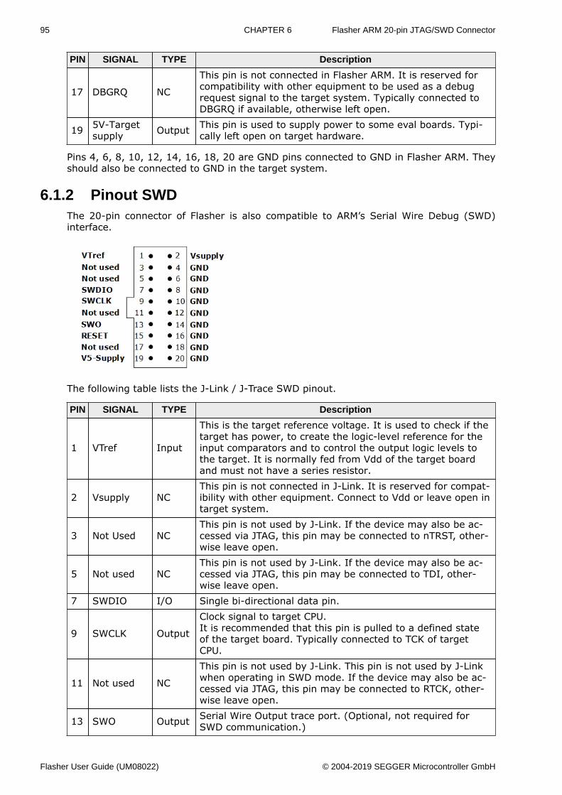
95 CHAPTER 6 Flasher ARM 20-pin JTAG/SWD Connector
PIN SIGNAL TYPE Description
17 DBGRQ NC
This pin is not connected in Flasher ARM. It is reserved forcompatibility with other equipment to be used as a debugrequest signal to the target system. Typically connected toDBGRQ if available, otherwise left open.
19 5V-Targetsupply Output This pin is used to supply power to some eval boards. Typi-
cally left open on target hardware.
Pins 4, 6, 8, 10, 12, 14, 16, 18, 20 are GND pins connected to GND in Flasher ARM. Theyshould also be connected to GND in the target system.
6.1.2 Pinout SWDThe 20-pin connector of Flasher is also compatible to ARM’s Serial Wire Debug (SWD)interface.
The following table lists the J-Link / J-Trace SWD pinout.
PIN SIGNAL TYPE Description
1 VTref Input
This is the target reference voltage. It is used to check if thetarget has power, to create the logic-level reference for theinput comparators and to control the output logic levels tothe target. It is normally fed from Vdd of the target boardand must not have a series resistor.
2 Vsupply NCThis pin is not connected in J-Link. It is reserved for compat-ibility with other equipment. Connect to Vdd or leave open intarget system.
3 Not Used NCThis pin is not used by J-Link. If the device may also be ac-cessed via JTAG, this pin may be connected to nTRST, other-wise leave open.
5 Not used NCThis pin is not used by J-Link. If the device may also be ac-cessed via JTAG, this pin may be connected to TDI, other-wise leave open.
7 SWDIO I/O Single bi-directional data pin.
9 SWCLK Output
Clock signal to target CPU.It is recommended that this pin is pulled to a defined stateof the target board. Typically connected to TCK of targetCPU.
11 Not used NC
This pin is not used by J-Link. This pin is not used by J-Linkwhen operating in SWD mode. If the device may also be ac-cessed via JTAG, this pin may be connected to RTCK, other-wise leave open.
13 SWO Output Serial Wire Output trace port. (Optional, not required forSWD communication.)
Flasher User Guide (UM08022) © 2004-2019 SEGGER Microcontroller GmbH
96 CHAPTER 6 Flasher ARM 20-pin JTAG/SWD Connector
PIN SIGNAL TYPE Description
15 RESET I/OTarget CPU reset signal. Typically connected to the RESETpin of the target CPU, which is typically called “nRST”,“nRESET” or “RESET”.
17 Not used NC This pin is not connected in J-Link.
19 5V-Targetsupply Output
This pin is used to supply power to some eval boards. Not allJ-Links supply power on this pin, only the KS (Kickstart) ver-sions. Typically left open on target hardware.
Pins 4, 6, 8, 10, 12, 14, 16, 18, 20 are GND pins connected to GND in J-Link. They shouldalso be connected to GND in the target system.
6.1.3 Target power supplyPin 19 of the connector can be used to supply power to the target hardware. Supply volt-age is 5V, max. current is 400mA. The output current is monitored and protected againstoverload and short-circuit.
Power can be controlled via the J-Link commander. The following commands are availableto control power:
Command Explanation
power on Switch target power onpower off Switch target power offpower on perm Set target power supply default to “on”power off perm Set target power supply default to “off”
Flasher User Guide (UM08022) © 2004-2019 SEGGER Microcontroller GmbH
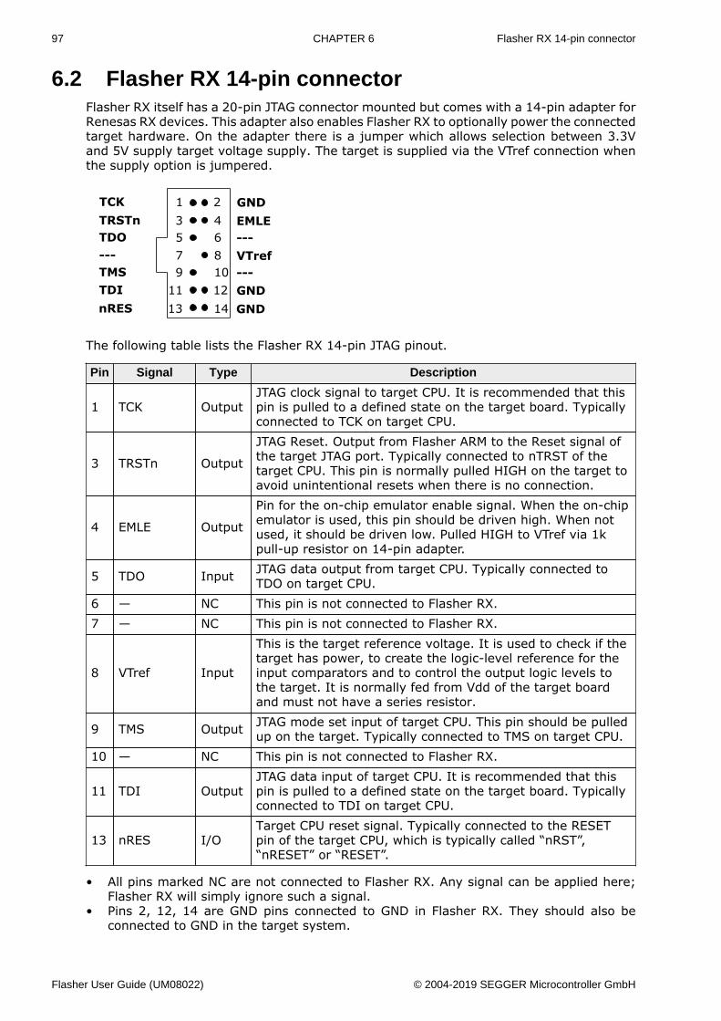
97 CHAPTER 6 Flasher RX 14-pin connector
6.2 Flasher RX 14-pin connectorFlasher RX itself has a 20-pin JTAG connector mounted but comes with a 14-pin adapter forRenesas RX devices. This adapter also enables Flasher RX to optionally power the connectedtarget hardware. On the adapter there is a jumper which allows selection between 3.3Vand 5V supply target voltage supply. The target is supplied via the VTref connection whenthe supply option is jumpered.
The following table lists the Flasher RX 14-pin JTAG pinout.
Pin Signal Type Description
1 TCK OutputJTAG clock signal to target CPU. It is recommended that thispin is pulled to a defined state on the target board. Typicallyconnected to TCK on target CPU.
3 TRSTn Output
JTAG Reset. Output from Flasher ARM to the Reset signal ofthe target JTAG port. Typically connected to nTRST of thetarget CPU. This pin is normally pulled HIGH on the target toavoid unintentional resets when there is no connection.
4 EMLE Output
Pin for the on-chip emulator enable signal. When the on-chipemulator is used, this pin should be driven high. When notused, it should be driven low. Pulled HIGH to VTref via 1kpull-up resistor on 14-pin adapter.
5 TDO Input JTAG data output from target CPU. Typically connected toTDO on target CPU.
6 — NC This pin is not connected to Flasher RX.7 — NC This pin is not connected to Flasher RX.
8 VTref Input
This is the target reference voltage. It is used to check if thetarget has power, to create the logic-level reference for theinput comparators and to control the output logic levels tothe target. It is normally fed from Vdd of the target boardand must not have a series resistor.
9 TMS Output JTAG mode set input of target CPU. This pin should be pulledup on the target. Typically connected to TMS on target CPU.
10 — NC This pin is not connected to Flasher RX.
11 TDI OutputJTAG data input of target CPU. It is recommended that thispin is pulled to a defined state on the target board. Typicallyconnected to TDI on target CPU.
13 nRES I/OTarget CPU reset signal. Typically connected to the RESETpin of the target CPU, which is typically called “nRST”,“nRESET” or “RESET”.
• All pins marked NC are not connected to Flasher RX. Any signal can be applied here;Flasher RX will simply ignore such a signal.
• Pins 2, 12, 14 are GND pins connected to GND in Flasher RX. They should also beconnected to GND in the target system.
Flasher User Guide (UM08022) © 2004-2019 SEGGER Microcontroller GmbH
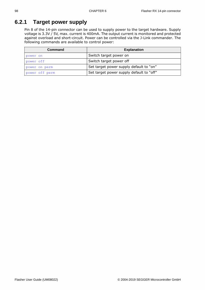
98 CHAPTER 6 Flasher RX 14-pin connector
6.2.1 Target power supplyPin 8 of the 14-pin connector can be used to supply power to the target hardware. Supplyvoltage is 3.3V / 5V, max. current is 400mA. The output current is monitored and protectedagainst overload and short-circuit. Power can be controlled via the J-Link commander. Thefollowing commands are available to control power:
Command Explanation
power on Switch target power onpower off Switch target power offpower on perm Set target power supply default to “on”power off perm Set target power supply default to “off”
Flasher User Guide (UM08022) © 2004-2019 SEGGER Microcontroller GmbH
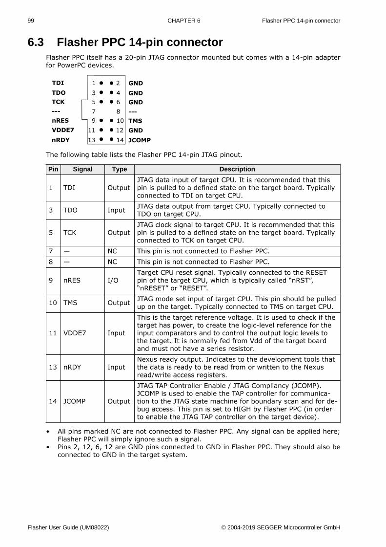
99 CHAPTER 6 Flasher PPC 14-pin connector
6.3 Flasher PPC 14-pin connectorFlasher PPC itself has a 20-pin JTAG connector mounted but comes with a 14-pin adapterfor PowerPC devices.
The following table lists the Flasher PPC 14-pin JTAG pinout.
Pin Signal Type Description
1 TDI OutputJTAG data input of target CPU. It is recommended that thispin is pulled to a defined state on the target board. Typicallyconnected to TDI on target CPU.
3 TDO Input JTAG data output from target CPU. Typically connected toTDO on target CPU.
5 TCK OutputJTAG clock signal to target CPU. It is recommended that thispin is pulled to a defined state on the target board. Typicallyconnected to TCK on target CPU.
7 — NC This pin is not connected to Flasher PPC.8 — NC This pin is not connected to Flasher PPC.
9 nRES I/OTarget CPU reset signal. Typically connected to the RESETpin of the target CPU, which is typically called “nRST”,“nRESET” or “RESET”.
10 TMS Output JTAG mode set input of target CPU. This pin should be pulledup on the target. Typically connected to TMS on target CPU.
11 VDDE7 Input
This is the target reference voltage. It is used to check if thetarget has power, to create the logic-level reference for theinput comparators and to control the output logic levels tothe target. It is normally fed from Vdd of the target boardand must not have a series resistor.
13 nRDY InputNexus ready output. Indicates to the development tools thatthe data is ready to be read from or written to the Nexusread/write access registers.
14 JCOMP Output
JTAG TAP Controller Enable / JTAG Compliancy (JCOMP).JCOMP is used to enable the TAP controller for communica-tion to the JTAG state machine for boundary scan and for de-bug access. This pin is set to HIGH by Flasher PPC (in orderto enable the JTAG TAP controller on the target device).
• All pins marked NC are not connected to Flasher PPC. Any signal can be applied here;Flasher PPC will simply ignore such a signal.
• Pins 2, 12, 6, 12 are GND pins connected to GND in Flasher PPC. They should also beconnected to GND in the target system.
Flasher User Guide (UM08022) © 2004-2019 SEGGER Microcontroller GmbH
100 CHAPTER 6 Target board design
6.4 Target board designWe strongly advise following the recommendations given by the chip manufacturer. Theserecommendations are normally in line with the recommendations. Please refer to the theappropriate tables depending on the core:• Pinout JTAG on page 94• Pinout SWD on page 95• Flasher RX 14-pin connector on page 97• Flasher PPC 14-pin connector on page 99
In case of doubt you should follow the recommendations given by the semiconductor man-ufacturer.
6.4.1 Pull-up/pull-down resistorsUnless otherwise specified by developer’s manual, pull-ups/pull-downs are recommendedto be between 2.2 kOhms and 47 kOhms.
6.4.2 RESET, nTRSTThe debug logic is reset independently from the CPU core with nTRST. For the core tooperate correctly it is essential that both signals are asserted after power-up.
The advantage of having separate connection to the two reset signals is that it allows thedeveloper performing software debug to setup breakpoints, which are retained by the debuglogic even when the core is reset. (For example, at the reset vector address, to allow thecode to be single-stepped as soon as it comes out of reset). This can be particularly usefulwhen first trying to bring up a board with a new ASIC.
Flasher User Guide (UM08022) © 2004-2019 SEGGER Microcontroller GmbH
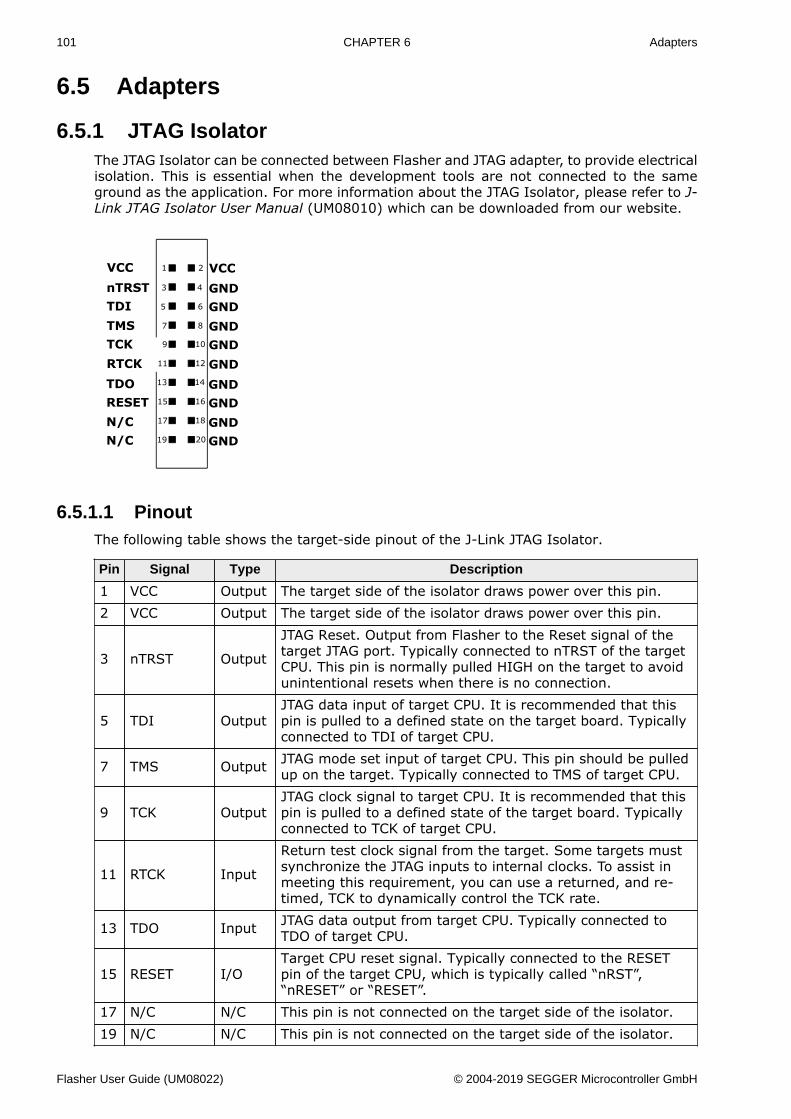
101 CHAPTER 6 Adapters
6.5 Adapters
6.5.1 JTAG IsolatorThe JTAG Isolator can be connected between Flasher and JTAG adapter, to provide electricalisolation. This is essential when the development tools are not connected to the sameground as the application. For more information about the JTAG Isolator, please refer to J-Link JTAG Isolator User Manual (UM08010) which can be downloaded from our website.
6.5.1.1 PinoutThe following table shows the target-side pinout of the J-Link JTAG Isolator.
Pin Signal Type Description
1 VCC Output The target side of the isolator draws power over this pin.2 VCC Output The target side of the isolator draws power over this pin.
3 nTRST Output
JTAG Reset. Output from Flasher to the Reset signal of thetarget JTAG port. Typically connected to nTRST of the targetCPU. This pin is normally pulled HIGH on the target to avoidunintentional resets when there is no connection.
5 TDI OutputJTAG data input of target CPU. It is recommended that thispin is pulled to a defined state on the target board. Typicallyconnected to TDI of target CPU.
7 TMS Output JTAG mode set input of target CPU. This pin should be pulledup on the target. Typically connected to TMS of target CPU.
9 TCK OutputJTAG clock signal to target CPU. It is recommended that thispin is pulled to a defined state of the target board. Typicallyconnected to TCK of target CPU.
11 RTCK Input
Return test clock signal from the target. Some targets mustsynchronize the JTAG inputs to internal clocks. To assist inmeeting this requirement, you can use a returned, and re-timed, TCK to dynamically control the TCK rate.
13 TDO Input JTAG data output from target CPU. Typically connected toTDO of target CPU.
15 RESET I/OTarget CPU reset signal. Typically connected to the RESETpin of the target CPU, which is typically called “nRST”,“nRESET” or “RESET”.
17 N/C N/C This pin is not connected on the target side of the isolator.19 N/C N/C This pin is not connected on the target side of the isolator.
Flasher User Guide (UM08022) © 2004-2019 SEGGER Microcontroller GmbH
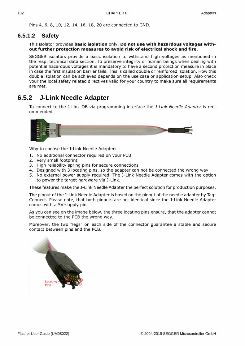
102 CHAPTER 6 Adapters
Pins 4, 6, 8, 10, 12, 14, 16, 18, 20 are connected to GND.
6.5.1.2 SafetyThis isolator provides basic isolation only. Do not use with hazardous voltages with-out further protection measures to avoid risk of electrical shock and fire.
SEGGER isolators provide a basic isolation to withstand high voltages as mentioned inthe resp. technical data section. To preserve integrity of human beings when dealing withpotential hazardous voltages it is mandatory to have a second protection measure in placein case the first insulation barrier fails. This is called double or reinforced isolation. How thisdouble isolation can be achieved depends on the use case or application setup. Also checkyour the local safety related directives valid for your country to make sure all requirementsare met.
6.5.2 J-Link Needle AdapterTo connect to the J-Link OB via programming interface the J-Link Needle Adapter is rec-ommended.
Why to choose the J-Link Needle Adapter:1. No additional connector required on your PCB2. Very small footprint3. High reliability spring pins for secure connections4. Designed with 3 locating pins, so the adapter can not be connected the wrong way5. No external power supply required! The J-Link Needle Adapter comes with the option
to power the target hardware via J-Link.
These features make the J-Link Needle Adapter the perfect solution for production purposes.
The pinout of the J-Link Needle Adapter is based on the pinout of the needle adapter by Tag-Connect. Please note, that both pinouts are not identical since the J-Link Needle Adaptercomes with a 5V-supply pin.
As you can see on the image below, the three locating pins ensure, that the adapter cannotbe connected to the PCB the wrong way.
Moreover, the two “legs” on each side of the connector guarantee a stable and securecontact between pins and the PCB.
Flasher User Guide (UM08022) © 2004-2019 SEGGER Microcontroller GmbH
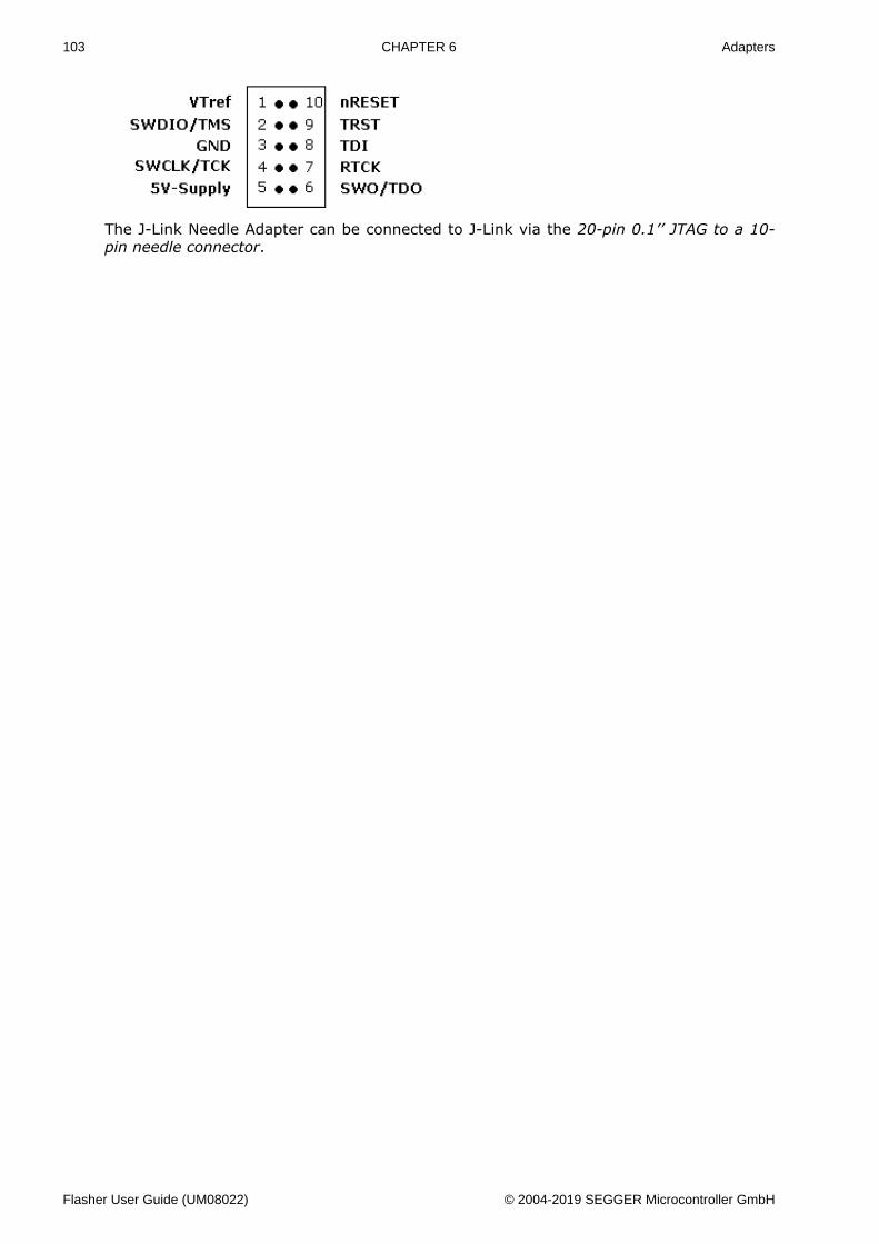
103 CHAPTER 6 Adapters
The J-Link Needle Adapter can be connected to J-Link via the 20-pin 0.1’’ JTAG to a 10-pin needle connector.
Flasher User Guide (UM08022) © 2004-2019 SEGGER Microcontroller GmbH
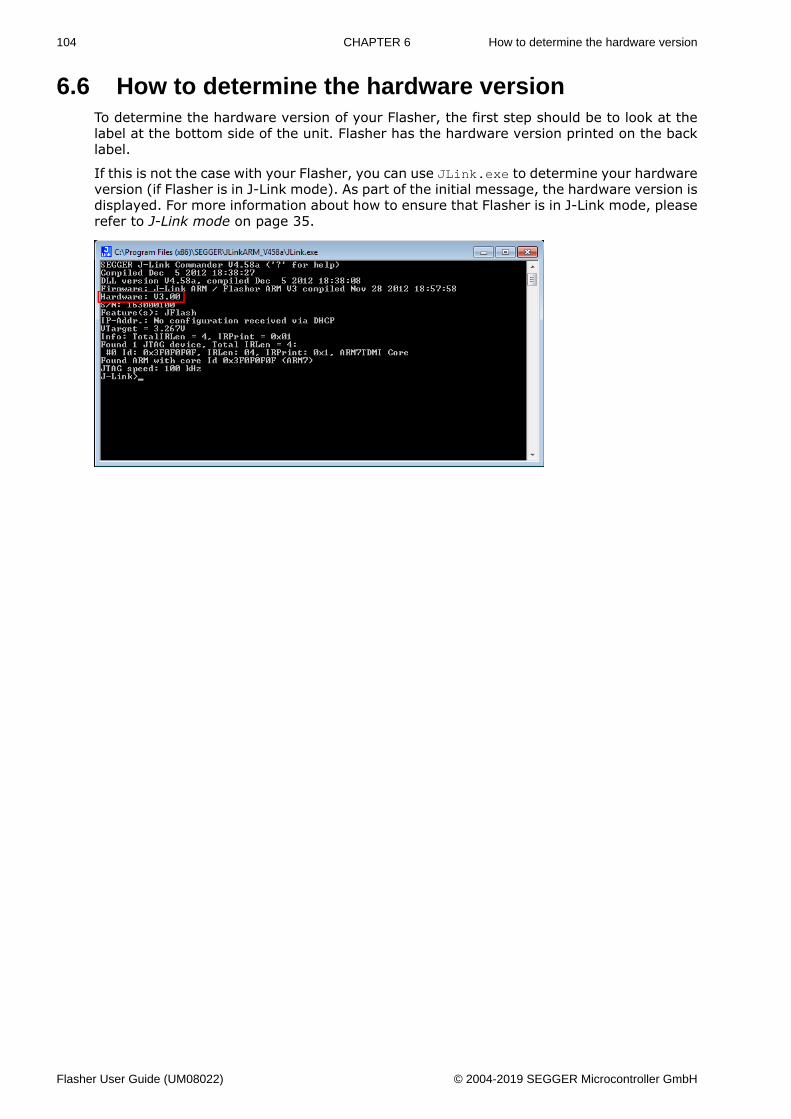
104 CHAPTER 6 How to determine the hardware version
6.6 How to determine the hardware versionTo determine the hardware version of your Flasher, the first step should be to look at thelabel at the bottom side of the unit. Flasher has the hardware version printed on the backlabel.
If this is not the case with your Flasher, you can use JLink.exe to determine your hardwareversion (if Flasher is in J-Link mode). As part of the initial message, the hardware version isdisplayed. For more information about how to ensure that Flasher is in J-Link mode, pleaserefer to J-Link mode on page 35.
Flasher User Guide (UM08022) © 2004-2019 SEGGER Microcontroller GmbH
Chapter 7 Support and FAQs
This chapter contains troubleshooting tips together with solutions for common problemswhich might occur when using Flasher. There are several steps you can take before con-tacting support. Performing these steps can solve many problems and often eliminates theneed for assistance. This chapter also contains a collection of frequently asked questions(FAQs) with answers.
Flasher User Guide (UM08022) © 2004-2019 SEGGER Microcontroller GmbH
106 CHAPTER 7 Contacting support
7.1 Contacting supportBefore contacting support, make sure you tried to solve your problem by trying your Flasherwith another PC and if possible with another target system to see if it works there. If thedevice functions correctly, the USB setup on the original machine or your target hardwareis the source of the problem, not Flasher.
If you need to contact support, send the following information [email protected]• A detailed description of the problem• Flasher serial number• Information about your target hardware (processor, board, etc.).• FLASHER.CFG, FLASHER.DAT, FLASHER.LOG, SERIAL.TXT file from Flasher. To get these
files, Flasher has to be in MSD mode. For more information about how to boot Flasherin MSD mode, please refer to MSD mode on page 38.
Flasher is sold directly by SEGGER.
Flasher User Guide (UM08022) © 2004-2019 SEGGER Microcontroller GmbH
107 CHAPTER 7 Frequently Asked Questions
7.2 Frequently Asked QuestionsMaximum JTAG speedQ: What is the maximum JTAG speed supported by Flasher?A: Flasher’s maximum supported JTAG speed is 12MHz.
Maximum download speedQ: What is the maximum download speed?A: The maximum download speed is currently about 720 Kbytes/second when downloading
into RAM. The actual speed depends on various factors, such as JTAG, clock speed, hostCPU core etc.
Flasher User Guide (UM08022) © 2004-2019 SEGGER Microcontroller GmbH
Chapter 8 Background information
This chapter provides background information about flash programming in general. It alsoprovides information about how to replace the firmware of Flasher manually.
Flasher User Guide (UM08022) © 2004-2019 SEGGER Microcontroller GmbH
109 CHAPTER 8 Flash programming
8.1 Flash programmingFlasher comes with a DLL, which allows - amongst other functionalities - reading and writingRAM, CPU registers, starting and stopping the CPU, and setting breakpoints.
8.1.1 How does flash programming via Flasher work?This requires extra code. This extra code typically downloads a program into the RAM ofthe target system, which is able to erase and program the flash. This program is calledRAM code and “knows” how to program the flash; it contains an implementation of theflash programming algorithm for the particular flash. Different flash chips have differentprogramming algorithms;the programming algorithm also depends on other things, suchas endianess of the target system and organization of the flash memory (for example 1 *8 bits, 1 * 16 bits, 2 * 16 bits or 32 bits). The RAM code requires data to be programmedinto the flash memory. The data is supplied by downloading it to RAM.
8.1.2 Data download to RAMThe data (or part of it) is downloaded to another part of the RAM of the target system. TheInstruction pointer (PC) of the CPU is then set to the start address of the Ram code, theCPU is started, executing the RAM code. The RAM code, which contains the programmingalgorithm for the flash chip, copies the data into the flash chip. The CPU is stopped after this.This process may have to be repeated until the entire data is programmed into the flash.
8.1.3 Available options for flash programmingIn general, there are two possibilities in order to use Flasher for flash programming:• Using Flasher stand-alone to program the target flash memory (stand-alone mode)• Using Flasher in combination with J-Flash to program the target flash memory (Flasher
in “J-Link mode”)
8.1.3.1 Using Flasher in stand-alone modeIn order to use the Flasher in stand-alone mode, it has to be configured first. For moreinformation about how to setup Flasher for using in “stand-alone mode”, please refer toSetting up Flasher for stand-alone mode on page 39.
8.1.3.2 J-Flash - Complete flash programming solutionJ-Flash is a stand-alone Windows application, which can read / write data files and programthe flash in almost any ARM system. For more information about J-Flash please refer to theJ-Flash User Guide, which can be downloaded from our website http://www.segger.com.
8.1.4 How does the universal flash programming work?In universal flash programming mode, the flasher typically communicates with a boot loaderrunning on the device using a vendor specific protocol, rather than using the debug inter-face.
Universal flash programming is available only for stand-alone mode.
Flasher User Guide (UM08022) © 2004-2019 SEGGER Microcontroller GmbH
Chapter 9 Glossary
This chapter describes important terms used throughout this manual.
Flasher User Guide (UM08022) © 2004-2019 SEGGER Microcontroller GmbH
111 CHAPTER 9
Big-endian
Memory organization where the least significant byte of a word is at a higher address thanthe most significant byte. See Little-endian.
Cache cleaning
The process of writing dirty data in a cache to main memory.
Coprocessor
An additional processor that is used for certain operations, for example, for floating-pointmath calculations, signal processing, or memory management.
Dirty data
When referring to a processor data cache, data that has been written to the cache buthas not been written to main memory is referred to as dirty data. Only write-back cachescan have dirty data because a write-through cache writes data to the cache and to mainmemory simultaneously. See also cache cleaning.
Halfword
A 16-bit unit of information.
Host
A computer which provides data and other services to another computer. Especially, acomputer providing debugging services to a target being debugged.
ICache
Instruction cache.
ID
Identifier.
IEEE 1149.1
The IEEE Standard which defines TAP. Commonly (but incorrectly) referred to as JTAG.
Image
An executable file that has been loaded onto a processor for execution.
Instruction Register
When referring to a TAP controller, a register that controls the operation of the TAP.
IR
See Instruction Register.
Joint Test Action Group (JTAG)
The name of the standards group which created the IEEE 1149.1 specification.
Little-endian
Memory organization where the least significant byte of a word is at a lower address thanthe most significant byte. See also Big-endian.
Memory coherency
A memory is coherent if the value read by a data read or instruction fetch is the value thatwas most recently written to that location. Obtaining memory coherency is difficult when
Flasher User Guide (UM08022) © 2004-2019 SEGGER Microcontroller GmbH
112 CHAPTER 9
there are multiple possible physical locations that are involved, such as a system that hasmain memory, a write buffer, and a cache.
Memory management unit (MMU)
Hardware that controls caches and access permissions to blocks of memory, and translatesvirtual to physical addresses.
Memory Protection Unit (MPU)
Hardware that controls access permissions to blocks of memory. Unlike an MMU, a MPUdoes not translate virtual addresses to physical addresses.
RESET
Abbreviation of System Reset. The electronic signal which causes the target system otherthan the TAP controller to be reset. This signal is also known as “nSRST” “nSYSRST”, “nRST”,or “nRESET” in some other manuals. See also nTRST.
nTRST
Abbreviation of TAP Reset. The electronic signal that causes the target system TAP controllerto be reset. This signal is known as nICERST in some other manuals. See also nSRST.
Open collector
A signal that may be actively driven LOW by one or more drivers, and is otherwise passivelypulled HIGH. Also known as a “wired AND” signal.
Processor Core
The part of a microprocessor that reads instructions from memory and executes them,including the instruction fetch unit, arithmetic and logic unit, and the register bank. Itexcludes optional coprocessors, caches, and the memory management unit.
Remapping
Changing the address of physical memory or devices after the application has started ex-ecuting. This is typically done to make RAM replace ROM once the initialization has beendone.
RTOS
Real Time Operating System.
TAP Controller
Logic on a device which allows access to some or all of that device for test purposes. Thecircuit functionality is defined in IEEE1149.1.
Target
The actual processor (real silicon or simulated) on which the application program is running.
TCK
The electronic clock signal which times data on the TAP data lines TMS, TDI, and TDO.
TDI
The electronic signal input to a TAP controller from the data source (upstream). Usually,this is seen connecting the J-Link Interface Unit to the first TAP controller.
TDO
The electronic signal output from a TAP controller to the data sink (downstream). Usually,this is seen connecting the last TAP controller to the J-Link Interface Unit.
Flasher User Guide (UM08022) © 2004-2019 SEGGER Microcontroller GmbH
113 CHAPTER 9
Test Access Port (TAP)
The port used to access a device’s TAP Controller. Comprises TCK, TMS, TDI, TDO, andnTRST (optional).
Transistor-transistor logic (TTL)
A type of logic design in which two bipolar transistors drive the logic output to one orzero. LSI and VLSI logic often used TTL with HIGH logic level approaching +5V and LOWapproaching 0V.
Word
A 32-bit unit of information. Contents are taken as being an unsigned integer unless oth-erwise stated.
Flasher User Guide (UM08022) © 2004-2019 SEGGER Microcontroller GmbH
Chapter 10 Literature and references
This chapter lists documents, which we think may be useful to gain a deeper under- standingof technical details.
Flasher User Guide (UM08022) © 2004-2019 SEGGER Microcontroller GmbH
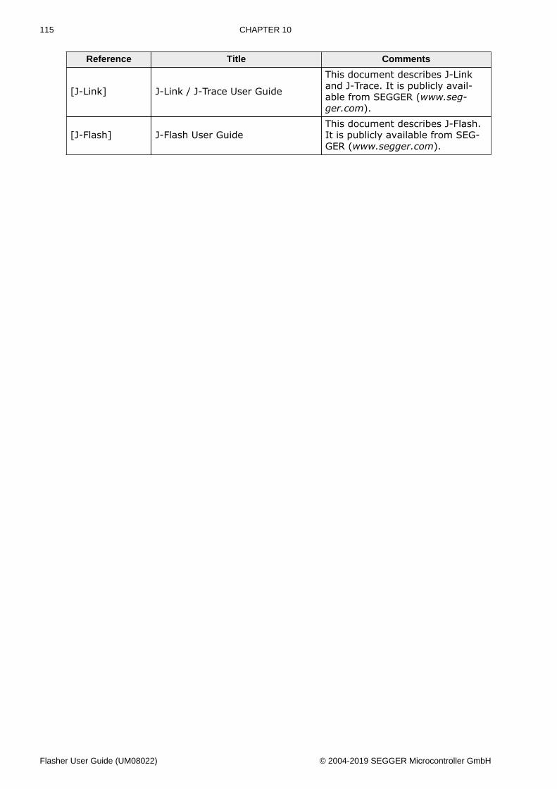
115 CHAPTER 10
Reference Title Comments
[J-Link] J-Link / J-Trace User Guide
This document describes J-Linkand J-Trace. It is publicly avail-able from SEGGER (www.seg-ger.com).
[J-Flash] J-Flash User GuideThis document describes J-Flash.It is publicly available from SEG-GER (www.segger.com).
Flasher User Guide (UM08022) © 2004-2019 SEGGER Microcontroller GmbH