Embed Size (px)
Citation preview
Fluids, Thermodynamics, Waves, & OpticsOpticsLab 7
Reflection & Refraction
Lana Sheridan
De Anza College
May 30, 2018
Overview
• Purpose
• Laser safety
• Part 1: Reflection
• Part 2: Refraction
• Part 3: Total internal reflection
Purpose of the Lab
To explore basic ray optics including the reflection and refractionof beams of light.
You will use a laser beam on an optical bench and a device formeasuring angles to investigate different ray optics situations.
You will
1 measure incidence and reflection angles to confirm the law ofreflection.
2 measure a transparent block’s thickness, incidence angles andbeam displacement distances to find the block’s index ofrefraction.
3 use the idea of total internal reflection to find the index ofrefraction of a transparent triangular prism.
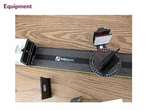
Equipment
Laser Safety!
Laser Safety!
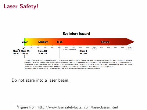
Do not stare into a laser beam.
1Figure from http://www.lasersafetyfacts. com/laserclasses.html
Laser Safety!
It is easy to use a laser to damage your eyes.
It is also easy to stay safe.
Simple rule: never move your head through the plane of theoptical bench with the laser beam on and the shutter open.
For example, you drop your pen. Just close the shutter all the way(labelled “attenuator”) before you bend over to pick it up.
Since the lab has many groups, also close your eyes as you moveyour head through the plane of the benches. As much as possibletry to keep your head above bench level.
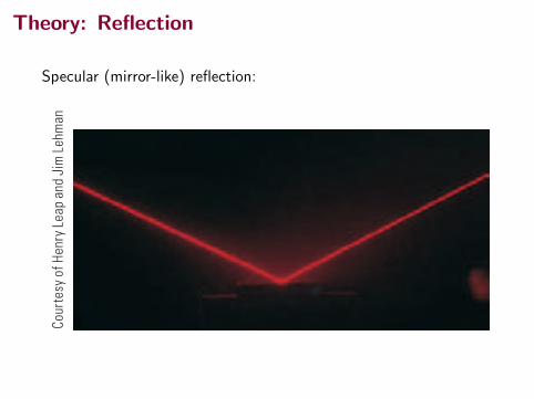
Theory: Reflection
Specular (mirror-like) reflection:
1062 Chapter 35 The Nature of Light and the Principles of Ray Optics
is reflected. For waves on a one-dimensional string, the reflected wave must neces-sarily be restricted to a direction along the string. For light waves traveling in three- dimensional space, no such restriction applies and the reflected light waves can be in directions different from the direction of the incident waves. Figure 35.5a shows sev-eral rays of a beam of light incident on a smooth, mirror-like, reflecting surface. The reflected rays are parallel to one another as indicated in the figure. The direction of a reflected ray is in the plane perpendicular to the reflecting surface that contains the incident ray. Reflection of light from such a smooth surface is called specular reflection. If the reflecting surface is rough as in Figure 35.5b, the surface reflects the rays not as a parallel set but in various directions. Reflection from any rough surface is known as diffuse reflection. A surface behaves as a smooth surface as long as the surface variations are much smaller than the wavelength of the incident light. The difference between these two kinds of reflection explains why it is more dif-ficult to see while driving on a rainy night than on a dry night. If the road is wet, the smooth surface of the water specularly reflects most of your headlight beams away from your car (and perhaps into the eyes of oncoming drivers). When the road is dry, its rough surface diffusely reflects part of your headlight beam back toward you, allowing you to see the road more clearly. Your bathroom mirror exhib-its specular reflection, whereas light reflecting from this page experiences diffuse reflection. In this book, we restrict our study to specular reflection and use the term reflection to mean specular reflection. Consider a light ray traveling in air and incident at an angle on a flat, smooth surface as shown in Figure 35.6. The incident and reflected rays make angles u1 and u91, respectively, where the angles are measured between the normal and the rays. (The normal is a line drawn perpendicular to the surface at the point where the incident ray strikes the surface.) Experiments and theory show that the angle of reflection equals the angle of incidence:
u91 5 u1 (35.2)
This relationship is called the law of reflection. Because reflection of waves from an interface between two media is a common phenomenon, we identify an analysis model for this situation: the wave under reflection. Equation 35.2 is the mathemat-ical representation of this model.
Q uick Quiz 35.1 In the movies, you sometimes see an actor looking in a mirror and you can see his face in the mirror. It can be said with certainty that during the filming of such a scene, the actor sees in the mirror: (a) his face (b) your face (c) the director’s face (d) the movie camera (e) impossible to determine
Law of reflection X
a b
c
Cour
tesy
of H
enry
Lea
p an
d Ji
m L
ehm
an
d
Cour
tesy
of H
enry
Lea
p an
d Ji
m L
ehm
an
Figure 35.5 Schematic repre-sentation of (a) specular reflec-tion, where the reflected rays are all parallel to one another, and (b) diffuse reflection, where the reflected rays travel in random directions. (c) and (d) Photo-graphs of specular and diffuse reflection using laser light.
u1
Incidentray
Normal
Reflectedray
The incident ray, the reflected ray, and the normal all lie in the same plane, and u! " u1.1
u!1
Figure 35.6 The wave under reflection model.
Pitfall Prevention 35.1Subscript Notation The subscript 1 refers to parameters for the light in the initial medium. When light travels from one medium to another, we use the subscript 2 for the parameters associated with the light in the new medium. In this discussion, the light stays in the same medium, so we only have to use the subscript 1.
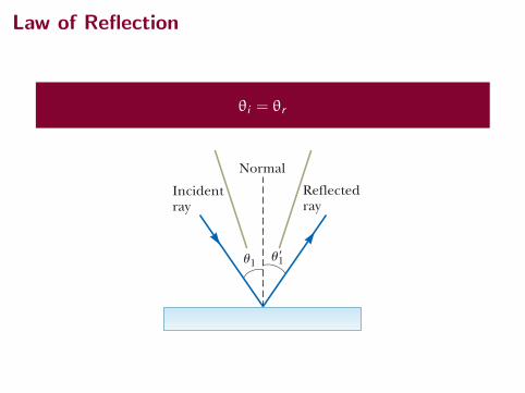
Law of Reflection
θi = θr
1062 Chapter 35 The Nature of Light and the Principles of Ray Optics
is reflected. For waves on a one-dimensional string, the reflected wave must neces-sarily be restricted to a direction along the string. For light waves traveling in three- dimensional space, no such restriction applies and the reflected light waves can be in directions different from the direction of the incident waves. Figure 35.5a shows sev-eral rays of a beam of light incident on a smooth, mirror-like, reflecting surface. The reflected rays are parallel to one another as indicated in the figure. The direction of a reflected ray is in the plane perpendicular to the reflecting surface that contains the incident ray. Reflection of light from such a smooth surface is called specular reflection. If the reflecting surface is rough as in Figure 35.5b, the surface reflects the rays not as a parallel set but in various directions. Reflection from any rough surface is known as diffuse reflection. A surface behaves as a smooth surface as long as the surface variations are much smaller than the wavelength of the incident light. The difference between these two kinds of reflection explains why it is more dif-ficult to see while driving on a rainy night than on a dry night. If the road is wet, the smooth surface of the water specularly reflects most of your headlight beams away from your car (and perhaps into the eyes of oncoming drivers). When the road is dry, its rough surface diffusely reflects part of your headlight beam back toward you, allowing you to see the road more clearly. Your bathroom mirror exhib-its specular reflection, whereas light reflecting from this page experiences diffuse reflection. In this book, we restrict our study to specular reflection and use the term reflection to mean specular reflection. Consider a light ray traveling in air and incident at an angle on a flat, smooth surface as shown in Figure 35.6. The incident and reflected rays make angles u1 and u91, respectively, where the angles are measured between the normal and the rays. (The normal is a line drawn perpendicular to the surface at the point where the incident ray strikes the surface.) Experiments and theory show that the angle of reflection equals the angle of incidence:
u91 5 u1 (35.2)
This relationship is called the law of reflection. Because reflection of waves from an interface between two media is a common phenomenon, we identify an analysis model for this situation: the wave under reflection. Equation 35.2 is the mathemat-ical representation of this model.
Q uick Quiz 35.1 In the movies, you sometimes see an actor looking in a mirror and you can see his face in the mirror. It can be said with certainty that during the filming of such a scene, the actor sees in the mirror: (a) his face (b) your face (c) the director’s face (d) the movie camera (e) impossible to determine
Law of reflection X
a b
c
Cour
tesy
of H
enry
Lea
p an
d Ji
m L
ehm
an
d
Cour
tesy
of H
enry
Lea
p an
d Ji
m L
ehm
an
Figure 35.5 Schematic repre-sentation of (a) specular reflec-tion, where the reflected rays are all parallel to one another, and (b) diffuse reflection, where the reflected rays travel in random directions. (c) and (d) Photo-graphs of specular and diffuse reflection using laser light.
u1
Incidentray
Normal
Reflectedray
The incident ray, the reflected ray, and the normal all lie in the same plane, and u! " u1.1
u!1
Figure 35.6 The wave under reflection model.
Pitfall Prevention 35.1Subscript Notation The subscript 1 refers to parameters for the light in the initial medium. When light travels from one medium to another, we use the subscript 2 for the parameters associated with the light in the new medium. In this discussion, the light stays in the same medium, so we only have to use the subscript 1.
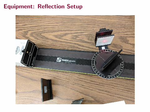
Equipment: Reflection Setup
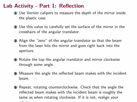
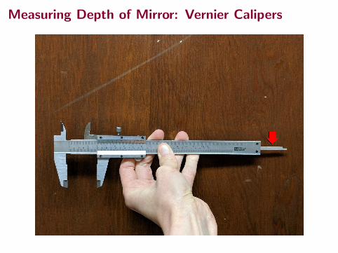
Lab Activity - Part 1: Reflection1 Use Vernier calipers to measure the depth of the mirror inside
the plastic case.
2 Use this value to carefully set the surface of the mirror in thecrosshairs of the angular translator.
3 Align the “zero” of the angular translator so that the beamfrom the laser hits the mirror and goes right back into theaperture.
4 Rotate the top the angular translator and mirror clockwisethrough some angle.
5 Measure the angle the reflected beam makes with the incidentbeam.
6 Repeat, rotating counterclockwise. Check that the angle thereflected beam makes with the incident beam is roughly thesame as when rotating clockwise. If it is not, realign yourmirror.
Measuring Depth of Mirror: Vernier Calipers
Measuring Depth of Mirror
Lab Activity - Part 1: Reflection
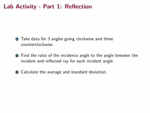
7 Take data for 3 angles going clockwise and threecounterclockwise.
8 Find the ratio of the incidence angle to the angle between theincident and reflected ray for each incident angle.
9 Calculate the average and standard deviation.
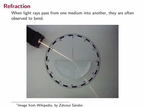
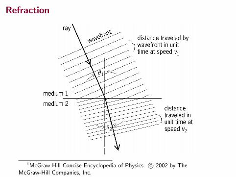
RefractionWhen light rays pass from one medium into another, they are oftenobserved to bend.
1Image from Wikipedia, by Zatonyi Sandor.
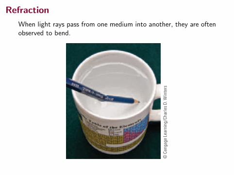
Refraction
When light rays pass from one medium into another, they are oftenobserved to bend.
Conceptual Questions 1079
5. Retroreflection by transparent spheres, mentioned in Section 35.4, can be observed with dewdrops. To do so, look at your head’s shadow where it falls on dewy grass. The optical display around the shadow of your head is called heiligen schein, which is German for holy light. Renaissance artist Benvenuto Cellini described the phenomenon and his reaction in his Autobiography, at the end of Part One, and American philosopher Henry David Thoreau did the same in Walden, “Baker Farm,” second paragraph. Do some Internet research to find out more about the heiligenschein.
6. Sound waves have much in common with light waves, including the properties of reflection and refraction. Give an example of each of these phenomena for sound waves.
7. Total internal reflection is applied in the periscope of a submerged submarine to let the user observe events above the water surface. In this device, two prisms are arranged as shown in Figure CQ35.7 so that an incident beam of light follows the path shown. Parallel tilted, silvered mirrors could be used, but glass prisms with no silvered surfaces give higher light throughput. Propose a reason for the higher efficiency.
8. Explain why a diamond sparkles more than a glass crystal of the same shape and size.
9. A laser beam passing through a nonhomogeneous sugar solution follows a curved path. Explain.
10. The display windows of some department stores are slanted slightly inward at the bottom. This tilt is to decrease the glare from streetlights and the Sun, which would make it difficult for shoppers to see the display inside. Sketch a light ray reflecting from such a window to show how this design works.
11. At one restaurant, a worker uses colored chalk to write the daily specials on a blackboard illuminated
45!
45!
45!
45!
Figure CQ35.7
with a spotlight. At another restaurant, a worker writes with colored grease pen-cils on a flat, smooth sheet of transparent acrylic plastic with an index of refrac-tion 1.55. The panel hangs in front of a piece of black felt. Small, bright fluores-cent tube lights are installed all along the edges of the sheet, inside an opaque channel. Figure CQ35.11 shows a cut-away view of the sign. (a) Explain why viewers at both restaurants see the letters shining against a black back-ground. (b) Explain why the sign at the second restau-rant may use less energy from the electric company than the illuminated blackboard at the first restaurant. (c) What would be a good choice for the index of refrac-tion of the material in the grease pencils?
12. (a) Under what conditions is a mirage formed? While driving on a hot day, sometimes you see what appears to be water on the road far ahead. When you arrive at the location of the water, however, the road is per-fectly dry. Explain this phenomenon. (b) The mirage called fata morgana often occurs over water or in cold regions covered with snow or ice. It can cause islands to sometimes become visible, even though they are not normally visible because they are below the hori-zon due to the curvature of the Earth. Explain this phenomenon.
13. Figure CQ35.13 shows a pencil partially immersed in a cup of water. Why does the pencil appear to be bent?
Figure CQ35.13©
Cen
gage
Lea
rnin
g/Ch
arle
s D. W
inte
rs
14. A scientific supply catalog advertises a material having an index of refraction of 0.85. Is that a good product to buy? Why or why not?
15. Why do astronomers looking at distant galaxies talk about looking backward in time?
Lobst er
$ 17.99 Acrylic
plasticBlack felt
Fluorescent tubeat bottom edgeof plastic
Fluorescent tubeat top edge of plastic
Figure CQ35.11
Figure CQ35.4
Cour
tesy
U.S
. Air
Forc
e
Refraction
35.5 Analysis Model: Wave Under Refraction 1065
ness of the pixel is determined by the total time interval during which the mirror is in the “on” position during the display of one image. Digital movie projectors use three micromirror devices, one for each of the pri-mary colors red, blue, and green, so that movies can be displayed with up to 35 trillion colors. Because information is stored as binary data, a digital movie does not degrade with time as does film. Furthermore, because the movie is entirely in the form of computer software, it can be delivered to theaters by means of satellites, optical discs, or optical fiber networks.
GlassAir
A
B
Incidentray
Normal Reflectedray
Refractedray
u1
v1
v2
u2
a
All rays and the normal lie in the same plane, and the refracted ray is bent toward the normal because v2 ! v1.
u"1
b
!"
#$
%
Cour
tesy
of H
enry
Lea
p an
d Ji
m L
ehm
an
Figure 35.10 (a) The wave under refrac-tion model. (b) Light incident on the Lucite block refracts both when it enters the block and when it leaves the block.
Imagine a wave (electromag-netic or mechanical) travel-ing through space and strik-ing a flat surface at an angle u1 with respect to the normal to the surface. The wave will reflect from the surface in a direction described by the law of reflection—the angle of reflection u91 equals the angle of incidence u1:
u91 5 u1 (35.2)
Analysis Model Wave Under Reflection
u"u1
1
Examples:
-shell out to the audience
light show
face back to you to form an image of your face (Chapter 36)
optical pattern that can be used to understand the structure of the solid (Chapter 38)
35.5 Analysis Model: Wave Under RefractionIn addition to the phenomenon of reflection discussed for waves on strings in Section 16.4, we also found that some of the energy of the incident wave transmits into the new medium. For example, consider Figures 16.15 and 16.16, in which a pulse on a string approaching a junction with another string both reflects from and transmits past the junction and into the sec-ond string. Similarly, when a ray of light traveling through a transparent medium encounters a boundary leading into another transparent medium as shown in Figure 35.10, part of the energy is reflected and part enters the second medium. As with reflection, the direction of the transmitted wave exhibits an interesting behavior because of the three-dimensional nature of the light waves. The ray that enters the second medium changes its direc-tion of propagation at the boundary and is said to be refracted. The inci-dent ray, the reflected ray, and the refracted ray all lie in the same plane. The angle of refraction, u2 in Figure 35.10a, depends on the properties of the two media and on the angle of incidence u1 through the relationship
sin u2
sin u15
v2
v1 (35.3)
where v1 is the speed of light in the first medium and v2 is the speed of light in the second medium. The path of a light ray through a refracting surface is reversible. For example, the ray shown in Figure 35.10a travels from point A to point B. If the ray originated at B, it would travel along line BA to reach point A and the reflected ray would point downward and to the left in the glass.
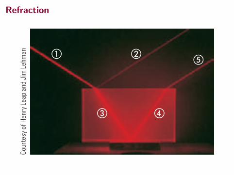
Q uick Quiz 35.2 If beam " is the incoming beam in Figure 35.10b, which of the other four red lines are reflected beams and which are refracted beams?
Refraction
1McGraw-Hill Concise Encyclopedia of Physics. c© 2002 by TheMcGraw-Hill Companies, Inc.
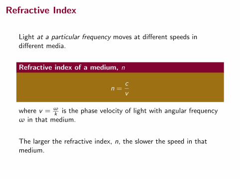
Refractive Index
Light at a particular frequency moves at different speeds indifferent media.
Refractive index of a medium, n
n =c
v
where v = ωk is the phase velocity of light with angular frequency
ω in that medium.
The larger the refractive index, n, the slower the speed in thatmedium.
Refraction
1066 Chapter 35 The Nature of Light and the Principles of Ray Optics
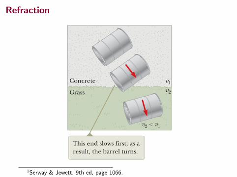
From Equation 35.3, we can infer that when light moves from a material in which its speed is high to a material in which its speed is lower as shown in Figure 35.11a, the angle of refraction u2 is less than the angle of incidence u1 and the ray is bent toward the normal. If the ray moves from a material in which light moves slowly to a material in which it moves more rapidly as illustrated in Figure 35.11b, then u2 is greater than u1 and the ray is bent away from the normal. The behavior of light as it passes from air into another substance and then re-emerges into air is often a source of confusion to students. When light travels in air, its speed is 3.00 3 108 m/s, but this speed is reduced to approximately 2 3 108 m/s when the light enters a block of glass. When the light re-emerges into air, its speed instantaneously increases to its original value of 3.00 3 108 m/s. This effect is far different from what happens, for example, when a bullet is fired through a block of wood. In that case, the speed of the bullet decreases as it moves through the wood because some of its original energy is used to tear apart the wood fibers. When the bullet enters the air once again, it emerges at a speed lower than it had when it entered the wood. To see why light behaves as it does, consider Figure 35.12, which represents a beam of light entering a piece of glass from the left. Once inside the glass, the light may encounter an electron bound to an atom, indicated as point A. Let’s assume light is absorbed by the atom, which causes the electron to oscillate (a detail repre-sented by the double-headed vertical arrows). The oscillating electron then acts as an antenna and radiates the beam of light toward an atom at B, where the light is again absorbed. The details of these absorptions and radiations are best explained in terms of quantum mechanics (Chapter 42). For now, it is sufficient to think of light passing from one atom to another through the glass. Although light travels from one atom to another at 3.00 3 108 m/s, the absorption and radiation that take place cause the average light speed through the material to fall to approximately 2 3 108 m/s. Once the light emerges into the air, absorption and radiation cease and the light travels at a constant speed of 3.00 3 108 m/s. A mechanical analog of refraction is shown in Figure 35.13. When the left end of the rolling barrel reaches the grass, it slows down, whereas the right end remains on the concrete and moves at its original speed. This difference in speeds causes the barrel to pivot, which changes the direction of travel.
Index of RefractionIn general, the speed of light in any material is less than its speed in vacuum. In fact, light travels at its maximum speed c in vacuum. It is convenient to define the index of refraction n of a medium to be the ratio
n ;speed of light in vacuum
speed of light in a medium;
cv (35.4)Index of refraction X
a b
GlassAir
v2
v1
GlassAir
v1v2
u2
Normal NormalWhen the light beam moves from air into glass, the light slows down upon entering the glass and its path is bent toward the normal.
When the beam moves from glass into air, the light speeds up upon entering the air and its path is bent away from the normal.
u1
u2 ! u1
v2 ! v1
u1
u2 " u1
v2 " v1
u2
Figure 35.11 The refraction of light as it (a) moves from air into glass and (b) moves from glass into air.
A B
Figure 35.12 Light passing from one atom to another in a medium. The blue spheres are electrons, and the vertical arrows represent their oscillations.
Concrete
Grass
This end slows first; as a result, the barrel turns.
v1
v2
v2 ! v1
Figure 35.13 Overhead view of a barrel rolling from concrete onto grass.
1Serway & Jewett, 9th ed, page 1066.
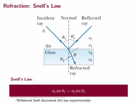
Refraction: Snell’s Law
GlassAir
A
B
Incidentray
Normal Reflectedray
Refractedray
u1
v1
v2
u2
u!1
Snell’s Law:
n1 sin θ1 = n2 sin θ2
1Willebrord Snell discovered this law experimentally.
n1
n2
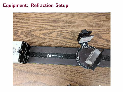
Equipment: Refraction Setup
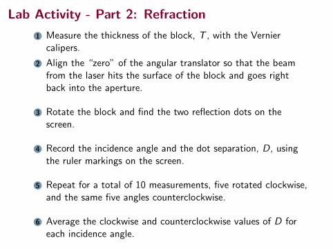
Lab Activity - Part 2: Refraction
1 Measure the thickness of the block, T , with the Verniercalipers.
2 Align the “zero” of the angular translator so that the beamfrom the laser hits the surface of the block and goes rightback into the aperture.
3 Rotate the block and find the two reflection dots on thescreen.
4 Record the incidence angle and the dot separation, D, usingthe ruler markings on the screen.
5 Repeat for a total of 10 measurements, five rotated clockwise,and the same five angles counterclockwise.
6 Average the clockwise and counterclockwise values of D foreach incidence angle.
Lab Activity - Part 2: Refraction
7 Calculate n for each value of the incidence angle. (Gives fivesamples ni .)
8 Find the average n and standard error on the sample mean.
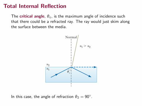
Total Internal Reflection
The critical angle, θc , is the maximum angle of incidence suchthat there could be a refracted ray. The ray would just skim alongthe surface between the media.
1074 Chapter 35 The Nature of Light and the Principles of Ray Optics
the raindrop. In the laboratory, rainbows have been observed in which the light makes more than 30 reflections before exiting the water drop. Because each reflec-tion involves some loss of light due to refraction of part of the incident light out of the water drop, the intensity of these higher-order rainbows is small compared with that of the primary rainbow.
Q uick Quiz 35.4 In photography, lenses in a camera use refraction to form an image on a light-sensitive surface. Ideally, you want all the colors in the light from the object being photographed to be refracted by the same amount. Of the mate-rials shown in Figure 35.21, which would you choose for a single- element camera lens? (a) crown glass (b) acrylic (c) fused quartz (d) impossible to determine
35.8 Total Internal ReflectionAn interesting effect called total internal reflection can occur when light is directed from a medium having a given index of refraction toward one having a lower index of refraction. Consider Figure 35.26a, in which a light ray travels in medium 1 and meets the boundary between medium 1 and medium 2, where n1 is greater than n2. In the figure, labels 1 through 5 indicate various possible direc-tions of the ray consistent with the wave under refraction model. The refracted rays are bent away from the normal because n1 is greater than n 2. At some particular angle of incidence uc , called the critical angle, the refracted light ray moves parallel to the boundary so that u2 5 90° (Fig. 35.26b). For angles of incidence greater than uc , the ray is entirely reflected at the boundary as shown by ray 5 in Figure 35.26a. We can use Snell’s law of refraction to find the critical angle. When u1 5 uc , u2 5 90° and Equation 35.8 gives
n1 sin uc 5 n2 sin 90° 5 n2
sin uc 5n 2
n 1 1 for n 1 . n 2 2 (35.10)
This equation can be used only when n1 is greater than n 2. That is, total internal reflection occurs only when light is directed from a medium of a given index of refraction toward a medium of lower index of refraction. If n1 were less than n2,
Critical angle for total Xinternal reflection
Figure 35.25 This photograph of a rainbow shows a distinct secondary rainbow with the colors reversed.
Mar
k D. P
hilli
ps/P
hoto
Res
earc
hers
, Inc
.
Figure 35.26 (a) Rays travel from a medium of index of refrac-tion n1 into a medium of index of refraction n2, where n2 , n1. (b) Ray 4 is singled out.
As the angle of incidence u1 increases, the angle of refraction u2 increases until u2 is 90! (ray 4). The dashed line indicates that no energy actually propagates in this direction.
The angle of incidence producing an angle of refraction equal to 90! is the critical angle uc . For angles greater than uc, all the energy of the incident light is reflected.
For even larger angles of incidence, total internal reflection occurs (ray 5).
3
Normal Normal
2
4
5
1
u2
u1 uc
n2n1
n2n1
n1 " n2 n1 " n2
a b
In this case, the angle of refraction θ2 = 90◦.
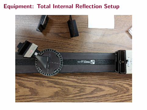
Equipment: Total Internal Reflection Setup
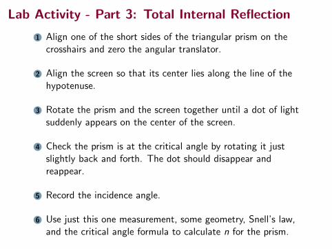
Lab Activity - Part 3: Total Internal Reflection
1 Align one of the short sides of the triangular prism on thecrosshairs and zero the angular translator.
2 Align the screen so that its center lies along the line of thehypotenuse.
3 Rotate the prism and the screen together until a dot of lightsuddenly appears on the center of the screen.
4 Check the prism is at the critical angle by rotating it justslightly back and forth. The dot should disappear andreappear.
5 Record the incidence angle.
6 Use just this one measurement, some geometry, Snell’s law,and the critical angle formula to calculate n for the prism.
Lab Activity
Does your result in part 1 confirm the law of reflection?
What index of refraction do you find for parts 2 and 3?