Embed Size (px)
Citation preview

self-directedL E A R N I N G essentialeducation
American Society of Radiologic Technologists
©2010 ASRT. All rights reserved.
Fluoroscopy: Mobile Unit Operation and Safety
1Fluoroscopy: Mobile Unit Operation and Safety www.asrt.org
essentialeducationself-directed
L E A R N I N G
After completing this article, readers should be able to:Describe the various components of a mobile fluoroscopic unit.Summarize the physical properties of mobile fluoroscopy image production and display. Position the mobile fluoroscopic unit to limit radiation exposure to the patient and medical staff.Discuss dose limits and radiation safety concepts related to mobile fluoroscopy imaging.
Fluoroscopy is a branch of radiology that allows physicians to see dynamic processes. Mobile fluoroscopic units, commonly referred to as “C-arms,” help make fluoroscopy available throughout a medical facility. To successfully operate this equipment in a variety of situations, the radiologic technologist or radiologist assistant must have in-depth knowledge of mobile fluoroscopy equipment.
This article discusses components that are common to most mobile fluoroscopy units. The operation of these units involves understanding specifics about the source, detector, optics and indicator systems. In addition, operators should be familiar with features of mobile fluoroscopy equipment that limit radiation exposure to patients and clinical personnel.
Chris Young, BS, R.R.A., R.T.(R)
Fluoroscopy: Mobile Unit Operation and Safety
Conventional radiography pro-vides remarkable diagnostic information on static anatomy. However, if used to demonstrate
a dynamic process, standard radiography produces a blurry image with motion artifact. Fluoroscopy provides real-time visualization of dynamic processes. The first recorded f luoroscopic procedure was performed with a cardboard box f lu-oroscope invented by Wilhelm Conrad Roentgen in 1895. Thomas Edison then developed conventional f luoroscopy in 1896, using a newer type of f luorescent screen. In 1937 Irving Langmuir was awarded the first patent for a f luoroscop-ic image intensifier. This initial design did not provide enough image intensifi-cation for clinical use and was modified by JW Coltman in 1948. Coltman’s mod-ifications resulted in a brightness gain of more than 1,000.
The first commercial image intensifier was produced by Westinghouse in 1953.1 The addition of the image intensifier to the f luoroscope paved the way for the widespread use of f luoroscopy. The image intensifier allowed the operator to per-form the procedures with photopic vision
and decreased the amount of radiation exposure necessary to produce a diag-nostic image. In 1955 the medical C-arm, which consisted of an image source and image receptor, was introduced.2
As f luoroscopy utilization increased, so did the desire and necessity to use the technology in areas of the hospital other than the radiology department, for exam-ple, in the surgical suite. In its company medical history, OEC Medical Systems Inc states that “… in the early 1970s, OEC introduced the first real-time [mobile] f luoroscopic imaging equip-ment in the United States … .”3 The use of mobile f luoroscopy became popular in the early 1980s when mobile C-arms were used in the operating suite for select orthopedic procedures.4 Mobile C-arms are used today throughout the world in a variety of settings, such as hospital operat-ing suites or outpatient clinics, to provide f luoroscopic guidance during orthopedic, neurologic, endovascular, urologic, neuro-vascular, spinal and cardiac procedures.2 In addition, mobile f luoroscopy equip-ment can be operated by a variety of pro-fessionals, including radiologist assistants (RAs) and radiologic technologists.
2Fluoroscopy: Mobile Unit Operation and Safety www.asrt.org
essentialeducationself-directed
L E A R N I N G
The operator can manipulate image orientation by rotating the image or altering the position in which the image is displayed on the monitor. The image may be rotated clockwise or counterclockwise by pushing the buttons with an open-circle arrow. Image display posi-tion may be altered by pushing the buttons that display “R” in various positions. Manipulating image orienta-tion is useful because patient position varies. By manip-ulating image orientation, the operator can ensure
Mobile Fluoroscopy UnitsEach mobile f luoroscopic assembly is made up of sev-
eral components, including a control panel, C-arm and monitor. Typically, the mobile f luoroscopic unit consists of 2 separate pieces: a C-arm and a control panel with monitors (see Figures 1-3). The operator inputs patient information and alters imaging factors that affect C-arm function at the control panel. Some smaller C-arm sys-tems, such as those used in orthopedic distal extrem-ity cases, may consist of only 1 unit. These units are designed so that a small C-arm attaches to the control panel and monitor assembly. The 2 components com-municate with one another via a cable that connects the C-arm to the control panel and monitors.
Control Panel Control panels are located on both the monitor
assembly and the C-arm to facilitate positioning the mobile f luoroscopy unit. Although control panel layout may vary by manufacturer, each control panel performs the same basic functions. For example, equipment manu-factured by GE Healthcare (Waukesha, Wisconsin) organizes the C-arm control panel into 5 main catego-ries: orientation, collimation, contrast, generator and workstation.
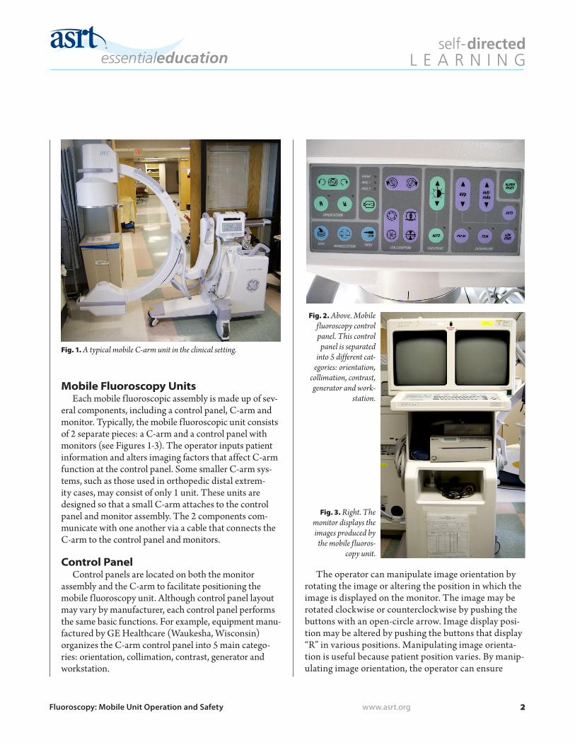
Fig. 1. A typical mobile C-arm unit in the clinical setting.
Fig. 2. Above. Mobile fluoroscopy control panel. This control panel is separated
into 5 different cat-egories: orientation,
collimation, contrast, generator and work-
station.
Fig. 3. Right. The monitor displays the images produced by the mobile fluoros-
copy unit.