Embed Size (px)
Citation preview
7/16/2019 FMU 100 (Z) - Inglés
http://slidepdf.com/reader/full/fmu-100-z-ingles 1/12
TechnicalInformationTI 149F/00/en
Application
The Watersonic FMU 100 (Z) ultrasonicmeasuring system is designed fornon-contact measurement of waterlevels in drinking and wastewatertreatment plants, pumping stations,drainage systems etc.. It comprises aplug-in FMU 100 (Z) card, Monorack
housing for wall-mounting and sensor• DU 100 (Z) for range max. 9 m or
• DU 101 (Z) for range max. 15 m.
In addition to standard analogueoutputs, three relays with freelyselectable switch points are availablefor control of level and pump or valvesequences.
Features and Benefits
• Economical stand-alone units forwater applications with 0/4…20 mA,0/2…10 V signal output and 3 relays.
• Rugged, seawater-proof sensor toIP 68 with one-piece diaphragm andseal: resistant to aggressive vapoursand condensates.
• Continuous measurement of liquids intanks, reservoirs, etc. of all shapesand sizes.
• Measurement independent of fluidproperties (density, conductivity) andpressure.
• Self-monitoring with immediateindication of fault condition.
• Intrinsically safe Z-versions designedfor [EEx ia] IIC applications. Allversions with electrically isolatedsensor circuit.
Ultrasonic Level Measurementwatersonic FMU 100 (Z)
For level measurement in water treatment plantsDesigned for use in explosion hazardous areas
The Watersonic FMU100 (Z) package
comprises the
FMU 100 (Z) plug-in
card, Monorack housing
and sensor DU 100 (Z)
or DU 101 (Z)
Hauser+EndressNothing beats know-how
7/16/2019 FMU 100 (Z) - Inglés
http://slidepdf.com/reader/full/fmu-100-z-ingles 2/12
Measuring Principle
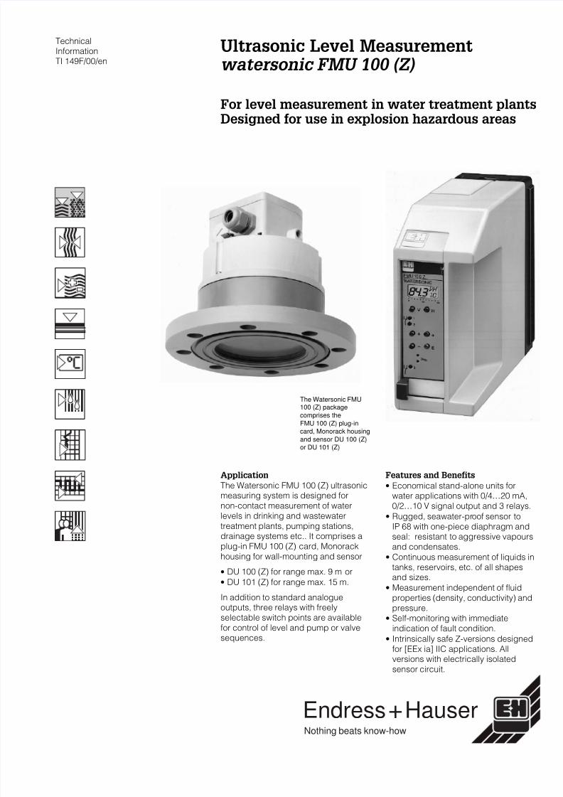
Ultrasonic Measurement
A sensor mounted above the productdirects an ultrasonic pulse through theair towards the product surface.
The product surface partially or fullyreflects the pulse back to the sensor.This echo is detected by the samesensor, now acting as a directionalmicrophone, and converted into anelectrical signal.
The time between transmission andreception of the pulse - the run time - isdirectly proportional to the distancebetween the sensor and the productsurface. The distance D is determinedfrom the velocity of sound c and the runtime t by the formula:
D = c * t/2 .
For C = 340 m/s, a run time of 10 mscorresponds to a transmission path of3.4 m and thus to a distance of 1.7 m.
Measuring Range
After the ultrasonic pulse has beenemitted the sensor requires time - theringing time - to stop vibrating.Consequently there is a zoneimmediately below the sensor fromwhich returning echoes cannot bedetected. This so-called blocking
distance determines the start of themeasuring range.
The end of the measuring range isdetermined by the attenuation of theultrasonic pulse by the air as well as bythe strength of the reflection from theproduct surface.
Performance
• The measurement is independent ofproduct properties such as specific
gravity, conductivity, viscosity anddielectric constant.
• The measurement is unaffected bychanges in ambient temperaturewithin the tank or well: theFMU 100 (Z) transmitter compensatesby using the information delivered bythe temperature sensor built into theDU 100 (Z)/101 (Z).
• Depending on the DU… sensoremployed, the measuring range is upto 9 m or up to 15 m.
Ultrasonic measuring
principleD = Distance sensor –
product surface
B = Blocking distance
2
7/16/2019 FMU 100 (Z) - Inglés
http://slidepdf.com/reader/full/fmu-100-z-ingles 3/12
Measuring System
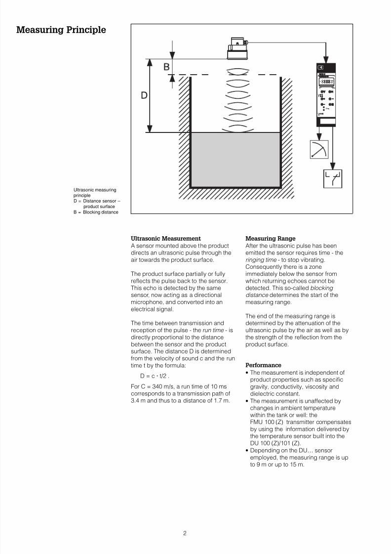
Input Signal
A three-core installation cable connectsthe FMU 100 (Z) transmitter to theDU 100 (Z)/101 (Z) ultrasonic sensor.The FMU 100 (Z) transmitter inMonorack housing supplies power andthe sensor sends back an echo signal.This is converted to a level or volumeindication. The measured value isdisplayed at the front panel.
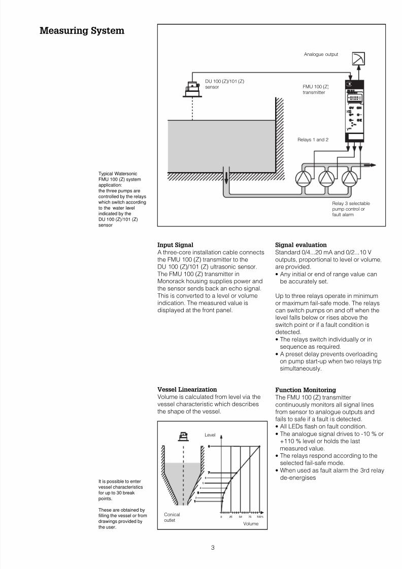
Vessel Linearization
Volume is calculated from level via thevessel characteristic which describesthe shape of the vessel.
Signal evaluation
Standard 0/4...20 mA and 0/2...10 Voutputs, proportional to level or volume,are provided.
• Any initial or end of range value canbe accurately set.
Up to three relays operate in minimumor maximum fail-safe mode. The relayscan switch pumps on and off when thelevel falls below or rises above theswitch point or if a fault condition isdetected.
• The relays switch individually or insequence as required.
• A preset delay prevents overloadingon pump start-up when two relays tripsimultaneously.
Function Monitoring
The FMU 100 (Z) transmittercontinuously monitors all signal linesfrom sensor to analogue outputs andfails to safe if a fault is detected.
• All LEDs flash on fault condition.
• The analogue signal drives to -10 % or+110 % level or holds the lastmeasured value.
• The relays respond according to theselected fail-safe mode.
• When used as fault alarm the 3rd relayde-energises
Level
Volume
Conicaloutlet
DU 100 (Z)/101 (Z)
sensor
Relays 1 and 2
Relay 3 selectablepump control orfault alarm
Analogue output
FMU 100 (Z)
transmitter
It is possible to enter
vessel characteristics
for up to 30 break
points.
These are obtained byfilling the vessel or from
drawings provided by
the user.
Typical Watersonic
FMU 100 (Z) system
application:
the three pumps are
controlled by the relays
which switch according
to the water level
indicated by the
DU 100 (Z)/101 (Z)
sensor
3
7/16/2019 FMU 100 (Z) - Inglés
http://slidepdf.com/reader/full/fmu-100-z-ingles 4/12
Operation
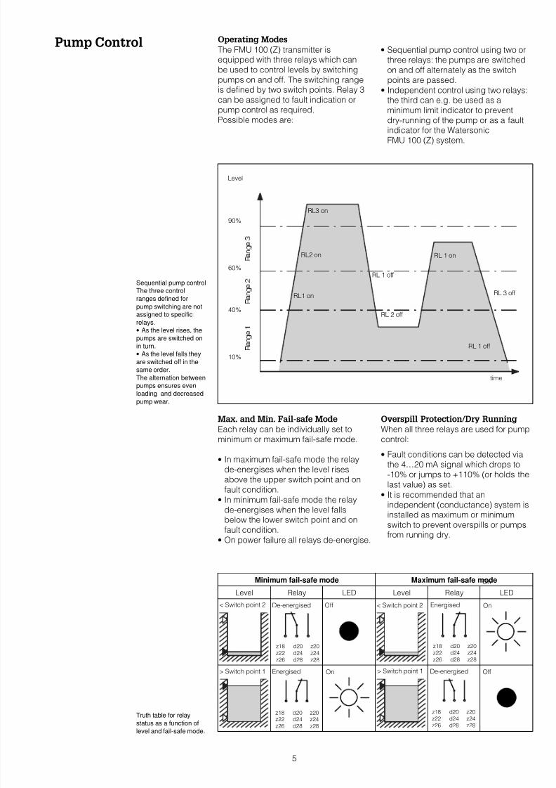
Interference Echo Suppression
The echo suppression function ensuresthat measurements can still be madewhen interference echoes, caused bypermanent fixtures, are present in thesignal.
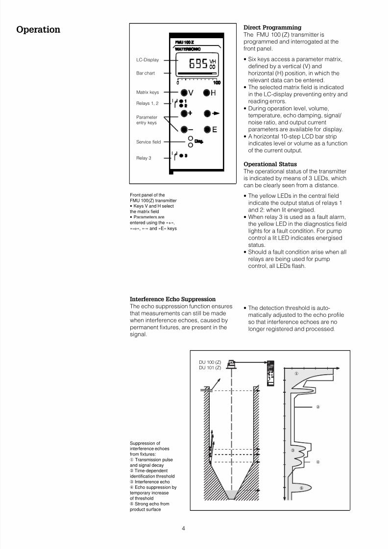
Direct Programming
The FMU 100 (Z) transmitter isprogrammed and interrogated at thefront panel.
• Six keys access a parameter matrix,defined by a vertical (V) andhorizontal (H) position, in which therelevant data can be entered.
• The selected matrix field is indicated
in the LC-display preventing entry andreading errors.
• During operation level, volume,temperature, echo damping, signal/ noise ratio, and output currentparameters are available for display.
• A horizontal 10-step LCD bar stripindicates level or volume as a functionof the current output.
Operational Status
The operational status of the transmitteris indicated by means of 3 LEDs, whichcan be clearly seen from a distance.
• The yellow LEDs in the central fieldindicate the output status of relays 1and 2: when lit energised.
• When relay 3 is used as a fault alarm,the yellow LED in the diagnostics fieldlights for a fault condition. For pumpcontrol a lit LED indicates energisedstatus.
• Should a fault condition arise when allrelays are being used for pumpcontrol, all LEDs flash.
• The detection threshold is auto-matically adjusted to the echo profileso that interference echoes are nolonger registered and processed.
LC-Display
Bar chart
Matrix keys
Relays 1, 2
Parameterentry keys
Relay 3
Service field
Suppression ofinterference echoes
from fixtures:
x Transmission pulse
and signal decay
y Time-dependent
identification threshold
z Interference echo Echo suppression by
temporary increase
of threshold
| Strong echo from
product surface
x
z
|
DU 100 (Z)
DU 101 (Z)
y
Front panel of the
FMU 100(Z) transmitter
• Keys V and H select
the matrix field
• Parameters are
entered using the »+«,
»⇒«, »-« and »E« keys
4
7/16/2019 FMU 100 (Z) - Inglés
http://slidepdf.com/reader/full/fmu-100-z-ingles 5/12
Pump Control Operating Modes
The FMU 100 (Z) transmitter isequipped with three relays which canbe used to control levels by switchingpumps on and off. The switching rangeis defined by two switch points. Relay 3can be assigned to fault indication orpump control as required.Possible modes are:
Max. and Min. Fail-safe Mode
Each relay can be individually set tominimum or maximum fail-safe mode.
• In maximum fail-safe mode the relayde-energises when the level risesabove the upper switch point and onfault condition.
• In minimum fail-safe mode the relayde-energises when the level fallsbelow the lower switch point and onfault condition.
• On power failure all relays de-energise..
• Sequential pump control using two orthree relays: the pumps are switchedon and off alternately as the switchpoints are passed.
• Independent control using two relays:the third can e.g. be used as aminimum limit indicator to preventdry-running of the pump or as a faultindicator for the Watersonic
FMU 100 (Z) system.
Overspill Protection/Dry Running
When all three relays are used for pumpcontrol:
• Fault conditions can be detected viathe 4…20 mA signal which drops to-10% or jumps to +110% (or holds thelast value) as set.
• It is recommended that anindependent (conductance) system isinstalled as maximum or minimumswitch to prevent overspills or pumpsfrom running dry.
De-energised Off
On OffEnergised > Switch point 1
< Switch point 2 On
RL1 on
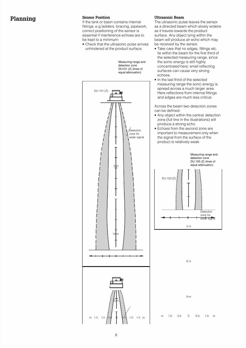
RL2 on
RL3 on
RL 1 off
RL 2 off
RL 1 on
RL 3 off
RL 1 off
90%
60%
40%
10%
time
Level
Sequential pump control
The three control
ranges defined for
pump switching are not
assigned to specific
relays.
• As the level rises, the
pumps are switched on
in turn.
• As the level falls they
are switched off in the
same order.
The alternation between
pumps ensures even
loading and decreased
pump wear.
Minimum fail-safe mode Maximum fail-safe mode
Level Relay LED Level Relay LED
Truth table for relay
status as a function of
level and fail-safe mode.
De-energised
z18 d20 z20z22 d24 z24
z26 d28 z28
On
< Switch point 2
> Switch point 1
z18 d20 z20z22 d24 z24
z26 d28 z28
z18 d20 z20
z22 d24 z24z26 d28 z28
z18 d20 z20
z22 d24 z24
z26 d28 z28
Energised
5
7/16/2019 FMU 100 (Z) - Inglés
http://slidepdf.com/reader/full/fmu-100-z-ingles 6/12
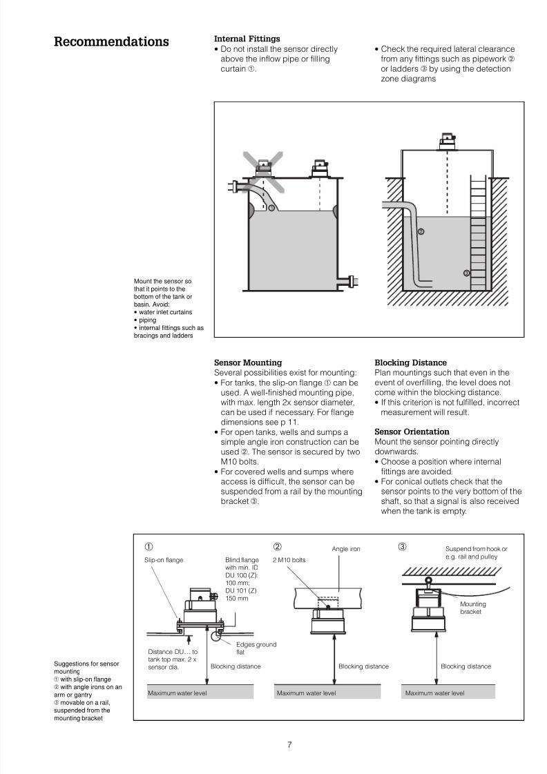
Planning Sensor Position
If the tank or basin contains internalfittings, e.g ladders, bracing, pipework,correct positioning of the sensor isessential if interference echoes are tobe kept to a minimum:
• Check that the ultrasonic pulse arrivesunhindered at the product surface.
Ultrasonic Beam
The ultrasonic pulse leaves the sensoras a directed beam which slowly widensas it travels towards the productsurface. Any object lying within thebeam will produce an echo which maybe received by the sensor.
• Take care that no edges, fittings etc.lie within the beam for the first third ofthe selected measuring range, since
the sonic energy is still highlyconcentrated here: small reflectingsurfaces can cause very strongechoes.
• In the last third of the selectedmeasuring range the sonic energy isspread across a much larger area.Here reflections from internal fittingsand edges are much less critical.
Across the beam two detection zonescan be defined:
• Any object within the central detectionzone (full line in the illustrations) willproduce a strong echo.
• Echoes from the second zone areimportant to measurement only whenthe signal from the surface of theproduct is relatively weak.
Detectionzone forweak signal
Detectionzone forweak signal
DU 100 (Z)
m 1.0 0.5 0 0.5 1.0 m
3 m
9 m
6 m
m 1.5 1.0 0.5 0 0.5 1.0 1.5 m
DU 101 (Z)
5 m
10 m
15 m
Measuring range and
detection zone
DU 100 (Z) (lines of
equal attenuation)
Measuring range anddetection zone
DU101 (Z) (lines of
equal attenuation)
6
7/16/2019 FMU 100 (Z) - Inglés
http://slidepdf.com/reader/full/fmu-100-z-ingles 7/12
Recommendations Internal Fittings
• Do not install the sensor directlyabove the inflow pipe or fillingcurtain .
Sensor Mounting
Several possibilities exist for mounting:
• For tanks, the slip-on flange can beused. A well-finished mounting pipe,with max. length 2x sensor diameter,can be used if necessary. For flangedimensions see p 11.
• For open tanks, wells and sumps asimple angle iron construction can beused . The sensor is secured by twoM10 bolts.
• For covered wells and sumps whereaccess is difficult, the sensor can besuspended from a rail by the mountingbracket.
• Check the required lateral clearancefrom any fittings such as pipework or ladders by using the detectionzone diagrams
Blocking Distance
Plan mountings such that even in theevent of overfilling, the level does notcome within the blocking distance.
• If this criterion is not fulfilled, incorrectmeasurement will result.
Sensor Orientation
Mount the sensor pointing directlydownwards.
• Choose a position where internalfittings are avoided.
• For conical outlets check that thesensor points to the very bottom of theshaft, so that a signal is also receivedwhen the tank is empty.
Mount the sensor so
that it points to the
bottom of the tank or
basin. Avoid:
• water inlet curtains
• piping
• internal fittings such as
bracings and ladders
Blocking distance Blocking distance Blocking distance
Slip-on flange 2 M10 bolts
Mountingbracket
Maximum water level Maximum water levelMaximum water level
Distance DU… totank top max. 2 x
sensor dia.
Edges groundflat
Suspend from hook or
e.g. rail and pulley
Angle iron
Blind flangewith min. ID
DU 100 (Z):100 mm;
DU 101 (Z)
150 mm
Suggestions for sensor
mounting
with slip-on flange with angle irons on an
arm or gantry
movable on a rail,
suspended from the
mounting bracket
7
7/16/2019 FMU 100 (Z) - Inglés
http://slidepdf.com/reader/full/fmu-100-z-ingles 8/12
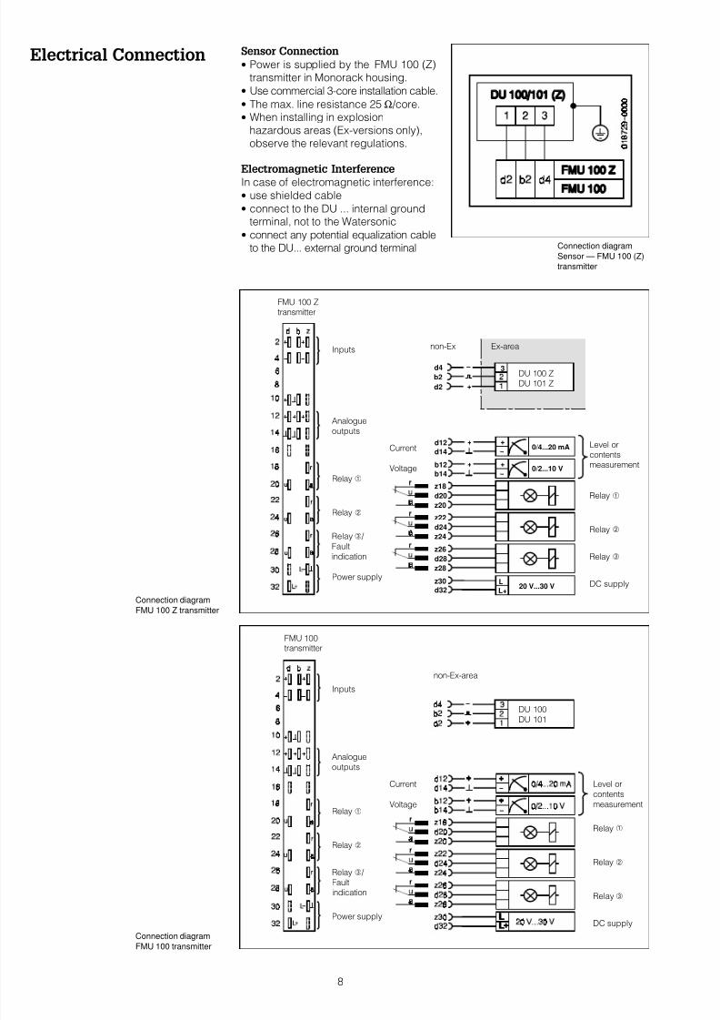
Electrical Connection Sensor Connection
• Power is supplied by the FMU 100 (Z)transmitter in Monorack housing.
• Use commercial 3-core installation cable.
• The max. line resistance 25 Ω /core.
• When installing in explosionhazardous areas (Ex-versions only),observe the relevant regulations.
Electromagnetic Interference
In case of electromagnetic interference:• use shielded cable
• connect to the DU ... internal groundterminal, not to the Watersonic
• connect any potential equalization cableto the DU... external ground terminal
Connection diagram
FMU 100 Z transmitter
u
u
u
L
L+
z30
d32
z18
d20
z20
z22
d24
z24
20 V...30 V
z28
d28
z26
+ +0/2...10 V
b14
b12
++d12
d140/4...20 mA
d4
b2
d2 +
3
FMU 100 Ztransmitter
Inputs
Analogue
outputs
Relay
non-Ex Ex-area
DU 100 ZDU 101 Z
Level orcontentsmeasurement
Relay
Relay
Power supply
Relay
Relay
DC supply
Voltage
Current
Relay / Fault
indication
Connection diagram
Sensor — FMU 100 (Z)
transmitter
Connection diagram
FMU 100 transmitter
FMU 100transmitter
Inputs
Analogue
outputs
Relay
non-Ex-area
DU 100
DU 101
Level or
contents
measurement
Relay
Relay
Power supply
Relay
Relay
DC supply
Voltage
Current
Relay /
Fault
indication
8
7/16/2019 FMU 100 (Z) - Inglés
http://slidepdf.com/reader/full/fmu-100-z-ingles 9/12
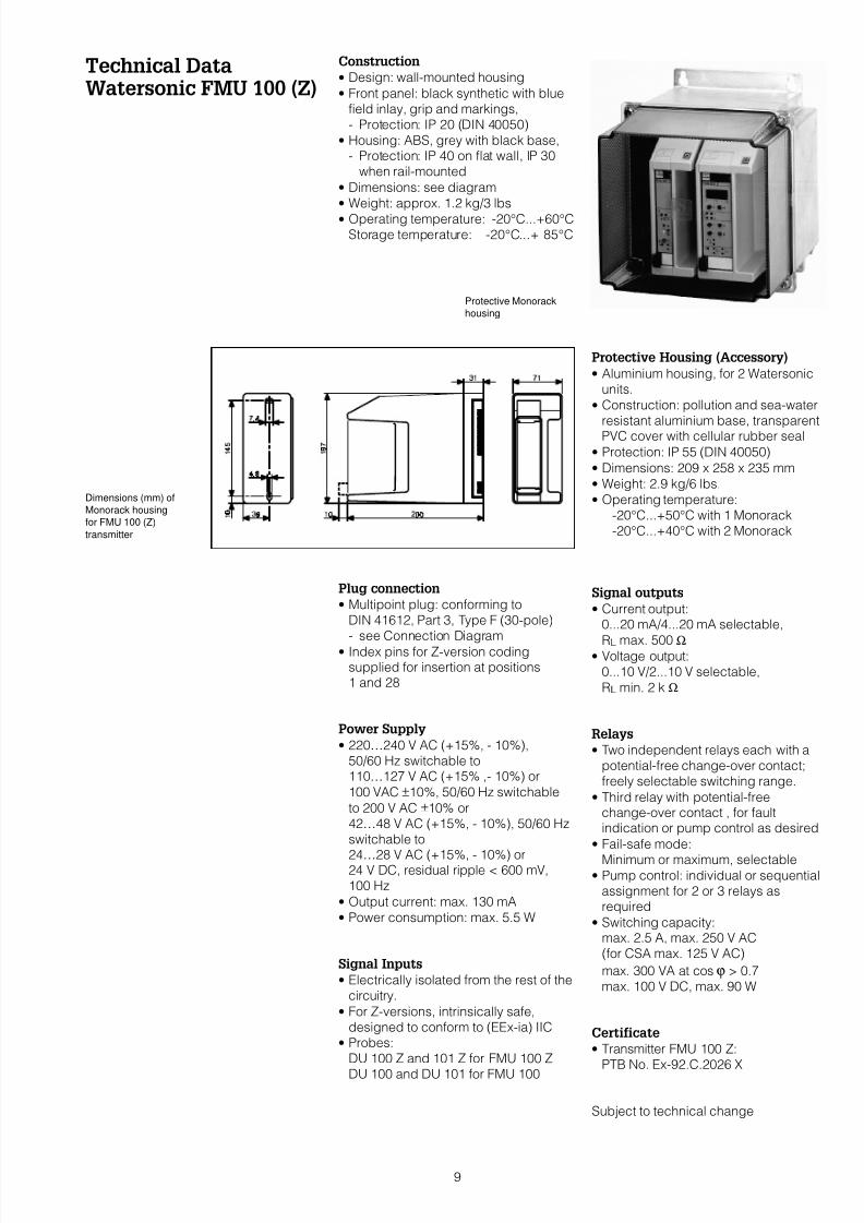
Technical DataWatersonic FMU 100 (Z)
Construction
• Design: wall-mounted housing
• Front panel: black synthetic with bluefield inlay, grip and markings,- Protection: IP 20 (DIN 40050)
• Housing: ABS, grey with black base,- Protection: IP 40 on flat wall, IP 30
when rail-mounted
• Dimensions: see diagram
• Weight: approx. 1.2 kg/3 lbs
• Operating temperature: -20°C...+60°CStorage temperature: -20°C...+ 85°C
Plug connection
• Multipoint plug: conforming toDIN 41612, Part 3, Type F (30-pole)- see Connection Diagram
• Index pins for Z-version codingsupplied for insertion at positions1 and 28
Power Supply
• 220…240 V AC (+15%, - 10%),50/60 Hz switchable to110…127 V AC (+15% ,- 10%) or
100 VAC ±10%, 50/60 Hz switchable
to 200 V AC ±10% or42…48 V AC (+15%, - 10%), 50/60 Hzswitchable to
24…28 V AC (+15%, - 10%) or24 V DC, residual ripple < 600 mV,100 Hz
• Output current: max. 130 mA
• Power consumption: max. 5.5 W
Signal Inputs
• Electrically isolated from the rest of thecircuitry.
• For Z-versions, intrinsically safe,designed to conform to (EEx-ia) IIC
• Probes:DU 100 Z and 101 Z for FMU 100 Z
DU 100 and DU 101 for FMU 100
Protective Housing (Accessory)
• Aluminium housing, for 2 Watersonicunits.
• Construction: pollution and sea-waterresistant aluminium base, transparentPVC cover with cellular rubber seal
• Protection: IP 55 (DIN 40050)
• Dimensions: 209 x 258 x 235 mm
• Weight: 2.9 kg/6 lbs.
• Operating temperature:-20°C...+50°C with 1 Monorack-20°C...+40°C with 2 Monorack
Signal outputs
• Current output:0...20 mA/4...20 mA selectable,
RL max. 500 Ω• Voltage output:
0...10 V/2...10 V selectable,
RL min. 2 k Ω
Relays
• Two independent relays each with apotential-free change-over contact;freely selectable switching range.
• Third relay with potential-freechange-over contact , for faultindication or pump control as desired
• Fail-safe mode:
Minimum or maximum, selectable• Pump control: individual or sequential
assignment for 2 or 3 relays asrequired
• Switching capacity:max. 2.5 A, max. 250 V AC(for CSA max. 125 V AC)
max. 300 VA at cos ϕ > 0.7max. 100 V DC, max. 90 W
Certificate
• Transmitter FMU 100 Z:PTB No. Ex-92.C.2026 X
Subject to technical change
Protective Monorack
housing
Dimensions (mm) of
Monorack housing
for FMU 100 (Z)
transmitter
9
7/16/2019 FMU 100 (Z) - Inglés
http://slidepdf.com/reader/full/fmu-100-z-ingles 10/12
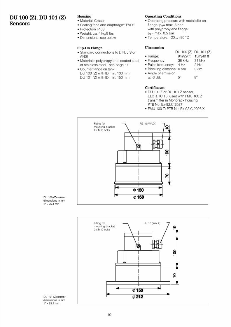
DU 100 (Z), DU 101 (Z)Sensors
Housing
• Material: Crastin
• Sealing face and diaphragm: PVDF
• Protection IP 68
• Weight: ca. 4 kg/9 lbs
• Dimensions: see below
Slip-On Flange
• Standard connections to DIN, JIS or
ANSI• Materials: polypropylene, coated steel
or stainless steel - see page 11 -
• Counterflange on tank:DU 100 (Z) with ID min. 100 mmDU 101 (Z) with ID min. 150 mm
Operating Conditions
• Operating pressure with metal slip-onflange: pe= max. 3 barwith polypropylene flange:pe= max. 0.5 bar
• Temperature: –20…+80 °C
Ultrasonics
DU 100 (Z) DU 101 (Z)
• Range: 9m/29 ft 15m/49 ft• Frequency: 38 kHz 31 kHz
• Pulse frequency: 4 Hz 2 Hz
• Blocking distance: 0.5m 0.8m
• Angle of emissionat -3 dB: 5° 8°
Certificates
• DU 100 Z or DU 101 Z sensor,EEx ia IIC T5, used with FMU 100 Ztransmitter in Monorack housing:PTB No. Ex-92.C.2027
• FMU 100 Z: PTB No. Ex-92.C.2026 X
Fitting formounting bracket
2 x M10 bolts
PG 16 (WADI)
Fitting formounting bracket
2 x M10 bolts
PG 16 (WADI)
DU 100 (Z) sensor
dimensions in mm
1" = 25.4 mm
DU 101 (Z) sensor
dimensions in mm
1" = 25.4 mm
10
7/16/2019 FMU 100 (Z) - Inglés
http://slidepdf.com/reader/full/fmu-100-z-ingles 11/12
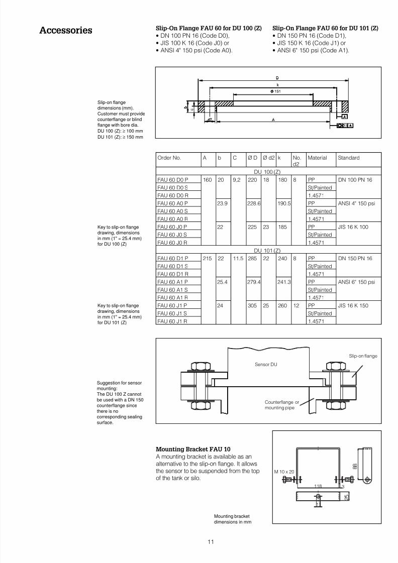
Accessories Slip-On Flange FAU 60 for DU 100 (Z)
• DN 100 PN 16 (Code D0),
• JIS 100 K 16 (Code J0) or
• ANSI 4" 150 psi (Code A0).
Mounting Bracket FAU 10
A mounting bracket is available as analternative to the slip-on flange. It allowsthe sensor to be suspended from the topof the tank or silo.
Slip-On Flange FAU 60 for DU 101 (Z)
• DN 150 PN 16 (Code D1),
• JIS 150 K 16 (Code J1) or
• ANSI 6" 150 psi (Code A1).
Order No. A b C Ø D Ø d2 k No.d2
Material Standard
DU 100 (Z)
FAU 60 D0 P 160 20 9,2 220 18 180 8 PP DN 100 PN 16
FAU 60 D0 S St/Painted
FAU 60 D0 R 1.4571FAU 60 A0 P 23.9 228.6 190.5 PP ANSI 4" 150 psi
FAU 60 A0 S St/Painted
FAU 60 A0 R 1.4571
FAU 60 J0 P 22 225 23 185 PP JIS 16 K 100
FAU 60 J0 S St/Painted
FAU 60 J0 R 1.4571
DU 101 (Z)
FAU 60 D1 P 215 22 11.5 285 22 240 8 PP DN 150 PN 16
FAU 60 D1 S St/Painted
FAU 60 D1 R 1.4571
FAU 60 A1 P 25.4 279.4 241.3 PP ANSI 6" 150 psi
FAU 60 A1 S St/Painted
FAU 60 A1 R 1.4571
FAU 60 J1 P 24 305 25 260 12 PP JIS 16 K 150
FAU 60 J1 S St/Painted
FAU 60 J1 R 1.4571
Mounting bracket
dimensions in mm
Key to slip-on flange
drawing, dimensions
in mm (1" = 25.4 mm)
for DU 101 (Z)
Slip-on flange
dimensions (mm).
Customer must provide
counterflange or blind
flange with bore dia.
DU 100 (Z): ≥ 100 mm
DU 101 (Z): ≥ 150 mm
M 10 x 20
118 3
11
Sensor DU
Counterflange ormounting pipe
Slip-on flange
Suggestion for sensor
mounting:
The DU 100 Z cannotbe used with a DN 150
counterflange since
there is no
corresponding sealing
surface.
Key to slip-on flange
drawing, dimensions
in mm (1" = 25.4 mm)
for DU 100 (Z)
11
7/16/2019 FMU 100 (Z) - Inglés
http://slidepdf.com/reader/full/fmu-100-z-ingles 12/12
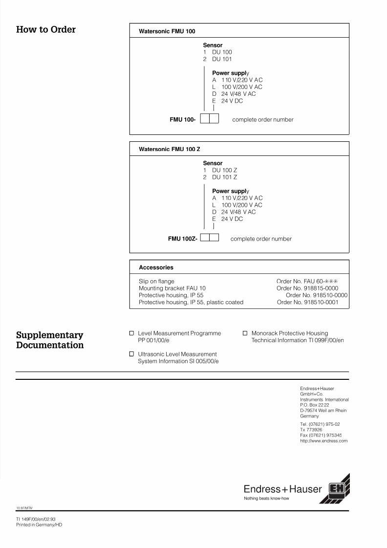
How to Order
Level Measurement ProgrammePP 001/00/e
Ultrasonic Level MeasurementSystem Information SI 005/00/e
Monorack Protective HousingTechnical Information TI 099F/00/en
TI 149F/00/en/02.93
Printed in Germany/HD
Watersonic FMU 100
Sensor1 DU 1002 DU 101
Power supplyA 110 V/220 V ACL 100 V/200 V AC
D 24 V/48 V ACE 24 V DC
FMU 100- complete order number
Watersonic FMU 100 Z
Sensor1 DU 100 Z2 DU 101 Z
Power supplyA 110 V/220 V ACL 100 V/200 V ACD 24 V/48 V ACE 24 V DC
FMU 100Z- complete order number
Accessories
Slip on flange Order No. FAU 60-FFF
Mounting bracket FAU 10 Order No. 918815-0000Protective housing, IP 55 Order No. 918510-0000Protective housing, IP 55, plastic coated Order No. 918510-0001
SupplementaryDocumentation
10.97/MTM
Endress+Hauser
GmbH+Co.
Instruments InternationalP.O. Box 22 22
D-79574 Weil am Rhein
Germany
Tel. (07621) 975-02
Tx 773926
Fax (07621) 975345
http://www.endress.com
Hauser+EndressNothing beats know-how