Embed Size (px)
Citation preview
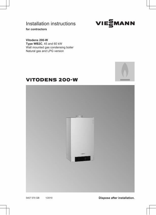
Installation instructionsfor contractors
VIESMANN
Vitodens 200-WType WB2C, 45 and 60 kWWall mounted gas condensing boiler Natural gas and LPG version
VITODENS 200-W
5457 570 GB 1/2010 Dispose after installation.
2
Please follow these safety instructions closely to prevent accidents and mate-rial losses.
Safety instructions explained
DangerThis symbol warns against therisk of injury.
! Please noteThis symbol warns against therisk of material losses and envi-ronmental pollution.
NoteDetails identified by the word "Note" con-tain additional information.
Target group
These instructions are exclusivelydesigned for qualified personnel.■ Work on gas appliances must only be
carried out by a qualified gas fitter.■ Work on electrical equipment must
only be carried out by a qualified elec-trician.
Regulations
Observe the following when working onthis system■ all legal instructions regarding the pre-
vention of accidents,■ all legal instructions regarding envi-
ronmental protection,
■ the Code of Practice of relevant tradeassociations,
■ all current safety regulations asdefined by DIN, EN, DVGW, TRGI,TRF, VDE and all locally applicablestandards.
Working on the system
■ Isolate the system from the power sup-ply and check that it is no longer 'live',e.g. by removing a separate fuse or bymeans of a mains isolator.
■ Safeguard the system against unau-thorised reconnection.
■ When using gas as fuel, also close themain gas shut-off valve and safeguardagainst unauthorised reopening.
Safety instructions
5457
570
GB
3
Preparing for installationProduct information.............................................................................................. 4Preparing for installation....................................................................................... 5■ Preparing the boiler installation......................................................................... 5
Installation sequenceInstalling the boiler and making all connections................................................... 7■ Wall mounting bracket installation.................................................................... 7■ Hanging the boiler into the wall mounting bracket............................................ 8Heating water side connection............................................................................. 9Flue gas connection............................................................................................. 9Condensate connection........................................................................................ 10Gas connection.................................................................................................... 10Opening the control unit casing............................................................................ 11Electrical connections........................................................................................... 13■ Routing the connecting cables.......................................................................... 15■ Replacing the boiler coding card for installation in a multi-boiler system.......... 16Closing the control unit casing and inserting the programming unit..................... 17Fitting the front panel............................................................................................ 19Commissioning and adjustment........................................................................... 20
Index54
57 5
70 G
B
4
Vitodens 200-W, WB2C
Set up for operation with natural gas E and LL. For conversion to LPG P (without conversion kit), see the service instructions.
Conversion for other target countriesThe Vitodens 200-W should generally only be delivered to those countries specifiedon the type plate. For deliveries to alternative countries, an approved contractor, onhis own initiative, must arrange individual approval in accordance with the law of theland.
Multi-boiler systemIn connection with the installation of a multi-boiler system observe the installationinstructions of the multi-boiler system accessories.For installations in a multi-boiler system, generally the boiler coding card needs to bereplaced (see page 16).
Product information
5457
570
GB
5
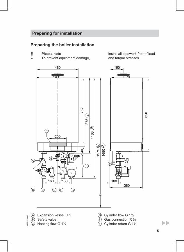
Preparing the boiler installation
! Please noteTo prevent equipment damage,
install all pipework free of loadand torque stresses.
40
100160 160
200
752
1975
1690
850
380
480
875
1166
160
EA
L
M
O
CB D F G
H
PK
N
A Expansion vessel G 1B Safety valveC Heating flow G 1½
D Cylinder flow G 1½E Gas connection R ¾F Cylinder return G 1½
Preparing for installation54
57 5
70 G
B
6
G Heating return G 1½H Cable entry area at the backK Accessories (connection sets)L Without connection sets (accesso-
ries)M With connection sets (accessories)
N Recommended dimension (singleboiler system)
O Recommended dimension (multi-boiler system)
P Condensate drain
NoteThis boiler (protection IP X4 D) isapproved for installation in wet roomsinside protection area 1 according toDIN VDE 0100 [Germany], if hosedwater can be prevented.Observe the requirements ofDIN VDE 0100 [or local regulations].
1. Prepare the water connections. Flushthe heating system thoroughly.
2. Prepare the gas connection accord-ing to TRGI or TRF [or local regula-tions].
3. Prepare the electrical connections.■ Power supply cable: NYM-
J 3 x 1.5 mm2, fuse max. 16 A,230 V~.
■ Accessory cables: NYM with therequired number of conductors forthe external connections.
■ Allow all cables in area "H" to pro-trude 1200 mm from the wall.
Preparing for installation (cont.)
5457
570
GB
7
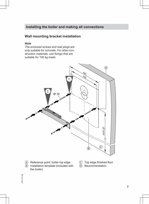
Wall mounting bracket installation
NoteThe enclosed screws and rawl plugs areonly suitable for concrete. For other con-struction materials, use fixings that aresuitable for 100 kg loads.
422
480
1975
Ø 10
1.
2.
A
D
CB
A Reference point: boiler top edgeB Installation template (included with
the boiler)
C Top edge finished floorD Recommendation
Installing the boiler and making all connections54
57 5
70 G
B
8
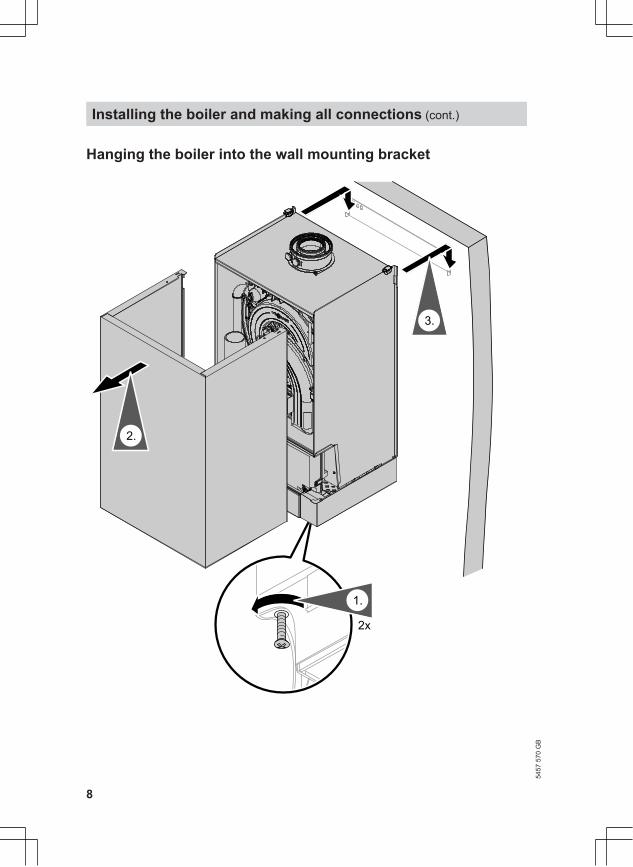
Hanging the boiler into the wall mounting bracket
2x
1.
3.
2.
Installing the boiler and making all connections (cont.)
5457
570
GB
9
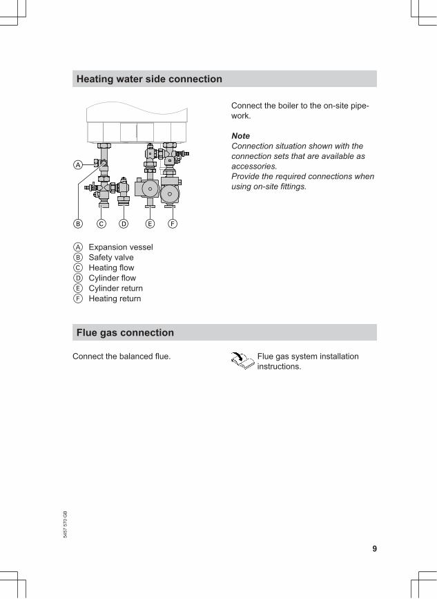
CB D E F
A
A Expansion vesselB Safety valveC Heating flow D Cylinder flowE Cylinder return F Heating return
Connect the boiler to the on-site pipe-work.
NoteConnection situation shown with theconnection sets that are available asaccessories.Provide the required connections whenusing on-site fittings.
Flue gas connection
Connect the balanced flue. Flue gas system installationinstructions.
Heating water side connection54
57 5
70 G
B
10
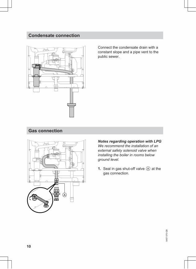
Connect the condensate drain with aconstant slope and a pipe vent to thepublic sewer.
Gas connection
A
Notes regarding operation with LPGWe recommend the installation of anexternal safety solenoid valve wheninstalling the boiler in rooms belowground level.
1. Seal in gas shut-off valve A at thegas connection.
Condensate connection
5457
570
GB
11
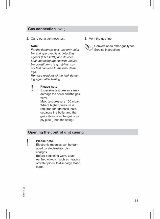
2. Carry out a tightness test.
NoteFor the tightness test, use only suita-ble and approved leak detectingagents (EN 14291) and devices.Leak detecting agents with unsuita-ble constituents (e.g. nitrites, sul-phides) can lead to material dam-age.Remove residues of the leak detect-ing agent after testing.
! Please noteExcessive test pressure maydamage the boiler and the gasvalve. Max. test pressure 150 mbar.Where higher pressure isrequired for tightness tests,separate the boiler and thegas valves from the gas sup-ply pipe (undo the fitting).
3. Vent the gas line.
Conversion to other gas types: Service instructions
Opening the control unit casing
! Please noteElectronic modules can be dam-aged by electrostatic dis-charges.Before beginning work, touchearthed objects, such as heatingor water pipes, to discharge staticloads.
Gas connection (cont.)
5457
570
GB
12
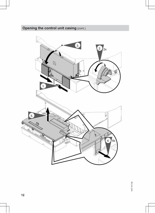
3.2. 2x
1.
4. 8x
5.
Opening the control unit casing (cont.)
5457
570
GB
13
5
2
1
3217654X3
40962035100
L 1
L N230V~
LN230V~
96 401
A C
D
LN20
B
X4
145145
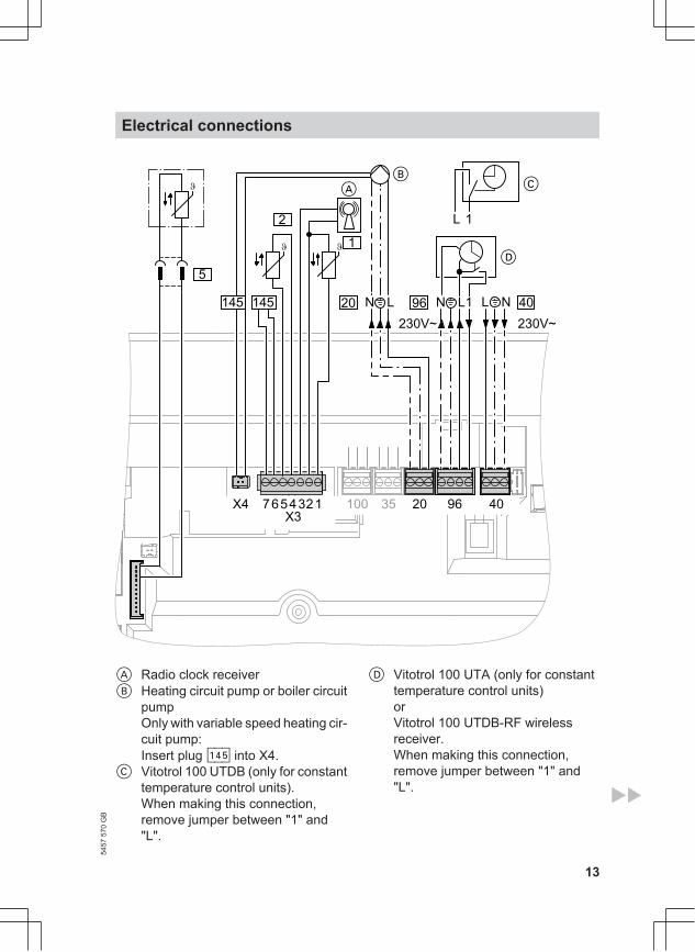
A Radio clock receiverB Heating circuit pump or boiler circuit
pumpOnly with variable speed heating cir-cuit pump:Insert plug aVG into X4.
C Vitotrol 100 UTDB (only for constanttemperature control units).When making this connection,remove jumper between "1" and"L".
D Vitotrol 100 UTA (only for constanttemperature control units)orVitotrol 100 UTDB-RF wirelessreceiver.When making this connection,remove jumper between "1" and"L".
Electrical connections54
57 5
70 G
B
14
Information regarding the con-nection of accessoriesFor the connection, observe theseparate installation instructionsprovided with the accessory com-ponents.
230 V~ plugssÖ Circulation pumpfÖ Power supply [terminals]
DangerIncorrect core terminationcan cause severe injuriesand damage to the equip-ment.Take care not to interchangewires "L1" and "N".
■ Install an isolator in the powersupply line that simultaneouslyisolates all non-earthed conduc-tors from the mains with at least3 mm contact separation.We additionally recommendinstalling an AC/DC-sensitiveRCD (RCD class B ) forDC (fault) currents that can occurwith energy-efficient equipment.
■ Max. fuse rating 16 A.
lH ■ Power supply accessories (230 V/50 Hz). Where the boiler is instal-led in a wet area, the connectionof accessories to the power sup-ply must not be carried out at thecontrol unit. The power supplyconnection for accessories can bemade immediately at the controlunit, if the boiler is installed out-side wet areas. This connection isdirectly controlled with the systemON/OFF switch (max. 3 A).
■ Vitotrol 100 UTA■ Vitotrol 100 UTDB■ Vitotrol 100 UTDB-RF
Low voltage plugs! Outside temperature sensor (only
for weather-compensated controlunits).
Installation:■ North or north-western wall, 2 to
2.5 m above ground level; inmulti-storey buildings, in theupper half of the second floor
■ Not above windows, doors orventilation outlets
■ Not immediately below balco-nies or gutters
■ Never render over■ 2-core lead, max. 35 m length
with a cross-section of 1.5 mm2
? Flow temperature sensor for lowloss header (accessories)
Electrical connections (cont.)
5457
570
GB
15
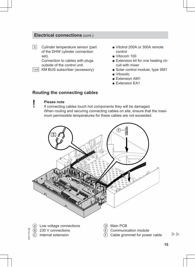
% Cylinder temperature sensor (partof the DHW cylinder connectionset).Connection to cables with plugsoutside of the control unit.
aVG KM BUS subscriber (accessory)
■ Vitotrol 200A or 300A remotecontrol
■ Vitocom 100■ Extension kit for one heating cir-
cuit with mixer■ Solar control module, type SM1■ Vitosolic■ Extension AM1■ Extension EA1
Routing the connecting cables
! Please noteIf connecting cables touch hot components they will be damaged. When routing and securing connecting cables on site, ensure that the maxi-mum permissible temperatures for these cables are not exceeded.
5
A Low voltage connectionsB 230 V connectionsC Internal extension
D Main PCBE Communication moduleF Cable grommet for power cable
Electrical connections (cont.)
5457
570
GB
16
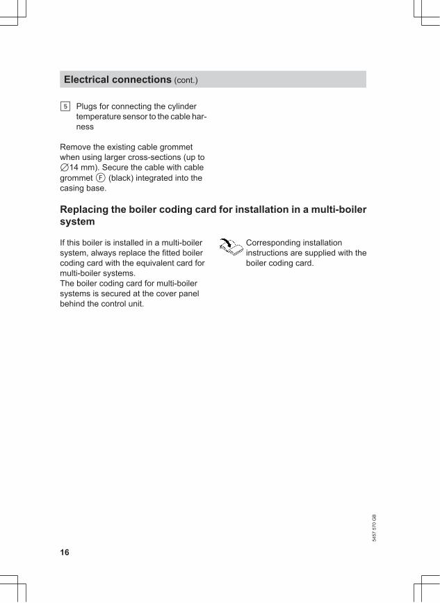
% Plugs for connecting the cylindertemperature sensor to the cable har-ness
Remove the existing cable grommetwhen using larger cross-sections (up to714 mm). Secure the cable with cablegrommet F (black) integrated into thecasing base.
Replacing the boiler coding card for installation in a multi-boilersystem
If this boiler is installed in a multi-boilersystem, always replace the fitted boilercoding card with the equivalent card formulti-boiler systems.The boiler coding card for multi-boilersystems is secured at the cover panelbehind the control unit.
Corresponding installationinstructions are supplied with theboiler coding card.
Electrical connections (cont.)
5457
570
GB
17
2.
1.
3. 2x
6.
5.
4.
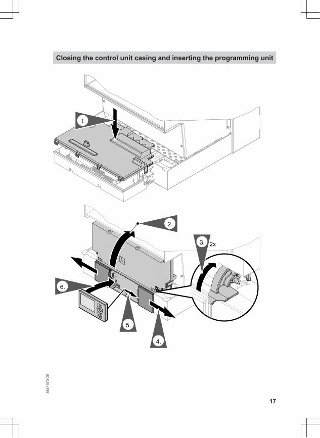
Closing the control unit casing and inserting the programming unit
5457
570
GB
18
Insert programming unit (packed sepa-rately) into the control unit support.
NoteThe programming unit can also be usedin a wall mounting base (accessory) nearthe boiler.
Wall mounting base installationinstructions
Closing the control unit casing and inserting… (cont.)
5457
570
GB
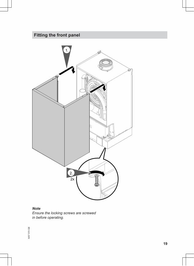
19
2.
2x2.
1.
NoteEnsure the locking screws are screwedin before operating.
Fitting the front panel54
57 5
70 G
B
20
For commissioning and adjust-ment, see service instructions.
Viessmann LimitedHortonwood 30, TelfordShropshire, TF1 7YP, GBTelephone: +44 1952 675000Fax: +44 1952 675040E-mail: [email protected]
Viessmann Werke GmbH&Co KGD-35107 AllendorfTelephone: +49 6452 70-0Fax: +49 6452 70-2780www.viessmann.com
5457
570
GB
Sub
ject
to te
chni
cal m
odifi
catio
ns.
Prin
ted
on e
nviro
nmen
tally
frie
ndly
,ch
lorin
e-fre
e bl
each
ed p
aper
Commissioning and adjustment