Embed Size (px)
Citation preview
Residential Energy Storage Unit6.4 EX Battery PackFor Photovoltaic Systems
Installation ManualApril 2015 | Edition 1
This manual describes how to safely install the RESU® 6.4 EX battery packfrom LG Chem.
Read this manual thoroughly before you attempt to install the product, andfollow the instructions carefully throughout the installation process.
If you are uncertain about any of the requirements, recommendations, or safetyprocedures described in this manual, contact LG Chem immediately for adviceand clarification.
NOTE
The information included in this document is accurate at the time of publi-cation. However, this product is subject to change without prior notice. Inaddition, the illustrations in this document are meant only to help explainsystem configuration concepts and installation instructions. The illustrateditems may differ from the actual items at the installation location.
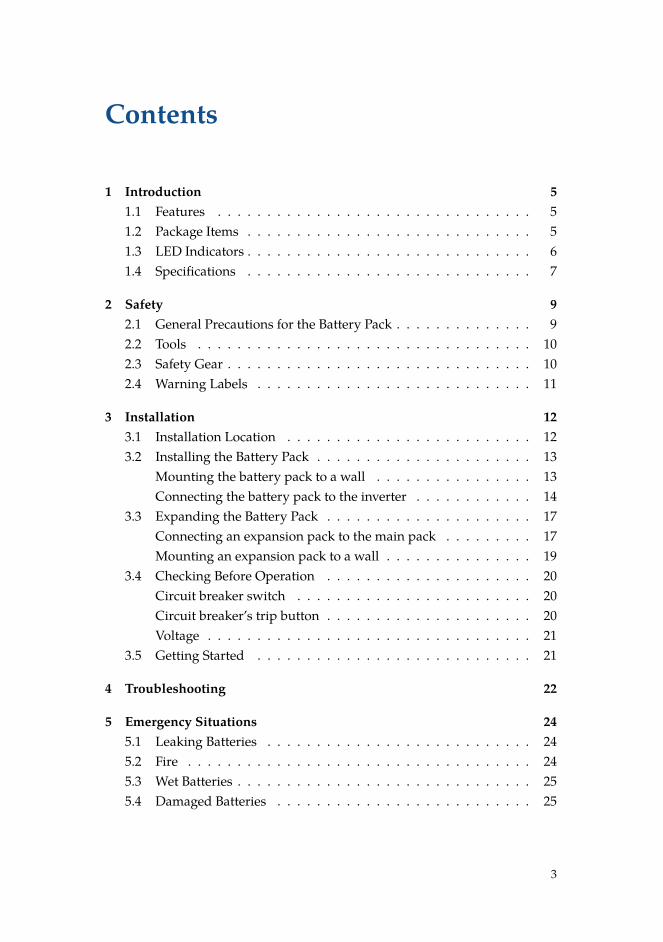
Contents
1 Introduction 51.1 Features . . . . . . . . . . . . . . . . . . . . . . . . . . . . . . . . 51.2 Package Items . . . . . . . . . . . . . . . . . . . . . . . . . . . . . 51.3 LED Indicators . . . . . . . . . . . . . . . . . . . . . . . . . . . . . 61.4 Specifications . . . . . . . . . . . . . . . . . . . . . . . . . . . . . 7
2 Safety 92.1 General Precautions for the Battery Pack . . . . . . . . . . . . . . 92.2 Tools . . . . . . . . . . . . . . . . . . . . . . . . . . . . . . . . . . 102.3 Safety Gear . . . . . . . . . . . . . . . . . . . . . . . . . . . . . . . 102.4 Warning Labels . . . . . . . . . . . . . . . . . . . . . . . . . . . . 11
3 Installation 123.1 Installation Location . . . . . . . . . . . . . . . . . . . . . . . . . 123.2 Installing the Battery Pack . . . . . . . . . . . . . . . . . . . . . . 13
Mounting the battery pack to a wall . . . . . . . . . . . . . . . . 13Connecting the battery pack to the inverter . . . . . . . . . . . . 14
3.3 Expanding the Battery Pack . . . . . . . . . . . . . . . . . . . . . 17Connecting an expansion pack to the main pack . . . . . . . . . 17Mounting an expansion pack to a wall . . . . . . . . . . . . . . . 19
3.4 Checking Before Operation . . . . . . . . . . . . . . . . . . . . . 20Circuit breaker switch . . . . . . . . . . . . . . . . . . . . . . . . 20Circuit breaker’s trip button . . . . . . . . . . . . . . . . . . . . . 20Voltage . . . . . . . . . . . . . . . . . . . . . . . . . . . . . . . . . 21
3.5 Getting Started . . . . . . . . . . . . . . . . . . . . . . . . . . . . 21
4 Troubleshooting 22
5 Emergency Situations 245.1 Leaking Batteries . . . . . . . . . . . . . . . . . . . . . . . . . . . 245.2 Fire . . . . . . . . . . . . . . . . . . . . . . . . . . . . . . . . . . . 245.3 Wet Batteries . . . . . . . . . . . . . . . . . . . . . . . . . . . . . . 255.4 Damaged Batteries . . . . . . . . . . . . . . . . . . . . . . . . . . 25
3
Contents
6 Warranty 266.1 Warranty Coverage . . . . . . . . . . . . . . . . . . . . . . . . . . 266.2 Limitation of Liability . . . . . . . . . . . . . . . . . . . . . . . . 26
A Technical Information 27
4
1 Introduction
1.1 FeaturesThe RESU® 6.4 EX battery pack has the following features:
Photovoltaic system: This battery pack is designed for household photovoltaicsystems.
Battery management system (BMS): The battery pack’s built-in BMS moni-tors its operation and prevents the battery from operating outside designlimitations. See Troubleshooting on page 22.
Expandability: This battery pack can be easily expanded by adding expan-sion battery packs. See Expanding the Battery Pack on page 17.
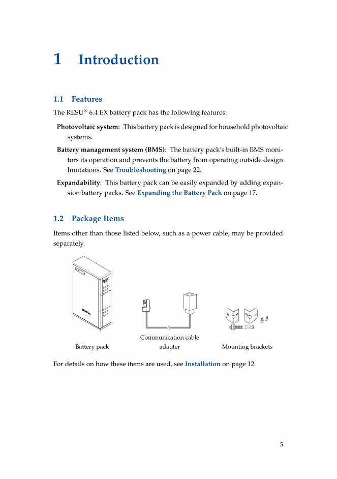
1.2 Package Items
Items other than those listed below, such as a power cable, may be providedseparately.
Status Charge / DischargeRESU 6.4
R
Battery packCommunication cable
adapter Mounting brackets
For details on how these items are used, see Installation on page 12.
5
Introduction
NOTE
A tag is attached to the gender changer side of the provided cable adapter.The tag is labeled as TYPE-S or TYPE-N. TYPE-S adapters are supposedto be used with SMA inverters, and TYPE-N ones are supposed to be usedwith Nedap inverters. If the wrong cable adapter is identified, contact LGChem or an authorized dealer.
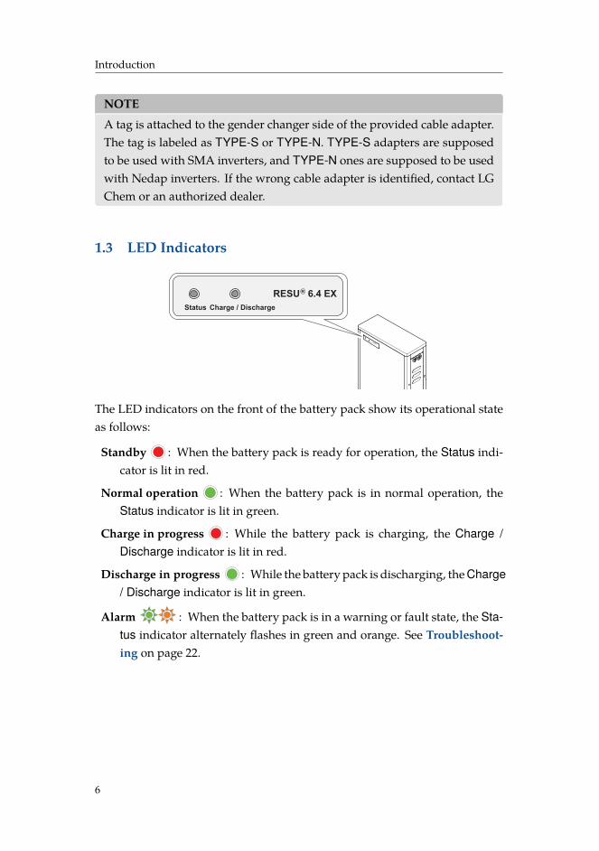
1.3 LED Indicators
Status Charge / DischargeRESU 6.4
R
Status Charge / Discharge
RESU 6.4 EXR
The LED indicators on the front of the battery pack show its operational stateas follows:
Standby : When the battery pack is ready for operation, the Status indi-cator is lit in red.
Normal operation : When the battery pack is in normal operation, theStatus indicator is lit in green.
Charge in progress : While the battery pack is charging, the Charge /Discharge indicator is lit in red.
Discharge in progress : While the battery pack is discharging, the Charge/ Discharge indicator is lit in green.
Alarm : When the battery pack is in a warning or fault state, the Sta-tus indicator alternately flashes in green and orange. See Troubleshoot-ing on page 22.
6
Introduction
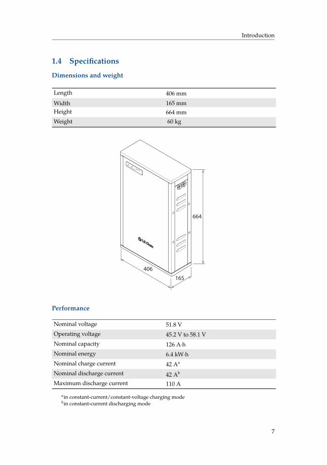
1.4 Specifications
Dimensions and weight
Length 406 mmWidth 165 mmHeight 664 mmWeight 60 kg
Status Charge / DischargeRESU 6.4
R
664
165
406
Performance
Nominal voltage 51.8 VOperating voltage 45.2 V to 58.1 VNominal capacity 126 A·hNominal energy 6.4 kW·hNominal charge current 42 Aa
Nominal discharge current 42 Ab
Maximum discharge current 110 A
ain constant-current/constant-voltage charging modebin constant-current discharging mode
7
Introduction
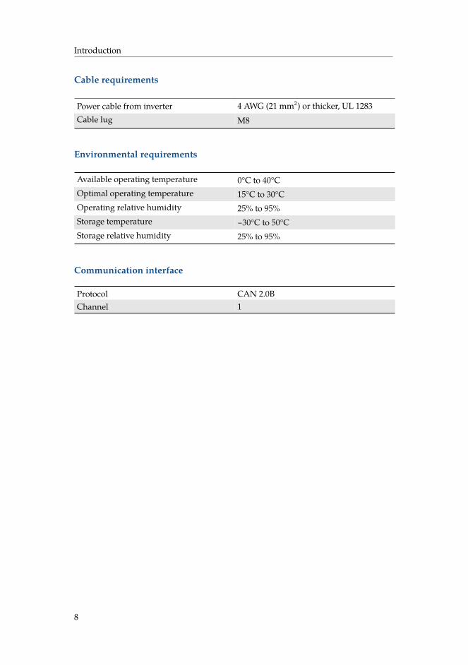
Cable requirements
Power cable from inverter 4 AWG (21 mm2) or thicker, UL 1283Cable lug M8
Environmental requirements
Available operating temperature 0°C to 40°COptimal operating temperature 15°C to 30°COperating relative humidity 25% to 95%Storage temperature −30°C to 50°CStorage relative humidity 25% to 95%
Communication interface
Protocol CAN 2.0BChannel 1
8
2 Safety
2.1 General Precautions for the Battery Pack
WARNING
Failure to observe the precautions described in this section can cause seri-ous injury to persons or damage to property.
Observe the following precautions:
• Risks of explosion
– Do not subject the battery pack to strong impacts.– Do not crush or puncture the battery pack.– Do not dispose of the battery pack in a fire.
• Risks of fire
– Do not expose the battery pack to temperatures in excess of 50°C.– Do not place the battery pack near a heat source such as a fireplace.– Do not expose the battery pack to direct sunlight.– Do not allow the battery connectors to touch conductive objects such as
wires.
• Risks of electric shock
– Do not disassemble the battery pack.– Do not touch the battery pack with wet hands.– Do not expose the battery pack to moisture or liquids.– Keep the battery pack away from children and animals.
• Risks of damage to the battery pack
– Do not allow the battery pack to come in contact with liquids.– Do not subject the battery pack to high pressures.– Do not place any objects on top of the battery pack.
9
Safety
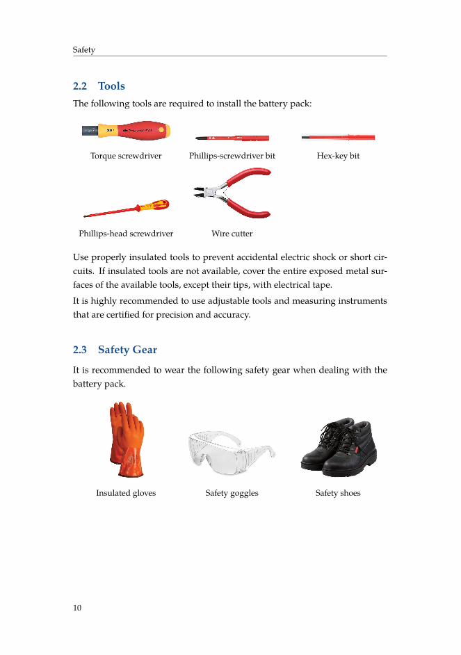
2.2 ToolsThe following tools are required to install the battery pack:
Torque screwdriver Phillips-screwdriver bit Hex-key bit
Phillips-head screwdriver Wire cutter
Use properly insulated tools to prevent accidental electric shock or short cir-cuits. If insulated tools are not available, cover the entire exposed metal sur-faces of the available tools, except their tips, with electrical tape.
It is highly recommended to use adjustable tools and measuring instrumentsthat are certified for precision and accuracy.
2.3 Safety Gear
It is recommended to wear the following safety gear when dealing with thebattery pack.
Insulated gloves Safety goggles Safety shoes
10
Safety
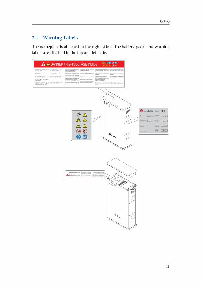
2.4 Warning Labels
The nameplate is attached to the right side of the battery pack, and warninglabels are attached to the top and left side.
Status Charge / DischargeRESU 6.4
R
ㆍGerät nicht in die Nähe offener Flammen stellen oder anzünden. Gefahr von Feuer oder Explosion!
ㆍHochheben durch Einzelpersonen kann zu Verletzungenführen! lmmer nur mit Assistenz das Gerät bewegenoder anheben.
ㆍGerät nicht Flussigkeiten oder Feuchtigkeit aussetzen!Gerät bei Flussigkeitsbenetzung nicht berühren!
ㆍGerät von Kindern oder Tieren fernhalten!
ㆍDas Sitzen und Platzieren von schweren Gegenständenauf die Batterieabdeckung ist zu unterlassen,umVerbiegungen und Brüche zu vermeiden.
ㆍDo not place near open flame or incinerate.It may lead to fire or explosion.
ㆍKeep the unit away from moisture or liquid.Do not touch or use if liquids was spilled on it.
ㆍSingle person lift could cause injury.Use assistance when moving or l i f t ing .
ㆍKeep out of reach of children or animals.
ㆍDo not sit or put heavy things on this Batterycover. It can cause deflection or fracture.
Abklemmung, Yerlegen oder Reparatur strikt verboten !(Vermeidung vonn Verletyungen, elektrischen Schocksoder Branden). Service-Arbeiten sind nur von autorisiertenlngenieuren gestattet.
Eigenmachtiges Laden oder Entladen verboten!Gefahr von Beschadigungen, elektrischen Schocksoder Branden!
Jegliche Beschadigungen durch Fall, Deformierung, Stoß, Anbohren, Schneiden sind verboten!Gefahr von Elektrolytaustritt oder Feuer!
Bei Versagen des Gerätes kann Elektrolyt austreten oder entflammbare Gase entstehen. In diesem Fall bitte direkt das LG Chem ESS QA Team unter +82 43 219 2720 kontaktieren.
ㆍBei Elektrolytaustritt ist der Kontakt mit demElektrolyten bzgl. Augen, Haut und Kleidung zuvermeiden. Bei Unfall betroffene Stellen sofort mit Wasser waschen und umgehend ärztliche Hilfeaufsuchen.
Do not disconnect, disassemble or repair to avoid injuries, electric shock or burns.Service by authorized engineers.
Do not charge or discharge arbitrari ly.It may lead to fault, electric shock or burns.
Do not damage the unit in such ways as drop, deform, impact, cut or spearing with a sharp object. It may cause electrolyte leakage or fire.
Breakdown of the unit may cause electrolyteleakage or flammable gas generation.In such case, please contact LG Chem ESS QA Team(Direct Contact Number:+82-43-219-2720) immediately.
When electrolyte leak out, avoid contact witheyes, skin or clothes. In event of accident,flush with water and get medical help immediately.
Status Charge / DischargeRESU 6.4
R
11
3 Installation
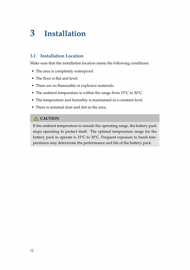
3.1 Installation LocationMake sure that the installation location meets the following conditions:
• The area is completely waterproof.
• The floor is flat and level.
• There are no flammable or explosive materials.
• The ambient temperature is within the range from 15°C to 30°C.
• The temperature and humidity is maintained at a constant level.
• There is minimal dust and dirt in the area.
CAUTION
If the ambient temperature is outside the operating range, the battery packstops operating to protect itself. The optimal temperature range for thebattery pack to operate is 15°C to 30°C. Frequent exposure to harsh tem-peratures may deteriorate the performance and life of the battery pack.
12
Installation
3.2 Installing the Battery Pack
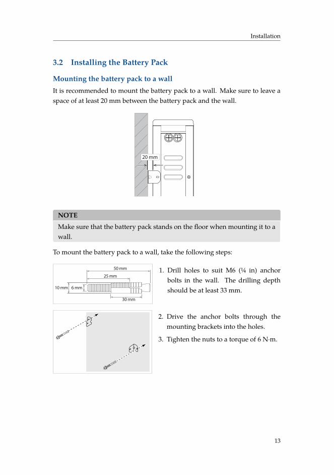
Mounting the battery pack to a wallIt is recommended to mount the battery pack to a wall. Make sure to leave aspace of at least 20 mm between the battery pack and the wall.
20 mm
NOTE
Make sure that the battery pack stands on the floor when mounting it to awall.
To mount the battery pack to a wall, take the following steps:
6 mm
30 mm
50 mm
25 mm
10 mm
1. Drill holes to suit M6 (¼ in) anchorbolts in the wall. The drilling depthshould be at least 33 mm.
2. Drive the anchor bolts through themounting brackets into the holes.
3. Tighten the nuts to a torque of 6 N·m.
13
Installation
Status Charge / DischargeRESU 6.4
R
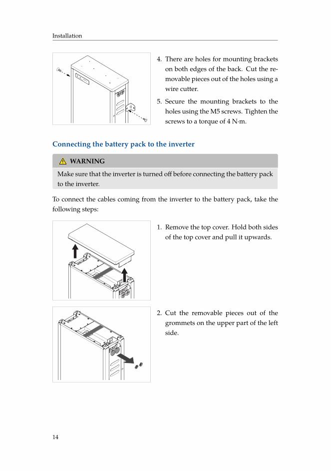
4. There are holes for mounting bracketson both edges of the back. Cut the re-movable pieces out of the holes using awire cutter.
5. Secure the mounting brackets to theholes using the M5 screws. Tighten thescrews to a torque of 4 N·m.
Connecting the battery pack to the inverter
WARNING
Make sure that the inverter is turned off before connecting the battery packto the inverter.
To connect the cables coming from the inverter to the battery pack, take thefollowing steps:
1. Remove the top cover. Hold both sidesof the top cover and pull it upwards.
2. Cut the removable pieces out of thegrommets on the upper part of the leftside.
14
Installation
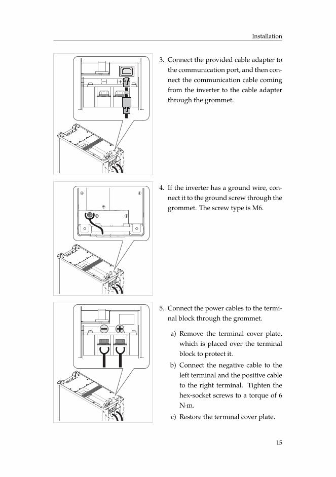
3. Connect the provided cable adapter tothe communication port, and then con-nect the communication cable comingfrom the inverter to the cable adapterthrough the grommet.
4. If the inverter has a ground wire, con-nect it to the ground screw through thegrommet. The screw type is M6.
5. Connect the power cables to the termi-nal block through the grommet.
a) Remove the terminal cover plate,which is placed over the terminalblock to protect it.
b) Connect the negative cable to theleft terminal and the positive cableto the right terminal. Tighten thehex-socket screws to a torque of 6N·m.
c) Restore the terminal cover plate.
15
Installation
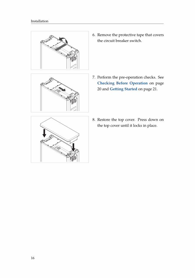
6. Remove the protective tape that coversthe circuit breaker switch.
7. Perform the pre-operation checks. SeeChecking Before Operation on page20 and Getting Started on page 21.
8. Restore the top cover. Press down onthe top cover until it locks in place.
16
Installation
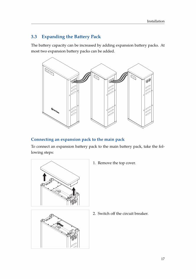
3.3 Expanding the Battery Pack
The battery capacity can be increased by adding expansion battery packs. Atmost two expansion battery packs can be added.
Status Charge / DischargeRESU 6.4
R
Status Charge / Discharge
Status Charge / Discharge
Connecting an expansion pack to the main packTo connect an expansion battery pack to the main battery pack, take the fol-lowing steps:
1. Remove the top cover.
2. Switch off the circuit breaker.
17
Installation
Status Charge / DischargeRESU 6.4
R
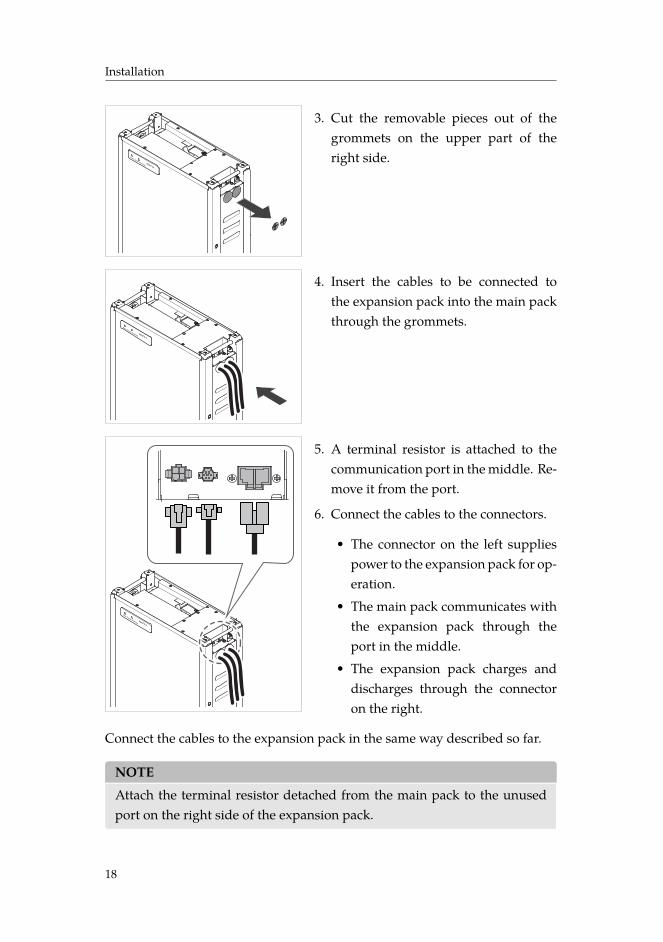
3. Cut the removable pieces out of thegrommets on the upper part of theright side.
Status Charge / DischargeRESU 6.4
R
4. Insert the cables to be connected tothe expansion pack into the main packthrough the grommets.
Status Charge / DischargeRESU 6.4
R
5. A terminal resistor is attached to thecommunication port in the middle. Re-move it from the port.
6. Connect the cables to the connectors.
• The connector on the left suppliespower to the expansion pack for op-eration.
• The main pack communicates withthe expansion pack through theport in the middle.
• The expansion pack charges anddischarges through the connectoron the right.
Connect the cables to the expansion pack in the same way described so far.
NOTE
Attach the terminal resistor detached from the main pack to the unusedport on the right side of the expansion pack.
18
Installation
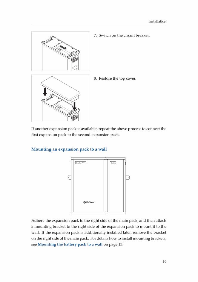
7. Switch on the circuit breaker.
8. Restore the top cover.
If another expansion pack is available, repeat the above process to connect thefirst expansion pack to the second expansion pack.
Mounting an expansion pack to a wall
Status Charge / Discharge
RESU 6.4R
Status Charge / Discharge
Adhere the expansion pack to the right side of the main pack, and then attacha mounting bracket to the right side of the expansion pack to mount it to thewall. If the expansion pack is additionally installed later, remove the bracketon the right side of the main pack. For details how to install mounting brackets,see Mounting the battery pack to a wall on page 13.
19
Installation
3.4 Checking Before Operation
There are things that need to be checked before starting the battery pack toensure that it has no defects.
WARNING
Make sure that the inverter is turned off while checking the battery pack.
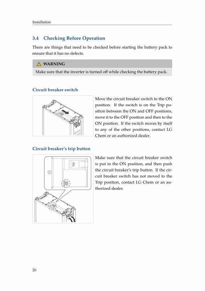
Circuit breaker switch
Move the circuit breaker switch to the ONposition. If the switch is on the Trip po-sition between the ON and OFF positions,move it to the OFF position and then to theON position. If the switch moves by itselfto any of the other positions, contact LGChem or an authorized dealer.
Circuit breaker’s trip button
Make sure that the circuit breaker switchis put in the ON position, and then pushthe circuit breaker’s trip button. If the cir-cuit breaker switch has not moved to theTrip position, contact LG Chem or an au-thorized dealer.
20
Installation
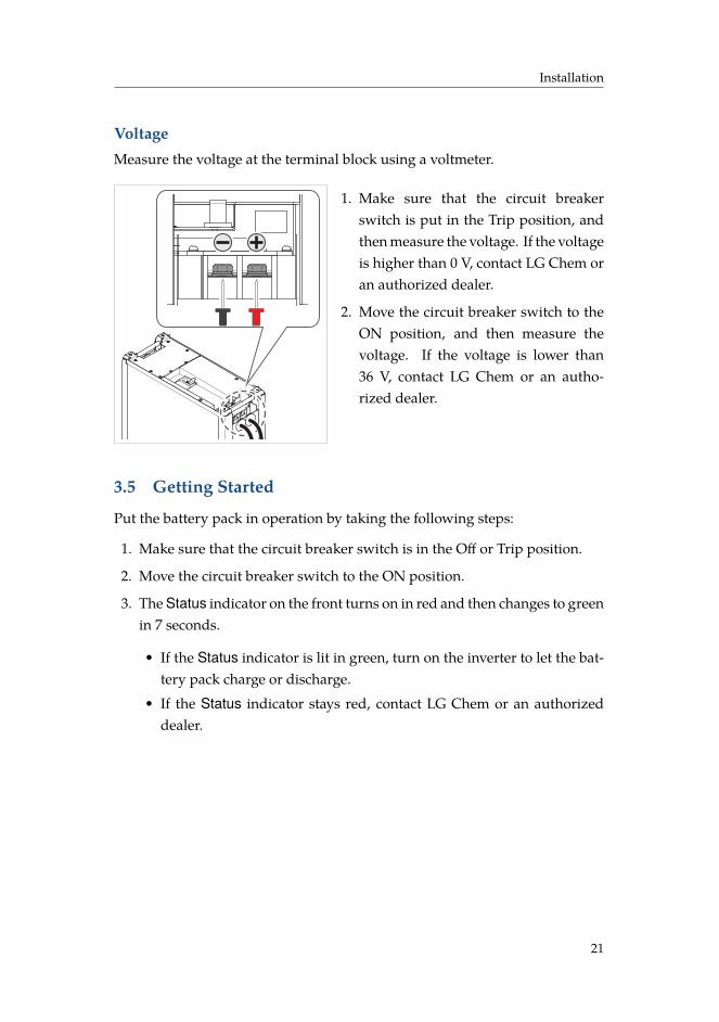
VoltageMeasure the voltage at the terminal block using a voltmeter.
1. Make sure that the circuit breakerswitch is put in the Trip position, andthen measure the voltage. If the voltageis higher than 0 V, contact LG Chem oran authorized dealer.
2. Move the circuit breaker switch to theON position, and then measure thevoltage. If the voltage is lower than36 V, contact LG Chem or an autho-rized dealer.
3.5 Getting Started
Put the battery pack in operation by taking the following steps:
1. Make sure that the circuit breaker switch is in the Off or Trip position.
2. Move the circuit breaker switch to the ON position.
3. The Status indicator on the front turns on in red and then changes to greenin 7 seconds.
• If the Status indicator is lit in green, turn on the inverter to let the bat-tery pack charge or discharge.
• If the Status indicator stays red, contact LG Chem or an authorizeddealer.
21
4 Troubleshooting
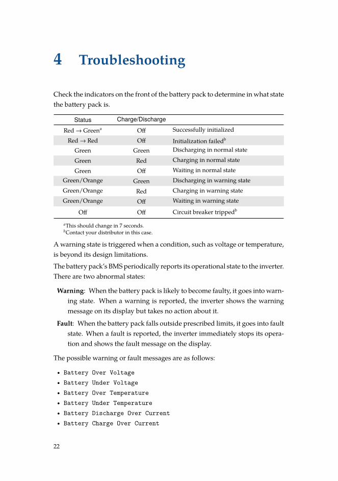
Check the indicators on the front of the battery pack to determine in what statethe battery pack is.
Status Charge/Discharge
Red → Greena Off Successfully initialized
Red → Red Off Initialization failedb
Green Green Discharging in normal state
Green Red Charging in normal state
Green Off Waiting in normal stateGreen/Orange Green Discharging in warning stateGreen/Orange Red Charging in warning stateGreen/Orange Off Waiting in warning state
Off Off Circuit breaker trippedb
aThis should change in 7 seconds.bContact your distributor in this case.
A warning state is triggered when a condition, such as voltage or temperature,is beyond its design limitations.
The battery pack’s BMS periodically reports its operational state to the inverter.There are two abnormal states:
Warning: When the battery pack is likely to become faulty, it goes into warn-ing state. When a warning is reported, the inverter shows the warningmessage on its display but takes no action about it.
Fault: When the battery pack falls outside prescribed limits, it goes into faultstate. When a fault is reported, the inverter immediately stops its opera-tion and shows the fault message on the display.
The possible warning or fault messages are as follows:
• Battery Over Voltage• Battery Under Voltage• Battery Over Temperature• Battery Under Temperature• Battery Discharge Over Current• Battery Charge Over Current
22
Troubleshooting
• BMS Internal Communication• Battery Cell Voltage Imbalance
An abnormal state is released when the battery pack recovers its normal con-dition.
NOTE
For a serious fault, if no proper corrective actions are taken by the inverter,the battery pack’s circuit breaker automatically trips to protect itself. Forexample, if the Status indicator stays red for more than 5 minutes, the cir-cuit breaker trips. Use the monitoring software on the inverter to identifywhat caused the fault.
23
5 Emergency Situations
The RESU 6.4 EX battery pack comprises multiple batteries that are designed toprevent hazards resulting from failures. However, LG Chem cannot guaranteetheir absolute safety.
5.1 Leaking Batteries
If the battery pack leaks electrolyte, avoid contact with the leaking liquid orgas. If one is exposed to the leaked substance, immediately perform the actionsdescribed below.
Inhalation: Evacuate the contaminated area, and seek medical attention.
Contact with eyes: Rinse eyes with flowing water for 15 minutes, and seekmedical attention.
Contact with skin: Wash the affected area thoroughly with soap and water,and seek medical attention.
Ingestion: Induce vomiting, and seek medical attention.
5.2 FireIn case of fires, make sure that the following equipment is available near thebattery pack.
• SCBA (self-contained breathing apparatus) and protective gear in compli-ance with the Directive on Personal Protective Equipment 89/686/EEC
• Novec 1230, FM-200, or dioxide extinguisher.
NOTE
ABC extinguishers are not effective when the battery pack is on fire.
Batteries may explode when heated above 150°C. If possible, move the batterypack to a safe area before it catches fire.
24
Emergency Situations
5.3 Wet BatteriesIf the battery pack is wet or submerged in water, do not let people access it,and then contact LG Chem or an authorized dealer for technical support.
5.4 Damaged Batteries
Damaged batteries are dangerous and must be handled with the utmost care.They are not fit for use and may pose a danger to people or property.
If the battery pack seems to be damaged, pack it in its original container, andthen return it to LG Chem or an authorized dealer.
NOTE
Damaged batteries may leak electrolyte or produce flammable gas. If sucha damage occurs, immediately contact LG Chem at +82-43-219-2720.
25
6 Warranty
6.1 Warranty Coverage
LG Chem protects this product under warranty when this product is installedand used as detailed in this manual. Violating the installation procedure orusing this product in any way not described in this manual immediately voidsall warranties on this product.
6.2 Limitation of Liability
LG Chem does not provide warranty coverage or assume any liability for director indirect damages or defects that result from the following causes:
• Transportation or storage
• Incorrect installation
• Operating the product in an inappropriate environment
• Incorrect or inappropriate operation
• Insufficient ventilation
• Failure to adhere to safety warnings or instructions
• Repairs or modifications performed by unauthorized personnel
• Rectifier failure or overcurrent.
• Force majeure events
• External influences, such as unusual physical or electrical stress.
• Use of a rectifier that fails to meet the requirements.
26
A Technical Information
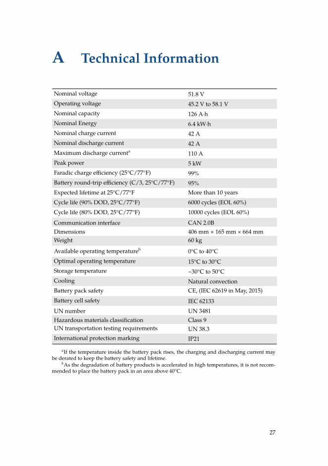
Nominal voltage 51.8 VOperating voltage 45.2 V to 58.1 VNominal capacity 126 A·hNominal Energy 6.4 kW·hNominal charge current 42 ANominal discharge current 42 AMaximum discharge currenta 110 APeak power 5 kWFaradic charge efficiency (25°C/77°F) 99%Battery round-trip efficiency (C/3, 25°C/77°F) 95%Expected lifetime at 25°C/77°F More than 10 yearsCycle life (90% DOD, 25°C/77°F) 6000 cycles (EOL 60%)Cycle life (80% DOD, 25°C/77°F) 10000 cycles (EOL 60%)
Communication interface CAN 2.0BDimensions 406 mm × 165 mm × 664 mmWeight 60 kg
Available operating temperatureb 0°C to 40°COptimal operating temperature 15°C to 30°CStorage temperature −30°C to 50°CCooling Natural convectionBattery pack safety CE, (IEC 62619 in May, 2015)Battery cell safety IEC 62133UN number UN 3481Hazardous materials classification Class 9UN transportation testing requirements UN 38.3International protection marking IP21
aIf the temperature inside the battery pack rises, the charging and discharging current maybe derated to keep the battery safety and lifetime.
bAs the degradation of battery products is accelerated in high temperatures, it is not recom-mended to place the battery pack in an area above 40°C.
27

Keep this manual for later use.
LG ChemLG Twin Tower, 128 Yeoui-daero Yeongdeungpo-gu Seoul150-721, Korea