Embed Size (px)
Citation preview
Installation Instructionsfor Stacked Washer/Dryers
Original InstructionsKeep These Instructions for Future Reference.CAUTION: Read the instructions before using the machine.(If this machine changes ownership, this manual must accompany machine.)
www.speedqueen.com Part No. 804671ENR4August 2017

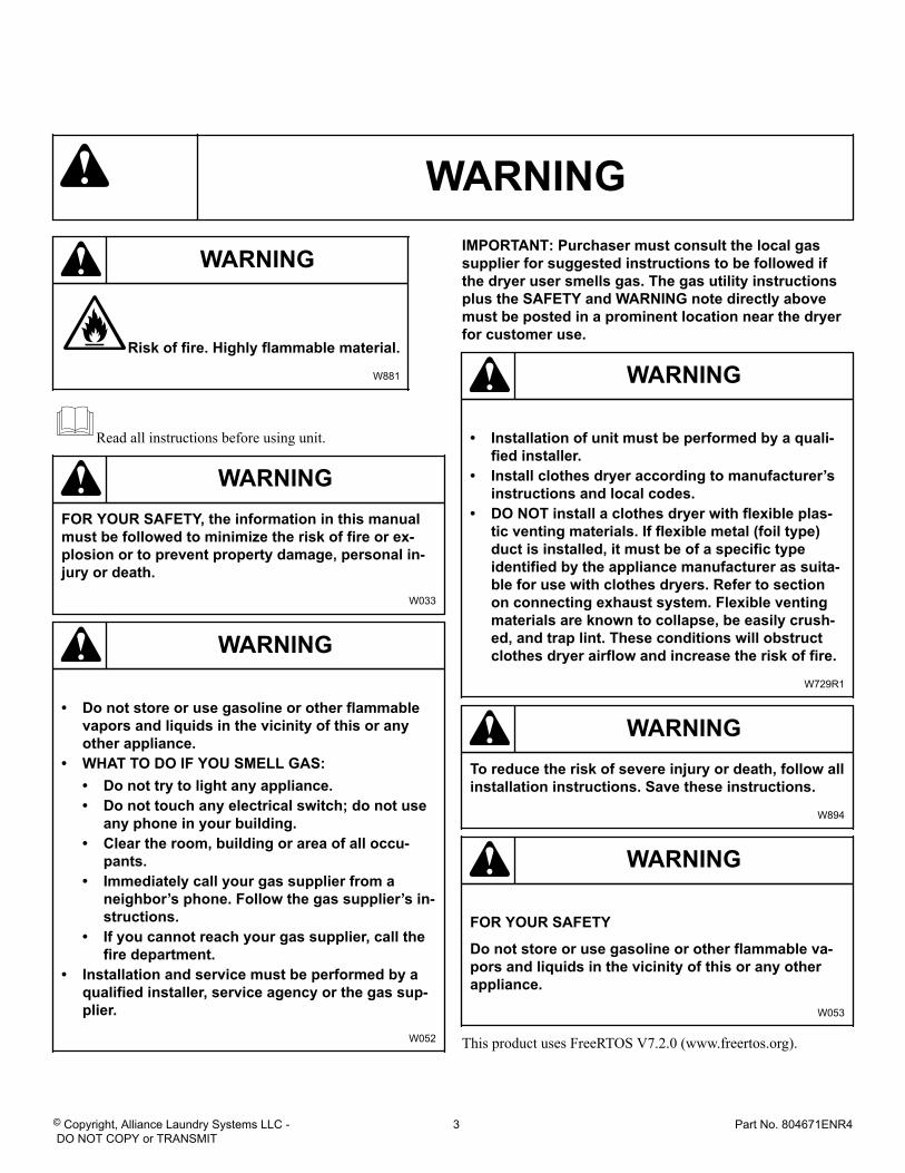
WARNING
WARNING
Risk of fire. Highly flammable material.
W881
Read all instructions before using unit.
WARNINGFOR YOUR SAFETY, the information in this manualmust be followed to minimize the risk of fire or ex-plosion or to prevent property damage, personal in-jury or death.
W033
WARNING
• Do not store or use gasoline or other flammablevapors and liquids in the vicinity of this or anyother appliance.
• WHAT TO DO IF YOU SMELL GAS:• Do not try to light any appliance.• Do not touch any electrical switch; do not use
any phone in your building.• Clear the room, building or area of all occu-
pants.• Immediately call your gas supplier from a
neighbor’s phone. Follow the gas supplier’s in-structions.
• If you cannot reach your gas supplier, call thefire department.
• Installation and service must be performed by aqualified installer, service agency or the gas sup-plier.
W052
IMPORTANT: Purchaser must consult the local gassupplier for suggested instructions to be followed ifthe dryer user smells gas. The gas utility instructionsplus the SAFETY and WARNING note directly abovemust be posted in a prominent location near the dryerfor customer use.
WARNING
• Installation of unit must be performed by a quali-fied installer.
• Install clothes dryer according to manufacturer’sinstructions and local codes.
• DO NOT install a clothes dryer with flexible plas-tic venting materials. If flexible metal (foil type)duct is installed, it must be of a specific typeidentified by the appliance manufacturer as suita-ble for use with clothes dryers. Refer to sectionon connecting exhaust system. Flexible ventingmaterials are known to collapse, be easily crush-ed, and trap lint. These conditions will obstructclothes dryer airflow and increase the risk of fire.
W729R1
WARNINGTo reduce the risk of severe injury or death, follow allinstallation instructions. Save these instructions.
W894
WARNING
FOR YOUR SAFETY
Do not store or use gasoline or other flammable va-pors and liquids in the vicinity of this or any otherappliance.
W053
This product uses FreeRTOS V7.2.0 (www.freertos.org).
© Copyright, Alliance Laundry Systems LLC - DO NOT COPY or TRANSMIT
3 Part No. 804671ENR4
The following information applies to the state of Massachusetts,USA.
• This appliance can only be installed by a Massachusetts li-censed plumber or gas fitter.
• This appliance must be installed with a 36 inch [910 mm]long flexible gas connector.
• A “T-Handle” type gas shut-off valve must be installed in thegas supply line to this appliance.
• This appliance must not be installed in a bedroom or bath-room.
© Copyright, Alliance Laundry Systems LLC - DO NOT COPY or TRANSMIT
4 Part No. 804671ENR4
Table of Contents
Dimensions............................................................................................. 6
Installation............................................................................................. 9Before You Start............................................................................................. 9
Tools..........................................................................................................9Parts Included............................................................................................. 9Removing Dryer......................................................................................... 9Reassembling Dryer.................................................................................... 9Order of Installation Steps............................................................................9
Position Unit Near Installation Area............................................................... 10Remove Shipping Materials........................................................................... 10Connect Fill Hoses........................................................................................11
Water Supply Requirements........................................................................11Connecting Hoses......................................................................................11Risers.......................................................................................................12
Connect Drain Hose to Drain Receptacle.........................................................12Standpipe Installation................................................................................ 12Wall Installation........................................................................................ 13Laundry Tub Installation............................................................................ 13
Gas Dryers - Connect Gas Supply Pipe........................................................... 13Electric Dryer Only - Connect Electrical Plug..................................................15
Earth/Ground Information.......................................................................... 15Connecting Power Cord with Three-Wire Plug.............................................16Connecting Power Cord with Four-Wire Plug.............................................. 18
Connect Dryer Exhaust System...................................................................... 20Exhaust Direction......................................................................................21Exhaust System.........................................................................................21
Position and Level the Unit............................................................................21Wipe Out Inside of Washer and Dryer Drums.................................................. 23Plug In the Washer and Dryer.........................................................................23
Electric Dryer........................................................................................... 23Gas Dryer................................................................................................. 23Washer..................................................................................................... 25
Check Installation......................................................................................... 26Check Heat Source........................................................................................26
Electric Dryers.......................................................................................... 26Gas Dryers................................................................................................26
Installer Checklist.................................................................................28
© Copyright 2017, Alliance Laundry Systems LLCAll rights reserved. No part of the contents of this book may be reproduced or transmitted in any form or by any means without the expressedwritten consent of the publisher.
© Copyright, Alliance Laundry Systems LLC - DO NOT COPY or TRANSMIT
5 Part No. 804671ENR4
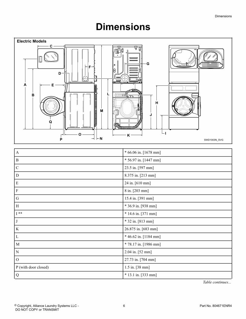
DimensionsElectric Models
SWD1003N_SVG
O
Q
P N
M
L
K
J
I
H
GF
E
D
C
B
A
A * 66.06 in. [1678 mm]
B * 56.97 in. [1447 mm]
C 23.5 in. [597 mm]
D 8.375 in. [213 mm]
E 24 in. [610 mm]
F 8 in. [203 mm]
G 15.4 in. [391 mm]
H * 36.9 in. [938 mm]
I ** * 14.6 in. [371 mm]
J * 32 in. [813 mm]
K 26.875 in. [683 mm]
L * 46.62 in. [1184 mm]
M * 78.17 in. [1986 mm]
N 2.04 in. [52 mm]
O 27.73 in. [704 mm]
P (with door closed) 1.5 in. [38 mm]
Q * 13.1 in. [333 mm]
Table continues...
Dimensions
© Copyright, Alliance Laundry Systems LLC - DO NOT COPY or TRANSMIT
6 Part No. 804671ENR4
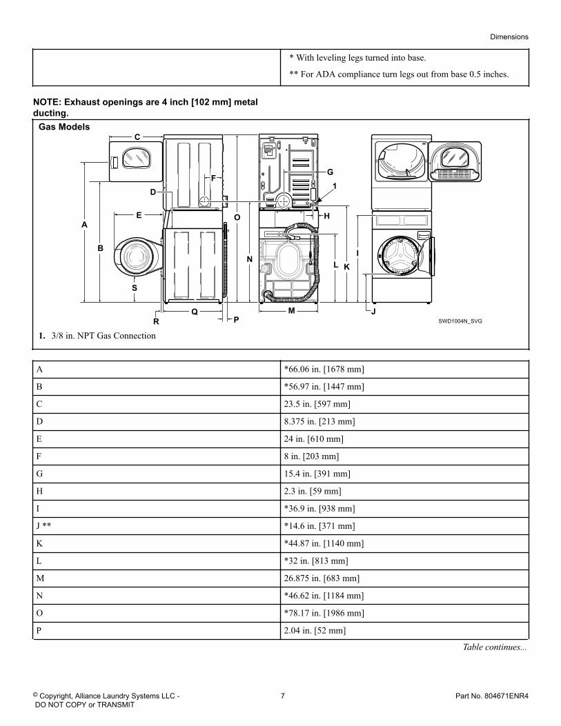
* With leveling legs turned into base.
** For ADA compliance turn legs out from base 0.5 inches.
NOTE: Exhaust openings are 4 inch [102 mm] metalducting.
Gas Models
SWD1004N_SVG
I
H
GF
E
D
C
B
A
K
M
L
JQR
O
S
P
N
1
1. 3/8 in. NPT Gas Connection
A *66.06 in. [1678 mm]
B *56.97 in. [1447 mm]
C 23.5 in. [597 mm]
D 8.375 in. [213 mm]
E 24 in. [610 mm]
F 8 in. [203 mm]
G 15.4 in. [391 mm]
H 2.3 in. [59 mm]
I *36.9 in. [938 mm]
J ** *14.6 in. [371 mm]
K *44.87 in. [1140 mm]
L *32 in. [813 mm]
M 26.875 in. [683 mm]
N *46.62 in. [1184 mm]
O *78.17 in. [1986 mm]
P 2.04 in. [52 mm]
Table continues...
Dimensions
© Copyright, Alliance Laundry Systems LLC - DO NOT COPY or TRANSMIT
7 Part No. 804671ENR4
Q 27.73 in. [704 mm]
R (with door closed) 1.5 in. [38 mm]
S *13.1 in. [333 mm]
* With leveling legs turned into base.
** For ADA compliance turn legs out from base 0.5 inches.
NOTE: Exhaust openings are 4 inch [102 mm] metalducting.
Dimensions
© Copyright, Alliance Laundry Systems LLC - DO NOT COPY or TRANSMIT
8 Part No. 804671ENR4
Installation Before You Start Tools
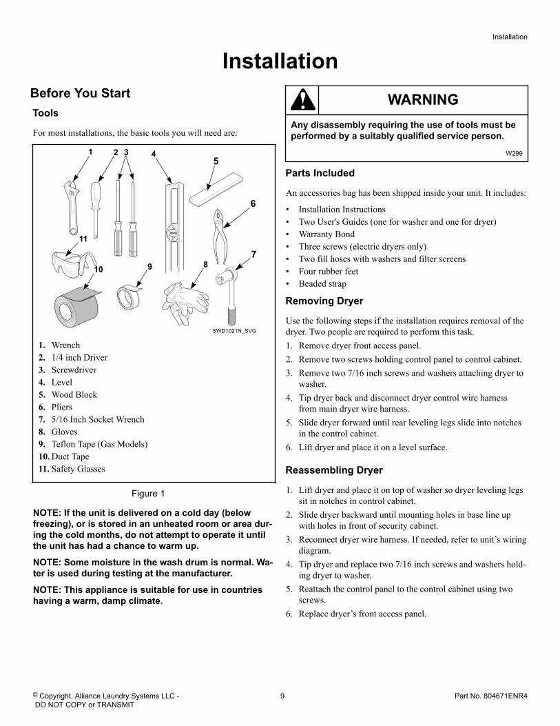
For most installations, the basic tools you will need are:
SWD1021N_SVG
11
10 9 8
4321
6
7
5
1. Wrench2. 1/4 inch Driver3. Screwdriver4. Level5. Wood Block6. Pliers7. 5/16 Inch Socket Wrench8. Gloves9. Teflon Tape (Gas Models)10. Duct Tape11. Safety Glasses
Figure 1
NOTE: If the unit is delivered on a cold day (belowfreezing), or is stored in an unheated room or area dur-ing the cold months, do not attempt to operate it untilthe unit has had a chance to warm up.
NOTE: Some moisture in the wash drum is normal. Wa-ter is used during testing at the manufacturer.
NOTE: This appliance is suitable for use in countrieshaving a warm, damp climate.
WARNINGAny disassembly requiring the use of tools must beperformed by a suitably qualified service person.
W299
Parts Included
An accessories bag has been shipped inside your unit. It includes:
• Installation Instructions• Two User's Guides (one for washer and one for dryer)• Warranty Bond• Three screws (electric dryers only)• Two fill hoses with washers and filter screens• Four rubber feet• Beaded strap
Removing Dryer
Use the following steps if the installation requires removal of thedryer. Two people are required to perform this task.1. Remove dryer front access panel.2. Remove two screws holding control panel to control cabinet.3. Remove two 7/16 inch screws and washers attaching dryer to
washer.4. Tip dryer back and disconnect dryer control wire harness
from main dryer wire harness.5. Slide dryer forward until rear leveling legs slide into notches
in the control cabinet.6. Lift dryer and place it on a level surface.
Reassembling Dryer
1. Lift dryer and place it on top of washer so dryer leveling legssit in notches in control cabinet.
2. Slide dryer backward until mounting holes in base line upwith holes in front of security cabinet.
3. Reconnect dryer wire harness. If needed, refer to unit’s wiringdiagram.
4. Tip dryer and replace two 7/16 inch screws and washers hold-ing dryer to washer.
5. Reattach the control panel to the control cabinet using twoscrews.
6. Replace dryer’s front access panel.
Installation
© Copyright, Alliance Laundry Systems LLC - DO NOT COPY or TRANSMIT
9 Part No. 804671ENR4
Order of Installation Steps
The proper order of steps must be followed to ensure correct in-stallation. Refer to the list below when installing your unit.1. Position unit near area of installation.2. Remove the shipping materials.3. Connect the fill hoses.4. Connect the drain hose to the drain receptacle.5. For gas models only, connect the gas supply pipe. Check for
gas leaks.6. For electric models only, connect the electrical cord.7. Connect dryer to exhaust system.8. Position and level the unit.9. Wipe out inside of washer and dryer drums.10. Plug in the washer and dryer.11. Check installation.12. Start and run the dryer in a heat setting to verify dryer is heat-
ing.
Position Unit Near Installation AreaMove unit so that it is within 4 feet [1.2 meters] of the desiredarea of installation.
CAUTIONWasher and dryer are not designed to be operated asseparated, side-by-side units.
W187
The stack washer/dryer must be installed on a ground or base-ment floor, preferably concrete. If the flooring is wood construc-tion, the flooring must meet a static load rating of 125 poundsand a maximum dynamic load rating of 170 pounds per foot. Ifthe existing floor does not meet the dynamic load rating, the floormust be re-enforced from below to meet the specification (maxi-mum span = 16 feet, 2x10 joists, 16 inches on center, 1 inch subfloor).
The stack washer/dryer must be installed on a smooth, non-slipsurface. Un-level tile and extremely slippery surfaces should beavoided. Do not install the washer on carpeting, soft tile or otherweakly supported structures.
Failure to meet the minimum floor load and surface requirementsor installing the products on above ground floors can create dif-ferent levels of vibration or movement that may appear like serv-ice is required. Speed Queen will not cover scheduled repair serv-ices where the installation requirements are not per specifica-tions, nor can products be returned to the authorized dealer inthese cases.
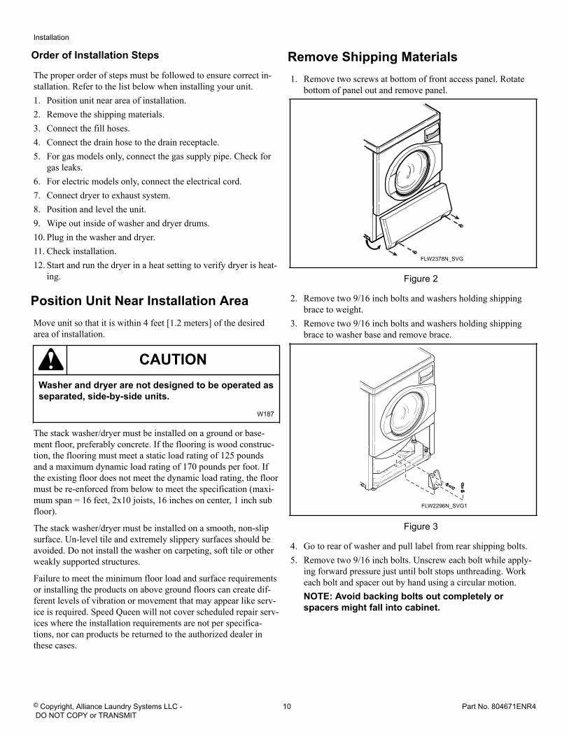
Remove Shipping Materials1. Remove two screws at bottom of front access panel. Rotate
bottom of panel out and remove panel.
FLW2378N_SVG
Figure 2
2. Remove two 9/16 inch bolts and washers holding shippingbrace to weight.
3. Remove two 9/16 inch bolts and washers holding shippingbrace to washer base and remove brace.
FLW2296N_SVG1
Figure 3
4. Go to rear of washer and pull label from rear shipping bolts.5. Remove two 9/16 inch bolts. Unscrew each bolt while apply-
ing forward pressure just until bolt stops unthreading. Workeach bolt and spacer out by hand using a circular motion.NOTE: Avoid backing bolts out completely orspacers might fall into cabinet.
Installation
© Copyright, Alliance Laundry Systems LLC - DO NOT COPY or TRANSMIT
10 Part No. 804671ENR4
FLW2297N_SVG1
Figure 4
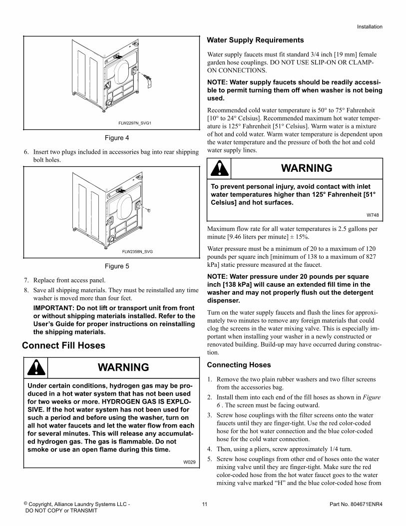
6. Insert two plugs included in accessories bag into rear shippingbolt holes.
FLW2358N_SVG
Figure 5
7. Replace front access panel.8. Save all shipping materials. They must be reinstalled any time
washer is moved more than four feet.IMPORTANT: Do not lift or transport unit from frontor without shipping materials installed. Refer to theUser’s Guide for proper instructions on reinstallingthe shipping materials.
Connect Fill Hoses
WARNINGUnder certain conditions, hydrogen gas may be pro-duced in a hot water system that has not been usedfor two weeks or more. HYDROGEN GAS IS EXPLO-SIVE. If the hot water system has not been used forsuch a period and before using the washer, turn onall hot water faucets and let the water flow from eachfor several minutes. This will release any accumulat-ed hydrogen gas. The gas is flammable. Do notsmoke or use an open flame during this time.
W029
Water Supply Requirements
Water supply faucets must fit standard 3/4 inch [19 mm] femalegarden hose couplings. DO NOT USE SLIP-ON OR CLAMP-ON CONNECTIONS.
NOTE: Water supply faucets should be readily accessi-ble to permit turning them off when washer is not beingused.
Recommended cold water temperature is 50° to 75° Fahrenheit[10° to 24° Celsius]. Recommended maximum hot water temper-ature is 125° Fahrenheit [51° Celsius]. Warm water is a mixtureof hot and cold water. Warm water temperature is dependent uponthe water temperature and the pressure of both the hot and coldwater supply lines.
WARNINGTo prevent personal injury, avoid contact with inletwater temperatures higher than 125° Fahrenheit [51°Celsius] and hot surfaces.
W748
Maximum flow rate for all water temperatures is 2.5 gallons perminute [9.46 liters per minute] ± 15%.
Water pressure must be a minimum of 20 to a maximum of 120pounds per square inch [minimum of 138 to a maximum of 827kPa] static pressure measured at the faucet.
NOTE: Water pressure under 20 pounds per squareinch [138 kPa] will cause an extended fill time in thewasher and may not properly flush out the detergentdispenser.
Turn on the water supply faucets and flush the lines for approxi-mately two minutes to remove any foreign materials that couldclog the screens in the water mixing valve. This is especially im-portant when installing your washer in a newly constructed orrenovated building. Build-up may have occurred during construc-tion.
Connecting Hoses
1. Remove the two plain rubber washers and two filter screensfrom the accessories bag.
2. Install them into each end of the fill hoses as shown in Figure6 . The screen must be facing outward.
3. Screw hose couplings with the filter screens onto the waterfaucets until they are finger-tight. Use the red color-codedhose for the hot water connection and the blue color-codedhose for the cold water connection.
4. Then, using a pliers, screw approximately 1/4 turn.5. Screw hose couplings from other end of hoses onto the water
mixing valve until they are finger-tight. Make sure the redcolor-coded hose from the hot water faucet goes to the watermixing valve marked “H” and the blue color-coded hose from
Installation
© Copyright, Alliance Laundry Systems LLC - DO NOT COPY or TRANSMIT
11 Part No. 804671ENR4
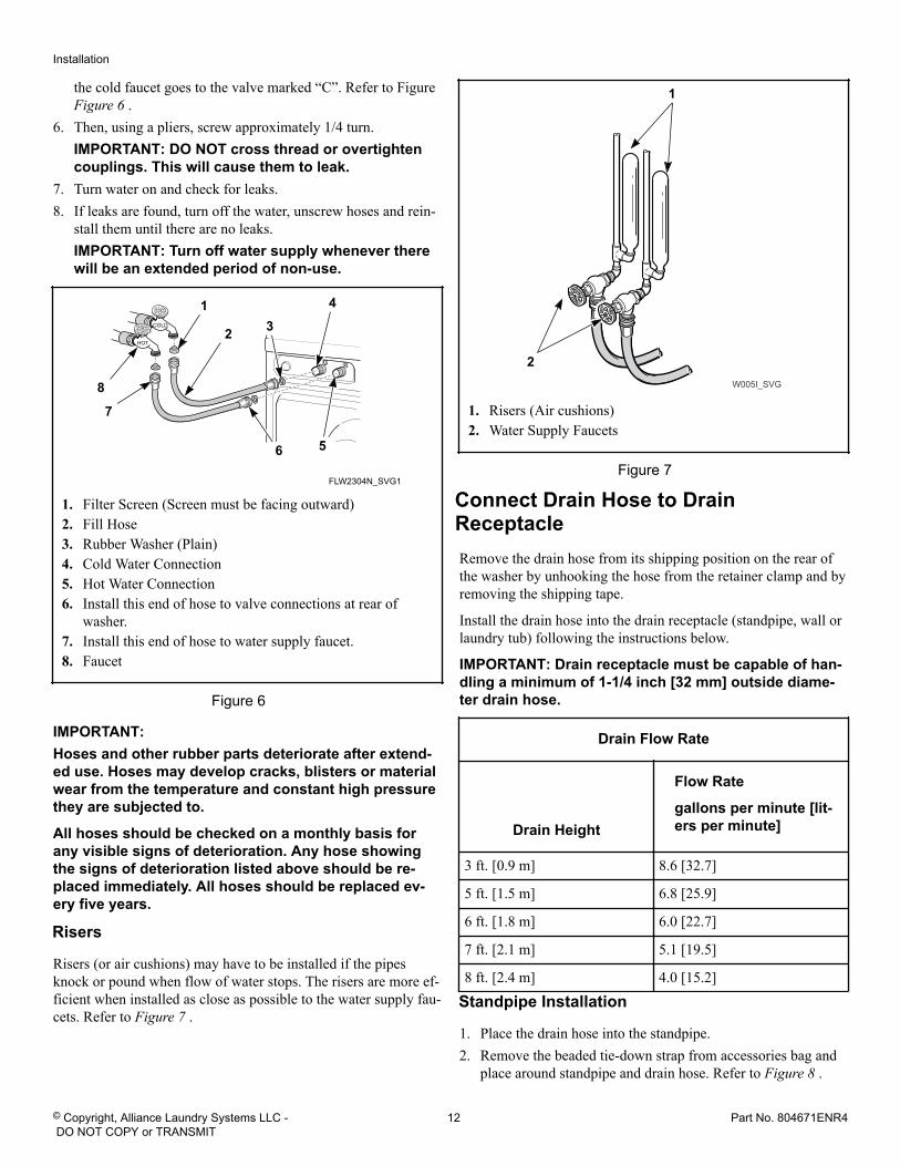
the cold faucet goes to the valve marked “C”. Refer to Figure Figure 6 .
6. Then, using a pliers, screw approximately 1/4 turn.IMPORTANT: DO NOT cross thread or overtightencouplings. This will cause them to leak.
7. Turn water on and check for leaks.8. If leaks are found, turn off the water, unscrew hoses and rein-
stall them until there are no leaks.IMPORTANT: Turn off water supply whenever therewill be an extended period of non-use.
FLW2304N_SVG1
COLD
HOT
1 4
56
7
8
2 3
1. Filter Screen (Screen must be facing outward)2. Fill Hose3. Rubber Washer (Plain)4. Cold Water Connection5. Hot Water Connection6. Install this end of hose to valve connections at rear of
washer.7. Install this end of hose to water supply faucet.8. Faucet
Figure 6
IMPORTANT:Hoses and other rubber parts deteriorate after extend-ed use. Hoses may develop cracks, blisters or materialwear from the temperature and constant high pressurethey are subjected to.
All hoses should be checked on a monthly basis forany visible signs of deterioration. Any hose showingthe signs of deterioration listed above should be re-placed immediately. All hoses should be replaced ev-ery five years.
Risers
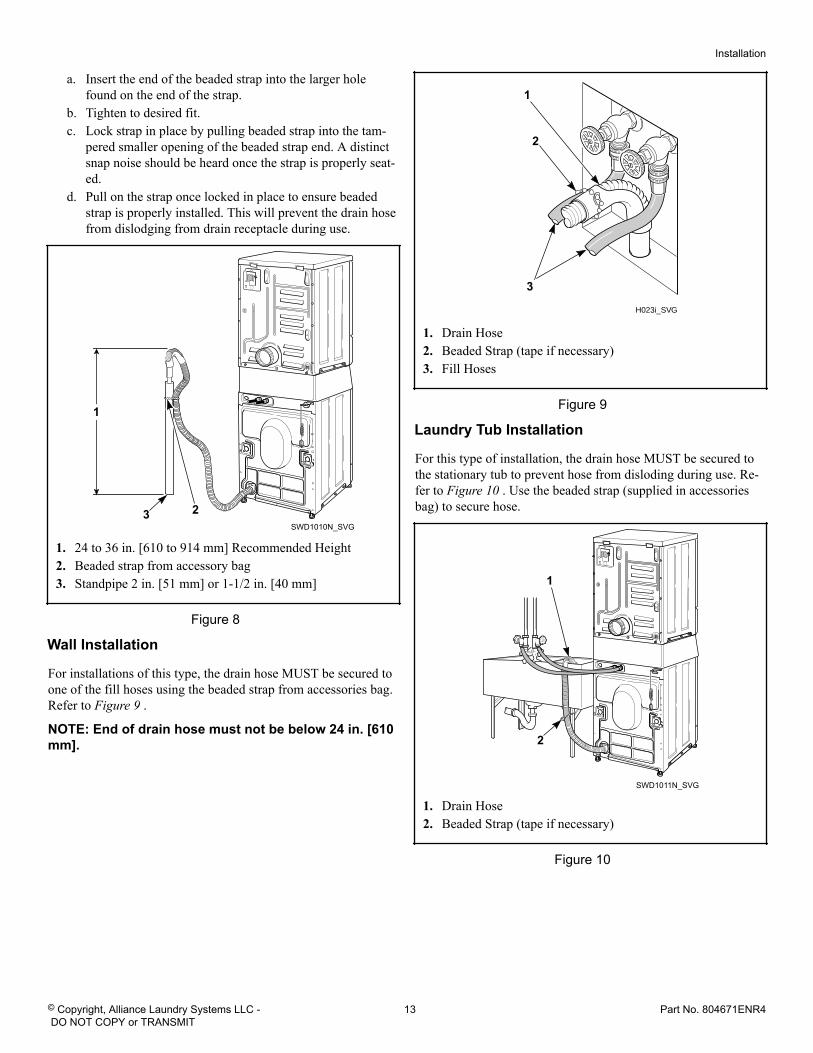
Risers (or air cushions) may have to be installed if the pipesknock or pound when flow of water stops. The risers are more ef-ficient when installed as close as possible to the water supply fau-cets. Refer to Figure 7 .
W005I_SVG
2
1
1. Risers (Air cushions)2. Water Supply Faucets
Figure 7
Connect Drain Hose to DrainReceptacleRemove the drain hose from its shipping position on the rear ofthe washer by unhooking the hose from the retainer clamp and byremoving the shipping tape.
Install the drain hose into the drain receptacle (standpipe, wall orlaundry tub) following the instructions below.
IMPORTANT: Drain receptacle must be capable of han-dling a minimum of 1-1/4 inch [32 mm] outside diame-ter drain hose.
Drain Flow Rate
Drain Height
Flow Rate
gallons per minute [lit-ers per minute]
3 ft. [0.9 m] 8.6 [32.7]
5 ft. [1.5 m] 6.8 [25.9]
6 ft. [1.8 m] 6.0 [22.7]
7 ft. [2.1 m] 5.1 [19.5]
8 ft. [2.4 m] 4.0 [15.2]
Standpipe Installation
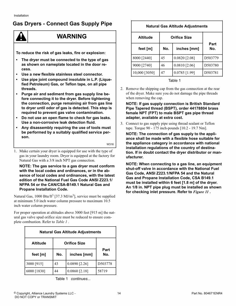
1. Place the drain hose into the standpipe.2. Remove the beaded tie-down strap from accessories bag and
place around standpipe and drain hose. Refer to Figure 8 .
Installation
© Copyright, Alliance Laundry Systems LLC - DO NOT COPY or TRANSMIT
12 Part No. 804671ENR4
a. Insert the end of the beaded strap into the larger holefound on the end of the strap.
b. Tighten to desired fit.c. Lock strap in place by pulling beaded strap into the tam-
pered smaller opening of the beaded strap end. A distinctsnap noise should be heard once the strap is properly seat-ed.
d. Pull on the strap once locked in place to ensure beadedstrap is properly installed. This will prevent the drain hosefrom dislodging from drain receptacle during use.
SWD1010N_SVG3 2
1
1. 24 to 36 in. [610 to 914 mm] Recommended Height2. Beaded strap from accessory bag3. Standpipe 2 in. [51 mm] or 1-1/2 in. [40 mm]
Figure 8
Wall Installation
For installations of this type, the drain hose MUST be secured toone of the fill hoses using the beaded strap from accessories bag.Refer to Figure 9 .
NOTE: End of drain hose must not be below 24 in. [610mm].
H023i_SVG
1
3
2
1. Drain Hose2. Beaded Strap (tape if necessary)3. Fill Hoses
Figure 9
Laundry Tub Installation
For this type of installation, the drain hose MUST be secured tothe stationary tub to prevent hose from disloding during use. Re-fer to Figure 10 . Use the beaded strap (supplied in accessoriesbag) to secure hose.
SWD1011N_SVG
2
1
1. Drain Hose2. Beaded Strap (tape if necessary)
Figure 10
Installation
© Copyright, Alliance Laundry Systems LLC - DO NOT COPY or TRANSMIT
13 Part No. 804671ENR4
Gas Dryers - Connect Gas Supply Pipe
WARNING
To reduce the risk of gas leaks, fire or explosion:
• The dryer must be connected to the type of gasas shown on nameplate located in the door re-cess.
• Use a new flexible stainless steel connector.• Use pipe joint compound insoluble in L.P. (Lique-
fied Petroleum) Gas, or Teflon tape, on all pipethreads.
• Purge air and sediment from gas supply line be-fore connecting it to the dryer. Before tighteningthe connection, purge remaining air from gas lineto dryer until odor of gas is detected. This step isrequired to prevent gas valve contamination.
• Do not use an open flame to check for gas leaks.Use a non-corrosive leak detection fluid.
• Any disassembly requiring the use of tools mustbe performed by a suitably qualified service per-son.
W316
1. Make certain your dryer is equipped for use with the type ofgas in your laundry room. Dryer is equipped at the factory forNatural Gas with a 3/8 inch NPT gas connection.NOTE: The gas service to a gas dryer must conformwith the local codes and ordinances, or in the ab-sence of local codes and ordinances, with the latestedition of the National Fuel Gas Code ANSI Z223.1/NFPA 54 or the CAN/CSA-B149.1 Natural Gas andPropane Installation Code.
Natural Gas, 1000 Btu/ft3 [37.3 MJ/m3], service must be suppliedat minimum 5.0 inch water column pressure to maximum 10.5inch water column pressure.
For proper operation at altitudes above 3000 feet [915 m] the nat-ural gas valve spud orifice size must be reduced to ensure com-plete combustion. Refer to Table 1 .
Natural Gas Altitude Adjustments
Altitude Orifice SizePartNo.feet [m] No. inches [mm]
3000 [915] 43 0.0890 [2.26] D503778
6000 [1830] 44 0.0860 [2.18] 58719
Table 1 continues...
Natural Gas Altitude Adjustments
Altitude Orifice SizePartNo.feet [m] No. inches [mm]
8000 [2440] 45 0.0820 [2.08] D503779
9000 [2740] 46 0.0810 [2.06] D503780
10,000 [3050] 47 0.0785 [1.99] D503781
Table 1
2. Remove the shipping cap from the gas connection at the rearof the dryer. Make sure you do not damage the pipe threadswhen removing the cap.NOTE: If gas supply connection is British StandardPipe Tapered thread (BSPT), order 44178804 brassfemale NPT (FPT) to male BSPT gas pipe threadadapter, available at extra cost.
3. Connect to gas supply pipe using thread sealant or Teflontape. Torque 90 - 175 inch-pounds [10.2 - 19.7 Nm].NOTE: The connection of gas supply to the appli-ance shall be made with a flexible hose suitable forthe appliance category in accordance with nationalinstallation regulations of the country of destina-tion. If in doubt contact the dryer distributor or man-ufacturer.
NOTE: When connecting to a gas line, an equipmentshut-off valve in accordance with the National FuelGas Code, ANSI Z223.1/NFPA 54 and the NaturalGas and Propane Installation Code, CSA B149.1must be installed within 6 feet [1.8 m] of the dryer.An 1/8 in. NPT pipe plug must be installed as shownfor checking inlet pressure. Refer to Figure 11 .
Installation
© Copyright, Alliance Laundry Systems LLC - DO NOT COPY or TRANSMIT
14 Part No. 804671ENR4
D233I_SVG
2
34
1
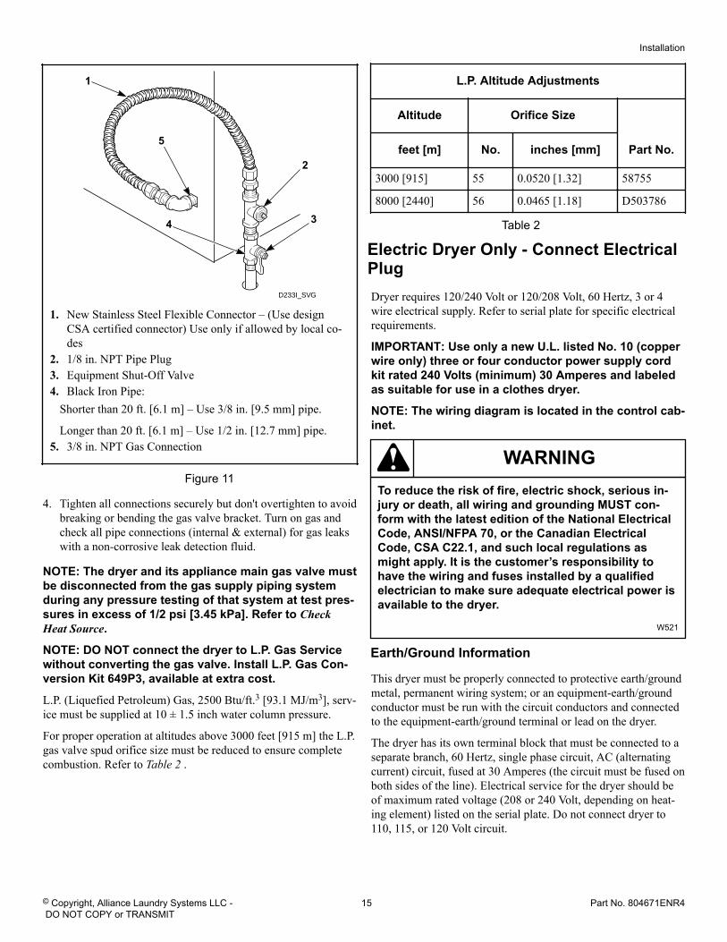
5
1. New Stainless Steel Flexible Connector – (Use designCSA certified connector) Use only if allowed by local co-des
2. 1/8 in. NPT Pipe Plug3. Equipment Shut-Off Valve4. Black Iron Pipe:
Shorter than 20 ft. [6.1 m] – Use 3/8 in. [9.5 mm] pipe.
Longer than 20 ft. [6.1 m] – Use 1/2 in. [12.7 mm] pipe.5. 3/8 in. NPT Gas Connection
Figure 11
4. Tighten all connections securely but don't overtighten to avoidbreaking or bending the gas valve bracket. Turn on gas andcheck all pipe connections (internal & external) for gas leakswith a non-corrosive leak detection fluid.
NOTE: The dryer and its appliance main gas valve mustbe disconnected from the gas supply piping systemduring any pressure testing of that system at test pres-sures in excess of 1/2 psi [3.45 kPa]. Refer to CheckHeat Source.
NOTE: DO NOT connect the dryer to L.P. Gas Servicewithout converting the gas valve. Install L.P. Gas Con-version Kit 649P3, available at extra cost.
L.P. (Liquefied Petroleum) Gas, 2500 Btu/ft.3 [93.1 MJ/m3], serv-ice must be supplied at 10 ± 1.5 inch water column pressure.
For proper operation at altitudes above 3000 feet [915 m] the L.P.gas valve spud orifice size must be reduced to ensure completecombustion. Refer to Table 2 .
L.P. Altitude Adjustments
Altitude Orifice Size
Part No.feet [m] No. inches [mm]
3000 [915] 55 0.0520 [1.32] 58755
8000 [2440] 56 0.0465 [1.18] D503786
Table 2
Electric Dryer Only - Connect ElectricalPlugDryer requires 120/240 Volt or 120/208 Volt, 60 Hertz, 3 or 4wire electrical supply. Refer to serial plate for specific electricalrequirements.
IMPORTANT: Use only a new U.L. listed No. 10 (copperwire only) three or four conductor power supply cordkit rated 240 Volts (minimum) 30 Amperes and labeledas suitable for use in a clothes dryer.
NOTE: The wiring diagram is located in the control cab-inet.
WARNINGTo reduce the risk of fire, electric shock, serious in-jury or death, all wiring and grounding MUST con-form with the latest edition of the National ElectricalCode, ANSI/NFPA 70, or the Canadian ElectricalCode, CSA C22.1, and such local regulations asmight apply. It is the customer’s responsibility tohave the wiring and fuses installed by a qualifiedelectrician to make sure adequate electrical power isavailable to the dryer.
W521
Earth/Ground Information
This dryer must be properly connected to protective earth/groundmetal, permanent wiring system; or an equipment-earth/groundconductor must be run with the circuit conductors and connectedto the equipment-earth/ground terminal or lead on the dryer.
The dryer has its own terminal block that must be connected to aseparate branch, 60 Hertz, single phase circuit, AC (alternatingcurrent) circuit, fused at 30 Amperes (the circuit must be fused onboth sides of the line). Electrical service for the dryer should beof maximum rated voltage (208 or 240 Volt, depending on heat-ing element) listed on the serial plate. Do not connect dryer to110, 115, or 120 Volt circuit.
Installation
© Copyright, Alliance Laundry Systems LLC - DO NOT COPY or TRANSMIT
15 Part No. 804671ENR4
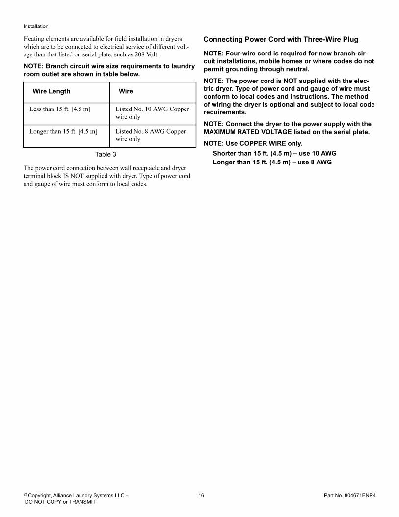
Heating elements are available for field installation in dryerswhich are to be connected to electrical service of different volt-age than that listed on serial plate, such as 208 Volt.
NOTE: Branch circuit wire size requirements to laundryroom outlet are shown in table below.
Wire Length Wire
Less than 15 ft. [4.5 m] Listed No. 10 AWG Copperwire only
Longer than 15 ft. [4.5 m] Listed No. 8 AWG Copperwire only
Table 3
The power cord connection between wall receptacle and dryerterminal block IS NOT supplied with dryer. Type of power cordand gauge of wire must conform to local codes.
Connecting Power Cord with Three-Wire Plug
NOTE: Four-wire cord is required for new branch-cir-cuit installations, mobile homes or where codes do notpermit grounding through neutral.
NOTE: The power cord is NOT supplied with the elec-tric dryer. Type of power cord and gauge of wire mustconform to local codes and instructions. The methodof wiring the dryer is optional and subject to local coderequirements.
NOTE: Connect the dryer to the power supply with theMAXIMUM RATED VOLTAGE listed on the serial plate.
NOTE: Use COPPER WIRE only.Shorter than 15 ft. (4.5 m) – use 10 AWGLonger than 15 ft. (4.5 m) – use 8 AWG
Installation
© Copyright, Alliance Laundry Systems LLC - DO NOT COPY or TRANSMIT
16 Part No. 804671ENR4
D816I_SVG
L1 L2 L1 L21516
5
22
3
4
8
9
1213
10
11
7
6
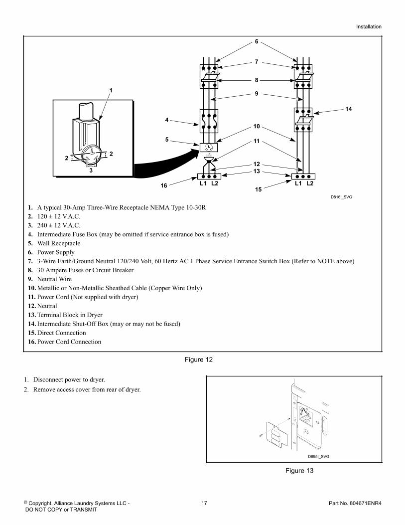
1
14
1. A typical 30-Amp Three-Wire Receptacle NEMA Type 10-30R2. 120 ± 12 V.A.C.3. 240 ± 12 V.A.C.4. Intermediate Fuse Box (may be omitted if service entrance box is fused)5. Wall Receptacle6. Power Supply7. 3-Wire Earth/Ground Neutral 120/240 Volt, 60 Hertz AC 1 Phase Service Entrance Switch Box (Refer to NOTE above)8. 30 Ampere Fuses or Circuit Breaker9. Neutral Wire10. Metallic or Non-Metallic Sheathed Cable (Copper Wire Only)11. Power Cord (Not supplied with dryer)12. Neutral13. Terminal Block in Dryer14. Intermediate Shut-Off Box (may or may not be fused)15. Direct Connection16. Power Cord Connection
Figure 12
1. Disconnect power to dryer.2. Remove access cover from rear of dryer.
D695I_SVG
Figure 13
Installation
© Copyright, Alliance Laundry Systems LLC - DO NOT COPY or TRANSMIT
17 Part No. 804671ENR4
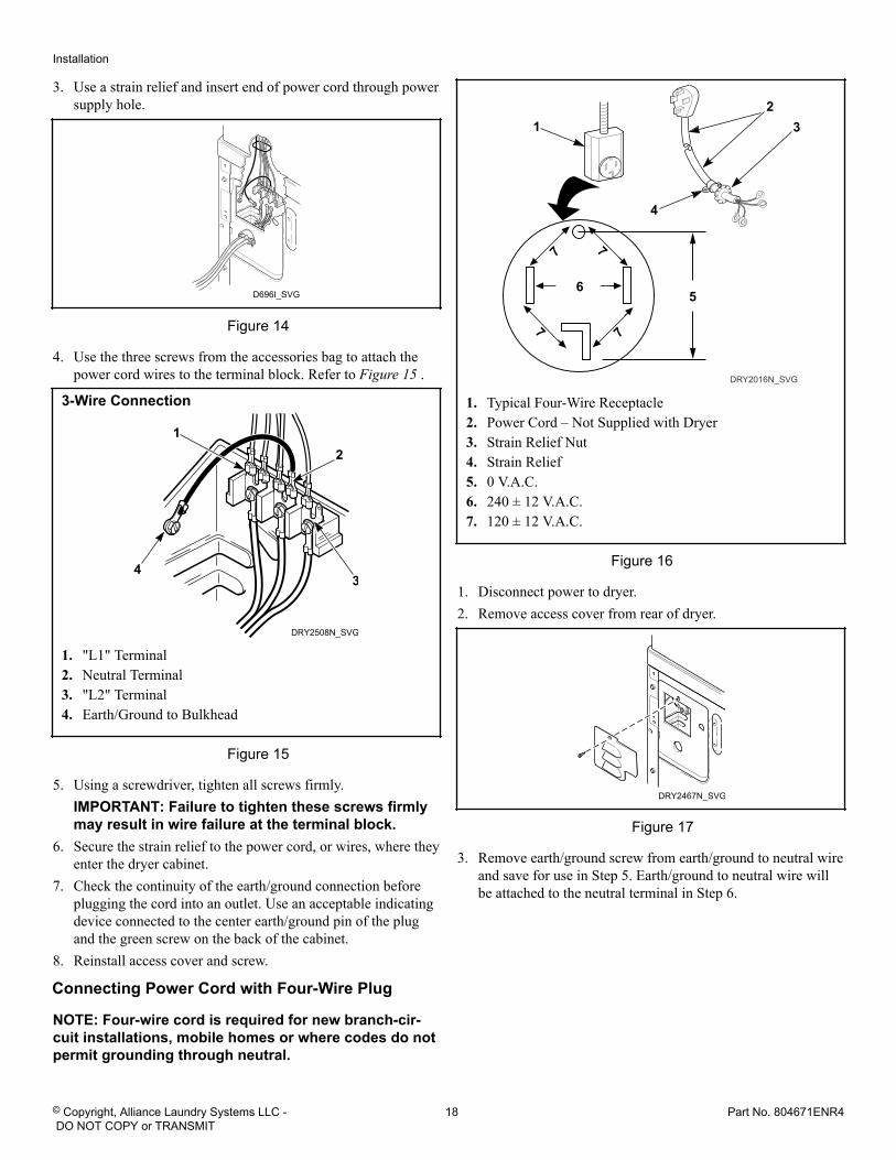
3. Use a strain relief and insert end of power cord through powersupply hole.
D696I_SVG
Figure 14
4. Use the three screws from the accessories bag to attach thepower cord wires to the terminal block. Refer to Figure 15 .
3-Wire Connection
DRY2508N_SVG
43
21
1. "L1" Terminal2. Neutral Terminal3. "L2" Terminal4. Earth/Ground to Bulkhead
Figure 15
5. Using a screwdriver, tighten all screws firmly.IMPORTANT: Failure to tighten these screws firmlymay result in wire failure at the terminal block.
6. Secure the strain relief to the power cord, or wires, where theyenter the dryer cabinet.
7. Check the continuity of the earth/ground connection beforeplugging the cord into an outlet. Use an acceptable indicatingdevice connected to the center earth/ground pin of the plugand the green screw on the back of the cabinet.
8. Reinstall access cover and screw.
Connecting Power Cord with Four-Wire Plug
NOTE: Four-wire cord is required for new branch-cir-cuit installations, mobile homes or where codes do notpermit grounding through neutral.
DRY2016N_SVG
7
7
7
7
6
32
1
4
5
1. Typical Four-Wire Receptacle2. Power Cord – Not Supplied with Dryer3. Strain Relief Nut4. Strain Relief5. 0 V.A.C.6. 240 ± 12 V.A.C.7. 120 ± 12 V.A.C.
Figure 16
1. Disconnect power to dryer.2. Remove access cover from rear of dryer.
DRY2467N_SVG
Figure 17
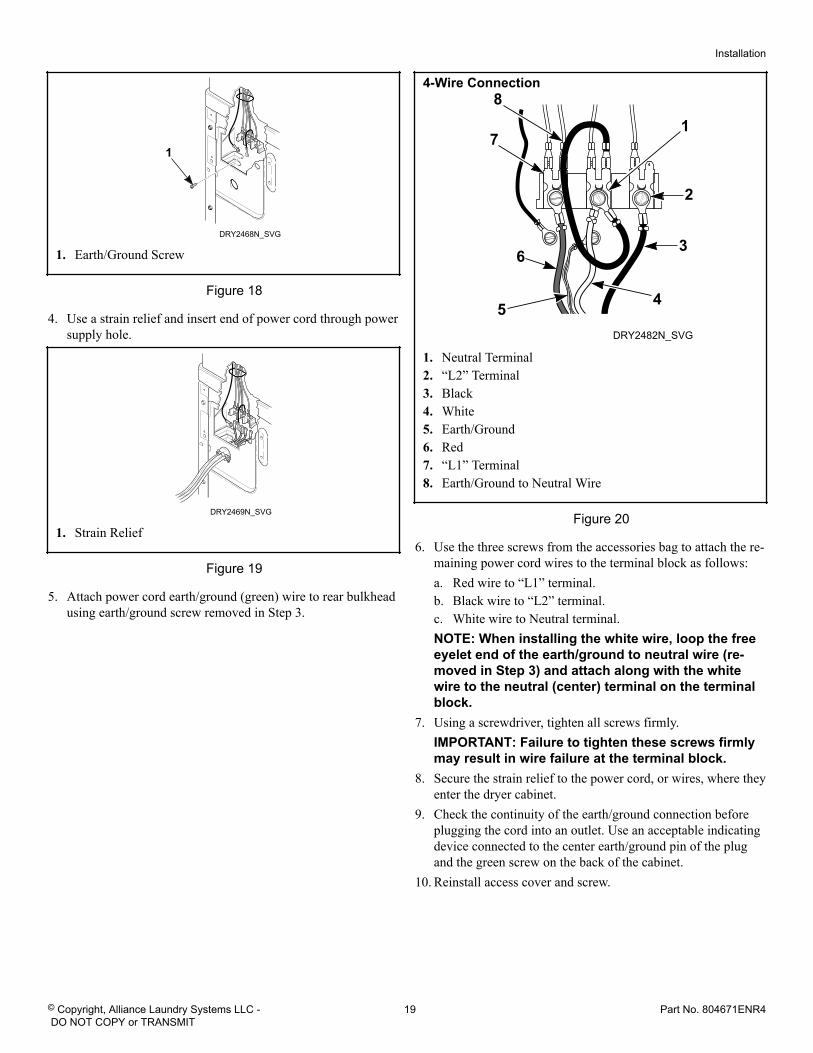
3. Remove earth/ground screw from earth/ground to neutral wireand save for use in Step 5. Earth/ground to neutral wire willbe attached to the neutral terminal in Step 6.
Installation
© Copyright, Alliance Laundry Systems LLC - DO NOT COPY or TRANSMIT
18 Part No. 804671ENR4
DRY2468N_SVG
1
1. Earth/Ground Screw
Figure 18
4. Use a strain relief and insert end of power cord through powersupply hole.
DRY2469N_SVG
1. Strain Relief
Figure 19
5. Attach power cord earth/ground (green) wire to rear bulkheadusing earth/ground screw removed in Step 3.
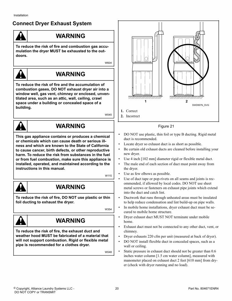
4-Wire Connection
DRY2482N_SVG
1
2
3
45
6
7
8
1. Neutral Terminal2. “L2” Terminal3. Black4. White5. Earth/Ground6. Red7. “L1” Terminal8. Earth/Ground to Neutral Wire
Figure 20
6. Use the three screws from the accessories bag to attach the re-maining power cord wires to the terminal block as follows:a. Red wire to “L1” terminal.b. Black wire to “L2” terminal.c. White wire to Neutral terminal.NOTE: When installing the white wire, loop the freeeyelet end of the earth/ground to neutral wire (re-moved in Step 3) and attach along with the whitewire to the neutral (center) terminal on the terminalblock.
7. Using a screwdriver, tighten all screws firmly.IMPORTANT: Failure to tighten these screws firmlymay result in wire failure at the terminal block.
8. Secure the strain relief to the power cord, or wires, where theyenter the dryer cabinet.
9. Check the continuity of the earth/ground connection beforeplugging the cord into an outlet. Use an acceptable indicatingdevice connected to the center earth/ground pin of the plugand the green screw on the back of the cabinet.
10. Reinstall access cover and screw.
Installation
© Copyright, Alliance Laundry Systems LLC - DO NOT COPY or TRANSMIT
19 Part No. 804671ENR4
Connect Dryer Exhaust System
WARNINGTo reduce the risk of fire and combustion gas accu-mulation the dryer MUST be exhausted to the out-doors.
W604
WARNINGTo reduce the risk of fire and the accumulation ofcombustion gases, DO NOT exhaust dryer air into awindow well, gas vent, chimney or enclosed, unven-tilated area, such as an attic, wall, ceiling, crawlspace under a building or concealed space of abuilding.
W045
WARNINGThis gas appliance contains or produces a chemicalor chemicals which can cause death or serious ill-ness and which are known to the State of Californiato cause cancer, birth defects, or other reproductiveharm. To reduce the risk from substances in the fuelor from fuel combustion, make sure this appliance isinstalled, operated, and maintained according to theinstructions in this manual.
W115
WARNINGTo reduce the risk of fire, DO NOT use plastic or thinfoil ducting to exhaust the dryer.
W354
WARNINGTo reduce the risk of fire, the exhaust duct andweather hood MUST be fabricated of a material thatwill not support combustion. Rigid or flexible metalpipe is recommended for a clothes dryer.
W048
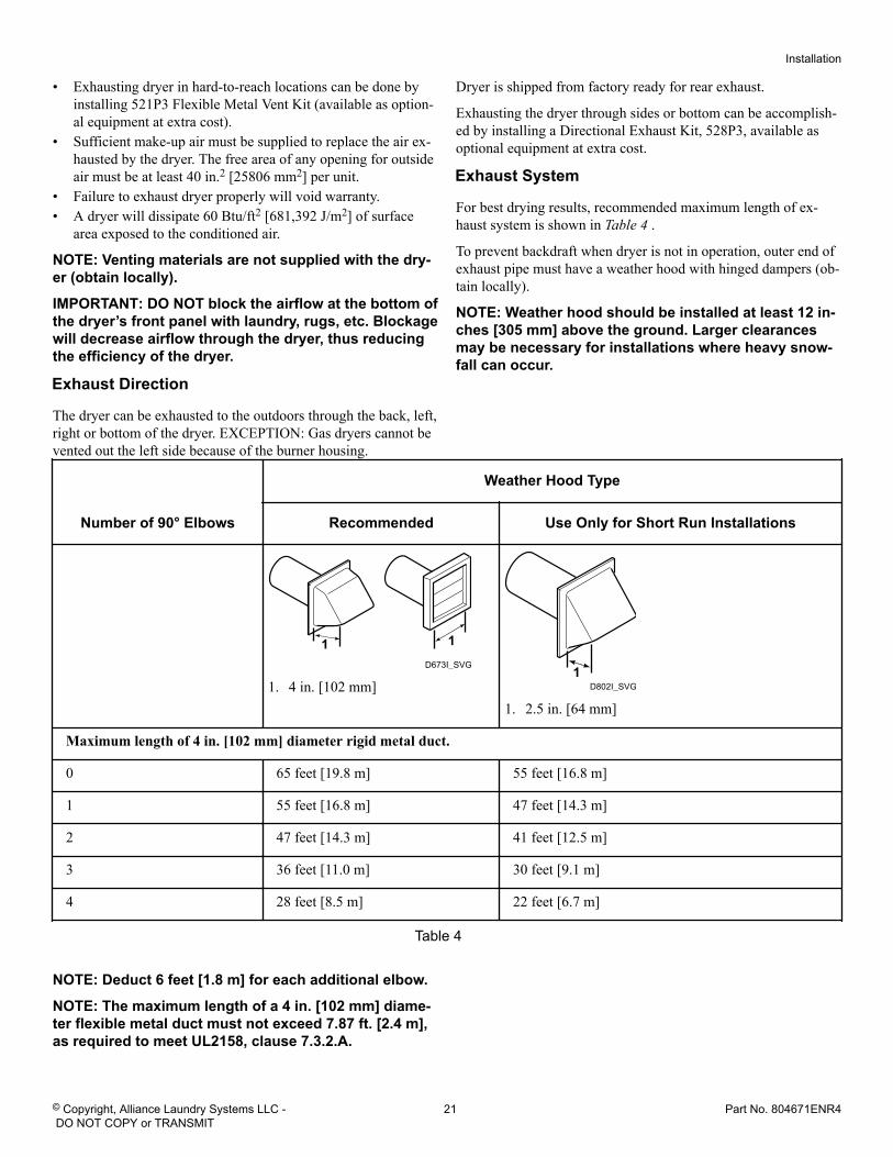
SWD997N_SVG21
1. Correct2. Incorrect
Figure 21
• DO NOT use plastic, thin foil or type B ducting. Rigid metalduct is recommended.
• Locate dryer so exhaust duct is as short as possible.• Be certain old exhaust ducts are cleaned before installing your
new dryer.• Use 4 inch [102 mm] diameter rigid or flexible metal duct.• The male end of each section of duct must point away from
the dryer.• Use as few elbows as possible.• Use of duct tape or pop-rivets on all seams and joints is rec-
ommended, if allowed by local codes. DO NOT use sheetmetal screws or fasteners on exhaust pipe joints which extendinto the duct and catch lint.
• Ductwork that runs through unheated areas must be insulatedto help reduce condensation and lint build-up on pipe walls.
• In mobile home installations, dryer exhaust duct must be se-cured to mobile home structure.
• Dryer exhaust duct MUST NOT terminate under mobilehome.
• Exhaust duct must not be connected to any other duct, vent, orchimney.
• Dryer exhausts 220 cfm per unit (measured at back of dryer).• DO NOT install flexible duct in concealed spaces, such as a
wall or ceiling.• Static pressure in exhaust duct should not be greater than 0.6
inches water column [1.5 cm water column], measured withmanometer placed on exhaust duct 2 feet [610 mm] from dry-er (check with dryer running and no load).
Installation
© Copyright, Alliance Laundry Systems LLC - DO NOT COPY or TRANSMIT
20 Part No. 804671ENR4
• Exhausting dryer in hard-to-reach locations can be done byinstalling 521P3 Flexible Metal Vent Kit (available as option-al equipment at extra cost).
• Sufficient make-up air must be supplied to replace the air ex-hausted by the dryer. The free area of any opening for outsideair must be at least 40 in.2 [25806 mm2] per unit.
• Failure to exhaust dryer properly will void warranty.• A dryer will dissipate 60 Btu/ft2 [681,392 J/m2] of surface
area exposed to the conditioned air.
NOTE: Venting materials are not supplied with the dry-er (obtain locally).
IMPORTANT: DO NOT block the airflow at the bottom ofthe dryer’s front panel with laundry, rugs, etc. Blockagewill decrease airflow through the dryer, thus reducingthe efficiency of the dryer.
Exhaust Direction
The dryer can be exhausted to the outdoors through the back, left,right or bottom of the dryer. EXCEPTION: Gas dryers cannot bevented out the left side because of the burner housing.
Dryer is shipped from factory ready for rear exhaust.
Exhausting the dryer through sides or bottom can be accomplish-ed by installing a Directional Exhaust Kit, 528P3, available asoptional equipment at extra cost.
Exhaust System
For best drying results, recommended maximum length of ex-haust system is shown in Table 4 .
To prevent backdraft when dryer is not in operation, outer end ofexhaust pipe must have a weather hood with hinged dampers (ob-tain locally).
NOTE: Weather hood should be installed at least 12 in-ches [305 mm] above the ground. Larger clearancesmay be necessary for installations where heavy snow-fall can occur.
Number of 90° Elbows
Weather Hood Type
Recommended Use Only for Short Run Installations
D673I_SVG
11
1. 4 in. [102 mm] D802I_SVG1
1. 2.5 in. [64 mm]
Maximum length of 4 in. [102 mm] diameter rigid metal duct.
0 65 feet [19.8 m] 55 feet [16.8 m]
1 55 feet [16.8 m] 47 feet [14.3 m]
2 47 feet [14.3 m] 41 feet [12.5 m]
3 36 feet [11.0 m] 30 feet [9.1 m]
4 28 feet [8.5 m] 22 feet [6.7 m]
Table 4
NOTE: Deduct 6 feet [1.8 m] for each additional elbow.
NOTE: The maximum length of a 4 in. [102 mm] diame-ter flexible metal duct must not exceed 7.87 ft. [2.4 m],as required to meet UL2158, clause 7.3.2.A.
Installation
© Copyright, Alliance Laundry Systems LLC - DO NOT COPY or TRANSMIT
21 Part No. 804671ENR4
Position and Level the Unit
WARNINGUnits elevated above floor level must be anchored tothat elevated surface, base or platform. The materialused to elevate the unit should also be anchored tothe floor to ensure that the unit will not walk or thatthe unit can not be physically pulled, tipped or slidfrom its installed position. Failure to do so may re-sult in conditions which can produce serious injury,death and/or property damage.
W307
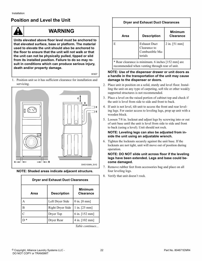
1. Position unit so it has sufficient clearance for installation andservicing.
SWD1006N_SVG
C
E
E
A B
D
NOTE: Shaded areas indicate adjacent structure.
Dryer and Exhaust Duct Clearances
Area DescriptionMinimumClearance
A Left Dryer Side 0 in. [0 mm]
B Right Dryer Side 1 in. [25 mm]
C Dryer Top 6 in. [152 mm]
D * Dryer Rear 4 in. [102 mm]
Table continues...
Dryer and Exhaust Duct Clearances
Area DescriptionMinimumClearance
E Exhaust DuctClearance toCombustible Ma-terials
2 in. [51 mm]
* Rear clearance is minimum. 6 inches [152 mm] arerecommended when venting through rear of unit.
NOTE: Use of the dispenser drawer or unit doors asa handle in the transportation of the unit may causedamage to the dispenser or doors.
2. Place unit in position on a solid, sturdy and level floor. Instal-ling the unit on any type of carpeting, soft tile or other weaklysupported structures is not recommended.
3. Place a level on the raised portion of cabinet top and check ifthe unit is level from side to side and front to back.
4. If unit is not level, tilt unit to access the front and rear level-ing legs. For easier access to leveling legs, prop up unit with awooden block.
5. Loosen 7/8 in. locknut and adjust legs by screwing into or outof unit base until the unit is level from side to side and frontto back (using a level). Unit should not rock.NOTE: Leveling legs can also be adjusted from in-side the unit using an adjustable wrench.
6. Tighten the locknuts securely against the unit base. If thelocknuts are not tight, unit will move out of position duringoperation.NOTE: DO NOT slide unit across floor if the levelinglegs have been extended. Legs and base could be-come damaged.
7. Remove rubber feet from accessories bag and place on allfour leveling legs.
8. Verify that unit doesn’t rock.
Installation
© Copyright, Alliance Laundry Systems LLC - DO NOT COPY or TRANSMIT
22 Part No. 804671ENR4
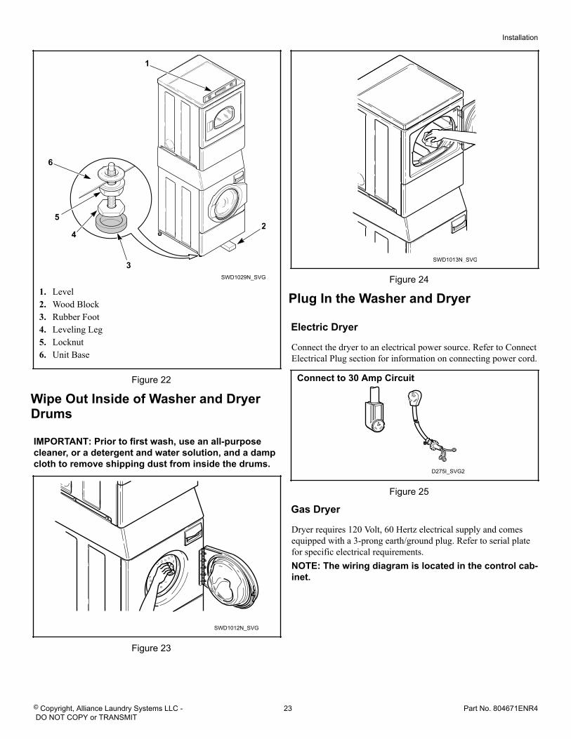
SWD1029N_SVG
4
5
3
2
6
1
1. Level2. Wood Block3. Rubber Foot4. Leveling Leg5. Locknut6. Unit Base
Figure 22
Wipe Out Inside of Washer and DryerDrums
IMPORTANT: Prior to first wash, use an all-purposecleaner, or a detergent and water solution, and a dampcloth to remove shipping dust from inside the drums.
SWD1012N_SVG
Figure 23
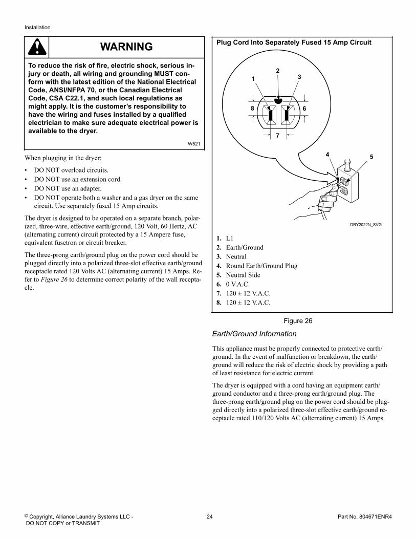
SWD1013N_SVG
Figure 24
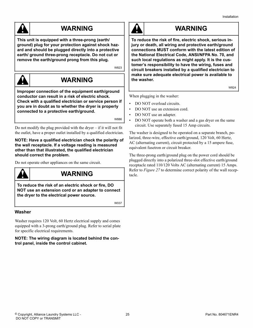
Plug In the Washer and Dryer
Electric Dryer
Connect the dryer to an electrical power source. Refer to ConnectElectrical Plug section for information on connecting power cord.
Connect to 30 Amp Circuit
D275I_SVG2
Figure 25
Gas Dryer
Dryer requires 120 Volt, 60 Hertz electrical supply and comesequipped with a 3-prong earth/ground plug. Refer to serial platefor specific electrical requirements.NOTE: The wiring diagram is located in the control cab-inet.
Installation
© Copyright, Alliance Laundry Systems LLC - DO NOT COPY or TRANSMIT
23 Part No. 804671ENR4
WARNINGTo reduce the risk of fire, electric shock, serious in-jury or death, all wiring and grounding MUST con-form with the latest edition of the National ElectricalCode, ANSI/NFPA 70, or the Canadian ElectricalCode, CSA C22.1, and such local regulations asmight apply. It is the customer’s responsibility tohave the wiring and fuses installed by a qualifiedelectrician to make sure adequate electrical power isavailable to the dryer.
W521
When plugging in the dryer:
• DO NOT overload circuits.• DO NOT use an extension cord.• DO NOT use an adapter.• DO NOT operate both a washer and a gas dryer on the same
circuit. Use separately fused 15 Amp circuits.
The dryer is designed to be operated on a separate branch, polar-ized, three-wire, effective earth/ground, 120 Volt, 60 Hertz, AC(alternating current) circuit protected by a 15 Ampere fuse,equivalent fusetron or circuit breaker.
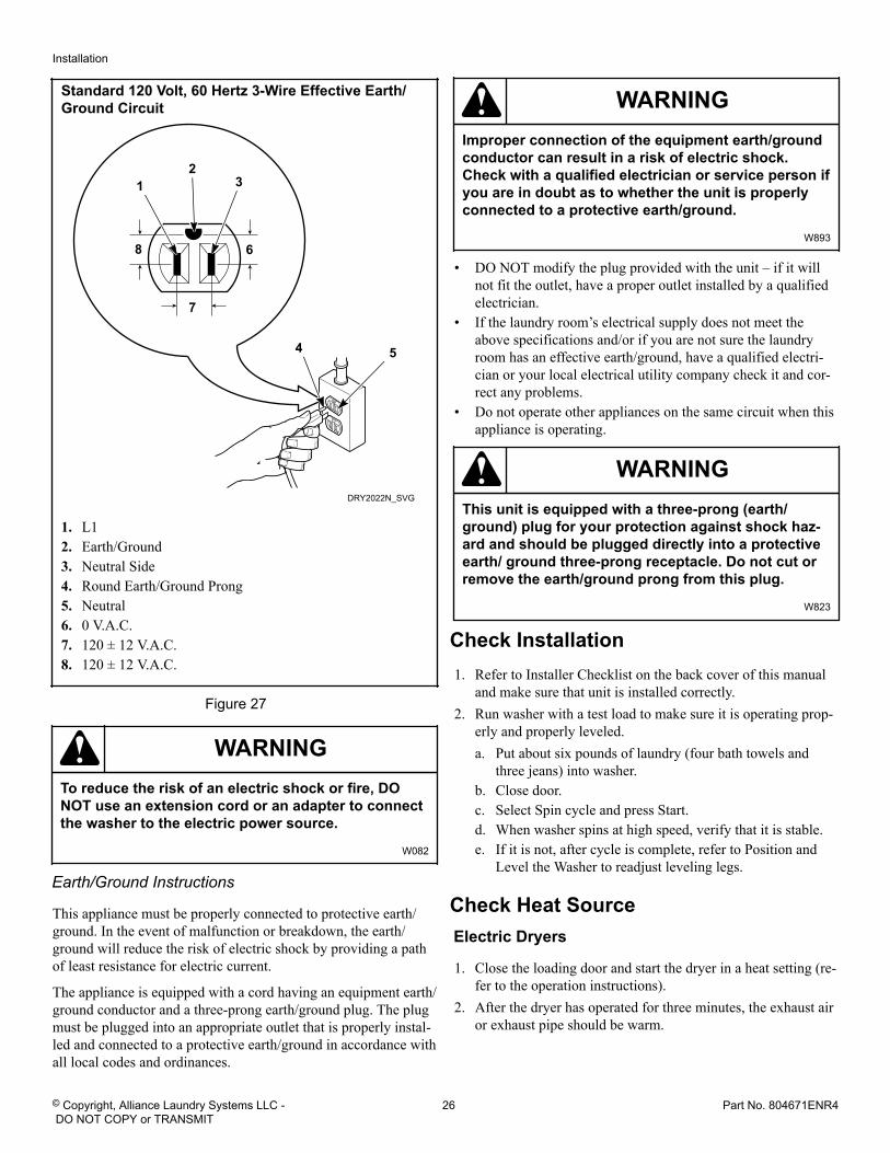
The three-prong earth/ground plug on the power cord should beplugged directly into a polarized three-slot effective earth/groundreceptacle rated 120 Volts AC (alternating current) 15 Amps. Re-fer to Figure 26 to determine correct polarity of the wall recepta-cle.
Plug Cord Into Separately Fused 15 Amp Circuit
DRY2022N_SVG
7
68
54
32
1
1. L12. Earth/Ground3. Neutral4. Round Earth/Ground Plug5. Neutral Side6. 0 V.A.C.7. 120 ± 12 V.A.C.8. 120 ± 12 V.A.C.
Figure 26
Earth/Ground Information
This appliance must be properly connected to protective earth/ground. In the event of malfunction or breakdown, the earth/ground will reduce the risk of electric shock by providing a pathof least resistance for electric current.
The dryer is equipped with a cord having an equipment earth/ground conductor and a three-prong earth/ground plug. Thethree-prong earth/ground plug on the power cord should be plug-ged directly into a polarized three-slot effective earth/ground re-ceptacle rated 110/120 Volts AC (alternating current) 15 Amps.
Installation
© Copyright, Alliance Laundry Systems LLC - DO NOT COPY or TRANSMIT
24 Part No. 804671ENR4
WARNINGThis unit is equipped with a three-prong (earth/ground) plug for your protection against shock haz-ard and should be plugged directly into a protectiveearth/ ground three-prong receptacle. Do not cut orremove the earth/ground prong from this plug.
W823
WARNINGImproper connection of the equipment earth/groundconductor can result in a risk of electric shock.Check with a qualified electrician or service person ifyou are in doubt as to whether the dryer is properlyconnected to a protective earth/ground.
W886
Do not modify the plug provided with the dryer – if it will not fitthe outlet, have a proper outlet installed by a qualified electrician.
NOTE: Have a qualified electrician check the polarity ofthe wall receptacle. If a voltage reading is measuredother than that illustrated, the qualified electricianshould correct the problem.
Do not operate other appliances on the same circuit.
WARNINGTo reduce the risk of an electric shock or fire, DONOT use an extension cord or an adapter to connectthe dryer to the electrical power source.
W037
Washer
Washer requires 120 Volt, 60 Hertz electrical supply and comesequipped with a 3-prong earth/ground plug. Refer to serial platefor specific electrical requirements.
NOTE: The wiring diagram is located behind the con-trol panel, inside the control cabinet.
WARNINGTo reduce the risk of fire, electric shock, serious in-jury or death, all wiring and protective earth/groundconnections MUST conform with the latest edition ofthe National Electrical Code, ANSI/NFPA No. 70, andsuch local regulations as might apply. It is the cus-tomer’s responsibility to have the wiring, fuses andcircuit breakers installed by a qualified electrician tomake sure adequate electrical power is available tothe washer.
W824
When plugging in the washer:
• DO NOT overload circuits.• DO NOT use an extension cord.• DO NOT use an adapter.• DO NOT operate both a washer and a gas dryer on the same
circuit. Use separately fused 15 Amp circuits.
The washer is designed to be operated on a separate branch, po-larized, three-wire, effective earth/ground, 120 Volt, 60 Hertz,AC (alternating current), circuit protected by a 15 ampere fuse,equivalent fusetron or circuit breaker.
The three-prong earth/ground plug on the power cord should beplugged directly into a polarized three-slot effective earth/groundreceptacle rated 110/120 Volts AC (alternating current) 15 Amps.Refer to Figure 27 to determine correct polarity of the wall recep-tacle.
Installation
© Copyright, Alliance Laundry Systems LLC - DO NOT COPY or TRANSMIT
25 Part No. 804671ENR4
Standard 120 Volt, 60 Hertz 3-Wire Effective Earth/Ground Circuit
DRY2022N_SVG
7
68
54
32
1
1. L12. Earth/Ground3. Neutral Side4. Round Earth/Ground Prong5. Neutral6. 0 V.A.C.7. 120 ± 12 V.A.C.8. 120 ± 12 V.A.C.
Figure 27
WARNINGTo reduce the risk of an electric shock or fire, DONOT use an extension cord or an adapter to connectthe washer to the electric power source.
W082
Earth/Ground Instructions
This appliance must be properly connected to protective earth/ground. In the event of malfunction or breakdown, the earth/ground will reduce the risk of electric shock by providing a pathof least resistance for electric current.
The appliance is equipped with a cord having an equipment earth/ground conductor and a three-prong earth/ground plug. The plugmust be plugged into an appropriate outlet that is properly instal-led and connected to a protective earth/ground in accordance withall local codes and ordinances.
WARNINGImproper connection of the equipment earth/groundconductor can result in a risk of electric shock.Check with a qualified electrician or service person ifyou are in doubt as to whether the unit is properlyconnected to a protective earth/ground.
W893
• DO NOT modify the plug provided with the unit – if it willnot fit the outlet, have a proper outlet installed by a qualifiedelectrician.
• If the laundry room’s electrical supply does not meet theabove specifications and/or if you are not sure the laundryroom has an effective earth/ground, have a qualified electri-cian or your local electrical utility company check it and cor-rect any problems.
• Do not operate other appliances on the same circuit when thisappliance is operating.
WARNINGThis unit is equipped with a three-prong (earth/ground) plug for your protection against shock haz-ard and should be plugged directly into a protectiveearth/ ground three-prong receptacle. Do not cut orremove the earth/ground prong from this plug.
W823
Check Installation1. Refer to Installer Checklist on the back cover of this manual
and make sure that unit is installed correctly.2. Run washer with a test load to make sure it is operating prop-
erly and properly leveled.a. Put about six pounds of laundry (four bath towels and
three jeans) into washer.b. Close door.c. Select Spin cycle and press Start.d. When washer spins at high speed, verify that it is stable.e. If it is not, after cycle is complete, refer to Position and
Level the Washer to readjust leveling legs.
Check Heat Source Electric Dryers
1. Close the loading door and start the dryer in a heat setting (re-fer to the operation instructions).
2. After the dryer has operated for three minutes, the exhaust airor exhaust pipe should be warm.
Installation
© Copyright, Alliance Laundry Systems LLC - DO NOT COPY or TRANSMIT
26 Part No. 804671ENR4
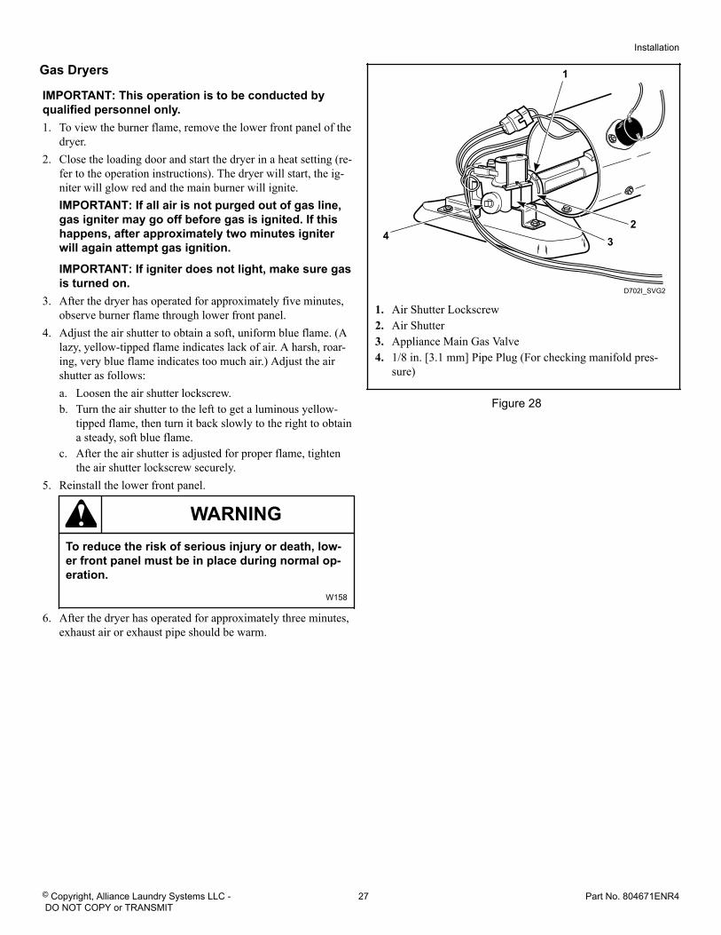
Gas Dryers
IMPORTANT: This operation is to be conducted byqualified personnel only.1. To view the burner flame, remove the lower front panel of the
dryer.2. Close the loading door and start the dryer in a heat setting (re-
fer to the operation instructions). The dryer will start, the ig-niter will glow red and the main burner will ignite.IMPORTANT: If all air is not purged out of gas line,gas igniter may go off before gas is ignited. If thishappens, after approximately two minutes igniterwill again attempt gas ignition.
IMPORTANT: If igniter does not light, make sure gasis turned on.
3. After the dryer has operated for approximately five minutes,observe burner flame through lower front panel.
4. Adjust the air shutter to obtain a soft, uniform blue flame. (Alazy, yellow-tipped flame indicates lack of air. A harsh, roar-ing, very blue flame indicates too much air.) Adjust the airshutter as follows:a. Loosen the air shutter lockscrew.b. Turn the air shutter to the left to get a luminous yellow-
tipped flame, then turn it back slowly to the right to obtaina steady, soft blue flame.
c. After the air shutter is adjusted for proper flame, tightenthe air shutter lockscrew securely.
5. Reinstall the lower front panel.
WARNINGTo reduce the risk of serious injury or death, low-er front panel must be in place during normal op-eration.
W158
6. After the dryer has operated for approximately three minutes,exhaust air or exhaust pipe should be warm.
D702I_SVG2
4
1
23
1. Air Shutter Lockscrew2. Air Shutter3. Appliance Main Gas Valve4. 1/8 in. [3.1 mm] Pipe Plug (For checking manifold pres-
sure)
Figure 28
Installation
© Copyright, Alliance Laundry Systems LLC - DO NOT COPY or TRANSMIT
27 Part No. 804671ENR4
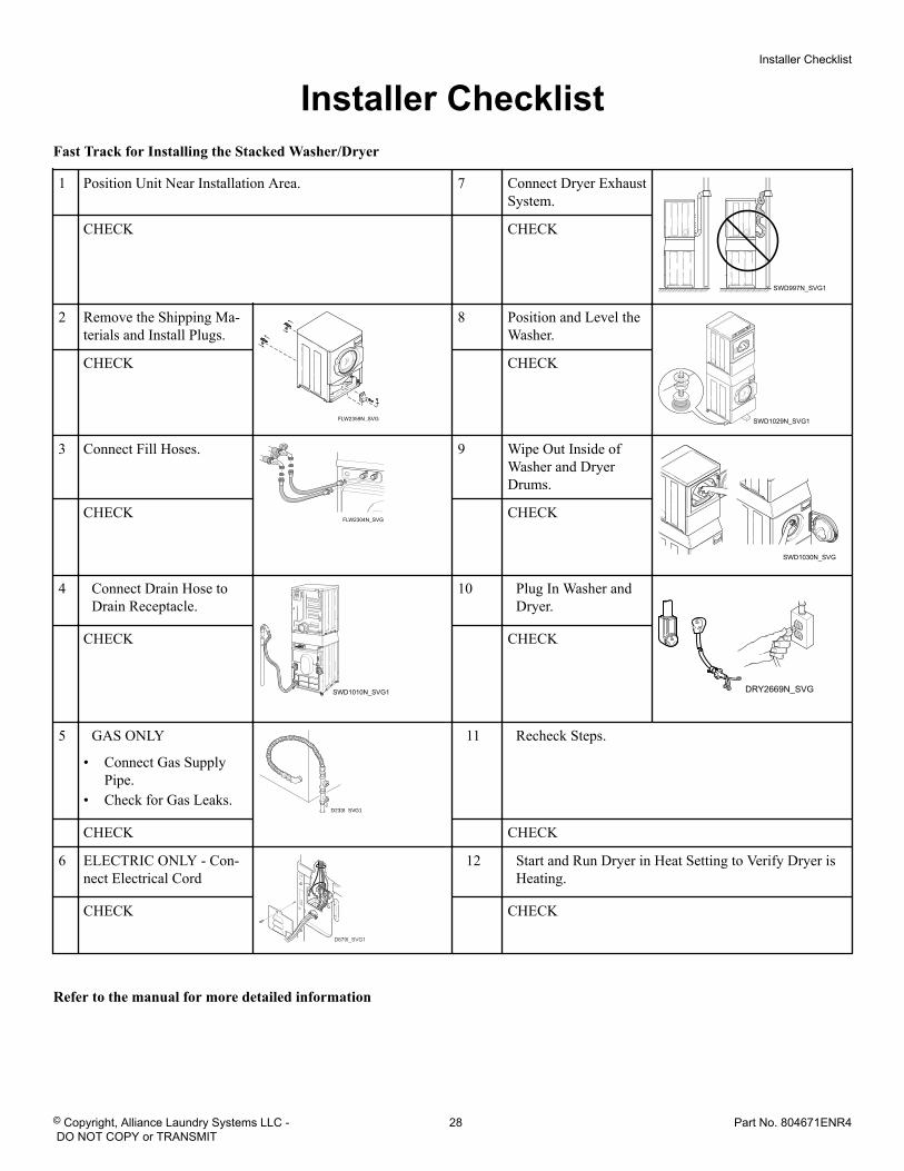
Installer ChecklistFast Track for Installing the Stacked Washer/Dryer
1 Position Unit Near Installation Area. 7 Connect Dryer ExhaustSystem.
SWD997N_SVG1
CHECK CHECK
2 Remove the Shipping Ma-terials and Install Plugs.
FLW2359N_SVG
8 Position and Level theWasher.
SWD1029N_SVG1
CHECK CHECK
3 Connect Fill Hoses.
FLW2304N_SVG
COLD
HOT
9 Wipe Out Inside ofWasher and DryerDrums.
SWD1030N_SVG
CHECK CHECK
4 Connect Drain Hose toDrain Receptacle.
SWD1010N_SVG1
10 Plug In Washer andDryer.
DRY2669N_SVG
CHECK CHECK
5 GAS ONLY
• Connect Gas SupplyPipe.
• Check for Gas Leaks.D233I_SVG1
11 Recheck Steps.
CHECK CHECK
6 ELECTRIC ONLY - Con-nect Electrical Cord
D679I_SVG1
12 Start and Run Dryer in Heat Setting to Verify Dryer isHeating.
CHECK CHECK
Refer to the manual for more detailed information
Installer Checklist
© Copyright, Alliance Laundry Systems LLC - DO NOT COPY or TRANSMIT
28 Part No. 804671ENR4