Embed Size (px)
Citation preview
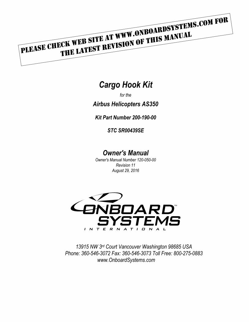
Cargo Hook Kit for the
Airbus Helicopters AS350
Kit Part Number 200-190-00
STC SR00439SE
Owner's Manual
Owner's Manual Number 120-050-00
Revision 11
August 29, 2016
13915 NW 3rd Court Vancouver Washington 98685 USA Phone: 360-546-3072 Fax: 360-546-3073 Toll Free: 800-275-0883
www.OnboardSystems.com

This page intentionally left blank.
ii
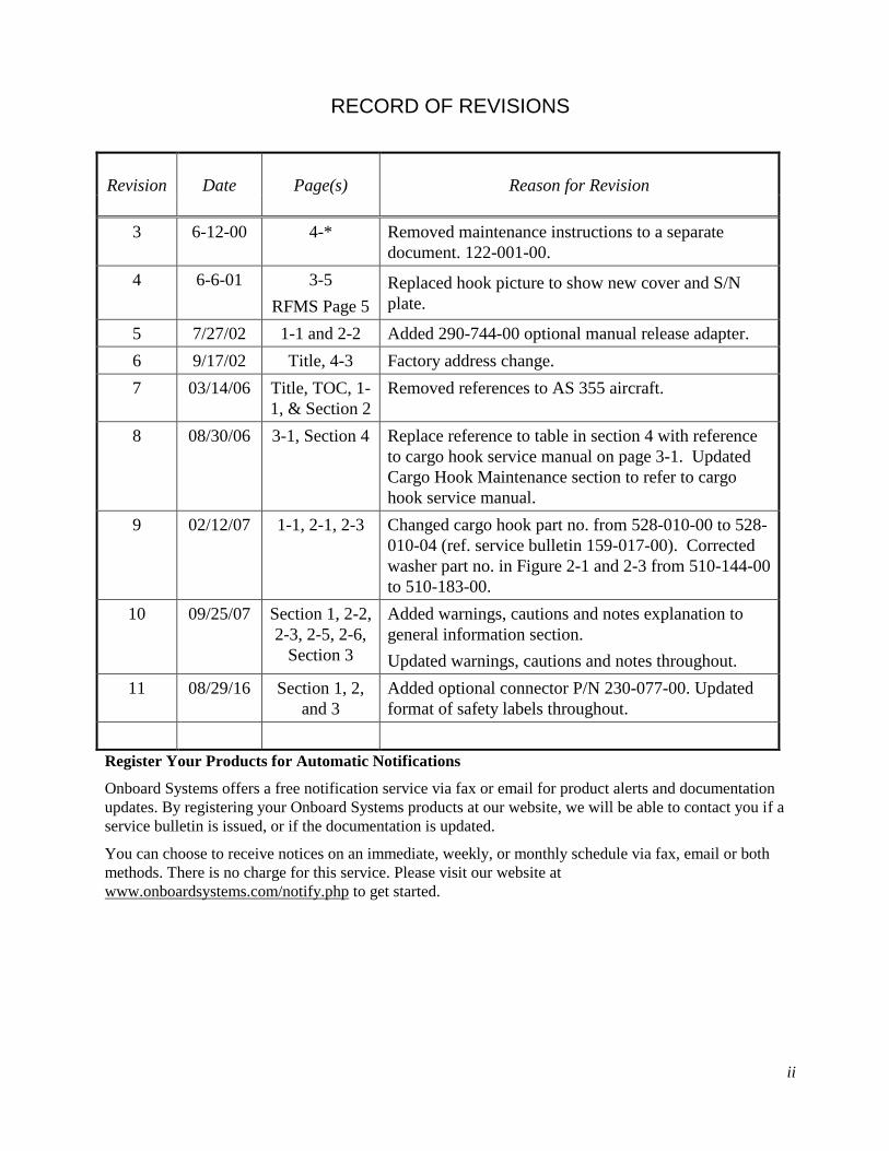
RECORD OF REVISIONS
Revision
Date
Page(s)
Reason for Revision
3 6-12-00 4-* Removed maintenance instructions to a separate
document. 122-001-00.
4 6-6-01 3-5
RFMS Page 5
Replaced hook picture to show new cover and S/N
plate.
5 7/27/02 1-1 and 2-2 Added 290-744-00 optional manual release adapter.
6 9/17/02 Title, 4-3 Factory address change.
7 03/14/06 Title, TOC, 1-
1, & Section 2
Removed references to AS 355 aircraft.
8 08/30/06 3-1, Section 4 Replace reference to table in section 4 with reference
to cargo hook service manual on page 3-1. Updated
Cargo Hook Maintenance section to refer to cargo
hook service manual.
9 02/12/07 1-1, 2-1, 2-3 Changed cargo hook part no. from 528-010-00 to 528-
010-04 (ref. service bulletin 159-017-00). Corrected
washer part no. in Figure 2-1 and 2-3 from 510-144-00
to 510-183-00.
10 09/25/07 Section 1, 2-2,
2-3, 2-5, 2-6,
Section 3
Added warnings, cautions and notes explanation to
general information section.
Updated warnings, cautions and notes throughout.
11 08/29/16 Section 1, 2,
and 3
Added optional connector P/N 230-077-00. Updated
format of safety labels throughout.
Register Your Products for Automatic Notifications
Onboard Systems offers a free notification service via fax or email for product alerts and documentation
updates. By registering your Onboard Systems products at our website, we will be able to contact you if a
service bulletin is issued, or if the documentation is updated.
You can choose to receive notices on an immediate, weekly, or monthly schedule via fax, email or both
methods. There is no charge for this service. Please visit our website at
www.onboardsystems.com/notify.php to get started.

This page intentionally left blank.
iii
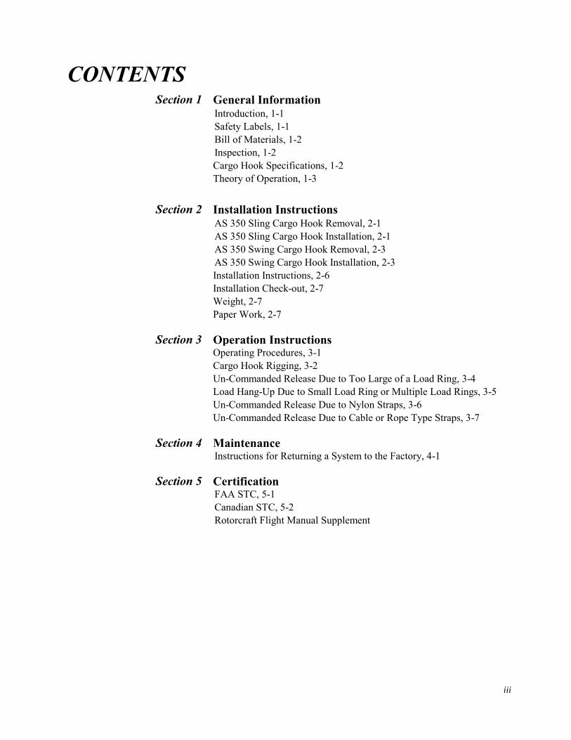
CONTENTS Section 1 General Information
Introduction, 1-1
Safety Labels, 1-1
Bill of Materials, 1-2
Inspection, 1-2
Cargo Hook Specifications, 1-2
Theory of Operation, 1-3
Section 2 Installation Instructions AS 350 Sling Cargo Hook Removal, 2-1
AS 350 Sling Cargo Hook Installation, 2-1
AS 350 Swing Cargo Hook Removal, 2-3
AS 350 Swing Cargo Hook Installation, 2-3
Installation Instructions, 2-6
Installation Check-out, 2-7
Weight, 2-7
Paper Work, 2-7
Section 3 Operation Instructions Operating Procedures, 3-1
Cargo Hook Rigging, 3-2
Un-Commanded Release Due to Too Large of a Load Ring, 3-4
Load Hang-Up Due to Small Load Ring or Multiple Load Rings, 3-5
Un-Commanded Release Due to Nylon Straps, 3-6
Un-Commanded Release Due to Cable or Rope Type Straps, 3-7
Section 4 Maintenance Instructions for Returning a System to the Factory, 4-1
Section 5 Certification FAA STC, 5-1
Canadian STC, 5-2
Rotorcraft Flight Manual Supplement

This page intentionally left blank.
General Information 1-1
Section 1
General Information Introduction
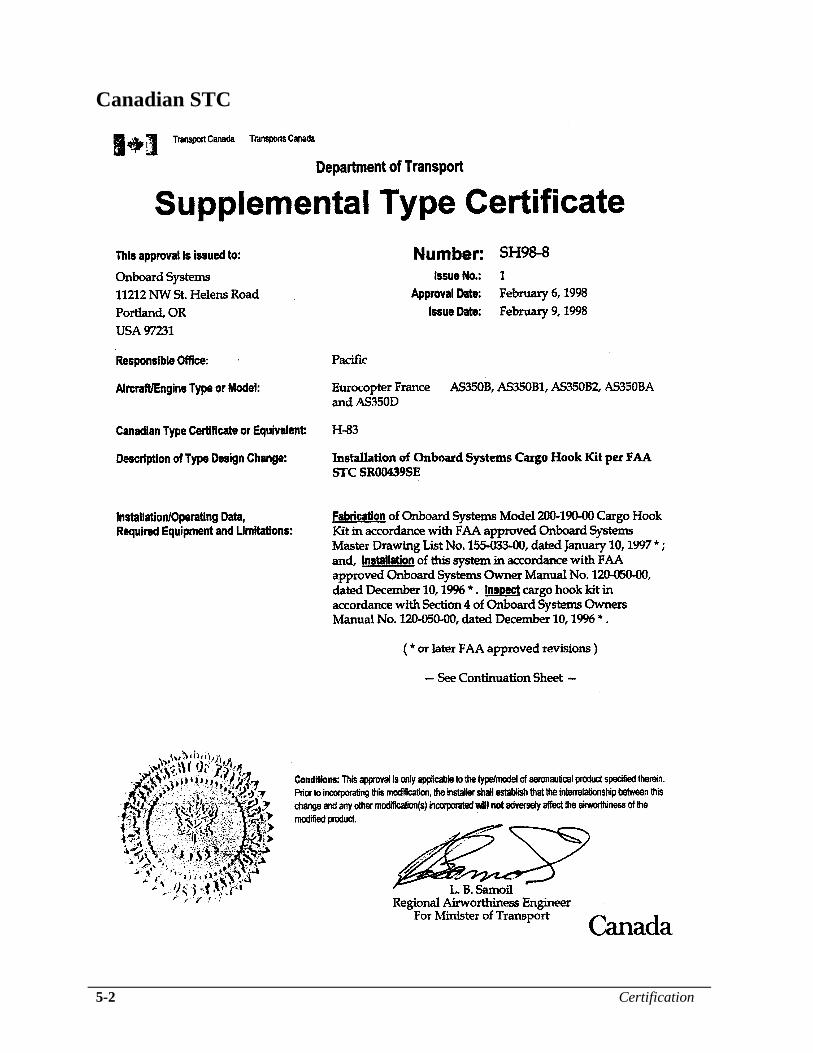
The 200-190-00 Cargo Hook Kit is approved as a replacement for the
following Cargo Hooks on the Airbus Helicopters AS350B, AS350B1,
AS350B2, AS350BA, and AS350D.
Table 1-1 Cargo Hooks
P/N Manufacturer
17149-1 Breeze-Eastern
14027-4 Breeze-Eastern
S1609-3 Siren
S1609-5 Siren
S1609-6 Siren
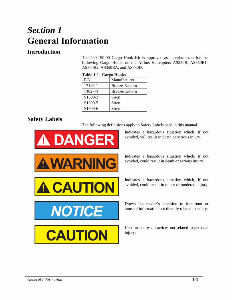
Safety Labels The following definitions apply to Safety Labels used in this manual.
Indicates a hazardous situation which, if not
avoided, will result in death or serious injury.
Indicates a hazardous situation which, if not
avoided, could result in death or serious injury.
Indicates a hazardous situation which, if not
avoided, could result in minor or moderate injury.
Draws the reader’s attention to important or
unusual information not directly related to safety.
Used to address practices not related to personal
injury.
1-2 General Information
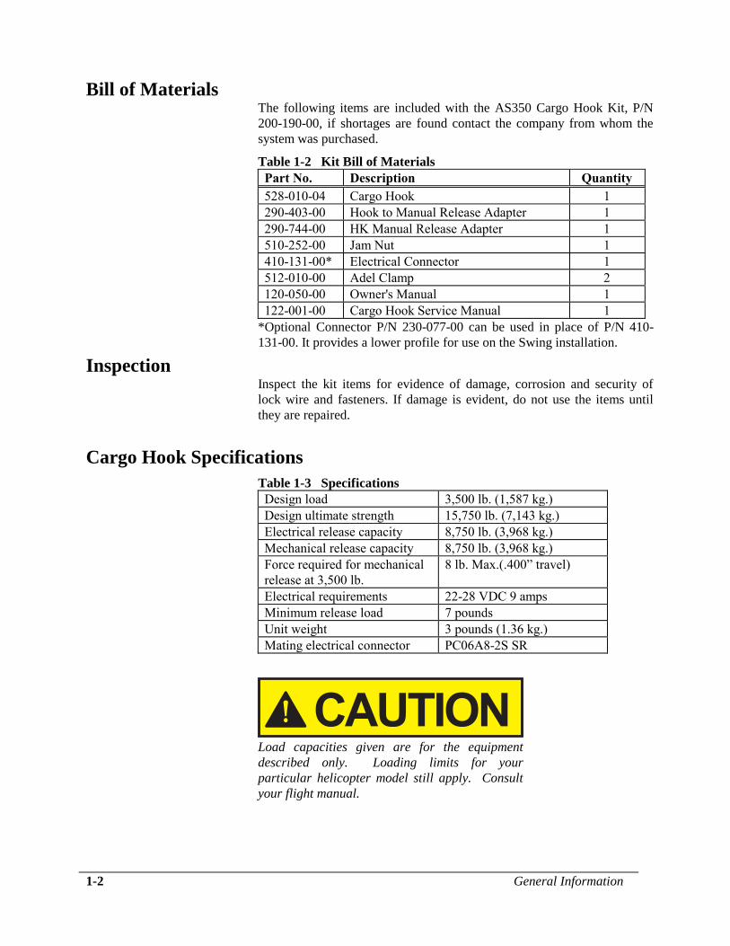
Bill of Materials The following items are included with the AS350 Cargo Hook Kit, P/N
200-190-00, if shortages are found contact the company from whom the
system was purchased.
Table 1-2 Kit Bill of Materials
Part No. Description Quantity
528-010-04 Cargo Hook 1
290-403-00 Hook to Manual Release Adapter 1
290-744-00 HK Manual Release Adapter 1
510-252-00 Jam Nut 1
410-131-00* Electrical Connector 1
512-010-00 Adel Clamp 2
120-050-00 Owner's Manual 1
122-001-00 Cargo Hook Service Manual 1
*Optional Connector P/N 230-077-00 can be used in place of P/N 410-
131-00. It provides a lower profile for use on the Swing installation.
Inspection Inspect the kit items for evidence of damage, corrosion and security of
lock wire and fasteners. If damage is evident, do not use the items until
they are repaired.
Cargo Hook Specifications
Table 1-3 Specifications
Design load 3,500 lb. (1,587 kg.)
Design ultimate strength 15,750 lb. (7,143 kg.)
Electrical release capacity 8,750 lb. (3,968 kg.)
Mechanical release capacity 8,750 lb. (3,968 kg.)
Force required for mechanical
release at 3,500 lb.
8 lb. Max.(.400” travel)
Electrical requirements 22-28 VDC 9 amps
Minimum release load 7 pounds
Unit weight 3 pounds (1.36 kg.)
Mating electrical connector PC06A8-2S SR
Load capacities given are for the equipment
described only. Loading limits for your
particular helicopter model still apply. Consult
your flight manual.
General Information 1-3
Theory of Operation The primary elements of the Cargo Hook are the load beam, the internal
mechanism, and a DC solenoid. The load beam supports the load and is
latched through the internal mechanism. The DC solenoid and an external
manual release cable provide the means for unlatching the load beam.
The load beam is normally returned to its closed position after release of
the load by a spring in the internal mechanism. In the closed position, a
latch engages the load beam and latches it in this position. The load is
attached to the load beam by passing the cargo sling ring into the throat of
the load beam past a spring-loaded keeper, which secures the load.
To release the load, the latch is disengaged from the load beam. With the
latch disengaged, the weight of the load causes the load beam to swing to
its open position, and the cargo sling slides off the load beam. A spring in
the internal mechanism then drives the load beam back to its closed and
latched position.
A load release can be initiated by three different methods. Normal release
is achieved by pilot actuation of a push-button switch in the cockpit.
When the push-button switch is pressed, it energizes the DC solenoid in
the Cargo Hook, and the solenoid opens the latch in the internal
mechanism. In an emergency, release can be achieved by operating a
mechanical release lever. A manual release cable attached to the lever
operates the internal mechanism of the Cargo Hook to unlatch the load
beam. The load can also be released by the actuation of a lever located on
the side of the Cargo Hook.

This page intentionally left blank.
Installation Instructions 2-1
Section 2
Installation Instructions These procedures are provided for the benefit of experienced aircraft
maintenance facilities capable of carrying out the procedures. They must
not be attempted by those lacking the necessary expertise.
AS 350 Sling Cargo Hook Removal Remove the old Cargo Hook from the aircraft by disconnecting the hook
from the load link (gauge shackle) and the manual and electrical release
cables.
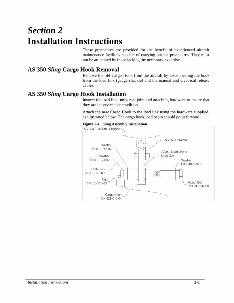
AS 350 Sling Cargo Hook Installation Inspect the load link, universal joint and attaching hardware to insure that
they are in serviceable condition.
Attach the new Cargo Hook to the load link using the hardware supplied,
as illustrated below. The cargo hook load beam should point forward.
Figure 2-1 Sling Assembly Installation
AS 350 Fuel Tank Support
AS350 Load Link or
Load Cell
Attach Bolt
P/N 290-332-00
Washer
P/N 510-183-00
AS 350 Universal
Cargo Hook
P/N 528-010-04
Nut
P/N 510-170-00
Cotter Pin
P/N 510-178-00
Washer
P/N 510-174-00
Washer
PN 510-183-00
2-2 Installation Instructions
AS 350 Sling Cargo Hook Installation, continued Remove the manual release cover from the new Cargo Hook. When
Airbus Helicopters aft release cable AS22-08 is installed, manual release
adapter P/N 290-744-00 will provide the best release cable free play
adjustment. For other cable configurations manual release cable adapter
P/N 290-403-00 will provide best adjustment.
Thread appropriate adapter and jam nut P/N 510-252-00 into the new
Cargo Hook.
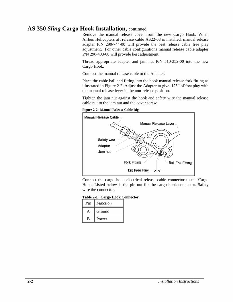
Connect the manual release cable to the Adapter.
Place the cable ball end fitting into the hook manual release fork fitting as
illustrated in Figure 2-2. Adjust the Adapter to give .125” of free play with
the manual release lever in the non-release position.
Tighten the jam nut against the hook and safety wire the manual release
cable nut to the jam nut and the cover screw.
Figure 2-2 Manual Release Cable Rig
Connect the cargo hook electrical release cable connector to the Cargo
Hook. Listed below is the pin out for the cargo hook connector. Safety
wire the connector.
Table 2-1 Cargo Hook Connector
Pin Function
A Ground
B Power
Installation Instructions 2-3
AS 350 Sling Cargo Hook Installation, continued
The Cargo Hook is equipped with a suppression
diode that will be damaged if the Cargo Hook
electrical connections are reversed. Do not
attach the electrical connector until the polarity
of the aircraft connector is determined to be
compatible with the Cargo Hook connector listed
in Table 2-1.
AS 350 Swing Cargo Hook Removal Remove the old Cargo Hook from the aircraft by disconnecting the hook
from the load link (gauge shackle) and the manual and electrical release
cables.
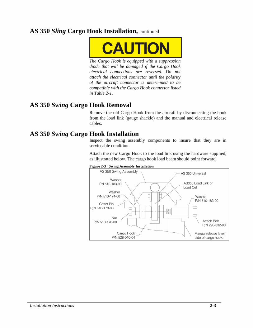
AS 350 Swing Cargo Hook Installation Inspect the swing assembly components to insure that they are in
serviceable condition.
Attach the new Cargo Hook to the load link using the hardware supplied,
as illustrated below. The cargo hook load beam should point forward.
Figure 2-3 Swing Assembly Installation
Cargo Hook
P/N 528-010-04
Nut
P/N 510-170-00
Cotter Pin
P/N 510-178-00
Washer
P/N 510-174-00
Washer
PN 510-183-00
Attach Bolt
P/N 290-332-00
Washer
P/N 510-183-00
Manual release lever
side of cargo hook.
AS 350 Swing Assembly
AS350 Load Link or
Load Cell
AS 350 Universal
2-4 Installation Instructions
AS 350 Swing Cargo Hook Installation, continued Remove the manual release cover from the new Cargo Hook.
Thread the Hook to Manual Release Adapter, P/N 290-403-00 into the
new Cargo Hook.
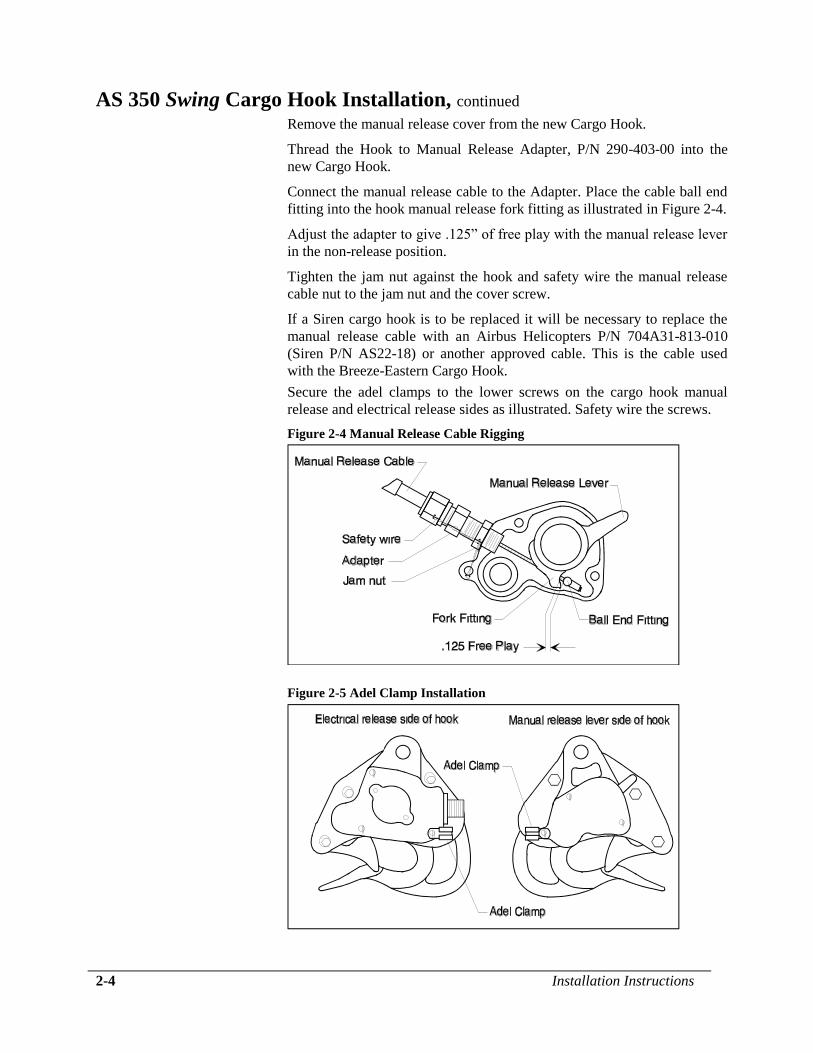
Connect the manual release cable to the Adapter. Place the cable ball end
fitting into the hook manual release fork fitting as illustrated in Figure 2-4.
Adjust the adapter to give .125” of free play with the manual release lever
in the non-release position.
Tighten the jam nut against the hook and safety wire the manual release
cable nut to the jam nut and the cover screw.
If a Siren cargo hook is to be replaced it will be necessary to replace the
manual release cable with an Airbus Helicopters P/N 704A31-813-010
(Siren P/N AS22-18) or another approved cable. This is the cable used
with the Breeze-Eastern Cargo Hook.
Secure the adel clamps to the lower screws on the cargo hook manual
release and electrical release sides as illustrated. Safety wire the screws.
Figure 2-4 Manual Release Cable Rigging
Figure 2-5 Adel Clamp Installation
Installation Instructions 2-5
AS 350 Swing Cargo Hook Installation, continued If the hook removed was manufactured by Siren or if it was a Breeze-
Eastern 14027-4 it will be necessary to replace the connector on the
electrical release cable with the one supplied with the Cargo Hook Kit. If
preferred a short adapter cable can be fabricated to connect the electrical
release cable to the hook. Listed below is the pin out for the cargo hook
connector.
Connect the cargo hook electrical release cable connector to the Cargo
Hook and secure with safety wire.
Table 2-2 Cargo Hook Connector
Pin Function
A Ground
B Power
The Cargo Hook is equipped with a suppression
diode that will be damaged if the Cargo Hook
electrical connections are reversed. Do not attach
the electrical connector until the polarity of the
aircraft connector is determined to be compatible
with the Cargo Hook connector listed in Table 2-
2.
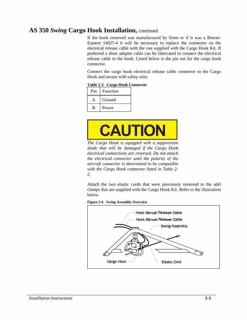
Attach the two elastic cords that were previously removed to the adel
clamps that are supplied with the Cargo Hook Kit. Refer to the illustration
below.
Figure 2-6 Swing Assembly Overview
2-6 Installation Instructions
Installation Instructions
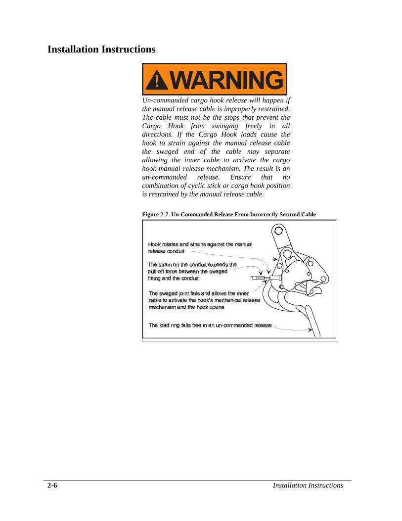
Un-commanded cargo hook release will happen if
the manual release cable is improperly restrained.
The cable must not be the stops that prevent the
Cargo Hook from swinging freely in all
directions. If the Cargo Hook loads cause the
hook to strain against the manual release cable
the swaged end of the cable may separate
allowing the inner cable to activate the cargo
hook manual release mechanism. The result is an
un-commanded release. Ensure that no
combination of cyclic stick or cargo hook position
is restrained by the manual release cable.
Figure 2-7 Un-Commanded Release From Incorrectly Secured Cable
Installation Instructions 2-7
Installation Check-Out After installation of the Cargo Hook, perform the following functional
checks.
1. Swing the installed Cargo Hook to ensure that the manual release cable
assembly and the electrical release cable have enough slack to allow
full swing of the suspension assembly without straining or damaging
the cables. The cables must not be the stops that prevent the Cargo
Hook from swinging freely in all directions. It may be necessary to
install bumper pads on the Swing to prevent the release cables from
being damaged.
2. Apply 10-20 pounds to the cargo hook load beam and pull the handle
operated cargo hook mechanical release, the Cargo Hook must release.
3. Close the cargo hook release circuit breaker and position the battery
switch to the ON position. Apply 10-20 pounds to the cargo hook load
beam and depress the cargo hook electrical release button, the Cargo
Hook must release.
4. See the Airbus Helicopters service instructions for your specific
helicopter model for additional installation instructions.
Weight The weight of the Cargo Hook is listed in Table 2-4.
Table 2-4 Component Weights
Item Weight
lbs (kgs)
Cargo Hook 3.0 (1.36)
Paper Work Remove the Flight Manual Supplement from the back of this manual and
place it into Rotorcraft Flight Manual. In the US, fill in FAA form 337 for
the initial installation. This procedure may vary in different countries.
Make the appropriate aircraft log book entry.

This page intentionally left blank.
Operation Instructions 3-1
Section 3
Operation Instructions Operating Procedures
Prior to a flight involving external load operations perform the following.
1. Ensure that the Cargo Hook has been properly installed and that the
manual and electrical release cables do not limit the movement of the
hook.
2. Be completely familiar with this manual, particularly the Cargo Hook
rigging section.
3. Be completely familiar with all Airbus Helicopters Cargo Hook
operating instructions.
4. Activate the electrical system and press the cargo hook release button
to ensure the cargo hook electrical release is operating correctly. The
mechanism should operate smoothly and the Cargo Hook should re-
latch after release. If the hook does not re-latch do not use the unit
until the difficulty is resolved.
The release solenoid is intended to be energized
only intermittently. Depressing the electrical
release button continuously in excess of 20 sec.
will cause the release solenoid to overheat,
possibly causing permanent damage.
5. Activate the manual release lever to test the cargo hook manual
release mechanism. The mechanism should operate smoothly and the
Cargo Hook must relatch after release. If the hook does not relatch do
not use the unit until the difficulty is resolved.
See the Cargo Hook Component Maintenance Manual 122-001-00 and the
aircraft’s service instructions that cover the original Cargo Hook
installation for additional instructions.
3-2 Operation Instructions
Cargo Hook Rigging Extreme care must be exercised in rigging a load to the Cargo Hook. If the
load ring is too big it may work its way around the end of the load beam
and be supported for a time on the keeper and then fall free. If the load
ring is too small it may jam itself against the load beam during an
attempted release. The following illustrations show recommended
configurations and potential difficulties that must be avoided.
The examples shown are not intended to represent
all problem possibilities. It is the responsibility of
the operator to assure the hook will function
properly with the rigging.
Operation Instructions 3-3
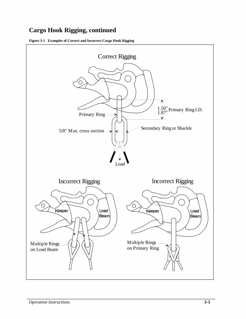
Cargo Hook Rigging, continued Figure 3-1 Examples of Correct and Incorrect Cargo Hook Rigging
Secondary Ring or Shackle5/8" Max. cross section
Load
Primary Ring
Incorrect Rigging Incorrect Rigging
Correct Rigging
Multiple Rings
on Load Beam
Multiple Rings
on Primary Ring
1.50" Primary Ring I.D.1.87"
3-4 Operation Instructions
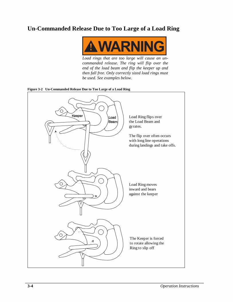
Un-Commanded Release Due to Too Large of a Load Ring
Load rings that are too large will cause an un-
commanded release. The ring will flip over the
end of the load beam and flip the keeper up and
then fall free. Only correctly sized load rings must
be used. See examples below.
Figure 3-2 Un-Commanded Release Due to Too Large of a Load Ring
Load Ring flips over
the Load Beam and
gyrates.
The flip over often occurs
with long line operations
during landings and take offs.
Load Ring moves
inward and bears
against the keeper
The Keeper is forced
to rotate allowing the
Ring to slip off
Operation Instructions 3-5
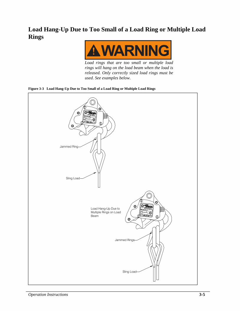
Load Hang-Up Due to Too Small of a Load Ring or Multiple Load
Rings
Load rings that are too small or multiple load
rings will hang on the load beam when the load is
released. Only correctly sized load rings must be
used. See examples below.
Figure 3-3 Load Hang-Up Due to Too Small of a Load Ring or Multiple Load Rings
Jammed Ring
Sling Load
Sling Load
Jammed Rings
Load Hang-Up Due to
Multiple Rings on Load
Beam
3-6 Operation Instructions
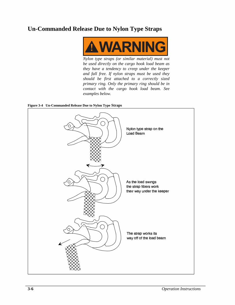
Un-Commanded Release Due to Nylon Type Straps
Nylon type straps (or similar material) must not
be used directly on the cargo hook load beam as
they have a tendency to creep under the keeper
and fall free. If nylon straps must be used they
should be first attached to a correctly sized
primary ring. Only the primary ring should be in
contact with the cargo hook load beam. See
examples below.
Figure 3-4 Un-Commanded Release Due to Nylon Type Straps
Operation Instructions 3-7
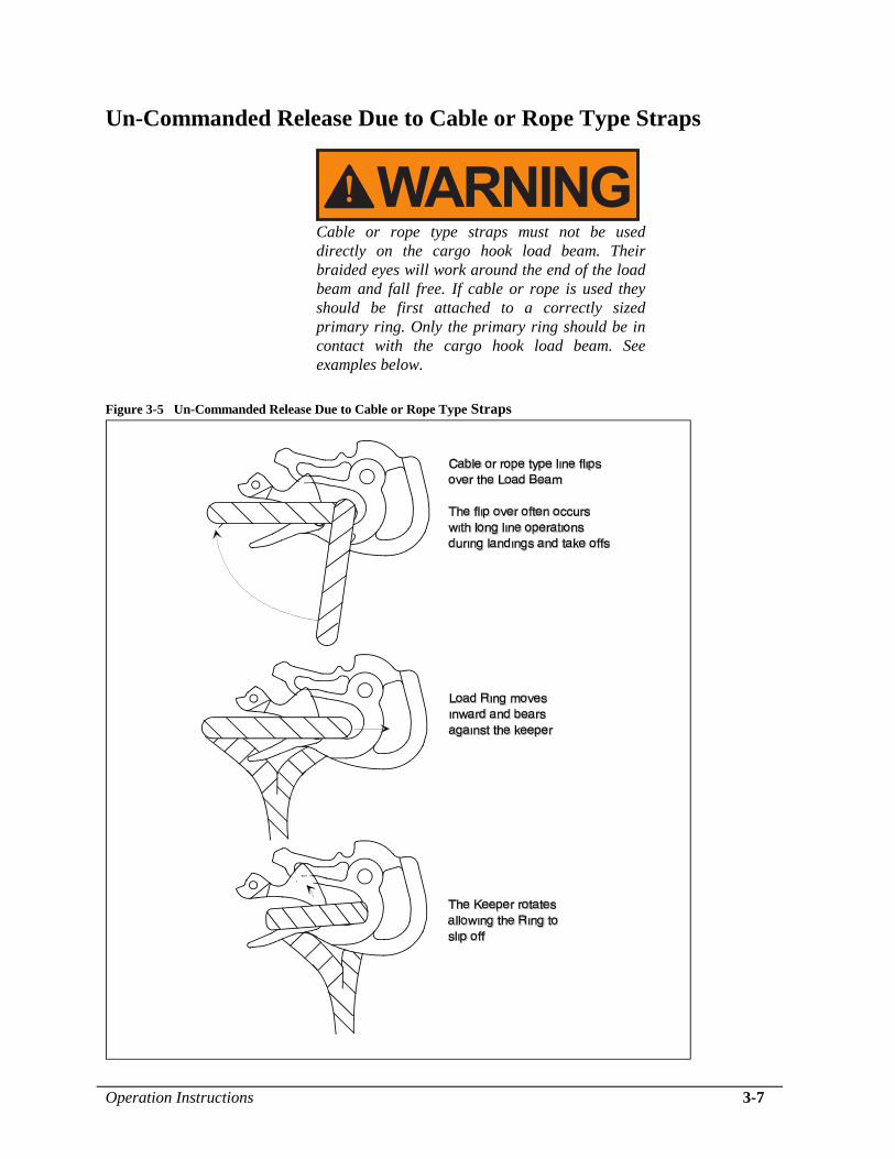
Un-Commanded Release Due to Cable or Rope Type Straps
Cable or rope type straps must not be used
directly on the cargo hook load beam. Their
braided eyes will work around the end of the load
beam and fall free. If cable or rope is used they
should be first attached to a correctly sized
primary ring. Only the primary ring should be in
contact with the cargo hook load beam. See
examples below.
Figure 3-5 Un-Commanded Release Due to Cable or Rope Type Straps

This page intentionally left blank.
Maintenance 4-1
Section 4
Maintenance Refer to Component Maintenance Manual 122-001-00 for detailed
maintenance information for the Cargo Hook.
Instructions for Returning Equipment to the Factory
If an Onboard Systems product must be returned to the factory for any
reason (including returns, service, repairs, overhaul, etc.) obtain an RMA
number before shipping your return.
An RMA number is required for all equipment
returns.
To obtain an RMA, please use one of the listed methods.
Contact Technical Support by phone or e-mail
Generate an RMA number at our website:
http://www.onboardsystems.com/rma.php
After you have obtained the RMA number, please be sure to:
Package the component carefully to ensure safe transit.
Write the RMA number on the outside of the box or on the mailing
label.
Include the RMA number and reason for the return on your
purchase or work order.
Include your name, address, phone and fax number and email (as
applicable).
Return the components freight, cartage, insurance and customs
prepaid to:
Onboard Systems
13915 NW 3rd Court
Vancouver, Washington 98685
USA
Phone: 360-546-3072

This page intentionally left blank.
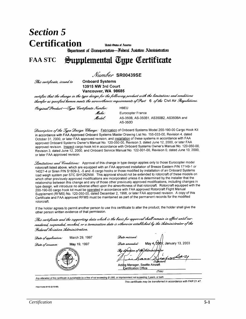
Certification 5-1
Section 5
Certification
FAA STC
5-2 Certification
Canadian STC
Certification 5-3
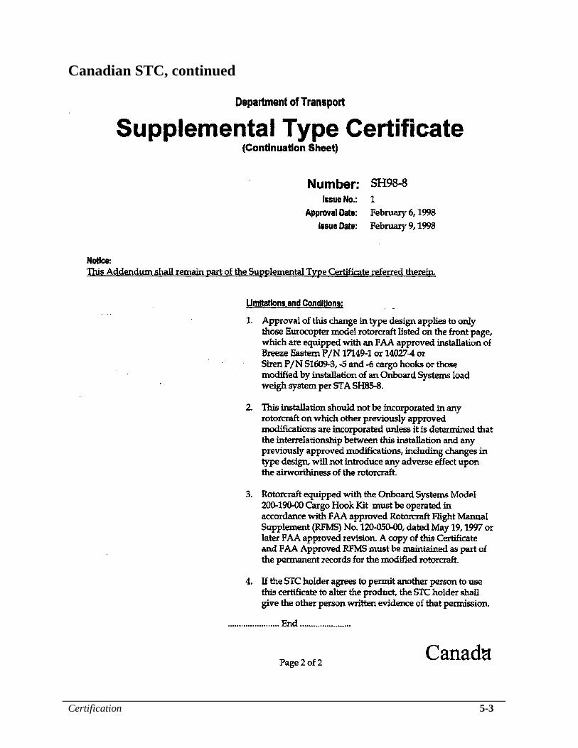
Canadian STC, continued

This page intentionally left blank.
Page 1
Rotorcraft Flight
Manual Supplement
Cargo Hook
Document Number
120-050-00
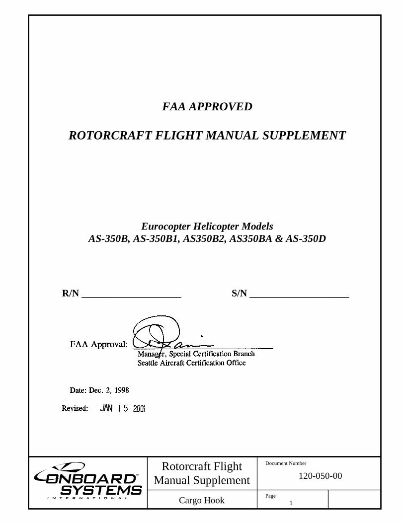
FAA APPROVED
ROTORCRAFT FLIGHT MANUAL SUPPLEMENT
Eurocopter Helicopter Models
AS-350B, AS-350B1, AS350B2, AS350BA & AS-350D
R/N ____________________ S/N ____________________
FAA Approval: _______________________________ Manager, Special Certification Branch
Seattle Aircraft Certification Office
Date: Dec. 2, 1998
Revised:
Page 2
Rotorcraft Flight
Manual Supplement
Cargo Hook
Document Number
120-050-00
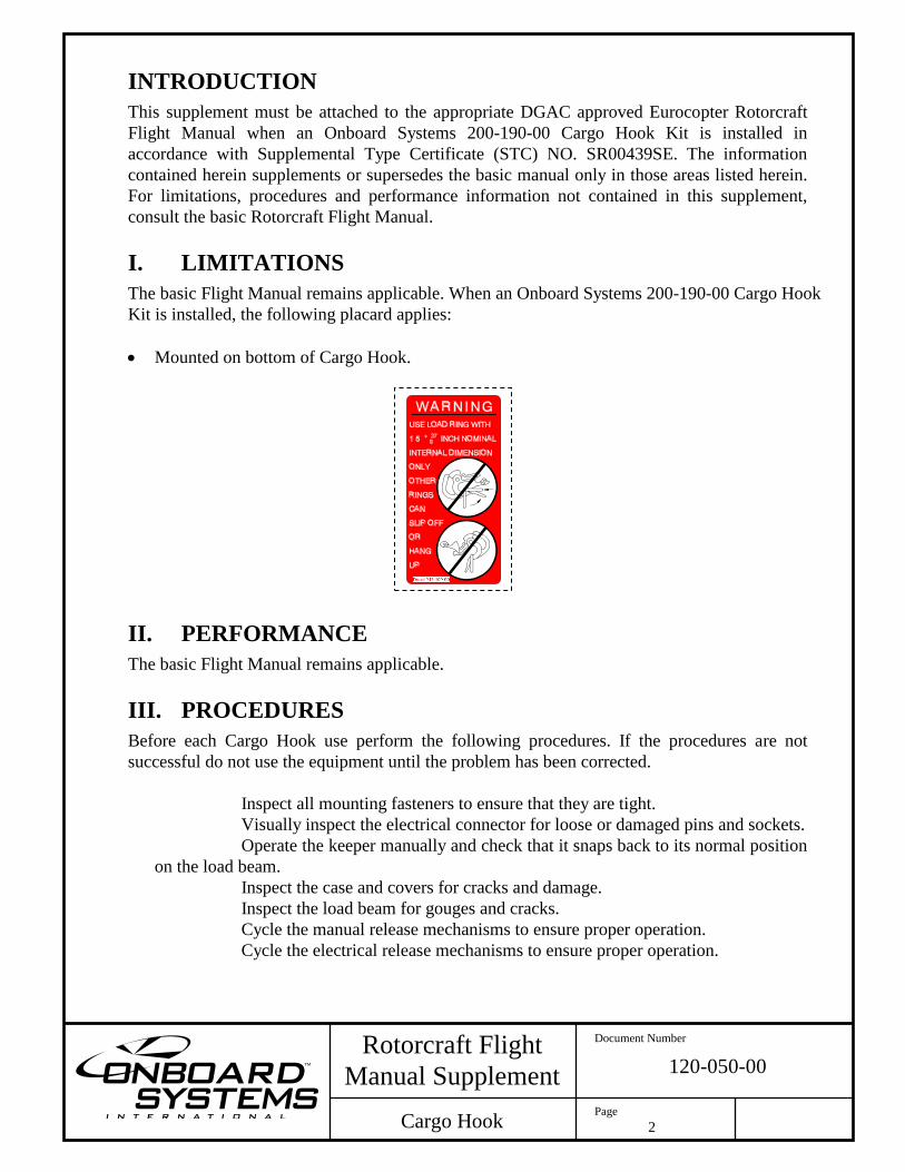
INTRODUCTION
This supplement must be attached to the appropriate DGAC approved Eurocopter Rotorcraft
Flight Manual when an Onboard Systems 200-190-00 Cargo Hook Kit is installed in
accordance with Supplemental Type Certificate (STC) NO. SR00439SE. The information
contained herein supplements or supersedes the basic manual only in those areas listed herein.
For limitations, procedures and performance information not contained in this supplement,
consult the basic Rotorcraft Flight Manual.
I. LIMITATIONS
The basic Flight Manual remains applicable. When an Onboard Systems 200-190-00 Cargo Hook
Kit is installed, the following placard applies:
Mounted on bottom of Cargo Hook.
II. PERFORMANCE
The basic Flight Manual remains applicable.
III. PROCEDURES
Before each Cargo Hook use perform the following procedures. If the procedures are not
successful do not use the equipment until the problem has been corrected.
Inspect all mounting fasteners to ensure that they are tight.
Visually inspect the electrical connector for loose or damaged pins and sockets.
Operate the keeper manually and check that it snaps back to its normal position
on the load beam.
Inspect the case and covers for cracks and damage.
Inspect the load beam for gouges and cracks.
Cycle the manual release mechanisms to ensure proper operation.
Cycle the electrical release mechanisms to ensure proper operation.
Page 3
Rotorcraft Flight
Manual Supplement
Cargo Hook
Document Number
120-050-00
III. PROCEDURES, continued
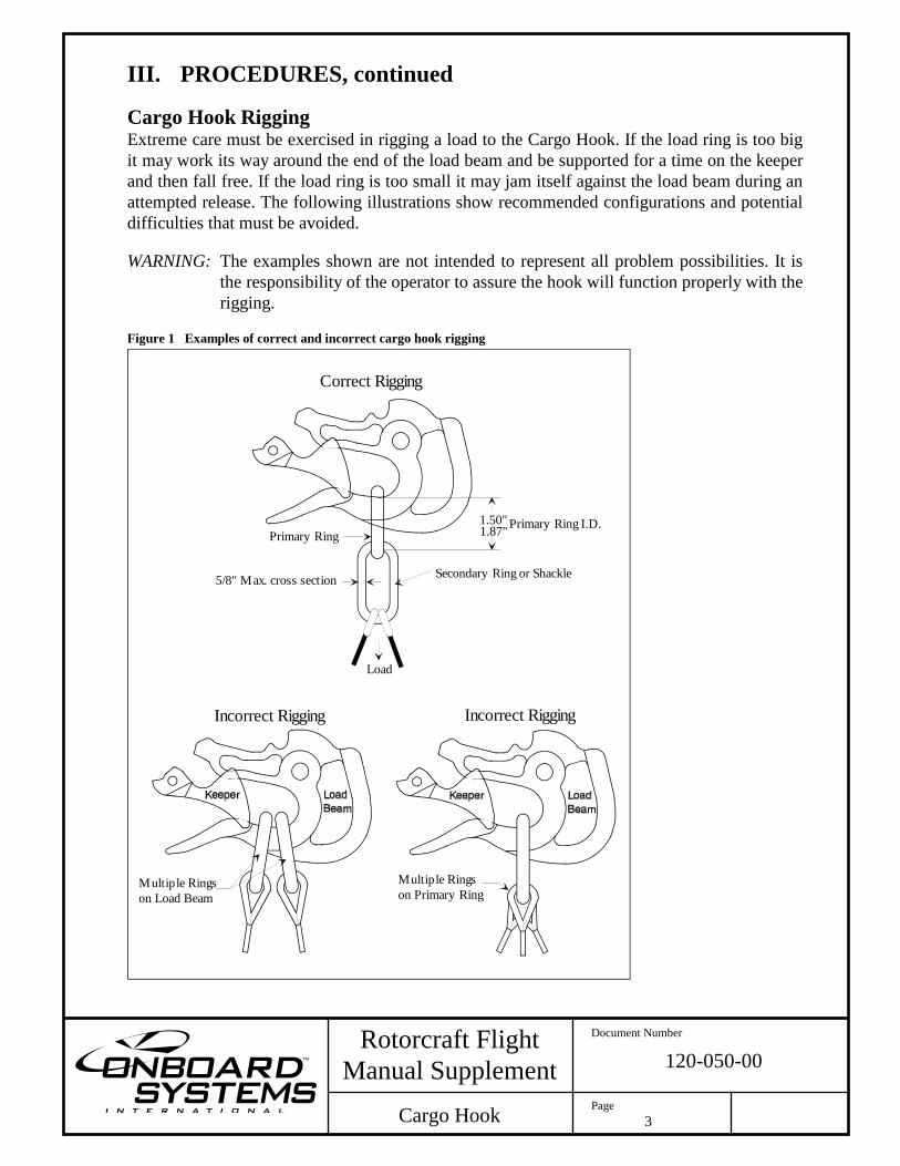
Cargo Hook Rigging Extreme care must be exercised in rigging a load to the Cargo Hook. If the load ring is too big
it may work its way around the end of the load beam and be supported for a time on the keeper
and then fall free. If the load ring is too small it may jam itself against the load beam during an
attempted release. The following illustrations show recommended configurations and potential
difficulties that must be avoided.
WARNING: The examples shown are not intended to represent all problem possibilities. It is
the responsibility of the operator to assure the hook will function properly with the
rigging. Figure 1 Examples of correct and incorrect cargo hook rigging
Secondary Ring or Shackle5/8" Max. cross section
Load
Primary Ring
Incorrect Rigging Incorrect Rigging
Correct Rigging
Multiple Rings
on Load Beam
Multiple Rings
on Primary Ring
1.50" Primary Ring I.D.1.87"
Page 4
Rotorcraft Flight
Manual Supplement
Cargo Hook
Document Number
120-050-00
III. PROCEDURES, continued
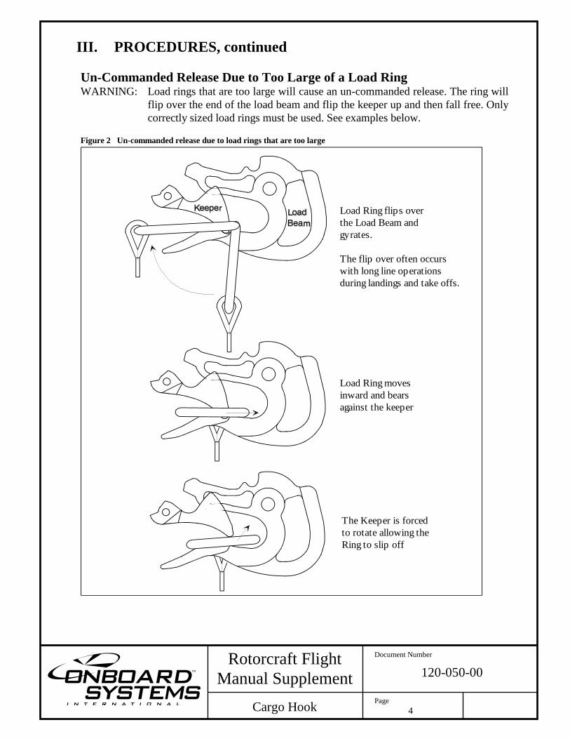
Un-Commanded Release Due to Too Large of a Load Ring WARNING: Load rings that are too large will cause an un-commanded release. The ring will
flip over the end of the load beam and flip the keeper up and then fall free. Only
correctly sized load rings must be used. See examples below. Figure 2 Un-commanded release due to load rings that are too large
Load Ring flips over
the Load Beam and
gyrates.
The flip over often occurs
with long line operations
during landings and take offs.
Load Ring moves
inward and bears
against the keeper
The Keeper is forced
to rotate allowing the
Ring to slip off
Page 5
Rotorcraft Flight
Manual Supplement
Cargo Hook
Document Number
120-050-00
III. PROCEDURES, continued
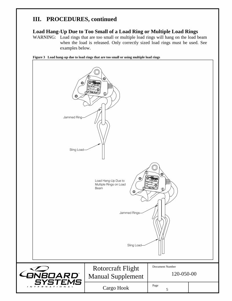
Load Hang-Up Due to Too Small of a Load Ring or Multiple Load Rings WARNING: Load rings that are too small or multiple load rings will hang on the load beam
when the load is released. Only correctly sized load rings must be used. See
examples below. Figure 3 Load hang-up due to load rings that are too small or using multiple load rings
Jammed Ring
Sling Load
Sling Load
Jammed Rings
Load Hang-Up Due to
Multiple Rings on Load
Beam
Page 6
Rotorcraft Flight
Manual Supplement
Cargo Hook
Document Number
120-050-00
III. PROCEDURES, continued
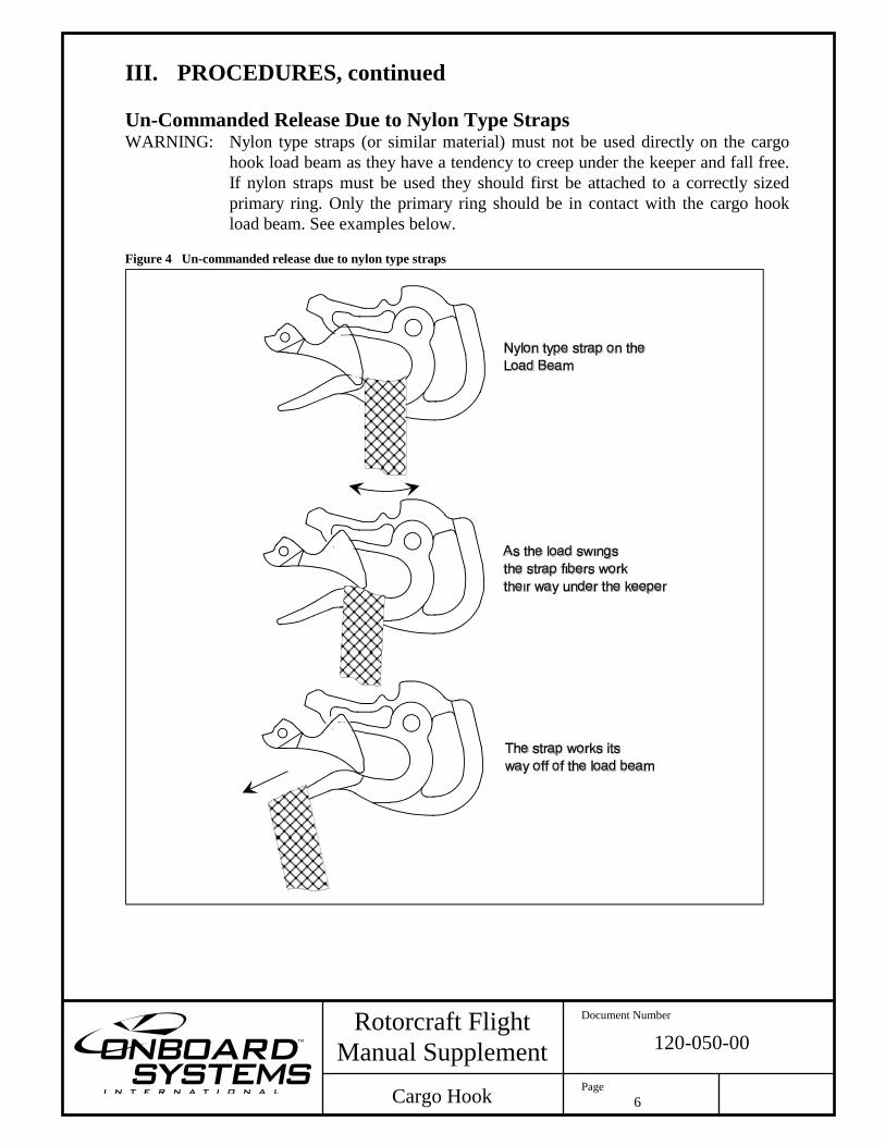
Un-Commanded Release Due to Nylon Type Straps WARNING: Nylon type straps (or similar material) must not be used directly on the cargo
hook load beam as they have a tendency to creep under the keeper and fall free.
If nylon straps must be used they should first be attached to a correctly sized
primary ring. Only the primary ring should be in contact with the cargo hook
load beam. See examples below. Figure 4 Un-commanded release due to nylon type straps
Page 7
Rotorcraft Flight
Manual Supplement
Cargo Hook
Document Number
120-050-00
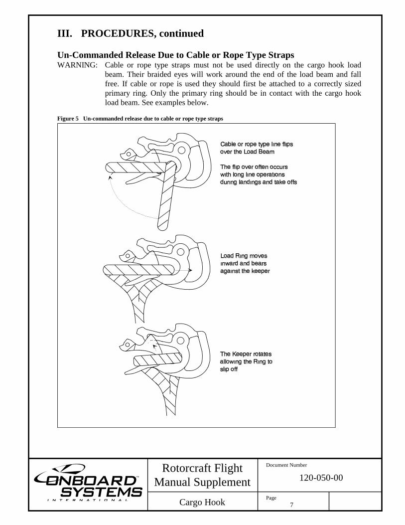
III. PROCEDURES, continued
Un-Commanded Release Due to Cable or Rope Type Straps WARNING: Cable or rope type straps must not be used directly on the cargo hook load
beam. Their braided eyes will work around the end of the load beam and fall
free. If cable or rope is used they should first be attached to a correctly sized
primary ring. Only the primary ring should be in contact with the cargo hook
load beam. See examples below. Figure 5 Un-commanded release due to cable or rope type straps

This page intentionally left blank.