Embed Size (px)
Citation preview
TSINGHUA SCIENCE AND TECHNOLOGY ISSNll1007-0214ll05/09llpp505-519 Volume 16, Number 5, October 2011
Forced Collision: Detecting Wormhole Attacks with Physical Layer Network Coding*
Zhiwei Li, Di Pu†, Weichao Wang**, Alex Wyglinski†
Department of Software & Information Systems, UNC Charlotte, 9201 Univ. City Blvd, Charlotte, NC 28223, USA; † Department of Electrical & Computer Engineering, Worcester Polytechnic Institute, 100 Institute Road,
Worcester, MA 01609, USA
Abstract: Previous research on security of network coding focused on the protection of data dissemination
procedures and the detection of malicious activities such as pollution attacks. The capabilities of network
coding to detect other attacks have not been fully explored. In this paper, we propose a new mechanism
based on physical layer network coding to detect wormhole attacks. When two signal sequences collide at
the receiver, the starting point of the collision is determined by the distances between the receiver and the
senders. Therefore, by comparing the starting points of the collisions at two receivers, we can estimate the
distance between them and detect fake neighbor connections via wormholes. While the basic idea is clear,
we have proposed several schemes at both physical and network layers to transform the idea into a
practical approach. Simulations using BPSK modulation at the physical layer show that the wireless nodes
can effectively detect fake neighbor connections without the adoption of special hardware or time
synchronization.
Key words: physical layer network coding; wormhole attacks; cross-layer design
Introduction
Investigators have proposed the physical layer network coding technique[1,2] to fully explore the advantages such as improved throughput, reduced congestion, and strengthened robustness. The technique is especially valuable in wireless networks when we consider the limited bandwidth and power resources of the nodes. Since network coding may allow data errors and/or corrupted packets to propagate widely and ruin the data recovery procedure at the final destination, previ-ous research into network coding security focused on the protection of data dissemination procedures and the detection of malicious activities such as pollution
attacks[3,4]. However, the security capabilities of physical layer
network coding to detect malicious attacks have not been fully explored. For instance, it is possible that when signals collide at the receiver, we can potentially extract information about the network structure. This information can then be used to detect attacks on net-work topology. In this paper, we conduct an investiga-tion of this problem. Specifically, we propose a new mechanism to detect wormhole attacks.
Several reasons lead us to choose wormhole attacks as the primary research topic for this investigation. First, wormhole attacks impose severe threats to the correct detection of network topology, which is the foundation of various operations within wireless net-works such as routing and data transmission. Second, a wormhole attack is a representation of stealth attacks on wireless networks, where traditional methods such
Received: 2011-06-21; revised: 2011-08-29
** Supported in part by the NSF CNS Award (No. 1143602) ** To whom correspondence should be addressed.
E-mail: [email protected]
Tsinghua Science and Technology, October 2011, 16(5): 505-519
506
as encryption and authentication cannot defend against such attacks. Therefore, a detection method based on physical layer network coding will allow us to better understand this problem. Finally, previous approaches for detecting wormhole attacks are usually imple-mented at the network layer. Our proposed approach uses physical layer properties. At the same time, our approach does not require time synchronization among wireless nodes or depend on any special hardware.
The basic idea of our proposed approach is as fol-lows: when the long sequences from two senders col-lide at the receiver, the starting point of the collision between the sequences is jointly determined by the sending time and the physical distances across all the receiver and senders. For two receivers, their starting points of collision will be different, and this difference is restricted by the physical distance between them. Therefore, through measuring and comparing the overlapping parts of the received sequences, we can estimate the physical distance between two wireless nodes and detect the fake connection between them. Since the proposed approach only measures the start-ing point of the collision in the sequences, we do not need time synchronization among the wireless nodes. Our analysis will also show that the physical distances among the senders and receivers will not impact the detection results. Therefore, we can choose the senders from a large area within the network.
Although the basic idea of the proposed approach is clear, we need to design schemes at both physical layer and network layer to make the approach practical. At the network layer, we need to determine the senders and their data sequences. Mechanisms must be de-signed to prevent the man-in-the-middle attack. At the same time, the receivers need a scheme to verify the authenticity of the recovered sequences from collisions. At the physical layer, we need to carefully select data transmission parameters such as modulation and car-rier frequency. Consequently, algorithms are designed to recover the received sequences. We will also inves-tigate the impacts of different factors, such as phase shift and carrier frequency jitter, on the proposed ap-proach using both analysis and simulation.
Our investigation has the following contributions: • We make an attempt to explore the security capa-
bilities of the physical layer network coding technique. The research will demonstrate that in addition to
improving the bandwidth efficiency and data robust-ness in wireless networks, physical layer network cod-ing can also be used to detect malicious attacks. This research provides a new incentive for further develop-ment of this technique.
• The proposed wormhole detection mechanism does not require any special hardware or time synchro-nization in the wireless network. Therefore, existing systems can easily adopt the proposed approach with-out going through drastic structural and functional changes.
• We carefully design schemes in both network layer and physical layer to make the approach practical. Impacts of different factors in the communication channel are studied through theoretic analysis and simulation.
The remainder of the paper is organized as follows: in Section 1, we introduce the basic idea of the detec-tion mechanism and the role of physical layer network coding in wormhole detection. Section 2 reviews the related work. Sections 3 and 4 design mechanisms in the network layer and in the physical layer to make the approach secure and practical. We perform both an analysis and simulations to investigate the impacts of different factors in the physical layer. In Section 5 we study the security and detection accuracy of the pro-posed approach. Finally, Section 6 concludes the paper.
1 The Basic Idea
In this part, we introduce the basic idea of using physical layer network coding to detect wormhole at-tacks. We assume that two wireless nodes are neighbors if and only if the distance between them is shorter than .r However, this assumption does not restrict wireless nodes from transmitting signals at a higher power level in order to reach a longer distance. We assume the attackers are not capable of compro-mising any wireless nodes within the network. How-ever, they can deploy their own nodes to eavesdrop on the traffic, tunnel the packets, and retransmit the data. In the following analysis, we use MNd to represent the physical distance between two nodes M and .N We use T to represent a specific moment and t to represent a time duration. If the radio signal propagates at the speed of light s , the transmission delay between
two nodes M and N will be MNds
. In the following
Zhiwei Li et al.:Forced Collision: Detecting Wormhole Attacks with Physical … 507
analysis, we describe the time difference between the received sequences. We are not using the system clocks to directly measure the actual time. On the contrary, we can pinpoint the starting bit in the sequence that the collision starts. Then we can translate this information into a time difference. This topic is discussed further in Section 5.1.
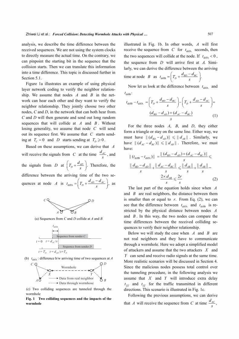
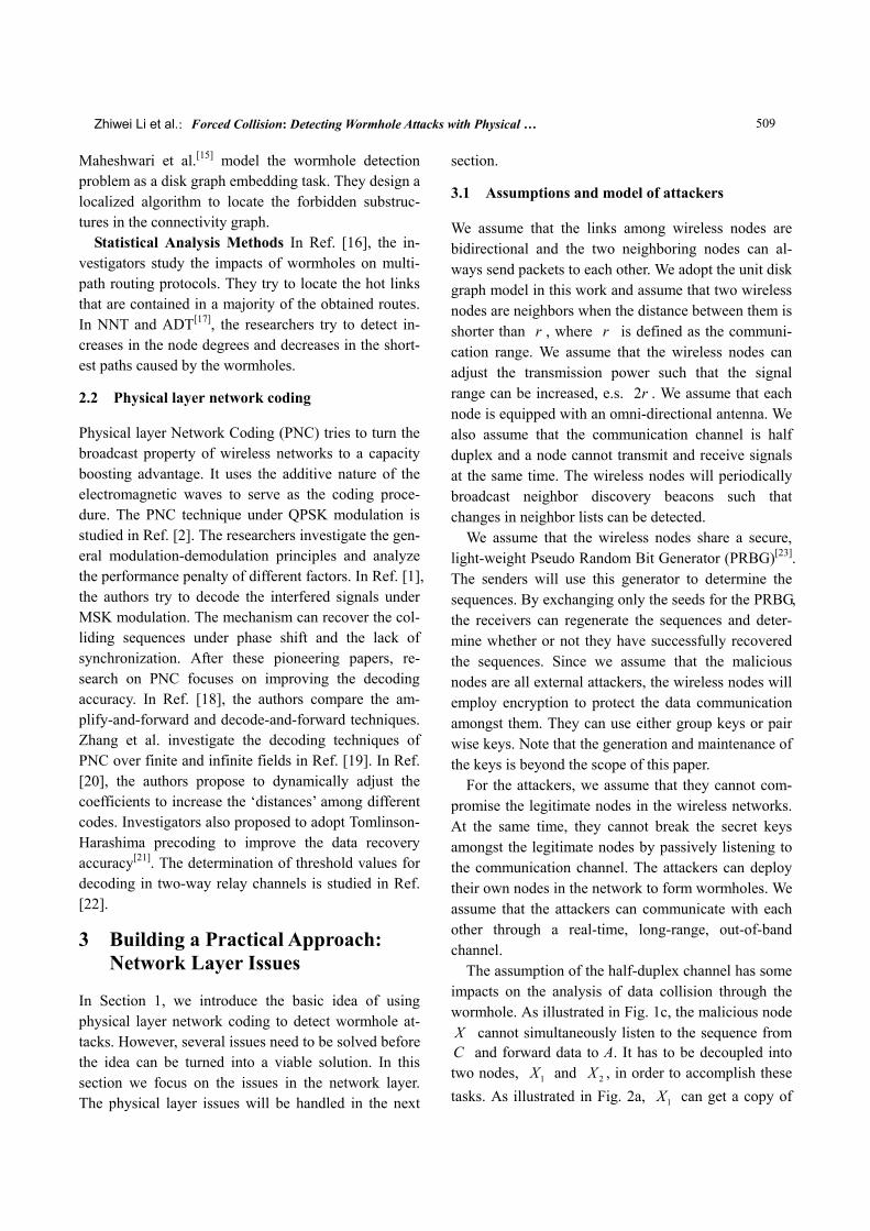
Figure 1a illustrates an example of using physical layer network coding to verify the neighbor relation-ship. We assume that nodes A and B in the net-work can hear each other and they want to verify the neighbor relationship. They jointly choose two other nodes, C and D, in the network that can both hear from. C and D will then generate and send out long random sequences that will collide at A and B . Without losing generality, we assume that node C will send out its sequence first. We assume that C starts send-ing at 0CT = and D starts sending at 0DT .
Based on these assumptions, we can derive that A
will receive the signals from C at the time ACds , and
the signals from D at ADD
dT s⎛ ⎞+⎜ ⎟⎝ ⎠
. Therefore, the
difference between the arriving time of the two se-
quences at node A is diffAAD AC
Dd d
t T s−⎛ ⎞= +⎜ ⎟
⎝ ⎠, as
illustrated in Fig. 1b. In other words, A will first receive the sequence from C for diffAt seconds, then the two sequences will collide at the node. If diffA 0t < , the sequence from D will arrive first at .A Simi-larly, we can derive the difference between the arriving
time at node B as diffBBD BC
Dd d
t Ts−⎛ ⎞= +⎜ ⎟
⎝ ⎠.
Now let us look at the difference between diffAt and
diffBt :
diffB diffAt t− BD BC AD ACD D
d d d dT T
s s− −⎛ ⎞ ⎛ ⎞= + − + =⎜ ⎟ ⎜ ⎟
⎝ ⎠ ⎝ ⎠
( ) ( )BD AD AC BCd d d ds
− + − (1)
For the three nodes ,A ,B and ,D they either form a triangle or stay on the same line. Either way, we must have ( )BD ADd d|| − || ABd|| || . Similarly, we have ( )AC BCd d|| − || ABd|| || . Therefore, we must have:
diffB diffA( )t t|| − ||( ) ( )BD AD AC BCd d d d
s|| − + − ||
=
AC BCBD AD d dd ds s
|| − |||| − ||+ =AB ABd d
s s|| || || ||
+
2 2ABd rs s
× (2)
The last part of the equation holds since when A and B are real neighbors, the distance between them is smaller than or equal to .r From Eq. (2), we can see that the difference between diffAt and diffBt is re-stricted by the physical distance between nodes A and B . In this way, the two nodes can compare the time differences between the received colliding se-quences to verify their neighbor relationship.
Below we will study the case when A and B are not real neighbors and they have to communicate through a wormhole. Here we adopt a simplified model of attackers and assume that the two attackers X and Y can send and receive radio signals at the same time. More realistic scenarios will be discussed in Section 4. Since the malicious nodes possess total control over the tunneling procedure, in the following analysis we assume that X and Y will introduce extra delay
XYt and YXt for the traffic transmitted in different directions. This scenario is illustrated in Fig. 1c.
Following the previous assumptions, we can derive
that A will receive the sequence from C at time ,ACds
(a) Sequences from C and D collide at A and B
(b) diffAt : difference b/w arriving time of two sequences at A
(c) Two colliding sequences are tunneled through the wormhole Fig. 1 Two colliding sequences and the impacts of the wormhole
Tsinghua Science and Technology, October 2011, 16(5): 505-519
508
and the sequence from D at time DT⎛ +⎜⎝
DY XY AXYX
d d d ts+ + ⎞+ ⎟
⎠. Similarly, B will receive the
sequence from C at time CX XY BYXY
d d dt s+ +⎛ ⎞+⎜ ⎟
⎝ ⎠,
and the sequence from D at time ( )BDD
dT s+ . There-
fore, we have
diffA diffBt t− ( )DY BY BDXY YX
d d dt ts
+ −= + + +
( ) 2AX CX AC XYd d d ds s
+ −+ × (3)
Since the three nodes ,A ,C and X either form a triangle or are on the same line, we must have ( ) 0.AX CX ACd d d+ − Similarly, we have ( DY BYd d+ −
) 0BDd . The extra transmission delay XYt and YXt introduced by the malicious nodes cannot be smaller than 0. Therefore, we have
diffA diffB 2 XYdt ts
⎛ ⎞|| − || ×⎜ ⎟⎝ ⎠
(4)
When the length of the wormhole XYd is longer than the radio transmission range ,r we have
diffA diffB2rt ts
|| − || > . Combining the results in Eqs. (2)
and (4), we find that two nodes in the wireless network can verify their neighbor relationship by comparing the differences between the starting points of collision in the received sequences.
The proposed approach has several highly desirable properties. First, since the mechanism uses only the starting points of the collision between the sequences to detect wormholes, we do not need the senders or receivers to synchronize their clocks. As illustrated in Eqs. (2) and (4), the parameter DT has been canceled out. Second, in Eq. (2) the physical distances between the senders and the receivers have also been canceled out. The difference is determined only by the physical distance between the nodes that want to verify their neighbor relationship. This implies that we can choose the senders from a large area in the network, and they do not need to be direct neighbors of A and .B Third, the proposed mechanism does not require the wireless nodes to be equipped with any special hard-ware which will result in a lower node cost. The capa-bilities of the nodes to recover colliding sequences will be discussed in Section 4. Finally, the proposed
approach works in a distributed manner and does not require a centralized controller. Nodes A and B can determine their senders and exchange diffAt and
diffBt to detect wormholes. With these desirable prop-erties, the approach can be easily adopted by existing networks.
2 Related Work
2.1 Wormhole detection
Location and Time Based Solutions This group of solutions try to restrict the transmission range of a packet by measuring the time and/or positions of the wireless nodes. For example, packet leash is proposed by Hu et al.[5] for wormhole prevention. The geo-graphic leashes and temporal leashes use location in-formation and signal propagation delay respectively to verify a neighbor relation. In SECTOR[6], the wireless nodes use a special hardware to respond to a one-bit challenge. The challenger measures the round trip time to estimate the distance between the nodes. Using di-rectional antenna[7], the neighbor relation between two nodes can be verified based on the directions of the received signals. In LiteWorp[8], the wireless nodes use the short safe period after deployment to detect the real 1-hop and 2-hop neighbors. They will then monitor the packet forwarding actions to detect wormholes. The improved approach[9] for wormhole detection in mo-bile wireless networks requires the nodes to have GPS and loosely synchronized clocks. The EDWA[10] method also requires the wireless nodes to be equipped with GPS. In TrueLink[11], the wireless nodes strictly follow the 802.11 standard of the time interval between packets to restrict their transmission distances. It re-quires the wireless nodes to have very accurate clocks.
Graph Based Approaches Investigators have tried to detect wormholes based on their impacts on the network topology. MDS-VoW[12] is a centralized mechanism for wormhole detection in sensor networks. It reconstructs the layout of sensors using multi-di-mensional scaling and detects wormholes by visualiz-ing the anomalies introduced by the attacks. A decen-tralized approach for dynamic networks is proposed in Ref. [13]. In Ref. [14], the researchers analyze the geometric random graphs induced by the communica-tion range constraint of the nodes. They present a de-fense mechanism based on local broadcast keys.
Zhiwei Li et al.:Forced Collision: Detecting Wormhole Attacks with Physical … 509
Maheshwari et al.[15] model the wormhole detection problem as a disk graph embedding task. They design a localized algorithm to locate the forbidden substruc-tures in the connectivity graph.
Statistical Analysis Methods In Ref. [16], the in-vestigators study the impacts of wormholes on multi- path routing protocols. They try to locate the hot links that are contained in a majority of the obtained routes. In NNT and ADT[17], the researchers try to detect in-creases in the node degrees and decreases in the short-est paths caused by the wormholes.
2.2 Physical layer network coding
Physical layer Network Coding (PNC) tries to turn the broadcast property of wireless networks to a capacity boosting advantage. It uses the additive nature of the electromagnetic waves to serve as the coding proce-dure. The PNC technique under QPSK modulation is studied in Ref. [2]. The researchers investigate the gen-eral modulation-demodulation principles and analyze the performance penalty of different factors. In Ref. [1], the authors try to decode the interfered signals under MSK modulation. The mechanism can recover the col-liding sequences under phase shift and the lack of synchronization. After these pioneering papers, re-search on PNC focuses on improving the decoding accuracy. In Ref. [18], the authors compare the am-plify-and-forward and decode-and-forward techniques. Zhang et al. investigate the decoding techniques of PNC over finite and infinite fields in Ref. [19]. In Ref. [20], the authors propose to dynamically adjust the coefficients to increase the ‘distances’ among different codes. Investigators also proposed to adopt Tomlinson- Harashima precoding to improve the data recovery accuracy[21]. The determination of threshold values for decoding in two-way relay channels is studied in Ref. [22].
3 Building a Practical Approach: Network Layer Issues
In Section 1, we introduce the basic idea of using physical layer network coding to detect wormhole at-tacks. However, several issues need to be solved before the idea can be turned into a viable solution. In this section we focus on the issues in the network layer. The physical layer issues will be handled in the next
section.
3.1 Assumptions and model of attackers
We assume that the links among wireless nodes are bidirectional and the two neighboring nodes can al-ways send packets to each other. We adopt the unit disk graph model in this work and assume that two wireless nodes are neighbors when the distance between them is shorter than r , where r is defined as the communi-cation range. We assume that the wireless nodes can adjust the transmission power such that the signal range can be increased, e.s. 2r . We assume that each node is equipped with an omni-directional antenna. We also assume that the communication channel is half duplex and a node cannot transmit and receive signals at the same time. The wireless nodes will periodically broadcast neighbor discovery beacons such that changes in neighbor lists can be detected.
We assume that the wireless nodes share a secure, light-weight Pseudo Random Bit Generator (PRBG)[23]. The senders will use this generator to determine the sequences. By exchanging only the seeds for the PRBG, the receivers can regenerate the sequences and deter-mine whether or not they have successfully recovered the sequences. Since we assume that the malicious nodes are all external attackers, the wireless nodes will employ encryption to protect the data communication amongst them. They can use either group keys or pair wise keys. Note that the generation and maintenance of the keys is beyond the scope of this paper.
For the attackers, we assume that they cannot com-promise the legitimate nodes in the wireless networks. At the same time, they cannot break the secret keys amongst the legitimate nodes by passively listening to the communication channel. The attackers can deploy their own nodes in the network to form wormholes. We assume that the attackers can communicate with each other through a real-time, long-range, out-of-band channel.
The assumption of the half-duplex channel has some impacts on the analysis of data collision through the wormhole. As illustrated in Fig. 1c, the malicious node X cannot simultaneously listen to the sequence from C and forward data to A. It has to be decoupled into two nodes, 1X and 2X , in order to accomplish these tasks. As illustrated in Fig. 2a, 1X can get a copy of
Tsinghua Science and Technology, October 2011, 16(5): 505-519
510
the data that 2X is transmitting through the out-of- band channel. Therefore, 1X will be able to decode the sequence from C in the presence of interference. Decoupling the node X into two nodes will intro-duce some changes to Eq. (4). However, these changes can be hidden in the transmission delay of the worm-hole and will not subvert our approach.
3.2 Selection of senders
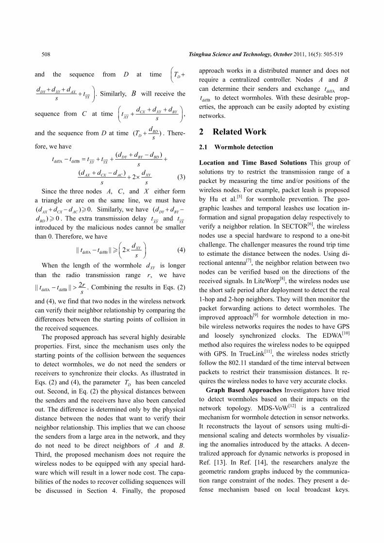
In this part we study two problems: first, how to choose the senders in a real network environment; second, the relationship between the wormhole detec-tion probability and the number of rounds of verifica-tion. Answers to these questions will allow us to better understand the advantages and limitations of the pro-posed approach. 3.2.1 Selection of senders The analysis in Section 1 showed that the detection of wormholes will not be impacted by the distances among the senders and receivers. However, in a real wireless network, several reasons restrict us from choosing a sender that is multiple hops away from the receiver. First, if the sender is far away from the re-ceivers, it has to transmit the signal at a high power level. This will not only consume the limited battery power of the sender but it will also cause interference in a large area. Second, if we choose a sender that is multiple hops away, this path has a higher probability to contain a wormhole. The malicious nodes can then manipulate the arriving time of the sequences and compromise the detection mechanism. Therefore, we propose to choose the senders from the union of the neighbor lists of the receivers.
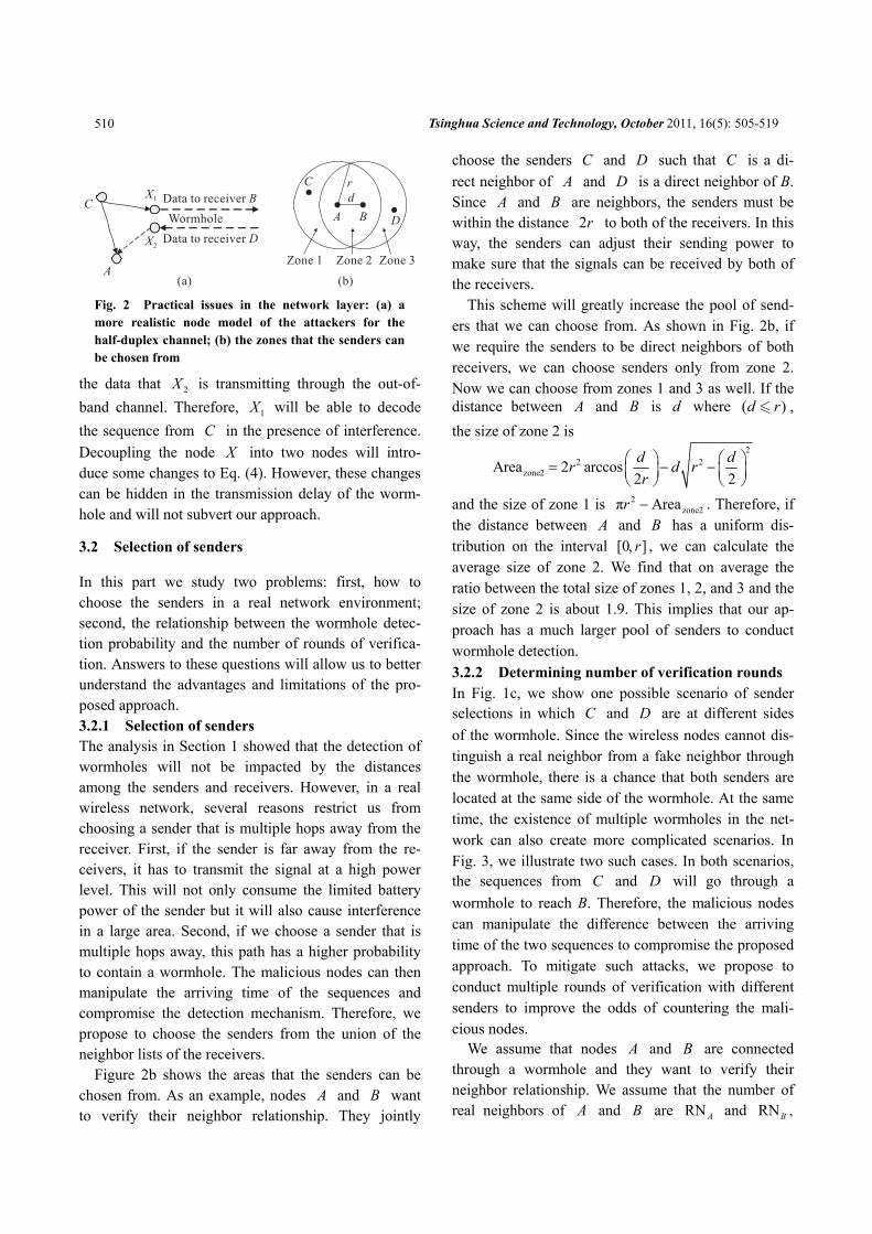
Figure 2b shows the areas that the senders can be chosen from. As an example, nodes A and B want to verify their neighbor relationship. They jointly
choose the senders C and D such that C is a di-rect neighbor of A and D is a direct neighbor of B. Since A and B are neighbors, the senders must be within the distance 2r to both of the receivers. In this way, the senders can adjust their sending power to make sure that the signals can be received by both of the receivers.
This scheme will greatly increase the pool of send-ers that we can choose from. As shown in Fig. 2b, if we require the senders to be direct neighbors of both receivers, we can choose senders only from zone 2. Now we can choose from zones 1 and 3 as well. If the distance between A and B is d where ( )d r , the size of zone 2 is
22 2
zone2Area 2 arccos2 2d dr d rr
⎛ ⎞ ⎛ ⎞= − −⎜ ⎟ ⎜ ⎟⎝ ⎠ ⎝ ⎠
and the size of zone 1 is 2zone2π Arear − . Therefore, if
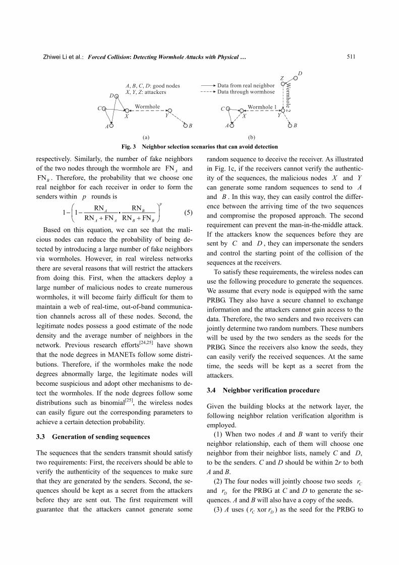
the distance between A and B has a uniform dis-tribution on the interval [0 ]r, , we can calculate the average size of zone 2. We find that on average the ratio between the total size of zones 1, 2, and 3 and the size of zone 2 is about 1.9. This implies that our ap-proach has a much larger pool of senders to conduct wormhole detection. 3.2.2 Determining number of verification rounds In Fig. 1c, we show one possible scenario of sender selections in which C and D are at different sides of the wormhole. Since the wireless nodes cannot dis-tinguish a real neighbor from a fake neighbor through the wormhole, there is a chance that both senders are located at the same side of the wormhole. At the same time, the existence of multiple wormholes in the net-work can also create more complicated scenarios. In Fig. 3, we illustrate two such cases. In both scenarios, the sequences from C and D will go through a wormhole to reach B. Therefore, the malicious nodes can manipulate the difference between the arriving time of the two sequences to compromise the proposed approach. To mitigate such attacks, we propose to conduct multiple rounds of verification with different senders to improve the odds of countering the mali-cious nodes.
We assume that nodes A and B are connected through a wormhole and they want to verify their neighbor relationship. We assume that the number of real neighbors of A and B are RNA and RNB ,
Fig. 2 Practical issues in the network layer: (a) a more realistic node model of the attackers for the half-duplex channel; (b) the zones that the senders can be chosen from
Zhiwei Li et al.:Forced Collision: Detecting Wormhole Attacks with Physical … 511
Fig. 3 Neighbor selection scenarios that can avoid detection
respectively. Similarly, the number of fake neighbors of the two nodes through the wormhole are FNA and FNB . Therefore, the probability that we choose one real neighbor for each receiver in order to form the senders within p rounds is
RN RN1 1RN FN RN FN
p
A B
A A B B
⎛ ⎞− −⎜ ⎟+ +⎝ ⎠
∙ (5)
Based on this equation, we can see that the mali-cious nodes can reduce the probability of being de-tected by introducing a large number of fake neighbors via wormholes. However, in real wireless networks there are several reasons that will restrict the attackers from doing this. First, when the attackers deploy a large number of malicious nodes to create numerous wormholes, it will become fairly difficult for them to maintain a web of real-time, out-of-band communica-tion channels across all of these nodes. Second, the legitimate nodes possess a good estimate of the node density and the average number of neighbors in the network. Previous research efforts[24,25] have shown that the node degrees in MANETs follow some distri-butions. Therefore, if the wormholes make the node degrees abnormally large, the legitimate nodes will become suspicious and adopt other mechanisms to de-tect the wormholes. If the node degrees follow some distributions such as binomial[25], the wireless nodes can easily figure out the corresponding parameters to achieve a certain detection probability.
3.3 Generation of sending sequences
The sequences that the senders transmit should satisfy two requirements: First, the receivers should be able to verify the authenticity of the sequences to make sure that they are generated by the senders. Second, the se-quences should be kept as a secret from the attackers before they are sent out. The first requirement will guarantee that the attackers cannot generate some
random sequence to deceive the receiver. As illustrated in Fig. 1c, if the receivers cannot verify the authentic-ity of the sequences, the malicious nodes X and Y can generate some random sequences to send to A and B . In this way, they can easily control the differ-ence between the arriving time of the two sequences and compromise the proposed approach. The second requirement can prevent the man-in-the-middle attack. If the attackers know the sequences before they are sent by C and D , they can impersonate the senders and control the starting point of the collision of the sequences at the receivers.
To satisfy these requirements, the wireless nodes can use the following procedure to generate the sequences. We assume that every node is equipped with the same PRBG. They also have a secure channel to exchange information and the attackers cannot gain access to the data. Therefore, the two senders and two receivers can jointly determine two random numbers. These numbers will be used by the two senders as the seeds for the PRBG. Since the receivers also know the seeds, they can easily verify the received sequences. At the same time, the seeds will be kept as a secret from the attackers.
3.4 Neighbor verification procedure
Given the building blocks at the network layer, the following neighbor relation verification algorithm is employed.
(1) When two nodes A and B want to verify their neighbor relationship, each of them will choose one neighbor from their neighbor lists, namely C and ,D to be the senders. C and D should be within 2r to both A and B.
(2) The four nodes will jointly choose two seeds Cr and Dr for the PRBG at C and D to generate the se-quences. A and B will also have a copy of the seeds.
(3) A uses ( xorC Dr r ) as the seed for the PRBG to
Tsinghua Science and Technology, October 2011, 16(5): 505-519
512
generate a series of pilot bits. A will broadcast the pilot bits at the power level such that B, C, and D will all receive the data to learn that the verification procedure starts.
(4) C and D will verify the pilot bits from A. Each of them will then choose a random delay to make sure that A and B are ready to receive. Then, the two nodes will send out the sequences generated by the PRBG based on the seeds Cr and Dr . They will send the sequences with a sufficiently high power level such that both A and B can receive them. The two sequences will be long enough such that a large part of the se-quences will collide at the receivers.
(5) A and B will use the algorithm in Section 4 to separate the sequences and verify them. The two nodes will exchange the starting points of the collisions and use the method described in Section 1 to verify their neighbor relationship.
(6) Steps 1 to 5 will repeat until A and B find that they are connected through a wormhole or they are convinced that they are real neighbors after p rounds.
4 Building a Practical Approach: Physical Layer Issues
To turn the proposed approach into a practical solution, the physical layer needs to accomplish the following tasks. First, the physical layer needs to successfully separate the two interfered sequences. It also needs to locate the starting point of the collision so that the in-formation can be used to detect wormholes. Second, we need to assess the impacts of different factors in the physical layer on the proposed approach. In the fol-lowing subsections, we will determine the parameters for signal transmission, design the receiver algorithm to separate the colliding sequences, and evaluate the approach under different parameters through theoreti-cal analysis and simulation.
4.1 Modulation of signals
When the two senders generate their sequences using the PRBG, the data bits need to be modulated and de-modulated in order to achieve over-the-air transmission. Thus, we need to decide on a proper modulation/ demodulation scheme on both ends. 4.1.1 Binary Phase Shift Keying (BPSK) Phase-Shift Keying (PSK) is a digital modulation
scheme that conveys data by modulating the phase of the carrier wave. Since any digital modulation scheme uses a finite number of distinct signals to represent digital data, PSK uses a finite number of phases that are each assigned with a unique pattern of binary bits. The demodulator, which is designed specifically for the symbol set used by the modulator, determines the phase of the received signal and maps it back to the symbol it represents, thus recovering the original bi-nary data. This requires the receiver to be able to com-pare the phase of the received signal to a reference signal.
BPSK is the simplest form of PSK. It uses two phases which are often separated by π. Using BPSK, a symbol can be expressed by the following formula:
c( ) cos(2π ), 1,2,i is t t iω θ= + = where iθ is the phase of the symbol and 1 2 π.θ θ| − | = It does not particularly matter exactly where the con-stellation points are positioned so long as their phase difference is sufficiently large, e.g., π.
When we consider that there are two senders in the proposed mechanism, the j-th output symbol of sender i can be expressed as
c( ) cos(2π ), 1,2, 1,2,ij ijs t t i jω θ= + = = where ijθ is the phase, and 11 1θ θ= , 12 1 πθ θ= + ,
21 2θ θ= , 22 2 πθ θ= + . 4.1.2 Why BPSK Several reasons lead us to choose BPSK as the modu-lation scheme for the proposed mechanism. First, BPSK is a very robust modulation scheme. Compared to the other PSK schemes, the constellation points of BPSK are the farthest away from each other, which means it takes a substantial amount of noise or distor-tion to make the demodulator reach an incorrect deci-sion. This property is especially important when we consider that the receiver must verify the authenticity of the received sequences to avoid attacks on the pro-posed approach.
This modulation scheme will also help the receiver separate the two sequences. Using BPSK, the largest phase difference among the four modulated symbols is π/2 . When the two input sequences are orthogonal to each other, it is straightforward for the receiver to dis-tinguish between those two sequences from their colli-sion. Furthermore, the structure of the receiver is much simpler compared to the other modulation schemes, resulting in lower implementation costs of the
Zhiwei Li et al.:Forced Collision: Detecting Wormhole Attacks with Physical … 513
proposed approach.
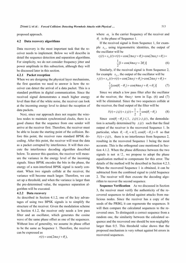
4.2 Data recovery algorithms
Data recovery is the most important task that the re-ceiver needs to implement. Below we will describe in detail the sequence detection and separation algorithms. For simplicity, we do not consider frequency jitter and power amplitude in this subsection, although they will be discussed later in this section. 4.2.1 Packet reception When we are designing the physical layer mechanisms, the first question we need to answer is how the re-ceiver can detect the arrival of a data packet. This is a standard problem in digital communication. Since the received signal demonstrates a much higher energy level than that of the white noise, the receiver can look at the incoming energy level to detect the reception of data packets.
Next, since our approach does not require the wire-less nodes to maintain synchronized clocks, there is a good chance that the sequence from one sender will arrive at the receiver first. Therefore, the receiver must be able to locate the starting point of the collision. Be-fore this point, the receiver runs standard BPSK de-coding. After this point, the receiver will treat the data as a packet corrupted by interference. It will then exe-cute the interference decoding algorithm described below. To answer this question, the receiver will meas-ure the variance in the energy level of the incoming signals. Since BPSK encodes the bits in the phase, the energy of a non-interfered BPSK signal is nearly con-stant. When two signals collide at the receiver, the variance will become much larger. Therefore, we can set up a threshold, and when the variance is larger than the pre-determined value, the sequence separation al-gorithm will be executed. 4.2.2 Data recovery As described in Section 4.1.2, one of the key advan-tages of using two BPSK signals is to simplify the structure of the receiver. Given the modulation scheme in Section 4.1.2, the receiver only needs a low pass filter and an oscillator, which generates the cosine wave of the same phase offset as one of the sequences. Without loss of generality, we assume its phase offset to be the same as Sequence 1. Therefore, the receiver can be expressed as
c 1( ) cos(2π ),r t tω θ= +
where cω is the carrier frequency of the receiver and 1θ is the phase of Sequence 1. If the received signal is from Sequence 1, for exam-
ple 11s , using trigonometric identities, the output of the oscillator will be
1 11 c 1 c 1( ) ( ) ( ) cos(2π ) cos(2π )r t s t r t t tω θ ω θ= = + + =∙ ∙
c 11 [1 cos(4π 2 )]2
tω θ+ + (6)
Similarly, if the received signal is from Sequence 2, for example 21s , the output of the oscillator will be
2 21 c 2 c 1( ) ( ) ( ) cos(2π ) cos(2π )r t s t r t t tω θ ω θ= = + + =∙ ∙
1 2 c 1 21 [cos( ) cos(4π )]2
tθ θ ω θ θ− + + + (7)
Since we attach a low pass filter after the oscillator at the receiver, the c4π tω term in Eqs. (6) and (7) will be eliminated. Since the two sequences collide at the receiver, the final output of the filter will be
1 2 1 21 1( ) ( ) ( ) cos( )2 2
r t t tr r θ θ= + = + − (8)
Since 1 2cos( ) 1θ θ− , 1 2( ) ( )t tr r , the demodula-tion is actually determined by 1( )tr such that the final output of the receiver is the recovered Sequence 1. In particular, when 1 2 π/2,θ θ− = 1 2cos( ) 0θ θ− = so that
1( ) ( ) ,r t tr= there is no interference from Sequence 2, resulting in the recovered Sequence 1 being the most accurate. This is the orthogonal case mentioned in Sec-tion 4.1.2. When the phase difference between the two signals is not π 2/ , we propose to adopt the phase equalization method to compensate for this error. The details of the method will be described in Section 4.2.3. When the recovered Sequence 1 is obtained, it can be subtracted from the combined signal to yield Sequence 2. The receiver will then execute the decoding algo-rithm to recover the second sequence.
Sequence Verification As we discussed in Section 3, the receiver must verify the authenticity of the re-covered sequences to defend against attacks from ma-licious nodes. Since the receiver has a copy of the seeds of the PRBG, it can regenerate the sequences. It will then compare the calculated sequences to the re-covered ones. To distinguish a correct sequence from a random one, the similarity between the calculated se-quence and the recovered one should be non-negligibly larger than 0.5. This threshold value shows that the proposed mechanism is very robust against bit errors in recovered sequences.
Tsinghua Science and Technology, October 2011, 16(5): 505-519
514
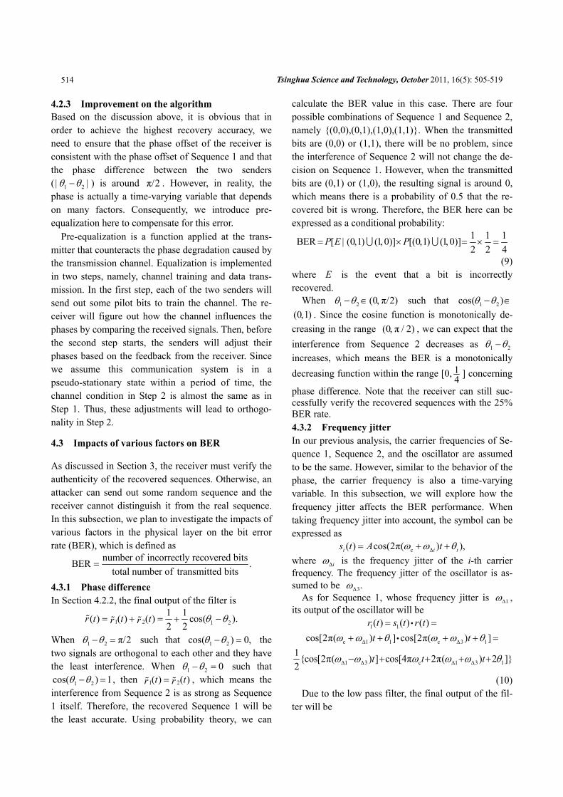
4.2.3 Improvement on the algorithm Based on the discussion above, it is obvious that in order to achieve the highest recovery accuracy, we need to ensure that the phase offset of the receiver is consistent with the phase offset of Sequence 1 and that the phase difference between the two senders ( 1 2θ θ| − | ) is around π/2 . However, in reality, the phase is actually a time-varying variable that depends on many factors. Consequently, we introduce pre- equalization here to compensate for this error.
Pre-equalization is a function applied at the trans-mitter that counteracts the phase degradation caused by the transmission channel. Equalization is implemented in two steps, namely, channel training and data trans-mission. In the first step, each of the two senders will send out some pilot bits to train the channel. The re-ceiver will figure out how the channel influences the phases by comparing the received signals. Then, before the second step starts, the senders will adjust their phases based on the feedback from the receiver. Since we assume this communication system is in a pseudo-stationary state within a period of time, the channel condition in Step 2 is almost the same as in Step 1. Thus, these adjustments will lead to orthogo-nality in Step 2.
4.3 Impacts of various factors on BER
As discussed in Section 3, the receiver must verify the authenticity of the recovered sequences. Otherwise, an attacker can send out some random sequence and the receiver cannot distinguish it from the real sequence. In this subsection, we plan to investigate the impacts of various factors in the physical layer on the bit error rate (BER), which is defined as
number of incorrectly recovered bitsBER .total number of transmitted bits
=
4.3.1 Phase difference In Section 4.2.2, the final output of the filter is
1 2 1 21 1( ) ( ) ( ) cos( ).2 2
r t t tr r θ θ= + = + −
When 1 2 π/2θ θ− = such that 1 2cos( ) 0,θ θ− = the two signals are orthogonal to each other and they have the least interference. When 1 2 0θ θ− = such that
1 2cos( ) 1θ θ− = , then 1 2( ) ( )t tr r= , which means the interference from Sequence 2 is as strong as Sequence 1 itself. Therefore, the recovered Sequence 1 will be the least accurate. Using probability theory, we can
calculate the BER value in this case. There are four possible combinations of Sequence 1 and Sequence 2, namely {(0,0),(0,1),(1,0),(1,1)}. When the transmitted bits are (0,0) or (1,1), there will be no problem, since the interference of Sequence 2 will not change the de-cision on Sequence 1. However, when the transmitted bits are (0,1) or (1,0), the resulting signal is around 0, which means there is a probability of 0.5 that the re-covered bit is wrong. Therefore, the BER here can be expressed as a conditional probability:
BER [ (0 1) (1 0)] [(0 1) (1 0)]P E P= | , , × , ,∪ ∪ 1 1 12 2 4
= × =
(9) where E is the event that a bit is incorrectly recovered.
When 1 2 (0 π/2)θ θ− ∈ , such that 1 2cos( )θ θ− ∈ (0 1), . Since the cosine function is monotonically de-creasing in the range (0 π 2), / , we can expect that the interference from Sequence 2 decreases as 1 2θ θ− increases, which means the BER is a monotonically decreasing function within the range [0, 1
4 ] concerning
phase difference. Note that the receiver can still suc-cessfully verify the recovered sequences with the 25% BER rate. 4.3.2 Frequency jitter In our previous analysis, the carrier frequencies of Se-quence 1, Sequence 2, and the oscillator are assumed to be the same. However, similar to the behavior of the phase, the carrier frequency is also a time-varying variable. In this subsection, we will explore how the frequency jitter affects the BER performance. When taking frequency jitter into account, the symbol can be expressed as
c( ) cos(2π( ) ),i i is t A tω ω θΔ= + + where iωΔ is the frequency jitter of the i-th carrier frequency. The frequency jitter of the oscillator is as-sumed to be 3ωΔ .
As for Sequence 1, whose frequency jitter is 1ωΔ , its output of the oscillator will be
1 1( ) ( ) ( )r t s t r t= =∙
c 1 1 c 3 1cos[2π( ) ] cos[2π( ) ]t tω ω θ ω ω θΔ Δ+ + + + =∙
1 3 c 1 3 11{cos[2π( ) ] cos[4π 2π( ) 2 ]}2
t t tω ω ω ω ω θΔ Δ Δ Δ− + + + +
(10) Due to the low pass filter, the final output of the fil-
ter will be
Zhiwei Li et al.:Forced Collision: Detecting Wormhole Attacks with Physical … 515
1 1 31( ) cos[2π( ) ]2
t tr ω ωΔ Δ= − (11)
Similarly, as for Sequence 2, whose frequency jitter is 2ωΔ , its output of the low pass filter will be
2 2 3 2 11( ) cos[2π( ) ( )]2
t tr ω ω θ θΔ Δ= − + − (12)
Considering the orthogonal case, where 2 1θ θ− = π/2 , Eq. (12) becomes
2 2 3 2 31 1( ) cos[2π( ) π/2] sin[2π( ) ]2 2
t t tr ω ω ω ωΔ Δ Δ Δ= − + = −
(13) In order to get an accurate recovery of Sequence 1,
the 1( )tr should be as large as possible, while 2( )tr should be as small as possible. Therefore, we would like 1 3 0ω ωΔ Δ− = and 2 3 0.ω ωΔ Δ− = In other words, if the carriers have the same frequency jitter, it will have no effect on BER. Otherwise, it will result in an increased number of bit errors.
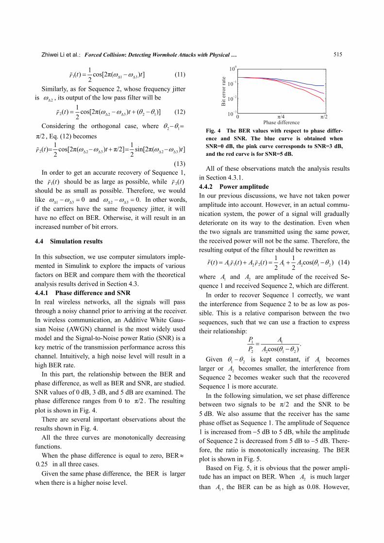
4.4 Simulation results
In this subsection, we use computer simulators imple-mented in Simulink to explore the impacts of various factors on BER and compare them with the theoretical analysis results derived in Section 4.3. 4.4.1 Phase difference and SNR In real wireless networks, all the signals will pass through a noisy channel prior to arriving at the receiver. In wireless communication, an Additive White Gaus-sian Noise (AWGN) channel is the most widely used model and the Signal-to-Noise power Ratio (SNR) is a key metric of the transmission performance across this channel. Intuitively, a high noise level will result in a high BER rate.
In this part, the relationship between the BER and phase difference, as well as BER and SNR, are studied. SNR values of 0 dB, 3 dB, and 5 dB are examined. The phase difference ranges from 0 to π/2 . The resulting plot is shown in Fig. 4.
There are several important observations about the results shown in Fig. 4.
All the three curves are monotonically decreasing functions.
When the phase difference is equal to zero, BER≈ 0 25. in all three cases.
Given the same phase difference, the BER is larger when there is a higher noise level.
Fig. 4 The BER values with respect to phase differ-ence and SNR. The blue curve is obtained when SNR=0 dB, the pink curve corresponds to SNR=3 dB, and the red curve is for SNR=5 dB.
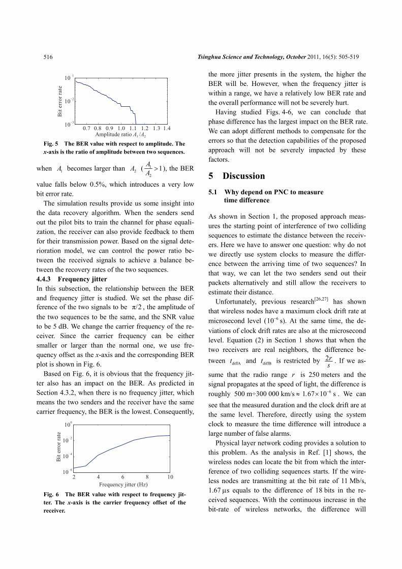
All of these observations match the analysis results in Section 4.3.1. 4.4.2 Power amplitude In our previous discussions, we have not taken power amplitude into account. However, in an actual commu-nication system, the power of a signal will gradually deteriorate on its way to the destination. Even when the two signals are transmitted using the same power, the received power will not be the same. Therefore, the resulting output of the filter should be rewritten as
1 21 2 1 2 1 21 1( ) ( ) ( ) cos( )2 2
r t A t A t A Ar r θ θ= + = + − (14)
where 1A and 2A are amplitude of the received Se-quence 1 and received Sequence 2, which are different.
In order to recover Sequence 1 correctly, we want the interference from Sequence 2 to be as low as pos-sible. This is a relative comparison between the two sequences, such that we can use a fraction to express their relationship:
1 1
2 2 1 2
.cos( )
P AP A θ θ
=−
Given 1 2θ θ− is kept constant, if 1A becomes larger or 2A becomes smaller, the interference from Sequence 2 becomes weaker such that the recovered Sequence 1 is more accurate.
In the following simulation, we set phase difference between two signals to be π/2 and the SNR to be 5 dB. We also assume that the receiver has the same phase offset as Sequence 1. The amplitude of Sequence 1 is increased from −5 dB to 5 dB, while the amplitude of Sequence 2 is decreased from 5 dB to −5 dB. There-fore, the ratio is monotonically increasing. The BER plot is shown in Fig. 5.
Based on Fig. 5, it is obvious that the power ampli-tude has an impact on BER. When 2A is much larger than 1A , the BER can be as high as 0.08. However,
Tsinghua Science and Technology, October 2011, 16(5): 505-519
516
when 1A becomes larger than 2A ( 1
21A
A > ), the BER
value falls below 0.5%, which introduces a very low bit error rate.
The simulation results provide us some insight into the data recovery algorithm. When the senders send out the pilot bits to train the channel for phase equali-zation, the receiver can also provide feedback to them for their transmission power. Based on the signal dete-rioration model, we can control the power ratio be-tween the received signals to achieve a balance be-tween the recovery rates of the two sequences. 4.4.3 Frequency jitter In this subsection, the relationship between the BER and frequency jitter is studied. We set the phase dif-ference of the two signals to be π/2 , the amplitude of the two sequences to be the same, and the SNR value to be 5 dB. We change the carrier frequency of the re-ceiver. Since the carrier frequency can be either smaller or larger than the normal one, we use fre-quency offset as the x-axis and the corresponding BER plot is shown in Fig. 6.
Based on Fig. 6, it is obvious that the frequency jit-ter also has an impact on the BER. As predicted in Section 4.3.2, when there is no frequency jitter, which means the two senders and the receiver have the same carrier frequency, the BER is the lowest. Consequently,
the more jitter presents in the system, the higher the BER will be. However, when the frequency jitter is within a range, we have a relatively low BER rate and the overall performance will not be severely hurt.
Having studied Figs. 4-6, we can conclude that phase difference has the largest impact on the BER rate. We can adopt different methods to compensate for the errors so that the detection capabilities of the proposed approach will not be severely impacted by these factors.
5 Discussion
5.1 Why depend on PNC to measure time difference
As shown in Section 1, the proposed approach meas-ures the starting point of interference of two colliding sequences to estimate the distance between the receiv-ers. Here we have to answer one question: why do not we directly use system clocks to measure the differ-ence between the arriving time of two sequences? In that way, we can let the two senders send out their packets alternatively and still allow the receivers to estimate their distance.
Unfortunately, previous research[26,27] has shown that wireless nodes have a maximum clock drift rate at microsecond level ( 610− s). At the same time, the de-viations of clock drift rates are also at the microsecond level. Equation (2) in Section 1 shows that when the two receivers are real neighbors, the difference be-tween diffAt and diffBt is restricted by 2r
s . If we as-
sume that the radio range r is 250 meters and the signal propagates at the speed of light, the difference is roughly 500 m÷300 000 km/s ≈ 61 67 10 s−. × . We can see that the measured duration and the clock drift are at the same level. Therefore, directly using the system clock to measure the time difference will introduce a large number of false alarms.
Physical layer network coding provides a solution to this problem. As the analysis in Ref. [1] shows, the wireless nodes can locate the bit from which the inter-ference of two colliding sequences starts. If the wire-less nodes are transmitting at the bit rate of 11 Mb/s, 1.67 μs equals to the difference of 18 bits in the re-ceived sequences. With the continuous increase in the bit-rate of wireless networks, the difference will
Fig. 5 The BER value with respect to amplitude. The x-axis is the ratio of amplitude between two sequences.
Fig. 6 The BER value with respect to frequency jit-ter. The x-axis is the carrier frequency offset of the receiver.
Zhiwei Li et al.:Forced Collision: Detecting Wormhole Attacks with Physical … 517
become larger and larger. Therefore, physical layer network coding allows us to more accurately measure the difference and detect fake neighbor connections.
5.2 Security of the proposed approach
In Section 3 we discuss the authenticity of the received sequences and the prevention of man-in-the-middle attack. In this part, we study other security aspects of the approach.
When node A uses ( xorC Dr r ) as the seed to gener-ate the pilot bits, it is very difficult for the attackers to counterfeit this information. If we assume that the seeds Cr and Dr have the length of k and the pilot bits have the length of h , the probability that an at-tacker can correctly regenerate the pilot bits without the information of Cr and Dr equals to
1 1max( , )2 2h k . We can adjust the values of k and h
to prevent the attackers from fabricating the starting signal and conducting man-in-the-middle attack on the mechanism.
Since the attackers have a total control over the tun-neling procedure, they can block the verification pro-cedure by discarding the packets going through the wormhole. This operation, however, will allow the le-gitimate nodes to derive more information about the wormholes. If node A fails to get a sequence from a sender and it is not because of the low quality of the communication channel, we conclude that there is a wormhole between A and the sender. This can be proven by contradiction. If there is no wormhole be-tween A and the sender, we know that the distance between them is shorter than 2 .r Therefore, the sender will send out the sequence when it receives the pilot bits and A would have received the sequence. When node B fails to receive a sequence, it will ex-change information with node .A If A gets that se-quence, B concludes that there is a wormhole be-tween the sender and .B It can draw this conclusion since node A confirms that the sender actually sends out the sequence. Therefore, if there is no wormhole between B and the sender, it would have received it. Based on the analysis, we can see that the attackers will expose more wormholes when they try to avoid detection by discarding packets.
Except for discarding packets, the attackers can also intentionally add noise to the packets when they tunnel
them through the wormhole. This operation may lead to one of the two results. If the introduced noises are not strong and the receivers can still verify the authen-ticity of the sequences, the neighbor verification pro-cedure will not be impacted. On the contrary, if the bit error rate becomes very large and the receiver can no longer verify the authenticity of the sequence, it will treat the packet as a lost one. The receiver can then follow the description in the previous paragraph and treat the connection as a wormhole. This decision can be justified as follows: treating a very error-prone connection as a wormhole and avoiding it during the routing procedure will not significantly deteriorate the network performance.
5.3 False alarms of the proposed approach
False positive and false negative alarms are important parameters to evaluate a detection mechanism. In Sec-tion 3.2, we propose to adopt multiple rounds of veri-fication to reduce false negative alarms. In this part, we focus on the investigation of false positive alarms.
When nodes A and B are real neighbors and the proposed approach identifies that they are connected through a wormhole, we have a false positive alarm. If both of the senders C and D are real neighbors to at least one of the receivers, we can derive that the two senders are within 2r to the two receivers. In this way, both the pilot bits and the transmitted sequences will reach their targets and the verification procedure will complete successfully. Therefore, to cause a false positive alarm, we must have at least one sender con-necting to both receivers through wormholes. Without losing generality, we assume that the sender is node C.
If the two receivers A and B get the sequence from C through the same sending operation of the wormhole, the attackers will not be able to manipulate the difference between diffAt and diffBt since this op-eration has the same effect as node C is at the posi-tion of the wormhole node. The attacker can keep the sequence in the wormhole for a period of time. This operation, however, has the same effect as node C adjusts its transmission time. Previous analysis has shown that this parameter will be removed from the final calculation result.
With this analysis, we find that the attackers need to deliver the sequence from C to the two receivers through two different sending operations so that they
Tsinghua Science and Technology, October 2011, 16(5): 505-519
518
can control the difference between their arriving time. This goal can be achieved through maintaining two separate wormholes to the receivers, or transmitting the sequences through different directional antennas. Both schemes will increase the deployment difficulty and the hardware costs of the attackers. At the same time, the following simulation will show that the false positive alarms have limited impacts on the average path length in the network.
In this simulation, we assume that the legitimate nodes are deployed randomly and uniformly in a 2 km 2 km× area. The transmission range r is 250 m. Two legitimate nodes A and B are real neighbors. When they want to verify the neighbor rela-tionship, the attackers will transmit the sequences to them through two malicious nodes X and X ′ re-spectively. Here X is only a neighbor of A and X ′ is only a neighbor of B . Since A and B are real neighbors, the physical distance between X and X ′ is in the interval [0,3 ]r . Under these assumptions,
we study the relationship among the number of false positive alarms, the node density, and the number of wormholes in the network.
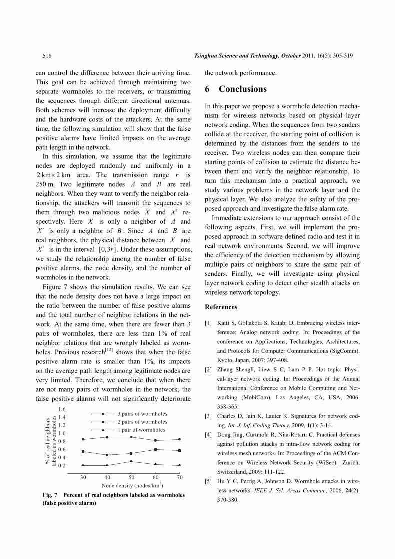
Figure 7 shows the simulation results. We can see that the node density does not have a large impact on the ratio between the number of false positive alarms and the total number of neighbor relations in the net-work. At the same time, when there are fewer than 3 pairs of wormholes, there are less than 1% of real neighbor relations that are wrongly labeled as worm-holes. Previous research[12] shows that when the false positive alarm rate is smaller than 1%, its impacts on the average path length among legitimate nodes are very limited. Therefore, we conclude that when there are not many pairs of wormholes in the network, the false positive alarms will not significantly deteriorate
the network performance.
6 Conclusions
In this paper we propose a wormhole detection mecha-nism for wireless networks based on physical layer network coding. When the sequences from two senders collide at the receiver, the starting point of collision is determined by the distances from the senders to the receiver. Two wireless nodes can then compare their starting points of collision to estimate the distance be-tween them and verify the neighbor relationship. To turn this mechanism into a practical approach, we study various problems in the network layer and the physical layer. We also analyze the safety of the pro-posed approach and investigate the false alarm rate.
Immediate extensions to our approach consist of the following aspects. First, we will implement the pro-posed approach in software defined radio and test it in real network environments. Second, we will improve the efficiency of the detection mechanism by allowing multiple pairs of neighbors to share the same pair of senders. Finally, we will investigate using physical layer network coding to detect other stealth attacks on wireless network topology.
References
[1] Katti S, Gollakota S, Katabi D. Embracing wireless inter-ference: Analog network coding. In: Proceedings of the conference on Applications, Technologies, Architectures, and Protocols for Computer Communications (SigComm). Kyoto, Japan, 2007: 397-408.
[2] Zhang Shengli, Liew S C, Lam P P. Hot topic: Physi-cal-layer network coding. In: Proceedings of the Annual International Conference on Mobile Computing and Net-working (MobiCom). Los Angeles, CA, USA, 2006: 358-365.
[3] Charles D, Jain K, Lauter K. Signatures for network cod-ing. Int. J. Inf. Coding Theory, 2009, 1(1): 3-14.
[4] Dong Jing, Curtmola R, Nita-Rotaru C. Practical defenses against pollution attacks in intra-flow network coding for wireless mesh networks. In: Proceedings of the ACM Con-ference on Wireless Network Security (WiSec). Zurich, Switzerland, 2009: 111-122.
[5] Hu Y C, Perrig A, Johnson D. Wormhole attacks in wire-less networks. IEEE J. Sel. Areas Commun., 2006, 24(2): 370-380.
Fig. 7 Percent of real neighbors labeled as wormholes (false positive alarm)
Zhiwei Li et al.:Forced Collision: Detecting Wormhole Attacks with Physical … 519
[6] apkumC S, Buttyán L, Hubaux J P. Sector: Secure tracking of node encounters in multi-hop wireless networks. In: Proceedings of ACM Workshop on Security of Ad Hoc and Sensor Networks. Alexandria, VA, USA, 2003: 21-32.
[7] Hu Lingxuan, Evans D. Using directional antennas to pre-vent wormhole attacks. In: Proceedings of Network and Distributed System Security Symposium. San Diego, USA, 2004.
[8] Khalil I, Bagchi S, Shroff N B. Liteworp: Detection and isolation of the wormhole attack in static multihop wireless networks. Comput. Netw., 2007, 51(13): 3750-3772.
[9] Khalil I, Bagchi S, Shroff N B. Mobiworp: Mitigation of the wormhole attack in mobile multihop wireless networks. Ad Hoc Netw., 2008, 6(3): 344-362.
[10] Wang Xia, Wong J. An end-to-end detection of wormhole attack in wireless ad-hoc networks. In: Annual Interna-tional Computer Software and Applications Conference. Beijing, China, 2007: 39-48.
[11] Eriksson J, Krishnamurthy S, Faloutsos M. Truelink: A practical countermeasure to the wormhole attack in wire-less networks. In: Proceedings of IEEE International Con-ference on Network Protocols. Santa Barbara, CA, USA, 2006: 75-84.
[12] Wang Weichao, Bhargava B. Visualization of wormholes in sensor networks. In: Proceedings of the 3rd ACM Work-shop on Wireless Security (WiSe). Philadelphia, PA, USA, 2004: 51-60.
[13] Wang Weichao, Kong Jiejun, Bhargava B, et al. Visualisa-tion of wormholes in underwater sensor networks: A dis-tributed approach. Int. J. Secur. Netw., 2008, 3(1): 10-23.
[14] Poovendran R, Lazos L. A graph theoretic framework for preventing the wormhole attack in wireless ad hoc net-works. Wirel. Netw., 2007, 13(1): 27-59.
[15] Maheshwari R, Gao Jie, Das S R. Detecting wormhole attacks in wireless networks using connectivity informa-tion. In: 26th IEEE International Conference on Computer Communications. Anchorage, AK, USA, 2007: 107-115.
[16] Qian Lijun, Song Nan, Li Xiangfang. Detection of worm-hole attacks in multi-path routed wireless ad hoc networks: A statistical analysis approach. Journal of Network and Computer Applications, 2007, 30(1): 308-330.
[17] Buttyan L, Dora L, Vajda I. Statistical wormhole detection in sensor networks. In: European Workshop on Security and Privacy in Ad-hoc and Sensor Networks. Visegrad, Hungary, 2005: 128-141.
[18] Stankovic V, Fagoonee L, Moinian A, et al. Wireless full-duplex communications based on network coding. In: Proceedings of 45th Annual Allerton Conference on Com-munications, Control and Computing. Illinois, USA, 2007: 690-694.
[19] Zhang Shengli, Liew S C, Lu Lu. Physical layer network coding schemes over finite and infinite fields. In: IEEE GLOBECOM. New Orleans, LO, USA, 2008: 1-6.
[20] Pu Wei, Luo Chong, Jiao Binxing, et al. Natural network coding in multi-hop wireless networks. In: IEEE ICC. Bei-jing, China, 2008: 2388-2392.
[21] Hao Yonggang, Goeckel D, Ding Zhiguo, et al. Achievable rates for network coding on the exchange channel. In: IEEE Milcom. Orlando, FL, USA, 2007: 1-7.
[22] Cui Tao, Ho T, Kliewer J. Some results on relay strategies for memoryless two-way relay channels. In: Information Theory and Applications Workshop. San Diego, CA, USA, 2008: 158-164.
[23] Latif R, Hussain M. Hardware-based random number gen-eration in wireless sensor networks (WSNs). In: Proceed-ings of the International Conference and Workshops on Advances in Information Security and Assurance. Seoul, Korea, 2009: 732-740.
[24] Nguyen H, Shinoda Y. A node’s number of neighbors in wireless mobile ad hoc networks: A statistical view. In: Proceedings of International Conference on Networks. Cancun, Mexico, 2009: 52-60.
[25] Tseng C C, Chen H T, Chen K C. Distribution of the node degree for wireless ad hoc networks in shadow fading en-vironments. IEICE Transactions on Communications, 2007, E90-B(8): 2155-2158.
[26] Romer K. Time synchronization in ad hoc networks. In: ACM MOBIHOC. Rome, Italy, 2001: 173-182.
[27] Song Hui, Zhu Sencun, Cao Guohong. Attack-resilient time synchronization for wireless sensor networks. In: Proc. of IEEE International Conference on Mobile Ad-hoc and Sensor Systems (MASS). Washington DC, USA, 2005.