Embed Size (px)
Citation preview
IntroductionThis manual provides information needed to operateand understand the vehicle and its components.More detailed information is contained in the Owner’sWarranty Information for North America booklet, andin the vehicle’s workshop and maintenance manuals.
Custom-built Freightliner vehicles are equipped withvarious chassis and cab components. Not all of theinformation contained in this manual applies to everyvehicle. For details about components in your ve-hicle, refer to the chassis specification pages in-cluded in all new vehicles and to the vehicle specifi-cation decal, located inside the vehicle.
For your reference, keep this manual in the vehicleat all times.
IMPORTANT: Descriptions and specifications inthis manual were in effect at the time of printing.Freightliner Trucks reserves the right to discon-tinue models and to change specifications ordesign at any time without notice and withoutincurring obligation. Descriptions and specifica-tions contained in this publication provide nowarranty, expressed or implied, and are subjectto revisions and editions without notice.
Environmental Concerns andRecommendationsWhenever you see instructions in this manual to dis-card materials, you should first attempt to reclaimand recycle them. To preserve our environment, fol-low appropriate environmental rules and regulationswhen disposing of materials.
Event Data RecorderThis vehicle is equipped with one or more devicesthat record specific vehicle data. The type andamount of data recorded varies depending on howthe vehicle is equipped (such as the brand of engine,if an air bag is installed, or if the vehicle features acollision avoidance system, etc.).
Customer Assistance CenterHaving trouble finding service? Call the CustomerAssistance Center at 1-800-385-4357 or 1-800-FTL-HELP. Call night or day, weekdays or weekends, for
dealer referral, vehicle information, breakdown coor-dination, or Fleetpack assistance. Our people areknowledgeable, professional, and committed to fol-lowing through to help you keep your truck moving.
Reporting Safety DefectsIf you believe that your vehicle has a defect whichcould cause a crash or could cause injury ordeath, you should immediately inform the NationalHighway Traffic Safety Administration (NHTSA) inaddition to notifying Daimler Trucks North AmericaLLC.
If the NHTSA receives similar complaints, it mayopen an investigation, and if it finds that a safetydefect exists in a group of vehicles, it may order arecall and remedy campaign. However, NHTSAcannot become involved in individual problemsbetween you, your dealer, or Daimler Trucks NorthAmerica LLC.
To contact NHTSA, you may call the VehicleSafety Hotline toll-free at 1-888-327-4236 (TTY:1-800-424-9153); go to www.safercar.gov ; orwrite to: Administrator, NHTSA, 1200 New JerseyAvenue, SE, Washington, DC 20590. You can alsoobtain other information about motor vehicle safetyfrom www.safercar.gov .
Canadian customers who wish to report a safety-related defect to Transport Canada, Defect Investi-gations and Recalls, may telephone the toll-freehotline 1-800-333-0510, or contact TransportCanada by mail at: Transport Canada, ASFAD,Place de Ville Tower C, 330 Sparks Street, Ot-tawa, Ontario, Canada K1A 0N5.
For additional road safety information, please visitthe Road Safety website at: www.tc.gc.ca/roadsafety .
Foreword
STI-478-4 (1/11)Part Number STI 478
Printed in U.S.A.

© 2007–2011 Daimler Trucks North America LLC. All rights reserved. Daimler Trucks North America LLC is a Daimlercompany.
No part of this publication, in whole or part, may be translated, reproduced, stored in a retrieval system, or transmittedin any form by any means, electronic, mechanical, photocopying, recording, or otherwise, without the prior written per-mission of Daimler Trucks North America LLC. For additional information, please contact Daimler Trucks NorthAmerica LLC, Service Systems and Documentation, P.O. Box 3849, Portland OR 97208–3849 U.S.A. or refer towww.Daimler-TrucksNorthAmerica.com and www.FreightlinerTrucks.com .
Foreword
ContentsChapter Page
Introduction, Environmental Concerns and Recommendations,Event Data Recorder, Customer Assistance Center, ReportingSafety Defects . . . . . . . . . . . . . . . . . . . . . . . . . . . . . . . . . . . . . . . . . . . . . . . . . . . . . Foreword
1 Vehicle Identification . . . . . . . . . . . . . . . . . . . . . . . . . . . . . . . . . . . . . . . . . . . . . . . . . . . . . . 1.12 Vehicle Access . . . . . . . . . . . . . . . . . . . . . . . . . . . . . . . . . . . . . . . . . . . . . . . . . . . . . . . . . . 2.13 Electrical System . . . . . . . . . . . . . . . . . . . . . . . . . . . . . . . . . . . . . . . . . . . . . . . . . . . . . . . . 3.14 Instruments . . . . . . . . . . . . . . . . . . . . . . . . . . . . . . . . . . . . . . . . . . . . . . . . . . . . . . . . . . . . . 4.15 Driver Controls . . . . . . . . . . . . . . . . . . . . . . . . . . . . . . . . . . . . . . . . . . . . . . . . . . . . . . . . . . 5.16 Seats and Restraints . . . . . . . . . . . . . . . . . . . . . . . . . . . . . . . . . . . . . . . . . . . . . . . . . . . . . 6.17 Climate Control . . . . . . . . . . . . . . . . . . . . . . . . . . . . . . . . . . . . . . . . . . . . . . . . . . . . . . . . . . 7.18 Cab Features . . . . . . . . . . . . . . . . . . . . . . . . . . . . . . . . . . . . . . . . . . . . . . . . . . . . . . . . . . . 8.19 Engine Starting, Operation, and Shutdown . . . . . . . . . . . . . . . . . . . . . . . . . . . . . . . . . . . . 9.1
10 Optional Engine Systems . . . . . . . . . . . . . . . . . . . . . . . . . . . . . . . . . . . . . . . . . . . . . . . . . 10.111 Aftertreatment Systems (ATS) . . . . . . . . . . . . . . . . . . . . . . . . . . . . . . . . . . . . . . . . . . . . . 11.112 Air Brake System . . . . . . . . . . . . . . . . . . . . . . . . . . . . . . . . . . . . . . . . . . . . . . . . . . . . . . . 12.113 Engine Brakes . . . . . . . . . . . . . . . . . . . . . . . . . . . . . . . . . . . . . . . . . . . . . . . . . . . . . . . . . 13.114 Manual Transmissions and Hydraulic Clutch . . . . . . . . . . . . . . . . . . . . . . . . . . . . . . . . . 14.115 Automated Transmissions . . . . . . . . . . . . . . . . . . . . . . . . . . . . . . . . . . . . . . . . . . . . . . . . 15.116 Drive Axles . . . . . . . . . . . . . . . . . . . . . . . . . . . . . . . . . . . . . . . . . . . . . . . . . . . . . . . . . . . . 16.117 Steering System . . . . . . . . . . . . . . . . . . . . . . . . . . . . . . . . . . . . . . . . . . . . . . . . . . . . . . . . 17.118 Fifth Wheels . . . . . . . . . . . . . . . . . . . . . . . . . . . . . . . . . . . . . . . . . . . . . . . . . . . . . . . . . . . 18.119 Trailer Couplings . . . . . . . . . . . . . . . . . . . . . . . . . . . . . . . . . . . . . . . . . . . . . . . . . . . . . . . . 19.120 Pre- and Post-Trip Checklists . . . . . . . . . . . . . . . . . . . . . . . . . . . . . . . . . . . . . . . . . . . . . 20.121 Pre- and Post-Trip Inspections and Maintenance . . . . . . . . . . . . . . . . . . . . . . . . . . . . . . 21.122 Cab Appearance . . . . . . . . . . . . . . . . . . . . . . . . . . . . . . . . . . . . . . . . . . . . . . . . . . . . . . . . 22.123 Headlight Aiming . . . . . . . . . . . . . . . . . . . . . . . . . . . . . . . . . . . . . . . . . . . . . . . . . . . . . . . . 23.124 In an Emergency . . . . . . . . . . . . . . . . . . . . . . . . . . . . . . . . . . . . . . . . . . . . . . . . . . . . . . . 24.125 Specifications . . . . . . . . . . . . . . . . . . . . . . . . . . . . . . . . . . . . . . . . . . . . . . . . . . . . . . . . . . 25.1
Index . . . . . . . . . . . . . . . . . . . . . . . . . . . . . . . . . . . . . . . . . . . . . . . . . . . . . . . . . . . . . . . . . . I.1
1
Vehicle IdentificationVehicle Specification Decal . . . . . . . . . . . . . . . . . . . . . . . . . . . . . . . . . . . . . . . . . . . . . . . . . . . . . . . . . 1.1Federal Motor Vehicle Safety Standard (FMVSS) Labels . . . . . . . . . . . . . . . . . . . . . . . . . . . . . . . . . . 1.1Canadian Motor Vehicle Safety Standard (CMVSS) Labels . . . . . . . . . . . . . . . . . . . . . . . . . . . . . . . . 1.1Tire and Rim Labels . . . . . . . . . . . . . . . . . . . . . . . . . . . . . . . . . . . . . . . . . . . . . . . . . . . . . . . . . . . . . . . 1.2EPA Vehicle Noise Emission Control Label . . . . . . . . . . . . . . . . . . . . . . . . . . . . . . . . . . . . . . . . . . . . . 1.2EPA07 and EPA10 Emission Control . . . . . . . . . . . . . . . . . . . . . . . . . . . . . . . . . . . . . . . . . . . . . . . . . . 1.2
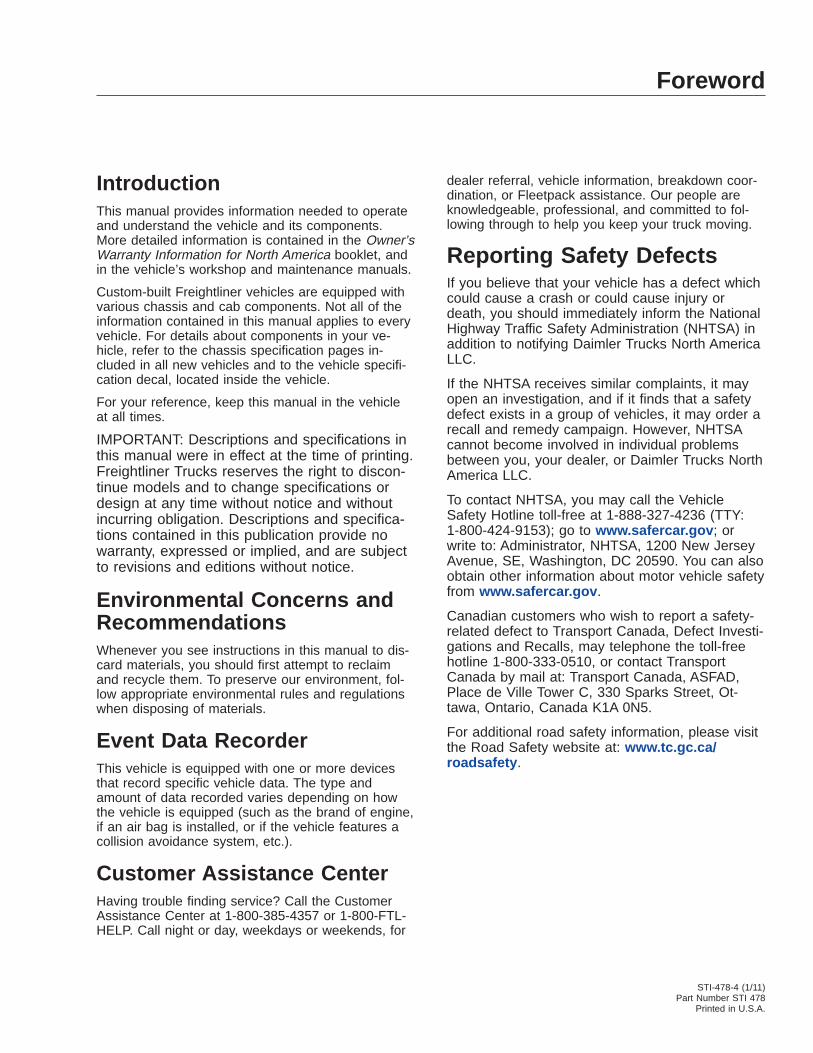
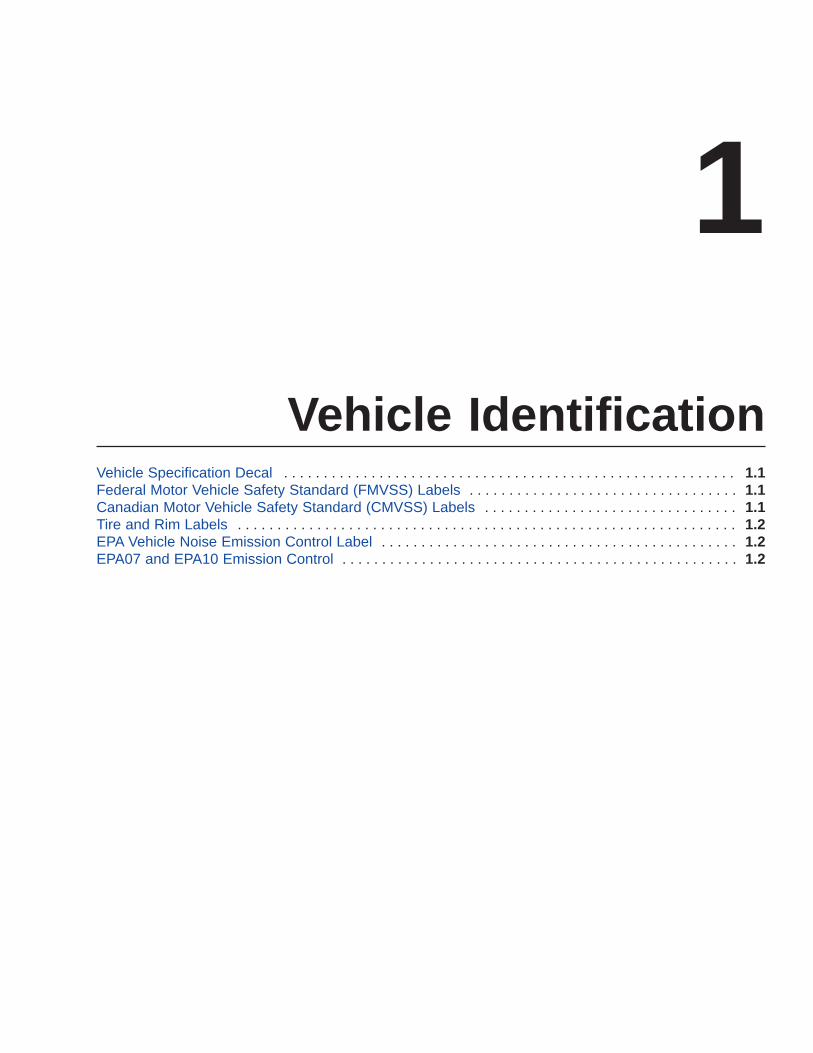
Vehicle Specification DecalThe vehicle specification decal lists the vehiclemodel, identification number, and major componentmodels. It also lists the major assemblies and instal-lations shown on the chassis specification sheet.One copy of the vehicle specification decal is at-tached to the inside of the sliding storage/wastedrawer; another copy is inside the rear cover of theOwner’s Warranty Information for North Americabooklet. An illustration of the decal is shown inFig. 1.1 .
NOTE: Labels shown in this chapter are ex-amples only. Actual specifications may vary fromvehicle to vehicle.
Federal Motor Vehicle SafetyStandard (FMVSS) LabelsNOTE: Due to the variety of FMVSS certificationrequirements, not all of the labels shown willapply to your vehicle.
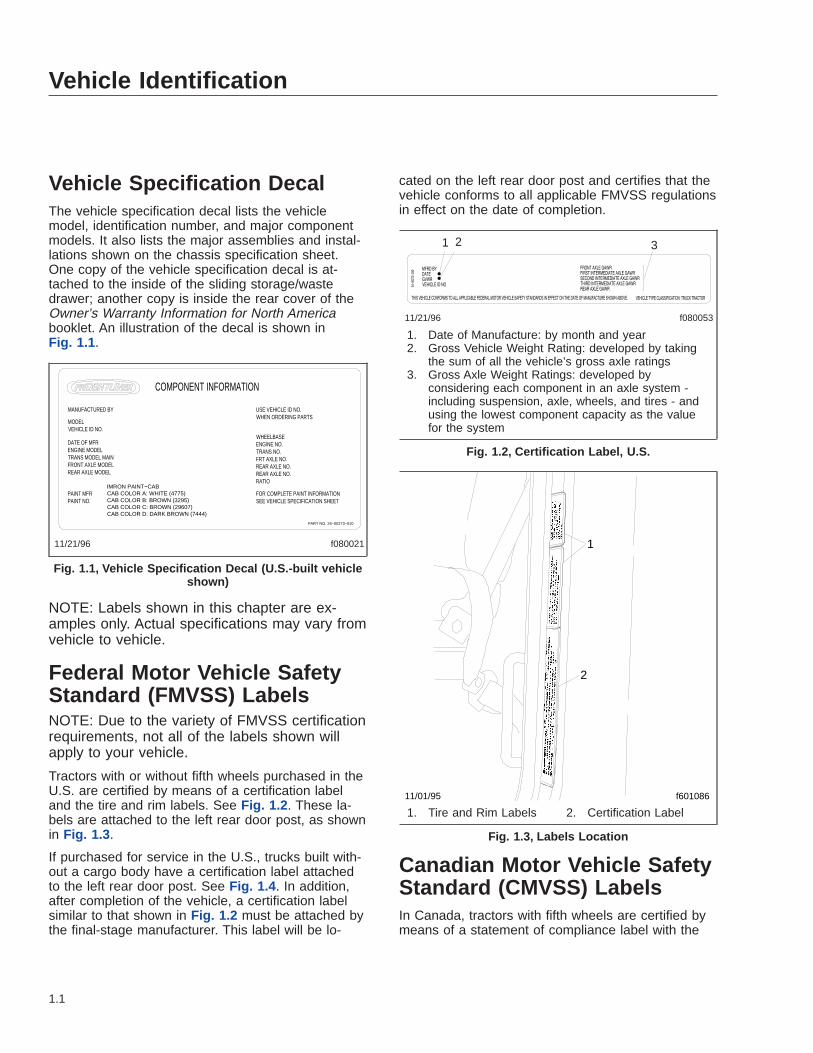
Tractors with or without fifth wheels purchased in theU.S. are certified by means of a certification labeland the tire and rim labels. See Fig. 1.2 . These la-bels are attached to the left rear door post, as shownin Fig. 1.3 .
If purchased for service in the U.S., trucks built with-out a cargo body have a certification label attachedto the left rear door post. See Fig. 1.4 . In addition,after completion of the vehicle, a certification labelsimilar to that shown in Fig. 1.2 must be attached bythe final-stage manufacturer. This label will be lo-
cated on the left rear door post and certifies that thevehicle conforms to all applicable FMVSS regulationsin effect on the date of completion.
Canadian Motor Vehicle SafetyStandard (CMVSS) LabelsIn Canada, tractors with fifth wheels are certified bymeans of a statement of compliance label with the
f08002111/21/96
USE VEHICLE ID NO.WHEN ORDERING PARTS
WHEELBASEENGINE NO.TRANS NO.FRT AXLE NO.REAR AXLE NO.REAR AXLE NO.RATIO
FOR COMPLETE PAINT INFORMATIONSEE VEHICLE SPECIFICATION SHEET
MANUFACTURED BY
MODELVEHICLE ID NO.
DATE OF MFRENGINE MODELTRANS MODEL MAINFRONT AXLE MODELREAR AXLE MODEL
PAINT MFRPAINT NO.
PART NO. 24−00273−010
COMPONENT INFORMATION
IMRON PAINT−CABCAB COLOR A: WHITE (4775)CAB COLOR B: BROWN (3295)CAB COLOR C: BROWN (29607)CAB COLOR D: DARK BROWN (7444)
Fig. 1.1, Vehicle Specification Decal (U.S.-built vehicleshown)
11/21/96 f080053
1 2 3
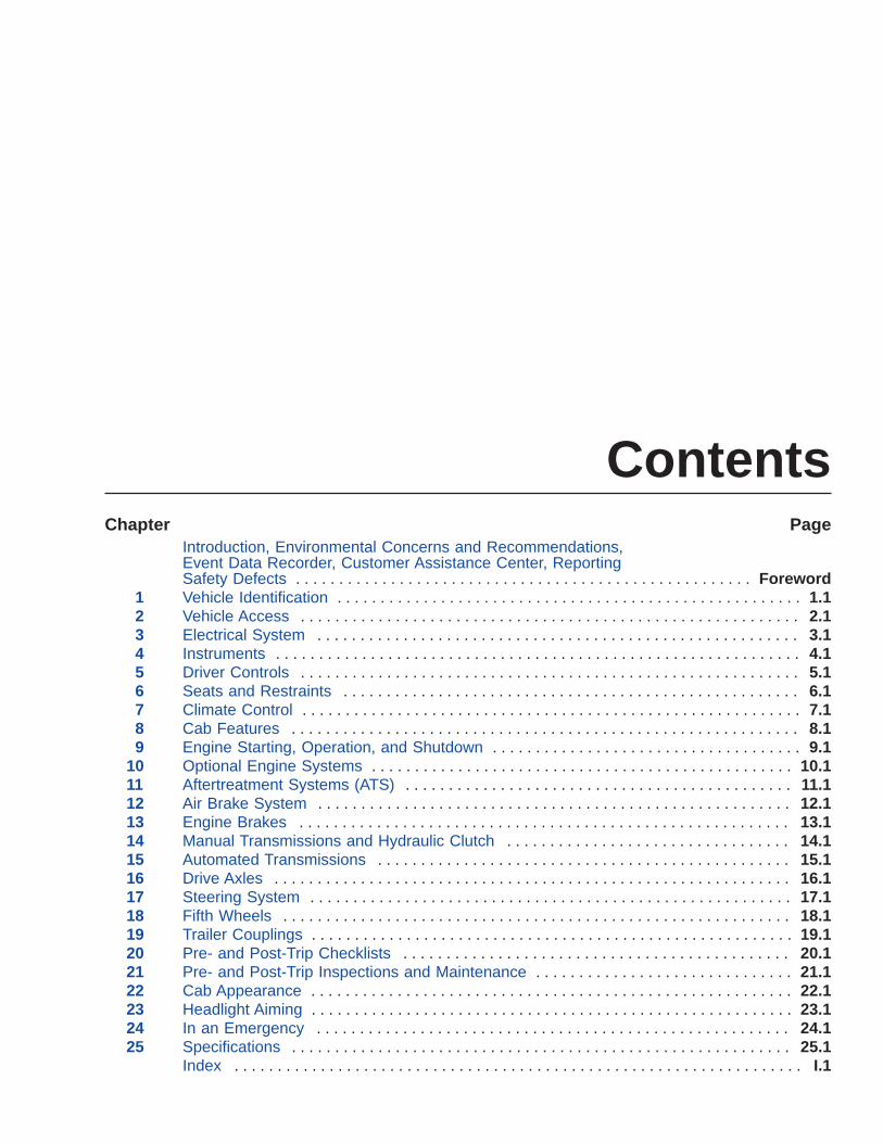
1. Date of Manufacture: by month and year2. Gross Vehicle Weight Rating: developed by taking
the sum of all the vehicle’s gross axle ratings3. Gross Axle Weight Ratings: developed by
considering each component in an axle system -including suspension, axle, wheels, and tires - andusing the lowest component capacity as the valuefor the system
Fig. 1.2, Certification Label, U.S.
1
2
11/01/95 f601086
1. Tire and Rim Labels 2. Certification Label
Fig. 1.3, Labels Location
Vehicle Identification
1.1
Canadian National Safety Mark attached to the leftrear door post. See Fig. 1.5 .
If purchased for service in Canada, trucks built with-out a cargo body and tractors built without a fifthwheel are certified by a "Statement of Compliance"label, similar to Fig. 1.2 . This label must be attachedby the final-stage manufacturer after completion ofthe vehicle. The label is located on the left rear doorpost, and certifies that the vehicle conforms to allapplicable CMVSS regulations in effect on the dateof completion.
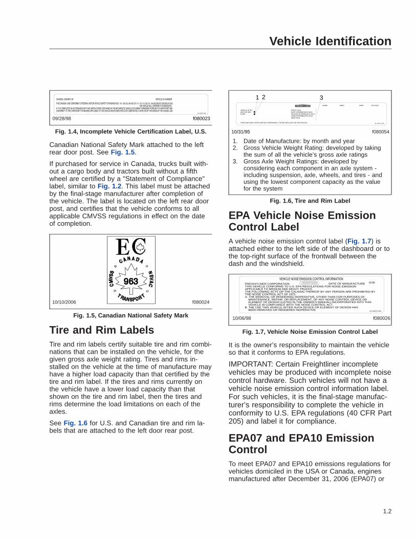
Tire and Rim LabelsTire and rim labels certify suitable tire and rim combi-nations that can be installed on the vehicle, for thegiven gross axle weight rating. Tires and rims in-stalled on the vehicle at the time of manufacture mayhave a higher load capacity than that certified by thetire and rim label. If the tires and rims currently onthe vehicle have a lower load capacity than thatshown on the tire and rim label, then the tires andrims determine the load limitations on each of theaxles.
See Fig. 1.6 for U.S. and Canadian tire and rim la-bels that are attached to the left door rear post.
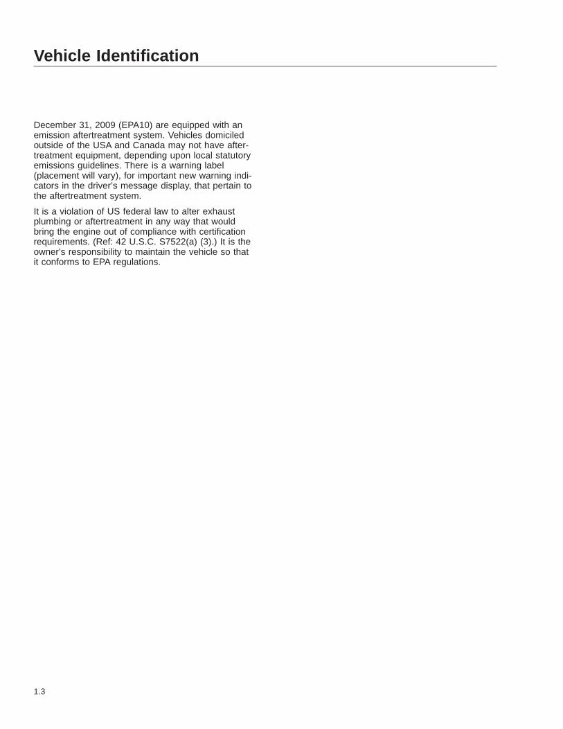
EPA Vehicle Noise EmissionControl LabelA vehicle noise emission control label (Fig. 1.7 ) isattached either to the left side of the dashboard or tothe top-right surface of the frontwall between thedash and the windshield.
It is the owner’s responsibility to maintain the vehicleso that it conforms to EPA regulations.
IMPORTANT: Certain Freightliner incompletevehicles may be produced with incomplete noisecontrol hardware. Such vehicles will not have avehicle noise emission control information label.For such vehicles, it is the final-stage manufac-turer’s responsibility to complete the vehicle inconformity to U.S. EPA regulations (40 CFR Part205) and label it for compliance.
EPA07 and EPA10 EmissionControlTo meet EPA07 and EPA10 emissions regulations forvehicles domiciled in the USA or Canada, enginesmanufactured after December 31, 2006 (EPA07) or
09/28/98 f080023
Fig. 1.4, Incomplete Vehicle Certification Label, U.S.
f08002410/10/2006
Fig. 1.5, Canadian National Safety Mark
f080054
24−00273−040TIRES AND RIMS LISTED ARE NOT NECESSARILY THOSE INSTALLED ON THE VEHICLE.
VEHICLE ID NO.DATE OF MFRGVWR
FRONT AXLEFIRST INTERMEDIATE AXLESECOND INTERMEDIATE AXLETHIRD INTERMEDIATE AXLEREAR AXLE
GAWR TIRES RIMS PSI COLD
1 2 3
10/31/95
1. Date of Manufacture: by month and year2. Gross Vehicle Weight Rating: developed by taking
the sum of all the vehicle’s gross axle ratings3. Gross Axle Weight Ratings: developed by
considering each component in an axle system -including suspension, axle, wheels, and tires - andusing the lowest component capacity as the valuefor the system
Fig. 1.6, Tire and Rim Label
10/06/98 f080026
24−00273−020
VEHICLE NOISE EMISSION CONTROL INFORMATIONFREIGHTLINER CORPORATIONTHIS VEHICLE CONFORMS TO U.S. EPA REGULATIONS FOR NOISE EMISSIONAPPLICABLE TO MEDIUM AND HEAVY TRUCKS.THE FOLLOWING ACTS OR THE CAUSING THEREOF BY ANY PERSON ARE PROHIBITED BYTHE NOISE CONTROL ACT OF 1972:A. THE REMOVAL OR RENDERING INOPERATIVE, OTHER THAN FOR PURPOSES OF MAINTENANCE, REPAIR, OR REPLACEMENT, OF ANY NOISE CONTROL DEVICE OR ELEMENT OF DESIGN (LISTED IN THE OWNER’S MANUAL) INCORPORATED INTO THIS VEHICLE IN COMPLIANCE WITH THE NOISE CONTROL ACT.B. THE USE THIS VEHICLE AFTER SUCH DEVICE OR ELEMENT OF DESIGN HAS BEEN REMOVED OR RENDERED INOPERATIVE.
DATE OF MANUFACTURE 01/96
Fig. 1.7, Vehicle Noise Emission Control Label
Vehicle Identification
1.2
December 31, 2009 (EPA10) are equipped with anemission aftertreatment system. Vehicles domiciledoutside of the USA and Canada may not have after-treatment equipment, depending upon local statutoryemissions guidelines. There is a warning label(placement will vary), for important new warning indi-cators in the driver’s message display, that pertain tothe aftertreatment system.
It is a violation of US federal law to alter exhaustplumbing or aftertreatment in any way that wouldbring the engine out of compliance with certificationrequirements. (Ref: 42 U.S.C. S7522(a) (3).) It is theowner’s responsibility to maintain the vehicle so thatit conforms to EPA regulations.
Vehicle Identification
1.3
2
Vehicle AccessCab Door Locks and Handles . . . . . . . . . . . . . . . . . . . . . . . . . . . . . . . . . . . . . . . . . . . . . . . . . . . . . . . 2.1Grab Handles and Access Steps . . . . . . . . . . . . . . . . . . . . . . . . . . . . . . . . . . . . . . . . . . . . . . . . . . . . . 2.1Cab-to-Sleeper Access . . . . . . . . . . . . . . . . . . . . . . . . . . . . . . . . . . . . . . . . . . . . . . . . . . . . . . . . . . . . . 2.3Sleeper Door . . . . . . . . . . . . . . . . . . . . . . . . . . . . . . . . . . . . . . . . . . . . . . . . . . . . . . . . . . . . . . . . . . . . . 2.3Sleeper Luggage Door . . . . . . . . . . . . . . . . . . . . . . . . . . . . . . . . . . . . . . . . . . . . . . . . . . . . . . . . . . . . . 2.4Back-of-Cab Access . . . . . . . . . . . . . . . . . . . . . . . . . . . . . . . . . . . . . . . . . . . . . . . . . . . . . . . . . . . . . . . 2.4Hood Opening and Closing . . . . . . . . . . . . . . . . . . . . . . . . . . . . . . . . . . . . . . . . . . . . . . . . . . . . . . . . . 2.5
Cab Door Locks and HandlesOne common key operates the ignition switch and allof the door locks.
IMPORTANT: Each key is numbered. Recordthe number so a duplicate key can be made, ifneeded.
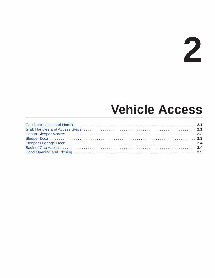
To unlock the driver’s door from outside the cab, in-sert the key in the lockset and turn it one-quarter turnclockwise. See Fig. 2.1 . To remove the key, turn itcounterclockwise to the original position. Pull out onthe door pull handle to open the door.
To unlock the passenger’s door from outside the cab,insert the key in the lockset and turn it one-quarterturn counterclockwise. Turn the key clockwise to theoriginal position to remove it.
NOTE: The cab door locks can be operatedwhen the doors are open.
To lock a door from outside the cab, insert the key inthe lockset and turn it in the direction opposite to theunlocking direction (counterclockwise for the driver’sdoor, clockwise for the passenger’s door). Close thedoor if it is open.
To lock either door from inside the cab, push the lockbutton downwards. See Fig. 2.2 .
To open the door from the inside, lift up on the doorlever. This will unlatch the door whether or not it islocked.
To unlock the door without unlatching it, pull the lockbutton upwards.
Grab Handles and AccessSteps
WARNINGWet or dirty shoe soles greatly increase thechance of slipping or falling. If your soles are wetor dirty, be especially careful when climbingonto, or down from, the back-of-cab area.
Always maintain three-point contact with theback-of-cab access supports while entering andexiting the back-of-cab area. Three-point contactmeans both feet and one hand, or both handsand one foot, on the grab handles, steps, anddeck plates. Other areas are not meant to sup-port back-of-cab access, and grabbing or step-ping in the wrong place could lead to a fall, andpersonal injury.
Be careful not to get hands or feet tangled inhoses or other back-of-cab equipment. Careless-ness could cause a person to trip and fall, withpossible injury.
10/22/2001 f720397
1
2
3
1. Key2. Lockset
3. Door Pull Handle
Fig. 2.1, Exterior Door Handle
06/22/2006
1
2
3 f720639
1. Lock Button2. Integral Door Upper Grab Handle3. Door Lever
Fig. 2.2, Door Interior
Vehicle Access
2.1
Entering the Driver SideWhen entering the cab from the driver side, use thegrab handle and access steps as follows:
1. Open the driver side door, and place anythingthat you are carrying in the cab.
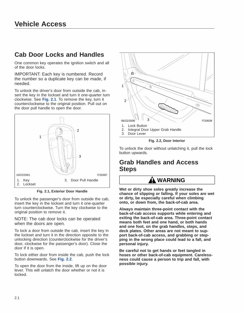
2. Using both hands, grasp the grab handle that ison the B-pillar, or use your left hand on the inte-gral door lower grab handle. See Fig. 2.3 . Reachup as far as is comfortable.
3. Place your right foot on the bottom step, and pullyourself up. Move your left hand to the integraldoor upper grab handle.
4. Place your left foot on the top step.
5. Grasp the steering wheel with your left hand, andstep up.
6. Step into the cab with your right foot first, andgrasp the steering wheel with your right hand.
Exiting the Driver SideExit the cab from the driver side as follows:
IMPORTANT: Do not attempt to exit the cabwhile carrying any items in your hands.
1. Grasp the steering wheel with both hands, placeyour left foot on the top step, then stand on thethreshold facing into the cab.
2. Using your right hand, grasp the grab handle,located on the B-pillar.
3. Move your right foot to the bottom step.
4. Move your left hand to the integral door lowergrab handle.
5. Step to the ground with your left foot first.
Entering the Passenger SideWhen entering the cab from the passenger side, usethe grab handles and access steps as follows:
1. Open the passenger-side door, and place any-thing that you are carrying in the cab.
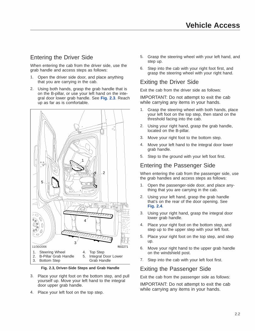
2. Using your left hand, grasp the grab handlethat’s on the rear of the door opening. SeeFig. 2.4 .
3. Using your right hand, grasp the integral doorlower grab handle.
4. Place your right foot on the bottom step, andstep up to the upper step with your left foot.
5. Place your right foot on the top step, and stepup.
6. Move your right hand to the upper grab handleon the windshield post.
7. Step into the cab with your left foot first.
Exiting the Passenger SideExit the cab from the passenger side as follows:
IMPORTANT: Do not attempt to exit the cabwhile carrying any items in your hands.
11/30/2006 f602271
1
2
3
4
5
1. Steering Wheel2. B-Pillar Grab Handle3. Bottom Step
4. Top Step5. Integral Door Lower
Grab Handle
Fig. 2.3, Driver-Side Steps and Grab Handle
Vehicle Access
2.2
1. Using both hands, grasp the grab handle thatson the windshield post, and place your right footon the top step while standing up from the seatfacing inward.
2. Place your left foot on the bottom step.
3. Move your left hand to the lower grab handlelocated at the rear edge of the door opening.See Fig. 2.4 .
4. Move your right hand to the integral door lowergrab handle.
5. Step to the ground with your right foot first.
Cab-to-Sleeper AccessTo open the sleeper access on vehicles with vinylsleeper curtains, unzip the sleeper curtains. If de-sired, unsnap the curtains all the way around thesides and top, and remove the curtains.
To open the sleeper access on vehicles with veloursleeper curtains, unfasten the snaps at one side,then push the curtain to the opposite side.
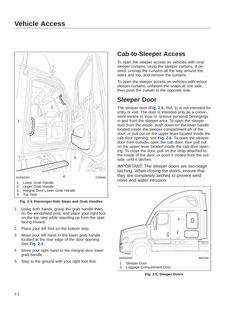
Sleeper DoorThe sleeper door (Fig. 2.5 , Ref. 1) is not intended forentry or exit. The door is intended only as a conve-nient means to stow or remove personal belongingsin and from the sleeper area. To open the sleeperdoor from the inside, push down on the lever handlelocated inside the sleeper compartment aft of thedoor, or pull out on the upper lever located inside thecab door opening; see Fig. 2.6 . To open the sleeperdoor from outside, open the cab door, then pull outon the upper lever located inside the cab door open-ing. To close the door, pull on the strap attached tothe inside of the door, or push it closed from the out-side, until it latches.
IMPORTANT: The sleeper doors are two-stagelatching. When closing the doors, ensure thatthey are completely latched to prevent windnoise and water intrusion.
01/03/2007 f720643
1
2
3
4
1. Lower Grab Handle2. Upper Grab Handle3. Integral Door Lower Grab Handle4. Top Step
Fig. 2.4, Passenger-Side Steps and Grab Handles
04/20/2007
1
2
f602302
1. Sleeper Door2. Luggage Compartment Door
Fig. 2.5, Sleeper Doors
Vehicle Access
2.3
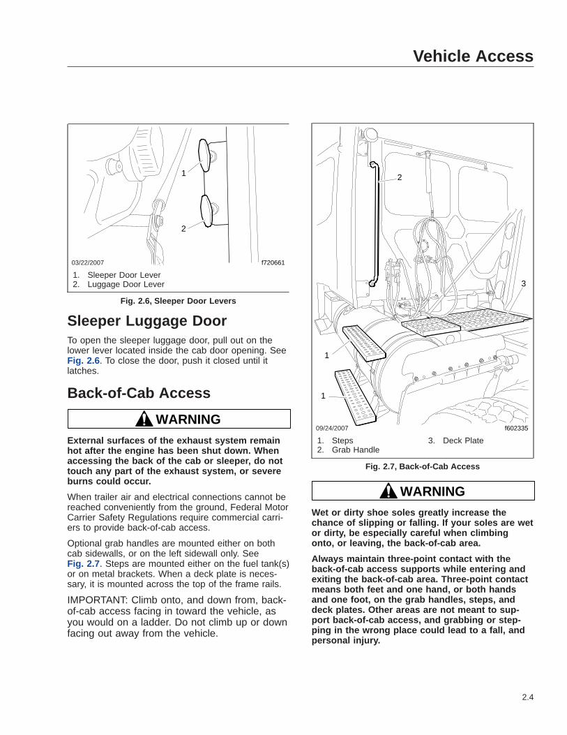
Sleeper Luggage DoorTo open the sleeper luggage door, pull out on thelower lever located inside the cab door opening. SeeFig. 2.6 . To close the door, push it closed until itlatches.
Back-of-Cab Access
WARNINGExternal surfaces of the exhaust system remainhot after the engine has been shut down. Whenaccessing the back of the cab or sleeper, do nottouch any part of the exhaust system, or severeburns could occur.
When trailer air and electrical connections cannot bereached conveniently from the ground, Federal MotorCarrier Safety Regulations require commercial carri-ers to provide back-of-cab access.
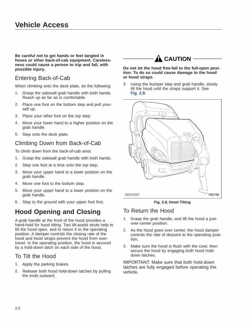
Optional grab handles are mounted either on bothcab sidewalls, or on the left sidewall only. SeeFig. 2.7 . Steps are mounted either on the fuel tank(s)or on metal brackets. When a deck plate is neces-sary, it is mounted across the top of the frame rails.
IMPORTANT: Climb onto, and down from, back-of-cab access facing in toward the vehicle, asyou would on a ladder. Do not climb up or downfacing out away from the vehicle.
WARNINGWet or dirty shoe soles greatly increase thechance of slipping or falling. If your soles are wetor dirty, be especially careful when climbingonto, or leaving, the back-of-cab area.
Always maintain three-point contact with theback-of-cab access supports while entering andexiting the back-of-cab area. Three-point contactmeans both feet and one hand, or both handsand one foot, on the grab handles, steps, anddeck plates. Other areas are not meant to sup-port back-of-cab access, and grabbing or step-ping in the wrong place could lead to a fall, andpersonal injury.
03/22/2007 f720661
1
2
1. Sleeper Door Lever2. Luggage Door Lever
Fig. 2.6, Sleeper Door Levers
09/24/2007 f602335
2
1
1
3
1. Steps2. Grab Handle
3. Deck Plate
Fig. 2.7, Back-of-Cab Access
Vehicle Access
2.4
Be careful not to get hands or feet tangled inhoses or other back-of-cab equipment. Careless-ness could cause a person to trip and fall, withpossible injury.
Entering Back-of-CabWhen climbing onto the deck plate, do the following:
1. Grasp the sidewall grab handle with both hands.Reach up as far as is comfortable.
2. Place one foot on the bottom step and pull your-self up.
3. Place your other foot on the top step.
4. Move your lower hand to a higher position on thegrab handle.
5. Step onto the deck plate.
Climbing Down from Back-of-CabTo climb down from the back-of-cab area:
1. Grasp the sidewall grab handle with both hands.
2. Step one foot at a time onto the top step.
3. Move your upper hand to a lower position on thegrab handle.
4. Move one foot to the bottom step.
5. Move your upper hand to a lower position on thegrab handle.
6. Step to the ground with your upper foot first.
Hood Opening and ClosingA grab handle at the front of the hood provides ahand-hold for hood tilting. Two tilt-assist struts help totilt the hood open, and to return it to the operatingposition. A damper controls the closing rate of thehood and hood straps prevent the hood from over-travel. In the operating position, the hood is securedby a hold-down latch on each side of the hood.
To Tilt the Hood1. Apply the parking brakes.
2. Release both hood hold-down latches by pullingthe ends outward.
CAUTIONDo not let the hood free-fall to the full-open posi-tion. To do so could cause damage to the hoodor hood straps.
3. Using the bumper step and grab handle, slowlytilt the hood until the straps support it. SeeFig. 2.8 .
To Return the Hood1. Grasp the grab handle, and lift the hood a just-
over-center position.
2. As the hood goes over center, the hood dampercontrols the rate of descent to the operating posi-tion.
3. Make sure the hood is flush with the cowl, thensecure the hood by engaging both hood hold-down latches.
IMPORTANT: Make sure that both hold-downlatches are fully engaged before operating thevehicle.
03/22/2007 f880788
Fig. 2.8, Hood Tilting
Vehicle Access
2.5
3
Electrical SystemElectrical System Overview . . . . . . . . . . . . . . . . . . . . . . . . . . . . . . . . . . . . . . . . . . . . . . . . . . . . . . . . . 3.1
Electrical System Overview
WARNINGDo not attempt to modify, add, splice, or removeelectrical wiring on this vehicle. Doing so coulddamage the electrical system and result in a firethat could cause serious personal injury or prop-erty damage.
The Cascadia™ electrical system is a multiplexeddesign. Multiplexing allows the electrical system tosimultaneously perform tasks and monitor compo-nents. The multiplexing system sharply reduces thenumber of wires on the vehicle by sharing wires formultiple components. Multiple electronic messagesare sent simultaneously through the same signalpath, called the datalink.
The multiplexed electrical system on Cascadia™ ve-hicles combines electronic devices called SAMs, withtraditional power distribution modules (PDMs) thathouse fuses and relays. The SAM Cab and SAMChassis monitor inputs from sensors and switches,and control power distribution to the electrical loadson the vehicle.
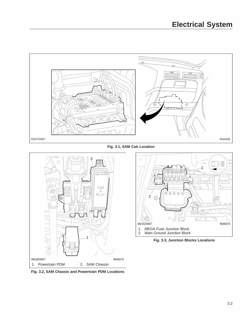
Electronic Power DistributionThe SAM Cab and SAM Chassis modules are elec-tronic control units that have power distribution com-ponents (fuses and relays) physically on them. Referto Chapter 25 for fuse and relay locations. The SAMCab is located behind the glovebox, on the passen-ger side. See Fig. 3.1 .
The SAM Chassis is located on the frontwall, on thedriver side. See Fig. 3.2 .
Electrical Power DistributionStandard electrical power distribution provides bat-tery power to the electronics system. The electricalpower distribution components on the Cascadia™
vehicle are:
• Powertrain PDM
• Trailer PDM
• Auxiliary PDM
• MEGA® Fuse junction block
• Main ground junction block
• Load disconnect switch
Powertrain PDMThe powertrain PDM provides battery and ignitionpower to the engine ECM, the exhaust aftertreatmentdevice (ATD), transmission (TCU), as well as otherpowertrain-related circuits. It is mounted in the en-gine compartment, above the quarter fender on thedriver side. See Fig. 3.2 .
Trailer PDMThe optional trailer PDM mounted on the frame rail isused to supply trailer power to the chassis-mountedtrailer receptacles. The SAM Chassis supplies controloutputs to the remote trailer PDM. The trailer PDM ispowered through the vehicle battery system.
Auxiliary PDMThis optional PDM is used when additional circuitprotection is needed for optional features. For ex-ample, if a beacon light is added to the Cascadia, itmay require an auxiliary PDM.
MEGA® Fuse Junction Block (MFJB)The MEGA Fuse junction block houses up to fiveMEGA Fuses. One fuse is used to provide power tothe engine and transmission, one to the SAM Cab,and one to the SAM Chassis. The remaining MEGAFuses may be used to power an optional trailer PDMand/or inverter. The MFJB is located on the leftframe rail in front of the batteries. The cab electricalsystem is fed from the battery through the MFJB re-gardless of the ignition switch position. This routingprovides the best power distribution to the vehicle.See Fig. 3.3 .
Main Ground Junction Block (MGJB)The MGJB is the main node for connecting groundreturns to the battery. It is located on the left framerail, ahead of the MEGA Fuse junction block. SeeFig. 3.3 .
Electrical System
3.1
f54494502/07/2007
Fig. 3.1, SAM Cab Location
06/18/2007 f545074
1
2
1. Powertrain PDM 2. SAM Chassis
Fig. 3.2, SAM Chassis and Powertrain PDM Locations
06/15/2007 f545073
1
2
1. MEGA Fuse Junction Block2. Main Ground Junction Block
Fig. 3.3, Junction Blocks Locations
Electrical System
3.2
Load Disconnect SwitchThe load disconnect switch is mounted in one ofthree locations:
• inside the cab on the left side of the driver’sseat (left-hand-drive vehicle);
• on the battery box;
• outboard mounted on the left frame rail.
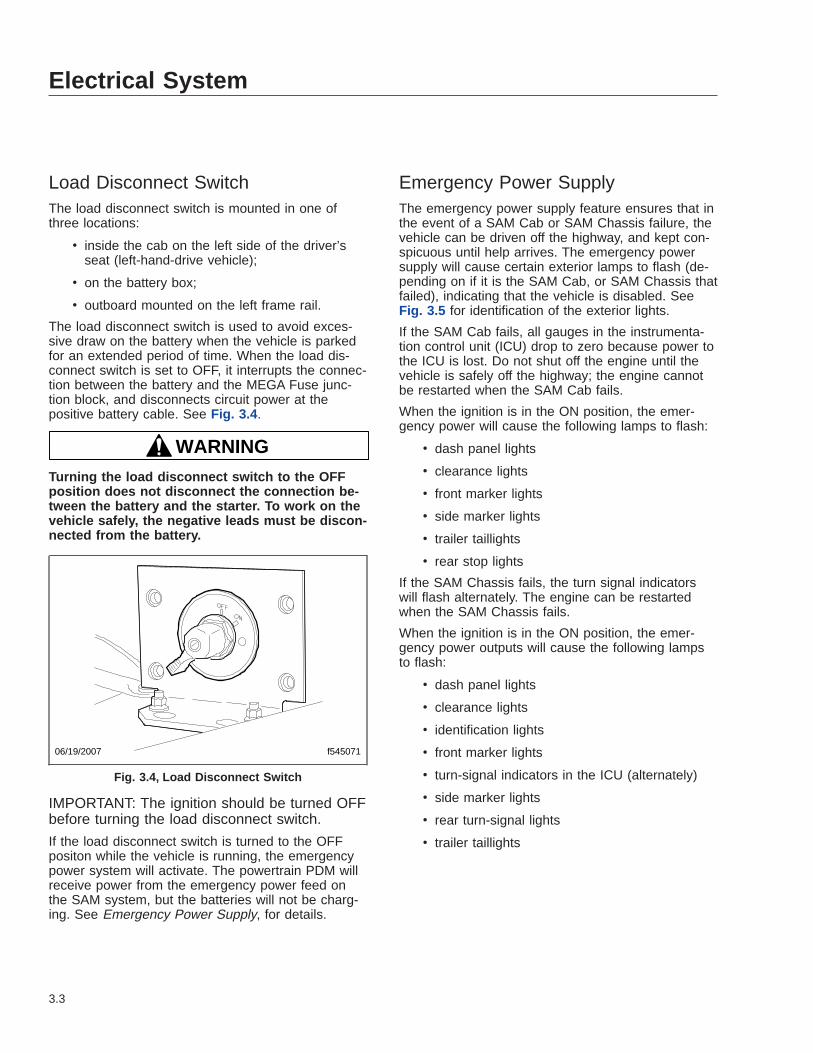
The load disconnect switch is used to avoid exces-sive draw on the battery when the vehicle is parkedfor an extended period of time. When the load dis-connect switch is set to OFF, it interrupts the connec-tion between the battery and the MEGA Fuse junc-tion block, and disconnects circuit power at thepositive battery cable. See Fig. 3.4 .
WARNINGTurning the load disconnect switch to the OFFposition does not disconnect the connection be-tween the battery and the starter. To work on thevehicle safely, the negative leads must be discon-nected from the battery.
IMPORTANT: The ignition should be turned OFFbefore turning the load disconnect switch.
If the load disconnect switch is turned to the OFFpositon while the vehicle is running, the emergencypower system will activate. The powertrain PDM willreceive power from the emergency power feed onthe SAM system, but the batteries will not be charg-ing. See Emergency Power Supply, for details.
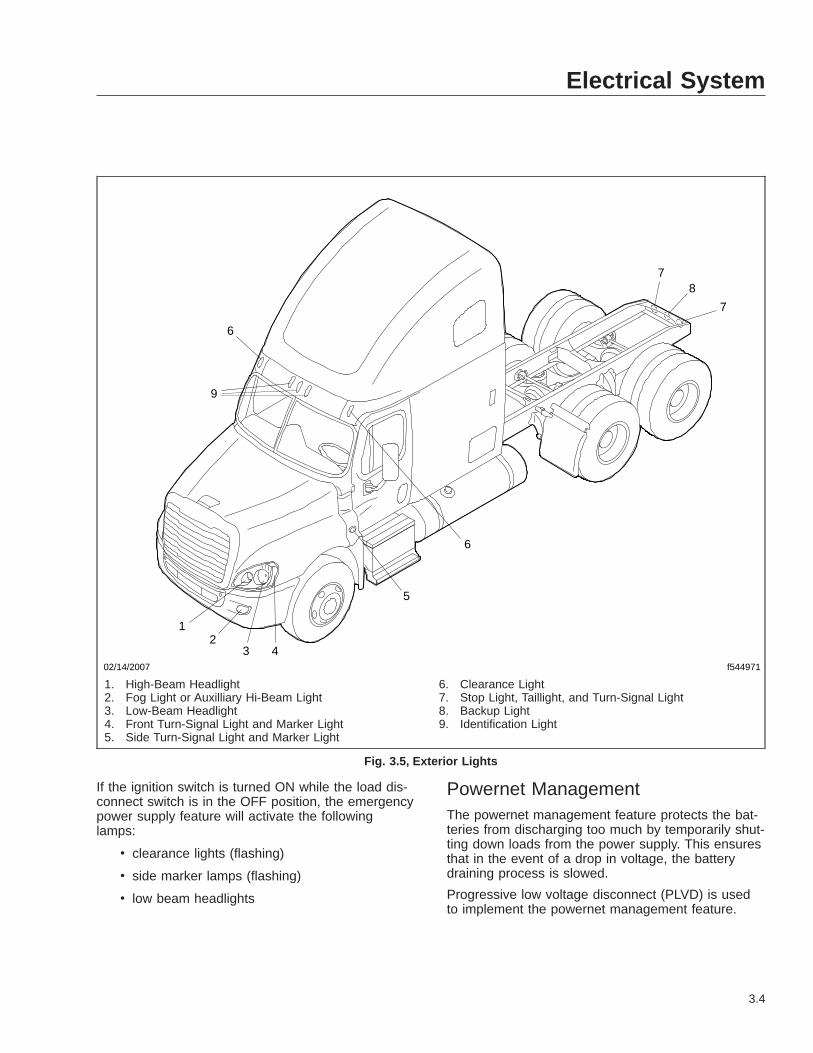
Emergency Power SupplyThe emergency power supply feature ensures that inthe event of a SAM Cab or SAM Chassis failure, thevehicle can be driven off the highway, and kept con-spicuous until help arrives. The emergency powersupply will cause certain exterior lamps to flash (de-pending on if it is the SAM Cab, or SAM Chassis thatfailed), indicating that the vehicle is disabled. SeeFig. 3.5 for identification of the exterior lights.
If the SAM Cab fails, all gauges in the instrumenta-tion control unit (ICU) drop to zero because power tothe ICU is lost. Do not shut off the engine until thevehicle is safely off the highway; the engine cannotbe restarted when the SAM Cab fails.
When the ignition is in the ON position, the emer-gency power will cause the following lamps to flash:
• dash panel lights
• clearance lights
• front marker lights
• side marker lights
• trailer taillights
• rear stop lights
If the SAM Chassis fails, the turn signal indicatorswill flash alternately. The engine can be restartedwhen the SAM Chassis fails.
When the ignition is in the ON position, the emer-gency power outputs will cause the following lampsto flash:
• dash panel lights
• clearance lights
• identification lights
• front marker lights
• turn-signal indicators in the ICU (alternately)
• side marker lights
• rear turn-signal lights
• trailer taillights
06/19/2007 f545071
Fig. 3.4, Load Disconnect Switch
Electrical System
3.3
If the ignition switch is turned ON while the load dis-connect switch is in the OFF position, the emergencypower supply feature will activate the followinglamps:
• clearance lights (flashing)
• side marker lamps (flashing)
• low beam headlights
Powernet ManagementThe powernet management feature protects the bat-teries from discharging too much by temporarily shut-ting down loads from the power supply. This ensuresthat in the event of a drop in voltage, the batterydraining process is slowed.
Progressive low voltage disconnect (PLVD) is usedto implement the powernet management feature.
02/14/2007 f544971
12
3 4
5
6
6
7
78
9
1. High-Beam Headlight2. Fog Light or Auxilliary Hi-Beam Light3. Low-Beam Headlight4. Front Turn-Signal Light and Marker Light5. Side Turn-Signal Light and Marker Light
6. Clearance Light7. Stop Light, Taillight, and Turn-Signal Light8. Backup Light9. Identification Light
Fig. 3.5, Exterior Lights
Electrical System
3.4
When the battery voltage drops below a predeter-mined value, loads designated as comfort loads (pri-ority level I) are shut down first. Then loads desig-nated as house loads (priority level II) are shut down.If necessary, basic loads (priority level III) are shutdown last.
The progressive shutdown of loads from comfortloads, to house loads, to basic loads allows thedriver to continue using critical loads, while noncriti-cal loads are temporarily unavailable. Calculations fordisconnecting loads are based on battery voltage,ignition switch status, and engine RPM. Also, a timedelay is implemented for the shutdown and reactiva-tion of loads to avoid unnecessary cycling of loadswhen battery voltage is close to the shutdown thresh-olds.
The SAM Cab reads the battery voltage via a dedi-cated sense pin that is fused in the powertrain PDMand not at the MFJB.
One minute before the comfort loads and houseloads are shut down, an alarm sounds for 10 sec-onds. No alarm sounds before the basic loads shutdown.
If the interior lights have been shut down by PLVD,pressing one of the interior light switches (ifequipped) brings the interior lights back on.
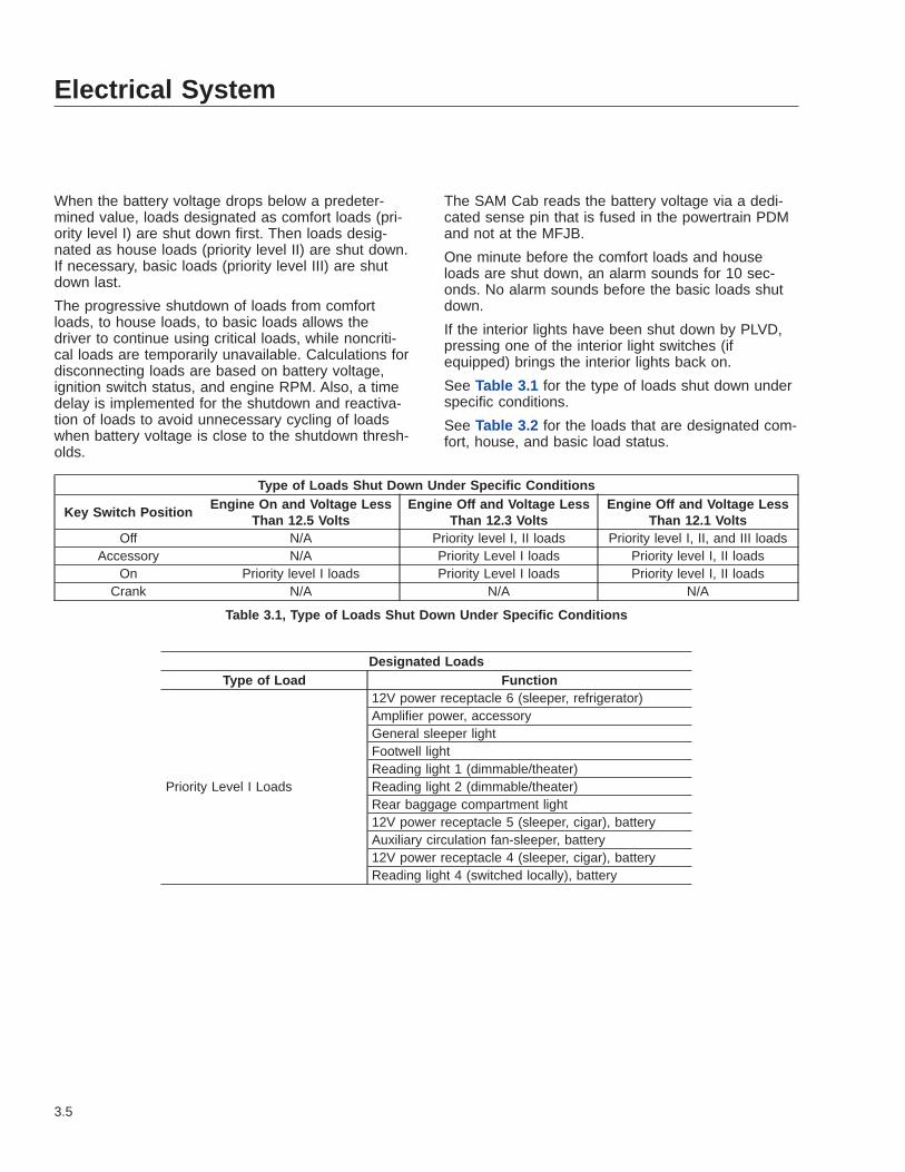
See Table 3.1 for the type of loads shut down underspecific conditions.
See Table 3.2 for the loads that are designated com-fort, house, and basic load status.
Type of Loads Shut Down Under Specific Conditions
Key Switch PositionEngine On and Voltage Less
Than 12.5 VoltsEngine Off and Voltage Less
Than 12.3 VoltsEngine Off and Voltage Less
Than 12.1 VoltsOff N/A Priority level I, II loads Priority level I, II, and III loads
Accessory N/A Priority Level I loads Priority level I, II loadsOn Priority level I loads Priority Level I loads Priority level I, II loads
Crank N/A N/A N/A
Table 3.1, Type of Loads Shut Down Under Specific Conditions
Designated LoadsType of Load Function
Priority Level I Loads
12V power receptacle 6 (sleeper, refrigerator)Amplifier power, accessoryGeneral sleeper lightFootwell lightReading light 1 (dimmable/theater)Reading light 2 (dimmable/theater)Rear baggage compartment light12V power receptacle 5 (sleeper, cigar), batteryAuxiliary circulation fan-sleeper, battery12V power receptacle 4 (sleeper, cigar), batteryReading light 4 (switched locally), battery
Electrical System
3.5
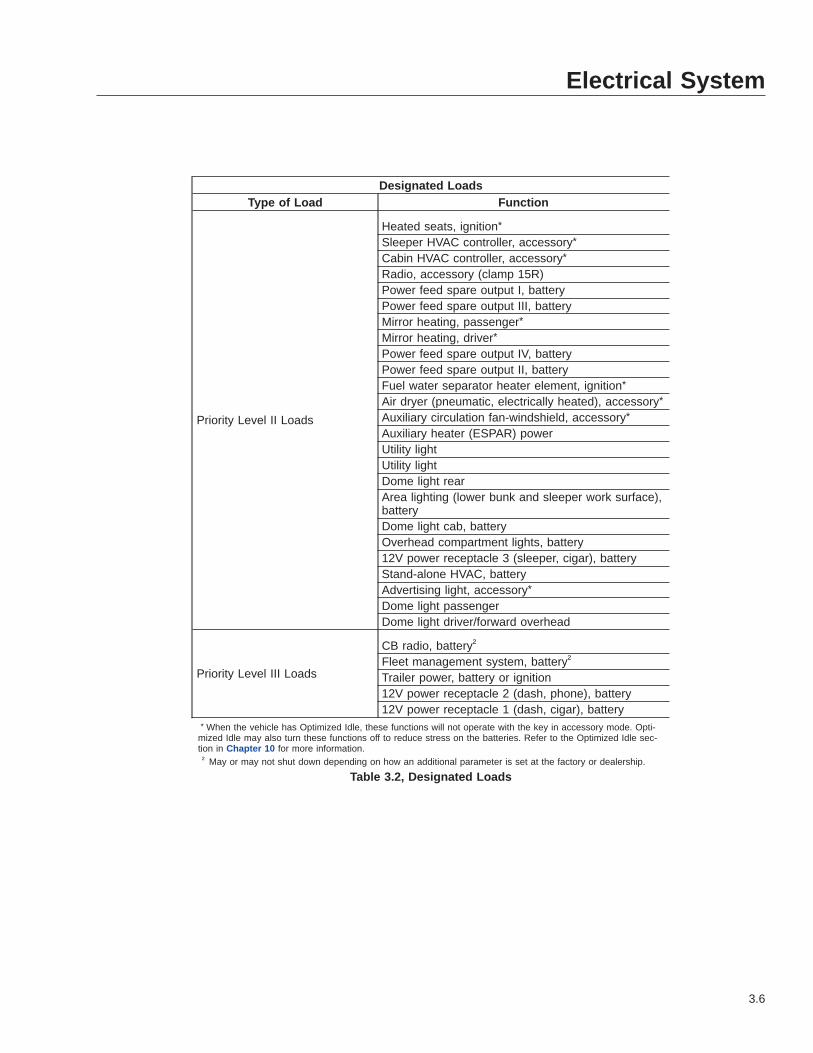
Designated LoadsType of Load Function
Priority Level II Loads
Heated seats, ignition*
Sleeper HVAC controller, accessory*
Cabin HVAC controller, accessory*
Radio, accessory (clamp 15R)Power feed spare output I, batteryPower feed spare output III, batteryMirror heating, passenger*
Mirror heating, driver*
Power feed spare output IV, batteryPower feed spare output II, batteryFuel water separator heater element, ignition*
Air dryer (pneumatic, electrically heated), accessory*
Auxiliary circulation fan-windshield, accessory*
Auxiliary heater (ESPAR) powerUtility lightUtility lightDome light rearArea lighting (lower bunk and sleeper work surface),batteryDome light cab, batteryOverhead compartment lights, battery12V power receptacle 3 (sleeper, cigar), batteryStand-alone HVAC, batteryAdvertising light, accessory*
Dome light passengerDome light driver/forward overhead
Priority Level III Loads
CB radio, battery†
Fleet management system, battery†
Trailer power, battery or ignition12V power receptacle 2 (dash, phone), battery12V power receptacle 1 (dash, cigar), battery
* When the vehicle has Optimized Idle, these functions will not operate with the key in accessory mode. Opti-mized Idle may also turn these functions off to reduce stress on the batteries. Refer to the Optimized Idle sec-tion in Chapter 10 for more information.† May or may not shut down depending on how an additional parameter is set at the factory or dealership.
Table 3.2, Designated Loads
Electrical System
3.6
4
InstrumentsICU3-P3 (Instrumentation Control Unit) . . . . . . . . . . . . . . . . . . . . . . . . . . . . . . . . . . . . . . . . . . . . . . . . 4.1ICU4-P3 (Instrumentation Control Unit) . . . . . . . . . . . . . . . . . . . . . . . . . . . . . . . . . . . . . . . . . . . . . . . . 4.5ICU4M-P3 (Instrumentation Control Unit) . . . . . . . . . . . . . . . . . . . . . . . . . . . . . . . . . . . . . . . . . . . . . 4.10Warning and Indicator Lights . . . . . . . . . . . . . . . . . . . . . . . . . . . . . . . . . . . . . . . . . . . . . . . . . . . . . . . 4.23Overhead Instrument Panel . . . . . . . . . . . . . . . . . . . . . . . . . . . . . . . . . . . . . . . . . . . . . . . . . . . . . . . . 4.25Speedometer and Tachometer . . . . . . . . . . . . . . . . . . . . . . . . . . . . . . . . . . . . . . . . . . . . . . . . . . . . . . 4.25Standard Instruments . . . . . . . . . . . . . . . . . . . . . . . . . . . . . . . . . . . . . . . . . . . . . . . . . . . . . . . . . . . . . 4.25Optional Instruments . . . . . . . . . . . . . . . . . . . . . . . . . . . . . . . . . . . . . . . . . . . . . . . . . . . . . . . . . . . . . 4.27Collision Warning System, Eaton VORAD VS-400 (Stand Alone) . . . . . . . . . . . . . . . . . . . . . . . . . . 4.29Roll-Stability Advisor/Control, and Hard-Braking Advisor . . . . . . . . . . . . . . . . . . . . . . . . . . . . . . . . . 4.37
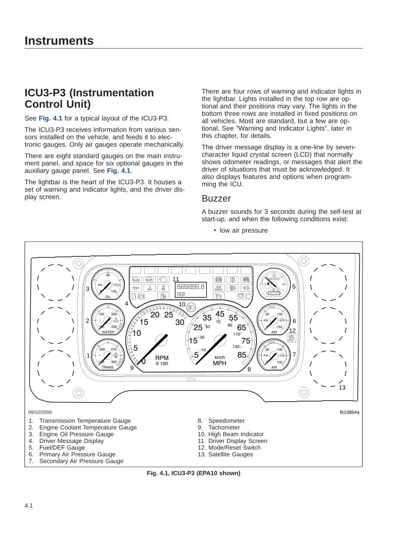
ICU3-P3 (InstrumentationControl Unit)See Fig. 4.1 for a typical layout of the ICU3-P3.
The ICU3-P3 receives information from various sen-sors installed on the vehicle, and feeds it to elec-tronic gauges. Only air gauges operate mechanically.
There are eight standard gauges on the main instru-ment panel, and space for six optional gauges in theauxiliary gauge panel. See Fig. 4.1 .
The lightbar is the heart of the ICU3-P3. It houses aset of warning and indicator lights, and the driver dis-play screen.
There are four rows of warning and indicator lights inthe lightbar. Lights installed in the top row are op-tional and their positions may vary. The lights in thebottom three rows are installed in fixed positions onall vehicles. Most are standard, but a few are op-tional. See "Warning and Indicator Lights", later inthis chapter, for details.
The driver message display is a one-line by seven-character liquid crystal screen (LCD) that normallyshows odometer readings, or messages that alert thedriver of situations that must be acknowledged. Italso displays features and options when program-ming the ICU.
BuzzerA buzzer sounds for 3 seconds during the self-test atstart-up, and when the following conditions exist:
• low air pressure
09/10/2009 f610864a
1
2
3
4
5
6
7
89
13
10
11
12
1. Transmission Temperature Gauge2. Engine Coolant Temperature Gauge3. Engine Oil Pressure Gauge4. Driver Message Display5. Fuel/DEF Gauge6. Primary Air Pressure Gauge7. Secondary Air Pressure Gauge
8. Speedometer9. Tachometer10. High Beam Indicator11. Driver Display Screen12. Mode/Reset Switch13. Satellite Gauges
Fig. 4.1, ICU3-P3 (EPA10 shown)
Instruments
4.1
• low oil pressure
• high coolant temperature
• the parking brake is applied and the vehicle ismoving at a speed of at least 2 mph (3 km/h)
While the vehicle is being driven, if the outside airtemperature drops to 34°F (1°C) or less, the mes-sage display will flash the temperature, and a warn-ing chime will sound for 5 seconds if the ambienttemperature alarm is enabled.
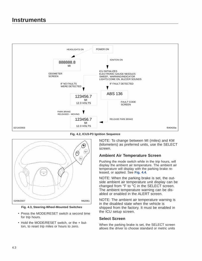
ICU3-P3 Ignition SequenceIf the headlights are turned on, the driver messagedisplay shows the odometer reading until the ignitionis turned on.
When the ignition is turned on, the electronic gaugescomplete a full sweep of their dials, the warning andindicator lights illuminate, and the buzzer sounds for3 seconds.
NOTE: The air gauges do not sweep.
The following lights illuminate during the ignition se-quence:
• Fasten Seat Belt Warning
• Low Battery Voltage Warning
• High Coolant Temperature Warning
• Low Engine Oil Pressure Warning
• Low Air Pressure Warning
• Parking Brake On Indicator
• All engine warning lights, including engine pro-tection, check engine, and (Cummins only)stop engine
• All ABS warning lights, including wheel spin,tractor ABS, and (if installed) trailer ABS
See Fig. 4.2 for the ICU3-P3 ignition sequence.
NOTE: The engine and ABS warning lights illu-minate during the ignition sequence, but theyare controlled by an independent ECU (elec-tronic control unit), not by the ICU3-P3.
When the ignition switch is turned on, the ICU3-P3performs a self-test, and looks for active faults. Dur-ing the first half of the self-test, all segments of thedisplay illuminate as follows: "888888.8." TheICU3-P3 voltmeter display illuminates with the value
"8.8." During the second half of the self-test, the soft-ware revision level is displayed.
If there are no active faults, the ICU3-P3 displays theodometer reading. However, if the ICU3-P3 has re-ceived active fault codes from other devices, it dis-plays them one after the other until the parking brakeis released or the ignition switch is turned off. Oncethe parking brake is released, the ICU3-P3 displaysthe odometer reading again.
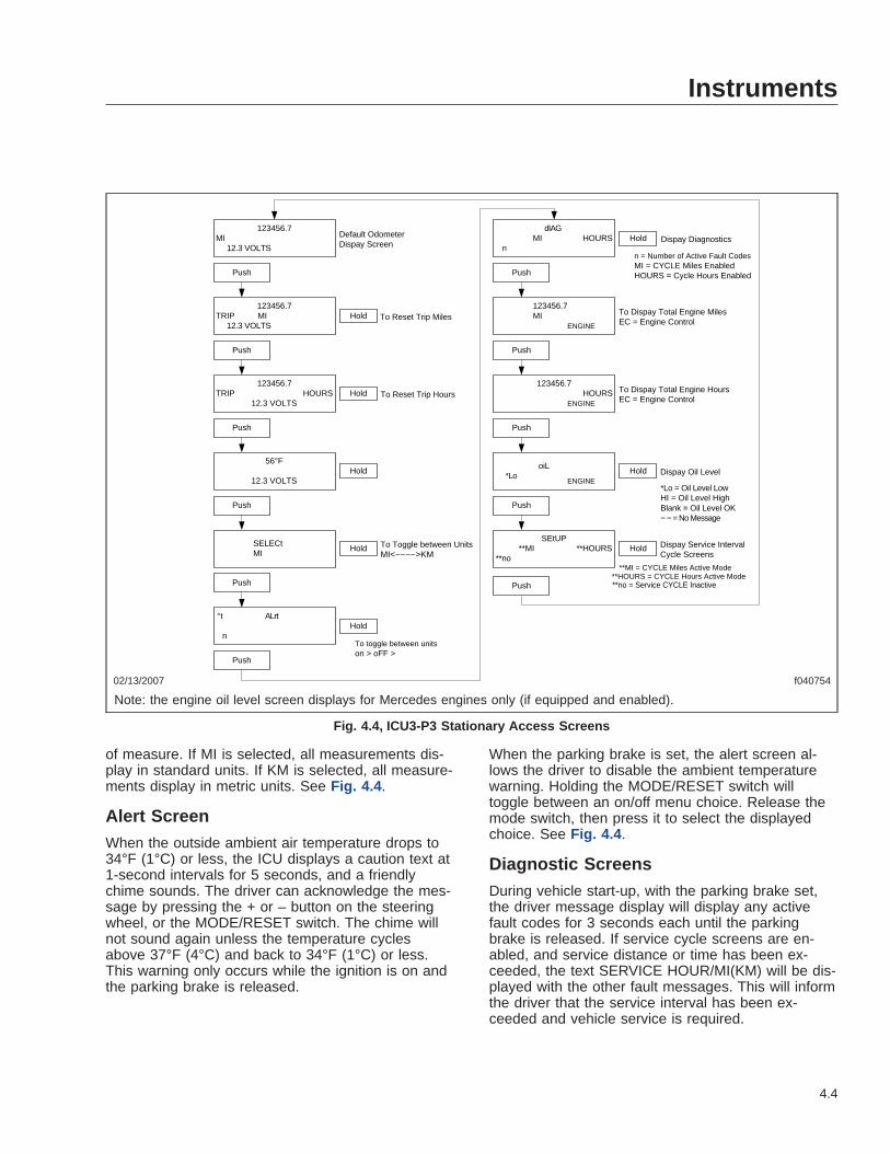
Mode/Reset SwitchA MODE/RESET switch is located on the right sideof the ICU3-P3 instrument cluster. See Fig. 4.1 . TheMODE/RESET switch is used to scroll through thescreens on the driver message display, and to resetfeatures such as trip counters, miles or kilometersunits, and the ambient temperature alarm. Pressingthe MODE/RESET button advances the display tothe next feature. Holding the button scrolls to a menuchoice, then releasing it at the preferred choice andpressing the MODE/RESET switch will reset the dis-play. When the display is reset, an audible chirp isheard.
The driver message display screens can also bescrolled through using the switches mounted on thesteering wheel. See Fig. 4.3 . Use the + button toscroll up, and use the – button to scroll down. The +button can be be held to reset or select a menuchoice, instead of the MODE/RESET button, for anyscreen.
When the ignition sequence is completed, if the park-ing brake is released, the driver message display willcycle through the trip information screens and theambient air temperature display screen only. Theparking brake must be set to access the stationaryaccess screens, i.e. SELECT, ALERT, DIAGNOSTIC,ENGINE, OIL LVL (if available) and SETUP screens.
See Fig. 4.4 for a diagram of the stationary accessscreens.
Trip Information ScreensTrip information allows you to view trip mileage andtime. Trip information screens will display with theparking brake released, or applied.
When the odometer reading is displayed:
• Press the MODE/RESET switch once for tripdistance.
Instruments
4.2
• Press the MODE/RESET switch a second timefor trip hours.
• Hold the MODE/RESET switch, or the + but-ton, to reset trip miles or hours to zero.
NOTE: To change between MI (miles) and KM(kilometers) as preferred units, use the SELECTscreen.
Ambient Air Temperature ScreenPushing the mode switch while in the trip hours, willdisplay the ambient air temperature. The ambient airtemperature will display with the parking brake re-leased, or applied. See Fig. 4.4 .
NOTE: When the parking brake is set, the out-side ambient air temperature unit display can bechanged from °F to °C in the SELECT screen.The ambient temperature warning can be dis-abled or enabled in the ALERT screen.
NOTE: The ambient air temperature warning isin the disabled state when the vehicle isshipped from the factory. It must be enabled inthe ICU setup screen.
Select ScreenWhen the parking brake is set, the SELECT screenallows the driver to choose standard or metric units
POWER ON
PARK BRAKE
IGNITION ON
HEADLIGHTS ON
RELEASE PARK BRAKE
f040420a02/14/2003
RELEASED − MOVING
FAULT CODESCREEN
IF NO FAULTSWERE DETECTED
ELECTRONIC GAUGE NEEDLESSWEEP, WARNING/INDICATORLIGHTS COME ON, BUZZER SOUNDS
IF FAULT DETECTED
ICU INITIALIZES
888888.8
ABS 136
ODOMETERSCREEN
123456.7
12.3 VOLTS
123456.7
12.3 VOLTS
MI
MI
MI
Fig. 4.2, ICU3-P3 Ignition Sequence
MRKRINT
ENGBRK
−
+
02/06/2007 f462061
Fig. 4.3, Steering-Wheel-Mounted Switches
Instruments
4.3
of measure. If MI is selected, all measurements dis-play in standard units. If KM is selected, all measure-ments display in metric units. See Fig. 4.4 .
Alert ScreenWhen the outside ambient air temperature drops to34°F (1°C) or less, the ICU displays a caution text at1-second intervals for 5 seconds, and a friendlychime sounds. The driver can acknowledge the mes-sage by pressing the + or – button on the steeringwheel, or the MODE/RESET switch. The chime willnot sound again unless the temperature cyclesabove 37°F (4°C) and back to 34°F (1°C) or less.This warning only occurs while the ignition is on andthe parking brake is released.
When the parking brake is set, the alert screen al-lows the driver to disable the ambient temperaturewarning. Holding the MODE/RESET switch willtoggle between an on/off menu choice. Release themode switch, then press it to select the displayedchoice. See Fig. 4.4 .
Diagnostic ScreensDuring vehicle start-up, with the parking brake set,the driver message display will display any activefault codes for 3 seconds each until the parkingbrake is released. If service cycle screens are en-abled, and service distance or time has been ex-ceeded, the text SERVICE HOUR/MI(KM) will be dis-played with the other fault messages. This will informthe driver that the service interval has been ex-ceeded and vehicle service is required.
02/13/2007 f040754
123456.7TRIP MI 12.3 VOLTS
Push
123456.7MI 12.3 VOLTS
Push
123456.7TRIP HOURS
12.3 VOLTS
SELECtMI
ALrt
n
123456.7MI
ENGINE
123456.7HOURS
ENGINE
oiL *Lo
SEtUP **MI **HOURS**no
Default OdometerDispay Screen
To Reset Trip MilesHold
To Reset Trip HoursHold
To Toggle between Units
Hold
Hold
Dispay Oil LevelHold
Dispay Service IntervalCycle Screens
Hold
To Dispay Total Engine HoursEC = Engine Control
To Dispay Total Engine MilesEC = Engine Control
Hold
Push
To toggle between unitson > oFF >
*Lo = Oil Level LowHI = Oil Level HighBlank = Oil Level OK− − = No Message
MI<−−−−>KM
**MI = CYCLE Miles Active Mode**HOURS = CYCLE Hours Active Mode**no = Service CYCLE Inactive
dIAGMI HOURS
nDispay Diagnostics
Hold
n = Number of Active Fault CodesMI = CYCLE Miles EnabledHOURS = Cycle Hours Enabled
°t
ENGINE
Push
Push
Push
Push
Push
Push
Push
Push
12.3 VOLTS
56°F
Note: the engine oil level screen displays for Mercedes engines only (if equipped and enabled).
Fig. 4.4, ICU3-P3 Stationary Access Screens
Instruments
4.4
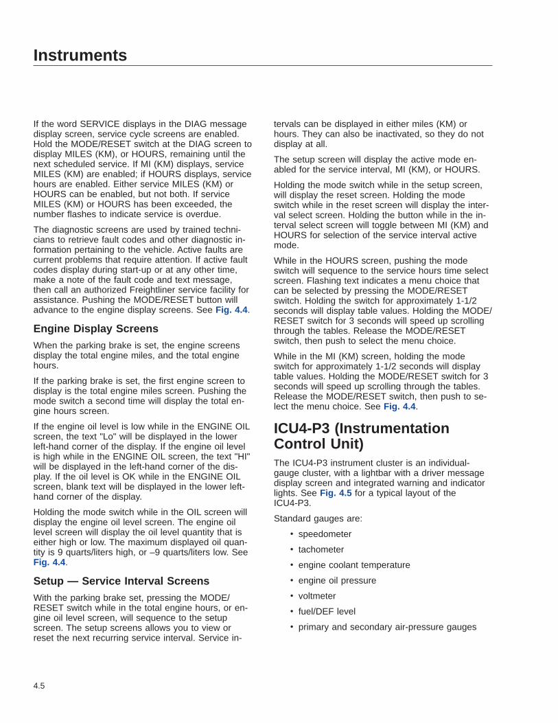
If the word SERVICE displays in the DIAG messagedisplay screen, service cycle screens are enabled.Hold the MODE/RESET switch at the DIAG screen todisplay MILES (KM), or HOURS, remaining until thenext scheduled service. If MI (KM) displays, serviceMILES (KM) are enabled; if HOURS displays, servicehours are enabled. Either service MILES (KM) orHOURS can be enabled, but not both. If serviceMILES (KM) or HOURS has been exceeded, thenumber flashes to indicate service is overdue.
The diagnostic screens are used by trained techni-cians to retrieve fault codes and other diagnostic in-formation pertaining to the vehicle. Active faults arecurrent problems that require attention. If active faultcodes display during start-up or at any other time,make a note of the fault code and text message,then call an authorized Freightliner service facility forassistance. Pushing the MODE/RESET button willadvance to the engine display screens. See Fig. 4.4 .
Engine Display ScreensWhen the parking brake is set, the engine screensdisplay the total engine miles, and the total enginehours.
If the parking brake is set, the first engine screen todisplay is the total engine miles screen. Pushing themode switch a second time will display the total en-gine hours screen.
If the engine oil level is low while in the ENGINE OILscreen, the text "Lo" will be displayed in the lowerleft-hand corner of the display. If the engine oil levelis high while in the ENGINE OIL screen, the text "HI"will be displayed in the left-hand corner of the dis-play. If the oil level is OK while in the ENGINE OILscreen, blank text will be displayed in the lower left-hand corner of the display.
Holding the mode switch while in the OIL screen willdisplay the engine oil level screen. The engine oillevel screen will display the oil level quantity that iseither high or low. The maximum displayed oil quan-tity is 9 quarts/liters high, or –9 quarts/liters low. SeeFig. 4.4 .
Setup — Service Interval ScreensWith the parking brake set, pressing the MODE/RESET switch while in the total engine hours, or en-gine oil level screen, will sequence to the setupscreen. The setup screens allows you to view orreset the next recurring service interval. Service in-
tervals can be displayed in either miles (KM) orhours. They can also be inactivated, so they do notdisplay at all.
The setup screen will display the active mode en-abled for the service interval, MI (KM), or HOURS.
Holding the mode switch while in the setup screen,will display the reset screen. Holding the modeswitch while in the reset screen will display the inter-val select screen. Holding the button while in the in-terval select screen will toggle between MI (KM) andHOURS for selection of the service interval activemode.
While in the HOURS screen, pushing the modeswitch will sequence to the service hours time selectscreen. Flashing text indicates a menu choice thatcan be selected by pressing the MODE/RESETswitch. Holding the switch for approximately 1-1/2seconds will display table values. Holding the MODE/RESET switch for 3 seconds will speed up scrollingthrough the tables. Release the MODE/RESETswitch, then push to select the menu choice.
While in the MI (KM) screen, holding the modeswitch for approximately 1-1/2 seconds will displaytable values. Holding the MODE/RESET switch for 3seconds will speed up scrolling through the tables.Release the MODE/RESET switch, then push to se-lect the menu choice. See Fig. 4.4 .
ICU4-P3 (InstrumentationControl Unit)The ICU4-P3 instrument cluster is an individual-gauge cluster, with a lightbar with a driver messagedisplay screen and integrated warning and indicatorlights. See Fig. 4.5 for a typical layout of theICU4-P3.
Standard gauges are:
• speedometer
• tachometer
• engine coolant temperature
• engine oil pressure
• voltmeter
• fuel/DEF level
• primary and secondary air-pressure gauges
Instruments
4.5
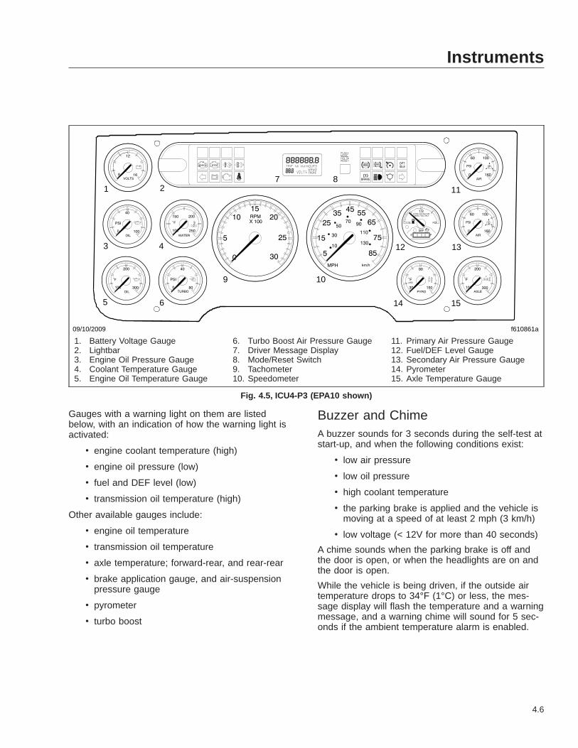
Gauges with a warning light on them are listedbelow, with an indication of how the warning light isactivated:
• engine coolant temperature (high)
• engine oil pressure (low)
• fuel and DEF level (low)
• transmission oil temperature (high)
Other available gauges include:
• engine oil temperature
• transmission oil temperature
• axle temperature; forward-rear, and rear-rear
• brake application gauge, and air-suspensionpressure gauge
• pyrometer
• turbo boost
Buzzer and ChimeA buzzer sounds for 3 seconds during the self-test atstart-up, and when the following conditions exist:
• low air pressure
• low oil pressure
• high coolant temperature
• the parking brake is applied and the vehicle ismoving at a speed of at least 2 mph (3 km/h)
• low voltage (< 12V for more than 40 seconds)
A chime sounds when the parking brake is off andthe door is open, or when the headlights are on andthe door is open.
While the vehicle is being driven, if the outside airtemperature drops to 34°F (1°C) or less, the mes-sage display will flash the temperature and a warningmessage, and a warning chime will sound for 5 sec-onds if the ambient temperature alarm is enabled.
09/10/2009 f610861a
1
3 4
5 6
7 8
9 10
11
12 13
14 15
2
1. Battery Voltage Gauge2. Lightbar3. Engine Oil Pressure Gauge4. Coolant Temperature Gauge5. Engine Oil Temperature Gauge
6. Turbo Boost Air Pressure Gauge7. Driver Message Display8. Mode/Reset Switch9. Tachometer10. Speedometer
11. Primary Air Pressure Gauge12. Fuel/DEF Level Gauge13. Secondary Air Pressure Gauge14. Pyrometer15. Axle Temperature Gauge
Fig. 4.5, ICU4-P3 (EPA10 shown)
Instruments
4.6
Ignition SequenceWhen the ignition key is turned on, the ICU4-P3 be-gins a self-test. During this process, all gauges con-trolled by the cluster sweep to full scale and return,the buzzer sounds for 3 seconds, the fasten seat beltwarning light illuminates for 15 seconds, and the bat-tery voltage, low air pressure, and parking brakewarning lights illuminate then turn off. Then the soft-ware revision level of the ICU4 is displayed, followedby active faults, if any, then the odometer display.
Mode/Reset SwitchThe mode/reset switch is located on the lightbar. SeeFig. 4.5 . It controls the driver message display.Pressing the mode/reset button advances onescreen, holding the button selects a menu choice orresets the display. When the display is reset, an au-dible chirp is heard.
The message display screens can also be scrolledthrough by using the switches mounted on the steer-ing wheel. See Fig. 4.3 . Use the + button to scrollup, and use the – button to scroll down. The + buttoncan be be held to reset or select a menu choice, in-stead of the mode/reset button, for any screen.
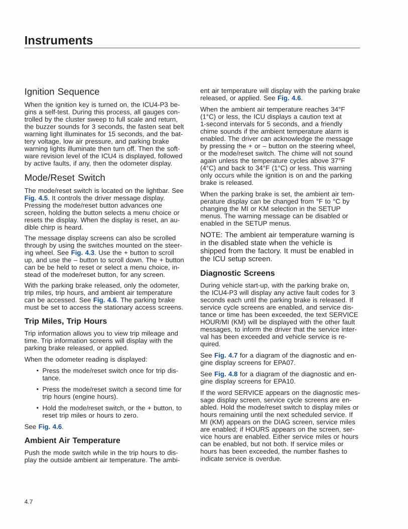
With the parking brake released, only the odometer,trip miles, trip hours, and ambient air temperaturecan be accessed. See Fig. 4.6 . The parking brakemust be set to access the stationary access screens.
Trip Miles, Trip HoursTrip information allows you to view trip mileage andtime. Trip information screens will display with theparking brake released, or applied.
When the odometer reading is displayed:
• Press the mode/reset switch once for trip dis-tance.
• Press the mode/reset switch a second time fortrip hours (engine hours).
• Hold the mode/reset switch, or the + button, toreset trip miles or hours to zero.
See Fig. 4.6 .
Ambient Air TemperaturePush the mode switch while in the trip hours to dis-play the outside ambient air temperature. The ambi-
ent air temperature will display with the parking brakereleased, or applied. See Fig. 4.6 .
When the ambient air temperature reaches 34°F(1°C) or less, the ICU displays a caution text at1-second intervals for 5 seconds, and a friendlychime sounds if the ambient temperature alarm isenabled. The driver can acknowledge the messageby pressing the + or – button on the steering wheel,or the mode/reset switch. The chime will not soundagain unless the temperature cycles above 37°F(4°C) and back to 34°F (1°C) or less. This warningonly occurs while the ignition is on and the parkingbrake is released.
When the parking brake is set, the ambient air tem-perature display can be changed from °F to °C bychanging the MI or KM selection in the SETUPmenus. The warning message can be disabled orenabled in the SETUP menus.
NOTE: The ambient air temperature warning isin the disabled state when the vehicle isshipped from the factory. It must be enabled inthe ICU setup screen.
Diagnostic ScreensDuring vehicle start-up, with the parking brake on,the ICU4-P3 will display any active fault codes for 3seconds each until the parking brake is released. Ifservice cycle screens are enabled, and service dis-tance or time has been exceeded, the text SERVICEHOUR/MI (KM) will be displayed with the other faultmessages, to inform the driver that the service inter-val has been exceeded and vehicle service is re-quired.
See Fig. 4.7 for a diagram of the diagnostic and en-gine display screens for EPA07.
See Fig. 4.8 for a diagram of the diagnostic and en-gine display screens for EPA10.
If the word SERVICE appears on the diagnostic mes-sage display screen, service cycle screens are en-abled. Hold the mode/reset switch to display miles orhours remaining until the next scheduled service. IfMI (KM) appears on the DIAG screen, service milesare enabled; if HOURS appears on the screen, ser-vice hours are enabled. Either service miles or hourscan be enabled, but not both. If service miles orhours has been exceeded, the number flashes toindicate service is overdue.
Instruments
4.7
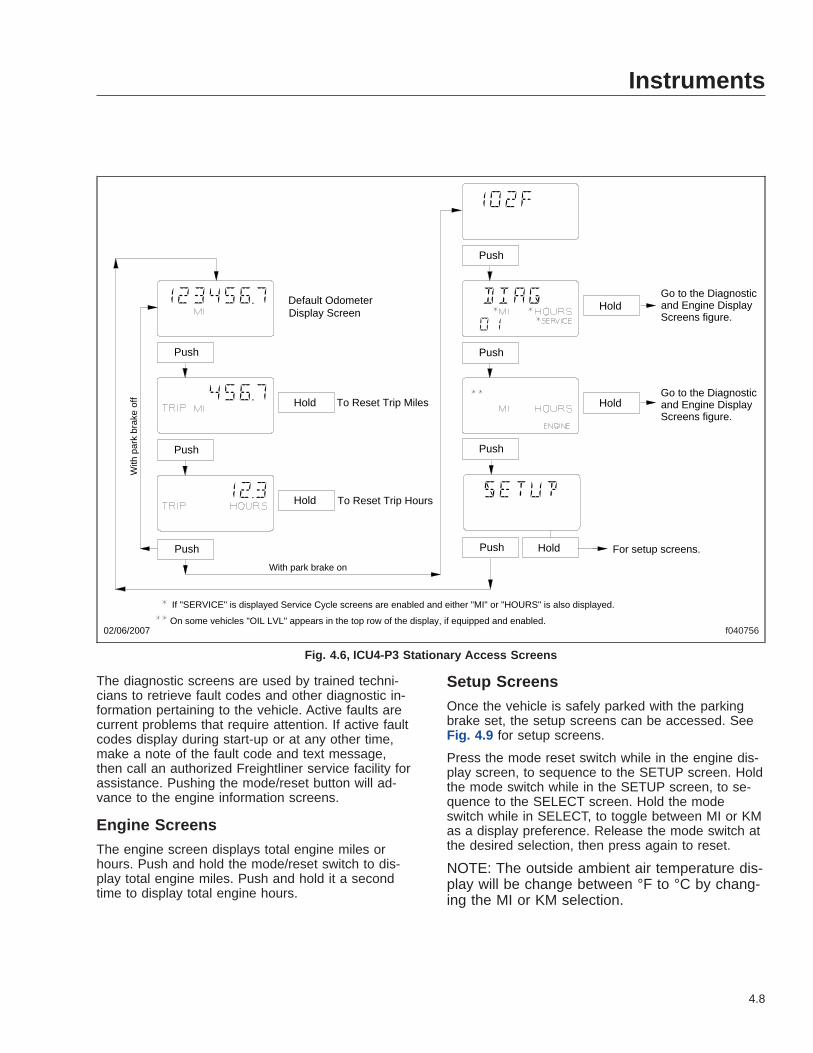
The diagnostic screens are used by trained techni-cians to retrieve fault codes and other diagnostic in-formation pertaining to the vehicle. Active faults arecurrent problems that require attention. If active faultcodes display during start-up or at any other time,make a note of the fault code and text message,then call an authorized Freightliner service facility forassistance. Pushing the mode/reset button will ad-vance to the engine information screens.
Engine ScreensThe engine screen displays total engine miles orhours. Push and hold the mode/reset switch to dis-play total engine miles. Push and hold it a secondtime to display total engine hours.
Setup ScreensOnce the vehicle is safely parked with the parkingbrake set, the setup screens can be accessed. SeeFig. 4.9 for setup screens.
Press the mode reset switch while in the engine dis-play screen, to sequence to the SETUP screen. Holdthe mode switch while in the SETUP screen, to se-quence to the SELECT screen. Hold the modeswitch while in SELECT, to toggle between MI or KMas a display preference. Release the mode switch atthe desired selection, then press again to reset.
NOTE: The outside ambient air temperature dis-play will be change between °F to °C by chang-ing the MI or KM selection.
f040756
Push
With
par
k br
ake
off
Go to the Diagnostic and Engine Display Screens figure.
Hold
If "SERVICE" is displayed Service Cycle screens are enabled and either "MI" or "HOURS" is also displayed.
On some vehicles "OIL LVL" appears in the top row of the display, if equipped and enabled.
Default OdometerDisplay Screen
To Reset Trip Miles
To Reset Trip Hours
Hold
Hold
Hold
Push
Push
Push
Push
Push
Hold For setup screens.
Go to the Diagnostic and Engine Display Screens figure.
With park brake on
Push
02/06/2007
Fig. 4.6, ICU4-P3 Stationary Access Screens
Instruments
4.8
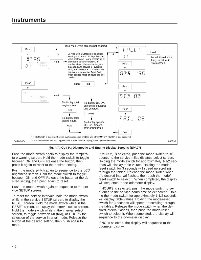
Push the mode switch again to display the tempera-ture warning screen. Hold the mode switch to togglebetween ON and OFF. Release the button, thenpress it again to reset to the desired setting.
Push the mode switch again to sequence to the LCDbrightness screen. Hold the mode switch to togglebetween ON and OFF. Release the button at the de-sired setting, then push again to reset.
Push the mode switch again to sequence to the ser-vice SETUP screen.
To reset the service intervals, hold the mode switchwhile in the service SETUP screen, to display theRESET screen. Hold the mode switch while in theRESET screen, to display the interval select screen.Hold the mode switch while in the interval selectscreen, to toggle between MI (KM), or HOURS forselection of the service interval mode. Release thebutton at the desired setting, then push again toreset.
If MI (KM) is selected, push the mode switch to se-quence to the service miles distance select screen.Holding the mode switch for approximately 1-1/2 sec-onds will display table values. Holding the mode/reset switch for 3 seconds will speed up scrollingthrough the tables. Release the mode switch whenthe desired interval flashes, then push the mode/reset switch to select it. When completed, the displaywill sequence to the odometer display.
If HOURS is selected, push the mode switch to se-quence to the service hours time select screen. Hold-ing the mode switch for approximately 1-1/2 secondswill display table values. Holding the mode/resetswitch for 3 seconds will speed up scrolling throughthe tables. Release the mode switch when the de-sired interval flashes, then push the mode/resetswitch to select it. When completed, the display willsequence to the odometer display.
If NO is selected, the display will sequence to theodometer display.
To display totalengine miles.
To display tolalengine hours.
To display OIL LVLscreens (if equippedand enabled).
To display specific OIL LVL amountover or under full.
For additional faults,if any, or return toDIAG screen.
04/28/2004 f040695
Push
Hold
Push
Push
Push
Hold
Hold
Hold
Push
HoldHold
Hold
Push
Then
If "SERVICE" is displayed Service Cycle screens are enabled and either "MI" or "HOURS" is also displayed.
On some vehicles "OIL LVL" appears in the top row of the display, if equipped and enabled.
Service Cycle Screens (if enabled): Holding the button displays Service Miles or Service Hours, remaining or exceeded, to service target. If numbers flash, the service target is exceeded and service is overdue. Also, the "SERVICE" screen will be displayed as an active Fault Code when service miles or hours are ex−ceeded.
If Service Cycle screens not enabled
Or
Fig. 4.7, ICU4-P3 Diagnostic and Engine Display Screens (EPA07)
Instruments
4.9
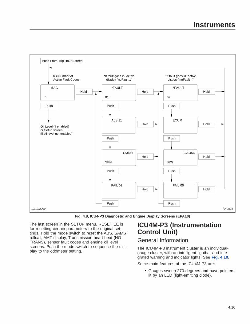
The last screen in the SETUP menu, RESET EE isfor resetting certain parameters to the original set-tings. Hold the mode switch to reset the ABS, SAMSrollcall, AMT display, Transmission heart beat (NOTRANS), sensor fault codes and engine oil levelscreens. Push the mode switch to sequence the dis-play to the odometer setting.
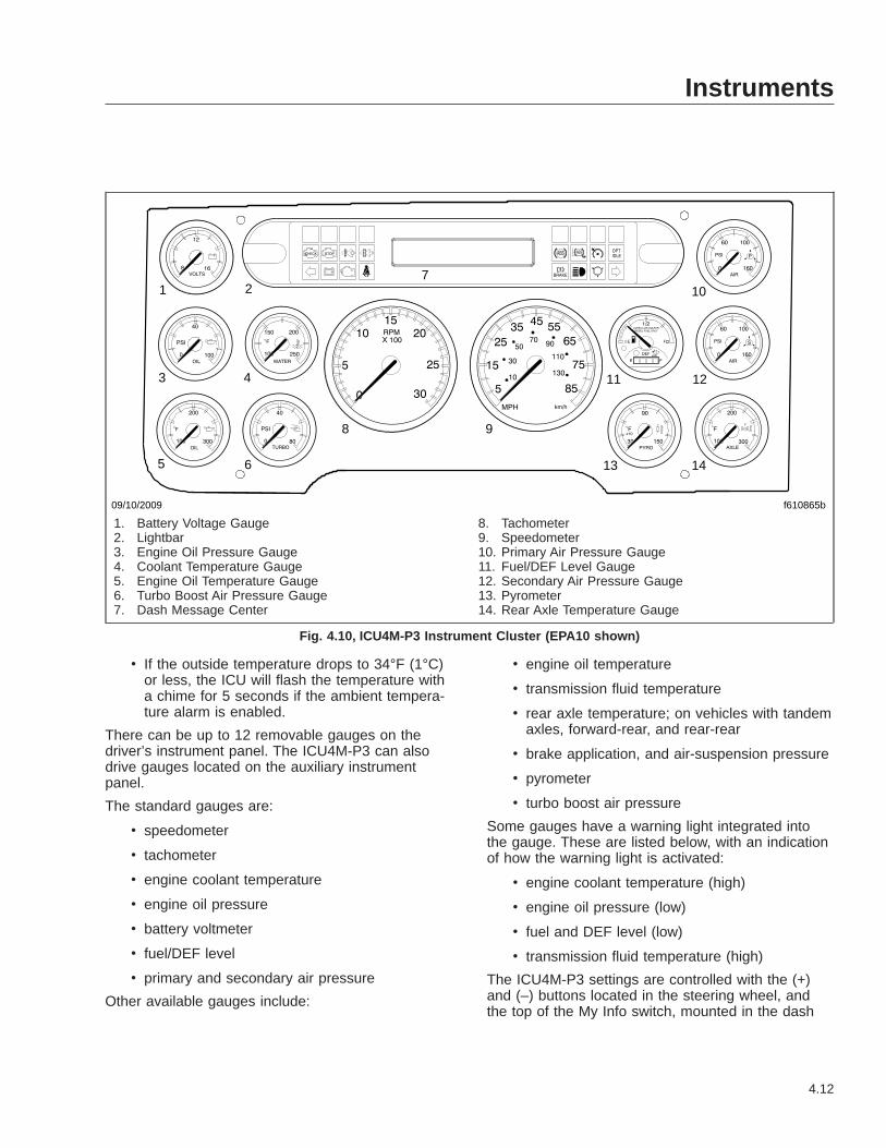
ICU4M-P3 (InstrumentationControl Unit)General InformationThe ICU4M-P3 instrument cluster is an individual-gauge cluster, with an intelligent lightbar and inte-grated warning and indicator lights. See Fig. 4.10 .
Some main features of the ICU4M-P3 are:
• Gauges sweep 270 degrees and have pointerslit by an LED (light-emitting diode).
f04080210/19/2009
Push From Trip Hour Screen
Hold
Push
Hold
Push
Hold
Push
n = Number ofActive Fault Codes
dlAG
n
*FAULT
01
*If fault goes in−activedisplay "noFault 1"
*FAULT
nn
*If fault goes in−activedisplay "noFault n"
Oil Level (if enabled)or Setup screen(if oil level not enabled)
Hold HoldAbS 11 ECU 0
Push Push
Hold Hold123456
Push Push
Hold HoldFAIL 03 FAIL 00
Push Push
SPN SPN
123456
Fig. 4.8, ICU4-P3 Diagnostic and Engine Display Screens (EPA10)
Instruments
4.10
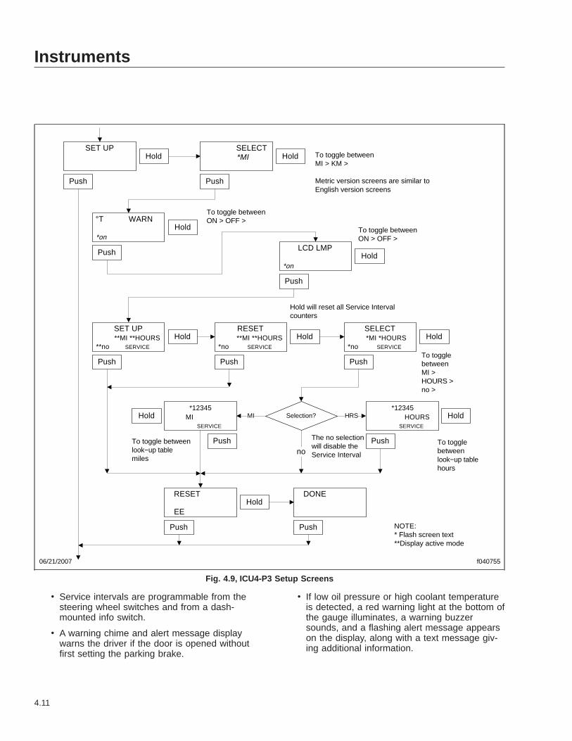
• Service intervals are programmable from thesteering wheel switches and from a dash-mounted info switch.
• A warning chime and alert message displaywarns the driver if the door is opened withoutfirst setting the parking brake.
• If low oil pressure or high coolant temperatureis detected, a red warning light at the bottom ofthe gauge illuminates, a warning buzzersounds, and a flashing alert message appearson the display, along with a text message giv-ing additional information.
Selection?
To toggle betweenlook−up tablehours
To toggle betweenlook−up tablemiles
To toggle betweenMI > HOURS > no >
NOTE:* Flash screen text**Display active mode
The no selection will disable the Service Interval
Hold will reset all Service Interval counters
Metric version screens are similar to English version screens
To toggle betweenMI > KM >
To toggle betweenON > OFF >
Push
To toggle betweenON > OFF >
HRSMI
no
Push
PushPush
Push Push Push
Push
Push
PushPush
Hold
Hold
Hold
Hold
Hold Hold Hold
HoldHold
Hold
SET UP SELECT*MI
SET UP
WARN°T
*on
LCD LMP
*on
**MI **HOURS**no
RESET**MI **HOURS
*no
SELECT*MI *HOURS
*noSERVICE SERVICE SERVICE
*12345MI
SERVICE
*12345HOURS
SERVICE
RESET
EE
DONE
f04075506/21/2007
Fig. 4.9, ICU4-P3 Setup Screens
Instruments
4.11
• If the outside temperature drops to 34°F (1°C)or less, the ICU will flash the temperature witha chime for 5 seconds if the ambient tempera-ture alarm is enabled.
There can be up to 12 removable gauges on thedriver’s instrument panel. The ICU4M-P3 can alsodrive gauges located on the auxiliary instrumentpanel.
The standard gauges are:
• speedometer
• tachometer
• engine coolant temperature
• engine oil pressure
• battery voltmeter
• fuel/DEF level
• primary and secondary air pressure
Other available gauges include:
• engine oil temperature
• transmission fluid temperature
• rear axle temperature; on vehicles with tandemaxles, forward-rear, and rear-rear
• brake application, and air-suspension pressure
• pyrometer
• turbo boost air pressure
Some gauges have a warning light integrated intothe gauge. These are listed below, with an indicationof how the warning light is activated:
• engine coolant temperature (high)
• engine oil pressure (low)
• fuel and DEF level (low)
• transmission fluid temperature (high)
The ICU4M-P3 settings are controlled with the (+)and (–) buttons located in the steering wheel, andthe top of the My Info switch, mounted in the dash
f610865b
1
3 4
5 6
7
8 9
10
11 12
13 14
2
09/10/2009
1. Battery Voltage Gauge2. Lightbar3. Engine Oil Pressure Gauge4. Coolant Temperature Gauge5. Engine Oil Temperature Gauge6. Turbo Boost Air Pressure Gauge7. Dash Message Center
8. Tachometer9. Speedometer10. Primary Air Pressure Gauge11. Fuel/DEF Level Gauge12. Secondary Air Pressure Gauge13. Pyrometer14. Rear Axle Temperature Gauge
Fig. 4.10, ICU4M-P3 Instrument Cluster (EPA10 shown)
Instruments
4.12
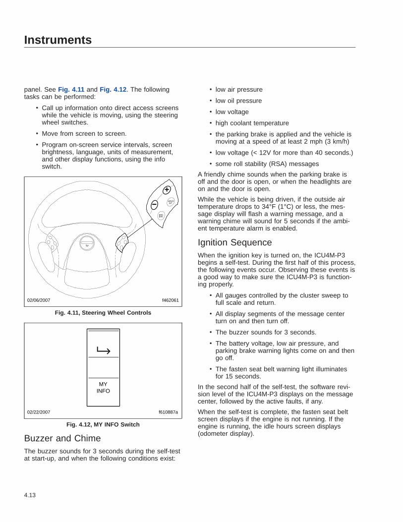
panel. See Fig. 4.11 and Fig. 4.12 . The followingtasks can be performed:
• Call up information onto direct access screenswhile the vehicle is moving, using the steeringwheel switches.
• Move from screen to screen.
• Program on-screen service intervals, screenbrightness, language, units of measurement,and other display functions, using the infoswitch.
Buzzer and ChimeThe buzzer sounds for 3 seconds during the self-testat start-up, and when the following conditions exist:
• low air pressure
• low oil pressure
• low voltage
• high coolant temperature
• the parking brake is applied and the vehicle ismoving at a speed of at least 2 mph (3 km/h)
• low voltage (< 12V for more than 40 seconds.)
• some roll stability (RSA) messages
A friendly chime sounds when the parking brake isoff and the door is open, or when the headlights areon and the door is open.
While the vehicle is being driven, if the outside airtemperature drops to 34°F (1°C) or less, the mes-sage display will flash a warning message, and awarning chime will sound for 5 seconds if the ambi-ent temperature alarm is enabled.
Ignition SequenceWhen the ignition key is turned on, the ICU4M-P3begins a self-test. During the first half of this process,the following events occur. Observing these events isa good way to make sure the ICU4M-P3 is function-ing properly.
• All gauges controlled by the cluster sweep tofull scale and return.
• All display segments of the message centerturn on and then turn off.
• The buzzer sounds for 3 seconds.
• The battery voltage, low air pressure, andparking brake warning lights come on and thengo off.
• The fasten seat belt warning light illuminatesfor 15 seconds.
In the second half of the self-test, the software revi-sion level of the ICU4M-P3 displays on the messagecenter, followed by the active faults, if any.
When the self-test is complete, the fasten seat beltscreen displays if the engine is not running. If theengine is running, the idle hours screen displays(odometer display).
MRKRINT
ENGBRK
−
+
02/06/2007 f462061
Fig. 4.11, Steering Wheel Controls
02/22/2007
MYINFO
f610887a
Fig. 4.12, MY INFO Switch
Instruments
4.13
Alert MessagesWith the parking brake released, only the odometerand alerts messages can be displayed. Park the ve-hicle and set the parking brake to display additionalscreen functions.
The dash message center displays alertss when cer-tain conditions occur. They appear when the parkingbrake is off, and override the regular screen display.They are warnings, cautions, or other messages thatrequire the driver’s attention, but not all of them arecritical to the operation of the vehicle. Warning mes-sages always display at full brightness.
More important messages take priority over less im-portant messages. The order of importance, or prior-ity, is:
1. parking brake on (with the vehicle moving)
2. parking brake off (with door open)
3. low oil pressure, high coolant temperature
4. hard brake warnings (if equipped with RSA)
5. low voltage
6. Caution 34°F (1°C) (or less); road may be icy
7. turn signal on
8. incoming instant or Qualcomm messages
9. service warnings
10. no datalink activity
"Incoming Message" AlertOn vehicles with an onboard Qualcomm communica-tions system, this screen activates whenever a mes-sage is received. "Incoming Message" appears onthe message display screen.
NOTE: The "Incoming Message" screen alsodisplays during the ignition sequence if a mes-sage is available.
This message displays for a preset time period andthen disappears. It returns after the preset intervaluntil it is dismissed by pressing the +, –, or the MYINFO switch.
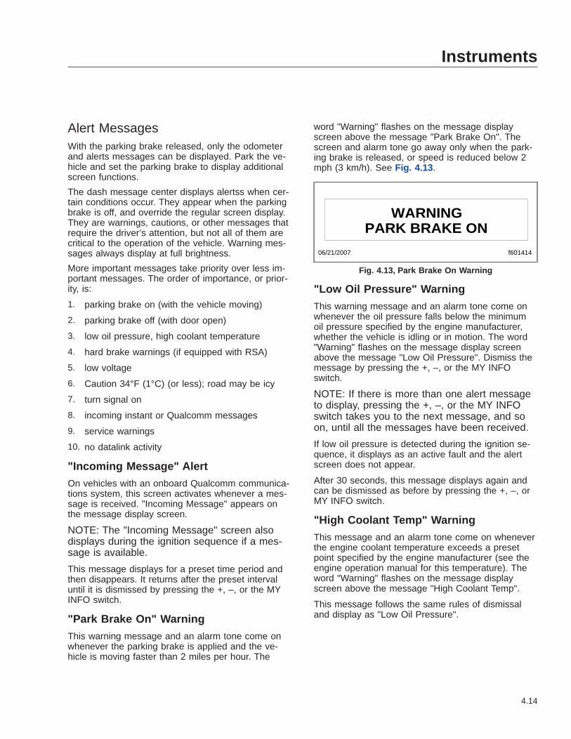
"Park Brake On" WarningThis warning message and an alarm tone come onwhenever the parking brake is applied and the ve-hicle is moving faster than 2 miles per hour. The
word "Warning" flashes on the message displayscreen above the message "Park Brake On". Thescreen and alarm tone go away only when the park-ing brake is released, or speed is reduced below 2mph (3 km/h). See Fig. 4.13 .
"Low Oil Pressure" WarningThis warning message and an alarm tone come onwhenever the oil pressure falls below the minimumoil pressure specified by the engine manufacturer,whether the vehicle is idling or in motion. The word"Warning" flashes on the message display screenabove the message "Low Oil Pressure". Dismiss themessage by pressing the +, –, or the MY INFOswitch.
NOTE: If there is more than one alert messageto display, pressing the +, –, or the MY INFOswitch takes you to the next message, and soon, until all the messages have been received.
If low oil pressure is detected during the ignition se-quence, it displays as an active fault and the alertscreen does not appear.
After 30 seconds, this message displays again andcan be dismissed as before by pressing the +, –, orMY INFO switch.
"High Coolant Temp" WarningThis message and an alarm tone come on wheneverthe engine coolant temperature exceeds a presetpoint specified by the engine manufacturer (see theengine operation manual for this temperature). Theword "Warning" flashes on the message displayscreen above the message "High Coolant Temp".
This message follows the same rules of dismissaland display as "Low Oil Pressure".
f601414
WARNINGPARK BRAKE ON
06/21/2007
Fig. 4.13, Park Brake On Warning
Instruments
4.14
"Low Voltage" WarningOn some vehicles, this message and an alarm tonecome on whenever a low voltage condition is de-tected by the instrumentation control unit. The word"Warning" flashes on the message display screenabove the message "Low Voltage".
"Turn Signal On" WarningThis warning message and buzzer come on when-ever the turn signal remains on for 4 minutes, or 5miles of travel. The word "Warning" flashes on thedisplay screen above the message "Turn Signal On",and the buzzer sounds.
To dismiss this message, either turn off the turn sig-nal, or press the +, –, or MY INFO switch.
"Air Temperature" WarningWhen the outside ambient air temperature drops to34°F (1°C) or less, the ICU will display a warningtext at 1 second intervals for 5 seconds, and afriendly chime will sound. The driver must acknowl-edge the warning by pressing the steering wheelswitch, or the Quick Info switch. The chime will notsound again unless the temperature cycles above37°F (4°C) and back to 34°F (1°C) or less. Thiswarning only occurs while the ignition is on and theparking brake off. The outside ambient air tempera-ture will display in degrees Fahrenheit if MI is se-lected in the setup screens, or degrees Celsius if KMis selected.
NOTE: The ambient air temperature warning isin the disabled state when the vehicle isshipped from the factory. It must be enabled inthe ICU setup screen.
Service WarningsService warning screens display during the ignitionsequence and indicate that a service interval hasbeen reached or exceeded and maintenance is re-quired. The messages may indicate the number ofmiles (KM) or hours until the next service or, oncepassed, the number of miles (KM) or hours ago thatmaintenance should have been performed. The mes-sages read "X Miles (KM) To Next Service", "X HoursTo Next Service", "Service Was Due X Mi (KM) Ago",and "Service Was Due X Hr Ago". The letter X repre-sents the number of miles (KM) or hours pro-grammed.
"No Datalink Activity" Alert (EPA07 only)The "No Datalink Activity" screen comes on when-ever the datalink is not receiving data.
If the condition persists, take the vehicle in for ser-vice as soon as possible to discover the cause of theproblem.
Automated Manual TransmissionsDisplayThe ICU4M-P3 can display current gear informationfor vehicles with automated manual transmissions(AMT). The last 3 digits at the far right on the lowerline are reserved for this information.
If there is a recommendation to shift, one digit dis-plays an arrow, either up or down depending on theshift direction. The other two digits display the cur-rent gear.
On vehicles with conventional manual or automatictransmissions, these 3 digits do not display. For moreinformation about specific models of automatedmanual transmissions, see Chapter 15 .
Favorite ScreenThe driver can access a preset screen using the MYINFO switch. Holding down the bottom of the MYINFO switch for 1.2 seconds will set the currentscreen as the favorite screen. A chirp will sound toverify the screen has been set. Only screens thatcan be accessed with the parking brake off, can beselected as the favorite screen.
The favorite screen can be called up by pressing thebottom of the MY INFO switch. The favorite screencan be accessed with the parking brake off or on.There is no time-out for this screen. The screen canbe acknowledged with any button except the MYINFO, and it will return to the previous screen.
Direct Access ScreensThese are the screens that can be reached when theparking brake is not set. The vehicle can be station-ary or moving to reach these screens. Use the steer-ing wheel buttons to scroll through the main menus.
See Fig. 4.14 for the main stationary and direct ac-cess screens for EPA07.
See Fig. 4.15 for the main stationary and direct ac-cess screens for EPA10.
Instruments
4.15
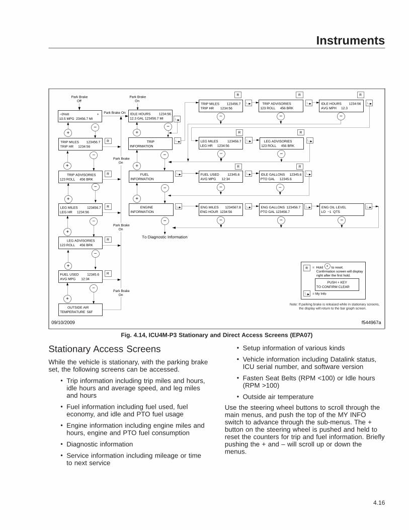
Stationary Access ScreensWhile the vehicle is stationary, with the parking brakeset, the following screens can be accessed.
• Trip information including trip miles and hours,idle hours and average speed, and leg milesand hours
• Fuel information including fuel used, fueleconomy, and idle and PTO fuel usage
• Engine information including engine miles andhours, engine and PTO fuel consumption
• Diagnostic information
• Service information including mileage or timeto next service
• Setup information of various kinds
• Vehicle information including Datalink status,ICU serial number, and software version
• Fasten Seat Belts (RPM <100) or Idle hours(RPM >100)
• Outside air temperature
Use the steering wheel buttons to scroll through themain menus, and push the top of the MY INFOswitch to advance through the sub-menus. The +button on the steering wheel is pushed and held toreset the counters for trip and fuel information. Brieflypushing the + and – will scroll up or down themenus.
Note: If parking brake is released while in stationary screens,the display will return to the bar graph screen.
+
Park BrakeOff
Park BrakeOn
Park Brake On IDLE HOURS 1234:5612.3 GAL 123456.7 MI
PUSH + KEYTO CONFIRM CLEAR
= My Info
= Hold to reset.Confirmation screen will display right after the first hold.
R
R
R
R
R
R
R
R R
R
R R R
+
+
+
+
+
+ +
+
+
−
−
−
− −
−
− −
−
− −
−−
−
−−
− − −
−0%III +10.5 MPG 23456.7 MI
TRIPINFORMATION
TRIP MILES 123456.7TRIP HR 1234:56
Park BrakeOn
Park BrakeOn
Park BrakeOn
TRIP ADVISORIES123 ROLL 456 BRK
FUELINFORMATION
LEG MILES 123456.7LEG HR 1234:56
ENGINEINFORMATION
LEG ADVISORIES123 ROLL 456 BRK
FUEL USED 12345.6AVG MPG 12:34
OUTSIDE AIRTEMPERATURE 56F
TRIP MILES 123456.7TRIP HR 1234:56
TRIP ADVISORIES123 ROLL 456 BRK
IDLE HOURS 1234:56AVG MPH 12.3
LEG MILES 123456.7LEG HR 1234:56
LEG ADVISORIES123 ROLL 456 BRK
FUEL USED 12345.6AVG MPG 12:34
IDLE GALLONS 12345.6PTO GAL 12345.6
ENG MILES 1234567.8ENG HOUR 1234:56
ENG GALLONS 123456.7PTO GAL 123456.7
ENG OIL LEVELLO −1 QTS
f544967a
−
To Diagnostic Information
09/10/2009
Fig. 4.14, ICU4M-P3 Stationary and Direct Access Screens (EPA07)
Instruments
4.16
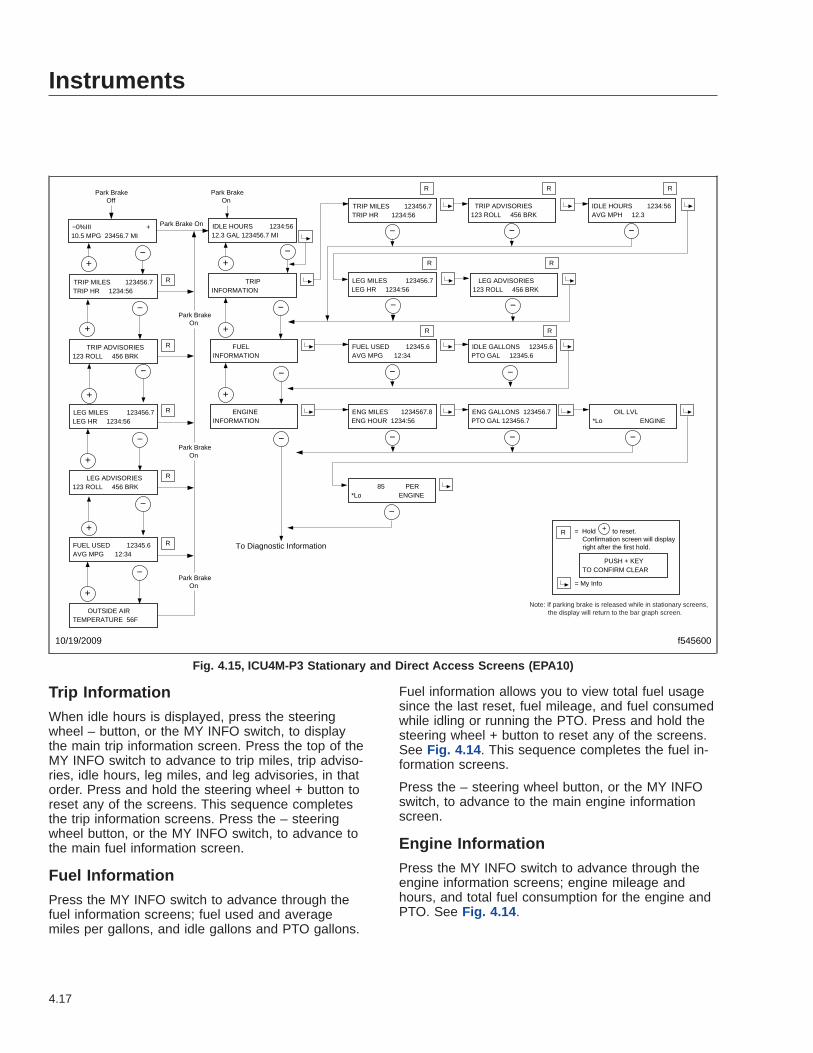
Trip InformationWhen idle hours is displayed, press the steeringwheel – button, or the MY INFO switch, to displaythe main trip information screen. Press the top of theMY INFO switch to advance to trip miles, trip adviso-ries, idle hours, leg miles, and leg advisories, in thatorder. Press and hold the steering wheel + button toreset any of the screens. This sequence completesthe trip information screens. Press the – steeringwheel button, or the MY INFO switch, to advance tothe main fuel information screen.
Fuel InformationPress the MY INFO switch to advance through thefuel information screens; fuel used and averagemiles per gallons, and idle gallons and PTO gallons.
Fuel information allows you to view total fuel usagesince the last reset, fuel mileage, and fuel consumedwhile idling or running the PTO. Press and hold thesteering wheel + button to reset any of the screens.See Fig. 4.14 . This sequence completes the fuel in-formation screens.
Press the – steering wheel button, or the MY INFOswitch, to advance to the main engine informationscreen.
Engine InformationPress the MY INFO switch to advance through theengine information screens; engine mileage andhours, and total fuel consumption for the engine andPTO. See Fig. 4.14 .
Note: If parking brake is released while in stationary screens,the display will return to the bar graph screen.
+
Park BrakeOff
Park BrakeOn
Park Brake On IDLE HOURS 1234:5612.3 GAL 123456.7 MI
PUSH + KEYTO CONFIRM CLEAR
= My Info
= Hold to reset.Confirmation screen will display right after the first hold.
R
R
R
R
R
R
R
R R
R
R R R
+
+
+
+
+
+ +
+
+
−
−
−
− −
−
− −
−
− −
−−
−
−−
− − −
−0%III +10.5 MPG 23456.7 MI
TRIPINFORMATION
TRIP MILES 123456.7TRIP HR 1234:56
Park BrakeOn
Park BrakeOn
Park BrakeOn
TRIP ADVISORIES123 ROLL 456 BRK
FUELINFORMATION
LEG MILES 123456.7LEG HR 1234:56
ENGINEINFORMATION
LEG ADVISORIES123 ROLL 456 BRK
FUEL USED 12345.6AVG MPG 12:34
OUTSIDE AIRTEMPERATURE 56F
TRIP MILES 123456.7TRIP HR 1234:56
TRIP ADVISORIES123 ROLL 456 BRK
IDLE HOURS 1234:56AVG MPH 12.3
LEG MILES 123456.7LEG HR 1234:56
LEG ADVISORIES123 ROLL 456 BRK
FUEL USED 12345.6AVG MPG 12:34
IDLE GALLONS 12345.6PTO GAL 12345.6
ENG MILES 1234567.8ENG HOUR 1234:56
ENG GALLONS 123456.7PTO GAL 123456.7
OIL LVL*Lo
f545600
−
To Diagnostic Information
10/19/2009
−
85
ENGINE
PER*Lo ENGINE
Fig. 4.15, ICU4M-P3 Stationary and Direct Access Screens (EPA10)
Instruments
4.17
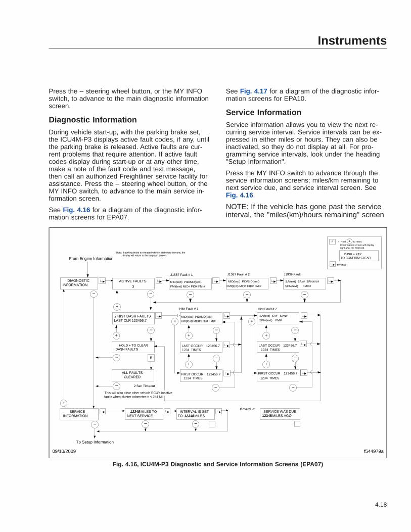
Press the – steering wheel button, or the MY INFOswitch, to advance to the main diagnostic informationscreen.
Diagnostic InformationDuring vehicle start-up, with the parking brake set,the ICU4M-P3 displays active fault codes, if any, untilthe parking brake is released. Active faults are cur-rent problems that require attention. If active faultcodes display during start-up or at any other time,make a note of the fault code and text message,then call an authorized Freightliner service facility forassistance. Press the – steering wheel button, or theMY INFO switch, to advance to the main service in-formation screen.
See Fig. 4.16 for a diagram of the diagnostic infor-mation screens for EPA07.
See Fig. 4.17 for a diagram of the diagnostic infor-mation screens for EPA10.
Service InformationService information allows you to view the next re-curring service interval. Service intervals can be ex-pressed in either miles or hours. They can also beinactivated, so they do not display at all. For pro-gramming service intervals, look under the heading"Setup Information".
Press the MY INFO switch to advance through theservice information screens; miles/km remaining tonext service due, and service interval screen. SeeFig. 4.16 .
NOTE: If the vehicle has gone past the serviceinterval, the "miles(km)/hours remaining" screen
MID(text) PID/SID(text)
FMI(text) MID# PID# FMI#
DIAGNOSTICINFORMATION
ACTIVE FAULTS
3
2 HIST DASH FAULTSLAST CLR 123456.7
LAST OCCUR 123456.71234 TIMES
J1587 Fault # 1
Hist Fault # 1 Hist Fault # 2
+
MID(text) PID/SID(text)
FMI(text) MID# PID# FMI#
MID(text) PID/SID(text)
FMI(text) MID# PID# FMI#
SA(text) SA# SPN#
SPN(text) FMI#
FIRST OCCUR 123456.71234 TIMES
LAST OCCUR 123456.71234 TIMES
FIRST OCCUR 123456.71234 TIMES
faults when cluster odometer is < 254 MI.
MILES TONEXT SERVICE
INTERVAL IS SETTO MILES
HOLD + TO CLEARDASH FAULTS
ALL FAULTSCLEARED
R
+
SERVICEINFORMATION
SERVICE WAS DUEMILES AGO
SA(text) SA## SPN####
SPN(text) FMI##
J1587 Fault # 2 J1939 Fault
2 Sec Timeout
This will also clear other vehicle ECU’s inactive
If overdue:
R = Hold to reset.
PUSH + KEYTO CONFIRM CLEAR
Confirmation screen will displayright after the first hold.
−−−
− −
−−+
++−−
+
−+
−
−
+
−− − − −
+
+
1234512345 12345
Note: If parking brake is released while in stationary screens, thedisplay will return to the bargraph screen.
f544979a
To Setup Information
From Engine Information
09/10/2009
My Info
Fig. 4.16, ICU4M-P3 Diagnostic and Service Information Screens (EPA07)
Instruments
4.18
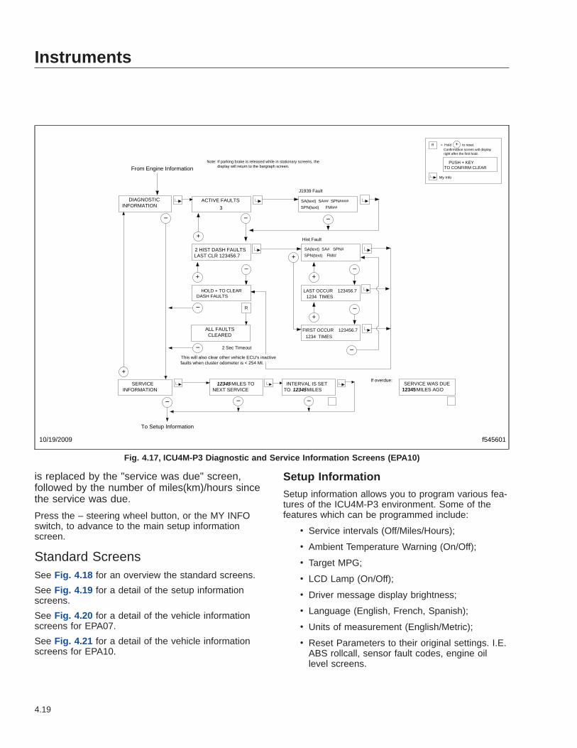
is replaced by the "service was due" screen,followed by the number of miles(km)/hours sincethe service was due.
Press the – steering wheel button, or the MY INFOswitch, to advance to the main setup informationscreen.
Standard ScreensSee Fig. 4.18 for an overview the standard screens.
See Fig. 4.19 for a detail of the setup informationscreens.
See Fig. 4.20 for a detail of the vehicle informationscreens for EPA07.
See Fig. 4.21 for a detail of the vehicle informationscreens for EPA10.
Setup InformationSetup information allows you to program various fea-tures of the ICU4M-P3 environment. Some of thefeatures which can be programmed include:
• Service intervals (Off/Miles/Hours);
• Ambient Temperature Warning (On/Off);
• Target MPG;
• LCD Lamp (On/Off);
• Driver message display brightness;
• Language (English, French, Spanish);
• Units of measurement (English/Metric);
• Reset Parameters to their original settings. I.E.ABS rollcall, sensor fault codes, engine oillevel screens.
DIAGNOSTICINFORMATION
ACTIVE FAULTS
3
2 HIST DASH FAULTSLAST CLR 123456.7
Hist Fault
+
SA(text) SA# SPN#
SPN(text) FMI#
LAST OCCUR 123456.71234 TIMES
FIRST OCCUR 123456.71234 TIMES
faults when cluster odometer is < 254 MI.
MILES TONEXT SERVICE
INTERVAL IS SETTO MILES
HOLD + TO CLEARDASH FAULTS
ALL FAULTSCLEARED
R
+
SERVICEINFORMATION
SERVICE WAS DUEMILES AGO
SA(text) SA## SPN####
SPN(text) FMI##
J1939 Fault
2 Sec Timeout
This will also clear other vehicle ECU’s inactive
If overdue:
R = Hold to reset.
PUSH + KEYTO CONFIRM CLEAR
Confirmation screen will displayright after the first hold.
−−−
−
−
+−−
+
−
−
+
−− −
+
+
1234512345 12345
Note: If parking brake is released while in stationary screens, thedisplay will return to the bargraph screen.
f545601
To Setup Information
From Engine Information
10/19/2009
My Info
Fig. 4.17, ICU4M-P3 Diagnostic and Service Information Screens (EPA10)
Instruments
4.19
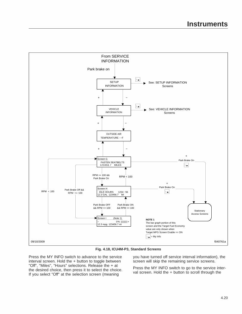
Press the MY INFO switch to advance to the serviceinterval screen. Hold the + button to toggle between"Off", "Miles", "Hours" selections. Release the + atthe desired choice, then press it to select the choice.If you select "Off" at the selection screen (meaning
you have turned off service interval information), thescreen will skip the remaining service screens.
Press the MY INFO switch to go to the service inter-val screen. Hold the + button to scroll through the
f040761a
Screen G
FASTEN SEATBELTS123456.7 MILES
Screen H
IDLE HOURS 1234 : 5612.3 GAL 123456.7 MI
Screen I (Note 1)
− 0% || | | | | | | +12.3 mpg 123456.7 mi
RPM >= 100 &&Park Brake On
RPM < 100
Park Brake OFF&& RPM >= 100
RPM < 100Park Brake Off &&
RPM >= 100
Park Brake On
Park Brake On
StationaryAccess Screens
NOTE 1The bar graph portion of thisscreen and the Target Fuel Economyvalue are only shown whenTarget MPG Screen Enable == ON
OUTSIDE AIR
TEMPERATURE −−F
−
VEHICLEINFORMATION
SETUPINFORMATION
−+
+
Park brake on
From SERVICEINFORMATION
See: SETUP INFORMATIONScreens
Park Brake ON&& RPM >= 100
−+
See: VEHICLE INFORMATIONScreens
= My Info
09/10/2009
+
+
Fig. 4.18, ICU4M-P3, Standard Screens
Instruments
4.20
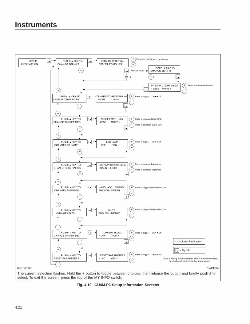
09/10/2009
SETUPINFORMATION
+
−
+
−
+
−
+
−
+
−
+
−
+
−
+
−
+
−
+
−
+
+
+
+
+
+
+
+
−
−
−
−
−
−
−
−
−
+
PUSH KEY TO
Note: If parking brake is released while in stationary screens,the display will return to the bar graph screen.
* = Indicates flashing text
= My Info
Press to toggle between selections
Miles or Hours
Press to set service interval
Press to toggle On Off
Press to toggle On Off
Press to toggle On Off
Press to toggle Yes No
Press to increase target MPG
Press to decrease target MPG
Press to increase brightness
Press to decrease brightness
Press to toggle between selections
Press to toggle between selections
Off
SERVICE INTERVAL
PUSH KEY TOCHANGE SERV MI
PUSH KEY TOCHANGE TEMP WARN
PUSH KEY TOCHANGE TARGET MPG
PUSH KEY TO
PUSH KEY TO
PUSH KEY TO
PUSH KEY TO
PUSH KEY TO
PUSH KEY TO
INTERVAL *2000 MILES− LESS MORE +
TEMPERATURE WARNING− OFF * ON +
LCD LAMP− OFF * ON +
TARGET MPG *8.5− LESS MORE +
CHANGE LCD LAMP
CHANGE BRIGHTNESS
CHANGE LANGUAGE
DISPLAY BRIGHTNESS− DARK LIGHT +
LANGUAGE: *ENGLISHFRENCH / SPNISH
CHANGE UNITS
CHANGE DRIVER SEL
RESET PARAMETERS
UNITS*ENGLISH / METRIC
DRIVER SELECT− OFF * ON +
RESET PARAMETERS− *NO YES +
f544963a
OFF/*MILES/HOURS
CHANGE SERVICE
The current selection flashes. Hold the + button to toggle between choices, then release the button and briefly push it toselect. To exit the screen, press the top of the MY INFO switch.
Fig. 4.19, ICU4M-P3 Setup Information Screens
Instruments
4.21
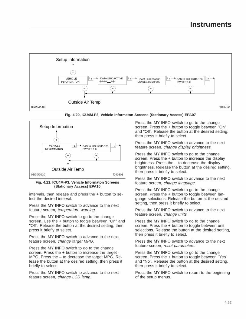
intervals, then release and press the + button to se-lect the desired interval.
Press the MY INFO switch to advance to the nextfeature screen, temperature warning.
Press the MY INFO switch to go to the changescreen. Use the + button to toggle between "On" and"Off". Release the button at the desired setting, thenpress it briefly to select.
Press the MY INFO switch to advance to the nextfeature screen, change target MPG.
Press the MY INFO switch to go to the changescreen. Press the + button to increase the targetMPG. Press the – to decrease the target MPG. Re-lease the button at the desired setting, then press itbriefly to select.
Press the MY INFO switch to advance to the nextfeature screen, change LCD lamp.
Press the MY INFO switch to go to the changescreen. Press the + button to toggle between "On"and "Off". Release the button at the desired setting,then press it briefly to select.
Press the MY INFO switch to advance to the nextfeature screen, change display brightness.
Press the MY INFO switch to go to the changescreen. Press the + button to increase the displaybrightness. Press the – to decrease the displaybrightness. Release the button at the desired setting,then press it briefly to select.
Press the MY INFO switch to advance to the nextfeature screen, change language.
Press the MY INFO switch to go to the changescreen. Press the + button to toggle between lan-guage selections. Release the button at the desiredsetting, then press it briefly to select.
Press the MY INFO switch to advance to the nextfeature screen, change units.
Press the MY INFO switch to go to the changescreen. Press the + button to toggle between unitselections. Release the button at the desired setting,then press it briefly to select.
Press the MY INFO switch to advance to the nextfeature screen, reset parameters.
Press the MY INFO switch to go to the changescreen. Press the + button to toggle between "Yes"and "No". Release the button at the desired setting,then press it briefly to select.
Press the MY INFO switch to return to the beginningof the setup menus.
f04076208/26/2008
+
− − − −
VEHICLEINFORMATION
DATALINK ACTIVE DATA LINK STATUSUSAGE 12% ERR2%
DASH# 123−12345−123SW VER 1.0
Setup Information
Outside Air Temp
Fig. 4.20, ICU4M-P3, Vehicle Informaton Screens (Stationary Access) EPA07
+
− −
VEHICLEINFORMATION
DASH# 123−12345−123SW VER 1.0
Setup Information
Outside Air Temp03/30/2010 f040803
Fig. 4.21, ICU4M-P3, Vehicle Informaton Screens(Stationary Access) EPA10
Instruments
4.22
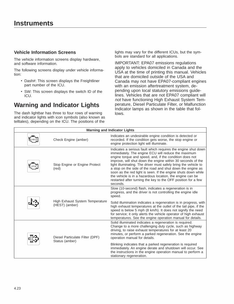
Vehicle Information ScreensThe vehicle information screens display hardware,and software information.
The following screens display under vehicle informa-tion:
• Dash#: This screen displays the Freightlinerpart number of the ICU.
• SW: This screen displays the switch ID of theICU.
Warning and Indicator LightsThe dash lightbar has three to four rows of warningand indicator lights with icon symbols (also known astelltales), depending on the ICU. The positions of the
lights may vary for the different ICUs, but the sym-bols are standard for all applications.
IMPORTANT: EPA07 emissions regulationsapply to vehicles domiciled in Canada and theUSA at the time of printing this manual. Vehiclesthat are domiciled outside of the USA andCanada may not have EPA07-compliant engineswith an emission aftertreatment system, de-pending upon local statutory emissions guide-lines. Vehicles that are not EPA07 compliant willnot have functioning High Exhaust System Tem-perature, Diesel Particulate Filter, or MalfunctionIndicator lamps as shown in the table that fol-lows.
Warning and Indicator Lights
CHECK Check Engine (amber)Indicates an undesirable engine condition is detected orrecorded. If the condition gets worse, the stop engine orengine protection light will illuminate.
STOPStop Engine or Engine Protect(red)
Indicates a serious fault which requires the engine shut downimmediately. The engine ECU will reduce the maximumengine torque and speed, and, if the condition does notimprove, will shut down the engine within 30 seconds of thelight illuminating. The driver must safely bring the vehicle toa stop on the side of the road and shut down the engine assoon as the red light is seen. If the engine shuts down whilethe vehicle is in a hazardous location, the engine can berestarted after turning the key to the OFF position for a fewseconds.
High Exhaust System Temperature(HEST) (amber)
Slow (10-second) flash, indicates a regeneration is inprogress, and the driver is not controlling the engine idlespeed.
Solid illumination indicates a regeneration is in progress, withhigh exhaust temperatures at the outlet of the tail pipe, if thespeed is below 5 mph (8 km/h). It does not signify the needfor service; it only alerts the vehicle operator of high exhausttemperatures. See the engine operation manual for details.
Diesel Particulate Filter (DPF)Status (amber)
Solid illuminated indicates a regeneration is required.Change to a more challenging duty cycle, such as highwaydriving, to raise exhaust temperatures for at least 20minutes, or perform a parked regeneration. See the engineoperation manual for details.
Blinking indicates that a parked regeneration is requiredimmediately. An engine derate and shutdown will occur. Seethe instructions in the engine operation manual to perform astationary regeneration.
Instruments
4.23
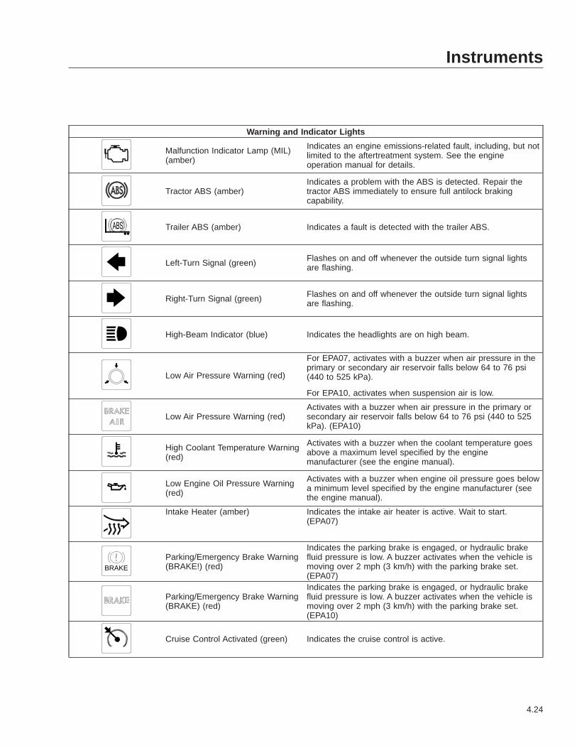
Warning and Indicator Lights
Malfunction Indicator Lamp (MIL)(amber)
Indicates an engine emissions-related fault, including, but notlimited to the aftertreatment system. See the engineoperation manual for details.
Tractor ABS (amber)Indicates a problem with the ABS is detected. Repair thetractor ABS immediately to ensure full antilock brakingcapability.
Trailer ABS (amber) Indicates a fault is detected with the trailer ABS.
Left-Turn Signal (green) Flashes on and off whenever the outside turn signal lightsare flashing.
Right-Turn Signal (green) Flashes on and off whenever the outside turn signal lightsare flashing.
High-Beam Indicator (blue) Indicates the headlights are on high beam.
Low Air Pressure Warning (red)
For EPA07, activates with a buzzer when air pressure in theprimary or secondary air reservoir falls below 64 to 76 psi(440 to 525 kPa).
For EPA10, activates when suspension air is low.
Low Air Pressure Warning (red)Activates with a buzzer when air pressure in the primary orsecondary air reservoir falls below 64 to 76 psi (440 to 525kPa). (EPA10)
High Coolant Temperature Warning(red)
Activates with a buzzer when the coolant temperature goesabove a maximum level specified by the enginemanufacturer (see the engine manual).
Low Engine Oil Pressure Warning(red)
Activates with a buzzer when engine oil pressure goes belowa minimum level specified by the engine manufacturer (seethe engine manual).
Intake Heater (amber) Indicates the intake air heater is active. Wait to start.(EPA07)
BRAKE
Parking/Emergency Brake Warning(BRAKE!) (red)
Indicates the parking brake is engaged, or hydraulic brakefluid pressure is low. A buzzer activates when the vehicle ismoving over 2 mph (3 km/h) with the parking brake set.(EPA07)
Parking/Emergency Brake Warning(BRAKE) (red)
Indicates the parking brake is engaged, or hydraulic brakefluid pressure is low. A buzzer activates when the vehicle ismoving over 2 mph (3 km/h) with the parking brake set.(EPA10)
Cruise Control Activated (green) Indicates the cruise control is active.
Instruments
4.24
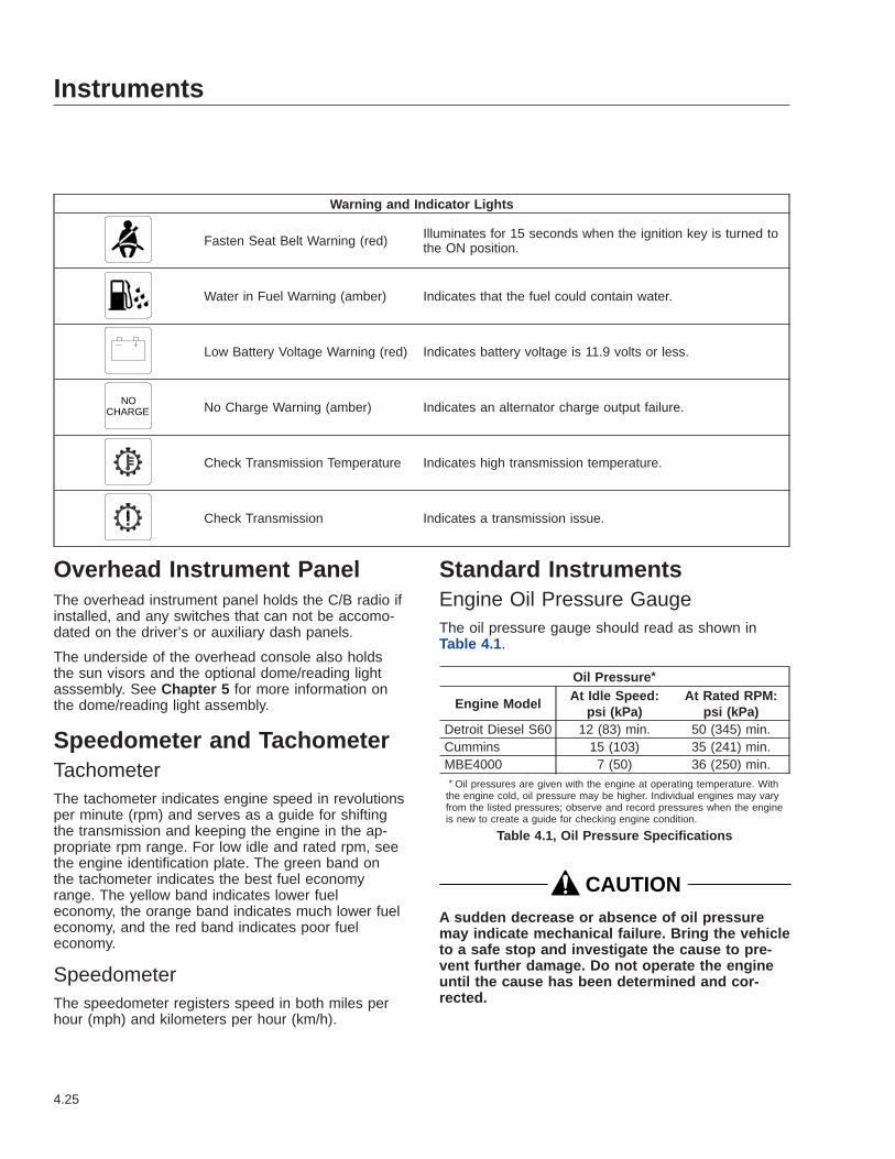
Warning and Indicator Lights
Fasten Seat Belt Warning (red) Illuminates for 15 seconds when the ignition key is turned tothe ON position.
Water in Fuel Warning (amber) Indicates that the fuel could contain water.
Low Battery Voltage Warning (red) Indicates battery voltage is 11.9 volts or less.
NOCHARGE No Charge Warning (amber) Indicates an alternator charge output failure.
Check Transmission Temperature Indicates high transmission temperature.
Check Transmission Indicates a transmission issue.
Overhead Instrument PanelThe overhead instrument panel holds the C/B radio ifinstalled, and any switches that can not be accomo-dated on the driver’s or auxiliary dash panels.
The underside of the overhead console also holdsthe sun visors and the optional dome/reading lightasssembly. See Chapter 5 for more information onthe dome/reading light assembly.
Speedometer and TachometerTachometerThe tachometer indicates engine speed in revolutionsper minute (rpm) and serves as a guide for shiftingthe transmission and keeping the engine in the ap-propriate rpm range. For low idle and rated rpm, seethe engine identification plate. The green band onthe tachometer indicates the best fuel economyrange. The yellow band indicates lower fueleconomy, the orange band indicates much lower fueleconomy, and the red band indicates poor fueleconomy.
SpeedometerThe speedometer registers speed in both miles perhour (mph) and kilometers per hour (km/h).
Standard InstrumentsEngine Oil Pressure GaugeThe oil pressure gauge should read as shown inTable 4.1 .
Oil Pressure *
Engine ModelAt Idle Speed:
psi (kPa)At Rated RPM:
psi (kPa)Detroit Diesel S60 12 (83) min. 50 (345) min.Cummins 15 (103) 35 (241) min.MBE4000 7 (50) 36 (250) min.* Oil pressures are given with the engine at operating temperature. With
the engine cold, oil pressure may be higher. Individual engines may varyfrom the listed pressures; observe and record pressures when the engineis new to create a guide for checking engine condition.
Table 4.1, Oil Pressure Specifications
CAUTIONA sudden decrease or absence of oil pressuremay indicate mechanical failure. Bring the vehicleto a safe stop and investigate the cause to pre-vent further damage. Do not operate the engineuntil the cause has been determined and cor-rected.
Instruments
4.25
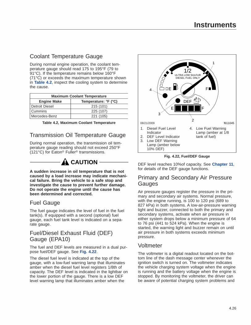
Coolant Temperature GaugeDuring normal engine operation, the coolant tem-perature gauge should read 175 to 195°F (79 to91°C). If the temperature remains below 160°F(71°C) or exceeds the maximum temperature shownin Table 4.2 , inspect the cooling system to determinethe cause.
Maximum Coolant TemperatureEngine Make Temperature: °F (°C)
Detroit Diesel 215 (101)Cummins 225 (107)Mercedes-Benz 221 (105)
Table 4.2, Maximum Coolant Temperature
Transmission Oil Temperature GaugeDuring normal operation, the transmission oil tem-perature gauge reading should not exceed 250°F(121°C) for Eaton® Fuller® transmissions.
CAUTIONA sudden increase in oil temperature that is notcaused by a load increase may indicate mechani-cal failure. Bring the vehicle to a safe stop andinvestigate the cause to prevent further damage.Do not operate the engine until the cause hasbeen determined and corrected.
Fuel GaugeThe fuel gauge indicates the level of fuel in the fueltank(s). If equipped with a second (optional) fuelgauge, each fuel tank level is indicated on a sepa-rate gauge.
Fuel/Diesel Exhaust Fluid (DEF)Gauge (EPA10)The fuel and DEF levels are measured in a dual pur-pose fuel/DEF gauge. See Fig. 4.22 .
The diesel fuel level is indicated at the top of thegauge, with a low-fuel warning lamp that illuminatesamber when the diesel fuel level registers 1/8th ofcapacity. The DEF level is indicated in the lightbar onthe lower portion of the gauge. There is a low DEFlevel warning lamp that illuminates amber when the
DEF level reaches 10%of capacity. See Chapter 11 ,for details of the DEF gauge functions.
Primary and Secondary Air PressureGaugesAir pressure gauges register the pressure in the pri-mary and secondary air systems. Normal pressure,with the engine running, is 100 to 120 psi (689 to827 kPa) in both systems. A low-air-pressure warninglight and buzzer, connected to both the primary andsecondary systems, activate when air pressure ineither system drops below a minimum pressure of 64to 76 psi (441 to 524 kPa). When the engine isstarted, the warning light and buzzer remain on untilair pressure in both systems exceeds minimumpressure.
VoltmeterThe voltmeter is a digital readout located on the bot-tom line of the dash message center whenever theignition switch is turned on. The voltmeter indicatesthe vehicle charging system voltage when the engineis running and the battery voltage when the engine isstopped. By monitoring the voltmeter, the driver canbe aware of potential charging system problems and
08/21/2009
1/2ULTRA LOW SULFURDIESEL FUEL ONLY
E F
DEF
FE
f611045
1
2
3
4
1. Diesel Fuel LevelIndicator
2. DEF Level Indicator3. Low DEF Warning
Lamp (amber below10% DEF)
4. Low Fuel WarningLamp (amber at 1/8tank of fuel)
Fig. 4.22, Fuel/DEF Gauge
Instruments
4.26
have them fixed before the batteries dischargeenough to create starting difficulties.
The voltmeter will normally show approximately 13.7to 14.1 volts when the engine is running. The voltageof a fully charged battery is 12.7 to 12.8 volts whenthe engine is stopped. A completely discharged bat-tery will produce only about 12.0 volts. The voltmeterwill indicate lower voltage as the vehicle is beingstarted or when electrical devices in the vehicle arebeing used.
If the voltmeter shows an undercharged or over-charged condition for an extended period, have thecharging system and batteries checked at a repairfacility.
On a vehicle equipped with a battery isolator system,the voltmeter measures the average voltage of all thebatteries when the engine is running. When the en-gine is stopped, the voltmeter shows only the gel cellbattery voltage and does not indicate the voltage ofthe engine-starting batteries.
CAUTIONGel cell batteries can be damaged if the batteryvoltage is allowed to drop below 12.0 volts or ifthe charging voltage is more than 14.1 volts.Start the engine to recharge the gel cell beforethe battery becomes fully discharged. If an exter-nal charger is needed, disconnect the gel cellbattery and use only an external battery chargerthat has been approved for gel cell batteries.
Optional InstrumentsEngine Oil Temperature GaugeDuring normal operation, the engine oil temperaturegauge should read from 200 to 260°F (93 to 126°C).Under heavy loads, such as when climbing steepgrades, temperatures that exceed the normal oil tem-perature range for a short period are not unusual.
CAUTIONA sudden increase in oil temperature that is notcaused by a load increase may indicate mechani-cal failure. Bring the vehicle to a safe stop andinvestigate the cause to prevent further damage.Do not operate the engine until the cause hasbeen determined and corrected.
Turbocharger Boost Pressure GaugeA turbocharger boost pressure gauge measures thepressure in the intake manifold, in excess of atmos-pheric pressure, being created by the turbocharger.
PyrometerA pyrometer registers the exhaust temperature nearthe turbocharger. Normal exhaust temperatures are700 to 1100°F (370 to 595°C).
Variations in engine load can cause exhaust tem-peratures to rise as high as 1100°F (600°C). If thepyrometer reading shows that exhaust temperatureexceeds normal, reduce fuel to the engine until theexhaust temperature is reduced. Shift to a lower gearif the engine is overloaded.
Forward and Rear Axle OilTemperature GaugesDuring normal operation, forward and rear axle oiltemperature gauges should read between:
• 160 and 220°F (71 and 104°C) for Meritor™
drive axles;
• 180 and 200°F (82 and 93°C) for Dana Spicer®
drive axles.
Under heavy loads, such as when climbing steepgrades, temperatures up to a maximum of 250°F(121°C) are not unusual.
CAUTIONA sudden increase in oil temperature that is notcaused by a load increase may indicate mechani-cal failure. Bring the vehicle to a safe stop andinvestigate the cause to prevent further damage.Do not operate the engine until the cause hasbeen determined and corrected.
Application Air Pressure GaugeAn application air pressure gauge registers the airpressure being used to apply the brakes, and shouldbe used for reference only. The gauge will not regis-ter air pressure until the foot brake pedal is de-pressed or the trailer hand brake is applied.
Instruments
4.27
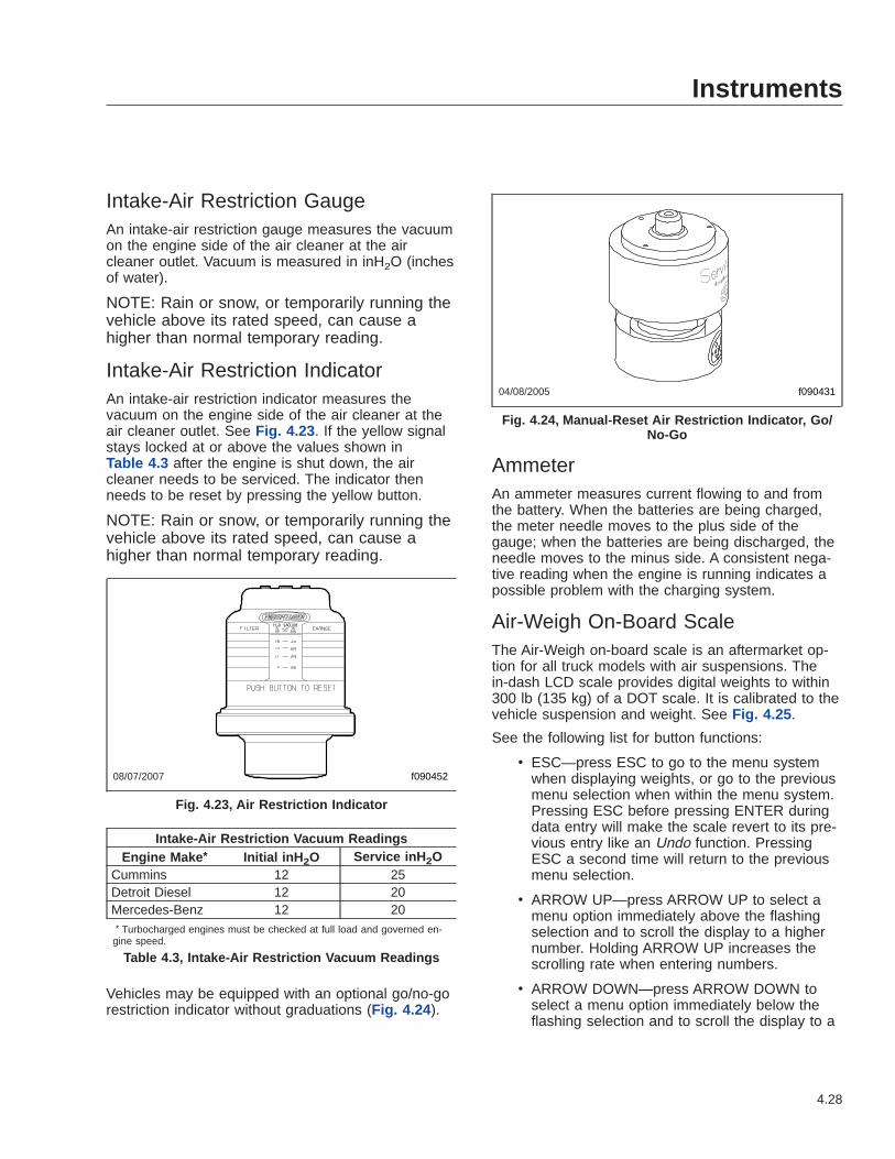
Intake-Air Restriction GaugeAn intake-air restriction gauge measures the vacuumon the engine side of the air cleaner at the aircleaner outlet. Vacuum is measured in inH2O (inchesof water).
NOTE: Rain or snow, or temporarily running thevehicle above its rated speed, can cause ahigher than normal temporary reading.
Intake-Air Restriction IndicatorAn intake-air restriction indicator measures thevacuum on the engine side of the air cleaner at theair cleaner outlet. See Fig. 4.23 . If the yellow signalstays locked at or above the values shown inTable 4.3 after the engine is shut down, the aircleaner needs to be serviced. The indicator thenneeds to be reset by pressing the yellow button.
NOTE: Rain or snow, or temporarily running thevehicle above its rated speed, can cause ahigher than normal temporary reading.
Intake-Air Restriction Vacuum ReadingsEngine Make * Initial inH 2O Service inH 2O
Cummins 12 25Detroit Diesel 12 20Mercedes-Benz 12 20* Turbocharged engines must be checked at full load and governed en-
gine speed.
Table 4.3, Intake-Air Restriction Vacuum Readings
Vehicles may be equipped with an optional go/no-gorestriction indicator without graduations (Fig. 4.24 ).
AmmeterAn ammeter measures current flowing to and fromthe battery. When the batteries are being charged,the meter needle moves to the plus side of thegauge; when the batteries are being discharged, theneedle moves to the minus side. A consistent nega-tive reading when the engine is running indicates apossible problem with the charging system.
Air-Weigh On-Board ScaleThe Air-Weigh on-board scale is an aftermarket op-tion for all truck models with air suspensions. Thein-dash LCD scale provides digital weights to within300 lb (135 kg) of a DOT scale. It is calibrated to thevehicle suspension and weight. See Fig. 4.25 .
See the following list for button functions:
• ESC—press ESC to go to the menu systemwhen displaying weights, or go to the previousmenu selection when within the menu system.Pressing ESC before pressing ENTER duringdata entry will make the scale revert to its pre-vious entry like an Undo function. PressingESC a second time will return to the previousmenu selection.
• ARROW UP—press ARROW UP to select amenu option immediately above the flashingselection and to scroll the display to a highernumber. Holding ARROW UP increases thescrolling rate when entering numbers.
• ARROW DOWN—press ARROW DOWN toselect a menu option immediately below theflashing selection and to scroll the display to a
08/07/2007 f090452
Fig. 4.23, Air Restriction Indicator
04/08/2005 f090431
Fig. 4.24, Manual-Reset Air Restriction Indicator, Go/No-Go
Instruments
4.28
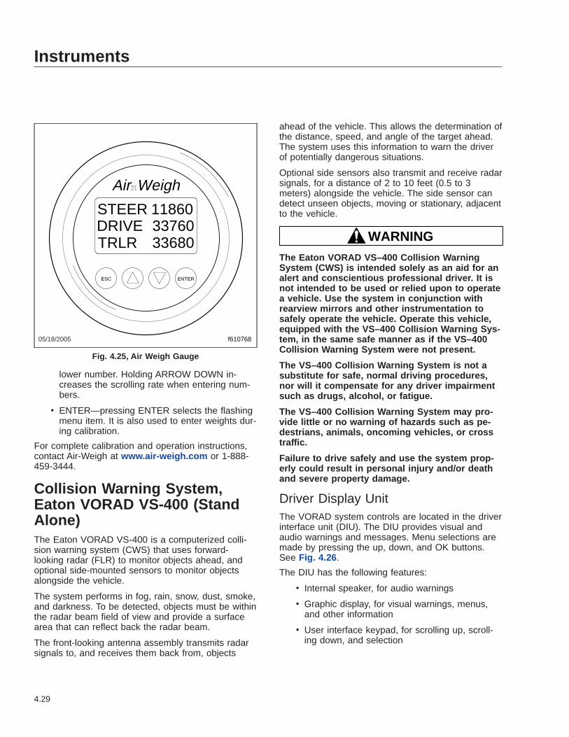
lower number. Holding ARROW DOWN in-creases the scrolling rate when entering num-bers.
• ENTER—pressing ENTER selects the flashingmenu item. It is also used to enter weights dur-ing calibration.
For complete calibration and operation instructions,contact Air-Weigh at www.air-weigh.com or 1-888-459-3444.
Collision Warning System,Eaton VORAD VS-400 (StandAlone)The Eaton VORAD VS-400 is a computerized colli-sion warning system (CWS) that uses forward-looking radar (FLR) to monitor objects ahead, andoptional side-mounted sensors to monitor objectsalongside the vehicle.
The system performs in fog, rain, snow, dust, smoke,and darkness. To be detected, objects must be withinthe radar beam field of view and provide a surfacearea that can reflect back the radar beam.
The front-looking antenna assembly transmits radarsignals to, and receives them back from, objects
ahead of the vehicle. This allows the determination ofthe distance, speed, and angle of the target ahead.The system uses this information to warn the driverof potentially dangerous situations.
Optional side sensors also transmit and receive radarsignals, for a distance of 2 to 10 feet (0.5 to 3meters) alongside the vehicle. The side sensor candetect unseen objects, moving or stationary, adjacentto the vehicle.
WARNINGThe Eaton VORAD VS–400 Collision WarningSystem (CWS) is intended solely as an aid for analert and conscientious professional driver. It isnot intended to be used or relied upon to operatea vehicle. Use the system in conjunction withrearview mirrors and other instrumentation tosafely operate the vehicle. Operate this vehicle,equipped with the VS–400 Collision Warning Sys-tem, in the same safe manner as if the VS–400Collision Warning System were not present.
The VS–400 Collision Warning System is not asubstitute for safe, normal driving procedures,nor will it compensate for any driver impairmentsuch as drugs, alcohol, or fatigue.
The VS–400 Collision Warning System may pro-vide little or no warning of hazards such as pe-destrians, animals, oncoming vehicles, or crosstraffic.
Failure to drive safely and use the system prop-erly could result in personal injury and/or deathand severe property damage.
Driver Display UnitThe VORAD system controls are located in the driverinterface unit (DIU). The DIU provides visual andaudio warnings and messages. Menu selections aremade by pressing the up, down, and OK buttons.See Fig. 4.26 .
The DIU has the following features:
• Internal speaker, for audio warnings
• Graphic display, for visual warnings, menus,and other information
• User interface keypad, for scrolling up, scroll-ing down, and selection
05/18/2005
STEERDRIVETRLR
118603376033680
ESC ENTER
Air Weigh
f610768
Fig. 4.25, Air Weigh Gauge
Instruments
4.29
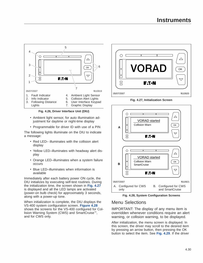
• Ambient light sensor, for auto illumination ad-justment for daytime or night-time display
• Programmable for driver ID with use of a PIN
The following lights illuminate on the DIU to indicatea message:
• Red LED– illuminates with the collision alertdisplay
• Yellow LED–illuminates with headway alert dis-play
• Orange LED–illuminates when a system failureoccurs
• Blue LED–illuminates when information isavailable
Immediately after each battery power ON cycle, theDIU initializes by executing self-test routines. Duringthe initialization time, the screen shown in Fig. 4.27is displayed and all the LED lamps are activated(power-on bulb check) for approximately 3 seconds,along with a power-up tone.
When initialization is complete, the DIU displays theVS-400 system configuration screen. Figure 4.28shows the screens for the VS-400 configured for Col-lision Warning System (CWS) and SmartCruise™,and for CWS only.
Menu SelectionsIMPORTANT: The display of any menu item isoverridden whenever conditions require an alertwarning, or collision warning, to be displayed.
After initialization, the menu screen is displayed. Inthis screen, the driver may scroll to the desired itemby pressing an arrow button, then pressing the OKbutton to select the item. See Fig. 4.29 . If the driver
05/07/2007 f610919
1
2
3
45
6
7
OK
1. Fault Indicator2. Info Indicator3. Following Distance
Lights
4. Ambient Light Sensor5. Collision Alert Lights6. User Interface Keypad7. Graphic Display
Fig. 4.26, Driver Interface Unit (DIU)
05/07/2007 f610920
OK
Fig. 4.27, Initialization Screen
05/07/2007
VORAD startedCollision WarnSmartCruise
f610921
VORAD startedCollision Warn
A
B
OK
OK
A. Configured for CWSonly
B. Configured for CWSand SmartCruise
Fig. 4.28, System Configuration Screens
Instruments
4.30
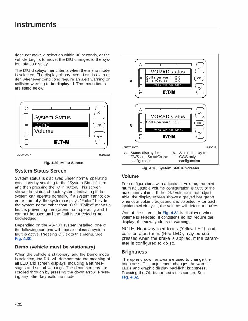
does not make a selection within 30 seconds, or thevehicle begins to move, the DIU changes to the sys-tem status display.
The DIU displays menu items when the menu modeis selected. The display of any menu item is overrid-den whenever conditions require an alert warning orcollision warning to be displayed. The menu itemsare listed below.
System Status ScreenSystem status is displayed under normal operatingconditions by scrolling to the "System Status" itemand then pressing the "OK" button. This screenshows the status of each system, indicating if thesystem can operate normally. If a system cannot op-erate normally, the system displays "Failed" besidethe system name rather than "OK". "Failed" means afault is preventing the system from operating and itcan not be used until the fault is corrected or ac-knowledged.
Depending on the VS-400 system installed, one ofthe following screens will appear unless a systemfault is active. Pressing OK exits this menu. SeeFig. 4.30 .
Demo (vehicle must be stationary)When the vehicle is stationary, and the Demo modeis selected, the DIU will demonstrate the meaning ofall LED and screen displays, including alert mes-sages and sound warnings. The demo screens arescrolled through by pressing the down arrow. Press-ing any other key exits the mode.
VolumeFor configurations with adjustable volume, the mini-mum adjustable volume configuration is 50% of themaximum volume. If the DIU volume is not adjust-able, the display screen shows a grayed bar graphwhenever volume adjustment is selected. After eachignition switch cycle, the volume will default to 100%.
One of the screens in Fig. 4.31 is displayed whenvolume is selected, if conditions do not require thedisplay of headway alerts or warnings.
NOTE: Headway alert tones (Yellow LED), andcollision alert tones (Red LED), may be sup-pressed when the brake is applied, if the param-eter is configured to do so.
BrightnessThe up and down arrows are used to change thebrightness. This adjustment changes the warningLEDs and graphic display backlight brightness.Pressing the OK button exits this screen. SeeFig. 4.32 .
f610922
System Status
VolumeDemo
05/09/2007
OK
Fig. 4.29, Menu Screen
05/07/2007 f610923
A
B
Coll ision warnSmartCruise
VORAD statusOKOK
Press OK for Menu
Coll ision warn
VORAD statusOK
Press OK for Menu
OK
OK
A. Status display forCWS and SmartCruiseconfiguration
B. Status display forCWS onlyconfiguration
Fig. 4.30, System Status Screens
Instruments
4.31
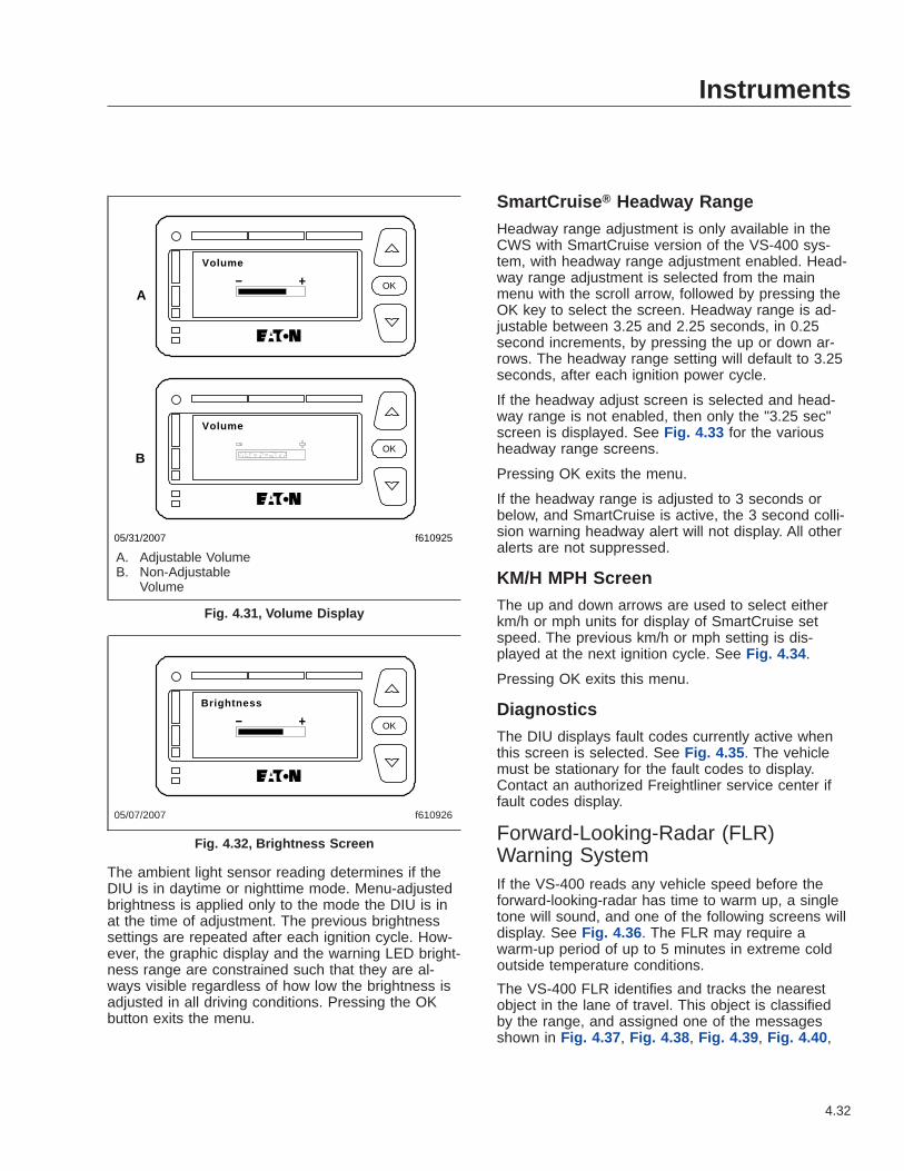
The ambient light sensor reading determines if theDIU is in daytime or nighttime mode. Menu-adjustedbrightness is applied only to the mode the DIU is inat the time of adjustment. The previous brightnesssettings are repeated after each ignition cycle. How-ever, the graphic display and the warning LED bright-ness range are constrained such that they are al-ways visible regardless of how low the brightness isadjusted in all driving conditions. Pressing the OKbutton exits the menu.
SmartCruise ® Headway RangeHeadway range adjustment is only available in theCWS with SmartCruise version of the VS-400 sys-tem, with headway range adjustment enabled. Head-way range adjustment is selected from the mainmenu with the scroll arrow, followed by pressing theOK key to select the screen. Headway range is ad-justable between 3.25 and 2.25 seconds, in 0.25second increments, by pressing the up or down ar-rows. The headway range setting will default to 3.25seconds, after each ignition power cycle.
If the headway adjust screen is selected and head-way range is not enabled, then only the "3.25 sec"screen is displayed. See Fig. 4.33 for the variousheadway range screens.
Pressing OK exits the menu.
If the headway range is adjusted to 3 seconds orbelow, and SmartCruise is active, the 3 second colli-sion warning headway alert will not display. All otheralerts are not suppressed.
KM/H MPH ScreenThe up and down arrows are used to select eitherkm/h or mph units for display of SmartCruise setspeed. The previous km/h or mph setting is dis-played at the next ignition cycle. See Fig. 4.34 .
Pressing OK exits this menu.
DiagnosticsThe DIU displays fault codes currently active whenthis screen is selected. See Fig. 4.35 . The vehiclemust be stationary for the fault codes to display.Contact an authorized Freightliner service center iffault codes display.
Forward-Looking-Radar (FLR)Warning SystemIf the VS-400 reads any vehicle speed before theforward-looking-radar has time to warm up, a singletone will sound, and one of the following screens willdisplay. See Fig. 4.36 . The FLR may require awarm-up period of up to 5 minutes in extreme coldoutside temperature conditions.
The VS-400 FLR identifies and tracks the nearestobject in the lane of travel. This object is classifiedby the range, and assigned one of the messagesshown in Fig. 4.37 , Fig. 4.38 , Fig. 4.39 , Fig. 4.40 ,
f610925
A
B
Volume
Volume
OK
OK
05/31/2007
A. Adjustable VolumeB. Non-Adjustable
Volume
Fig. 4.31, Volume Display
05/07/2007 f610926
Brightness
OK
Fig. 4.32, Brightness Screen
Instruments
4.32
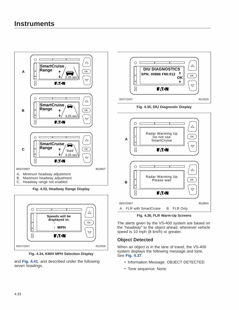
and Fig. 4.41 , and described under the followingseven headings.
The alerts given by the VS-400 system are based onthe “headway” to the object ahead, whenever vehiclespeed is 10 mph (8 km/h) or greater.
Object DetectedWhen an object is in the lane of travel, the VS-400system displays the following message and tone.See Fig. 4.37 .
• Information Message: OBJECT DETECTED
• Tone sequence: None
05/07/2007 f610927
C
3.25 sec
SmartCruiseRange
A
SmartCruiseRange
2.25 sec
B
3.25 sec
SmartCruiseRange
fixed
OK
OK
OK
A. Minimum headway adjustmentB. Maximum headway adjustmentC. Headway range not enabled
Fig. 4.33, Headway Range Display
05/07/2007 f610928
Speeds will bedisplayed in:
MPHOK
Fig. 4.34, KM/H MPH Selection Display
05/07/2007 f610929
DIU DIAGNOSTICSSPN: 00886 FMI:012
OKOK
Fig. 4.35, DIU Diagnostic Display
05/07/2007 f610924
A
B
Do not useRadar Warming Up
Radar Warming Up
SmartCruise
Please wait
OK
OK
A. FLR with SmartCruise B. FLR Only
Fig. 4.36, FLR Warm-Up Screens
Instruments
4.33
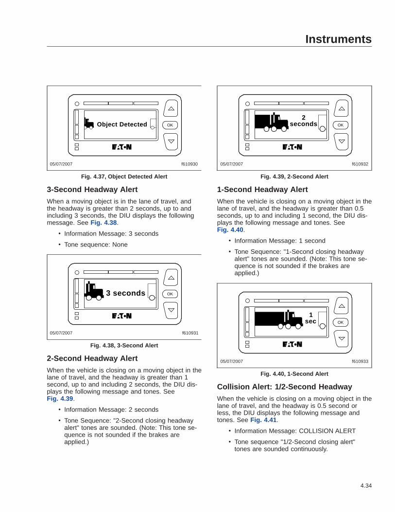
3-Second Headway AlertWhen a moving object is in the lane of travel, andthe headway is greater than 2 seconds, up to andincluding 3 seconds, the DIU displays the followingmessage. See Fig. 4.38 .
• Information Message: 3 seconds
• Tone sequence: None
2-Second Headway AlertWhen the vehicle is closing on a moving object in thelane of travel, and the headway is greater than 1second, up to and including 2 seconds, the DIU dis-plays the following message and tones. SeeFig. 4.39 .
• Information Message: 2 seconds
• Tone Sequence: "2-Second closing headwayalert" tones are sounded. (Note: This tone se-quence is not sounded if the brakes areapplied.)
1-Second Headway AlertWhen the vehicle is closing on a moving object in thelane of travel, and the headway is greater than 0.5seconds, up to and including 1 second, the DIU dis-plays the following message and tones. SeeFig. 4.40 .
• Information Message: 1 second
• Tone Sequence: "1-Second closing headwayalert" tones are sounded. (Note: This tone se-quence is not sounded if the brakes areapplied.)
Collision Alert: 1/2-Second HeadwayWhen the vehicle is closing on a moving object in thelane of travel, and the headway is 0.5 second orless, the DIU displays the following message andtones. See Fig. 4.41 .
• Information Message: COLLISION ALERT
• Tone sequence "1/2-Second closing alert"tones are sounded continuously.
05/07/2007 f610930
Object Detected OK
Fig. 4.37, Object Detected Alert
05/07/2007 f610931
3 seconds OK
Fig. 4.38, 3-Second Alert
05/07/2007 f610932
seconds2
OK
Fig. 4.39, 2-Second Alert
05/07/2007 f610933
sec1
OK
Fig. 4.40, 1-Second Alert
Instruments
4.34
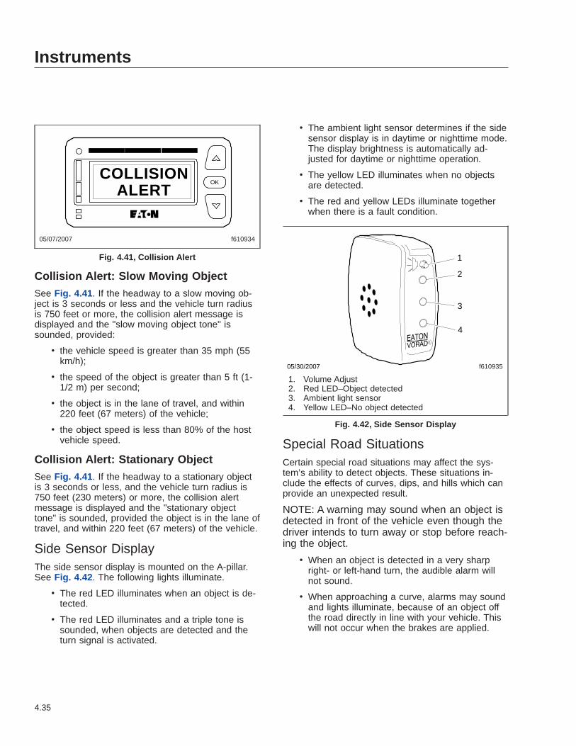
Collision Alert: Slow Moving ObjectSee Fig. 4.41 . If the headway to a slow moving ob-ject is 3 seconds or less and the vehicle turn radiusis 750 feet or more, the collision alert message isdisplayed and the "slow moving object tone" issounded, provided:
• the vehicle speed is greater than 35 mph (55km/h);
• the speed of the object is greater than 5 ft (1-1/2 m) per second;
• the object is in the lane of travel, and within220 feet (67 meters) of the vehicle;
• the object speed is less than 80% of the hostvehicle speed.
Collision Alert: Stationary ObjectSee Fig. 4.41 . If the headway to a stationary objectis 3 seconds or less, and the vehicle turn radius is750 feet (230 meters) or more, the collision alertmessage is displayed and the "stationary objecttone" is sounded, provided the object is in the lane oftravel, and within 220 feet (67 meters) of the vehicle.
Side Sensor DisplayThe side sensor display is mounted on the A-pillar.See Fig. 4.42 . The following lights illuminate.
• The red LED illuminates when an object is de-tected.
• The red LED illuminates and a triple tone issounded, when objects are detected and theturn signal is activated.
• The ambient light sensor determines if the sidesensor display is in daytime or nighttime mode.The display brightness is automatically ad-justed for daytime or nighttime operation.
• The yellow LED illuminates when no objectsare detected.
• The red and yellow LEDs illuminate togetherwhen there is a fault condition.
Special Road SituationsCertain special road situations may affect the sys-tem’s ability to detect objects. These situations in-clude the effects of curves, dips, and hills which canprovide an unexpected result.
NOTE: A warning may sound when an object isdetected in front of the vehicle even though thedriver intends to turn away or stop before reach-ing the object.
• When an object is detected in a very sharpright- or left-hand turn, the audible alarm willnot sound.
• When approaching a curve, alarms may soundand lights illuminate, because of an object offthe road directly in line with your vehicle. Thiswill not occur when the brakes are applied.
05/07/2007 f610934
COLLISIONALERT
OK
Fig. 4.41, Collision Alert
f61093505/30/2007
1
4
3
2
1. Volume Adjust2. Red LED–Object detected3. Ambient light sensor4. Yellow LED–No object detected
Fig. 4.42, Side Sensor Display
Instruments
4.35
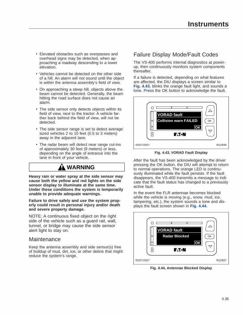
• Elevated obstacles such as overpasses andoverhead signs may be detected, when ap-proaching a roadway descending to a lowerelevation.
• Vehicles cannot be detected on the other sideof a hill. An alarm will not sound until the objectis within the antenna assembly’s field of view.
• On approaching a steep hill, objects above thebeam cannot be detected. Generally, the beamhitting the road surface does not cause analarm.
• The side sensor only detects objects within itsfield of view, next to the tractor. A vehicle far-ther back behind the field of view, will not bedetected.
• The side sensor range is set to detect averagesized vehicles 2 to 10 feet (0.5 to 3 meters)away in the adjacent lane.
• The radar beam will detect near range cut-insof approximately 30 feet (9 meters) or less,depending on the angle of entrance into thelane in front of your vehicle.
WARNINGHeavy rain or water spray at the side sensor maycause both the yellow and red lights on the sidesensor display to illuminate at the same time.Under these conditions the system is temporarilyunable to provide adequate warnings.
Failure to drive safely and use the system prop-erly could result in personal injury and/or deathand severe property damage.
NOTE: A continuous fixed object on the rightside of the vehicle such as a guard rail, wall,tunnel, or bridge may cause the side sensoralert light to stay on.
MaintenanceKeep the antenna assembly and side sensor(s) freeof buildup of mud, dirt, ice, or other debris that mightreduce the system’s range.
Failure Display Mode/Fault CodesThe VS-400 performs internal diagnostics at power-up, then continuously monitors system componentsthereafter.
If a failure is detected, depending on what featuresare affected, the DIU displays a screen similar toFig. 4.43 , blinks the orange fault light, and sounds atone. Press the OK button to acknowledge the fault.
After the fault has been acknowledged by the driverpressing the OK button, the DIU will attempt to returnto normal operations. The orange LED is continu-ously illuminated while the fault persists. If the faultdisappears, the VS-400 transmits a message to indi-cate that the fault status has changed to a previouslyactive fault.
In the event the FLR antennae becomes blockedwhile the vehicle is moving (e.g., snow, mud, ice,tampering, etc.), the system sounds a tone and dis-plays the fault screen shown in Fig. 4.44 .
05/07/2007 f610936
VORAD faultCollision warn FAILED
OK
OK
Fig. 4.43, VORAD Fault Display
05/07/2007 f610937
VORAD faultRadar Blocked
OK
OK
Fig. 4.44, Antennae Blocked Display
Instruments
4.36
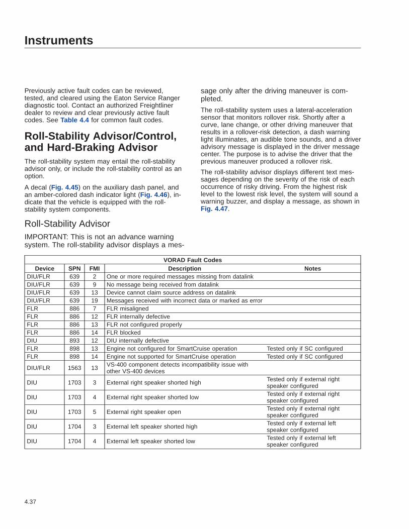
Previously active fault codes can be reviewed,tested, and cleared using the Eaton Service Rangerdiagnostic tool. Contact an authorized Freightlinerdealer to review and clear previously active faultcodes. See Table 4.4 for common fault codes.
Roll-Stability Advisor/Control,and Hard-Braking AdvisorThe roll-stability system may entail the roll-stabilityadvisor only, or include the roll-stability control as anoption.
A decal (Fig. 4.45 ) on the auxiliary dash panel, andan amber-colored dash indicator light (Fig. 4.46 ), in-dicate that the vehicle is equipped with the roll-stability system components.
Roll-Stability AdvisorIMPORTANT: This is not an advance warningsystem. The roll-stability advisor displays a mes-
sage only after the driving maneuver is com-pleted.
The roll-stability system uses a lateral-accelerationsensor that monitors rollover risk. Shortly after acurve, lane change, or other driving maneuver thatresults in a rollover-risk detection, a dash warninglight illuminates, an audible tone sounds, and a driveradvisory message is displayed in the driver messagecenter. The purpose is to advise the driver that theprevious maneuver produced a rollover risk.
The roll-stability advisor displays different text mes-sages depending on the severity of the risk of eachoccurrence of risky driving. From the highest risklevel to the lowest risk level, the system will sound awarning buzzer, and display a message, as shown inFig. 4.47 .
VORAD Fault CodesDevice SPN FMI Description Notes
DIU/FLR 639 2 One or more required messages missing from datalinkDIU/FLR 639 9 No message being received from datalinkDIU/FLR 639 13 Device cannot claim source address on datalinkDIU/FLR 639 19 Messages received with incorrect data or marked as errorFLR 886 7 FLR misalignedFLR 886 12 FLR internally defectiveFLR 886 13 FLR not configured properlyFLR 886 14 FLR blockedDIU 893 12 DIU internally defectiveFLR 898 13 Engine not configured for SmartCruise operation Tested only if SC configuredFLR 898 14 Engine not supported for SmartCruise operation Tested only if SC configured
DIU/FLR 1563 13 VS-400 component detects incompatibility issue withother VS-400 devices
DIU 1703 3 External right speaker shorted high Tested only if external rightspeaker configured
DIU 1703 4 External right speaker shorted low Tested only if external rightspeaker configured
DIU 1703 5 External right speaker open Tested only if external rightspeaker configured
DIU 1704 3 External left speaker shorted high Tested only if external leftspeaker configured
DIU 1704 4 External left speaker shorted low Tested only if external leftspeaker configured
Instruments
4.37
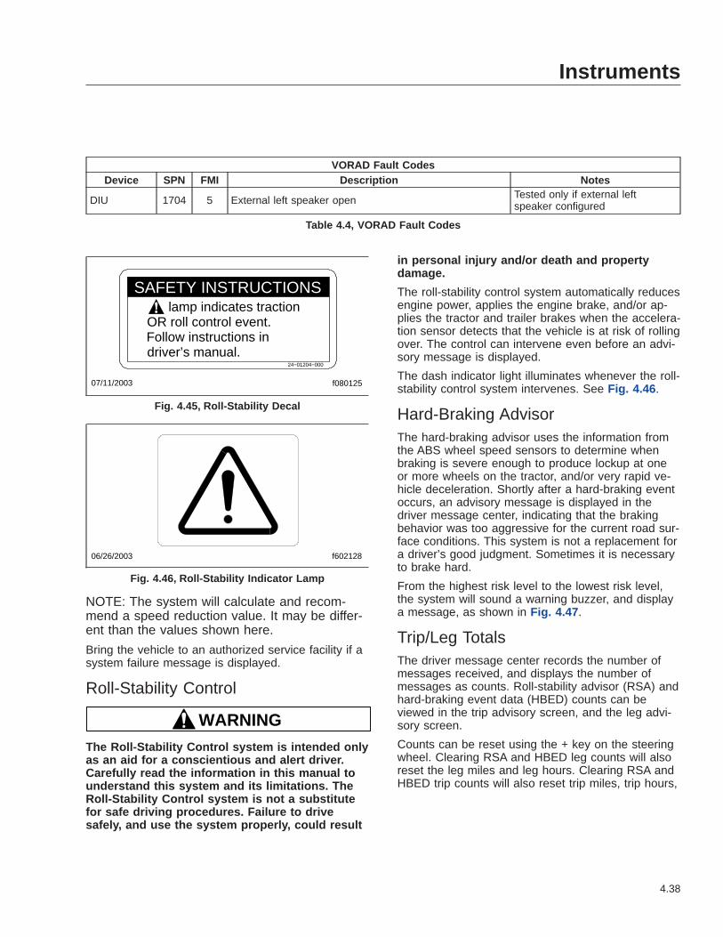
VORAD Fault CodesDevice SPN FMI Description Notes
DIU 1704 5 External left speaker open Tested only if external leftspeaker configured
Table 4.4, VORAD Fault Codes
NOTE: The system will calculate and recom-mend a speed reduction value. It may be differ-ent than the values shown here.
Bring the vehicle to an authorized service facility if asystem failure message is displayed.
Roll-Stability Control
WARNINGThe Roll-Stability Control system is intended onlyas an aid for a conscientious and alert driver.Carefully read the information in this manual tounderstand this system and its limitations. TheRoll-Stability Control system is not a substitutefor safe driving procedures. Failure to drivesafely, and use the system properly, could result
in personal injury and/or death and propertydamage.
The roll-stability control system automatically reducesengine power, applies the engine brake, and/or ap-plies the tractor and trailer brakes when the accelera-tion sensor detects that the vehicle is at risk of rollingover. The control can intervene even before an advi-sory message is displayed.
The dash indicator light illuminates whenever the roll-stability control system intervenes. See Fig. 4.46 .
Hard-Braking AdvisorThe hard-braking advisor uses the information fromthe ABS wheel speed sensors to determine whenbraking is severe enough to produce lockup at oneor more wheels on the tractor, and/or very rapid ve-hicle deceleration. Shortly after a hard-braking eventoccurs, an advisory message is displayed in thedriver message center, indicating that the brakingbehavior was too aggressive for the current road sur-face conditions. This system is not a replacement fora driver’s good judgment. Sometimes it is necessaryto brake hard.
From the highest risk level to the lowest risk level,the system will sound a warning buzzer, and displaya message, as shown in Fig. 4.47 .
Trip/Leg TotalsThe driver message center records the number ofmessages received, and displays the number ofmessages as counts. Roll-stability advisor (RSA) andhard-braking event data (HBED) counts can beviewed in the trip advisory screen, and the leg advi-sory screen.
Counts can be reset using the + key on the steeringwheel. Clearing RSA and HBED leg counts will alsoreset the leg miles and leg hours. Clearing RSA andHBED trip counts will also reset trip miles, trip hours,
lamp indicates tractionOR roll control event.Follow instructions indriver’s manual.
24−01204−000
07/11/2003 f080125
SAFETY INSTRUCTIONS
Fig. 4.45, Roll-Stability Decal
06/26/2003 f602128
Fig. 4.46, Roll-Stability Indicator Lamp
Instruments
4.38
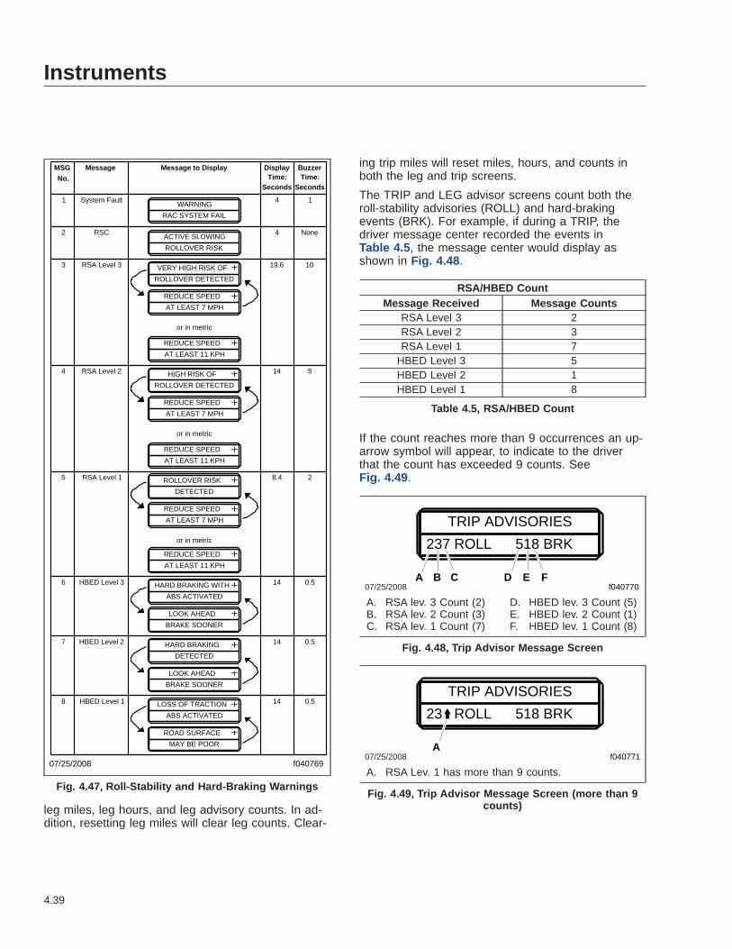
leg miles, leg hours, and leg advisory counts. In ad-dition, resetting leg miles will clear leg counts. Clear-
ing trip miles will reset miles, hours, and counts inboth the leg and trip screens.
The TRIP and LEG advisor screens count both theroll-stability advisories (ROLL) and hard-brakingevents (BRK). For example, if during a TRIP, thedriver message center recorded the events inTable 4.5 , the message center would display asshown in Fig. 4.48 .
RSA/HBED CountMessage Received Message Counts
RSA Level 3 2RSA Level 2 3RSA Level 1 7
HBED Level 3 5HBED Level 2 1HBED Level 1 8
Table 4.5, RSA/HBED Count
If the count reaches more than 9 occurrences an up-arrow symbol will appear, to indicate to the driverthat the count has exceeded 9 counts. SeeFig. 4.49 .
Message to Display
4 1
MessageMSG
No.
System Fault1WARNING
RAC SYSTEM FAIL
ACTIVE SLOWING
ROLLOVER RISK
4 NoneRSC2
VERY HIGH RISK OF
ROLLOVER DETECTED
REDUCE SPEED
AT LEAST 11 KPH
REDUCE SPEED
AT LEAST 7 MPH
or in metric
19.6 10RSA Level 33
HIGH RISK OF
ROLLOVER DETECTED
REDUCE SPEED
AT LEAST 11 KPH
REDUCE SPEED
AT LEAST 7 MPH
or in metric
14 5RSA Level 24
ROLLOVER RISK
DETECTED
REDUCE SPEED
AT LEAST 11 KPH
or in metric
REDUCE SPEED
AT LEAST 7 MPH
8.4 2RSA Level 15
HARD BRAKING WITH
ABS ACTIVATED
LOOK AHEAD
BRAKE SOONER
14 0.5HBED Level 36
HARD BRAKING
DETECTED
LOOK AHEAD
BRAKE SOONER
14 0.5HBED Level 27
LOSS OF TRACTION
ABS ACTIVATED
ROAD SURFACE
MAY BE POOR
14 0.5HBED Level 18
07/25/2008 f040769
DisplayTime:
Seconds
BuzzerTime:
Seconds
Fig. 4.47, Roll-Stability and Hard-Braking Warnings
07/25/2008
TRIP ADVISORIES
237 ROLL 518 BRK
f040770A B C D E F
A. RSA lev. 3 Count (2)B. RSA lev. 2 Count (3)C. RSA lev. 1 Count (7)
D. HBED lev. 3 Count (5)E. HBED lev. 2 Count (1)F. HBED lev. 1 Count (8)
Fig. 4.48, Trip Advisor Message Screen
07/25/2008
TRIP ADVISORIES
23 ROLL 518 BRK
f040771A
A. RSA Lev. 1 has more than 9 counts.
Fig. 4.49, Trip Advisor Message Screen (more than 9counts)
Instruments
4.39
5
Driver ControlsIgnition Switch and Key . . . . . . . . . . . . . . . . . . . . . . . . . . . . . . . . . . . . . . . . . . . . . . . . . . . . . . . . . . . . 5.1Exterior Lighting Controls . . . . . . . . . . . . . . . . . . . . . . . . . . . . . . . . . . . . . . . . . . . . . . . . . . . . . . . . . . . 5.2Interior Lighting Controls . . . . . . . . . . . . . . . . . . . . . . . . . . . . . . . . . . . . . . . . . . . . . . . . . . . . . . . . . . . 5.5Dash-Mounted Electrical Switches . . . . . . . . . . . . . . . . . . . . . . . . . . . . . . . . . . . . . . . . . . . . . . . . . . . . 5.8Guarded Switches . . . . . . . . . . . . . . . . . . . . . . . . . . . . . . . . . . . . . . . . . . . . . . . . . . . . . . . . . . . . . . . 5.10Dash-Mounted Brake Controls . . . . . . . . . . . . . . . . . . . . . . . . . . . . . . . . . . . . . . . . . . . . . . . . . . . . . . 5.12Multifunction Turn Signal Switch . . . . . . . . . . . . . . . . . . . . . . . . . . . . . . . . . . . . . . . . . . . . . . . . . . . . 5.12Steering-Wheel-Mounted Controls . . . . . . . . . . . . . . . . . . . . . . . . . . . . . . . . . . . . . . . . . . . . . . . . . . . 5.14Adjustable Steering Column . . . . . . . . . . . . . . . . . . . . . . . . . . . . . . . . . . . . . . . . . . . . . . . . . . . . . . . . 5.14
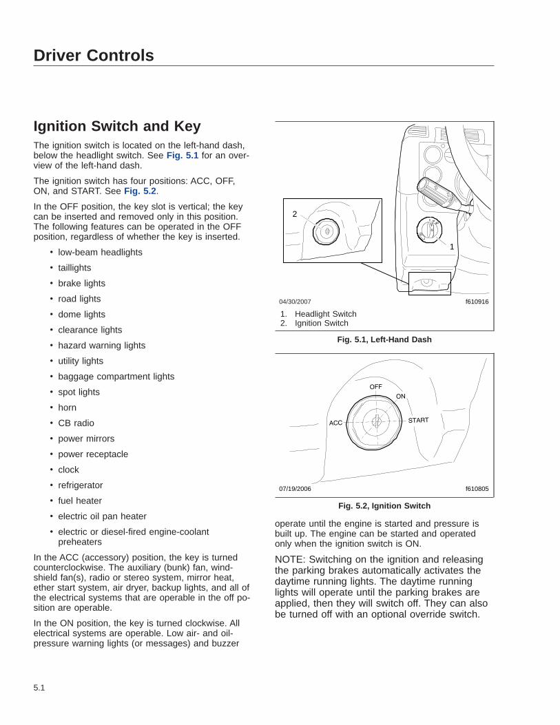
Ignition Switch and KeyThe ignition switch is located on the left-hand dash,below the headlight switch. See Fig. 5.1 for an over-view of the left-hand dash.
The ignition switch has four positions: ACC, OFF,ON, and START. See Fig. 5.2 .
In the OFF position, the key slot is vertical; the keycan be inserted and removed only in this position.The following features can be operated in the OFFposition, regardless of whether the key is inserted.
• low-beam headlights
• taillights
• brake lights
• road lights
• dome lights
• clearance lights
• hazard warning lights
• utility lights
• baggage compartment lights
• spot lights
• horn
• CB radio
• power mirrors
• power receptacle
• clock
• refrigerator
• fuel heater
• electric oil pan heater
• electric or diesel-fired engine-coolantpreheaters
In the ACC (accessory) position, the key is turnedcounterclockwise. The auxiliary (bunk) fan, wind-shield fan(s), radio or stereo system, mirror heat,ether start system, air dryer, backup lights, and all ofthe electrical systems that are operable in the off po-sition are operable.
In the ON position, the key is turned clockwise. Allelectrical systems are operable. Low air- and oil-pressure warning lights (or messages) and buzzer
operate until the engine is started and pressure isbuilt up. The engine can be started and operatedonly when the ignition switch is ON.
NOTE: Switching on the ignition and releasingthe parking brakes automatically activates thedaytime running lights. The daytime runninglights will operate until the parking brakes areapplied, then they will switch off. They can alsobe turned off with an optional override switch.
04/30/2007
1
f610916
2
1. Headlight Switch2. Ignition Switch
Fig. 5.1, Left-Hand Dash
07/19/2006 f610805
Fig. 5.2, Ignition Switch
Driver Controls
5.1
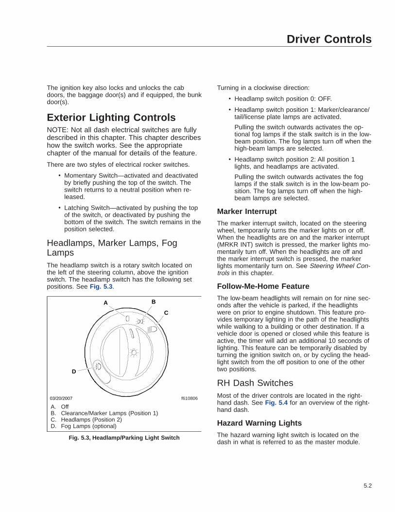
The ignition key also locks and unlocks the cabdoors, the baggage door(s) and if equipped, the bunkdoor(s).
Exterior Lighting ControlsNOTE: Not all dash electrical switches are fullydescribed in this chapter. This chapter describeshow the switch works. See the appropriatechapter of the manual for details of the feature.
There are two styles of electrical rocker switches.
• Momentary Switch—activated and deactivatedby briefly pushing the top of the switch. Theswitch returns to a neutral position when re-leased.
• Latching Switch—activated by pushing the topof the switch, or deactivated by pushing thebottom of the switch. The switch remains in theposition selected.
Headlamps, Marker Lamps, FogLampsThe headlamp switch is a rotary switch located onthe left of the steering column, above the ignitionswitch. The headlamp switch has the following setpositions. See Fig. 5.3 .
Turning in a clockwise direction:
• Headlamp switch position 0: OFF.
• Headlamp switch position 1: Marker/clearance/tail/license plate lamps are activated.
Pulling the switch outwards activates the op-tional fog lamps if the stalk switch is in the low-beam position. The fog lamps turn off when thehigh-beam lamps are selected.
• Headlamp switch position 2: All position 1lights, and headlamps are activated.
Pulling the switch outwards activates the foglamps if the stalk switch is in the low-beam po-sition. The fog lamps turn off when the high-beam lamps are selected.
Marker InterruptThe marker interrupt switch, located on the steeringwheel, temporarily turns the marker lights on or off.When the headlights are on and the marker interrupt(MRKR INT) switch is pressed, the marker lights mo-mentarily turn off. When the headlights are off andthe marker interrupt switch is pressed, the markerlights momentarily turn on. See Steering Wheel Con-trols in this chapter.
Follow-Me-Home FeatureThe low-beam headlights will remain on for nine sec-onds after the vehicle is parked, if the headlightswere on prior to engine shutdown. This feature pro-vides temporary lighting in the path of the headlightswhile walking to a building or other destination. If avehicle door is opened or closed while this feature isactive, the timer will add an additional 10 seconds oflighting. This feature can be temporarily disabled byturning the ignition switch on, or by cycling the head-light switch from the off position to one of the othertwo positions.
RH Dash SwitchesMost of the driver controls are located in the right-hand dash. See Fig. 5.4 for an overview of the right-hand dash.
Hazard Warning LightsThe hazard warning light switch is located on thedash in what is referred to as the master module.
f610806
D
A B
C
03/20/2007
A. OffB. Clearance/Marker Lamps (Position 1)C. Headlamps (Position 2)D. Fog Lamps (optional)
Fig. 5.3, Headlamp/Parking Light Switch
Driver Controls
5.2
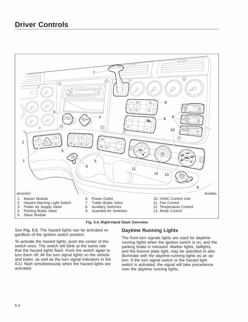
See Fig. 5.5 . The hazard lights can be activated re-gardless of the ignition switch position.
To activate the hazard lights, push the center of theswitch once. The switch will blink at the same ratethat the hazard lights flash. Push the switch again toturn them off. All the turn signal lights on the vehicleand trailer, as well as the turn signal indicators in theICU, flash simultaneously when the hazard lights areactivated.
Daytime Running LightsThe front turn signals lights are used for daytime-running lights when the ignition switch is on, and theparking brake is released. Marker lights, taillights,and the licence plate light, may be specified to alsoilluminate with the daytime-running lights as an op-tion. If the turn signal switch or the hazard lightswitch is activated, the signal will take precedenceover the daytime running lights.
MIRRHEAT
UTILLAMP
ENGBRK
ENGSHDN ENG
FANDOME
OVRD
HI
LO
AUXHIGH
DRLOVRD TRLR
AUX
MYINFO
ATC
0
2 4
8
6
FOOTWELL
POW
ER
OU
TLET
12V−10A
DO NOTENGAGEDURING
SPINLOCK UNLOCK
NTER AXLEDIFF
MUST BE LOCKED WHENVEHICLE IS IN
MOTIONUNLOCK LOCK
IFTHWHL
SLIDE
DO NOT LOWERWHEN VEHICLEIS IN MOTION SUSPAIR
LOWERAUTO
OUT
POWEROUTLET12V−10A
f610909a
1
2
34
5
56
6
8
8 9
10
1112 13
7
06/15/2007
1. Master Module2. Hazard Warning Light Switch3. Trailer Air Supply Valve4. Parking Brake Valve5. Slave Module
6. Power Outlet7. Trailer Brake Valve8. Auxiliary Switches9. Guarded Air Switches
10. HVAC Control Unit11. Fan Control12. Temperature Control13. Mode Control
Fig. 5.4, Right-Hand Dash Overview
Driver Controls
5.3
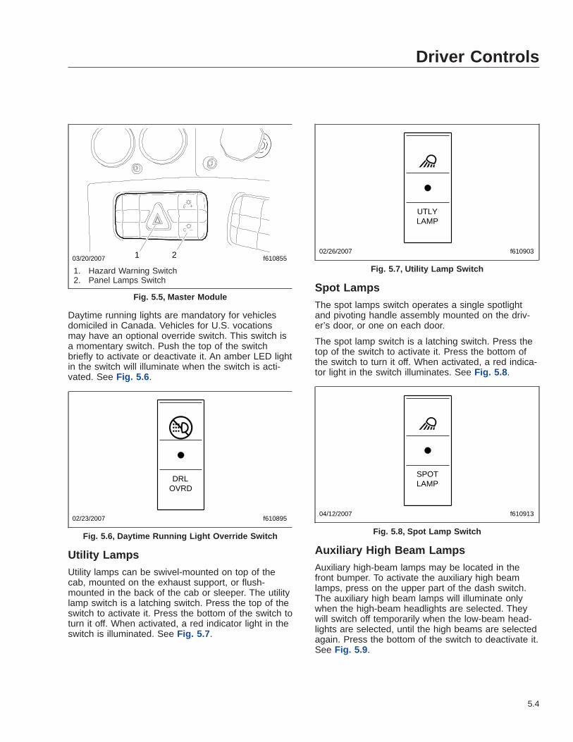
Daytime running lights are mandatory for vehiclesdomiciled in Canada. Vehicles for U.S. vocationsmay have an optional override switch. This switch isa momentary switch. Push the top of the switchbriefly to activate or deactivate it. An amber LED lightin the switch will illuminate when the switch is acti-vated. See Fig. 5.6 .
Utility LampsUtility lamps can be swivel-mounted on top of thecab, mounted on the exhaust support, or flush-mounted in the back of the cab or sleeper. The utilitylamp switch is a latching switch. Press the top of theswitch to activate it. Press the bottom of the switch toturn it off. When activated, a red indicator light in theswitch is illuminated. See Fig. 5.7 .
Spot LampsThe spot lamps switch operates a single spotlightand pivoting handle assembly mounted on the driv-er’s door, or one on each door.
The spot lamp switch is a latching switch. Press thetop of the switch to activate it. Press the bottom ofthe switch to turn it off. When activated, a red indica-tor light in the switch illuminates. See Fig. 5.8 .
Auxiliary High Beam LampsAuxiliary high-beam lamps may be located in thefront bumper. To activate the auxiliary high beamlamps, press on the upper part of the dash switch.The auxiliary high beam lamps will illuminate onlywhen the high-beam headlights are selected. Theywill switch off temporarily when the low-beam head-lights are selected, until the high beams are selectedagain. Press the bottom of the switch to deactivate it.See Fig. 5.9 .
03/20/2007 1 f6108552
1. Hazard Warning Switch2. Panel Lamps Switch
Fig. 5.5, Master Module
DRLOVRD
f61089502/23/2007
Fig. 5.6, Daytime Running Light Override Switch
UTLYLAMP
f61090302/26/2007
Fig. 5.7, Utility Lamp Switch
SPOTLAMP
f61091304/12/2007
Fig. 5.8, Spot Lamp Switch
Driver Controls
5.4
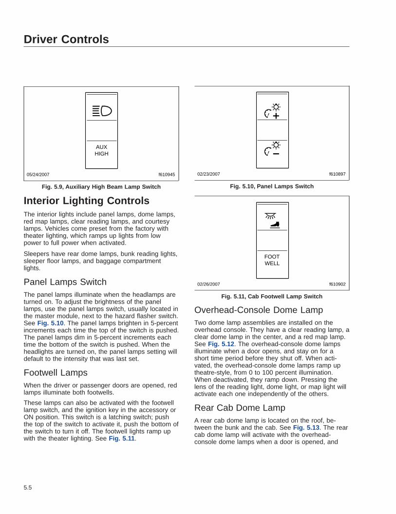
Interior Lighting ControlsThe interior lights include panel lamps, dome lamps,red map lamps, clear reading lamps, and courtesylamps. Vehicles come preset from the factory withtheater lighting, which ramps up lights from lowpower to full power when activated.
Sleepers have rear dome lamps, bunk reading lights,sleeper floor lamps, and baggage compartmentlights.
Panel Lamps SwitchThe panel lamps illuminate when the headlamps areturned on. To adjust the brightness of the panellamps, use the panel lamps switch, usually located inthe master module, next to the hazard flasher switch.See Fig. 5.10 . The panel lamps brighten in 5-percentincrements each time the top of the switch is pushed.The panel lamps dim in 5-percent increments eachtime the bottom of the switch is pushed. When theheadlights are turned on, the panel lamps setting willdefault to the intensity that was last set.
Footwell LampsWhen the driver or passenger doors are opened, redlamps illuminate both footwells.
These lamps can also be activated with the footwelllamp switch, and the ignition key in the accessory orON position. This switch is a latching switch; pushthe top of the switch to activate it, push the bottom ofthe switch to turn it off. The footwell lights ramp upwith the theater lighting. See Fig. 5.11 .
Overhead-Console Dome LampTwo dome lamp assemblies are installed on theoverhead console. They have a clear reading lamp, aclear dome lamp in the center, and a red map lamp.See Fig. 5.12 . The overhead-console dome lampsilluminate when a door opens, and stay on for ashort time period before they shut off. When acti-vated, the overhead-console dome lamps ramp uptheatre-style, from 0 to 100 percent illumination.When deactivated, they ramp down. Pressing thelens of the reading light, dome light, or map light willactivate each one independently of the others.
Rear Cab Dome LampA rear cab dome lamp is located on the roof, be-tween the bunk and the cab. See Fig. 5.13 . The rearcab dome lamp will activate with the overhead-console dome lamps when a door is opened, and
AUXHIGH
f61094505/24/2007
Fig. 5.9, Auxiliary High Beam Lamp Switch
f61089702/23/2007
Fig. 5.10, Panel Lamps Switch
FOOTWELL
f61090202/26/2007
Fig. 5.11, Cab Footwell Lamp Switch
Driver Controls
5.5
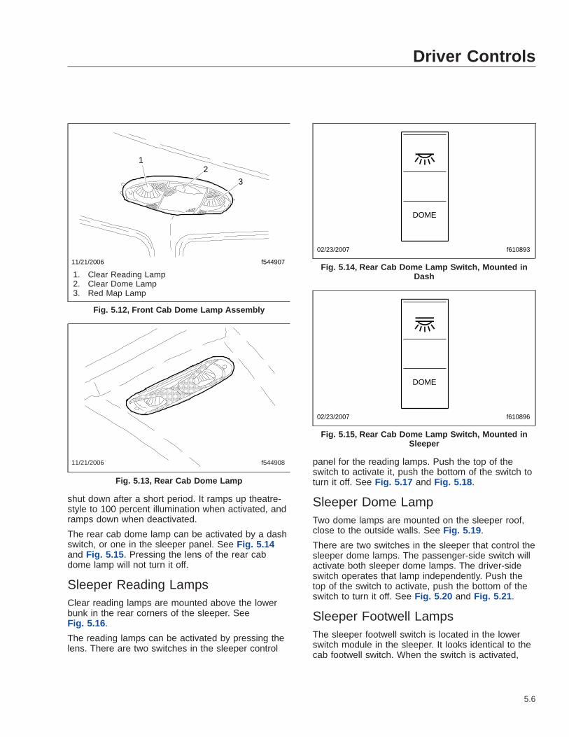
shut down after a short period. It ramps up theatre-style to 100 percent illumination when activated, andramps down when deactivated.
The rear cab dome lamp can be activated by a dashswitch, or one in the sleeper panel. See Fig. 5.14and Fig. 5.15 . Pressing the lens of the rear cabdome lamp will not turn it off.
Sleeper Reading LampsClear reading lamps are mounted above the lowerbunk in the rear corners of the sleeper. SeeFig. 5.16 .
The reading lamps can be activated by pressing thelens. There are two switches in the sleeper control
panel for the reading lamps. Push the top of theswitch to activate it, push the bottom of the switch toturn it off. See Fig. 5.17 and Fig. 5.18 .
Sleeper Dome LampTwo dome lamps are mounted on the sleeper roof,close to the outside walls. See Fig. 5.19 .
There are two switches in the sleeper that control thesleeper dome lamps. The passenger-side switch willactivate both sleeper dome lamps. The driver-sideswitch operates that lamp independently. Push thetop of the switch to activate, push the bottom of theswitch to turn it off. See Fig. 5.20 and Fig. 5.21 .
Sleeper Footwell LampsThe sleeper footwell switch is located in the lowerswitch module in the sleeper. It looks identical to thecab footwell switch. When the switch is activated,
11/21/2006 f544907
12
3
1. Clear Reading Lamp2. Clear Dome Lamp3. Red Map Lamp
Fig. 5.12, Front Cab Dome Lamp Assembly
11/21/2006 f544908
Fig. 5.13, Rear Cab Dome Lamp
f61089302/23/2007
DOME
Fig. 5.14, Rear Cab Dome Lamp Switch, Mounted inDash
f61089602/23/2007
DOME
Fig. 5.15, Rear Cab Dome Lamp Switch, Mounted inSleeper
Driver Controls
5.6
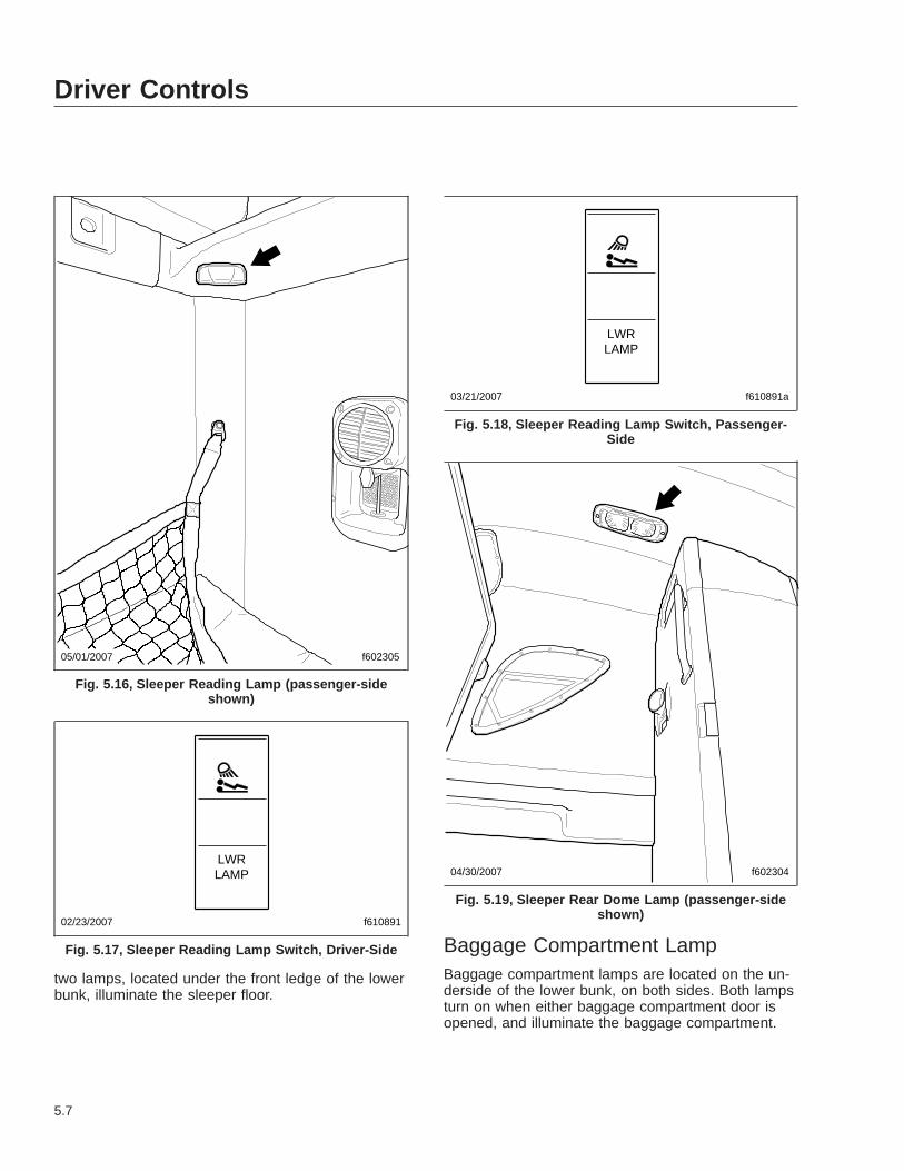
two lamps, located under the front ledge of the lowerbunk, illuminate the sleeper floor.
Baggage Compartment LampBaggage compartment lamps are located on the un-derside of the lower bunk, on both sides. Both lampsturn on when either baggage compartment door isopened, and illuminate the baggage compartment.
05/01/2007 f602305
Fig. 5.16, Sleeper Reading Lamp (passenger-sideshown)
LWRLAMP
f61089102/23/2007
Fig. 5.17, Sleeper Reading Lamp Switch, Driver-Side
LWRLAMP
f610891a03/21/2007
Fig. 5.18, Sleeper Reading Lamp Switch, Passenger-Side
04/30/2007 f602304
Fig. 5.19, Sleeper Rear Dome Lamp (passenger-sideshown)
Driver Controls
5.7
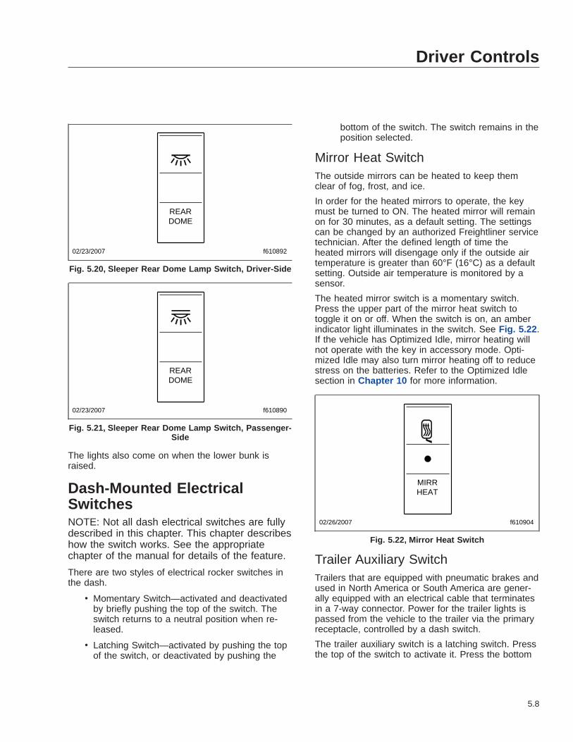
The lights also come on when the lower bunk israised.
Dash-Mounted ElectricalSwitchesNOTE: Not all dash electrical switches are fullydescribed in this chapter. This chapter describeshow the switch works. See the appropriatechapter of the manual for details of the feature.
There are two styles of electrical rocker switches inthe dash.
• Momentary Switch—activated and deactivatedby briefly pushing the top of the switch. Theswitch returns to a neutral position when re-leased.
• Latching Switch—activated by pushing the topof the switch, or deactivated by pushing the
bottom of the switch. The switch remains in theposition selected.
Mirror Heat SwitchThe outside mirrors can be heated to keep themclear of fog, frost, and ice.
In order for the heated mirrors to operate, the keymust be turned to ON. The heated mirror will remainon for 30 minutes, as a default setting. The settingscan be changed by an authorized Freightliner servicetechnician. After the defined length of time theheated mirrors will disengage only if the outside airtemperature is greater than 60°F (16°C) as a defaultsetting. Outside air temperature is monitored by asensor.
The heated mirror switch is a momentary switch.Press the upper part of the mirror heat switch totoggle it on or off. When the switch is on, an amberindicator light illuminates in the switch. See Fig. 5.22 .If the vehicle has Optimized Idle, mirror heating willnot operate with the key in accessory mode. Opti-mized Idle may also turn mirror heating off to reducestress on the batteries. Refer to the Optimized Idlesection in Chapter 10 for more information.
Trailer Auxiliary SwitchTrailers that are equipped with pneumatic brakes andused in North America or South America are gener-ally equipped with an electrical cable that terminatesin a 7-way connector. Power for the trailer lights ispassed from the vehicle to the trailer via the primaryreceptacle, controlled by a dash switch.
The trailer auxiliary switch is a latching switch. Pressthe top of the switch to activate it. Press the bottom
REARDOME
f61089202/23/2007
Fig. 5.20, Sleeper Rear Dome Lamp Switch, Driver-Side
REARDOME
f61089002/23/2007
Fig. 5.21, Sleeper Rear Dome Lamp Switch, Passenger-Side
MIRRHEAT
f61090402/26/2007
Fig. 5.22, Mirror Heat Switch
Driver Controls
5.8
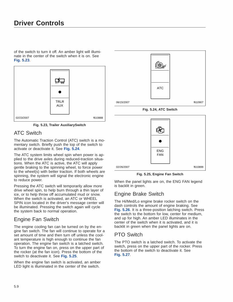
of the switch to turn it off. An amber light will illumi-nate in the center of the switch when it is on. SeeFig. 5.23 .
ATC SwitchThe Automatic Traction Control (ATC) switch is a mo-mentary switch. Briefly push the top of the switch toactivate or deactivate it. See Fig. 5.24 .
The ATC system limits wheel spin when power is ap-plied to the drive axles during reduced-traction situa-tions. When the ATC is active, the ATC will applygentle braking to the spinning wheel, to force powerto the wheel(s) with better traction. If both wheels arespinning, the system will signal the electronic engineto reduce power.
Pressing the ATC switch will temporarily allow moredrive wheel spin, to help burn through a thin layer ofice, or to help throw off accumulated mud or snow.When the switch is activated, an ATC or WHEELSPIN icon located in the driver’s message center willbe illuminated. Pressing the switch again will cyclethe system back to normal operation.
Engine Fan SwitchThe engine cooling fan can be turned on by the en-gine fan switch. The fan will continue to operate for aset amount of time and then turn off unless the cool-ant temperature is high enough to continue the fanoperation. The engine fan switch is a latched switch.To turn the engine fan on, press on the upper part ofthe rocker (at the fan icon). Press the bottom of theswitch to deactivate it. See Fig. 5.25 .
When the engine fan switch is activated, an amberLED light is illuminated in the center of the switch.
When the panel lights are on, the ENG FAN legendis backlit in green.
Engine Brake SwitchThe Hi/Med/Lo engine brake rocker switch on thedash controls the amount of engine braking. SeeFig. 5.26 . It is a three-position latching switch. Pressthe switch to the bottom for low, center for medium,and up for high. An amber LED illuminates in thecenter of the switch when it is activated, and it isbacklit in green when the panel lights are on.
PTO SwitchThe PTO switch is a latched switch. To activate theswitch, press on the upper part of the rocker. Pressthe bottom of the switch to deactivate it. SeeFig. 5.27 .
TRLRAUX
f61088802/23/2007
Fig. 5.23, Trailer AuxiliarySwitch
f61090706/15/2007
ATC
Fig. 5.24, ATC Switch
ENGFAN
f61089902/26/2007
Fig. 5.25, Engine Fan Switch
Driver Controls
5.9
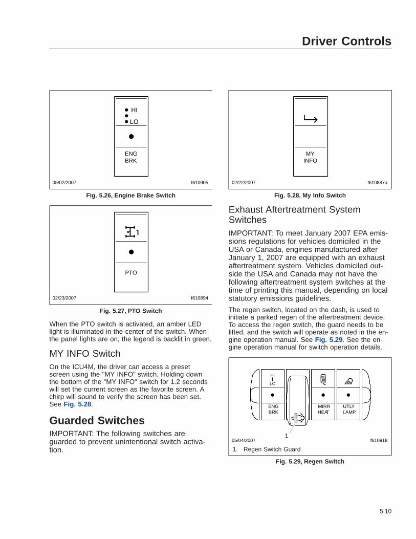
When the PTO switch is activated, an amber LEDlight is illuminated in the center of the switch. Whenthe panel lights are on, the legend is backlit in green.
MY INFO SwitchOn the ICU4M, the driver can access a presetscreen using the "MY INFO" switch. Holding downthe bottom of the "MY INFO" switch for 1.2 secondswill set the current screen as the favorite screen. Achirp will sound to verify the screen has been set.See Fig. 5.28 .
Guarded SwitchesIMPORTANT: The following switches areguarded to prevent unintentional switch activa-tion.
Exhaust Aftertreatment SystemSwitchesIMPORTANT: To meet January 2007 EPA emis-sions regulations for vehicles domiciled in theUSA or Canada, engines manufactured afterJanuary 1, 2007 are equipped with an exhaustaftertreatment system. Vehicles domiciled out-side the USA and Canada may not have thefollowing aftertreatment system switches at thetime of printing this manual, depending on localstatutory emissions guidelines.
The regen switch, located on the dash, is used toinitiate a parked regen of the aftertreatment device.To access the regen switch, the guard needs to belifted, and the switch will operate as noted in the en-gine operation manual. See Fig. 5.29 . See the en-gine operation manual for switch operation details.
ENGBRK
f61090505/02/2007
HI
LO
Fig. 5.26, Engine Brake Switch
f61089402/23/2007
PTO
Fig. 5.27, PTO Switch
02/22/2007
MYINFO
f610887a
Fig. 5.28, My Info Switch
LAMPUTLY
HEATMIRR
BRKENG
HI
LO
05/04/2007 f6109181
1. Regen Switch Guard
Fig. 5.29, Regen Switch
Driver Controls
5.10
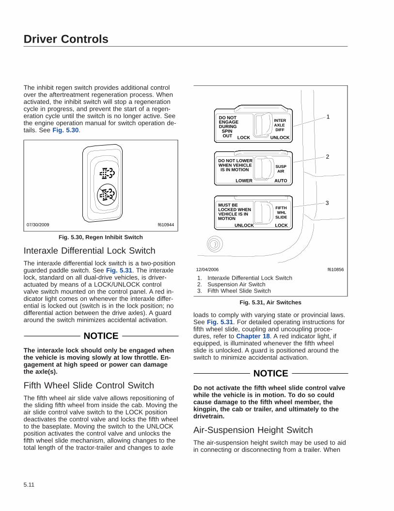
The inhibit regen switch provides additional controlover the aftertreatment regeneration process. Whenactivated, the inhibit switch will stop a regenerationcycle in progress, and prevent the start of a regen-eration cycle until the switch is no longer active. Seethe engine operation manual for switch operation de-tails. See Fig. 5.30 .
Interaxle Differential Lock SwitchThe interaxle differential lock switch is a two-positionguarded paddle switch. See Fig. 5.31 . The interaxlelock, standard on all dual-drive vehicles, is driver-actuated by means of a LOCK/UNLOCK controlvalve switch mounted on the control panel. A red in-dicator light comes on whenever the interaxle differ-ential is locked out (switch is in the lock position; nodifferential action between the drive axles). A guardaround the switch minimizes accidental activation.
NOTICEThe interaxle lock should only be engaged whenthe vehicle is moving slowly at low throttle. En-gagement at high speed or power can damagethe axle(s).
Fifth Wheel Slide Control SwitchThe fifth wheel air slide valve allows repositioning ofthe sliding fifth wheel from inside the cab. Moving theair slide control valve switch to the LOCK positiondeactivates the control valve and locks the fifth wheelto the baseplate. Moving the switch to the UNLOCKposition activates the control valve and unlocks thefifth wheel slide mechanism, allowing changes to thetotal length of the tractor-trailer and changes to axle
loads to comply with varying state or provincial laws.See Fig. 5.31 . For detailed operating instructions forfifth wheel slide, coupling and uncoupling proce-dures, refer to Chapter 18 . A red indicator light, ifequipped, is illuminated whenever the fifth wheelslide is unlocked. A guard is positioned around theswitch to minimize accidental activation.
NOTICEDo not activate the fifth wheel slide control valvewhile the vehicle is in motion. To do so couldcause damage to the fifth wheel member, thekingpin, the cab or trailer, and ultimately to thedrivetrain.
Air-Suspension Height SwitchThe air-suspension height switch may be used to aidin connecting or disconnecting from a trailer. When
f61094407/30/2009
Fig. 5.30, Regen Inhibit Switch
DO NOTENGAGEDURING
SPINOUT LOCK UNLOCK
INTERAXLEDIFF
DO NOT LOWERWHEN VEHICLEIS IN MOTION
LOWER AUTO
SUSPAIR
LOCKUNLOCK
FIFTHWHL
SLIDE
MUST BELOCKED WHENVEHICLE IS INMOTION
12/04/2006 f610856
1
2
3
1. Interaxle Differential Lock Switch2. Suspension Air Switch3. Fifth Wheel Slide Switch
Fig. 5.31, Air Switches
Driver Controls
5.11
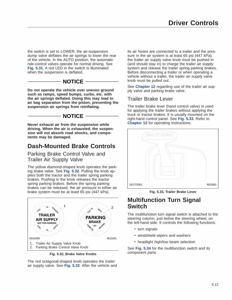
the switch is set to LOWER, the air-suspensiondump valve deflates the air springs to lower the rearof the vehicle. In the AUTO position, the automaticride-control valves operate for normal driving. SeeFig. 5.31 . A red LED in the switch is illuminatedwhen the suspension is deflated.
NOTICEDo not operate the vehicle over uneven groundsuch as ramps, speed bumps, curbs, etc. withthe air springs deflated. Doing this may lead toair bag separation from the piston, preventing thesuspension air springs from reinflating.
NOTICENever exhaust air from the suspension whiledriving. When the air is exhausted, the suspen-sion will not absorb road shocks, and compo-nents may be damaged.
Dash-Mounted Brake ControlsParking Brake Control Valve andTrailer Air Supply ValveThe yellow diamond-shaped knob operates the park-ing brake valve. See Fig. 5.32 . Pulling the knob ap-plies both the tractor and the trailer spring parkingbrakes. Pushing in the knob releases the tractorspring parking brakes. Before the spring parkingbrakes can be released, the air pressure in either airbrake system must be at least 65 psi (447 kPa).
The red octagonal-shaped knob operates the trailerair supply valve. See Fig. 5.32 . After the vehicle and
its air hoses are connected to a trailer and the pres-sure in the air system is at least 65 psi (447 kPa),the trailer air supply valve knob must be pushed in(and should stay in) to charge the trailer air supplysystem and release the trailer spring parking brakes.Before disconnecting a trailer or when operating avehicle without a trailer, the trailer air supply valveknob must be pulled out.
See Chapter 12 regarding use of the trailer air sup-ply valve and parking brake valve.
Trailer Brake LeverThe trailer brake lever (hand control valve) is usedfor applying the trailer brakes without applying thetruck or tractor brakes. It is usually mounted on theright-hand control panel. See Fig. 5.33 . Refer toChapter 12 for operating instructions.
Multifunction Turn SignalSwitchThe multifunction turn signal switch is attached to thesteering column, just below the steering wheel, onthe left-hand side. It controls the following functions:
• turn signals
• windshield wipers and washers
• headlight high/low beam selection
See Fig. 5.34 for the multifunction switch and itscomponent parts.
f610291
1 2
03/10/99
1. Trailer Air Supply Valve Knob2. Parking Brake Control Valve Knob
Fig. 5.32, Brake Valve Knobs
10/17/2001 f610591
Fig. 5.33, Trailer Brake Lever
Driver Controls
5.12
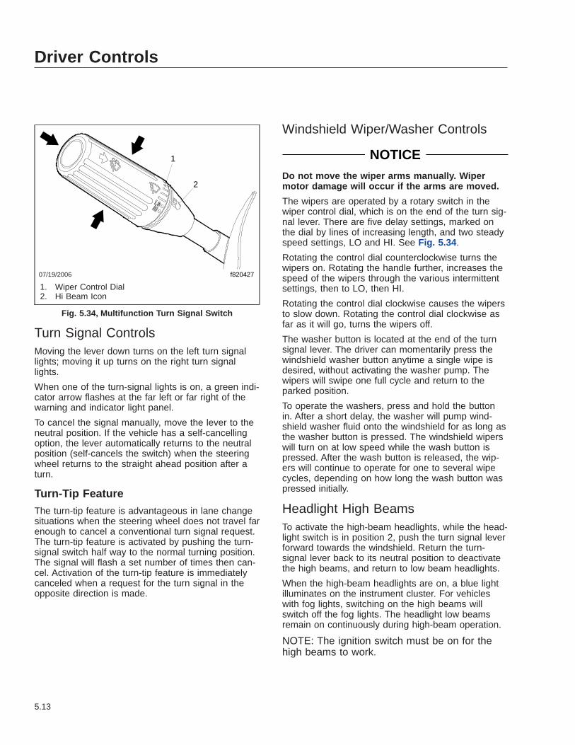
Turn Signal ControlsMoving the lever down turns on the left turn signallights; moving it up turns on the right turn signallights.
When one of the turn-signal lights is on, a green indi-cator arrow flashes at the far left or far right of thewarning and indicator light panel.
To cancel the signal manually, move the lever to theneutral position. If the vehicle has a self-cancellingoption, the lever automatically returns to the neutralposition (self-cancels the switch) when the steeringwheel returns to the straight ahead position after aturn.
Turn-Tip FeatureThe turn-tip feature is advantageous in lane changesituations when the steering wheel does not travel farenough to cancel a conventional turn signal request.The turn-tip feature is activated by pushing the turn-signal switch half way to the normal turning position.The signal will flash a set number of times then can-cel. Activation of the turn-tip feature is immediatelycanceled when a request for the turn signal in theopposite direction is made.
Windshield Wiper/Washer Controls
NOTICEDo not move the wiper arms manually. Wipermotor damage will occur if the arms are moved.
The wipers are operated by a rotary switch in thewiper control dial, which is on the end of the turn sig-nal lever. There are five delay settings, marked onthe dial by lines of increasing length, and two steadyspeed settings, LO and HI. See Fig. 5.34 .
Rotating the control dial counterclockwise turns thewipers on. Rotating the handle further, increases thespeed of the wipers through the various intermittentsettings, then to LO, then HI.
Rotating the control dial clockwise causes the wipersto slow down. Rotating the control dial clockwise asfar as it will go, turns the wipers off.
The washer button is located at the end of the turnsignal lever. The driver can momentarily press thewindshield washer button anytime a single wipe isdesired, without activating the washer pump. Thewipers will swipe one full cycle and return to theparked position.
To operate the washers, press and hold the buttonin. After a short delay, the washer will pump wind-shield washer fluid onto the windshield for as long asthe washer button is pressed. The windshield wiperswill turn on at low speed while the wash button ispressed. After the wash button is released, the wip-ers will continue to operate for one to several wipecycles, depending on how long the wash button waspressed initially.
Headlight High BeamsTo activate the high-beam headlights, while the head-light switch is in position 2, push the turn signal leverforward towards the windshield. Return the turn-signal lever back to its neutral position to deactivatethe high beams, and return to low beam headlights.
When the high-beam headlights are on, a blue lightilluminates on the instrument cluster. For vehicleswith fog lights, switching on the high beams willswitch off the fog lights. The headlight low beamsremain on continuously during high-beam operation.
NOTE: The ignition switch must be on for thehigh beams to work.
07/19/2006 f820427
1
2
1. Wiper Control Dial2. Hi Beam Icon
Fig. 5.34, Multifunction Turn Signal Switch
Driver Controls
5.13
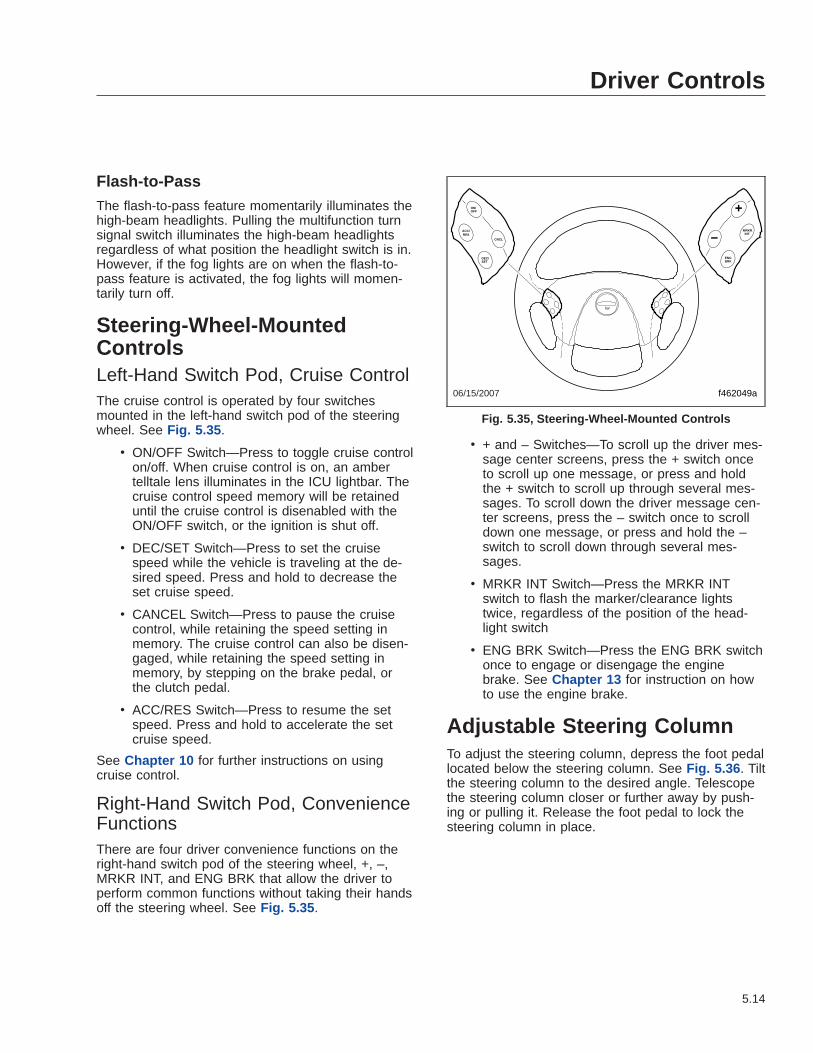
Flash-to-PassThe flash-to-pass feature momentarily illuminates thehigh-beam headlights. Pulling the multifunction turnsignal switch illuminates the high-beam headlightsregardless of what position the headlight switch is in.However, if the fog lights are on when the flash-to-pass feature is activated, the fog lights will momen-tarily turn off.
Steering-Wheel-MountedControlsLeft-Hand Switch Pod, Cruise ControlThe cruise control is operated by four switchesmounted in the left-hand switch pod of the steeringwheel. See Fig. 5.35 .
• ON/OFF Switch—Press to toggle cruise controlon/off. When cruise control is on, an ambertelltale lens illuminates in the ICU lightbar. Thecruise control speed memory will be retaineduntil the cruise control is disenabled with theON/OFF switch, or the ignition is shut off.
• DEC/SET Switch—Press to set the cruisespeed while the vehicle is traveling at the de-sired speed. Press and hold to decrease theset cruise speed.
• CANCEL Switch—Press to pause the cruisecontrol, while retaining the speed setting inmemory. The cruise control can also be disen-gaged, while retaining the speed setting inmemory, by stepping on the brake pedal, orthe clutch pedal.
• ACC/RES Switch—Press to resume the setspeed. Press and hold to accelerate the setcruise speed.
See Chapter 10 for further instructions on usingcruise control.
Right-Hand Switch Pod, ConvenienceFunctionsThere are four driver convenience functions on theright-hand switch pod of the steering wheel, +, –,MRKR INT, and ENG BRK that allow the driver toperform common functions without taking their handsoff the steering wheel. See Fig. 5.35 .
• + and – Switches—To scroll up the driver mes-sage center screens, press the + switch onceto scroll up one message, or press and holdthe + switch to scroll up through several mes-sages. To scroll down the driver message cen-ter screens, press the – switch once to scrolldown one message, or press and hold the –switch to scroll down through several mes-sages.
• MRKR INT Switch—Press the MRKR INTswitch to flash the marker/clearance lightstwice, regardless of the position of the head-light switch
• ENG BRK Switch—Press the ENG BRK switchonce to engage or disengage the enginebrake. See Chapter 13 for instruction on howto use the engine brake.
Adjustable Steering ColumnTo adjust the steering column, depress the foot pedallocated below the steering column. See Fig. 5.36 . Tiltthe steering column to the desired angle. Telescopethe steering column closer or further away by push-ing or pulling it. Release the foot pedal to lock thesteering column in place.
06/15/2007
ON/OFF
ACC/RES
CNCL
DEC/SET
MRKRINT
ENGBRK
−
+
f462049a
Fig. 5.35, Steering-Wheel-Mounted Controls
Driver Controls
5.14
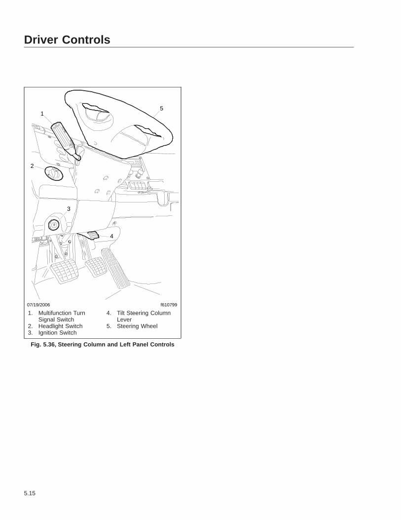
07/19/2006 f610799
1
2
3
4
5
1. Multifunction TurnSignal Switch
2. Headlight Switch3. Ignition Switch
4. Tilt Steering ColumnLever
5. Steering Wheel
Fig. 5.36, Steering Column and Left Panel Controls
Driver Controls
5.15
6
Seats and RestraintsGeneral Information . . . . . . . . . . . . . . . . . . . . . . . . . . . . . . . . . . . . . . . . . . . . . . . . . . . . . . . . . . . . . . . 6.1Cascadia High-Back Seat . . . . . . . . . . . . . . . . . . . . . . . . . . . . . . . . . . . . . . . . . . . . . . . . . . . . . . . . . . 6.2Sears Atlas Seat . . . . . . . . . . . . . . . . . . . . . . . . . . . . . . . . . . . . . . . . . . . . . . . . . . . . . . . . . . . . . . . . . . 6.2Seat Belts and Tether Belts . . . . . . . . . . . . . . . . . . . . . . . . . . . . . . . . . . . . . . . . . . . . . . . . . . . . . . . . . 6.3Steering Wheel Air Bag . . . . . . . . . . . . . . . . . . . . . . . . . . . . . . . . . . . . . . . . . . . . . . . . . . . . . . . . . . . . 6.7RollTek Rollover Protection System . . . . . . . . . . . . . . . . . . . . . . . . . . . . . . . . . . . . . . . . . . . . . . . . . . . 6.8
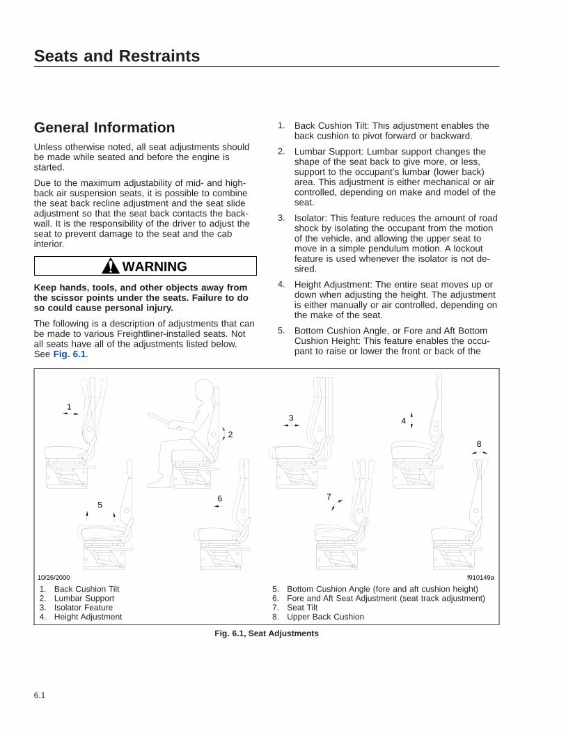
General InformationUnless otherwise noted, all seat adjustments shouldbe made while seated and before the engine isstarted.
Due to the maximum adjustability of mid- and high-back air suspension seats, it is possible to combinethe seat back recline adjustment and the seat slideadjustment so that the seat back contacts the back-wall. It is the responsibility of the driver to adjust theseat to prevent damage to the seat and the cabinterior.
WARNINGKeep hands, tools, and other objects away fromthe scissor points under the seats. Failure to doso could cause personal injury.
The following is a description of adjustments that canbe made to various Freightliner-installed seats. Notall seats have all of the adjustments listed below.See Fig. 6.1 .
1. Back Cushion Tilt: This adjustment enables theback cushion to pivot forward or backward.
2. Lumbar Support: Lumbar support changes theshape of the seat back to give more, or less,support to the occupant’s lumbar (lower back)area. This adjustment is either mechanical or aircontrolled, depending on make and model of theseat.
3. Isolator: This feature reduces the amount of roadshock by isolating the occupant from the motionof the vehicle, and allowing the upper seat tomove in a simple pendulum motion. A lockoutfeature is used whenever the isolator is not de-sired.
4. Height Adjustment: The entire seat moves up ordown when adjusting the height. The adjustmentis either manually or air controlled, depending onthe make of the seat.
5. Bottom Cushion Angle, or Fore and Aft BottomCushion Height: This feature enables the occu-pant to raise or lower the front or back of the
10/26/2000 f910149a
1
2
3 4
56 7
8
1. Back Cushion Tilt2. Lumbar Support3. Isolator Feature4. Height Adjustment
5. Bottom Cushion Angle (fore and aft cushion height)6. Fore and Aft Seat Adjustment (seat track adjustment)7. Seat Tilt8. Upper Back Cushion
Fig. 6.1, Seat Adjustments
Seats and Restraints
6.1
bottom cushion. This adjustment is easier to per-form when all weight is removed from the seat.
6. Fore and Aft Seat (seat track adjustment): Theentire seat moves forward or backward when thisadjustment is made.
7. Seat Tilt: When this adjustment is made, the seatassembly (back and bottom cushions) tilts for-ward or backward.
8. Upper Back Cushion Adjustment: When this ad-justment is made, the upper back cushionchanges angle to provide upper back support.
9. Weight Adjustment: On those seats with weightadjustment, the feature is fully automatic. Whenyou sit on the seat, a leveling valve places you inthe center of the ride zone. Additional adjust-ments are possible by using the height adjust-ment feature.
Cascadia High-Back SeatSee Fig. 6.2 for seat adjustment controls.
1. Rear Cushion Adjustment Knob—To adjust theheight of the rear of the seat cushion, removeyour weight from the seat and turn the rear cush-ion adjustment knob to one of three positions.
2. Fore and Aft Isolator— the isolator reduces theamount of road shock, by isolating the occupantfrom the motion of the vehicle, and allowing theseat to move in a simple pendulum motion. Touse the isolator feature, turn the isolator knobrearward to the unlocked position. Turn the isola-tor knob forward to the locked position when theisolator feature is not desired.
3. Front Cushion Adjustment Knob—To adjust theheight of the front of the cushion, remove yourweight from the seat, then turn the adjustmentknob toward the front of the seat (clockwise) toincrease cushion height. To lower the cushionheight, turn the adjustment knob toward the rearof the seat (counterclockwise).
4. Fore and Aft Cushion Adjustment Handle—Toadjust the fore and aft position of the seat cush-ion, remove your weight from the seat, then liftup and pull forward on the cushion adjustmenthandle. To return the cushion to the aft position,lift up and push rearward.
5. Fore and Aft Seat Adjustment Lever—To adjustthe fore and aft position of the entire seat, movethe fore and aft seat adjustment lever to the leftand slide the seat forward or backward to thedesired position. Move the lever back to its origi-nal position to lock the seat in place.
6. Back Cushion Tilt Knob—To tilt the back cushion,lean forward slightly to remove pressure from thecushion, then turn the knob forward or rearwardto achieve the desired position.
7. Heater Button—To turn on the heat option, pressthe button. To turn off the heat option, press thebutton again. If the vehicle has Optimized Idle,seat heating will not operate with the key in ac-cessory mode. Optimized Idle may also turn seatheating off to reduce stress on the batteries.Refer to the Optimized Idle section in Chap-ter 10 for more information.
8. Shock Absorber Adjustment Lever—To adjust theamount of damping the shock absorber provides,move the lever up to increase damping; movethe lever down to decrease damping.
9. Height Adjustment Switch—To raise or lower theheight of the seat, use the height adjustmentswitch on the side of the seat.
10. Lumbar Support Switches—To adjust the lumbarsupport, use the lumbar support switches on theside of the seat to give more or less support toyour lower back.
Sears Atlas SeatSee Fig. 6.3 for seat adjustment controls.
1. Isolation Adjustment—Position the handle to theleft to allow isolation movement. Position thehandle to the right to lock-out isolation move-ment.
2. Fore and Aft Slide Adjustment—To adjust thefore and aft position of the entire seat, squeezethe fore/aft slide lock against the adjustment bail,and lift the bail up; see Fig. 6.4 . Slide the seatforward or backward to the desired position. Re-lease the bail and fore/aft slide lock, to its origi-nal position, to lock the seat in place.
3. Seat Tilt Adjustment—Lift the handle upward andmove the seat cushion to the desired position.Three positions are available.
Seats and Restraints
6.2
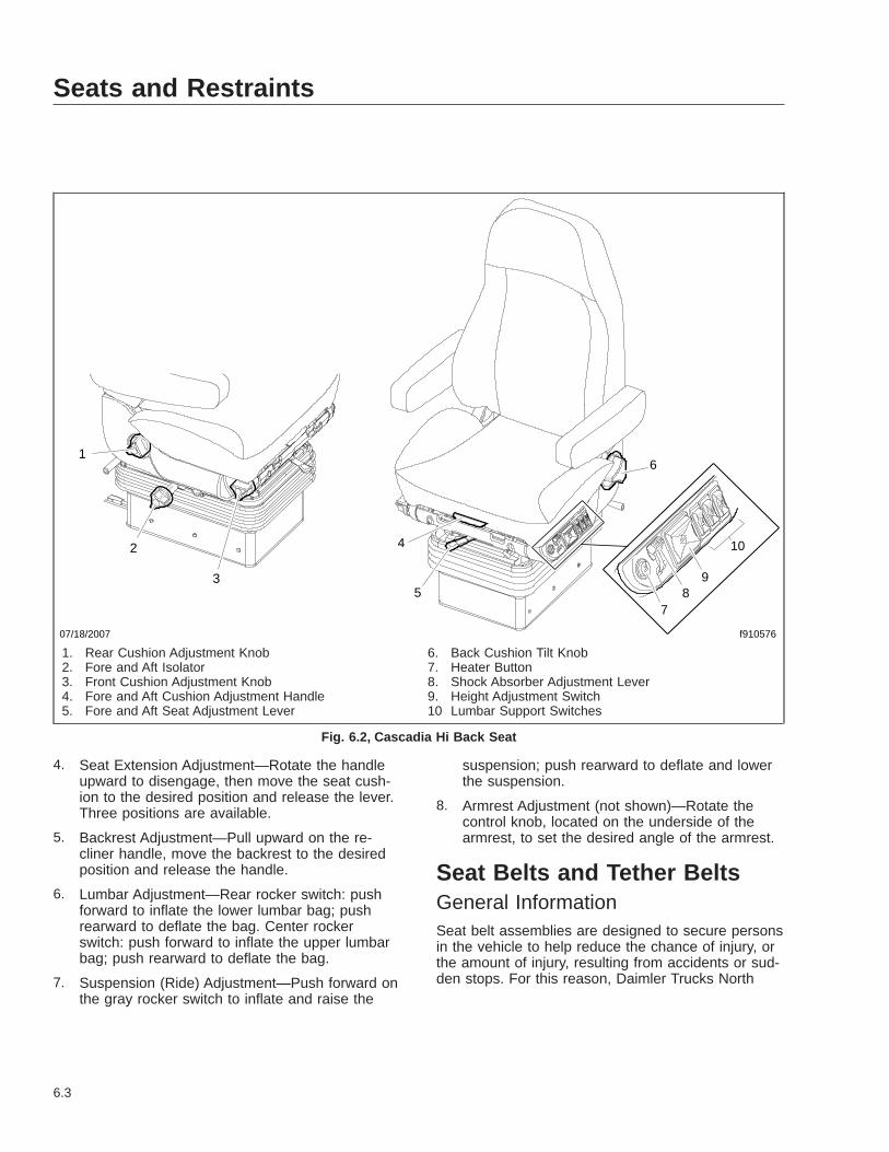
4. Seat Extension Adjustment—Rotate the handleupward to disengage, then move the seat cush-ion to the desired position and release the lever.Three positions are available.
5. Backrest Adjustment—Pull upward on the re-cliner handle, move the backrest to the desiredposition and release the handle.
6. Lumbar Adjustment—Rear rocker switch: pushforward to inflate the lower lumbar bag; pushrearward to deflate the bag. Center rockerswitch: push forward to inflate the upper lumbarbag; push rearward to deflate the bag.
7. Suspension (Ride) Adjustment—Push forward onthe gray rocker switch to inflate and raise the
suspension; push rearward to deflate and lowerthe suspension.
8. Armrest Adjustment (not shown)—Rotate thecontrol knob, located on the underside of thearmrest, to set the desired angle of the armrest.
Seat Belts and Tether BeltsGeneral InformationSeat belt assemblies are designed to secure personsin the vehicle to help reduce the chance of injury, orthe amount of injury, resulting from accidents or sud-den stops. For this reason, Daimler Trucks North
f910576
5
4
78
9
10
6
07/18/2007
1
2
3
1. Rear Cushion Adjustment Knob2. Fore and Aft Isolator3. Front Cushion Adjustment Knob4. Fore and Aft Cushion Adjustment Handle5. Fore and Aft Seat Adjustment Lever
6. Back Cushion Tilt Knob7. Heater Button8. Shock Absorber Adjustment Lever9. Height Adjustment Switch10 Lumbar Support Switches
Fig. 6.2, Cascadia Hi Back Seat
Seats and Restraints
6.3
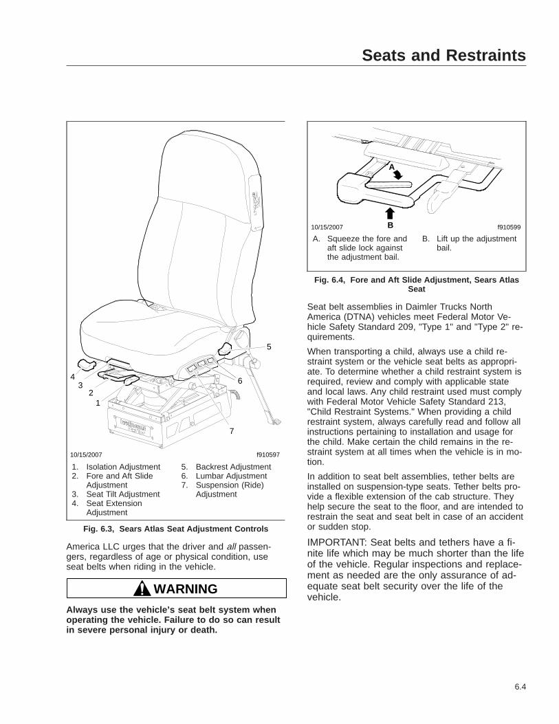
America LLC urges that the driver and all passen-gers, regardless of age or physical condition, useseat belts when riding in the vehicle.
WARNINGAlways use the vehicle’s seat belt system whenoperating the vehicle. Failure to do so can resultin severe personal injury or death.
Seat belt assemblies in Daimler Trucks NorthAmerica (DTNA) vehicles meet Federal Motor Ve-hicle Safety Standard 209, "Type 1" and "Type 2" re-quirements.
When transporting a child, always use a child re-straint system or the vehicle seat belts as appropri-ate. To determine whether a child restraint system isrequired, review and comply with applicable stateand local laws. Any child restraint used must complywith Federal Motor Vehicle Safety Standard 213,"Child Restraint Systems." When providing a childrestraint system, always carefully read and follow allinstructions pertaining to installation and usage forthe child. Make certain the child remains in the re-straint system at all times when the vehicle is in mo-tion.
In addition to seat belt assemblies, tether belts areinstalled on suspension-type seats. Tether belts pro-vide a flexible extension of the cab structure. Theyhelp secure the seat to the floor, and are intended torestrain the seat and seat belt in case of an accidentor sudden stop.
IMPORTANT: Seat belts and tethers have a fi-nite life which may be much shorter than the lifeof the vehicle. Regular inspections and replace-ment as needed are the only assurance of ad-equate seat belt security over the life of thevehicle.
10/15/2007 f910597
12
34
5
6
7
1. Isolation Adjustment2. Fore and Aft Slide
Adjustment3. Seat Tilt Adjustment4. Seat Extension
Adjustment
5. Backrest Adjustment6. Lumbar Adjustment7. Suspension (Ride)
Adjustment
Fig. 6.3, Sears Atlas Seat Adjustment Controls
10/15/2007 f910599
A
B
A. Squeeze the fore andaft slide lock againstthe adjustment bail.
B. Lift up the adjustmentbail.
Fig. 6.4, Fore and Aft Slide Adjustment, Sears AtlasSeat
Seats and Restraints
6.4
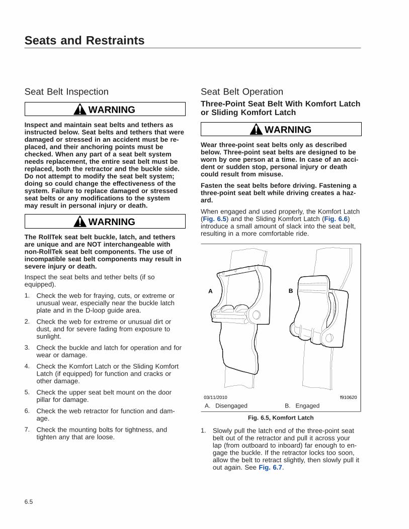
Seat Belt Inspection
WARNINGInspect and maintain seat belts and tethers asinstructed below. Seat belts and tethers that weredamaged or stressed in an accident must be re-placed, and their anchoring points must bechecked. When any part of a seat belt systemneeds replacement, the entire seat belt must bereplaced, both the retractor and the buckle side.Do not attempt to modify the seat belt system;doing so could change the effectiveness of thesystem. Failure to replace damaged or stressedseat belts or any modifications to the systemmay result in personal injury or death.
WARNINGThe RollTek seat belt buckle, latch, and tethersare unique and are NOT interchangeable withnon-RollTek seat belt components. The use ofincompatible seat belt components may result insevere injury or death.
Inspect the seat belts and tether belts (if soequipped).
1. Check the web for fraying, cuts, or extreme orunusual wear, especially near the buckle latchplate and in the D-loop guide area.
2. Check the web for extreme or unusual dirt ordust, and for severe fading from exposure tosunlight.
3. Check the buckle and latch for operation and forwear or damage.
4. Check the Komfort Latch or the Sliding KomfortLatch (if equipped) for function and cracks orother damage.
5. Check the upper seat belt mount on the doorpillar for damage.
6. Check the web retractor for function and dam-age.
7. Check the mounting bolts for tightness, andtighten any that are loose.
Seat Belt OperationThree-Point Seat Belt With Komfort Latchor Sliding Komfort Latch
WARNINGWear three-point seat belts only as describedbelow. Three-point seat belts are designed to beworn by one person at a time. In case of an acci-dent or sudden stop, personal injury or deathcould result from misuse.
Fasten the seat belts before driving. Fastening athree-point seat belt while driving creates a haz-ard.
When engaged and used properly, the Komfort Latch(Fig. 6.5 ) and the Sliding Komfort Latch (Fig. 6.6 )introduce a small amount of slack into the seat belt,resulting in a more comfortable ride.
1. Slowly pull the latch end of the three-point seatbelt out of the retractor and pull it across yourlap (from outboard to inboard) far enough to en-gage the buckle. If the retractor locks too soon,allow the belt to retract slightly, then slowly pull itout again. See Fig. 6.7 .
03/11/2010 f910620
A B
A. Disengaged B. Engaged
Fig. 6.5, Komfort Latch
Seats and Restraints
6.5
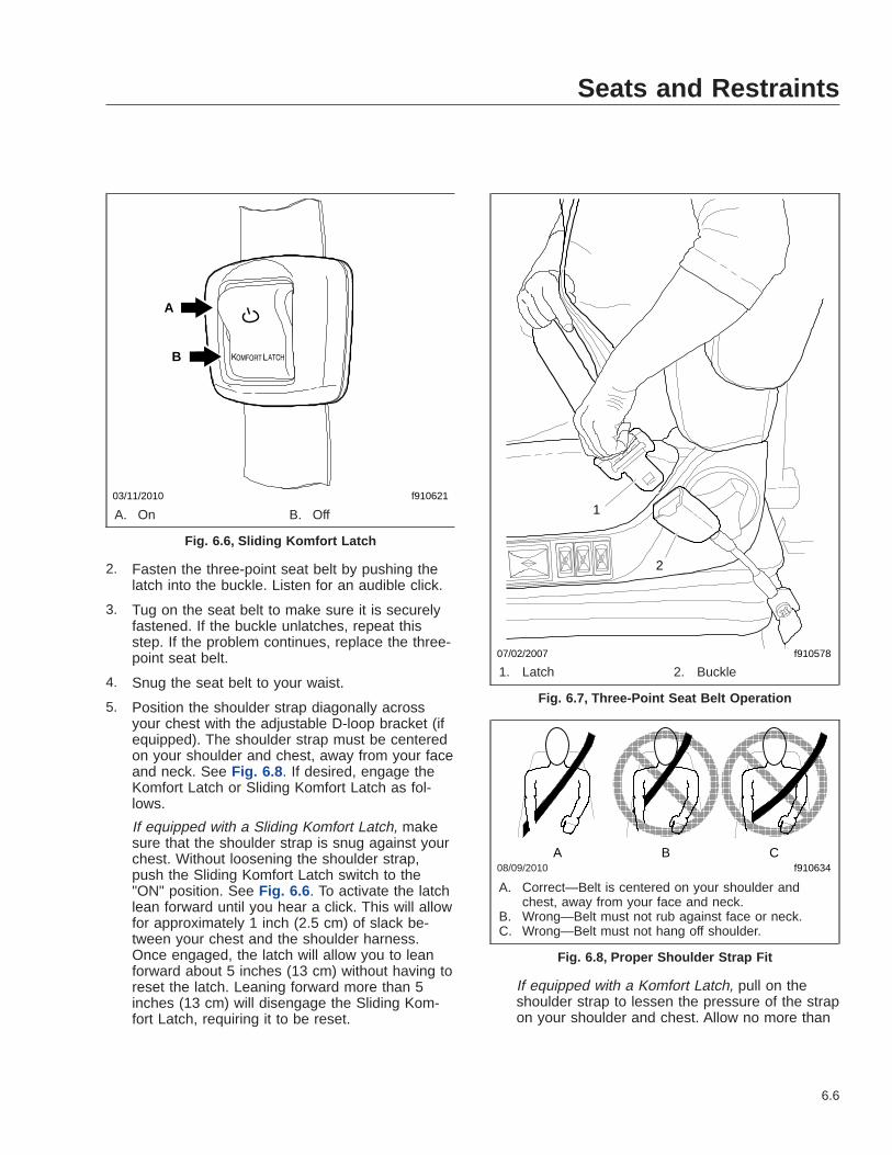
2. Fasten the three-point seat belt by pushing thelatch into the buckle. Listen for an audible click.
3. Tug on the seat belt to make sure it is securelyfastened. If the buckle unlatches, repeat thisstep. If the problem continues, replace the three-point seat belt.
4. Snug the seat belt to your waist.
5. Position the shoulder strap diagonally acrossyour chest with the adjustable D-loop bracket (ifequipped). The shoulder strap must be centeredon your shoulder and chest, away from your faceand neck. See Fig. 6.8 . If desired, engage theKomfort Latch or Sliding Komfort Latch as fol-lows.
If equipped with a Sliding Komfort Latch, makesure that the shoulder strap is snug against yourchest. Without loosening the shoulder strap,push the Sliding Komfort Latch switch to the"ON" position. See Fig. 6.6 . To activate the latchlean forward until you hear a click. This will allowfor approximately 1 inch (2.5 cm) of slack be-tween your chest and the shoulder harness.Once engaged, the latch will allow you to leanforward about 5 inches (13 cm) without having toreset the latch. Leaning forward more than 5inches (13 cm) will disengage the Sliding Kom-fort Latch, requiring it to be reset.
If equipped with a Komfort Latch, pull on theshoulder strap to lessen the pressure of the strapon your shoulder and chest. Allow no more than
03/11/2010 f910621
A
B
A. On B. Off
Fig. 6.6, Sliding Komfort Latch
07/02/2007 f910578
1
2
1. Latch 2. Buckle
Fig. 6.7, Three-Point Seat Belt Operation
08/09/2010 f910634A B C
A. Correct—Belt is centered on your shoulder andchest, away from your face and neck.
B. Wrong—Belt must not rub against face or neck.C. Wrong—Belt must not hang off shoulder.
Fig. 6.8, Proper Shoulder Strap Fit
Seats and Restraints
6.6
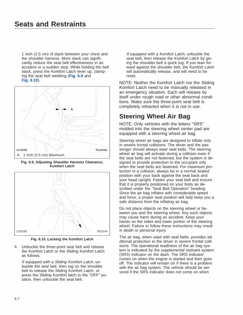
1 inch (2.5 cm) of slack between your chest andthe shoulder harness. More slack can signifi-cantly reduce the seat belt effectiveness in anaccident or a sudden stop. While holding the beltslack, press the Komfort Latch lever up, clamp-ing the seat belt webbing (Fig. 6.9 andFig. 6.10 ).
6. Unbuckle the three-point seat belt and releasethe Komfort Latch or the Sliding Komfort Latchas follows.
If equipped with a Sliding Komfort Latch, un-buckle the seat belt, then tug on the shoulderbelt to release the Sliding Komfort Latch, orpress the Sliding Komfort latch to the "OFF" po-sition, then unbuckle the seat belt.
If equipped with a Komfort Latch, unbuckle theseat belt, then release the Komfort Latch by giv-ing the shoulder belt a quick tug. If you lean for-ward against the shoulder belt, the Komfort Latchwill automatically release, and will need to bereset.
NOTE: Neither the Komfort Latch nor the SlidingKomfort Latch need to be manually released inan emergency situation. Each will release byitself under rough road or other abnormal condi-tions. Make sure the three-point seat belt iscompletely retracted when it is not in use.
Steering Wheel Air BagNOTE: Only vehicles with the letters "SRS"molded into the steering wheel center pad areequipped with a steering wheel air bag.
Steering wheel air bags are designed to inflate onlyin severe frontal collisions. The driver and the pas-senger should always wear seat belts. The steeringwheel air bag will activate during a collision even ifthe seat belts are not fastened, but the system is de-signed to provide protection to the occupant onlywhen the seat belts are fastened. For maximum pro-tection in a collision, always be in a normal seatedposition with your back against the seat back andyour head upright. Fasten your seat belt and ensurethat it is properly positioned on your body as de-scribed under the "Seat Belt Operation" heading.Since the air bag inflates with considerable speedand force, a proper seat position will help keep you asafe distance from the inflating air bag.
Do not place objects on the steering wheel or be-tween you and the steering wheel. Any such objectsmay cause harm during an accident. Keep yourhands on the sides and lower portion of the steeringwheel. Failure to follow these instructions may resultin death or personal injury.
The air bag, when used with seat belts, provides ad-ditional protection to the driver in severe frontal colli-sions. The operational readiness of the air bag sys-tem is indicated by the supplemental restraint system(SRS) indicator on the dash. The SRS indicatorcomes on when the engine is started and then goesoff. The indicator will remain on if there is a problemwith the air bag system. The vehicle should be ser-viced if the SRS indicator does not come on when
A
01/06/95 f910048a
A. 1 Inch (2.5 cm) Maximum
Fig. 6.9, Adjusting Shoulder Harness Clearance,Komfort Latch
11/02/95 f910144
Fig. 6.10, Locking the Komfort Latch
Seats and Restraints
6.7
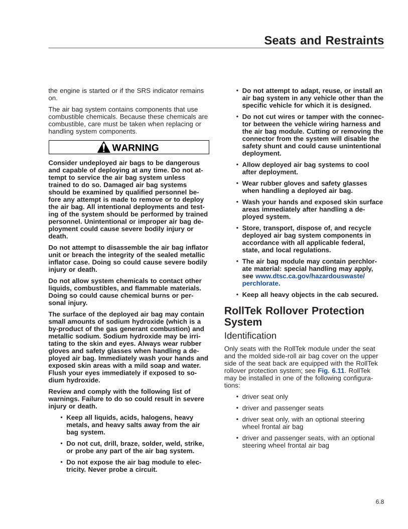
the engine is started or if the SRS indicator remainson.
The air bag system contains components that usecombustible chemicals. Because these chemicals arecombustible, care must be taken when replacing orhandling system components.
WARNINGConsider undeployed air bags to be dangerousand capable of deploying at any time. Do not at-tempt to service the air bag system unlesstrained to do so. Damaged air bag systemsshould be examined by qualified personnel be-fore any attempt is made to remove or to deploythe air bag. All intentional deployments and test-ing of the system should be performed by trainedpersonnel. Unintentional or improper air bag de-ployment could cause severe bodily injury ordeath.
Do not attempt to disassemble the air bag inflatorunit or breach the integrity of the sealed metallicinflator case. Doing so could cause severe bodilyinjury or death.
Do not allow system chemicals to contact otherliquids, combustibles, and flammable materials.Doing so could cause chemical burns or per-sonal injury.
The surface of the deployed air bag may containsmall amounts of sodium hydroxide (which is aby-product of the gas generant combustion) andmetallic sodium. Sodium hydroxide may be irri-tating to the skin and eyes. Always wear rubbergloves and safety glasses when handling a de-ployed air bag. Immediately wash your hands andexposed skin areas with a mild soap and water.Flush your eyes immediately if exposed to so-dium hydroxide.
Review and comply with the following list ofwarnings. Failure to do so could result in severeinjury or death.
• Keep all liquids, acids, halogens, heavymetals, and heavy salts away from the airbag system.
• Do not cut, drill, braze, solder, weld, strike,or probe any part of the air bag system.
• Do not expose the air bag module to elec-tricity. Never probe a circuit.
• Do not attempt to adapt, reuse, or install anair bag system in any vehicle other than thespecific vehicle for which it is designed.
• Do not cut wires or tamper with the connec-tor between the vehicle wiring harness andthe air bag module. Cutting or removing theconnector from the system will disable thesafety shunt and could cause unintentionaldeployment.
• Allow deployed air bag systems to coolafter deployment.
• Wear rubber gloves and safety glasseswhen handling a deployed air bag.
• Wash your hands and exposed skin surfaceareas immediately after handling a de-ployed system.
• Store, transport, dispose of, and recycledeployed air bag system components inaccordance with all applicable federal,state, and local regulations.
• The air bag module may contain perchlor-ate material: special handling may apply,see www.dtsc.ca.gov/hazardouswaste/perchlorate .
• Keep all heavy objects in the cab secured.
RollTek Rollover ProtectionSystemIdentificationOnly seats with the RollTek module under the seatand the molded side-roll air bag cover on the upperside of the seat back are equipped with the RollTekrollover protection system; see Fig. 6.11 . RollTekmay be installed in one of the following configura-tions:
• driver seat only
• driver and passenger seats
• driver seat only, with an optional steeringwheel frontal air bag
• driver and passenger seats, with an optionalsteering wheel frontal air bag
Seats and Restraints
6.8
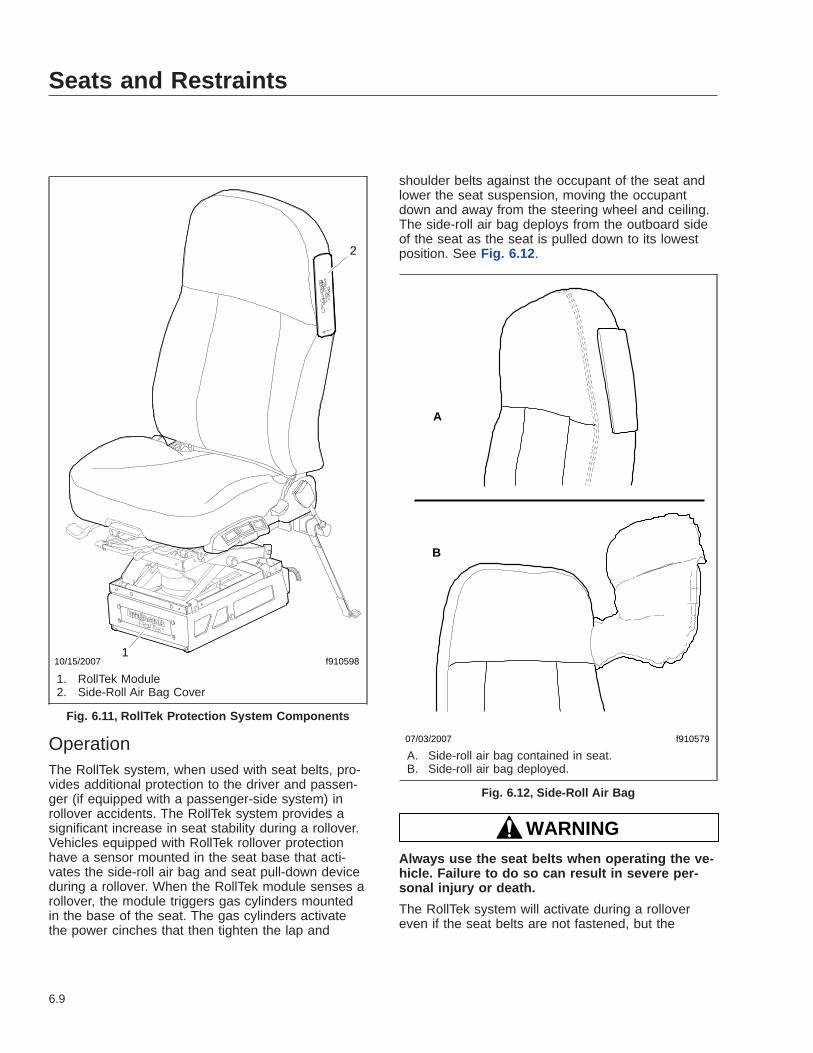
OperationThe RollTek system, when used with seat belts, pro-vides additional protection to the driver and passen-ger (if equipped with a passenger-side system) inrollover accidents. The RollTek system provides asignificant increase in seat stability during a rollover.Vehicles equipped with RollTek rollover protectionhave a sensor mounted in the seat base that acti-vates the side-roll air bag and seat pull-down deviceduring a rollover. When the RollTek module senses arollover, the module triggers gas cylinders mountedin the base of the seat. The gas cylinders activatethe power cinches that then tighten the lap and
shoulder belts against the occupant of the seat andlower the seat suspension, moving the occupantdown and away from the steering wheel and ceiling.The side-roll air bag deploys from the outboard sideof the seat as the seat is pulled down to its lowestposition. See Fig. 6.12 .
WARNINGAlways use the seat belts when operating the ve-hicle. Failure to do so can result in severe per-sonal injury or death.
The RollTek system will activate during a rollovereven if the seat belts are not fastened, but the
10/15/2007 f9105981
2
1. RollTek Module2. Side-Roll Air Bag Cover
Fig. 6.11, RollTek Protection System Components
07/03/2007
A
B
f910579
A. Side-roll air bag contained in seat.B. Side-roll air bag deployed.
Fig. 6.12, Side-Roll Air Bag
Seats and Restraints
6.9
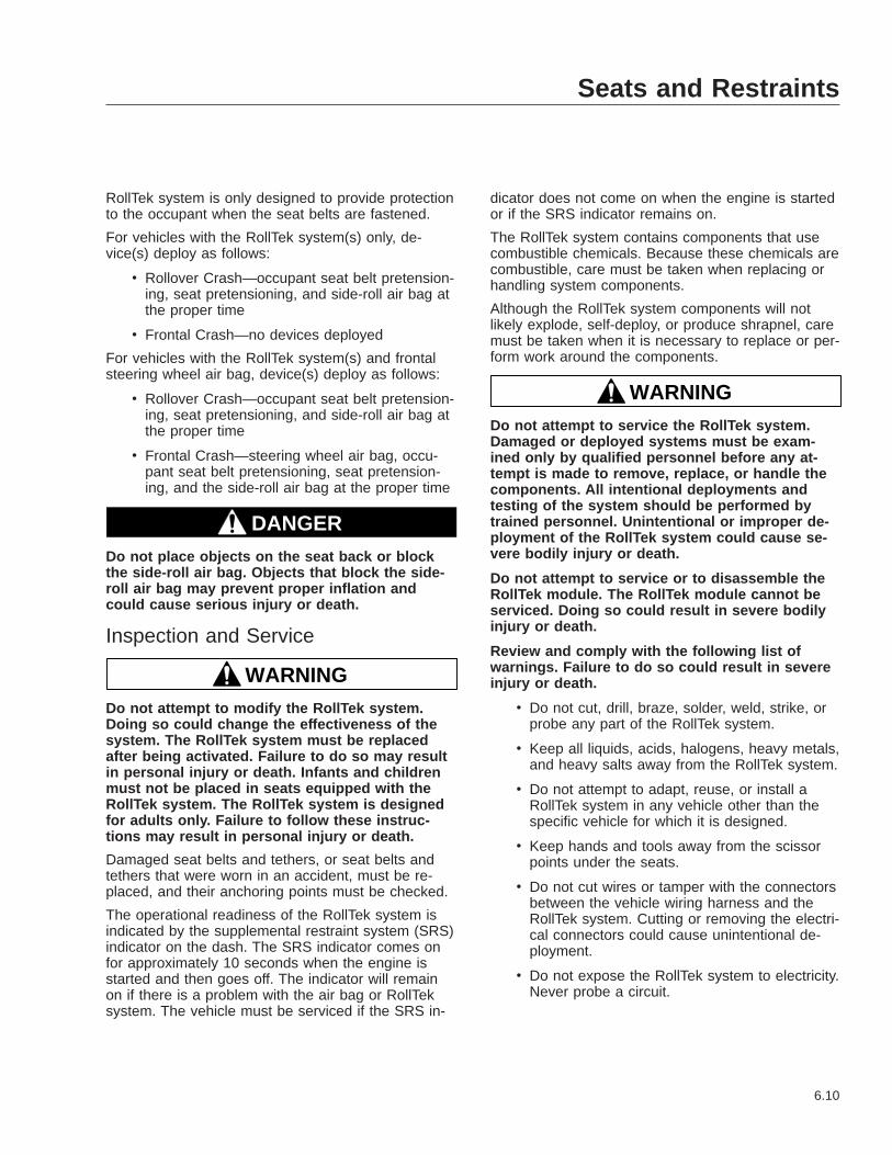
RollTek system is only designed to provide protectionto the occupant when the seat belts are fastened.
For vehicles with the RollTek system(s) only, de-vice(s) deploy as follows:
• Rollover Crash—occupant seat belt pretension-ing, seat pretensioning, and side-roll air bag atthe proper time
• Frontal Crash—no devices deployed
For vehicles with the RollTek system(s) and frontalsteering wheel air bag, device(s) deploy as follows:
• Rollover Crash—occupant seat belt pretension-ing, seat pretensioning, and side-roll air bag atthe proper time
• Frontal Crash—steering wheel air bag, occu-pant seat belt pretensioning, seat pretension-ing, and the side-roll air bag at the proper time
DANGERDo not place objects on the seat back or blockthe side-roll air bag. Objects that block the side-roll air bag may prevent proper inflation andcould cause serious injury or death.
Inspection and Service
WARNINGDo not attempt to modify the RollTek system.Doing so could change the effectiveness of thesystem. The RollTek system must be replacedafter being activated. Failure to do so may resultin personal injury or death. Infants and childrenmust not be placed in seats equipped with theRollTek system. The RollTek system is designedfor adults only. Failure to follow these instruc-tions may result in personal injury or death.
Damaged seat belts and tethers, or seat belts andtethers that were worn in an accident, must be re-placed, and their anchoring points must be checked.
The operational readiness of the RollTek system isindicated by the supplemental restraint system (SRS)indicator on the dash. The SRS indicator comes onfor approximately 10 seconds when the engine isstarted and then goes off. The indicator will remainon if there is a problem with the air bag or RollTeksystem. The vehicle must be serviced if the SRS in-
dicator does not come on when the engine is startedor if the SRS indicator remains on.
The RollTek system contains components that usecombustible chemicals. Because these chemicals arecombustible, care must be taken when replacing orhandling system components.
Although the RollTek system components will notlikely explode, self-deploy, or produce shrapnel, caremust be taken when it is necessary to replace or per-form work around the components.
WARNINGDo not attempt to service the RollTek system.Damaged or deployed systems must be exam-ined only by qualified personnel before any at-tempt is made to remove, replace, or handle thecomponents. All intentional deployments andtesting of the system should be performed bytrained personnel. Unintentional or improper de-ployment of the RollTek system could cause se-vere bodily injury or death.
Do not attempt to service or to disassemble theRollTek module. The RollTek module cannot beserviced. Doing so could result in severe bodilyinjury or death.
Review and comply with the following list ofwarnings. Failure to do so could result in severeinjury or death.
• Do not cut, drill, braze, solder, weld, strike, orprobe any part of the RollTek system.
• Keep all liquids, acids, halogens, heavy metals,and heavy salts away from the RollTek system.
• Do not attempt to adapt, reuse, or install aRollTek system in any vehicle other than thespecific vehicle for which it is designed.
• Keep hands and tools away from the scissorpoints under the seats.
• Do not cut wires or tamper with the connectorsbetween the vehicle wiring harness and theRollTek system. Cutting or removing the electri-cal connectors could cause unintentional de-ployment.
• Do not expose the RollTek system to electricity.Never probe a circuit.
Seats and Restraints
6.10
• Store, transport, dispose of, and recycle de-ployed RollTek system components in accor-dance with all applicable federal, state, andlocal regulations.
• Replace damaged seat belts or seat belts thatwere worn in an accident, and check all an-choring points. Only qualified personnel familiarwith RollTek systems should replace the seatbelts used in a vehicle with a RollTek system.
• The RollTek system requires a special seatbelt. Care must be taken to be sure the correctseat belt is used.
• Keep all heavy objects in the cab secured.
The frontal air bag (crash) sensor, included with thesteering wheel air bag system, will only deploy de-vice(s) in the event of a significant impact from afrontal crash.
Seats and Restraints
6.11
7
Climate ControlCab Climate Control . . . . . . . . . . . . . . . . . . . . . . . . . . . . . . . . . . . . . . . . . . . . . . . . . . . . . . . . . . . . . . . 7.1Sleeper Climate Control . . . . . . . . . . . . . . . . . . . . . . . . . . . . . . . . . . . . . . . . . . . . . . . . . . . . . . . . . . . . 7.3ParkSmart Auxiliary HVAC . . . . . . . . . . . . . . . . . . . . . . . . . . . . . . . . . . . . . . . . . . . . . . . . . . . . . . . . . . 7.4
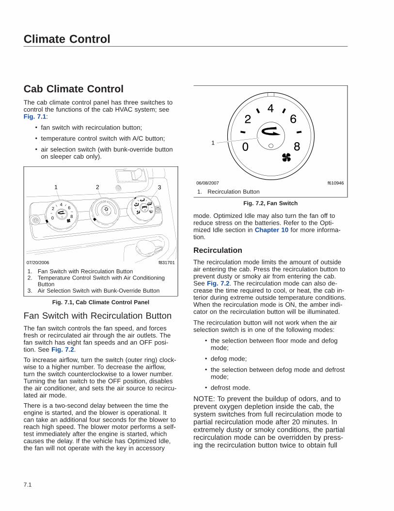
Cab Climate ControlThe cab climate control panel has three switches tocontrol the functions of the cab HVAC system; seeFig. 7.1 :
• fan switch with recirculation button;
• temperature control switch with A/C button;
• air selection switch (with bunk-override buttonon sleeper cab only).
Fan Switch with Recirculation ButtonThe fan switch controls the fan speed, and forcesfresh or recirculated air through the air outlets. Thefan switch has eight fan speeds and an OFF posi-tion. See Fig. 7.2 .
To increase airflow, turn the switch (outer ring) clock-wise to a higher number. To decrease the airflow,turn the switch counterclockwise to a lower number.Turning the fan switch to the OFF position, disablesthe air conditioner, and sets the air source to recircu-lated air mode.
There is a two-second delay between the time theengine is started, and the blower is operational. Itcan take an additional four seconds for the blower toreach high speed. The blower motor performs a self-test immediately after the engine is started, whichcauses the delay. If the vehicle has Optimized Idle,the fan will not operate with the key in accessory
mode. Optimized Idle may also turn the fan off toreduce stress on the batteries. Refer to the Opti-mized Idle section in Chapter 10 for more informa-tion.
RecirculationThe recirculation mode limits the amount of outsideair entering the cab. Press the recirculation button toprevent dusty or smoky air from entering the cab.See Fig. 7.2 . The recirculation mode can also de-crease the time required to cool, or heat, the cab in-terior during extreme outside temperature conditions.When the recirculation mode is ON, the amber indi-cator on the recirculation button will be illuminated.
The recirculation button will not work when the airselection switch is in one of the following modes:
• the selection between floor mode and defogmode;
• defog mode;
• the selection between defog mode and defrostmode;
• defrost mode.
NOTE: To prevent the buildup of odors, and toprevent oxygen depletion inside the cab, thesystem switches from full recirculation mode topartial recirculation mode after 20 minutes. Inextremely dusty or smoky conditions, the partialrecirculation mode can be overridden by press-ing the recirculation button twice to obtain full
0
24
8
6
07/20/2006 f831701
1 2 3
1. Fan Switch with Recirculation Button2. Temperature Control Switch with Air Conditioning
Button3. Air Selection Switch with Bunk-Override Button
Fig. 7.1, Cab Climate Control Panel
06/08/2007 f610946
1
1. Recirculation Button
Fig. 7.2, Fan Switch
Climate Control
7.1
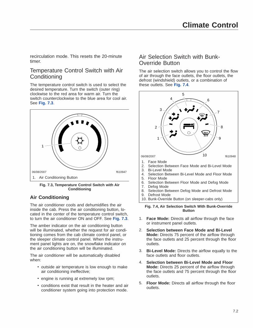
recirculation mode. This resets the 20-minutetimer.
Temperature Control Switch with AirConditioningThe temperature control switch is used to select thedesired temperature. Turn the switch (outer ring)clockwise to the red area for warm air. Turn theswitch counterclockwise to the blue area for cool air.See Fig. 7.3 .
Air ConditioningThe air conditioner cools and dehumidifies the airinside the cab. Press the air conditioning button, lo-cated in the center of the temperature control switch,to turn the air conditioner ON and OFF. See Fig. 7.3 .
The amber indicator on the air conditioning buttonwill be illuminated, whether the request for air condi-tioning comes from the cab climate control panel, orthe sleeper climate control panel. When the instru-ment panel lights are on, the snowflake indicator onthe air conditioning button will be illuminated.
The air conditioner will be automatically disabledwhen:
• outside air temperature is low enough to makeair conditioning ineffective;
• engine is running at extremely low rpm;
• conditions exist that result in the heater and airconditioner system going into protection mode.
Air Selection Switch with Bunk-Override ButtonThe air selection switch allows you to control the flowof air through the face outlets, the floor outlets, thedefrost (windshield) outlets, or a combination ofthese outlets. See Fig. 7.4 .
1. Face Mode: Directs all airflow through the faceor instrument panel outlets.
2. Selection between Face Mode and Bi-LevelMode: Directs 75 percent of the airflow throughthe face outlets and 25 percent through the flooroutlets.
3. Bi-Level Mode: Directs the airflow equally to theface outlets and floor outlets.
4. Selection between Bi-Level Mode and FloorMode: Directs 25 percent of the airflow throughthe face outlets and 75 percent through the flooroutlets.
5. Floor Mode: Directs all airflow through the flooroutlets.
06/08/2007 f610947
1
1. Air Conditioning Button
Fig. 7.3, Temperature Control Switch with AirConditioning
06/08/2007 f610948
1
2
3
45
6
7
8
9
10
1. Face Mode2. Selection Between Face Mode and Bi-Level Mode3. Bi-Level Mode4. Selection Between Bi-Level Mode and Floor Mode5. Floor Mode6. Selection Between Floor Mode and Defog Mode7. Defog Mode8. Selection Between Defog Mode and Defrost Mode9. Defrost Mode10. Bunk-Override Button (on sleeper-cabs only)
Fig. 7.4, Air Selection Switch With Bunk-OverrideButton
Climate Control
7.2
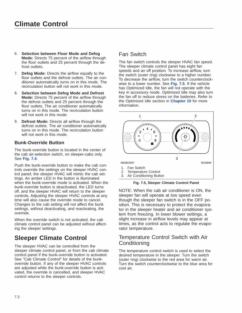
6. Selection between Floor Mode and DefogMode: Directs 75 percent of the airflow throughthe floor outlets and 25 percent through the de-frost outlets.
7. Defog Mode: Directs the airflow equally to thefloor outlets and the defrost outlets. The air con-ditioner automatically turns on in this mode. Therecirculation button will not work in this mode.
8. Selection between Defog Mode and DefrostMode: Directs 75 percent of the airflow throughthe defrost outlets and 25 percent through thefloor outlets. The air conditioner automaticallyturns on in this mode. The recirculation buttonwill not work in this mode.
9. Defrost Mode: Directs all airflow through thedefrost outlets. The air conditioner automaticallyturns on in this mode. The recirculation buttonwill not work in this mode.
Bunk-Override ButtonThe bunk-override button is located in the center ofthe cab air-selection switch, on sleeper-cabs only.See Fig. 7.4 .
Push the bunk-override button to make the cab con-trols override the settings on the sleeper HVAC con-trol panel; the sleeper HVAC will mimic the cab set-tings. An amber LED in the button is illuminatedwhen the bunk-override mode is activated. When thebunk-override button is deactivated, the LED turnsoff, and the sleeper HVAC will return to the sleepercontrols. Adjusting the sleeper HVAC controls at anytime will also cause the override mode to cancel.Changes to the cab setting will not affect the bunksettings, without deactivating, and reactivating, theoverride.
When the override switch is not activated, the cabclimate control panel can be adjusted without affect-ing the sleeper settings.
Sleeper Climate ControlThe sleeper HVAC can be controlled from thesleeper climate control panel, or from the cab climatecontrol panel if the bunk-override button is activated.See "Cab Climate Control" for details of the bunk-override button. If any of the sleeper HVAC controlsare adjusted while the bunk-override button is acti-vated, the override is cancelled, and sleeper HVACcontrol returns to the sleeper controls.
Fan SwitchThe fan switch controls the sleeper HVAC fan speed.The sleeper climate control panel has eight fanspeeds and an off position. To increase airflow, turnthe switch (outer ring) clockwise to a higher number.To decrease the airflow, turn the switch counterclock-wise to a lower number. See Fig. 7.5 . If the vehiclehas Optimized Idle, the fan will not operate with thekey in accessory mode. Optimized Idle may also turnthe fan off to reduce stress on the batteries. Refer tothe Optimized Idle section in Chapter 10 for moreinformation.
NOTE: When the cab air conditioner is ON, thesleeper fan will operate at low speed eventhough the sleeper fan switch is in the OFF po-sition. This is necessary to protect the evapora-tor in the sleeper heater and air conditioner sys-tem from freezing. In lower blower settings, aslight increase in airflow levels may appear attimes, as the control acts to regulate the evapo-rator temperature.
Temperature Control Switch with AirConditioningThe temperature control switch is used to select thedesired temperature in the sleeper. Turn the switch(outer ring) clockwise to the red area for warm air.Turn the switch counterclockwise to the blue area forcool air.
06/08/2007 f610949
1 2
3
1. Fan Switch2. Temperature Control3. Air Conditioning Button
Fig. 7.5, Sleeper Climate Control Panel
Climate Control
7.3
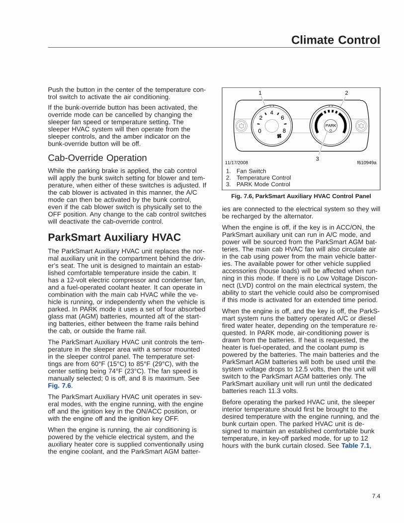
Push the button in the center of the temperature con-trol switch to activate the air conditioning.
If the bunk-override button has been activated, theoverride mode can be cancelled by changing thesleeper fan speed or temperature setting. Thesleeper HVAC system will then operate from thesleeper controls, and the amber indicator on thebunk-override button will be off.
Cab-Override OperationWhile the parking brake is applied, the cab controlwill apply the bunk switch setting for blower and tem-perature, when either of these switches is adjusted. Ifthe cab blower is activated in this manner, the A/Cmode can then be activated by the bunk control,even if the cab blower switch is physically set to theOFF position. Any change to the cab control switcheswill deactivate the cab-override control.
ParkSmart Auxiliary HVACThe ParkSmart Auxiliary HVAC unit replaces the nor-mal auxiliary unit in the compartment behind the driv-er’s seat. The unit is designed to maintain an estab-lished comfortable temperature inside the cabin. Ithas a 12-volt electric compressor and condenser fan,and a fuel-operated coolant heater. It can operate incombination with the main cab HVAC while the ve-hicle is running, or independently when the vehicle isparked. In PARK mode it uses a set of four absorbedglass mat (AGM) batteries, mounted aft of the start-ing batteries, either between the frame rails behindthe cab, or outside the frame rail.
The ParkSmart Auxiliary HVAC unit controls the tem-perature in the sleeper area with a sensor mountedin the sleeper control panel. The temperature set-tings are from 60°F (15°C) to 85°F (29°C), with thecenter setting being 74°F (23°C). The fan speed ismanually selected; 0 is off, and 8 is maximum. SeeFig. 7.6 .
The ParkSmart Auxiliary HVAC unit operates in sev-eral modes, with the engine running, with the engineoff and the ignition key in the ON/ACC position, orwith the engine off and the ignition key OFF.
When the engine is running, the air conditioning ispowered by the vehicle electrical system, and theauxiliary heater core is supplied conventionally usingthe engine coolant, and the ParkSmart AGM batter-
ies are connected to the electrical system so they willbe recharged by the alternator.
When the engine is off, if the key is in ACC/ON, theParkSmart auxiliary unit can run in A/C mode, andpower will be sourced from the ParkSmart AGM bat-teries. The main cab HVAC fan will also circulate airin the cab using power from the main vehicle batter-ies. The available power for other vehicle suppliedaccessories (house loads) will be affected when run-ning in this mode. If there is no Low Voltage Discon-nect (LVD) control on the main electrical system, theability to start the vehicle could also be compromisedif this mode is activated for an extended time period.
When the engine is off, and the key is off, the ParkS-mart system runs the battery operated A/C or dieselfired water heater, depending on the temperature re-quested. In PARK mode, air-conditioning power isdrawn from the batteries. If heat is requested, theheater is fuel-operated, and the coolant pump ispowered by the batteries. The main batteries and theParkSmart AGM batteries will both be used until thesystem voltage drops to 12.5 volts, then the unit willswitch to the ParkSmart AGM batteries only. TheParkSmart auxiliary unit will run until the dedicatedbatteries reach 11.3 volts.
Before operating the parked HVAC unit, the sleeperinterior temperature should first be brought to thedesired temperature with the engine running, and thebunk curtain open. The parked HVAC unit is de-signed to maintain an established comfortable bunktemperature, in key-off parked mode, for up to 12hours with the bunk curtain closed. See Table 7.1 ,
f610949a
1 2
311/17/2008
1. Fan Switch2. Temperature Control3. PARK Mode Control
Fig. 7.6, ParkSmart Auxiliary HVAC Control Panel
Climate Control
7.4
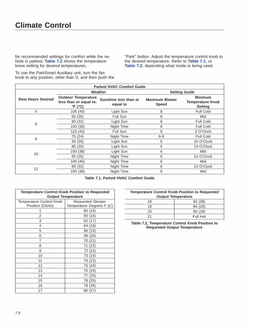
for recommended settings for comfort while the ve-hicle is parked. Table 7.2 shows the temperatureknow setting for desired temperatures.
To use the ParkSmart Auxiliary unit, turn the fanknob to any position, other than 0, and then push the
"Park" button. Adjust the temperature control knob tothe desired temperature. Refer to Table 7.1 , orTable 7.2 , depending what mode is being used.
Parked HVAC Comfort Guide
Rest Hours Desired
Weather Setting GuideOutdoor Temperatureless than or equal to:
°F (°C)
Sunshine less than orequal to
Maximum BlowerSpeed
MinimumTemperature Knob
Setting4 105 (40) Light Sun 8 Full Cold
6
95 (35) Full Sun 8 Mid90 (32) Light Sun 8 Full Cold
100 (38) Night Time 8 Full Cold110 (43) Full Sun 6 3 O’Clock
875 (24) Night Time 6-8 Full Cold95 (35) Light Sun 6 10 O’Clock
10
85 (30) Light Sun 6 10 O’Clock100 (38) Light Sun 6 Mid95 (35) Night Time 6 10 O’Clock
105 (40) Night Time 6 Mid
1290 (32) Night Time 6 10 O’Clock
100 (38) Night Time 6 Mid
Table 7.1, Parked HVAC Comfort Guide
Temperature Control Knob Position to RequestedOutput Temperature
Temperature Control KnobPosition (Clicks)
Requested SleeperTemperature Degrees F (C)
1 60 (16)2 60 (16)3 62 (17)4 64 (18)5 66 (19)6 68 (20)7 70 (21)8 71 (22)9 72 (22)10 73 (23)11 74 (23)12 75 (24)13 76 (24)14 77 (25)15 78 (25)16 79 (26)17 80 (27)
Temperature Control Knob Position to RequestedOutput Temperature
18 82 (38)19 84 (29)20 85 (29)21 Full Hot
Table 7.2, Temperature Control Knob Position toRequested Output Temperature
Climate Control
7.5
8
Cab FeaturesWindows . . . . . . . . . . . . . . . . . . . . . . . . . . . . . . . . . . . . . . . . . . . . . . . . . . . . . . . . . . . . . . . . . . . . . . . . 8.1Mirrors . . . . . . . . . . . . . . . . . . . . . . . . . . . . . . . . . . . . . . . . . . . . . . . . . . . . . . . . . . . . . . . . . . . . . . . . . . 8.1Cab Amenities . . . . . . . . . . . . . . . . . . . . . . . . . . . . . . . . . . . . . . . . . . . . . . . . . . . . . . . . . . . . . . . . . . . . 8.1Windshield Washer Reservoir . . . . . . . . . . . . . . . . . . . . . . . . . . . . . . . . . . . . . . . . . . . . . . . . . . . . . . . 8.2Horn Controls . . . . . . . . . . . . . . . . . . . . . . . . . . . . . . . . . . . . . . . . . . . . . . . . . . . . . . . . . . . . . . . . . . . . 8.2
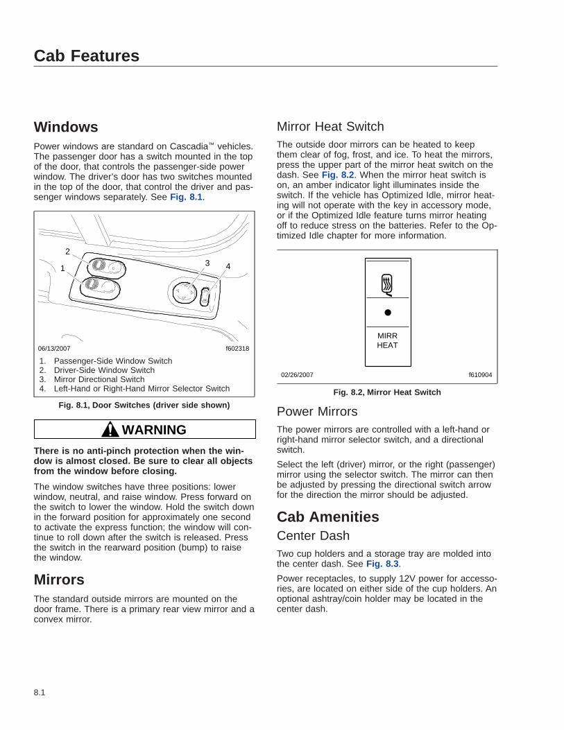
WindowsPower windows are standard on Cascadia™ vehicles.The passenger door has a switch mounted in the topof the door, that controls the passenger-side powerwindow. The driver’s door has two switches mountedin the top of the door, that control the driver and pas-senger windows separately. See Fig. 8.1 .
WARNINGThere is no anti-pinch protection when the win-dow is almost closed. Be sure to clear all objectsfrom the window before closing.
The window switches have three positions: lowerwindow, neutral, and raise window. Press forward onthe switch to lower the window. Hold the switch downin the forward position for approximately one secondto activate the express function; the window will con-tinue to roll down after the switch is released. Pressthe switch in the rearward position (bump) to raisethe window.
MirrorsThe standard outside mirrors are mounted on thedoor frame. There is a primary rear view mirror and aconvex mirror.
Mirror Heat SwitchThe outside door mirrors can be heated to keepthem clear of fog, frost, and ice. To heat the mirrors,press the upper part of the mirror heat switch on thedash. See Fig. 8.2 . When the mirror heat switch ison, an amber indicator light illuminates inside theswitch. If the vehicle has Optimized Idle, mirror heat-ing will not operate with the key in accessory mode,or if the Optimized Idle feature turns mirror heatingoff to reduce stress on the batteries. Refer to the Op-timized Idle chapter for more information.
Power MirrorsThe power mirrors are controlled with a left-hand orright-hand mirror selector switch, and a directionalswitch.
Select the left (driver) mirror, or the right (passenger)mirror using the selector switch. The mirror can thenbe adjusted by pressing the directional switch arrowfor the direction the mirror should be adjusted.
Cab AmenitiesCenter DashTwo cup holders and a storage tray are molded intothe center dash. See Fig. 8.3 .
Power receptacles, to supply 12V power for accesso-ries, are located on either side of the cup holders. Anoptional ashtray/coin holder may be located in thecenter dash.
06/13/2007 f602318
1
23 4
1. Passenger-Side Window Switch2. Driver-Side Window Switch3. Mirror Directional Switch4. Left-Hand or Right-Hand Mirror Selector Switch
Fig. 8.1, Door Switches (driver side shown)
MIRRHEAT
f61090402/26/2007
Fig. 8.2, Mirror Heat Switch
Cab Features
8.1
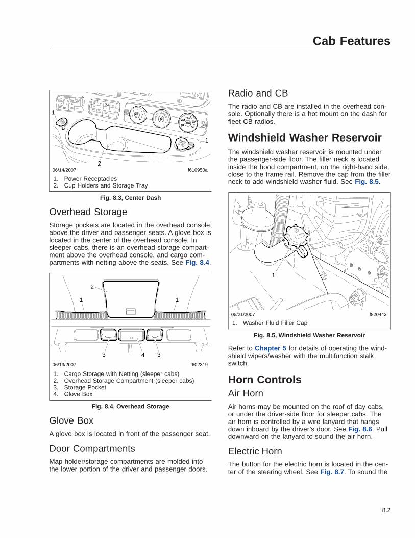
Overhead StorageStorage pockets are located in the overhead console,above the driver and passenger seats. A glove box islocated in the center of the overhead console. Insleeper cabs, there is an overhead storage compart-ment above the overhead console, and cargo com-partments with netting above the seats. See Fig. 8.4 .
Glove BoxA glove box is located in front of the passenger seat.
Door CompartmentsMap holder/storage compartments are molded intothe lower portion of the driver and passenger doors.
Radio and CBThe radio and CB are installed in the overhead con-sole. Optionally there is a hot mount on the dash forfleet CB radios.
Windshield Washer ReservoirThe windshield washer reservoir is mounted underthe passenger-side floor. The filler neck is locatedinside the hood compartment, on the right-hand side,close to the frame rail. Remove the cap from the fillerneck to add windshield washer fluid. See Fig. 8.5 .
Refer to Chapter 5 for details of operating the wind-shield wipers/washer with the multifunction stalkswitch.
Horn ControlsAir HornAir horns may be mounted on the roof of day cabs,or under the driver-side floor for sleeper cabs. Theair horn is controlled by a wire lanyard that hangsdown inboard by the driver’s door. See Fig. 8.6 . Pulldownward on the lanyard to sound the air horn.
Electric HornThe button for the electric horn is located in the cen-ter of the steering wheel. See Fig. 8.7 . To sound the
ENGSHDN ATC
ENGBRK
MIRRHEAT UTLY
LAMPDOME
HI
LO
0
2 4
8
6
POW
ER
OU
TLET
12V−10A
IS IN MOTION SUSPAIR
LOWERAUTO
POWEROUTLET12V−10A
TRLRAUX
OVRD TC
06/14/2007 f610950a2
1
1
1. Power Receptacles2. Cup Holders and Storage Tray
Fig. 8.3, Center Dash
06/13/2007 f602319
1 1
2
3 34
1. Cargo Storage with Netting (sleeper cabs)2. Overhead Storage Compartment (sleeper cabs)3. Storage Pocket4. Glove Box
Fig. 8.4, Overhead Storage
05/21/2007 f820442
1
1. Washer Fluid Filler Cap
Fig. 8.5, Windshield Washer Reservoir
Cab Features
8.2
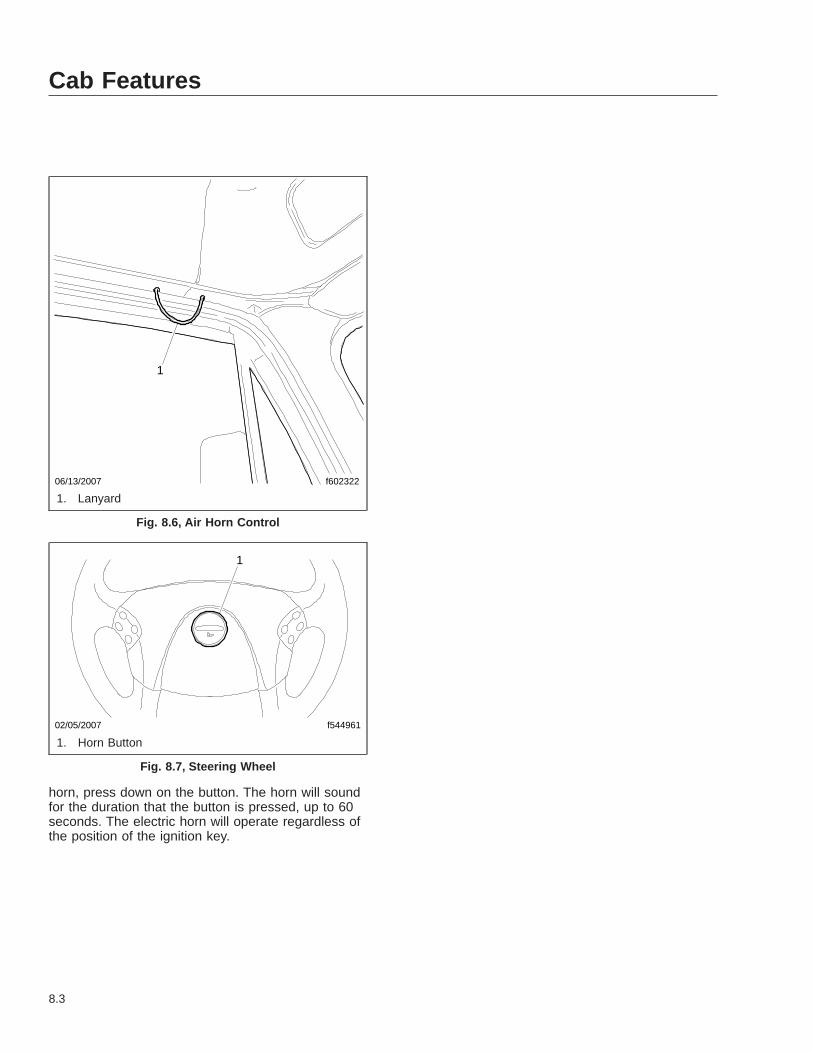
horn, press down on the button. The horn will soundfor the duration that the button is pressed, up to 60seconds. The electric horn will operate regardless ofthe position of the ignition key.
06/13/2007 f602322
1
1. Lanyard
Fig. 8.6, Air Horn Control
02/05/2007
1
f544961
1. Horn Button
Fig. 8.7, Steering Wheel
Cab Features
8.3
9
Engine Starting, Operation,and Shutdown
Engine Starting . . . . . . . . . . . . . . . . . . . . . . . . . . . . . . . . . . . . . . . . . . . . . . . . . . . . . . . . . . . . . . . . . . . 9.1Engine Operation . . . . . . . . . . . . . . . . . . . . . . . . . . . . . . . . . . . . . . . . . . . . . . . . . . . . . . . . . . . . . . . . . 9.2Engine Shutdown . . . . . . . . . . . . . . . . . . . . . . . . . . . . . . . . . . . . . . . . . . . . . . . . . . . . . . . . . . . . . . . . . 9.4
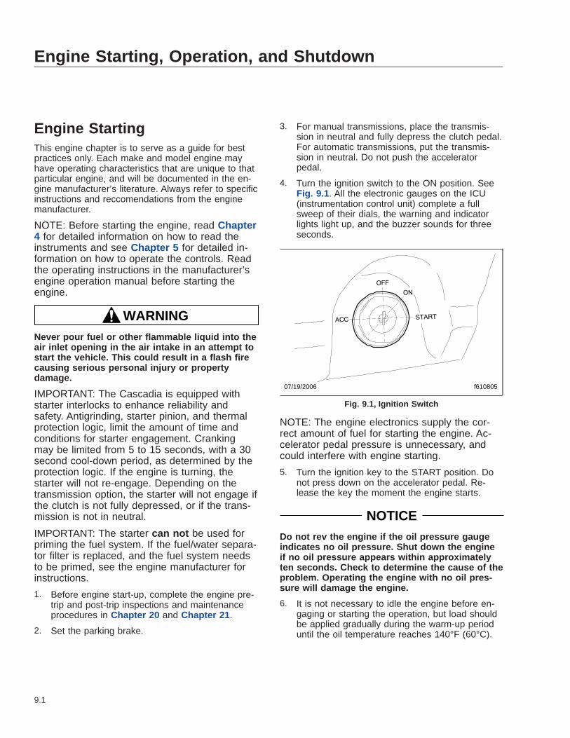
Engine StartingThis engine chapter is to serve as a guide for bestpractices only. Each make and model engine mayhave operating characteristics that are unique to thatparticular engine, and will be documented in the en-gine manufacturer’s literature. Always refer to specificinstructions and reccomendations from the enginemanufacturer.
NOTE: Before starting the engine, read Chapter4 for detailed information on how to read theinstruments and see Chapter 5 for detailed in-formation on how to operate the controls. Readthe operating instructions in the manufacturer’sengine operation manual before starting theengine.
WARNINGNever pour fuel or other flammable liquid into theair inlet opening in the air intake in an attempt tostart the vehicle. This could result in a flash firecausing serious personal injury or propertydamage.
IMPORTANT: The Cascadia is equipped withstarter interlocks to enhance reliability andsafety. Antigrinding, starter pinion, and thermalprotection logic, limit the amount of time andconditions for starter engagement. Crankingmay be limited from 5 to 15 seconds, with a 30second cool-down period, as determined by theprotection logic. If the engine is turning, thestarter will not re-engage. Depending on thetransmission option, the starter will not engage ifthe clutch is not fully depressed, or if the trans-mission is not in neutral.
IMPORTANT: The starter can not be used forpriming the fuel system. If the fuel/water separa-tor filter is replaced, and the fuel system needsto be primed, see the engine manufacturer forinstructions.
1. Before engine start-up, complete the engine pre-trip and post-trip inspections and maintenanceprocedures in Chapter 20 and Chapter 21 .
2. Set the parking brake.
3. For manual transmissions, place the transmis-sion in neutral and fully depress the clutch pedal.For automatic transmissions, put the transmis-sion in neutral. Do not push the acceleratorpedal.
4. Turn the ignition switch to the ON position. SeeFig. 9.1 . All the electronic gauges on the ICU(instrumentation control unit) complete a fullsweep of their dials, the warning and indicatorlights light up, and the buzzer sounds for threeseconds.
NOTE: The engine electronics supply the cor-rect amount of fuel for starting the engine. Ac-celerator pedal pressure is unnecessary, andcould interfere with engine starting.
5. Turn the ignition key to the START position. Donot press down on the accelerator pedal. Re-lease the key the moment the engine starts.
NOTICEDo not rev the engine if the oil pressure gaugeindicates no oil pressure. Shut down the engineif no oil pressure appears within approximatelyten seconds. Check to determine the cause of theproblem. Operating the engine with no oil pres-sure will damage the engine.
6. It is not necessary to idle the engine before en-gaging or starting the operation, but load shouldbe applied gradually during the warm-up perioduntil the oil temperature reaches 140°F (60°C).
07/19/2006 f610805
Fig. 9.1, Ignition Switch
Engine Starting, Operation, and Shutdown
9.1
7. Check the oil pressure gauge for any drop in lu-bricating oil pressure or mechanical malfunctionin the lubricating oil system. Minimum oil pres-sure at idle is 7 psi (50 kPa).
Cold-Weather StartingTurn the ignition switch to the ON position, to acti-vate the intake air preheater. See Fig. 9.1 .
If the engine is at normal temperature, the INTAKEHEATER indicator goes out after two seconds.
If the temperature is low enough to require theheater, the INTAKE HEATER indicator stays on whilethe intake air preheater warms up. After the indicatorgoes out, follow the instructions under "Engine Start-ing".
IMPORTANT: If the engine doesn’t start on thesecond try, wait at least five minutes beforeusing the intake air preheater again.
Starting After Extended ShutdownAn engine in storage for an extended period of time(over winter, for example) may accumulate water inthe oil pan. Oil diluted by water cannot provide ad-equate bearing protection at start-up. For this reason,change the engine oil and filters after extended stor-age.
Engine OperationSafety and EnvironmentalConsiderations
WARNINGDo not operate the engine in an area where flam-mable vapors such as gasoline or diesel fumesare present. Shut off the engine when in an areawhere flammable liquids or gases are beinghandled. Failure to observe these precautionscould result in serious injury or death.
All Freightliner diesel engines comply with the re-quirements of the Federal (U.S.) Clean Air Act. Oncean engine is placed in service, the responsibility formeeting both state and local regulations is with theowner/operator.
IMPORTANT: EPA10 emissions regulationsapply to vehicles domiciled in Canada and the
USA at the time of printing this manual. Vehiclesthat are domiciled outside of the USA andCanada may not have EPA10-compliant engineswith an emission aftertreatment system, de-pending upon local statutory emissions guide-lines.
NOTICEIt is extremely important that the following guide-lines be followed for vehicles with EPA10-compliant engines, or damage may occur to theaftertreatment device, and the warranty may becompromised.
• Use ultralow-sulfur diesel with 15 ppm sulfurcontent or less.
• Do not use fuel blended with used engine lubeoil or kerosene.
• Engine lube oil must have a sulfated ash levelless than 1.0 wt %; currently referred to asCJ-4 oil.
Adequate maintenance of the engine and the diesel-particulate filter are the responsibility of the owner/operator, and are essential to keep the emission lev-els low. Good operating practices, regularmaintenance, and correct adjustments are factorsthat will help to stay within the regulations.
The driver should be familiar with the vehicle warningsystem in order to bring the vehicle to a safe stop ifthe engine malfunctions. If the driver doesn’t under-stand how the warning system works, an engineshutdown could occur, causing a safety hazard. SeeChapter 4 for information.
Engine Break-InEach engine must pass a full-load operating test ona dynamometer before shipment, thereby eliminatingthe need for a break-in. Before running the enginefor the first time, follow the instructions in the manu-facturer’s engine operation manual.
Normal Operation
WARNINGDo not operate the engine in an area where flam-mable vapors such as gasoline or diesel fumesare present. Shut off the engine when in an area
Engine Starting, Operation, and Shutdown
9.2
where flammable liquids or gases are beinghandled. Failure to observe these precautionscould result in serious injury or death.
All engines have an operating range specific to thatengine in which the engine performs most efficiently.The operating range extends from maximum torquerpm at the low end, to engine rated speed at the highend. Most engines deliver best fuel economy whenoperated in the low- and mid-speed segments of theefficiency range and produce maximum horsepowerat rated speed, which is also the recommendedmaximum speed of the engine. For specifics for anyengine, refer to the engine manufacturer’s operationmanual.
Prolonged idling of engines is not recommended, andis illegal in some states. The belief that idling a die-sel engine causes no engine damage is wrong. Idlingproduces sulfuric acid, that is absorbed by the lubri-cating oil, and eats into bearings, rings, valve stems,and engine surfaces. If you must idle the engine forcab heat or cooling, the high idle function of thecruise control switches should be used. An idlespeed of 900 rpm should be enough to provide cabheat in above freezing ambient temperatures.
If the engine is programmed with the idle shutdowntimer, ninety seconds before the preset shutdowntime, the CHECK ENGINE light will begin to flash ata rapid rate. If the position of the clutch pedal or ser-vice brake changes during this final ninety seconds(CHECK ENGINE lamp flashing) the idle shutdowntimer will be disabled until reset.
Cold-Weather OperationSpecial precautions must be taken during coldweather. For service products to use in cold weather,see the engine operator’s manual.
Satisfactory performance of a diesel engine operatingin low ambient temperatures requires modification ofthe engine, surrounding equipment, operating prac-tices, and maintenance procedures. The lower thetemperature, the greater the amount of modificationrequired.
If satisfactory engine temperature is not maintained,maintenance costs will increase due to greater en-gine wear. If the engine coolant temperature be-comes too low, raw fuel will wash the lubricating oiloff the cylinder walls and dilute the crankcase oil,causing all moving parts of the engine to suffer frompoor lubrication.
If the engine is in good mechanical condition and theprecautions necessary for cold-weather operation aretaken, ordinary cold weather will not cause difficultyin starting or loss of efficiency.
A modified engine must still be capable of operationin warmer climates without extensive changes. Ac-cessories, such as block heaters, or oil pan heaters,should be designed so that they can be disconnectedwhen not needed with little effect on the engine.There are three basic objectives:
1. Reasonable starting characteristics followed bypractical and dependable warm up of the engineand equipment.
2. A unit or installation that is as independent aspossible from external influences.
3. Modifications that maintain satisfactory operatingtemperatures with a minimum increase in mainte-nance of the equipment and accessories.
The following points are important to observe whenoperating in cold weather.
• Check for cracks in the battery cases, for cor-rosion of the terminals, and for tightness of thecable clamps at the terminals.
• Charge the batteries to full capacity. Replaceany battery that is unable to hold full charge oris physically damaged.
• If so equipped, turn off the load disconnectswitch after the engine is shut down, to preventbattery discharge.
• Have the alternator output checked at an au-thorized Freightliner service provider.
• Check the condition and tension of the drivebelts.
• Use low-viscosity lubricating oils for adequatelubrication.
• Periodically check the coolant mixing ratio(concentration of antifreeze in the coolant). Addmore if necessary.
• At outside temperatures below –4°F (–20°C), acoolant preheater is recommended.
• At temperatures below 32°F (0°C), use winter-grade (1-D or winterized 2-D) diesel fuel toavoid fuel problems due to paraffin separation.
Engine Starting, Operation, and Shutdown
9.3
• If the use of unblended summer-grade dieselfuel in winter cannot be avoided, install a ther-mostatically controlled fuel heater to preventwax from clogging the fuel filters, and forma-tion of ice crystals from water in the fuel. If afuel heater is used, make sure it has thermo-static controls to prevent excessive heating ofthe fuel in warm weather. Excessive heating offuel can cause a loss of engine power.
IMPORTANT: If a winterfront is used on a ve-hicle with an electronic engine equipped with acharge air cooler, make sure that there are slitopenings distributed across the face of the win-terfront to allow airflow through the entirecharge-air-cooler core. Do not use a winterfrontwith closed areas that block uniform air flowacross any sections of the charge-air-coolercrossflow tubes. This will adversely affect theoperation and durability of the charge air cooler.
High-Altitude OperationEngines lose horsepower when operated at high alti-tude because the air is too thin to burn as much fuelas at sea level. This loss is about three percent foreach 1000 feet (300 m) altitude above sea level for anaturally aspirated engine.
All engines used on Freightliner vehicles are altitude-compensated by the use of a turbocharger. This re-duces smoky exhaust at high altitudes, requires lessdownshifting, and allows the engine to make betteruse of its fuel. Nevertheless, shift gears as needed toavoid excessive exhaust smoke.
Engine Shutdown1. With the vehicle stopped, apply the parking
brakes and place the transmission in neutral.
NOTICEIdle the engine one to two minutes before shut-ting it down, if this can be done without damageto the engine. After hard operation, shuttingdown the engine without idling may cause dam-age to the turbocharger.
2. Allow the engine to idle one to two minutes be-fore shutting it down. This allows the lubricatingoil and the coolant to carry heat away from thecombustion chambers, bearings, shafts, and
seals. The extreme heat may cause bearings toseize or oil seals to leak.
IMPORTANT: Bearings and seals in the turbo-charger are subjected to the high heat of com-bustion exhaust gases. While the engine is run-ning, this heat is carried away by oil circulation,but if the engine is stopped suddenly, the turbo-charger temperature may rise as much as 115°F(46°C).
NOTICEExcept in an emergency, do not shut down theengine when the coolant temperature is above194°F (90°C). To do so could damage the engine.
3. Turn off the ignition switch and shut down theengine.
Engine Starting, Operation, and Shutdown
9.4
10
Optional Engine SystemsEngine Protection—Warning and Shutdown . . . . . . . . . . . . . . . . . . . . . . . . . . . . . . . . . . . . . . . . . . . 10.1Engine Idle Limiting . . . . . . . . . . . . . . . . . . . . . . . . . . . . . . . . . . . . . . . . . . . . . . . . . . . . . . . . . . . . . . 10.1Cruise Control . . . . . . . . . . . . . . . . . . . . . . . . . . . . . . . . . . . . . . . . . . . . . . . . . . . . . . . . . . . . . . . . . . . 10.2Power Takeoff (PTO) Governor . . . . . . . . . . . . . . . . . . . . . . . . . . . . . . . . . . . . . . . . . . . . . . . . . . . . . 10.3Optimized Idle® . . . . . . . . . . . . . . . . . . . . . . . . . . . . . . . . . . . . . . . . . . . . . . . . . . . . . . . . . . . . . . . . . . 10.4
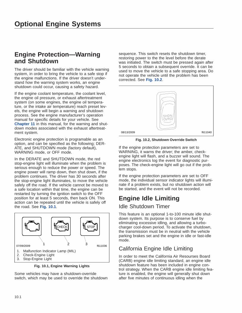
Engine Protection—Warningand ShutdownThe driver should be familiar with the vehicle warningsystem, in order to bring the vehicle to a safe stop ifthe engine malfunctions. If the driver doesn’t under-stand how the warning system works, an engineshutdown could occur, causing a safety hazard.
If the engine coolant temperature, the coolant level,the engine oil pressure, or exhaust aftertreatmentsystem (on some engines, the engine oil tempera-ture, or the intake air temperature) reach preset lev-els, the engine will begin a warning and shutdownprocess. See the engine manufacturer’s operationmanual for specific details for your vehicle. SeeChapter 11 in this manual, for the warning and shut-down modes associated with the exhaust aftertreat-ment system.
Electronic engine protection is programable as anoption, and can be specified as the following; DER-ATE, and SHUTDOWN mode (factory default),WARNING mode, or OFF mode.
In the DERATE and SHUTDOWN mode, the redstop-engine light will illuminate when the problem isserious enough to reduce the power or speed. Theengine power will ramp down, then shut down, if theproblem continues. The driver has 30 seconds afterthe stop-engine light illuminates, to move the vehiclesafely off the road. If the vehicle cannot be moved toa safe location within that time, the engine can berestarted by turning the ignition switch to the OFFposition for at least 5 seconds, then back ON. Thisaction can be repeated until the vehicle is safely offthe road. See Fig. 10.1 .
Some vehicles may have a shutdown-overrideswitch, which may be used to override the shutdown
sequence. This switch resets the shutdown timer,restoring power to the the level before the deratewas initiated. The switch must be pressed again after5 seconds to obtain a subsequent override. It can beused to move the vehicle to a safe stopping area. Donot operate the vehicle until the problem has beencorrected. See Fig. 10.2 .
If the engine protection parameters are set toWARNING, it warns the driver; the amber, check-engine light will flash, and a buzzer will sound. Theengine electronics log the event for diagnostic pur-poses. The check-engine light will go out if the prob-lem stops.
If the engine protection parameters are set to OFFmode, the individual sensor indicator lights will illumi-nate if a problem exists, but no shutdown action willbe started, and the event will not be recorded.
Engine Idle LimitingIdle Shutdown TimerThis feature is an optional 1-to-100 minute idle shut-down system. Its purpose is to conserve fuel byeliminating excessive idling, and allowing a turbo-charger cool-down period. To activate the shutdown,the transmission must be in neutral with the vehicleparking brakes set and the engine in idle or fast-idlemode.
California Engine Idle LimitingIn order to meet the California Air Resourses Board(CARB) engine idle limiting standard, an engine idleshutdown feature has been included in engine con-trol strategy. When the CARB engine idle limiting fea-ture is enabled, the engine will generally shut downafter five minutes of continuous idling when the
07/09/2009 f6110361 2 3
CHECK STOP
1. Malfunction Indicator Lamp (MIL)2. Check-Engine Light3. Stop-Engine Light
Fig. 10.1, Engine Warning Lights
08/13/2009 f611040
Fig. 10.2, Shutdown Override Switch
Optional Engine Systems
10.1
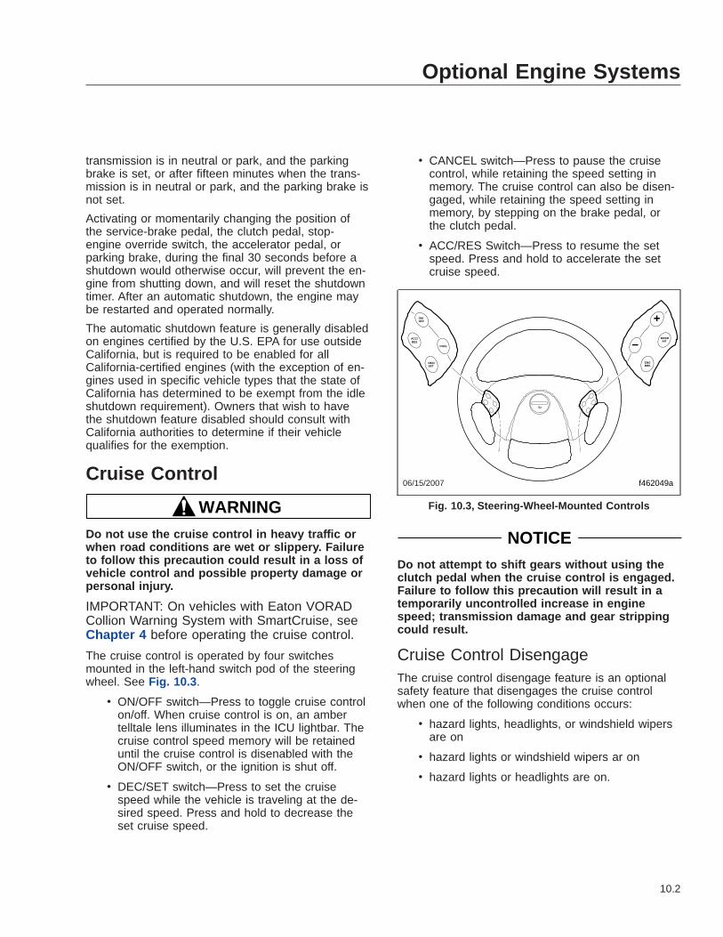
transmission is in neutral or park, and the parkingbrake is set, or after fifteen minutes when the trans-mission is in neutral or park, and the parking brake isnot set.
Activating or momentarily changing the position ofthe service-brake pedal, the clutch pedal, stop-engine override switch, the accelerator pedal, orparking brake, during the final 30 seconds before ashutdown would otherwise occur, will prevent the en-gine from shutting down, and will reset the shutdowntimer. After an automatic shutdown, the engine maybe restarted and operated normally.
The automatic shutdown feature is generally disabledon engines certified by the U.S. EPA for use outsideCalifornia, but is required to be enabled for allCalifornia-certified engines (with the exception of en-gines used in specific vehicle types that the state ofCalifornia has determined to be exempt from the idleshutdown requirement). Owners that wish to havethe shutdown feature disabled should consult withCalifornia authorities to determine if their vehiclequalifies for the exemption.
Cruise Control
WARNINGDo not use the cruise control in heavy traffic orwhen road conditions are wet or slippery. Failureto follow this precaution could result in a loss ofvehicle control and possible property damage orpersonal injury.
IMPORTANT: On vehicles with Eaton VORADCollion Warning System with SmartCruise, seeChapter 4 before operating the cruise control.
The cruise control is operated by four switchesmounted in the left-hand switch pod of the steeringwheel. See Fig. 10.3 .
• ON/OFF switch—Press to toggle cruise controlon/off. When cruise control is on, an ambertelltale lens illuminates in the ICU lightbar. Thecruise control speed memory will be retaineduntil the cruise control is disenabled with theON/OFF switch, or the ignition is shut off.
• DEC/SET switch—Press to set the cruisespeed while the vehicle is traveling at the de-sired speed. Press and hold to decrease theset cruise speed.
• CANCEL switch—Press to pause the cruisecontrol, while retaining the speed setting inmemory. The cruise control can also be disen-gaged, while retaining the speed setting inmemory, by stepping on the brake pedal, orthe clutch pedal.
• ACC/RES Switch—Press to resume the setspeed. Press and hold to accelerate the setcruise speed.
NOTICEDo not attempt to shift gears without using theclutch pedal when the cruise control is engaged.Failure to follow this precaution will result in atemporarily uncontrolled increase in enginespeed; transmission damage and gear strippingcould result.
Cruise Control DisengageThe cruise control disengage feature is an optionalsafety feature that disengages the cruise controlwhen one of the following conditions occurs:
• hazard lights, headlights, or windshield wipersare on
• hazard lights or windshield wipers ar on
• hazard lights or headlights are on.
06/15/2007
ON/OFF
ACC/RES
CNCL
DEC/SET
MRKRINT
ENGBRK
−
+
f462049a
Fig. 10.3, Steering-Wheel-Mounted Controls
Optional Engine Systems
10.2
Predictive Cruise ControlRun Smart Predictive Cruise Control™ is an optionalfuel savings application that adjusts the vehiclespeed predictively, based on the approaching roadprofile. Using 3D digital map technology and GPS,Predictive Cruise Control evaluates the upcomingroad grade about a mile in advance to determine themost fuel efficient vehicle speed. Vehicles equippedwith Predictive Cruise Control have a sticker on thedash indicating that the system is installed in the ve-hicle. See Fig. 10.4 .
Predictive Cruise Control will vary the vehicle setcruise speed by up to 6% depending on the ap-proaching road grade. If the engine brake is enabled,Predictive Cruise will automatically engage the en-gine brakes when the actual vehicle speed exceedsthe cruise set speed by 6%.
When Predictive Cruise Control is active, the drivermay experience variability in the set speed of thevehicle. This is different from conventional cruisecontrol, which maintains the speed set by the driver.
WARNINGApply brakes and downshift as necessary whendriving on downhill grades. Predictive CruiseControl does not adequately control vehiclespeed on steep downhill grades. Failure to usenormal braking techniques when PredictiveCruise Control is active could result in personalinjury and vehicle damage.
The 3D digital map database contains road profileinformation for over 200,000 highway miles (322,000km) in the 48 contiguous United States, including allInterstate and many major highways.
IMPORTANT: Predictive Cruise Control adjuststhe vehicle set speed to achieve maximum fuel
economy, but it does not account for traffic flowsor surrounding vehicles. Predictive Cruise Con-trol is compatible with SmartCruise, but it doesnot perform the same function. SmartCruisemaintains the vehicle’s headway distance byde-fueling and applying the engine brake.
If there is a problem with the normal operationof Predictive Cruise Control, the system revertsto conventional cruise control.
Driver interaction with Predictive Cruise Control is thesame as conventional cruise control, using existingcruise control switches. In the event of a problemwith Predictive Cruise Control, or when driving on aroad with no profile information available in the 3Ddigital map database, the system reverts to conven-tional cruise control.
Power Takeoff (PTO) GovernorFront Engine Power Take Offs (PTO) are devicesused to tap into engine power to run auxiliary de-vices. Common uses are vehicles with hydraulicpumps which power additional equipment. The fol-lowing instructions are general guidelines for operat-ing a PTO.
1. Set the parking brake. Shift the transmission toneutral.
2. Press the dash PTO switch. Release the switchwhen the light begins to blink.
When the light comes on steadily, the PTO isengaged and ready to operate. In stationarymode, the vehicle must remain in neutral with theparking brake set.
3. To activate the mobile mode, shift from neutral toreverse, 1st, or 2nd gear. The clutch will openand the PTO will disengage for a moment.
4. Touch the throttle pedal to close the clutch andengage the PTO in mobile mode. The PTO maybe operated with the transmission in the follow-ing gears only: R-N-1-2.
NOTE: Do not attempt to change gears whilethe vehicle is moving. The transmission will ig-nore the request.
5. To end the mobile mode, bring the vehicle to astop. The clutch will open and shut off power tothe PTO.
04/15/2009 f100149
Fig. 10.4, Run Smart Predictive Cruise Control Sticker
Optional Engine Systems
10.3
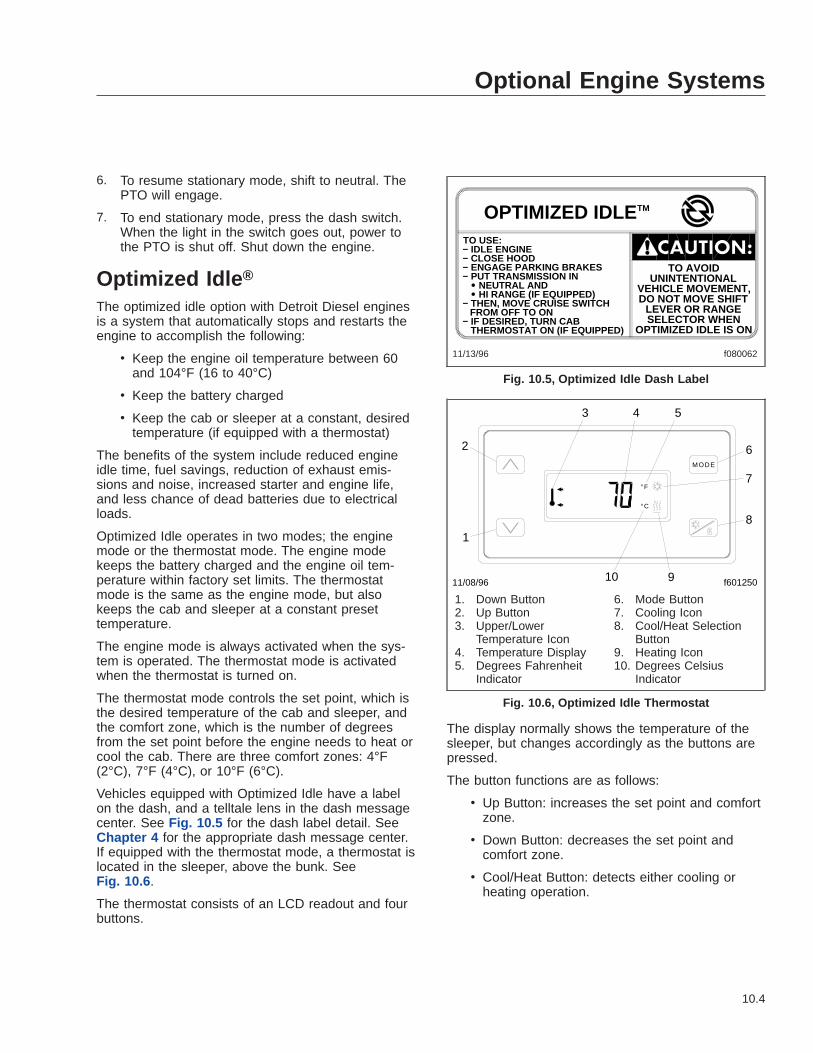
6. To resume stationary mode, shift to neutral. ThePTO will engage.
7. To end stationary mode, press the dash switch.When the light in the switch goes out, power tothe PTO is shut off. Shut down the engine.
Optimized Idle ®
The optimized idle option with Detroit Diesel enginesis a system that automatically stops and restarts theengine to accomplish the following:
• Keep the engine oil temperature between 60and 104°F (16 to 40°C)
• Keep the battery charged
• Keep the cab or sleeper at a constant, desiredtemperature (if equipped with a thermostat)
The benefits of the system include reduced engineidle time, fuel savings, reduction of exhaust emis-sions and noise, increased starter and engine life,and less chance of dead batteries due to electricalloads.
Optimized Idle operates in two modes; the enginemode or the thermostat mode. The engine modekeeps the battery charged and the engine oil tem-perature within factory set limits. The thermostatmode is the same as the engine mode, but alsokeeps the cab and sleeper at a constant presettemperature.
The engine mode is always activated when the sys-tem is operated. The thermostat mode is activatedwhen the thermostat is turned on.
The thermostat mode controls the set point, which isthe desired temperature of the cab and sleeper, andthe comfort zone, which is the number of degreesfrom the set point before the engine needs to heat orcool the cab. There are three comfort zones: 4°F(2°C), 7°F (4°C), or 10°F (6°C).
Vehicles equipped with Optimized Idle have a labelon the dash, and a telltale lens in the dash messagecenter. See Fig. 10.5 for the dash label detail. SeeChapter 4 for the appropriate dash message center.If equipped with the thermostat mode, a thermostat islocated in the sleeper, above the bunk. SeeFig. 10.6 .
The thermostat consists of an LCD readout and fourbuttons.
The display normally shows the temperature of thesleeper, but changes accordingly as the buttons arepressed.
The button functions are as follows:
• Up Button: increases the set point and comfortzone.
• Down Button: decreases the set point andcomfort zone.
• Cool/Heat Button: detects either cooling orheating operation.
11/13/96 f080062
TO AVOIDUNINTENTIONAL
VEHICLE MOVEMENT,DO NOT MOVE SHIFT
LEVER OR RANGESELECTOR WHEN
OPTIMIZED IDLE IS ON
OPTIMIZED IDLETM
TO USE:− IDLE ENGINE− CLOSE HOOD− ENGAGE PARKING BRAKES− PUT TRANSMISSION IN
NEUTRAL ANDHI RANGE (IF EQUIPPED)
− THEN, MOVE CRUISE SWITCHFROM OFF TO ON
− IF DESIRED, TURN CABTHERMOSTAT ON (IF EQUIPPED)
Fig. 10.5, Optimized Idle Dash Label
MODE
°F
°C
11/08/96
1
2
3 4 5
6
7
8
910 f601250
1. Down Button2. Up Button3. Upper/Lower
Temperature Icon4. Temperature Display5. Degrees Fahrenheit
Indicator
6. Mode Button7. Cooling Icon8. Cool/Heat Selection
Button9. Heating Icon10. Degrees Celsius
Indicator
Fig. 10.6, Optimized Idle Thermostat
Optional Engine Systems
10.4
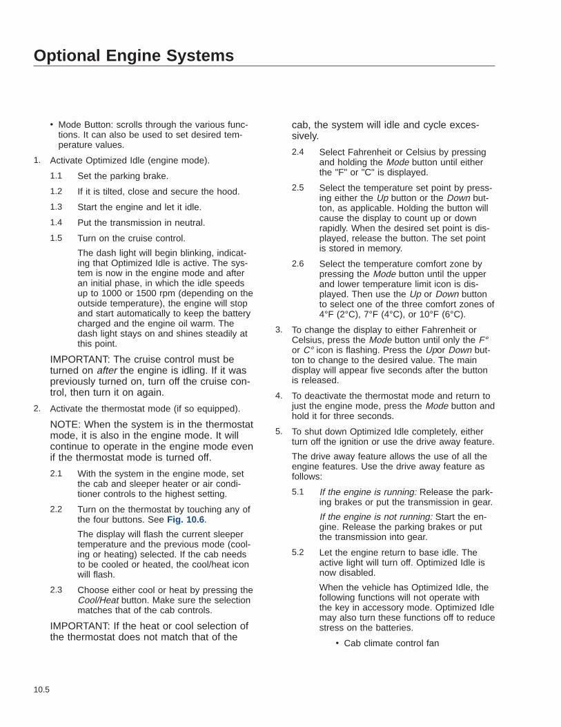
• Mode Button: scrolls through the various func-tions. It can also be used to set desired tem-perature values.
1. Activate Optimized Idle (engine mode).
1.1 Set the parking brake.
1.2 If it is tilted, close and secure the hood.
1.3 Start the engine and let it idle.
1.4 Put the transmission in neutral.
1.5 Turn on the cruise control.
The dash light will begin blinking, indicat-ing that Optimized Idle is active. The sys-tem is now in the engine mode and afteran initial phase, in which the idle speedsup to 1000 or 1500 rpm (depending on theoutside temperature), the engine will stopand start automatically to keep the batterycharged and the engine oil warm. Thedash light stays on and shines steadily atthis point.
IMPORTANT: The cruise control must beturned on after the engine is idling. If it waspreviously turned on, turn off the cruise con-trol, then turn it on again.
2. Activate the thermostat mode (if so equipped).
NOTE: When the system is in the thermostatmode, it is also in the engine mode. It willcontinue to operate in the engine mode evenif the thermostat mode is turned off.
2.1 With the system in the engine mode, setthe cab and sleeper heater or air condi-tioner controls to the highest setting.
2.2 Turn on the thermostat by touching any ofthe four buttons. See Fig. 10.6 .
The display will flash the current sleepertemperature and the previous mode (cool-ing or heating) selected. If the cab needsto be cooled or heated, the cool/heat iconwill flash.
2.3 Choose either cool or heat by pressing theCool/Heat button. Make sure the selectionmatches that of the cab controls.
IMPORTANT: If the heat or cool selection ofthe thermostat does not match that of the
cab, the system will idle and cycle exces-sively.
2.4 Select Fahrenheit or Celsius by pressingand holding the Mode button until eitherthe "F" or "C" is displayed.
2.5 Select the temperature set point by press-ing either the Up button or the Down but-ton, as applicable. Holding the button willcause the display to count up or downrapidly. When the desired set point is dis-played, release the button. The set pointis stored in memory.
2.6 Select the temperature comfort zone bypressing the Mode button until the upperand lower temperature limit icon is dis-played. Then use the Up or Down buttonto select one of the three comfort zones of4°F (2°C), 7°F (4°C), or 10°F (6°C).
3. To change the display to either Fahrenheit orCelsius, press the Mode button until only the F°or C° icon is flashing. Press the Upor Down but-ton to change to the desired value. The maindisplay will appear five seconds after the buttonis released.
4. To deactivate the thermostat mode and return tojust the engine mode, press the Mode button andhold it for three seconds.
5. To shut down Optimized Idle completely, eitherturn off the ignition or use the drive away feature.
The drive away feature allows the use of all theengine features. Use the drive away feature asfollows:
5.1 If the engine is running: Release the park-ing brakes or put the transmission in gear.
If the engine is not running: Start the en-gine. Release the parking brakes or putthe transmission into gear.
5.2 Let the engine return to base idle. Theactive light will turn off. Optimized Idle isnow disabled.
When the vehicle has Optimized Idle, thefollowing functions will not operate withthe key in accessory mode. Optimized Idlemay also turn these functions off to reducestress on the batteries.
• Cab climate control fan
Optional Engine Systems
10.5
• Sleeper climate control fan
• Mirror heating (driver and passen-ger)
• Fuel/water separator heating ele-ment
• Seat heating
• Advertising light
• Auxiliary circulation fan (windshield)
• Air dryer
Optional Engine Systems
10.6
11
Aftertreatment Systems(ATS)
Exhaust Aftertreatment Systems . . . . . . . . . . . . . . . . . . . . . . . . . . . . . . . . . . . . . . . . . . . . . . . . . . . . 11.1Diesel Exhaust Fluid and Tank (EPA10) . . . . . . . . . . . . . . . . . . . . . . . . . . . . . . . . . . . . . . . . . . . . . . 11.6
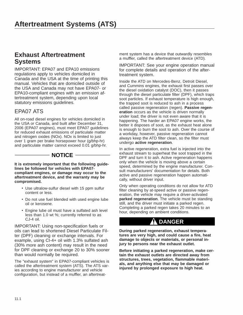
Exhaust AftertreatmentSystemsIMPORTANT: EPA07 and EPA10 emissionsregulations apply to vehicles domiciled inCanada and the USA at the time of printing thismanual. Vehicles that are domiciled outside ofthe USA and Canada may not have EPA07- orEPA10-compliant engines with an emission af-tertreatment system, depending upon localstatutory emissions guidelines.
EPA07 ATSAll on-road diesel engines for vehicles domiciled inthe USA or Canada, and built after December 31,2006 (EPA07 engines), must meet EPA07 guidelinesfor reduced exhaust emissions of particulate matterand nitrogen oxides (NOx). NOx is limited to justover 1 gram per brake horsepower hour (g/bhp-hr)and particulate matter cannot exceed 0.01 g/bhp-hr.
NOTICEIt is extremely important that the following guide-lines be followed for vehicles with EPA07-compliant engines, or damage may occur to theaftertreatment device, and the warranty may becompromised.
• Use ultralow-sulfur diesel with 15 ppm sulfurcontent or less.
• Do not use fuel blended with used engine lubeoil or kerosene.
• Engine lube oil must have a sulfated ash levelless than 1.0 wt %; currently referred to asCJ-4 oil.
IMPORTANT: Using non-specification fuels oroils can lead to shortened Diesel Particulate Fil-ter (DPF) cleaning or exchange intervals. Forexample, using CI-4+ oil with 1.3% sulfated ash(30% more ash content) may result in the needfor DPF cleaning or exchange 20 to 30% soonerthan would normally be required.
The "exhaust system" in EPA07-compliant vehicles iscalled the aftertreatment system (ATS). The ATS var-ies according to engine manufacturer and vehicleconfiguration, but instead of a muffler, an aftertreat-
ment system has a device that outwardly resemblesa muffler, called the aftertreatment device (ATD).
IMPORTANT: See your engine operation manualfor complete details and operation of the after-treatment system.
Inside the ATD on Mercedes-Benz, Detroit Diesel,and Cummins engines, the exhaust first passes overthe diesel oxidation catalyst (DOC), then it passesthrough the diesel particulate filter (DPF), which trapssoot particles. If exhaust temperature is high enough,the trapped soot is reduced to ash in a processcalled passive regeneration (regen). Passive regen-eration occurs as the vehicle is driven normallyunder load; the driver is not even aware that it ishappening. The harder an EPA07 engine works, thebetter it disposes of soot, as the exhaust heat aloneis enough to burn the soot to ash. Over the course ofa workday, however, passive regeneration cannotalways keep the ATD filter clean, so the filter mustundergo active regeneration .
In active regeneration, extra fuel is injected into theexhaust stream to superheat the soot trapped in theDPF and turn it to ash. Active regeneration happensonly when the vehicle is moving above a certainspeed, determined by the engine manufacturer. Con-sult manufacturers’ documentation for details. Bothactive and passive regeneration happen automati-cally, without driver input.
Only when operating conditions do not allow for ATDfilter cleaning by at-speed active or passive regen-eration, the vehicle may require a driver-activatedparked regeneration . The vehicle must be standingstill, and the driver must initiate a parked regen.Completing a parked regen takes 20 minutes to anhour, depending on ambient conditions.
DANGERDuring parked regeneration, exhaust tempera-tures are very high, and could cause a fire, heatdamage to objects or materials, or personal in-jury to persons near the exhaust outlet.
Before initiating a parked regeneration, make cer-tain the exhaust outlets are directed away fromstructures, trees, vegetation, flammable materi-als, and anything else that may be damaged orinjured by prolonged exposure to high heat.
Aftertreatment Systems (ATS)
11.1
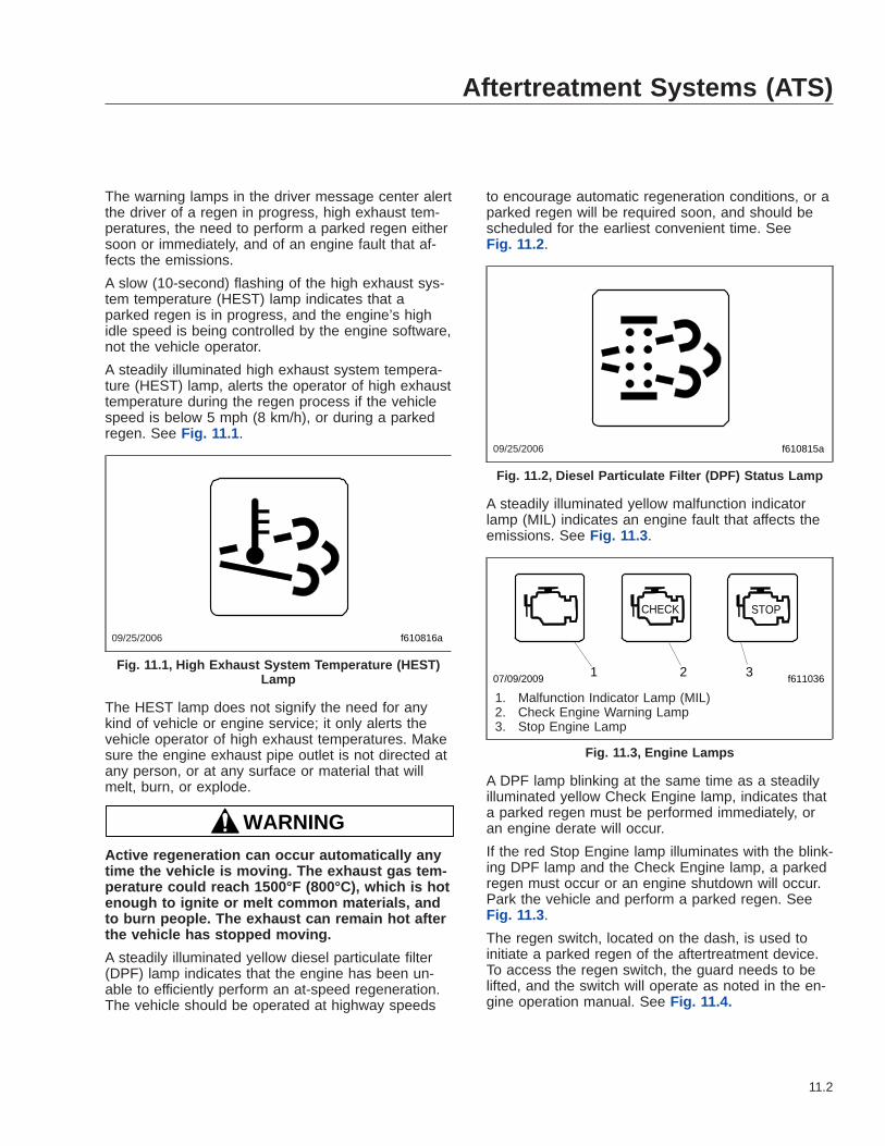
The warning lamps in the driver message center alertthe driver of a regen in progress, high exhaust tem-peratures, the need to perform a parked regen eithersoon or immediately, and of an engine fault that af-fects the emissions.
A slow (10-second) flashing of the high exhaust sys-tem temperature (HEST) lamp indicates that aparked regen is in progress, and the engine’s highidle speed is being controlled by the engine software,not the vehicle operator.
A steadily illuminated high exhaust system tempera-ture (HEST) lamp, alerts the operator of high exhausttemperature during the regen process if the vehiclespeed is below 5 mph (8 km/h), or during a parkedregen. See Fig. 11.1 .
The HEST lamp does not signify the need for anykind of vehicle or engine service; it only alerts thevehicle operator of high exhaust temperatures. Makesure the engine exhaust pipe outlet is not directed atany person, or at any surface or material that willmelt, burn, or explode.
WARNINGActive regeneration can occur automatically anytime the vehicle is moving. The exhaust gas tem-perature could reach 1500°F (800°C), which is hotenough to ignite or melt common materials, andto burn people. The exhaust can remain hot afterthe vehicle has stopped moving.
A steadily illuminated yellow diesel particulate filter(DPF) lamp indicates that the engine has been un-able to efficiently perform an at-speed regeneration.The vehicle should be operated at highway speeds
to encourage automatic regeneration conditions, or aparked regen will be required soon, and should bescheduled for the earliest convenient time. SeeFig. 11.2 .
A steadily illuminated yellow malfunction indicatorlamp (MIL) indicates an engine fault that affects theemissions. See Fig. 11.3 .
A DPF lamp blinking at the same time as a steadilyilluminated yellow Check Engine lamp, indicates thata parked regen must be performed immediately, oran engine derate will occur.
If the red Stop Engine lamp illuminates with the blink-ing DPF lamp and the Check Engine lamp, a parkedregen must occur or an engine shutdown will occur.Park the vehicle and perform a parked regen. SeeFig. 11.3 .
The regen switch, located on the dash, is used toinitiate a parked regen of the aftertreatment device.To access the regen switch, the guard needs to belifted, and the switch will operate as noted in the en-gine operation manual. See Fig. 11.4.
09/25/2006 f610816a
Fig. 11.1, High Exhaust System Temperature (HEST)Lamp
09/25/2006 f610815a
Fig. 11.2, Diesel Particulate Filter (DPF) Status Lamp
07/09/2009 f6110361 2 3
CHECK STOP
1. Malfunction Indicator Lamp (MIL)2. Check Engine Warning Lamp3. Stop Engine Lamp
Fig. 11.3, Engine Lamps
Aftertreatment Systems (ATS)
11.2
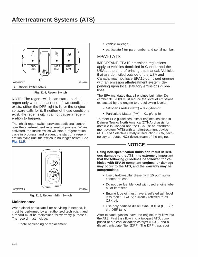
NOTE: The regen switch can start a parkedregen only when at least one of two conditionsexists: either the DPF light is lit, or the enginesoftware calls for it. If neither of those conditionsexist, the regen switch cannot cause a regen-eration to happen.
The inhibit regen switch provides additional controlover the aftertreatment regeneration process. Whenactivated, the inhibit switch will stop a regenerationcycle in progress, and prevent the start of a regen-eration cycle until the switch is no longer active. SeeFig. 11.5.
MaintenanceWhen diesel particulate filter servicing is needed, itmust be performed by an authorized technician, anda record must be maintained for warranty purposes.The record must include:
• date of cleaning or replacement;
• vehicle mileage;
• particulate filter part number and serial number.
EPA10 ATSIMPORTANT: EPA10 emissions regulationsapply to vehicles domiciled in Canada and theUSA at the time of printing this manual. Vehiclesthat are domiciled outside of the USA andCanada may not have EPA10-compliant engineswith an emission aftertreatment system, de-pending upon local statutory emissions guide-lines.
The EPA mandates that all engines built after De-cember 31, 2009 must reduce the level of emissionsexhausted by the engine to the following levels:
• Nitrogen Oxides (NOx) – 0.2 g/bhp-hr
• Particulate Matter (PM) – .01 g/bhp-hr
To meet EPA guidelines, diesel engines installed inDaimler Trucks North America (DTNA) chassis fordomicile in Canada and the USA use an aftertreat-ment system (ATS) with an aftertreatment device(ATD) and Selective Catalytic Reduction (SCR) tech-nology to reduce NOx downstream of the engine.
NOTICEUsing non-specification fluids can result in seri-ous damage to the ATS. It is extremely importantthat the following guidelines be followed for ve-hicles with EPA10-compliant engines, or damagemay occur to the ATD, and the warranty may becompromised.
• Use ultralow-sulfur diesel with 15 ppm sulfurcontent or less.
• Do not use fuel blended with used engine lubeoil or kerosene.
• Engine lube oil must have a sulfated ash levelless than 1.0 wt %; currently referred to asCJ-4 oil.
• Use only certified diesel exhaust fluid (DEF) inthe DEF tank.
After exhaust gasses leave the engine, they flow intothe ATS. First they flow into a two-part ATD, com-prised of a diesel oxidation catalyst (DOC), and adiesel particulate filter (DPF). The DPF traps soot
LAMPUTLY
HEATMIRR
BRKENG
HI
LO
05/04/2007 f6109181
1. Regen Switch Guard
Fig. 11.4, Regen Switch
f61094407/30/2009
Fig. 11.5, Regen Inhibit Switch
Aftertreatment Systems (ATS)
11.3
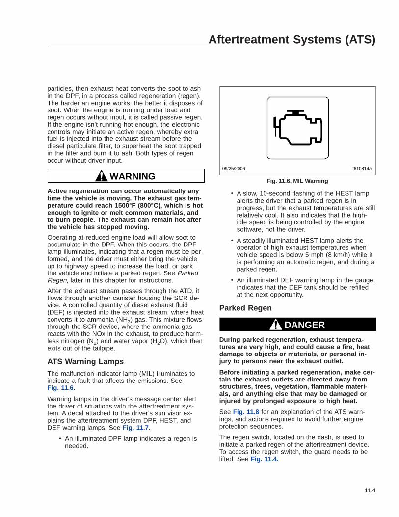
particles, then exhaust heat converts the soot to ashin the DPF, in a process called regeneration (regen).The harder an engine works, the better it disposes ofsoot. When the engine is running under load andregen occurs without input, it is called passive regen.If the engine isn’t running hot enough, the electroniccontrols may initiate an active regen, whereby extrafuel is injected into the exhaust stream before thediesel particulate filter, to superheat the soot trappedin the filter and burn it to ash. Both types of regenoccur without driver input.
WARNINGActive regeneration can occur automatically anytime the vehicle is moving. The exhaust gas tem-perature could reach 1500°F (800°C), which is hotenough to ignite or melt common materials, andto burn people. The exhaust can remain hot afterthe vehicle has stopped moving.
Operating at reduced engine load will allow soot toaccumulate in the DPF. When this occurs, the DPFlamp illuminates, indicating that a regen must be per-formed, and the driver must either bring the vehicleup to highway speed to increase the load, or parkthe vehicle and initiate a parked regen. See ParkedRegen, later in this chapter for instructions.
After the exhaust stream passes through the ATD, itflows through another canister housing the SCR de-vice. A controlled quantity of diesel exhaust fluid(DEF) is injected into the exhaust stream, where heatconverts it to ammonia (NH3) gas. This mixture flowsthrough the SCR device, where the ammonia gasreacts with the NOx in the exhaust, to produce harm-less nitrogen (N2) and water vapor (H2O), which thenexits out of the tailpipe.
ATS Warning LampsThe malfunction indicator lamp (MIL) illuminates toindicate a fault that affects the emissions. SeeFig. 11.6 .
Warning lamps in the driver’s message center alertthe driver of situations with the aftertreatment sys-tem. A decal attached to the driver’s sun visor ex-plains the aftertreatment system DPF, HEST, andDEF warning lamps. See Fig. 11.7 .
• An illuminated DPF lamp indicates a regen isneeded.
• A slow, 10-second flashing of the HEST lampalerts the driver that a parked regen is inprogress, but the exhaust temperatures are stillrelatively cool. It also indicates that the high-idle speed is being controlled by the enginesoftware, not the driver.
• A steadily illuminated HEST lamp alerts theoperator of high exhaust temperatures whenvehicle speed is below 5 mph (8 km/h) while itis performing an automatic regen, and during aparked regen.
• An illuminated DEF warning lamp in the gauge,indicates that the DEF tank should be refilledat the next opportunity.
Parked Regen
DANGERDuring parked regeneration, exhaust tempera-tures are very high, and could cause a fire, heatdamage to objects or materials, or personal in-jury to persons near the exhaust outlet.
Before initiating a parked regeneration, make cer-tain the exhaust outlets are directed away fromstructures, trees, vegetation, flammable materi-als, and anything else that may be damaged orinjured by prolonged exposure to high heat.
See Fig. 11.8 for an explanation of the ATS warn-ings, and actions required to avoid further engineprotection sequences.
The regen switch, located on the dash, is used toinitiate a parked regen of the aftertreatment device.To access the regen switch, the guard needs to belifted. See Fig. 11.4.
09/25/2006 f610814a
Fig. 11.6, MIL Warning
Aftertreatment Systems (ATS)
11.4
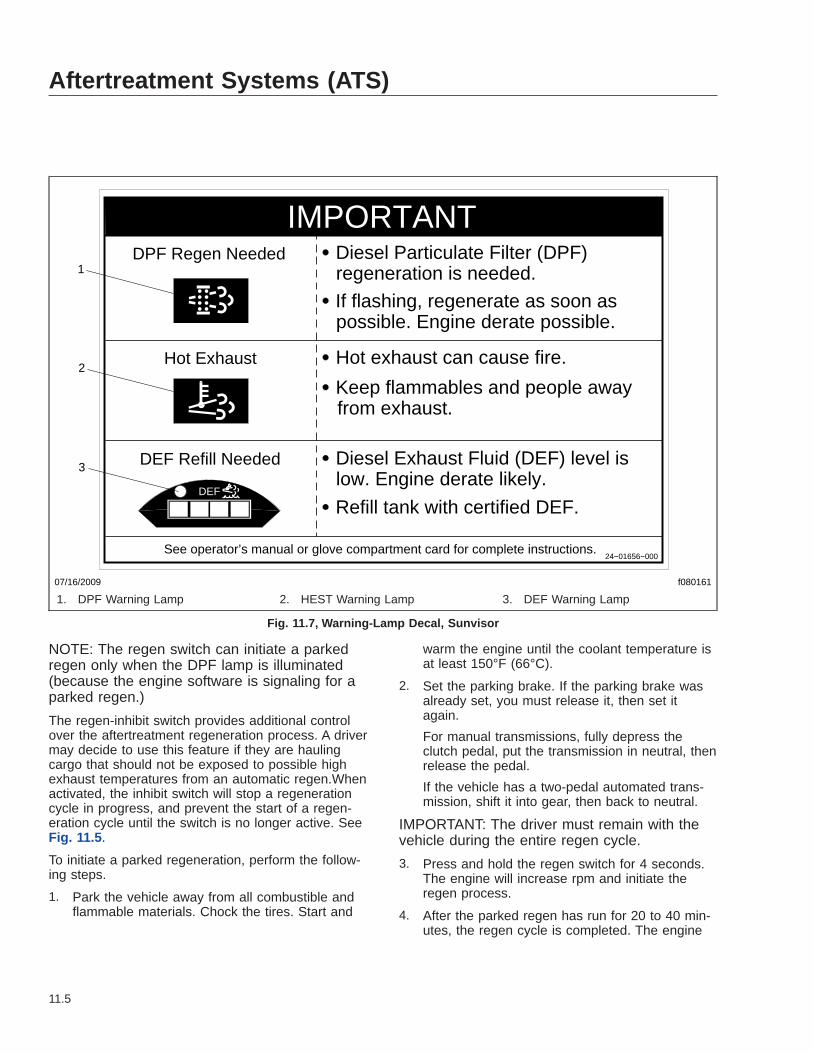
NOTE: The regen switch can initiate a parkedregen only when the DPF lamp is illuminated(because the engine software is signaling for aparked regen.)
The regen-inhibit switch provides additional controlover the aftertreatment regeneration process. A drivermay decide to use this feature if they are haulingcargo that should not be exposed to possible highexhaust temperatures from an automatic regen.Whenactivated, the inhibit switch will stop a regenerationcycle in progress, and prevent the start of a regen-eration cycle until the switch is no longer active. SeeFig. 11.5 .
To initiate a parked regeneration, perform the follow-ing steps.
1. Park the vehicle away from all combustible andflammable materials. Chock the tires. Start and
warm the engine until the coolant temperature isat least 150°F (66°C).
2. Set the parking brake. If the parking brake wasalready set, you must release it, then set itagain.
For manual transmissions, fully depress theclutch pedal, put the transmission in neutral, thenrelease the pedal.
If the vehicle has a two-pedal automated trans-mission, shift it into gear, then back to neutral.
IMPORTANT: The driver must remain with thevehicle during the entire regen cycle.
3. Press and hold the regen switch for 4 seconds.The engine will increase rpm and initiate theregen process.
4. After the parked regen has run for 20 to 40 min-utes, the regen cycle is completed. The engine
DPF Regen Needed
Hot Exhaust
DEF Refill Needed
Diesel Particulate Filter (DPF)regeneration is needed.
If flashing, regenerate as soon aspossible. Engine derate possible.
Hot exhaust can cause fire.
Keep flammables and people awayfrom exhaust.
Diesel Exhaust Fluid (DEF) level islow. Engine derate likely.
Refill tank with certified DEF.
See operator’s manual or glove compartment card for complete instructions.24−01656−000
IMPORTANT
DEF
07/16/2009 f080161
1
2
3
1. DPF Warning Lamp 2. HEST Warning Lamp 3. DEF Warning Lamp
Fig. 11.7, Warning-Lamp Decal, Sunvisor
Aftertreatment Systems (ATS)
11.5
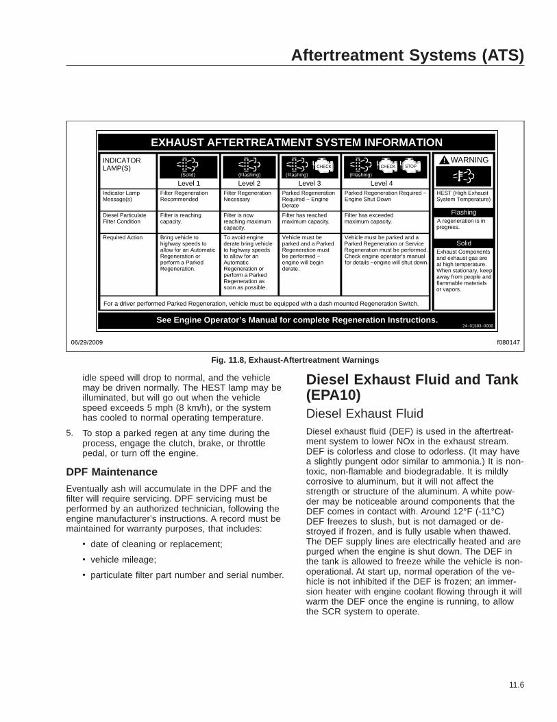
idle speed will drop to normal, and the vehiclemay be driven normally. The HEST lamp may beilluminated, but will go out when the vehiclespeed exceeds 5 mph (8 km/h), or the systemhas cooled to normal operating temperature.
5. To stop a parked regen at any time during theprocess, engage the clutch, brake, or throttlepedal, or turn off the engine.
DPF MaintenanceEventually ash will accumulate in the DPF and thefilter will require servicing. DPF servicing must beperformed by an authorized technician, following theengine manufacturer’s instructions. A record must bemaintained for warranty purposes, that includes:
• date of cleaning or replacement;
• vehicle mileage;
• particulate filter part number and serial number.
Diesel Exhaust Fluid and Tank(EPA10)Diesel Exhaust FluidDiesel exhaust fluid (DEF) is used in the aftertreat-ment system to lower NOx in the exhaust stream.DEF is colorless and close to odorless. (It may havea slightly pungent odor similar to ammonia.) It is non-toxic, non-flamable and biodegradable. It is mildlycorrosive to aluminum, but it will not affect thestrength or structure of the aluminum. A white pow-der may be noticeable around components that theDEF comes in contact with. Around 12°F (-11°C)DEF freezes to slush, but is not damaged or de-stroyed if frozen, and is fully usable when thawed.The DEF supply lines are electrically heated and arepurged when the engine is shut down. The DEF inthe tank is allowed to freeze while the vehicle is non-operational. At start up, normal operation of the ve-hicle is not inhibited if the DEF is frozen; an immer-sion heater with engine coolant flowing through it willwarm the DEF once the engine is running, to allowthe SCR system to operate.
f080147
EXHAUST AFTERTREATMENT SYSTEM INFORMATION
Switch.
Level 1 Level 3Level 2 Level 4Filter RegenerationRecommended
Filter is reaching
Bring vehicle tohighway speeds to
Filter RegenerationNecessary
Filter is nowreaching maximumcapacity.
To avoid enginederate bring vehicle
Parked RegenerationRequired − EngineDerate
Filter has reachedmaximum capacity.
Vehicle must beparked and a Parked
Parked Regeneration Required −Engine Shut Down
Filter has exceededmaximum capacity
Vehicle must be parked and aParked Regeneration or Service
(Solid) (Flashing) (Flashing)
CHECK CHECK
(Flashing)
INDICATORLAMP(S)
Indicator LampMessage(s)
Diesel ParticulateFilter Condition
Required Action
capacity. .
STOP
See Engine Operator’s Manual for complete Regeneration Instructions.
allow for an AutomaticRegeneration orperform a ParkedRegeneration.
to highway speedsto allow for anAutomaticRegeneration orperform a ParkedRegeneration assoon as possible.
Regeneration mustbe performed −engine will beginderate.
Regeneration must be performed.Check engine operator’s manualfor details −engine will shut down.
For a driver performed Parked Regeneration, vehicle must be equipped with a dash mounted Regeneration Switch.
06/29/2009
24−01583−000B
WARNING
HEST (High ExhaustSystem Temperature)
Exhaust Componentsand exhaust gas areat high temperature. When stationary, keepaway from people andflammable materialsor vapors.
A regeneration is inprogress.
Flashing
Solid
Fig. 11.8, Exhaust-Aftertreatment Warnings
Aftertreatment Systems (ATS)
11.6
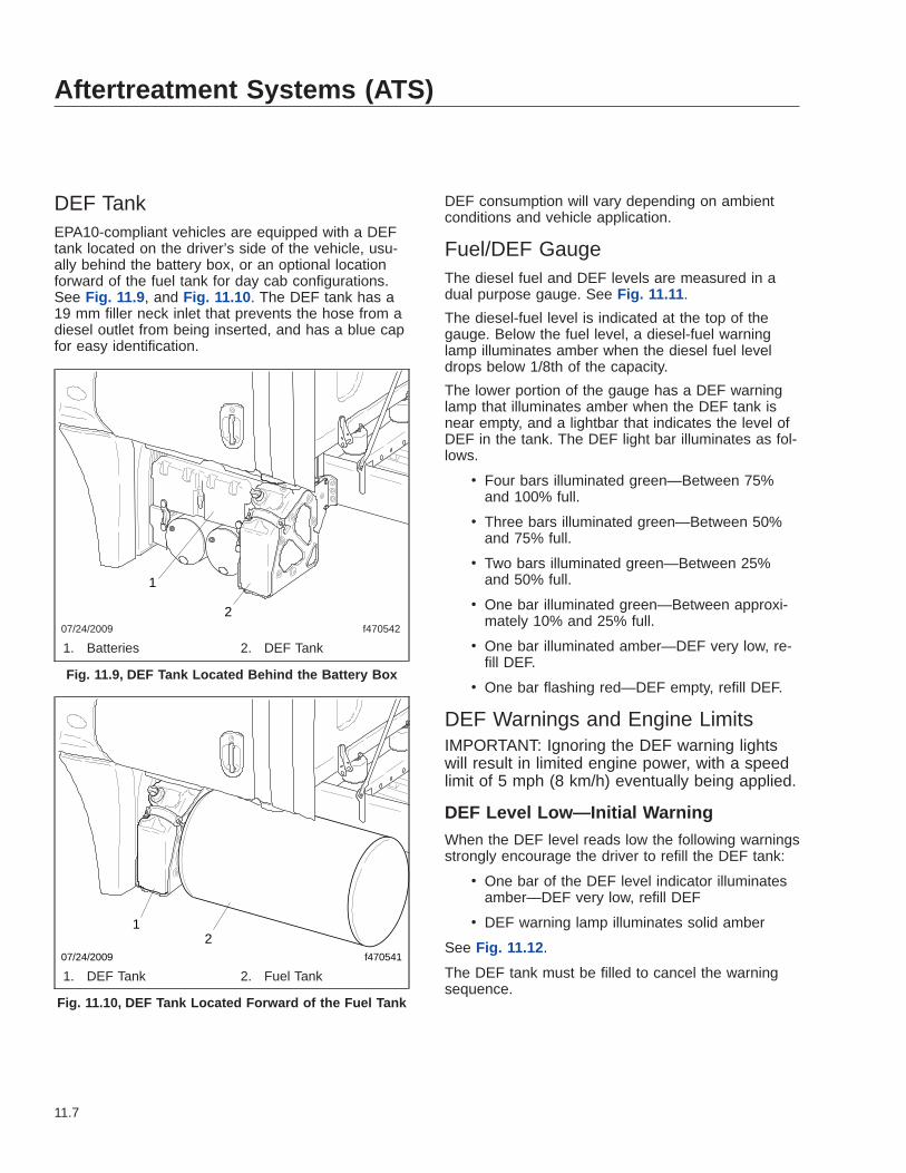
DEF TankEPA10-compliant vehicles are equipped with a DEFtank located on the driver’s side of the vehicle, usu-ally behind the battery box, or an optional locationforward of the fuel tank for day cab configurations.See Fig. 11.9 , and Fig. 11.10 . The DEF tank has a19 mm filler neck inlet that prevents the hose from adiesel outlet from being inserted, and has a blue capfor easy identification.
DEF consumption will vary depending on ambientconditions and vehicle application.
Fuel/DEF GaugeThe diesel fuel and DEF levels are measured in adual purpose gauge. See Fig. 11.11 .
The diesel-fuel level is indicated at the top of thegauge. Below the fuel level, a diesel-fuel warninglamp illuminates amber when the diesel fuel leveldrops below 1/8th of the capacity.
The lower portion of the gauge has a DEF warninglamp that illuminates amber when the DEF tank isnear empty, and a lightbar that indicates the level ofDEF in the tank. The DEF light bar illuminates as fol-lows.
• Four bars illuminated green—Between 75%and 100% full.
• Three bars illuminated green—Between 50%and 75% full.
• Two bars illuminated green—Between 25%and 50% full.
• One bar illuminated green—Between approxi-mately 10% and 25% full.
• One bar illuminated amber—DEF very low, re-fill DEF.
• One bar flashing red—DEF empty, refill DEF.
DEF Warnings and Engine LimitsIMPORTANT: Ignoring the DEF warning lightswill result in limited engine power, with a speedlimit of 5 mph (8 km/h) eventually being applied.
DEF Level Low—Initial WarningWhen the DEF level reads low the following warningsstrongly encourage the driver to refill the DEF tank:
• One bar of the DEF level indicator illuminatesamber—DEF very low, refill DEF
• DEF warning lamp illuminates solid amber
See Fig. 11.12 .
The DEF tank must be filled to cancel the warningsequence.
07/24/2009 f470542
1
2
1. Batteries 2. DEF Tank
Fig. 11.9, DEF Tank Located Behind the Battery Box
07/24/2009 f470541
12
1. DEF Tank 2. Fuel Tank
Fig. 11.10, DEF Tank Located Forward of the Fuel Tank
Aftertreatment Systems (ATS)
11.7
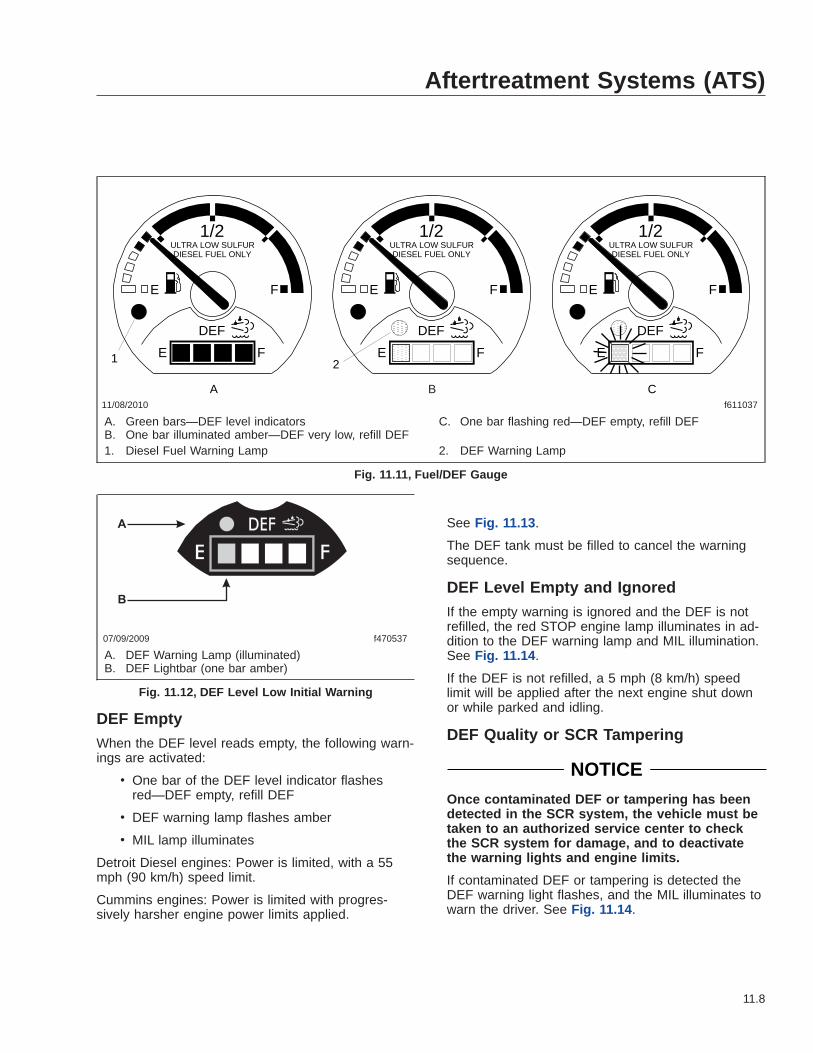
DEF EmptyWhen the DEF level reads empty, the following warn-ings are activated:
• One bar of the DEF level indicator flashesred—DEF empty, refill DEF
• DEF warning lamp flashes amber
• MIL lamp illuminates
Detroit Diesel engines: Power is limited, with a 55mph (90 km/h) speed limit.
Cummins engines: Power is limited with progres-sively harsher engine power limits applied.
See Fig. 11.13 .
The DEF tank must be filled to cancel the warningsequence.
DEF Level Empty and IgnoredIf the empty warning is ignored and the DEF is notrefilled, the red STOP engine lamp illuminates in ad-dition to the DEF warning lamp and MIL illumination.See Fig. 11.14 .
If the DEF is not refilled, a 5 mph (8 km/h) speedlimit will be applied after the next engine shut downor while parked and idling.
DEF Quality or SCR Tampering
NOTICEOnce contaminated DEF or tampering has beendetected in the SCR system, the vehicle must betaken to an authorized service center to checkthe SCR system for damage, and to deactivatethe warning lights and engine limits.
If contaminated DEF or tampering is detected theDEF warning light flashes, and the MIL illuminates towarn the driver. See Fig. 11.14 .
11/08/2010 f611037
B
1/2ULTRA LOW SULFURDIESEL FUEL ONLY
E F
DEF
FE
1/2ULTRA LOW SULFURDIESEL FUEL ONLY
E F
DEF
FE
1/2ULTRA LOW SULFURDIESEL FUEL ONLY
E F
DEF
FE
A C
1 2
A. Green bars—DEF level indicatorsB. One bar illuminated amber—DEF very low, refill DEF
C. One bar flashing red—DEF empty, refill DEF
1. Diesel Fuel Warning Lamp 2. DEF Warning Lamp
Fig. 11.11, Fuel/DEF Gauge
A
B
07/09/2009 f470537
A. DEF Warning Lamp (illuminated)B. DEF Lightbar (one bar amber)
Fig. 11.12, DEF Level Low Initial Warning
Aftertreatment Systems (ATS)
11.8
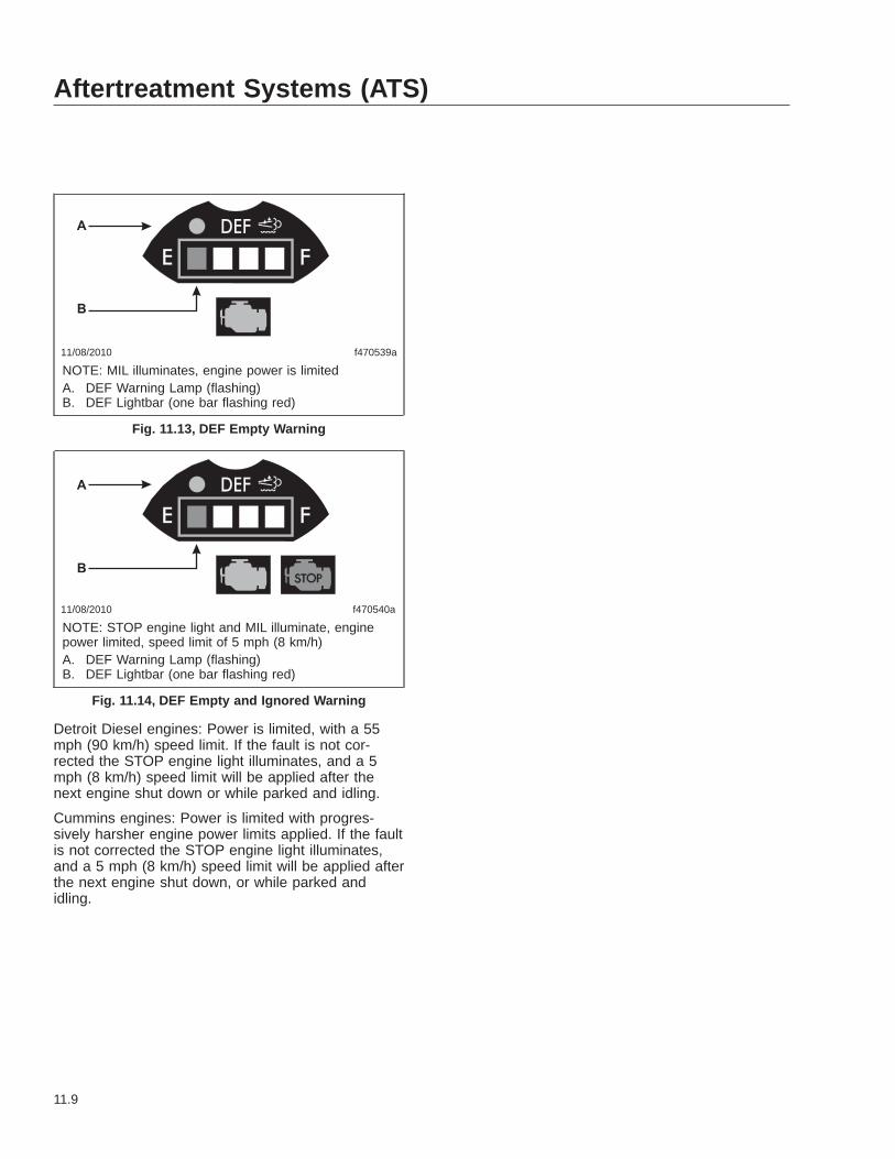
Detroit Diesel engines: Power is limited, with a 55mph (90 km/h) speed limit. If the fault is not cor-rected the STOP engine light illuminates, and a 5mph (8 km/h) speed limit will be applied after thenext engine shut down or while parked and idling.
Cummins engines: Power is limited with progres-sively harsher engine power limits applied. If the faultis not corrected the STOP engine light illuminates,and a 5 mph (8 km/h) speed limit will be applied afterthe next engine shut down, or while parked andidling.
A
B
11/08/2010 f470539a
NOTE: MIL illuminates, engine power is limitedA. DEF Warning Lamp (flashing)B. DEF Lightbar (one bar flashing red)
Fig. 11.13, DEF Empty Warning
A
B
11/08/2010 f470540a
NOTE: STOP engine light and MIL illuminate, enginepower limited, speed limit of 5 mph (8 km/h)A. DEF Warning Lamp (flashing)B. DEF Lightbar (one bar flashing red)
Fig. 11.14, DEF Empty and Ignored Warning
Aftertreatment Systems (ATS)
11.9
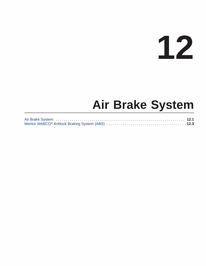
12
Air Brake SystemAir Brake System . . . . . . . . . . . . . . . . . . . . . . . . . . . . . . . . . . . . . . . . . . . . . . . . . . . . . . . . . . . . . . . . 12.1Meritor WABCO® Antilock Braking System (ABS) . . . . . . . . . . . . . . . . . . . . . . . . . . . . . . . . . . . . . . . 12.3
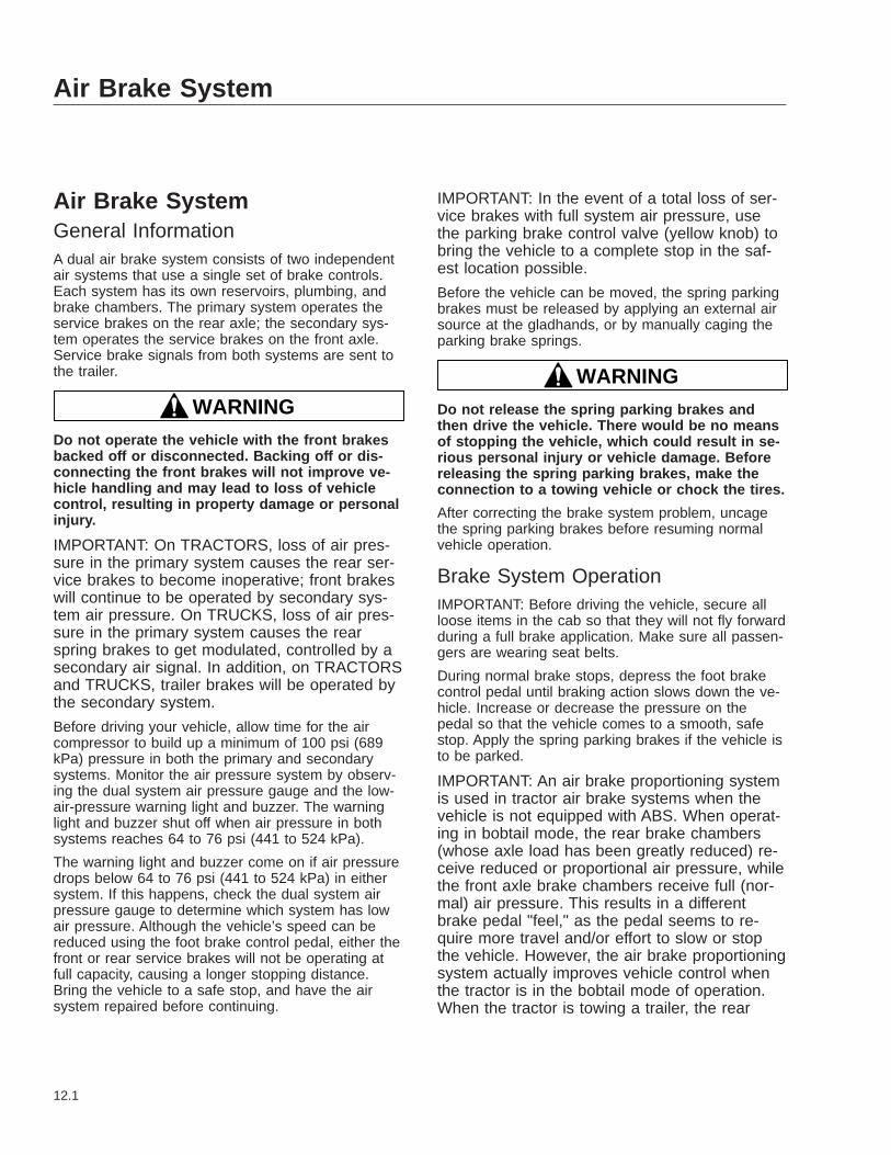
Air Brake SystemGeneral InformationA dual air brake system consists of two independentair systems that use a single set of brake controls.Each system has its own reservoirs, plumbing, andbrake chambers. The primary system operates theservice brakes on the rear axle; the secondary sys-tem operates the service brakes on the front axle.Service brake signals from both systems are sent tothe trailer.
WARNINGDo not operate the vehicle with the front brakesbacked off or disconnected. Backing off or dis-connecting the front brakes will not improve ve-hicle handling and may lead to loss of vehiclecontrol, resulting in property damage or personalinjury.
IMPORTANT: On TRACTORS, loss of air pres-sure in the primary system causes the rear ser-vice brakes to become inoperative; front brakeswill continue to be operated by secondary sys-tem air pressure. On TRUCKS, loss of air pres-sure in the primary system causes the rearspring brakes to get modulated, controlled by asecondary air signal. In addition, on TRACTORSand TRUCKS, trailer brakes will be operated bythe secondary system.
Before driving your vehicle, allow time for the aircompressor to build up a minimum of 100 psi (689kPa) pressure in both the primary and secondarysystems. Monitor the air pressure system by observ-ing the dual system air pressure gauge and the low-air-pressure warning light and buzzer. The warninglight and buzzer shut off when air pressure in bothsystems reaches 64 to 76 psi (441 to 524 kPa).
The warning light and buzzer come on if air pressuredrops below 64 to 76 psi (441 to 524 kPa) in eithersystem. If this happens, check the dual system airpressure gauge to determine which system has lowair pressure. Although the vehicle’s speed can bereduced using the foot brake control pedal, either thefront or rear service brakes will not be operating atfull capacity, causing a longer stopping distance.Bring the vehicle to a safe stop, and have the airsystem repaired before continuing.
IMPORTANT: In the event of a total loss of ser-vice brakes with full system air pressure, usethe parking brake control valve (yellow knob) tobring the vehicle to a complete stop in the saf-est location possible.
Before the vehicle can be moved, the spring parkingbrakes must be released by applying an external airsource at the gladhands, or by manually caging theparking brake springs.
WARNINGDo not release the spring parking brakes andthen drive the vehicle. There would be no meansof stopping the vehicle, which could result in se-rious personal injury or vehicle damage. Beforereleasing the spring parking brakes, make theconnection to a towing vehicle or chock the tires.
After correcting the brake system problem, uncagethe spring parking brakes before resuming normalvehicle operation.
Brake System OperationIMPORTANT: Before driving the vehicle, secure allloose items in the cab so that they will not fly forwardduring a full brake application. Make sure all passen-gers are wearing seat belts.
During normal brake stops, depress the foot brakecontrol pedal until braking action slows down the ve-hicle. Increase or decrease the pressure on thepedal so that the vehicle comes to a smooth, safestop. Apply the spring parking brakes if the vehicle isto be parked.
IMPORTANT: An air brake proportioning systemis used in tractor air brake systems when thevehicle is not equipped with ABS. When operat-ing in bobtail mode, the rear brake chambers(whose axle load has been greatly reduced) re-ceive reduced or proportional air pressure, whilethe front axle brake chambers receive full (nor-mal) air pressure. This results in a differentbrake pedal "feel," as the pedal seems to re-quire more travel and/or effort to slow or stopthe vehicle. However, the air brake proportioningsystem actually improves vehicle control whenthe tractor is in the bobtail mode of operation.When the tractor is towing a trailer, the rear
Air Brake System
12.1
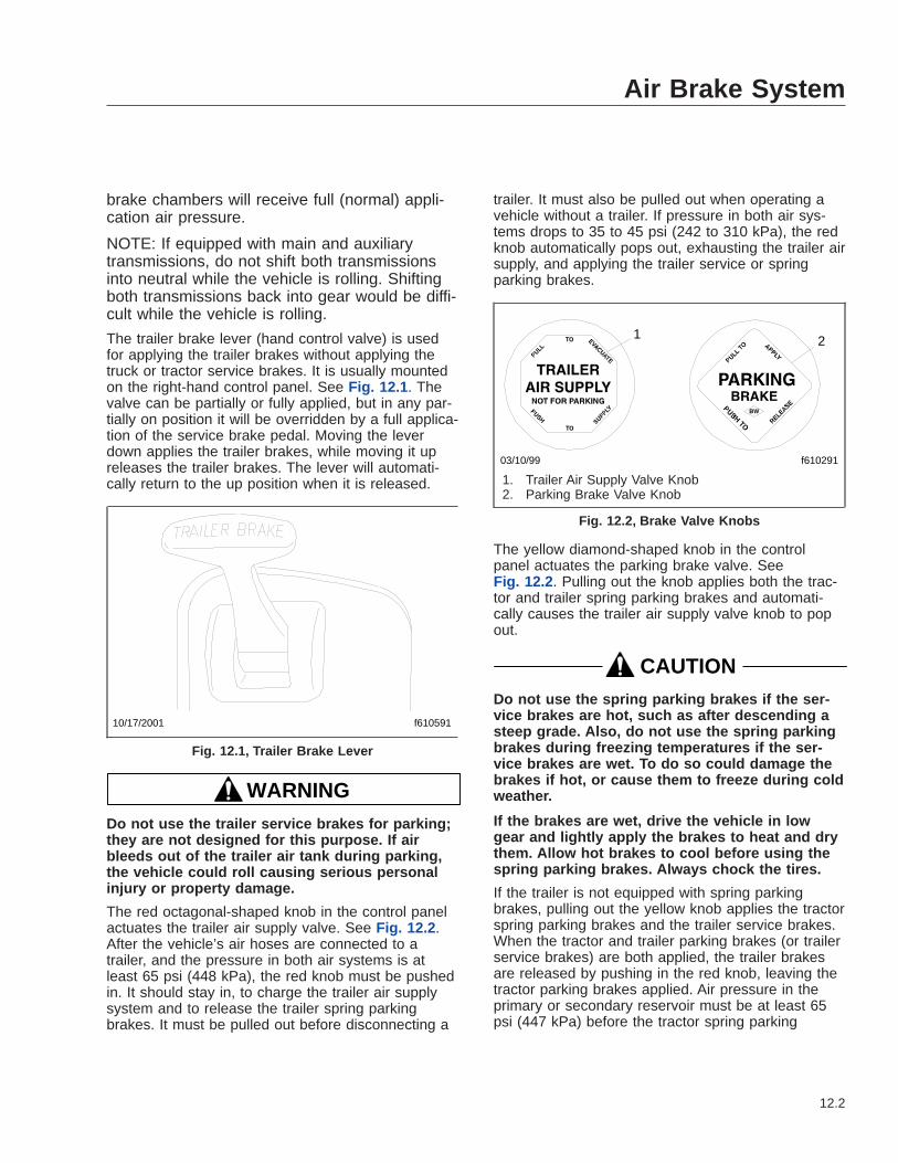
brake chambers will receive full (normal) appli-cation air pressure.
NOTE: If equipped with main and auxiliarytransmissions, do not shift both transmissionsinto neutral while the vehicle is rolling. Shiftingboth transmissions back into gear would be diffi-cult while the vehicle is rolling.
The trailer brake lever (hand control valve) is usedfor applying the trailer brakes without applying thetruck or tractor service brakes. It is usually mountedon the right-hand control panel. See Fig. 12.1 . Thevalve can be partially or fully applied, but in any par-tially on position it will be overridden by a full applica-tion of the service brake pedal. Moving the leverdown applies the trailer brakes, while moving it upreleases the trailer brakes. The lever will automati-cally return to the up position when it is released.
WARNINGDo not use the trailer service brakes for parking;they are not designed for this purpose. If airbleeds out of the trailer air tank during parking,the vehicle could roll causing serious personalinjury or property damage.
The red octagonal-shaped knob in the control panelactuates the trailer air supply valve. See Fig. 12.2 .After the vehicle’s air hoses are connected to atrailer, and the pressure in both air systems is atleast 65 psi (448 kPa), the red knob must be pushedin. It should stay in, to charge the trailer air supplysystem and to release the trailer spring parkingbrakes. It must be pulled out before disconnecting a
trailer. It must also be pulled out when operating avehicle without a trailer. If pressure in both air sys-tems drops to 35 to 45 psi (242 to 310 kPa), the redknob automatically pops out, exhausting the trailer airsupply, and applying the trailer service or springparking brakes.
The yellow diamond-shaped knob in the controlpanel actuates the parking brake valve. SeeFig. 12.2 . Pulling out the knob applies both the trac-tor and trailer spring parking brakes and automati-cally causes the trailer air supply valve knob to popout.
CAUTIONDo not use the spring parking brakes if the ser-vice brakes are hot, such as after descending asteep grade. Also, do not use the spring parkingbrakes during freezing temperatures if the ser-vice brakes are wet. To do so could damage thebrakes if hot, or cause them to freeze during coldweather.
If the brakes are wet, drive the vehicle in lowgear and lightly apply the brakes to heat and drythem. Allow hot brakes to cool before using thespring parking brakes. Always chock the tires.
If the trailer is not equipped with spring parkingbrakes, pulling out the yellow knob applies the tractorspring parking brakes and the trailer service brakes.When the tractor and trailer parking brakes (or trailerservice brakes) are both applied, the trailer brakesare released by pushing in the red knob, leaving thetractor parking brakes applied. Air pressure in theprimary or secondary reservoir must be at least 65psi (447 kPa) before the tractor spring parking
10/17/2001 f610591
Fig. 12.1, Trailer Brake Lever
f610291
1 2
03/10/99
1. Trailer Air Supply Valve Knob2. Parking Brake Valve Knob
Fig. 12.2, Brake Valve Knobs
Air Brake System
12.2
brakes, or the trailer service or spring parkingbrakes, can be released.
On trailers not equipped with spring parking brakes,chock the trailer tires before disconnecting the truckor tractor when parking just the trailer.
When parking a truck or tractor with a trailer (combi-nation vehicle), and the trailer is not equipped withspring parking brakes, apply the truck or tractorspring parking brakes.
WARNINGIf a trailer is not equipped with spring parkingbrakes, do not park it or a combination vehicleby pulling out only the trailer air supply valveknob. This would apply only the trailer servicebrakes. If air were to bleed from the trailer brakesystem, the trailer brakes would release, possiblycausing an unattended runaway vehicle.
CAUTIONNever apply the service and spring parkingbrakes simultaneously. To do so transmits exces-sive input force to the brake components, whichcould damage or cause eventual failure of brakeactuating components.
Automatic Slack AdjustersAutomatic slack adjusters should never be manuallyadjusted except during routine maintenance of thefoundation brakes (e.g., replacing shoes), duringslack adjuster installation, or in an emergency situa-tion.
When the brake pushrod stroke exceeds the legalbrake adjustment limit on a vehicle, there is likely amechanical problem with the foundation brake com-ponents or the adjuster is improperly installed.
Visit a repair facility as soon as possible whenbrakes equipped with automatic slack adjusters aredetermined to be out of adjustment.
WARNINGManually adjusting an automatic slack adjuster tobring the pushrod stroke within legal limits islikely masking a mechanical problem. Adjustmentis not repairing. In fact, continual adjustment ofautomatic slack adjusters may result in prema-
ture wear of the adjuster itself. Further, the im-proper adjustment of some automatic slack ad-justers may cause internal damage to theadjuster, thereby preventing it from properlyfunctioning.
Meritor WABCO ® AntilockBraking System (ABS)The Meritor WABCO Antilock Braking System (ABS)is an electronic wheel speed monitoring and controlsystem that works with the standard air brake sys-tem. ABS passively monitors vehicle wheel speed atall times, and controls wheel speed during emer-gency stops. If equipped with Automatic TractionControl, wheel spin is controlled during reduced-traction situations. In normal braking applications, thestandard air brake system is in effect.
IMPORTANT: For proper ABS system operation,do not change tire sizes. The sizes of the tiresinstalled during production are programmed intothe electronic control unit. Installing different-sized tires could result in a reduced brakingforce, leading to longer stopping distances.
ABS includes signal-generating tone wheels and sen-sors located in the wheel hubs of each sensedwheel. The sensors transmit vehicle wheel speedinformation to an electronic control unit (located be-hind the center dash). The control unit’s main circuitinterprets the speed sensor signals and calculateswheel speed, wheel retardation, and a vehicle refer-ence speed. If the calculations indicate wheel lockup,the main circuit signals the appropriate modulatorvalve to reduce braking pressure. During emergencybraking, the modulator valve alternately reduces, in-creases, or maintains air pressure supply in thebrake chamber to prevent front and rear wheellockup.
If equipped with automatic traction control (ATC), anadditional solenoid valve is installed. During reduced-traction situations, the ATC solenoid valve controlsair pressure to the modulator valves, and they in turnincrease, hold, or reduce pressure to the appropriatebrake chambers to provide better traction wheneverwheel spin occurs.
The electronic control unit also has a safety circuitthat constantly monitors the wheel sensors, tractioncontrol valve (if equipped), modulator valves, and theelectrical circuitry.
Air Brake System
12.3
After the ignition switch is turned on, the tractorwarning light (TRACTOR ABS) and, if equipped withautomatic traction control, the wheel spin indicatorlight come on for about three seconds. After threeseconds, the warning lights go out only if all of thetractor’s ABS components are working.
Vehicles with electronic engines and ABS may haveATC. On these vehicles, the ATC system automati-cally limits wheel spin during reduced-traction situa-tions.
If the vehicle has ATC, there will be a momentarycontact rocker switch on the dash labeled ATC.
When the ATC system is in the NORMAL mode, itwill apply gentle braking to the spinning wheel, tofeed power to the wheel(s) with better traction. Ifboth wheels are spinning, the system will signal theelectronic engine to reduce power.
Pressing the switch will temporarily allow more drivewheel spin to help burn through a thin layer of ice, orto help throw off accumulated mud or snow. SPINmode is indicated by a flashing WHEEL SPIN light.Pressing the switch again will cycle the system backto normal operation.
The Meritor WABCO ABS system combines onefront-axle control channel with one rear axle to formone control circuit. For example, the sensor andmodulator valve on the left-front axle form a controlcircuit with the sensor and modulator valve on theright rear axle. If, during vehicle operation, the safetycircuit senses a failure in any part of the ABS system(a sensor, modulator valve, wiring connection, shortcircuit, etc.), the tractor warning light (TRACTORABS) comes on and the control circuit where the fail-ure occurred is switched to normal braking action.The remaining control circuit will retain the ABS ef-fect. Even if the ABS system is completely inopera-tive, normal braking ability is maintained. An excep-tion would be if a modulator valve (or combinationmodulator valve) is damaged and inoperative. Asthese components are an integral part of the airbrake system, normal braking may be impaired orinoperative.
IMPORTANT: If any of the ABS warning lightsdo not work as described above, or come onwhile driving, repair the ABS system immedi-ately to ensure full antilock braking capability.
During emergency or reduced-traction stops, fullydepress the brake pedal until the vehicle comes to a
safe stop; do not pump the brake pedal. With thebrake pedal fully depressed, the ABS system willcontrol all wheels to provide steering control and areduced braking distance.
Although the ABS system improves vehicle controlduring emergency braking situations, the driver stillhas the responsibility to change driving styles de-pending on the existing traffic and road conditions.For example, the ABS system cannot prevent an ac-cident if the driver is speeding or following tooclosely.
Trailer ABS Lamp OperationAntilock Braking Systems (ABS) on tractors are de-signed to communicate with trailer ABS systems, ifthey are compatible. Compatibility will result in theillumination of the trailer ABS lamp during vehiclestart-up and fault detection.
The dash-mounted lamp will operate as follows whena compatible trailer is properly connected to a tractor:
• When the ignition key is turned to the ON posi-tion, the trailer ABS lamp will illuminate mo-mentarily, then turn off.
• If the lamp comes on momentarily during ve-hicle operation, then shuts off, a fault was de-tected and corrected.
• If the lamp comes on and stays on during ve-hicle operation, there is a fault with the trailerABS. Repair the trailer ABS system immedi-ately to ensure full antilock braking capability.
The Trailer ABS lamp will not illuminate unless acompatible trailer is connected to the tractor.
IMPORTANT: If a compatible trailer is con-nected, and the lamp is not illuminating momen-tarily when the ignition key is turned to the ONposition, it is possible that the lamp is burnt out.
Air Brake System
12.4
13
Engine BrakesEngine Brake . . . . . . . . . . . . . . . . . . . . . . . . . . . . . . . . . . . . . . . . . . . . . . . . . . . . . . . . . . . . . . . . . . . 13.1
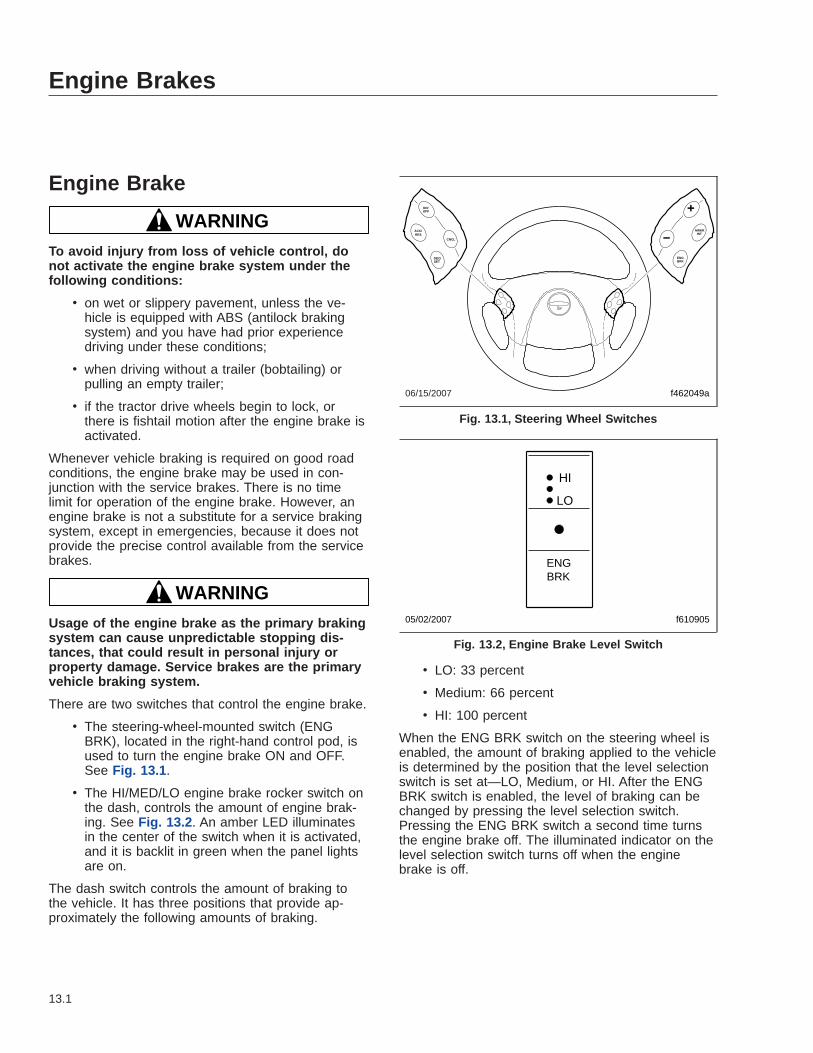
Engine Brake
WARNINGTo avoid injury from loss of vehicle control, donot activate the engine brake system under thefollowing conditions:
• on wet or slippery pavement, unless the ve-hicle is equipped with ABS (antilock brakingsystem) and you have had prior experiencedriving under these conditions;
• when driving without a trailer (bobtailing) orpulling an empty trailer;
• if the tractor drive wheels begin to lock, orthere is fishtail motion after the engine brake isactivated.
Whenever vehicle braking is required on good roadconditions, the engine brake may be used in con-junction with the service brakes. There is no timelimit for operation of the engine brake. However, anengine brake is not a substitute for a service brakingsystem, except in emergencies, because it does notprovide the precise control available from the servicebrakes.
WARNINGUsage of the engine brake as the primary brakingsystem can cause unpredictable stopping dis-tances, that could result in personal injury orproperty damage. Service brakes are the primaryvehicle braking system.
There are two switches that control the engine brake.
• The steering-wheel-mounted switch (ENGBRK), located in the right-hand control pod, isused to turn the engine brake ON and OFF.See Fig. 13.1 .
• The HI/MED/LO engine brake rocker switch onthe dash, controls the amount of engine brak-ing. See Fig. 13.2 . An amber LED illuminatesin the center of the switch when it is activated,and it is backlit in green when the panel lightsare on.
The dash switch controls the amount of braking tothe vehicle. It has three positions that provide ap-proximately the following amounts of braking.
• LO: 33 percent
• Medium: 66 percent
• HI: 100 percent
When the ENG BRK switch on the steering wheel isenabled, the amount of braking applied to the vehicleis determined by the position that the level selectionswitch is set at—LO, Medium, or HI. After the ENGBRK switch is enabled, the level of braking can bechanged by pressing the level selection switch.Pressing the ENG BRK switch a second time turnsthe engine brake off. The illuminated indicator on thelevel selection switch turns off when the enginebrake is off.
06/15/2007
ON/OFF
ACC/RES
CNCL
DEC/SET
MRKRINT
ENGBRK
−
+
f462049a
Fig. 13.1, Steering Wheel Switches
ENGBRK
f61090505/02/2007
HI
LO
Fig. 13.2, Engine Brake Level Switch
Engine Brakes
13.1
WARNINGThe engine brake must be disengaged whenshifting gears, by using the clutch. If the enginebrake is engaged when the transmission is inneutral, the braking power of the engine brakecan stall the engine, which could result in loss ofvehicle control, possibly causing personal injuryand property damage.
On a cold engine, below a set engine temperature,the brake may be disabled, depending on the braketype. The engine brake may be activated after theengine is warmed up and the vehicle is in motion,using the following procedures.
• Remove your feet from both the clutch andthrottle pedals. Press the steering-wheel-mounted switch to toggle the engine brake ON.See Fig. 13.1 .
The engine brake will engage at the rate lastset on the dash switch (HI/MED/LO). SeeFig. 13.2 .
• Move the dash switch to the desired rate, HIfor 100% braking capacity, MED for 66% brak-ing capacity, or LO for 32% braking capacity.
Use the dash-mounted switch set at the LOposition when driving on flat, open stretches ofroad. If the service brakes are still required toslow down on a grade, switch to a higher set-ting on the dash switch, until there is no needfor the service brakes. Grade descent speedshould be such that the service brakes areused infrequently and that they remain cool,thus retaining their effectiveness.
• To obtain maximum retarding, maintain the topgoverned speed of the engine through the ap-propriate selection of gears. When shiftinggears, the engine brake will disengage whenthe clutch pedal is depressed, then engagewhen the clutch pedal is released.
• To cancel the engine brake application, pressthe steering-wheel-mounted switch to toggle itto OFF.
• If the engine brake fails to activate, take thevehicle to an authorized Freightliner dealer forservice.
Since the engine brake is most effective at rated en-gine speed, gear selection is very important. Gearing
down the vehicle, within the limits of the rated enginespeed, makes the engine brake more effective. Rec-ommended engine braking speed is above 1800 rpmand below the rated speed.
NOTICEDo not allow the engine to exceed 2500 rpm. Se-rious engine damage could result.
"Control speed" is the speed at which the enginebrake performs 100 percent of the required downhillbraking, resulting in a constant speed of descent.The control speed varies, depending on vehicleweight and the downhill grade.For faster descent,select a higher gear than that used for control speed.Service brakes must then be used intermittently toprevent engine overspeed and to maintain desiredvehicle speed.A driver may descend slower than con-trol speed by selecting a lower gear, being carefulnot to overspeed the engine. Occasional deactivationof the engine brake may be necessary to maintainthe designated road speed under these conditions.
If the engine is equipped with both cruise control andan engine brake, the engine brake can operate auto-matically while in cruise control mode. If the cruisecontrol/engine brake function is turned on in theDDEC VI system programming, the engine brake willcome on "low" when the set road speed increases afew miles-per-hour (kilometers-per-hour) above thecruise set speed. The maximum amount of braking(low, medium, high) is selected with the dashswitches. When the vehicle returns to the set cruisespeed, the engine brake will turn off.
The engine brake will only operate when the accel-erator pedal is fully released. Disengaging the clutchwill prevent the engine brake from operating.
Vehicles equipped with antilock braking systems(ABS) have the ability to turn the engine brake off ifa wheel-slip condition is detected. The engine brakewill automatically turn itself back on once the wheelslip is no longer detected. The DDEC VI system willdeactivate the engine brake system when the enginespeed falls below 1000 rpm or when the vehicleslows down to a preset speed, depending on DDECprogramming. This prevents stalling the engine.
Engine Brakes
13.2
14
Manual Transmissions andHydraulic Clutch
Eaton Fuller 13-Speed and 18-Speed Splitter and Range-Shift Transmissions . . . . . . . . . . . . . . . 14.1Eaton Fuller 10-Speed Range-Shift Transmissions . . . . . . . . . . . . . . . . . . . . . . . . . . . . . . . . . . . . . 14.4Clutch . . . . . . . . . . . . . . . . . . . . . . . . . . . . . . . . . . . . . . . . . . . . . . . . . . . . . . . . . . . . . . . . . . . . . . . . . 14.5
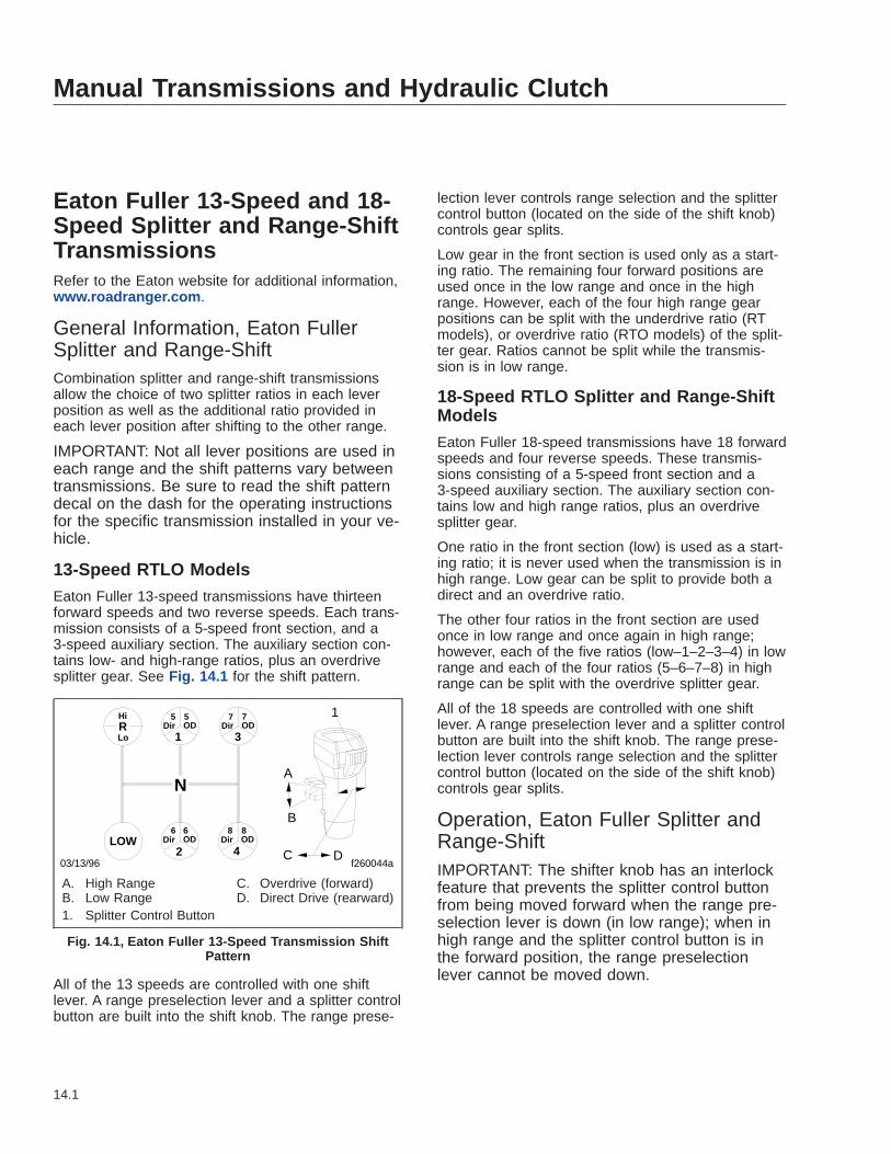
Eaton Fuller 13-Speed and 18-Speed Splitter and Range-ShiftTransmissionsRefer to the Eaton website for additional information,www.roadranger.com .
General Information, Eaton FullerSplitter and Range-ShiftCombination splitter and range-shift transmissionsallow the choice of two splitter ratios in each leverposition as well as the additional ratio provided ineach lever position after shifting to the other range.
IMPORTANT: Not all lever positions are used ineach range and the shift patterns vary betweentransmissions. Be sure to read the shift patterndecal on the dash for the operating instructionsfor the specific transmission installed in your ve-hicle.
13-Speed RTLO ModelsEaton Fuller 13-speed transmissions have thirteenforward speeds and two reverse speeds. Each trans-mission consists of a 5-speed front section, and a3-speed auxiliary section. The auxiliary section con-tains low- and high-range ratios, plus an overdrivesplitter gear. See Fig. 14.1 for the shift pattern.
All of the 13 speeds are controlled with one shiftlever. A range preselection lever and a splitter controlbutton are built into the shift knob. The range prese-
lection lever controls range selection and the splittercontrol button (located on the side of the shift knob)controls gear splits.
Low gear in the front section is used only as a start-ing ratio. The remaining four forward positions areused once in the low range and once in the highrange. However, each of the four high range gearpositions can be split with the underdrive ratio (RTmodels), or overdrive ratio (RTO models) of the split-ter gear. Ratios cannot be split while the transmis-sion is in low range.
18-Speed RTLO Splitter and Range-ShiftModelsEaton Fuller 18-speed transmissions have 18 forwardspeeds and four reverse speeds. These transmis-sions consisting of a 5-speed front section and a3-speed auxiliary section. The auxiliary section con-tains low and high range ratios, plus an overdrivesplitter gear.
One ratio in the front section (low) is used as a start-ing ratio; it is never used when the transmission is inhigh range. Low gear can be split to provide both adirect and an overdrive ratio.
The other four ratios in the front section are usedonce in low range and once again in high range;however, each of the five ratios (low–1–2–3–4) in lowrange and each of the four ratios (5–6–7–8) in highrange can be split with the overdrive splitter gear.
All of the 18 speeds are controlled with one shiftlever. A range preselection lever and a splitter controlbutton are built into the shift knob. The range prese-lection lever controls range selection and the splittercontrol button (located on the side of the shift knob)controls gear splits.
Operation, Eaton Fuller Splitter andRange-ShiftIMPORTANT: The shifter knob has an interlockfeature that prevents the splitter control buttonfrom being moved forward when the range pre-selection lever is down (in low range); when inhigh range and the splitter control button is inthe forward position, the range preselectionlever cannot be moved down.
R1 3
2 4LOW
Dir OD5 5
Dir OD
Dir OD Dir OD
7 7
6 6 8 8
Hi
Lo
A
B
C D
1
03/13/96 f260044a
N
A. High RangeB. Low Range
C. Overdrive (forward)D. Direct Drive (rearward)
1. Splitter Control Button
Fig. 14.1, Eaton Fuller 13-Speed Transmission ShiftPattern
Manual Transmissions and Hydraulic Clutch
14.1
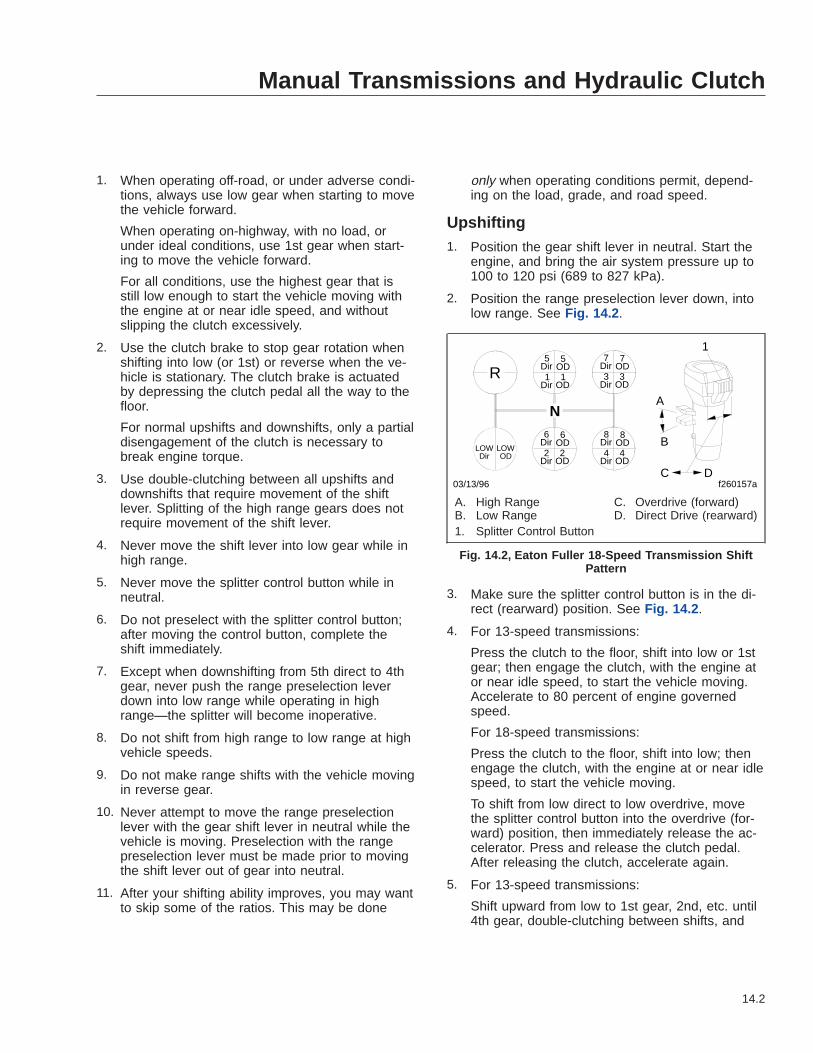
1. When operating off-road, or under adverse condi-tions, always use low gear when starting to movethe vehicle forward.
When operating on-highway, with no load, orunder ideal conditions, use 1st gear when start-ing to move the vehicle forward.
For all conditions, use the highest gear that isstill low enough to start the vehicle moving withthe engine at or near idle speed, and withoutslipping the clutch excessively.
2. Use the clutch brake to stop gear rotation whenshifting into low (or 1st) or reverse when the ve-hicle is stationary. The clutch brake is actuatedby depressing the clutch pedal all the way to thefloor.
For normal upshifts and downshifts, only a partialdisengagement of the clutch is necessary tobreak engine torque.
3. Use double-clutching between all upshifts anddownshifts that require movement of the shiftlever. Splitting of the high range gears does notrequire movement of the shift lever.
4. Never move the shift lever into low gear while inhigh range.
5. Never move the splitter control button while inneutral.
6. Do not preselect with the splitter control button;after moving the control button, complete theshift immediately.
7. Except when downshifting from 5th direct to 4thgear, never push the range preselection leverdown into low range while operating in highrange—the splitter will become inoperative.
8. Do not shift from high range to low range at highvehicle speeds.
9. Do not make range shifts with the vehicle movingin reverse gear.
10. Never attempt to move the range preselectionlever with the gear shift lever in neutral while thevehicle is moving. Preselection with the rangepreselection lever must be made prior to movingthe shift lever out of gear into neutral.
11. After your shifting ability improves, you may wantto skip some of the ratios. This may be done
only when operating conditions permit, depend-ing on the load, grade, and road speed.
Upshifting1. Position the gear shift lever in neutral. Start the
engine, and bring the air system pressure up to100 to 120 psi (689 to 827 kPa).
2. Position the range preselection lever down, intolow range. See Fig. 14.2 .
3. Make sure the splitter control button is in the di-rect (rearward) position. See Fig. 14.2 .
4. For 13-speed transmissions:
Press the clutch to the floor, shift into low or 1stgear; then engage the clutch, with the engine ator near idle speed, to start the vehicle moving.Accelerate to 80 percent of engine governedspeed.
For 18-speed transmissions:
Press the clutch to the floor, shift into low; thenengage the clutch, with the engine at or near idlespeed, to start the vehicle moving.
To shift from low direct to low overdrive, movethe splitter control button into the overdrive (for-ward) position, then immediately release the ac-celerator. Press and release the clutch pedal.After releasing the clutch, accelerate again.
5. For 13-speed transmissions:
Shift upward from low to 1st gear, 2nd, etc. until4th gear, double-clutching between shifts, and
N
R 1Dir
5Dir
5OD1
OD3
Dir
7Dir
7OD3
OD
2Dir
6Dir
6OD2
OD4
Dir
8Dir
8OD4
ODLOWDir
LOWOD
A
B
C D
1
03/13/96 f260157a
A. High RangeB. Low Range
C. Overdrive (forward)D. Direct Drive (rearward)
1. Splitter Control Button
Fig. 14.2, Eaton Fuller 18-Speed Transmission ShiftPattern
Manual Transmissions and Hydraulic Clutch
14.2
accelerating to 80 percent of engine governedspeed. See Fig. 14.1 .
For 18-speed transmissions:
Shift upward from low overdrive to 1st direct byfirst moving the splitter control button into thedirect (rearward) position (Fig. 14.2 ). Move theshift lever, double-clutching, to the 1st gear posi-tion.
Continue upshifting through the shift pattern.Double-clutch during lever shifts (1st to 2nd to3rd to 4th); single-clutch during split shifts (1stdirect to 1st overdrive, etc.).
6. When in 4th gear (13-speed transmissions) or4th overdrive (18-speed transmissions) andready to shift up to 5th gear, use the range shiftlever as follows:
For 13-speed transmissions:
While in 4th gear, pull the range shift preselec-tion lever up, into high range. The transmissionwill automatically shift from low to high range asthe shift lever passes through neutral. Then, dis-engage the clutch; double-clutch through neutral;move the shift lever to 5th gear; engage theclutch, and accelerate the engine.
For 18-speed transmissions:
While in 4th overdrive, pull the range shift prese-lection lever up, into high range. The transmis-sion will automatically shift from low to highrange as the shift lever passes through neutral.
Move the shift lever, double-clutching, to the 5thgear position. Just before making final clutch en-gagement, move the splitter control button to thedirect (rearward) position; then engage the clutchand accelerate. Do not move the control buttonwhile the shift lever is in neutral.
7. Shift up through the high range gears as follows:
For 13-speed transmissions:
To shift from 5th direct to 5th overdrive, move thesplitter control button (Fig. 14.1 ) into the over-drive (forward) position, then immediately releasethe accelerator. Press and release the clutchpedal. After releasing the clutch, accelerateagain.
Continue upshifting through the shift pattern.Double-clutch during lever shifts (6th to 7th to
8th); single-clutch during split shifts (6th direct to6th overdrive, etc.).
For 18-speed transmissions:
To shift from 5th direct to 5th overdrive, move thesplitter control button (Fig. 14.2 ) into the over-drive (forward) position, then immediately releasethe accelerator. Press and release the clutchpedal. After releasing the clutch, accelerateagain.
Continue upshifting through the shift pattern.Double-clutch during lever shifts (6th to 7th to8th); single-clutch during split shifts (6th direct to6th overdrive, etc.).
Downshifting1. Downshift from 8th overdrive to 8th direct without
moving the shift lever. Flip the splitter control but-ton to the direct (rearward) position, then imme-diately release the accelerator, and disengagethe clutch. Engage the clutch, and accelerate theengine only after the transmission has shifted.
2. Start the downshift from 8th direct to 7th over-drive by flipping the splitter control button to theoverdrive (forward) position; then, immediatelydouble-clutch through neutral, moving the shiftlever from 8th to 7th gear.
3. Shift downward through each of the high rangegears, alternating the procedures in steps 1 and2, above, until reaching 5th direct.
4. While in 5th direct and ready for the downshift to4th (13-speed transmissions) or 4th overdrive(18-speed transmissions), push the range prese-lection lever down. Then, double-clutch throughneutral and move the shift lever to the 4th gearposition. On 18-speed transmissions, move thesplitter control button to the overdrive (forward)position beforeengaging the clutch. Do not movethe control button while the shift lever is in neu-tral.
5. Continue downshifting from 4th to 1st as follows:
For 13-speed transmissions:
Downshift through the low range gears as condi-tions require.
For 18-speed transmissions:
Manual Transmissions and Hydraulic Clutch
14.3
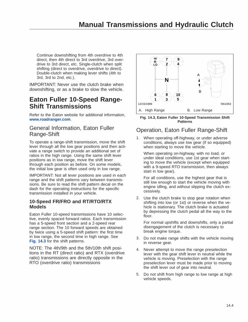
Continue downshifting from 4th overdrive to 4thdirect, then 4th direct to 3rd overdrive, 3rd over-drive to 3rd direct, etc. Single-clutch when splitshifting (direct to overdrive, overdrive to direct).Double-clutch when making lever shifts (4th to3rd, 3rd to 2nd, etc.).
IMPORTANT: Never use the clutch brake whendownshifting, or as a brake to slow the vehicle.
Eaton Fuller 10-Speed Range-Shift TransmissionsRefer to the Eaton website for additional information,www.roadranger.com .
General Information, Eaton FullerRange-ShiftTo operate a range-shift transmission, move the shiftlever through all the low gear positions and then acti-vate a range switch to provide an additional set ofratios in the high range. Using the same shift leverpositions as in low range, move the shift leverthrough each position as before. On some models,the initial low gear is often used only in low range.
IMPORTANT: Not all lever positions are used in eachrange and the shift patterns vary between transmis-sions. Be sure to read the shift pattern decal on thedash for the operating instructions for the specifictransmission installed in your vehicle.
10-Speed FR/FRO and RT/RTO/RTXModelsEaton Fuller 10-speed transmissions have 10 selec-tive, evenly spaced forward ratios. Each transmissionhas a 5-speed front section and a 2-speed rearrange section. The 10 forward speeds are obtainedby twice using a 5-speed shift pattern: the first timein low range, the second time in high range. SeeFig. 14.3 for the shift patterns.
NOTE: The 4th/9th and the 5th/10th shift posi-tions in the RT (direct ratio) and RTX (overdriveratio) transmissions are directly opposite in theRTO (overdrive ratio) transmissions
Operation, Eaton Fuller Range-Shift1. When operating off-highway, or under adverse
conditions, always use low gear (if so equipped)when starting to move the vehicle.
When operating on-highway, with no load, orunder ideal conditions, use 1st gear when start-ing to move the vehicle (except when equippedwith a 9-speed RTO transmission, then alwaysstart in low gear).
For all conditions, use the highest gear that isstill low enough to start the vehicle moving withengine idling, and without slipping the clutch ex-cessively.
2. Use the clutch brake to stop gear rotation whenshifting into low (or 1st) or reverse when the ve-hicle is stationary. The clutch brake is actuatedby depressing the clutch pedal all the way to thefloor.
For normal upshifts and downshifts, only a partialdisengagement of the clutch is necessary tobreak engine torque.
3. Do not make range shifts with the vehicle movingin reverse gear.
4. Never attempt to move the range preselectionlever with the gear shift lever in neutral while thevehicle is moving. Preselection with the rangepreselection lever must be made prior to movingthe shift lever out of gear into neutral.
5. Do not shift from high range to low range at highvehicle speeds.
4
N
7 2
9
6 1
8 3
10 5
R HI
LO
f261053
A
B
12/15/1999
A. High Range B. Low Range
Fig. 14.3, Eaton Fuller 10-Speed Transmission ShiftPatterns
Manual Transmissions and Hydraulic Clutch
14.4
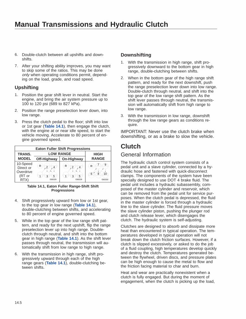
6. Double-clutch between all upshifts and down-shifts.
7. After your shifting ability improves, you may wantto skip some of the ratios. This may be doneonly when operating conditions permit, depend-ing on the load, grade, and road speed.
Upshifting1. Position the gear shift lever in neutral. Start the
engine, and bring the air system pressure up to100 to 120 psi (689 to 827 kPa).
2. Position the range preselection lever down, intolow range.
3. Press the clutch pedal to the floor; shift into lowor 1st gear (Table 14.1 ), then engage the clutch,with the engine at or near idle speed, to start thevehicle moving. Accelerate to 80 percent of en-gine governed speed.
Eaton Fuller Shift Progressions
TRANS.MODEL
LOW RANGE HIGHRANGEOff-Highway On-Highway
10-SpeedDirect orOverdrive
(RT orRTX)
2
3
4
1
f260329
R
5
2
3
4
1
f260329
R
5
9
8 10
7
f260330
R
6
Table 14.1, Eaton Fuller Range-Shift ShiftProgressions
4. Shift progressively upward from low or 1st gear,to the top gear in low range (Table 14.1 ),double-clutching between shifts, and acceleratingto 80 percent of engine governed speed.
5. While in the top gear of the low range shift pat-tern, and ready for the next upshift, flip the rangepreselection lever up into high range. Double-clutch through neutral, and shift into the bottomgear in high range (Table 14.1 ). As the shift leverpasses through neutral, the transmission will au-tomatically shift from low range to high range.
6. With the transmission in high range, shift pro-gressively upward through each of the highrange gears (Table 14.1 ), double-clutching be-tween shifts.
Downshifting1. With the transmission in high range, shift pro-
gressively downward to the bottom gear in highrange, double-clutching between shifts.
2. When in the bottom gear of the high range shiftpattern, and ready for the next downshift, pushthe range preselection lever down into low range.Double-clutch through neutral, and shift into thetop gear of the low range shift pattern. As theshift lever passes through neutral, the transmis-sion will automatically shift from high range tolow range.
3. With the transmission in low range, downshiftthrough the low range gears as conditions re-quire.
IMPORTANT: Never use the clutch brake whendownshifting, or as a brake to slow the vehicle.
ClutchGeneral InformationThe hydraulic clutch control system consists of apedal unit and a slave cylinder, connected by a hy-draulic hose and fastened with quick-disconnectclamps. The components of the system have beenspecially designed to use DOT 4 brake fluid. Thepedal unit includes a hydraulic subassembly, com-posed of the master cylinder and reservoir, whichcan be removed from the pedal unit for service pur-poses. When the clutch pedal is depressed, the fluidin the master cylinder is forced through a hydraulicline to the slave cylinder. The fluid pressure movesthe slave cylinder piston, pushing the plunger rodand clutch release lever, which disengages theclutch. The hydraulic system is self-adjusting.
Clutches are designed to absorb and dissipate moreheat than encountered in typical operation. The tem-peratures developed in typical operation will notbreak down the clutch friction surfaces. However, if aclutch is slipped excessively, or asked to do the jobof a fluid coupling, high temperatures develop quicklyand destroy the clutch. Temperatures generated be-tween the flywheel, driven discs, and pressure platescan be high enough to cause the metal to flow andthe friction facing material to char and burn.
Heat and wear are practically nonexistent when aclutch is fully engaged. But during the moment ofengagement, when the clutch is picking up the load,
Manual Transmissions and Hydraulic Clutch
14.5
it generates considerable heat. An improperly ad-justed or slipping clutch will rapidly generate suffi-cient heat to destroy itself.
To ensure long service life of the clutch; start in theright gear, be alert to clutch malfunctions, and knowwhen to adjust the clutch.
Clutch OperationClutch Break-InWith a new or newly installed clutch, the clutch mayslip for a short time while the friction surfaces break-in. However, allowing the clutch to slip for more thantwo seconds can severely damage the clutch disc,pressure plate, and the flywheel.
During initial operation of a new vehicle or a vehiclewith a new clutch, check for clutch slippage duringacceleration. If the clutch slips, decelerate until theclutch does not slip. Allow the clutch to cool 15 to 30seconds, and then gradually accelerate again. If theclutch continues to slip, repeat the procedure. If nec-essary, repeat the procedure up to five times. If theclutch slips after five attempts, stop the vehicle. Allowthe clutch to cool for at least one hour. Notify yourFreightliner dealer of the problem.
CAUTIONDo not allow sustained slippage of the clutch;this could severely damage the clutch disc, pres-sure plate, or flywheel. Damage caused by clutchslippage due to improper break-in is not warrant-able.
Moving the Vehicle in the Proper GearAn empty truck can be started in a higher transmis-sion gear than can a partially or fully loaded truck. Agood rule of thumb for the driver to follow is to selectthe gear combination that allows the vehicle to startmoving with an idling engine, or, if necessary, justenough throttle to prevent stalling the engine. Afterthe clutch is fully engaged, the engine can be accel-erated to the correct rpm for the upshift into the nexthigher gear.
Gear Shifting TechniquesShift into the next higher gear when the vehiclespeed allows the transmission input shaft speed tomatch the flywheel speed when engaging the clutch.This technique results in the smallest speed differ-
ence between the clutch disc and the flywheel andcauses the least heat and wear on the clutch assem-bly. When downshifting, the input shaft speed mustbe increased by slightly revving the engine to matchthe flywheel speed for smooth clutch engagement.For transmission operating instructions, refer to thetransmission headings in this manual.
Vehicle LoadingClutches are designed for specific vehicle applica-tions and loads. These weight limitations should notbe exceeded.
CAUTIONExceeding vehicle load limits can not only resultin damage to the clutch, but can also damage theentire powertrain.
Using the ClutchThe clutch pedal must be used only to start the ve-hicle moving or while shifting. To start the vehiclemoving, depress the clutch pedal all the way to thefloor plate (see "Using the Clutch Brake") and shiftfrom neutral to a low gear. Slowly raise your foot untilthe clutch starts to engage. In this position the clutchis starting to connect the transmission input shaft tothe flywheel and is causing the most heat and wear.Slightly increase the engine speed and smoothlyallow the clutch pedal to return to its at rest position.Do not allow the clutch to remain in the partially en-gaged position any longer than necessary to obtain asmooth start.
To shift gears while the vehicle is moving, push theclutch pedal most of the way (but not all of the way)to the floor plate. Shift the transmission into neutraland fully release the clutch pedal. If upshifting, waitlong enough for the engine speed to decrease to theroad speed. If downshifting, increase the enginespeed to match the road speed. Again, push downthe clutch pedal part way and then move the shiftlever to the next gear position. Fully release theclutch pedal after completing the shift.
Slightly depressing the clutch pedal while driving isdamaging to the clutch, because partial clutch en-gagement causes slippage and heat. Resting yourfoot on the clutch pedal will also put a constant thrustload on the release bearing, thinning the bearing lu-bricant and increasing the wear on the bearing.
Manual Transmissions and Hydraulic Clutch
14.6
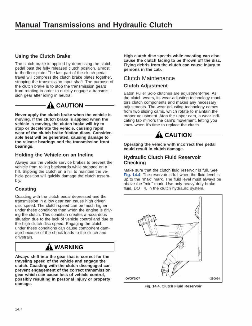
Using the Clutch BrakeThe clutch brake is applied by depressing the clutchpedal past the fully released clutch position, almostto the floor plate. The last part of the clutch pedaltravel will compress the clutch brake plates together,stopping the transmission input shaft. The purpose ofthe clutch brake is to stop the transmission gearsfrom rotating in order to quickly engage a transmis-sion gear after idling in neutral.
CAUTIONNever apply the clutch brake when the vehicle ismoving. If the clutch brake is applied when thevehicle is moving, the clutch brake will try tostop or decelerate the vehicle, causing rapidwear of the clutch brake friction discs. Consider-able heat will be generated, causing damage tothe release bearings and the transmission frontbearings.
Holding the Vehicle on an InclineAlways use the vehicle service brakes to prevent thevehicle from rolling backwards while stopped on ahill. Slipping the clutch on a hill to maintain the ve-hicle position will quickly damage the clutch assem-bly.
CoastingCoasting with the clutch pedal depressed and thetransmission in a low gear can cause high drivendisc speed. The clutch speed can be much higherunder these conditions than when the engine is driv-ing the clutch. This condition creates a hazardoussituation due to the lack of vehicle control and due tothe high clutch disc speed. Engaging the clutchunder these conditions can cause component dam-age because of the shock loads to the clutch anddrivetrain.
WARNINGAlways shift into the gear that is correct for thetraveling speed of the vehicle and engage theclutch. Coasting with the clutch disengaged canprevent engagement of the correct transmissiongear which can cause loss of vehicle control,possibly resulting in personal injury or propertydamage.
High clutch disc speeds while coasting can alsocause the clutch facing to be thrown off the disc.Flying debris from the clutch can cause injury topersons in the cab.
Clutch MaintenanceClutch AdjustmentEaton Fuller Solo clutches are adjustment-free. Asthe clutch wears, its wear-adjusting technology moni-tors clutch components and makes any necessaryadjustments. The wear adjusting technology comesfrom two sliding cams, which rotate to maintain theproper adjustment. Atop the upper cam, a wear indi-cating tab mirrors the cam’s movement, letting youknow when it’s time to replace the clutch.
CAUTIONOperating the vehicle with incorrect free pedalcould result in clutch damage.
Hydraulic Clutch Fluid ReservoirCheckingMake sure that the clutch fluid reservoir is full. SeeFig. 14.4 . The reservoir is full when the fluid level isup to the "max" mark. The fluid level must always beabove the "min" mark. Use only heavy-duty brakefluid, DOT 4, in the clutch hydraulic system.
06/05/2007 f250664
Fig. 14.4, Clutch Fluid Reservoir
Manual Transmissions and Hydraulic Clutch
14.7
15
Automated TransmissionsFreightliner SmartShift Shift Control . . . . . . . . . . . . . . . . . . . . . . . . . . . . . . . . . . . . . . . . . . . . . . . . . 15.1Eaton Fuller UltraShift . . . . . . . . . . . . . . . . . . . . . . . . . . . . . . . . . . . . . . . . . . . . . . . . . . . . . . . . . . . . 15.1Eaton Fuller AutoShift Automated Transmissions . . . . . . . . . . . . . . . . . . . . . . . . . . . . . . . . . . . . . . . 15.7
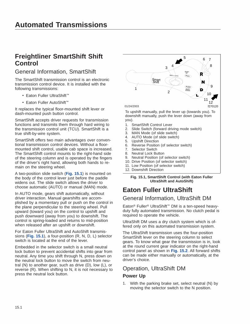
Freightliner SmartShift ShiftControlGeneral Information, SmartShiftThe SmartShift transmission control is an electronictransmission control device. It is installed with thefollowing transmissions:
• Eaton Fuller UltraShift™
• Eaton Fuller AutoShift™
It replaces the typical floor-mounted shift lever ordash-mounted push button control.
SmartShift accepts driver requests for transmissionfunctions and transmits them through hard wiring tothe transmission control unit (TCU). SmartShift is atrue shift-by-wire system.
SmartShift offers two main advantages over conven-tional transmission control devices. Without a floor-mounted shift control, usable cab space is increased.The SmartShift control mounts to the right-hand sideof the steering column and is operated by the fingersof the driver’s right hand, allowing both hands to re-main on the steering wheel.
A two-position slide switch (Fig. 15.1 ) is mounted onthe body of the control lever just before the paddlewidens out. The slide switch allows the driver tochoose automatic (AUTO) or manual (MAN) mode.
In AUTO mode, gears shift automatically, withoutdriver interaction. Manual gearshifts are accom-plished by a momentary pull or push on the control inthe plane perpendicular to the steering wheel. Pullupward (toward you) on the control to upshift andpush downward (away from you) to downshift. Thecontrol is spring-loaded and returns to mid-positionwhen released after an upshift or downshift.
For Eaton Fuller UltraShift and AutoShift transmis-sions (Fig. 15.1 ), a four-position (R, N, D, L) selectorswitch is located at the end of the lever.
Embedded in the selector switch is a small neutrallock button to prevent accidental shifts into gear fromneutral. Any time you shift through N, press down onthe neutral lock button to move the switch from neu-tral (N) to another gear, such as drive (D), low (L), orreverse (R). When shifting to N, it is not necessary topress the neutral lock button.
Eaton Fuller UltraShiftGeneral Information, UltraShift DMEaton® Fuller® UltraShift™ DM is a ten-speed heavy-duty fully automated transmission. No clutch pedal isrequired to operate the vehicle.
UltraShift DM uses a dry clutch system which is of-fered only on this automated transmission system.
The UltraShift transmission uses the four-positionSmartShift lever on the steering column to selectgears. To know what gear the transmission is in, lookat the round current gear indicator on the right-handcontrol panel as shown in Fig. 15.2 . All forward shiftscan be made either manually or automatically, at thedriver’s choice.
Operation, UltraShift DMPower Up1. With the parking brake set, select neutral (N) by
moving the selector switch to the N position.
01/24/2003
12
3 4
5 6
8
9
10
1112
f270120
7
To upshift manually, pull the lever up (towards you). Todownshift manually, push the lever down (away fromyou).1. SmartShift Control Lever2. Slide Switch (forward driving mode switch)3. MAN Mode (of slide switch)4. AUTO Mode (of slide switch)5. Upshift Direction6. Reverse Position (of selector switch)7. Selector Switch8. Neutral Lock Button9. Neutral Position (of selector switch)10. Drive Position (of selector switch)11. Low Position (of selector switch)12. Downshift Direction
Fig. 15.1, SmartShift Control (with Eaton FullerUltraShift and AutoShift)
Automated Transmissions
15.1
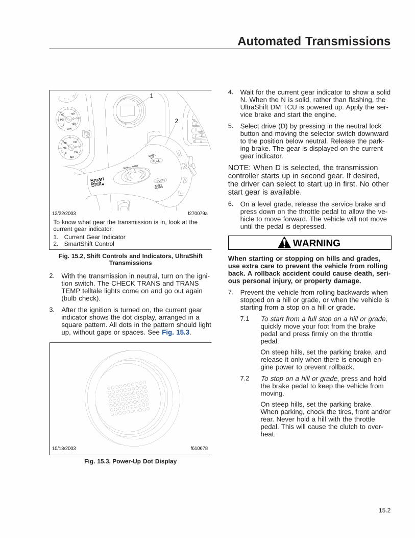
2. With the transmission in neutral, turn on the igni-tion switch. The CHECK TRANS and TRANSTEMP telltale lights come on and go out again(bulb check).
3. After the ignition is turned on, the current gearindicator shows the dot display, arranged in asquare pattern. All dots in the pattern should lightup, without gaps or spaces. See Fig. 15.3 .
4. Wait for the current gear indicator to show a solidN. When the N is solid, rather than flashing, theUltraShift DM TCU is powered up. Apply the ser-vice brake and start the engine.
5. Select drive (D) by pressing in the neutral lockbutton and moving the selector switch downwardto the position below neutral. Release the park-ing brake. The gear is displayed on the currentgear indicator.
NOTE: When D is selected, the transmissioncontroller starts up in second gear. If desired,the driver can select to start up in first. No otherstart gear is available.
6. On a level grade, release the service brake andpress down on the throttle pedal to allow the ve-hicle to move forward. The vehicle will not moveuntil the pedal is depressed.
WARNINGWhen starting or stopping on hills and grades,use extra care to prevent the vehicle from rollingback. A rollback accident could cause death, seri-ous personal injury, or property damage.
7. Prevent the vehicle from rolling backwards whenstopped on a hill or grade, or when the vehicle isstarting from a stop on a hill or grade.
7.1 To start from a full stop on a hill or grade,quickly move your foot from the brakepedal and press firmly on the throttlepedal.
On steep hills, set the parking brake, andrelease it only when there is enough en-gine power to prevent rollback.
7.2 To stop on a hill or grade, press and holdthe brake pedal to keep the vehicle frommoving.
On steep hills, set the parking brake.When parking, chock the tires, front and/orrear. Never hold a hill with the throttlepedal. This will cause the clutch to over-heat.
12/22/2003 f270079a
1
2
To know what gear the transmission is in, look at thecurrent gear indicator.1. Current Gear Indicator2. SmartShift Control
Fig. 15.2, Shift Controls and Indicators, UltraShiftTransmissions
10/13/2003 f610678
Fig. 15.3, Power-Up Dot Display
Automated Transmissions
15.2
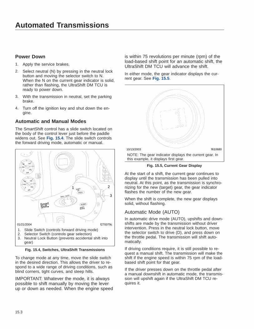
Power Down1. Apply the service brakes.
2. Select neutral (N) by pressing in the neutral lockbutton and moving the selector switch to N.When the N on the current gear indicator is solid,rather than flashing, the UltraShift DM TCU isready to power down.
3. With the transmission in neutral, set the parkingbrake.
4. Turn off the ignition key and shut down the en-gine.
Automatic and Manual ModesThe SmartShift control has a slide switch located onthe body of the control lever just before the paddlewidens out. See Fig. 15.4 . The slide switch controlsthe forward driving mode, automatic or manual.
To change mode at any time, move the slide switchin the desired direction. This allows the driver to re-spond to a wide range of driving conditions, such asblind corners, tight curves, and steep hills.
IMPORTANT: Whatever the mode, it is alwayspossible to shift manually by moving the leverup or down as needed. When the engine speed
is within 75 revolutions per minute (rpm) of theload-based shift point for an automatic shift, theUltraShift DM TCU will advance the shift.
In either mode, the gear indicator displays the cur-rent gear. See Fig. 15.5 .
At the start of a shift, the current gear continues todisplay until the transmission has been pulled intoneutral. At this point, as the transmission is synchro-nizing for the new (target) gear, the gear indicatorflashes the number of the new gear.
When the shift is complete, the new gear displayssolid, without flashing.
Automatic Mode (AUTO)In automatic drive mode (AUTO), upshifts and down-shifts are made by the transmission without driverintervention. Press in the neutral lock button, movethe selector switch to drive (D), and press down onthe throttle pedal. The transmission will shift auto-matically.
If driving conditions require, it is still possible to re-quest a manual shift. The transmission will make theshift if the engine speed is within 75 rpm of the load-based shift point for that gear.
If the driver presses down on the throttle pedal aftera manual downshift in automatic mode, the transmis-sion will upshift again if the UltraShift DM TCU re-quires it.
01/21/2004 f270079c
1 2
3
1. Slide Switch (controls forward driving mode)2. Selector Switch (controls gear selection)3. Neutral Lock Button (prevents accidental shift into
gear)
Fig. 15.4, Switches, UltraShift Transmissions
10/13/2003 f610680
NOTE: The gear indicator displays the current gear. Inthis example, it displays first gear.
Fig. 15.5, Current Gear Display
Automated Transmissions
15.3
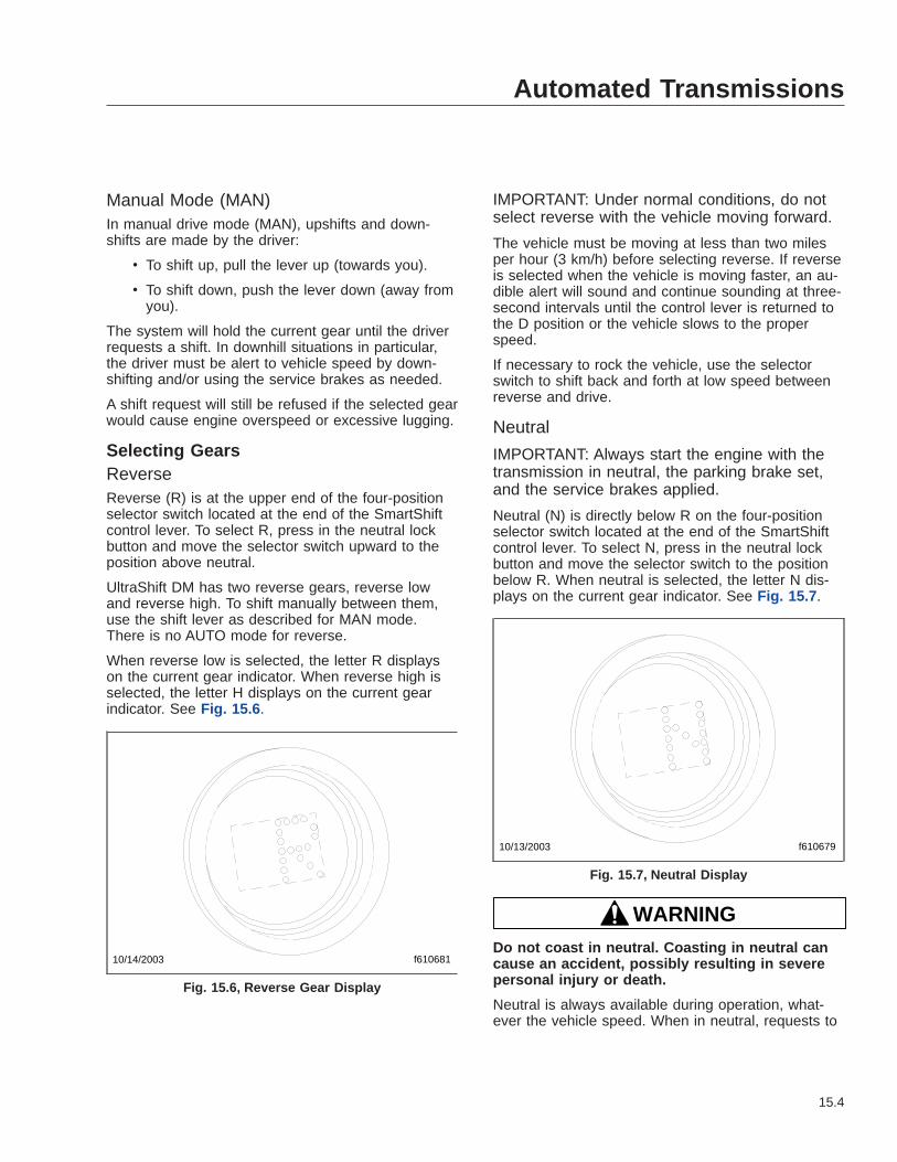
Manual Mode (MAN)In manual drive mode (MAN), upshifts and down-shifts are made by the driver:
• To shift up, pull the lever up (towards you).
• To shift down, push the lever down (away fromyou).
The system will hold the current gear until the driverrequests a shift. In downhill situations in particular,the driver must be alert to vehicle speed by down-shifting and/or using the service brakes as needed.
A shift request will still be refused if the selected gearwould cause engine overspeed or excessive lugging.
Selecting GearsReverseReverse (R) is at the upper end of the four-positionselector switch located at the end of the SmartShiftcontrol lever. To select R, press in the neutral lockbutton and move the selector switch upward to theposition above neutral.
UltraShift DM has two reverse gears, reverse lowand reverse high. To shift manually between them,use the shift lever as described for MAN mode.There is no AUTO mode for reverse.
When reverse low is selected, the letter R displayson the current gear indicator. When reverse high isselected, the letter H displays on the current gearindicator. See Fig. 15.6 .
IMPORTANT: Under normal conditions, do notselect reverse with the vehicle moving forward.
The vehicle must be moving at less than two milesper hour (3 km/h) before selecting reverse. If reverseis selected when the vehicle is moving faster, an au-dible alert will sound and continue sounding at three-second intervals until the control lever is returned tothe D position or the vehicle slows to the properspeed.
If necessary to rock the vehicle, use the selectorswitch to shift back and forth at low speed betweenreverse and drive.
Neutral
IMPORTANT: Always start the engine with thetransmission in neutral, the parking brake set,and the service brakes applied.
Neutral (N) is directly below R on the four-positionselector switch located at the end of the SmartShiftcontrol lever. To select N, press in the neutral lockbutton and move the selector switch to the positionbelow R. When neutral is selected, the letter N dis-plays on the current gear indicator. See Fig. 15.7 .
WARNINGDo not coast in neutral. Coasting in neutral cancause an accident, possibly resulting in severepersonal injury or death.
Neutral is always available during operation, what-ever the vehicle speed. When in neutral, requests to
10/14/2003 f610681
Fig. 15.6, Reverse Gear Display
10/13/2003 f610679
Fig. 15.7, Neutral Display
Automated Transmissions
15.4
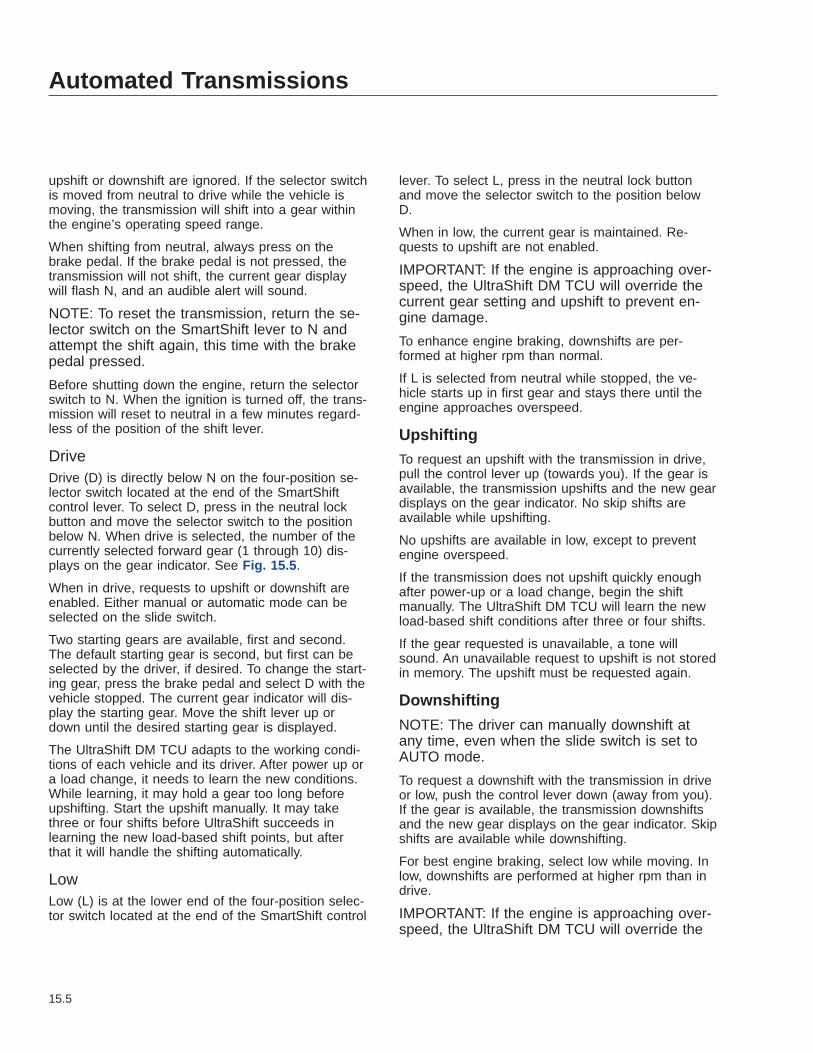
upshift or downshift are ignored. If the selector switchis moved from neutral to drive while the vehicle ismoving, the transmission will shift into a gear withinthe engine’s operating speed range.
When shifting from neutral, always press on thebrake pedal. If the brake pedal is not pressed, thetransmission will not shift, the current gear displaywill flash N, and an audible alert will sound.
NOTE: To reset the transmission, return the se-lector switch on the SmartShift lever to N andattempt the shift again, this time with the brakepedal pressed.
Before shutting down the engine, return the selectorswitch to N. When the ignition is turned off, the trans-mission will reset to neutral in a few minutes regard-less of the position of the shift lever.
DriveDrive (D) is directly below N on the four-position se-lector switch located at the end of the SmartShiftcontrol lever. To select D, press in the neutral lockbutton and move the selector switch to the positionbelow N. When drive is selected, the number of thecurrently selected forward gear (1 through 10) dis-plays on the gear indicator. See Fig. 15.5 .
When in drive, requests to upshift or downshift areenabled. Either manual or automatic mode can beselected on the slide switch.
Two starting gears are available, first and second.The default starting gear is second, but first can beselected by the driver, if desired. To change the start-ing gear, press the brake pedal and select D with thevehicle stopped. The current gear indicator will dis-play the starting gear. Move the shift lever up ordown until the desired starting gear is displayed.
The UltraShift DM TCU adapts to the working condi-tions of each vehicle and its driver. After power up ora load change, it needs to learn the new conditions.While learning, it may hold a gear too long beforeupshifting. Start the upshift manually. It may takethree or four shifts before UltraShift succeeds inlearning the new load-based shift points, but afterthat it will handle the shifting automatically.
LowLow (L) is at the lower end of the four-position selec-tor switch located at the end of the SmartShift control
lever. To select L, press in the neutral lock buttonand move the selector switch to the position belowD.
When in low, the current gear is maintained. Re-quests to upshift are not enabled.
IMPORTANT: If the engine is approaching over-speed, the UltraShift DM TCU will override thecurrent gear setting and upshift to prevent en-gine damage.
To enhance engine braking, downshifts are per-formed at higher rpm than normal.
If L is selected from neutral while stopped, the ve-hicle starts up in first gear and stays there until theengine approaches overspeed.
UpshiftingTo request an upshift with the transmission in drive,pull the control lever up (towards you). If the gear isavailable, the transmission upshifts and the new geardisplays on the gear indicator. No skip shifts areavailable while upshifting.
No upshifts are available in low, except to preventengine overspeed.
If the transmission does not upshift quickly enoughafter power-up or a load change, begin the shiftmanually. The UltraShift DM TCU will learn the newload-based shift conditions after three or four shifts.
If the gear requested is unavailable, a tone willsound. An unavailable request to upshift is not storedin memory. The upshift must be requested again.
Downshifting
NOTE: The driver can manually downshift atany time, even when the slide switch is set toAUTO mode.
To request a downshift with the transmission in driveor low, push the control lever down (away from you).If the gear is available, the transmission downshiftsand the new gear displays on the gear indicator. Skipshifts are available while downshifting.
For best engine braking, select low while moving. Inlow, downshifts are performed at higher rpm than indrive.
IMPORTANT: If the engine is approaching over-speed, the UltraShift DM TCU will override the
Automated Transmissions
15.5
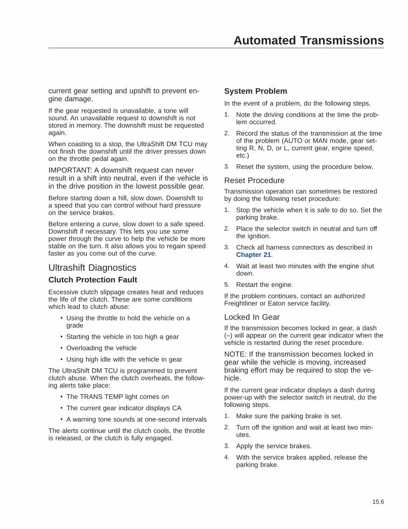
current gear setting and upshift to prevent en-gine damage.
If the gear requested is unavailable, a tone willsound. An unavailable request to downshift is notstored in memory. The downshift must be requestedagain.
When coasting to a stop, the UltraShift DM TCU maynot finish the downshift until the driver presses downon the throttle pedal again.
IMPORTANT: A downshift request can neverresult in a shift into neutral, even if the vehicle isin the drive position in the lowest possible gear.
Before starting down a hill, slow down. Downshift toa speed that you can control without hard pressureon the service brakes.
Before entering a curve, slow down to a safe speed.Downshift if necessary. This lets you use somepower through the curve to help the vehicle be morestable on the turn. It also allows you to regain speedfaster as you come out of the curve.
Ultrashift DiagnosticsClutch Protection FaultExcessive clutch slippage creates heat and reducesthe life of the clutch. These are some conditionswhich lead to clutch abuse:
• Using the throttle to hold the vehicle on agrade
• Starting the vehicle in too high a gear
• Overloading the vehicle
• Using high idle with the vehicle in gear
The UltraShift DM TCU is programmed to preventclutch abuse. When the clutch overheats, the follow-ing alerts take place:
• The TRANS TEMP light comes on
• The current gear indicator displays CA
• A warning tone sounds at one-second intervals
The alerts continue until the clutch cools, the throttleis released, or the clutch is fully engaged.
System ProblemIn the event of a problem, do the following steps.
1. Note the driving conditions at the time the prob-lem occurred.
2. Record the status of the transmission at the timeof the problem (AUTO or MAN mode, gear set-ting R, N, D, or L, current gear, engine speed,etc.)
3. Reset the system, using the procedure below.
Reset ProcedureTransmission operation can sometimes be restoredby doing the following reset procedure:
1. Stop the vehicle when it is safe to do so. Set theparking brake.
2. Place the selector switch in neutral and turn offthe ignition.
3. Check all harness connectors as described inChapter 21 .
4. Wait at least two minutes with the engine shutdown.
5. Restart the engine.
If the problem continues, contact an authorizedFreightliner or Eaton service facility.
Locked In GearIf the transmission becomes locked in gear, a dash(–) will appear on the current gear indicator when thevehicle is restarted during the reset procedure.
NOTE: If the transmission becomes locked ingear while the vehicle is moving, increasedbraking effort may be required to stop the ve-hicle.
If the current gear indicator displays a dash duringpower-up with the selector switch in neutral, do thefollowing steps.
1. Make sure the parking brake is set.
2. Turn off the ignition and wait at least two min-utes.
3. Apply the service brakes.
4. With the service brakes applied, release theparking brake.
Automated Transmissions
15.6
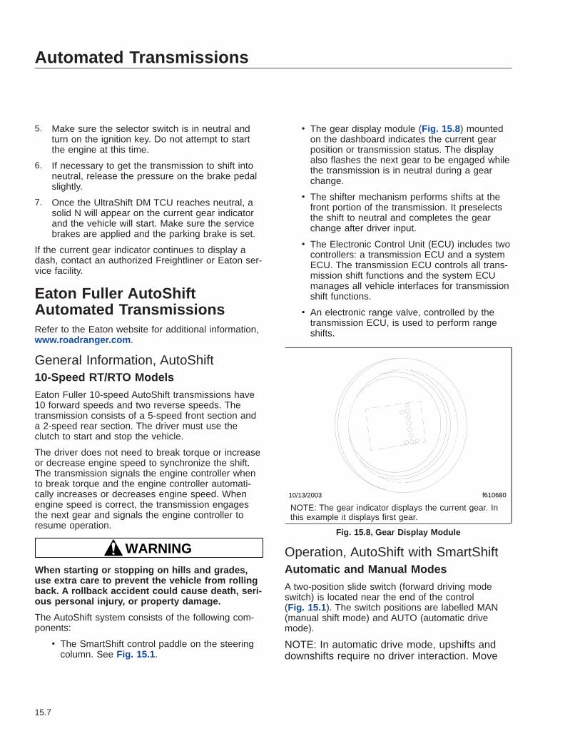
5. Make sure the selector switch is in neutral andturn on the ignition key. Do not attempt to startthe engine at this time.
6. If necessary to get the transmission to shift intoneutral, release the pressure on the brake pedalslightly.
7. Once the UltraShift DM TCU reaches neutral, asolid N will appear on the current gear indicatorand the vehicle will start. Make sure the servicebrakes are applied and the parking brake is set.
If the current gear indicator continues to display adash, contact an authorized Freightliner or Eaton ser-vice facility.
Eaton Fuller AutoShiftAutomated TransmissionsRefer to the Eaton website for additional information,www.roadranger.com .
General Information, AutoShift10-Speed RT/RTO ModelsEaton Fuller 10-speed AutoShift transmissions have10 forward speeds and two reverse speeds. Thetransmission consists of a 5-speed front section anda 2-speed rear section. The driver must use theclutch to start and stop the vehicle.
The driver does not need to break torque or increaseor decrease engine speed to synchronize the shift.The transmission signals the engine controller whento break torque and the engine controller automati-cally increases or decreases engine speed. Whenengine speed is correct, the transmission engagesthe next gear and signals the engine controller toresume operation.
WARNINGWhen starting or stopping on hills and grades,use extra care to prevent the vehicle from rollingback. A rollback accident could cause death, seri-ous personal injury, or property damage.
The AutoShift system consists of the following com-ponents:
• The SmartShift control paddle on the steeringcolumn. See Fig. 15.1 .
• The gear display module (Fig. 15.8 ) mountedon the dashboard indicates the current gearposition or transmission status. The displayalso flashes the next gear to be engaged whilethe transmission is in neutral during a gearchange.
• The shifter mechanism performs shifts at thefront portion of the transmission. It preselectsthe shift to neutral and completes the gearchange after driver input.
• The Electronic Control Unit (ECU) includes twocontrollers: a transmission ECU and a systemECU. The transmission ECU controls all trans-mission shift functions and the system ECUmanages all vehicle interfaces for transmissionshift functions.
• An electronic range valve, controlled by thetransmission ECU, is used to perform rangeshifts.
Operation, AutoShift with SmartShiftAutomatic and Manual ModesA two-position slide switch (forward driving modeswitch) is located near the end of the control(Fig. 15.1 ). The switch positions are labelled MAN(manual shift mode) and AUTO (automatic drivemode).
NOTE: In automatic drive mode, upshifts anddownshifts require no driver interaction. Move
10/13/2003 f610680
NOTE: The gear indicator displays the current gear. Inthis example it displays first gear.
Fig. 15.8, Gear Display Module
Automated Transmissions
15.7
the selector switch to the drive (D) position, dis-engage the clutch to engage the gear selected,engage the clutch and drive the vehicle. Inmanual shift mode, upshifts and downshifts re-quire either a pull upward or push downward onthe control.
Driver Message CenterGear information is presented to the driver on thedash display. In automatic drive mode, the number ofthe forward gear currently engaged appears continu-ally on the message display screen when in drive(D). In manual shift mode, the current gear is dis-played until a new gear is requested. When neutral(N) is engaged, "N" will appear on the message dis-play screen. When reverse (R) is engaged, either"RL" or "RH" will appear on the message displayscreen.
IMPORTANT: The information shown on themessage display screen indicates the state ofthe transmission only, not the state of theSmartShift control.
Neutral PositionSelect neutral by sliding the selector switch to the"N" position.
NOTE: Neutral is always available during opera-tion. When in neutral, upshift and downshift re-quests are ignored. If the mode selector switchis moved from neutral (N) to drive (D) while thevehicle is moving, the transmission will shift intoa gear causing the engine to go to a high torquelevel, under the engine’s rated torque.
WARNINGDo not coast in neutral. Coasting in neutral cancause an accident, possibly resulting in severepersonal injury or death.
Selecting a Starting Gear1. In automatic mode, select drive (D) by sliding the
selector switch downward to the next positionbelow the neutral position.
2. Disengage the clutch to engage the gear se-lected. Engage the clutch and drive the vehicle.
Changing the Default Starting GearTo select a starting gear other than the default start-ing gear, follow the instructions below.
1. Make sure the vehicle is stopped and in drive.
2. In either automatic or manual mode, pull upwardon the control (to increase), or push downward(to decrease). Each pull upward on the controlincreases the starting gear by one gear, but nohigher than fourth gear.
3. The number of the gear selected will flash on themessage display screen until the driver engagesthe clutch. This gear will be stored in memory asthe default starting gear until either a differentstarting gear is selected by the driver or the en-gine is shut down.
NOTE: The transmission may also be pro-grammed so that it is not possible to select astarting gear other than the preprogrammed de-fault starting gear.
Upshifting
NOTE: With the transmission in drive (D) in theautomatic mode, upshifts require no driver inter-action.
1. With the transmission in drive in the manualmode, request an upshift by pulling upward onthe control. If the requested gear is available, thetransmission will upshift.
NOTE: A single, momentary pull upward on thecontrol selects the next higher gear when it isavailable. Two consecutive, momentary upwardpulls will cause a skip shift when the next twohigher gears are available and conditions areright.
2. To skip shift, move the control two times in lessthan 1/2 second. The number of the gear en-gaged will appear on the message displayscreen.
NOTE: The Eaton Fuller AutoShift 18-speedtransmission is able to perform triple upshiftswhen the next three higher gears are availableand conditions are right. To triple-shift this trans-mission, move the control three times in lessthan 1/2 second.
Automated Transmissions
15.8
If a requested gear is not available, an audiblewarning will sound and the gear display modulewill indicate that the gear is not available. Anunavailable requested upshift is not stored inmemory. The upshift must be requested again.
Downshifting
NOTE: With the transmission in drive (D) in theautomatic mode, downshifts require no driverinteraction.
1. With the transmission in drive in the manualmode, request a downshift by pushing downwardon the control. If the requested gear is available,the transmission will downshift.
NOTE: A single, momentary push downward onthe control selects the next lower gear when it isavailable. Two consecutive, momentary down-ward pushes will cause a skip shift, when thenext two lower gears are available and condi-tions are right.
2. To skip shift, move the control two times in lessthan 1/2 second. The number of the gear en-gaged will appear on the message displayscreen.
NOTE: The Eaton Fuller AutoShift 18-speedtransmission is able to perform triple downshiftswhen the next three lower gears are availableand conditions are right. To triple shift this trans-mission, move the control three times in lessthan 1/2 second.
If a requested gear is not available, an audiblewarning will sound and the gear display modulewill indicate that the requested gear is not avail-able. Unlike upshifting, an unavailable requesteddownshift is stored in memory and the shift willbe made when the gear is available. The timelimit for this memory is a programmable param-eter.
Start-Up1. With the parking brake applied, press the clutch
all the way down to the floor.
2. Start the engine.
3. Check to make sure the transmission is in neu-tral.
4. With the transmission in neutral, release theclutch.
NOTE: This allows the speed sensor on theinput shaft to get a reading.
5. Press down on the clutch again and release theparking brake.
6. Select the desired starting gear.
7. Release the clutch.
Reverse1. To engage reverse (R), slide the selector switch
upward to the next position above the neutralposition and disengage the clutch.
NOTE: AutoShift 10- and 18-speed transmis-sions have a dual-range reverse. Reverse low(RL) is the default reverse gear.
2. Select reverse high (RH) by pulling upward onthe control.
NOTE: Reverse may be engaged below a pro-grammable forward speed in order to rock thevehicle. If reverse is selected above the pro-grammed forward speed, an audible warning willsound and a message indicating that the gear isnot available will appear on the message dis-play screen.
Low Gear OperationUse low (L) when descending steep hills and usingcompression braking. Engine speed will be increasedby 200 rpm and shift points will be offset by 200 rpm.The efficiency of the exhaust brake will be maxi-mized.
Using the ClutchUse the clutch to start and stop the vehicle.
Automated Transmissions
15.9
16
Drive AxlesDrive Axles with Differential Lock . . . . . . . . . . . . . . . . . . . . . . . . . . . . . . . . . . . . . . . . . . . . . . . . . . . . 16.1Two-Speed Drive Axles . . . . . . . . . . . . . . . . . . . . . . . . . . . . . . . . . . . . . . . . . . . . . . . . . . . . . . . . . . . 16.2
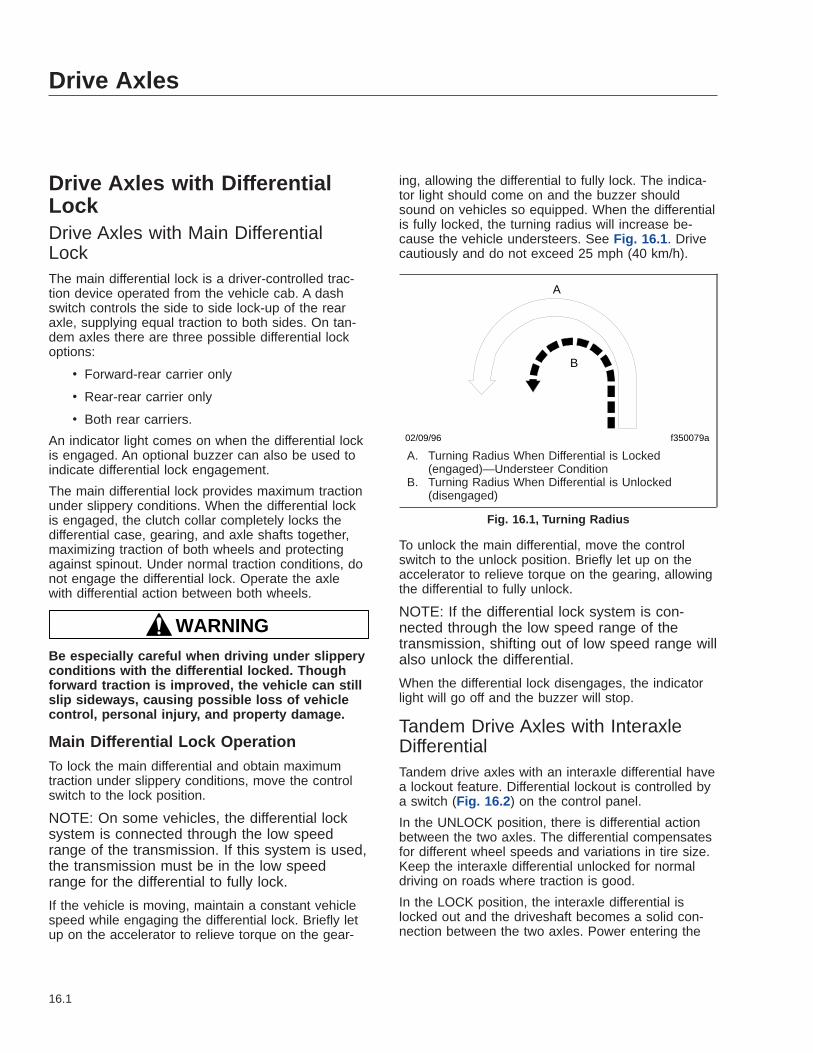
Drive Axles with DifferentialLockDrive Axles with Main DifferentialLockThe main differential lock is a driver-controlled trac-tion device operated from the vehicle cab. A dashswitch controls the side to side lock-up of the rearaxle, supplying equal traction to both sides. On tan-dem axles there are three possible differential lockoptions:
• Forward-rear carrier only
• Rear-rear carrier only
• Both rear carriers.
An indicator light comes on when the differential lockis engaged. An optional buzzer can also be used toindicate differential lock engagement.
The main differential lock provides maximum tractionunder slippery conditions. When the differential lockis engaged, the clutch collar completely locks thedifferential case, gearing, and axle shafts together,maximizing traction of both wheels and protectingagainst spinout. Under normal traction conditions, donot engage the differential lock. Operate the axlewith differential action between both wheels.
WARNINGBe especially careful when driving under slipperyconditions with the differential locked. Thoughforward traction is improved, the vehicle can stillslip sideways, causing possible loss of vehiclecontrol, personal injury, and property damage.
Main Differential Lock OperationTo lock the main differential and obtain maximumtraction under slippery conditions, move the controlswitch to the lock position.
NOTE: On some vehicles, the differential locksystem is connected through the low speedrange of the transmission. If this system is used,the transmission must be in the low speedrange for the differential to fully lock.
If the vehicle is moving, maintain a constant vehiclespeed while engaging the differential lock. Briefly letup on the accelerator to relieve torque on the gear-
ing, allowing the differential to fully lock. The indica-tor light should come on and the buzzer shouldsound on vehicles so equipped. When the differentialis fully locked, the turning radius will increase be-cause the vehicle understeers. See Fig. 16.1 . Drivecautiously and do not exceed 25 mph (40 km/h).
To unlock the main differential, move the controlswitch to the unlock position. Briefly let up on theaccelerator to relieve torque on the gearing, allowingthe differential to fully unlock.
NOTE: If the differential lock system is con-nected through the low speed range of thetransmission, shifting out of low speed range willalso unlock the differential.
When the differential lock disengages, the indicatorlight will go off and the buzzer will stop.
Tandem Drive Axles with InteraxleDifferentialTandem drive axles with an interaxle differential havea lockout feature. Differential lockout is controlled bya switch (Fig. 16.2 ) on the control panel.
In the UNLOCK position, there is differential actionbetween the two axles. The differential compensatesfor different wheel speeds and variations in tire size.Keep the interaxle differential unlocked for normaldriving on roads where traction is good.
In the LOCK position, the interaxle differential islocked out and the driveshaft becomes a solid con-nection between the two axles. Power entering the
02/09/96 f350079a
A
B
A. Turning Radius When Differential is Locked(engaged)—Understeer Condition
B. Turning Radius When Differential is Unlocked(disengaged)
Fig. 16.1, Turning Radius
Drive Axles
16.1
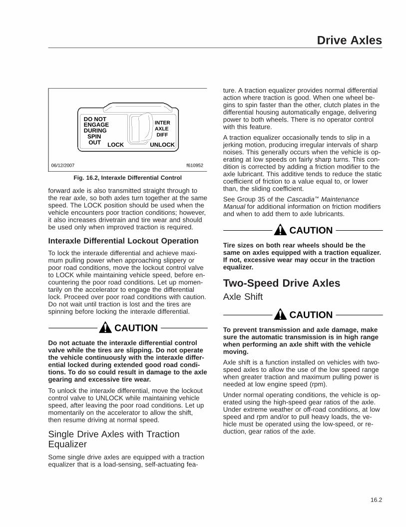
forward axle is also transmitted straight through tothe rear axle, so both axles turn together at the samespeed. The LOCK position should be used when thevehicle encounters poor traction conditions; however,it also increases drivetrain and tire wear and shouldbe used only when improved traction is required.
Interaxle Differential Lockout OperationTo lock the interaxle differential and achieve maxi-mum pulling power when approaching slippery orpoor road conditions, move the lockout control valveto LOCK while maintaining vehicle speed, before en-countering the poor road conditions. Let up momen-tarily on the accelerator to engage the differentiallock. Proceed over poor road conditions with caution.Do not wait until traction is lost and the tires arespinning before locking the interaxle differential.
CAUTIONDo not actuate the interaxle differential controlvalve while the tires are slipping. Do not operatethe vehicle continuously with the interaxle differ-ential locked during extended good road condi-tions. To do so could result in damage to the axlegearing and excessive tire wear.
To unlock the interaxle differential, move the lockoutcontrol valve to UNLOCK while maintaining vehiclespeed, after leaving the poor road conditions. Let upmomentarily on the accelerator to allow the shift,then resume driving at normal speed.
Single Drive Axles with TractionEqualizerSome single drive axles are equipped with a tractionequalizer that is a load-sensing, self-actuating fea-
ture. A traction equalizer provides normal differentialaction where traction is good. When one wheel be-gins to spin faster than the other, clutch plates in thedifferential housing automatically engage, deliveringpower to both wheels. There is no operator controlwith this feature.
A traction equalizer occasionally tends to slip in ajerking motion, producing irregular intervals of sharpnoises. This generally occurs when the vehicle is op-erating at low speeds on fairly sharp turns. This con-dition is corrected by adding a friction modifier to theaxle lubricant. This additive tends to reduce the staticcoefficient of friction to a value equal to, or lowerthan, the sliding coefficient.
See Group 35 of the Cascadia™ MaintenanceManual for additional information on friction modifiersand when to add them to axle lubricants.
CAUTIONTire sizes on both rear wheels should be thesame on axles equipped with a traction equalizer.If not, excessive wear may occur in the tractionequalizer.
Two-Speed Drive AxlesAxle Shift
CAUTIONTo prevent transmission and axle damage, makesure the automatic transmission is in high rangewhen performing an axle shift with the vehiclemoving.
Axle shift is a function installed on vehicles with two-speed axles to allow the use of the low speed rangewhen greater traction and maximum pulling power isneeded at low engine speed (rpm).
Under normal operating conditions, the vehicle is op-erated using the high-speed gear ratios of the axle.Under extreme weather or off-road conditions, at lowspeed and rpm and/or to pull heavy loads, the ve-hicle must be operated using the low-speed, or re-duction, gear ratios of the axle.
DO NOTENGAGEDURING
SPINOUT LOCK UNLOCK
INTERAXLEDIFF
06/12/2007 f610952
Fig. 16.2, Interaxle Differential Control
Drive Axles
16.2
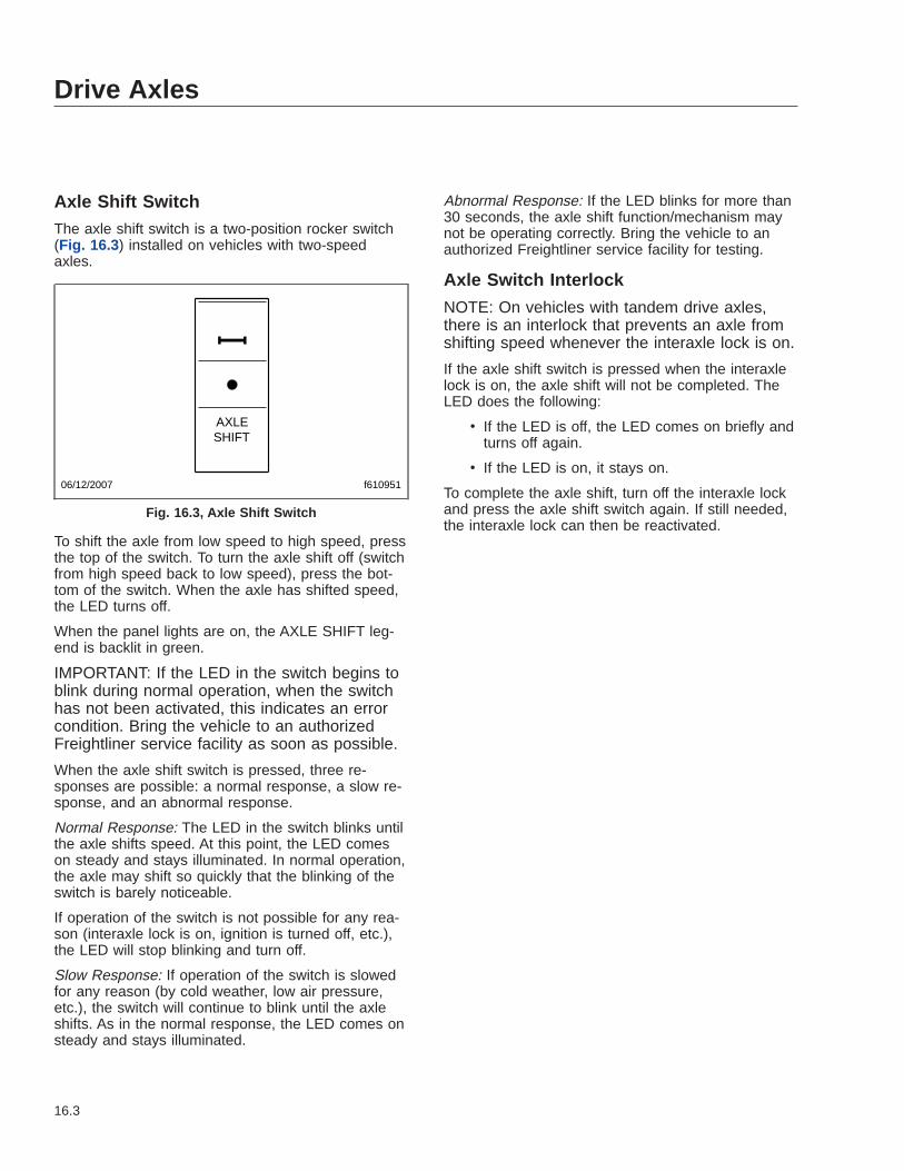
Axle Shift SwitchThe axle shift switch is a two-position rocker switch(Fig. 16.3 ) installed on vehicles with two-speedaxles.
To shift the axle from low speed to high speed, pressthe top of the switch. To turn the axle shift off (switchfrom high speed back to low speed), press the bot-tom of the switch. When the axle has shifted speed,the LED turns off.
When the panel lights are on, the AXLE SHIFT leg-end is backlit in green.
IMPORTANT: If the LED in the switch begins toblink during normal operation, when the switchhas not been activated, this indicates an errorcondition. Bring the vehicle to an authorizedFreightliner service facility as soon as possible.
When the axle shift switch is pressed, three re-sponses are possible: a normal response, a slow re-sponse, and an abnormal response.
Normal Response: The LED in the switch blinks untilthe axle shifts speed. At this point, the LED comeson steady and stays illuminated. In normal operation,the axle may shift so quickly that the blinking of theswitch is barely noticeable.
If operation of the switch is not possible for any rea-son (interaxle lock is on, ignition is turned off, etc.),the LED will stop blinking and turn off.
Slow Response: If operation of the switch is slowedfor any reason (by cold weather, low air pressure,etc.), the switch will continue to blink until the axleshifts. As in the normal response, the LED comes onsteady and stays illuminated.
Abnormal Response: If the LED blinks for more than30 seconds, the axle shift function/mechanism maynot be operating correctly. Bring the vehicle to anauthorized Freightliner service facility for testing.
Axle Switch Interlock
NOTE: On vehicles with tandem drive axles,there is an interlock that prevents an axle fromshifting speed whenever the interaxle lock is on.
If the axle shift switch is pressed when the interaxlelock is on, the axle shift will not be completed. TheLED does the following:
• If the LED is off, the LED comes on briefly andturns off again.
• If the LED is on, it stays on.
To complete the axle shift, turn off the interaxle lockand press the axle shift switch again. If still needed,the interaxle lock can then be reactivated.
AXLESHIFT
f61095106/12/2007
Fig. 16.3, Axle Shift Switch
Drive Axles
16.3
17
Steering SystemPower Steering System General Information . . . . . . . . . . . . . . . . . . . . . . . . . . . . . . . . . . . . . . . . . . 17.1Power Steering Systems . . . . . . . . . . . . . . . . . . . . . . . . . . . . . . . . . . . . . . . . . . . . . . . . . . . . . . . . . . 17.1
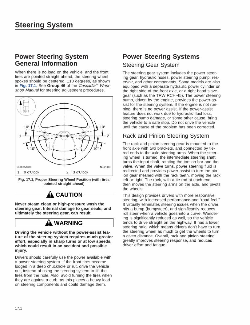
Power Steering SystemGeneral InformationWhen there is no load on the vehicle, and the fronttires are pointed straight ahead, the steering wheelspokes should be centered, ±10 degrees, as shownin Fig. 17.1 . See Group 46 of the Cascadia™ Work-shop Manual for steering adjustment procedures.
CAUTIONNever steam clean or high-pressure wash thesteering gear. Internal damage to gear seals, andultimately the steering gear, can result.
WARNINGDriving the vehicle without the power-assist fea-ture of the steering system requires much greatereffort, especially in sharp turns or at low speeds,which could result in an accident and possibleinjury.
Drivers should carefully use the power available witha power steering system. If the front tires becomelodged in a deep chuckhole or rut, drive the vehicleout, instead of using the steering system to lift thetires from the hole. Also, avoid turning the tires whenthey are against a curb, as this places a heavy loadon steering components and could damage them.
Power Steering SystemsSteering Gear SystemThe steering gear system includes the power steer-ing gear, hydraulic hoses, power steering pump, res-ervoir, and other components. Some models are alsoequipped with a separate hydraulic power cylinder onthe right side of the front axle, or a right-hand slavegear (such as the TRW RCH-45). The power steeringpump, driven by the engine, provides the power as-sist for the steering system. If the engine is not run-ning, there is no power assist. If the power-assistfeature does not work due to hydraulic fluid loss,steering pump damage, or some other cause, bringthe vehicle to a safe stop. Do not drive the vehicleuntil the cause of the problem has been corrected.
Rack and Pinion Steering SystemThe rack and pinion steering gear is mounted to thefront axle with two brackets, and connected by tie-rod ends to the axle steering arms. When the steer-ing wheel is turned, the intermediate steering shaftturns the input shaft, rotating the torsion bar and thevalve. When the valve turns, power steering fluid isredirected and provides power assist to turn the pin-ion gear meshed with the rack teeth, moving the rackleft or right. The rack, with a tie-rod at each end,then moves the steering arms on the axle, and pivotsthe wheels.
This design provides drivers with more responsivesteering, with increased performance and “road feel.”It virtually eliminates steering issues when the driverhits a bump (bumpsteer), and significantly reducesroll steer when a vehicle goes into a curve. Wander-ing is significantly reduced as well, so the vehicletends to drive straight on the highway. It has a lowersteering ratio, which means drivers don’t have to turnthe steering wheel as much to get the wheels to turna given distance. Overall, rack and pinion steeringgreatly improves steering response, and reducesdriver effort and fatigue.
06/13/2007 f462080
10°
10°
1 2
10°
10°
1. 9 o’Clock 2. 3 o’Clock
Fig. 17.1, Proper Steering Wheel Position (with tirespointed straight ahead)
Steering System
17.1
18
Fifth WheelsFifth Wheels, General Information . . . . . . . . . . . . . . . . . . . . . . . . . . . . . . . . . . . . . . . . . . . . . . . . . . . 18.1Fifth Wheel Coupling . . . . . . . . . . . . . . . . . . . . . . . . . . . . . . . . . . . . . . . . . . . . . . . . . . . . . . . . . . . . . 18.1Fifth Wheel Uncoupling . . . . . . . . . . . . . . . . . . . . . . . . . . . . . . . . . . . . . . . . . . . . . . . . . . . . . . . . . . . 18.4Fifth Wheel Slide . . . . . . . . . . . . . . . . . . . . . . . . . . . . . . . . . . . . . . . . . . . . . . . . . . . . . . . . . . . . . . . . 18.7
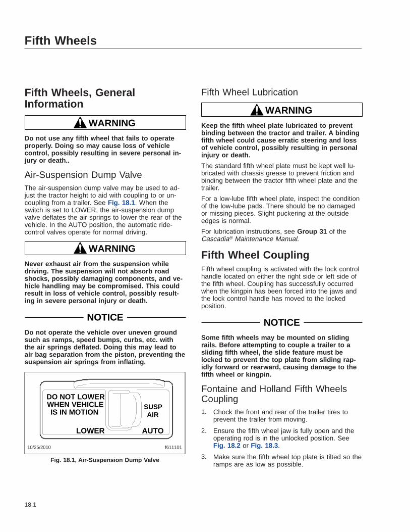
Fifth Wheels, GeneralInformation
WARNINGDo not use any fifth wheel that fails to operateproperly. Doing so may cause loss of vehiclecontrol, possibly resulting in severe personal in-jury or death..
Air-Suspension Dump ValveThe air-suspension dump valve may be used to ad-just the tractor height to aid with coupling to or un-coupling from a trailer. See Fig. 18.1 . When theswitch is set to LOWER, the air-suspension dumpvalve deflates the air springs to lower the rear of thevehicle. In the AUTO position, the automatic ride-control valves operate for normal driving.
WARNINGNever exhaust air from the suspension whiledriving. The suspension will not absorb roadshocks, possibly damaging components, and ve-hicle handling may be compromised. This couldresult in loss of vehicle control, possibly result-ing in severe personal injury or death.
NOTICEDo not operate the vehicle over uneven groundsuch as ramps, speed bumps, curbs, etc. withthe air springs deflated. Doing this may lead toair bag separation from the piston, preventing thesuspension air springs from inflating.
Fifth Wheel Lubrication
WARNINGKeep the fifth wheel plate lubricated to preventbinding between the tractor and trailer. A bindingfifth wheel could cause erratic steering and lossof vehicle control, possibly resulting in personalinjury or death.
The standard fifth wheel plate must be kept well lu-bricated with chassis grease to prevent friction andbinding between the tractor fifth wheel plate and thetrailer.
For a low-lube fifth wheel plate, inspect the conditionof the low-lube pads. There should be no damagedor missing pieces. Slight puckering at the outsideedges is normal.
For lubrication instructions, see Group 31 of theCascadia® Maintenance Manual.
Fifth Wheel CouplingFifth wheel coupling is activated with the lock controlhandle located on either the right side or left side ofthe fifth wheel. Coupling has successfully occurredwhen the kingpin has been forced into the jaws andthe lock control handle has moved to the lockedposition.
NOTICESome fifth wheels may be mounted on slidingrails. Before attempting to couple a trailer to asliding fifth wheel, the slide feature must belocked to prevent the top plate from sliding rap-idly forward or rearward, causing damage to thefifth wheel or kingpin.
Fontaine and Holland Fifth WheelsCoupling1. Chock the front and rear of the trailer tires to
prevent the trailer from moving.
2. Ensure the fifth wheel jaw is fully open and theoperating rod is in the unlocked position. SeeFig. 18.2 or Fig. 18.3 .
3. Make sure the fifth wheel top plate is tilted so theramps are as low as possible.
10/25/2010 f611101
DO NOT LOWERWHEN VEHICLEIS IN MOTION
LOWER AUTO
SUSPAIR
Fig. 18.1, Air-Suspension Dump Valve
Fifth Wheels
18.1
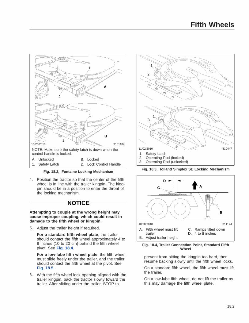
4. Position the tractor so that the center of the fifthwheel is in line with the trailer kingpin. The king-pin should be in a position to enter the throat ofthe locking mechanism.
NOTICEAttempting to couple at the wrong height maycause improper coupling, which could result indamage to the fifth wheel or kingpin.
5. Adjust the trailer height if required.
For a standard fifth wheel plate , the trailershould contact the fifth wheel approximately 4 to8 inches (10 to 20 cm) behind the fifth wheelpivot. See Fig. 18.4 .
For a low-lube fifth wheel plate , the fifth wheelmust slide freely under the trailer, and the trailershould contact the fifth wheel at the pivot. SeeFig. 18.5 .
6. With the fifth wheel lock opening aligned with thetrailer kingpin, back the tractor slowly toward thetrailer. After sliding under the trailer, STOP to
prevent from hitting the kingpin too hard, thenresume backing slowly until the fifth wheel locks.
On a standard fifth wheel, the fifth wheel must liftthe trailer.
On a low-lube fifth wheel, do not lift the trailer asthis may damage the fifth wheel plate.
1
1
2
2 10/26/2010 f310110a
A
B
NOTE: Make sure the safety latch is down when thecontrol handle is locked.
A. Unlocked B. Locked1. Safety Latch 2. Lock Control Handle
Fig. 18.2, Fontaine Locking Mechanism
1
1
2
3
11/02/2010 f310447
1. Safety Latch2. Operating Rod (locked)3. Operating Rod (unlocked)
Fig. 18.3, Holland Simplex SE Locking Mechanism
10/28/2010 f311124
A
B
C
D
A. Fifth wheel must lifttrailer
B. Adjust trailer height
C. Ramps tilted downD. 4 to 8 inches
Fig. 18.4, Trailer Connection Point, Standard FifthWheel
Fifth Wheels
18.2
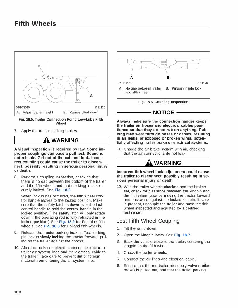
7. Apply the tractor parking brakes.
WARNINGA visual inspection is required by law. Some im-proper couplings can pass a pull test. Sound isnot reliable. Get out of the cab and look. Incor-rect coupling could cause the trailer to discon-nect, possibly resulting in serious personal injuryor death.
8. Perform a coupling inspection, checking thatthere is no gap between the bottom of the trailerand the fifth wheel, and that the kingpin is se-curely locked. See Fig. 18.6
When lockup has occurred, the fifth wheel con-trol handle moves to the locked position. Makesure that the safety latch is down over the lockcontrol handle to hold the control handle in thelocked position. (The safety latch will only rotatedown if the operating rod is fully retracted in thelocked position.) See Fig. 18.2 for Fontaine fifthwheels. See Fig. 18.3 for Holland fifth wheels.
9. Release the tractor parking brakes. Test for king-pin lockup slowly inching the tractor forward, pull-ing on the trailer against the chocks.
10. After lockup is completed, connect the tractor-to-trailer air system lines and the electrical cable tothe trailer. Take care to prevent dirt or foreignmaterial from entering the air system lines.
NOTICEAlways make sure the connection hanger keepsthe trailer air hoses and electrical cables posi-tioned so that they do not rub on anything. Rub-bing may wear through hoses or cables, resultingin air leaks, or exposed or broken wires, poten-tially affecting trailer brake or electrical systems.
11. Charge the air brake system with air, checkingthat the air connections do not leak.
WARNINGIncorrect fifth wheel lock adjustment could causethe trailer to disconnect, possibly resulting in se-rious personal injury or death.
12. With the trailer wheels chocked and the brakesset, check for clearance between the kingpin andthe fifth wheel jaws by moving the tractor forwardand backward against the locked kingpin. If slackis present, uncouple the trailer and have the fifthwheel inspected and adjusted by a certifiedtechnician.
Jost Fifth Wheel Coupling1. Tilt the ramp down.
2. Open the kingpin locks. See Fig. 18.7 .
3. Back the vehicle close to the trailer, centering thekingpin on the fifth wheel.
4. Chock the trailer wheels.
5. Connect the air lines and electrical cable.
6. Ensure that the red trailer air supply valve (trailerbrake) is pulled out, and that the trailer parking
09/10/2010 f311125
A
B
A. Adjust trailer height B. Ramps tilted down
Fig. 18.5, Trailer Connection Point, Low-Lube FifthWheel
09/10/2010 f311126
A B
A. No gap between trailerand fifth wheel
B. Kingpin inside lock
Fig. 18.6, Coupling Inspection
Fifth Wheels
18.3
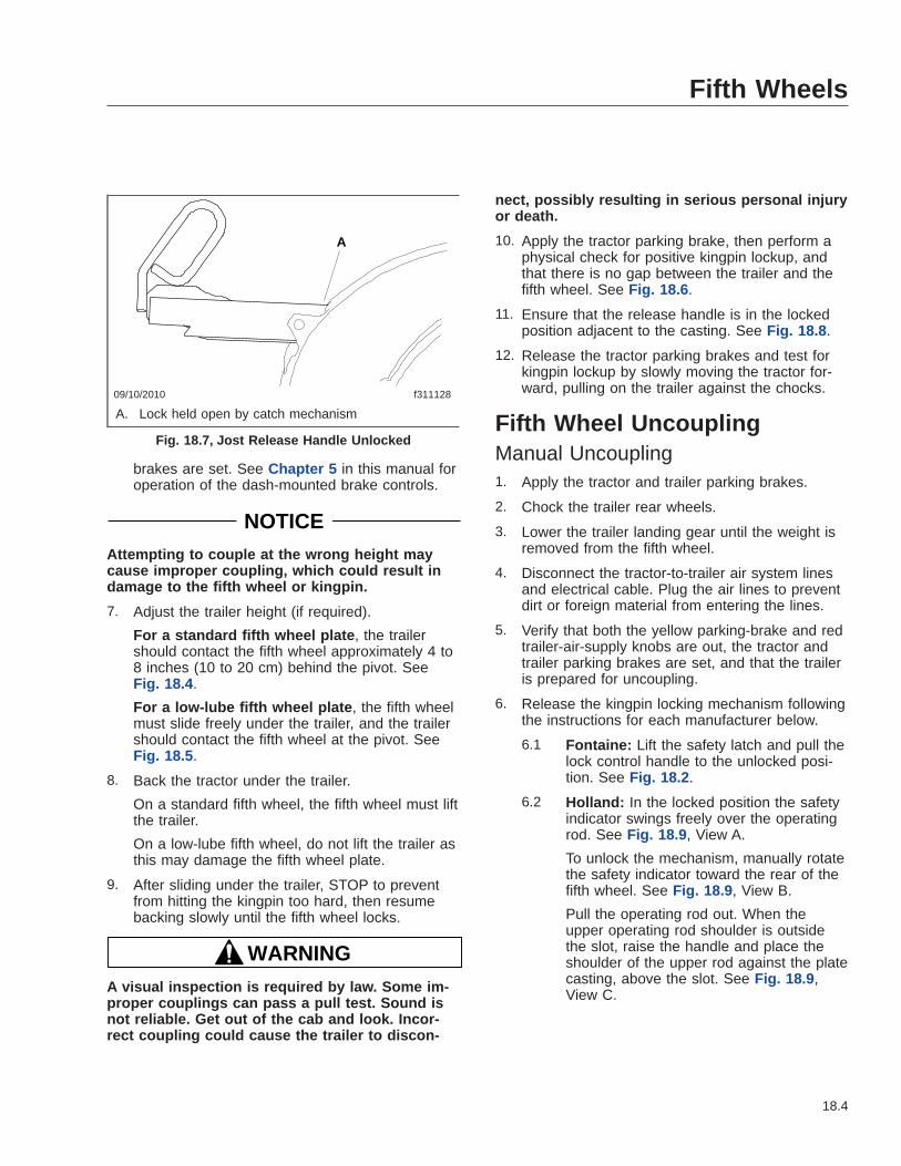
brakes are set. See Chapter 5 in this manual foroperation of the dash-mounted brake controls.
NOTICEAttempting to couple at the wrong height maycause improper coupling, which could result indamage to the fifth wheel or kingpin.
7. Adjust the trailer height (if required).
For a standard fifth wheel plate , the trailershould contact the fifth wheel approximately 4 to8 inches (10 to 20 cm) behind the pivot. SeeFig. 18.4 .
For a low-lube fifth wheel plate , the fifth wheelmust slide freely under the trailer, and the trailershould contact the fifth wheel at the pivot. SeeFig. 18.5 .
8. Back the tractor under the trailer.
On a standard fifth wheel, the fifth wheel must liftthe trailer.
On a low-lube fifth wheel, do not lift the trailer asthis may damage the fifth wheel plate.
9. After sliding under the trailer, STOP to preventfrom hitting the kingpin too hard, then resumebacking slowly until the fifth wheel locks.
WARNINGA visual inspection is required by law. Some im-proper couplings can pass a pull test. Sound isnot reliable. Get out of the cab and look. Incor-rect coupling could cause the trailer to discon-
nect, possibly resulting in serious personal injuryor death.
10. Apply the tractor parking brake, then perform aphysical check for positive kingpin lockup, andthat there is no gap between the trailer and thefifth wheel. See Fig. 18.6 .
11. Ensure that the release handle is in the lockedposition adjacent to the casting. See Fig. 18.8 .
12. Release the tractor parking brakes and test forkingpin lockup by slowly moving the tractor for-ward, pulling on the trailer against the chocks.
Fifth Wheel UncouplingManual Uncoupling1. Apply the tractor and trailer parking brakes.
2. Chock the trailer rear wheels.
3. Lower the trailer landing gear until the weight isremoved from the fifth wheel.
4. Disconnect the tractor-to-trailer air system linesand electrical cable. Plug the air lines to preventdirt or foreign material from entering the lines.
5. Verify that both the yellow parking-brake and redtrailer-air-supply knobs are out, the tractor andtrailer parking brakes are set, and that the traileris prepared for uncoupling.
6. Release the kingpin locking mechanism followingthe instructions for each manufacturer below.
6.1 Fontaine: Lift the safety latch and pull thelock control handle to the unlocked posi-tion. See Fig. 18.2 .
6.2 Holland: In the locked position the safetyindicator swings freely over the operatingrod. See Fig. 18.9 , View A.
To unlock the mechanism, manually rotatethe safety indicator toward the rear of thefifth wheel. See Fig. 18.9 , View B.
Pull the operating rod out. When theupper operating rod shoulder is outsidethe slot, raise the handle and place theshoulder of the upper rod against the platecasting, above the slot. See Fig. 18.9 ,View C.
09/10/2010 f311128
A
A. Lock held open by catch mechanism
Fig. 18.7, Jost Release Handle Unlocked
Fifth Wheels
18.4
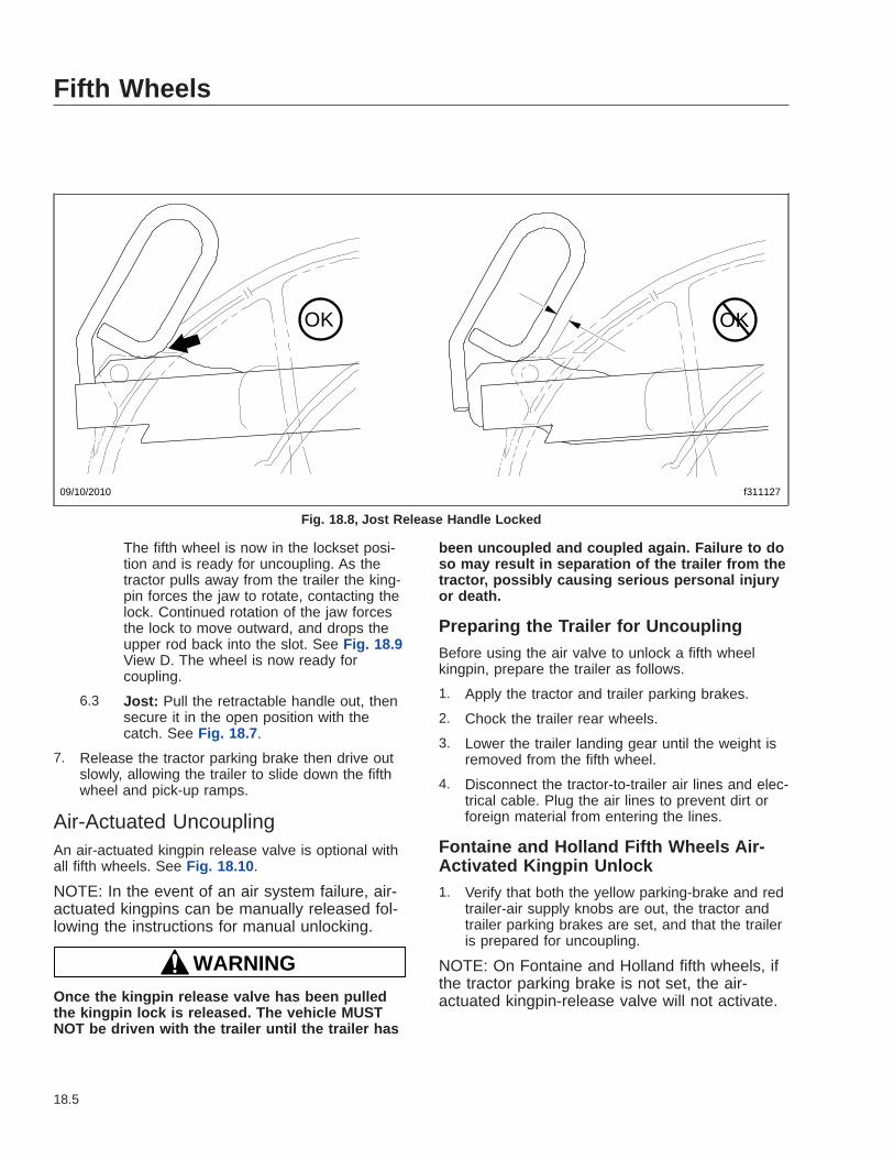
The fifth wheel is now in the lockset posi-tion and is ready for uncoupling. As thetractor pulls away from the trailer the king-pin forces the jaw to rotate, contacting thelock. Continued rotation of the jaw forcesthe lock to move outward, and drops theupper rod back into the slot. See Fig. 18.9View D. The wheel is now ready forcoupling.
6.3 Jost: Pull the retractable handle out, thensecure it in the open position with thecatch. See Fig. 18.7 .
7. Release the tractor parking brake then drive outslowly, allowing the trailer to slide down the fifthwheel and pick-up ramps.
Air-Actuated UncouplingAn air-actuated kingpin release valve is optional withall fifth wheels. See Fig. 18.10 .
NOTE: In the event of an air system failure, air-actuated kingpins can be manually released fol-lowing the instructions for manual unlocking.
WARNINGOnce the kingpin release valve has been pulledthe kingpin lock is released. The vehicle MUSTNOT be driven with the trailer until the trailer has
been uncoupled and coupled again. Failure to doso may result in separation of the trailer from thetractor, possibly causing serious personal injuryor death.
Preparing the Trailer for UncouplingBefore using the air valve to unlock a fifth wheelkingpin, prepare the trailer as follows.
1. Apply the tractor and trailer parking brakes.
2. Chock the trailer rear wheels.
3. Lower the trailer landing gear until the weight isremoved from the fifth wheel.
4. Disconnect the tractor-to-trailer air lines and elec-trical cable. Plug the air lines to prevent dirt orforeign material from entering the lines.
Fontaine and Holland Fifth Wheels Air-Activated Kingpin Unlock1. Verify that both the yellow parking-brake and red
trailer-air supply knobs are out, the tractor andtrailer parking brakes are set, and that the traileris prepared for uncoupling.
NOTE: On Fontaine and Holland fifth wheels, ifthe tractor parking brake is not set, the air-actuated kingpin-release valve will not activate.
09/10/2010 f311127
OK OK
Fig. 18.8, Jost Release Handle Locked
Fifth Wheels
18.5
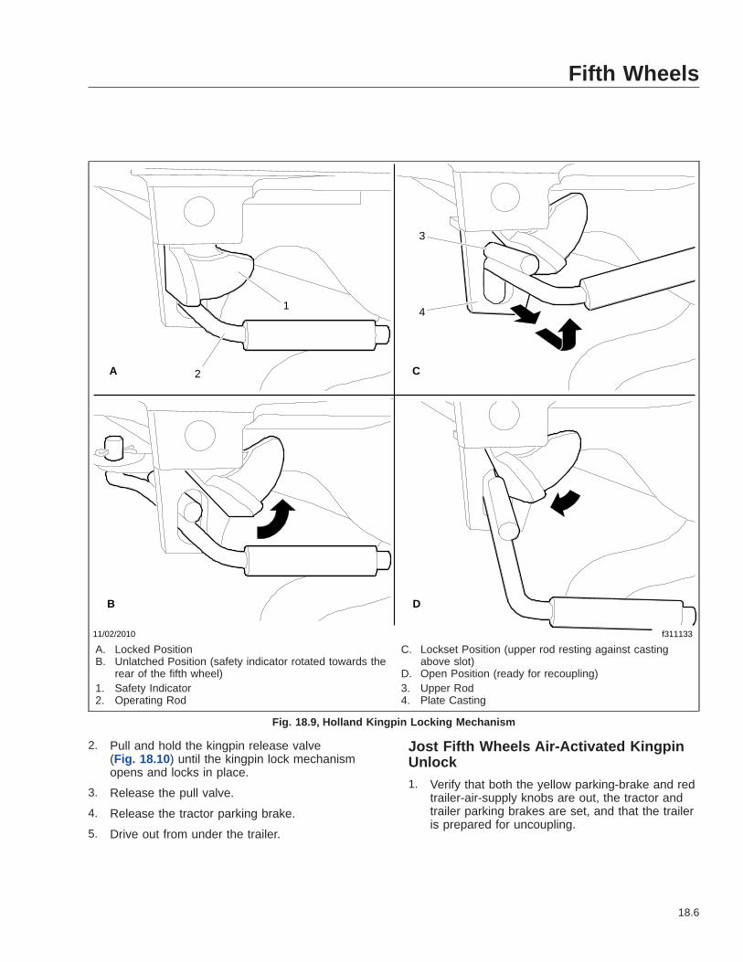
2. Pull and hold the kingpin release valve(Fig. 18.10 ) until the kingpin lock mechanismopens and locks in place.
3. Release the pull valve.
4. Release the tractor parking brake.
5. Drive out from under the trailer.
Jost Fifth Wheels Air-Activated KingpinUnlock1. Verify that both the yellow parking-brake and red
trailer-air-supply knobs are out, the tractor andtrailer parking brakes are set, and that the traileris prepared for uncoupling.
11/02/2010 f311133
A
B
C
D
1
2
3
4
A. Locked PositionB. Unlatched Position (safety indicator rotated towards the
rear of the fifth wheel)
C. Lockset Position (upper rod resting against castingabove slot)
D. Open Position (ready for recoupling)1. Safety Indicator2. Operating Rod
3. Upper Rod4. Plate Casting
Fig. 18.9, Holland Kingpin Locking Mechanism
Fifth Wheels
18.6
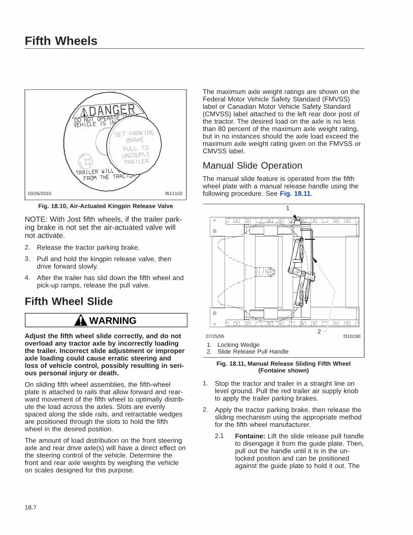
NOTE: With Jost fifth wheels, if the trailer park-ing brake is not set the air-actuated valve willnot activate.
2. Release the tractor parking brake.
3. Pull and hold the kingpin release valve, thendrive forward slowly.
4. After the trailer has slid down the fifth wheel andpick-up ramps, release the pull valve.
Fifth Wheel Slide
WARNINGAdjust the fifth wheel slide correctly, and do notoverload any tractor axle by incorrectly loadingthe trailer. Incorrect slide adjustment or improperaxle loading could cause erratic steering andloss of vehicle control, possibly resulting in seri-ous personal injury or death.
On sliding fifth wheel assemblies, the fifth-wheelplate is attached to rails that allow forward and rear-ward movement of the fifth wheel to optimally distrib-ute the load across the axles. Slots are evenlyspaced along the slide rails, and retractable wedgesare positioned through the slots to hold the fifthwheel in the desired position.
The amount of load distribution on the front steeringaxle and rear drive axle(s) will have a direct effect onthe steering control of the vehicle. Determine thefront and rear axle weights by weighing the vehicleon scales designed for this purpose.
The maximum axle weight ratings are shown on theFederal Motor Vehicle Safety Standard (FMVSS)label or Canadian Motor Vehicle Safety Standard(CMVSS) label attached to the left rear door post ofthe tractor. The desired load on the axle is no lessthan 80 percent of the maximum axle weight rating,but in no instances should the axle load exceed themaximum axle weight rating given on the FMVSS orCMVSS label.
Manual Slide OperationThe manual slide feature is operated from the fifthwheel plate with a manual release handle using thefollowing procedure. See Fig. 18.11 .
1. Stop the tractor and trailer in a straight line onlevel ground. Pull the red trailer air supply knobto apply the trailer parking brakes.
2. Apply the tractor parking brake, then release thesliding mechanism using the appropriate methodfor the fifth wheel manufacturer.
2.1 Fontaine: Lift the slide release pull handleto disengage it from the guide plate. Then,pull out the handle until it is in the un-locked position and can be positionedagainst the guide plate to hold it out. The
10/26/2010 f611102
Fig. 18.10, Air-Actuated Kingpin Release Valve
07/25/95 f310190
1
2
1. Locking Wedge2. Slide Release Pull Handle
Fig. 18.11, Manual Release Sliding Fifth Wheel(Fontaine shown)
Fifth Wheels
18.7
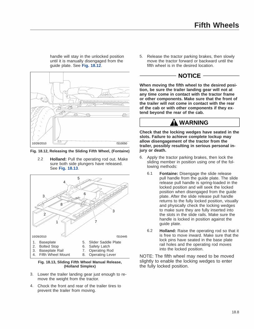
handle will stay in the unlocked positionuntil it is manually disengaged from theguide plate. See Fig. 18.12 .
2.2 Holland: Pull the operating rod out. Makesure both side plungers have released.See Fig. 18.13 .
3. Lower the trailer landing gear just enough to re-move the weight from the tractor.
4. Chock the front and rear of the trailer tires toprevent the trailer from moving.
5. Release the tractor parking brakes, then slowlymove the tractor forward or backward until thefifth wheel is in the desired location.
NOTICEWhen moving the fifth wheel to the desired posi-tion, be sure the trailer landing gear will not atany time come in contact with the tractor frameor other components. Make sure that the front ofthe trailer will not come in contact with the rearof the cab or with other components if they ex-tend beyond the rear of the cab.
WARNINGCheck that the locking wedges have seated in theslots. Failure to achieve complete lockup mayallow disengagement of the tractor from thetrailer, possibly resulting in serious personal in-jury or death.
6. Apply the tractor parking brakes, then lock thesliding member in position using one of the fol-lowing methods:
6.1 Fontaine: Disengage the slide releasepull handle from the guide plate. The sliderelease pull handle is spring-loaded in thelocked position and will seek the lockedposition when disengaged from the guideplate. After the slide release pull handlereturns to the fully locked position, visuallyand physically check the locking wedgesto make sure they are fully inserted intothe slots in the slide rails. Make sure thehandle is locked in position against theguide plate.
6.2 Holland: Raise the operating rod so that itis free to move inward. Make sure that thelock pins have seated in the base platerail holes and the operating rod movesinto the locked position.
NOTE: The fifth wheel may need to be movedslightly to enable the locking wedges to enterthe fully locked position.
10/26/2010 f310050
Fig. 18.12, Releasing the Sliding Fifth Wheel, (Fontaine)
1
2
3
45
6
3
10/26/2010 f310445
7
8
1. Baseplate2. Bolted Stop3. Baseplate Rail4. Fifth Wheel Mount
5. Slider Saddle Plate6. Safety Latch7. Operating Rod8. Operating Lever
Fig. 18.13, Sliding Fifth Wheel Manual Release,(Holland Simplex)
Fifth Wheels
18.8
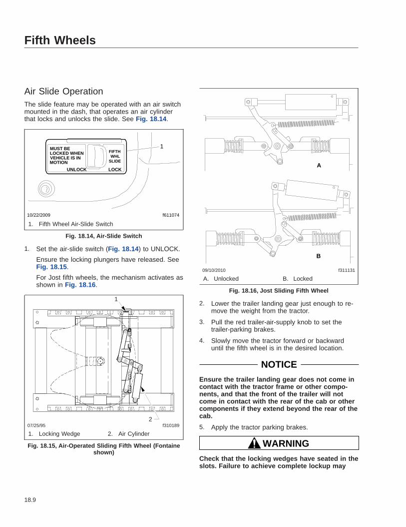
Air Slide OperationThe slide feature may be operated with an air switchmounted in the dash, that operates an air cylinderthat locks and unlocks the slide. See Fig. 18.14 .
1. Set the air-slide switch (Fig. 18.14 ) to UNLOCK.
Ensure the locking plungers have released. SeeFig. 18.15 .
For Jost fifth wheels, the mechanism activates asshown in Fig. 18.16 .
2. Lower the trailer landing gear just enough to re-move the weight from the tractor.
3. Pull the red trailer-air-supply knob to set thetrailer-parking brakes.
4. Slowly move the tractor forward or backwarduntil the fifth wheel is in the desired location.
NOTICEEnsure the trailer landing gear does not come incontact with the tractor frame or other compo-nents, and that the front of the trailer will notcome in contact with the rear of the cab or othercomponents if they extend beyond the rear of thecab.
5. Apply the tractor parking brakes.
WARNINGCheck that the locking wedges have seated in theslots. Failure to achieve complete lockup may
LOCKUNLOCK
FIFTHWHL
SLIDE
MUST BELOCKED WHENVEHICLE IS INMOTION
10/22/2009 f611074
1
1. Fifth Wheel Air-Slide Switch
Fig. 18.14, Air-Slide Switch
07/25/95 f310189
1
2
1. Locking Wedge 2. Air Cylinder
Fig. 18.15, Air-Operated Sliding Fifth Wheel (Fontaineshown)
09/10/2010 f311131
A
B
A. Unlocked B. Locked
Fig. 18.16, Jost Sliding Fifth Wheel
Fifth Wheels
18.9
allow disengagement of the tractor from thetrailer, possibly resulting in serious personal in-jury or death.
6. Set the air-slide switch to LOCK. Visually inspectthe locking wedges or plungers to make surethat they are fully inserted in the slide rail slots.Verify that the plungers have engaged by tuggingthe tractor forward while the trailer brakes arelocked and the wheels are chocked.
NOTE: The fifth wheel may need to be movedslightly to enable the locking wedges to fullylock.
Fifth Wheels
18.10
19
Trailer CouplingsAir-Suspension Dump Valve . . . . . . . . . . . . . . . . . . . . . . . . . . . . . . . . . . . . . . . . . . . . . . . . . . . . . . . . 19.1Holland Trailer Coupling . . . . . . . . . . . . . . . . . . . . . . . . . . . . . . . . . . . . . . . . . . . . . . . . . . . . . . . . . . . 19.1
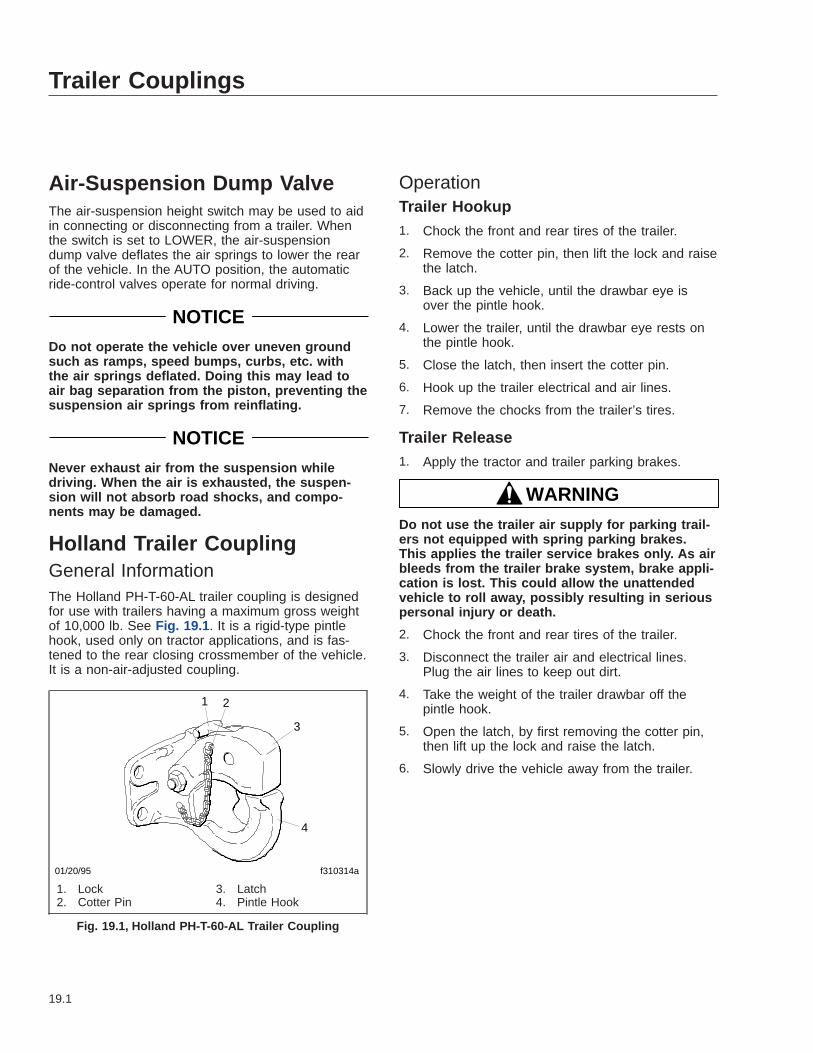
Air-Suspension Dump ValveThe air-suspension height switch may be used to aidin connecting or disconnecting from a trailer. Whenthe switch is set to LOWER, the air-suspensiondump valve deflates the air springs to lower the rearof the vehicle. In the AUTO position, the automaticride-control valves operate for normal driving.
NOTICEDo not operate the vehicle over uneven groundsuch as ramps, speed bumps, curbs, etc. withthe air springs deflated. Doing this may lead toair bag separation from the piston, preventing thesuspension air springs from reinflating.
NOTICENever exhaust air from the suspension whiledriving. When the air is exhausted, the suspen-sion will not absorb road shocks, and compo-nents may be damaged.
Holland Trailer CouplingGeneral InformationThe Holland PH-T-60-AL trailer coupling is designedfor use with trailers having a maximum gross weightof 10,000 lb. See Fig. 19.1 . It is a rigid-type pintlehook, used only on tractor applications, and is fas-tened to the rear closing crossmember of the vehicle.It is a non-air-adjusted coupling.
OperationTrailer Hookup1. Chock the front and rear tires of the trailer.
2. Remove the cotter pin, then lift the lock and raisethe latch.
3. Back up the vehicle, until the drawbar eye isover the pintle hook.
4. Lower the trailer, until the drawbar eye rests onthe pintle hook.
5. Close the latch, then insert the cotter pin.
6. Hook up the trailer electrical and air lines.
7. Remove the chocks from the trailer’s tires.
Trailer Release1. Apply the tractor and trailer parking brakes.
WARNINGDo not use the trailer air supply for parking trail-ers not equipped with spring parking brakes.This applies the trailer service brakes only. As airbleeds from the trailer brake system, brake appli-cation is lost. This could allow the unattendedvehicle to roll away, possibly resulting in seriouspersonal injury or death.
2. Chock the front and rear tires of the trailer.
3. Disconnect the trailer air and electrical lines.Plug the air lines to keep out dirt.
4. Take the weight of the trailer drawbar off thepintle hook.
5. Open the latch, by first removing the cotter pin,then lift up the lock and raise the latch.
6. Slowly drive the vehicle away from the trailer.
1 2
3
4
01/20/95 f310314a
1. Lock2. Cotter Pin
3. Latch4. Pintle Hook
Fig. 19.1, Holland PH-T-60-AL Trailer Coupling
Trailer Couplings
19.1
20
Pre- and Post-TripChecklists
Daily Pretrip Checklist . . . . . . . . . . . . . . . . . . . . . . . . . . . . . . . . . . . . . . . . . . . . . . . . . . . . . . . . . . . . 20.1Weekly Post-Trip Checklist . . . . . . . . . . . . . . . . . . . . . . . . . . . . . . . . . . . . . . . . . . . . . . . . . . . . . . . . . 20.3Monthly Post-Trip Checklist . . . . . . . . . . . . . . . . . . . . . . . . . . . . . . . . . . . . . . . . . . . . . . . . . . . . . . . . 20.3
Daily Pretrip ChecklistRegulations in both Canada and the United Statesclearly indicate that it is the driver’s responsibility toperform an inspection, and ensure the completeroad-worthiness of a vehicle, before placing it intoservice for the day. Commercial vehicles may besubject to inspection by authorized inspectors, andan unsafe vehicle can be put "out of service" until thedriver or owner repairs it.
IMPORTANT: The pre- and post-trip checklists,and inspections and maintenance proceduresdetailed in this chapter, are not all-inclusive .Also refer to other component and body manu-facturers’ instructions for specific inspection andmaintenance instructions.
Careful inspections save time by eliminating stopslater to adjust items overlooked or forgotten. Use theinspection checklists to ensure that vehicle compo-nents are in good working condition before each trip.A driver that is familiar with the vehicle, and drives itregularly, can perform the daily inspections, then addthe weekly and monthly post-trip inspections asscheduled. If the driver does not operate the vehicleon a consistent basis, all three of the inspection pro-cedures should be performed before the trip.
The checklists in this chapter can be copied and thefirst column marked with a check mark to indicate theprocedure has been performed. The checklist canthen be kept as a record that the procedures havebeen completed. For details on how to perform eachprocedure, see the procedure reference number inChapter 22 of this manual.
If any system or component does not pass this in-spection, it must be corrected before operating thevehicle. Whenever equipment requires adjustment,replacement, repair, addition of lubricants, or achange of lubricants, see the Cascadia™ WorkshopManual for procedures and specifications. See theCascadia™ Maintenance Manual for lubricant recom-mendations, specifications, and maintenance inter-vals.
See Table 20.1 for a list of procedures that shouldbe preformed daily, before the first trip.
IMPORTANT: Before performing any of thesechecks, apply the parking brake and chock thetires.
NOTE: Procedure reference numbers in thechecklists reference the step in Chapter 21 ,Pre- and Post-Trip Inspections and Mainte-nance. D indicates a daily pretrip procedure withthe corresponding number, W indicates aweekly post-trip procedure with the correspond-ing number, and M indicates a monthly post-tripprocedure with the corresponding number.
Pre- and Post-Trip Checklists
20.1
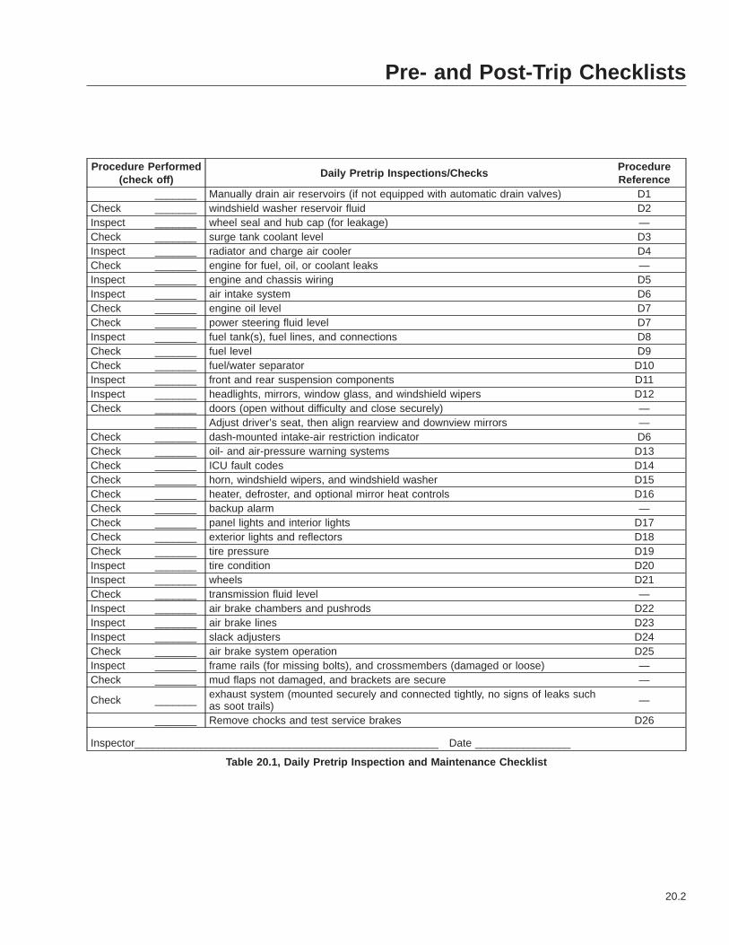
Procedure Performed(check off)
Daily Pretrip Inspections/ChecksProcedureReference
_______ Manually drain air reservoirs (if not equipped with automatic drain valves) D1Check _______ windshield washer reservoir fluid D2Inspect _______ wheel seal and hub cap (for leakage) —Check _______ surge tank coolant level D3Inspect _______ radiator and charge air cooler D4Check _______ engine for fuel, oil, or coolant leaks —Inspect _______ engine and chassis wiring D5Inspect _______ air intake system D6Check _______ engine oil level D7Check _______ power steering fluid level D7Inspect _______ fuel tank(s), fuel lines, and connections D8Check _______ fuel level D9Check _______ fuel/water separator D10Inspect _______ front and rear suspension components D11Inspect _______ headlights, mirrors, window glass, and windshield wipers D12Check _______ doors (open without difficulty and close securely) —
_______ Adjust driver’s seat, then align rearview and downview mirrors —Check _______ dash-mounted intake-air restriction indicator D6Check _______ oil- and air-pressure warning systems D13Check _______ ICU fault codes D14Check _______ horn, windshield wipers, and windshield washer D15Check _______ heater, defroster, and optional mirror heat controls D16Check _______ backup alarm —Check _______ panel lights and interior lights D17Check _______ exterior lights and reflectors D18Check _______ tire pressure D19Inspect _______ tire condition D20Inspect _______ wheels D21Check _______ transmission fluid level —Inspect _______ air brake chambers and pushrods D22Inspect _______ air brake lines D23Inspect _______ slack adjusters D24Check _______ air brake system operation D25Inspect _______ frame rails (for missing bolts), and crossmembers (damaged or loose) —Check _______ mud flaps not damaged, and brackets are secure —
Check _______ exhaust system (mounted securely and connected tightly, no signs of leaks suchas soot trails) —
_______ Remove chocks and test service brakes D26
Inspector___________________________________________________ Date ________________
Table 20.1, Daily Pretrip Inspection and Maintenance Checklist
Pre- and Post-Trip Checklists
20.2
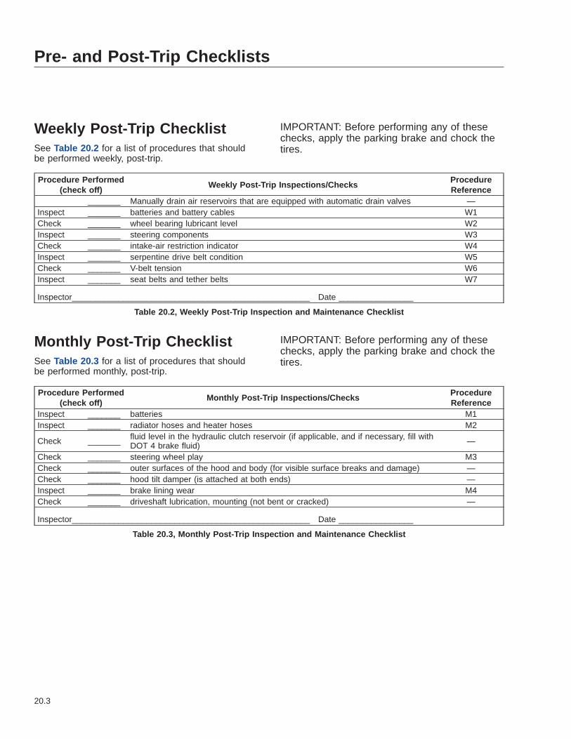
Weekly Post-Trip ChecklistSee Table 20.2 for a list of procedures that shouldbe performed weekly, post-trip.
IMPORTANT: Before performing any of thesechecks, apply the parking brake and chock thetires.
Procedure Performed(check off)
Weekly Post-Trip Inspections/ChecksProcedureReference
_______ Manually drain air reservoirs that are equipped with automatic drain valves —Inspect _______ batteries and battery cables W1Check _______ wheel bearing lubricant level W2Inspect _______ steering components W3Check _______ intake-air restriction indicator W4Inspect _______ serpentine drive belt condition W5Check _______ V-belt tension W6Inspect _______ seat belts and tether belts W7
Inspector___________________________________________________ Date ________________
Table 20.2, Weekly Post-Trip Inspection and Maintenance Checklist
Monthly Post-Trip ChecklistSee Table 20.3 for a list of procedures that shouldbe performed monthly, post-trip.
IMPORTANT: Before performing any of thesechecks, apply the parking brake and chock thetires.
Procedure Performed(check off)
Monthly Post-Trip Inspections/ChecksProcedureReference
Inspect _______ batteries M1Inspect _______ radiator hoses and heater hoses M2
Check _______ fluid level in the hydraulic clutch reservoir (if applicable, and if necessary, fill withDOT 4 brake fluid) —
Check _______ steering wheel play M3Check _______ outer surfaces of the hood and body (for visible surface breaks and damage) —Check _______ hood tilt damper (is attached at both ends) —Inspect _______ brake lining wear M4Check _______ driveshaft lubrication, mounting (not bent or cracked) —
Inspector___________________________________________________ Date ________________
Table 20.3, Monthly Post-Trip Inspection and Maintenance Checklist
Pre- and Post-Trip Checklists
20.3
21
Pre- and Post-TripInspections and
MaintenanceDaily Pretrip Inspection and Maintenance . . . . . . . . . . . . . . . . . . . . . . . . . . . . . . . . . . . . . . . . . . . . . 21.1Weekly Post-Trip Inspection and Maintenance . . . . . . . . . . . . . . . . . . . . . . . . . . . . . . . . . . . . . . . . 21.11Monthly Post-Trip Inspection and Maintenance . . . . . . . . . . . . . . . . . . . . . . . . . . . . . . . . . . . . . . . 21.13
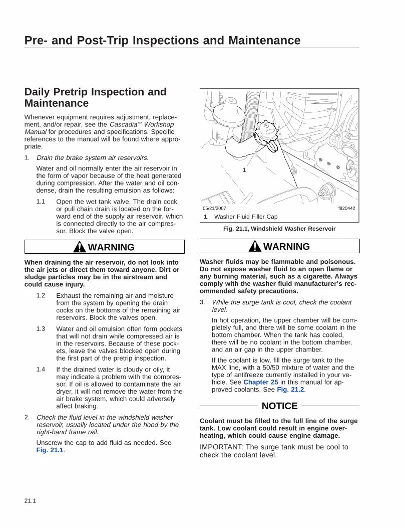
Daily Pretrip Inspection andMaintenanceWhenever equipment requires adjustment, replace-ment, and/or repair, see the Cascadia™ WorkshopManual for procedures and specifications. Specificreferences to the manual will be found where appro-priate.
1. Drain the brake system air reservoirs.
Water and oil normally enter the air reservoir inthe form of vapor because of the heat generatedduring compression. After the water and oil con-dense, drain the resulting emulsion as follows:
1.1 Open the wet tank valve. The drain cockor pull chain drain is located on the for-ward end of the supply air reservoir, whichis connected directly to the air compres-sor. Block the valve open.
WARNINGWhen draining the air reservoir, do not look intothe air jets or direct them toward anyone. Dirt orsludge particles may be in the airstream andcould cause injury.
1.2 Exhaust the remaining air and moisturefrom the system by opening the draincocks on the bottoms of the remaining airreservoirs. Block the valves open.
1.3 Water and oil emulsion often form pocketsthat will not drain while compressed air isin the reservoirs. Because of these pock-ets, leave the valves blocked open duringthe first part of the pretrip inspection.
1.4 If the drained water is cloudy or oily, itmay indicate a problem with the compres-sor. If oil is allowed to contaminate the airdryer, it will not remove the water from theair brake system, which could adverselyaffect braking.
2. Check the fluid level in the windshield washerreservoir, usually located under the hood by theright-hand frame rail.
Unscrew the cap to add fluid as needed. SeeFig. 21.1 .
WARNINGWasher fluids may be flammable and poisonous.Do not expose washer fluid to an open flame orany burning material, such as a cigarette. Alwayscomply with the washer fluid manufacturer’s rec-ommended safety precautions.
3. While the surge tank is cool, check the coolantlevel.
In hot operation, the upper chamber will be com-pletely full, and there will be some coolant in thebottom chamber. When the tank has cooled,there will be no coolant in the bottom chamber,and an air gap in the upper chamber.
If the coolant is low, fill the surge tank to theMAX line, with a 50/50 mixture of water and thetype of antifreeze currently installed in your ve-hicle. See Chapter 25 in this manual for ap-proved coolants. See Fig. 21.2 .
NOTICECoolant must be filled to the full line of the surgetank. Low coolant could result in engine over-heating, which could cause engine damage.
IMPORTANT: The surge tank must be cool tocheck the coolant level.
05/21/2007 f820442
1
1. Washer Fluid Filler Cap
Fig. 21.1, Windshield Washer Reservoir
Pre- and Post-Trip Inspections and Maintenance
21.1
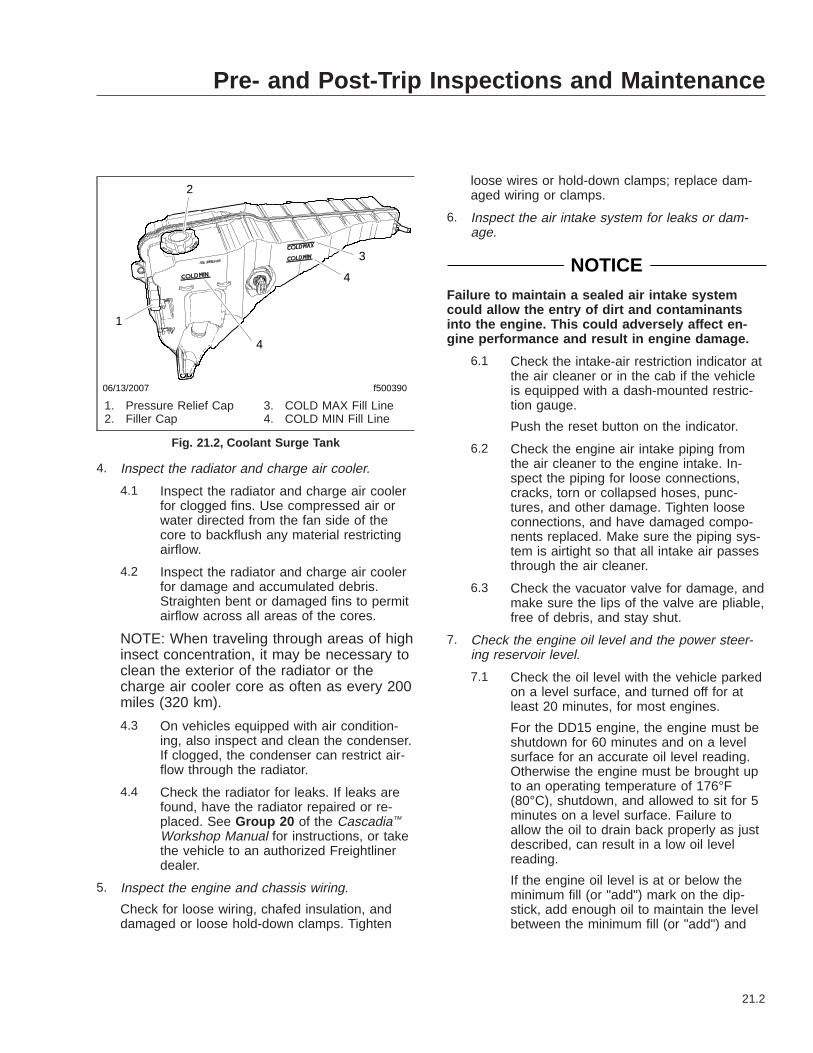
4. Inspect the radiator and charge air cooler.
4.1 Inspect the radiator and charge air coolerfor clogged fins. Use compressed air orwater directed from the fan side of thecore to backflush any material restrictingairflow.
4.2 Inspect the radiator and charge air coolerfor damage and accumulated debris.Straighten bent or damaged fins to permitairflow across all areas of the cores.
NOTE: When traveling through areas of highinsect concentration, it may be necessary toclean the exterior of the radiator or thecharge air cooler core as often as every 200miles (320 km).
4.3 On vehicles equipped with air condition-ing, also inspect and clean the condenser.If clogged, the condenser can restrict air-flow through the radiator.
4.4 Check the radiator for leaks. If leaks arefound, have the radiator repaired or re-placed. See Group 20 of the Cascadia™
Workshop Manual for instructions, or takethe vehicle to an authorized Freightlinerdealer.
5. Inspect the engine and chassis wiring.
Check for loose wiring, chafed insulation, anddamaged or loose hold-down clamps. Tighten
loose wires or hold-down clamps; replace dam-aged wiring or clamps.
6. Inspect the air intake system for leaks or dam-age.
NOTICEFailure to maintain a sealed air intake systemcould allow the entry of dirt and contaminantsinto the engine. This could adversely affect en-gine performance and result in engine damage.
6.1 Check the intake-air restriction indicator atthe air cleaner or in the cab if the vehicleis equipped with a dash-mounted restric-tion gauge.
Push the reset button on the indicator.
6.2 Check the engine air intake piping fromthe air cleaner to the engine intake. In-spect the piping for loose connections,cracks, torn or collapsed hoses, punc-tures, and other damage. Tighten looseconnections, and have damaged compo-nents replaced. Make sure the piping sys-tem is airtight so that all intake air passesthrough the air cleaner.
6.3 Check the vacuator valve for damage, andmake sure the lips of the valve are pliable,free of debris, and stay shut.
7. Check the engine oil level and the power steer-ing reservoir level.
7.1 Check the oil level with the vehicle parkedon a level surface, and turned off for atleast 20 minutes, for most engines.
For the DD15 engine, the engine must beshutdown for 60 minutes and on a levelsurface for an accurate oil level reading.Otherwise the engine must be brought upto an operating temperature of 176°F(80°C), shutdown, and allowed to sit for 5minutes on a level surface. Failure toallow the oil to drain back properly as justdescribed, can result in a low oil levelreading.
If the engine oil level is at or below theminimum fill (or "add") mark on the dip-stick, add enough oil to maintain the levelbetween the minimum fill (or "add") and
06/13/2007
1
2
f500390
3
4
4
1. Pressure Relief Cap2. Filler Cap
3. COLD MAX Fill Line4. COLD MIN Fill Line
Fig. 21.2, Coolant Surge Tank
Pre- and Post-Trip Inspections and Maintenance
21.2
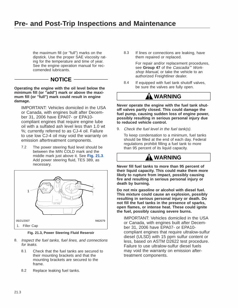
the maximum fill (or "full") marks on thedipstick. Use the proper SAE viscosity rat-ing for the temperature and time of year.See the engine operation manual for rec-comended lubricants.
NOTICEOperating the engine with the oil level below theminimum fill (or "add") mark or above the maxi-mum fill (or "full") mark could result in enginedamage.
IMPORTANT: Vehicles domiciled in the USAor Canada, with engines built after Decem-ber 31, 2006 have EPA07- or EPA10-compliant engines that require engine lubeoil with a sulfated ash level less than 1.0 wt%; currently referred to as CJ-4 oil. Failureto use low CJ-4 oil may void the warranty onemission aftertreatment components.
7.2 The power steering fluid level should bebetween the MIN COLD mark and themiddle mark just above it. See Fig. 21.3 .Add power steering fluid, TES 389, asnecessary.
8. Inspect the fuel tanks, fuel lines, and connectionsfor leaks.
8.1 Check that the fuel tanks are secured totheir mounting brackets and that themounting brackets are secured to theframe.
8.2 Replace leaking fuel tanks.
8.3 If lines or connections are leaking, havethem repaired or replaced.
For repair and/or replacement procedures,see Group 47 of the Cascadia™ Work-shop Manual, or take the vehicle to anauthorized Freightliner dealer.
8.4 If equipped with fuel tank shutoff valves,be sure the valves are fully open.
WARNINGNever operate the engine with the fuel tank shut-off valves partly closed. This could damage thefuel pump, causing sudden loss of engine power,possibly resulting in serious personal injury dueto reduced vehicle control.
9. Check the fuel level in the fuel tank(s).
To keep condensation to a minimum, fuel tanksshould be filled at the end of each day. Federalregulations prohibit filling a fuel tank to morethan 95 percent of its liquid capacity.
WARNINGNever fill fuel tanks to more than 95 percent oftheir liquid capacity. This could make them morelikely to rupture from impact, possibly causingfire and resulting in serious personal injury ordeath by burning.
Do not mix gasoline or alcohol with diesel fuel.This mixture could cause an explosion, possiblyresulting in serious personal injury or death. Donot fill the fuel tanks in the presence of sparks,open flames, or intense heat. These could ignitethe fuel, possibly causing severe burns.
IMPORTANT: Vehicles domiciled in the USAor Canada, with engines built after Decem-ber 31, 2006 have EPA07- or EPA10-compliant engines that require ultralow-sulfurdiesel (ULSD) with 15 ppm sulfur content orless, based on ASTM D2622 test procedure.Failure to use ultralow-sulfur diesel fuelsmay void the warranty on emission after-treatment components.
05/21/2007
1
f462079
1. Filler Cap
Fig. 21.3, Power Steering Fluid Reseroir
Pre- and Post-Trip Inspections and Maintenance
21.3
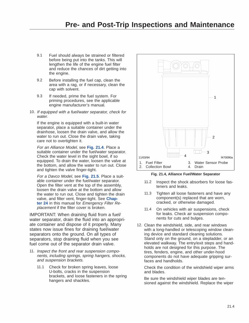
9.1 Fuel should always be strained or filteredbefore being put into the tanks. This willlengthen the life of the engine fuel filterand reduce the chances of dirt getting intothe engine.
9.2 Before installing the fuel cap, clean thearea with a rag, or if necessary, clean thecap with solvent.
9.3 If needed, prime the fuel system. Forpriming procedures, see the applicableengine manufacturer’s manual.
10. If equipped with a fuel/water separator, check forwater.
If the engine is equipped with a built-in waterseparator, place a suitable container under thedrainhose, loosen the drain valve, and allow thewater to run out. Close the drain valve, takingcare not to overtighten it.
For an Alliance Model, see Fig. 21.4 . Place asuitable container under the fuel/water separator.Check the water level in the sight bowl, if soequipped. To drain the water, loosen the valve atthe bottom, and allow the water to run out. Closeand tighten the valve finger-tight.
For a Davco Model, see Fig. 21.5 . Place a suit-able container under the fuel/water separator.Open the filter vent at the top of the assembly,loosen the drain valve at the bottom and allowthe water to run out. Close and tighten the drainvalve, and filter vent, finger-tight. See Chap-ter 24 in this manual for Emergency Filter Re-placement if the filter cover is broken.
IMPORTANT: When draining fluid from a fuel/water separator, drain the fluid into an appropri-ate container and dispose of it properly. Manystates now issue fines for draining fuel/waterseparators onto the ground. On all types ofseparators, stop draining fluid when you seefuel come out of the separator drain valve.
11. Inspect the front and rear suspension compo-nents, including springs, spring hangers, shocks,and suspension brackets.
11.1 Check for broken spring leaves, looseU-bolts, cracks in the suspensionbrackets, and loose fasteners in the springhangers and shackles.
11.2 Inspect the shock absorbers for loose fas-teners and leaks.
11.3 Tighten all loose fasteners and have anycomponent(s) replaced that are worn,cracked, or otherwise damaged.
11.4 On vehicles with air suspensions, checkfor leaks. Check air suspension compo-nents for cuts and bulges.
12. Clean the windshield, side, and rear windowswith a long-handled or telescoping window clean-ing device and standard cleaning solutions.Stand only on the ground, on a stepladder, or anelevated walkway. The entry/exit steps and hand-holds are not designed for this purpose. Thetires, fenders, engine, and other under-hoodcomponents do not have adequate gripping sur-faces and handholds.
Check the condition of the windshield wiper armsand blades.
Be sure the windshield wiper blades are ten-sioned against the windshield. Replace the wiper
1
2
4 f470090a
311/03/94
1. Fuel Filter2. Collection Bowl
3. Water Sensor Probe4. Drain
Fig. 21.4, Alliance Fuel/Water Separator
Pre- and Post-Trip Inspections and Maintenance
21.4
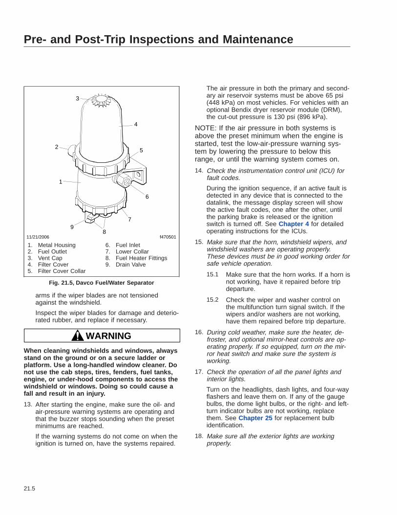
arms if the wiper blades are not tensionedagainst the windshield.
Inspect the wiper blades for damage and deterio-rated rubber, and replace if necessary.
WARNINGWhen cleaning windshields and windows, alwaysstand on the ground or on a secure ladder orplatform. Use a long-handled window cleaner. Donot use the cab steps, tires, fenders, fuel tanks,engine, or under-hood components to access thewindshield or windows. Doing so could cause afall and result in an injury.
13. After starting the engine, make sure the oil- andair-pressure warning systems are operating andthat the buzzer stops sounding when the presetminimums are reached.
If the warning systems do not come on when theignition is turned on, have the systems repaired.
The air pressure in both the primary and second-ary air reservoir systems must be above 65 psi(448 kPa) on most vehicles. For vehicles with anoptional Bendix dryer reservoir module (DRM),the cut-out pressure is 130 psi (896 kPa).
NOTE: If the air pressure in both systems isabove the preset minimum when the engine isstarted, test the low-air-pressure warning sys-tem by lowering the pressure to below thisrange, or until the warning system comes on.
14. Check the instrumentation control unit (ICU) forfault codes.
During the ignition sequence, if an active fault isdetected in any device that is connected to thedatalink, the message display screen will showthe active fault codes, one after the other, untilthe parking brake is released or the ignitionswitch is turned off. See Chapter 4 for detailedoperating instructions for the ICUs.
15. Make sure that the horn, windshield wipers, andwindshield washers are operating properly.These devices must be in good working order forsafe vehicle operation.
15.1 Make sure that the horn works. If a horn isnot working, have it repaired before tripdeparture.
15.2 Check the wiper and washer control onthe multifunction turn signal switch. If thewipers and/or washers are not working,have them repaired before trip departure.
16. During cold weather, make sure the heater, de-froster, and optional mirror-heat controls are op-erating properly. If so equipped, turn on the mir-ror heat switch and make sure the system isworking.
17. Check the operation of all the panel lights andinterior lights.
Turn on the headlights, dash lights, and four-wayflashers and leave them on. If any of the gaugebulbs, the dome light bulbs, or the right- and left-turn indicator bulbs are not working, replacethem. See Chapter 25 for replacement bulbidentification.
18. Make sure all the exterior lights are workingproperly.
11/21/2006 f470501
2
1
3
4
5
6
7
89
1. Metal Housing2. Fuel Outlet3. Vent Cap4. Filter Cover5. Filter Cover Collar
6. Fuel Inlet7. Lower Collar8. Fuel Heater Fittings9. Drain Valve
Fig. 21.5, Davco Fuel/Water Separator
Pre- and Post-Trip Inspections and Maintenance
21.5
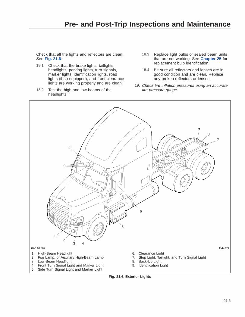
Check that all the lights and reflectors are clean.See Fig. 21.6 .
18.1 Check that the brake lights, taillights,headlights, parking lights, turn signals,marker lights, identification lights, roadlights (if so equipped), and front clearancelights are working properly and are clean.
18.2 Test the high and low beams of theheadlights.
18.3 Replace light bulbs or sealed beam unitsthat are not working. See Chapter 25 forreplacement bulb identification.
18.4 Be sure all reflectors and lenses are ingood condition and are clean. Replaceany broken reflectors or lenses.
19. Check tire inflation pressures using an accuratetire pressure gauge.
02/14/2007 f544971
12
3 4
5
6
6
7
78
9
1. High-Beam Headlight2. Fog Lamp, or Auxiliary High-Beam Lamp3. Low-Beam Headlight4. Front Turn Signal Light and Marker Light5. Side Turn Signal Light and Marker Light
6. Clearance Light7. Stop Light, Taillight, and Turn Signal Light8. Back-Up Light9. Identification Light
Fig. 21.6, Exterior Lights
Pre- and Post-Trip Inspections and Maintenance
21.6
Tires should be checked when cool. For inflationpressures and maximum loads (per tire) see thetire manufacturer’s guidelines.
19.1 Be sure valve stem caps are on every tireand that they are screwed on finger-tight.
19.2 Inflate the tires to the applicable pressuresif needed.
19.3 If a tire has been run flat or underinflated,check the wheel and tire for damage be-fore adding air.
Moisture inside a tire can result in bodyply separation or a sidewall rupture. Dur-ing tire inflation, compressed air reservoirsand lines must be kept dry. Use well-maintained inline moisture traps and ser-vice them regularly.
WARNINGDo not operate the vehicle with underinflated oroverinflated tires. Incorrect inflation can stressthe tires and make the tires and rims more sus-ceptible to damage, possibly leading to rim ortire failure and loss of vehicle control, resultingin serious personal injury or death.
IMPORTANT: The load and cold inflation pres-sure must not exceed the wheel manufacturer’srecommendations, even though the tire may beapproved for a higher load inflation. Somewheels are stamped with a maximum load andmaximum cold inflation rating. If they are notstamped, consult the manufacturer for the cor-rect tire inflation pressure for the vehicle load. Ifthe load exceeds the maximum rim capacity, theload must be adjusted or reduced.
CAUTIONA weekly pressure loss of 4 psi (28 kPa) or morein a tire may indicate damage. The tire should beinspected and, if necessary, repaired or replaced.
20. Inspect each tire for wear, bulges, cracks, cuts,penetrations, and oil contamination.
20.1 Check the tire tread depth. If tread is lessthan 4/32 inch (3 mm) on any front tire, orless than 2/32 inch (1.5 mm) on any reartire, replace the tire.
20.2 Inspect each tire for bulges, cracks, cuts,and penetrations.
20.3 Inspect each tire for oil contamination.Fuel oil, gasoline, and other petroleumderivatives, if allowed to contact the tires,will soften the rubber and destroy the tire.
21. Check the wheel nuts for indications of loose-ness. Examine each rim and wheel component.
21.1 Remove all dirt and foreign material fromthe assembly.
21.2 Examine the wheel assembly componentsfor cracks, or other damage.
See Group 33 or Group 35 of the Casca-dia™ Workshop Manual for service proce-dures on the studs and hubs, and seeGroup 40 in the same manual for wheeland tire servicing, or take the vehicle to anauthorized Freightliner dealer.
WARNINGHave any worn or damaged wheel componentsreplaced by a qualified person using the wheelmanufacturer’s instructions and the wheel indus-try’s standard safety precautions and equipment.Otherwise a vehicle or workshop accident couldoccur, possibly resulting in serious personal in-jury or death.
NOTICEInsufficient wheel nut torque can cause wheelshimmy, resulting in wheel damage, stud break-age, and extreme tire tread wear. Excessivewheel nut torque can break studs, damagethreads, and crack discs in the stud hole area.Use the recommended torque values and followthe proper tightening sequence.
21.3 Make sure all wheel nuts are tightened450 to 500 lbf·ft (610 to 678 N·m) for Ac-curide wheels with unlubricated threads.
Use the tightening pattern in Fig. 21.7 for10-hole wheels. See Group 40 of theCascadia™ Workshop Manual for moreinformation.
22. Inspect the air brake chamber and the air brakechamber pushrods.
Pre- and Post-Trip Inspections and Maintenance
21.7
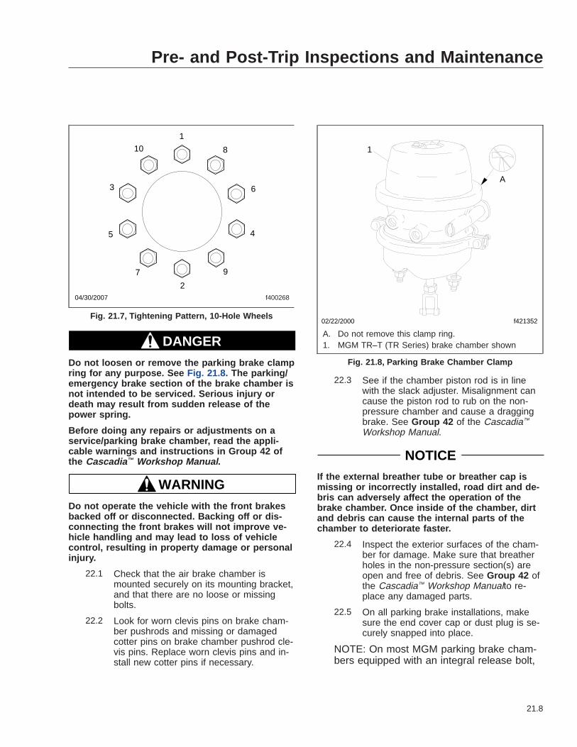
DANGERDo not loosen or remove the parking brake clampring for any purpose. See Fig. 21.8. The parking/emergency brake section of the brake chamber isnot intended to be serviced. Serious injury ordeath may result from sudden release of thepower spring.
Before doing any repairs or adjustments on aservice/parking brake chamber, read the appli-cable warnings and instructions in Group 42 ofthe Cascadia ™ Workshop Manual .
WARNINGDo not operate the vehicle with the front brakesbacked off or disconnected. Backing off or dis-connecting the front brakes will not improve ve-hicle handling and may lead to loss of vehiclecontrol, resulting in property damage or personalinjury.
22.1 Check that the air brake chamber ismounted securely on its mounting bracket,and that there are no loose or missingbolts.
22.2 Look for worn clevis pins on brake cham-ber pushrods and missing or damagedcotter pins on brake chamber pushrod cle-vis pins. Replace worn clevis pins and in-stall new cotter pins if necessary.
22.3 See if the chamber piston rod is in linewith the slack adjuster. Misalignment cancause the piston rod to rub on the non-pressure chamber and cause a draggingbrake. See Group 42 of the Cascadia™
Workshop Manual.
NOTICEIf the external breather tube or breather cap ismissing or incorrectly installed, road dirt and de-bris can adversely affect the operation of thebrake chamber. Once inside of the chamber, dirtand debris can cause the internal parts of thechamber to deteriorate faster.
22.4 Inspect the exterior surfaces of the cham-ber for damage. Make sure that breatherholes in the non-pressure section(s) areopen and free of debris. See Group 42 ofthe Cascadia™ Workshop Manualto re-place any damaged parts.
22.5 On all parking brake installations, makesure the end cover cap or dust plug is se-curely snapped into place.
NOTE: On most MGM parking brake cham-bers equipped with an integral release bolt,
f400268
1
10 8
6
4
9
2
7
5
3
04/30/2007
Fig. 21.7, Tightening Pattern, 10-Hole Wheels
1
A
02/22/2000 f421352
A. Do not remove this clamp ring.1. MGM TR–T (TR Series) brake chamber shown
Fig. 21.8, Parking Brake Chamber Clamp
Pre- and Post-Trip Inspections and Maintenance
21.8
an end cover cap is installed over the re-lease bolt.
22.6 Check for rusted connections, missingsnap rings, and damaged camshaftgrease seals. Have damaged or missingparts repaired or replaced.
23. Inspect the air brake lines.
23.1 Check the clearance between the hosesand the exhaust manifold or other hotspots. Excessive heat will cause materialin the hoses to deteriorate rapidly or be-come brittle. Provide at least 6 inches(150 mm) of clearance. More clearance isrecommended if the hose is located abovethe heat source.
23.2 Check for kinks, dents, or swelling of thehoses. If damaged, have the hose re-placed with the same size and type.
NOTE: Do not route the hose on top of any-thing likely to be stepped on.
23.3 Check for damage to hoses located nearmoving parts, such as drivelines, kingpins,suspensions, and axles. If moving partsare catching or pinching the lines, correctas needed.
23.4 Check for hose damage caused by abra-sion. If abraded, have the hose replaced.Check for the cause of abrasion, such asloose or damaged hose clamps. Have theclamps repaired or replaced as needed.
23.5 Observe the hose cover condition, espe-cially hoses exposed to water splash andice. If dried out or ragged (the wire or lineris showing through the cover), have thehose(s) replaced.
23.6 Inspect the air tubing, especially tubingmade of nylon. In cold weather, nylon tub-ing is sensitive to damage, such as nicksor cuts. Have nicked or cut tubing re-placed, even if it is not leaking.
23.7 Check for kinked or twisted hoses. Aseven-percent twist in the hose can re-duce its life by up to 90 percent. A twistedhose under pressure tends to untwist,which may loosen the fitting. Reconnecthoses that are twisted.
NOTE: The front brake lines flex continu-ously in vehicle operation, so they requirespecial examination. Give particular attentionto the areas near where they connect to thefront air brake chambers. This inspectionrequires two people, one in the driver seatand another to inspect the brake line con-nections at the wheels.
23.8 Both wheel air lines must be inspectedwith the emergency brake set, engineidling, air pressure at 80 to 90 psi (550 to620 kPa), and the brake pedal held down.
23.9 Turn the wheels to full lock in one direc-tion and inspect both air lines where theyconnect to the air chambers, then turn thewheels to full lock in the other directionand inspect both lines. If a hose is leak-ing, have it replaced.
IMPORTANT: ABS-equipped vehicles operat-ing in regions where especially corrosiveice-removal chemicals are used may experi-ence higher than normal rotor corrosion.Tone rings should be routinely inspected forcorrosion. Severe corrosion of the integralABS tone ring may cause the ABS warninglamp in the dash to illuminate due to falsewheel speed readings. If the ABS warninglamp illuminates at any time other than atvehicle start-up, have the problem repairedimmediately.
24. Inspect the slack adjusters.
24.1 Meritor Slack Adjusters: Check the bootfor cuts, tears, or other damage. Have itreplaced if necessary.
24.2 Gunite Slack Adjusters: Inspect the slackadjuster for any signs of damage. If dam-aged, have the slack adjuster replaced.
Inspect the slack adjuster boot for cuts ortears. If the boot is damaged, have it re-placed. See Fig. 21.9 .
24.3 Haldex Slack Adjusters: Inspect eachslack adjuster and anchor strap for dam-age. Replace any damaged components.
25. Check the air brake system for proper operation.
Pre- and Post-Trip Inspections and Maintenance
21.9
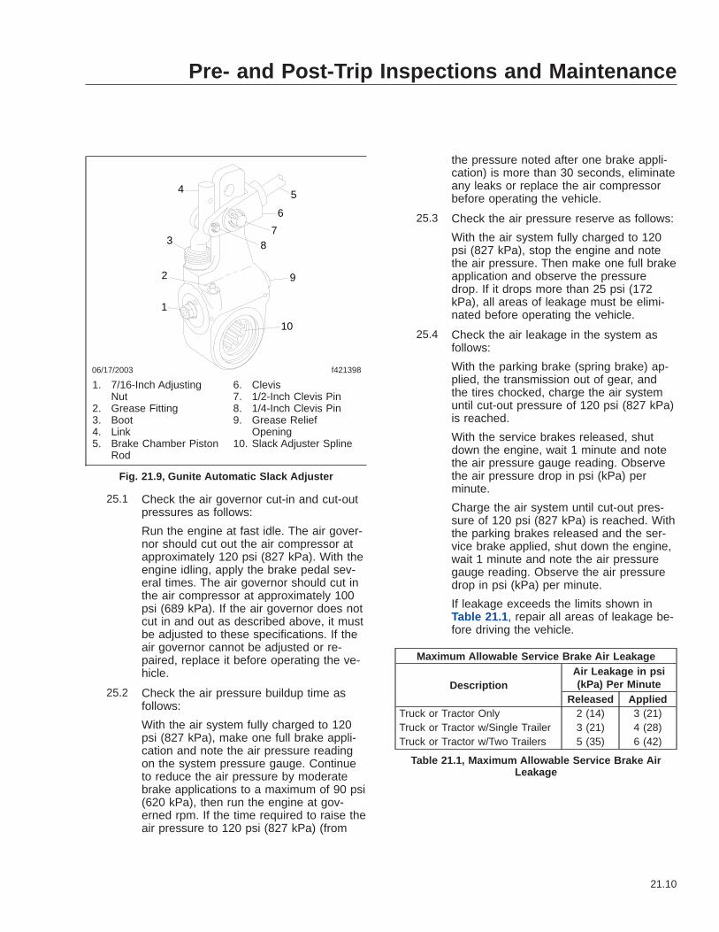
25.1 Check the air governor cut-in and cut-outpressures as follows:
Run the engine at fast idle. The air gover-nor should cut out the air compressor atapproximately 120 psi (827 kPa). With theengine idling, apply the brake pedal sev-eral times. The air governor should cut inthe air compressor at approximately 100psi (689 kPa). If the air governor does notcut in and out as described above, it mustbe adjusted to these specifications. If theair governor cannot be adjusted or re-paired, replace it before operating the ve-hicle.
25.2 Check the air pressure buildup time asfollows:
With the air system fully charged to 120psi (827 kPa), make one full brake appli-cation and note the air pressure readingon the system pressure gauge. Continueto reduce the air pressure by moderatebrake applications to a maximum of 90 psi(620 kPa), then run the engine at gov-erned rpm. If the time required to raise theair pressure to 120 psi (827 kPa) (from
the pressure noted after one brake appli-cation) is more than 30 seconds, eliminateany leaks or replace the air compressorbefore operating the vehicle.
25.3 Check the air pressure reserve as follows:
With the air system fully charged to 120psi (827 kPa), stop the engine and notethe air pressure. Then make one full brakeapplication and observe the pressuredrop. If it drops more than 25 psi (172kPa), all areas of leakage must be elimi-nated before operating the vehicle.
25.4 Check the air leakage in the system asfollows:
With the parking brake (spring brake) ap-plied, the transmission out of gear, andthe tires chocked, charge the air systemuntil cut-out pressure of 120 psi (827 kPa)is reached.
With the service brakes released, shutdown the engine, wait 1 minute and notethe air pressure gauge reading. Observethe air pressure drop in psi (kPa) perminute.
Charge the air system until cut-out pres-sure of 120 psi (827 kPa) is reached. Withthe parking brakes released and the ser-vice brake applied, shut down the engine,wait 1 minute and note the air pressuregauge reading. Observe the air pressuredrop in psi (kPa) per minute.
If leakage exceeds the limits shown inTable 21.1 , repair all areas of leakage be-fore driving the vehicle.
Maximum Allowable Service Brake Air Leakage
DescriptionAir Leakage in psi(kPa) Per Minute
Released AppliedTruck or Tractor Only 2 (14) 3 (21)Truck or Tractor w/Single Trailer 3 (21) 4 (28)Truck or Tractor w/Two Trailers 5 (35) 6 (42)
Table 21.1, Maximum Allowable Service Brake AirLeakage
f42139806/17/2003
1
2
3
4 5
6
78
10
9
1. 7/16-Inch AdjustingNut
2. Grease Fitting3. Boot4. Link5. Brake Chamber Piston
Rod
6. Clevis7. 1/2-Inch Clevis Pin8. 1/4-Inch Clevis Pin9. Grease Relief
Opening10. Slack Adjuster Spline
Fig. 21.9, Gunite Automatic Slack Adjuster
Pre- and Post-Trip Inspections and Maintenance
21.10
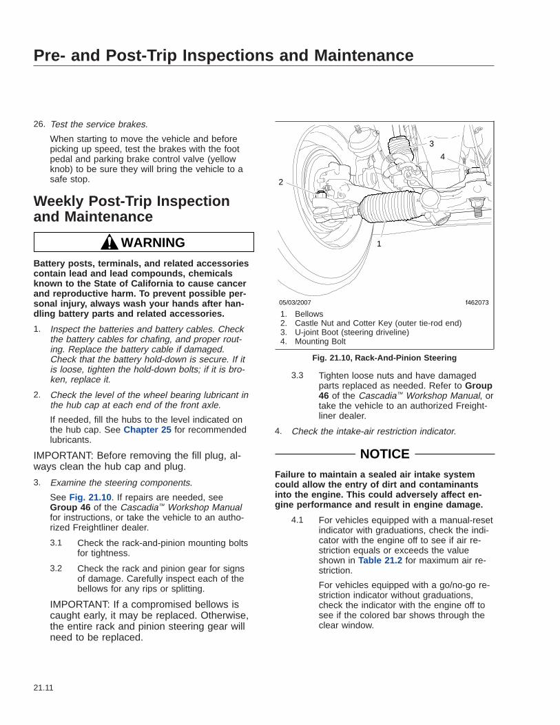
26. Test the service brakes.
When starting to move the vehicle and beforepicking up speed, test the brakes with the footpedal and parking brake control valve (yellowknob) to be sure they will bring the vehicle to asafe stop.
Weekly Post-Trip Inspectionand Maintenance
WARNINGBattery posts, terminals, and related accessoriescontain lead and lead compounds, chemicalsknown to the State of California to cause cancerand reproductive harm. To prevent possible per-sonal injury, always wash your hands after han-dling battery parts and related accessories.
1. Inspect the batteries and battery cables. Checkthe battery cables for chafing, and proper rout-ing. Replace the battery cable if damaged.Check that the battery hold-down is secure. If itis loose, tighten the hold-down bolts; if it is bro-ken, replace it.
2. Check the level of the wheel bearing lubricant inthe hub cap at each end of the front axle.
If needed, fill the hubs to the level indicated onthe hub cap. See Chapter 25 for recommendedlubricants.
IMPORTANT: Before removing the fill plug, al-ways clean the hub cap and plug.
3. Examine the steering components.
See Fig. 21.10 . If repairs are needed, seeGroup 46 of the Cascadia™ Workshop Manualfor instructions, or take the vehicle to an autho-rized Freightliner dealer.
3.1 Check the rack-and-pinion mounting boltsfor tightness.
3.2 Check the rack and pinion gear for signsof damage. Carefully inspect each of thebellows for any rips or splitting.
IMPORTANT: If a compromised bellows iscaught early, it may be replaced. Otherwise,the entire rack and pinion steering gear willneed to be replaced.
3.3 Tighten loose nuts and have damagedparts replaced as needed. Refer to Group46 of the Cascadia™ Workshop Manual, ortake the vehicle to an authorized Freight-liner dealer.
4. Check the intake-air restriction indicator.
NOTICEFailure to maintain a sealed air intake systemcould allow the entry of dirt and contaminantsinto the engine. This could adversely affect en-gine performance and result in engine damage.
4.1 For vehicles equipped with a manual-resetindicator with graduations, check the indi-cator with the engine off to see if air re-striction equals or exceeds the valueshown in Table 21.2 for maximum air re-striction.
For vehicles equipped with a go/no-go re-striction indicator without graduations,check the indicator with the engine off tosee if the colored bar shows through theclear window.
05/03/2007
1
2
3
4
f462073
1. Bellows2. Castle Nut and Cotter Key (outer tie-rod end)3. U-joint Boot (steering driveline)4. Mounting Bolt
Fig. 21.10, Rack-And-Pinion Steering
Pre- and Post-Trip Inspections and Maintenance
21.11
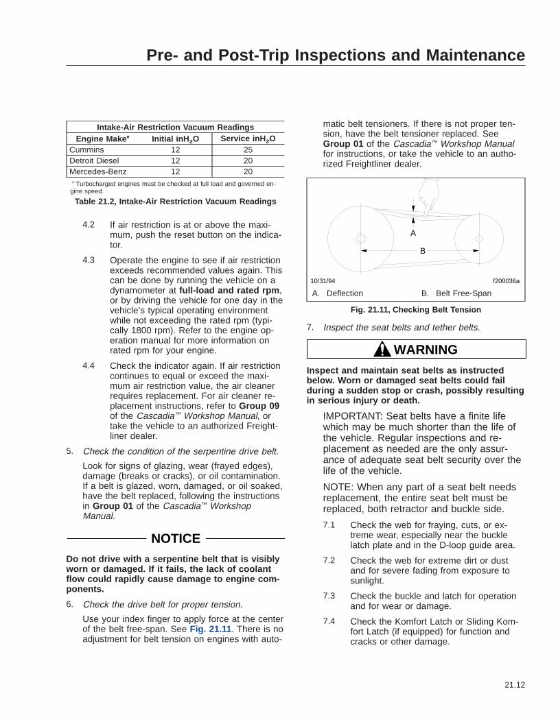
Intake-Air Restriction Vacuum ReadingsEngine Make * Initial inH 2O Service inH 2O
Cummins 12 25Detroit Diesel 12 20Mercedes-Benz 12 20* Turbocharged engines must be checked at full load and governed en-
gine speed.
Table 21.2, Intake-Air Restriction Vacuum Readings
4.2 If air restriction is at or above the maxi-mum, push the reset button on the indica-tor.
4.3 Operate the engine to see if air restrictionexceeds recommended values again. Thiscan be done by running the vehicle on adynamometer at full-load and rated rpm ,or by driving the vehicle for one day in thevehicle’s typical operating environmentwhile not exceeding the rated rpm (typi-cally 1800 rpm). Refer to the engine op-eration manual for more information onrated rpm for your engine.
4.4 Check the indicator again. If air restrictioncontinues to equal or exceed the maxi-mum air restriction value, the air cleanerrequires replacement. For air cleaner re-placement instructions, refer to Group 09of the Cascadia™ Workshop Manual, ortake the vehicle to an authorized Freight-liner dealer.
5. Check the condition of the serpentine drive belt.
Look for signs of glazing, wear (frayed edges),damage (breaks or cracks), or oil contamination.If a belt is glazed, worn, damaged, or oil soaked,have the belt replaced, following the instructionsin Group 01 of the Cascadia™ WorkshopManual.
NOTICEDo not drive with a serpentine belt that is visiblyworn or damaged. If it fails, the lack of coolantflow could rapidly cause damage to engine com-ponents.
6. Check the drive belt for proper tension.
Use your index finger to apply force at the centerof the belt free-span. See Fig. 21.11 . There is noadjustment for belt tension on engines with auto-
matic belt tensioners. If there is not proper ten-sion, have the belt tensioner replaced. SeeGroup 01 of the Cascadia™ Workshop Manualfor instructions, or take the vehicle to an autho-rized Freightliner dealer.
7. Inspect the seat belts and tether belts.
WARNINGInspect and maintain seat belts as instructedbelow. Worn or damaged seat belts could failduring a sudden stop or crash, possibly resultingin serious injury or death.
IMPORTANT: Seat belts have a finite lifewhich may be much shorter than the life ofthe vehicle. Regular inspections and re-placement as needed are the only assur-ance of adequate seat belt security over thelife of the vehicle.
NOTE: When any part of a seat belt needsreplacement, the entire seat belt must bereplaced, both retractor and buckle side.
7.1 Check the web for fraying, cuts, or ex-treme wear, especially near the bucklelatch plate and in the D-loop guide area.
7.2 Check the web for extreme dirt or dustand for severe fading from exposure tosunlight.
7.3 Check the buckle and latch for operationand for wear or damage.
7.4 Check the Komfort Latch or Sliding Kom-fort Latch (if equipped) for function andcracks or other damage.
10/31/94 f200036a
A
B
A. Deflection B. Belt Free-Span
Fig. 21.11, Checking Belt Tension
Pre- and Post-Trip Inspections and Maintenance
21.12
7.5 Check the upper seat belt mount on thedoor pillar for damage.
7.6 Check the web retractor for function anddamage.
7.7 Check the mounting bolts for tightnessand tighten any that are loose.
Monthly Post-Trip Inspectionand Maintenance
WARNINGBattery posts, terminals, and related accessoriescontain lead and lead compounds, chemicalsknown to the State of California to cause cancerand reproductive harm. To prevent possible per-sonal injury, always wash your hands after han-dling battery parts and related accessories.
1. Clean the batteries.
1.1 Remove any corrosion from the hold-downand the top of the battery.
NOTICETake care to keep the vent plugs tight so that theneutralizing solution does not enter any of thebattery cells and damage the battery.
1.2 Use a soda solution to neutralize the acidpresent, then rinse off the soda solutionwith clean water.
1.3 If the battery posts or cable terminals arecorroded, disconnect the terminals fromthe posts. Clean them with a soda solutionand a wire brush. After cleaning, connectthe terminals to the battery posts, thenapply a thin coat of dielectric grease to theposts and terminals to help retard corro-sion.
2. Inspect the radiator and heater hoses, includingthe clamps and support brackets.
2.1 Make sure the radiator inlet and outlethoses are pliable and are not cracking orballooning. Replace hoses that show signsof cracking, weakening, or ballooning.
2.2 Make sure the heater hoses are pliableand are not cracking or ballooning. Re-place hoses that show signs of cracking,weakening, or ballooning.
2.3 Tighten hose clamps as necessary, but donot overtighten, as hose life can be ad-versely affected.
2.4 Be sure the hose support brackets aresecurely fastened. Make sure the hosesare not located near sources of wear,abrasion, or high heat.
IMPORTANT: Replace all hoses, includingheater hoses, at the same time. Service-typeknitted or braided yarn-reinforced neoprenehose is acceptable. Silicone hoses having anextended service life can be substituted for thereinforced neoprene type. See the AllianceParts Catalog at www.alliancebrandparts.com ,or contact your Freightliner Dealer.
3. Check the steering wheel for excessive play.
3.1 With the front tires straight ahead, turn thesteering wheel until motion is observed atthe front wheels.
3.2 Align a reference mark on a ruler, thenslowly turn the steering wheel in the oppo-site direction until motion is again detectedat the wheels.
3.3 Measure the lash (free play) at the rim ofthe steering wheel. Excessive lash existsif steering wheel movement exceeds 2-1/4inches (57 mm) with an 18-inch (450-mm)steering wheel.
If there is excessive lash, check the steer-ing system for wear or incorrect adjust-ment of the linkage and steering gear be-fore operating the vehicle.
4. Check the brake lining wear on all vehicles, in-cluding those with automatic slack adjusters.Proper brake operation is dependent on periodicmaintenance and inspection of the brake linings.
4.1 Check that brake linings are free of oil andgrease.
4.2 Inspect the thickness of the brake linings.If the axle assembly is equipped with adust shield or backing plate, remove theinspection plugs. If any brake linings are
Pre- and Post-Trip Inspections and Maintenance
21.13
worn to less than approximately 1/4 inch(6.4 mm) at the thinnest point, have thelinings replaced on all brake assemblieson that axle. See Group 42 of the Casca-dia™ Workshop Manual for lining replace-ment instructions and camshaft end-playinspection.
4.3 Check the brake drums for wear andcracks.
4.4 Check that the inspection plugs in the dustshields or backing plates, if so equipped,are installed.
Pre- and Post-Trip Inspections and Maintenance
21.14
22
Cab AppearanceCab Washing and Polishing . . . . . . . . . . . . . . . . . . . . . . . . . . . . . . . . . . . . . . . . . . . . . . . . . . . . . . . . 22.1Care of Fiberglass Parts . . . . . . . . . . . . . . . . . . . . . . . . . . . . . . . . . . . . . . . . . . . . . . . . . . . . . . . . . . 22.1Care of Chrome Parts . . . . . . . . . . . . . . . . . . . . . . . . . . . . . . . . . . . . . . . . . . . . . . . . . . . . . . . . . . . . 22.1Care of Exterior Lights . . . . . . . . . . . . . . . . . . . . . . . . . . . . . . . . . . . . . . . . . . . . . . . . . . . . . . . . . . . . 22.1Dashboard Care . . . . . . . . . . . . . . . . . . . . . . . . . . . . . . . . . . . . . . . . . . . . . . . . . . . . . . . . . . . . . . . . . 22.1Vinyl Upholstery Cleaning . . . . . . . . . . . . . . . . . . . . . . . . . . . . . . . . . . . . . . . . . . . . . . . . . . . . . . . . . 22.2Velour Upholstery Cleaning . . . . . . . . . . . . . . . . . . . . . . . . . . . . . . . . . . . . . . . . . . . . . . . . . . . . . . . . 22.2
Cab Washing and PolishingIMPORTANT: Carefully read all instructions be-fore using or applying any cleaner or product onthe vehicle or components. Failure to followmanufacturers’ recommendations can result indamage to the finish.
To protect the finish of your new vehicle, follow theseguidelines carefully.
• During the first 30 days, rinse your vehicle fre-quently with water. If the vehicle is dirty, use amild liquid soap. Do not use detergent.
• During the first 30 days, do not use anythingabrasive on your vehicle. Brushes, chemicals,and cleaners may scratch the finish.
• During the first 120 days, do not wax yourvehicle.
To extend the life of your vehicle’s finish, follow theseguidelines.
• Avoid washing your vehicle in the hot sun.
• Always use water. After the cab is completelywashed, dry it with a towel or chamois.
• Do not dust painted surfaces with a dry cloth,as this will scratch the paint.
• Do not remove ice or snow from a painted sur-face with a scraper of any sort.
• To prevent damage to the finish, wax it regu-larly. Before waxing, if the finish has becomedull, remove oxidized paint using a cleanerspecifically designed for this purpose. Removeall road tar and tree sap before waxing.Freightliner recommends that a quality brand ofcleaner or cleaner-polish and polishing wax beused.
• Do not let diesel fuel or antifreeze stand on apainted surface. If either should occur, rinsethe surface off with water.
• To prevent rust, have any nicks or other dam-age on the finish touched up as soon as pos-sible.
• Park your vehicle in a sheltered area wheneverpossible.
Care of Fiberglass PartsWash unpainted fiberglass air fairings and shieldsmonthly with a mild detergent, such as dishwashingliquid. Avoid strong alkaline cleansers.
Apply a wax specifically designed for fiberglass.
Care of Chrome PartsTo prevent rust, keep chrome parts clean and pro-tected at all times. This is especially important duringwinter driving and in coastal areas where there isexposure to salt air.
When cleaning chrome parts, use clean water and asoft cloth or sponge. A mild detergent may also beused.
Sponge gently, then rinse. If necessary, use a non-abrasive chrome cleaner to remove stubborn rust orother material. Do not use steel wool.
To help protect the chrome after cleaning, apply acoat of polishing wax to the surface. Never use waxon parts that are exposed to high heat, such as ex-haust pipes.
Care of Exterior LightsClean the headlight lenses by hand only, using aflannel cloth with mild, non-caustic soap or detergent,and water.
CAUTIONDo not use a power buffer, paper towels, chemi-cal solvents, or abrasive cleaners on the head-light lens, all of which can remove the UV coatingfrom the surface, and result in yellowing of thelens.
Dashboard CarePeriodically wipe the dashboard with a water-dampened cloth. A mild detergent can be used, butavoid using strong detergents.
CAUTIONDo not use Armor-All Protectant ®, STP Son-of-a-Gun®, or other equivalent treatments. Thesecleaners contain vinyl plasticizers that can cause
Cab Appearance
22.1
stress crazing in the interior plastic panels,which can result in cracking of the panels.
Vinyl Upholstery CleaningTo prevent soiling, frequent vacuuming or light brush-ing to remove dust and dirt is recommended. Harshcleaning agents can cause permanent damage tovinyl upholstery. To preserve the upholstery and pre-vent damage, carefully review the following sectionsfor recommended cleaning procedures. Waxing orrefinishing improves soil resistance and cleanabilityfor all vinyls. Any hard wax, such as that used onautomobiles, may be used.
Ordinary DirtWash the upholstery with warm water and mild soap,such as saddle or oil soap. Apply soapy water to alarge area and allow to soak for a few minutes, thenrub briskly with a cloth to remove the dirt. This canbe repeated several times, as necessary.
If dirt is deeply imbedded, use a soft bristle brushafter applying the soap.
If dirt is extremely difficult to remove, wall-washingpreparations normally found around the home can beused. Powdered cleaners, such as those used forsinks and tiles, are abrasive and must be used withcaution as they can scratch the vinyl or give it a per-manent dull appearance.
Chewing GumHarden the gum with an ice cube wrapped in a plas-tic bag, then scrape it off with a dull knife. Any re-maining traces of gum can be removed with an all-purpose light oil (peanut butter will also work) andwiped off.
Tars, Asphalts, and CreosoteEach of these items stains vinyl after prolonged con-tact. They should be wiped off immediately and thearea carefully cleaned, using a cloth dampened withnaphtha.
Paint, Shoe Heel MarksPaint should be removed immediately. Do not usepaint remover or liquid-type brush cleaner on vinyl.An unprinted cloth, dampened with naphtha or tur-
pentine may be used. Use care to prevent contactwith parts of the upholstery that are not vinyl.
Sulfide StainsSulfide compounds, such as those found in eggs andsome canned goods, can stain after prolonged con-tact with vinyl. These stains can be removed by plac-ing a clean, unprinted piece of cloth over the spottedarea and pouring a liberal amount of 6 percent hy-drogen peroxide onto the cloth. Allow the saturatedcloth to remain on the spot for 30 to 60 minutes. Forstubborn spots, allow the hydrogen-peroxide satu-rated cloth to remain on the area overnight. Use cau-tion to prevent the solution from seeping into theseams, or it will weaken the cotton thread.
Nail Polish and Nail Polish RemoverProlonged contact with these substances causes per-manent damage to vinyl. Careful blotting immediatelyafter contact minimizes damage. Do not spread theliquid during removal.
Shoe PolishMost shoe polishes contain dyes which penetratevinyl and stain it permanently. Shoe polish should bewiped off as quickly as possible using naphtha orlighter fluid. If staining occurs, try the procedure usedfor sulfide stains.
Ball Point InkBall point ink can sometimes be removed if rubbedimmediately with a damp cloth, using water or rub-bing alcohol. If this does not work, try the procedureused for sulfide stains.
MiscellaneousIf stains do not respond to any of the treatments de-scribed above, it is sometimes helpful to expose thevinyl to direct sunlight for up to 30 hours. Mustard,ball point ink, certain shoe polishes, and dyes oftenbleach out in direct sunlight, leaving the vinyl undam-aged.
Velour Upholstery CleaningTo prevent soiling, frequent vacuuming or light brush-ing to remove dust and dirt is recommended. Spotclean with a mild solvent or an upholstery shampoo,
Cab Appearance
22.2
or the foam from a mild detergent. When using a sol-vent or a dry-cleaning product, follow the instructionscarefully, and clean only in a well-ventilated area.Avoid any product that contains carbon tetrachlorideor other toxic materials. With either method, pretest asmall area before proceeding. Use a professionalupholstery cleaning service when extensive cleaningis needed.
Grease and Oil-Based StainsDampen a small absorbent cloth with dry-cleaningsolvent or spot remover. Apply the cloth carefully tothe spot from the outer edge to the center. Pat andblot the spot with a clean, dry cloth. Repeat severaltimes, as necessary, turning the cloths so that thestain does not redeposit on the fabric.
Sugar and Water-Based StainsApply water-based detergent or cleaner, working incircular motions. Pat and blot as dry as possible. Re-peat, if necessary, before drying thoroughly.
Chewing Gum or WaxHarden the gum or wax with an ice cube wrapped ina plastic bag, then scrape it off with a dull knife. Ex-cess wax can be absorbed by placing a thick whiteblotter over the wax and heating with a warm (nothot) iron. Remove the remainder by using the proce-dure for grease and oil-based stains.
MildewBrush the dry fabric with a soft brush. Sponge withdetergent, and blot. If the fabric is colorfast, dilute ateaspoon of bleach in one quart (one liter) of coolwater. Apply with a swab, directly on the mildewstain. Dab repeatedly with clear, cool water, and blotdry.
Cab Appearance
22.3
23
Headlight AimingPreliminary Checks . . . . . . . . . . . . . . . . . . . . . . . . . . . . . . . . . . . . . . . . . . . . . . . . . . . . . . . . . . . . . . . 23.1Checking Headlight Aim . . . . . . . . . . . . . . . . . . . . . . . . . . . . . . . . . . . . . . . . . . . . . . . . . . . . . . . . . . . 23.1Adjusting Headlight Aim . . . . . . . . . . . . . . . . . . . . . . . . . . . . . . . . . . . . . . . . . . . . . . . . . . . . . . . . . . . 23.2
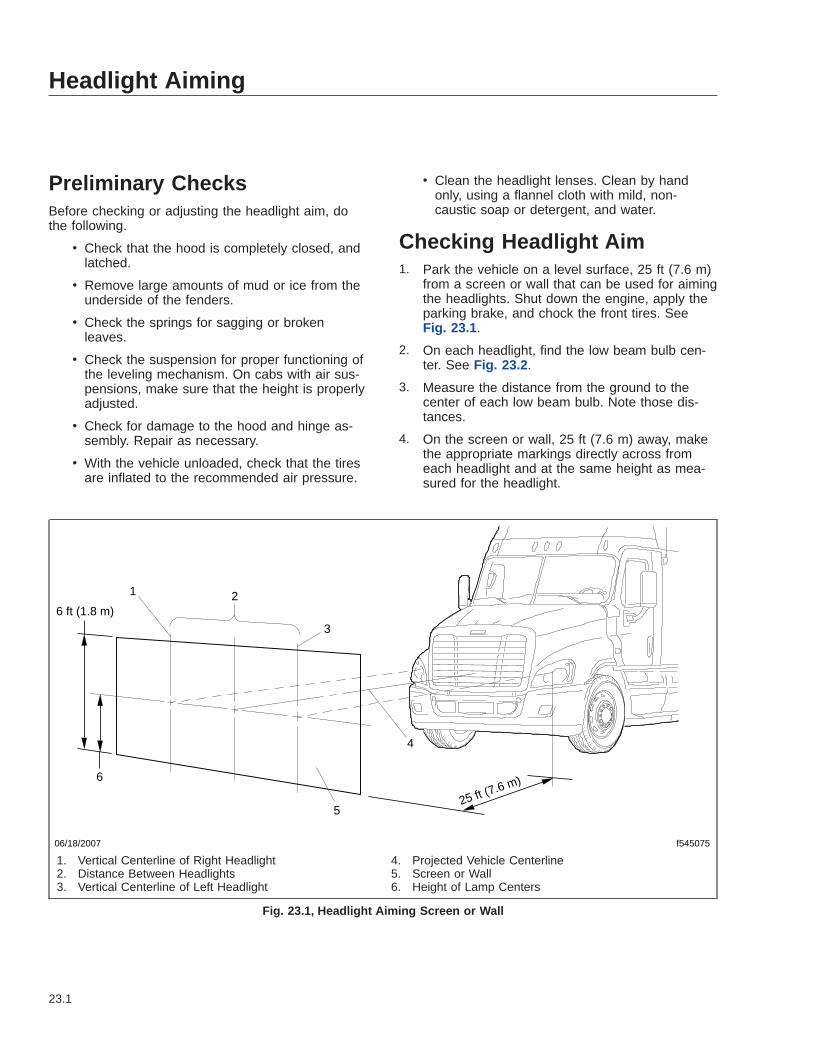
Preliminary ChecksBefore checking or adjusting the headlight aim, dothe following.
• Check that the hood is completely closed, andlatched.
• Remove large amounts of mud or ice from theunderside of the fenders.
• Check the springs for sagging or brokenleaves.
• Check the suspension for proper functioning ofthe leveling mechanism. On cabs with air sus-pensions, make sure that the height is properlyadjusted.
• Check for damage to the hood and hinge as-sembly. Repair as necessary.
• With the vehicle unloaded, check that the tiresare inflated to the recommended air pressure.
• Clean the headlight lenses. Clean by handonly, using a flannel cloth with mild, non-caustic soap or detergent, and water.
Checking Headlight Aim1. Park the vehicle on a level surface, 25 ft (7.6 m)
from a screen or wall that can be used for aimingthe headlights. Shut down the engine, apply theparking brake, and chock the front tires. SeeFig. 23.1 .
2. On each headlight, find the low beam bulb cen-ter. See Fig. 23.2 .
3. Measure the distance from the ground to thecenter of each low beam bulb. Note those dis-tances.
4. On the screen or wall, 25 ft (7.6 m) away, makethe appropriate markings directly across fromeach headlight and at the same height as mea-sured for the headlight.
f545075
6 ft (1.8 m)
06/18/2007
1 2
3
4
5
6
25 ft (7.6 m)
1. Vertical Centerline of Right Headlight2. Distance Between Headlights3. Vertical Centerline of Left Headlight
4. Projected Vehicle Centerline5. Screen or Wall6. Height of Lamp Centers
Fig. 23.1, Headlight Aiming Screen or Wall
Headlight Aiming
23.1
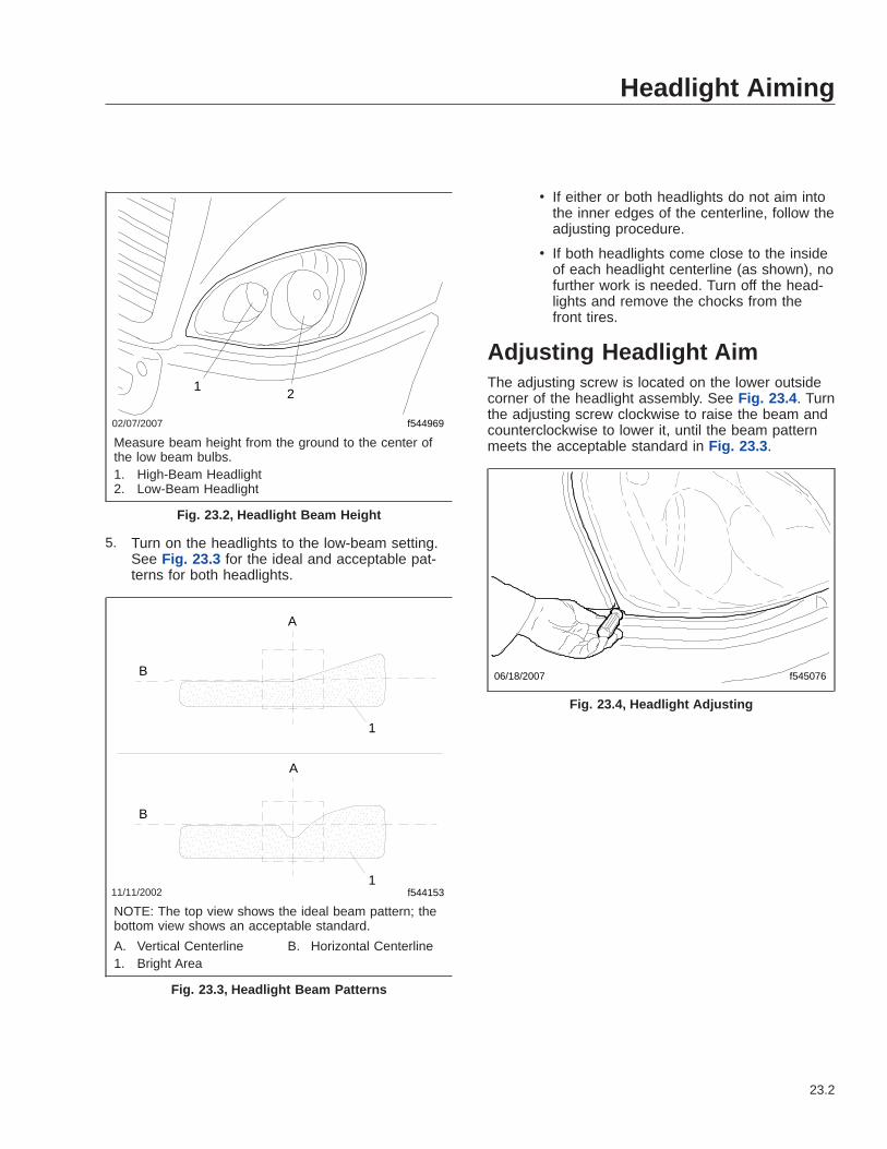
5. Turn on the headlights to the low-beam setting.See Fig. 23.3 for the ideal and acceptable pat-terns for both headlights.
• If either or both headlights do not aim intothe inner edges of the centerline, follow theadjusting procedure.
• If both headlights come close to the insideof each headlight centerline (as shown), nofurther work is needed. Turn off the head-lights and remove the chocks from thefront tires.
Adjusting Headlight AimThe adjusting screw is located on the lower outsidecorner of the headlight assembly. See Fig. 23.4 . Turnthe adjusting screw clockwise to raise the beam andcounterclockwise to lower it, until the beam patternmeets the acceptable standard in Fig. 23.3 .
02/07/2007 f544969
12
Measure beam height from the ground to the center ofthe low beam bulbs.1. High-Beam Headlight2. Low-Beam Headlight
Fig. 23.2, Headlight Beam Height
11/11/2002
1
1f544153
A
A
B
B
NOTE: The top view shows the ideal beam pattern; thebottom view shows an acceptable standard.
A. Vertical Centerline B. Horizontal Centerline1. Bright Area
Fig. 23.3, Headlight Beam Patterns
06/18/2007 f545076
Fig. 23.4, Headlight Adjusting
Headlight Aiming
23.2
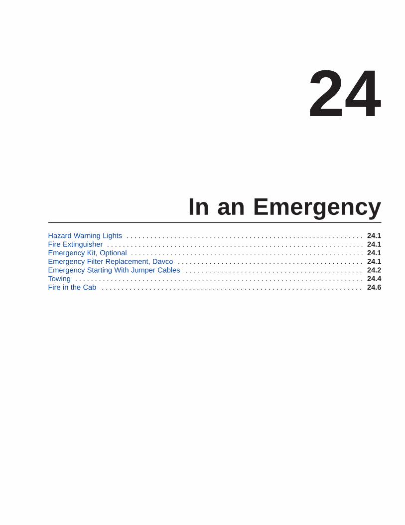
24
In an EmergencyHazard Warning Lights . . . . . . . . . . . . . . . . . . . . . . . . . . . . . . . . . . . . . . . . . . . . . . . . . . . . . . . . . . . . 24.1Fire Extinguisher . . . . . . . . . . . . . . . . . . . . . . . . . . . . . . . . . . . . . . . . . . . . . . . . . . . . . . . . . . . . . . . . . 24.1Emergency Kit, Optional . . . . . . . . . . . . . . . . . . . . . . . . . . . . . . . . . . . . . . . . . . . . . . . . . . . . . . . . . . . 24.1Emergency Filter Replacement, Davco . . . . . . . . . . . . . . . . . . . . . . . . . . . . . . . . . . . . . . . . . . . . . . . 24.1Emergency Starting With Jumper Cables . . . . . . . . . . . . . . . . . . . . . . . . . . . . . . . . . . . . . . . . . . . . . 24.2Towing . . . . . . . . . . . . . . . . . . . . . . . . . . . . . . . . . . . . . . . . . . . . . . . . . . . . . . . . . . . . . . . . . . . . . . . . . 24.4Fire in the Cab . . . . . . . . . . . . . . . . . . . . . . . . . . . . . . . . . . . . . . . . . . . . . . . . . . . . . . . . . . . . . . . . . . 24.6
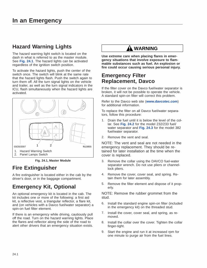
Hazard Warning LightsThe hazard warning light switch is located on thedash in what is referred to as the master module.See Fig. 24.1 . The hazard lights can be activatedregardless of the ignition switch position.
To activate the hazard lights, push the center of theswitch once. The switch will blink at the same ratethat the hazard lights flash. Push the switch again toturn them off. All the turn signal lights on the vehicleand trailer, as well as the turn signal indicators in theICU, flash simultaneously when the hazard lights areactivated.
Fire ExtinguisherA fire extinguisher is located either in the cab by thedriver’s door, or in the baggage compartment.
Emergency Kit, OptionalAn optional emergency kit is located in the cab. Thekit includes one or more of the following: a first aidkit, a reflective vest, a triangular reflector, a flare kit,and (on vehicles with a Davco fuel/water separator) aspin-on fuel filter element.
If there is an emergency while driving, cautiously pulloff the road. Turn on the hazard warning lights. Placethe flares and reflector along the side of the road toalert other drivers that an emergency situation exists.
WARNINGUse extreme care when placing flares in emer-gency situations that involve exposure to flam-mable substances such as fuel. An explosion orfire could occur causing serious personal injury.
Emergency FilterReplacement, DavcoIf the filter cover on the Davco fuel/water separator isbroken, it will not be possible to operate the vehicle.A standard spin-on filter will correct this problem.
Refer to the Davco web site (www.davcotec.com )for additional information.
To replace the filter on all Davco fuel/water separa-tors, follow this procedure:
1. Drain the fuel until it is below the level of the col-lar. See Fig. 24.2 for the model 232/233 fuel/water separator and Fig. 24.3 for the model 382fuel/water separator.
2. Remove the vent and seal.
NOTE: The vent and seal are not needed in theemergency replacement. They should be re-tained for later installation at the time when thecover is replaced.
3. Remove the collar using the DAVCO fuel-waterseparator wrench. Do not use pliers or channel-lock pliers.
4. Remove the cover, cover seal, and spring. Re-tain them for later assembly.
5. Remove the filter element and dispose of it prop-erly.
NOTE: Remove the rubber grommet from thestud.
6. Install the standard engine spin-on filter (includedin the emergency kit) on the threaded stud.
7. Install the cover, cover seal, and spring, as re-moved.
8. Install the collar over the cover. Tighten the collarfinger-tight.
9. Start the engine and run it at increased rpm forone minute to purge air from the fuel lines.
03/20/2007 1 f6108552
1. Hazard Warning Switch2. Panel Lamps Switch
Fig. 24.1, Master Module
In an Emergency
24.1
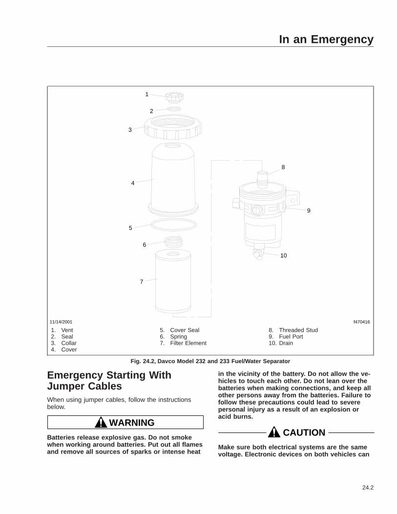
Emergency Starting WithJumper CablesWhen using jumper cables, follow the instructionsbelow.
WARNINGBatteries release explosive gas. Do not smokewhen working around batteries. Put out all flamesand remove all sources of sparks or intense heat
in the vicinity of the battery. Do not allow the ve-hicles to touch each other. Do not lean over thebatteries when making connections, and keep allother persons away from the batteries. Failure tofollow these precautions could lead to severepersonal injury as a result of an explosion oracid burns.
CAUTIONMake sure both electrical systems are the samevoltage. Electronic devices on both vehicles can
f47041611/14/2001
1
2
3
4
5
6
7
8
10
9
1. Vent2. Seal3. Collar4. Cover
5. Cover Seal6. Spring7. Filter Element
8. Threaded Stud9. Fuel Port10. Drain
Fig. 24.2, Davco Model 232 and 233 Fuel/Water Separator
In an Emergency
24.2
be damaged when connected to a vehicle with adifferent operating voltage.
NOTE: On vehicles equipped with optional un-derhood jump start posts, connect to theseposts instead of the batteries.
1. Apply the parking brakes and turn off the lightsand all other electrical devices.
2. Remove the battery box cover by pulling on theend of each hold-down latch until the end clearsthe catch, then pivoting the latches out of theway, and lifting off the cover. See Fig. 24.4 .
CAUTIONAlways connect the battery, jumper cables, andcharger correctly (positive-to-positive andnegative-to-negative). Connecting a charging de-vice backwards (positive-to-negative) can se-verely damage the vehicle electrical content andcause non-warrantable failures.
3. Connect the positive (+) jumper cable to thepositive battery post on the Cascadia needingthe jump start, then connect the other end of thepositive jumper cable to the positive battery or
f470417
1
2
4
6
7
5
8
11/14/2001
3
9
11
10
1. Collar2. Vent3. Seal4. Cover
5. Cover Seal6. Spring7. Filter Element8. Threaded Stud
9. Fuel Port10. Drain11. Bottom-Plate Collar
Fig. 24.3, Davco Model 382 Fuel/Water Separator
In an Emergency
24.3
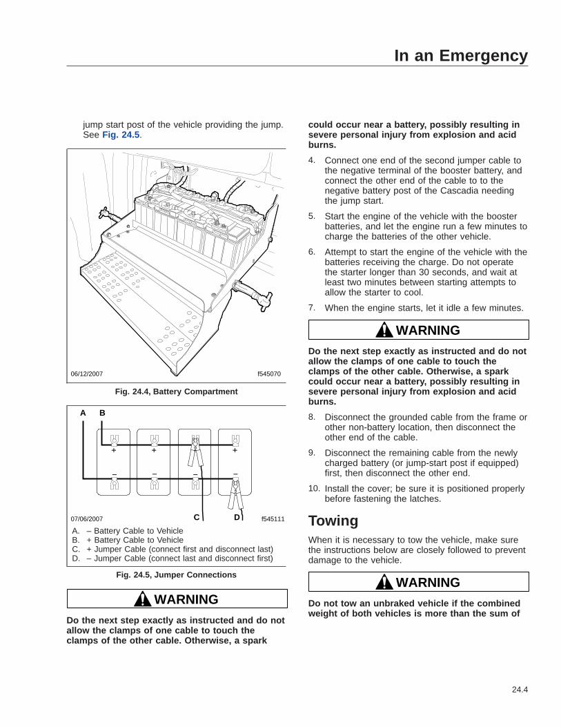
jump start post of the vehicle providing the jump.See Fig. 24.5 .
WARNINGDo the next step exactly as instructed and do notallow the clamps of one cable to touch theclamps of the other cable. Otherwise, a spark
could occur near a battery, possibly resulting insevere personal injury from explosion and acidburns.
4. Connect one end of the second jumper cable tothe negative terminal of the booster battery, andconnect the other end of the cable to to thenegative battery post of the Cascadia needingthe jump start.
5. Start the engine of the vehicle with the boosterbatteries, and let the engine run a few minutes tocharge the batteries of the other vehicle.
6. Attempt to start the engine of the vehicle with thebatteries receiving the charge. Do not operatethe starter longer than 30 seconds, and wait atleast two minutes between starting attempts toallow the starter to cool.
7. When the engine starts, let it idle a few minutes.
WARNINGDo the next step exactly as instructed and do notallow the clamps of one cable to touch theclamps of the other cable. Otherwise, a sparkcould occur near a battery, possibly resulting insevere personal injury from explosion and acidburns.
8. Disconnect the grounded cable from the frame orother non-battery location, then disconnect theother end of the cable.
9. Disconnect the remaining cable from the newlycharged battery (or jump-start post if equipped)first, then disconnect the other end.
10. Install the cover; be sure it is positioned properlybefore fastening the latches.
TowingWhen it is necessary to tow the vehicle, make surethe instructions below are closely followed to preventdamage to the vehicle.
WARNINGDo not tow an unbraked vehicle if the combinedweight of both vehicles is more than the sum of
06/12/2007 f545070
Fig. 24.4, Battery Compartment
+
−
+
−
f54511107/06/2007
+
−
+
−
A B
C D
A. – Battery Cable to VehicleB. + Battery Cable to VehicleC. + Jumper Cable (connect first and disconnect last)D. – Jumper Cable (connect last and disconnect first)
Fig. 24.5, Jumper Connections
In an Emergency
24.4
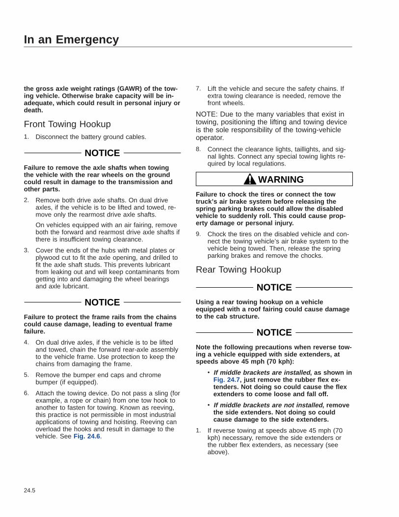
the gross axle weight ratings (GAWR) of the tow-ing vehicle. Otherwise brake capacity will be in-adequate, which could result in personal injury ordeath.
Front Towing Hookup1. Disconnect the battery ground cables.
NOTICEFailure to remove the axle shafts when towingthe vehicle with the rear wheels on the groundcould result in damage to the transmission andother parts.
2. Remove both drive axle shafts. On dual driveaxles, if the vehicle is to be lifted and towed, re-move only the rearmost drive axle shafts.
On vehicles equipped with an air fairing, removeboth the forward and rearmost drive axle shafts ifthere is insufficient towing clearance.
3. Cover the ends of the hubs with metal plates orplywood cut to fit the axle opening, and drilled tofit the axle shaft studs. This prevents lubricantfrom leaking out and will keep contaminants fromgetting into and damaging the wheel bearingsand axle lubricant.
NOTICEFailure to protect the frame rails from the chainscould cause damage, leading to eventual framefailure.
4. On dual drive axles, if the vehicle is to be liftedand towed, chain the forward rear-axle assemblyto the vehicle frame. Use protection to keep thechains from damaging the frame.
5. Remove the bumper end caps and chromebumper (if equipped).
6. Attach the towing device. Do not pass a sling (forexample, a rope or chain) from one tow hook toanother to fasten for towing. Known as reeving,this practice is not permissible in most industrialapplications of towing and hoisting. Reeving canoverload the hooks and result in damage to thevehicle. See Fig. 24.6 .
7. Lift the vehicle and secure the safety chains. Ifextra towing clearance is needed, remove thefront wheels.
NOTE: Due to the many variables that exist intowing, positioning the lifting and towing deviceis the sole responsibility of the towing-vehicleoperator.
8. Connect the clearance lights, taillights, and sig-nal lights. Connect any special towing lights re-quired by local regulations.
WARNINGFailure to chock the tires or connect the towtruck’s air brake system before releasing thespring parking brakes could allow the disabledvehicle to suddenly roll. This could cause prop-erty damage or personal injury.
9. Chock the tires on the disabled vehicle and con-nect the towing vehicle’s air brake system to thevehicle being towed. Then, release the springparking brakes and remove the chocks.
Rear Towing Hookup
NOTICEUsing a rear towing hookup on a vehicleequipped with a roof fairing could cause damageto the cab structure.
NOTICENote the following precautions when reverse tow-ing a vehicle equipped with side extenders, atspeeds above 45 mph (70 kph):
• If middle brackets are installed , as shown inFig. 24.7, just remove the rubber flex ex-tenders. Not doing so could cause the flexextenders to come loose and fall off.
• If middle brackets are not installed , removethe side extenders. Not doing so couldcause damage to the side extenders.
1. If reverse towing at speeds above 45 mph (70kph) necessary, remove the side extenders orthe rubber flex extenders, as necessary (seeabove).
In an Emergency
24.5
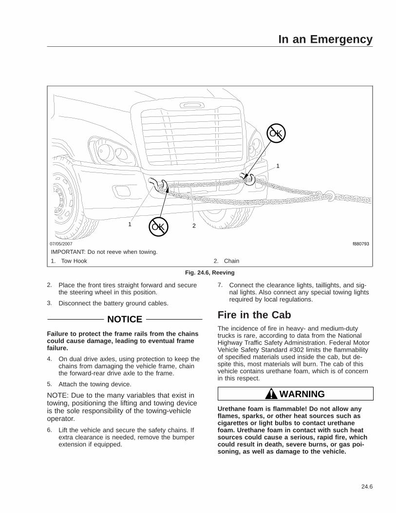
2. Place the front tires straight forward and securethe steering wheel in this position.
3. Disconnect the battery ground cables.
NOTICEFailure to protect the frame rails from the chainscould cause damage, leading to eventual framefailure.
4. On dual drive axles, using protection to keep thechains from damaging the vehicle frame, chainthe forward-rear drive axle to the frame.
5. Attach the towing device.
NOTE: Due to the many variables that exist intowing, positioning the lifting and towing deviceis the sole responsibility of the towing-vehicleoperator.
6. Lift the vehicle and secure the safety chains. Ifextra clearance is needed, remove the bumperextension if equipped.
7. Connect the clearance lights, taillights, and sig-nal lights. Also connect any special towing lightsrequired by local regulations.
Fire in the CabThe incidence of fire in heavy- and medium-dutytrucks is rare, according to data from the NationalHighway Traffic Safety Administration. Federal MotorVehicle Safety Standard #302 limits the flammabilityof specified materials used inside the cab, but de-spite this, most materials will burn. The cab of thisvehicle contains urethane foam, which is of concernin this respect.
WARNINGUrethane foam is flammable! Do not allow anyflames, sparks, or other heat sources such ascigarettes or light bulbs to contact urethanefoam. Urethane foam in contact with such heatsources could cause a serious, rapid fire, whichcould result in death, severe burns, or gas poi-soning, as well as damage to the vehicle.
07/05/2007
OK
OK
1
1
2
f880793
IMPORTANT: Do not reeve when towing.
1. Tow Hook 2. Chain
Fig. 24.6, Reeving
In an Emergency
24.6
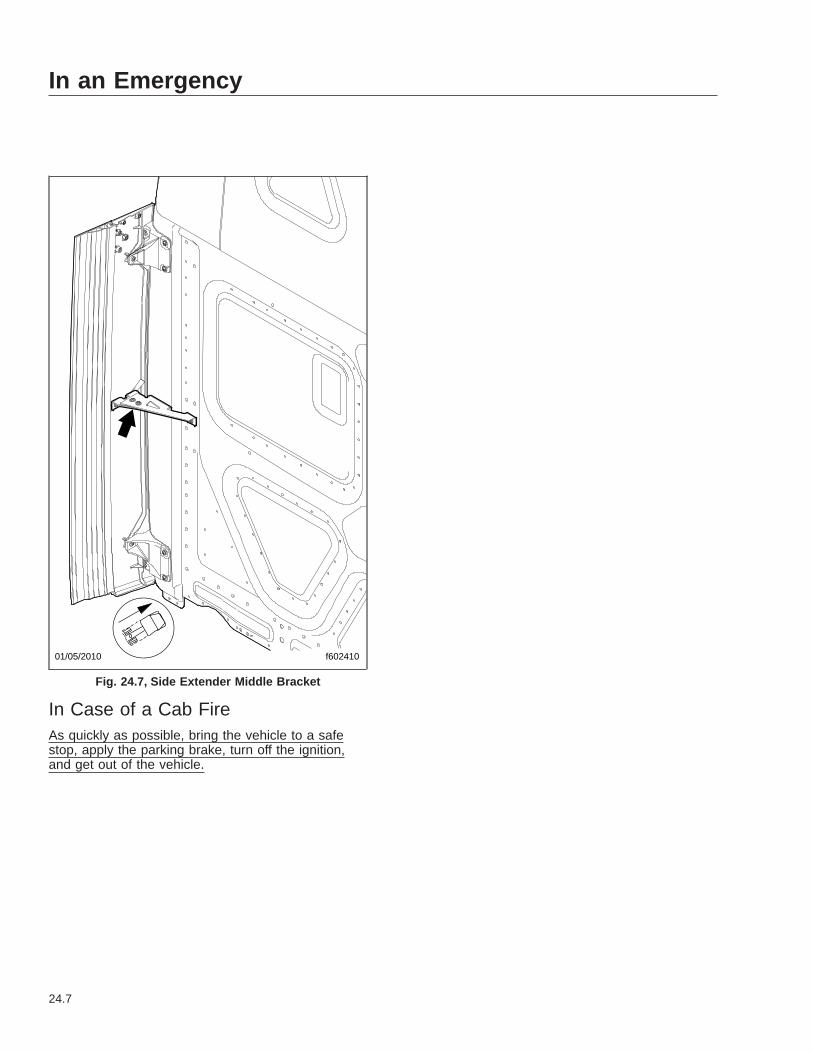
In Case of a Cab FireAs quickly as possible, bring the vehicle to a safestop, apply the parking brake, turn off the ignition,and get out of the vehicle.
01/05/2010 f602410
Fig. 24.7, Side Extender Middle Bracket
In an Emergency
24.7
25
SpecificationsFuses and Relays . . . . . . . . . . . . . . . . . . . . . . . . . . . . . . . . . . . . . . . . . . . . . . . . . . . . . . . . . . . . . . . . 25.1Replacement Bulbs . . . . . . . . . . . . . . . . . . . . . . . . . . . . . . . . . . . . . . . . . . . . . . . . . . . . . . . . . . . . . . 25.2Fluids and Lubricants . . . . . . . . . . . . . . . . . . . . . . . . . . . . . . . . . . . . . . . . . . . . . . . . . . . . . . . . . . . . . 25.3
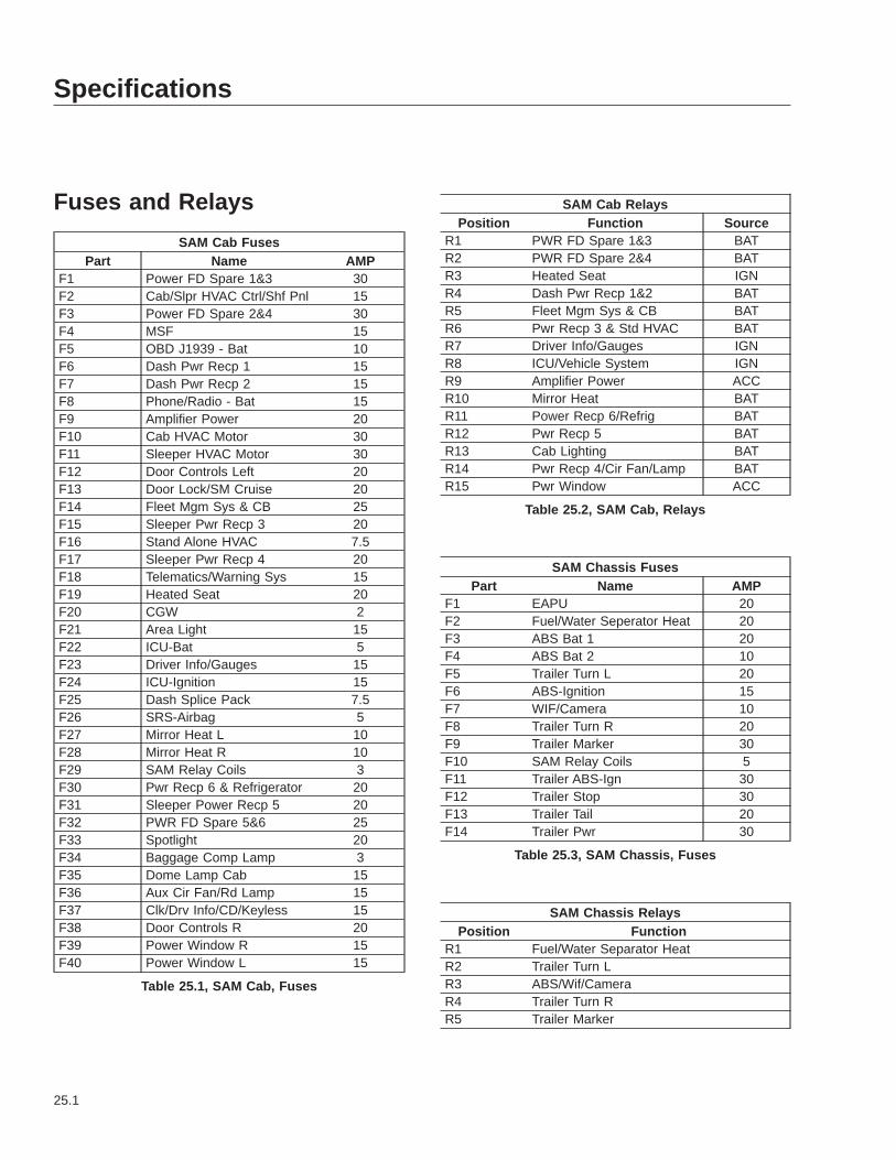
Fuses and Relays
SAM Cab FusesPart Name AMP
F1 Power FD Spare 1&3 30F2 Cab/Slpr HVAC Ctrl/Shf Pnl 15F3 Power FD Spare 2&4 30F4 MSF 15F5 OBD J1939 - Bat 10F6 Dash Pwr Recp 1 15F7 Dash Pwr Recp 2 15F8 Phone/Radio - Bat 15F9 Amplifier Power 20F10 Cab HVAC Motor 30F11 Sleeper HVAC Motor 30F12 Door Controls Left 20F13 Door Lock/SM Cruise 20F14 Fleet Mgm Sys & CB 25F15 Sleeper Pwr Recp 3 20F16 Stand Alone HVAC 7.5F17 Sleeper Pwr Recp 4 20F18 Telematics/Warning Sys 15F19 Heated Seat 20F20 CGW 2F21 Area Light 15F22 ICU-Bat 5F23 Driver Info/Gauges 15F24 ICU-Ignition 15F25 Dash Splice Pack 7.5F26 SRS-Airbag 5F27 Mirror Heat L 10F28 Mirror Heat R 10F29 SAM Relay Coils 3F30 Pwr Recp 6 & Refrigerator 20F31 Sleeper Power Recp 5 20F32 PWR FD Spare 5&6 25F33 Spotlight 20F34 Baggage Comp Lamp 3F35 Dome Lamp Cab 15F36 Aux Cir Fan/Rd Lamp 15F37 Clk/Drv Info/CD/Keyless 15F38 Door Controls R 20F39 Power Window R 15F40 Power Window L 15
Table 25.1, SAM Cab, Fuses
SAM Cab RelaysPosition Function Source
R1 PWR FD Spare 1&3 BATR2 PWR FD Spare 2&4 BATR3 Heated Seat IGNR4 Dash Pwr Recp 1&2 BATR5 Fleet Mgm Sys & CB BATR6 Pwr Recp 3 & Std HVAC BATR7 Driver Info/Gauges IGNR8 ICU/Vehicle System IGNR9 Amplifier Power ACCR10 Mirror Heat BATR11 Power Recp 6/Refrig BATR12 Pwr Recp 5 BATR13 Cab Lighting BATR14 Pwr Recp 4/Cir Fan/Lamp BATR15 Pwr Window ACC
Table 25.2, SAM Cab, Relays
SAM Chassis FusesPart Name AMP
F1 EAPU 20F2 Fuel/Water Seperator Heat 20F3 ABS Bat 1 20F4 ABS Bat 2 10F5 Trailer Turn L 20F6 ABS-Ignition 15F7 WIF/Camera 10F8 Trailer Turn R 20F9 Trailer Marker 30F10 SAM Relay Coils 5F11 Trailer ABS-Ign 30F12 Trailer Stop 30F13 Trailer Tail 20F14 Trailer Pwr 30
Table 25.3, SAM Chassis, Fuses
SAM Chassis RelaysPosition Function
R1 Fuel/Water Separator HeatR2 Trailer Turn LR3 ABS/Wif/CameraR4 Trailer Turn RR5 Trailer Marker
Specifications
25.1
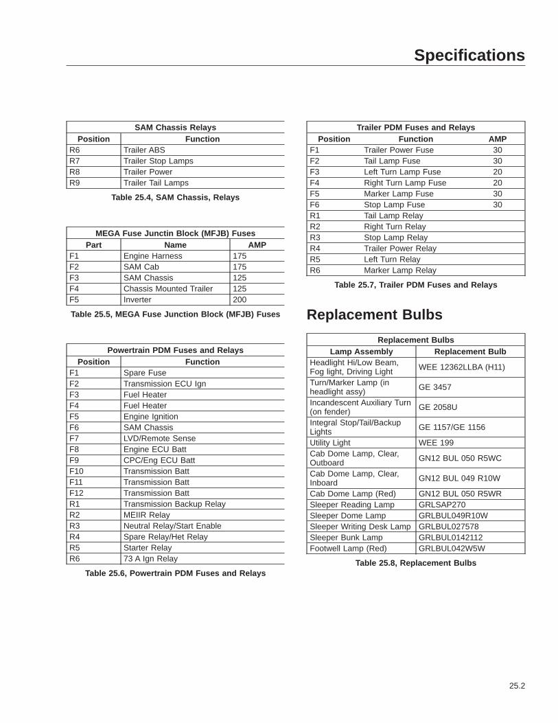
SAM Chassis RelaysPosition Function
R6 Trailer ABSR7 Trailer Stop LampsR8 Trailer PowerR9 Trailer Tail Lamps
Table 25.4, SAM Chassis, Relays
MEGA Fuse Junctin Block (MFJB) FusesPart Name AMP
F1 Engine Harness 175F2 SAM Cab 175F3 SAM Chassis 125F4 Chassis Mounted Trailer 125F5 Inverter 200
Table 25.5, MEGA Fuse Junction Block (MFJB) Fuses
Powertrain PDM Fuses and RelaysPosition Function
F1 Spare FuseF2 Transmission ECU IgnF3 Fuel HeaterF4 Fuel HeaterF5 Engine IgnitionF6 SAM ChassisF7 LVD/Remote SenseF8 Engine ECU BattF9 CPC/Eng ECU BattF10 Transmission BattF11 Transmission BattF12 Transmission BattR1 Transmission Backup RelayR2 MEIIR RelayR3 Neutral Relay/Start EnableR4 Spare Relay/Het RelayR5 Starter RelayR6 73 A Ign Relay
Table 25.6, Powertrain PDM Fuses and Relays
Trailer PDM Fuses and RelaysPosition Function AMP
F1 Trailer Power Fuse 30F2 Tail Lamp Fuse 30F3 Left Turn Lamp Fuse 20F4 Right Turn Lamp Fuse 20F5 Marker Lamp Fuse 30F6 Stop Lamp Fuse 30R1 Tail Lamp RelayR2 Right Turn RelayR3 Stop Lamp RelayR4 Trailer Power RelayR5 Left Turn RelayR6 Marker Lamp Relay
Table 25.7, Trailer PDM Fuses and Relays
Replacement Bulbs
Replacement BulbsLamp Assembly Replacement Bulb
Headlight Hi/Low Beam,Fog light, Driving Light WEE 12362LLBA (H11)
Turn/Marker Lamp (inheadlight assy) GE 3457
Incandescent Auxiliary Turn(on fender) GE 2058U
Integral Stop/Tail/BackupLights GE 1157/GE 1156
Utility Light WEE 199Cab Dome Lamp, Clear,Outboard GN12 BUL 050 R5WC
Cab Dome Lamp, Clear,Inboard GN12 BUL 049 R10W
Cab Dome Lamp (Red) GN12 BUL 050 R5WRSleeper Reading Lamp GRLSAP270Sleeper Dome Lamp GRLBUL049R10WSleeper Writing Desk Lamp GRLBUL027578Sleeper Bunk Lamp GRLBUL0142112Footwell Lamp (Red) GRLBUL042W5W
Table 25.8, Replacement Bulbs
Specifications
25.2
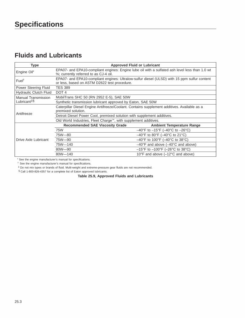
Fluids and LubricantsType Approved Fluid or Lubricant
Engine Oil* EPA07- and EPA10-compliant engines: Engine lube oil with a sulfated ash level less than 1.0 wt%; currently referred to as CJ-4 oil.
Fuel† EPA07- and EPA10-compliant engines: Ultralow-sulfur diesel (ULSD) with 15 ppm sulfur contentor less, based on ASTM D2622 test procedure.
Power Steering Fluid TES 389Hydraulic Clutch Fluid DOT 4Manual TransmissionLubricant‡§
MobilTrans SHC 50 (RN 2952 E-5), SAE 50WSynthetic transmission lubricant approved by Eaton, SAE 50W
Antifreeze
Caterpillar Diesel Engine Antifreeze/Coolant. Contains supplement additives. Available as apremixed solution.Detroit Diesel Power Cool, premixed solution with supplement additives.Old World Industries, Fleet Charge™, with supplement additives.
Drive Axle Lubricant
Recommended SAE Viscosity Grade Ambient Temperature Range75W –40°F to –15°F (–40°C to –26°C)75W—80 –40°F to 80°F (–40°C to 21°C)75W—90 –40°F to 100°F (–40°C to 38°C)75W—140 –40°F and above (–40°C and above)80W—90 –15°F to –100°F (–26°C to 38°C)80W—140 10°F and above (–12°C and above)
* See the engine manufacturer’s manual for specifications.† See the engine manufacturer’s manual for specifications.‡ Do not mix types or brands of fluid. Multi-weight and extreme-pressure gear fluids are not recommended.§ Call 1-800-826-4357 for a complete list of Eaton approved lubricants.
Table 25.9, Approved Fluids and Lubricants
Specifications
25.3
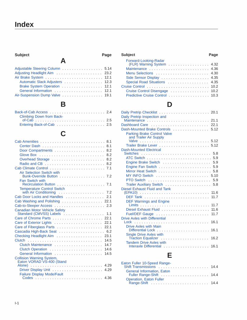
Subject Page
AAdjustable Steering Column . . . . . . . . . . . . . . . . . 5.14Adjusting Headlight Aim . . . . . . . . . . . . . . . . . . . 23.2Air Brake System . . . . . . . . . . . . . . . . . . . . . . . . 12.1
Automatic Slack Adjusters . . . . . . . . . . . . . . . . 12.3Brake System Operation . . . . . . . . . . . . . . . . . 12.1General Information . . . . . . . . . . . . . . . . . . . . 12.1
Air-Suspension Dump Valve . . . . . . . . . . . . . . . . . 19.1
BBack-of-Cab Access . . . . . . . . . . . . . . . . . . . . . . . 2.4
Climbing Down from Back-of-Cab . . . . . . . . . . . . . . . . . . . . . . . . . . . . . 2.5
Entering Back-of-Cab . . . . . . . . . . . . . . . . . . . . 2.5
CCab Amenities . . . . . . . . . . . . . . . . . . . . . . . . . . . 8.1
Center Dash . . . . . . . . . . . . . . . . . . . . . . . . . . 8.1Door Compartments . . . . . . . . . . . . . . . . . . . . . 8.2Glove Box . . . . . . . . . . . . . . . . . . . . . . . . . . . 8.2Overhead Storage . . . . . . . . . . . . . . . . . . . . . . 8.2Radio and CB . . . . . . . . . . . . . . . . . . . . . . . . . 8.2
Cab Climate Control . . . . . . . . . . . . . . . . . . . . . . . 7.1Air Selection Switch with
Bunk-Override Button . . . . . . . . . . . . . . . . . . . 7.2Fan Switch with
Recirculation Button . . . . . . . . . . . . . . . . . . . . 7.1Temperature Control Switch
with Air Conditioning . . . . . . . . . . . . . . . . . . . 7.2Cab Door Locks and Handles . . . . . . . . . . . . . . . . 2.1Cab Washing and Polishing . . . . . . . . . . . . . . . . . 22.1Cab-to-Sleeper Access . . . . . . . . . . . . . . . . . . . . . 2.3Canadian Motor Vehicle Safety
Standard (CMVSS) Labels . . . . . . . . . . . . . . . . . 1.1Care of Chrome Parts . . . . . . . . . . . . . . . . . . . . . 22.1Care of Exterior Lights . . . . . . . . . . . . . . . . . . . . 22.1Care of Fiberglass Parts . . . . . . . . . . . . . . . . . . . 22.1Cascadia High-Back Seat . . . . . . . . . . . . . . . . . . . 6.2Checking Headlight Aim . . . . . . . . . . . . . . . . . . . 23.1Clutch . . . . . . . . . . . . . . . . . . . . . . . . . . . . . . . 14.5
Clutch Maintenance . . . . . . . . . . . . . . . . . . . . 14.7Clutch Operation . . . . . . . . . . . . . . . . . . . . . . 14.6General Information . . . . . . . . . . . . . . . . . . . . 14.5
Collision Warning System,Eaton VORAD VS-400 (StandAlone) . . . . . . . . . . . . . . . . . . . . . . . . . . . . . . 4.29Driver Display Unit . . . . . . . . . . . . . . . . . . . . . 4.29Failure Display Mode/Fault
Codes . . . . . . . . . . . . . . . . . . . . . . . . . . . . 4.36
Subject Page
Forward-Looking-Radar(FLR) Warning System . . . . . . . . . . . . . . . . . 4.32
Maintenance . . . . . . . . . . . . . . . . . . . . . . . . . 4.36Menu Selections . . . . . . . . . . . . . . . . . . . . . . 4.30Side Sensor Display . . . . . . . . . . . . . . . . . . . . 4.35Special Road Situations . . . . . . . . . . . . . . . . . 4.35
Cruise Control . . . . . . . . . . . . . . . . . . . . . . . . . . 10.2Cruise Control Disengage . . . . . . . . . . . . . . . . 10.2Predictive Cruise Control . . . . . . . . . . . . . . . . . 10.3
DDaily Pretrip Checklist . . . . . . . . . . . . . . . . . . . . . 20.1Daily Pretrip Inspection and
Maintenance . . . . . . . . . . . . . . . . . . . . . . . . . . 21.1Dashboard Care . . . . . . . . . . . . . . . . . . . . . . . . 22.1Dash-Mounted Brake Controls . . . . . . . . . . . . . . . 5.12
Parking Brake Control Valveand Trailer Air SupplyValve . . . . . . . . . . . . . . . . . . . . . . . . . . . . . 5.12
Trailer Brake Lever . . . . . . . . . . . . . . . . . . . . . 5.12Dash-Mounted Electrical
Switches . . . . . . . . . . . . . . . . . . . . . . . . . . . . . 5.8ATC Switch . . . . . . . . . . . . . . . . . . . . . . . . . . . 5.9Engine Brake Switch . . . . . . . . . . . . . . . . . . . . 5.9Engine Fan Switch . . . . . . . . . . . . . . . . . . . . . . 5.9Mirror Heat Switch . . . . . . . . . . . . . . . . . . . . . . 5.8MY INFO Switch . . . . . . . . . . . . . . . . . . . . . . 5.10PTO Switch . . . . . . . . . . . . . . . . . . . . . . . . . . 5.9Trailer Auxiliary Switch . . . . . . . . . . . . . . . . . . . 5.8
Diesel Exhaust Fluid and Tank(EPA10) . . . . . . . . . . . . . . . . . . . . . . . . . . . . . 11.6DEF Tank . . . . . . . . . . . . . . . . . . . . . . . . . . . 11.7DEF Warnings and Engine
Limits . . . . . . . . . . . . . . . . . . . . . . . . . . . . . 11.7Diesel Exhaust Fluid . . . . . . . . . . . . . . . . . . . . 11.6Fuel/DEF Gauge . . . . . . . . . . . . . . . . . . . . . . 11.7
Drive Axles with DifferentialLock . . . . . . . . . . . . . . . . . . . . . . . . . . . . . . . 16.1Drive Axles with Main
Differential Lock . . . . . . . . . . . . . . . . . . . . . . 16.1Single Drive Axles with
Traction Equalizer . . . . . . . . . . . . . . . . . . . . 16.2Tandem Drive Axles with
Interaxle Differential . . . . . . . . . . . . . . . . . . . 16.1
EEaton Fuller 10-Speed Range-
Shift Transmissions . . . . . . . . . . . . . . . . . . . . . 14.4General Information, Eaton
Fuller Range-Shift . . . . . . . . . . . . . . . . . . . . 14.4Operation, Eaton Fuller
Range-Shift . . . . . . . . . . . . . . . . . . . . . . . . 14.4
Index
I-1
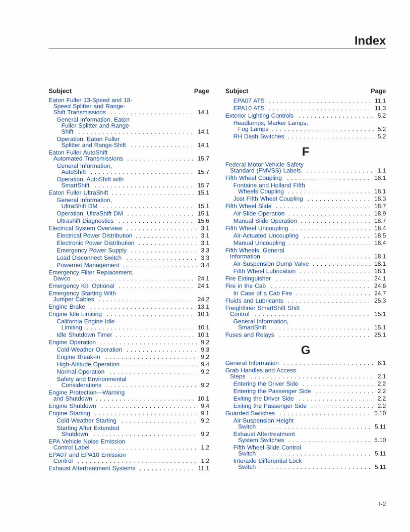
Subject PageEaton Fuller 13-Speed and 18-
Speed Splitter and Range-Shift Transmissions . . . . . . . . . . . . . . . . . . . . . 14.1General Information, Eaton
Fuller Splitter and Range-Shift . . . . . . . . . . . . . . . . . . . . . . . . . . . . . 14.1
Operation, Eaton FullerSplitter and Range-Shift . . . . . . . . . . . . . . . . 14.1
Eaton Fuller AutoShiftAutomated Transmissions . . . . . . . . . . . . . . . . . 15.7General Information,
AutoShift . . . . . . . . . . . . . . . . . . . . . . . . . . 15.7Operation, AutoShift with
SmartShift . . . . . . . . . . . . . . . . . . . . . . . . . 15.7Eaton Fuller UltraShift . . . . . . . . . . . . . . . . . . . . . 15.1
General Information,UltraShift DM . . . . . . . . . . . . . . . . . . . . . . . 15.1
Operation, UltraShift DM . . . . . . . . . . . . . . . . . 15.1Ultrashift Diagnostics . . . . . . . . . . . . . . . . . . . 15.6
Electrical System Overview . . . . . . . . . . . . . . . . . . 3.1Electrical Power Distribution . . . . . . . . . . . . . . . . 3.1Electronic Power Distribution . . . . . . . . . . . . . . . 3.1Emergency Power Supply . . . . . . . . . . . . . . . . . 3.3Load Disconnect Switch . . . . . . . . . . . . . . . . . . 3.3Powernet Management . . . . . . . . . . . . . . . . . . . 3.4
Emergency Filter Replacement,Davco . . . . . . . . . . . . . . . . . . . . . . . . . . . . . . 24.1
Emergency Kit, Optional . . . . . . . . . . . . . . . . . . . 24.1Emergency Starting With
Jumper Cables . . . . . . . . . . . . . . . . . . . . . . . . 24.2Engine Brake . . . . . . . . . . . . . . . . . . . . . . . . . . 13.1Engine Idle Limiting . . . . . . . . . . . . . . . . . . . . . . 10.1
California Engine IdleLimiting . . . . . . . . . . . . . . . . . . . . . . . . . . . 10.1
Idle Shutdown Timer . . . . . . . . . . . . . . . . . . . . 10.1Engine Operation . . . . . . . . . . . . . . . . . . . . . . . . . 9.2
Cold-Weather Operation . . . . . . . . . . . . . . . . . . 9.3Engine Break-In . . . . . . . . . . . . . . . . . . . . . . . 9.2High-Altitude Operation . . . . . . . . . . . . . . . . . . . 9.4Normal Operation . . . . . . . . . . . . . . . . . . . . . . 9.2Safety and Environmental
Considerations . . . . . . . . . . . . . . . . . . . . . . . 9.2Engine Protection—Warning
and Shutdown . . . . . . . . . . . . . . . . . . . . . . . . . 10.1Engine Shutdown . . . . . . . . . . . . . . . . . . . . . . . . 9.4Engine Starting . . . . . . . . . . . . . . . . . . . . . . . . . . 9.1
Cold-Weather Starting . . . . . . . . . . . . . . . . . . . 9.2Starting After Extended
Shutdown . . . . . . . . . . . . . . . . . . . . . . . . . . 9.2EPA Vehicle Noise Emission
Control Label . . . . . . . . . . . . . . . . . . . . . . . . . . 1.2EPA07 and EPA10 Emission
Control . . . . . . . . . . . . . . . . . . . . . . . . . . . . . . 1.2Exhaust Aftertreatment Systems . . . . . . . . . . . . . . 11.1
Subject Page
EPA07 ATS . . . . . . . . . . . . . . . . . . . . . . . . . . 11.1EPA10 ATS . . . . . . . . . . . . . . . . . . . . . . . . . . 11.3
Exterior Lighting Controls . . . . . . . . . . . . . . . . . . . 5.2Headlamps, Marker Lamps,
Fog Lamps . . . . . . . . . . . . . . . . . . . . . . . . . . 5.2RH Dash Switches . . . . . . . . . . . . . . . . . . . . . . 5.2
FFederal Motor Vehicle Safety
Standard (FMVSS) Labels . . . . . . . . . . . . . . . . . 1.1Fifth Wheel Coupling . . . . . . . . . . . . . . . . . . . . . 18.1
Fontaine and Holland FifthWheels Coupling . . . . . . . . . . . . . . . . . . . . . 18.1
Jost Fifth Wheel Coupling . . . . . . . . . . . . . . . . 18.3Fifth Wheel Slide . . . . . . . . . . . . . . . . . . . . . . . . 18.7
Air Slide Operation . . . . . . . . . . . . . . . . . . . . . 18.9Manual Slide Operation . . . . . . . . . . . . . . . . . . 18.7
Fifth Wheel Uncoupling . . . . . . . . . . . . . . . . . . . . 18.4Air-Actuated Uncoupling . . . . . . . . . . . . . . . . . 18.5Manual Uncoupling . . . . . . . . . . . . . . . . . . . . . 18.4
Fifth Wheels, GeneralInformation . . . . . . . . . . . . . . . . . . . . . . . . . . . 18.1Air-Suspension Dump Valve . . . . . . . . . . . . . . . 18.1Fifth Wheel Lubrication . . . . . . . . . . . . . . . . . . 18.1
Fire Extinguisher . . . . . . . . . . . . . . . . . . . . . . . . 24.1Fire in the Cab . . . . . . . . . . . . . . . . . . . . . . . . . 24.6
In Case of a Cab Fire . . . . . . . . . . . . . . . . . . . 24.7Fluids and Lubricants . . . . . . . . . . . . . . . . . . . . . 25.3Freightliner SmartShift Shift
Control . . . . . . . . . . . . . . . . . . . . . . . . . . . . . 15.1General Information,
SmartShift . . . . . . . . . . . . . . . . . . . . . . . . . 15.1Fuses and Relays . . . . . . . . . . . . . . . . . . . . . . . 25.1
GGeneral Information . . . . . . . . . . . . . . . . . . . . . . . 6.1Grab Handles and Access
Steps . . . . . . . . . . . . . . . . . . . . . . . . . . . . . . . 2.1Entering the Driver Side . . . . . . . . . . . . . . . . . . 2.2Entering the Passenger Side . . . . . . . . . . . . . . . 2.2Exiting the Driver Side . . . . . . . . . . . . . . . . . . . 2.2Exiting the Passenger Side . . . . . . . . . . . . . . . . 2.2
Guarded Switches . . . . . . . . . . . . . . . . . . . . . . . 5.10Air-Suspension Height
Switch . . . . . . . . . . . . . . . . . . . . . . . . . . . . 5.11Exhaust Aftertreatment
System Switches . . . . . . . . . . . . . . . . . . . . . 5.10Fifth Wheel Slide Control
Switch . . . . . . . . . . . . . . . . . . . . . . . . . . . . 5.11Interaxle Differential Lock
Switch . . . . . . . . . . . . . . . . . . . . . . . . . . . . 5.11
Index
I-2
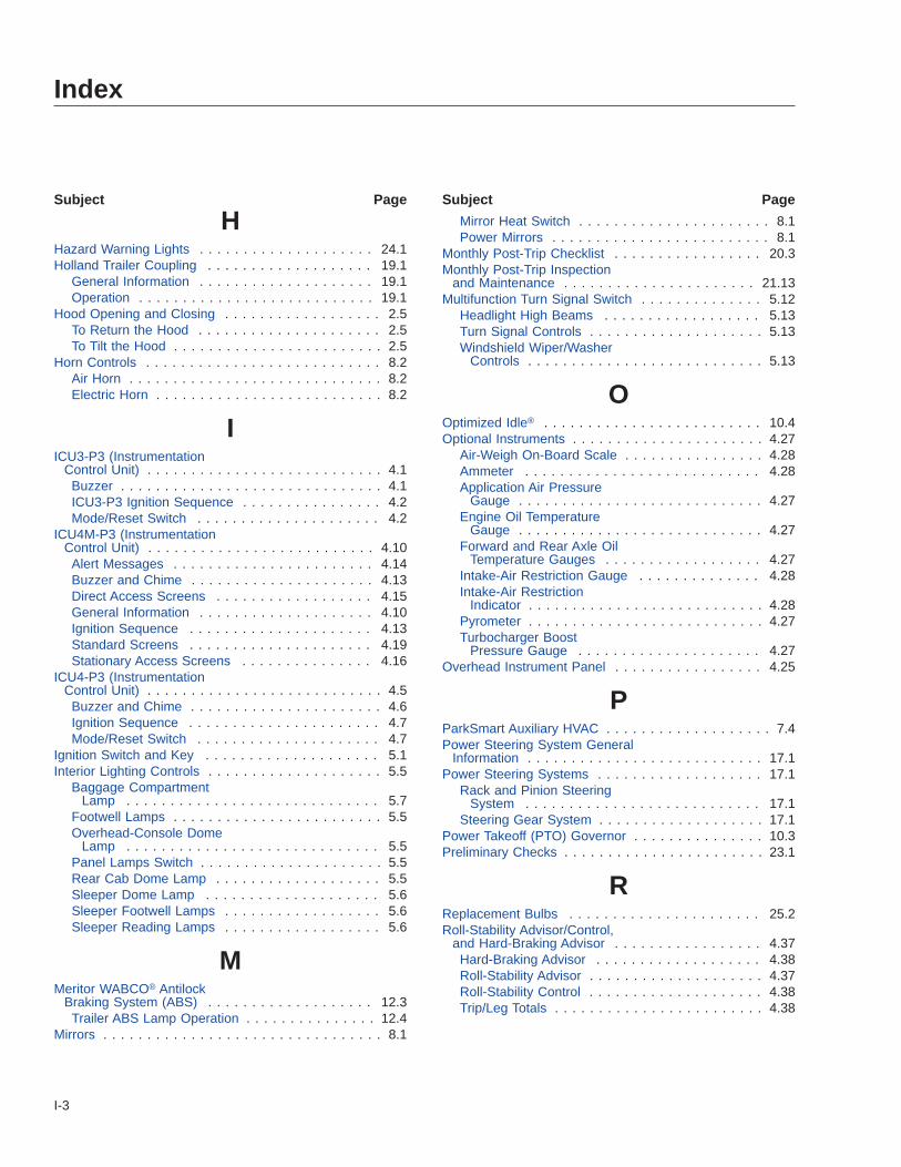
Subject Page
HHazard Warning Lights . . . . . . . . . . . . . . . . . . . . 24.1Holland Trailer Coupling . . . . . . . . . . . . . . . . . . . 19.1
General Information . . . . . . . . . . . . . . . . . . . . 19.1Operation . . . . . . . . . . . . . . . . . . . . . . . . . . . 19.1
Hood Opening and Closing . . . . . . . . . . . . . . . . . . 2.5To Return the Hood . . . . . . . . . . . . . . . . . . . . . 2.5To Tilt the Hood . . . . . . . . . . . . . . . . . . . . . . . . 2.5
Horn Controls . . . . . . . . . . . . . . . . . . . . . . . . . . . 8.2Air Horn . . . . . . . . . . . . . . . . . . . . . . . . . . . . . 8.2Electric Horn . . . . . . . . . . . . . . . . . . . . . . . . . . 8.2
IICU3-P3 (Instrumentation
Control Unit) . . . . . . . . . . . . . . . . . . . . . . . . . . . 4.1Buzzer . . . . . . . . . . . . . . . . . . . . . . . . . . . . . . 4.1ICU3-P3 Ignition Sequence . . . . . . . . . . . . . . . . 4.2Mode/Reset Switch . . . . . . . . . . . . . . . . . . . . . 4.2
ICU4M-P3 (InstrumentationControl Unit) . . . . . . . . . . . . . . . . . . . . . . . . . . 4.10Alert Messages . . . . . . . . . . . . . . . . . . . . . . . 4.14Buzzer and Chime . . . . . . . . . . . . . . . . . . . . . 4.13Direct Access Screens . . . . . . . . . . . . . . . . . . 4.15General Information . . . . . . . . . . . . . . . . . . . . 4.10Ignition Sequence . . . . . . . . . . . . . . . . . . . . . 4.13Standard Screens . . . . . . . . . . . . . . . . . . . . . 4.19Stationary Access Screens . . . . . . . . . . . . . . . 4.16
ICU4-P3 (InstrumentationControl Unit) . . . . . . . . . . . . . . . . . . . . . . . . . . . 4.5Buzzer and Chime . . . . . . . . . . . . . . . . . . . . . . 4.6Ignition Sequence . . . . . . . . . . . . . . . . . . . . . . 4.7Mode/Reset Switch . . . . . . . . . . . . . . . . . . . . . 4.7
Ignition Switch and Key . . . . . . . . . . . . . . . . . . . . 5.1Interior Lighting Controls . . . . . . . . . . . . . . . . . . . . 5.5
Baggage CompartmentLamp . . . . . . . . . . . . . . . . . . . . . . . . . . . . . 5.7
Footwell Lamps . . . . . . . . . . . . . . . . . . . . . . . . 5.5Overhead-Console Dome
Lamp . . . . . . . . . . . . . . . . . . . . . . . . . . . . . 5.5Panel Lamps Switch . . . . . . . . . . . . . . . . . . . . . 5.5Rear Cab Dome Lamp . . . . . . . . . . . . . . . . . . . 5.5Sleeper Dome Lamp . . . . . . . . . . . . . . . . . . . . 5.6Sleeper Footwell Lamps . . . . . . . . . . . . . . . . . . 5.6Sleeper Reading Lamps . . . . . . . . . . . . . . . . . . 5.6
MMeritor WABCO® Antilock
Braking System (ABS) . . . . . . . . . . . . . . . . . . . 12.3Trailer ABS Lamp Operation . . . . . . . . . . . . . . . 12.4
Mirrors . . . . . . . . . . . . . . . . . . . . . . . . . . . . . . . . 8.1
Subject Page
Mirror Heat Switch . . . . . . . . . . . . . . . . . . . . . . 8.1Power Mirrors . . . . . . . . . . . . . . . . . . . . . . . . . 8.1
Monthly Post-Trip Checklist . . . . . . . . . . . . . . . . . 20.3Monthly Post-Trip Inspection
and Maintenance . . . . . . . . . . . . . . . . . . . . . . 21.13Multifunction Turn Signal Switch . . . . . . . . . . . . . . 5.12
Headlight High Beams . . . . . . . . . . . . . . . . . . 5.13Turn Signal Controls . . . . . . . . . . . . . . . . . . . . 5.13Windshield Wiper/Washer
Controls . . . . . . . . . . . . . . . . . . . . . . . . . . . 5.13
OOptimized Idle® . . . . . . . . . . . . . . . . . . . . . . . . . 10.4Optional Instruments . . . . . . . . . . . . . . . . . . . . . . 4.27
Air-Weigh On-Board Scale . . . . . . . . . . . . . . . . 4.28Ammeter . . . . . . . . . . . . . . . . . . . . . . . . . . . 4.28Application Air Pressure
Gauge . . . . . . . . . . . . . . . . . . . . . . . . . . . . 4.27Engine Oil Temperature
Gauge . . . . . . . . . . . . . . . . . . . . . . . . . . . . 4.27Forward and Rear Axle Oil
Temperature Gauges . . . . . . . . . . . . . . . . . . 4.27Intake-Air Restriction Gauge . . . . . . . . . . . . . . 4.28Intake-Air Restriction
Indicator . . . . . . . . . . . . . . . . . . . . . . . . . . . 4.28Pyrometer . . . . . . . . . . . . . . . . . . . . . . . . . . . 4.27Turbocharger Boost
Pressure Gauge . . . . . . . . . . . . . . . . . . . . . 4.27Overhead Instrument Panel . . . . . . . . . . . . . . . . . 4.25
PParkSmart Auxiliary HVAC . . . . . . . . . . . . . . . . . . . 7.4Power Steering System General
Information . . . . . . . . . . . . . . . . . . . . . . . . . . . 17.1Power Steering Systems . . . . . . . . . . . . . . . . . . . 17.1
Rack and Pinion SteeringSystem . . . . . . . . . . . . . . . . . . . . . . . . . . . 17.1
Steering Gear System . . . . . . . . . . . . . . . . . . . 17.1Power Takeoff (PTO) Governor . . . . . . . . . . . . . . . 10.3Preliminary Checks . . . . . . . . . . . . . . . . . . . . . . . 23.1
RReplacement Bulbs . . . . . . . . . . . . . . . . . . . . . . 25.2Roll-Stability Advisor/Control,
and Hard-Braking Advisor . . . . . . . . . . . . . . . . . 4.37Hard-Braking Advisor . . . . . . . . . . . . . . . . . . . 4.38Roll-Stability Advisor . . . . . . . . . . . . . . . . . . . . 4.37Roll-Stability Control . . . . . . . . . . . . . . . . . . . . 4.38Trip/Leg Totals . . . . . . . . . . . . . . . . . . . . . . . . 4.38
Index
I-3
Subject PageRollTek Rollover Protection
System . . . . . . . . . . . . . . . . . . . . . . . . . . . . . . 6.8Identification . . . . . . . . . . . . . . . . . . . . . . . . . . 6.8Inspection and Service . . . . . . . . . . . . . . . . . . 6.10Operation . . . . . . . . . . . . . . . . . . . . . . . . . . . . 6.9
SSears Atlas Seat . . . . . . . . . . . . . . . . . . . . . . . . . 6.2Seat Belts and Tether Belts . . . . . . . . . . . . . . . . . . 6.3
General Information . . . . . . . . . . . . . . . . . . . . . 6.3Seat Belt Inspection . . . . . . . . . . . . . . . . . . . . . 6.5Seat Belt Operation . . . . . . . . . . . . . . . . . . . . . 6.5
Sleeper Climate Control . . . . . . . . . . . . . . . . . . . . 7.3Cab-Override Operation . . . . . . . . . . . . . . . . . . 7.4Fan Switch . . . . . . . . . . . . . . . . . . . . . . . . . . . 7.3Temperature Control Switch
with Air Conditioning . . . . . . . . . . . . . . . . . . . 7.3Sleeper Door . . . . . . . . . . . . . . . . . . . . . . . . . . . 2.3Sleeper Luggage Door . . . . . . . . . . . . . . . . . . . . . 2.4Speedometer and Tachometer . . . . . . . . . . . . . . . 4.25
Speedometer . . . . . . . . . . . . . . . . . . . . . . . . 4.25Tachometer . . . . . . . . . . . . . . . . . . . . . . . . . . 4.25
Standard Instruments . . . . . . . . . . . . . . . . . . . . . 4.25Coolant Temperature Gauge . . . . . . . . . . . . . . 4.26Engine Oil Pressure Gauge . . . . . . . . . . . . . . . 4.25Fuel Gauge . . . . . . . . . . . . . . . . . . . . . . . . . . 4.26Fuel/Diesel Exhaust Fluid
(DEF) Gauge (EPA10) . . . . . . . . . . . . . . . . . 4.26Primary and Secondary Air
Pressure Gauges . . . . . . . . . . . . . . . . . . . . . 4.26Transmission Oil
Temperature Gauge . . . . . . . . . . . . . . . . . . . 4.26Voltmeter . . . . . . . . . . . . . . . . . . . . . . . . . . . 4.26
Steering Wheel Air Bag . . . . . . . . . . . . . . . . . . . . . 6.7Steering-Wheel-Mounted
Controls . . . . . . . . . . . . . . . . . . . . . . . . . . . . . 5.14Left-Hand Switch Pod,
Cruise Control . . . . . . . . . . . . . . . . . . . . . . . 5.14Right-Hand Switch Pod,
Convenience Functions . . . . . . . . . . . . . . . . . 5.14
TTire and Rim Labels . . . . . . . . . . . . . . . . . . . . . . . 1.2Towing . . . . . . . . . . . . . . . . . . . . . . . . . . . . . . . 24.4
Front Towing Hookup . . . . . . . . . . . . . . . . . . . 24.5Rear Towing Hookup . . . . . . . . . . . . . . . . . . . 24.5
Two-Speed Drive Axles . . . . . . . . . . . . . . . . . . . . 16.2Axle Shift . . . . . . . . . . . . . . . . . . . . . . . . . . . 16.2
Subject Page
VVehicle Specification Decal . . . . . . . . . . . . . . . . . . 1.1Velour Upholstery Cleaning . . . . . . . . . . . . . . . . . 22.2
Chewing Gum or Wax . . . . . . . . . . . . . . . . . . . 22.3Grease and Oil-Based Stains . . . . . . . . . . . . . . 22.3Mildew . . . . . . . . . . . . . . . . . . . . . . . . . . . . . 22.3Sugar and Water-Based
Stains . . . . . . . . . . . . . . . . . . . . . . . . . . . . 22.3Vinyl Upholstery Cleaning . . . . . . . . . . . . . . . . . . 22.2
Ball Point Ink . . . . . . . . . . . . . . . . . . . . . . . . . 22.2Chewing Gum . . . . . . . . . . . . . . . . . . . . . . . . 22.2Miscellaneous . . . . . . . . . . . . . . . . . . . . . . . . 22.2Nail Polish and Nail Polish
Remover . . . . . . . . . . . . . . . . . . . . . . . . . . 22.2Ordinary Dirt . . . . . . . . . . . . . . . . . . . . . . . . . 22.2Paint, Shoe Heel Marks . . . . . . . . . . . . . . . . . 22.2Shoe Polish . . . . . . . . . . . . . . . . . . . . . . . . . 22.2Sulfide Stains . . . . . . . . . . . . . . . . . . . . . . . . 22.2Tars, Asphalts, and Creosote . . . . . . . . . . . . . . 22.2
WWarning and Indicator Lights . . . . . . . . . . . . . . . . 4.23Weekly Post-Trip Checklist . . . . . . . . . . . . . . . . . . 20.3Weekly Post-Trip Inspection
and Maintenance . . . . . . . . . . . . . . . . . . . . . . 21.11Windows . . . . . . . . . . . . . . . . . . . . . . . . . . . . . . 8.1Windshield Washer Reservoir . . . . . . . . . . . . . . . . 8.2
Index
I-4