Embed Size (px)
Citation preview
Formula SAE Powertrain Phase 4: Performance Validation and
Path Forward
Sponsor: Mr. Paul Schwarz
Advisor:
Dr. Steve Timmins
December 10th 2010
2
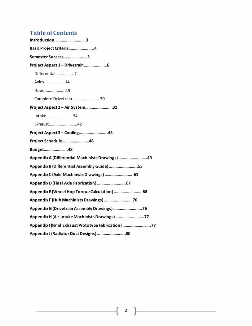
Table of Contents Introduction………………………..3
Basic Project Criteria…………………..4
Semester Success………………….5
Project Aspect 1 – Drivetrain…………………6
Differential……………..7
Axles……………….14
Hubs………………..19
Complete Drivetrain……………………..30
Project Aspect 2 – Air System…………………….31
Intake…………………….34
Exhaust……………………..42
Project Aspect 3 – Cooling……………………..45
Project Schedule…………………….48
Budget………………….48
Appendix A (Differential Machinists Drawings) ……………………..49
Appendix B (Differential Assembly Guide) ……………………..55
Appendix C (Axle Machinists Drawings) ……………………..61
Appendix D (Final Axle Fabrication) ……………………..67
Appendix E (Wheel Hop Torque Calculation) ……………………..68
Appendix F (Hub Machinists Drawings) ……………………..70
Appendix G (Drivetrain Assembly Drawings) ……………………..76
Appendix H (Air Intake Machinists Drawings) ……………………..77
Appendix I (Final Exhaust Prototype Fabrication) ……………………..77
Appendix J (Radiator Duct Designs) ……………………..80
3
Introduction:
Team FSAE Powertrain has made tremendous strides in the final phase of the Senior Design Process. As this phase, and the semester, comes to an end, our team has complete manufacturing of the majority of components and hammered out a very clear path forward for future work in all project aspects.
Our group’s work on the powertrain for the 2010-11 FSAE car was divided into 3 major project aspects, with some additional breakdowns under them.
1. Drivetrain
a. Differential b. Axles c. Hubs
2. Air System a. Air Intake b. Exhaust
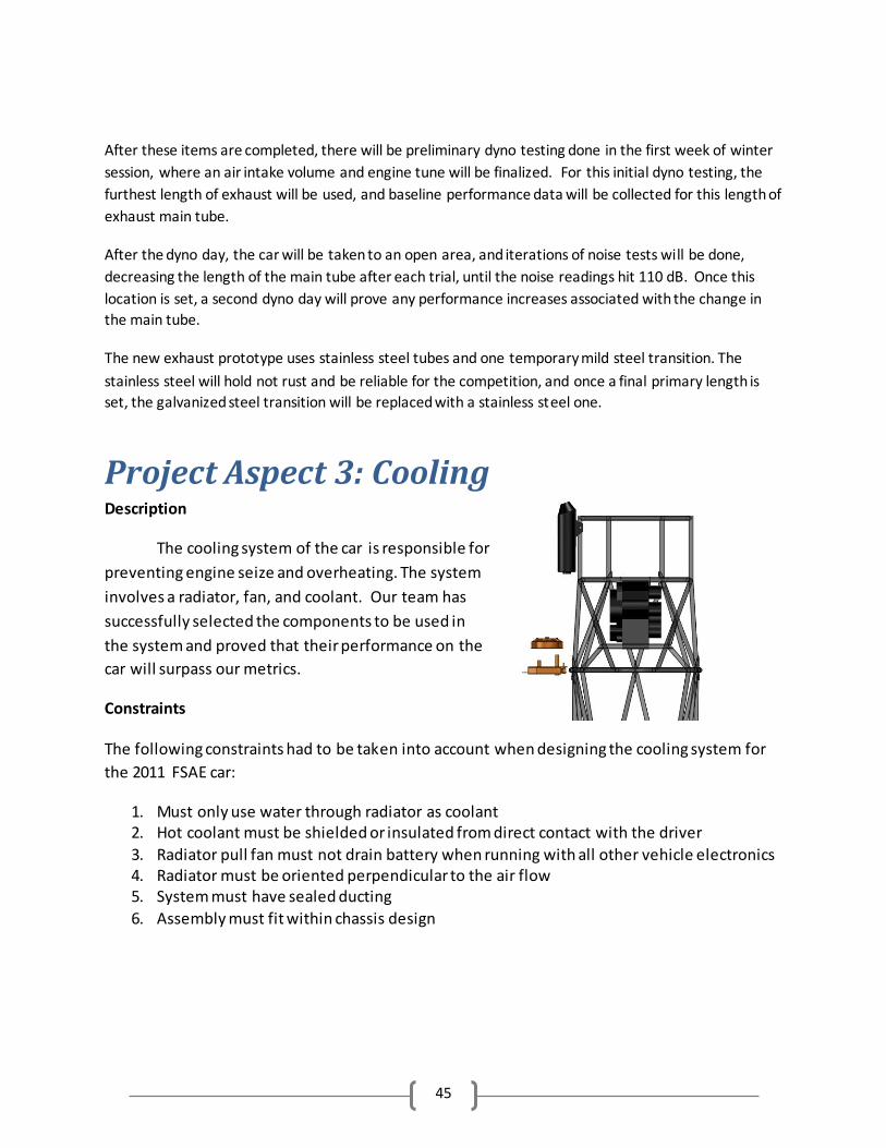
3. Cooling
The wiring harness for the 2010-11 car will be taken on by William “Jay” Kistler as an Honors project and will be completed early in winter session 2011.
As we manufactured our way through phase 4 our list of tangible deliverables which will be completed by the end of the semester along with the report, poster, presentation, and other various paperwork required by the MEEG401 syllabus, had to change slightly. The final list is as follows…
1. 1 limited slip differential, complete with custom housing and mounting fixtures ready for placement in the 2010-11 car
2. 2 axles ready to be installed in 2010-11 car 3. 2 rear drive hubs ready for interface with axles, suspension components, brake components,
and wheels, ready to be installed in 2010-11 car 4. 2 aluminum spacers ready for use in the rear hub assemblies of the 2010-11 car 5. 1 prototyped air intake with expandable plenum and runner tube that will assist in the
design of the final 2010-11 air intake and can be saved for design work in future years 6. Air filter, throttle body, fuel injector, rubber gasket, throttle position sensor, and mass flow
sensor to accompany the future air intake on the 2010-11 car 7. 1 exhaust maintube, including O2 sensor, ready for installation between the head and
muffler of the 2010-11 car 8. 1 radiator for the 2010-11 car 9. 1 radiator pull fan for the 2010-11 car 10. Plans for 2 radiator ducts—one leading up to the radiator and connecting the radiator to the
puller fan to be given to the Chassis team for incorporation into their sidepod design
4
The following report will be broken down into the three main aspects of our project. All other powertrain componentry and systems other than those touched on in the introduction and elaborated on throughout the report are out of the scope of our project.
Basic Project Criteria:
There are a few constraints/wants/metrics that apply to all of the aspects of our project and are therefore discussed in detail in the majority of the following report sections in such a way that is pertinent to the system being discussed. This basic criteria as well as more specific project requirements were assembled from interactions with our costumer, Mr. Paul Schwarz, our advisor, Dr. Steve Timmins, and current veteran SAE club members. Much information was also gathered from the FSAE rule book to help set the bounds of our project. Cost Constraint: The cost of the whole project may not exceed $1,000. See the Budget section near the end of this report for breakdown. Weight Want: Weight reduction is a want that applies to every aspect of our project. This reduction allows the vehicle to retain its maximum power to weight ratio. Durability / Reliability Want: It is imperative that we develop robust designs that will allow the 2010-11 car to finish competition and serve as a baseline for future years optimization. Aesthetics/Neatness/Workmanship Want: Finally our customer, Paul Schwarz, strongly expressed that all system attributed to our team be neat and well manufactured. Many previous UD SAE cars were very hastily assembled only weeks (or even days) before competition. This resulted in sloppy assemblies and a negative aesthetic quality.
Performance: While the focus this year was on creating durable designs there was a desire to have
everything perform well to allow the SAE club to not only finish, but excel at competition.
5
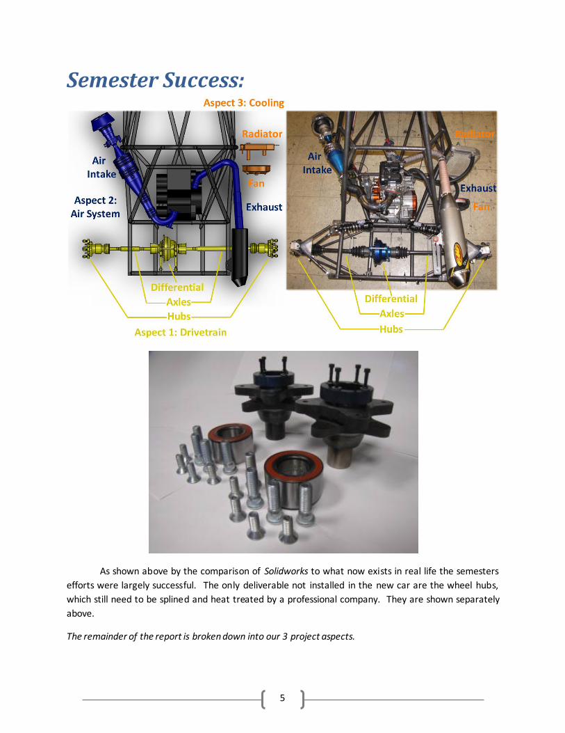
Semester Success:
As shown above by the comparison of Solidworks to what now exists in real life the semesters
efforts were largely successful. The only deliverable not installed in the new car are the wheel hubs,
which still need to be splined and heat treated by a professional company. They are shown separately
above.
The remainder of the report is broken down into our 3 project aspects.
6
Project Aspect 1: Drivetrain (Differential,
Axles, and Hubs)
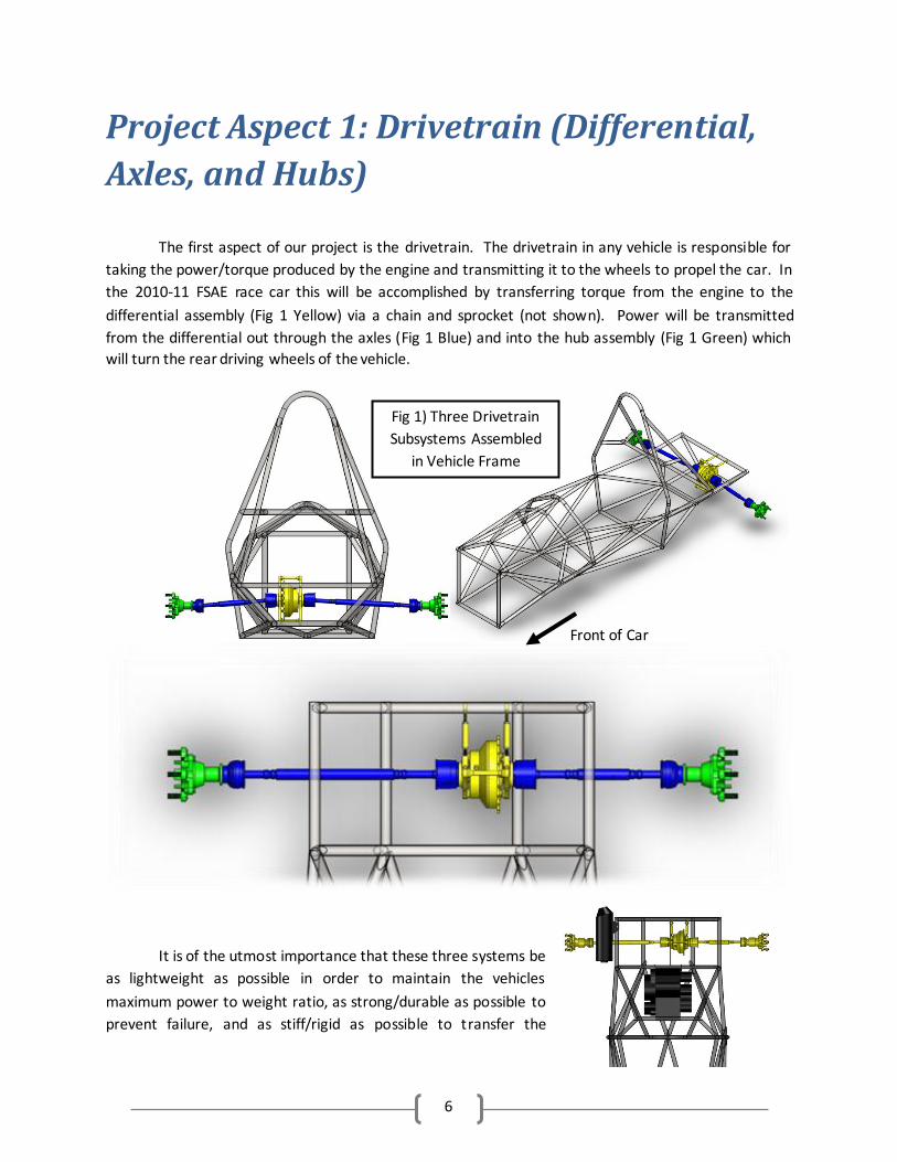
The first aspect of our project is the drivetrain. The drivetrain in any vehicle is responsible for
taking the power/torque produced by the engine and transmitting it to the wheels to propel the car. In
the 2010-11 FSAE race car this will be accomplished by transferring torque from the engine to the
differential assembly (Fig 1 Yellow) via a chain and sprocket (not shown). Power will be transmitted
from the differential out through the axles (Fig 1 Blue) and into the hub assembly (Fig 1 Green) which
will turn the rear driving wheels of the vehicle.
It is of the utmost importance that these three systems be
as lightweight as possible in order to maintain the vehicles
maximum power to weight ratio, as strong/durable as possible to
prevent failure, and as stiff/rigid as possible to transfer the
Fig 1) Three Drivetrain
Subsystems Assembled
in Vehicle Frame
Front of Car
7
engine’s torque to the wheels with minimum energy losses. The reminder of the Project Aspect 1:
Drivetrain section is organized in these three subsystems moving from the interior or the vehicle out—
differential, axles, hubs.
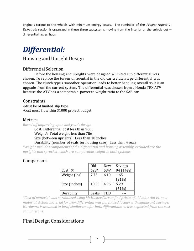
Differential: Housing and Upright Design Differential Selection Before the housing and uprights were designed a limited slip differential was chosen. To replace the torsen differential in the old car, a clutch type differential was chosen. The clutch type’s smoother operation leads to better handling overall so it is an upgrade from the current system. The differential was chosen from a Honda TRX ATV because the ATV has a comparable power to weight ratio to the SAE car.
Constraints -Must be of limited slip type -Cost must fit within $1000 project budget
Metrics Based off improving upon last year’s design
Cost: Differential cost less than $600 Weight*: Total weight less than 7lbs Size (between uprights): Less than 10 inches Durability (number of seals for housing case): Less than 4 seals
*Weight includes components of the differential and housing assembly, excluded are the uprights and sprocket which are comparable weight in both systems.
Comparison Old New Savings Cost ($) 628* 534* 94 (14%) Weight (lbs) 7.75 6.10 1.65
(21%) Size (inches) 10.25 4.96 5.29
(51%) Durability Leaks TBD ---
*Cost of material was normalized using McMaster Carr to find prices of old material vs. new material. Actual material for new differential was purchased locally with significant savings. Hardware is assumed to be of similar cost for both differentials so it is neglected from the cost comparisons.
Final Design Considerations
8
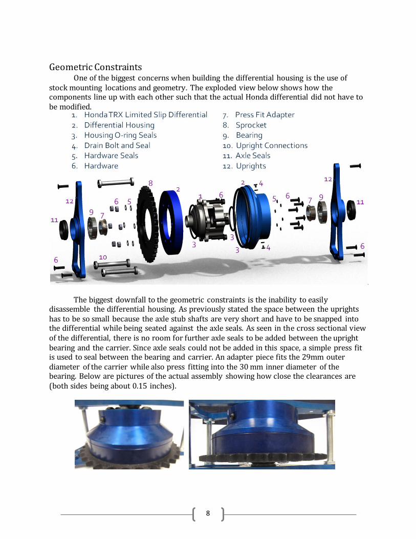
Geometric Constraints
One of the biggest concerns when building the differential housing is the use of stock mounting locations and geometry. The exploded view below shows how the components line up with each other such that the actual Honda differential did not have to be modified.
The biggest downfall to the geometric constraints is the inability to easily disassemble the differential housing. As previously stated the space between the uprights has to be so small because the axle stub shafts are very short and have to be snapped into the differential while being seated against the axle seals. As seen in the cross sectional view of the differential, there is no room for further axle seals to be added between the upright bearing and the carrier. Since axle seals could not be added in this space, a simple press fit is used to seal between the bearing and carrier. An adapter piece fits the 29mm outer diameter of the carrier while also press fitting into the 30 mm inner diameter of the bearing. Below are pictures of the actual assembly showing how close the clearances are (both sides being about 0.15 inches).
9
Modification to Design Machine Shop Advisement A great asset to the successful build of the differential assembly is greatly due to the help of the mechanic in charge of the mechanical engineering machine shop, Mr. Beard. While working though each drawing to help best come up with a method of properly manufacturing each part, Mr. Beard advised several changes to the design of the differential housing. Most of these changes were done to either make assembly or manufacturing easier, but in the end simplified the part leading to a more elegant design overall. The first change suggested by Mr. Beard was the decreased radius of the taper on the upright connections. The radius decreases stress concentrations to some degree, but is mostly aesthetic with little validation to use the specified radius. In the machine shop was a bit that could be used on the lathe that had a generic radius built in. This tool still provides a radius and would be much more consistent than attempting to fillet the part by hand so it was used instead of what was specified in the drawing. The sprocket side of the housing had features that could be revised to ease machining with little to no loss in the mechanics of the housing. Initially there was a lip on this half of the housing on both the inside and the outside of the interface with the non-sprocket side. After some discussion it was decided that solely the outer lip could locate the non-sprocket side of the housing. With this realization the inner lip neither improved the ability to assemble the housing nor did it provide any benefit to sealing. Also since the lip would be difficult to machine due to tool size restrictions in the shop it was decided that the removal of the inner lip would only decrease weight of the overall assembly. The next thing up for discussion was the fitment of the sprocket and non-sprocket sides of the housing. Since a face sealed o-ring is the sealing feature at the interface of both halves of the housing, having the two aluminum pieces meet face to face at the lip interface could be detrimental. If the aluminum faces met it would restrict the compression of the o-ring which could go unnoticed after assembly. Since this lack of compression would result in failure to hold a seal at the interface it was decided to make the housing with a small gap between the two housing halves. An added benefit to this decision is the removal of the small groove which was initially a feature for a screw driver to pry the casing apart. With the small gap between halves of the housing, this feature was removed from the part. Lastly a final feature was removed from the sprocket side of the differential housing. The initial plan included aluminum tabs that protruded through the sprocket. The idea was to provide further support to the sprocket, such that the bolts would not have to support as much of the load in the case of the friction between the sprocket and housing was not enough to prevent slippage. Although some analysis proved that the bolts would have significantly more strength than necessary to support the possible impulse torque, the feature remained on the drawing to be machined. After some discussion this feature proved to be very difficult to machine and it was suggested that dowels be pressed fit into the face of the sprocket half of the housing rather than a direct protrusion. Seeing as dowels would have little to no reasonable effect in the case of loading, this feature was removed from the part.
10
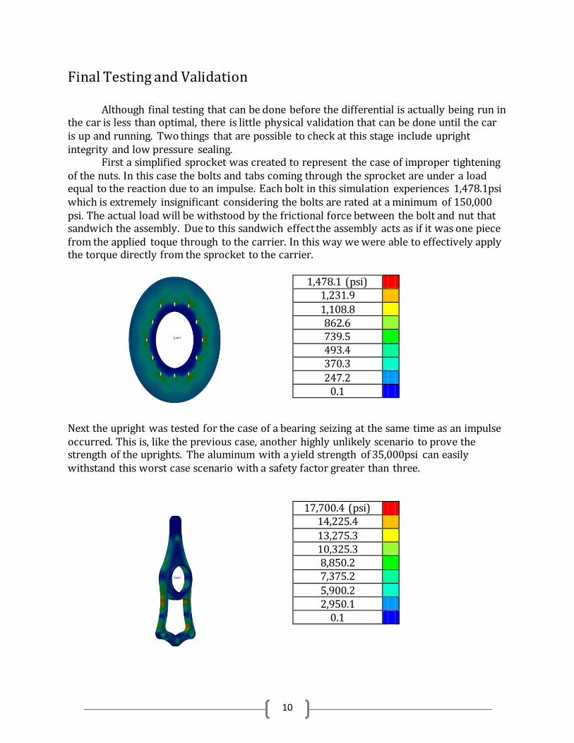
Final Testing and Validation Although final testing that can be done before the differential is actually being run in the car is less than optimal, there is little physical validation that can be done until the car is up and running. Two things that are possible to check at this stage include upright integrity and low pressure sealing.
First a simplified sprocket was created to represent the case of improper tightening of the nuts. In this case the bolts and tabs coming through the sprocket are under a load equal to the reaction due to an impulse. Each bolt in this simulation experiences 1,478.1psi which is extremely insignificant considering the bolts are rated at a minimum of 150,000 psi. The actual load will be withstood by the frictional force between the bolt and nut that sandwich the assembly. Due to this sandwich effect the assembly acts as if it was one piece from the applied toque through to the carrier. In this way we were able to effectively apply the torque directly from the sprocket to the carrier.
1,478.1 (psi) 1,231.9
1,108.8 862.6 739.5 493.4 370.3
247.2 0.1
Next the upright was tested for the case of a bearing seizing at the same time as an impulse occurred. This is, like the previous case, another highly unlikely scenario to prove the strength of the uprights. The aluminum with a yield strength of 35,000psi can easily withstand this worst case scenario with a safety factor greater than three.
17,700.4 (psi) 14,225.4
13,275.3 10,325.3 8,850.2 7,375.2
5,900.2 2,950.1
0.1
11
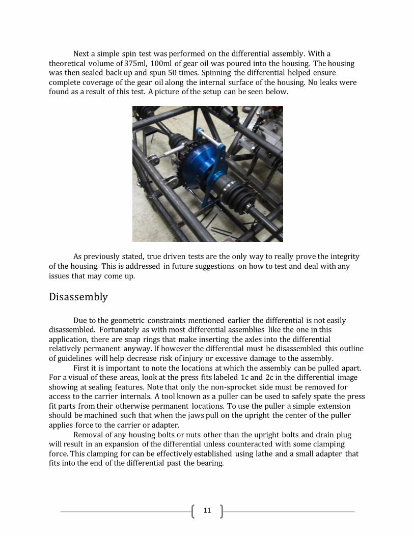
Next a simple spin test was performed on the differential assembly. With a theoretical volume of 375ml, 100ml of gear oil was poured into the housing. The housing was then sealed back up and spun 50 times. Spinning the differential helped ensure complete coverage of the gear oil along the internal surface of the housing. No leaks were found as a result of this test. A picture of the setup can be seen below.
As previously stated, true driven tests are the only way to really prove the integrity of the housing. This is addressed in future suggestions on how to test and deal with any issues that may come up.
Disassembly Due to the geometric constraints mentioned earlier the differential is not easily disassembled. Fortunately as with most differential assemblies like the one in this application, there are snap rings that make inserting the axles into the differential relatively permanent anyway. If however the differential must be disassembled this outline of guidelines will help decrease risk of injury or excessive damage to the assembly. First it is important to note the locations at which the assembly can be pulled apart. For a visual of these areas, look at the press fits labeled 1c and 2c in the differential image showing at sealing features. Note that only the non-sprocket side must be removed for access to the carrier internals. A tool known as a puller can be used to safely spate the press fit parts from their otherwise permanent locations. To use the puller a simple extension should be machined such that when the jaws pull on the upright the center of the puller applies force to the carrier or adapter. Removal of any housing bolts or nuts other than the upright bolts and drain plug will result in an expansion of the differential unless counteracted with some clamping force. This clamping for can be effectively established using lathe and a small adapter that fits into the end of the differential past the bearing.
12
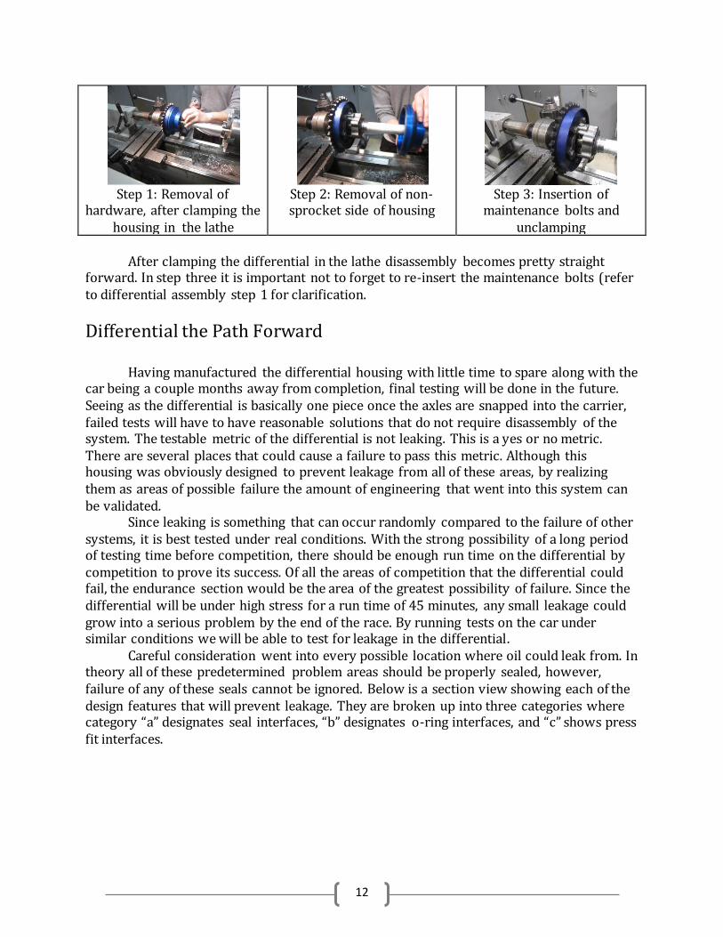
Step 1: Removal of
hardware, after clamping the housing in the lathe
Step 2: Removal of non-sprocket side of housing
Step 3: Insertion of
maintenance bolts and unclamping
After clamping the differential in the lathe disassembly becomes pretty straight forward. In step three it is important not to forget to re-insert the maintenance bolts (refer to differential assembly step 1 for clarification.
Differential the Path Forward
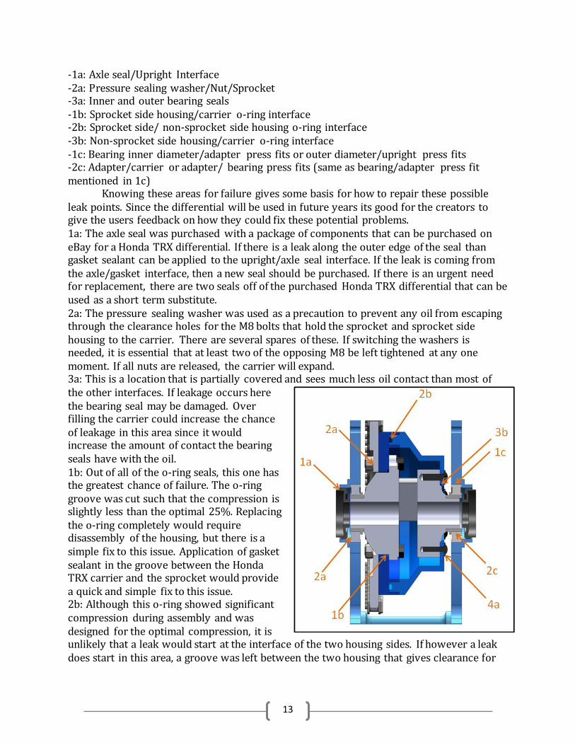
Having manufactured the differential housing with little time to spare along with the car being a couple months away from completion, final testing will be done in the future. Seeing as the differential is basically one piece once the axles are snapped into the carrier, failed tests will have to have reasonable solutions that do not require disassembly of the system. The testable metric of the differential is not leaking. This is a yes or no metric. There are several places that could cause a failure to pass this metric. Although this housing was obviously designed to prevent leakage from all of these areas, by realizing them as areas of possible failure the amount of engineering that went into this system can be validated. Since leaking is something that can occur randomly compared to the failure of other systems, it is best tested under real conditions. With the strong possibility of a long period of testing time before competition, there should be enough run time on the differential by competition to prove its success. Of all the areas of competition that the differential could fail, the endurance section would be the area of the greatest possibility of failure. Since the differential will be under high stress for a run time of 45 minutes, any small leakage could grow into a serious problem by the end of the race. By running tests on the car under similar conditions we will be able to test for leakage in the differential. Careful consideration went into every possible location where oil could leak from. In theory all of these predetermined problem areas should be properly sealed, however, failure of any of these seals cannot be ignored. Below is a section view showing each of the design features that will prevent leakage. They are broken up into three categories where category “a” designates seal interfaces, “b” designates o-ring interfaces, and “c” shows press fit interfaces.
13
-1a: Axle seal/Upright Interface -2a: Pressure sealing washer/Nut/Sprocket -3a: Inner and outer bearing seals -1b: Sprocket side housing/carrier o-ring interface -2b: Sprocket side/ non-sprocket side housing o-ring interface -3b: Non-sprocket side housing/carrier o-ring interface -1c: Bearing inner diameter/adapter press fits or outer diameter/upright press fits -2c: Adapter/carrier or adapter/ bearing press fits (same as bearing/adapter press fit mentioned in 1c) Knowing these areas for failure gives some basis for how to repair these possible leak points. Since the differential will be used in future years its good for the creators to give the users feedback on how they could fix these potential problems. 1a: The axle seal was purchased with a package of components that can be purchased on eBay for a Honda TRX differential. If there is a leak along the outer edge of the seal than gasket sealant can be applied to the upright/axle seal interface. If the leak is coming from the axle/gasket interface, then a new seal should be purchased. If there is an urgent need for replacement, there are two seals off of the purchased Honda TRX differential that can be used as a short term substitute. 2a: The pressure sealing washer was used as a precaution to prevent any oil from escaping through the clearance holes for the M8 bolts that hold the sprocket and sprocket side housing to the carrier. There are several spares of these. If switching the washers is needed, it is essential that at least two of the opposing M8 be left tightened at any one moment. If all nuts are released, the carrier will expand. 3a: This is a location that is partially covered and sees much less oil contact than most of the other interfaces. If leakage occurs here the bearing seal may be damaged. Over filling the carrier could increase the chance of leakage in this area since it would increase the amount of contact the bearing seals have with the oil. 1b: Out of all of the o-ring seals, this one has the greatest chance of failure. The o-ring groove was cut such that the compression is slightly less than the optimal 25%. Replacing the o-ring completely would require disassembly of the housing, but there is a simple fix to this issue. Application of gasket sealant in the groove between the Honda TRX carrier and the sprocket would provide a quick and simple fix to this issue. 2b: Although this o-ring showed significant compression during assembly and was designed for the optimal compression, it is unlikely that a leak would start at the interface of the two housing sides. If however a leak does start in this area, a groove was left between the two housing that gives clearance for
14
gasket sealant to be used. Fill the gap with sealant all the way around the differential to fix the leak. 3b: This is the same type of seal as 1b, but the compression was designed and machined to give the optimal 25% compression. In theory there should never be an issue with this seal, but gasket sealant can be applied in the same way as it was in 1b. 1c: If a leak occurs between the press fit of the bearing than gasket sealant should be applied first and re-tested. If the problem persists then disassembly may be required. If the leak occurs between the bearing and upright a new upright should be made to correct for the lose press fit. If the leakage is between the bearing and the adapter, then the adapter should be replaced with careful consideration to the tolerance of the press fit. 2c: Similarly to the bearing press fit, this issue may require disassembly of the housing in order to fix. Re-machining of the adapter would be necessary to correct for the lose press fit that’s causing leakage.
Axles Changes in Scope
Because the axle outer diameter is so small, we have disregarded the spring pin as a viable option.
Cutting a hole in the axle would introduce too much of a stress concentration to be effective. Further,
time and budget constraints have also contributed to our dismissal of this option.
Brief Description of Final Axle Design
The design of the axle extension has changed since phase three. After fabricating a sample axle
extension with specifications from the previous ohase, we received overwhelming feedback about the
high weight of the axle extension. In designing for reliability as the most important metric, the original
design of the axle extensions had a factor of safety in place that guaranteed the ale to hold up to the
stresses that it would be facing. This resulted in a larger outer diameter than necessary, which
increased the weight. Significant weight was shaved off both the short and long axle extensions after the
importance of low weight was increased. Now, both axle extensions have an outer diameter of 7/8”.
For detailed assembly instructions and design package, see Appendix
Metrics
Clean Interface
Target Value: Yes
Actual Value: Yes
Description: Axles fit inside the differential and are the appropriate length to create a vehicle track of
48”, and fit within the constraints of the FSAE suspension team’s specifications.
15
Cost
Target Value: Team cost less than $1000
Actual Value: $244.94 dollars (Under budget)
Description: Our final project cost came in under budget, with the axle’s only expenditure being the test
material, and two ATV axles.
Weight
Target Value: 6.9 lbs per axle (weight of previous custom axle)
Actual Value: 6.3 lbs short axle, 6.9 lbs long axle
Description: To minimize the weight, deflection had to be sacrificed. This decision was driven by
feedback from our sponsor and advisor. However, the two axles weigh a combined 0.6 lbs less than the
custom-made axles from last year.
Deflection at 20 ft-lbs
Target Value: 0.68 Degrees (Deflection of Custom Axles)
Actual Value: 0.61 Degrees in short axle, 0.82 degrees in long axle
Description: At normal driving conditions, the engine will produce a maximum of 20 ft-lbs of torque in
each axle. To most efficiently transfer power to the wheels, we want to minimize deflection. Our initial
goal was to match the deflections of the short and long axle, but based on feedback from our sponsor
and advisor, the increase in weight was not worth matching deflections so precisely. With less than half
of a degree of deflection difference between the two axles, it is insignificant to increase the amount of
material to match the deflections compared to the weight savings gained by using the shorter diameter
extensions.
Allowable Static Torque
Target Value: 165 ft-lbs
Actual Value: 335 ft-lbs
Description: Test axles were made with similar material and tested in torsion, and the allowable torque
before failure was found to be approximately 335 ft-lbs before the weld points gave out and the axle
extension slipped relative to the ATV Axles
16
Validation
Experiment
In order to experiment on the design of the new axles, we will have to test a similar axle assembly of
pieces in torsion. Due to the budget constraints, the test materials will be made of mild steel, while the
ATV Axles are high carbon, hardened steel, and the tube extensions are heat treated 4130 Chromoly
Steel. These test results will hold true for the final design.
This experiment will focus on quantifying the amount of torque that can be applied through the axle
without making the axle extension slip, but after the experiment, we will be able to determine the weld
strength, failure modes, maximum allowable torque through the shaft, and accuracy of testing. Five test
setups will be created and tested, each testing a specific design parameter of the axle extension.
1. Short extension, press fit only 2. Short extension, press fit and spot welded (x2) 3. Long extension (same OD as short extension) press fit and spot welded 4. Long extension (different OD as short extension to match torsional deflection) press fit and spot
welded.
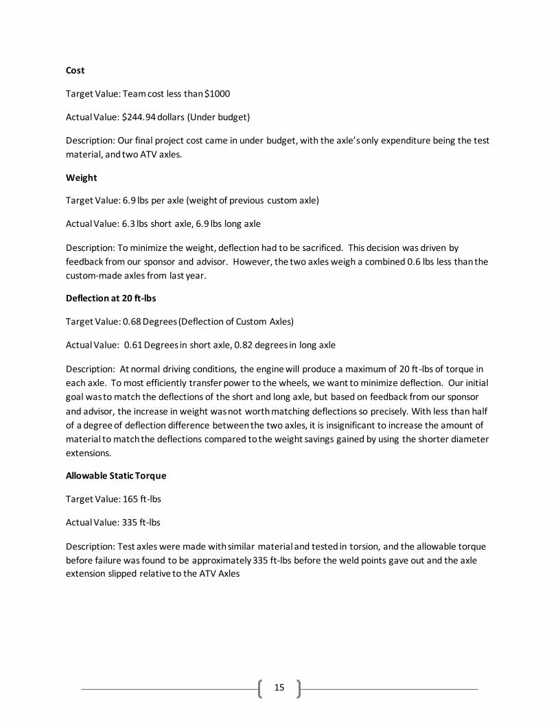
The test apparatus, with one of the test
specimens being tested, can be shown in
picture right. The setup requires a 1/2”
steel plate to be fixed to the Instron
machine using C-clamps, which creates a
platform for the test apparatus. The test
apparatus consists of a “Square Block” and
“Lever Arm” which fix the test axle in
place, and a circle block, which lets the
axle spin
through
it. When
the
Instron machine moves down, tension is applied to the wire rope,
which applies a torque (at the distance of the lever arm, which is 12”)
on the test axle specimen.
The picture to the leftshows the front and back views of the “Square
Block”, which is a piece of 2” x 4” steel with a ¾” Drive Socket press fit
and welded into it. The test axle specimen fits securely in the square
and the Square Block is fixed to the testing apparatus using C-Clamps.
To make sure the components are fixed, squares were cut into each
17
side of the ATV axle extension to fix them to the testing apparatus.
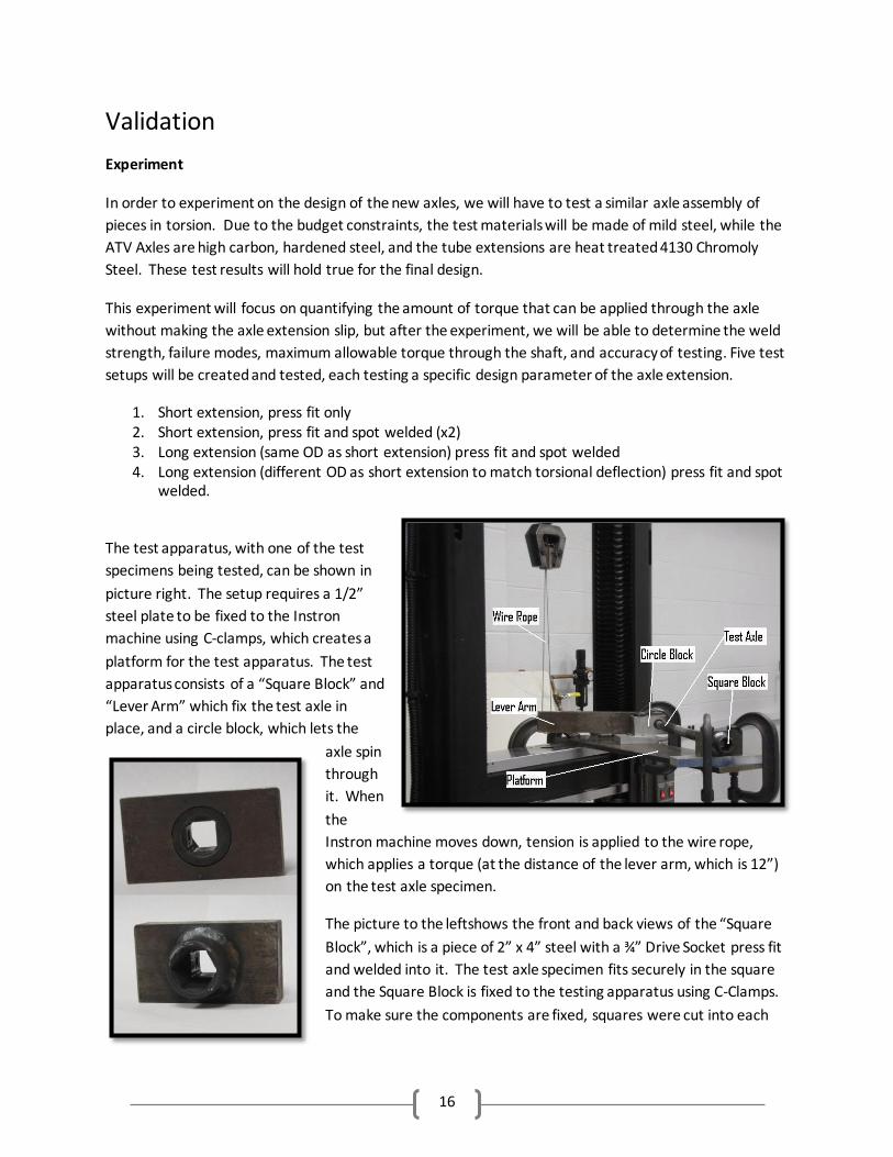
Each test extension will have two shafts press fit into both sides, which represent the ATV axle. We will
use thermal expansion in order to make sure the axle shafts will slide smoothly into the extension during
the press fit. In order to guarantee the 0.0013” press fit that is necessary, the extension will be heated
to no more than 727 F (to conserve the heat
treatment and ensure that the eutectic temperature
is not reached), and the axle shafts will be cooled in
a freezer to approximately 50 F, and the
components will slip easily in to each other. This
process will be repeated with the final axle
components. Figure right shows one of the
specimens that was tested.
Results
The results of the experiment showed the allowable
torque through the axles to be much higher than
what we were aiming for. Unfortunately, the weld strength was not able to be calculated, because of
complications with one of the test specimens. However, the other information that was needed is
calculated, and the axles are able to be validated
for use in the design.
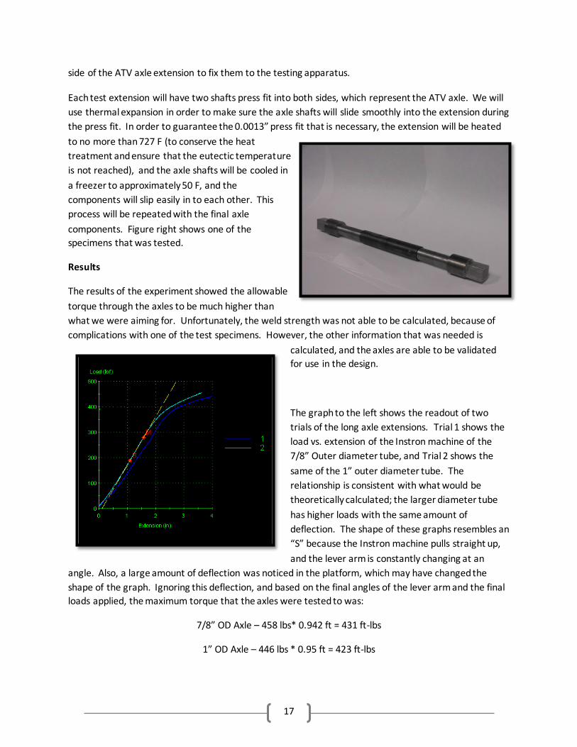
The graph to the left shows the readout of two
trials of the long axle extensions. Trial 1 shows the
load vs. extension of the Instron machine of the
7/8” Outer diameter tube, and Trial 2 shows the
same of the 1” outer diameter tube. The
relationship is consistent with what would be
theoretically calculated; the larger diameter tube
has higher loads with the same amount of
deflection. The shape of these graphs resembles an
“S” because the Instron machine pulls straight up,
and the lever arm is constantly changing at an
angle. Also, a large amount of deflection was noticed in the platform, which may have changed the
shape of the graph. Ignoring this deflection, and based on the final angles of the lever arm and the final
loads applied, the maximum torque that the axles were tested to was:
7/8” OD Axle – 458 lbs* 0.942 ft = 431 ft-lbs
1” OD Axle – 446 lbs * 0.95 ft = 423 ft-lbs
18
The tests were stopped at these points due to the fact that an unsafe amount of deflection was seen in
the platform. Therefore, we cannot draw too many conclusions from this data about the actual
performance of the axle.
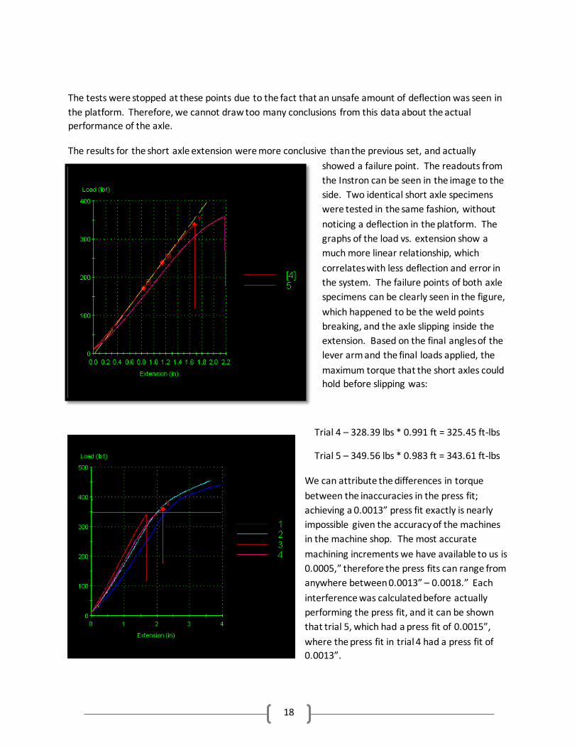
The results for the short axle extension were more conclusive than the previous set, and actually
showed a failure point. The readouts from
the Instron can be seen in the image to the
side. Two identical short axle specimens
were tested in the same fashion, without
noticing a deflection in the platform. The
graphs of the load vs. extension show a
much more linear relationship, which
correlates with less deflection and error in
the system. The failure points of both axle
specimens can be clearly seen in the figure,
which happened to be the weld points
breaking, and the axle slipping inside the
extension. Based on the final angles of the
lever arm and the final loads applied, the
maximum torque that the short axles could
hold before slipping was:
Trial 4 – 328.39 lbs * 0.991 ft = 325.45 ft-lbs
Trial 5 – 349.56 lbs * 0.983 ft = 343.61 ft-lbs
We can attribute the differences in torque
between the inaccuracies in the press fit;
achieving a 0.0013” press fit exactly is nearly
impossible given the accuracy of the machines
in the machine shop. The most accurate
machining increments we have available to us is
0.0005,” therefore the press fits can range from
anywhere between 0.0013” – 0.0018.” Each
interference was calculated before actually
performing the press fit, and it can be shown
that trial 5, which had a press fit of 0.0015”,
where the press fit in trial 4 had a press fit of
0.0013”.
19
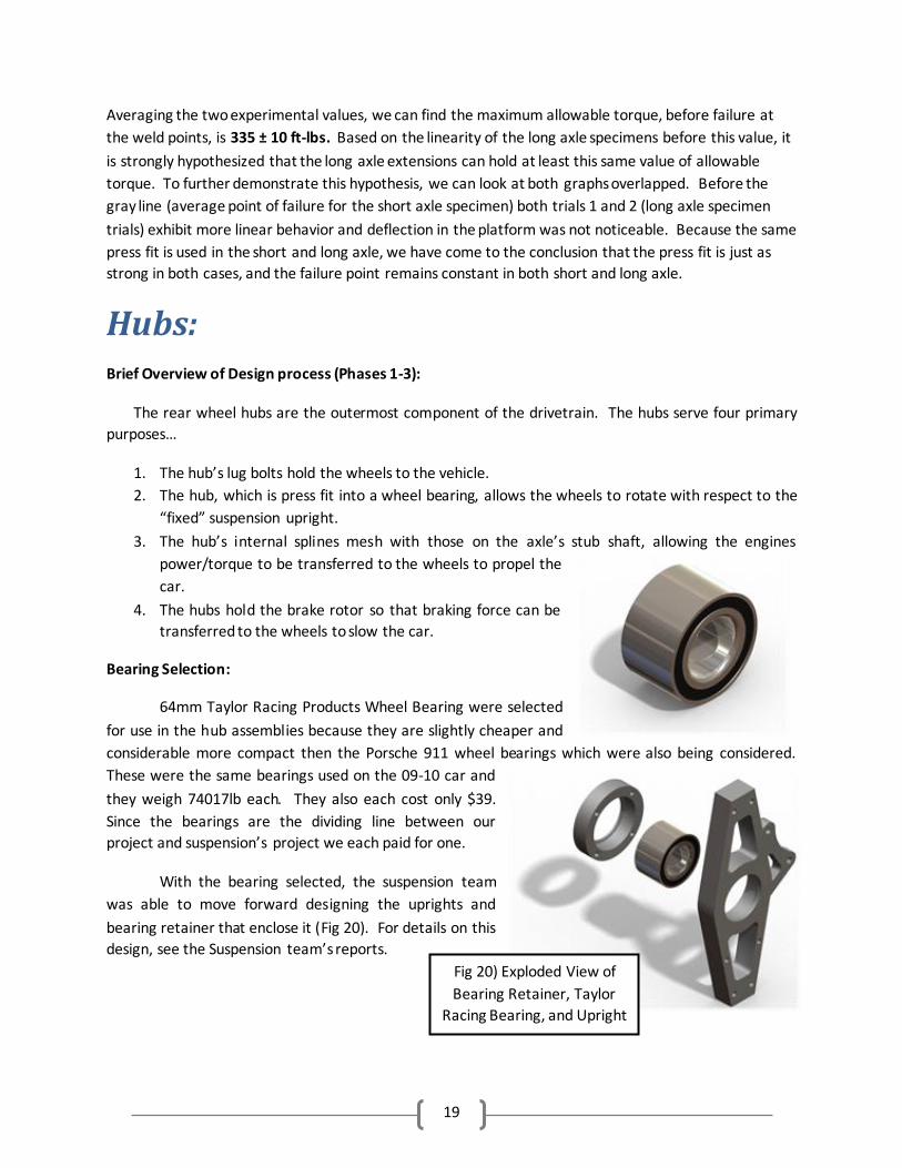
Fig 20) Exploded View of
Bearing Retainer, Taylor
Racing Bearing, and Upright
Averaging the two experimental values, we can find the maximum allowable torque, before failure at
the weld points, is 335 ± 10 ft-lbs. Based on the linearity of the long axle specimens before this value, it
is strongly hypothesized that the long axle extensions can hold at least this same value of allowable
torque. To further demonstrate this hypothesis, we can look at both graphs overlapped. Before the
gray line (average point of failure for the short axle specimen) both trials 1 and 2 (long axle specimen
trials) exhibit more linear behavior and deflection in the platform was not noticeable. Because the same
press fit is used in the short and long axle, we have come to the conclusion that the press fit is just as
strong in both cases, and the failure point remains constant in both short and long axle.
Hubs: Brief Overview of Design process (Phases 1-3):
The rear wheel hubs are the outermost component of the drivetrain. The hubs serve four primary
purposes…
1. The hub’s lug bolts hold the wheels to the vehicle.
2. The hub, which is press fit into a wheel bearing, allows the wheels to rotate with respect to the
“fixed” suspension upright.
3. The hub’s internal splines mesh with those on the axle’s stub shaft, allowing the engines
power/torque to be transferred to the wheels to propel the
car.
4. The hubs hold the brake rotor so that braking force can be
transferred to the wheels to slow the car.
Bearing Selection:
64mm Taylor Racing Products Wheel Bearing were selected
for use in the hub assemblies because they are slightly cheaper and
considerable more compact then the Porsche 911 wheel bearings which were also being considered.
These were the same bearings used on the 09-10 car and
they weigh 74017lb each. They also each cost only $39.
Since the bearings are the dividing line between our
project and suspension’s project we each paid for one.
With the bearing selected, the suspension team
was able to move forward designing the uprights and
bearing retainer that enclose it (Fig 20). For details on this
design, see the Suspension team’s reports.
20
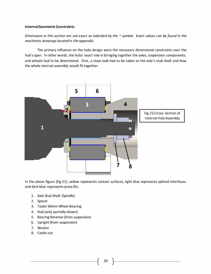
Fig 21) Cross Section of
Internal Hub Assembly
Internal Geometric Constraints
Dimensions in this section are not exact as indicated by the ~ symbol. Exact values can be found in the
machinists drawings located in the appendix.
The primary influence on the hubs design were the necessary dimensional constraints over the
hub’s span. In other words, the hubs’ exact role in bringing together the axles, suspension components,
and wheels had to be determined. First, a close look had to be taken at the axle’s stub shaft and how
the whole internal assembly would fit together.
In the above figure (Fig 21): yellow represents contact surfaces, light blue represents splined interfaces,
and dark blue represents press fits.
1. Axle Stub Shaft (Spindle)
2. Spacer
3. Taylor 64mm Wheel Bearing
4. Hub (only partially shown)
5. Bearing Retainer (from suspension)
6. Upright (from suspension)
7. Washer
8. Castle nut
21
There are several key things to note in this assembly. First of all, the bearing is the only thing in
contact with, and the bearing exterior is effectively one with, suspension’s upright and bearing retainer.
Next, notice the hub is press fit into the bearing interior to allow for rotation and interfaces with the
stub shaft via splining. This allows to allow torque to be transferred from the axle to the hub. Finally,
note that spacer (2) allows the bearing interior to be effectively sandwiched between the stub shaft and
hub when the castle nut (8) is installed. This eliminates any chance of force transmitted down the axle
overcoming the friction from the hub’s press fit and sliding everything axially out of the bearing.
Without the spacer (2), the radius on the bearing would awkwardly contact the point at the bottom of
the small chamfer on the stub shaft (red dots on figure).
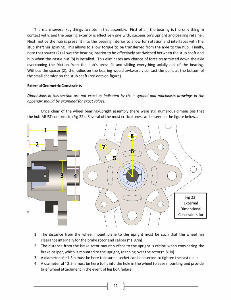
External Geometric Constraints
Dimensions in this section are not exact as indicated by the ~ symbol and machinists drawings in the
appendix should be examined for exact values.
Once clear of the wheel bearing/upright assembly there were still numerous dimensions that
the hub MUST conform to (Fig 22). Several of the most critical ones can be seen in the figure below…
1. The distance from the wheel mount plane to the upright must be such that the wheel has
clearance internally for the brake rotor and caliper (~1.87in)
2. The distance from the brake rotor mount surface to the upright is critical when considering the
brake caliper, which is mounted to the upright, reaching over the rotor (~.81in)
3. A diameter of ~1.5in must be here to insure a socket can be inserted to tighten the castle nut
4. A diameter of ~2.5in must be here to fit into the hole in the wheel to ease mounting and provide
brief wheel attachment in the event of lug bolt failure
Fig 22)
External
Dimensional
Constraints for
Hub
22
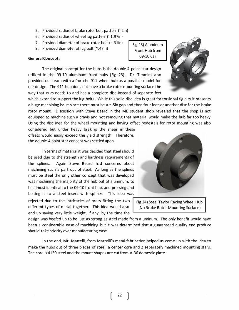
Fig 23) Aluminum
Front Hub from
09-10 Car
Fig 24) Steel Taylor Racing Wheel Hub
(No Brake Rotor Mounting Surface)
5. Provided radius of brake rotor bolt pattern (~2in)
6. Provided radius of wheel lug pattern (~1.97in)
7. Provided diameter of brake rotor bolt (~.31in)
8. Provided diameter of lug bolt (~.47in)
General Concept:
The original concept for the hubs is the double 4 point star design
utilized in the 09-10 aluminum front hubs (Fig 23). Dr. Timmins also
provided our team with a Porsche 911 wheel hub as a possible model for
our design. The 911 hub does not have a brake rotor mounting surface the
way that ours needs to and has a complete disc instead of separate feet
which extend to support the lug bolts. While this solid disc idea is great for torsional rigidity it presents
a huge machining issue since there must be a ~.5in gap and then four feet or another disc for the brake
rotor mount. Discussion with Steve Beard in the ME student shop revealed that the shop is not
equipped to machine such a cravis and not removing that material would make the hub far too heavy.
Using the disc idea for the wheel mounting and having offset pedestals for rotor mounting was also
considered but under heavy braking the shear in these
offsets would easily exceed the yield strength. Therefore,
the double 4 point star concept was settled upon.
In terms of material it was decided that steel should
be used due to the strength and hardness requirements of
the splines. Again Steve Beard had concerns about
machining such a part out of steel. As long as the splines
must be steel the only other concept that was developed
was machining the majority of the hub out of aluminum, to
be almost identical to the 09-10 front hub, and pressing and
bolting it to a steel insert with splines. This idea was
rejected due to the intricacies of press fitting the two
different types of metal together. This idea would also
end up saving very little weight, if any, by the time the
design was beefed up to be just as strong as steel made from aluminum. The only benefit would have
been a considerable ease of machining but it was determined that a guaranteed quality end produce
should take priority over manufacturing ease.
In the end, Mr. Martelli, from Martelli’s metal fabrication helped us come up with the idea to
make the hubs out of three pieces of steel; a center core and 2 separately machined mounting stars.
The core is 4130 steel and the mount shapes are cut from A-36 domestic plate.
23
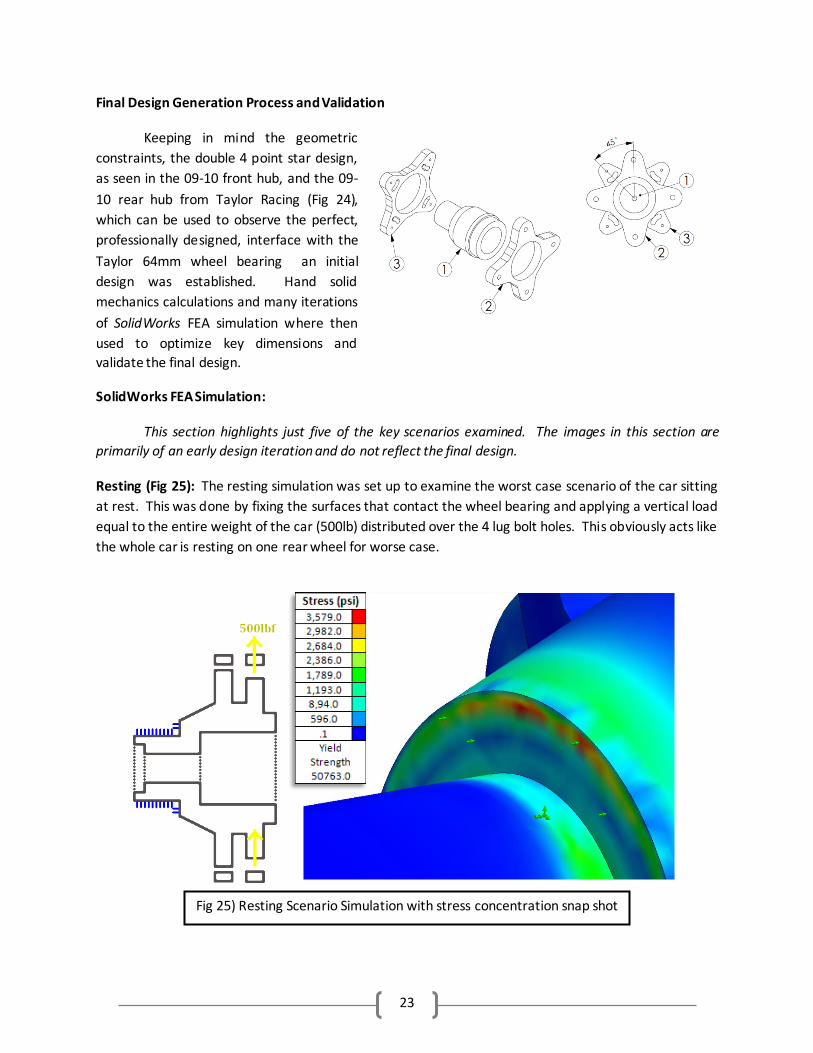
Final Design Generation Process and Validation
Keeping in mind the geometric
constraints, the double 4 point star design,
as seen in the 09-10 front hub, and the 09-
10 rear hub from Taylor Racing (Fig 24),
which can be used to observe the perfect,
professionally designed, interface with the
Taylor 64mm wheel bearing an initial
design was established. Hand solid
mechanics calculations and many iterations
of SolidWorks FEA simulation where then
used to optimize key dimensions and
validate the final design.
SolidWorks FEA Simulation:
This section highlights just five of the key scenarios examined. The images in this section are
primarily of an early design iteration and do not reflect the final design.
Resting (Fig 25): The resting simulation was set up to examine the worst case scenario of the car sitting
at rest. This was done by fixing the surfaces that contact the wheel bearing and applying a vertical load
equal to the entire weight of the car (500lb) distributed over the 4 lug bolt holes. This obviously acts like
the whole car is resting on one rear wheel for worse case.
Fig 25) Resting Scenario Simulation with stress concentration snap shot
24
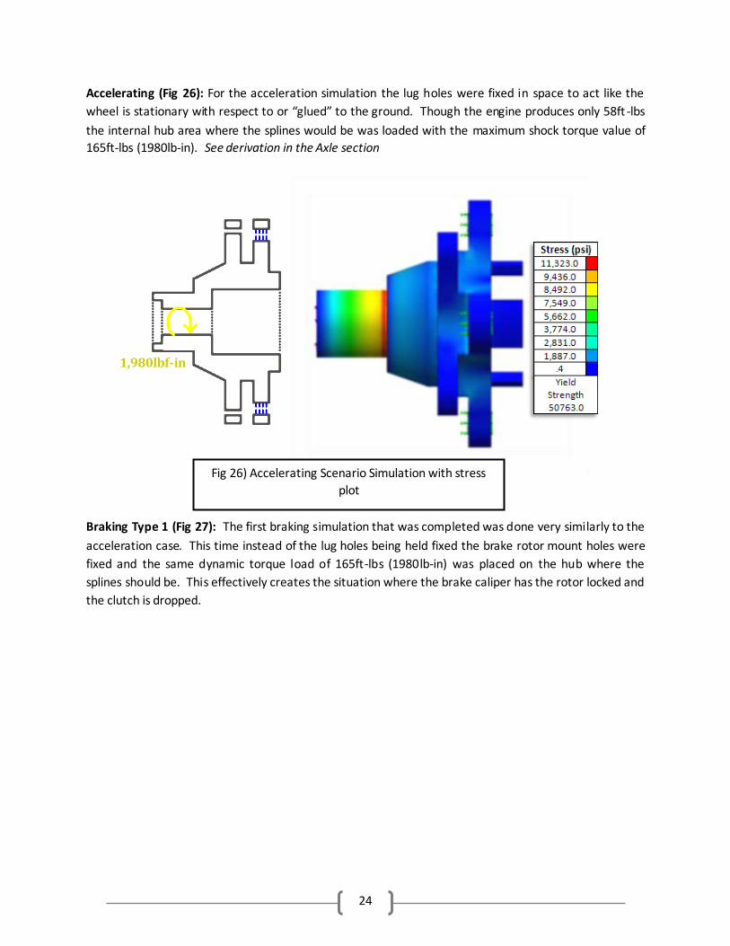
Accelerating (Fig 26): For the acceleration simulation the lug holes were fixed in space to act like the
wheel is stationary with respect to or “glued” to the ground. Though the engine produces only 58ft -lbs
the internal hub area where the splines would be was loaded with the maximum shock torque value of
165ft-lbs (1980lb-in). See derivation in the Axle section
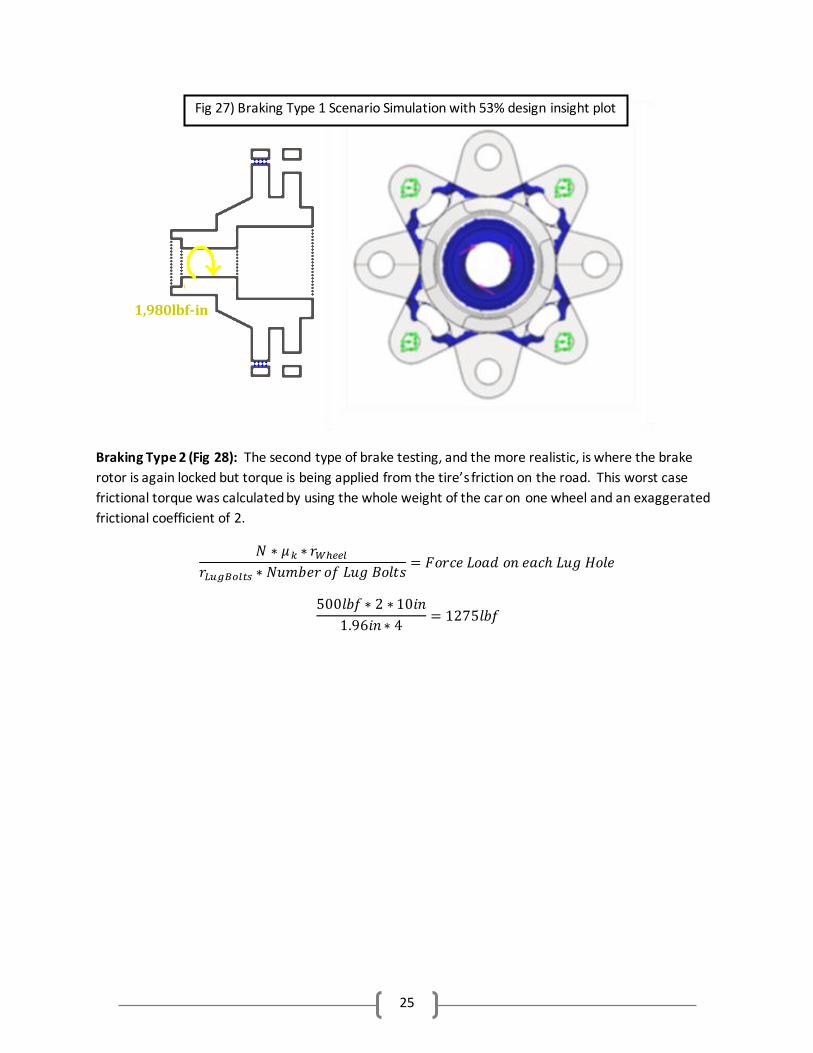
Braking Type 1 (Fig 27): The first braking simulation that was completed was done very similarly to the
acceleration case. This time instead of the lug holes being held fixed the brake rotor mount holes were
fixed and the same dynamic torque load of 165ft-lbs (1980lb-in) was placed on the hub where the
splines should be. This effectively creates the situation where the brake caliper has the rotor locked and
the clutch is dropped.
Fig 26) Accelerating Scenario Simulation with stress
plot
1,980lbf-in
25
Braking Type 2 (Fig 28): The second type of brake testing, and the more realistic, is where the brake
rotor is again locked but torque is being applied from the tire’s friction on the road. This worst case
frictional torque was calculated by using the whole weight of the car on one wheel and an exaggerated
frictional coefficient of 2.
Fig 27) Braking Type 1 Scenario Simulation with 53% design insight plot
1,980lbf-in
26
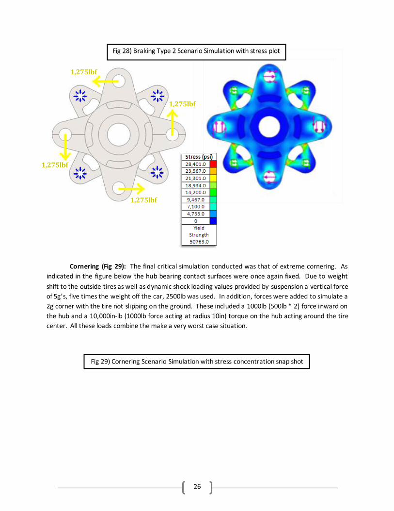
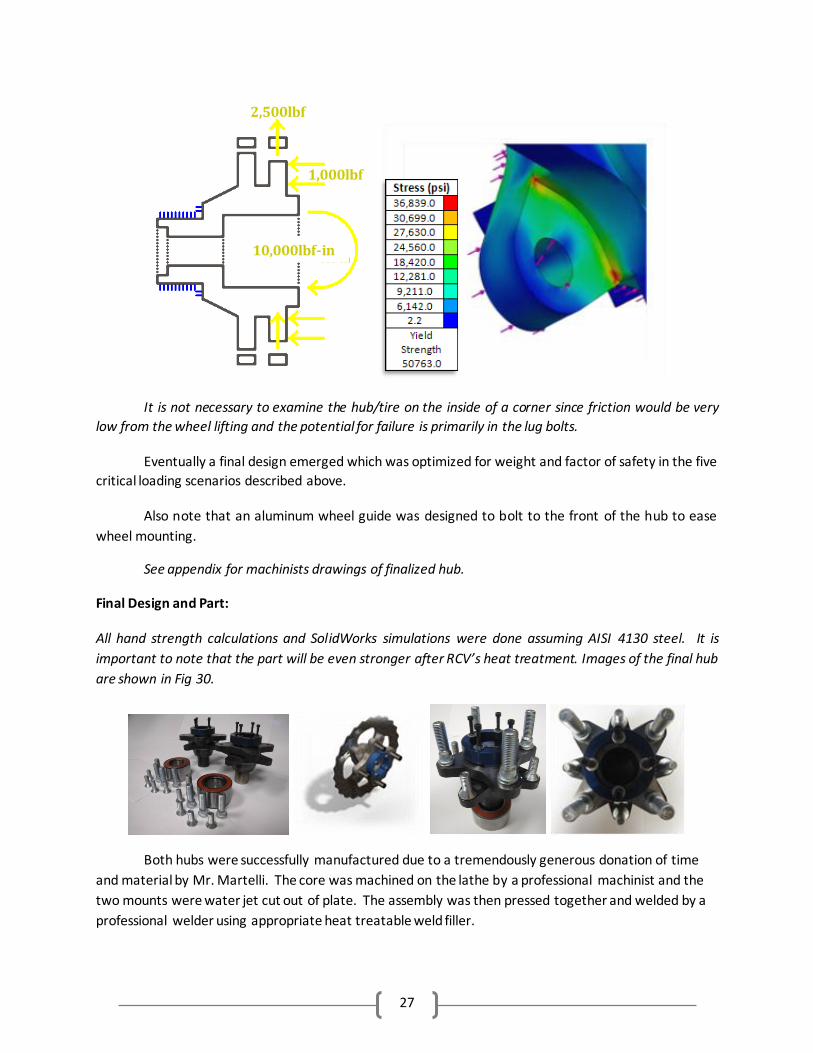
Cornering (Fig 29): The final critical simulation conducted was that of extreme cornering. As
indicated in the figure below the hub bearing contact surfaces were once again fixed. Due to weight
shift to the outside tires as well as dynamic shock loading values provided by suspension a vertical force
of 5g’s, five times the weight off the car, 2500lb was used. In addition, forces were added to simulate a
2g corner with the tire not slipping on the ground. These included a 1000lb (500lb * 2) force inward on
the hub and a 10,000in-lb (1000lb force acting at radius 10in) torque on the hub acting around the tire
center. All these loads combine the make a very worst case situation.
1,275lbf
1,275lbf
1,275lbf
1,275lbf
Fig 28) Braking Type 2 Scenario Simulation with stress plot
Fig 29) Cornering Scenario Simulation with stress concentration snap shot
27
It is not necessary to examine the hub/tire on the inside of a corner since friction would be very
low from the wheel lifting and the potential for failure is primarily in the lug bolts.
Eventually a final design emerged which was optimized for weight and factor of safety in the five
critical loading scenarios described above.
Also note that an aluminum wheel guide was designed to bolt to the front of the hub to ease
wheel mounting.
See appendix for machinists drawings of finalized hub.
Final Design and Part:
All hand strength calculations and SolidWorks simulations were done assuming AISI 4130 steel. It is
important to note that the part will be even stronger after RCV’s heat treatment. Images of the final hub
are shown in Fig 30.
Both hubs were successfully manufactured due to a tremendously generous donation of time
and material by Mr. Martelli. The core was machined on the lathe by a professional machinist and the
two mounts were water jet cut out of plate. The assembly was then pressed together and welded by a
professional welder using appropriate heat treatable weld filler.
2,500lbf
1,000lbf
10,000lbf-in
28
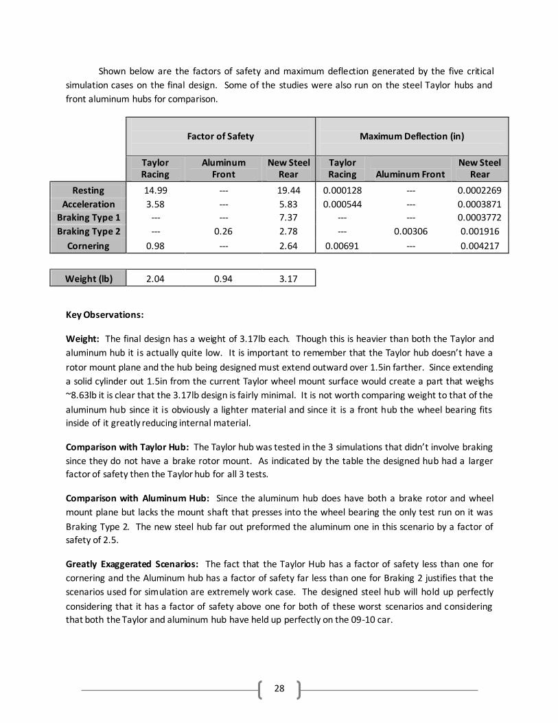
Shown below are the factors of safety and maximum deflection generated by the five critical
simulation cases on the final design. Some of the studies were also run on the steel Taylor hubs and
front aluminum hubs for comparison.
Factor of Safety
Maximum Deflection (in)
Taylor Racing
Aluminum Front
New Steel Rear
Taylor Racing Aluminum Front
New Steel Rear
Resting 14.99 --- 19.44 0.000128 --- 0.0002269
Acceleration 3.58 --- 5.83 0.000544 --- 0.0003871
Braking Type 1 --- --- 7.37 --- --- 0.0003772
Braking Type 2 --- 0.26 2.78 --- 0.00306 0.001916
Cornering 0.98 --- 2.64 0.00691 --- 0.004217
Weight (lb) 2.04 0.94 3.17
Key Observations:
Weight: The final design has a weight of 3.17lb each. Though this is heavier than both the Taylor and
aluminum hub it is actually quite low. It is important to remember that the Taylor hub doesn’t have a
rotor mount plane and the hub being designed must extend outward over 1.5in farther. Since extending
a solid cylinder out 1.5in from the current Taylor wheel mount surface would create a part that weighs
~8.63lb it is clear that the 3.17lb design is fairly minimal. It is not worth comparing weight to that of the
aluminum hub since it is obviously a lighter material and since it is a front hub the wheel bearing fits
inside of it greatly reducing internal material.
Comparison with Taylor Hub: The Taylor hub was tested in the 3 simulations that didn’t involve braking
since they do not have a brake rotor mount. As indicated by the table the designed hub had a larger
factor of safety then the Taylor hub for all 3 tests.
Comparison with Aluminum Hub: Since the aluminum hub does have both a brake rotor and wheel
mount plane but lacks the mount shaft that presses into the wheel bearing the only test run on it was
Braking Type 2. The new steel hub far out preformed the aluminum one in this scenario by a factor of
safety of 2.5.
Greatly Exaggerated Scenarios: The fact that the Taylor Hub has a factor of safety less than one for
cornering and the Aluminum hub has a factor of safety far less than one for Braking 2 justifies that the
scenarios used for simulation are extremely work case. The designed steel hub will hold up perfectly
considering that it has a factor of safety above one for both of these worst scenarios and considering
that both the Taylor and aluminum hub have held up perfectly on the 09-10 car.
29
Fatigue:
Full fatigue analysis was conducted on the two scenarios with the lowest factors of safety,
braking type 2 and cornering, to determine the lifespan of the part under these loadings. The
simulations were set up to run the 2 cases in a fully reversed mode to portray hub rotation until part
failure based on SolidWorks S-N Curves derived from Young’s modulus.
If the car was driven in the cornering scenario for 28hrs it would fail from fatigue
If the car was driven in the braking type 2 scenario for 33hrs it would fail from fatigue
These results are fine since the car is only driven for around 30 hours over the course of the
year/season and little if any of that time will be spent in these very extreme loading situations.
Successful Cost Minimization:
Only $130 for the pair after splining and heat treating due to Mr. Martelli’s generous donations
Current Status:
The hubs are the only component of our project which did not end up properly installed on the
final car. This is due to the fact that the broaching and heat treating procedure has at least a 2 week
lead time and Dr. Timmins advised us that it would be best to not send the hubs away but instead keep
them to show at the presentation.
Finish Machining:
Once the hubs were received from Martelli’s there was a bit of machining that had to be done
to finish the pieces.
1. The wheel mount surface had to be flattened on the lathe 2. Material had to be taken off the brake rotor mount surface to ensure proper dimensioning
between the wheel and brake mount planes 3. The lug bolt holes had to be boarded out for a tight permanent press fit 4. The brake rotor bolt holes had to be drilled larger and tapped 5. The holes to bolt the aluminum wheel guide to had to be drilled, tapped, and counter board
Path Forward:
With senior design drawing to a close the hubs will promptly be finished. A good bit of the finish
machining described above has already been done but there is a little to finish and that will be the first
order of business. Next, the hubs will promptly be sent away for broaching and heat treating. When
they return, around the beginning of winter session, all threads will be re-tapped, as slight warping may
have occurred from heat treating. The lug bolts and wheel bearing can then be pressed in place and the
unit can be assembled in the uprights from suspension. Once installed on the car the hubs performance
and integrity can be observed.
30
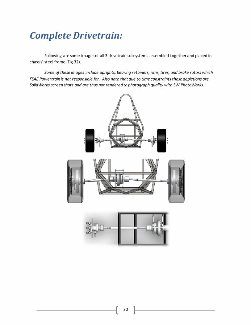
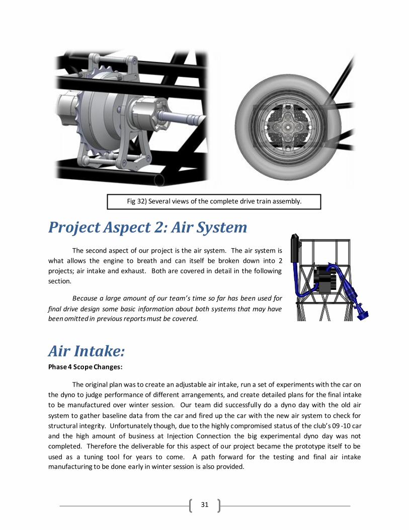
Complete Drivetrain:
Following are some images of all 3 drivetrain subsystems assembled together and placed in
chassis’ steel frame (Fig 32).
Some of these images include uprights, bearing retainers, rims, tires, and brake rotors which
FSAE Powertrain is not responsible for. Also note that due to time constraints these depictions are
SolidWorks screen shots and are thus not rendered to photograph quality with SW PhotoWorks.
31
Project Aspect 2: Air System
The second aspect of our project is the air system. The air system is
what allows the engine to breath and can itself be broken down into 2
projects; air intake and exhaust. Both are covered in detail in the following
section.
Because a large amount of our team’s time so far has been used for
final drive design some basic information about both systems that may have
been omitted in previous reports must be covered.
Air Intake: Phase 4 Scope Changes:
The original plan was to create an adjustable air intake, run a set of experiments with the car on
the dyno to judge performance of different arrangements, and create detailed plans for the final intake
to be manufactured over winter session. Our team did successfully do a dyno day with the old air
system to gather baseline data from the car and fired up the car with the new air system to check for
structural integrity. Unfortunately though, due to the highly compromised status of the club’s 09 -10 car
and the high amount of business at Injection Connection the big experimental dyno day was not
completed. Therefore the deliverable for this aspect of our project became the prototype itself to be
used as a tuning tool for years to come. A path forward for the testing and final air intake
manufacturing to be done early in winter session is also provided.
Fig 32) Several views of the complete drive train assembly.
32
Overview of Phases 1-3:
All the air that enters the engine is delivered via the air intake. An effectively designed and
optimized air intake can improve the volumetric efficiency of any engine by up to ~10% over a missing or
poorly designed intake which can actually be highly detrimental to performance.
Constraints:
For engine to function…
Must have an air filtration component of some kind to clean the inlet air and prevent fouling of
engine components
Must have a throttle body to control the amount of air able to flow into the engine
Must have fuel injector port from where the fuel injector (FI) can spray fuel
Must have a short “runner” tube where the fuel injector port is located some distance from the
engine valves to allow the fuel to mix with the flowing air
Must have a small “Fuel Pressure Regulator Local FI Ambient Reference Point” for a hose from
the pressure regulator to attach to
Must have a throttle position sensor and mass flow sensor to feed data to the on board ECU unit
(only one of these at a time, used along with rpm readings, is necessary but we must provide
ports for both)
Must mount securely to the engine head with gasket to prevent air leakage
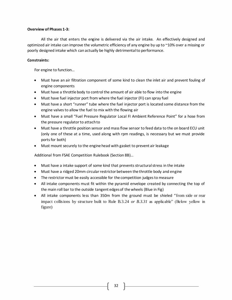
Additional from FSAE Competition Rulebook (Section 8B)…
Must have a intake support of some kind that prevents structural stress in the intake
Must have a ridged 20mm circular restrictor between the throttle body and engine
The restrictor must be easily accessible for the competition judges to measure
All intake components must fit within the pyramid envelope created by connecting the top of
the main roll bar to the outside tangent edges of the wheels (Blue in Fig)
All intake components less than 350m from the ground must be shieled “from side or rear
impact collis ions by structure built to Rule B.3.24 or B.3.31 as applicable” (Below yellow in
figure)
33
Additional from Mr. Shwarz…
Must have a velocity stack/bellmouth that smoothly transitions from the air filter to the throttle
body
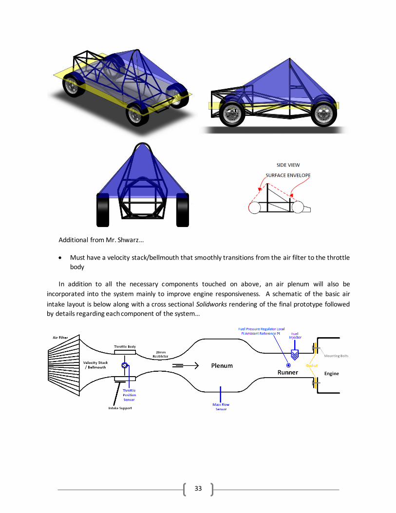
In addition to all the necessary components touched on above, an air plenum will also be
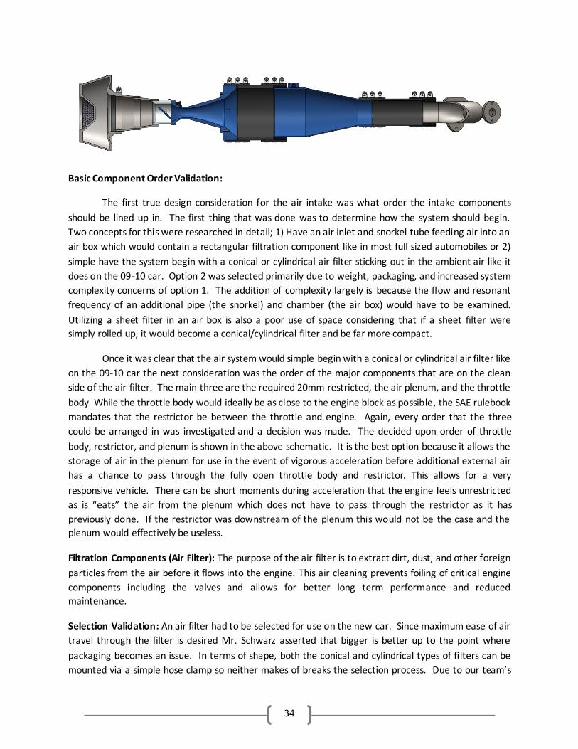
incorporated into the system mainly to improve engine responsiveness. A schematic of the basic air
intake layout is below along with a cross sectional Solidworks rendering of the final prototype followed
by details regarding each component of the system…
34
Basic Component Order Validation:
The first true design consideration for the air intake was what order the intake components
should be lined up in. The first thing that was done was to determine how the system should begin.
Two concepts for this were researched in detail; 1) Have an air inlet and snorkel tube feeding air into an
air box which would contain a rectangular filtration component like in most full sized automobiles or 2)
simple have the system begin with a conical or cylindrical air filter sticking out in the ambient air like it
does on the 09-10 car. Option 2 was selected primarily due to weight, packaging, and increased system
complexity concerns of option 1. The addition of complexity largely is because the flow and resonant
frequency of an additional pipe (the snorkel) and chamber (the air box) would have to be examined.
Utilizing a sheet filter in an air box is also a poor use of space considering that if a sheet filter were
simply rolled up, it would become a conical/cylindrical filter and be far more compact.
Once it was clear that the air system would simple begin with a conical or cylindrical air filter like
on the 09-10 car the next consideration was the order of the major components that are on the clean
side of the air filter. The main three are the required 20mm restricted, the air plenum, and the throttle
body. While the throttle body would ideally be as close to the engine block as possible, the SAE rulebook
mandates that the restrictor be between the throttle and engine. Again, every order that the three
could be arranged in was investigated and a decision was made. The decided upon order of throttle
body, restrictor, and plenum is shown in the above schematic. It is the best option because it allows the
storage of air in the plenum for use in the event of vigorous acceleration before additional external air
has a chance to pass through the fully open throttle body and restrictor. This allows for a very
responsive vehicle. There can be short moments during acceleration that the engine feels unrestricted
as is “eats” the air from the plenum which does not have to pass through the restrictor as it has
previously done. If the restrictor was downstream of the plenum this would not be the case and the
plenum would effectively be useless.
Filtration Components (Air Filter): The purpose of the air filter is to extract dirt, dust, and other foreign
particles from the air before it flows into the engine. This air cleaning prevents foiling of critical engine
components including the valves and allows for better long term performance and reduced
maintenance.
Selection Validation: An air filter had to be selected for use on the new car. Since maximum ease of air
travel through the filter is desired Mr. Schwarz asserted that bigger is better up to the point where
packaging becomes an issue. In terms of shape, both the conical and cylindrical types of filters can be
mounted via a simple hose clamp so neither makes of breaks the selection process. Due to our team’s
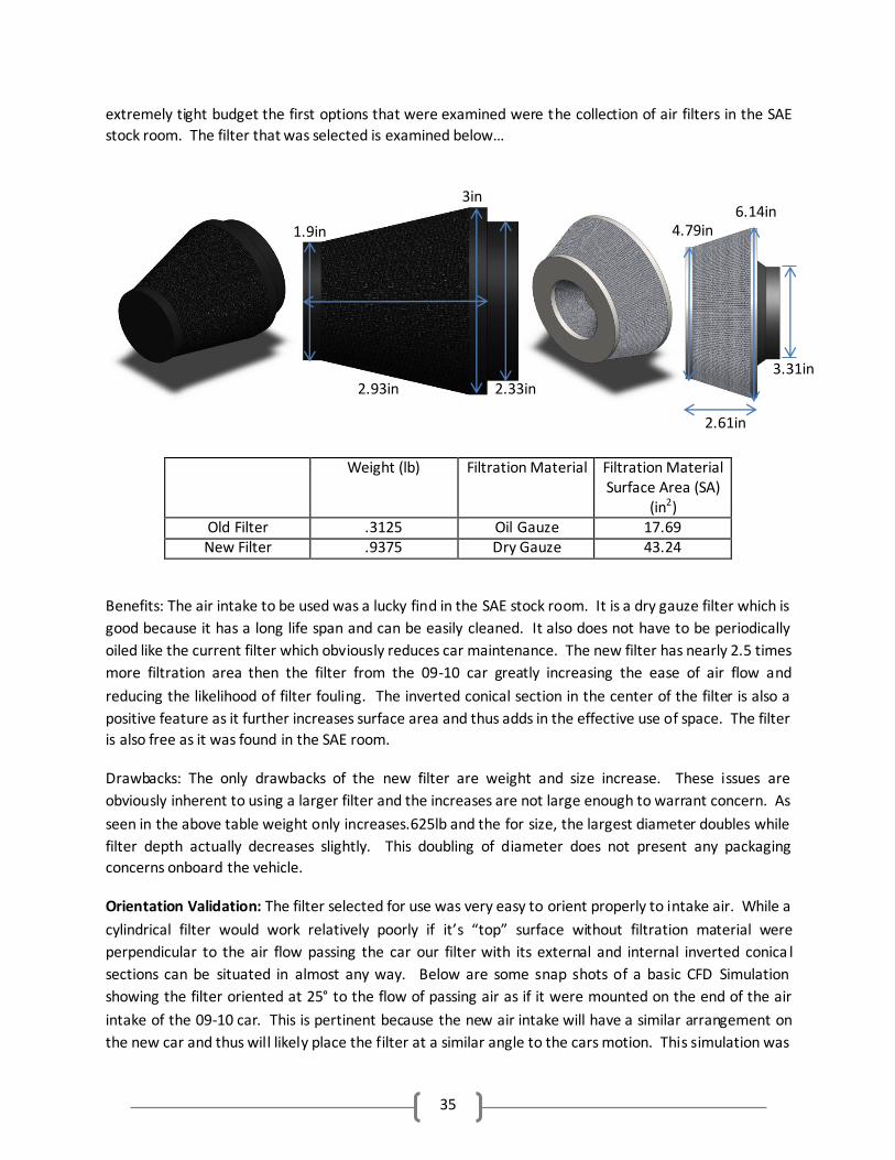
35
extremely tight budget the first options that were examined were the collection of air filters in the SAE
stock room. The filter that was selected is examined below…
Weight (lb) Filtration Material Filtration Material Surface Area (SA)
(in2) Old Filter .3125 Oil Gauze 17.69 New Filter .9375 Dry Gauze 43.24
Benefits: The air intake to be used was a lucky find in the SAE stock room. It is a dry gauze filter which is
good because it has a long life span and can be easily cleaned. It also does not have to be periodically
oiled like the current filter which obviously reduces car maintenance. The new filter has nearly 2.5 times
more filtration area then the filter from the 09-10 car greatly increasing the ease of air flow and
reducing the likelihood of filter fouling. The inverted conical section in the center of the filter is also a
positive feature as it further increases surface area and thus adds in the effective use of space. The filter
is also free as it was found in the SAE room.
Drawbacks: The only drawbacks of the new filter are weight and size increase. These issues are
obviously inherent to using a larger filter and the increases are not large enough to warrant concern. As
seen in the above table weight only increases.625lb and the for size, the largest diameter doubles while
filter depth actually decreases slightly. This doubling of diameter does not present any packaging
concerns onboard the vehicle.
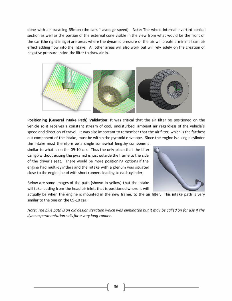
Orientation Validation: The filter selected for use was very easy to orient properly to intake air. While a
cylindrical filter would work relatively poorly if it’s “top” surface without filtration material were
perpendicular to the air flow passing the car our filter with its external and internal inverted conica l
sections can be situated in almost any way. Below are some snap shots of a basic CFD Simulation
showing the filter oriented at 25° to the flow of passing air as if it were mounted on the end of the air
intake of the 09-10 car. This is pertinent because the new air intake will have a similar arrangement on
the new car and thus will likely place the filter at a similar angle to the cars motion. This simulation was
2.93in
1.9in
3in
2.33in
2.61in
4.79in 6.14in
3.31in
36
done with air traveling 35mph (the cars ~ average speed). Note: The whole internal inverted conical
section as well as the portion of the external cone visible in the view from what would be the front of
the car (the right image) are areas where the dynamic pressure of the air will create a minimal ram air
effect adding flow into the intake. All other areas will also work but will rely solely on the creation of
negative pressure inside the filter to draw air in.
Positioning (General Intake Path) Validation: It was critical that the air filter be positioned on the
vehicle so it receives a constant stream of cool, undisturbed, ambient air regardless of the vehicle’s
speed and direction of travel. It was also important to remember that the air filter, which is the farthest
out component of the intake, must be within the pyramid envelope. Since the engine is a single cylinder
the intake must therefore be a single somewhat lengthy component
similar to what is on the 09-10 car. Thus the only place that the filter
can go without exiting the pyramid is just outside the frame to the side
of the driver’s seat. There would be more positioning options if the
engine had multi-cylinders and the intake with a plenum was situated
close to the engine head with short runners leading to each cylinder.
Below are some images of the path (shown in yellow) that the intake
will take leading from the head air inlet, that is positioned where it will
actually be when the engine is mounted in the new frame, to the air filter. This intake path is very
similar to the one on the 09-10 car.
Note: The blue path is an old design iteration which was eliminated but it may be called on for use if the
dyno experimentation calls for a very long runner.
37
This air filter position is also ideal because just below it there will be sidepods mounted to the vehicle
(not yet shown in chassis’ design). Air will travel smoothly along the top of the sidepod straight into the
filter.
Note: As per our customers request the interior lip of the air filter was rounded to ease the flow of air
into the rest of the intake.
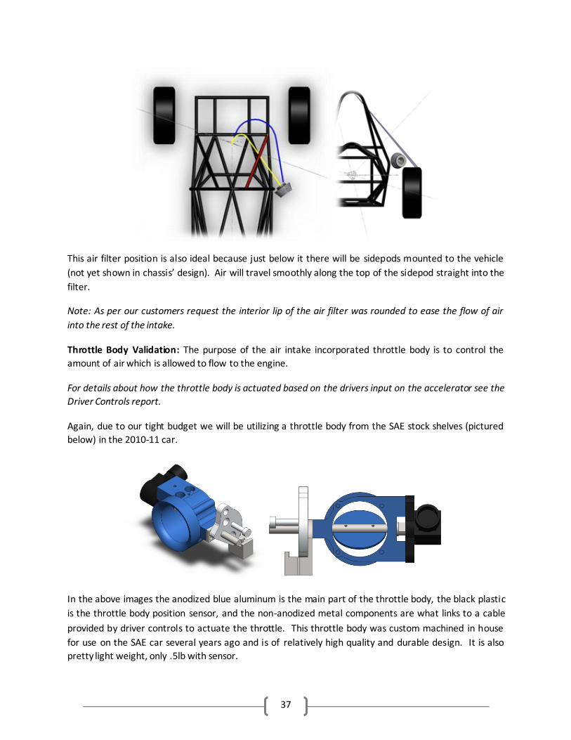
Throttle Body Validation: The purpose of the air intake incorporated throttle body is to control the
amount of air which is allowed to flow to the engine.
For details about how the throttle body is actuated based on the drivers input on the accelerator see the
Driver Controls report.
Again, due to our tight budget we will be utilizing a throttle body from the SAE stock shelves (pictured
below) in the 2010-11 car.
In the above images the anodized blue aluminum is the main part of the throttle body, the black plastic
is the throttle body position sensor, and the non-anodized metal components are what links to a cable
provided by driver controls to actuate the throttle. This throttle body was custom machined in house
for use on the SAE car several years ago and is of relatively high quality and durable design. It is also
pretty light weight, only .5lb with sensor.
38
Note: The two holes on the top of the blue body are for a vacuum sensor which can be installed and
hooked up to the ECU if desired in the future. For now these holes will be plugged with a custom part as
shown below…
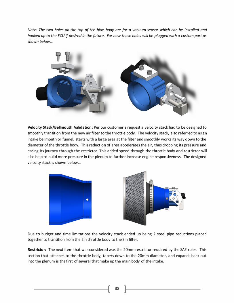
Velocity Stack/Bellmouth Validation: Per our customer’s request a velocity stack had to be designed to
smoothly transition from the new air filter to the throttle body. The velocity stack, also referred to as an
intake bellmouth or funnel, starts with a large area at the filter and smoothly works its way down to the
diameter of the throttle body. This reduction of area accelerates the air, thus dropping its pressure and
easing its journey through the restrictor. This added speed through the throttle body and restrictor will
also help to build more pressure in the plenum to further increase engine responsiveness. The designed
velocity stack is shown below…
Due to budget and time limitations the velocity stack ended up being 2 steel pipe reductions placed
together to transition from the 2in throttle body to the 3in filter.
Restrictor: The next item that was considered was the 20mm restrictor required by the SAE rules. This
section that attaches to the throttle body, tapers down to the 20mm diameter, and expands back out
into the plenum is the first of several that make up the main body of the intake.
39
Intake Support: There will be a short structural member attached to the frame via bolt and that
supports the restrictor as it is the thinnest area of the intake can be secured with a simple hose clamp.
This support will greatly reduce if not eliminate structural stress of the intake which is not designed to
be a force carrying component.
Prototype Concept Validation: Once past the restrictor there are only 2 main components of the intake
left; the air plenum and runner. These also happen to be the biggest components and have by far have
the biggest effect on engine performance. Some relatively common practices in performance air
systems are the use of baffles to change the effective length of the runner and moving internals to
change the effective volume of the plenum at different rpms. Such devices and design features are
considered outside the scope of our project this year but may very well be perused in future years. The
interior of all components will be as smooth as possible to reduce frictional surface drag and ease air
flow.
For this year, the goal is to design an intake with a plenum volume and runner length that
provide good engine power and responsiveness over the whole range of rpms. We will not be seeking
peaks where power is amazing in a small rpm range and terrible everywhere else. It has been
determined that the 09-10 car can put out ~39hp and ~52.88 ft-lbs of torque. Using one of the excel
spreadsheets from Dr. Timmins Powertrain Theory class it was determined that the 10% increase in
volumetric efficiency, that should correspond to a perfectly optimized intake, would yield gains of 3.9hp
and 5.28ft-lbs.
Without any more specific data it is very hard to complete any resonant frequency or acoustic
wave calculations which would normally be done for intake design. This lead to the decision that the
best way to get the proper diameters and lengths (volumes) of the plenum and runner would be
experimentally. Both of these components have been designed to be expandable over a certain range
so the car can be set up on a dyno and ever combination can be tried. For each arrangement the engine
will be given a basic tune and data will be pulled at 30, 50, 70, and 100% open throttle as to not miss any
disturbing peaks in performance. 3D plots can then be generated with runner length vs. plenum length
vs. horsepower or torque. Once the basic sizes are determined both SolidWorksFlowWorks 2010 and
Fluent will be used to perfect the final intake design before it is presented as a deliverable to the SAE
club for manufacturing. With actual data collected proper calculations will also be able to be done to
confirm theoretical performance.
Expandable Plenum Validation: The plenum on the final prototype is adjustable from 2.5*511cc to
5*511 cc via a set of PVC inserts. The 09-10 plenum was 2.5 times the displacement and all research
indicated that the plenum should be larger than that. Mr. Schwarz recommended the volume be ~3
times the displacement.
Straight Expandable Runner/Primary Length Validation: The runner, or primary length, is the tube that
connects the plenum to the engine. In general, a longer runner should be used to maximize low-speed
torque and a shorter one should be used to maximize (or at least prevent from decreasing) high speed
40
torque. The adjustability on the new prototype spans from 11.3 to 17.3in. The 09-10 runner was 13.3in
long.
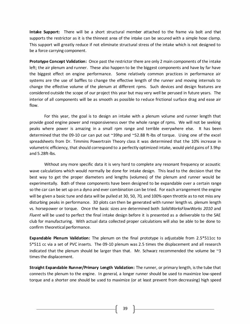
Runner/Primary Length Curve: When making this bend, there are
two critical considerations that seem to have been disregarded on
the 09-10 car. The first is that the bend should allow the intake to
get away from the hot engine as quickly as possible, instead of
wrapping around it. The second is that the bend should be as
gradual as possible as to not restrict flow. Internally, the different
sections of the intake need to be connected smoothly. The engines
fuel injector (shown right) sprays fuel into the runner tube. Located
just before the fuel injector,
a small hose must run from
the intake to the fuel
pressure regulator. This
provides the regulator with
the “ambient” pressure local to where the fuel is injected so it
can compare fuel pressure to that instead of the true ambient
pressure outside of the car. It is also the location of the fuel
pressure regulator local fuel injector ambient reference point
and the fuel injector itself.
Engine Mounting: Again, very similar to the 09-10 car
arrangement three bolts will be used to hold the intake firmly to the engine head. A rubber gasket will
also be utilized to prevent air and fuel leakage and hamper the transfer of heat and vibration from the
engine into the intake.
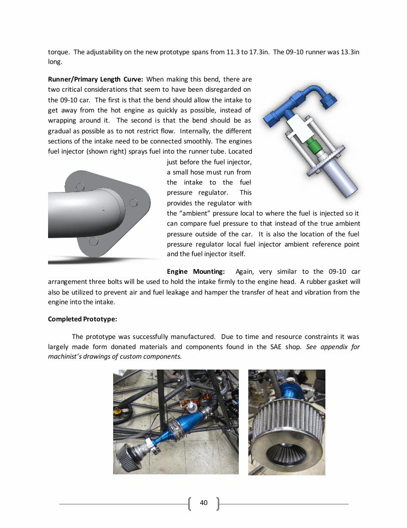
Completed Prototype:
The prototype was successfully manufactured. Due to time and resource constraints it was
largely made form donated materials and components found in the SAE shop. See appendix for
machinist’s drawings of custom components.
0
41
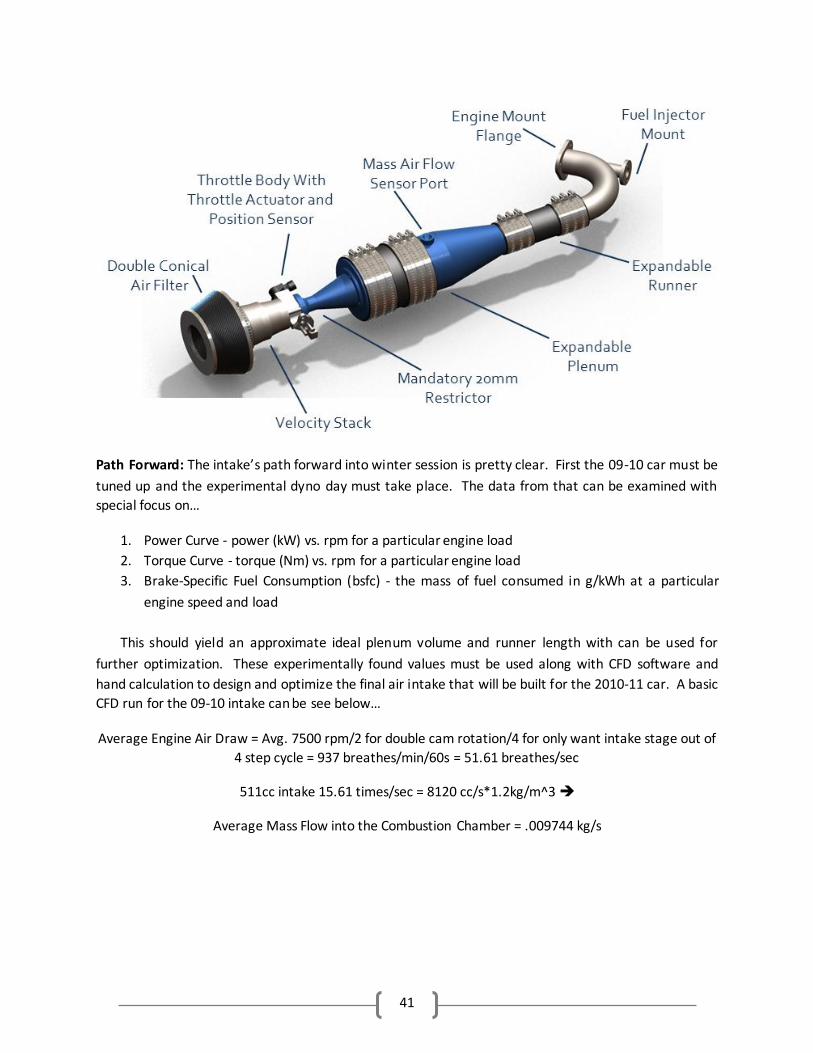
Path Forward: The intake’s path forward into winter session is pretty clear. First the 09-10 car must be
tuned up and the experimental dyno day must take place. The data from that can be examined with
special focus on…
1. Power Curve - power (kW) vs. rpm for a particular engine load
2. Torque Curve - torque (Nm) vs. rpm for a particular engine load
3. Brake-Specific Fuel Consumption (bsfc) - the mass of fuel consumed in g/kWh at a particular
engine speed and load
This should yield an approximate ideal plenum volume and runner length with can be used for
further optimization. These experimentally found values must be used along with CFD software and
hand calculation to design and optimize the final air intake that will be built for the 2010-11 car. A basic
CFD run for the 09-10 intake can be see below…
Average Engine Air Draw = Avg. 7500 rpm/2 for double cam rotation/4 for only want intake stage out of
4 step cycle = 937 breathes/min/60s = 51.61 breathes/sec
511cc intake 15.61 times/sec = 8120 cc/s*1.2kg/m^3
Average Mass Flow into the Combustion Chamber = .009744 kg/s
42
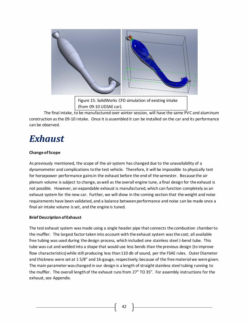
The final intake, to be manufactured over winter session, will have the same PVC and aluminum
construction as the 09-10 intake. Once it is assembled it can be installed on the car and its performance
can be observed.
Exhaust Change of Scope
As previously mentioned, the scope of the air system has changed due to the unavailability of a
dynamometer and complications to the test vehicle. Therefore, it will be impossible to physically test
for horsepower performance gains in the exhaust before the end of the semester. Because the air
plenum volume is subject to change, as well as the overall engine tune, a final design for the exhaust is
not possible. However, an expandable exhaust is manufactured, which can function completely as an
exhaust system for the new car. Further, we will show in the coming section that the weight and noise
requirements have been validated, and a balance between performance and noise can be made once a
final air intake volume is set, and the engine is tuned.
Brief Description of Exhaust
The test exhaust system was made using a single header pipe that connects the combustion chamber to
the muffler. The largest factor taken into account with the exhaust system was the cost; all available
free tubing was used during the design process, which included one stainless steel J-bend tube. This
tube was cut and welded into a shape that would use less bends than the previous design (to improve
flow characteristics) while still producing less than 110 db of sound, per the FSAE rules. Outer Diameter
and thickness were set at 1 5/8” and 16-gauge, respectively; because of the free material we were given.
The main parameter was changed in our design is a length of straight stainless steel tubing running to
the muffler. The overall length of the exhaust runs from 27” TO 35”. For assembly instructions for the
exhaust, see Appendix.
Figure 15: SolidWorks CFD simulation of existing intake
(from 09-10 UDSAE car).
43
The test exhaust is made up of two pieces and is tightly connected by a stainless steel band clamp. Of
these two pieces and the band clamp, there are has eight major components;
Piece One
1. Collar – Machined with mild steel to interface with the combustion chamber and the header. It is press fit and TIG welded into the beginning of the exhaust header.
2. Flange – A simple steel flange to hold the exhaust system securely to the engine. This was taken from the old exhaust system.
3. Header – This 1-5/8” OD tube runs from the collar to the transition. The length of the header will determine the power and noise characteristics of the exhaust system.
Piece Two
4. Transition –A simple 1/16” wall thickness, 2” to 1-3/4” Transition. The 1-3/4 side of the transition slides over the 1-5/8” header, to raise or lower the total length of the exhaust system. The 2” side is welded to a 3-1/2” length, 2” OD, stainless steel tube, which is welded to the muffler (this 2” tube was out into the system to match the previous exhaust design). The transition is made of mild steel and was one of our two purchases made in this system, which cost $4.50.
5. O2 Sensor Mount – This is an 18 mm pipe fitting which houses the O2 sensor. It is located on the wall of the 2” tube, 15 degrees offset from the centerline. The O2 sensor mount was created by purchasing a spark plug housing (whose threads fit the O2 sensor), and modifying in order to create accurate measurements of the Air: Fuel Ratio. (Not on car)
6. Muffler – The muffler was taken off the previous car. It is a FMF Q4 muffler, which was highly recommended from members of the FSAE club to be placed on the new car. The muffler is welded to the 2” tube and includes a flange that is connected to the chassis. It is the largest, most noise cancelling muffler that is freely available for Team Powertrain to use.
7. Muffler Mounting System – This mounting system takes advantage of the previous muffler mount and ads a piece to smoothly facilitate lengthening of the exhaust system.
Metrics
The primary focus of the metrics of the exhaust prototype has shifted away from performance, and
towards exhaust noise. Because our dyno day at Injection connection was cancelled, there is no way to
validate performance gains in horsepower and torque until after the semester is over.
A single noise trial was made at a short setting of the exhaust system, where the exhaust was set to a
main tube length of 30”. At 10,500 RPM, the engine made 120 dB, fast weighting. While the reading
would indicate that we have failed the noise test, many outside factors may have negatively influenced
its outcome;
44
a. The test was conducted in the outside parking lot with large buildings around it, so sound may have bounced back and influenced the readings. Traveling to a proper location to test for noise with the car could not be achieved in the past few days, once the exhaust was completed.
b. The muffler has not yet been repacked, which would definitely lower the sound reading. New muffler gauze is available to us in from the FSAE club and once it is repacked, noise level will go down.
c. The final air intake and final engine tune have not yet been finalized. Therefore, any noise targets that are made at this point will not stay the same after those systems are finalized.
More importantly, the reading was taken can show that the exhaust system was fully functional and in
the general range of decibel values that would pass the noise test. Further testing in the winter term
will conclude the validation of this noise metric.
Validation
Envelope
The FSAE rules govern the furthest positions outside the car that the exhaust can protrude. The exhaust
cannot be more than 17.7 inches behind the centerline of the rear axle, and cannot be be higher than
23.6 inches above the ground.
At the furthest extension, the axles are at a height of 21.5” above the ground, and they are 16” behind
the centerline of the axle. So, the exhaust system satisfies the requirements for enveloping for
competition.
Noise
The exhaust prototype can be used to test for noise and find a theoretical relationship between primary
exhaust tube length and engine noise. To ensure the exhaust prototype will pass the noise test, the new
exhaust prototype was modeled after the previous exhaust system, which passed the noise test. Many
attributes were carried over to the prototype design to mimic the previous system, which was
successful. Although constrained by costs, all of the materials that were used in the manufacture of the
new exhaust prototype were free of charge, and provided to our group by the FSAE club at Delaware.
The muffler, initial length of the primary tube, and copper insulating wrap were all taken from the old
design and implemented in the new exhaust prototype. Accounting for any new flow gains from the
intake and new engine tune, the exhaust prototype can extend up to seven inches longer than the
previous system, to ensure that the noise requirement will be met.
Path Forward
In order to perform the proper noise test, the muffler gauze first needs to repacked, which will lower
sound readings. Then an O2 sensor bung needs to be welded into the end of the main tube, in order to
properly measure the air:fuel ratio during dyno testing. Finally, a stainless steel band clamp needs to be
purchased to create an airtight seal between the two sliding exhaust pieces.
45
After these items are completed, there will be preliminary dyno testing done in the first week of winter
session, where an air intake volume and engine tune will be finalized. For this initial dyno testing, the
furthest length of exhaust will be used, and baseline performance data will be collected for this length of
exhaust main tube.
After the dyno day, the car will be taken to an open area, and iterations of noise tests will be done,
decreasing the length of the main tube after each trial, until the noise readings hit 110 dB. Once this
location is set, a second dyno day will prove any performance increases associated with the change in
the main tube.
The new exhaust prototype uses stainless steel tubes and one temporary mild steel transition. The
stainless steel will hold not rust and be reliable for the competition, and once a final primary length is
set, the galvanized steel transition will be replaced with a stainless steel one.
Project Aspect 3: Cooling Description
The cooling system of the car is responsible for
preventing engine seize and overheating. The system
involves a radiator, fan, and coolant. Our team has
successfully selected the components to be used in
the system and proved that their performance on the
car will surpass our metrics.
Constraints
The following constraints had to be taken into account when designing the cooling system for
the 2011 FSAE car:
1. Must only use water through radiator as coolant 2. Hot coolant must be shielded or insulated from direct contact with the driver
3. Radiator pull fan must not drain battery when running with all other vehicle electronics 4. Radiator must be oriented perpendicular to the air flow 5. System must have sealed ducting
6. Assembly must fit within chassis design
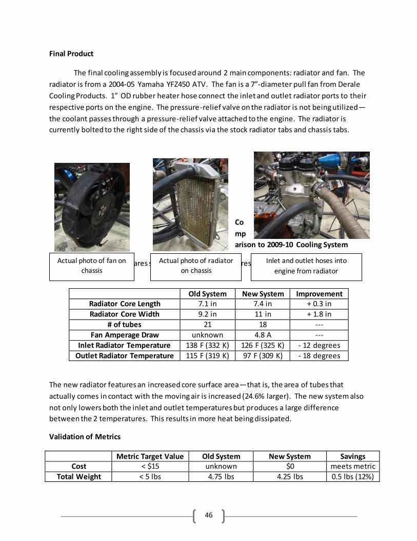
46
Final Product
The final cooling assembly is focused around 2 main components: radiator and fan. The
radiator is from a 2004-05 Yamaha YFZ450 ATV. The fan is a 7”-diameter pull fan from Derale
Cooling Products. 1” OD rubber heater hose connect the inlet and outlet radiator ports to their
respective ports on the engine. The pressure-relief valve on the radiator is not being utilized—
the coolant passes through a pressure-relief valve attached to the engine. The radiator is
currently bolted to the right side of the chassis via the stock radiator tabs and chassis tabs.
Co
mp
arison to 2009-10 Cooling System
The following table compares some dimensions and features of the new cooling system to
those of the new system:
Old System New System Improvement Radiator Core Length 7.1 in 7.4 in + 0.3 in
Radiator Core Width 9.2 in 11 in + 1.8 in
# of tubes 21 18 ---
Fan Amperage Draw unknown 4.8 A ---
Inlet Radiator Temperature 138 F (332 K) 126 F (325 K) - 12 degrees
Outlet Radiator Temperature 115 F (319 K) 97 F (309 K) - 18 degrees
The new radiator features an increased core surface area—that is, the area of tubes that
actually comes in contact with the moving air is increased (24.6% larger). The new system also
not only lowers both the inlet and outlet temperatures but produces a large difference
between the 2 temperatures. This results in more heat being dissipated.
Validation of Metrics
Metric Target Value Old System New System Savings Cost < $15 unknown $0 meets metric
Total Weight < 5 lbs 4.75 lbs 4.25 lbs 0.5 lbs (12%)
Actual photo of fan on
chassis
Actual photo of radiator
on chassis
Inlet and outlet hoses into
engine from radiator
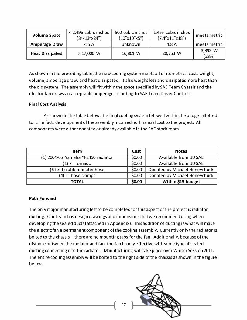
47
Volume Space < 2,496 cubic inches
(8”x13”x24”) 500 cubic inches
(10”x10”x5”) 1,465 cubic inches
(7.4”x11”x18”) meets metric
Amperage Draw < 5 A unknown 4.8 A meets metric
Heat Dissipated > 17,000 W 16,861 W 20,753 W 3,892 W
(23%)
As shown in the preceding table, the new cooling system meets all of its metrics: cost, weight,
volume, amperage draw, and heat dissipated. It also weighs less and dissipates more heat than
the old system. The assembly will fit within the space specified by SAE Team Chassis and the
electric fan draws an acceptable amperage according to SAE Team Driver Controls.
Final Cost Analysis
As shown in the table below, the final cooling system fell well within the budget allotted
to it. In fact, development of the assembly incurred no financial cost to the project. All
components were either donated or already available in the SAE stock room.
Item Cost Notes
(1) 2004-05 Yamaha YFZ450 radiator $0.00 Available from UD SAE
(1) 7” Tornado $0.00 Available from UD SAE
(6 feet) rubber heater hose $0.00 Donated by Michael Honeychuck (4) 1” hose clamps $0.00 Donated by Michael Honeychuck
TOTAL $0.00 Within $15 budget
Path Forward
The only major manufacturing left to be completed for this aspect of the project is radiator
ducting. Our team has design drawings and dimensions that we recommend using when
developing the sealed ducts (attached in Appendix). This addition of ducting is what will make
the electric fan a permanent component of the cooling assembly. Currently only the radiator is
bolted to the chassis—there are no mounting tabs for the fan. Additionally, because of the
distance between the radiator and fan, the fan is only effective with some type of sealed
ducting connecting it to the radiator. Manufacturing will take place over Winter Session 2011.
The entire cooling assembly will be bolted to the right side of the chassis as shown in the figure
below.
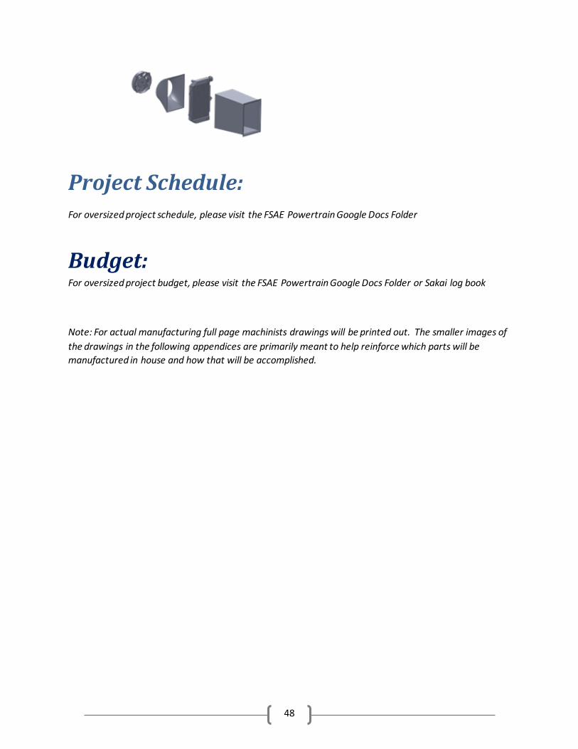
48
Project Schedule:
For oversized project schedule, please visit the FSAE Powertrain Google Docs Folder
Budget: For oversized project budget, please visit the FSAE Powertrain Google Docs Folder or Sakai log book
Note: For actual manufacturing full page machinists drawings will be printed out. The smaller images of
the drawings in the following appendices are primarily meant to help reinforce which parts will be
manufactured in house and how that will be accomplished.
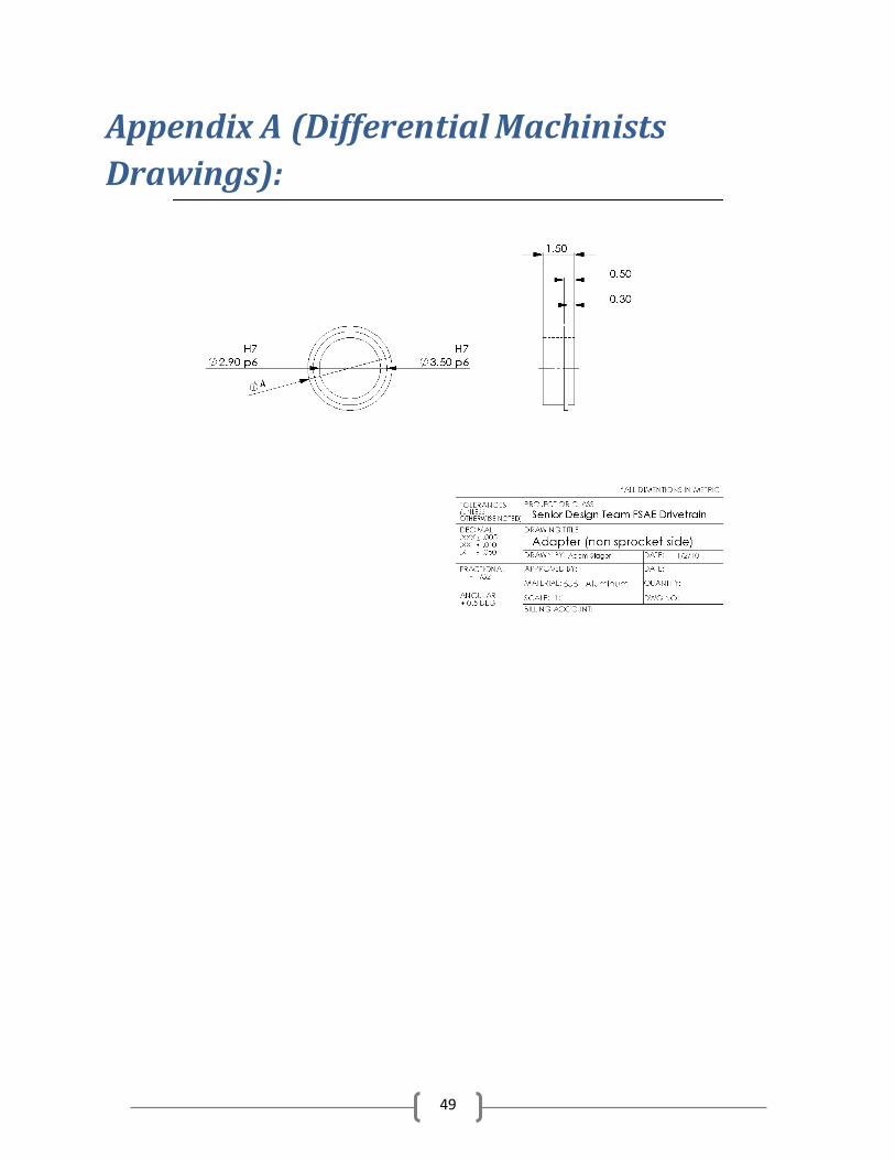
49
Appendix A (Differential Machinists
Drawings):
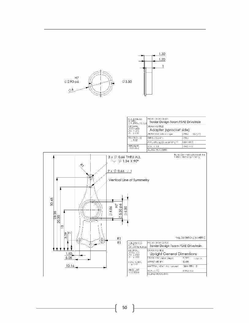
50
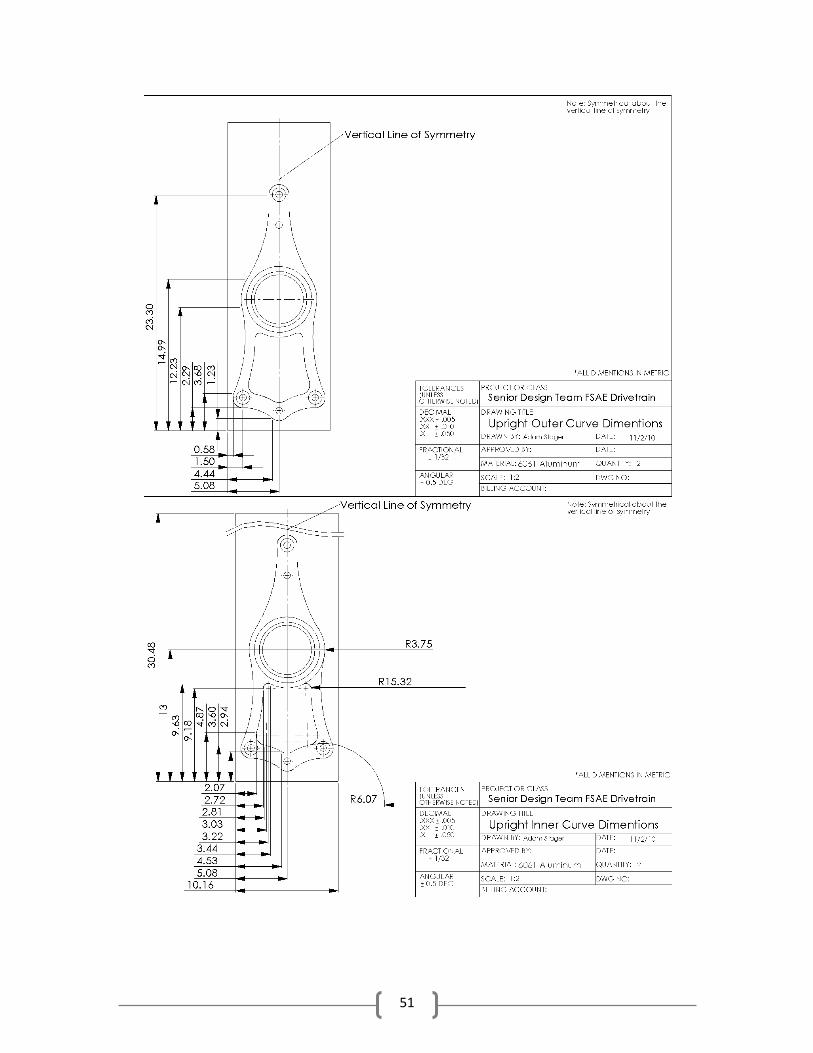
51
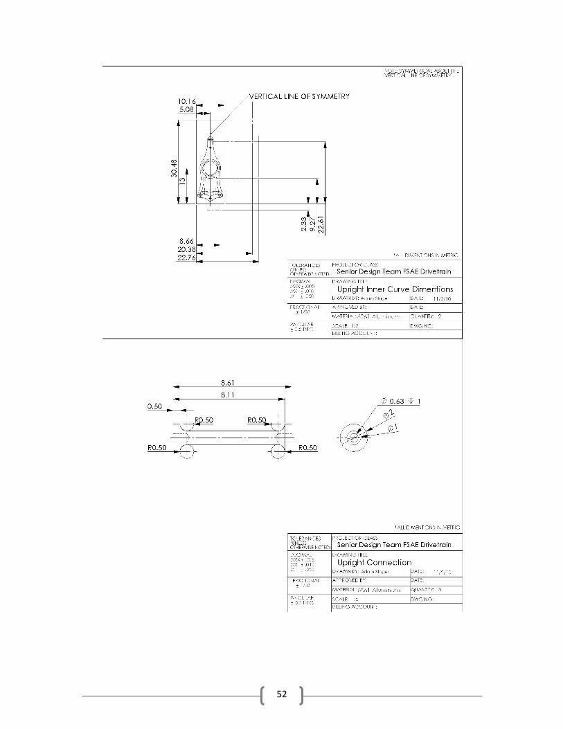
52
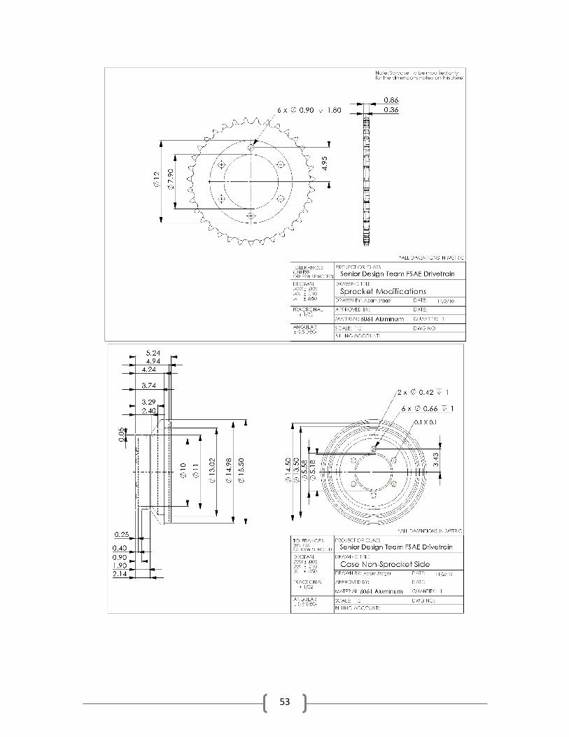
53
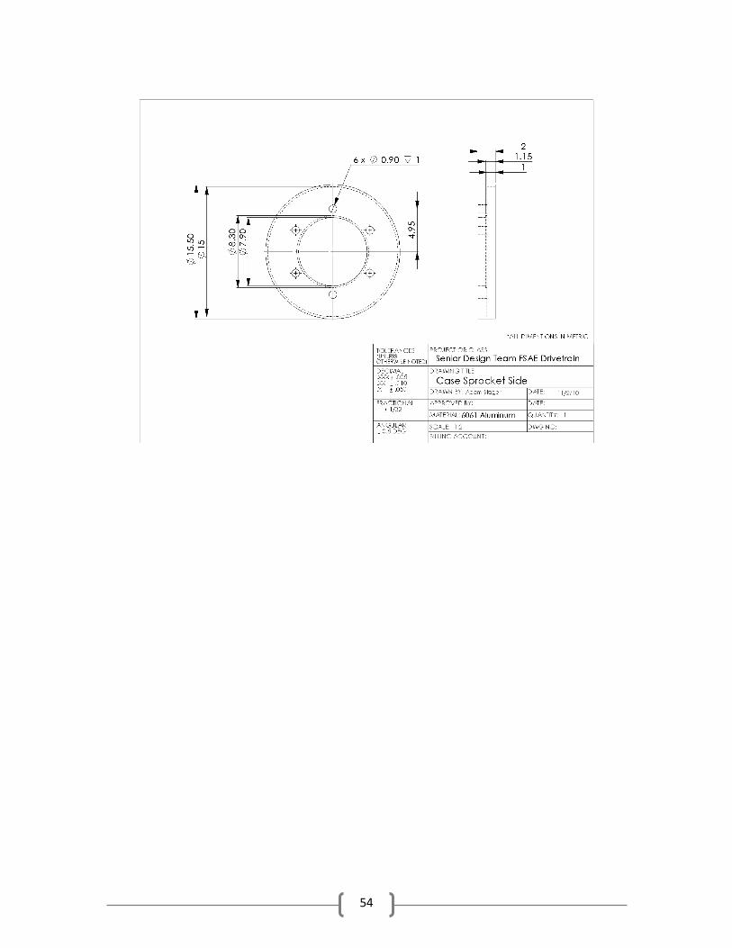
54
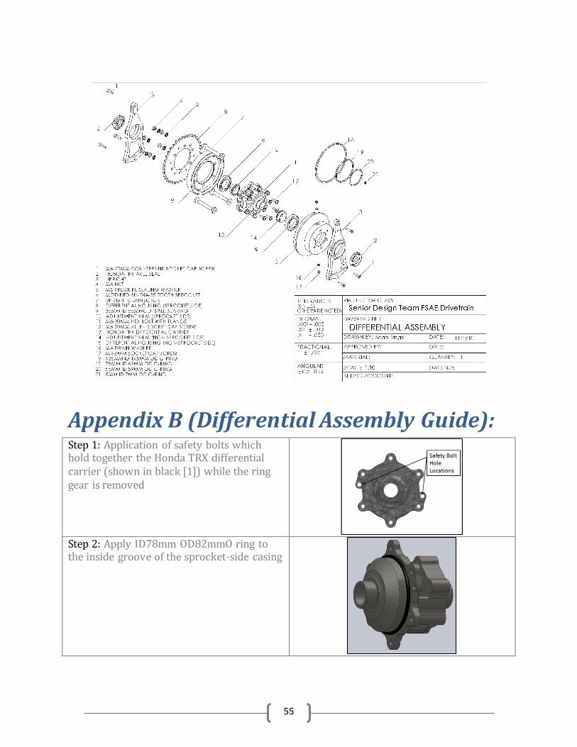
55
Appendix B (Differential Assembly Guide): Step 1: Application of safety bolts which hold together the Honda TRX differential carrier (shown in black [1]) while the ring gear is removed
Step 2: Apply ID78mm OD82mmO ring to the inside groove of the sprocket-side casing
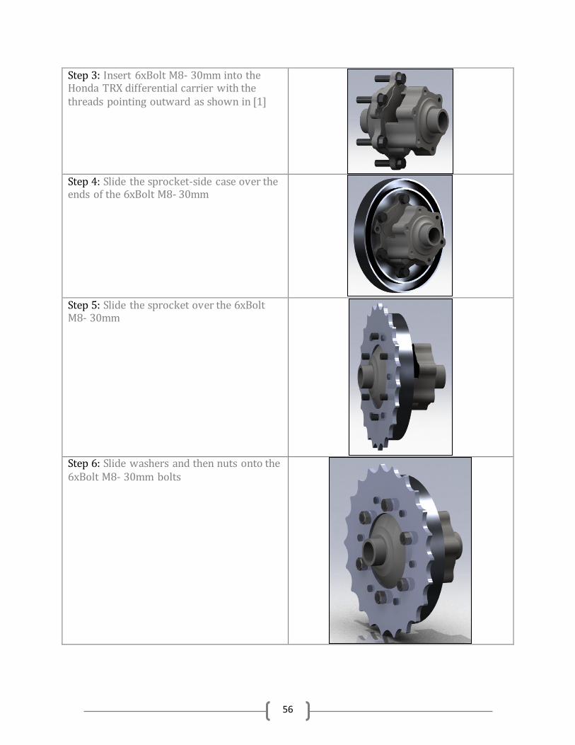
56
Step 3: Insert 6xBolt M8- 30mm into the Honda TRX differential carrier with the threads pointing outward as shown in [1]
Step 4: Slide the sprocket-side case over the ends of the 6xBolt M8- 30mm
Step 5: Slide the sprocket over the 6xBolt M8- 30mm
Step 6: Slide washers and then nuts onto the 6xBolt M8- 30mm bolts
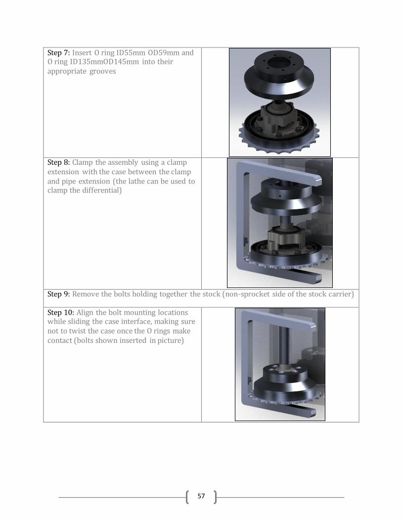
57
Step 7: Insert O ring ID55mm OD59mm and O ring ID135mmOD145mm into their appropriate grooves
Step 8: Clamp the assembly using a clamp extension with the case between the clamp and pipe extension (the lathe can be used to clamp the differential)
Step 9: Remove the bolts holding together the stock (non-sprocket side of the stock carrier)
Step 10: Align the bolt mounting locations while sliding the case interface, making sure not to twist the case once the O rings make contact (bolts shown inserted in picture)
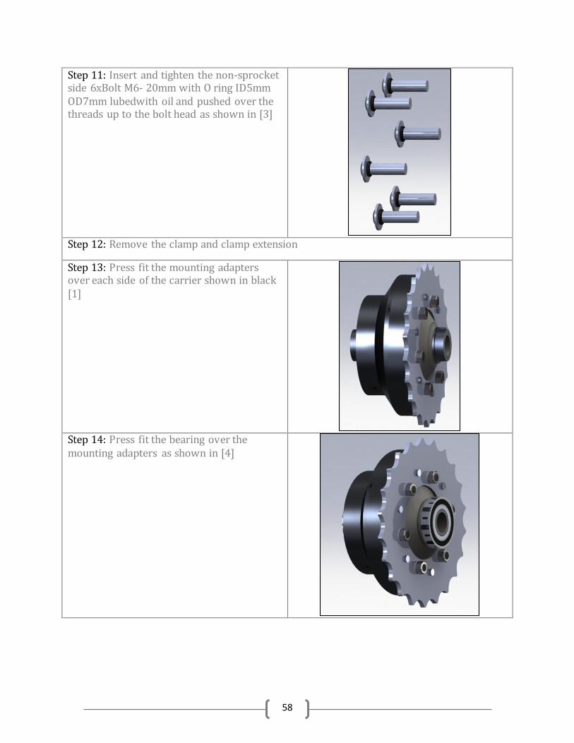
58
Step 11: Insert and tighten the non-sprocket side 6xBolt M6- 20mm with O ring ID5mm OD7mm lubedwith oil and pushed over the threads up to the bolt head as shown in [3]
Step 12: Remove the clamp and clamp extension
Step 13: Press fit the mounting adapters over each side of the carrier shown in black [1]
Step 14: Press fit the bearing over the mounting adapters as shown in [4]
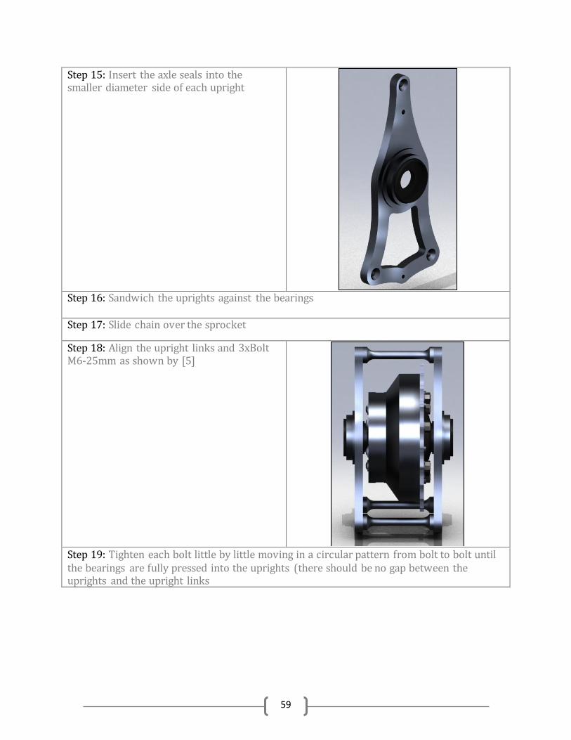
59
Step 15: Insert the axle seals into the smaller diameter side of each upright
Step 16: Sandwich the uprights against the bearings Step 17: Slide chain over the sprocket
Step 18: Align the upright links and 3xBolt M6-25mm as shown by [5]
Step 19: Tighten each bolt little by little moving in a circular pattern from bolt to bolt until the bearings are fully pressed into the uprights (there should be no gap between the uprights and the upright links
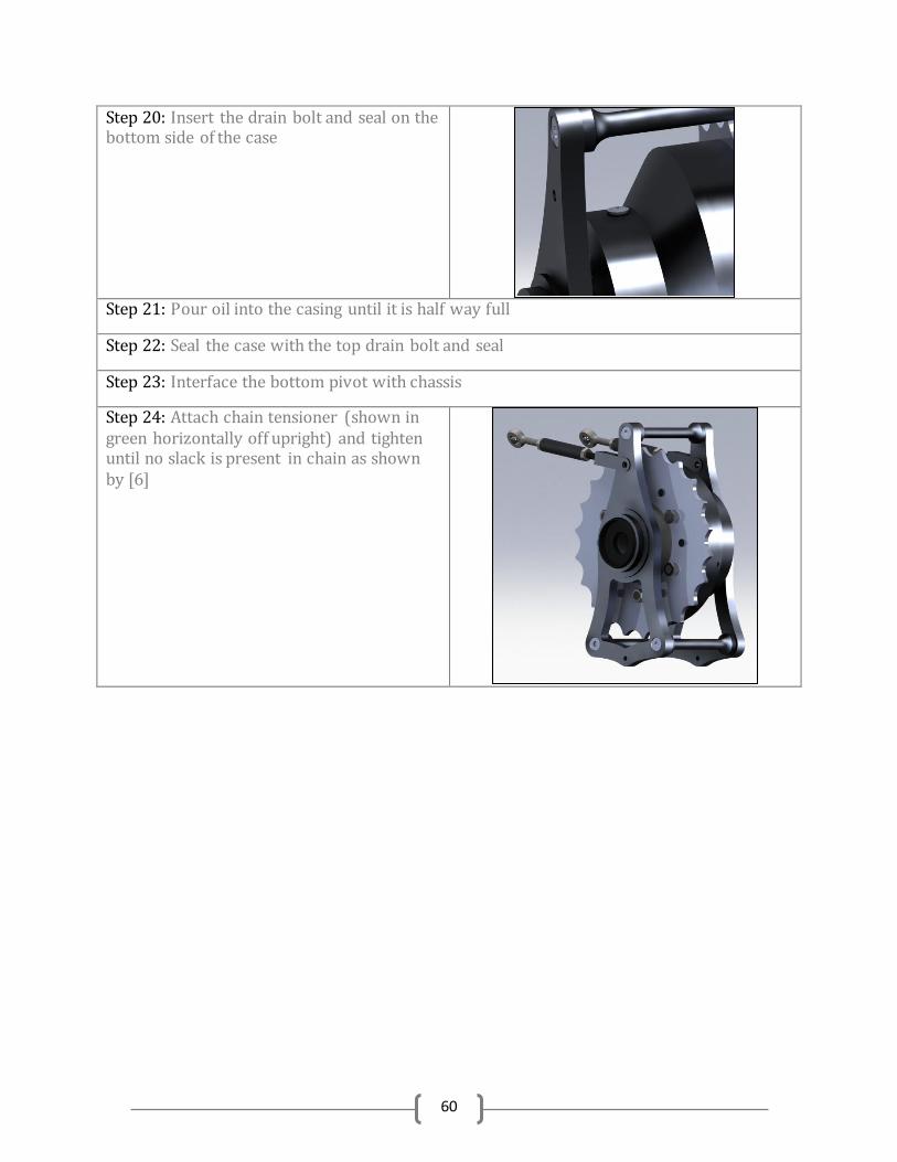
60
Step 20: Insert the drain bolt and seal on the bottom side of the case
Step 21: Pour oil into the casing until it is half way full
Step 22: Seal the case with the top drain bolt and seal
Step 23: Interface the bottom pivot with chassis
Step 24: Attach chain tensioner (shown in green horizontally off upright) and tighten until no slack is present in chain as shown by [6]
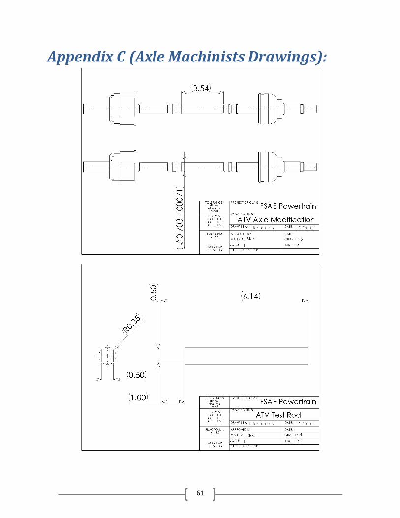
61
Appendix C (Axle Machinists Drawings):
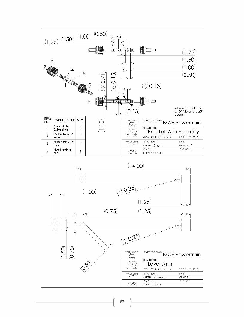
62
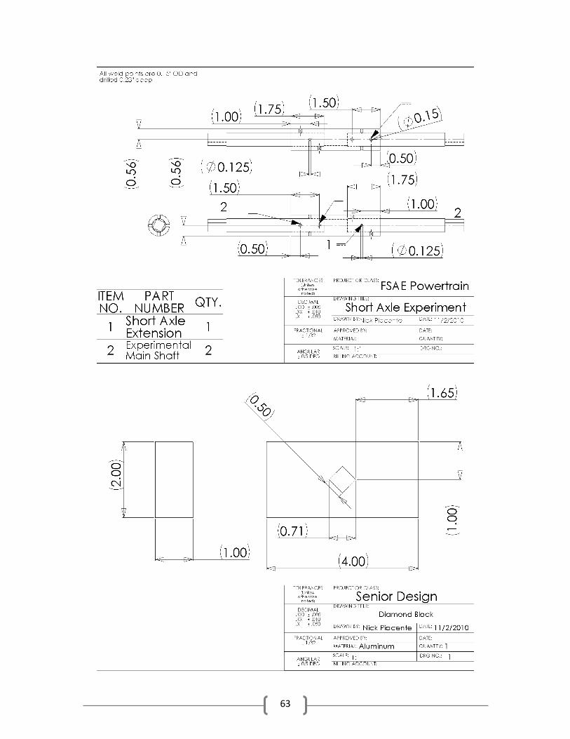
63
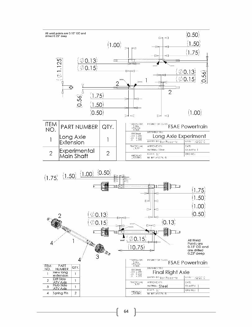
64
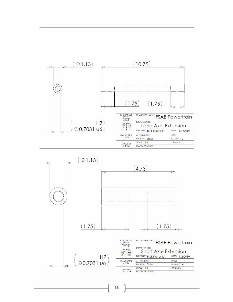
65
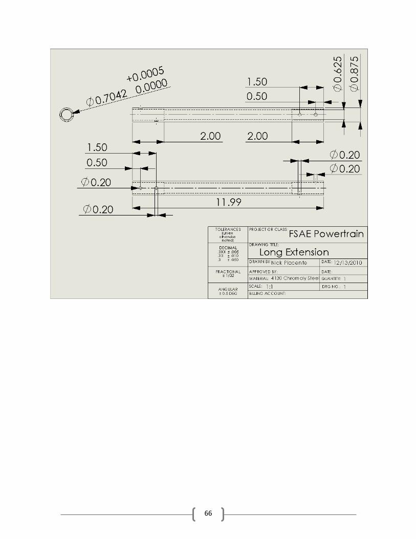
66
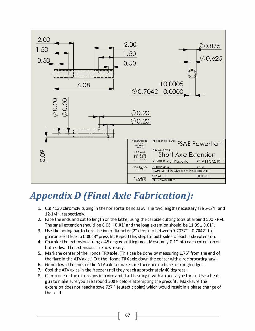
67
Appendix D (Final Axle Fabrication):
1. Cut 4130 chromoly tubing in the horizontal band saw. The two lengths necessary are 6-1/4” and 12-1/4”, respectively.
2. Face the ends and cut to length on the lathe, using the carbide cutting tools at around 500 RPM. The small extention should be 6.08 and the long extention should be 11.99 ± 0.01”.
3. Use the boring bar to bore the inner diameter (2” deep) to between 0.7037” – 0.7042” to guarantee at least a 0.0013” press fit. Repeat this step for both sides of each axle extension.
4. Chamfer the extensions using a 45 degree cutting tool. Move only 0.1” into each extension on both sides. The extensions are now ready.
5. Mark the center of the Honda TRX axle. (This can be done by measuring 1.75” from the end of the flare in the ATV axle.) Cut the Honda TRX axle down the center with a reciprocating saw.
6. Grind down the ends of the ATV axle to make sure there are no burrs or rough edges. 7. Cool the ATV axles in the freezer until they reach approximately 40 degrees. 8. Clamp one of the extensions in a vice and start heating it with an acetalyne torch. Use a heat
gun to make sure you are around 500 F before attempting the press fit. Make sure the extension does not reach above 727 F (eutectic point) which would result in a phase change of the solid.
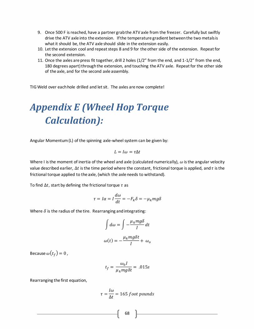
68
9. Once 500 F is reached, have a partner grab the ATV axle from the freezer. Carefully but swiftly drive the ATV axle into the extension. If the temperature gradient between the two metals is what it should be, the ATV axle should slide in the extension easily.
10. Let the extension cool and repeat steps 8 and 9 for the other side of the extension. Repeat for the second extension.
11. Once the axles are press fit together, drill 2 holes (1/2” from the end, and 1-1/2” from the end, 180 degrees apart) through the extension, and touching the ATV axle. Repeat for the other side of the axle, and for the second axle assembly.
TIG Weld over each hole drilled and let sit. The axles are now complete!
Appendix E (Wheel Hop Torque
Calculation):
Angular Momentum (L) of the spinning axle-wheel system can be given by:
Where I is the moment of inertia of the wheel and axle (calculated numerically), is the angular velocity
value described earlier, is the time period where the constant, frictional torque is applied, and is the
frictional torque applied to the axle, (which the axle needs to withstand).
To find , start by defining the frictional torque as
Where is the radius of the tire. Rearranging and integrating:
∫ ∫
( )
Because ( ) ,
Rearranging the first equation,
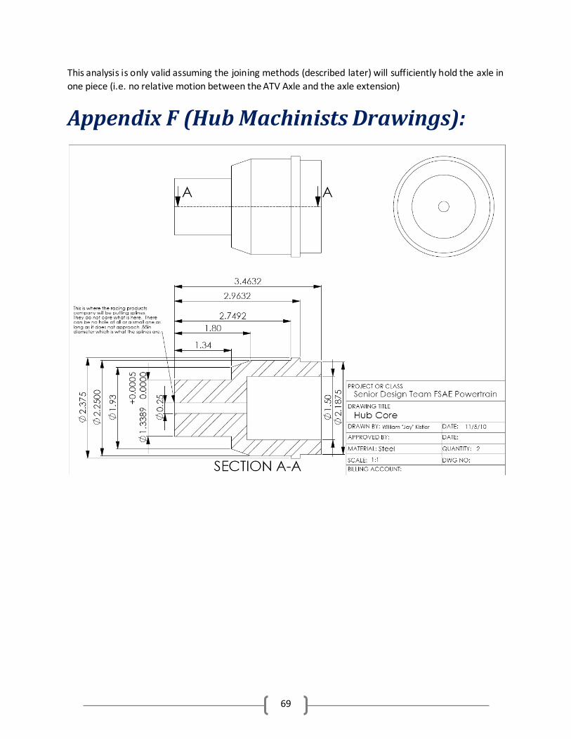
69
This analysis is only valid assuming the joining methods (described later) will sufficiently hold the axle in
one piece (i.e. no relative motion between the ATV Axle and the axle extension)
Appendix F (Hub Machinists Drawings):
70
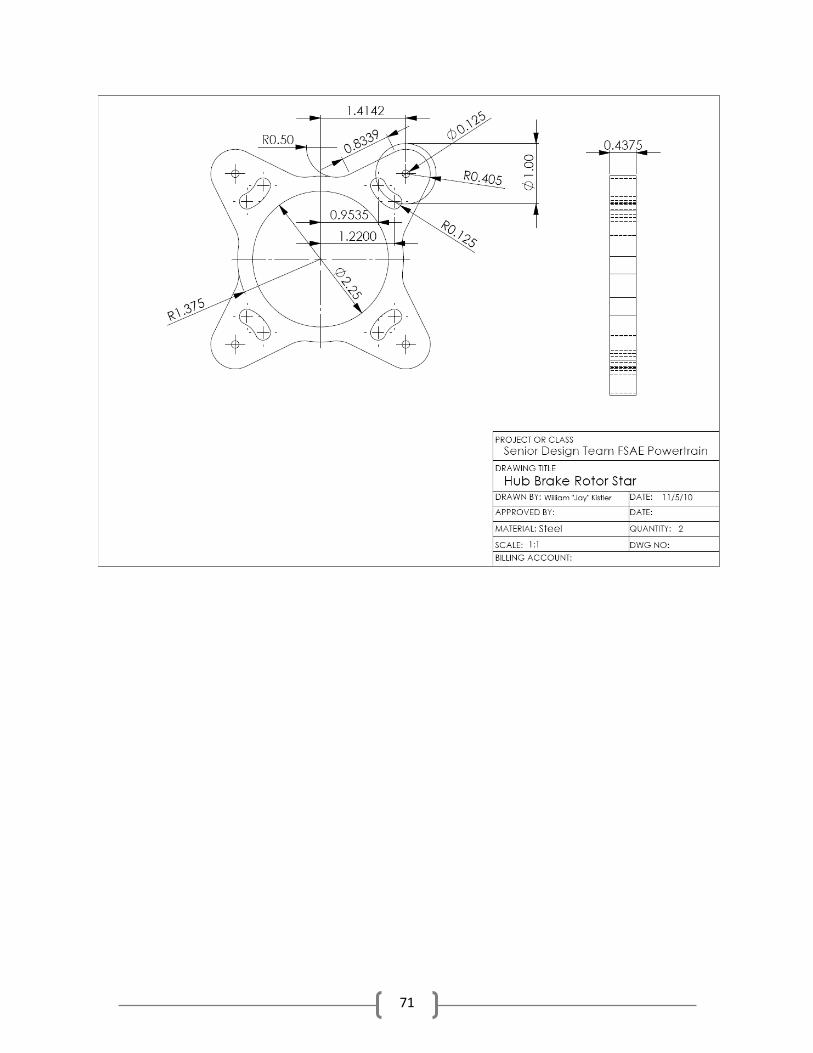
71
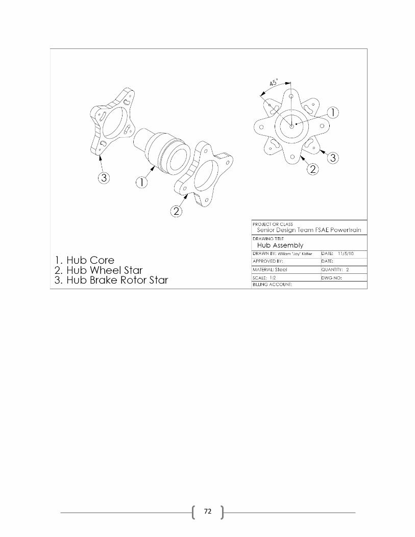
72
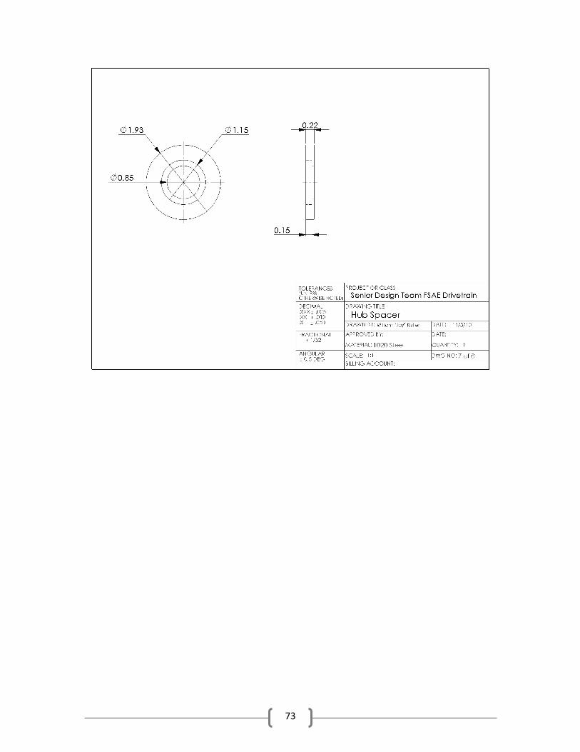
73
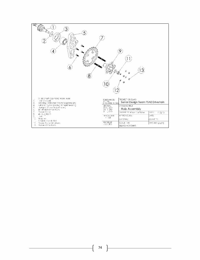
74
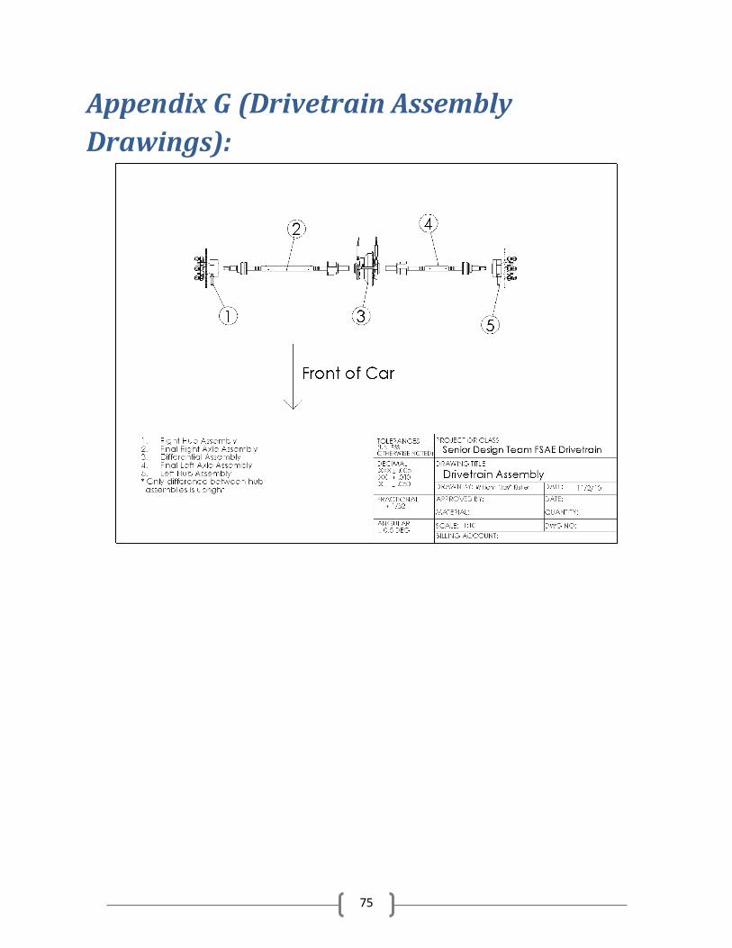
75
Appendix G (Drivetrain Assembly
Drawings):
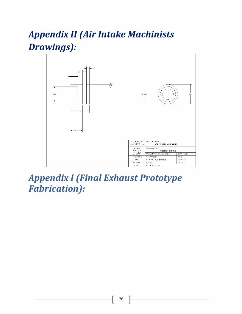
76
Appendix H (Air Intake Machinists
Drawings):
Appendix I (Final Exhaust Prototype Fabrication):
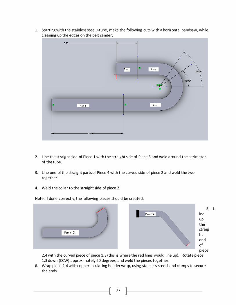
77
1. Starting with the stainless steel J-tube, make the following cuts with a horizontal bandsaw, while cleaning up the edges on the belt sander:
2. Line the straight side of Piece 1 with the straight side of Piece 3 and weld around the perimeter of the tube.
3. Line one of the straight parts of Piece 4 with the curved side of piece 2 and weld the two together.
4. Weld the collar to the straight side of piece 2.
Note: If done correctly, the following pieces should be created:
5. Line up the straight end of piece
2,4 with the curved piece of piece 1,3 (this is where the red lines would line up). Rotate piece 1,3 down (CCW) approximately 20 degrees, and weld the pieces together.
6. Wrap piece 2,4 with copper insulating header wrap, using stainless steel band clamps to secure the ends.
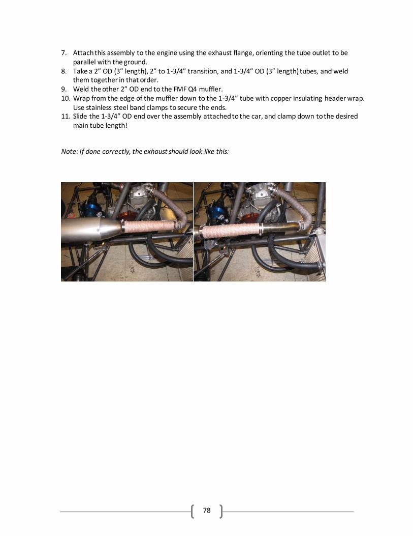
78
7. Attach this assembly to the engine using the exhaust flange, orienting the tube outlet to be parallel with the ground.
8. Take a 2” OD (3” length), 2” to 1-3/4” transition, and 1-3/4” OD (3” length) tubes, and weld them together in that order.
9. Weld the other 2” OD end to the FMF Q4 muffler. 10. Wrap from the edge of the muffler down to the 1-3/4” tube with copper insulating header wrap.
Use stainless steel band clamps to secure the ends. 11. Slide the 1-3/4” OD end over the assembly attached to the car, and clamp down to the desired
main tube length!
Note: If done correctly, the exhaust should look like this:
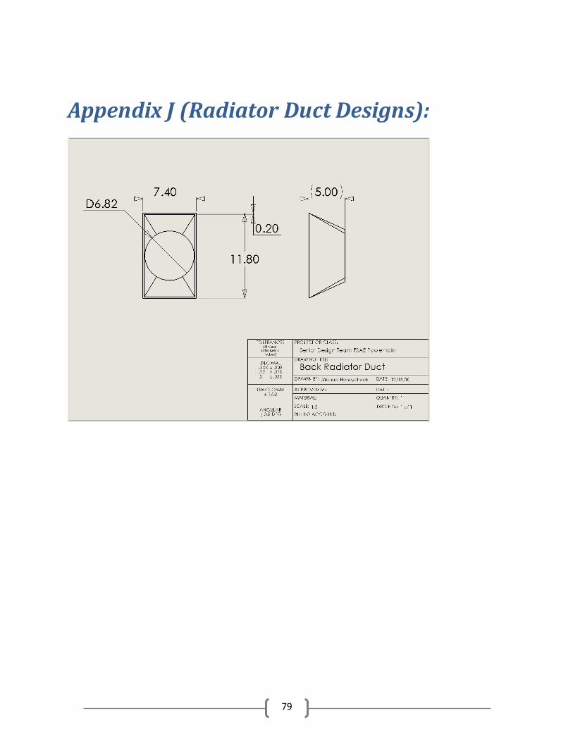
79
Appendix J (Radiator Duct Designs):
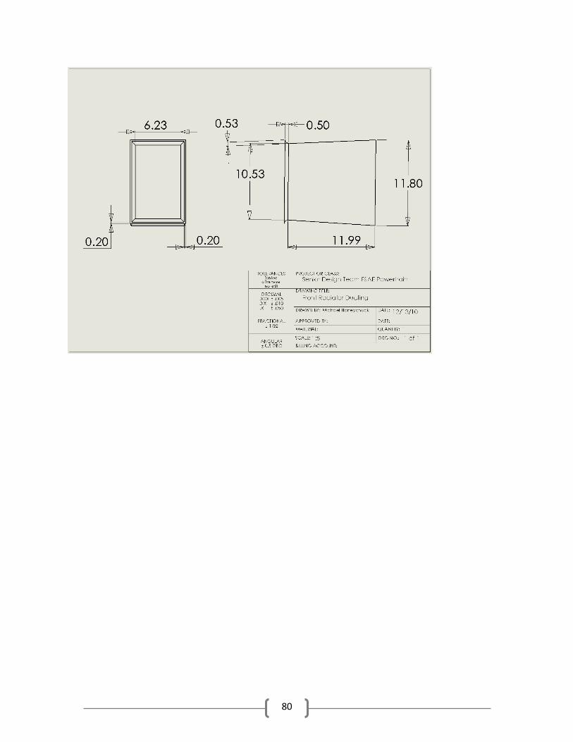
80