Embed Size (px)
Citation preview
`
E - m a i l : r a j s i n h p a r d e s h i @ g m a i l . c o m C e l l N o : 9 8 2 4 2 7 3 8 7 7
Formwork, Scaffolding,
Shoring & Underpinning Compiled & Prepared by R.P.Pardeshi
BUILDING CONSTRUCTION IV
E - m a i l : r a j s i n h p a r d e s h i @ g m a i l . c o m C e l l N o : 9 8 2 4 2 7 3 8 7 7
Page 1
Formwork, Scaffolding, Shoring & Underpinning
FORMWORK
INTRODUCTION
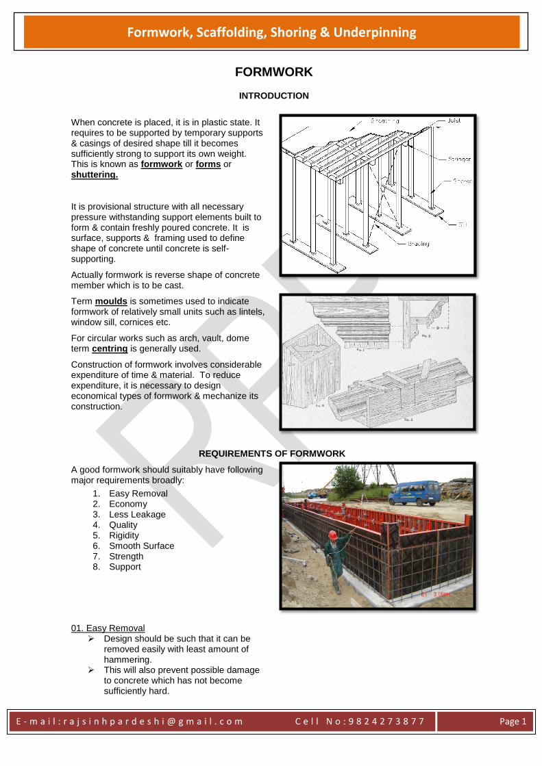
When concrete is placed, it is in plastic state. It requires to be supported by temporary supports & casings of desired shape till it becomes sufficiently strong to support its own weight. This is known as formwork or forms or shuttering.
It is provisional structure with all necessary pressure withstanding support elements built to form & contain freshly poured concrete. It is surface, supports & framing used to define shape of concrete until concrete is self-supporting.
Actually formwork is reverse shape of concrete member which is to be cast.
Term moulds is sometimes used to indicate formwork of relatively small units such as lintels, window sill, cornices etc.
For circular works such as arch, vault, dome term centring is generally used.
Construction of formwork involves considerable expenditure of time & material. To reduce expenditure, it is necessary to design economical types of formwork & mechanize its construction.
REQUIREMENTS OF FORMWORK
A good formwork should suitably have following major requirements broadly:
1. Easy Removal 2. Economy 3. Less Leakage 4. Quality 5. Rigidity 6. Smooth Surface 7. Strength 8. Support
01. Easy Removal Design should be such that it can be
removed easily with least amount of hammering.
This will also prevent possible damage to concrete which has not become sufficiently hard.
E - m a i l : r a j s i n h p a r d e s h i @ g m a i l . c o m C e l l N o : 9 8 2 4 2 7 3 8 7 7
Page 2
Formwork, Scaffolding, Shoring & Underpinning
Further, if removal is easy, it can be made fit for reuse with little expenditure.
When concrete has reached certain required strength, the form is no longer needed & is removed.
Operation of removing form work is commonly known as stripping.
When stripping takes place, components of form work are removed & then reused for forms of another part of structures.
Such forms, whose components can be reused several times, are known as panel forms.
02. Economy
It is to be noted that formwork does not contribute to stability of finished structure & hence it will be desirable to bring down cost to minimum consistent with safety.
Following steps can be adopted to effect economy of form work :
Reduction in number of irregular shapes Standardizing room dimensions Use of components parts of commercial
sizes Putting formwork in use again as early
as possible
Formwork should be constructed of that material which is easily available at low cost & which can be reused for several times.
03. Less Leakages
Formwork should be so arranged that there is minimum of leakage through joints. This is achieved by providing tight joint between adjacent sections of formwork
04. Quality
Forms should be designed & built accurately so that the desired size, shape & finish of concrete is attained.
05. Rigidity
Formwork should be rigid enough so as to retain shape without any appreciable deformation. For visible surfaces in completed work the deflection is limited to 1/300 of span & for hidden surface, to 1/15 span. It should also be noted that rigid form work will be robust & stiff enough to allow repeated use.
06. Smooth Surface
Inside surface of formwork should be smooth so as to turn out a good concrete surface. This is achieved by
applying crude oil or
soft soap solution to inside surface of
form work.
E - m a i l : r a j s i n h p a r d e s h i @ g m a i l . c o m C e l l N o : 9 8 2 4 2 7 3 8 7 7
Page 3
Formwork, Scaffolding, Shoring & Underpinning
This also makes removal of formwork easy.
07. Strength
Formwork should be sufficiently strong enough to bear dead load of wet concrete as well as weight of equipment, labour etc. required for placing & compacting concrete.
This required careful design of formwork. Over estimation of loads result into expensive formwork & under estimation of loads result into failure of form work.
Loads on vertical forms are to be assessed from various consideration such as :
Density of concrete Dimensions of sections Concrete temperature Slump of concrete Reinforcement details Stiffness of forms and Rate of pouring of concrete
08. Supports
Formwork should rest on: Sound Hard & Non-yielding support
COST OF FORMWORK
Cost of formwork plays significant role in cost of concrete. It varies from 30% to 40% of cost of concrete in ordinary structure & may go as high as 50% to 60% for special structures such as dam, bridges etc.
Four major components contributing to cost of formwork are:
1. Cost of formwork material 2. Cost of erection, placing & removal of
formwork 3. Cost of joining materials such as nails,
wires etc. 4. Cost of labour for fabrication of
formwork
In general, it can be stated that careful watch should be kept on cost of formwork & all attempts should be made to bring down cost of formwork to minimum so as to achieve overall economy in concrete work.
IS ON FORMWORK
E - m a i l : r a j s i n h p a r d e s h i @ g m a i l . c o m C e l l N o : 9 8 2 4 2 7 3 8 7 7
Page 4
Formwork, Scaffolding, Shoring & Underpinning
01. General
Formwork shall conform to shape, lines & dimensions as shown on plans & be so constructed as to remain sufficiently rigid during placing & compacting of concrete & shall be sufficiently tight to prevent loss of liquid from concrete
02. Cleaning & Treatment of Forms
All rubbish, particularly chippings, shavings & sawdust shall be removed from interior of forms before concrete is placed & formwork shall be cleaned thoroughly wetted or treated with an approved composition
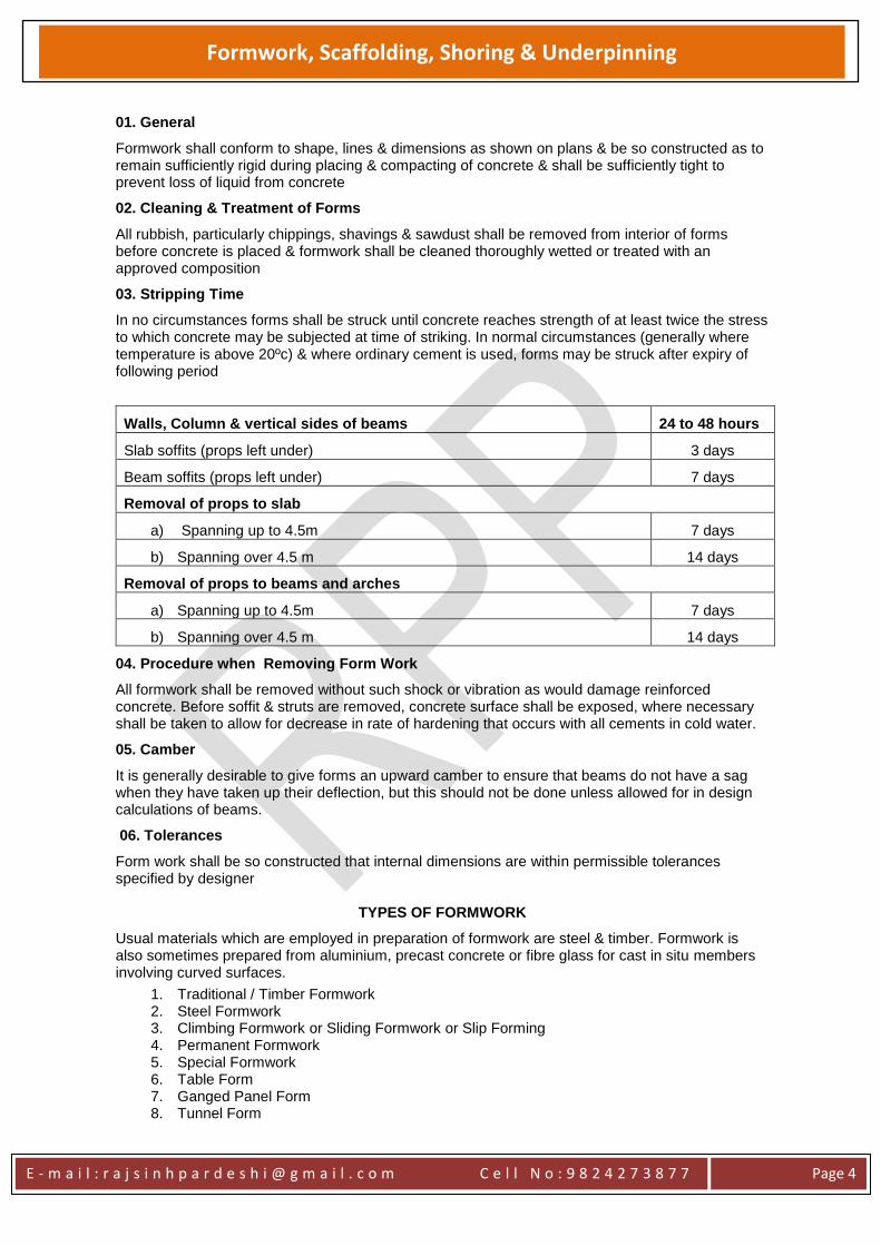
03. Stripping Time
In no circumstances forms shall be struck until concrete reaches strength of at least twice the stress to which concrete may be subjected at time of striking. In normal circumstances (generally where temperature is above 20ºc) & where ordinary cement is used, forms may be struck after expiry of following period
Walls, Column & vertical sides of beams 24 to 48 hours
Slab soffits (props left under) 3 days
Beam soffits (props left under) 7 days
Removal of props to slab
a) Spanning up to 4.5m 7 days
b) Spanning over 4.5 m 14 days
Removal of props to beams and arches
a) Spanning up to 4.5m 7 days
b) Spanning over 4.5 m 14 days
04. Procedure when Removing Form Work
All formwork shall be removed without such shock or vibration as would damage reinforced concrete. Before soffit & struts are removed, concrete surface shall be exposed, where necessary shall be taken to allow for decrease in rate of hardening that occurs with all cements in cold water.
05. Camber
It is generally desirable to give forms an upward camber to ensure that beams do not have a sag when they have taken up their deflection, but this should not be done unless allowed for in design calculations of beams.
06. Tolerances
Form work shall be so constructed that internal dimensions are within permissible tolerances specified by designer
TYPES OF FORMWORK
Usual materials which are employed in preparation of formwork are steel & timber. Formwork is also sometimes prepared from aluminium, precast concrete or fibre glass for cast in situ members involving curved surfaces.
1. Traditional / Timber Formwork 2. Steel Formwork 3. Climbing Formwork or Sliding Formwork or Slip Forming 4. Permanent Formwork 5. Special Formwork 6. Table Form 7. Ganged Panel Form 8. Tunnel Form
E - m a i l : r a j s i n h p a r d e s h i @ g m a i l . c o m C e l l N o : 9 8 2 4 2 7 3 8 7 7
Page 5
Formwork, Scaffolding, Shoring & Underpinning
9. Doka Formwork System
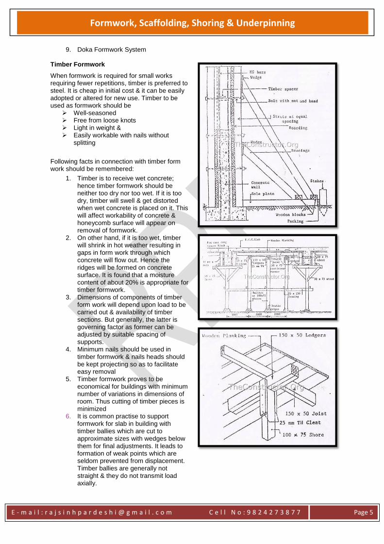
Timber Formwork
When formwork is required for small works requiring fewer repetitions, timber is preferred to steel. It is cheap in initial cost & it can be easily adopted or altered for new use. Timber to be used as formwork should be
Well-seasoned Free from loose knots Light in weight & Easily workable with nails without
splitting
Following facts in connection with timber form work should be remembered:
1. Timber is to receive wet concrete; hence timber formwork should be neither too dry nor too wet. If it is too dry, timber will swell & get distorted when wet concrete is placed on it. This will affect workability of concrete & honeycomb surface will appear on removal of formwork.
2. On other hand, if it is too wet, timber will shrink in hot weather resulting in gaps in form work through which concrete will flow out. Hence the ridges will be formed on concrete surface. It is found that a moisture content of about 20% is appropriate for timber formwork.
3. Dimensions of components of timber form work will depend upon load to be carried out & availability of timber sections. But generally, the latter is governing factor as former can be adjusted by suitable spacing of supports.
4. Minimum nails should be used in timber formwork & nails heads should be kept projecting so as to facilitate easy removal
5. Timber formwork proves to be economical for buildings with minimum number of variations in dimensions of room. Thus cutting of timber pieces is minimized
6. It is common practise to support formwork for slab in building with timber ballies which are cut to approximate sizes with wedges below them for final adjustments. It leads to formation of weak points which are seldom prevented from displacement. Timber ballies are generally not straight & they do not transmit load axially.
E - m a i l : r a j s i n h p a r d e s h i @ g m a i l . c o m C e l l N o : 9 8 2 4 2 7 3 8 7 7
Page 6
Formwork, Scaffolding, Shoring & Underpinning
Idea of using plywood as formwork is becoming popular because it affords following advantages over timber formwork:
1. It can be reused several times as compared to ordinary timber formwork. Under normal conditions, plywood formwork can be used for 10 to 12 times.
2. Plywood formwork gives surface which are plain & smooth hence they may not require any further finishing treatment
3. It is possible to cover up more area by using large size panel & hence there is considerable reduction in labour cost of fixing & dismantling of formwork
Advantages:
1. Easy handling because it is light weight
2. Easy to disassemble 3. Damaged parts can be replaced with
new one 4. Very flexible 5. Easy to produce easily available
Disadvantages:
1. Cannot be used for long, limited re-use 2. If timber is dry, it will absorb moisture
from wet concrete which could weaken the resultant concrete member.
3. Timber with high moisture content, wet concrete will shrink and cup, leading to open joints and leakage of grout
4. High amount of waste 5. Required high quality of labour force
and adequate supervision 6. Time consuming when prepared for
larger structure 7. Limited spans
E - m a i l : r a j s i n h p a r d e s h i @ g m a i l . c o m C e l l N o : 9 8 2 4 2 7 3 8 7 7
Page 7
Formwork, Scaffolding, Shoring & Underpinning
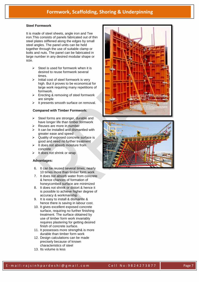
Steel Formwork It is made of steel sheets, angle iron and Tee iron.This consists of panels fabricated out of thin steel plates stiffened along the edges by small steel angles. The panel units can be held together through the use of suitable clamp or bolts and nuts. The panel can be fabricated in large number in any desired modular shape or size.
Steel is used for formwork when it is desired to reuse formwork several times.
Initial cost of steel formwork is very high. But it proves to be economical for large work requiring many repetitions of formwork.
Erecting & removing of steel formwork are simple
It presents smooth surface on removal.
Compared with Timber Formwork:
Steel forms are stronger, durable and have longer life than timber formwork
Reuses are more in number It can be installed and dismantled with
greater ease and speed Quality of exposed concrete surface is
good and need no further treatment It does not absorb moisture from
concrete It does not shrink or wrap
Advantages:
6. It can be reused several times, nearly
10 times more than timber form work 7. It does not absorb water from concrete
& hence chances of formation of honeycombed surface are minimized
8. It does not shrink or distort & hence it is possible to achieve higher degree of accuracy & workmanship
9. It is easy to install & dismantle & hence there is saving in labour cost.
10. It gives excellent exposed concrete surface, requiring no further finishing treatment. The surface obtained by use of timber form work invariably requires plastering for getting desired finish of concrete surface.
11. It possesses more strength& is more durable than timber form work
12. Design calculations can be made precisely because of known characteristics of steel
13. Its volume is less
E - m a i l : r a j s i n h p a r d e s h i @ g m a i l . c o m C e l l N o : 9 8 2 4 2 7 3 8 7 7
Page 8
Formwork, Scaffolding, Shoring & Underpinning
Disadvantages:
1. Limited size or shape 2. Excessive loss of heat 3. A very smooth surface will be
produced which would give problems for finishing process
4. Limited fixing
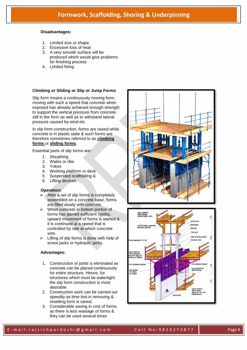
Climbing or Sliding or Slip or Jump Forms
Slip form means a continuously moving form, moving with such a speed that concrete when exposed has already achieved enough strength to support the vertical pressure from concrete still in the form as well as to withstand lateral pressure caused by wind etc.
In slip form construction, forms are raised while concrete is in plastic state & such forms are therefore sometimes referred to as climbing forms or sliding forms.
Essential parts of slip forms are:
1. Sheathing 2. Wales or ribs 3. Yokes 4. Working platform or deck 5. Suspended scaffolding & 6. Lifting devices
Operation: After a set of slip forms is completely
assembled on a concrete base, forms are filled slowly with concrete.
When concrete in bottom portion of forms has gained sufficient rigidity, upward movement of forms is started & it is continued at a speed that is controlled by rate at which concrete sets.
Lifting of slip forms is done with help of screw jacks or hydraulic jacks.
Advantages:
1. Construction of joints is eliminated as concrete can be placed continuously for entire structure. Hence, for structures which must be watertight, the slip form construction is most desirable
2. Construction work can be carried out speedily as time lost in removing & resetting form is saved.
3. Considerable saving in cost of forms as there is less wastage of forms & they can be used several times
E - m a i l : r a j s i n h p a r d e s h i @ g m a i l . c o m C e l l N o : 9 8 2 4 2 7 3 8 7 7
Page 9
Formwork, Scaffolding, Shoring & Underpinning
4. Minimum consumption of timber and steel plates.
5. Total elimination of traditional scaffolding
6. Minimum requirements of carpenters for assembling.
7. It gives a monolithic structure. 8. The concrete surfaces can be treated
and finished while concrete is green, 9. Depending on the weather conditions,
it is possible to achieve a vertical rise to the tune of 4 to 5 m in summer and 2 to 3 m in winter.
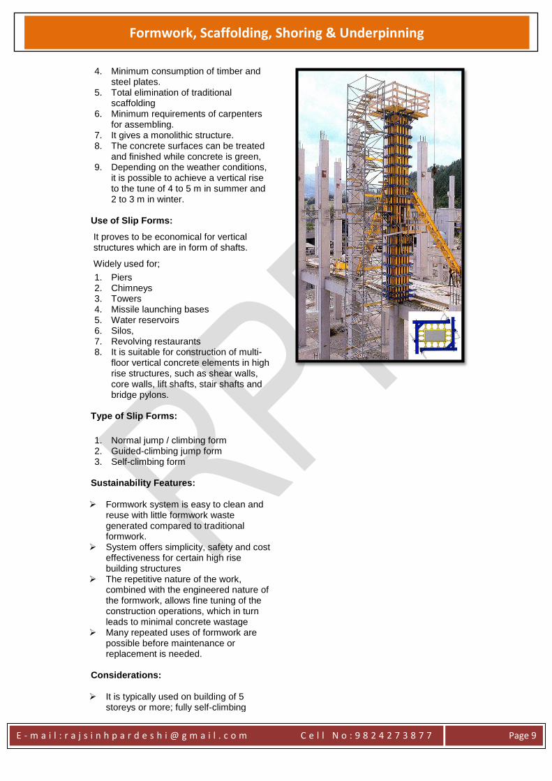
Use of Slip Forms:
It proves to be economical for vertical structures which are in form of shafts.
Widely used for;
1. Piers 2. Chimneys 3. Towers 4. Missile launching bases 5. Water reservoirs 6. Silos, 7. Revolving restaurants 8. It is suitable for construction of multi-
floor vertical concrete elements in high rise structures, such as shear walls, core walls, lift shafts, stair shafts and bridge pylons.
Type of Slip Forms:
1. Normal jump / climbing form 2. Guided-climbing jump form 3. Self-climbing form
Sustainability Features: Formwork system is easy to clean and
reuse with little formwork waste generated compared to traditional formwork.
System offers simplicity, safety and cost effectiveness for certain high rise building structures
The repetitive nature of the work, combined with the engineered nature of the formwork, allows fine tuning of the construction operations, which in turn leads to minimal concrete wastage
Many repeated uses of formwork are possible before maintenance or replacement is needed.
Considerations:
It is typically used on building of 5
storeys or more; fully self-climbing
E - m a i l : r a j s i n h p a r d e s h i @ g m a i l . c o m C e l l N o : 9 8 2 4 2 7 3 8 7 7
Page 10
Formwork, Scaffolding, Shoring & Underpinning
systems are generally used on structures with more than 20 floor levels.
Assembly and lifting operations for self-climbing formwork systems require personnel to be comprehensively trained to ensure competence.
The raising operation must be carefully planned and co-ordinated, and access to the working area during lifting should be restricted to essential personnel.
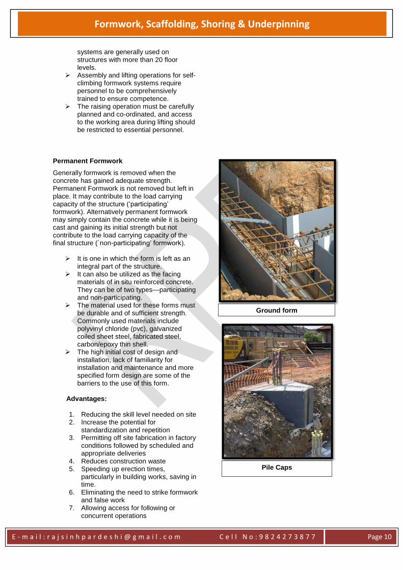
Permanent Formwork
Generally formwork is removed when the concrete has gained adequate strength. Permanent Formwork is not removed but left in place. It may contribute to the load carrying capacity of the structure (‘participating’ formwork). Alternatively permanent formwork may simply contain the concrete while it is being cast and gaining its initial strength but not contribute to the load carrying capacity of the final structure (´non-participating’ formwork).
It is one in which the form is left as an integral part of the structure.
It can also be utilized as the facing materials of in situ reinforced concrete. They can be of two types—participating and non-participating.
The material used for these forms must be durable and of sufficient strength. Commonly used materials include polyvinyl chloride (pvc), galvanized coiled sheet steel, fabricated steel, carbon/epoxy thin shell.
The high initial cost of design and installation, lack of familiarity for installation and maintenance and more specified form design are some of the barriers to the use of this form.
Advantages:
1. Reducing the skill level needed on site 2. Increase the potential for
standardization and repetition 3. Permitting off site fabrication in factory
conditions followed by scheduled and appropriate deliveries
4. Reduces construction waste 5. Speeding up erection times,
particularly in building works, saving in time.
6. Eliminating the need to strike formwork and false work
7. Allowing access for following or concurrent operations
Ground form
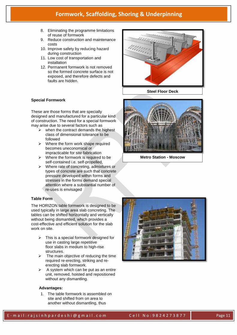
Pile Caps
E - m a i l : r a j s i n h p a r d e s h i @ g m a i l . c o m C e l l N o : 9 8 2 4 2 7 3 8 7 7
Page 11
Formwork, Scaffolding, Shoring & Underpinning
8. Eliminating the programme limitations of reuse of formwork
9. Reduce construction and maintenance costs
10. Improve safety by reducing hazard during construction
11. Low cost of transportation and installation
12. Permanent formwork is not removed so the formed concrete surface is not exposed, and therefore defects and faults are hidden.
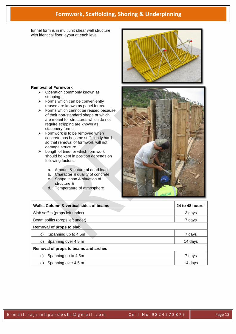
Special Formwork
These are those forms that are specially designed and manufactured for a particular kind of construction. The need for a special formwork may arise due to several factors such as
when the contract demands the highest class of dimensional tolerance to be followed
Where the form work shape required becomes uneconomical or impracticable for site fabrication
Where the formwork is required to be self-contained i.e. self-propelled,
Where rate of concreting, admixtures or types of concrete are such that concrete pressure developed within forms and stresses in the forms demand special attention where a substantial number of re-uses is envisaged
Table Form
The HORIZON table formwork is designed to be used typically in large area slab concreting. The tables can be shifted horizontally and vertically without being dismantled, which provides a cost-effective and efficient solution for the slab work on site.
This is a special formwork designed for use in casting large repetitive floor slabs in medium to high-rise structures.
The main objective of reducing the time required re-erecting, striking and re-erecting slab formwork.
A system which can be put as an entire unit, removed, hoisted and repositioned without any dismantling.
Advantages:
1. The table formwork is assembled on site and shifted from on area to another without dismantling, thus
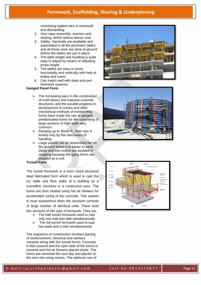
Steel Floor Deck
Metro Station - Moscow
E - m a i l : r a j s i n h p a r d e s h i @ g m a i l . c o m C e l l N o : 9 8 2 4 2 7 3 8 7 7
Page 12
Formwork, Scaffolding, Shoring & Underpinning
minimising added risks in erection9 and dismantling.
2. Very easy assembly, erection and striping, which reduce labour cost.
3. Safety. Handrails are available and assembled in all the perimeter tables, and all these work are done at ground before the tables are put in place.
4. The table height and levelling is quite easy to adjust by means of adjusting props height.
5. The tables are easy to move horizontally and vertically with help of trolley and crane.
6. Can match well with doka and peri formwork systems.
Ganged Panel Form
The increasing pace in the construction of multi-storey and massive concrete structures, and the parallel progress in development of cranes and other mechanical methods of transporting forms have made the use of ganged prefabricated forms for the concreting of large sections of high walls very common.
Ranging up to 30x50 ft., their size is limited only by the mechanics of handling.
Large panels can be assembled flat on the ground where it is easier to work. Delay and lost motion are avoided in stripping because the gang forms are stripped as a unit.
Tunnel Form
The tunnel formwork is a room sized structural
steel fabricated form which is used to cast the
rcc walls and floor slabs of a building as a
monolithic structure in a continuous pour. The
forms are then heated using hot air blowers for
accelerated curing of the concrete. This system
is most economical when the structure consists
of large number of identical units. There exist
two versions of this type of formwork. They are: The half tunnel formwork used to cast
only one wall and slab simultaneously The full tunnel formwork used to cast
two walls and a slab simultaneously The sequence of construction involves placing of reinforcement, electrical and sanitary conduits along with the tunnel forms. Concrete is then poured and the open side of the forms is covered and hot air blowers placed inside. The forms are removed the next day and placed on the next site using cranes. The optimum use of
E - m a i l : r a j s i n h p a r d e s h i @ g m a i l . c o m C e l l N o : 9 8 2 4 2 7 3 8 7 7
Page 13
Formwork, Scaffolding, Shoring & Underpinning
tunnel form is in multiunit shear wall structure with identical floor layout at each level.
Removal of Formwork
Operation commonly known as stripping.
Forms which can be conveniently reused are known as panel forms.
Forms which cannot be reused because of their non-standard shape or which are meant for structures which do not require stripping are known as stationery forms.
Formwork is to be removed when concrete has become sufficiently hard so that removal of formwork will not damage structure.
Length of time for which formwork should be kept in position depends on following factors:
a. Amount & nature of dead load b. Character & quality of concrete c. Shape, span & situation of
structure & d. Temperature of atmosphere
Walls, Column & vertical sides of beams 24 to 48 hours
Slab soffits (props left under) 3 days
Beam soffits (props left under) 7 days
Removal of props to slab
c) Spanning up to 4.5m 7 days
d) Spanning over 4.5 m 14 days
Removal of props to beams and arches
c) Spanning up to 4.5m 7 days
d) Spanning over 4.5 m 14 days
E - m a i l : r a j s i n h p a r d e s h i @ g m a i l . c o m C e l l N o : 9 8 2 4 2 7 3 8 7 7
Page 14
Formwork, Scaffolding, Shoring & Underpinning
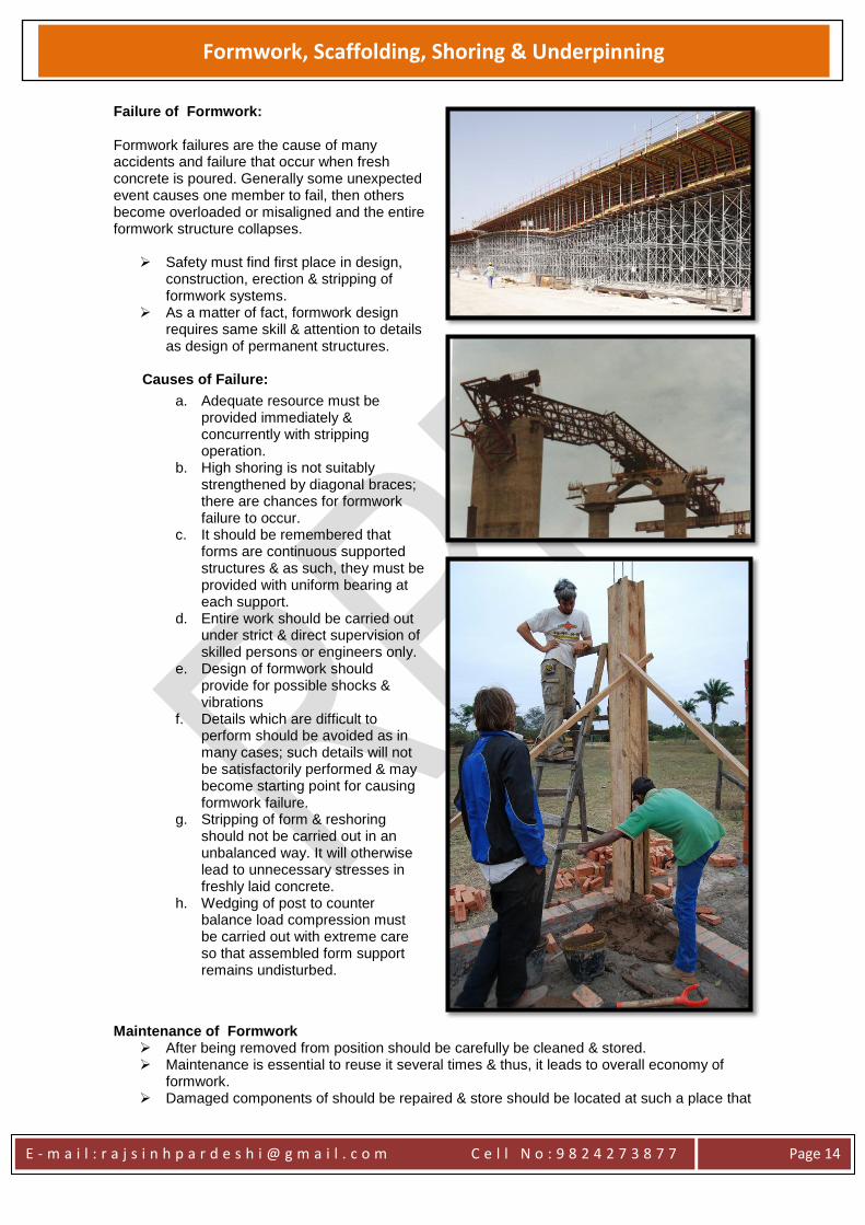
Failure of Formwork: Formwork failures are the cause of many accidents and failure that occur when fresh concrete is poured. Generally some unexpected event causes one member to fail, then others become overloaded or misaligned and the entire formwork structure collapses.
Safety must find first place in design, construction, erection & stripping of formwork systems.
As a matter of fact, formwork design requires same skill & attention to details as design of permanent structures.
Causes of Failure:
a. Adequate resource must be provided immediately & concurrently with stripping operation.
b. High shoring is not suitably strengthened by diagonal braces; there are chances for formwork failure to occur.
c. It should be remembered that forms are continuous supported structures & as such, they must be provided with uniform bearing at each support.
d. Entire work should be carried out under strict & direct supervision of skilled persons or engineers only.
e. Design of formwork should provide for possible shocks & vibrations
f. Details which are difficult to perform should be avoided as in many cases; such details will not be satisfactorily performed & may become starting point for causing formwork failure.
g. Stripping of form & reshoring should not be carried out in an unbalanced way. It will otherwise lead to unnecessary stresses in freshly laid concrete.
h. Wedging of post to counter balance load compression must be carried out with extreme care so that assembled form support remains undisturbed.
Maintenance of Formwork
After being removed from position should be carefully be cleaned & stored. Maintenance is essential to reuse it several times & thus, it leads to overall economy of
formwork. Damaged components of should be repaired & store should be located at such a place that
E - m a i l : r a j s i n h p a r d e s h i @ g m a i l . c o m C e l l N o : 9 8 2 4 2 7 3 8 7 7
Page 15
Formwork, Scaffolding, Shoring & Underpinning
there are minimum chances for wind, rain, moisture etc. to have advance effect on it.
Cost of Formwork For normal works, cost of formwork is about 30% to 40% of the concrete cost For special work, cost of formwork is about 50% to 60% of the concrete cost Formwork cost is controlled by the following factors:
a) Formwork material cost b) Formwork erecting cost c) Formwork removal cost d) Formwork jointing cost (Nails and Cables) e) Labour charges
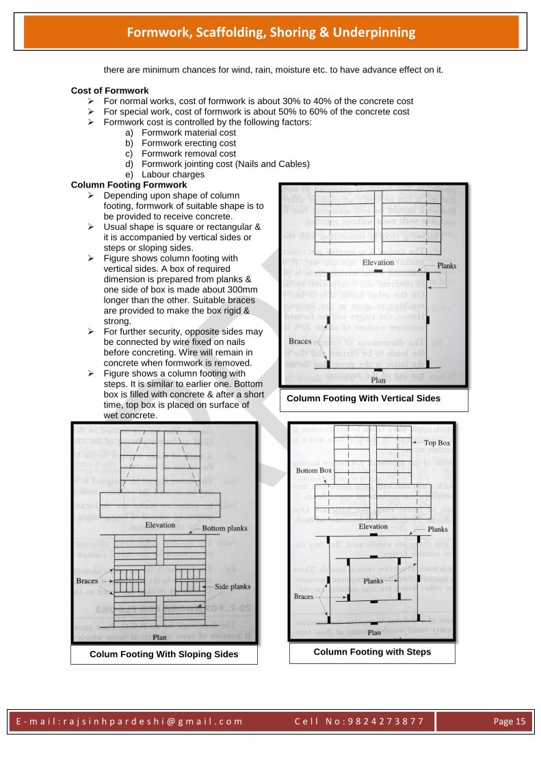
Column Footing Formwork Depending upon shape of column
footing, formwork of suitable shape is to be provided to receive concrete.
Usual shape is square or rectangular & it is accompanied by vertical sides or steps or sloping sides.
Figure shows column footing with vertical sides. A box of required dimension is prepared from planks & one side of box is made about 300mm longer than the other. Suitable braces are provided to make the box rigid & strong.
For further security, opposite sides may be connected by wire fixed on nails before concreting. Wire will remain in concrete when formwork is removed.
Figure shows a column footing with steps. It is similar to earlier one. Bottom box is filled with concrete & after a short time, top box is placed on surface of wet concrete.
Column Footing With Vertical Sides
Column Footing with Steps Colum Footing With Sloping Sides
E - m a i l : r a j s i n h p a r d e s h i @ g m a i l . c o m C e l l N o : 9 8 2 4 2 7 3 8 7 7
Page 16
Formwork, Scaffolding, Shoring & Underpinning
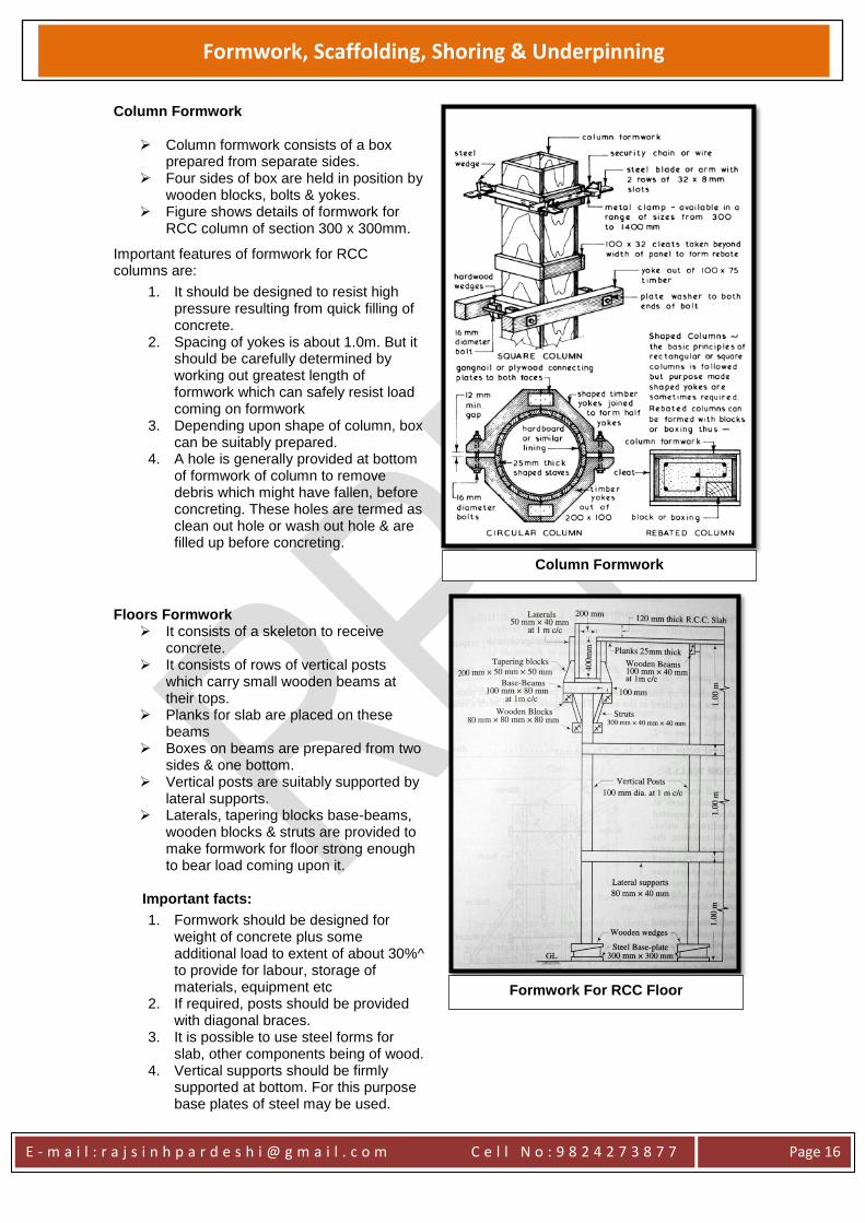
Column Formwork
Column formwork consists of a box prepared from separate sides.
Four sides of box are held in position by wooden blocks, bolts & yokes.
Figure shows details of formwork for RCC column of section 300 x 300mm.
Important features of formwork for RCC columns are:
1. It should be designed to resist high pressure resulting from quick filling of concrete.
2. Spacing of yokes is about 1.0m. But it should be carefully determined by working out greatest length of formwork which can safely resist load coming on formwork
3. Depending upon shape of column, box can be suitably prepared.
4. A hole is generally provided at bottom of formwork of column to remove debris which might have fallen, before concreting. These holes are termed as clean out hole or wash out hole & are filled up before concreting.
Floors Formwork
It consists of a skeleton to receive concrete.
It consists of rows of vertical posts which carry small wooden beams at their tops.
Planks for slab are placed on these beams
Boxes on beams are prepared from two sides & one bottom.
Vertical posts are suitably supported by lateral supports.
Laterals, tapering blocks base-beams, wooden blocks & struts are provided to make formwork for floor strong enough to bear load coming upon it.
Important facts:
1. Formwork should be designed for weight of concrete plus some additional load to extent of about 30%^ to provide for labour, storage of materials, equipment etc
2. If required, posts should be provided with diagonal braces.
3. It is possible to use steel forms for slab, other components being of wood.
4. Vertical supports should be firmly supported at bottom. For this purpose base plates of steel may be used.
Formwork For RCC Floor
Column Formwork
E - m a i l : r a j s i n h p a r d e s h i @ g m a i l . c o m C e l l N o : 9 8 2 4 2 7 3 8 7 7
Page 17
Formwork, Scaffolding, Shoring & Underpinning
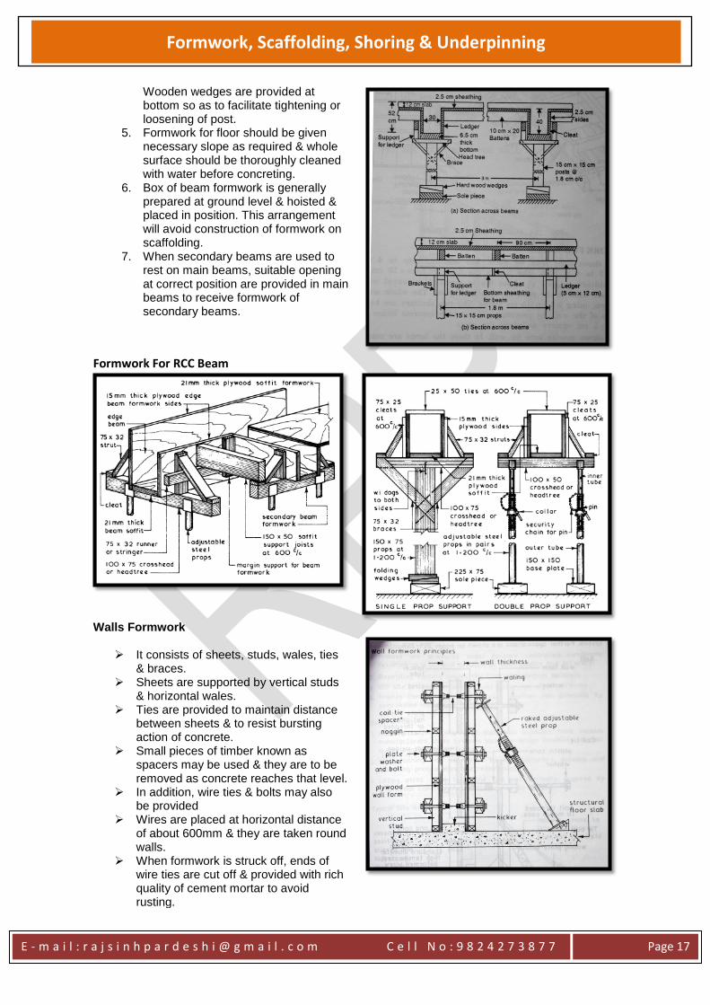
Wooden wedges are provided at bottom so as to facilitate tightening or loosening of post.
5. Formwork for floor should be given necessary slope as required & whole surface should be thoroughly cleaned with water before concreting.
6. Box of beam formwork is generally prepared at ground level & hoisted & placed in position. This arrangement will avoid construction of formwork on scaffolding.
7. When secondary beams are used to rest on main beams, suitable opening at correct position are provided in main beams to receive formwork of secondary beams.
Formwork For RCC Beam
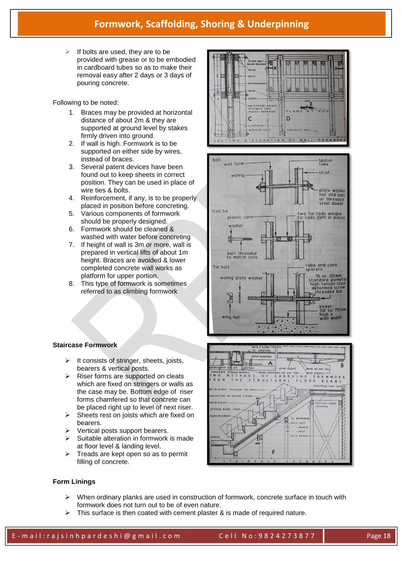
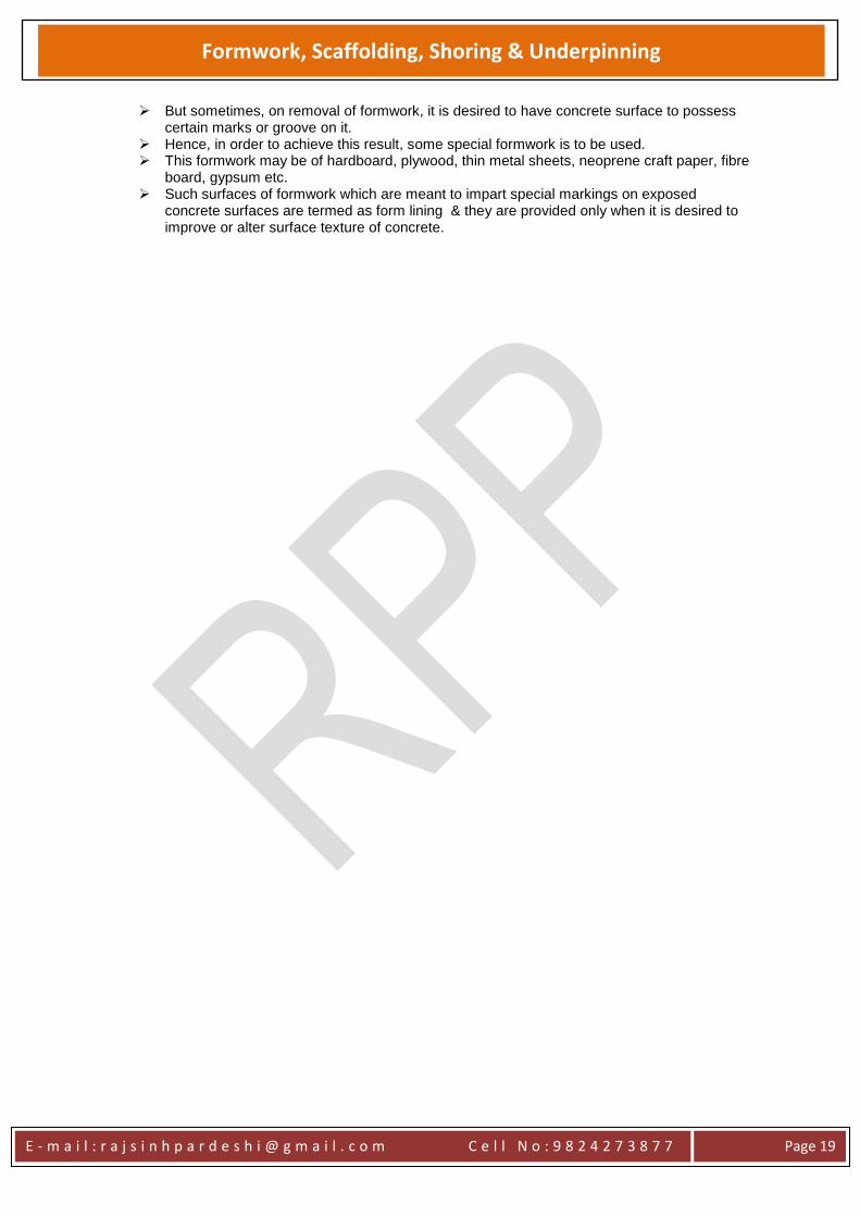
Walls Formwork
It consists of sheets, studs, wales, ties & braces.
Sheets are supported by vertical studs & horizontal wales.
Ties are provided to maintain distance between sheets & to resist bursting action of concrete.
Small pieces of timber known as spacers may be used & they are to be removed as concrete reaches that level.
In addition, wire ties & bolts may also be provided
Wires are placed at horizontal distance of about 600mm & they are taken round walls.
When formwork is struck off, ends of wire ties are cut off & provided with rich quality of cement mortar to avoid rusting.
E - m a i l : r a j s i n h p a r d e s h i @ g m a i l . c o m C e l l N o : 9 8 2 4 2 7 3 8 7 7
Page 18
Formwork, Scaffolding, Shoring & Underpinning
If bolts are used, they are to be provided with grease or to be embodied in cardboard tubes so as to make their removal easy after 2 days or 3 days of pouring concrete.
Following to be noted:
1. Braces may be provided at horizontal distance of about 2m & they are supported at ground level by stakes firmly driven into ground.
2. If wall is high. Formwork is to be supported on either side by wires, instead of braces.
3. Several patent devices have been found out to keep sheets in correct position. They can be used in place of wire ties & bolts.
4. Reinforcement, if any, is to be properly placed in position before concreting.
5. Various components of formwork should be properly designed.
6. Formwork should be cleaned & washed with water before concreting
7. If height of wall is 3m or more, wall is prepared in vertical lifts of about 1m height. Braces are avoided & lower completed concrete wall works as platform for upper portion.
8. This type of formwork is sometimes referred to as climbing formwork
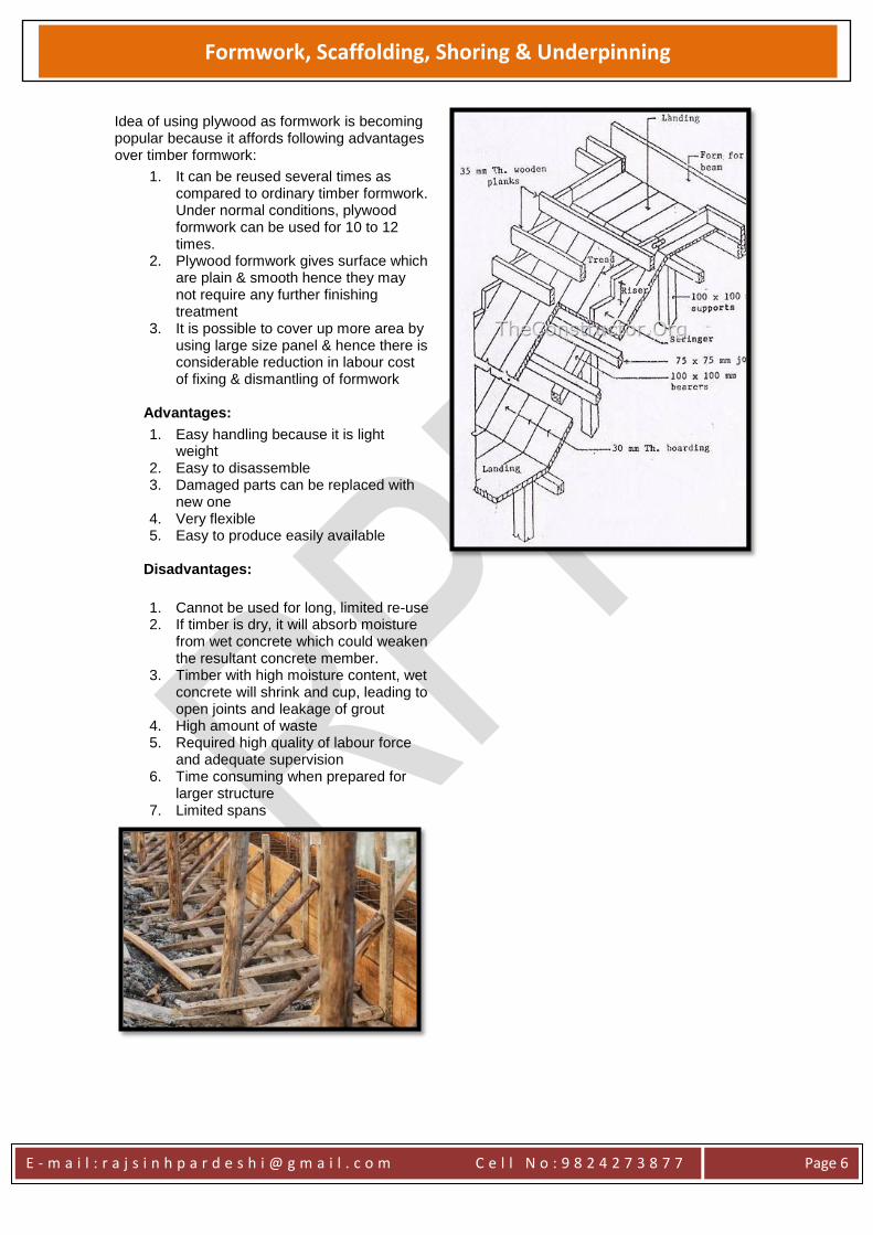
Staircase Formwork
It consists of stringer, sheets, joists, bearers & vertical posts.
Riser forms are supported on cleats which are fixed on stringers or walls as the case may be. Bottom edge of riser forms chamfered so that concrete can be placed right up to level of next riser.
Sheets rest on joists which are fixed on bearers.
Vertical posts support bearers. Suitable alteration in formwork is made
at floor level & landing level. Treads are kept open so as to permit
filling of concrete.
Form Linings
When ordinary planks are used in construction of formwork, concrete surface in touch with formwork does not turn out to be of even nature.
This surface is then coated with cement plaster & is made of required nature.
E - m a i l : r a j s i n h p a r d e s h i @ g m a i l . c o m C e l l N o : 9 8 2 4 2 7 3 8 7 7
Page 19
Formwork, Scaffolding, Shoring & Underpinning
But sometimes, on removal of formwork, it is desired to have concrete surface to possess certain marks or groove on it.
Hence, in order to achieve this result, some special formwork is to be used. This formwork may be of hardboard, plywood, thin metal sheets, neoprene craft paper, fibre
board, gypsum etc. Such surfaces of formwork which are meant to impart special markings on exposed
concrete surfaces are termed as form lining & they are provided only when it is desired to improve or alter surface texture of concrete.
E - m a i l : r a j s i n h p a r d e s h i @ g m a i l . c o m C e l l N o : 9 8 2 4 2 7 3 8 7 7
Page 20
Formwork, Scaffolding, Shoring & Underpinning
SCAFFOLDING
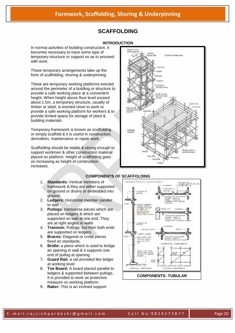
INTRODUCTION In normal activities of building construction, it becomes necessary to have some type of temporary structure or support so as to proceed with work. These temporary arrangements take up the form of scaffolding, shoring & underpinning. These are temporary working platforms erected around the perimeter of a building or structure to provide a safe working place at a convenient height. When height above floor level exceed about 1.5m, a temporary structure, usually of timber or steel, is erected close to work to provide a safe working platform for workers & to provide limited space for storage of plant & building materials. Temporary framework is known as scaffolding or simply scaffold & it is useful in construction, demolition, maintenance or repair work. Scaffolding should be stable & strong enough to support workmen & other construction material placed on platform. Height of scaffolding goes on increasing as height of construction increases.
COMPONENTS OF SCAFFOLDING
1. Standards: Vertical members of framework & they are either supported on ground or drums or embedded into ground.
2. Ledgers: Horizontal member parallel to wall
3. Putlogs: transverse pieces which are placed on ledgers & which are supported on wall at one end. They are at right angles to walls
4. Transom: Putlogs, but their both ends are supported on ledgers.
5. Braces: Diagonal or cross pieces fixed on standards.
6. Bridle: a piece which is used to bridge an opening in wall & it supports one end of putlog at opening
7. Guard Rail: a rail provided like ledger at working level
8. Toe Board: A board placed parallel to ledgers & supported between putlogs. It is provided to work as protective measure on working platform.
9. Raker: This is an inclined support
COMPONENTS- TUBULAR
SCAFFOLD
E - m a i l : r a j s i n h p a r d e s h i @ g m a i l . c o m C e l l N o : 9 8 2 4 2 7 3 8 7 7
Page 21
Formwork, Scaffolding, Shoring & Underpinning
TYPES OF SCAFFOLDING Following are types of scaffolding:
1. Single scaffolding or brick layer’s scaffolding
2. Double scaffolding or mason’s scaffolding
3. Cantilever or Needle Scaffolding 4. Suspended Scaffolding 5. Ladder & Trestle Scaffolding 6. Steel Scaffolding 7. Patented Scaffolding 8. Birdcage Scaffolding
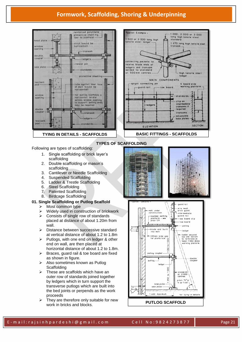
01. Single Scaffolding or Putlog Scaffold
Most common type Widely used in construction of brickwork Consists of single row of standards
placed at distance of about 1.20m from wall.
Distance between successive standard at vertical distance of about 1.2 to 1.8m
Putlogs, with one end on ledger & other end on wall, are then placed at horizontal distance of about 1.2 to 1.8m.
Braces, guard rail & toe board are fixed as shown in figure.
Also sometimes known as Putlog Scaffolding
These are scaffolds which have an outer row of standards joined together by ledgers which in turn support the transverse putlogs which are built into the bed joints or perpends as the work proceeds
They are therefore only suitable for new work in bricks and blocks.
TYING IN DETAILS - SCAFFOLDS BASIC FITTINGS - SCAFFOLDS
PUTLOG SCAFFOLD
E - m a i l : r a j s i n h p a r d e s h i @ g m a i l . c o m C e l l N o : 9 8 2 4 2 7 3 8 7 7
Page 22
Formwork, Scaffolding, Shoring & Underpinning
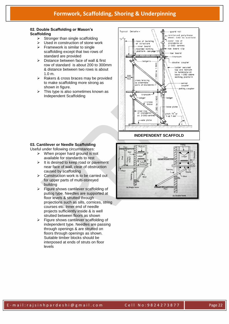
02. Double Scaffolding or Mason’s Scaffolding
Stronger than single scaffolding Used in construction of stone work Framework is similar to single
scaffolding except that two rows of standard are provided
Distance between face of wall & first row of standard is about 200 to 300mm & distance between two rows is about 1.0 m.
Rakers & cross braces may be provided to make scaffolding more strong as shown in figure.
This type is also sometimes known as Independent Scaffolding
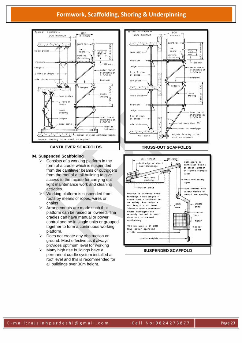
03. Cantilever or Needle Scaffolding Useful under following circumstances:
When proper hard ground is not available for standards to rest
It is desired to keep road or pavement near face of wall, clear of obstruction caused by scaffolding
Construction work is to be carried out for upper parts of multi-storeyed building
Figure shows cantilever scaffolding of putlog type. Needles are supported at floor levels & strutted through projections such as sills, cornices, string courses etc. Inner end of needle projects sufficiently inside & is well strutted between floors as shown
Figure shows cantilever scaffolding of independent type. Needles are passing through openings & are strutted on floors through openings as shown. Suitable timber blocks should be interposed at ends of struts on floor levels
INDEPENDENT SCAFFOLD
E - m a i l : r a j s i n h p a r d e s h i @ g m a i l . c o m C e l l N o : 9 8 2 4 2 7 3 8 7 7
Page 23
Formwork, Scaffolding, Shoring & Underpinning
04. Suspended Scaffolding Consists of a working platform in the
form of a cradle which is suspended from the cantilever beams or outriggers from the roof of a tall building to give access to the façade for carrying out light maintenance work and cleaning activities.
Working platform is suspended from roofs by means of ropes, wires or chains
Arrangements are made such that platform can be raised or lowered. The cradles can have manual or power control and be in single units or grouped together to form a continuous working platform.
Does not create any obstruction on ground. Most effective as it always provides optimum level for working
Many high rise buildings have a permanent cradle system installed at roof level and this is recommended for all buildings over 30m height.
CANTILEVER SCAFFOLDS TRUSS-OUT SCAFFOLDS
SUSPENDED SCAFFOLD
E - m a i l : r a j s i n h p a r d e s h i @ g m a i l . c o m C e l l N o : 9 8 2 4 2 7 3 8 7 7
Page 24
Formwork, Scaffolding, Shoring & Underpinning
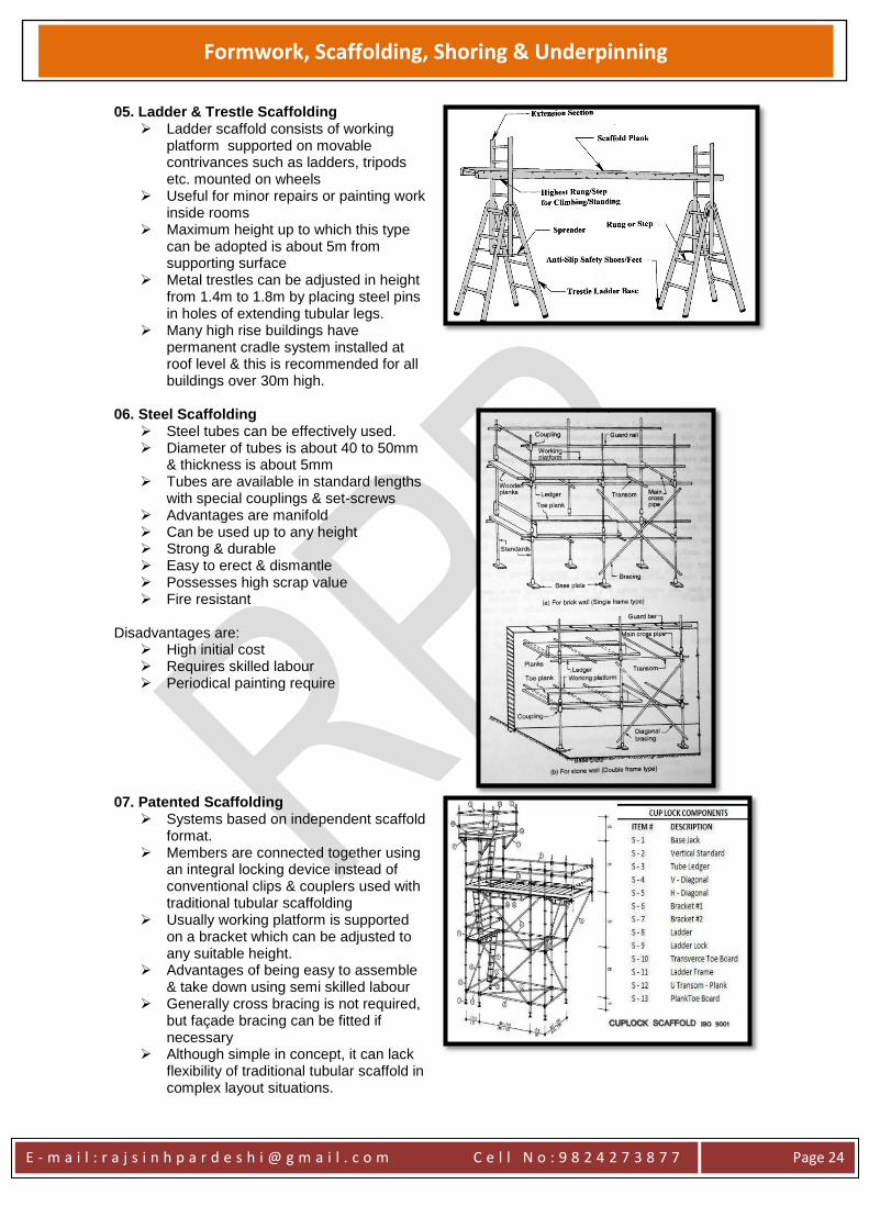
05. Ladder & Trestle Scaffolding Ladder scaffold consists of working
platform supported on movable contrivances such as ladders, tripods etc. mounted on wheels
Useful for minor repairs or painting work inside rooms
Maximum height up to which this type can be adopted is about 5m from supporting surface
Metal trestles can be adjusted in height from 1.4m to 1.8m by placing steel pins in holes of extending tubular legs.
Many high rise buildings have permanent cradle system installed at roof level & this is recommended for all buildings over 30m high.
06. Steel Scaffolding Steel tubes can be effectively used. Diameter of tubes is about 40 to 50mm
& thickness is about 5mm Tubes are available in standard lengths
with special couplings & set-screws Advantages are manifold Can be used up to any height Strong & durable Easy to erect & dismantle Possesses high scrap value Fire resistant
Disadvantages are:
High initial cost Requires skilled labour Periodical painting require
07. Patented Scaffolding
Systems based on independent scaffold format.
Members are connected together using an integral locking device instead of conventional clips & couplers used with traditional tubular scaffolding
Usually working platform is supported on a bracket which can be adjusted to any suitable height.
Advantages of being easy to assemble & take down using semi skilled labour
Generally cross bracing is not required, but façade bracing can be fitted if necessary
Although simple in concept, it can lack flexibility of traditional tubular scaffold in complex layout situations.
E - m a i l : r a j s i n h p a r d e s h i @ g m a i l . c o m C e l l N o : 9 8 2 4 2 7 3 8 7 7
Page 25
Formwork, Scaffolding, Shoring & Underpinning
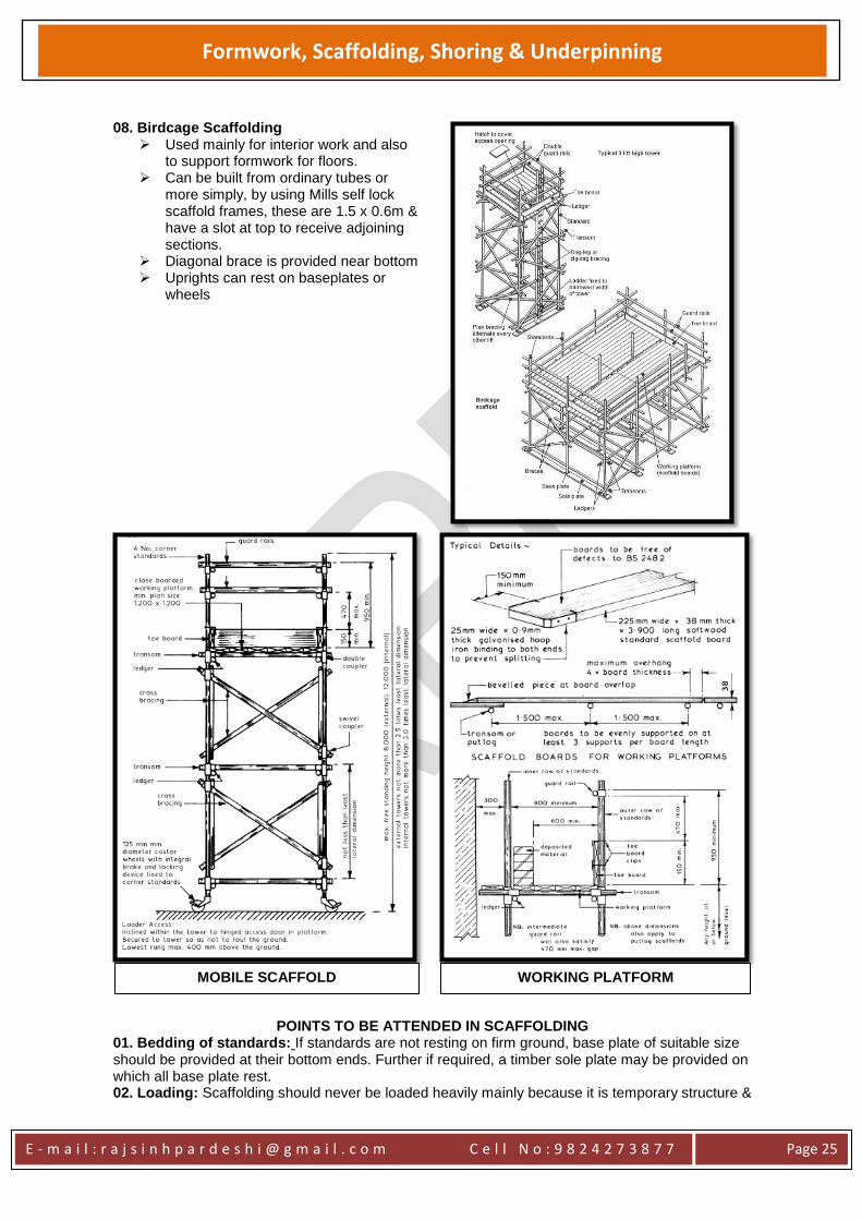
08. Birdcage Scaffolding
Used mainly for interior work and also to support formwork for floors.
Can be built from ordinary tubes or more simply, by using Mills self lock scaffold frames, these are 1.5 x 0.6m & have a slot at top to receive adjoining sections.
Diagonal brace is provided near bottom Uprights can rest on baseplates or
wheels
POINTS TO BE ATTENDED IN SCAFFOLDING
01. Bedding of standards: If standards are not resting on firm ground, base plate of suitable size should be provided at their bottom ends. Further if required, a timber sole plate may be provided on which all base plate rest. 02. Loading: Scaffolding should never be loaded heavily mainly because it is temporary structure &
MOBILE SCAFFOLD WORKING PLATFORM
E - m a i l : r a j s i n h p a r d e s h i @ g m a i l . c o m C e l l N o : 9 8 2 4 2 7 3 8 7 7
Page 26
Formwork, Scaffolding, Shoring & Underpinning
in case of single scaffolding, one of ends of putlogs rests on green surface of masonry 03: Tying in Scaffolding: It is necessary to tie back scaffolding with building at suitable levels. This can be achieved in different ways:
a. Vertical or Horizontal tube is, wedged by means of reveal pin, may be provided in opening & one of ends of putlog may be coupled with this tube.
b. Tube may be provided across opening inside wall & one of ends of putlogs may be coupled with this tube.
c. Rakers, strutting from ground level, may be provided. 04. Raising: As work proceeds, standards are suitably lengthened & fresh ledgers & putlogs are inserted. Working platforms are then shifted to new levels. 05. Finishing: After scaffolding is removed, holes of putlogs in wall should be immediately filled up. 06. Spacing of Standards: Loading on scaffolding decides spacing of standards. It is less for heavy & more for light loading. Maximum spacing is about 3.0m. 07. Miscellaneous Structure: Scaffolding of special types should be built for miscellaneous structures such as chimney, towers, domes etc.
E - m a i l : r a j s i n h p a r d e s h i @ g m a i l . c o m C e l l N o : 9 8 2 4 2 7 3 8 7 7
Page 27
Formwork, Scaffolding, Shoring & Underpinning
SHORING
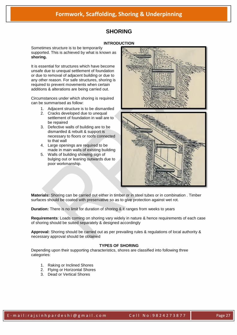
INTRODUCTION Sometimes structure is to be temporarily supported. This is achieved by what is known as shoring. It is essential for structures which have become unsafe due to unequal settlement of foundation or due to removal of adjacent building or due to any other reason. For safe structures, shoring is required to prevent movements when certain additions & alterations are being carried out. Circumstances under which shoring is required can be summarised as follow:
1. Adjacent structure is to be dismantled 2. Cracks developed due to unequal
settlement of foundation in wall are to be repaired
3. Defective walls of building are to be dismantled & rebuilt & support is necessary to floors or roofs connected to that wall
4. Large openings are required to be made in main walls of existing building
5. Walls of building showing sign of bulging out or leaning outwards due to poor workmanship.
Materials: Shoring can be carried out either in timber or in steel tubes or in combination . Timber surfaces should be coated with preservative so as to give protection against wet rot. Duration: There is no limit for duration of shoring & it ranges from weeks to years Requirements: Loads coming on shoring vary widely in nature & hence requirements of each case of shoring should be suited separately & designed accordingly Approval: Shoring should be carried out as per prevailing rules & regulations of local authority & necessary approval should be obtained
TYPES OF SHORING
Depending upon their supporting characteristics, shores are classified into following three categories:
1. Raking or Inclined Shores 2. Flying or Horizontal Shores 3. Dead or Vertical Shores
E - m a i l : r a j s i n h p a r d e s h i @ g m a i l . c o m C e l l N o : 9 8 2 4 2 7 3 8 7 7
Page 28
Formwork, Scaffolding, Shoring & Underpinning
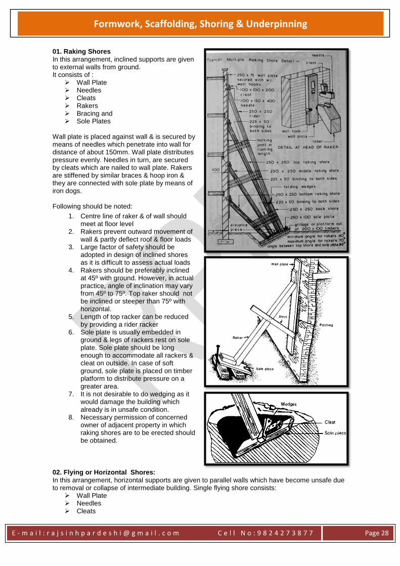
01. Raking Shores In this arrangement, inclined supports are given to external walls from ground. It consists of :
Wall Plate Needles Cleats Rakers Bracing and Sole Plates
Wall plate is placed against wall & is secured by means of needles which penetrate into wall for distance of about 150mm. Wall plate distributes pressure evenly. Needles in turn, are secured by cleats which are nailed to wall plate. Rakers are stiffened by similar braces & hoop iron & they are connected with sole plate by means of iron dogs. Following should be noted:
1. Centre line of raker & of wall should meet at floor level
2. Rakers prevent outward movement of wall & partly deflect roof & floor loads
3. Large factor of safety should be adopted in design of inclined shores as it is difficult to assess actual loads
4. Rakers should be preferably inclined at 45º with ground. However, in actual practice, angle of inclination may vary from 45º to 75º. Top raker should not be inclined or steeper than 75º with horizontal.
5. Length of top racker can be reduced by providing a rider racker
6. Sole plate is usually embedded in ground & legs of rackers rest on sole plate. Sole plate should be long enough to accommodate all rackers & cleat on outside. In case of soft ground, sole plate is placed on timber platform to distribute pressure on a greater area.
7. It is not desirable to do wedging as it would damage the building which already is in unsafe condition.
8. Necessary permission of concerned owner of adjacent property in which raking shores are to be erected should be obtained.
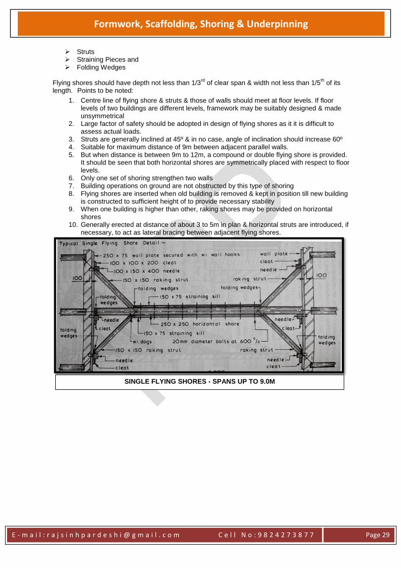
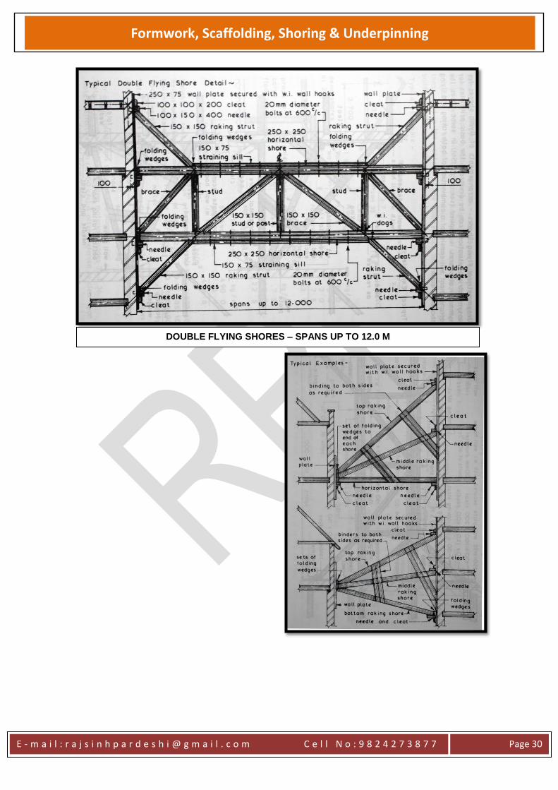
02. Flying or Horizontal Shores: In this arrangement, horizontal supports are given to parallel walls which have become unsafe due to removal or collapse of intermediate building. Single flying shore consists:
Wall Plate Needles Cleats
E - m a i l : r a j s i n h p a r d e s h i @ g m a i l . c o m C e l l N o : 9 8 2 4 2 7 3 8 7 7
Page 29
Formwork, Scaffolding, Shoring & Underpinning
Struts Straining Pieces and Folding Wedges
Flying shores should have depth not less than 1/3
rd of clear span & width not less than 1/5
th of its
length. Points to be noted:
1. Centre line of flying shore & struts & those of walls should meet at floor levels. If floor levels of two buildings are different levels, framework may be suitably designed & made unsymmetrical
2. Large factor of safety should be adopted in design of flying shores as it it is difficult to assess actual loads.
3. Struts are generally inclined at 45º & in no case, angle of inclination should increase 60º 4. Suitable for maximum distance of 9m between adjacent parallel walls. 5. But when distance is between 9m to 12m, a compound or double flying shore is provided.
It should be seen that both horizontal shores are symmetrically placed with respect to floor levels.
6. Only one set of shoring strengthen two walls 7. Building operations on ground are not obstructed by this type of shoring 8. Flying shores are inserted when old building is removed & kept in position till new building
is constructed to sufficient height of to provide necessary stability 9. When one building is higher than other, raking shores may be provided on horizontal
shores 10. Generally erected at distance of about 3 to 5m in plan & horizontal struts are introduced, if
necessary, to act as lateral bracing between adjacent flying shores.
SINGLE FLYING SHORES - SPANS UP TO 9.0M
E - m a i l : r a j s i n h p a r d e s h i @ g m a i l . c o m C e l l N o : 9 8 2 4 2 7 3 8 7 7
Page 30
Formwork, Scaffolding, Shoring & Underpinning
DOUBLE FLYING SHORES – SPANS UP TO 12.0 M
E - m a i l : r a j s i n h p a r d e s h i @ g m a i l . c o m C e l l N o : 9 8 2 4 2 7 3 8 7 7
Page 31
Formwork, Scaffolding, Shoring & Underpinning
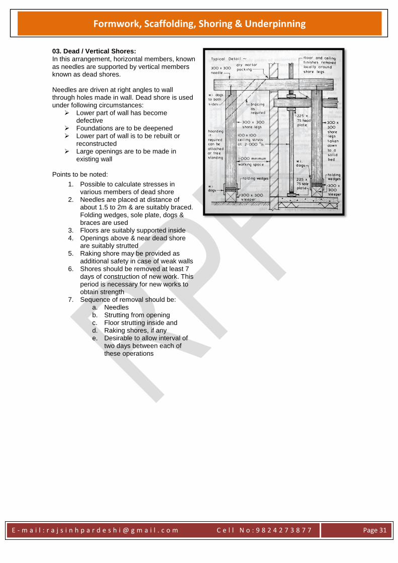
03. Dead / Vertical Shores: In this arrangement, horizontal members, known as needles are supported by vertical members known as dead shores. Needles are driven at right angles to wall through holes made in wall. Dead shore is used under following circumstances:
Lower part of wall has become defective
Foundations are to be deepened Lower part of wall is to be rebuilt or
reconstructed Large openings are to be made in
existing wall Points to be noted:
1. Possible to calculate stresses in various members of dead shore
2. Needles are placed at distance of about 1.5 to 2m & are suitably braced. Folding wedges, sole plate, dogs & braces are used
3. Floors are suitably supported inside 4. Openings above & near dead shore
are suitably strutted 5. Raking shore may be provided as
additional safety in case of weak walls 6. Shores should be removed at least 7
days of construction of new work. This period is necessary for new works to obtain strength
7. Sequence of removal should be: a. Needles b. Strutting from opening c. Floor strutting inside and d. Raking shores, if any e. Desirable to allow interval of
two days between each of these operations
E - m a i l : r a j s i n h p a r d e s h i @ g m a i l . c o m C e l l N o : 9 8 2 4 2 7 3 8 7 7
Page 32
Formwork, Scaffolding, Shoring & Underpinning
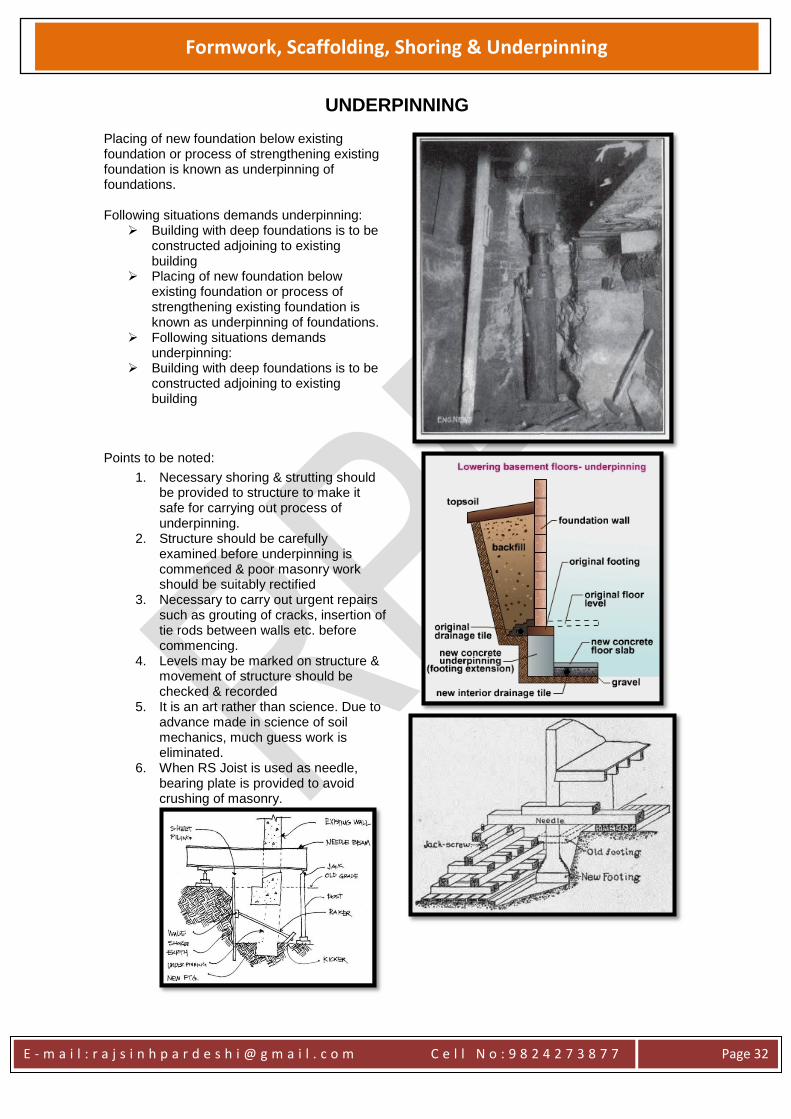
UNDERPINNING Placing of new foundation below existing foundation or process of strengthening existing foundation is known as underpinning of foundations. Following situations demands underpinning:
Building with deep foundations is to be constructed adjoining to existing building
Placing of new foundation below existing foundation or process of strengthening existing foundation is known as underpinning of foundations.
Following situations demands underpinning:
Building with deep foundations is to be constructed adjoining to existing building
Points to be noted:
1. Necessary shoring & strutting should be provided to structure to make it safe for carrying out process of underpinning.
2. Structure should be carefully examined before underpinning is commenced & poor masonry work should be suitably rectified
3. Necessary to carry out urgent repairs such as grouting of cracks, insertion of tie rods between walls etc. before commencing.
4. Levels may be marked on structure & movement of structure should be checked & recorded
5. It is an art rather than science. Due to advance made in science of soil mechanics, much guess work is eliminated.
6. When RS Joist is used as needle, bearing plate is provided to avoid crushing of masonry.
E - m a i l : r a j s i n h p a r d e s h i @ g m a i l . c o m C e l l N o : 9 8 2 4 2 7 3 8 7 7
Page 33
Formwork, Scaffolding, Shoring & Underpinning
METHOD OF UNDERPINNING
1. Pit Method 2. Pile Method 3. Miscellaneous Methods
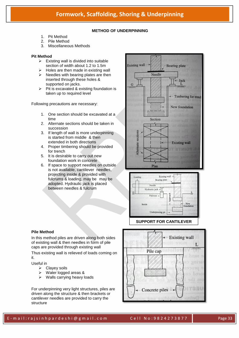
Pit Method Existing wall is divided into suitable
section of width about 1.2 to 1.5m Holes are then made in existing wall Needles with bearing plates are then
inserted through these holes & supported on jacks.
Pit is excavated & existing foundation is taken up to required level
Following precautions are necessary:
1. One section should be excavated at a
time 2. Alternate sections should be taken in
succession 3. If length of wall is more underpinning
is started from middle & then extended in both directions
4. Proper timbering should be provided for trench
5. It is desirable to carry out new foundation work in concrete
6. If space to support needles on outside is not available, cantilever needles, projecting inside & provided with fulcrums & loading, may be may be adopted. Hydraulic jack is placed between needles & fulcrum
Pile Method
In this method piles are driven along both sides of existing wall & then needles in form of pile caps are provided through existing wall
Thus existing wall is relieved of loads coming on it.
Useful in Clayey soils Water logged areas & Walls carrying heavy loads
For underpinning very light structures, piles are driven along the structure & then brackets or cantilever needles are provided to carry the structure
SUPPORT FOR CANTILEVER
E - m a i l : r a j s i n h p a r d e s h i @ g m a i l . c o m C e l l N o : 9 8 2 4 2 7 3 8 7 7
Page 34
Formwork, Scaffolding, Shoring & Underpinning
Miscellaneous Method
Following are some specialised underpinning methods which may sometimes be successfully adopted:
1. Cement Grouting 2. Chemical Consolidation 3. Freezing 4. Vibro flotation
1. Cement Grouting Used to restore slab or pavement which has settled Operation is simple Holes are drilled in slab & cement grout is forced under pressure through these holes Pressure is maintained until cement grout has set
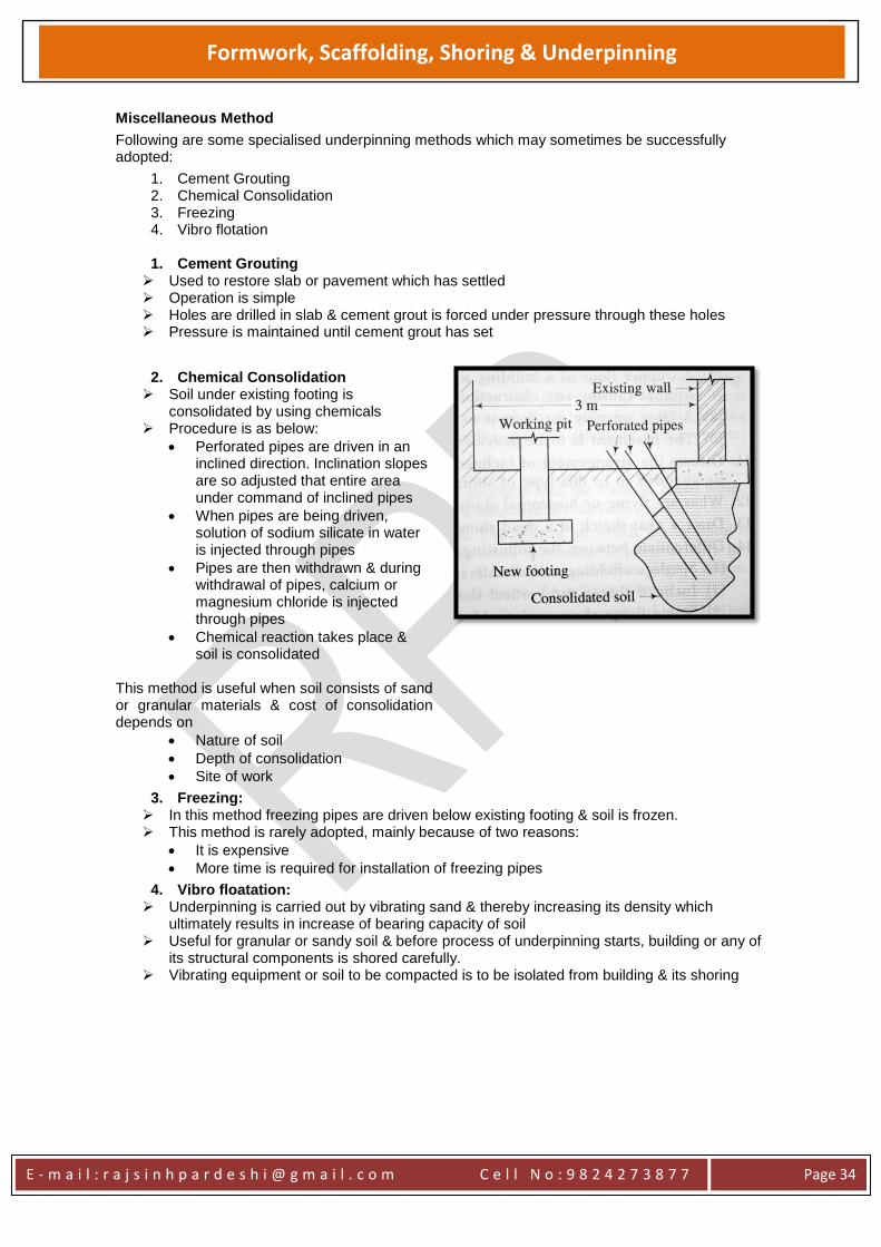
2. Chemical Consolidation Soil under existing footing is
consolidated by using chemicals Procedure is as below:
Perforated pipes are driven in an inclined direction. Inclination slopes are so adjusted that entire area under command of inclined pipes
When pipes are being driven, solution of sodium silicate in water is injected through pipes
Pipes are then withdrawn & during withdrawal of pipes, calcium or magnesium chloride is injected through pipes
Chemical reaction takes place & soil is consolidated
This method is useful when soil consists of sand or granular materials & cost of consolidation depends on
Nature of soil
Depth of consolidation
Site of work
3. Freezing: In this method freezing pipes are driven below existing footing & soil is frozen. This method is rarely adopted, mainly because of two reasons:
It is expensive
More time is required for installation of freezing pipes
4. Vibro floatation: Underpinning is carried out by vibrating sand & thereby increasing its density which
ultimately results in increase of bearing capacity of soil Useful for granular or sandy soil & before process of underpinning starts, building or any of
its structural components is shored carefully. Vibrating equipment or soil to be compacted is to be isolated from building & its shoring
E - m a i l : r a j s i n h p a r d e s h i @ g m a i l . c o m C e l l N o : 9 8 2 4 2 7 3 8 7 7
Page 35
Formwork, Scaffolding, Shoring & Underpinning
Reference Books No Name of Book Author 01 Building Construction B.C.Punmia 02 Building Construction Rangwala 03 Building Construction W.B.McKay 04 The Construction of Building Barry
05 Building Construction Handbook R.Chudley& R. Greeno
06 Building Construction Illustrated Francis D.K.Ching
07 A Visual Dictionary of Architecture Francis D.K.Ching
08 Indian Practical Civil Engineers’ Handbook P.N.Khanna
* Question bank below is to be used as guide line only*
No Question Marks 01 What do you mean by “temporary supporting structures:? Name different types of
temporary supporting structures. Explain any two with the help of sketches. 20
02 Discuss the requirement of temporary structures. Describe different types and explain any two types with sketches.
15
03 Discuss the types of scaffolding with appropriate diagrams 15 Explain following terms with sketches a) Centering 02
b) Shuttering 02
c) Flying shore 02
d) formwork 02
04 What is shuttering and cantering? Describe any one situation where they are applied. 08 Fill in the blanks from the appropriate options given in the brackets. a) For RCC columns, formwork can be removed after ________ (24hours, 9-12
hours, 14-20 hours)
02
b) Large leaks of concrete from the formwork causes _______( bonding, honey-combing, exposing)
02
05 Write short notes on the following a) Striking of formwork for RCC column, beam and slab 05
06 Draw the details of formwork for RCC beam, column and slab 20 07 Write a short note on production, placing, formwork and use of concrete in building
construction 15
08 Draw the details, showing sections for the formwork of a rectangular column, beam and slab
20
09 Write short note on function of scaffolding. Write different use of scaffolding. Sketch any two type of scaffolding
04
10 Explain a) shuttering of circular column, b) shuttering at junction of column, beam and slab
04
11 State and discuss the type of scaffolding for 350mm thick exterior brick wall of three storey building with neat proportionate technical sketches
09
12 Why shoring is required? Draw and explain the details of raking shore and flying shore 09 13 Draw and explain how cantering is done for segmental arch 08 14 What are shores? Describe one situation, which has more than one shore type 09 15 What is formwork? Draw neat diagram of formwork for staircase 08 16 Sketch and explain in brief all three shores with their components. 08 17 Explain Masons, Bricklayers and needle type of scaffolding 08