Embed Size (px)
Citation preview
Four Switch Buck-Boost Converter for Photovoltaic
DC-DC Power Applications
S.Senthilkumar1, R.Venkatesh2, P.Ganga3, G.Vijayakumar4
1Assistant professor, Department of EEE, AnnapooranaEngg. College, Salem
2Professor & Head, Department of EEE, AnnapooranaEngg. College, Salem
3Assistant professor, Department of EEE, AnnapooranaEngg. College, Salem
4Assistant professor, Department of EEE, AnnapooranaEngg. College, Salem
[email protected], [email protected],[email protected], [email protected]
Abstract
Photovoltaic energy is a wide kind of green energy. Ahigh performance on these systems is
needed to make the most of energy produced by solar cells. Also, there must be a constant adaptation
due to the continuous variation of power production. Control techniques for Power Converters like
the MPPT algorithm (Maximum Power Point Tracking) present very good results on photovoltaic
chains. Nevertheless, losses on power elements reduce global performance and the voltage/current
adaptation is not always possible. In this paper, the use of the high efficiency structure Four Switch
Buck-Boost for Photovoltaic systems is addressed. FSBB Converters present some advantages
regarding other Power Converter structures: it has few electrical components, output voltage can be
higher or lower than input voltage, and it presents a non-inverted output voltage as happens with
others Buck-Boost Converters. A prototype of FSBB has been developed in order to exploit these new
capabilities for a Photovoltaic DC-DC power application (solar module: 0V to 20V input voltage and
different resistive loads). The implemented MPPT digital control chooses between a Buck or Boost
mode, depending on the working conditions. Firstly, an introduction and the FSBB operating mode
are addressed. Then, the adaptive MPPT control algorithm is detailed. And finally, the experimental
results and conclusion are presented.
Index Terms—FSBB(Four Switch Buck-Boost),MPPT(MaximumPowerPointTracking),
Photovoltaic,PowerConverters.
1. Introduction
FSBB Power Converter is different from other Power Converters because it has two duty cycles to
be controlled, that is, two freedom degrees. This means that for a same working point, different values
for both duty cycles can be used. Furthermore, due to its simple Buck-Boost structure, it presents high
performance and high adaptability to system voltage changes.
Journal of Information and Computational Science
Volume 9 Issue 4 - 2019
ISSN: 1548-7741
www.joics.org73
All these advantages make the FSBB Power Converter suitable for applications where the load
may be variable and where a high efficiency is required, as the Photovoltaic applications or power
supply applications [1]. To fully determine the operating mode of this new power structure, a
theoretical study has been done and compared with experimental results.
The structure of a FSBB Power Converter is presented in Fig. 1. It has four switches which commute two by two. Both switches couples (D1, /D1 and /D2, D2) are independent:
Figure 1.Electric schema of the FSBB Power Converter
The four switches (synchronous structure instead of asynchronous) [2], increase the converter
efficiency since the commutations are done very quickly compared to natural diode commutations.
Nevertheless, the control must be done carefully in order to avoid short-circuits on the inductor and
defective functioning.
Using the average model [3], the equations system for the power structure shown in Fig. 1 is:
whereD1 and D2 are the duty cycles, Vin and Vout the input and output voltages respectively, IL the
inductor current and RL theinductor equivalent resistor, which can be seen as an average of losses
(function of several parameters depending on the working point).
Thanks to the state equations presented in (1), the output voltage gain and the current through the
inductor gain in steady-state for constant duty cycles, (2) and (3), can be calculated (i.e. using Laplace
Transform and applying the final value theorem):
If RL tends to zero, the lossless expression for the voltage gain is found:
Journal of Information and Computational Science
Volume 9 Issue 4 - 2019
ISSN: 1548-7741
www.joics.org74
It can be observed how if D2 tends to 0, the FSBB behaves like a Buck Converter and how if D1
tends to 1, the FSBB behaves like a Boost Converter. Other possibilities for D1 and D2lead to different
intermediate working modes.
The two freedom degrees of a FSBB power converter let choose the same working point in too
many different ways. As it can be deduced thanks to (2), for the same voltage amplification GV,
different duty cycles can be chosen:
Or working out D2, two solutions are found:
but only the negative solution is considered here since the positive one leads to very high currents
(i.e. if RL tends to 0, D2would be 1 and gains would be infinite).
Among of all possible duty cycles, it must be chosen those which minimize losses. Because losses
are proportional to current or square current, the optimum corresponds to the couple of duty cycles
which minimize current through the converter. For a fixed input and output voltage (Vin and Vout),
introducing expressions (5) and (6) into (3), an optimum for D1and D2can be found which minimize
IL:
This means that the current is minimized when D1 and D2 are fixed to 1 or 0 respectively. Thus, the
most interesting working zones are the pure Buck and pure Boost mode, defined as:
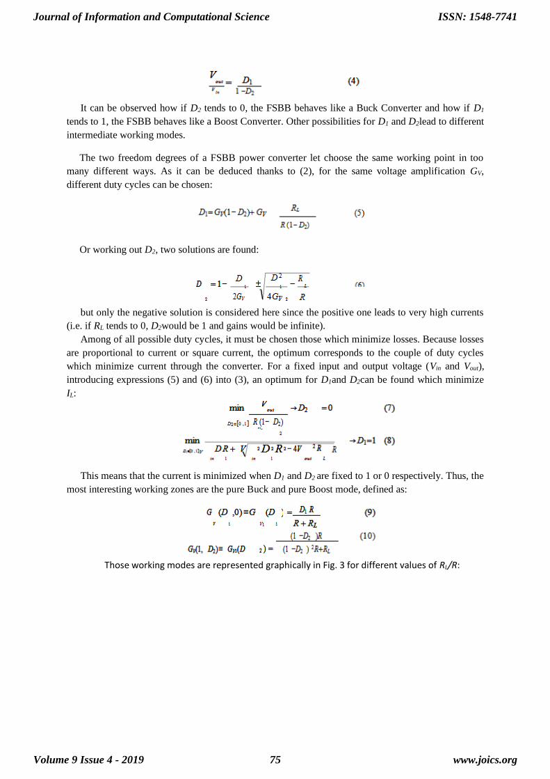
Those working modes are represented graphically in Fig. 3 for different values of RL/R:
Journal of Information and Computational Science
Volume 9 Issue 4 - 2019
ISSN: 1548-7741
www.joics.org75
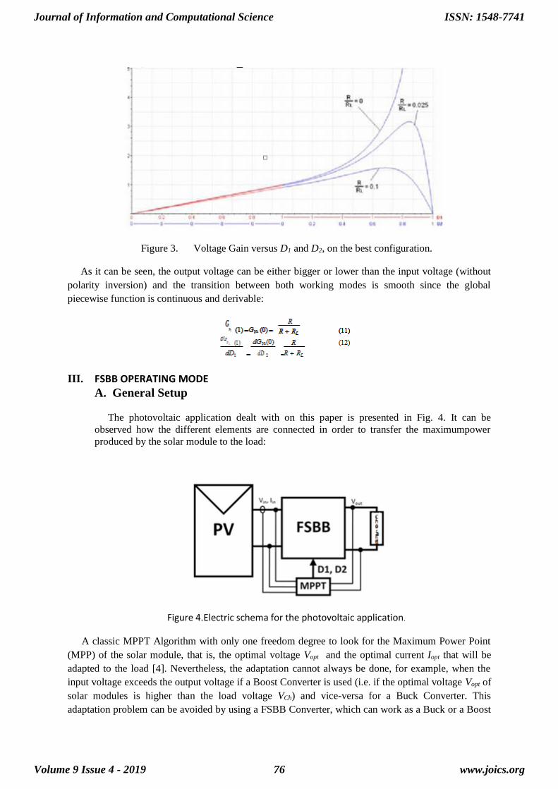
Figure 3. Voltage Gain versus D1 and D2, on the best configuration.
As it can be seen, the output voltage can be either bigger or lower than the input voltage (without
polarity inversion) and the transition between both working modes is smooth since the global
piecewise function is continuous and derivable:
III. FSBB OPERATING MODE
A. General Setup
The photovoltaic application dealt with on this paper is presented in Fig. 4. It can be
observed how the different elements are connected in order to transfer the maximumpower
produced by the solar module to the load:
Figure 4.Electric schema for the photovoltaic application.
A classic MPPT Algorithm with only one freedom degree to look for the Maximum Power Point
(MPP) of the solar module, that is, the optimal voltage Vopt and the optimal current Iopt that will be
adapted to the load [4]. Nevertheless, the adaptation cannot always be done, for example, when the
input voltage exceeds the output voltage if a Boost Converter is used (i.e. if the optimal voltage Vopt of
solar modules is higher than the load voltage VCh) and vice-versa for a Buck Converter. This
adaptation problem can be avoided by using a FSBB Converter, which can work as a Buck or a Boost
Journal of Information and Computational Science
Volume 9 Issue 4 - 2019
ISSN: 1548-7741
www.joics.org76
converter. Furthermore, once the working zones have been fixed, the FSBB becomes a one freedom
degree converter by measuring the input voltage Vin and the output voltage Vout to calculate the voltage
gain GV. Like this, the MPPT Algorithm knows whether to work on Buck or Boost mode.
The system characteristics are: Solar Module that can produce 0V to 20V in function of sunlight
and temperature (BP585: ISC=5A and VOC=22.1V), and a variable resistive load. So, the FSBB must
be able to adapt different output voltages and also to change between the Buck and Boost modes if
needed.
B. FSBB Electric Setup and Control Characteristics
The chosen frequency for all the commutation signals has been fixed to 200 kHz. The FSBB
control is carried on by a DSPIC30F30. Two couples of complementary PWM signals are generated
in function of the MPPT control algorithm.
Attending to the commutation frequency, the elements on the converter have been chosen as
shown in the next table:
TABLE I.CONVERTER ELEMENTS VALUES
L 22uH
RL 0.02Ω
C 20uF
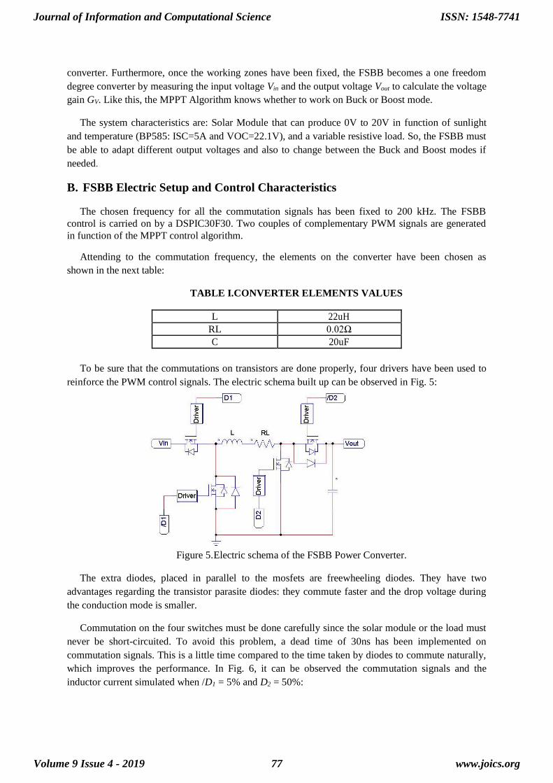
To be sure that the commutations on transistors are done properly, four drivers have been used to
reinforce the PWM control signals. The electric schema built up can be observed in Fig. 5:
Figure 5. Electric schema of the FSBB Power Converter.
The extra diodes, placed in parallel to the mosfets are freewheeling diodes. They have two
advantages regarding the transistor parasite diodes: they commute faster and the drop voltage during
the conduction mode is smaller.
Commutation on the four switches must be done carefully since the solar module or the load must
never be short-circuited. To avoid this problem, a dead time of 30ns has been implemented on
commutation signals. This is a little time compared to the time taken by diodes to commute naturally,
which improves the performance. In Fig. 6, it can be observed the commutation signals and the
inductor current simulated when /D1 = 5% and D2 = 50%:
Journal of Information and Computational Science
Volume 9 Issue 4 - 2019
ISSN: 1548-7741
www.joics.org77
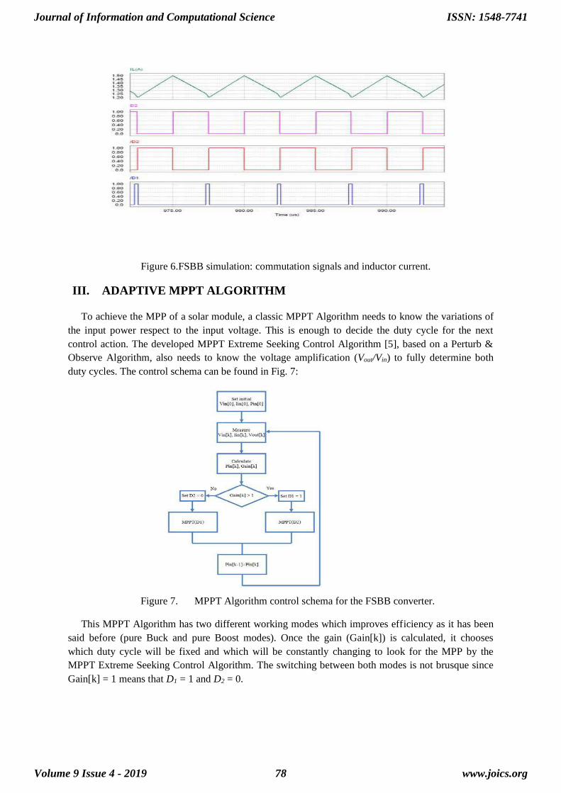
Figure 6.FSBB simulation: commutation signals and inductor current.
III. ADAPTIVE MPPT ALGORITHM
To achieve the MPP of a solar module, a classic MPPT Algorithm needs to know the variations of
the input power respect to the input voltage. This is enough to decide the duty cycle for the next
control action. The developed MPPT Extreme Seeking Control Algorithm [5], based on a Perturb &
Observe Algorithm, also needs to know the voltage amplification (Vout/Vin) to fully determine both
duty cycles. The control schema can be found in Fig. 7:
Figure 7. MPPT Algorithm control schema for the FSBB converter.
This MPPT Algorithm has two different working modes which improves efficiency as it has been
said before (pure Buck and pure Boost modes). Once the gain (Gain[k]) is calculated, it chooses
which duty cycle will be fixed and which will be constantly changing to look for the MPP by the
MPPT Extreme Seeking Control Algorithm. The switching between both modes is not brusque since
Gain[k] = 1 means that D1 = 1 and D2 = 0.
Journal of Information and Computational Science
Volume 9 Issue 4 - 2019
ISSN: 1548-7741
www.joics.org78
IV. EXPERIMENTAL RESULTS
A. FSBB Characteristics
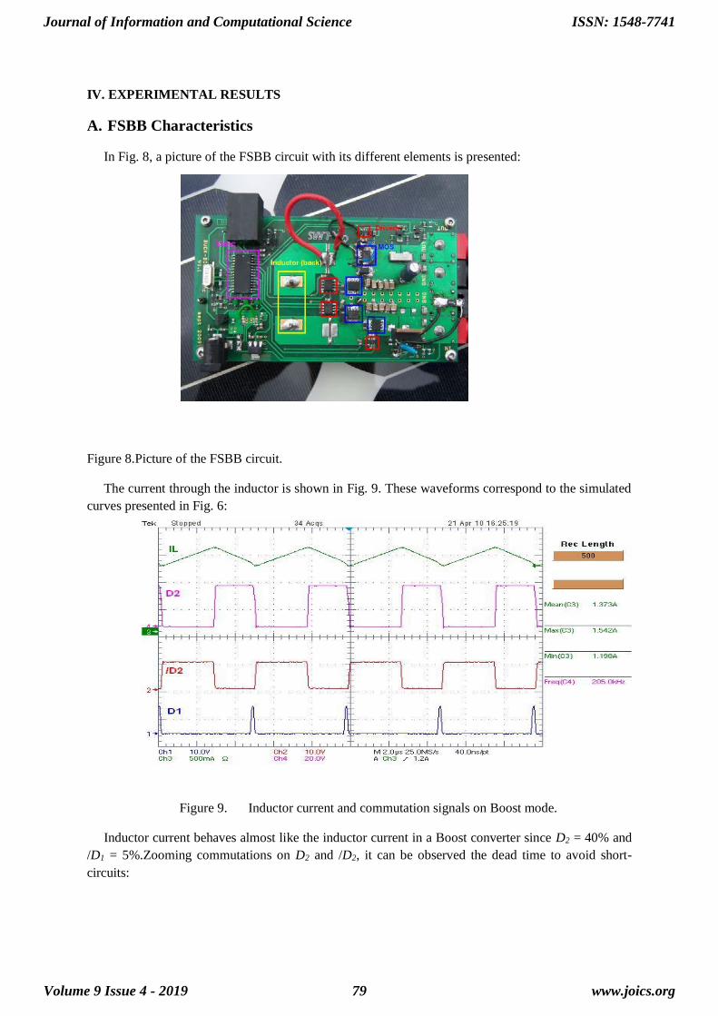
In Fig. 8, a picture of the FSBB circuit with its different elements is presented:
Figure 8.Picture of the FSBB circuit.
The current through the inductor is shown in Fig. 9. These waveforms correspond to the simulated
curves presented in Fig. 6:
Figure 9. Inductor current and commutation signals on Boost mode.
Inductor current behaves almost like the inductor current in a Boost converter since D2 = 40% and
/D1 = 5%.Zooming commutations on D2 and /D2, it can be observed the dead time to avoid short-
circuits:
Journal of Information and Computational Science
Volume 9 Issue 4 - 2019
ISSN: 1548-7741
www.joics.org79
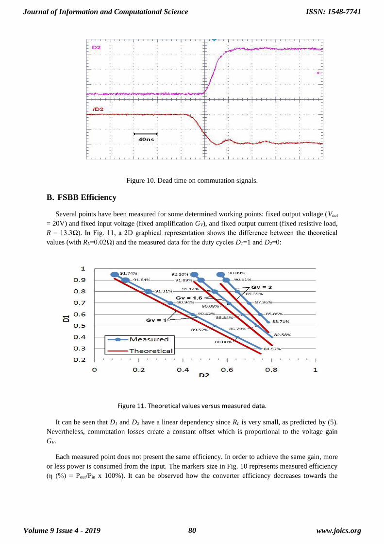
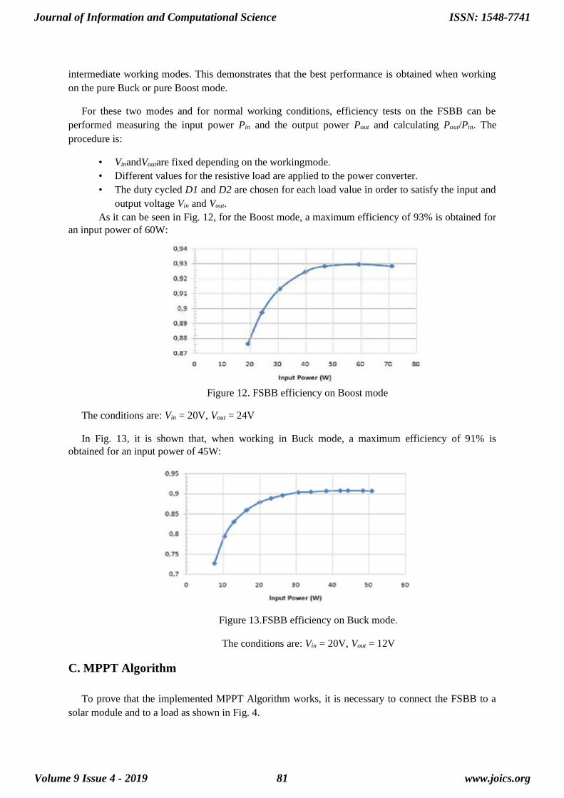
Figure 10. Dead time on commutation signals.
B. FSBB Efficiency
Several points have been measured for some determined working points: fixed output voltage (Vout
= 20V) and fixed input voltage (fixed amplification GV), and fixed output current (fixed resistive load,
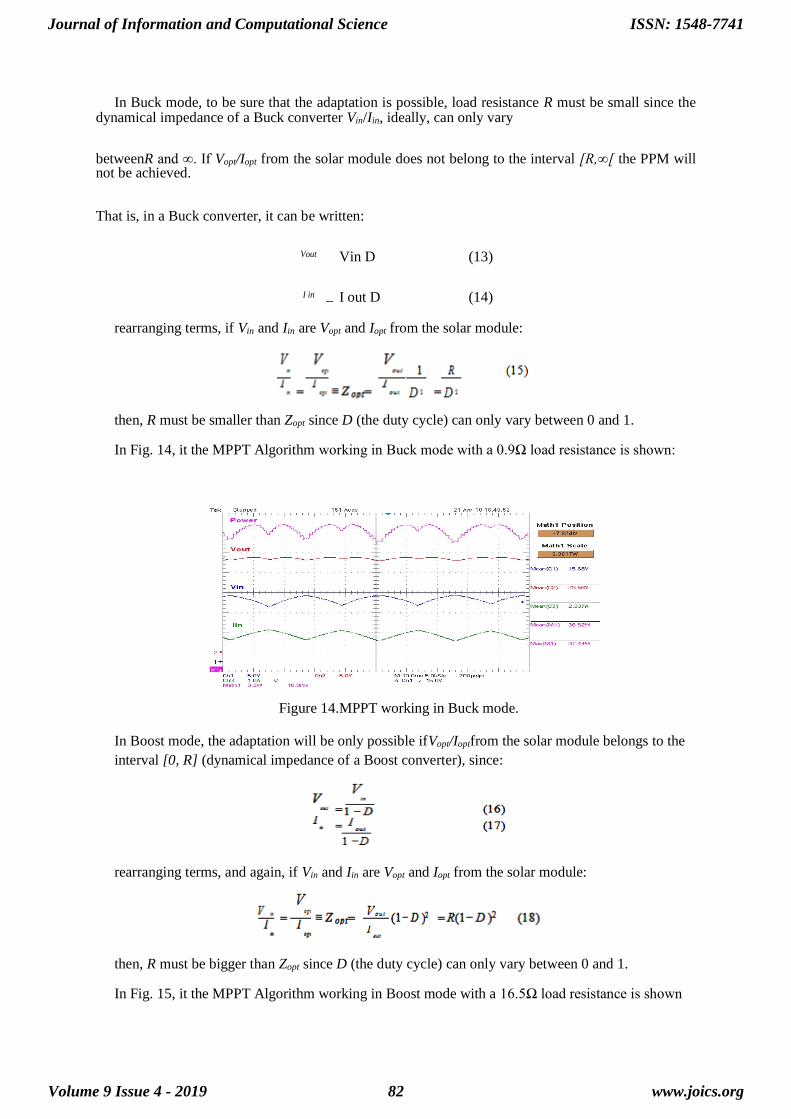
R = 13.3Ω). In Fig. 11, a 2D graphical representation shows the difference between the theoretical
values (with RL=0.02Ω) and the measured data for the duty cycles D1=1 and D2=0:
Figure 11. Theoretical values versus measured data.
It can be seen that D1 and D2 have a linear dependency since RL is very small, as predicted by (5).
Nevertheless, commutation losses create a constant offset which is proportional to the voltage gain
GV.
Each measured point does not present the same efficiency. In order to achieve the same gain, more
or less power is consumed from the input. The markers size in Fig. 10 represents measured efficiency
(η (%) = Pout/Pin x 100%). It can be observed how the converter efficiency decreases towards the
Journal of Information and Computational Science
Volume 9 Issue 4 - 2019
ISSN: 1548-7741
www.joics.org80
intermediate working modes. This demonstrates that the best performance is obtained when working
on the pure Buck or pure Boost mode.
For these two modes and for normal working conditions, efficiency tests on the FSBB can be
performed measuring the input power Pin and the output power Pout and calculating Pout/Pin. The
procedure is:
• VinandVoutare fixed depending on the workingmode.
• Different values for the resistive load are applied to the power converter.
• The duty cycled D1 and D2 are chosen for each load value in order to satisfy the input and
output voltage Vin and Vout.
As it can be seen in Fig. 12, for the Boost mode, a maximum efficiency of 93% is obtained for
an input power of 60W:
Figure 12. FSBB efficiency on Boost mode
The conditions are: Vin = 20V, Vout = 24V
In Fig. 13, it is shown that, when working in Buck mode, a maximum efficiency of 91% is
obtained for an input power of 45W:
Figure 13.FSBB efficiency on Buck mode.
The conditions are: Vin = 20V, Vout = 12V
C. MPPT Algorithm
To prove that the implemented MPPT Algorithm works, it is necessary to connect the FSBB to a
solar module and to a load as shown in Fig. 4.
Journal of Information and Computational Science
Volume 9 Issue 4 - 2019
ISSN: 1548-7741
www.joics.org81
In Buck mode, to be sure that the adaptation is possible, load resistance R must be small since the dynamical impedance of a Buck converter Vin/Iin, ideally, can only vary
betweenR and ∞. If Vopt/Iopt from the solar module does not belong to the interval [R,∞[ the PPM will not be achieved.
That is, in a Buck converter, it can be written:
Vout Vin D (13)
I in I out D (14)
rearranging terms, if Vin and Iin are Vopt and Iopt from the solar module:
then, R must be smaller than Zopt since D (the duty cycle) can only vary between 0 and 1.
In Fig. 14, it the MPPT Algorithm working in Buck mode with a 0.9Ω load resistance is shown:
Figure 14.MPPT working in Buck mode.
In Boost mode, the adaptation will be only possible ifVopt/Ioptfrom the solar module belongs to the
interval [0, R] (dynamical impedance of a Boost converter), since:
rearranging terms, and again, if Vin and Iin are Vopt and Iopt from the solar module:
then, R must be bigger than Zopt since D (the duty cycle) can only vary between 0 and 1.
In Fig. 15, it the MPPT Algorithm working in Boost mode with a 16.5Ω load resistance is shown
Journal of Information and Computational Science
Volume 9 Issue 4 - 2019
ISSN: 1548-7741
www.joics.org82
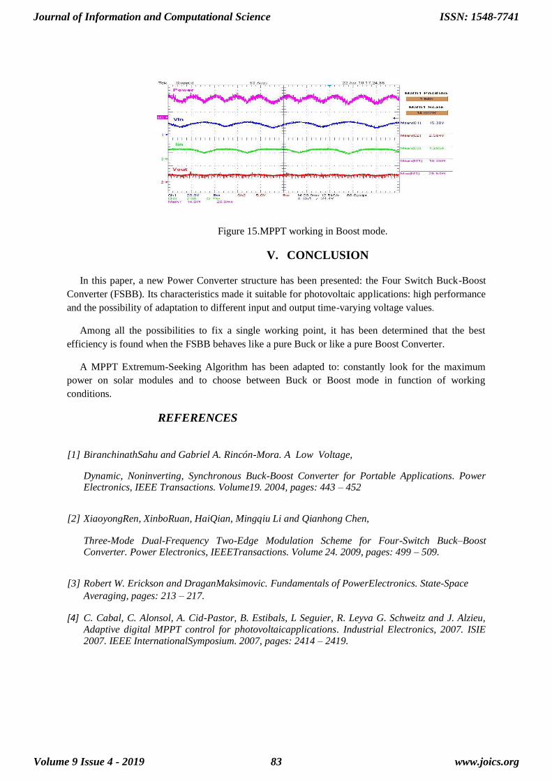
Figure 15.MPPT working in Boost mode.
V. CONCLUSION
In this paper, a new Power Converter structure has been presented: the Four Switch Buck-Boost
Converter (FSBB). Its characteristics made it suitable for photovoltaic applications: high performance
and the possibility of adaptation to different input and output time-varying voltage values.
Among all the possibilities to fix a single working point, it has been determined that the best
efficiency is found when the FSBB behaves like a pure Buck or like a pure Boost Converter.
A MPPT Extremum-Seeking Algorithm has been adapted to: constantly look for the maximum
power on solar modules and to choose between Buck or Boost mode in function of working
conditions.
REFERENCES
[1] BiranchinathSahu and Gabriel A. Rincón-Mora. A Low Voltage,
Dynamic, Noninverting, Synchronous Buck-Boost Converter for Portable Applications. Power Electronics, IEEE Transactions. Volume19. 2004, pages: 443 – 452
[2] XiaoyongRen, XinboRuan, HaiQian, Mingqiu Li and Qianhong Chen,
Three-Mode Dual-Frequency Two-Edge Modulation Scheme for Four-Switch Buck–Boost Converter. Power Electronics, IEEETransactions. Volume 24. 2009, pages: 499 – 509.
[3] Robert W. Erickson and DraganMaksimovic. Fundamentals of PowerElectronics. State-Space
Averaging, pages: 213 – 217.
[4] C. Cabal, C. Alonsol, A. Cid-Pastor, B. Estibals, L Seguier, R. Leyva G. Schweitz and J. Alzieu, Adaptive digital MPPT control for photovoltaicapplications. Industrial Electronics, 2007. ISIE 2007. IEEE InternationalSymposium. 2007, pages: 2414 – 2419.
Journal of Information and Computational Science
Volume 9 Issue 4 - 2019
ISSN: 1548-7741
www.joics.org83