Embed Size (px)
Citation preview
1
Dokumentation für FPS Flexibler Positions - Sensor und Auswerteelektronik FPS-A5 / FPS-F5 / FPS-F5 T
Documentation for FPS flexible position sensor and processor electronics FPS-A5 / FPS-F5 / FPS-F5 T
FPSType:FPS-A5, FPS-F5, FPS-F5 T
FPSType:FPS-A5, FPS-F5, FPS-F5 T
Dru
ck-N
r.:
03 /
FP
S /
DE
-EN
/ 1
5.09
.09
K_1
0.03
.202
1
SCHUNK GmbH & Co. KGSpann- und GreiftechnikBahnhofstr. 106-13474348 Lauffen/NeckarDeutschlandTel. +49-7133-103-0Fax [email protected]
AUSTRIA: SCHUNK Intec GmbHTel. +43-7229-65770-0 · Fax [email protected] · www.at.schunk.com
BELGIUM, LUXEMBOURG:SCHUNK Intec N.V. / S. A.Tel. +32-53-853504 · Fax [email protected] · www.be.schunk.com
CANADA: SCHUNK Intec Corp.Tel. +1-905-712-2200 · Fax [email protected] · www.ca.schunk.com
CHINA: SCHUNK Representative OfficeTel. +86-21-64433177 · Fax [email protected] · www.cn.schunk.com
CZECH REPUBLIC: SCHUNK Intec s.r.o.Tel. +420-545229095 · Fax [email protected] · www.cz.schunk.com
DENMARK: SCHUNK Intec A/STel. +45-43601339 · Fax [email protected] · www.dk.schunk.com
FRANCE: SCHUNK Intec SARLTel. +33-1-64663824 · Fax [email protected] · www.fr.schunk.com
GREAT BRITAIN: SCHUNK Intec Ltd.Tel. +44-1908-611127 · Fax [email protected] · www.gb.schunk.com
RUSSIA: OOO SCHUNK IntecTel. +7-812-326 78 35 · Fax +7-812-326 78 [email protected] · www.ru.schunk.com SLOVAKIA: SCHUNK Intec s.r.o.Tel. +421-37-3260610 · Fax [email protected] · www.sk.schunk.com SOUTH KOREA: SCHUNK Intec Korea Ltd.Tel. +82-31-7376141 · Fax [email protected] · www.kr.schunk.com SPAIN: SCHUNK Intec S.L.Tel. +34-937 556 020 · Fax +34-937 908 [email protected] · www.es.schunk.com SWEDEN: SCHUNK Intec ABTel. +46-8-554-42100 · Fax [email protected] · www.se.schunk.com
SWITZERLAND, LIECHTENSTEIN:SCHUNK Intec AGTel. +41-523543131 · Fax [email protected] · www.ch.schunk.com
TURKEY: SCHUNK IntecTel. +90-2163662111 · Fax [email protected] · www.tr.schunk.com
USA: SCHUNK Intec Inc.Tel. +1-919-572-2705 · Fax [email protected] · www.us.schunk.com
HUNGARY: SCHUNK Intec Kft.Tel. +36-46-50900-7 · Fax [email protected] · www.hu.schunk.com INDIA: SCHUNK India Branch OfficeTel. +91-80-40538999 · Fax [email protected] · www.in.schunk.com ITALY: SCHUNK Intec S.r.l.Tel. +39-031-4951311 · Fax [email protected] · www.it.schunk.com JAPAN: SCHUNK Intec K.K.Tel. +81-33-7743731 · Fax [email protected] · www.tbk-hand.co.jp MEXICO, VENEZUELA:SCHUNK Intec S.A. de C.V.Tel. +52-442-223-6525 · Fax [email protected] · www.mx.schunk.com NETHERLANDS: SCHUNK Intec B.V.Tel. +31-73-6441779 · Fax [email protected] · www.nl.schunk.com POLAND: SCHUNK Intec Sp.z o.o.Tel. +48-22-7262500 · Fax [email protected] · www.pl.schunk.com PORTUGAL: Sales RepresentativeTel. +34-937-556 020 · Fax +34-937-908 [email protected] · www.pt.schunk.com
Reg. No. DE-003496 QM Reg. No. DE-003496 QM
Sehr geehrter Kunde,
wir gratulieren zu Ihrer Entscheidung für SCHUNK. Damit haben Sie sich für höchste Präzision, hervorragende Qualität und besten Service entschieden.
Sie erhöhen die Prozesssicherheit in Ihrer Fertigung und erzielen beste Bearbeitungsergebnisse – für die Zufriedenheit Ihrer Kunden.
SCHUNK-Produkte werden Sie begeistern.Unsere ausführlichen Montage- und Betriebshinweise unterstützen Sie dabei.
Sie haben Fragen? Wir sind auch nach Ihrem Kauf jeder-zeit für Sie da. Sie erreichen uns unter den unten aufge-führten Kontaktadressen.
Mit freundlichen Grüßen
Ihre SCHUNK GmbH & Co. KGSpann- und Greiftechnik
Dear Customer,
Congratulations on choosing a SCHUNK product. By choosing SCHUNK, you have opted for the highest precision, top quality and best service.
You are going to increase the process reliability of your production and achieve best machining results – to the customer‘s complete satisfaction.
SCHUNK products are inspiring.Our detailed assembly and operation manual will support you.
Do you have further questions? You may contact us at any time – even after purchase. You can reach us directly at the below mentioned addresses.
Kindest Regards,
Your SCHUNK GmbH & Co. KGPrecision Workholding Systems
2
Dokumentation für FPS Flexibler Positions - Sensor und Auswerteelektronik FPS-A5 / FPS-F5 / FPS-F5 T
Documentation for FPS flexible position sensor and processor electronics FPS-A5 / FPS-F5 / FPS-F5 T
Inhaltsverzeichnis / Table of contents
Seite / Page
1. Allgemeines / General 31.1 Funktionsprinzip / Operating principles 31.2 Montage des Sensors an den Greifer / Mounting sensors on the gripper 31.3 Anschluss des Sensors und der Auswerteeinheit / Connecting the sensor and electronic processor 31.4 Einsatzhinweise / Instructions for use 31.5 Technische Daten / Technical data 4
2. Hardware und Belegungspläne / Hardware and cable plans 5
3. Die Bedienung des FPS-A5 bzw. FPS-F5 / FPS-F5 T ohne Software /Operating the FPS-A5 / FPS-F5 / FPS-F5 T without software 73.1 Einstellung und Schaltbereiche der zwei Betriebsmodi des FPS (gilt nicht für das FPS-F5 T) /
Set-up and switching ranges for the two FPS operating modes (not FPS-F5 T) 73.2 Einstellen der Positionen »Offen, Zu, A, B und C« / Setting the »open, closed, A, B and C« positions 8
4. Die Bedienung des FPS-F5 / FPS-F5 T mit Software/Fernwartungsfunktionalität /Operating the FPS-F5 / FPS-F5 T with software/remote maintenance functionality 94.1 Allgemeines / General 94.2 Die Initialisierungsdatei / Initialisation file for the FPS controller 9
4.2.1 Die Initialisierungsdatei für den FPS Controller / Initialisation file for the FPS controller 94.2.2 Die Initialisierungsdatei für das Gateway / Gateway initialisation file 9
4.3 Möglichkeiten der Anbindung / Connection options 104.3.1 FPS (zur Inbetriebnahme) am PC / FPS (start up) on a PC 104.3.2 FPS direkt an Leitstand über RS 232 / FPS direct to control system via RS 232 104.3.3 FPS an Modem und Fernwartungs-PC an Modem / FPS to modem and remote PC to modem 104.3.4 FPS an PC im Internet und Fernwartungs-PC am Internet / FPS to PC via internet and remote PC maintenance via internet 11
4.4 Das Programm „FPS-Controller“ / FPS controller software 124.4.1 Login Bildschirm / Login screen 124.4.2 Die Grundanzeigen / Display screen 124.4.3 Die Funktion Programmieren / The programming function 134.4.4 Die Funktion Betriebszustand / The operating status function 144.4.5 Die Funktion Aufnahme / The snapshot function 154.4.6 Die Funktion Kalibrierung / The calibration function 154.4.7 Die Funktion Service / The service function 17
4.5 Lizenzbedingungen / Licence agreement terms and conditions 18
3
Dokumentation für FPS Flexibler Positions - Sensor und Auswerteelektronik FPS-A5 / FPS-F5 / FPS-F5 T
Documentation for FPS flexible position sensor and processor electronics FPS-A5 / FPS-F5 / FPS-F5 T
1. Allgemeines
1.1 Funktionssprinzip
Das Sensorsystem FPS besteht aus einem magnetfeld-empfindlichen Sensor und einer Auswerteeinheit. An der Grundbacke des Greifers ist ein Permanentmagnet angebracht, der parallel am Sensor vorbeifährt. Mit der Stellung des Magneten ändert sich die Ausgangsspannung des Sensors. In der Auswerteeinheit wird diese Spannung verstärkt und in fünf Referenzpunkte aufgeteilt. Die Referenzpunkte werden mit Tastschaltern oder über die Steuerung gespeichert.Beim Erreichen einer eingestellten Position (z.B. entsprechendes Teil gegriffen) wird der zugehörige digitale Ausgang eingeschalten. Die 5 digitalen Ausgänge sind pnp-schaltend und kurzschlussfest. Es ist immer nur ein Ausgang aktiv. Sobald die nächste Position erreicht ist, wird der vorhergehende Ausgang abgeschaltet.
1.2 Montage des Sensors an den Greifer
Der Anbau des Sensors und des Magneten an den Greifer wird in einer separaten Anleitung beschrieben. Diese Anleitung erhalten Sie zusammen mit dem Anbaussatz. Beim Einsetzen des Sensors in den Halter ist zu beachten dass die aktive Fläche des Sensors zum Magneten zeigen muss.
1.3 Anschluss des Sensors und der Auswerteeinheit
Die Verbindung zwischen Sensor und Auswerteeinheit wird mit einem dreipoligen Steckverbinder Größe M4 mit Verschraubung hergestellt. Der Anschluss für die Spannungversorgung, die RS 232 Schnittstelle und die Ausgänge befindet sich auf der dem Sensoranschluss gegenüberliegenden Seite der Auswerteeinheit. Der Stecker ist ein 12-poliger Rundsteckverbinder Type Binder 723 (Kupplungsdose).Die Steckerbelegung ist dem Kapitel Hardware und Belegungspläne zu entnehmen Die Anschlüsse mit den Bezeichnungen »Offen«, »Zu«, »A«, »B« und »C« entsprechen den 5 Schaltausgängen. Der Anschluss »plus« ist an den Pluspol der Versorgungsspannung (12-32 VDC)anzuschließen, der Anschluss »minus« an den Minuspol derVersorgungsspannung (Massepotential). Die Anschlüsse »n.c.«sind nicht belegt.Der Anschluss der Auswerteeinheit erfolgt, indem der Sensor- und Ausgangsstecker aufgesteckt und festgeschraubt werden.Beim Anliegen einer Versorgungsspannung zwischen 10 und32 Volt Gleichspannung, muss eine der Leuchtdioden für dieAusgangssignale leuchten. Ist dies nicht der Fall, so ist entwederdie Polarität der Spannungsversorgung falsch (Verpolungsschutzaktiv!) oder ein Ausgang kurzgeschlossen und der eingebauteKurzschlussschutz hat die Ausgänge abgeschaltet und damitauch die Ausgangsleuchtdioden deaktiviert. In diesem Fall ist derAusgangsstecker zu entfernen und die Ursache des Kurzschlusseszu beseitigen. Oder die Schaltpunkte sind so programmiert, dassder Greifer weiter aufgefahren ist als im Schaltpunkt Auf<-->Ausgespeichert. Um dieses zu testen fahren Sie den Greifer einfachganz zu. Nun muss eine LED leuchten.
1. General
1.1 Operating principles
The FPS sensor system consists of a magnetic field sensitive sensor and an electronic processor. A permanent magnet which moves parallel to the sensor is fitted to the base jaw of a gripper. The magnet‘s position determines the output voltage of the sensor. This voltage is amplified in the electronic processor and divided into five reference points. These reference points are saved using buttons or controls.When a set position is achieved (eg an appropriate component is gripped), the related digital output is switched on. The five digital outputs are pnp switching and short-circuit protected. Only one output is active at any given time. As soon as the next position is reached, the previous output is switched off.
1.2 Mounting the sensor on the gripper
The method of fitting sensors and the magnet to the gripper is described in separate instructions. These instructions are provided with the mounting kit. When locating the sensor in the mount, ensure that the active surface of the sensor is towards the magnet.
1.3 Connecting the sensor and electronic processor
The sensor and electronic processor are connected using a 3 pole plug connection size M 4 attached by means of screws. The connection point for the power supply, the RS 232 interface and outputs are on the opposite side of the electronic processor to the sensor connection point. The plug is a 12 pole circular connector type Binder 723 (coupler socket).See the section on hardware and cable plans for details of connection layout.The connection points marked »open«, »closed«, »A«, »B« and »C« correspond to the five switching outputs. The »plus« connection point must be connected to the plus pole of the power supply (12-32 VDC), the »minus« point to the minus point of the power supply (mass potential). Connections marked „n.c.“ are not used.To connect up the electronic processor, plug the sensor and output connectors together and secure them with screws. If the power supply is between 10 and 32 V direct current, one of the diodes for the output signal must light up. If this does not happen, either the power supply polarity is incorrect (reverse voltage protection active!) or an output has short circuited and the integrated short circuit protection device has switched the outputs off and thus deactivated the output diode. If this is the case, please remove the output connector and rectify the short circuit problem. Alternatively, the switching points might have been programmed in such a way that the gripper has moved beyond the stored shut <-->open switching points. To test this, close the gripper completely. An LED should light up now.
4
Dokumentation für FPS Flexibler Positions - Sensor und Auswerteelektronik FPS-A5 / FPS-F5 / FPS-F5 T
Documentation for FPS flexible position sensor and processor electronics FPS-A5 / FPS-F5 / FPS-F5 T
1.4 Einsatzhinweise
Der Einsatz des Sensors im unmittelbaren Bereich starker Magnetfelder oder die zeitweise Annäherung oder Berührung des Sensors oder des Magneten von größeren ferromagnetischen Materialien ist nicht zu empfehlen. Das Greifen solcher Materialien hat keinen Einfluss, da hier die Abstände zum Sensor ausreichend groß sind (> 10 – 20 mm).Ebenso ist eine Verschmutzung des Sensors oder des Magneten durch ferromagnetische Späne und Stäube zu vermeiden. Um die im Katalog angegebene Genauigkeit zu erreichen, muss die Einstellung des Sensors (Teilepositionen) in betriebswarmem Zustand erfolgen.Der FPS-F5 besitzt an seiner Unterseite einen Erdungsanschluss. Um kleine Störimpulse auf der Masseleitung zu beseitigen sollten Sie den FPS an diesem Anschluss erden. Wird der FPS-F5 auf einer lackierten Metallfläche befestigt, im Bereich des Erdungsanschlusses den Lack entfernen um eine gute Verbindung zu erreichen. Bei größeren Störungen den Verursacher feststellen und beseitigen.
ACHTUNG!FPS-F5 und FPS-F5 T müssen bei einem Einsatz als Messystem bei Inbetriebnahme und in regelmässigen Abständen kalibriert werden.
1.5 Technische Daten
Spannung: 10 – 30 VDC, Restwelligkeit < 15%, ver-polungs geschützt
Stromaufnahme im Leerlauf: typ. 10 mA (eine LED an)
Ausgänge: 5 Schaltausgänge über 2 interne Taster oder über Steuerleitungen frei pro gram-mierbar, für die Positionen »offen«, »ge- schlossen«, 3 Zwischenpositionen, max. 200 mA Schaltstrom pro Ausgang, kurz-schlussfest, Spannungsabfall max. 1.5 V, PNP-schaltend
Anschluss: 12-pol. Rundsteckverbinder (Type BinderSerie 723 wasserdicht) geeignet für An- schlusskabel mit 6 bis 8 mm Ø, emp-fohlener Leitungsquerschnitt 0.14 mm2
(max. 0.25 mm2)
Anzeige: 3 gelbe LED’s für einstellbare Schalt-ausgangsstufen (A, B, C), 2 grüne LED’s für Schaltausgangsstufen (offen, zu)
Temperaturbereich: – 25°C bis + 70°C
Wandler: 12 bit dual slope mit Ausblendung dyna-mischer Signale
Messbereich: 5 bis 30 mm mit SCHUNK-Magnet (NdFeB Magnetzuschnitt Abmessung 6 x 25 mm x L) mit verschiedenen Längen L abhängigvom Teilmessbereich
Wiederholgenauigkeit: ca. 0.5% des Greifer-Gesamthubes, alle Angaben unter Berücksichtigung der SCHUNK Anbauteile und Spezifikationen
Auflösung: besser 10% des Greifer-Gesamthubes meist um 2%, alle Angaben unter Berücksichtigung der SCHUNK Anbauteile und Spezifikationen. Die Auflösung ist der Wert für die Hubdifferenz von Signal 1 zu Signal 2.
1.4 Notes on use
It is not recommended that the sensor be used close to a strong magnetic field or to allow large ferromagnetic materials to come close to or touch the sensor or magnet even for a short while. Gripping such materials does not present a problem as the distance between them and the sensor is sufficiently large (> 10 – 20 mm). It is also recommended that the sensors and magnet not be allowed to become contaminated with ferromagnetic particles and dust.To achieve the accuracy specified in the catalogue, the sensors (workpiece positions) should be set when the system has reached its operating temperature.The FPS-F5 is earthed at the bottom. You should earth the FPS at this point to eliminate small interfering signals on the mass cable. If the FPS-F5 is fixed to a painted metal surface, remove the paint where the earth connection is to be made in order to create a good connection. If there is a large amount of interference, find and remove the source.
CAUTION!If used as a measuring system, FPS-F5 and FPS-F5 T must be calibrated when operated for the first time and at regular intervals.
1.5 Technical Data
Voltage: 10 – 30 VDC residual ripple < 15% polarity protected
Power consumption in unloaded position: type 10 mA (one LED on)
Outputs: 5 switching outputs user-programmable via 2 internal buttons or control cables for positions »open«, »closed«, 3 inter-mediate positions, max. 200 mA switching current per output, short circuit protected, voltage drop max 1.5 V, PNP-switching
Connection: 12 pole circular connector (type Binder, series 723 watertight) suitable for connec-ting cables with a diameter of 6 to 8 mm, recommended cable section 0.14 mm2 (max 0.25 mm2)
Display: 3 yellow LEDs for adjustable output signals (A, B, C), 2 green LEDs for output signals (open, closed)
Temperature range: – 25°C to +70°C
Transducer fade-out: 12 bit dual slope with dynamic signal fade-out
Measuring range: 5 to 30 mm with SCHUNK magnet (NdFeB magnet dimensions 6 x 25 mm x L) with various lengths L depending on partial measuring range
Repetitive accuracy: approximately 0.5 per cent of overall gripper stroke, all data taking into account SCHUNK components and specifications
Resolution: more than 10 per cent of overall gripper stroke, mostly around 2 per cent, all data taking into account SCHUNK components and specifications. The resolution is the value of the difference in stroke between signal 1 and signal 2.
5
Dokumentation für FPS Flexibler Positions - Sensor und Auswerteelektronik FPS-A5 / FPS-F5 / FPS-F5 T
Documentation for FPS flexible position sensor and processor electronics FPS-A5 / FPS-F5 / FPS-F5 T
Das bedeutet z.B. bei einer Auflösung von 10% am Beispiel PGN 160 mit 16 mm Hub eine Differenz von 1.6 mm. Der Wert wird von allen Faktoren des Systems bestimmt (Magnetlänge, Sensor, Abstand zwischen Magnet und Sensor und der Elektronik). Je nach System kann der Wert auch unter 1% liegen. Fragen Sie bei Bedarf nach.
Schutzart: nach DIN 40050: IP 65 mit gesteckter Steckverbindung und geschlossenem Deckel
Material: Kunststoff PA 6, Kabel PU beständig gegen Kühl-/Schmiermittel
Programmier-eingänge: (Auswahl / Speichern) Eingangsspannung
10 – 30 V DC Typ 7 kΩ Eingangswider-stand 1 Million Programmzyklen
Greifer mit FPSAbfrage: Prinzipiell können alle Greifer mit einem
Backenhub bis 30 mm mit dem flexiblen Positionssensor nachgerüstet werden. Viele Greifer sind bereits für den Einsatz des FPS vorbereitet. Informationen hierzu finden Sie bei den Greifern selbst.
Min. Biegeradius(dynamisch): 17.5 mm
Min. Biegeradius(statisch): 35.0 mm
This means, for example, for a resolution of 10 per cent, using the example of PGN 160 with 16 mm stroke, a difference of 1.6 mm. The value is determined by all system factors (magnet lengths, sensors, distance between magnet and sensor and electronics). Depending on the system, this value can be lower than 1 per cent. Please ask, if required.
Protection class: in accordance with DIN 40050: IP 65 with plug-in connectors and closed cover
Material: poly-A PA 6, cable PU, resistant against coolant and lubrication materials
Programmableinputs: (select / save) input voltage 10 – 30 V DC
type 7 kΩ input resistance 1 million pro-gram cycles
Gripper with FPSquery: In principle, all grippers with a jaw
stroke up to 30 mm can be retrofitted with a flexible position sensor. Many grippers are prepped for FPS use. For information on this, please check the gripper in question.
Min. bending radius(dynamic): 17.5 mm
Min. bending radius(static): 35.0 mm
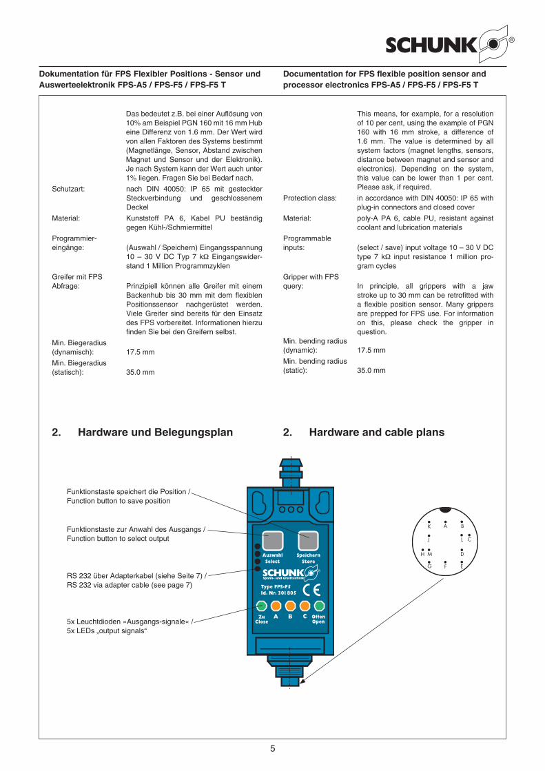
2. Hardware and cable plans2. Hardware und Belegungsplan
K
L
FG E
C
D
A B
M
J
H
5x Leuchtdioden »Ausgangs-signale« /5x LEDs „output signals“
RS 232 über Adapterkabel (siehe Seite 7) /RS 232 via adapter cable (see page 7)
Funktionstaste speichert die Position /Function button to save position
Funktionstaste zur Anwahl des Ausgangs /Function button to select output
6
Dokumentation für FPS Flexibler Positions - Sensor und Auswerteelektronik FPS-A5 / FPS-F5 / FPS-F5 T
Documentation for FPS flexible position sensor and processor electronics FPS-A5 / FPS-F5 / FPS-F5 T
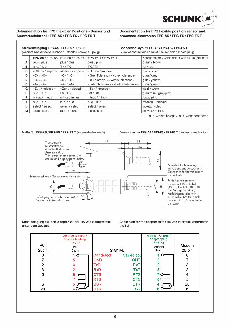
Steckerbelegung FPS-A5 / FPS-F5 / FPS-F5 T (Ansicht Kontaktseite Buchse / Lötseite Stecker 12-polig)
FPS-A5 / FPS-A5 FPS-F5 / FPS-F5 FPS-F5 T / FPS-F5 T Kabelfarbe bei / Cable colour with KV 10 (301 801)A plus / plus plus / plus plus / plus braun / brown
B n. c. / n. c. TX / TX TX / TX rot / redC »Offen« / »open« »Offen« / »open« »Offen« / »open« blau / blue
D »C« / »C« »C« / »C« »über Toleranz« / »over tolerance« grau / greyE »B« / »B« »B« / »B« »in Toleranz« / »within tolerance« gelb / yellowF »A« / »A« »A« / »A« »unter Toleranz« / »below tolerance« grün / greenG »Zu« / »closed« »Zu« / »closed« »Zu« / »closed« weiß / whiteH n. c. / n. c. RX / RX RX / RX grau/rosa / grey/pinkJ minus / minus minus / minus minus / minus rosa / pinkK n. c. / n. c. n. c. / n. c. n. c. / n. c. rot/blau / red/blue
L select / select select / select select / select violett / violetM store / store store / store store / store schwarz / black
Connection layout FPS-A5 / FPS-F5 / FPS-F5 T(View of contact side socket / solder side 12 pole plug)
31
6462
8 56
825
3122
4
Ø 2
2
Sensoranschluss / Sensor connection point
TransparenterKunststoffdeckel, darunter Bedien- undAnzeigenfeld /Transparent plastic cover withcontrol and display panel below
Anschluss für Spannungs-versorgung und Ausgänge /Connection for power supplyand outputs
Befestigung mit 2 Schrauben M4 /Secured with two M4 screws
Fertig konfektionierterStecker mit 10 m Kabel(KV 10, Ident-Nr. 301 801)auf Anfrage lieferbar /Pre-fabricated plug with10 m cable (KV 10, articlenumber 301 801) availableon request
Maße für FPS-A5 / FPS-F5 / FPS-F5 T (Auswerteelektronik) Dimensions for FPS-A5 / FPS-F5 / FPS-F5 T (processor electronics)
n. c. = nicht belegt / n. c. = not connected
Kabelbelegung für den Adapter zu der RS 232 Schnittstelle unter dem Deckel:
Cable plan for the adapter to the RS 232 interface underneath the lid:
7
Dokumentation für FPS Flexibler Positions - Sensor und Auswerteelektronik FPS-A5 / FPS-F5 / FPS-F5 T
Documentation for FPS flexible position sensor and processor electronics FPS-A5 / FPS-F5 / FPS-F5 T
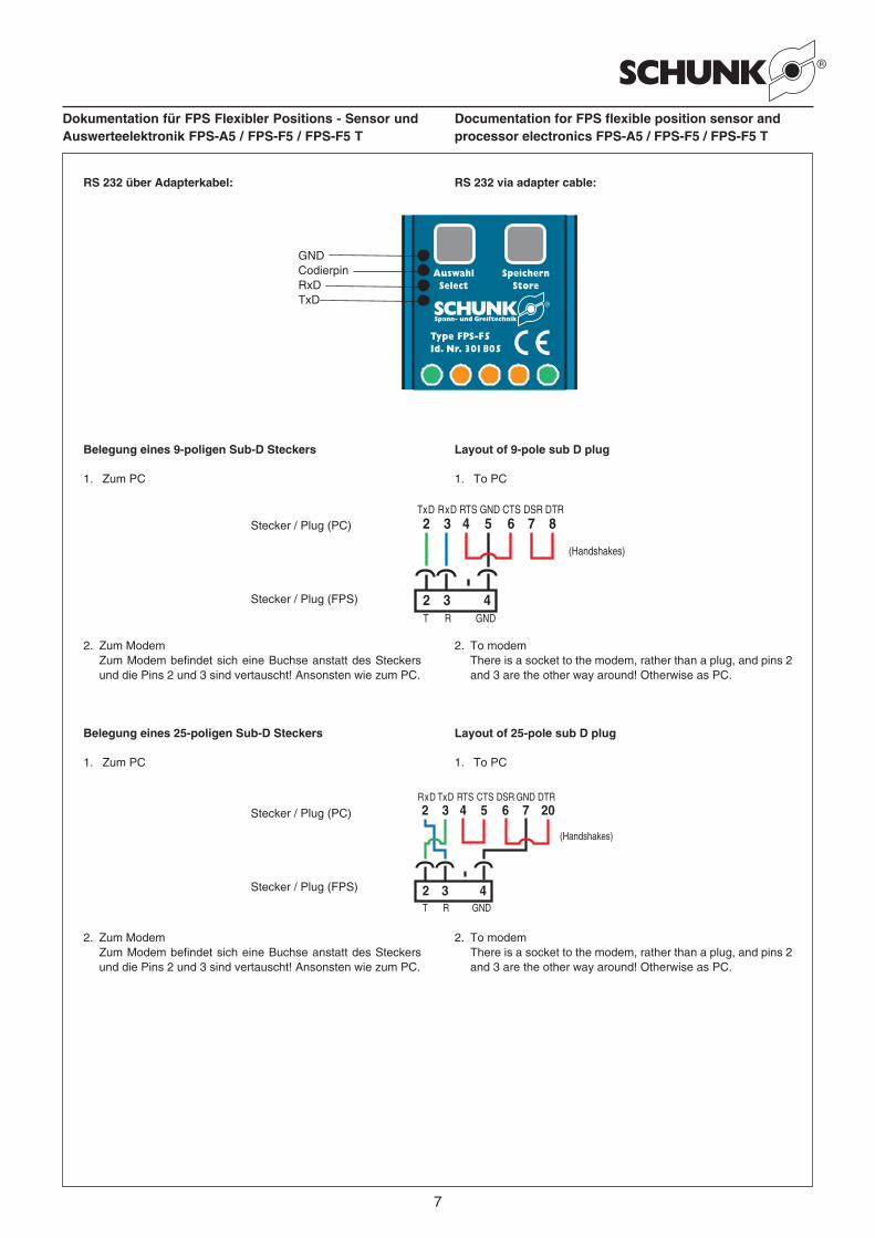
RS 232 über Adapterkabel: RS 232 via adapter cable:
GNDCodierpinRxDTxD
Belegung eines 9-poligen Sub-D Steckers Layout of 9-pole sub D plug
1. Zum PC 1. To PC
2. Zum Modem2. Zum Modem befindet sich eine Buchse anstatt des Steckers
und die Pins 2 und 3 sind vertauscht! Ansonsten wie zum PC.
TxD RxD RTS GND CTS DSR DTR
T R GND
2 3 4
2 3 4 5 6 7 8
(Handshakes)
Stecker / Plug (PC)
Stecker / Plug (FPS)
2. To modem2. There is a socket to the modem, rather than a plug, and pins 2
and 3 are the other way around! Otherwise as PC.
Belegung eines 25-poligen Sub-D Steckers Layout of 25-pole sub D plug
1. Zum PC 1. To PC
2. Zum Modem2. Zum Modem befindet sich eine Buchse anstatt des Steckers
und die Pins 2 und 3 sind vertauscht! Ansonsten wie zum PC.
TxDRxD RTS GNDCTS DSR DTR
T R GND
2 3 4
2 3 4 5 6 7 20
(Handshakes)
Stecker / Plug (PC)
Stecker / Plug (FPS)
2. To modem2. There is a socket to the modem, rather than a plug, and pins 2
and 3 are the other way around! Otherwise as PC.

8
Dokumentation für FPS Flexibler Positions - Sensor und Auswerteelektronik FPS-A5 / FPS-F5 / FPS-F5 T
Documentation for FPS flexible position sensor and processor electronics FPS-A5 / FPS-F5 / FPS-F5 T
3. Die Bedienung des FPS-A5 bzw.FPS-F5 / FPS-F5 T ohne Software
Um die von unserem System FPS-A5 her bekannte Funktionalität zu haben, benötigen Sie weder die RS 232 Schnittstelle noch die Software.
3.1 Einstellung und Schaltbereiche der zwei Betriebsmodi des FPS (gilt nicht für das FPS-F5 T)
Das FPS-A5 und das FPS-F5 haben zwei verschiedene Betriebsmodi:Modus »SICHER« (entspricht in der Software ‚Bereich‘) – Modus »GENAU« (entspricht in der Software ‚Schaltpunkt‘) .Die normale Arbeitsweise, die auch werkseitig eingestellt ist,ist der Modus »SICHER«. Die Arbeitsweise des Betriebsmodus»GENAU« entspricht der ersten FPS-Generation.
Wird die Auswerteeinheit mit dem 12-poligen Rundsteckverbinder (Spannungsversorgung und Ausgänge) zum ersten Mal an die Stromversorgung angeschlossen, schaltet das FPS in den Betriebsmodus »SICHER« – die beiden grünen LED’s für »Zu« und »Offen« blinken 2 Sekunden lang.
Erläuterung der Schaltprinzipien bei den Betriebsmodi »SICHER« und »GENAU«:
Situationsbeispiel:Es ist ein Greifer mit 10 mm Hub eingesetzt.Zu programmieren sind jeweils die Schaltstellungen »ZU«, »Teil A = 4 mm«, »Teil B = 5 mm«, »Teil C = 8 mm«, »OFFEN«.
Schaltpunkte im Modus »SICHER«:Wenn Sie in diesem Betriebsmodus alle 5 Positionen gespeichert haben (siehe Kapitel 3.2), werden die Schaltpunkte auf einen möglichst sicheren Wert, d.h. in die Mitte zwischen den Schalt-punkten gelegt. Programmieren Sie ein oder mehrere Schalt-punkte neu, werden diese mit den unverändert gebliebenen Schalt punkten verrechnet.
Schaltbereiche:
3. Operating the FPS-A5 / FPS-F5 /FPS-F5 T without software
Neither the RS232 interface nor the software is required to have access to the functionality of our FPS A5 system.
3.1 Set-up and switching ranges for the two FPS operating modes (not FP-F5 T)
The FPS-A5 and the FPS-F5 have two different operating modes:»SAFE« mode (equivalent to ‚area‘ mode) and »EXACT« mode(equivalent to ‚switching point‘ mode)The standard working method, which is the factory set up, isthe »SAFE« mode. The working method in »EXACT« modecorresponds to the first generation of FPS units.
When the electronic processor with 12 pole circular connector (power supply and outputs) is connected up to the power supply for the first time, the FPS switches into »SAFE« mode – both green LEDs for »closed« and »open« will flash for two seconds.
Explanation of switching principles in »SAFE« and »EXACT« operating modes:
Example:Gripper with 10 mm stroke.The switching positions to be programmed are »closed«, »workpiece A = 4 mm«, »workpiece B = 5 mm«, »workpiece C= 8 mm«, »OPEN«.
Switching points in »SAFE« mode:Once all five positions have been saved in this operating mode (see section 3.2), the switching points are set to a safe value, ie half way between the switching points. If you reprogram one or more switching points, they are calculated using the unchanged switching points.
Switching ranges:
»Zu« / »closed« »Teil A« / »workpiece A« »Teil B« / »workpiece B« »Teil C« / »workpiece C« »Offen« / »open«unter / less than 2 mm 2,0 – 4,5 mm 4,5 – 6,5 mm 6,5 – 9,0 mm über / greater than 9 mm
Schaltpunkte im Modus »GENAU«:
Schaltbereiche:
Switching points in »EXACT« mode:
Switching ranges:
»Zu« / »closed« »Teil A« / »workpiece A« »Teil B« / »workpiece B« »Teil C« / »workpiece C« »Offen« / »open«unter / less than 0 mm 0 – 4 mm 4 – 5 mm 5 – 8 mm über / greater than 8 mm
Umschalten des BetriebsmodusZum Umschalten von einem Betriebsmodus in den anderen muss die Stromversorgung zum FPS unterbrochen sein! (Ziehen Sie den 12-poligen Steckverbinder von der Auswerteeinheit ab.) Halten Sie die Funktionstaste »Speichern« gedrückt und schließen Sie die Stromversorgung wieder an. Lassen Sie die Taste »Speichern« los – der FPS zeigt durch 2 Sekunden langes Blinken der LED’s den jeweiligen Betriebsmodus an.Im Modus »SICHER« blinken die grünen LED’s »Zu« und »Offen«,im Modus »GENAU« blinken die gelben LED’s »A«, »B« und »C«.
Der eingestellte Betriebsmodus bleibt erhalten.
Changing the operating modeThe FPS power supply must be disconnected before changing from one operating mode to the other! (To do this, remove the 12 pole plug from the electronic processor.) Hold down the »save« function key and reconnect the power supply. Release the »save« button – the FPS will indicate the operating mode by means of LEDs flashing for two seconds.In »SAFE« mode, the green LEDs »closed« and »open« flash,In »EXACT« mode, the yellow LEDs »A«, »B« and »C« flash.
The selected operating mode remains set.
9
Dokumentation für FPS Flexibler Positions - Sensor und Auswerteelektronik FPS-A5 / FPS-F5 / FPS-F5 T
Documentation for FPS flexible position sensor and processor electronics FPS-A5 / FPS-F5 / FPS-F5 T
3.2 Einstellen der Positionen »Offen, Zu, A, B und C« bzw. des Toleranzfelds
Nach der Montage des Sensors und des Magneten am Greifer, müssen die Positionen mit den Tasten am Gerät oder über die Eingänge durch die Steuerung eingespeichert werden.
FPS-A5 und FPS-F5
Speichern der Positionen:
1. Durch Drücken der Taste »Auswahl« oder Aktivieren desEingangssignals »Auswahl«, blinken zuerst 2 Sekunden langdie LED’s des eingestellten Betriebsmodus (siehe Kapitel 3.1).Danach blinkt der zu speichernde Ausgang.
2. Greiferfinger auf die gewünschte Position bringen.
3. Mit der Taste »Speichern« oder aktivieren des Eingangssignals»Speichern« die gewünschte Position abspeichern. Nach derSpeicherung wird automatisch der nächste Ausgang aktiviert.
4. Um alle Positionen zu speichern, wieder mit Punkt 2.weitermachen bis alle Positionen gespeichert sind. Sind allePositionen abgespeichert, blinkt kein Ausgang mehr und dasGerät ist funktionsbereit.
Wenn nur eine bestimmte Position neu gespeichert werden soll, die Taste »Auswahl« oder das Eingangssignal »Auswahl« so oft betätigen, bis der gewünschte Ausgang blinkt. Zum Abspeichern wieder mit Punkt 2. weitermachen.
Beim FPS-F5 kann die Programmierung auch mit dem PC erfolgen.
FPS-F5 T
Beim FPS-F5 T kann über die Tasten des FPS selbst, zwei externen Handschaltern oder eine externe, digitale Steuerung die Nullposition eines Toleranzfeldes verändert werden. Dies ermöglicht einen einfachen Bauteilwechsel mit verschiedenen Toleranz-Nulllagen, jedoch gleichen Toleranzabmaßen. Dies ist jedoch erst NACH der Inbetriebnahme des FPS-F5 T an einem PC und dem Programmieren der Toleranzabmaße möglich.
Die Vorgehensweise zum Ändern der Tolenz-Nulllage ist:
– Greifen des neuen Bauteils– Signal „Select“ von „Low“ auf „High“ und wieder zurück auf
„Low“ legen– Innerhalb von 0,7 Sekunden aber nicht vor 0,01 Sekunden
„Store“ von „Low“ auf „High“ und wieder zurück auf „Low“ legen.Der „High“-Zustand mindestens 0,01 Sekunden anliegen.
Nun ist das obere Toleranzende [Umschaltwert von B nach C = (Neue Nulllage + Toleranz)] und das untere Toleranzende [Umschaltwert von A nach B = (Neue Nulllage – Toleranz)] gespeichert. Ausgang ‚C‘ signalisiert also „Über der Toleranz“, Ausgang ‚A‘ signalisiert „Unter der Toleranz“, und ,B’ signalisiert „Gutteil“.Die Nulllage des Toleranzfeldes kann natürlich auch über den PC programmiert werden, die Toleranzabmaße MÜSSEN jedoch über den PC programmiert werden.
3.2 Setting the »open, closed, A, B and C« positions, and tolerance fields
Once the sensors and magnet have been fitted on the gripper, the positions must be saved using the buttons on the unit or input via the processor.
FPS-A5 and FPS-F5
Saving positions:
1. Press the »selection« button or activate the input signal»selection«, and the LEDs for the selected operating mode willflash for two seconds (see section 3.1). The output to be storedwill flash.
2. Move the gripper fingers to the position required.
3. Using the »save« button or activating the input signal »save«,store the position required. Once this input has been saved,the next output is activated automatically.
4. To save all the positions, carry on with instruction 2 until all thepositions have been stored. Once all the positions have beenstored, no outputs will flash and the unit is ready for use.
If just one position‘s setting needs to be changed, press the »selection« button or activate the »selection« input signal untilthe output required starts to flash. Carry on with instruction 2 tostore the information.
The FPS-F5 can also be programmed using a PC.
FPS-F5 T
The zero position for a tolerance field can be changed on the FPS-F5 T using the buttons on the FPS itself, two external buttons or by means of external digital controls. This makes it easy to replace components which have the same tolerance dimensions but different tolerance zero positions. However this cannot be done until AFTER the FPS-F5 T has been put into operation on a PC and the tolerance dimensions have been programmed in.
The procedure for changing the tolerance zero position is:
– grip the new component– set the „select“ signal from „low“ to „high“ and back to „low“– within 0.7 seconds (but not before 0.1 second“ set „store“ from
„low“ to „high“ and back to „low“ again. The „high“ status mustcontinue for at least 0.01 seconds).
The upper tolerance limit [switching value from B to C – (new zero position + tolerance)] and the lower tolerance limit [switching value from A to B = (new zero position – tolerance)] are now set. Thus, output ‚C‘ indicates „upper tolerance exceeded“, output A indicates „lower tolerance exceeded“, and ‚B‘ indicates „good“.Of course, it is possible to program the tolerance field using the PC. However, the tolerance dimensions MUST be programmed in using the PC.
10
Dokumentation für FPS Flexibler Positions - Sensor und Auswerteelektronik FPS-A5 / FPS-F5 / FPS-F5 T
Documentation for FPS flexible position sensor and processor electronics FPS-A5 / FPS-F5 / FPS-F5 T
4. Die Bedienung des FPS-F5/ FPS-F5 T mit Software /Fernwartungsfunktionalität
4.1 Allgemeines
Die Software für das FPS besteht aus zwei Programmen:
1. Das Gateway
Sobald das Gateway gestartet ist überwacht es den in der INI-Datei gewählten seriellen Port (Com – Port) und ankommende Anfragen aus dem Internet. Die vom FPS-F5 kommenden Signale an dem COM-Port werden vom Gateway in das TCP/IP – Protokoll umgesetzt und stehen somit dem Netzwerk, an welchem der PC angeschlossen ist, zur Verfügung. Kommt eine Anfrage aus dem Internet prüft das Gateway (wenn in der INI-Datei gewählt) das Passwort ab und gibt die Verbindung zum FPS frei. Hierzu wird der Port 5000 – 5002 verwendet. Sind alle anderen Ports für Zugriffe gesperrt, so ist der PC damit gegen unerwünschte Zugriffe aus dem Netzwerk geschützt.
2. Der FPS-Controler
Der FPS Controller visualisiert das angeschlossene FPS-F5 bzw. Das FPS-F5 T. Es baut auf der mitgelieferten DLL auf. Alle Befehle können also auch direkt in eine andere Software eingebunden werden.Hierbei ist es egal ob die Verbindung direkt über den COM-Port, das Internet oder ein Modem erfolgt. Wichtig ist lediglich, dass vorab das Gateway gestartet wurde.
Die Software für das FPS-F5 und das FPS-F5 T sind gleich. Der Unterschied der beiden Geräte liegt nur in der Firmware. Die Bedienung der Geräte unterscheidet sich jedoch. Die Unterschiede sind im Punkt Kalibrierung und Programmierung ersichtlich.Achtung: Die Software "FPS Controller" ist nur mit Windows 7 oder älteren Versionen kompatibel.
4.2 Die Initialisierungsdatei
4.2.1 Die Initialisierungsdatei für den FPS Controller
In der Initialisierungsdatei befinden sich verschiedene Infor-mationen, welche den Programmstart beeinflussen. Die Datei wird beim Programmstart einmal gelesen. Die meisten Einträge werden während der Programmlaufzeit geschrieben, um Ihnen bei einem Neustart die für Sie optimalen Einstellungen sofort zur Verfügung zu stellen.Alle voreingestellten Einträge treffen für fast jedes System zu.Bei Problemen nehmen Sie bitte Kontakt mit der Fa. SCHUNK auf.
4.2.2 Die Initialisierungsdatei für das Gateway
In der Initialisierungsdatei befinden sich verschiedene Informationen, welche den Programmstart beeinflussen. Die Datei wird beim Programmstart einmal gelesen. Die meisten Einträge werden während der Programmlaufzeit geschrieben, um Ihnen bei einem Neustart die für Sie optimalen Einstellungen sofort zur Verfügung zu stellen.Bei Problemen nehmen Sie bitte Kontakt mit der Fa. SCHUNK auf.
4. Operating the FPS-F5 /FPS-F5 T with software /remote maintenance functionality
4.1 General
The FPS software comprises two programs:
1. Gateway
As soon as Gateway has been launched it monitors the serial port (com port) specified in the INI file and incoming queries from the internet. Signals coming into the COM-port from FPS-F5 are converted by Gateway into a TCP/IP protocol and are thus available for use by the network to which the PC is connected.When a query comes in from the internet, Gateway checks the password (if specified in the INI file) and permits connection to FPS. Port 5000 – 5002 is used for this purpose. If all other ports are blocked for access, the PC is thus protected against unwanted access from the network.
2. FPS controller
The FPS controller visualises the FPS-F5 / FPS-F5T which is connected. It uses the DLL supplied. This means that all commands can also be linked into other software.It does not make any difference whether the connection occurs directly via the COM port, the internet or a modem. What is important, however, is that Gateway is started up first.
The software is the same for the FPS-F5 and FPS-F5 T. The difference between the two devices lies in the firmware only. Operation is not the same for both, however. It differs in how they are calibrated and programmed.Attention: The software "FPS Controller" is only compatible with Windows 7 or older versions.
4.2 Initialisation file
4.2.1 Initialisation file for the FPS controller
The initialisation file contains all sorts of information which can affect the program start up. The file is read once when the program is launched. Most of the inputs are written during program run time to give you the optimum settings immediately when restarting.All the default settings are valid for most systems.If you have any problems, please contact SCHUNK.
4.2.2 Gateway initialisation file
The initialisation file contains all sorts of information which can affect the program start up. The file is read once when the program is launched. Most of the inputs are written during program run time to give you the optimum settings immediately when restarting.If you have any problems, please contact SCHUNK.
11
Dokumentation für FPS Flexibler Positions - Sensor und Auswerteelektronik FPS-A5 / FPS-F5 / FPS-F5 T
Documentation for FPS flexible position sensor and processor electronics FPS-A5 / FPS-F5 / FPS-F5 T
Die wichtigsten Einträge :
– Ports hier wird eingegeben, wieviele FPS gleichzeitig angeschlossen werden
– Secured = 0 keine Passwortabfrage
– Secured = 1 Passwortabfrage bei Programmstart. Sinnvoll,wenn das FPS über einen PC am Internet hängt.
– Password Hier steht das Passwort, welches der User beim Anmelden an das FPS eingeben muss, wenn er versucht auf das FPS zuzugreifen (siehe auch Startbildschirm)
– [Port1] Hier werden die Einstellungen gemacht, welche für das erste FPS zutreffen, hier müssen Sie eventuell Ihren COM-Port eintragen, COM1 ist voreingestellt.
– [Port2] Falls ein zweites FPS gleichzeitig angeschlossen ist, werden hier die Einstellungen gemacht, welche für das zweite FPS zutreffen, hier müssen Sie eventuell Ihren COM-Port eintragen, COM2 ist voreingestellt.
4.3 Möglichkeiten der Anbindung
4.3.1 FPS (zur Inbetriebnahme) am PC
Zu Inbetriebnahme, Kontrolle vor Ort oder Parametierung des FPS, binden Sie das Gerät am einfachsten direkt an Ihren Lap-Top an. Verwenden Sie hierzu das mitgelieferte Adapterkabel: Öffnen Sie den Deckel vom FPS mittels eines kleines Schraubendrehers, stecken Sie das Kabel vorsichtig in die 3 Buchsen unter dem Deckel ein und schließen Sie den Deckel zur Fixierung des Flachbandkabels wieder. Stecken Sie nun die Buchse des Adapters in die serielle Schnittstelle Ihres PC’s ein. Sie können ein serielles Kabel als Verlängerung dazwischenstecken. Legen Sie an das FPS Spannung an.Geben Sie in der TCPIP_RS232_GW.ini Ihren COM-Port ein, speichern Sie die Datei.Starten Sie das Gateway.Starten Sie den FPS Controller.Klicken Sie Netzwerk an und geben Sie als IP-Adresse die Adresse 127.0.0.1 ein und bestätigen Sie die Eingaben mit O.K.Nach wenigen Sekunden sollten Sie nun das Controller Fenster im Online-Zustand vor sich sehen.
4.3.2 FPS direkt an Leitstand über RS 232
Schließen Sie das FPS mittels des mitgeliefertem Steckers und eines Kabels an Spannung und an eine serielle Schnittstelle Ihres Leitstandes oder einer untergeordneten Steuerung an. Auf der Steuerung muß ein Windows System installiert sein. Bei Bedarf kann auch ein Linux System von uns (gegen Aufpreis) supportet werden.Installieren Sie die auf der Compact Disc mitgelieferte API auf Ihrem Rechner.Binden Sie die benötigten Befehle entsprechend den in der Dokumentation beschriebenen Beispielen in IHRE Software ein.
4.3.3 FPS an Modem und Fernwartungs-PC an Modem
Legen Sie an das FPS Spannung an.Starten Sie Hyperterminal (Hypertrm.exe), geben Sie als Name FPS ein und bestätigen Sie mit OK, wählen Sie verbinden über ‚Direktverbindung über Com1‘ und drücken Sie OK, Stellen Sie folgende Parameter ein:
Most important settings:
– Ports enter how many FPS will be connected up simultaneously
– Secured = 0 no password confirmation
– Secured = 1 password required on program start-up. Shouldbe used if the PFC is connected to a PC via the internet.
– Password this is the password which must be entered by the user when logging on to the FPS and trying to access the FPS (see also start up screen)
– [Port1] this is for settings for the first FPS. COM1 is the default, you might have to put in a different COM port.
– [Port2] this is for settings for the second FPS, if it is connected up simultaneously. COM2 is the default, you might have to put in a different COM port.
4.3 Connection options
4.3.1 FPS (start up) on a PC
The simplest option for starting up and checking FPS parameters on site, is to connect the device directly to your lap top.To do this, use the adapter cable supplied: open the FPS lid using a small screwdriver, carefully insert the cable into the three plug points under the lid and close it to secure the cable in place. Now insert the adapter into the serial interface on your PC. You can connect a serial cable in the middle as an extension lead.Connect the FPS power supply.Enter your COM port in the TCPIP_RS232_GW.ini file and save the file.Start the Gateway.Start the FPS controller.Click on network and enter 127.0.0.1 for the IP address. Confirm the input with OK.After a few seconds, the controller window should be displayed on screen with a status of on line.
4.3.2 FPS direct to control system via RS 232
Connect the FPS to the power supply using the plug supplied and a cable to a serial interface on your control station or to a secondary control device. The control device must have a Windows system installed. If required, we can support a Linux system for an additional charge.Install the API on your system from the CD supplied.Link the required commands into YOUR software as per the examples described in the documentation.
4.3.3 FPS to modem and remote PC to modem
Connect the FPS power supply.Start up the hyper terminal (Hypertrm.exe), enter FPS as the name and confirm with OK. Select ‚direct connection via Com1“ and press OK, then set the following parameters:
12
Dokumentation für FPS Flexibler Positions - Sensor und Auswerteelektronik FPS-A5 / FPS-F5 / FPS-F5 T
Documentation for FPS flexible position sensor and processor electronics FPS-A5 / FPS-F5 / FPS-F5 T
– Bits pro Sekunde: 9600– Datenbits: 8– Parität: keine– Stopbits: 1– Protokoll: kein– Drücken Sie OK
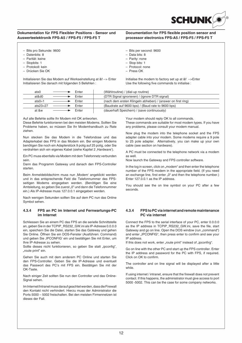
Initialisieren Sie das Modem auf Werkseinstellung at &f --> EnterInitialisieren Sie danach mit folgenden 5 Befehlen :
Auf alle Befehle sollte Ihr Modem mit OK antworten.Diese Befehle funktionieren bei den meisten Modems. Sollten Sie Probleme haben, so müssen Sie Ihr Modemhandbuch zu Rate ziehen.
Nun stecken Sie das Modem in die Telefondose und das Adapterkabel des FPS in das Modem ein. Bei einigen Modems benötigen Sie noch ein Adapterstück 9 polig auf 25 polig, oder Sie verdrahten sich ein eigenes Kabel (siehe Kapitel 2 ‚Hardware‘).
Ein PC muss ebenfalls via Modem mit dem Telefonnetz verbunden sein.Dann das Programm Gateway und danach den FPS-Controller starten.
Beim Anmeldebildschirm muss nun ‚Modem‘ angeklickt werden und in das entsprechende Feld die Telefonnummer des FPS-seitigen Modems eingegeben werden. (Benötigen Sie eine Amtsleitung, so geben Sie zuerst „0” und dann die Telefonnummer ein.) Als IP-Adresse muss 127.0.0.1 eingegeben werden.
Nach wenigen Sekunden sollten Sie auf dem PC nun das Online Symbol sehen.
4.3.4 FPS an PC im Internet und Fernwartungs-PC im Internet
Schliessen Sie an einem PC das FPS an die serielle Schnittstelle an, geben Sie in der TCPIP_RS232_GW.ini als IP-Adresse 0.0.0.0 ein, speichern Sie die Datei, starten Sie das Gateway und gehen Sie Online. Öffnen Sie ein DOS-Fenster (Ausführen: Command) und geben Sie ‚IPCONFIG‘ ein und bestätigen Sie mit Enter, um Ihre IP-Adresse zu sehen.Sollte dieses nicht funktionieren, so geben Sie statt „ipconfig”, „route print” ein.
Gehen Sie auch mit dem anderem PC Online und starten Sie den FPS-Controller. Geben Sie die IP-Adresse und eventuell das Passwort des PC’s mit FPS ein. Bestätigen Sie mit der OK-Taste.
Nach einiger Zeit sollten Sie nun den Controller und das Online-Signal sehen.
Im Internet/Intranet muss darauf geachtet werden, dass die Firewall den Kontakt nicht verhindert. Hierzu muss der Administrator die Ports 5000 – 5002 freischalten. Bei den meisten Firmennetzen ist dieses der Fall.
atx0 Enter (Wählroutine) / (dial-up routine)at&d0 Enter (DTR Signal ignorieren) / (ignore DTR signal)ats0=1 Enter (nach dem ersten Klingeln abheben) / (answer on first ring)ats23=27 Enter (Baudrate auf 9600 bps) / (Baud rate to 9600 bps)at &w Enter (dauerhaft Speichern) / (save continuously)
– Bits per second: 9600– Data bits: 8– Parity: none– Stop bits: 1– Protocol: none– Press OK
Initialise the modem to factory set up at &f -->EnterUse the following five commands to initialise :
Your modem should reply OK to all commands.These commands are suitable for most modem types. If you have any problems, please consult your modem manual.
Now plug the modem into the telephone socket and the FPS adapter cable into your modem. Some modems require a 9 pole to 25 pole adapter. Alternatively, you can make up your own cable (see section on hardware).
A PC must be connected to the telephone network via a modem as well.Now launch the Gateway and FPS controller software.
In the log in screen, click on „modem“ and then enter the telephone number of the FPS modem in the appropriate field. (If you need an exchange line, first enter „0“ and then the telephone number.) Enter 127.0.0.1 as the IP address.
You should see the on line symbol on your PC after a few seconds.
4.3.4 FPS to PC via internet and remote maintenance PC via internet
Connect the FPS to the serial interface of your PC, enter 0.0.0.0 as the IP address in TCPIP_RS232_GW.ini, save the file, start Gateway and go on line. Open the DOS window (run „command“) and enter „IPCONFIG“, then press enter to confirm and see your IP address.If this does not work, enter „route print“ instead of „ipconfirg“.
Go on line with the other PC and start up the FPS controller. Enter the IP address and password for the PC with FPS, if required. Click on OK to confirm.
The controller and on line signal will be displayed after a little while.
If using internet / intranet, ensure that the firewall does not prevent contact. If this happens, the administrator must give access to port 5000 -5002. This can be the case for some company networks.
13
Dokumentation für FPS Flexibler Positions - Sensor und Auswerteelektronik FPS-A5 / FPS-F5 / FPS-F5 T
Documentation for FPS flexible position sensor and processor electronics FPS-A5 / FPS-F5 / FPS-F5 T
4.4 Das Programm „FPS-Controller“
4.4.1 Login Bildschirm
Der Login Bildschirm öffnet sich bei Programmstart automatisch.Mit Hilfe des Login können sich die Benutzer des Programms identifizieren. Wenn in der INI-Datei die Variable password=yes gesetzt ist wird das in der INI-Datei eingetragene Passwort abgefragt.
Es kann gewählt werden, wie das FPS angeschlossen ist:– Modem und Telefonnummer– Internet mit Internetadresse des Rechners, an welchem das
Gateway gestartet wurde, und das FPS-F5 angeschlossen ist,sowie die Portnummer des FPS-F5 (siehe hierzu auch dieINI-Datei).
– Direkter Anschluss an den Com-Port des Rechners selbst =Netzwerk und IP-Adresse 127.0.0.1
4.4.2 Die Grundanzeigen
Alle Bildschirme haben denselben Grundaufbau.
Die Menüleiste zum Beenden und zum Aufrufen der Hilfe.
Die Funktionsleiste zum Wählen der Funktion der unteren Bildschirmhälfte.
Die Statusleiste zum Anzeigen vom Verbindungsstatus, der Art der Verbindung und der gewählten Einheit.
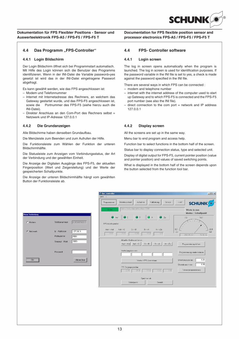
Die Anzeige der Digitalen Ausgänge des FPS-F5, der aktuellen Fingerposition (Wert und Zeigerstellung) und der Werte der gespeicherten Schaltpunkte.
Die Anzeige der unteren Bildschirmhälfte hängt vom gewählten Button der Funktionsleiste ab.
4.4 FPS- Controller software
4.4.1 Login screen
The log in screen opens automatically when the program is launched. The log in screen is used for identification purposes. If the password variable in the INI file is set to yes, a check is made against the password specified in the INI file.
There are several ways in which FPS can be connected :– modem and telephone number– internet with the internet address of the computer used to start
up Gateway and to which FPS-F5 is connected and the FPS-F5port number (see also the INI file).
– direct connection to the com port = network and IP address127.0.0.1
4.4.2 Display screen
All the screens are set up in the same way.
Menu bar to end program and access help.
Function bar to select functions in the bottom half of the screen.
Status bar to display connection status, type and selected unit.
Display of digital output for FPS-F5, current pointer position (value and pointer position) and values of saved switching points.
What is displayed in the bottom half of the screen depends upon the button selected from the function tool bar.
14
Dokumentation für FPS Flexibler Positions - Sensor und Auswerteelektronik FPS-A5 / FPS-F5 / FPS-F5 T
Documentation for FPS flexible position sensor and processor electronics FPS-A5 / FPS-F5 / FPS-F5 T
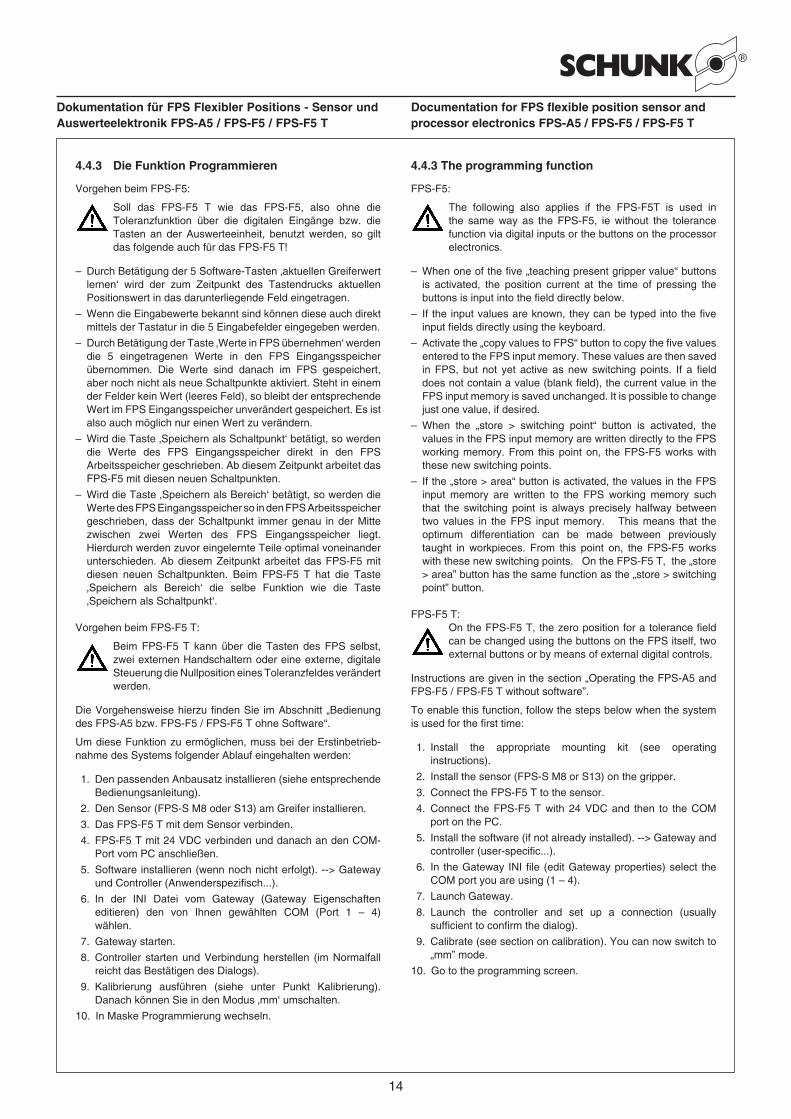
4.4.3 Die Funktion Programmieren
Vorgehen beim FPS-F5:
Soll das FPS-F5 T wie das FPS-F5, also ohne die Toleranzfunktion über die digitalen Eingänge bzw. die Tasten an der Auswerteeinheit, benutzt werden, so gilt das folgende auch für das FPS-F5 T!
– Durch Betätigung der 5 Software-Tasten ‚aktuellen Greiferwertlernen‘ wird der zum Zeitpunkt des Tastendrucks aktuellenPositionswert in das darunterliegende Feld eingetragen.
– Wenn die Eingabewerte bekannt sind können diese auch direktmittels der Tastatur in die 5 Eingabefelder eingegeben werden.
– Durch Betätigung der Taste ‚Werte in FPS übernehmen‘ werdendie 5 eingetragenen Werte in den FPS Eingangsspeicherübernommen. Die Werte sind danach im FPS gespeichert,aber noch nicht als neue Schaltpunkte aktiviert. Steht in einemder Felder kein Wert (leeres Feld), so bleibt der entsprechendeWert im FPS Eingangsspeicher unverändert gespeichert. Es istalso auch möglich nur einen Wert zu verändern.
– Wird die Taste ‚Speichern als Schaltpunkt‘ betätigt, so werdendie Werte des FPS Eingangsspeicher direkt in den FPSArbeitsspeicher geschrieben. Ab diesem Zeitpunkt arbeitet dasFPS-F5 mit diesen neuen Schaltpunkten.
– Wird die Taste ‚Speichern als Bereich‘ betätigt, so werden dieWerte des FPS Eingangsspeicher so in den FPS Arbeitsspeichergeschrieben, dass der Schaltpunkt immer genau in der Mittezwischen zwei Werten des FPS Eingangsspeicher liegt.Hierdurch werden zuvor eingelernte Teile optimal voneinanderunterschieden. Ab diesem Zeitpunkt arbeitet das FPS-F5 mitdiesen neuen Schaltpunkten. Beim FPS-F5 T hat die Taste‚Speichern als Bereich‘ die selbe Funktion wie die Taste‚Speichern als Schaltpunkt‘.
Vorgehen beim FPS-F5 T:
Beim FPS-F5 T kann über die Tasten des FPS selbst, zwei externen Handschaltern oder eine externe, digitale Steuerung die Nullposition eines Toleranzfeldes verändert werden.
Die Vorgehensweise hierzu finden Sie im Abschnitt „Bedienung des FPS-A5 bzw. FPS-F5 / FPS-F5 T ohne Software“.
Um diese Funktion zu ermöglichen, muss bei der Erstinbetrieb-nahme des Systems folgender Ablauf eingehalten werden:
1. Den passenden Anbausatz installieren (siehe entsprechendeBedienungsanleitung).
2. Den Sensor (FPS-S M8 oder S13) am Greifer installieren.
3. Das FPS-F5 T mit dem Sensor verbinden.
4. FPS-F5 T mit 24 VDC verbinden und danach an den COM-Port vom PC anschließen.
5. Software installieren (wenn noch nicht erfolgt). --> Gatewayund Controller (Anwenderspezifisch...).
6. In der INI Datei vom Gateway (Gateway Eigenschafteneditieren) den von Ihnen gewählten COM (Port 1 – 4)wählen.
7. Gateway starten.
8. Controller starten und Verbindung herstellen (im Normalfallreicht das Bestätigen des Dialogs).
9. Kalibrierung ausführen (siehe unter Punkt Kalibrierung).Danach können Sie in den Modus ‚mm‘ umschalten.
10. In Maske Programmierung wechseln.
4.4.3 The programming function
FPS-F5:
The following also applies if the FPS-F5T is used in the same way as the FPS-F5, ie without the tolerance function via digital inputs or the buttons on the processor electronics.
– When one of the five „teaching present gripper value“ buttonsis activated, the position current at the time of pressing thebuttons is input into the field directly below.
– If the input values are known, they can be typed into the fiveinput fields directly using the keyboard.
– Activate the „copy values to FPS“ button to copy the five valuesentered to the FPS input memory. These values are then savedin FPS, but not yet active as new switching points. If a fielddoes not contain a value (blank field), the current value in theFPS input memory is saved unchanged. It is possible to changejust one value, if desired.
– When the „store > switching point“ button is activated, thevalues in the FPS input memory are written directly to the FPSworking memory. From this point on, the FPS-F5 works withthese new switching points.
– If the „store > area“ button is activated, the values in the FPSinput memory are written to the FPS working memory suchthat the switching point is always precisely halfway betweentwo values in the FPS input memory. This means that theoptimum differentiation can be made between previouslytaught in workpieces. From this point on, the FPS-F5 workswith these new switching points. On the FPS-F5 T, the „store> area” button has the same function as the „store > switchingpoint” button.
FPS-F5 T:On the FPS-F5 T, the zero position for a tolerance field can be changed using the buttons on the FPS itself, two external buttons or by means of external digital controls.
Instructions are given in the section „Operating the FPS-A5 and FPS-F5 / FPS-F5 T without software”.
To enable this function, follow the steps below when the system is used for the first time:
1. Install the appropriate mounting kit (see operatinginstructions).
2. Install the sensor (FPS-S M8 or S13) on the gripper.
3. Connect the FPS-F5 T to the sensor.
4. Connect the FPS-F5 T with 24 VDC and then to the COMport on the PC.
5. Install the software (if not already installed). --> Gateway andcontroller (user-specific...).
6. In the Gateway INI file (edit Gateway properties) select theCOM port you are using (1 – 4).
7. Launch Gateway.
8. Launch the controller and set up a connection (usuallysufficient to confirm the dialog).
9. Calibrate (see section on calibration). You can now switch to„mm” mode.
10. Go to the programming screen.
15
Dokumentation für FPS Flexibler Positions - Sensor und Auswerteelektronik FPS-A5 / FPS-F5 / FPS-F5 T
Documentation for FPS flexible position sensor and processor electronics FPS-A5 / FPS-F5 / FPS-F5 T
Folgende Punkte werden automatisch beim Ende der Kalibrierung vorgenommen:(Diese Punkte müssen Sie nur ausführen, wenn Sie nicht kalibriert haben)
– Greifer auf fahren und Wert lernen als Aus<-->Auf und alsAuf<-->C.
– Greifer ganz zu fahren und Wert lernen als A<-->Zu.
– Wir empfehlen den Wert Aus<-->Auf nun um 0,5 mm zuerhöhen, den Wert Auf<-->C um 0,5 mm zu verringern undden Wert A<-->Zu um 0,5 mm zu erhöhen. Sollten Sie diesen0,5 mm Hub nicht in der Anwendung benötigen, erreichen Siehierdurch ein wesentlich stabileres System.
– Taste ‚Werte in FPS übernehmen’ drücken.
– Wenn übernommen: Taste ‚Schaltpunkt‘ drücken.
Diese 2 Punkte MÜSSEN Sie ausführen, um mit dem System zu arbeiten:
– Im Feld Toleranz Ihren gewünschten Toleranzwert eingeben.
– Teil mit Nennmaß greifen und Taste „Toleranzprogrammierung“drücken.
Nun benötigen Sie den PC nur noch wenn Sie die Toleranzabmaße ändern wollen. Die normale Bedienung erfolgt nun einfach digital über die 2 Eingänge (siehe oben).
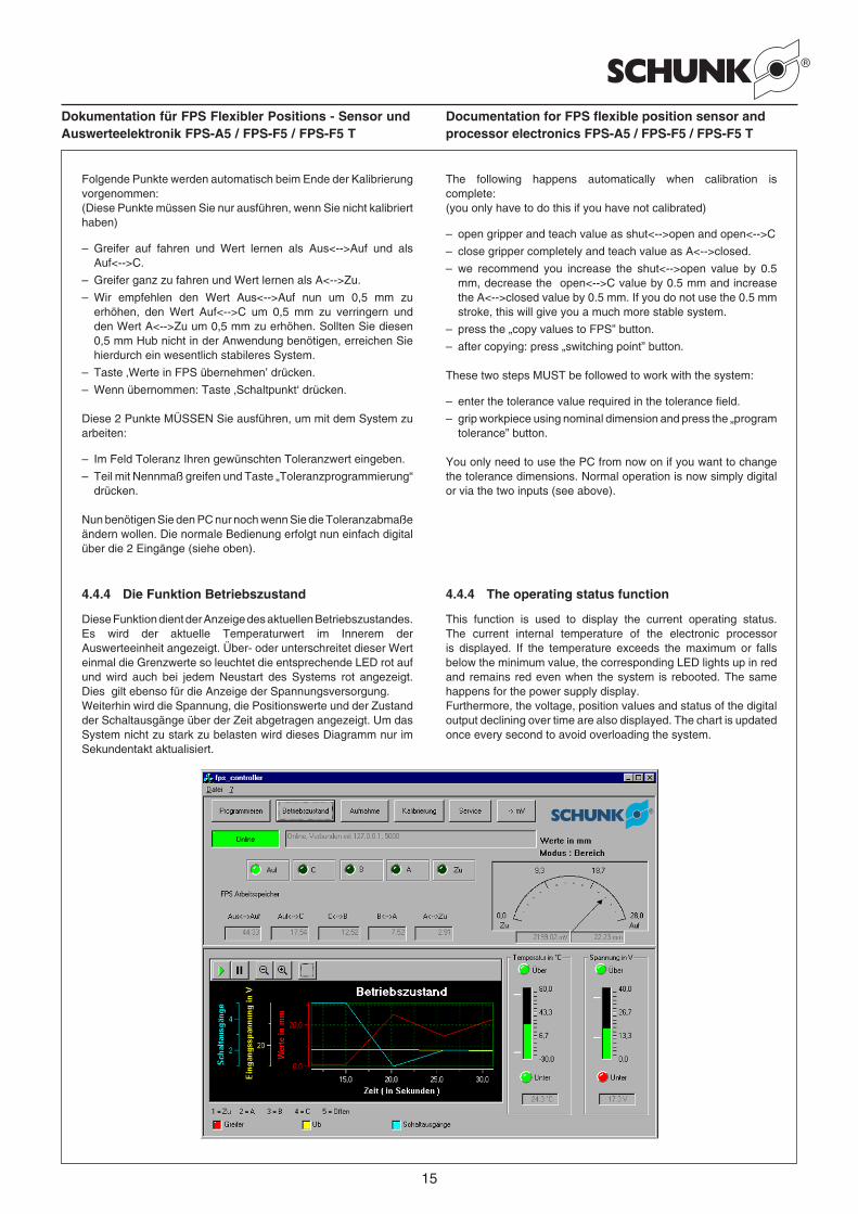
4.4.4 Die Funktion Betriebszustand
Diese Funktion dient der Anzeige des aktuellen Betriebszustandes. Es wird der aktuelle Temperaturwert im Innerem der Auswerteeinheit angezeigt. Über- oder unterschreitet dieser Wert einmal die Grenzwerte so leuchtet die entsprechende LED rot auf und wird auch bei jedem Neustart des Systems rot angezeigt. Dies gilt ebenso für die Anzeige der Spannungsversorgung.Weiterhin wird die Spannung, die Positionswerte und der Zustand der Schaltausgänge über der Zeit abgetragen angezeigt. Um das System nicht zu stark zu belasten wird dieses Diagramm nur im Sekundentakt aktualisiert.
The following happens automatically when calibration is complete:(you only have to do this if you have not calibrated)
– open gripper and teach value as shut<-->open and open<-->C
– close gripper completely and teach value as A<-->closed.
– we recommend you increase the shut<-->open value by 0.5mm, decrease the open<-->C value by 0.5 mm and increasethe A<-->closed value by 0.5 mm. If you do not use the 0.5 mmstroke, this will give you a much more stable system.
– press the „copy values to FPS” button.
– after copying: press „switching point” button.
These two steps MUST be followed to work with the system:
– enter the tolerance value required in the tolerance field.
– grip workpiece using nominal dimension and press the „programtolerance” button.
You only need to use the PC from now on if you want to change the tolerance dimensions. Normal operation is now simply digital or via the two inputs (see above).
4.4.4 The operating status function
This function is used to display the current operating status. The current internal temperature of the electronic processor is displayed. If the temperature exceeds the maximum or falls below the minimum value, the corresponding LED lights up in red and remains red even when the system is rebooted. The same happens for the power supply display.Furthermore, the voltage, position values and status of the digital output declining over time are also displayed. The chart is updated once every second to avoid overloading the system.
16
Dokumentation für FPS Flexibler Positions - Sensor und Auswerteelektronik FPS-A5 / FPS-F5 / FPS-F5 T
Documentation for FPS flexible position sensor and processor electronics FPS-A5 / FPS-F5 / FPS-F5 T
Werden detalierter Informationen benötigt, so empfiehlt sich die Funktion Aufnahme. Durch Betätigung der Lupen kann in dem Diagramm gezoomt werden. Nach Betätigung der Fenster-Taste kann ein beliebiger Bereich des Fensters gezoomt werden.
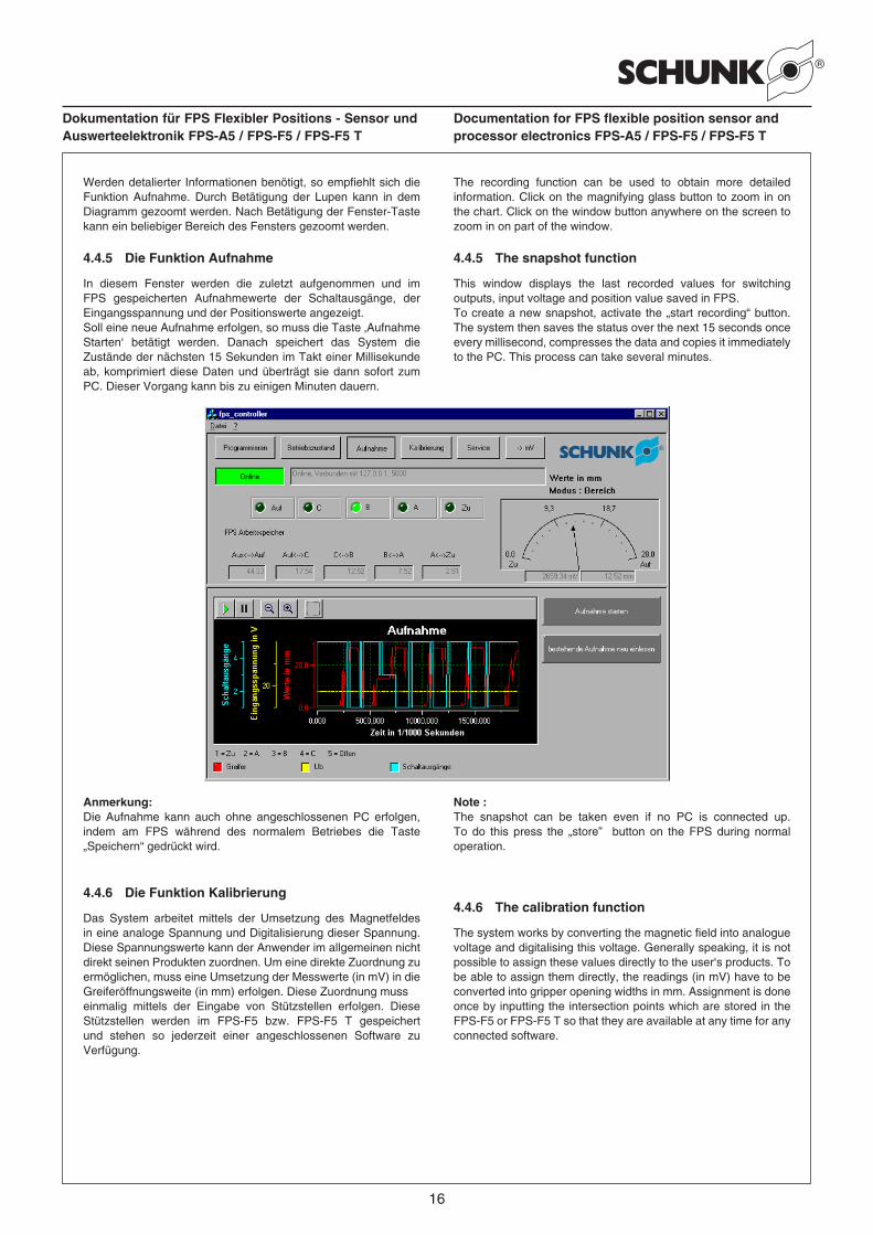
4.4.5 Die Funktion Aufnahme
In diesem Fenster werden die zuletzt aufgenommen und im FPS gespeicherten Aufnahmewerte der Schaltausgänge, der Eingangsspannung und der Positionswerte angezeigt. Soll eine neue Aufnahme erfolgen, so muss die Taste ‚Aufnahme Starten‘ betätigt werden. Danach speichert das System die Zustände der nächsten 15 Sekunden im Takt einer Millisekunde ab, komprimiert diese Daten und überträgt sie dann sofort zum PC. Dieser Vorgang kann bis zu einigen Minuten dauern.
Anmerkung: Die Aufnahme kann auch ohne angeschlossenen PC erfolgen, indem am FPS während des normalem Betriebes die Taste „Speichern“ gedrückt wird.
4.4.6 Die Funktion Kalibrierung
Das System arbeitet mittels der Umsetzung des Magnetfeldes in eine analoge Spannung und Digitalisierung dieser Spannung. Diese Spannungswerte kann der Anwender im allgemeinen nicht direkt seinen Produkten zuordnen. Um eine direkte Zuordnung zu ermöglichen, muss eine Umsetzung der Messwerte (in mV) in die Greiferöffnungsweite (in mm) erfolgen. Diese Zuordnung muss einmalig mittels der Eingabe von Stützstellen erfolgen. Diese Stützstellen werden im FPS-F5 bzw. FPS-F5 T gespeichert und stehen so jederzeit einer angeschlossenen Software zu Verfügung.
The recording function can be used to obtain more detailed information. Click on the magnifying glass button to zoom in on the chart. Click on the window button anywhere on the screen to zoom in on part of the window.
4.4.5 The snapshot function
This window displays the last recorded values for switching outputs, input voltage and position value saved in FPS.To create a new snapshot, activate the „start recording“ button. The system then saves the status over the next 15 seconds once every millisecond, compresses the data and copies it immediately to the PC. This process can take several minutes.
Note :The snapshot can be taken even if no PC is connected up. To do this press the „store” button on the FPS during normal operation.
4.4.6 The calibration function
The system works by converting the magnetic field into analogue voltage and digitalising this voltage. Generally speaking, it is not possible to assign these values directly to the user‘s products. To be able to assign them directly, the readings (in mV) have to be converted into gripper opening widths in mm. Assignment is done once by inputting the intersection points which are stored in the FPS-F5 or FPS-F5 T so that they are available at any time for any connected software.
17
Dokumentation für FPS Flexibler Positions - Sensor und Auswerteelektronik FPS-A5 / FPS-F5 / FPS-F5 T
Documentation for FPS flexible position sensor and processor electronics FPS-A5 / FPS-F5 / FPS-F5 T
Da das Magnetfeld nicht linear ist, ändert sich das Verhältnis Delta(mV) zu Delta(mm) an jeder Hubstellung des Greifers. Deswegen kann erst nach der Kalibrierung mit absoluten Toleranzen gearbeitet werden. Das Arbeiten mit Toleranzen in mV birgt eine große Fehlerquelle und funktioniert nur in einem sehr begrenzten Bereich (Quasilinearer Bereich der Magnetfeldkurve).
Wir empfehlen deswegen möglichst erst nach der Kalibrierung und dann nur im Modus mm mit dem FPS-F5 T zu arbeiten.
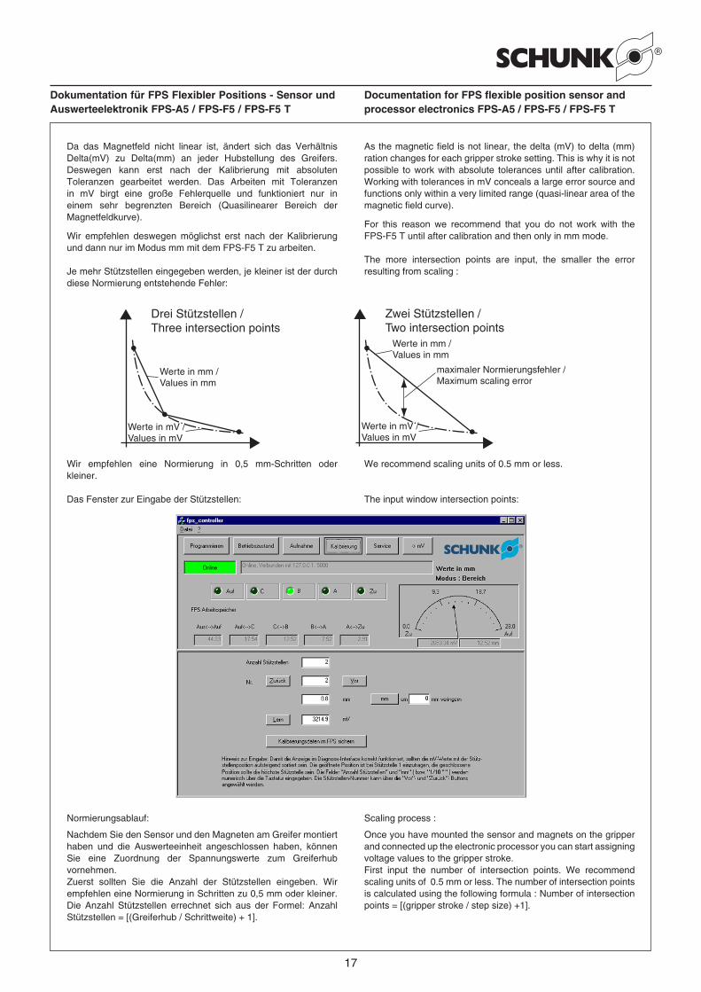
Je mehr Stützstellen eingegeben werden, je kleiner ist der durch diese Normierung entstehende Fehler:
As the magnetic field is not linear, the delta (mV) to delta (mm) ration changes for each gripper stroke setting. This is why it is not possible to work with absolute tolerances until after calibration. Working with tolerances in mV conceals a large error source and functions only within a very limited range (quasi-linear area of the magnetic field curve).
For this reason we recommend that you do not work with the FPS-F5 T until after calibration and then only in mm mode.
The more intersection points are input, the smaller the error resulting from scaling :
maximaler Normierungsfehler /Maximum scaling error
Werte in mV /Values in mV
Werte in mm /Values in mm
Zwei Stützstellen /Two intersection points
Drei Stützstellen /Three intersection points
Werte in mm /Values in mm
Werte in mV /Values in mV
Wir empfehlen eine Normierung in 0,5 mm-Schritten oder kleiner.
Das Fenster zur Eingabe der Stützstellen:
We recommend scaling units of 0.5 mm or less.
The input window intersection points:
Normierungsablauf:
Nachdem Sie den Sensor und den Magneten am Greifer montiert haben und die Auswerteeinheit angeschlossen haben, können Sie eine Zuordnung der Spannungswerte zum Greiferhub vornehmen.Zuerst sollten Sie die Anzahl der Stützstellen eingeben. Wir empfehlen eine Normierung in Schritten zu 0,5 mm oder kleiner. Die Anzahl Stützstellen errechnet sich aus der Formel: Anzahl Stützstellen = [(Greiferhub / Schrittweite) + 1].
Scaling process :
Once you have mounted the sensor and magnets on the gripper and connected up the electronic processor you can start assigning voltage values to the gripper stroke.First input the number of intersection points. We recommend scaling units of 0.5 mm or less. The number of intersection points is calculated using the following formula : Number of intersection points = [(gripper stroke / step size) +1].
18
Dokumentation für FPS Flexibler Positions - Sensor und Auswerteelektronik FPS-A5 / FPS-F5 / FPS-F5 T
Documentation for FPS flexible position sensor and processor electronics FPS-A5 / FPS-F5 / FPS-F5 T
Mit der Eingabe fangen Sie bei der Position ‚Greifer ganz geöffnet‘ an. Dieses entspricht nun der Stützstelle 1. Fahren Sie den Greifer ganz auf, danach geben Sie die Öffnungsweite in mm ein, und drücken dann die Taste ‚Lern‘.Um den nächsten Schritt einzulernen, betätigen Sie die Taste ‚Vor‘, bringen den Greifer in die nächste Position (in Richtung geschlossen), geben die neue Öffnungsweite ein und betätigen wiederum die Taste ‚Lern‘.
Sie können alternativ auch immer den mm-Wert um eine Schrittweite verringern und gleichzeitig zur nächsten Stützstelle springen indem Sie die Taste ‚Schritt‘ betätigen. (Hierbei wird allerdings ein eventuell schon vorhandener Wert auf der entsprechenden Stützstelle überschrieben.) Danach den Greifer um eine Schrittweite schließen und die Taste ,Lern’ betätigen.
Nachdem Sie alle Stützstellen von ‚Greifer Auf‘ bis ‚Greifer Zu‘ eingelernt haben müssen Sie nur noch die Taste ‚Kalibrierungsdaten im FPS sichern‘ betätigen. Damit wird beim FPS-F5 T gleichzeitig auch die Programmierung der Schaltpunkte Aus <--> Auf, Auf <--> C und A <--> Zu vorgenommen, um fehlerhafte Zustände zu vermeiden.Mit den Tasten ‚Zurück‘ und ‚Vor‘ können Sie jederzeit, ohne eine Änderung vorzunehmen, die eingegebenen Stützstellen überprüfen.
Die Stützstellen müssen in der Reihenfolge von „geöffnet“ nach „geschlossen“ einprogrammiert werden und damit sortiert vorliegen!
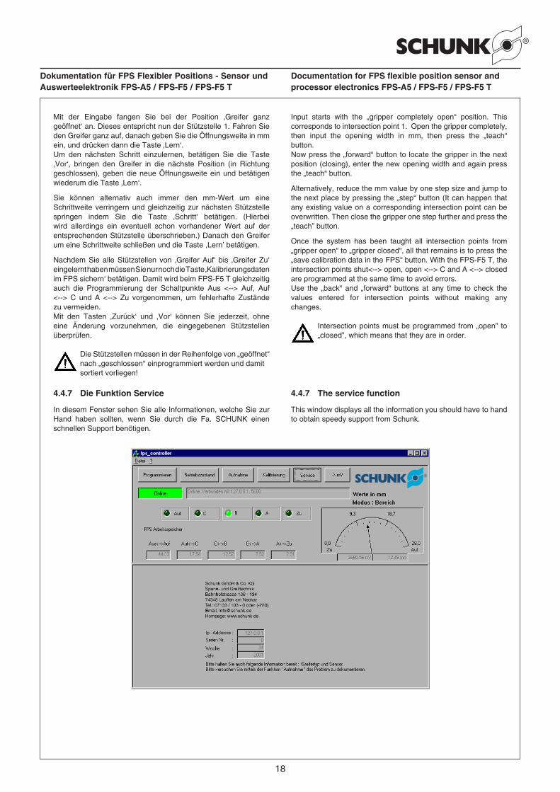
4.4.7 Die Funktion Service
In diesem Fenster sehen Sie alle Informationen, welche Sie zur Hand haben sollten, wenn Sie durch die Fa. SCHUNK einen schnellen Support benötigen.
Input starts with the „gripper completely open“ position. This corresponds to intersection point 1. Open the gripper completely, then input the opening width in mm, then press the „teach“ button.Now press the „forward“ button to locate the gripper in the next position (closing), enter the new opening width and again press the „teach“ button.
Alternatively, reduce the mm value by one step size and jump to the next place by pressing the „step“ button (It can happen that any existing value on a corresponding intersection point can be overwritten. Then close the gripper one step further and press the „teach” button.
Once the system has been taught all intersection points from „gripper open“ to „gripper closed“, all that remains is to press the „save calibration data in the FPS“ button. With the FPS-F5 T, the intersection points shut<--> open, open <--> C and A <--> closed are programmed at the same time to avoid errors.Use the „back“ and „forward“ buttons at any time to check the values entered for intersection points without making any changes.
Intersection points must be programmed from „open” to „closed”, which means that they are in order.
4.4.7 The service function
This window displays all the information you should have to hand to obtain speedy support from Schunk.
19
Dokumentation für FPS Flexibler Positions - Sensor und Auswerteelektronik FPS-A5 / FPS-F5 / FPS-F5 T
Documentation for FPS flexible position sensor and processor electronics FPS-A5 / FPS-F5 / FPS-F5 T
4.5 Lizenzbedingungen
für die Verwendung der FPS-F5 Software,der SCHUNK GmbH & Co. KG, Bahnhofstraße 106-134, 74348 Lauffen/Neckar
1. Gegenstand des Vertrages1. Gegenstand des Vertrages sind die auf dem Datenträger
(Diskette oder CD-Rom) aufgezeichneten Computerprogramme,die Programmbeschreibung und die Bedienungsanleitungsowie eventuell dazugehörendes schriftliches Material (imfolgenden Software).
1. Dem Verwender ist bekannt, dass es nach dem Stand derTechnik nicht möglich ist, Computersoftware so zu erstellen,dass sie in allen Anwendungen und Kombinationen fehlerfreiarbeitet. Gegenstand des Vertrages ist daher nur eineSoftware, die im Sinne der Programmbeschreibung und derBenutzungsanleitung grundsätzlich brauchbar ist.
2. Umfang der Benutzung1. Durch Ingebrauchnahme der Datenträger erkennt der Verwender
diese Lizenzbedingungen an und erwirbt das unwiderrufliche,jedoch nicht übertragbare und nicht ausschließliche Recht, dieSoftware für eigene – persönliche oder betriebliche – Zweckeim Einsatz auf einem Computersystem zu benutzen. Ist derVerwender mit den Lizenzbedingungen nicht einverstanden,so hat er die Datenträger gegen Erstattung seiner Portokostenunverzüglich zurückzugeben.
1. Kopien der Software dürfen ausschließlich nur zu Sicherungs- und Archivierungszwecken angefertigt werden.
1. Eine weitergehende Nutzung ist nicht zulässig.
3. Besondere Beschränkungen1. Dem Verwender ist es insbesondere untersagt, ohne
vorherige schriftliche Einwilligung von SCHUNK die Softwarean einen Dritten zu übergeben oder einem Dritten zugänglichzu machen. Des weiteren ist es ausdrücklich nicht gestattet,ohne vorherige schriftliche Einwilligung von SCHUNK dieSoftware abzuändern, zu übersetzen, zurückzuentwickeln, zuentkompilieren oder zu disassemblieren.
4. Inhaberschaft an Rechten1. Der Verwender erhält mit der Übergabe des Datenträgers
lediglich Eigentum an dem Datenträger. Ein über dasNutzungsrecht hinausgehender Erwerb von Rechten an derSoftware selbst ist damit nicht verbunden.
1. SCHUNK behält sich insbesondere alle Veröffentlichungs-,Vervielfältigungs-, Bearbeitungs- und Verwertungsrechte ander Software vor.
1. Die Software und das Schriftmaterial sind urheberrechtlichgeschützt.
1. An den Datenträgern oder in der Software vorhandeneUrheberrechtsvermerke sind unverändert zu belassen.
5. Übertragung des Benutzungsrechts1. Das Recht zur Benutzung der Software kann nur mit
vorheriger, schriftlicher Einwilligung von SCHUNK und nurunter Weitergabe dieser Lizenzbedingungen an einen Drittenübertragen werden.
1. Verschenken, Vermietung, Verleih oder sonstige Weitergabeder Software an Dritte ist ausdrücklich untersagt.
1. Die Geltendmachung eines Schadens bleibt vorbehalten.
4.5 Licensing terms for the FPS-F5 software
for using of the FPS-F5 software,from SCHUNK GmbH & Co. KG, Bahnhofstraße 106-134, 74348 Lauffen/Neckar
1. Subject of the contract1. The subject of this contract is the computer software stored on
data media (disk or CD-ROM), the description of the programand operating instructions and any associated written material(hereinafter called software).
1. The user is aware that although the programs are developedin keeping with the latest technological advances, faultlessfunctionality in all applications and combinations cannot beguaranteed. The subject of this contract is therefore solely thesoftware which can be used in principle in the sense of theprogram description and operation instructions.
2. Scope of use1. By using the data medium the user recognises these terms
and conditions and acquires the irrevocable, but non-transferable and non-exclusive right to use the software for hisown – personal or work – purposes – running on a computersystem. If the user does not agree to the terms and conditionsof this licence agreement, he shall return the data mediumimmediately. Postage costs shall be reimbursed.
1. Copies of the software may be made for back up and archivepurposes only.
1. No other use is permitted.
3. Special restrictions1. Specifically, the user is not permitted to give or make the
software available to a third party without prior writtenpermission from Schunk. Furthermore it is expressly prohibitedto change, translate, further develop, decompile or disassemblethe software without prior written permission from Schunk.
4. Ownership of rights1. On receipt of the data medium the user acquires ownership
of the data medium only. This does not entitle the user to anyrights to the software itself beyond the right of use.
1. Schunk reserves all rights to publication, copyright, revisionand utilization relating to the software.
1. The software and written material are protected by copyright.
1. It is not permitted to make changes to any copyright notices onthe data medium or in the software.
5. Transfer of utilization rights1. The right to use the software can be transferred to a third party
only with prior written permission from Schunk and only inconjunction with the transfer of these licence agreement termsand conditions.
1. It is expressly prohibited to give away, lease, lend or make thesoftware available in any other way to third parties.
1. Schunk reserves the right to bring an action at law fordamages.

20
Dokumentation für FPS Flexibler Positions - Sensor und Auswerteelektronik FPS-A5 / FPS-F5 / FPS-F5 T
Documentation for FPS flexible position sensor and processor electronics FPS-A5 / FPS-F5 / FPS-F5 T
6. Gewährleistung und Haftung1. SCHUNK leistet lediglich dafür Gewähr, dass zum Zeitpunkt
der Übergabe der Software die Software für den bezeichnetenZweck brauchbar ist. Die Gewährleistung erstreckt sichauch darauf, dass die Datenträger, auf denen die Softwareübergeben wird, fehlerfrei sind.
1. Sollten der Datenträger oder die Software fehlerhaft sein, soist der Verwender gehalten, SCHUNK darauf hinzuweisen. Essteht im freien Ermessen von SCHUNK, eine Ersatzlieferungoder Abänderung der Software vorzunehmen. SCHUNK wirdjedoch binnen
1. 14 Tagen nach Hinweis auf den Mangel des Datenträgers oderder Software mitteilen, ob beabsichtigt ist, eine Ersatzlieferungvorzunehmen.
1. Eine weitergehende Haftung wird angesichts der Kostenfreiheitder Software und des Datenträgers nicht übernommen.Insbesondere wird keine Gewähr dafür übernommen, dass dieSoftware den Anforderungen und Zwecken des Verwendersgenügt oder mit anderen von ihm ausgewählten Programmenzusammenarbeitet.
7. Ausschluss von Schadensersatzforderungen1. SCHUNK haftet nicht für Schäden und Fehler der Software
oder des Datenträgers. Ausgeschlossen ist insbesondereeine Haftung für Mangelfolgeschäden, gleich welcher Art oderaus welchem Rechtsgrund. Die Haftung für Vorsatz bleibtbestehen. Soweit der Verwender Vollkaufmann ist, ist dieHaftung für grobe Fahrlässigkeit jedoch ausgeschlossen.
8. Supportlieferung1. Ob und zu welchem Zeitpunkt SCHUNK Updates der
Software vornimmt, liegt im freien Ermessen von SCHUNK.Die Regelungen zu Gewährleistung und Haftung gelten fürUpdates entsprechend.
9. Allgemeine Bestimmungen1. Auf den Vertrag findet ausschließlich das Recht der
Bundesrepublik Deutschland Anwendung. Gerichtsstandist Heilbronn. Änderungen oder Ergänzungen dieserLizenzbedingungen bedürfen ausnahmslos einer vonSCHUNK und dem Verwender unterschriebenen besonderenVereinbarung, welche Bezug auf diese Lizenzbedingungennimmt.
6. Guarantee and liability1. SCHUNK guarantees only that the software shall be suitable for
the described purpose at the point of transfer of the software.This guarantee extends to the fault-free condition of the datamedium on which the software is provided.
1. If there is a fault with the data medium or software, the usermust inform Schunk of this immediately. Whether the softwareis replaced or repaired shall be at Schunk‘s discretion.However, Schunk shall inform the user within 14 days fromnotification of the fault in the data medium or software if it isintended to make a replacement.
1. No additional liability shall be accepted in view of the fact thatthe software and data medium are provided free of charge.In particular, there shall be no guarantee that the softwarefulfils the requirements and purposes of the user or that it iscompatible with other programs chosen by the user.
7. Exclusion of claims for damages1. Schunk shall not be liable for damaged or faulty software or
data media. In particular, liability for consequential damagesas a result of a fault, regardless of its type or on whateverlegal basis is excluded. Liability for intent remains. Insofaras the user is fully qualified in business, the liability for grossnegligence is excluded, however.
8. Support1. It is entirely at Schunk‘s discretion whether or not Schunk shall
undertake to make software updates. The laws governingguarantee and liability apply to updates accordingly.
9. General terms and conditions1. Exclusively the laws of the Federal Republic of Germany shall
apply to this agreement. The place of jurisdiction is Heilbronn.Changes and amendments to this licence agreement withoutexception shall require a special agreement signed by Schunkand the user which makes reference to these terms andconditions.