Embed Size (px)
Citation preview
© 2007 Weatherford. All rights reserved.
Fracturamiento Hidráulico en Pozos de Shale Gas
Juan Bernardo Nieto A.
Reservoir Stimulation Engineer
© 2007 Weatherford. All rights reserved. 1
Agenda
• Introducción al Fracturamiento Hidráulico.
• Fracturamiento Hidráulico en Shale Gas.
• Shale Gas en Colombia.
•Equipos Fracturamiento Hidráulico y Coiled Tubing.
• Laboratorios Estimulación.
© 2007 Weatherford. All rights reserved.
Fracturamiento Hidráulico
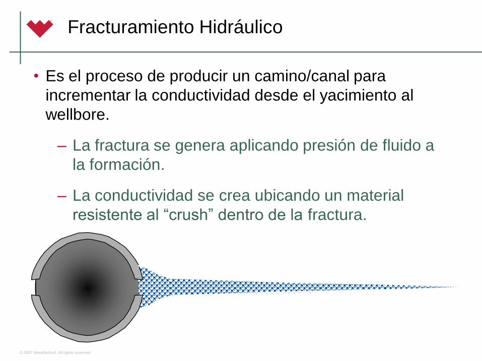
• Es el proceso de producir un camino/canal para
incrementar la conductividad desde el yacimiento al
wellbore.
– La fractura se genera aplicando presión de fluido a
la formación.
– La conductividad se crea ubicando un material
resistente al “crush” dentro de la fractura.
© 2007 Weatherford. All rights reserved.
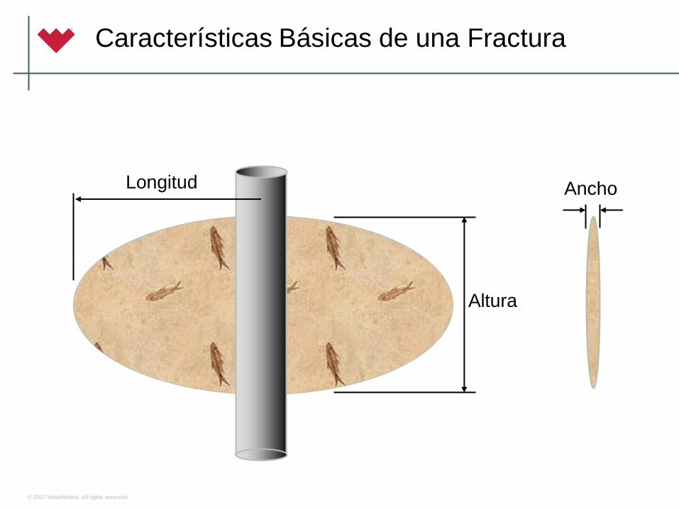
Características Básicas de una Fractura
Altura
Longitud Ancho
© 2007 Weatherford. All rights reserved.
Características de la Fractura
• Conductividad de la Fractura Apuntalada:
– Capacidad de flujo de la fractura.
– Igual a la permeabilidad del apuntalante por el ancho
promedio apuntalado.
– A mayor conductividad, mayor productividad – hasta
un punto.
• Longitud de la Fractura Apuntalada:
– A mayor longitud, mayor productividad siempre que
exista suficiente conductividad.
© 2007 Weatherford. All rights reserved.
• En Formaciones de Alta Permeabilidad se requieren
fracturas cortas y anchas.
– Productividad limitada por la conductividad de la
fractura.
– Fracturas diseñada para un máximo ancho
apuntalado.
– Longitud apuntalada es menos importante.
Alta vs. Baja Permeabilidad
© 2007 Weatherford. All rights reserved.
Alta vs. Baja Permeabilidad
• En Formaciones Baja Permeabilidad ‘Shale’ se requieren
fracturas largas y delgadas.
– Productividad limitada por la capacidad de la formación
para entregar hidrocarburos a la fractura.
– Fácil para hacer fracturas significativamente más
conductivas que la formación.
– Fracturas diseñadas para un área de flujo máxima
(ejemplo, máxima longitud).
© 2007 Weatherford. All rights reserved.
Factores del Diseño
• Permeabilidad
– Permeabilidad de la Formación.
– Apuntalante en la Fractura.
• Permeabilidad del Apuntalante.
• Condiciones de Producción Post-Tratamiento.
– Fracturas Acidas
• Conductividad de la Fractura.
LA PERMEABILIDAD DE LA FORMACION ES LA PIEZA
MAS IMPORTANTE QUE SE NECESITA PARA DISEÑAR
UN TRABAJO DE FRACTURAMIENTO HIDRAULICO
© 2007 Weatherford. All rights reserved.
Factores del Diseño
• Compatibilidad con Fluidos de Formación
– No deben reaccionar con minerales de la formación.
– No deben afectar la humectabilidad y la permeabilidad
relativa.
– No debe dejar residuo de polímero en la formación o
en el paquete apuntalado.
– El líquido no debe formar bloques inmóviles de fluidos
en la formación.
© 2007 Weatherford. All rights reserved.
Factores del Diseño
• Perforaciones, tienen mucha influencia en el éxito de
los trabajos de fracturamiento hidráulico:
– Minimizar la tortuosidad.
– Controlar la iniciación de la fractura.
– Eliminar múltiples fracturas.
© 2007 Weatherford. All rights reserved.
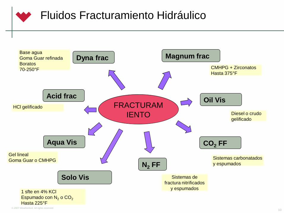
Fluidos Fracturamiento Hidráulico
10
FRACTURAM
IENTO
Dyna frac
Acid frac
Aqua Vis
N2 FF
Magnum frac
CMHPG + Zirconatos
Hasta 375°F
Oil Vis
Diesel o crudo
gelificado
CO2 FF
Base agua
Goma Guar refinada
Boratos
70-250°F
HCl gelificado
Gel lineal
Goma Guar o CMHPG
Sistemas de
fractura nitrificados
y espumados
Sistemas carbonatados
y espumados
Solo Vis
1 sfte en 4% KCl
Espumado con N2 o CO2
Hasta 225°F
© 2007 Weatherford. All rights reserved.
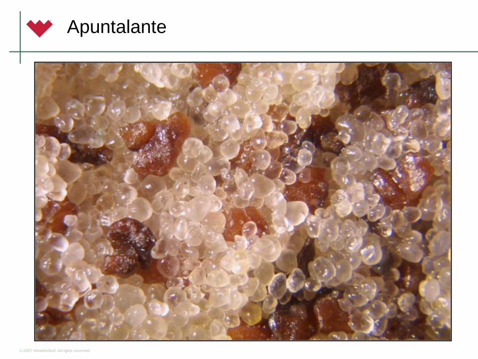
Apuntalante
© 2007 Weatherford. All rights reserved.
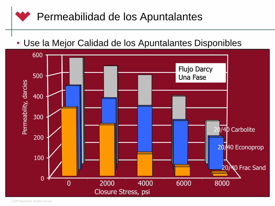
• Use la Mejor Calidad de los Apuntalantes Disponibles
0 2000 4000 6000 8000 0
600
Closure Stress, psi
Permeabilidad de los Apuntalantes
0 2000 4000 6000 8000 0
100
200
300
400
500
600
Perm
eabili
ty, darc
ies
20/40 Carbolite
20/40 Econoprop
20/40 Frac Sand
Flujo Darcy Una Fase
Closure Stress, psi
© 2007 Weatherford. All rights reserved.
0
200
400
600
800
1000
1200
1400
1600
1800
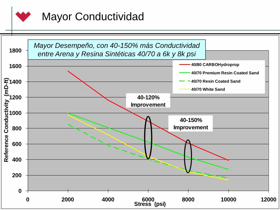
0 2000 4000 6000 8000 10000 12000Stress (psi)
Refe
ren
ce C
on
du
cti
vit
y (m
D-f
t)
40/80 CARBOHydroprop
40/70 Premium Resin Coated Sand
40/70 Resin Coated Sand
40/70 White Sand
40-120%
Improvement
40-150%
Improvement
Mayor Desempeño, con 40-150% más Conductividad
entre Arena y Resina Sintéticas 40/70 a 6k y 8k psi
Mayor Conductividad
© 2007 Weatherford. All rights reserved.
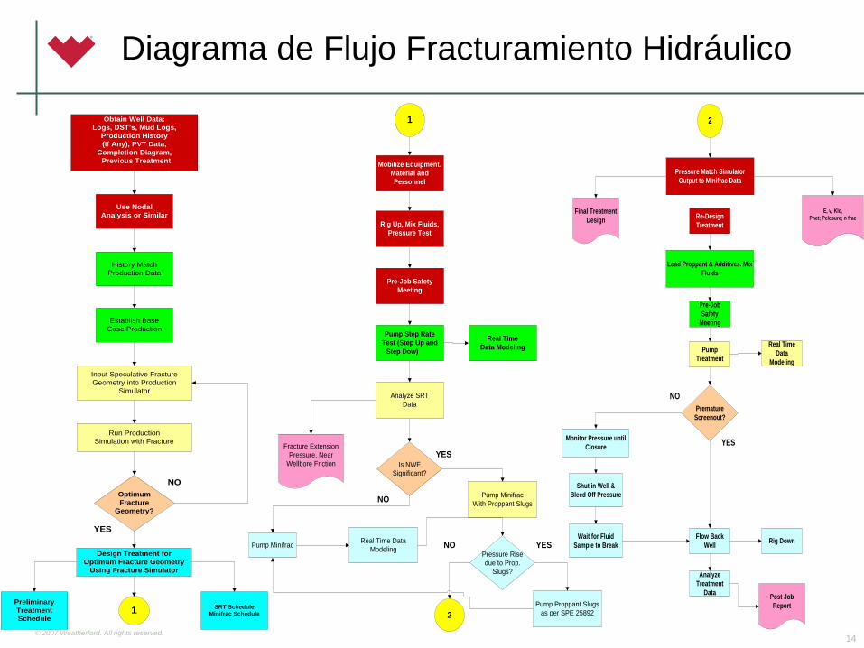
Diagrama de Flujo Fracturamiento Hidráulico
14
Obtain Well Data:
Logs, DST’s, Mud Logs,
Production History
(If Any), PVT Data,
Completion Diagram,
Previous Treatment
Use Nodal
Analysis or Similar
History Match
Production Data
Establish Base
Case Production
Input Speculative Fracture
Geometry into Production
Simulator
Run Production
Simulation with Fracture
Optimum
Fracture
Geometry?
Design Treatment for
Optimum Fracture Geometry
Using Fracture Simulator
Preliminary
Treatment
Schedule
SRT Schedule
Minifrac Schedule1
NO
YES
1
Mobilize Equipment.
Material and
Personnel
Rig Up, Mix Fluids,
Pressure Test
Pre-Job Safety
Meeting
Pump Step Rate
Test (Step Up and
Step Dow)
Real Time
Data Modeling
Analyze SRT
Data
Fracture Extension
Pressure, Near
Wellbore Friction Is NWF
Significant?
Pump Minifrac
With Proppant Slugs
Pressure Rise
due to Prop.
Slugs?
Pump Proppant Slugs
as per SPE 25892
Real Time Data
ModelingPump Minifrac
2
NO
YES
NO YES
2
Pressure Match Simulator
Output to Minifrac Data
E, v, Klc,
Pnet; Pclosure; n fracFinal Treatment
DesignRe-Design
Treatment
Load Proppant & Additives. Mix
Fluids
Pre-Job
Safety
Meeting
Pump
Treatment
Premature
Screenout?
Real Time
Data
Modeling
Monitor Pressure until
Closure
Shut in Well &
Bleed Off Pressure
Wait for Fluid
Sample to Break
Flow Back
Well
Analyze
Treatment
Data
Rig Down
Post Job
Report
YES
NO
© 2007 Weatherford. All rights reserved. 15
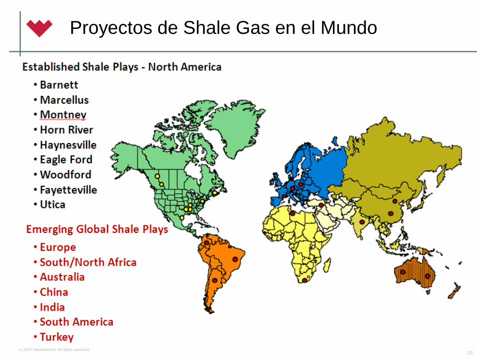
Proyectos de Shale Gas en el Mundo
© 2007 Weatherford. All rights reserved.
R. Fulks Oct 2010 GBD
• Barnett
• Marcellus
• Montney
• Horn River
• Haynesville
• Eagle Ford
• Woodford
• Fayetteville
• Utica
• Niobrara
• Antrim
• Monterey
• Mancos
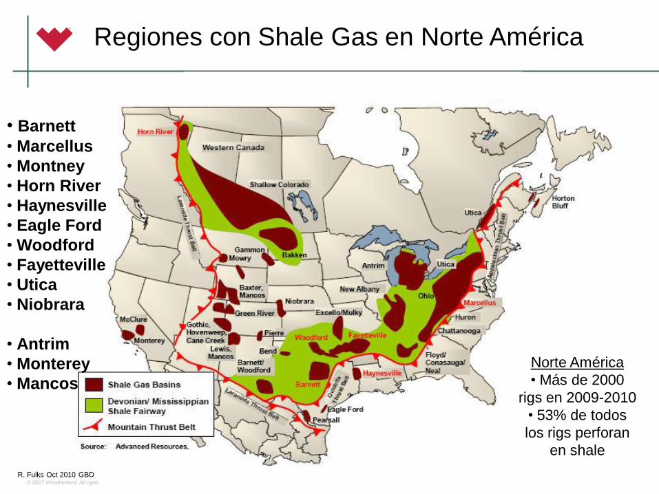
Regiones con Shale Gas en Norte América
Norte América
• Más de 2000
rigs en 2009-2010
• 53% de todos
los rigs perforan
en shale

© 2007 Weatherford. All rights reserved. 17
Proyectos de Shale Gas en Colombia
AREAS CON MAYOR POTENCIAL EN SHALE GAS
•Valle del Magdalena Medio
•Cundinamarca
•Catatumbo
COMPAÑIAS OPERADORAS
•Ecopetrol S.A.
•Nexen
•Occidental de Colombia
POZOS PERFORADOS
•Pozo La Luna-1 de Ecopetrol S.A.
•Pozo Sueva-1 de Nexen
•Pozo Junín-1 de Nexen
© 2007 Weatherford. All rights reserved. 18
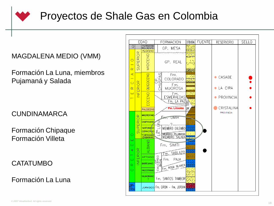
Proyectos de Shale Gas en Colombia
MAGDALENA MEDIO (VMM)
Formación La Luna, miembros
Pujamaná y Salada
CUNDINAMARCA
Formación Chipaque
Formación Villeta
CATATUMBO
Formación La Luna
© 2007 Weatherford. All rights reserved.
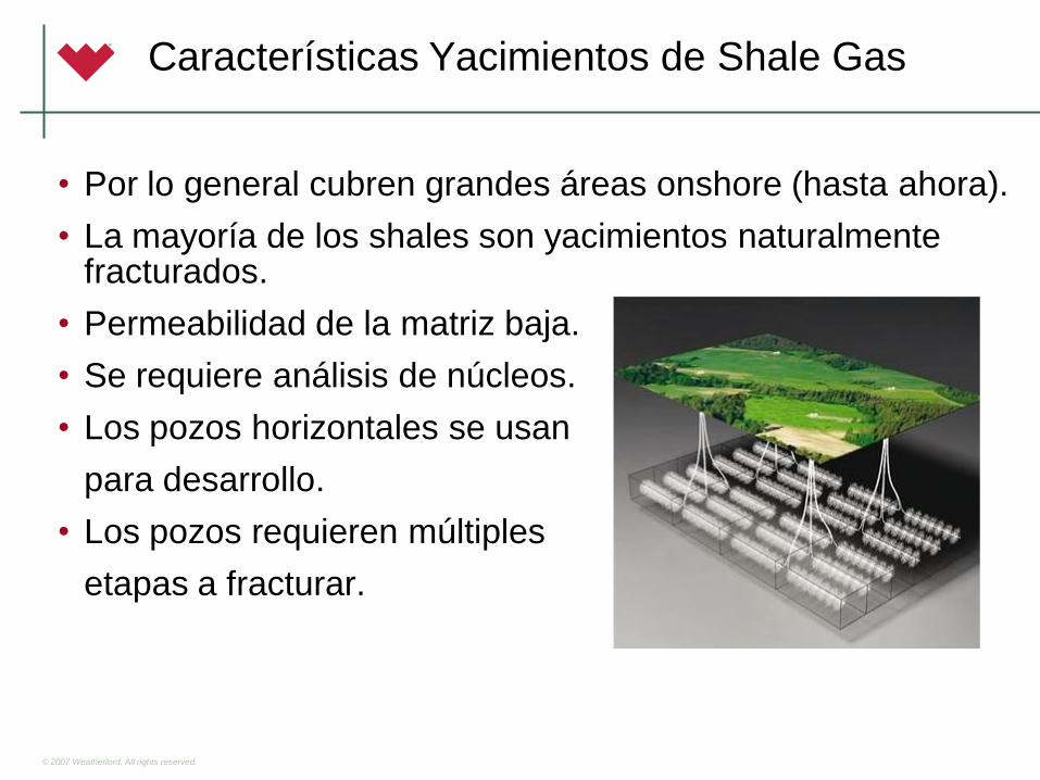
Características Yacimientos de Shale Gas
• Por lo general cubren grandes áreas onshore (hasta ahora).
• La mayoría de los shales son yacimientos naturalmente fracturados.
• Permeabilidad de la matriz baja.
• Se requiere análisis de núcleos.
• Los pozos horizontales se usan
para desarrollo.
• Los pozos requieren múltiples
etapas a fracturar.
© 2007 Weatherford. All rights reserved.
• La selección de candidatos significa garantizar suficientes
reservas para justificar el tratamiento:
– Radio de drenaje
– Espesor neto
– Porosidad
– Saturación
– Presión de Yacimiento
Selección de Pozos Candidatos
© 2007 Weatherford. All rights reserved.
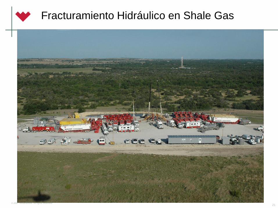
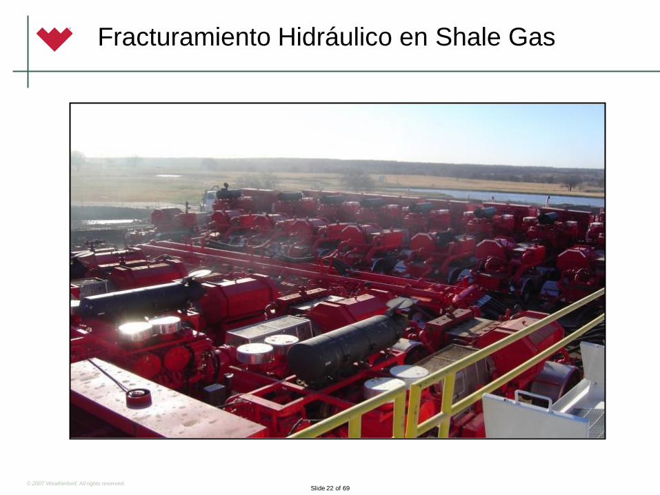
Fracturamiento Hidráulico en Shale Gas
21
© 2007 Weatherford. All rights reserved. Slide 22 of 69
Fracturamiento Hidráulico en Shale Gas
© 2007 Weatherford. All rights reserved. Slide 23 of 69
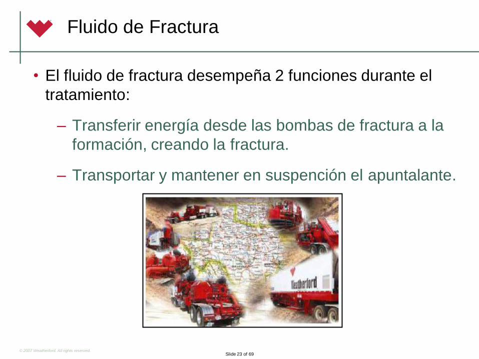
Fluido de Fractura
• El fluido de fractura desempeña 2 funciones durante el
tratamiento:
– Transferir energía desde las bombas de fractura a la
formación, creando la fractura.
– Transportar y mantener en suspención el apuntalante.
© 2007 Weatherford. All rights reserved. Slide 24 of 69
• Con el fin de generar el incremento máximo de
producción posible, un fluido de fractura debe:
– Ser compatible con minerales de la formación.
– Minimizar el daño en el paquete apuntalado y que
rodea la formación.
– Recuperarse fácilmente después del tratamiento.
Fluido de Fractura
© 2007 Weatherford. All rights reserved.
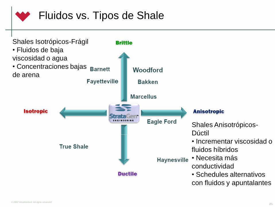
Fluidos vs. Tipos de Shale
25
Shales Isotrópicos-Frágil
• Fluidos de baja
viscosidad o agua
• Concentraciones bajas
de arena
Shales Anisotrópicos-
Dúctil
• Incrementar viscosidad o
fluidos híbridos
• Necesita más
conductividad
• Schedules alternativos
con fluidos y apuntalantes
© 2007 Weatherford. All rights reserved.
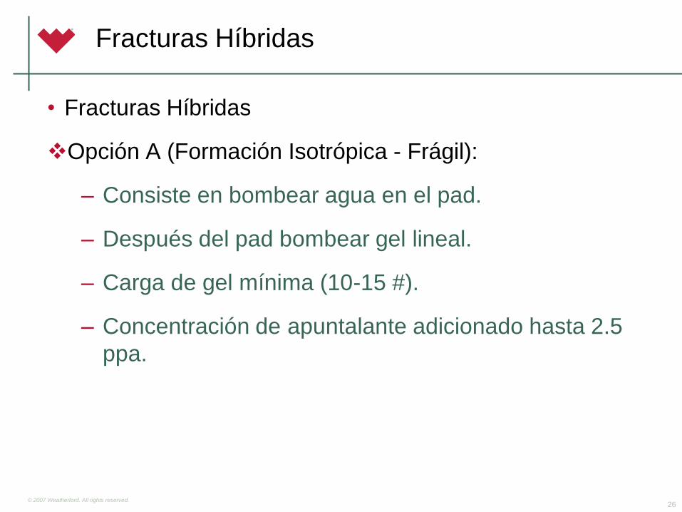
Fracturas Híbridas
• Fracturas Híbridas
Opción A (Formación Isotrópica - Frágil):
– Consiste en bombear agua en el pad.
– Después del pad bombear gel lineal.
– Carga de gel mínima (10-15 #).
– Concentración de apuntalante adicionado hasta 2.5
ppa.
26
© 2007 Weatherford. All rights reserved.
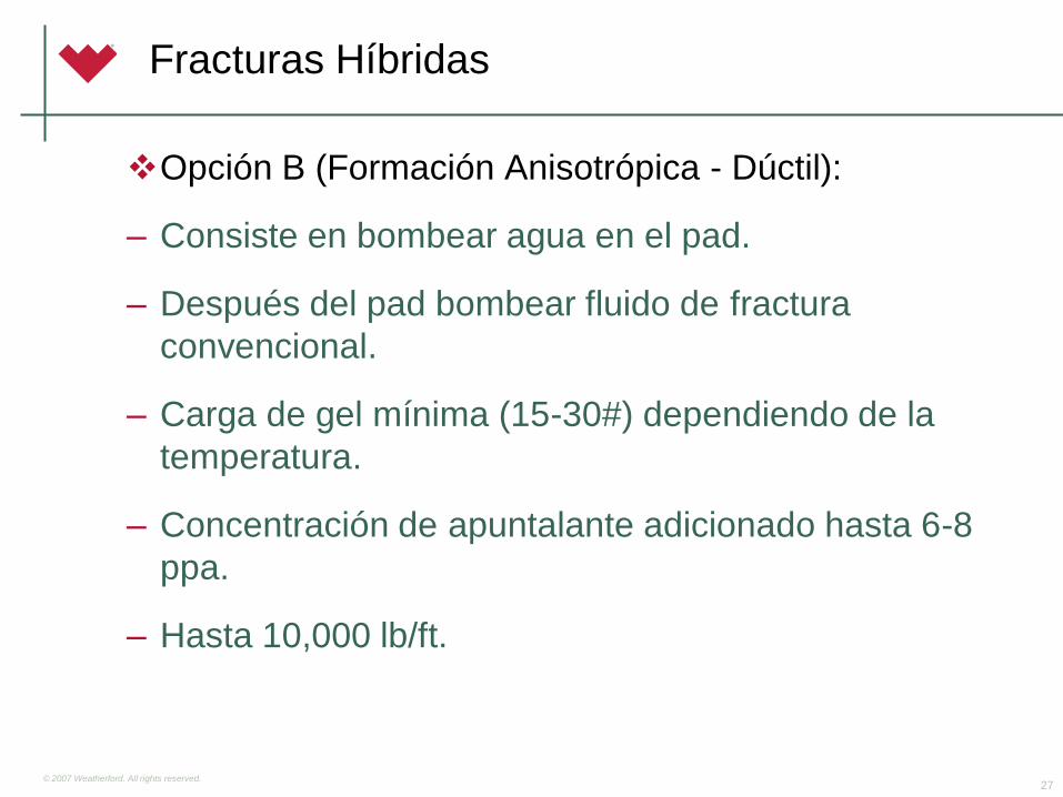
Opción B (Formación Anisotrópica - Dúctil):
– Consiste en bombear agua en el pad.
– Después del pad bombear fluido de fractura
convencional.
– Carga de gel mínima (15-30#) dependiendo de la
temperatura.
– Concentración de apuntalante adicionado hasta 6-8
ppa.
– Hasta 10,000 lb/ft.
27
Fracturas Híbridas
© 2007 Weatherford. All rights reserved. 28
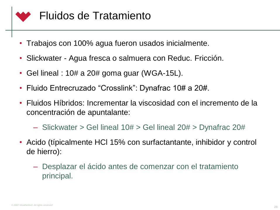
Fluidos de Tratamiento
• Trabajos con 100% agua fueron usados inicialmente.
• Slickwater - Agua fresca o salmuera con Reduc. Fricción.
• Gel lineal : 10# a 20# goma guar (WGA-15L).
• Fluido Entrecruzado “Crosslink”: Dynafrac 10# a 20#.
• Fluidos Híbridos: Incrementar la viscosidad con el incremento de la
concentración de apuntalante:
– Slickwater > Gel lineal 10# > Gel lineal 20# > Dynafrac 20#
• Acido (típicalmente HCl 15% con surfactantante, inhibidor y control
de hierro):
– Desplazar el ácido antes de comenzar con el tratamiento
principal.
© 2007 Weatherford. All rights reserved.
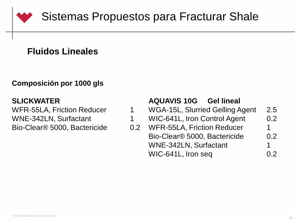
Sistemas Propuestos para Fracturar Shale
29
Composición por 1000 gls
SLICKWATER
WFR-55LA, Friction Reducer 1
WNE-342LN, Surfactant 1
Bio-Clear® 5000, Bactericide 0.2
AQUAVIS 10G Gel lineal
WGA-15L, Slurried Gelling Agent 2.5
WIC-641L, Iron Control Agent 0.2
WFR-55LA, Friction Reducer 1
Bio-Clear® 5000, Bactericide 0.2
WNE-342LN, Surfactant 1
WIC-641L, Iron seq 0.2
Fluidos Lineales
© 2007 Weatherford. All rights reserved.
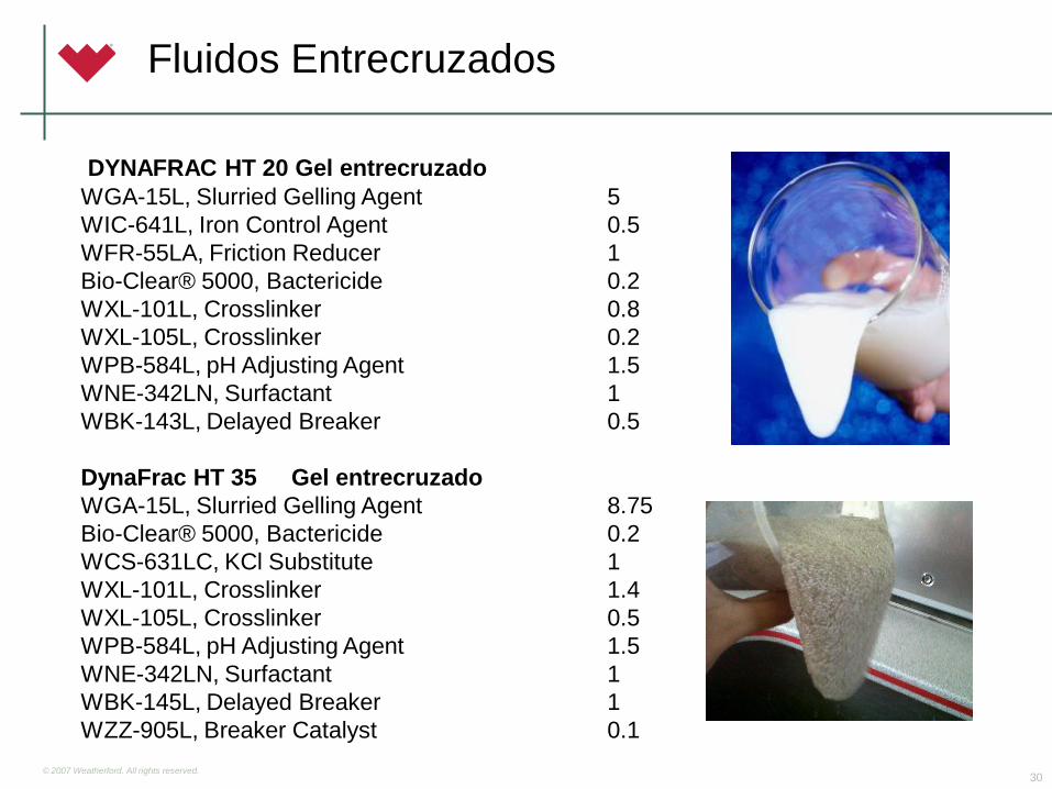
Fluidos Entrecruzados
30
DYNAFRAC HT 20 Gel entrecruzado
WGA-15L, Slurried Gelling Agent 5
WIC-641L, Iron Control Agent 0.5
WFR-55LA, Friction Reducer 1
Bio-Clear® 5000, Bactericide 0.2
WXL-101L, Crosslinker 0.8
WXL-105L, Crosslinker 0.2
WPB-584L, pH Adjusting Agent 1.5
WNE-342LN, Surfactant 1
WBK-143L, Delayed Breaker 0.5
DynaFrac HT 35 Gel entrecruzado
WGA-15L, Slurried Gelling Agent 8.75
Bio-Clear® 5000, Bactericide 0.2
WCS-631LC, KCl Substitute 1
WXL-101L, Crosslinker 1.4
WXL-105L, Crosslinker 0.5
WPB-584L, pH Adjusting Agent 1.5
WNE-342LN, Surfactant 1
WBK-145L, Delayed Breaker 1
WZZ-905L, Breaker Catalyst 0.1
© 2007 Weatherford. All rights reserved. 32
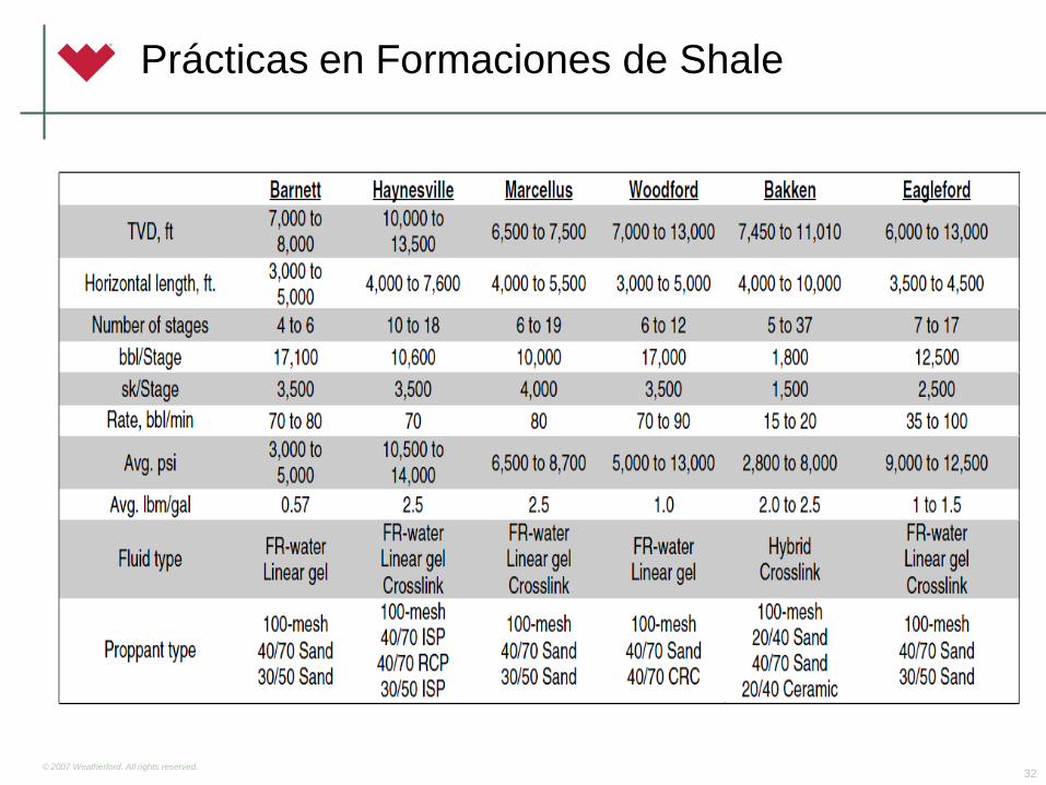
Prácticas en Formaciones de Shale
© 2007 Weatherford. All rights reserved.
Equipos Fracturamiento Hidráulico
© 2007 Weatherford. All rights reserved.
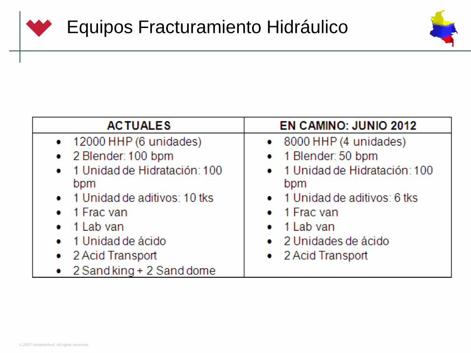
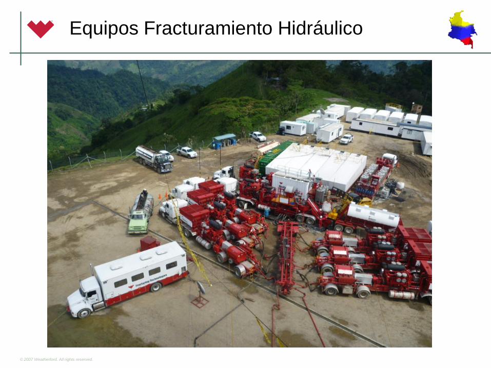
Equipos Fracturamiento Hidráulico
© 2007 Weatherford. All rights reserved.
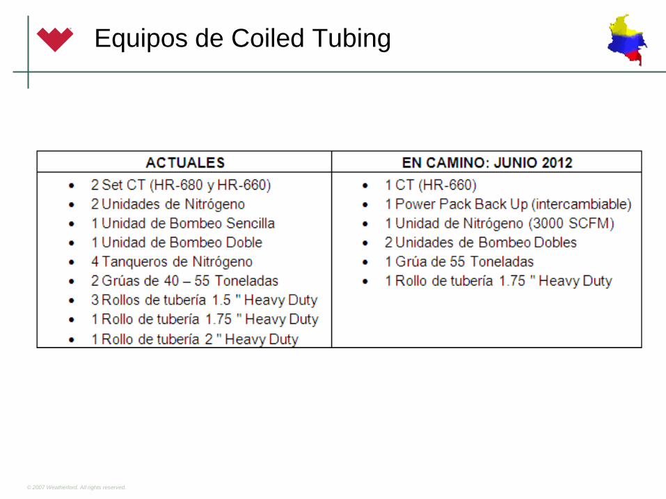
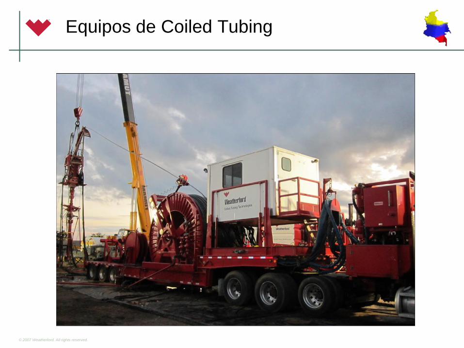
Equipos de Coiled Tubing
© 2007 Weatherford. All rights reserved.
Equipos de Coiled Tubing
© 2007 Weatherford. All rights reserved.
LABORATORIOS WEATHERFORD
© 2007 Weatherford. All rights reserved.
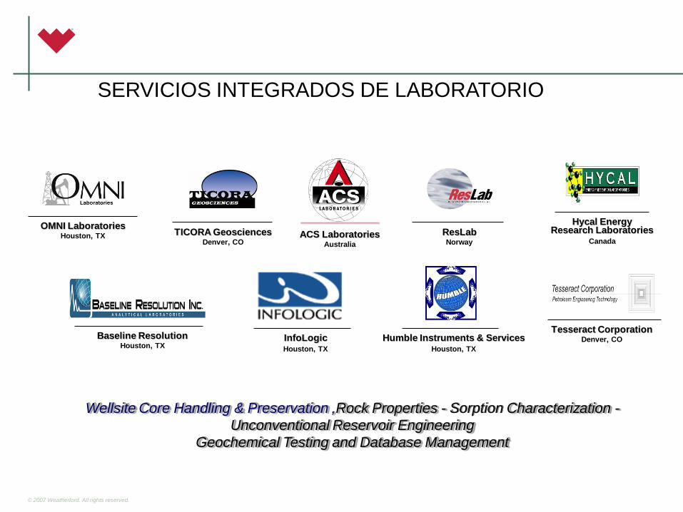
Wellsite Core Handling & Preservation ,Rock Properties - Sorption Characterization -
Unconventional Reservoir Engineering
Geochemical Testing and Database Management
TICORA Geosciences Denver, CO
OMNI Laboratories Houston, TX ResLab
Norway
Humble Instruments & Services Houston, TX
Hycal Energy Research Laboratories
Canada
Tesseract Corporation Denver, CO Baseline Resolution
Houston, TX InfoLogic Houston, TX
_______________
ACS Laboratories Australia
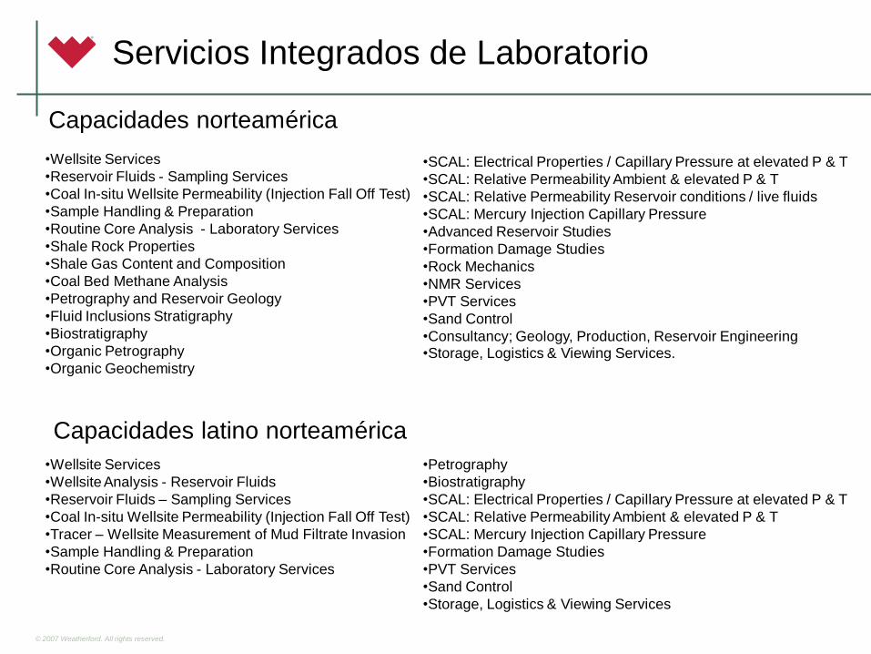
SERVICIOS INTEGRADOS DE LABORATORIO
© 2007 Weatherford. All rights reserved.
Capacidades norteamérica
Servicios Integrados de Laboratorio
Capacidades latino norteamérica
•Wellsite Services
•Reservoir Fluids - Sampling Services
•Coal In-situ Wellsite Permeability (Injection Fall Off Test)
•Sample Handling & Preparation
•Routine Core Analysis - Laboratory Services
•Shale Rock Properties
•Shale Gas Content and Composition
•Coal Bed Methane Analysis
•Petrography and Reservoir Geology
•Fluid Inclusions Stratigraphy
•Biostratigraphy
•Organic Petrography
•Organic Geochemistry
•SCAL: Electrical Properties / Capillary Pressure at elevated P & T
•SCAL: Relative Permeability Ambient & elevated P & T
•SCAL: Relative Permeability Reservoir conditions / live fluids
•SCAL: Mercury Injection Capillary Pressure
•Advanced Reservoir Studies
•Formation Damage Studies
•Rock Mechanics
•NMR Services
•PVT Services
•Sand Control
•Consultancy; Geology, Production, Reservoir Engineering •Storage, Logistics & Viewing Services.
•Wellsite Services
•Wellsite Analysis - Reservoir Fluids
•Reservoir Fluids – Sampling Services
•Coal In-situ Wellsite Permeability (Injection Fall Off Test)
•Tracer – Wellsite Measurement of Mud Filtrate Invasion
•Sample Handling & Preparation
•Routine Core Analysis - Laboratory Services
•Petrography
•Biostratigraphy
•SCAL: Electrical Properties / Capillary Pressure at elevated P & T
•SCAL: Relative Permeability Ambient & elevated P & T
•SCAL: Mercury Injection Capillary Pressure
•Formation Damage Studies
•PVT Services
•Sand Control
•Storage, Logistics & Viewing Services
© 2007 Weatherford. All rights reserved.
Trondheim
Oslo
Bergen
Stavanger
Tripoli Kuwait
Dhahran
Abu Dhabi
Muscat
Winfrith
East Grinstead (London)
Rio de Janeiro
Port of Spain Villahermosa
Maracaibo
Poza Rica
St. John’s, Newfoundland
Anchorage
Calgary
Bakersfield
Casper
Denver
Corpus Christi
Jackson
New Orleans Midland
Houston
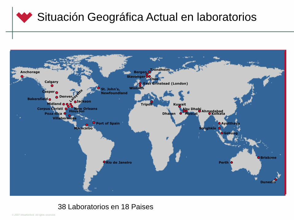
Situación Geográfica Actual en laboratorios
Trondheim
Oslo
Bergen
Stavanger
Tripoli Kuwait
Dhahran
Abu Dhabi
Muscat
Winfrith
East Grinstead (London)
Rio de Janeiro
Port of Spain Villahermosa
Maracaibo
Poza Rica
St. John’s, Newfoundland
Anchorage
Calgary
Bakersfield
Casper
Denver
Corpus Christi
Jackson
New Orleans Midland
Houston
Trondheim
Oslo
Bergen
Stavanger
Tripoli Kuwait
Dhahran
Abu Dhabi
Muscat
Winfrith
East Grinstead (London)
Rio de Janeiro
Port of Spain Villahermosa
Maracaibo
Poza Rica
St. John’s, Newfoundland
Anchorage
Calgary
Bakersfield
Casper
Denver
Corpus Christi
Jackson
New Orleans Midland
Houston
Trondheim
Oslo
Bergen
Stavanger
Tripoli Kuwait
Dharan
Abu Dhabi
Muscat
Winfrith
East Grinstead (London)
Rio de Janeiro
Port of Spain
Villahermosa
Maracaibo
Poza Rica
St. John’s, Newfoundland
Anchorage
Calgary
Bakersfield
Casper
Denver
Corpus Christi
Jackson
New Orleans
Midland
Houston
Brisbane
Perth
Dunedin
Kolkata
Gebung
Songhkla
Ahmedabad
Ayutthaya
38 Laboratorios en 18 Paises
© 2007 Weatherford. All rights reserved.
45