Embed Size (px)
Citation preview
Free-Piston Engine
Peter Van BlariganSandia National Laboratories
2010 DOE Vehicle Technologies Program Annual Merit ReviewTuesday, June 8, 2010
Project ID: ACE008
Sponsors: Advanced Combustion Engine R&D and Fuel Technologies Program Managers: Gurpreet Singh and Kevin Stork
This presentation does not contain any proprietary, confidential, or otherwise restricted information
2
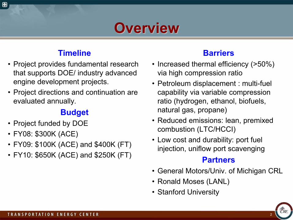
OverviewTimeline
• Project provides fundamental research that supports DOE/ industry advanced engine development projects.
• Project directions and continuation are evaluated annually.
Budget• Project funded by DOE• FY08: $300K (ACE)• FY09: $100K (ACE) and $400K (FT)• FY10: $650K (ACE) and $250K (FT)
Barriers• Increased thermal efficiency (>50%)
via high compression ratio• Petroleum displacement : multi-fuel
capability via variable compression ratio (hydrogen, ethanol, biofuels, natural gas, propane)
• Reduced emissions: lean, premixed combustion (LTC/HCCI)
• Low cost and durability: port fuel injection, uniflow port scavenging
Partners• General Motors/Univ. of Michigan CRL• Ronald Moses (LANL) • Stanford University
3
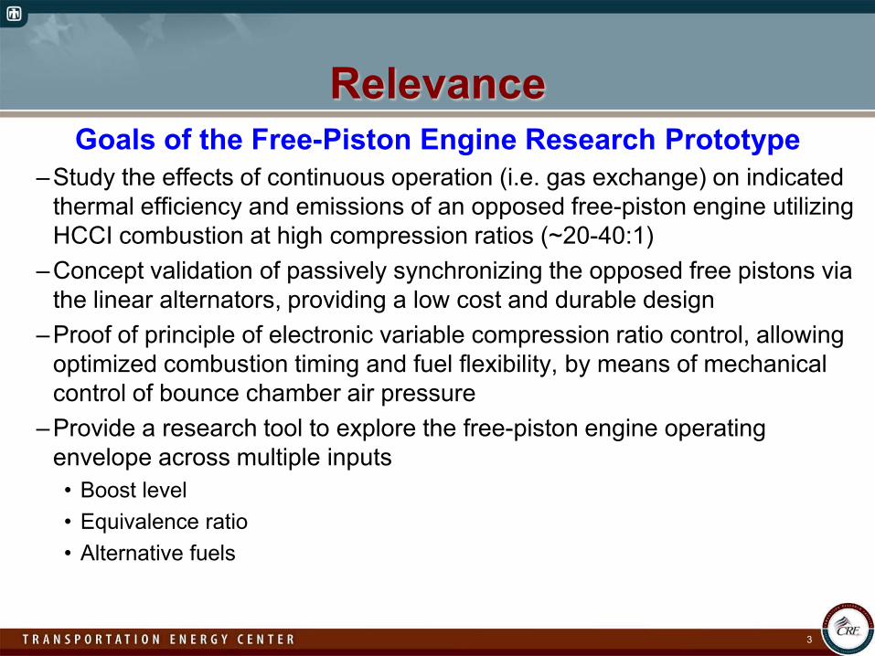
RelevanceGoals of the Free-Piston Engine Research Prototype
–Study the effects of continuous operation (i.e. gas exchange) on indicated thermal efficiency and emissions of an opposed free-piston engine utilizing HCCI combustion at high compression ratios (~20-40:1)
–Concept validation of passively synchronizing the opposed free pistons via the linear alternators, providing a low cost and durable design
–Proof of principle of electronic variable compression ratio control, allowing optimized combustion timing and fuel flexibility, by means of mechanical control of bounce chamber air pressure
–Provide a research tool to explore the free-piston engine operating envelope across multiple inputs• Boost level• Equivalence ratio• Alternative fuels
MilestonesTime Milestone or Go/No-Go Decision
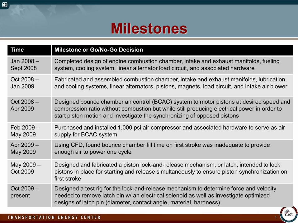
Jan 2008 –Sept 2008
Completed design of engine combustion chamber, intake and exhaust manifolds, fueling system, cooling system, linear alternator load circuit, and associated hardware
Oct 2008 –Jan 2009
Fabricated and assembled combustion chamber, intake and exhaust manifolds, lubrication and cooling systems, linear alternators, pistons, magnets, load circuit, and intake air blower
Oct 2008 –Apr 2009
Designed bounce chamber air control (BCAC) system to motor pistons at desired speed and compression ratio without combustion but while still producing electrical power in order to start piston motion and investigate the synchronizing of opposed pistons
Feb 2009 –May 2009
Purchased and installed 1,000 psi air compressor and associated hardware to serve as air supply for BCAC system
Apr 2009 –May 2009
Using CFD, found bounce chamber fill time on first stroke was inadequate to provide enough air to power one cycle
May 2009 –Oct 2009
Designed and fabricated a piston lock-and-release mechanism, or latch, intended to lock pistons in place for starting and release simultaneously to ensure piston synchronization on first stroke
Oct 2009 –present
Designed a test rig for the lock-and-release mechanism to determine force and velocity needed to remove latch pin w/ an electrical solenoid as well as investigate optimized designs of latch pin (diameter, contact angle, material, hardness)
4
5
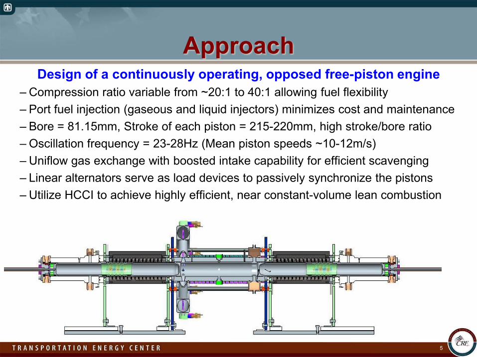
ApproachDesign of a continuously operating, opposed free-piston engine
– Compression ratio variable from ~20:1 to 40:1 allowing fuel flexibility– Port fuel injection (gaseous and liquid injectors) minimizes cost and maintenance– Bore = 81.15mm, Stroke of each piston = 215-220mm, high stroke/bore ratio– Oscillation frequency = 23-28Hz (Mean piston speeds ~10-12m/s)– Uniflow gas exchange with boosted intake capability for efficient scavenging – Linear alternators serve as load devices to passively synchronize the pistons– Utilize HCCI to achieve highly efficient, near constant-volume lean combustion
6
ApproachVariable compression ratio control
–Require capability to test a range of compression ratios to enable fuel flexibility and optimize combustion timing
–Desire capability to oscillate, or “motor”, pistons at required compression ratio without combustion but with constant electrical load to maintain stabilization force of synchronized linear alternators
–Compression ratio control during motoring is achieved by controlling both air injection into and vent pressure out of the bounce chambers.
–Load control when adding combustion energy at constant compression ratio is achieved by varying only vent pressure out of bounce chambers as fuel injection is increased, until full power is achieved via combustion only.
7
ApproachOpposed piston synchronization via passive coupling
of the linear alternators to a common load–Opposed piston configuration has two main benefits:
• Inherent mechanical balance of overall engine• Opportunity to utilize a central combustion chamber with highly efficient
uniflow scavenging via intake and exhaust ports (no valves) –Synchronization on the first stroke is key to stabilizing force for the
subsequent cycles. –A latch mechanism was designed to lock each piston in place for
starting and to release both pistons simultaneously to ensure first stroke synchronization.
–A test stand to verify the performance and optimize the design of the latch mechanism prior to final bounce chamber and piston fabrication was assembled and utilized.
8
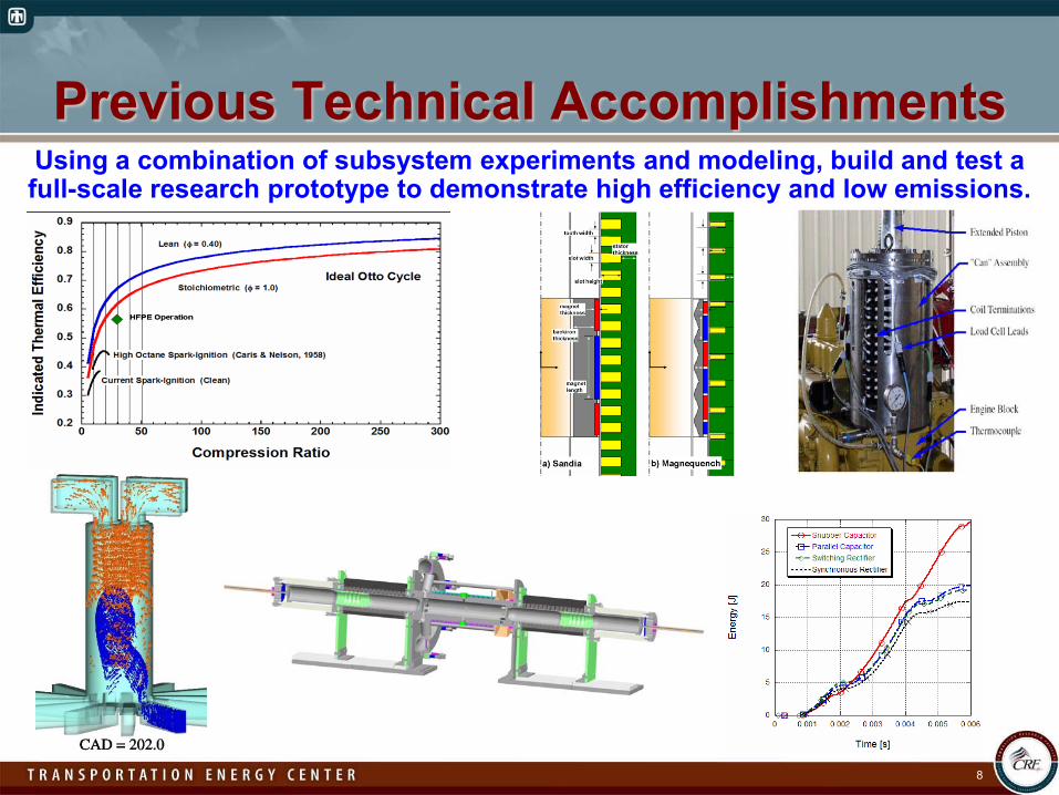
Previous Technical AccomplishmentsUsing a combination of subsystem experiments and modeling, build and test a full-scale research prototype to demonstrate high efficiency and low emissions.
9
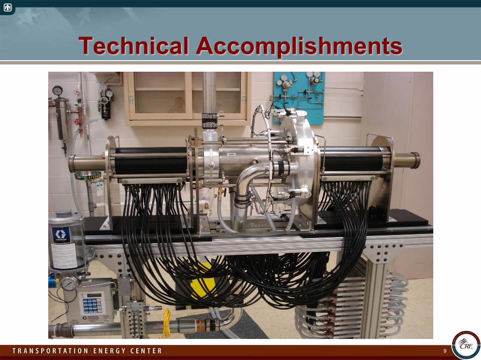
Technical Accomplishments
10
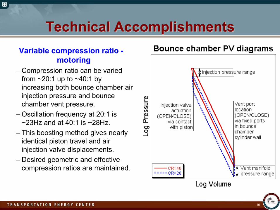
Technical AccomplishmentsVariable compression ratio -
motoring– Compression ratio can be varied
from ~20:1 up to ~40:1 by increasing both bounce chamber air injection pressure and bounce chamber vent pressure.
– Oscillation frequency at 20:1 is ~23Hz and at 40:1 is ~28Hz.
– This boosting method gives nearly identical piston travel and air injection valve displacements.
– Desired geometric and effective compression ratios are maintained.
11
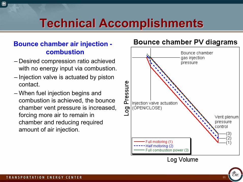
Technical AccomplishmentsBounce chamber air injection -
combustion– Desired compression ratio achieved
with no energy input via combustion.– Injection valve is actuated by piston
contact.– When fuel injection begins and
combustion is achieved, the bounce chamber vent pressure is increased, forcing more air to remain in chamber and reducing required amount of air injection.
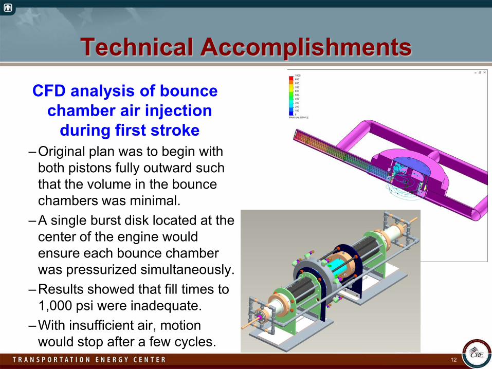
Technical AccomplishmentsCFD analysis of bounce
chamber air injection during first stroke
–Original plan was to begin with both pistons fully outward such that the volume in the bounce chambers was minimal.
–A single burst disk located at the center of the engine would ensure each bounce chamber was pressurized simultaneously.
–Results showed that fill times to 1,000 psi were inadequate.
–With insufficient air, motion would stop after a few cycles.
12
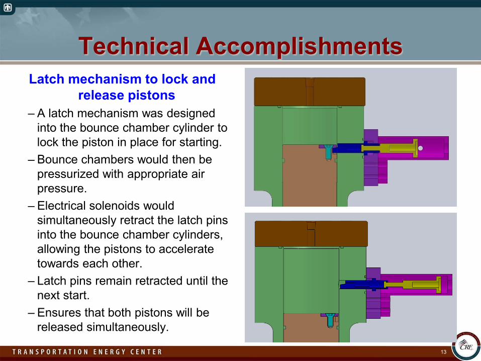
Technical AccomplishmentsLatch mechanism to lock and
release pistons– A latch mechanism was designed
into the bounce chamber cylinder to lock the piston in place for starting.
– Bounce chambers would then be pressurized with appropriate air pressure.
– Electrical solenoids would simultaneously retract the latch pins into the bounce chamber cylinders, allowing the pistons to accelerate towards each other.
– Latch pins remain retracted until the next start.
– Ensures that both pistons will be released simultaneously.
13
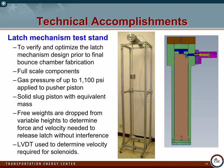
Technical AccomplishmentsLatch mechanism test stand
–To verify and optimize the latch mechanism design prior to final bounce chamber fabrication
–Full scale components–Gas pressure of up to 1,100 psi
applied to pusher piston–Solid slug piston with equivalent
mass–Free weights are dropped from
variable heights to determine force and velocity needed to release latch without interference
–LVDT used to determine velocity required for solenoids.
14
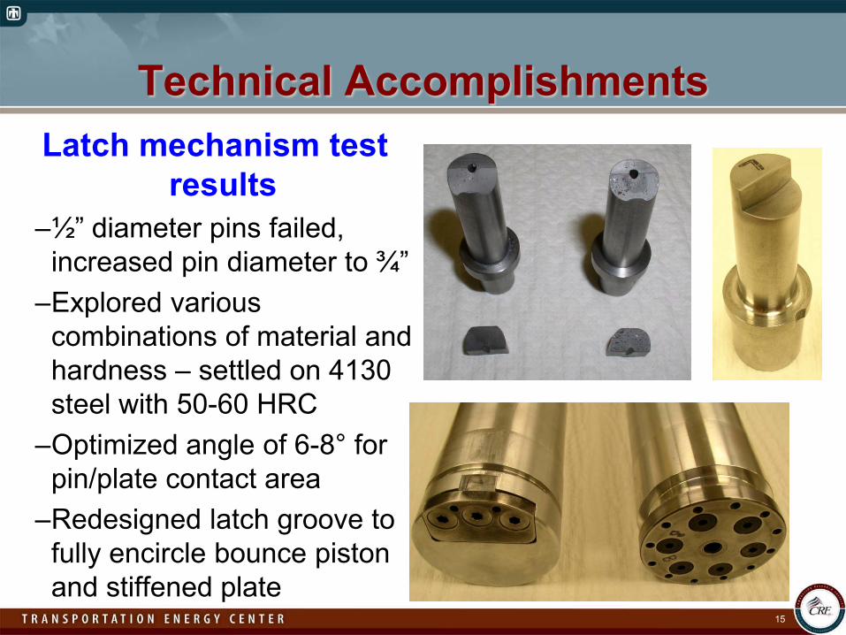
Technical AccomplishmentsLatch mechanism test
results–½” diameter pins failed,
increased pin diameter to ¾”–Explored various
combinations of material and hardness – settled on 4130 steel with 50-60 HRC
–Optimized angle of 6-8° for pin/plate contact area
–Redesigned latch groove to fully encircle bounce piston and stiffened plate
15
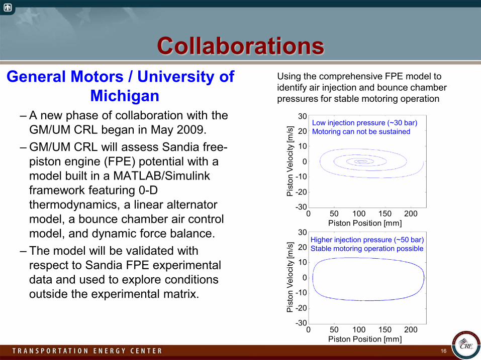
CollaborationsGeneral Motors / University of
Michigan– A new phase of collaboration with the
GM/UM CRL began in May 2009.– GM/UM CRL will assess Sandia free-
piston engine (FPE) potential with a model built in a MATLAB/Simulink framework featuring 0-D thermodynamics, a linear alternator model, a bounce chamber air control model, and dynamic force balance.
– The model will be validated with respect to Sandia FPE experimental data and used to explore conditions outside the experimental matrix.
16
0 50 100 150 200Piston Position [mm]
30
20
10
0
-10
-20
-30
Pis
ton
Velo
city
[m/s
]
0 50 100 150 200Piston Position [mm]
30
20
10
0
-10
-20
-30
Pis
ton
Velo
city
[m/s
]
Using the comprehensive FPE model toidentify air injection and bounce chamberpressures for stable motoring operation
Low injection pressure (~30 bar)Motoring can not be sustained
Higher injection pressure (~50 bar)Stable motoring operation possible
17
Future Work•Complete engine fabrication and assembly
–Latch pin design and solenoid–Bounce chamber injection valve and cylinder–Bounce chamber air control tanks and controllers–Combustion control and data acquisition system
• Initially run the engine under air injection motoring mode only to test the synchronizing capability of the linear alternator coupling• Perform combustion experiments at various compression
ratios and equivalence ratios with both conventional and alternative fuels
Hydrogen EthanolNatural Gas BiofuelsPropane RenewablesGasoline
18
Summary• Free-Piston Engine (FPE) research prototype design and
fabrication nearing completion.•Bounce chamber air control (BCAC) concept developed to
achieve desired resonant piston motion and test linear alternator coupling before combustion is initiated.•BCAC will also provide variable compression ratio control,
allowing for optimized combustion timing and fuel flexibility.• Piston latch mechanism designed and full-scale hardware
testing ongoing.•Collaboration with GM/UM CRL on modeling of the Sandia
FPE prototype engine has commenced.