Embed Size (px)
Citation preview
FreedomOwner'sManual
- May, 2001 -
¥ MasonryFireplace Insert
SAFETY NOTICE:If this appliance is not properly installed, a housefire may result. For your safety, follow theinstallation directions. Contact local building orfire officials about restrictions and installationinspection requirements in your area.
Freedom Fireplace Insert
10850 117th Place N.E. Kirkland, WA 98033
Part # 93508020 $10.00 Listed
INTRODUCTION & IMPORTANT INFORMATION PAGE 1
IntroductionWe welcome you as a new owner of a Lopi Freedom wood-burning appliance. In purchasing a LopiFreedom you have joined the growing ranks of concerned individuals whose selection of an energysystem reflects both a concern for the environment and aesthetics. The Lopi Freedom is one of the finestappliances the world over. This manual will explain the installation, operation, and maintenance of thisappliance. Please familiarize yourself with the Owner's Manual before operating your appliance andsave the manual for future reference. Included are helpful hints and suggestions which will make theinstallation and operation of your new appliance an easier and more enjoyable experience. We offer ourcontinual support and guidance to help you achieve the maximum benefit and enjoyment from yourappliance.
Important InformationNo other Lopi Freedom appliance has the sameserial number as yours. The serial number isstamped onto the label on the right side of theappliance.
This serial number will be needed in case yourequire service of any type.
Model: LOPI Freedom
Serial Number:
Purchase Date:
Purchased From:
Mail your Warranty Card Today, and SaveYour Bill of Sale.
To receive full warranty coverage, you willneed to show evidence of the date youpurchased your appliance. Do not mail yourBill of Sale to us.
We suggest that you attach your Bill of Sale tothis page so that you will have all theinformation you need in one place should theneed for service or information occur.
PAGE 2 SAFETY PRECAUTIONS
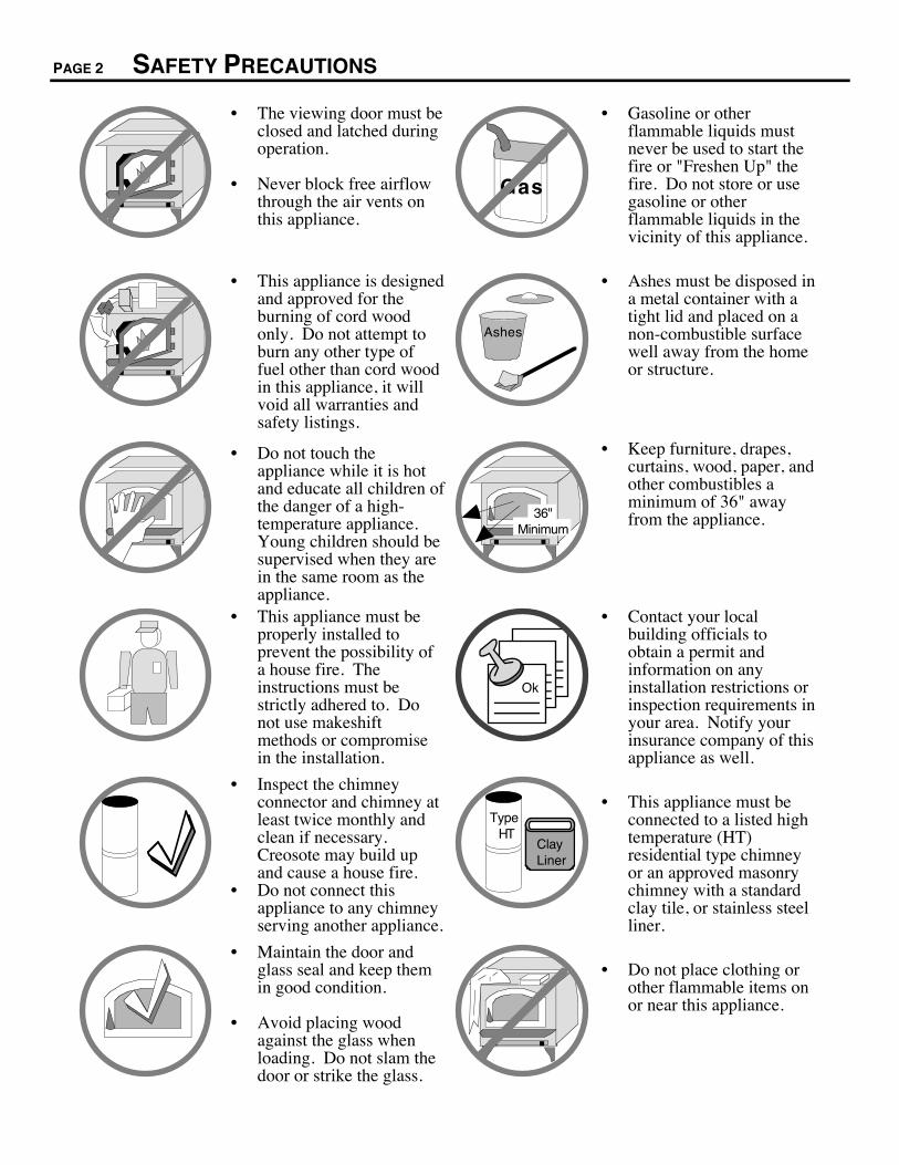
¥ The viewing door must beclosed and latched duringoperation.
¥ Never block free airflowthrough the air vents onthis appliance.
Gas
¥ Gasoline or otherflammable liquids mustnever be used to start thefire or "Freshen Up" thefire. Do not store or usegasoline or otherflammable liquids in thevicinity of this appliance.
¥ This appliance is designedand approved for theburning of cord woodonly. Do not attempt toburn any other type offuel other than cord woodin this appliance, it willvoid all warranties andsafety listings.
Ashes
¥ Ashes must be disposed ina metal container with atight lid and placed on anon-combustible surfacewell away from the homeor structure.
¥ Do not touch theappliance while it is hotand educate all children ofthe danger of a high-temperature appliance.Young children should besupervised when they arein the same room as theappliance.
36" Minimum
¥ Keep furniture, drapes,curtains, wood, paper, andother combustibles aminimum of 36" awayfrom the appliance.
¥ This appliance must beproperly installed toprevent the possibility ofa house fire. Theinstructions must bestrictly adhered to. Donot use makeshiftmethods or compromisein the installation.
Ok
¥ Contact your localbuilding officials toobtain a permit andinformation on anyinstallation restrictions orinspection requirements inyour area. Notify yourinsurance company of thisappliance as well.
¥ Inspect the chimneyconnector and chimney atleast twice monthly andclean if necessary.Creosote may build upand cause a house fire.
¥ Do not connect thisappliance to any chimneyserving another appliance.
Type HT
Clay Liner
¥ This appliance must beconnected to a listed hightemperature (HT)residential type chimneyor an approved masonrychimney with a standardclay tile, or stainless steelliner.
¥ Maintain the door andglass seal and keep themin good condition.
¥ Avoid placing woodagainst the glass whenloading. Do not slam thedoor or strike the glass.
¥ Do not place clothing orother flammable items onor near this appliance.
SAFETY PRECAUTIONS (CONTINUED) PAGE 3
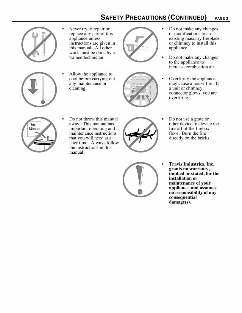
¥ Never try to repair orreplace any part of thisappliance unlessinstructions are given inthis manual. All otherwork must be done by atrained technician.
¥ Do not make any changesor modifications to anexisting masonry fireplaceor chimney to install thisappliance.
¥ Do not make any changesto the appliance toincrease combustion air.
¥ Allow the appliance tocool before carrying outany maintenance orcleaning.
¥ Overfiring the appliancemay cause a house fire. Ifa unit or chimneyconnector glows, you areoverfiring.
ThisManual
¥ Do not throw this manualaway. This manual hasimportant operating andmaintenance instructionsthat you will need at alater time. Always followthe instructions in thismanual.
¥ Do not use a grate orother device to elevate thefire off of the fireboxfloor. Burn the firedirectly on the bricks.
¥ Travis Industries, Inc.grants no warranty,implied or stated, for theinstallation ormaintenance of yourappliance, and assumesno responsibility of anyconsequentialdamage(s).
PAGE 4 TABLE OF CONTENTS
Introduction and Important InformationIntroduction and Important Information ...................... 1
Safety Precautions..................................................... 2
Features and SpecificationsFeatures and Specifications ....................................... 5
Insert InstallationBefore You Begin....................................................... 6
Planning The Installation............................................ 6
Preparation for Installation.......................................... 6
Insert Installation Considerations............................... 6
Optional Equipment Requirements ............................ 6
Insert Placement Requirements ................................. 7
Hearth Requirements................................................. 7
Insert Size Requirements ........................................... 7
Masonry Fireplace Requirements .............................. 8
Leveling Bolt Installation ............................................. 8
Block-Off Plate Installation......................................... 9
INSTALLATION DIAGRAMS
Insert with Positive Connection................................... 10
Insert with Direct Connection...................................... 10
Insert with Face Seal Connection ............................... 11
Operating Your ApplianceBefore You Begin....................................................... 12
Paint Curing ............................................................... 12
Location of Controls .................................................... 12Approximate Air Control Settings ......................... 12Bypass Control ...................................................... 13
Learning to Burn your Appliance................................ 13How to Start a Hot Fire Quickly ............................ 13How to Reload Your Appliance ............................ 14How to Adjust the Heat Output Precisely ............. 14How to Obtain an Overnight Burn ........................ 15Good Burning Habits ............................................ 15
Blower Operation ....................................................... 16
A Word about Wood ................................................... 17
Maintaining Your ApplianceMaintenance Schedule............................................... 19
Remove Ash From The Firebox (If Necessary).......... 19
Clean The Viewing Glass (If Necessary) ................... 19
Clean The Brass (If Necessary) ................................. 19
Check For Creosote Buildup...................................... 19
Door And Glass Inspection ........................................ 20Adjusting the Door Cam ....................................... 20Replacing the Door Gasket .................................. 21Replacing the Glass or Glass Gasket................... 21
Lubricate The Door Hinge.......................................... 21
Touch-Up Paint .......................................................... 22
Blower Cleaning ......................................................... 22
Firebrick And Baffle Inspection And Cleaning............ 22Firebrick Removal and Replacement Inst. ........... 23Baffle Removal and Replacement Instructions..... 23Secondary Air Tube Replacement Instructions .... 25
Replacement Parts List .............................................. 25
TroubleshootingTroubleshooting Table ............................................... 26
WarrantyWarranty..................................................................... 27
Listing InformationListing Information...................................................... 28
Optional EquipmentFlush Kit Installation ................................................... 29
Surround Panel Installation........................................ 30Insulation Installation............................................ 31Brass Trim Installation (Optional) ......................... 31
Front Blower Installation............................................. 32
Flue Adapter Installation ............................................ 33
IndexIndex .......................................................................... 34
FEATURES AND SPECIFICATIONS PAGE 5
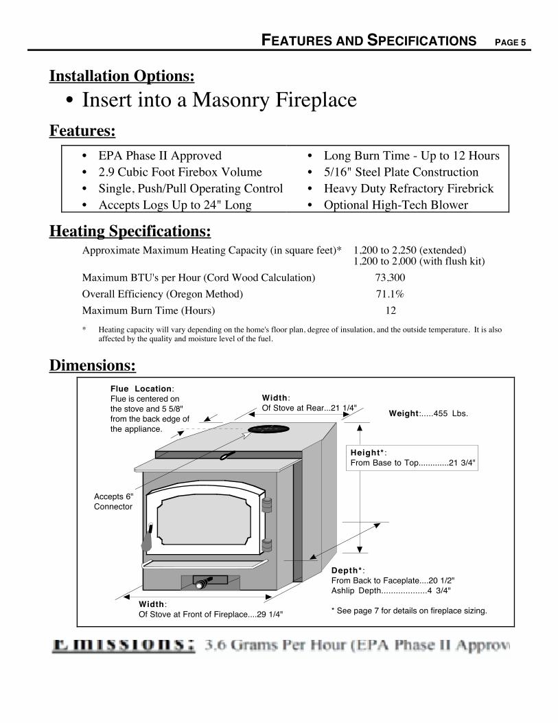
Installation Options:
¥ Insert into a Masonry FireplaceFeatures:
¥ EPA Phase II Approved¥ 2.9 Cubic Foot Firebox Volume¥ Single, Push/Pull Operating Control¥ Accepts Logs Up to 24" Long
¥ Long Burn Time - Up to 12 Hours¥ 5/16" Steel Plate Construction¥ Heavy Duty Refractory Firebrick¥ Optional High-Tech Blower
Heating Specifications:Approximate Maximum Heating Capacity (in square feet)* 1,200 to 2,250 (extended)
1,200 to 2,000 (with flush kit)
Maximum BTU's per Hour (Cord Wood Calculation) 73,300
Overall Efficiency (Oregon Method) 71.1%
Maximum Burn Time (Hours) 12
* Heating capacity will vary depending on the home's floor plan, degree of insulation, and the outside temperature. It is alsoaffected by the quality and moisture level of the fuel.
Dimensions:
Width:Of Stove at Rear...21 1/4"
Weight:.....455 Lbs.
Flue Location:Flue is centered on the stove and 5 5/8" from the back edge of the appliance.
Accepts 6" Connector
Width:Of Stove at Front of Fireplace....29 1/4"
Depth* :From Back to Faceplate....20 1/2"Ashlip Depth...................4 3/4"
* See page 7 for details on fireplace sizing.
Height* :From Base to Top.............21 3/4"
Emissions: 3.2 Grams Per Hour (EPA Phase II Approved) Ð Tests conducted by E.E.S.P.C. Lab.
PAGE 6 INSERT INSTALLATION
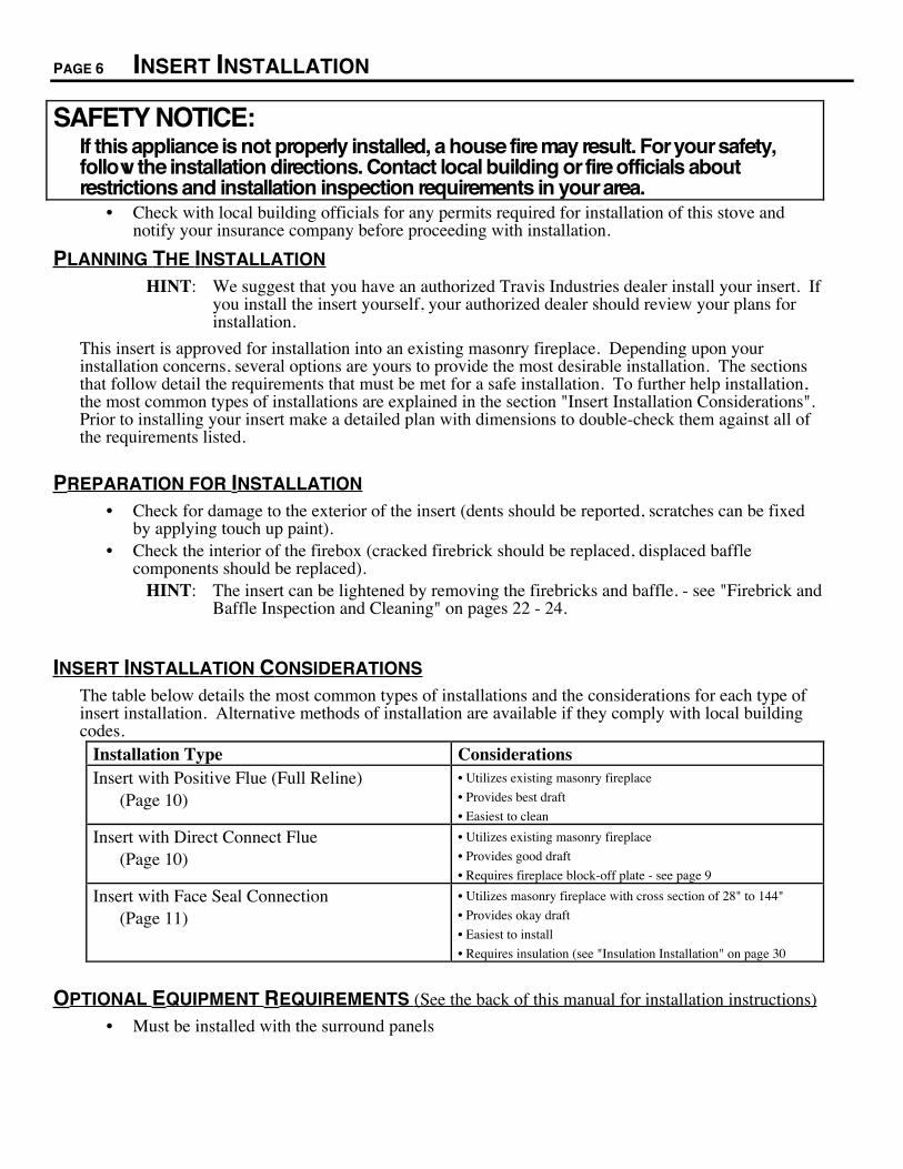
SAFETY NOTICE:If this appliance is not properly installed, a house fire may result. For your safety,follow the installation directions. Contact local building or fire officials aboutrestrictions and installation inspection requirements in your area.
¥ Check with local building officials for any permits required for installation of this stove andnotify your insurance company before proceeding with installation.
PLANNING THE INSTALLATION
HINT: We suggest that you have an authorized Travis Industries dealer install your insert. Ifyou install the insert yourself, your authorized dealer should review your plans forinstallation.
This insert is approved for installation into an existing masonry fireplace. Depending upon yourinstallation concerns, several options are yours to provide the most desirable installation. The sectionsthat follow detail the requirements that must be met for a safe installation. To further help installation,the most common types of installations are explained in the section "Insert Installation Considerations".Prior to installing your insert make a detailed plan with dimensions to double-check them against all ofthe requirements listed.
PREPARATION FOR INSTALLATION
¥ Check for damage to the exterior of the insert (dents should be reported, scratches can be fixedby applying touch up paint).
¥ Check the interior of the firebox (cracked firebrick should be replaced, displaced bafflecomponents should be replaced).
HINT: The insert can be lightened by removing the firebricks and baffle. - see "Firebrick andBaffle Inspection and Cleaning" on pages 22 - 24.
INSERT INSTALLATION CONSIDERATIONS
The table below details the most common types of installations and the considerations for each type ofinsert installation. Alternative methods of installation are available if they comply with local buildingcodes.
Installation Type ConsiderationsInsert with Positive Flue (Full Reline)
(Page 10)¥ Utilizes existing masonry fireplace
¥ Provides best draft
¥ Easiest to clean
Insert with Direct Connect Flue(Page 10)
¥ Utilizes existing masonry fireplace
¥ Provides good draft
¥ Requires fireplace block-off plate - see page 9
Insert with Face Seal Connection(Page 11)
¥ Utilizes masonry fireplace with cross section of 28" to 144"
¥ Provides okay draft
¥ Easiest to install
¥ Requires insulation (see "Insulation Installation" on page 30
OPTIONAL EQUIPMENT REQUIREMENTS (See the back of this manual for installation instructions)
¥ Must be installed with the surround panels
INSERT INSTALLATION (CONT.) PAGE 7
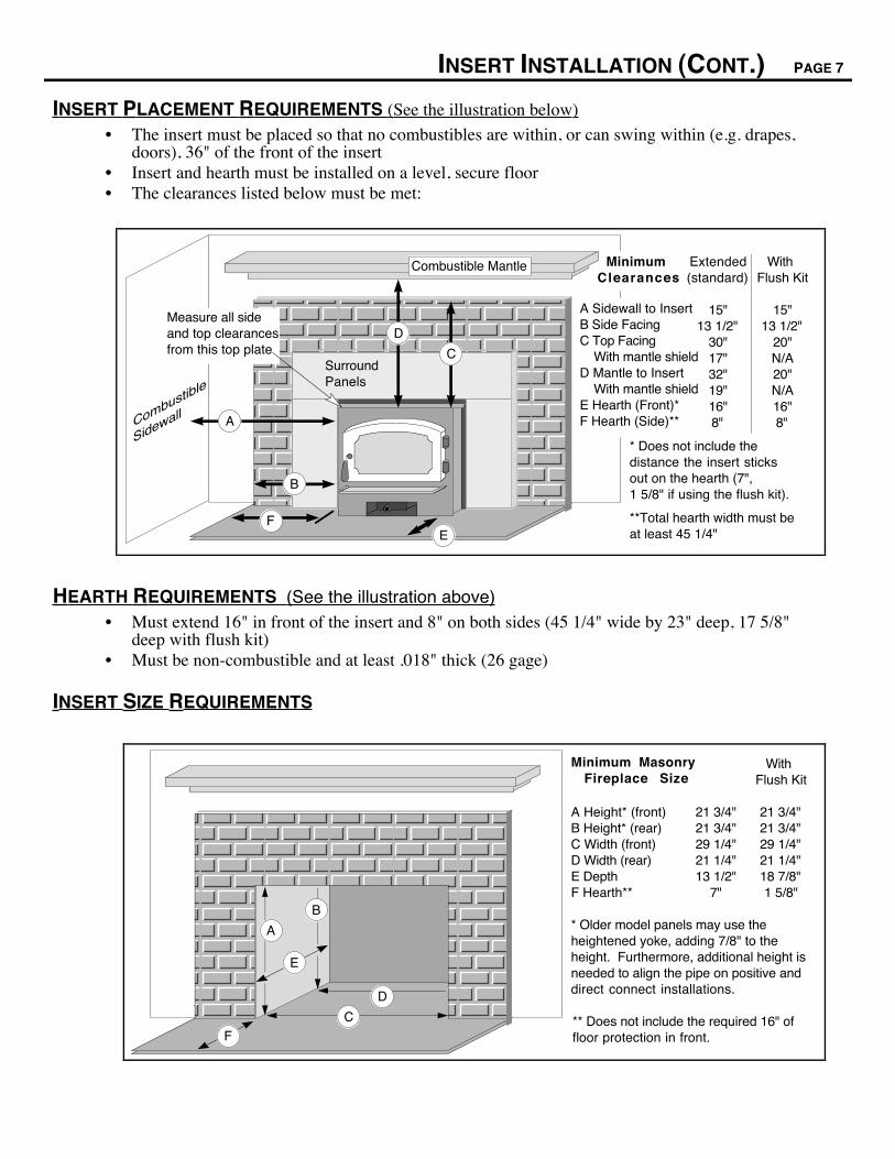
INSERT PLACEMENT REQUIREMENTS (See the illustration below)
¥ The insert must be placed so that no combustibles are within, or can swing within (e.g. drapes,doors), 36" of the front of the insert
¥ Insert and hearth must be installed on a level, secure floor¥ The clearances listed below must be met:
Combustible Mantle
Combustible
Sidewall
Surround Panels
A
B
* Does not include the distance the insert sticks out on the hearth (7",1 5/8" if using the flush kit).
**Total hearth width must be at least 45 1/4"E
D
C
F
Extended(standard)
15"13 1/2"
30"17"32"19"16"8"
Minimum Clearances
A Sidewall to InsertB Side FacingC Top Facing With mantle shieldD Mantle to Insert With mantle shieldE Hearth (Front)*F Hearth (Side)**
Measure all side and top clearances from this top plate
With Flush Kit
15"13 1/2"
20"N/A20"N/A16"8"
HEARTH REQUIREMENTS (See the illustration above)¥ Must extend 16" in front of the insert and 8" on both sides (45 1/4" wide by 23" deep, 17 5/8"
deep with flush kit)¥ Must be non-combustible and at least .018" thick (26 gage)
INSERT SIZE REQUIREMENTS
* Older model panels may use the heightened yoke, adding 7/8" to the height. Furthermore, additional height is needed to align the pipe on positive and direct connect installations.
Minimum Masonry Fireplace Size
E
D
C
A
B
F
A Height* (front)B Height* (rear)C Width (front)D Width (rear)E DepthF Hearth**
21 3/4"21 3/4"29 1/4"21 1/4"13 1/2"
7"
** Does not include the required 16" of floor protection in front.
With Flush Kit
21 3/4"21 3/4"29 1/4"21 1/4"18 7/8"1 5/8"
PAGE 8 INSERT INSTALLATION (CONT.)
MASONRY FIREPLACE REQUIREMENTS
¥ Chimney must have a clay tile liner or a stainless steel liner (positive connection)¥ Entire fireplace, including chimney, must be clean and undamaged. Any damage must be
repaired prior to installation of the insert¥ Chimney height: 15' minimum; 33' maximum.¥ Entire fireplace, including chimney, must meet local building requirements
LEVELING BOLT INSTALLATION
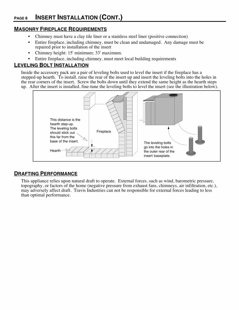
Inside the accessory pack are a pair of leveling bolts used to level the insert if the fireplace has astepped-up hearth. To install, raise the rear of the insert up and insert the leveling bolts into the holes inthe rear corners of the insert. Screw the bolts down until they extend the same height as the hearth stepsup. After the insert is installed, fine-tune the leveling bolts to level the insert (see the illustration below).
This distance is the hearth step-up. The leveling bolts should stick out this far from the base of the insert.
Fireplace
Hearth
The leveling bolts go into the holes in the outer rear of the insert baseplate.
DRAFTING PERFORMANCE
This appliance relies upon natural draft to operate. External forces, such as wind, barometric pressure,topography, or factors of the home (negative pressure from exhaust fans, chimneys, air infiltration, etc.),may adversely affect draft. Travis Industries can not be responsible for external forces leading to lessthan optimal performance.
INSERT INSTALLATION (CONT.) PAGE 9
BLOCK-OFF PLATE INSTALLATION
Whenever this appliance is installed with a direct connection a block-off plate, or other non-combustibleseal-off device (e.g. damper adapter), will need to be installed. This device is used to seal the chimney,insuring no smoke enters the home and providing the chimney system with a seal to provide greaterdraft. The directions below detail the steps for construction and installation of a block-off plate.
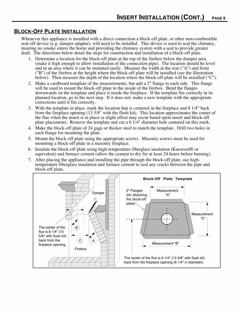
1. Determine a location for the block-off plate at the top of the firebox below the damper area(make it high enough to allow installation of the connection pipe). The location should be leveland in an area where it can be mounted easily. Measure the width at the rear ("A") and front("B") of the firebox at the height where the block-off plate will be installed (see the illustrationbelow). Then measure the depth of the location where the block-off plate will be installed ("C").
2. Make a cardboard template of the measurements, but add a 2" flange to each side. This flangewill be used to mount the block-off plate to the inside of the firebox. Bend the flangesdownwards on the template and place it inside the fireplace. If the template fits correctly in itsplanned location, go to the next step. If it does not, make a new template with the appropriatecorrections until it fits correctly.
3. With the template in place, mark the location that is centered in the fireplace and 8 1/4" backfrom the fireplace opening (13 5/8" with the flush kit). This location approximates the center ofthe flue when the insert is in place (a slight offset may occur based upon insert and block-offplate placement). Remove the template and cut a 6 1/4" diameter hole centered on this mark.
4. Make the block-off plate of 24 gage or thicker steel to match the template. Drill two holes ineach flange for mounting the plate.
5. Mount the block-off plate using the appropriate screws. Masonry screws must be used formounting a block-off plate in a masonry fireplace.
6. Insulate the block-off plate using high-temperature fiberglass insulation (KaowoolÒ orequivalent) and furnace cement (allow the cement to dry for at least 24 hours before burning).
7. After placing the appliance and installing the pipe through the block-off plate, use high-temperature fiberglass insulation and furnace cement to seal any cracks between the pipe andblock-off plate.
Firebox
AC
BThe center of the flue is 8 1/4" (13 5/8" with flush kit) back from the fireplace opening.
DamperMeasurement
"A"
Measurement "B"
2" Flanges (for attaching the block-off plate)
Measurement "C"
The center of the flue is 8 1/4" (13 5/8" with flush kit) back from the fireplace opening (6 1/4" in diameter).
Block-Off Plate Template

PAGE 10 INSERT INSTALLATION (CONT.)
INSERT WITHPOSITIVECONNECTION
NOTE:Most factory-built chimneymanufacturersmake stainlesssteel chimneyliners, eitherflexible orrigid. Thisprovides awide variety ofinstallationoptions. Makesure to followthemanufacturer'sinstructions forinstallationand support.
The liner must be stainless steel connector or flexible vent. Follow the liner manufacturer's insturctions for installation and support.
Remove damper or wire it open
Airtight Insulated Clean-Out
Combustible Mantle
NOTE: This installation may be used with a masonry fireplace only. The requirements in the section "Masonry Fireplace Requirements" must be fulfilled prior to installation.
Flue Liner
See the section "Insert Placement Requirements" for minimum clearances and hearth required.
Cap (prevents water from entering)
Install a non-combustible cover plate to prevent water from entering the chimney
Surround Panels
Notch the first connector to accommodate the bypass rod.
INSERT WITHDIRECTCONNECTION(MASONRYFIREPLACE)
NOTE:Directconnectionsrequireinstallation ofan airtightblock-off plateor damperadapter (seethe section"Block-offPlateConstruction"for details onconstructingand installing ablock-offplate).
Block-off plate or damper adapter
Remove damper or wire it open
Airtight Insulated Clean-Out
Stainless steel chimney connector must Extend 1' past the block-off plate or to the flue liner
Combustible Mantle
NOTE: This installation may be used with masonry fireplaces only. The requirements in the section "Masonry Fireplace Requirements must be fulfilled prior to installation.
Flue Liner
See the section "Insert Placement Requirements" for minimum clearances and hearth required.
Surround Panels
Notch the connector to accommodate the bypass rod.

INSERT INSTALLATION (CONT.) PAGE 11
INSERT WITHFACE SEALCONNECTION
NOTE:Face sealconnectionsrequireinstallation ofthe surroundpanels andinsulation (seethe section"SurroundPanelsInstallation"on page 29).
Remove damper or wire it open
Airtight Insulated Clean-Out
Combustible Mantle
NOTE: This installation may be used with a masonry fireplace only. The requirements in the section "Masonry Fireplace Requirements" must be fulfilled prior to installation.
Flue Liner
See the section "Insert Placement Requirements" for minimum clearances and hearth required.
Surround Panels with insulation (see "Surround Panels" installation instructions in the back of the manual)
NOTE: It is recommended your chimney have a minimum 28 and a maximum of 144 square inch cross-sectional area to use a face seal connection, otherwise your chimney maynot have sufficient draw for the fireplace insert to operate correctly.

PAGE 12 OPERATING YOUR APPLIANCE
SAFETY NOTICE:If this appliance is improperly operated , a house fire may result. For your safety,read the directions below and the Safety Precautions listed on pages 2 and 3 priorto operating this appliance.¥ If you have any questions regarding the operation of this appliance, contact your dealer.! Building a fire in disregard of the information provided in this section can cause permanent damage
to your appliance and void your warranty.! Never use gasoline, lantern fuel, kerosene, charcoal lighter fluid, or similar liquids to start of
"freshen up" a fire in this appliance. Keep these liquids well away from the appliance.! Keep furnishings and other combustible materials away from the appliance.
PAINT CURING
The paint on this stove cures under heat. Start a small fire and burn at a low rate for the first fire. Youwill notice fumes and smoke from the paint curing and oil burning off the steel. This is normal. Werecommend you open windows to vent the room.
ASH REMOVAL
Ashes should be placed in a metal container with a tight fitting lid. The closed container of ashes shouldbe placed on a noncombustible floor or on the ground, away from all combustible materials, pendingfinal disposal. Ashes should be retained in the closed container until all cinders have thoroughly cooled.
LOCATION OF CONTROLS
Slide out to close down the amount of air into the firebox, for a slower rate of burn
DOOR HANDLE
AIR CONTROL
Slide in to allow more air into the firebox, for a faster rate of burn
1.
2.
To open, turn the handle counter-clockwise and swing the door forward.
BYPASS CONTROL
Pull the bypass out for loading & starting. Push the bypass in during burning.
¥ Do not open the door when the air control is closed. This may result in a sudden flash of flames asthe fire ignites with oxygen. However, this appliance has been designed to reduce this possibility.
¥ The controls become hot during operation Ð use a glove or other device if necessary.¥ Open the door for refueling only, do not operate with the door open or removed.
Approximate Air Control Settings: Overnight Burn ..................... Fully out to 9/32" openMedium Burn ........................ 9/32" open to 5/16" openMedium High Burn ............... 5/16" open to 7/16" openHigh Burn.............................. 7/16" open to pushed fully in
OPERATING YOUR APPLIANCE (CONTINUED) PAGE 13
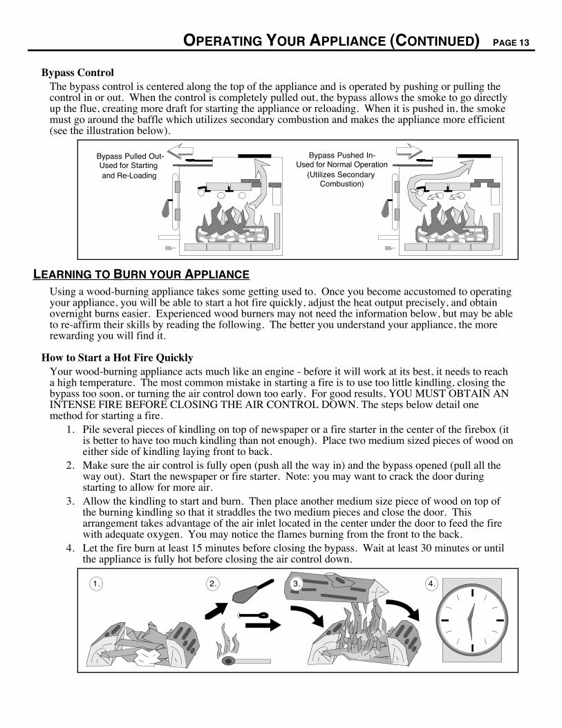
Bypass ControlThe bypass control is centered along the top of the appliance and is operated by pushing or pulling thecontrol in or out. When the control is completely pulled out, the bypass allows the smoke to go directlyup the flue, creating more draft for starting the appliance or reloading. When it is pushed in, the smokemust go around the baffle which utilizes secondary combustion and makes the appliance more efficient(see the illustration below).
Bypass Pushed In-Used for Normal Operation
(Utilizes Secondary Combustion)
Bypass Pulled Out-Used for Starting and Re-Loading
LEARNING TO BURN YOUR APPLIANCE
Using a wood-burning appliance takes some getting used to. Once you become accustomed to operatingyour appliance, you will be able to start a hot fire quickly, adjust the heat output precisely, and obtainovernight burns easier. Experienced wood burners may not need the information below, but may be ableto re-affirm their skills by reading the following. The better you understand your appliance, the morerewarding you will find it.
How to Start a Hot Fire QuicklyYour wood-burning appliance acts much like an engine - before it will work at its best, it needs to reacha high temperature. The most common mistake in starting a fire is to use too little kindling, closing thebypass too soon, or turning the air control down too early. For good results, YOU MUST OBTAIN ANINTENSE FIRE BEFORE CLOSING THE AIR CONTROL DOWN. The steps below detail onemethod for starting a fire.
1. Pile several pieces of kindling on top of newspaper or a fire starter in the center of the firebox (itis better to have too much kindling than not enough). Place two medium sized pieces of wood oneither side of kindling laying front to back.
2. Make sure the air control is fully open (push all the way in) and the bypass opened (pull all theway out). Start the newspaper or fire starter. Note: you may want to crack the door duringstarting to allow for more air.
3. Allow the kindling to start and burn. Then place another medium size piece of wood on top ofthe burning kindling so that it straddles the two medium pieces and close the door. Thisarrangement takes advantage of the air inlet located in the center under the door to feed the firewith adequate oxygen. You may notice the flames burning from the front to the back.
4. Let the fire burn at least 15 minutes before closing the bypass. Wait at least 30 minutes or untilthe appliance is fully hot before closing the air control down.
4.1. 2. 3.
PAGE 14 OPERATING YOUR APPLIANCE(CONTINUED)
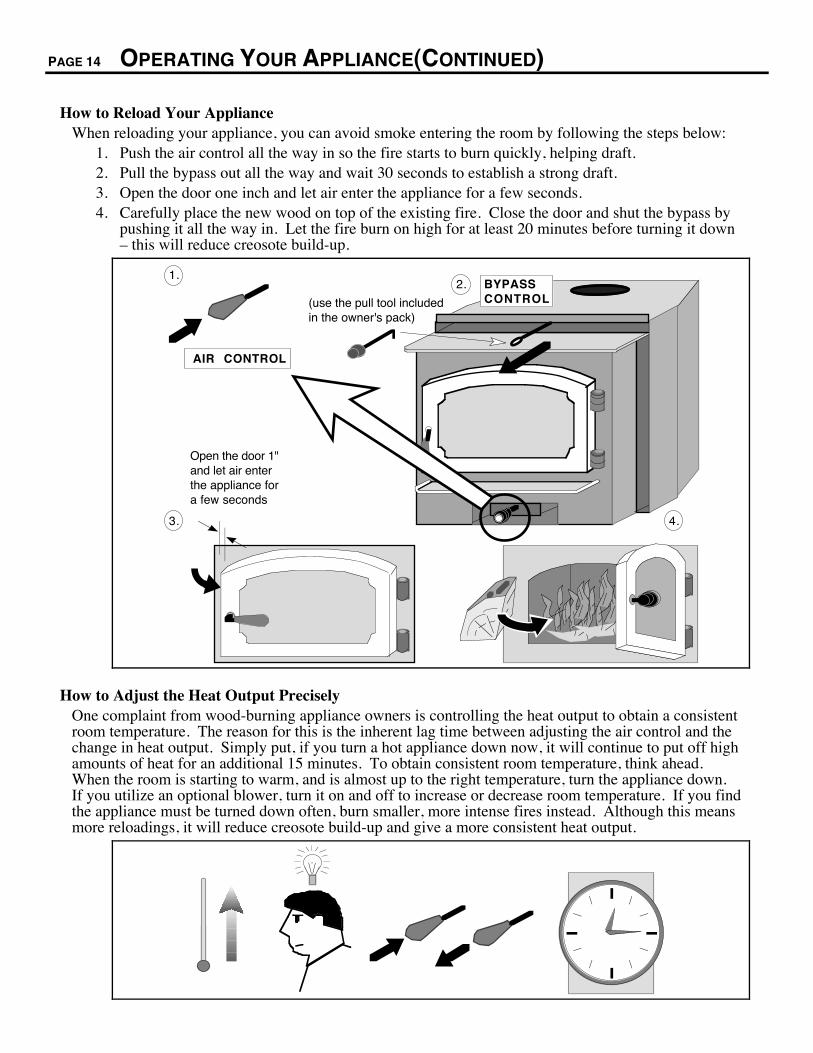
How to Reload Your ApplianceWhen reloading your appliance, you can avoid smoke entering the room by following the steps below:
1. Push the air control all the way in so the fire starts to burn quickly, helping draft.2. Pull the bypass out all the way and wait 30 seconds to establish a strong draft.3. Open the door one inch and let air enter the appliance for a few seconds.4. Carefully place the new wood on top of the existing fire. Close the door and shut the bypass by
pushing it all the way in. Let the fire burn on high for at least 20 minutes before turning it downÐ this will reduce creosote build-up.
AIR CONTROL
1.
Open the door 1" and let air enter the appliance for a few seconds
4.3.
BYPASS CONTROL
2.
(use the pull tool included in the owner's pack)
How to Adjust the Heat Output PreciselyOne complaint from wood-burning appliance owners is controlling the heat output to obtain a consistentroom temperature. The reason for this is the inherent lag time between adjusting the air control and thechange in heat output. Simply put, if you turn a hot appliance down now, it will continue to put off highamounts of heat for an additional 15 minutes. To obtain consistent room temperature, think ahead.When the room is starting to warm, and is almost up to the right temperature, turn the appliance down.If you utilize an optional blower, turn it on and off to increase or decrease room temperature. If you findthe appliance must be turned down often, burn smaller, more intense fires instead. Although this meansmore reloadings, it will reduce creosote build-up and give a more consistent heat output.
OPERATING YOUR APPLIANCE (CONTINUED) PAGE 15
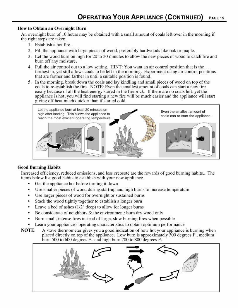
How to Obtain an Overnight BurnAn overnight burn of 10 hours may be obtained with a small amount of coals left over in the morning ifthe right steps are taken.
1. Establish a hot fire.2. Fill the appliance with large pieces of wood, preferably hardwoods like oak or maple.3. Let the wood burn on high for 20 to 30 minutes to allow the new pieces of wood to catch fire and
burn off any moisture.4. Pull the air control out to a low setting. HINT: You want an air control position that is the
farthest in, yet still allows coals to be left in the morning. Experiment using air control positionsthat are farther and farther in until a suitable position is found.
5. In the morning, break down the coals and lay kindling and small pieces of wood on top of thecoals to re-establish the fire. NOTE: Even the smallest amount of coals can start a new fireeasily because of all the heat energy stored in the firebrick. If there are no coals left, yet theappliance is hot, you will find starting a new fire will be much easier and the appliance will startgiving off heat much quicker than if started cold.
Let the appliance burn at least 20 minutes on high after loading. This allows the appliance to reach the most efficient operating temperature.
Even the smallest amount of coals can re-start the appliance.
Good Burning HabitsIncreased efficiency, reduced emissions, and less creosote are the rewards of good burning habits.. Theitems below list good habits to establish with your new appliance.
¥ Get the appliance hot before turning it down¥ Use smaller pieces of wood during start-up and high burns to increase temperature¥ Use larger pieces of wood for overnight or sustained burns¥ Stack the wood tightly together to establish a longer burn¥ Leave a bed of ashes (1/2" deep) to allow for longer burns¥ Be considerate of neighbors & the environment: burn dry wood only¥ Burn small, intense fires instead of large, slow burning fires when possible¥ Learn your appliance's operating characteristics to obtain optimum performance
NOTE: A stove thermometer gives you a good indication of how hot your appliance is burning whenplaced directly on top of the appliance. Low burn is approximately 300 degrees F., mediumburn 500 to 600 degrees F., and high burn 700 to 800 degrees F.
PAGE 16 OPERATING YOUR APPLIANCE(CONTINUED)
BLOWER OPERATION
The optional blower assists the convection chamber in distributing heat to your home. The directionsbelow detail operation.
Automatic ControlThe optional blower has a temperature-sensing device to automatically enable the blower once theappliance reaches a hot temperature. It also shuts the blower off once the appliance has cooled.
When to turn the blower onThe blower should be left on the off position for the first 30 minutes of starting the appliance.
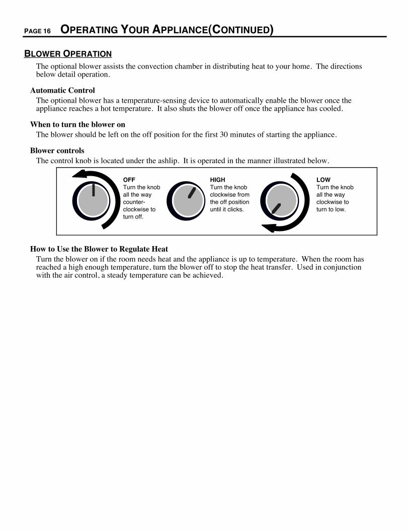
Blower controlsThe control knob is located under the ashlip. It is operated in the manner illustrated below.
OFF Turn the knob all the way counter- clockwise to turn off.
HIGH Turn the knob clockwise from the off position until it clicks.
LOW Turn the knob all the way clockwise to turn to low.
How to Use the Blower to Regulate HeatTurn the blower on if the room needs heat and the appliance is up to temperature. When the room hasreached a high enough temperature, turn the blower off to stop the heat transfer. Used in conjunctionwith the air control, a steady temperature can be achieved.
OPERATING YOUR APPLIANCE (CONTINUED) PAGE 17
A WORD ABOUT WOOD
This appliance is designed to burn natural cord wood with high efficiencies and low emissions. Withproperly dried wood, you will fully realize the heating and clean-burning potential of our high-technology appliance. With poor wood, this high-technology appliance will become much less efficientand produce more emissions. Read on to find out more about the type of fuel you should use.
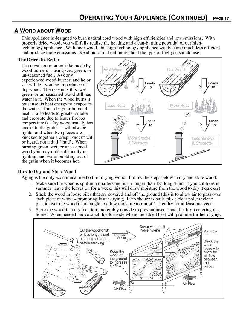
The Drier the BetterThe most common mistake made bywood-burners is using wet, green, orun-seasoned fuel. Ask anyexperienced wood-burner, and he orshe will tell you the importance ofdry wood. The reason is this: wet,green, or un-seasoned wood still haswater in it. When the wood burns itmust use its heat energy to evaporatethe water. This robs your home ofheat (it also leads to greater smokeand creosote due to lesser fireboxtemperatures). Dry wood usually hascracks in the grain. It will also belighter and when two pieces areknocked together a crisp "knock" willbe heard, not a dull "thud". Whenburning green, wet, or unseasonedwood you may notice difficulty inlighting, and water bubbling out ofthe grain when it becomes hot.
More Smoke& Creosote
Less Smoke& Creosote
More HeatLess Heat
Wet Wood
LeadsTo
LeadsTo
LeadsTo
LeadsTo
Dry Wood
How to Dry and Store WoodAging is the only economical method for drying wood. Follow the steps below to dry and store wood:
1. Make sure the wood is split into quarters and is no longer than 18" long (Hint: if you cut trees insummer, leave the leaves on for a week, this will draw moisture from the wood to dry it quicker).
2. Stack the wood in loose piles that are covered and off the ground (this is to allow air to pass overeach piece of wood Ð promoting faster drying) If no shelter is built, place clear polyethyleneplastic over the wood (at an angle to allow moisture to run off). Let dry for at least one year.
3. Store the wood in a dry location, preferably outside to prevent insects and dirt from entering thehome. When needed, move small loads inside where the added heat will promote further drying.
Keep thewood offthe groundto increaseair flow
Cover with 4 milPolyethylene Air Flow
Air Flow
Air Flow
PrevailingWinds
Stack thewoodloosely toallow forair flowbetweenthepieces
Cut the wood to 18"or less lengths andchop into quartersbefore stacking
PAGE 18 OPERATING YOUR APPLIANCE(CONTINUED)
A WORD ABOUT WOOD (CONTINUED)
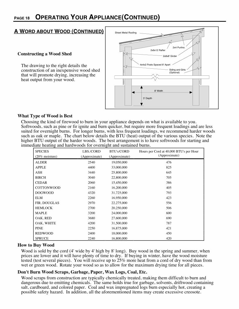
Constructing a Wood Shed
The drawing to the right details theconstruction of an inexpensive wood shedthat will promote drying, increasing theheat output from your wood.
3' Depth
8' Width
Sheet Metal Roofing
2x4 Purlins
4x4x2 Posts Spaced 8' Apart
2x6x12 Rafter
Siding and Girts (Optional)
2x8x8' Girder
What Type of Wood is BestChoosing the kind of firewood to burn in your appliance depends on what is available to you.Softwoods, such as pine or fir ignite and burn quicker, but require more frequent loadings and are lesssuited for overnight burns. For longer burns, with less frequent loadings, we recommend harder woodssuch as oak or maple. The chart below details the BTU (heat) output of the various species. Note thehigher BTU output of the harder woods. The best arrangement is to have softwoods for starting andimmediate heating and hardwoods for overnight and sustained burns.
SPECIES
(20% moisture)
LBS./CORD
(Approximate)
BTU's/CORD
(Approximate)
Hours per Cord at 40,000 BTU's per Hour(Approximate)
ALDER 2540 19,050,000 476
APPLE 4400 33,000,000 825
ASH 3440 25,800,000 645
BIRCH 3040 22,800,000 705
CEDAR 2060 15,450,000 386
COTTONWOOD 2160 16,200,000 405
DOGWOOD 4320 31,725,000 793
ELM 2260 16,950,000 423
FIR, DOUGLAS 2970 22,275,000 556
HEMLOCK 2700 20,250,000 506
MAPLE 3200 24,000,000 600
OAK, RED 3680 27,600,000 690
OAK, WHITE 4200 31,500,000 787
PINE 2250 16,875,000 421
REDWOOD 2400 18,000,000 450
SPRUCE 2240 16,800,000 420
How to Buy WoodWood is sold by the cord (4' wide by 4' high by 8' long). Buy wood in the spring and summer, whenprices are lower and it will have plenty of time to dry. If buying in winter, have the wood moisturetested (test several pieces). You will receive up to 25% more heat from a cord of dry wood than fromwet or green wood. Rotate your wood so as to allow for the maximum drying time for all pieces.
Don't Burn Wood Scraps, Garbage, Paper, Wax Logs, Coal, Etc.Wood scraps from construction are typically chemically treated, making them difficult to burn anddangerous due to emitting chemicals. The same holds true for garbage, solvents, driftwood containingsalt, cardboard, and colored paper. Coal and wax impregnated logs burn especially hot, creating apossible safety hazard. In addition, all the aforementioned items may create excessive creosote.
MAINTAINING YOUR APPLIANCE PAGE 19
MAINTENANCE SCHEDULEYour appliance requires periodic maintenance to work correctly. The steps involved with maintenanceare usually quick and easy. Look through this maintenance schedule and plan accordingly.
WARNING: Failure to properly maintain and inspect your appliance may reduce theperformance and life of the appliance, void your warranty, and create a fire hazard.
PERIODIC MAINTENANCE (every week when appliance is in use):¥ Remove ash from the firebox (if necessary)¥ Clean the viewing glass (if necessary)¥ Clean the brass (if necessary)¥ Check for creosote buildup in the chimney and connector
BI-MONTHLY MAINTENANCE (every two months during the heating season):¥ Door and glass inspection¥ Lubricate the door hinge
YEARLY MAINTENANCE (before every heating season):¥ Touch-up paint¥ Blower cleaning¥ Firebrick and baffle inspection and cleaning
REMOVE ASH FROM THE FIREBOX (IF NECESSARY)At least once a week while the appliance is in use, check the level of ash on the floor of the firebox. If1" or more of ash has accumulated, let the appliance cool and place the excess ash into an airtightcontainer away from any structure. After the ash is fully extinguished it may be disposed. A 1/2" to 1"bed of ash is desirable, for it allows the appliance to burn at a slightly lower speed.
WARNING: Ashes removed from the appliance must be stored in an airtight container awayfrom any structure until fully extinguished before disposing.
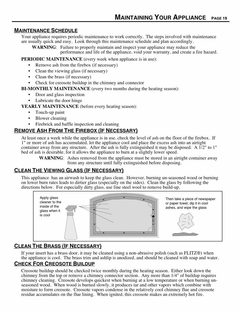
CLEAN THE VIEWING GLASS (IF NECESSARY)This appliance has an airwash to keep the glass clean. However, burning un-seasoned wood or burningon lower burn rates leads to dirtier glass (especially on the sides). Clean the glass by following thedirections below. For especially dirty glass, use fine steel wool to remove build-up.
Then take a piece of newspaper or paper towel, dip it in cool ashes, and wipe the glass
Apply glass cleaner to the inside of the glass when it is cool
CLEAN THE BRASS (IF NECESSARY)If your insert has a brass door, it may be cleaned using a non-abrasive polish (such as FLITZÒ) whenthe appliance is cool. The brass trim and ashlip is anodized, and should be cleaned with soap and water.
CHECK FOR CREOSOTE BUILDUPCreosote buildup should be checked twice monthly during the heating season. Either look down thechimney from the top or remove a chimney connector section. Any more than 1/4" of buildup requireschimney cleaning. Creosote develops quickest when burning at a low temperature or when burning un-seasoned wood. When wood is burned slowly, it produces tar and other vapors which combine withmoisture to form creosote. Creosote vapors condense in the relatively cool chimney flue and creosoteresidue accumulates on the flue lining. When ignited, this creosote makes an extremely hot fire.
PAGE 20 MAINTAINING YOUR APPLIANCE (CONTINUED)
DOOR AND GLASS INSPECTION
The door must seal air-tight for the appliance to work correctly. Check the two items below and followthe appropriate remedy to fix any problems.
¥ Check the door cam operation. When closed, the door cam should pull the door against the faceof the appliance, but not be so tight as to not allow the handle to point downwards. If theoperation is not correct, see the section "Adjusting the Door Cam" below.
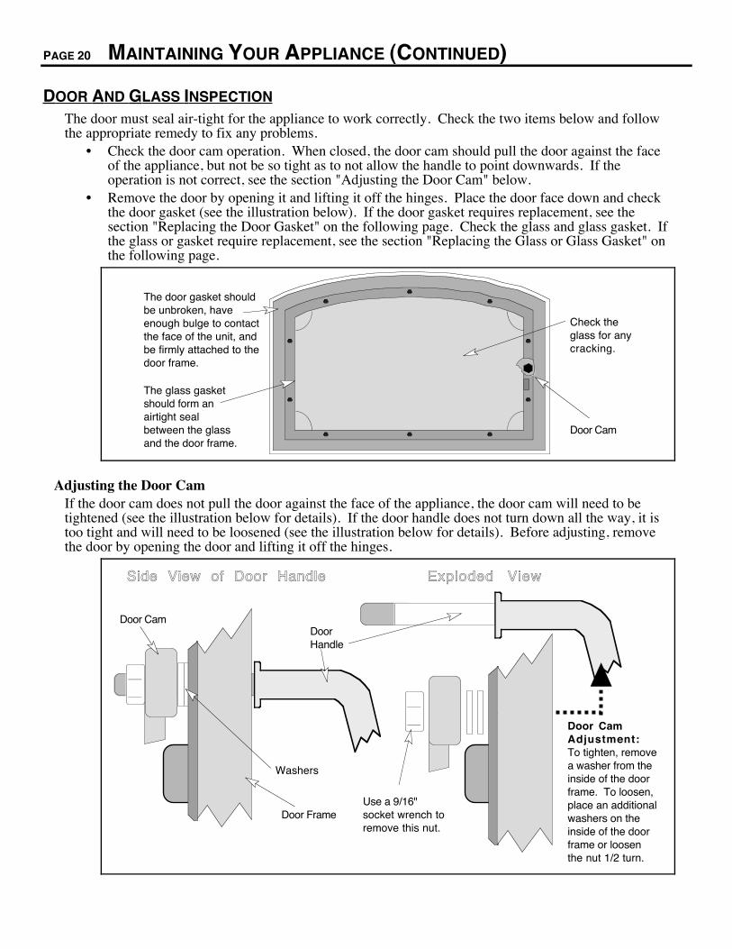
¥ Remove the door by opening it and lifting it off the hinges. Place the door face down and checkthe door gasket (see the illustration below). If the door gasket requires replacement, see thesection "Replacing the Door Gasket" on the following page. Check the glass and glass gasket. Ifthe glass or gasket require replacement, see the section "Replacing the Glass or Glass Gasket" onthe following page.
The door gasket should be unbroken, have enough bulge to contact the face of the unit, and be firmly attached to the door frame.
The glass gasket should form an airtight seal between the glass and the door frame.
Door Cam
Check the glass for any cracking.
Adjusting the Door CamIf the door cam does not pull the door against the face of the appliance, the door cam will need to betightened (see the illustration below for details). If the door handle does not turn down all the way, it istoo tight and will need to be loosened (see the illustration below for details). Before adjusting, removethe door by opening the door and lifting it off the hinges.
Door CamDoor Handle
Washers
Door FrameUse a 9/16" socket wrench to remove this nut.
Side View of Door Handle
Door Cam Adjustment:To tighten, remove a washer from the inside of the door frame. To loosen, place an additional washers on the inside of the door frame or loosen the nut 1/2 turn.
Exploded View
MAINTAINING YOUR APPLIANCE (CONTINUED) PAGE 21
Replacing the Door GasketRemove the door by opening it and lifting it off the hinges. Remove the old gasket by stripping it awaywith a screwdriver or other tool (see the illustration below). Apply a line of gasket cement (availablefrom your dealer) in the groove that follows the perimeter of the door. Insert the gasket into the groove.Do not stretch the gasket as you place it into the groove. Cut off any excess gasket when done. Allow 2hours for the cement to dry. When re-installing the door, the gasket may need to be flattened byrepeatedly opening and closing the door.
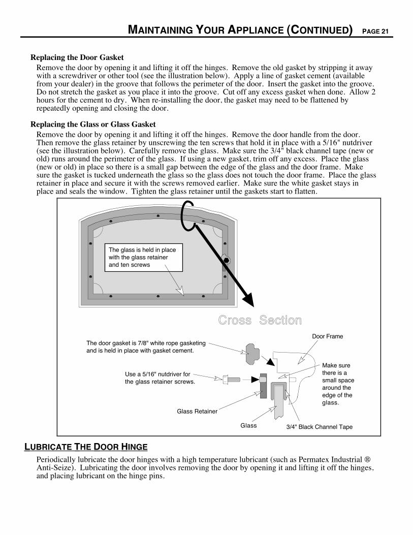
Replacing the Glass or Glass GasketRemove the door by opening it and lifting it off the hinges. Remove the door handle from the door.Then remove the glass retainer by unscrewing the ten screws that hold it in place with a 5/16" nutdriver(see the illustration below). Carefully remove the glass. Make sure the 3/4" black channel tape (new orold) runs around the perimeter of the glass. If using a new gasket, trim off any excess. Place the glass(new or old) in place so there is a small gap between the edge of the glass and the door frame. Makesure the gasket is tucked underneath the glass so the glass does not touch the door frame. Place the glassretainer in place and secure it with the screws removed earlier. Make sure the white gasket stays inplace and seals the window. Tighten the glass retainer until the gaskets start to flatten.
Use a 5/16" nutdriver for the glass retainer screws.
The door gasket is 7/8" white rope gasketing and is held in place with gasket cement.
Cross SectionDoor Frame
Glass
Glass Retainer
3/4" Black Channel Tape
The glass is held in place with the glass retainer and ten screws
Make sure there is a small space around the edge of the glass.
LUBRICATE THE DOOR HINGE
Periodically lubricate the door hinges with a high temperature lubricant (such as Permatex Industrial ÒAnti-Seize). Lubricating the door involves removing the door by opening it and lifting it off the hinges,and placing lubricant on the hinge pins.
PAGE 22 MAINTAINING YOUR APPLIANCE (CONTINUED)
TOUCH-UP PAINT
Included with the owner's pack of this appliance is a can ofStove-BriteÒ paint. To touch up nicks or dulled paint, applythe paint while the appliance is cool. Use 120 grit sandpaper(clean with water and dry with a piece of cloth) if the surfacerequires smoothing. Wait at least one hour before starting theappliance. The touched up area will appear darker than thesurrounding paint until it cures from heat. Curing will give offsome fumes while curing Ð open windows to ventilate thefumes.
Touch-Up P a i n t
BLOWER CLEANING
The blower for this appliance will gather dust as it circulates air. Before cleaning, remove the blowerfrom the appliance (see "Blower Installation" on page 8). Remove all dust and debris from the blowergrill and around the interior of the blower.
FIREBRICK AND BAFFLE INSPECTION AND CLEANING
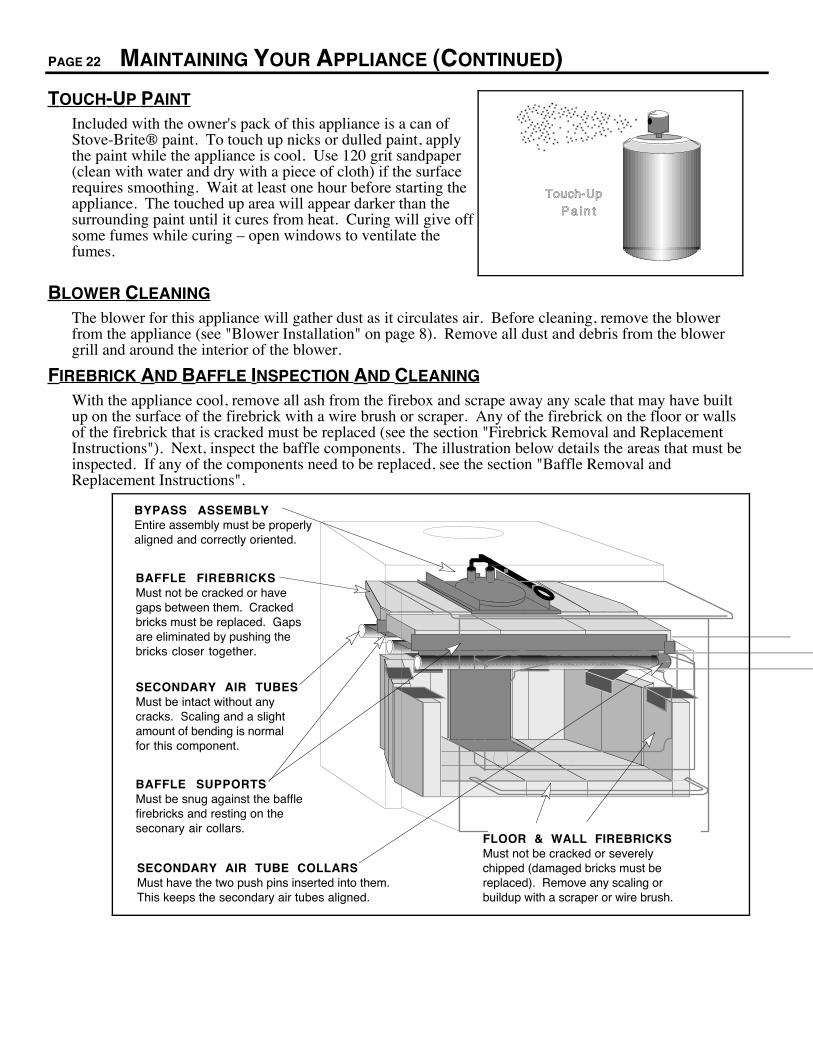
With the appliance cool, remove all ash from the firebox and scrape away any scale that may have builtup on the surface of the firebrick with a wire brush or scraper. Any of the firebrick on the floor or wallsof the firebrick that is cracked must be replaced (see the section "Firebrick Removal and ReplacementInstructions"). Next, inspect the baffle components. The illustration below details the areas that must beinspected. If any of the components need to be replaced, see the section "Baffle Removal andReplacement Instructions".
BAFFLE FIREBRICKSMust not be cracked or have gaps between them. Cracked bricks must be replaced. Gaps are eliminated by pushing the bricks closer together.
SECONDARY AIR TUBESMust be intact without any cracks. Scaling and a slight amount of bending is normal for this component.
BAFFLE SUPPORTSMust be snug against the baffle firebricks and resting on the seconary air collars.
SECONDARY AIR TUBE COLLARSMust have the two push pins inserted into them. This keeps the secondary air tubes aligned.
BYPASS ASSEMBLYEntire assembly must be properly aligned and correctly oriented.
FLOOR & WALL FIREBRICKSMust not be cracked or severely chipped (damaged bricks must be replaced). Remove any scaling or buildup with a scraper or wire brush.
MAINTAINING YOUR APPLIANCE (CONTINUED) PAGE 23
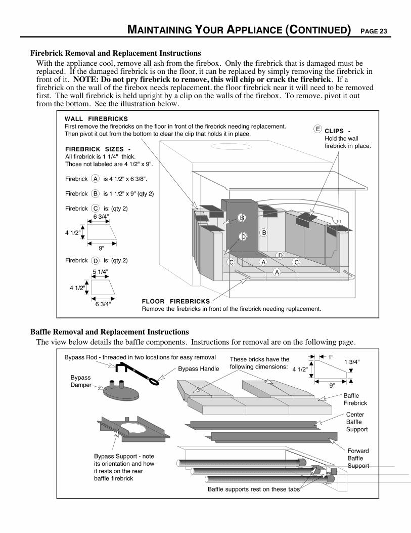
Firebrick Removal and Replacement InstructionsWith the appliance cool, remove all ash from the firebox. Only the firebrick that is damaged must bereplaced. If the damaged firebrick is on the floor, it can be replaced by simply removing the firebrick infront of it. NOTE: Do not pry firebrick to remove, this will chip or crack the firebrick. If afirebrick on the wall of the firebox needs replacement, the floor firebrick near it will need to be removedfirst. The wall firebrick is held upright by a clip on the walls of the firebox. To remove, pivot it outfrom the bottom. See the illustration below.
WALL FIREBRICKSFirst remove the firebricks on the floor in front of the firebrick needing replacement. Then pivot it out from the bottom to clear the clip that holds it in place.
FLOOR FIREBRICKSRemove the firebricks in front of the firebrick needing replacement.
CLIPS -Hold the wall firebrick in place.FIREBRICK SIZES -
All firebrick is 1 1/4" thick. Those not labeled are 4 1/2" x 9". Firebrick is 4 1/2" x 6 3/8".
Firebrick is 1 1/2" x 9" (qty 2)
Firebrick is: (qty 2)
Firebrick is: (qty 2)
A
E
B
D
C
4 1/2"
9"
6 3/4"
4 1/2"
6 3/4"
5 1/4"
B
A
CD
C A
D
B
Baffle Removal and Replacement InstructionsThe view below details the baffle components. Instructions for removal are on the following page.
Bypass Damper
Bypass Handle
Bypass Rod - threaded in two locations for easy removal
Bypass Support - note its orientation and how it rests on the rear baffle firebrick
Forward Baffle Support
Baffle supports rest on these tabs
Baffle Firebrick
Center Baffle Support
4 1/2"
1"
9"
1 3/4"These bricks have the following dimensions:
PAGE 24 MAINTAINING YOUR APPLIANCE (CONTINUED)
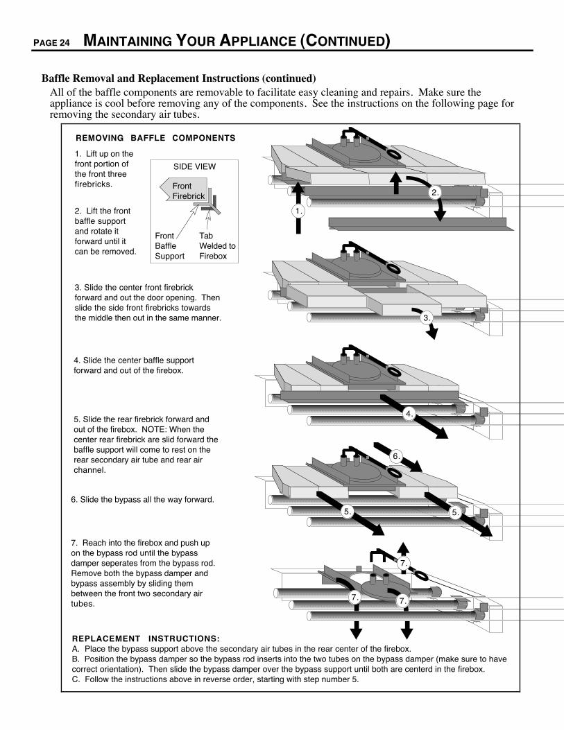
Baffle Removal and Replacement Instructions (continued)All of the baffle components are removable to facilitate easy cleaning and repairs. Make sure theappliance is cool before removing any of the components. See the instructions on the following page forremoving the secondary air tubes.
REMOVING BAFFLE COMPONENTS
1. Lift up on the front portion of the front three firebricks.
3. Slide the center front firebrick forward and out the door opening. Then slide the side front firebricks towards the middle then out in the same manner.
2. Lift the front baffle support and rotate it forward until it can be removed.
4. Slide the center baffle support forward and out of the firebox.
5. Slide the rear firebrick forward and out of the firebox. NOTE: When the center rear firebrick are slid forward the baffle support will come to rest on the rear secondary air tube and rear air channel.
6. Slide the bypass all the way forward.
7. Reach into the firebox and push up on the bypass rod until the bypass damper seperates from the bypass rod. Remove both the bypass damper and bypass assembly by sliding them between the front two secondary air tubes.
REPLACEMENT INSTRUCTIONS:A. Place the bypass support above the secondary air tubes in the rear center of the firebox.B. Position the bypass damper so the bypass rod inserts into the two tubes on the bypass damper (make sure to have correct orientation). Then slide the bypass damper over the bypass support until both are centerd in the firebox.C. Follow the instructions above in reverse order, starting with step number 5.
1.
2.
5.
Tab Welded to Firebox
Front Baffle Support
Front Firebrick
SIDE VIEW
3.
4.
5.
6.
7.
7. 7.
MAINTAINING YOUR APPLIANCE (CONTINUED) PAGE 25
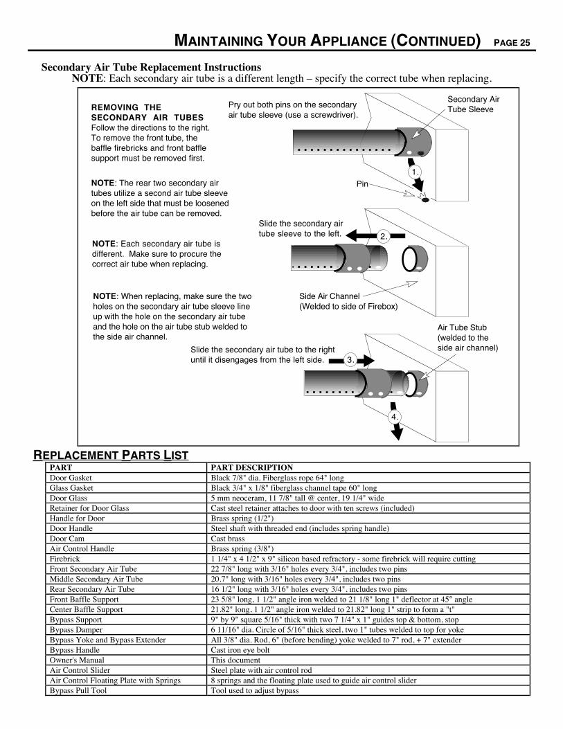
Secondary Air Tube Replacement InstructionsNOTE: Each secondary air tube is a different length Ð specify the correct tube when replacing.
NOTE: Each secondary air tube is different. Make sure to procure the correct air tube when replacing.
Secondary Air Tube SleevePry out both pins on the secondary
air tube sleeve (use a screwdriver).
1.Pin
Slide the secondary air tube sleeve to the left. 2.
Side Air Channel (Welded to side of Firebox)
NOTE: When replacing, make sure the two holes on the secondary air tube sleeve line up with the hole on the secondary air tube and the hole on the air tube stub welded to the side air channel.
Slide the secondary air tube to the right until it disengages from the left side. 3.
Air Tube Stub (welded to the side air channel)
4.
REMOVING THE SECONDARY AIR TUBESFollow the directions to the right. To remove the front tube, the baffle firebricks and front baffle support must be removed first.
NOTE: The rear two secondary air tubes utilize a second air tube sleeve on the left side that must be loosened before the air tube can be removed.
REPLACEMENT PARTS LISTPART PART DESCRIPTIONDoor Gasket Black 7/8" dia. Fiberglass rope 64" longGlass Gasket Black 3/4" x 1/8" fiberglass channel tape 60" longDoor Glass 5 mm neoceram, 11 7/8" tall @ center, 19 1/4" wideRetainer for Door Glass Cast steel retainer attaches to door with ten screws (included)Handle for Door Brass spring (1/2")Door Handle Steel shaft with threaded end (includes spring handle)Door Cam Cast brassAir Control Handle Brass spring (3/8")Firebrick 1 1/4" x 4 1/2" x 9" silicon based refractory - some firebrick will require cuttingFront Secondary Air Tube 22 7/8" long with 3/16" holes every 3/4", includes two pinsMiddle Secondary Air Tube 20.7" long with 3/16" holes every 3/4", includes two pinsRear Secondary Air Tube 16 1/2" long with 3/16" holes every 3/4", includes two pinsFront Baffle Support 23 5/8" long, 1 1/2" angle iron welded to 21 1/8" long 1" deflector at 45° angleCenter Baffle Support 21.82" long, 1 1/2" angle iron welded to 21.82" long 1" strip to form a "t"Bypass Support 9" by 9" square 5/16" thick with two 7 1/4" x 1" guides top & bottom, stopBypass Damper 6 11/16" dia. Circle of 5/16" thick steel, two 1" tubes welded to top for yokeBypass Yoke and Bypass Extender All 3/8" dia. Rod, 6" (before bending) yoke welded to 7" rod, + 7" extenderBypass Handle Cast iron eye boltOwner's Manual This documentAir Control Slider Steel plate with air control rodAir Control Floating Plate with Springs 8 springs and the floating plate used to guide air control sliderBypass Pull Tool Tool used to adjust bypass
PAGE 26 TROUBLESHOOTING
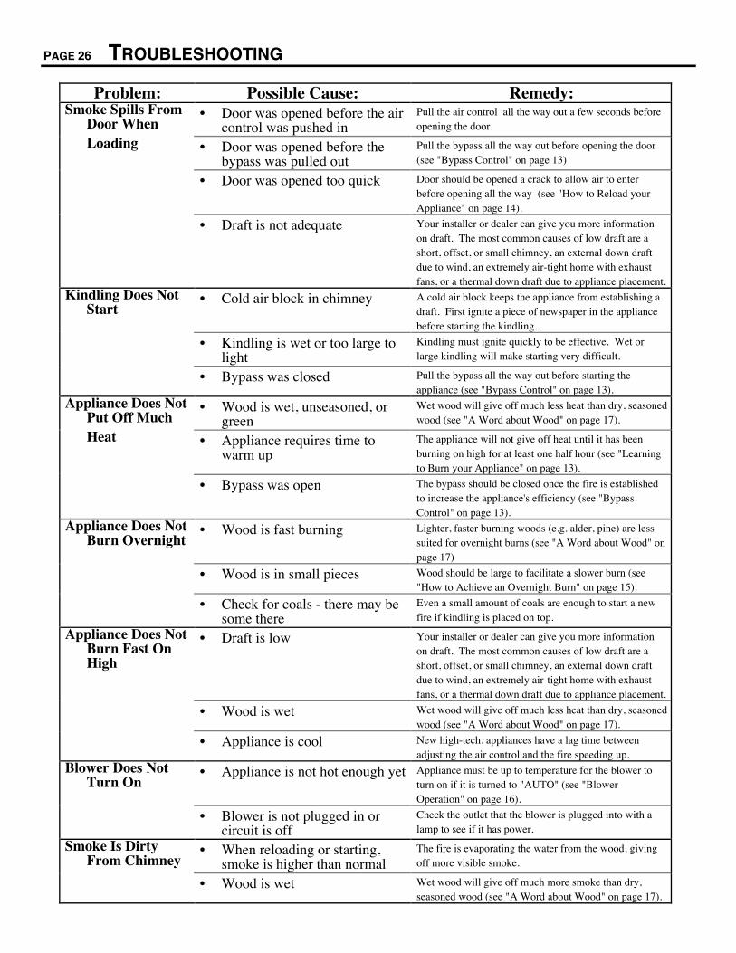
Problem: Possible Cause: Remedy:Smoke Spills From
Door When¥ Door was opened before the air
control was pushed inPull the air control all the way out a few seconds beforeopening the door.
Loading ¥ Door was opened before thebypass was pulled out
Pull the bypass all the way out before opening the door(see "Bypass Control" on page 13)
¥ Door was opened too quick Door should be opened a crack to allow air to enterbefore opening all the way (see "How to Reload yourAppliance" on page 14).
¥ Draft is not adequate Your installer or dealer can give you more informationon draft. The most common causes of low draft are ashort, offset, or small chimney, an external down draftdue to wind, an extremely air-tight home with exhaustfans, or a thermal down draft due to appliance placement.
Kindling Does NotStart
¥ Cold air block in chimney A cold air block keeps the appliance from establishing adraft. First ignite a piece of newspaper in the appliancebefore starting the kindling.
¥ Kindling is wet or too large tolight
Kindling must ignite quickly to be effective. Wet orlarge kindling will make starting very difficult.
¥ Bypass was closed Pull the bypass all the way out before starting theappliance (see "Bypass Control" on page 13).
Appliance Does NotPut Off Much
¥ Wood is wet, unseasoned, orgreen
Wet wood will give off much less heat than dry, seasonedwood (see "A Word about Wood" on page 17).
Heat ¥ Appliance requires time towarm up
The appliance will not give off heat until it has beenburning on high for at least one half hour (see "Learningto Burn your Appliance" on page 13).
¥ Bypass was open The bypass should be closed once the fire is establishedto increase the appliance's efficiency (see "BypassControl" on page 13).
Appliance Does NotBurn Overnight
¥ Wood is fast burning Lighter, faster burning woods (e.g. alder, pine) are lesssuited for overnight burns (see "A Word about Wood" onpage 17)
¥ Wood is in small pieces Wood should be large to facilitate a slower burn (see"How to Achieve an Overnight Burn" on page 15).
¥ Check for coals - there may besome there
Even a small amount of coals are enough to start a newfire if kindling is placed on top.
Appliance Does NotBurn Fast OnHigh
¥ Draft is low Your installer or dealer can give you more informationon draft. The most common causes of low draft are ashort, offset, or small chimney, an external down draftdue to wind, an extremely air-tight home with exhaustfans, or a thermal down draft due to appliance placement.
¥ Wood is wet Wet wood will give off much less heat than dry, seasonedwood (see "A Word about Wood" on page 17).
¥ Appliance is cool New high-tech. appliances have a lag time betweenadjusting the air control and the fire speeding up.
Blower Does NotTurn On
¥ Appliance is not hot enough yet Appliance must be up to temperature for the blower toturn on if it is turned to "AUTO" (see "BlowerOperation" on page 16).
¥ Blower is not plugged in orcircuit is off
Check the outlet that the blower is plugged into with alamp to see if it has power.
Smoke Is DirtyFrom Chimney
¥ When reloading or starting,smoke is higher than normal
The fire is evaporating the water from the wood, givingoff more visible smoke.
¥ Wood is wet Wet wood will give off much more smoke than dry,seasoned wood (see "A Word about Wood" on page 17).
WARRANTY PAGE 27
To register your TRAVIS INDUSTRIES, INC. 7 Year Warranty, complete the enclosed warranty card and mail it within ten (10) days of the appliance purchase dateto: TRAVIS INDUSTRIES, INC., 10850 117th Place N.E., Kirkland, Washington 98033. TRAVIS INDUSTRIES, INC. warrants this appliance (appliance is definedas the equipment manufactured by Travis Industries, Inc.) to be defect-free in material and workmanship to the original purchaser from the date of purchase as follows:
Years 1 & 2 - COVERAGE: PARTS & LABORFirebox Assembly:Firebox, Baffle Supports, Air Tubes, Air Channels, ConvectionChamber
Door Assembly:Solid Brass or Cast Door, Latch Assembly, Glass Retainers
Air Control AssemblySlider Plate, Pressure Plate
Ceramic GlassGlass (breakage from thermal shock)
FirebrickBreakage from thermal shock
AccessoriesLegs, Pedestal, Panels, Blower
RE-INSTALLATION ALLOWANCEIn cases where heater must be removed fromhome for repairs, a partial cost of re-installation iscovered (pre-authorization required)
ONE-WAY FREIGHT ALLOWANCEOne-Way Freight Allowance On Pre-AuthorizedRepair Done At Factory Is Covered.
Exclusions: Paint, Gasketing
Years 3 Through 5 - COVERAGE: PARTS & LABORFirebox Assembly:Firebox, Baffle Supports, Air Tubes, Air Channels, Convection Chamber
Air Control AssemblySlider Plate, Pressure Plate
Door Assembly:Solid Brass or Cast Door, LatchAssembly, Glass Retainers
ONE-WAY FREIGHT ALLOWANCEONE-Way Freight Allowance On Pre-AuthorizedRepair Done At Factory Is Covered.
Exclusions: Paint, Gasketing, Accessories (Legs, Pedestal, Panels, Blower), Glass, Firebrick, Re-Installation Allowance
Years 6 & 7 - COVERAGE: PARTS ONLYFirebox Assembly:Firebox, Baffle Supports, Air Tubes, Air Channels,Convection Chamber
Door Assembly:Solid Brass or Cast Door, Latch Assembly, Glass Retainers
Air Control AssemblySlider Plate, Pressure Plate
Exclusions: Paint, Gasketing, Accessories (Legs, Pedestal, Panels, Blower), Glass, Firebrick, Re-Installation Allowance, One-Way Freight Allowance, Labor
CONDITIONS & EXCLUSIONS1. This new appliance must be installed by a qualified installer. It must be installed, operated, and maintained at all times in accordance with the instructions in the OwnerÕs Manual.
Any alteration, willful abuse, accident, neglect, or misuse of the product shall nullify this warranty.2. This warranty is nontransferable, and is made to the ORIGINAL purchaser, provided that the purchase was made through an authorized Travis dealer.3. Discoloration and some minor expansion, contraction, or movement of certain parts and resulting noise, is normal and not a defect and, therefore, not covered under warranty. Over-
firing (operation where the steel may glow red) of this appliance can cause serious damage and will nullify this warranty.4. The warranty, as outlined within this document, does not apply to the chimney components or other Non-Travis accessories used in conjunction with the installation of this product. If
in doubt as to the extent of this warranty, contact your authorized Travis retailer before installation.5. Travis Industries will not be responsible for inadequate performance caused by environmental conditions such as nearby trees, buildings, roof tops, wind, hills or mountains or
negative pressure or other influences from mechanical systems such as furnaces, fans, clothes dryers, etc.6. This Warranty is void if:
a. The unit has been operated in atmospheres contaminated by chlorine, fluorine or other damaging chemicals.b. The unit is subject to submersion in water or prolonged periods of dampness or condensation.c. Any damage to the unit, combustion chamber, heat exchanger or other components due to water, or weather damage which is the result of, but not limited to, improper
chimney/venting installation.7. Exclusions to this 7 Year Warranty include: injury, loss of use, damage, failure to function due to accident, negligence, misuse, improper installation, alteration or adjustment of the
manufacturer's settings of components, lack of proper and regular maintenance, damage incurred while the appliance is in transit, alteration, or act of God.8. This 7 Year warranty excludes damage caused by normal wear and tear, such as paint discoloration or chipping, worn or torn gasketing, chipped or cracked firebrick, etc. Also
excluded is damage to the unit caused by abuse, improper installation, modification of the unit, or the use of fuel other than that for which the unit is configured (use cord wood only).9. Damage to brass surfaces caused by fingerprints, scratches, melted items, or other external sources left on the brass surfaces from the use of abrasive cleaners is not covered in this
warranty.10. TRAVIS INDUSTRIES, INC. is free of liability for any damages caused by the appliance, as well as inconvenience expenses and materials. Incidental or consequential damages are
not covered by this warranty. In some states, the exclusion of incidental or consequential damage may not apply.11. This warranty does not cover any loss or damage incurred by the use or removal of any component or apparatus to or from the Travis appliance without the express written
permission of TRAVIS INDUSTRIES, INC. and bearing a TRAVIS INDUSTRIES, INC. label of approval.12. Any statement or representation of Travis products and their performance contained in Travis advertising, packaging literature, or printed material is not part of this 7 year warranty.13. This warranty is automatically voided if the applianceÕs serial number has been removed or altered in any way. If the appliance is used for commercial purposes, it is excluded from
this warranty.14. No dealer, distributor, or similar person has the authority to represent or warrant Travis products beyond the terms contained within this warranty. TRAVIS INDUSTRIES, INC.
assumes no liability for such warranties or representations.15. Travis Industries will not cover the cost of the removal or re-installation of hearths, facing, mantels, venting or other components.16. If for any reason any section of this warranty is declared invalid, the balance of the warranty remains in effect and all other clauses shall remain in effect.17. This 7 year warranty is the only warranty supplied by Travis Industries, Inc., the manufacturer of the appliance. All other warranties, whether express or implied, are hereby
expressly disclaimed and purchaserÕs recourse is expressly limited to the warranties set forth herein.
IF WARRANTY SERVICE IS NEEDED:1. If you discover a problem that you believe is covered by this warranty, you MUST REPORT it to your Travis dealer WITHIN 30 DAYS, giving them proof of purchase, the purchase
date, and the model name and serial number.2. Travis Industries has the option of either repairing or replacing the defective component.3. If your dealer is unable to repair your applianceÕs defect, he may process a warranty claim through TRAVIS INDUSTRIES, INC., including the name of the dealership where you
purchased the appliance, a copy of your receipt showing the date of the applianceÕs purchase, and the serial number on your appliance. At that time, you may be asked to ship yourappliance, freight charges prepaid, to TRAVIS INDUSTRIES, INC. TRAVIS INDUSTRIES, INC., at its option, will repair or replace, free of charge, your appliance if it is found tobe defective in material or workmanship within the time frame stated within this 7 year warranty. TRAVIS INDUSTRIES, INC. will return your appliance, freight charges (years 1 to5) prepaid by TRAVIS INDUSTRIES, INC., to your regional distributor, or dealership.
4. Check with your dealer in advance for any costs to you when arranging a warranty call. Dealers may require you to pay a service or trip charges for any warranty work. This chargecan vary from store to store.

PAGE 28 PRODUCT LISTING INFORMATION
The data on the label below matches the data on the label attached to the side of your insert.
OPTIONAL EQUIPMENT PAGE 29
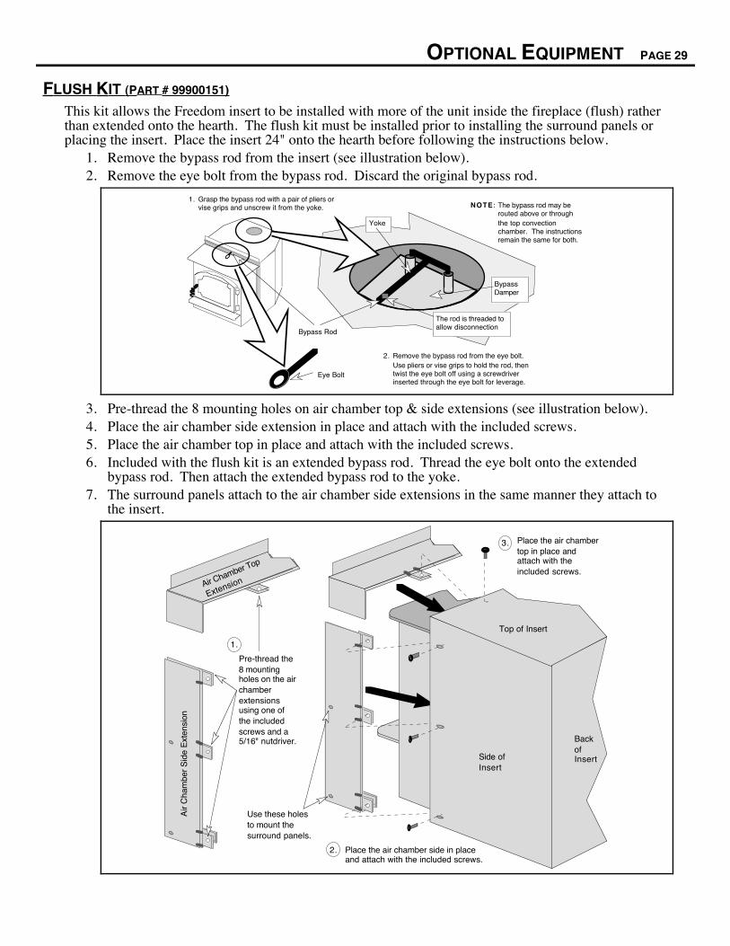
FLUSH KIT (PART # 99900151)
This kit allows the Freedom insert to be installed with more of the unit inside the fireplace (flush) ratherthan extended onto the hearth. The flush kit must be installed prior to installing the surround panels orplacing the insert. Place the insert 24" onto the hearth before following the instructions below.
1. Remove the bypass rod from the insert (see illustration below).2. Remove the eye bolt from the bypass rod. Discard the original bypass rod.
Yoke
Bypass Damper
Bypass Rod
The rod is threaded to allow disconnection
The bypass rod may be routed above or through the top convection chamber. The instructions remain the same for both.
NOTE : Grasp the bypass rod with a pair of pliers or vise grips and unscrew it from the yoke.
1.
Remove the bypass rod from the eye bolt. Use pliers or vise grips to hold the rod, then twist the eye bolt off using a screwdriver inserted through the eye bolt for leverage.
2.
Eye Bolt
3. Pre-thread the 8 mounting holes on air chamber top & side extensions (see illustration below).4. Place the air chamber side extension in place and attach with the included screws.5. Place the air chamber top in place and attach with the included screws.6. Included with the flush kit is an extended bypass rod. Thread the eye bolt onto the extended
bypass rod. Then attach the extended bypass rod to the yoke.7. The surround panels attach to the air chamber side extensions in the same manner they attach to
the insert.
1.
3.
2.
Pre-thread the 8 mounting holes on the air chamber extensions using one of the included screws and a 5/16" nutdriver.
Place the air chamber side in place and attach with the included screws.
Back of Insert
Top of Insert
Place the air chamber top in place and attach with the included screws.
Use these holes to mount the surround panels.
Air Chamber Top
Extension
Air
Cha
mbe
r S
ide
Ext
ensi
on
Side of Insert
PAGE 30 OPTIONAL EQUIPMENT (CONTINUED)
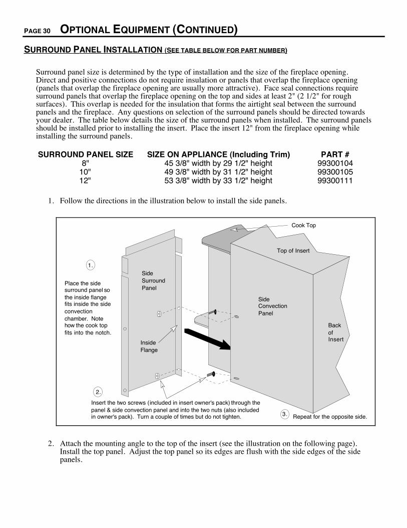
SURROUND PANEL INSTALLATION (SEE TABLE BELOW FOR PART NUMBER)
Surround panel size is determined by the type of installation and the size of the fireplace opening.Direct and positive connections do not require insulation or panels that overlap the fireplace opening(panels that overlap the fireplace opening are usually more attractive). Face seal connections requiresurround panels that overlap the fireplace opening on the top and sides at least 2" (2 1/2" for roughsurfaces). This overlap is needed for the insulation that forms the airtight seal between the surroundpanels and the fireplace. Any questions on selection of the surround panels should be directed towardsyour dealer. The table below details the size of the surround panels when installed. The surround panelsshould be installed prior to installing the insert. Place the insert 12" from the fireplace opening whileinstalling the surround panels.
SURROUND PANEL SIZE SIZE ON APPLIANCE (Including Trim) PART #8" 45 3/8" width by 29 1/2" height 99300104
10" 49 3/8" width by 31 1/2" height 9930010512" 53 3/8" width by 33 1/2" height 99300111
1. Follow the directions in the illustration below to install the side panels.
Back of Insert
Top of Insert
Insert the two screws (included in insert owner's pack) through the panel & side convection panel and into the two nuts (also included in owner's pack). Turn a couple of times but do not tighten.
1.
3.
2.
Place the side surround panel so the inside flange fits inside the side convection chamber. Note how the cook top fits into the notch.
Cook Top
Repeat for the opposite side.
Side Convection Panel
Inside Flange
Side Surround Panel
2. Attach the mounting angle to the top of the insert (see the illustration on the following page).Install the top panel. Adjust the top panel so its edges are flush with the side edges of the sidepanels.
OPTIONAL EQUIPMENT (CONTINUED) PAGE 31
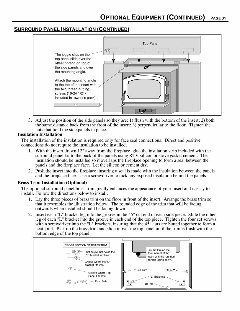
SURROUND PANEL INSTALLATION (CONTINUED)
The joggle clips on the top panel slide over the offset portion on top of the side panels and over the mounting angle.
Top Panel
Attach the mounting angle to the top of the insert with the two thread-cutting screws (10-24 1/2" - included in owner's pack).
3. Adjust the position of the side panels so they are: 1) flush with the bottom of the insert; 2) boththe same distance back from the front of the insert; 3) perpendicular to the floor. Tighten thenuts that hold the side panels in place.
Insulation InstallationThe installation of the insulation is required only for face seal connections. Direct and positiveconnections do not require the insulation to be installed.
1. With the insert drawn 12" away from the fireplace, glue the insulation strip included with thesurround panel kit to the back of the panels using RTV silicon or stove gasket cement. Theinsulation should be installed so it overlaps the fireplace opening to form a seal between thepanels and the fireplace face. Let the silicon or cement dry.
2. Push the insert into the fireplace, insuring a seal is made with the insulation between the panelsand the fireplace face. Use a screwdriver to tuck any exposed insulation behind the panels.
Brass Trim Installation (Optional)The optional surround panel brass trim greatly enhances the appearance of your insert and is easy toinstall. Follow the directions below to install.
1. Lay the three pieces of brass trim on the floor in front of the insert. Arrange the brass trim sothat it resembles the illustration below. The rounded edge of the trim that will be facingoutwards when installed should be facing down.
2. Insert each "L" bracket leg into the groove in the 45° cut end of each side piece. Slide the otherleg of each "L" bracket into the groove in each end of the top piece. Tighten the four set screwswith a screwdriver into the "L" brackets, insuring that the 45° cuts are butted together to form aneat joint. Pick up the brass trim and slide it over the top panel until the trim is flush with thebottom edge of the top panel.
"L" Brackets
Top Trim
Left Trim Right Trim
CROSS SECTION OF BRASS TRIM
Set screw that holds the "L" bracket in place
Groove where the "L" bracket fits into
Groove Where Top Panel Fits Into
Front Side
InsertLay the trim on the floor in front of the insert with the rounded portion facing down.
PAGE 32 OPTIONAL EQUIPMENT (CONTINUED)
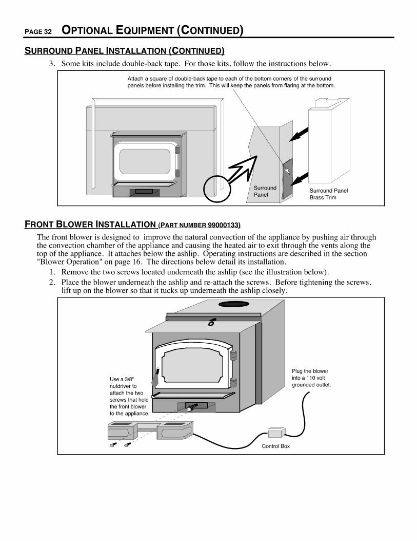
SURROUND PANEL INSTALLATION (CONTINUED)3. Some kits include double-back tape. For those kits, follow the instructions below.
Attach a square of double-back tape to each of the bottom corners of the surround panels before installing the trim. This will keep the panels from flaring at the bottom.
Surround Panel
Surround Panel Brass Trim
FRONT BLOWER INSTALLATION (PART NUMBER 99000133)
The front blower is designed to improve the natural convection of the appliance by pushing air throughthe convection chamber of the appliance and causing the heated air to exit through the vents along thetop of the appliance. It attaches below the ashlip. Operating instructions are described in the section"Blower Operation" on page 16. The directions below detail its installation.
1. Remove the two screws located underneath the ashlip (see the illustration below).2. Place the blower underneath the ashlip and re-attach the screws. Before tightening the screws,
lift up on the blower so that it tucks up underneath the ashlip closely.
Control Box
Use a 3/8" nutdriver to attach the two screws that hold the front blower to the appliance.
Plug the blower into a 110 volt grounded outlet.
OPTIONAL EQUIPMENT (CONTINUED) PAGE 33
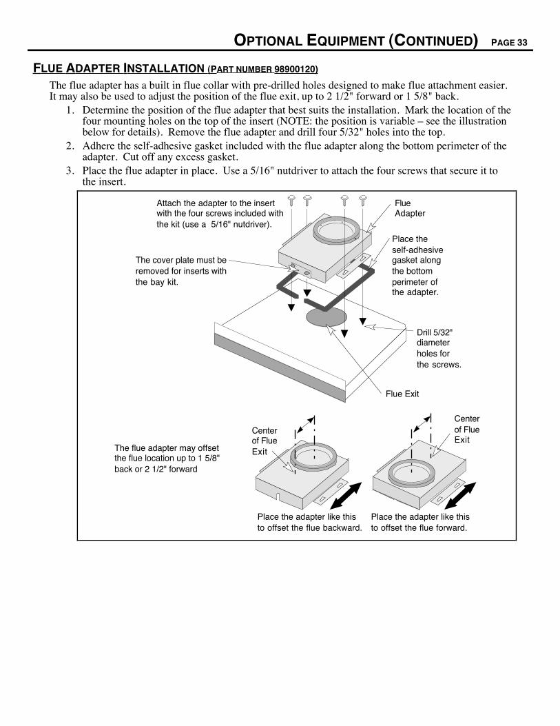
FLUE ADAPTER INSTALLATION (PART NUMBER 98900120)
The flue adapter has a built in flue collar with pre-drilled holes designed to make flue attachment easier.It may also be used to adjust the position of the flue exit, up to 2 1/2" forward or 1 5/8" back.
1. Determine the position of the flue adapter that best suits the installation. Mark the location of thefour mounting holes on the top of the insert (NOTE: the position is variable Ð see the illustrationbelow for details). Remove the flue adapter and drill four 5/32" holes into the top.
2. Adhere the self-adhesive gasket included with the flue adapter along the bottom perimeter of theadapter. Cut off any excess gasket.
3. Place the flue adapter in place. Use a 5/16" nutdriver to attach the four screws that secure it tothe insert.
Place the self-adhesive gasket along the bottom perimeter of the adapter.
Attach the adapter to the insert with the four screws included with the kit (use a 5/16" nutdriver).
Drill 5/32" diameter holes for the screws.
Flue Exit
Flue Adapter
The cover plate must be removed for inserts with the bay kit.
The flue adapter may offset the flue location up to 1 5/8" back or 2 1/2" forward
Center of Flue Exit
Place the adapter like this to offset the flue forward.
Place the adapter like this to offset the flue backward.
Center of Flue Exit

PAGE 34 INDEX
Adjusting the Heat Output ............................................ 14
Air Control Settings ...................................................... 12
Ash Removal................................................................ 19
Baffle (removal and replacement) ................................ 23
Block-Off Plate Installation ........................................... 9
Blower (cleaning) ......................................................... 22
Blower (installation)...................................................... 32
Blower (operation)........................................................ 16
Brass Cleaning............................................................. 19
Brass Trim Installation (for panels)............................... 31
BTU Output .................................................................. 5
Bypass Control ............................................................. 13
Chimney Inspection (Creosote Inspection) .................. 19
Chimney Requirements (Masonry Fireplace Req.) ...... 8
Clearances ................................................................... 7
Creosote Inspection ..................................................... 19
Dimensions................................................................... 5
Direct Connection......................................................... 10
Door (Inspection) ......................................................... 20
Door Cam..................................................................... 20
Door Gasket ................................................................. 21
Door Hinge (lubricating) ............................................... 21
Efficiency...................................................................... 5
Emissions..................................................................... 5
EPA Emission .............................................................. 5
Face Seal Connection.................................................. 11
Fan Cleaning (Blower) ................................................. 22
Fan Installation (Blower) .............................................. 32
Fan Operation (Blower)................................................ 16
Firebox Size ................................................................. 5
Firebrick (inspection and cleaning) ............................. 22
Firebrick (removal and replacement) ........................... 23
Fireplace Requirements ............................................... 8
Fireplace Sizing ........................................................... 7
Floor Protection (see Hearth Requirements) ............... 7
Flue Adapter Installation .............................................. 33
Flue Size (6") ............................................................... 5
Flush Kit Installation ..................................................... 29
Fuel to Use (cord wood only) ....................................... 17
Glass (Inspection) ........................................................ 20
Glass Cleaning............................................................. 19
Glass or Glass Gasket ................................................. 21
Hearth Requirements ................................................... 7
Heating Capacity.......................................................... 5
Insert Placement Requirements................................... 7
Insert Size Requirements............................................. 7
Insulation Installation (for panels) ................................ 31
Leveling Bolt Installation .............................................. 8
Listing Information........................................................ 28
Location of Controls ..................................................... 12
Log Length (Up to 24") ................................................. 5
Maintenance Schedule................................................. 19
Masonry Fireplace Requirements ................................ 8
Offset (Flue Adapter) ................................................... 33
Optional Equipment Requirements .............................. 6
Overnight Burn ............................................................. 15
Paint (touch-up) ........................................................... 22
Paint Curing ................................................................. 12
Panels .......................................................................... 30
Parts List ...................................................................... 25
Positive Connection ..................................................... 10
Reloading Your Appliance ........................................... 14
Replacement Parts List ................................................ 25
Safety Label ................................................................. 28
Safety Precautions ....................................................... 2
Secondary Air Tube (replacement) .............................. 25
Secondary Air Tube (warranty - 5 yrs) ......................... 27
Specifications ............................................................... 5
Starting the Fire ........................................................... 13
Surround Panel Installation.......................................... 30
Table of Contents......................................................... 4
Troubleshooting Table ................................................. 26
Warranty....................................................................... 27
Weight (Dimensions).................................................... 5
Wood Types ................................................................. 17