Embed Size (px)
Citation preview
PAPERS
Frequency-Warped Signal Processing for AudioApplications*
AKI HARM_,, 1 MATTI KARJALAINEN, 1AES Fellow, LAURI SAVIOJA 2, AES Member,
VESA VALIMAKI, 1 AES Member, UNTO K. LAINE, 1 AES Member, AND JYRI HUOPANIEMI, 3 AES Member
l Helsinki University of Technology, Laboratory of Acoustics and Audio Signal Processing,FIN-02015 HUT, Espoo, Finland
2 Helsinki University of Technology, Telecommunications Software and Multimedia Laboratory,FIN-02015 HUT, Espoo, Finland
3 Nokia Research Center, Speech and Audio Systems Laboratory, Helsinki, Finland
Modern audio techniques, such as audio coding and sound reproduction, emphasize themodeling of auditoryperception as one of thecornerstones for systemdesign. A methodology,frequency-warped digital signal processing, is presented in a tutorial paper as a means todesign or implementdigital signal-processingalgorithms directly in a way that is relevantfor auditory perception. Several audio applicationsare considered in which this approachshows advantageswhenused asa designor implementationtool or asa conceptualframeworkof design.
0 INTRODUCTION The conventional frequency scale used in digitalsignal-processing (DSP) systems is linear in relation to
The human auditory system is a very complex ana- the hertz scale, that is, the inherent frequency resolutionlyzer that is nonlinear, time-variant, and adaptive in is uniform for the whole band from de to the Nyquistmany ways. Thus models of auditory perception are nee- limit (half the sampling frequency fs)- The reason foressarily complex, and audio techniques that utilize such this is the property of the unit delay z- i, the basic DSPprinciples are intricate. Only few properties of the audi- building block, which delays signal components of alltory system are such that they can be exploited easily frequencies by the same amount: delay = 1/sample rate.and systematically in audio signal processing. For example, a sample sequence, when Fourier trans-
The most often utilized auditory feature in this sense formed, results in frequency bins that are equidistantare the pitch scales, that is, auditory "frequency" scales, in frequency.which are nonlinear and nonuniform in relation to the There are of course ways to avoid this property ofhertz scale. Examples are the mel scale [1], the Bark uniform frequency resolution. Recursive filters (IIR ill-scale (critical-band rate scale) [2], and the ERB (equiva- ters) can easily be focused on desired portions of thelent rectangular-bandwidth) rate scale [3]. A close rela- Nyquist band to have sharper resonances and magnitudefive to them is the logarithmic scale, which has a long response transitions than in other parts ofthe frequencytradition of use in audio technology. In many audio ap- scale. However, it would be useful to be able to designplications it would be desirable to design signal- digital filters and algorithms directly on nonuniform fre-
pro_sing systems and algorithms that work directly quency scales, such as the Bark scale.on some of these auditory scales. For example, audio In this paper we discuss a general approach to design-equalizers typically should have such properties, and the ing and implementing DSP techniques on a warped fre-psychoacoustic models of audio codees approximate this quency scale that approximates well the Bark scale. Thekind of behavior, paper begins with an introduction to auditory frequency
scales in Section 1. In Section 2 the theory of frequency-* An earlier version of this paper was presented at the 108th warped DSP is introduced, and it is studied how well
Convention of the Audio Engineering Society (preprint 5171),in Paris, France, 2000 February 19-22. Manuscript received a warped system can approximate auditory frequency2000 February 8; revised 2000 August 31. representation. This is followed by an introduction to
J.AudioEng.Soc.,Vol.48,No.11,2000November 1011
I'IARM/i, ET AL. PAPERS
the design and implementation of warped FIR-type and filters, that is, auditory filters, may be obtained in manyIIR-type filters, which are the basic building blocks in different ways. Once a function representing the band-warped signal-processing algorithms, widths of the filters is found, a psychoacoustic frequency-
Several audio applications where frequency-warped position function may be obtained by integrating overtechniques have shown advantages are introduced in the frequency scale.Section 3. The warped fast Fourier transform and filter- A classical and still widely used psychoacoustic fre-bank techniques are reviewed, and it is demonstrated quency scale is based on the assumption that the earhow a conventional design of a uniform filter bank di- may be modeled as a filter bank of a large number ofrecfly produces a computationally efficient auditory filter overlapping filters. The bandwidth of those filters isbank if it is implemented using warped filters. Paramet- called the critical bandwidth. Based on several differentric techniques for spectral estimation, such as warped experiments, Scharf [2] concluded that listeners react inLP (WLP) modeling and adaptive filtering techniques, one way when the stimuli are wider than the criticalare also available. It is demonstrated that WLP is a band and in another way when the stimuli are narrower.potential technique for wide-band speech and audio cod- The theory of critical bandwidth postulates that the sameing. The gain that can be obtained by warping an LPC- bandwidth is used in loudness summation, phase sensi-type coding algorithm is shown in listening test results, tivity, harmonic discrimination, and several other psycho-
Finally, specific applications of warped filters to digi- acoustic phenomena.hal loudspeaker equalization, physical modeling of the Recently several authors have pointed out that this isguitar body, and implementation of head-related transfer not necessarily the case [5]. The built-in assumption thatfunctions are studied. There is also an example where the filters of the auditory system have rectangular shapes
warped techniques have been used to solve a slightly has also been criticized, and it has been shown that off-different problem. In this application, warped filters are band listening, which was not counted in the originalused to reduce dispersion errors in a digital waveguide experiments, may chang e observed effects significantlymesh, which is used in physical modeling of musical [6]. Furthermore, the technique used in determining theinstruments or acoustic spaces. Several other recent ap- critical bandwidths, especially at low frequencies, mayplications are also briefly reviewed, be inaccurate and based on incorrect assumptions [7].
Based on Scharf's data, a useful analytic expression
1 PITCH SCALES AND RESOLUTIONS for the critical bandwidth as a function of frequency isgiven by [8]
1.1 Cochlear Mapping
Based on measurementsof the mechanical motion of [ ( , _21°'69the cochlea and neural recordings, Greenwood intro- AfeB = 25 + 75 1 + 1.4 \_zz/J (4)duced a general analytic expression for the cochlearfrequency-position function [4]. For humans it is where the unit is the Bark. Scharf remarked that the
given by values may differ by as much as -+15% among subjects.A corresponding frequency-position function defines
f = 165.4 (10 °-°_ - 1) (1) a scale called the Bark rate scale. A suitable approxima_
and tion is given by [8]
x : 0_06l°g'° (f-165.4165"4_,/ (2) v= 13 arctan (0.76 _-Hz) + 3.5 arctan (7.5fHZ) 2 .(5)
where x is the location on the cochlea (in millimeters)
andfis its characteristic frequency (in hertz) correspond- A technique that was designed so that these problemsing to that position. It is usually assumed that the same can be eliminated was introduced in [6]. In this tech-frequency representation is als0 preserved at higher neu- nique, a notched noise masker was_used in a novel wayral stages of the hearing mechanism [5]. to find the shapes of auditory filters of the filter-bank
The first derivative of Eq. (1) is model. The bandwidth of an auditory filter is often char-acterized by its equivalent rectangular bandwidth
df- 22.9 X 10°:°c_ = 22.9f 161565"4 (3) (ERB), that is, the bandwidth of a rectangular filter that- passes the same amount of signal energy as the auditoryfilter. The following analytic expression for the ERB as
Here dfldx is a function describing the bandwidth re- a function of frequency was proposed in [3]:lated to a l-ram range on the cochlea.
S_les__ AfE _ = 24.7 + 0.108fc (6)Paychoacoustlc1.2
Psychoacoustic scales are usually based on a filter- wherefc is the center frequency of the filter. The equationbank model of the hearing mechanism (see, for example, is actually reliable only in the frequency range from 100[6] for a review). Estimates of the bandwidths of the Hz to 10 kHz because ERBs have not been measured at
1012 J. AudioEng. Soc., Vol. 48, No. 11, 2000 November
PAPERS SIGNALPROCESSINGFORAUDIOAPPLICATIONS
very low and very high frequencies. The corresponding tory frequency scales are between linear and logarith-ERB scale can be calculated by mic scales.
Since the ERB rate scale found by using psycho-
f [ df acoustic listening tests and the frequency-to-positiondx = - 24.7 -_O.108f (7) scale derived from physiological and neural measure-ments coincide, the ERB rate scale may be considered
and to be a more accurate model than the Bark scale.
1x - 1n(24.7 + 0.108f) + C 2 FREQUENCY WARPING AND WARPED
0.108 DIGITAL FILTERS
= 21.3 1og(24.7 + 0.108f) + C The technique of computing nonuniform-resolutionFourier transforms using first-order all-pass filters was
[log (1 + 0.108 ._ _ 1og(24.7)] + C. introduced by Oppenheim, Johnson, and Steiglitz [9],21.3
_J) [10]. They used the warping technique with the FFT tocompute •a nonuniform spectral representation of a signal
Sincef(x = 0) = 0, the equation reduces to [11]. Mathematically, there was nothing new in thistechnique--a trivial modification of the Fourier trans-
(2-_9) form. The novelty was in the implementation with a1 (8) network of digital filters. The idea of frequency-warpedx 21.3 log +
transfer functions dates back to a paper by Schiissler
or 4.5 ....
f_- 229(1(W 21"3 1) (9) 4 GB/GB-- . ................ BarlVGBERB/GB
3.5 1/3octave/GB
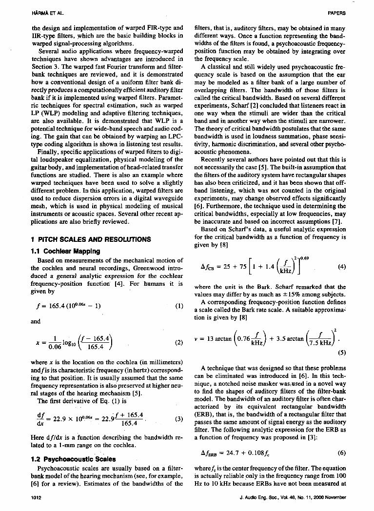
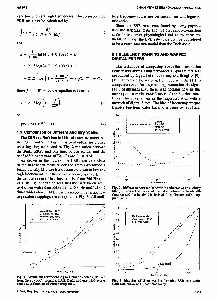
1.3 Comparison of Different Auditory Scales _ ,3 "x
The ERB and Bark bandwidth estimates are compared _ ",in Figs. 1 and 2. In Fig. 1 the bandwidths are plotted _ 2.5 ",on a log-log scale, and in Fig. 2 the ratios between _ ""
the Bark, ERB, and one-third-octave bands, and the _ 2 ", .-"bandwidth expression of Eq. (3) are illustrated. _ 1.5 "- ....... /"
As shown in the figures, the ERBs are very close "to the bandwidth measure derived from Greenwood's 1 ....
formula in Eq. (3). The Bark bands are wider at low and 0.5 .....high frequencies, but the correspondence is excellent atthe central range of hearing, that is, from 700 Hz to 4 0 .......................10 2 103 10 4
kHz. In Fig. 2 it can be seen that the Bark bands are 2 Frequency[Hz]to 4 times wider than ERBs below 200 Hz and 1.5 to 2 Fig. 2. Differencebetweenbandwidthestimatesof anauditorytimes wider above 5 kHz. The corresponding frequency- filter, illustrated in terms of the ratio between a bandwidth
function and the bandwidth derived from Greenwood's map-to-position mappings are compared in Fig. 3. All audi- ping (GB).
• .., ., , •
Bark(Schaff,1970)I / 1 ......_._ Greenwood,1990 .J . 0.9ERB(Moore,1990) J /_" _. Barkratescale___
./..._/ ...... Greenwood,1990 /_.;.;; / .]1/3 octavebands I . 0.8 l- -- ER
gle ¢¢j- o_0.6
,_ .. / 0.5/ //t_
• 0.4
0.310 2 ._
..:_5_-" 0.2
_'_ " _:_'_ 0.1 _ Linear_,_
102 103 104 0 _' ' '_ ...... ' ........ ' ,Frequency[Hz] 102 103 104
Fig. 1. Bandwidth corresponding to 1 mm on cochlea, derived Frequency[Hz]from Greenwood's formula, ERB, Bark, and one-third-octave Fig. 3. Mapping of Greenwood's formula, ERB rate scale,bands as a function of center frequency. Bark rate scale, and linear frequency.
J. Audio Eng.Soc., Vol. 48, No. 11, 2000 November 1013
H./d:U_O,ET At.. PAPERS
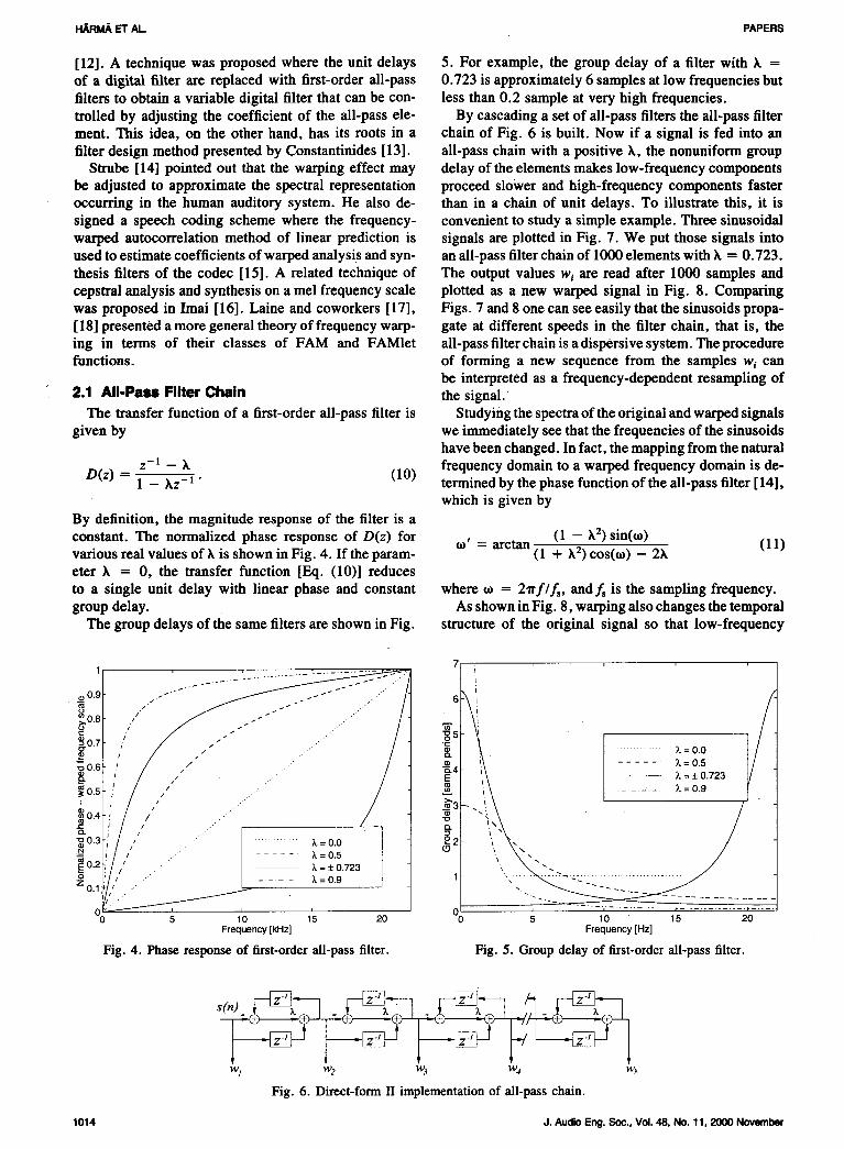
[12]. A technique was proposed where the unit delays 5. For example, the group delay of a filter with k =of a digital filter are replaced with first-order all-pass 0.723 is approximately 6 samples at low frequencies butfilters to obtain a variable digital filter that can be con- less than 0.2 sample at very high frequencies.
trolled by adjusting the coefficient of the all-pass ele- By cascading a set of all-pass filters the all-pass filtermerit. This idea, on the other hand, has its roots in a chain of Fig. 6 is built. Now if a signal is fed into anfilter design method presented by Constantinides [13]. all-pass chain with a positive k, the nonuniform group
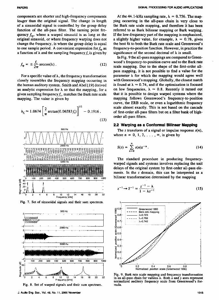
Strube [14] pointed out that the warping effect may delay ofthe elements makes low-frequency componentsbe adjusted to approximate the spectral representation proceed slower and high-frequency components fasteroccurring in the human auditory system. He also de- than in a chain of unit delays. To illustrate this, it issigned a speech coding scheme where the frequency- convenient to study a simple example. Three sinusoidalwarped autocorrelation method of linear prediction is signals are plotted in Fig. 7. We put those signals intoused to estimate coefficients of warped analysis and syn- an all-pass filter chain of 1000 elements with k = 0.723.thesis filters of the codec [15]. A related techniquel of The output values wi are read after 1000 samples andcepstral analysis and synthesis on a mel frequency scale plotted as a new warped signal in Fig. 8. Comparingwas proposed in Imai [16]. Laine and coworkers [17], Figs. 7 and 8 one can see easily that the sinusoids propa-[18] presented a more general theory of frequency warp- gate at different speeds in the filter chain, that is, theing in terms of their classes of FAM and FAMlet all-pass filter chain is a dispersive system. The procedurefunctions, of forming a new sequence from the samples wi can
be interpreted as a frequency-dependent resampling of2.1 All-Pass Filter Chain the signal."
The transfer function of a first-order all-pass filter is Studying the spectra of the original and warped signalsgiven by we immediately see that the frequencies of the sinusoids
have been changed. In fact, the mapping from the naturalz-1 _ k frequency domain to a warped frequency domain is tie-
D(z) - 1 - Xz- 1 • (10) termined by the phase function of the all-pass filter [14],which is given by
By definition, the magnitude response of the filter is a
constant. The normalized phase response of D(z) for to' = arctan (1 - k2) sin(to) (11)various real values of k is shown in Fig. 4. If the param- (1 + k2) cos(to) - 2keter k = 0, the transfer function [Eq. (10)] reduces
to a single unit delay with linear phase and constant where to = 2"trf/f,, and f, is the sampling frequency.group delay. As shown in Fig. 8, warping also changes the temporal
The group delays of the same filters are shown in Fig. structure of the original signal so that low-frequency
1 _, ................ =_ : 7 i
¢vO.9 , s _ .Y'
_o.81- , _ .-.s ........ /
,,,/ .--'" •."' / ............. =o.oI- _ !\ ...... _=0.5 oo, / / ......... ! °
!\ -- X = + 0.723
_o._F_/ / ' / _ i\ .........x=o._
i _/! // ...... Z=_(:).723 I. >" _ \ " /
,i /i/ ,' " ...... " I == ',.8o.ah / _ ........... _.=o.o I _°2 " -N / .'
o Pl--......---. I ° ' "
_001__ ......... _,=0.9 I 1-I'0 ' ' O(00 5 15 20 5 10 15 20
Frequency[kHz] Frequency[Hz]
Fig. 4. Phase response of first-order all-pass filter. Fig. 5. Group delay of first-order all-pass filter.
1" 1 I 1 1wz w2 w3 w_ w_
Fig. 6. Direct-form II implementation of all-pass chain.
1014 J. Audio Eng. Soc., Vol. 48, No. 11, 2000 November
PAPERS SIGNAL PROCESSING FOR AUDIO APPLICATIONS
components are shorter and high-frequency components At the 44. l-kHz sampling rate, k = 0.756. The map-longer than the original signal. The change in length ping occurring in the all-pass chain is very close toof a sinusoidal signal is controlled by the group delay the Bark rate scale mapping, and therefore ithas beenfunction of the all-pass filter. The turning point fre- referred to as Bark bilinear mapping or Bark warping.
quency ftv, where a warped sinusoid is as long as the If the low-frequency part of the mapping is emphasized,original sinusoid, or where frequency warping does not a slightly higher value, for example, k = 0.78, giveschange the frequency, is where the group delay is equal the best fit to both the Bark rate scale and Greenwood's
to one sample period. A convenient expression forftp as frequency,to-position function. However, in practice thea function of k and the sampling frequencyf_ is given by significance of the second decimal of k is small.
In Fig. 9 the all-pass mappings are compared to Green-
+ f' arccos(k) (12) wood's frequency-to-position curve and to the Bark rate- 2"a- " scale mapping. Due to the shape of the first-order all-
pass mapping, it is not possible to find a value for the
For a specific value of k, the frequency transformation parameter h for which the mapping would agree wellclosely resembles the frequency mapping occurring in with Greenwood's mapping. Globally, the closest matchthe human auditory system, smith and Abel [ 19] derived is found at k -_ 0.74, and if the optimization is focusedan analytic expression for h so that the mapping, for a on low frequencies, k = 0.8. Recently it turned outgiven sampling frequencyf_, matches the Bark rate scale that it is possible to design warped systems where themapping. The value is given by mapping follows Greenwood's frequency-to-position
curve, the ERB scale, or even a logarithmic frequency
[2 ]1/2 scale almost exactly. This is not based on the cascadekl, _ 1.0674 arctan(0.06583fs) - 0.1916. of first-order all-pass filters but on a filter bank of high-order all-pass filters.
(13)
2.2 Warping as a Conformal Bilinear Mapping
sopHz The z transform of a signal or impulse response s(n),
_oil /I /I /I /I /I /I /I /I /I/I/11t \/' _/'_/ '_/ '_/ \/ \/ \/' \/' \/' \/ I wheren =_0, 1,2 ..... 0%is given by2000 Hz
S(z) = __, s(n)z-". (14)
n=0_ The standard procedure in producing frequency-5000 Hz
1 warped signals and systems involves replacing the unit
i delays of the original system by first-order all-pass ele-ments. In the z domain, this can be interpreted as a
- o lOO 2oo 3o0 400 sop 8oo 700 800 9o0 lOOO bilinear transformation determined by the mapping
t_' 4oH2otJ/ z-1 _ X.oH/ z-l "--*_'-l -- (15)
__201J_ ......... 1 -- kz _10 2 4 6 8 10 12 14 16 18 20 22
Frequency[kHz]
Fig. 7. Set of sinusoidal signals and their sum spectrum. 1 .... - ,f
Oreeow 01 0..... Bark rate mapping _ _._,r
2[,,,,,,,,,^ _o8 ---- _=o723 _'/"o ..... o,o,0_VVVVV!VVVV_ _0.7 k=0.742 ,:,//
-2 ' 2000 HZ .... O_0-6
_0.5
:_0.45000 Hz _.
0.3
0.2
Z0.10 100 200 300 400 500 600 700 800 900 1000
1 ooo o o o50t_ Normalized position scale (Greenwood 1990)
0_ , , Fig. 9. Bark rate scale mappingand frequency transformation0 ...... 14 16 18 20 22 in an all-pass chain for various k. Both x and y axes represent
Frequency[kHz] normalized auditory frequency scale from Greenwood's for-Fig. 8. Set of warped signals and their sum spectrum, mula.
J. Audio Eng. Soc., Vol. 48, No. 11, 2000 November 1015
I-I/i,RMAETAL. PAPERS
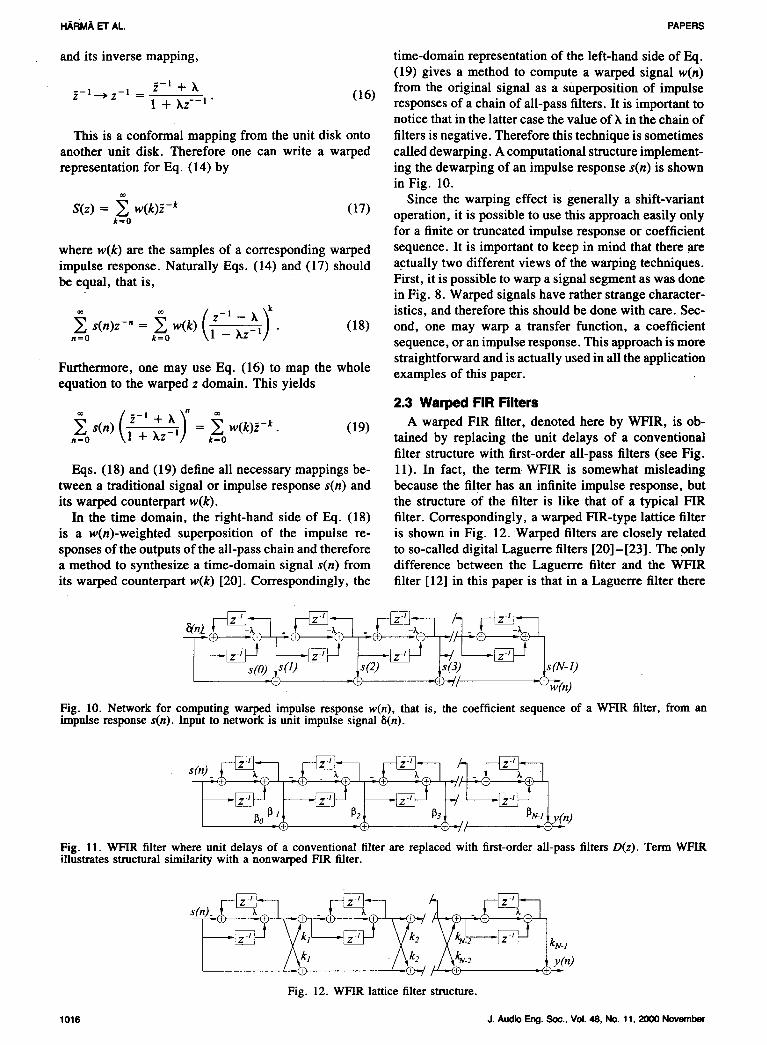
and its inverse mapping, time-domain representation of the left-hand side of Eq.(19) gives a method to compute a warped signal w(n)
_-_ + h from the original signal as a superposition of impulse_,- ] ---->z- 1 = (16)1 + kz'- ] • responses of a chain of all-pass filters. It is important to
notice that in the latter case the value of k in the chain of
This is a conformal mapping from the unit disk onto filters is negative. Therefore this technique is sometimesanother unit disk. Therefore one can write a warped called dewarping. A computational structure implement-representation for Eq. (14) by ing the dewarping of an impulse response s(n) is shown
in Fig. 10.
Since the warping effect is generally a shift-variantS(z) = w(k)_ -k (17) operation, it is possible to use this approach easily onlyk=0
for a finite or truncated impulse response or coefficient
where w(k) are the samples of a corresponding warped sequence. It is important to keep in mind that there areimpulse response. Naturally Eqs. (14) and (17) should actually two different views of the warping techniques.be equal, that is, First, it is possibleto warpa signal segmentas wasdone
in Fig. 8. Warped signals have rather strange character-
_ (;____l_ k )_ istics, and therefore this should be done with care. Sec-s(n)z -n = w(k) _z_--1 . (18) ond, one may warp a transfer function, a coefficientn=0 _=o sequence, or an impulse response. This approach is more
straightforward and is actually used in all the applicationFurthermore, one may use Eq. (16) to map the whole examples of this paper.equation to the warped z domain. This yields
2.3 Warped FIR Filters
,_--o ( _-l + k-_" _ A warped FIR filter, denoted here by WFIR, is ob-s(n) i + kz -1] = w(k)z-k" (19)= _=0 tained by replacing the unit delays of a conventionalfilter structure with first-order all-pass filters (see Fig.
Eqs. (18) and (19) define all necessary mappings be- 11). In fact, the term WFIR is somewhat misleadingtween a traditional signal or impulse response s(n) and because the filter has an infinite impulse response, butits warped counterpart w(k). the structure of the filter is like that of a typical FIR
In the time domain, the right-hand side of Eq. (18) filter. Correspondingly, a warped FIR-type lattice filteris a w(n)-weighted superposition of the impulse re- is shown in Fig. 12. Warped filters are closely related
sponses of the outputs of the all-pass chain and therefore to so-called digital Laguerre filters [20]-[23]. The onlya method to synthesize a time-domain signal s(n) from difference between the Laguerre filter and the WFIRits warped counterpart w(k) [20]. Correspondingly, the filter [12] in this paper is that in a Laguerre filter there
Fig. 10. Network for computing warped impulse response w(n), that is, the coefficient sequence of a WFIR filter, from animpulse response s(n). Input to network is unit impulse signal 8(n).
Fig. 11. WFIR filter where unit delays of a conventional filter are replaced with first-order all-pass filters D(z). Term WFIRillustrates structural similarity with a nonwarped FIR filter.
,.9 , X--V2Fig. 12. WFIR lattice filter structure.
1016 J. Audio Eng. Soc., Vol. 48, No. 11, 2000 November
PAPERS SIGNALPROCESSINGFORAUDIOAPPLICATIONS
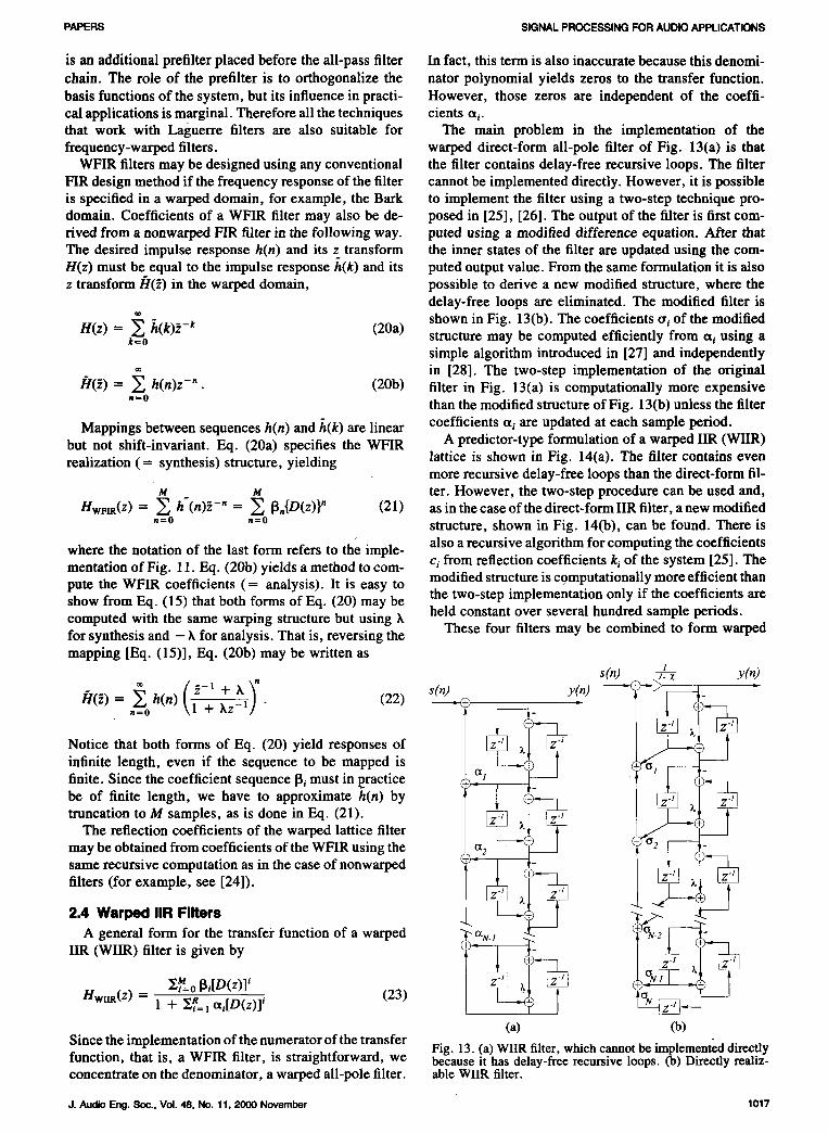
is an additional prefilter placed before the all-pass filter In fact, this term is also inaccurate because this denomi-chain. The role of the prefilter is to orthogonalize the nator polynomial yields zeros to the transfer function.
basis functions of the system, but its influence in practi- However, those zeros are independent of the coeffi-cal applications is marginal. Therefore all the techniques cients oti.that work with Laguerre filters are also suitable for The main problem in the implementation of thefrequency-warped filters, warped direct-form all-pole filter of Fig. 13(a) is that
WFIR filters may be designed using any conventional the filter contains delay-free recursive loops. The filterFIR design method if the frequency response of the filter cannot be implemented directly. However, it is possibleis specified in a warped domain, for example, the Bark to implement the filter using a two-step technique pro-domain. Coefficients of a WFIR filter may also be de- posed in [25], [26]. The output of the filter is first corn-rived from a nonwarped FIR filter in the following way. puted using a modified difference equation. After thatThe desired impulse response h(n) and its z transform the inner states of the filter are updated using the com-H(z) must be equal to the impulse response h(k) and its puted output value. From the same formulation it is alsoz transform f/(_,) in the warped domain, possible to derive a new modified structure, where the
delay-free loops are eliminated. The modified filter is
/".__(k)_,_ , shown in Fig. 13(b). The coefficients tri of the modifiedH(z) (20a)_=0 structure may be computed efficiently from a i using a
simple algorithm introduced in [27] and independently
in [28]. The two-step implementation of the originalf/(_) = h(n)z-". (20b) filter in Fig. 13(a) is computationally more expensive,=0 than the modified structure of Fig. 13(b) unless the filter
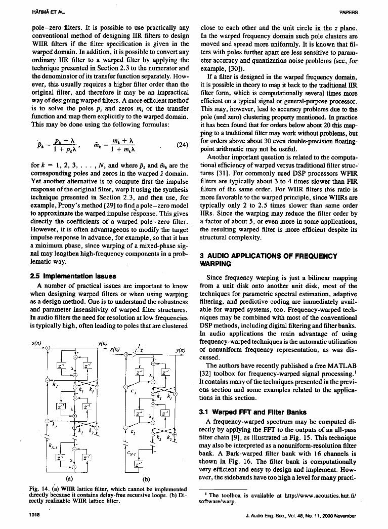
Mappings between sequences h(n) and h(k) are linear coefficients _q are updated at each sample period.but not shift-invariant. Eq. (20a) specifies the WFIR A predictor-type formulation of a warped IIR (WIIR)realization (= synthesis) structure, yielding lattice is shown in Fig. 14(a). The filter contains even
more recursive delay-free loops than the direct-form fil-m m ter. However, the two-step procedure can be used and,
Hvma(z) = _ h'(n)_- _ = _ 13.{D(z)}" (21) as in the case of the direct-form IIR filter, a new modified,=0 ,=0 structure, shown in Fig. 14(b), can be found. There is
where the notation of the last form refers to the imple- also a recursive algorithm for computing the coefficientsmentation of Fig. 11. Eq. (20b) yields a method to com- ci from reflection coefficients k_of the system [25]. The
modified structure is computationally more efficient thanpure the WFIR coefficients (= analysis). It is easy tothe two-step implementation only if the coefficients areshow from Eq. (15) that both forms of Eq. (20) may be
computed with the same warping structure but using k held constant over several hundred sample periods.for synthesis and - k for analysis. That is, reversing the These four filters may be combined to form warpedmapping [Eq. (15)], Eq. (20b) may be written as
s(n) I,t.z y(n)
[1('2) = h(n) . (22)
n=o 1 -I- XZ-I] " ) -)_
Notice that both forms of Eq. (20) yield responses of ii _._k_( _ __ ) _
infinite length, even if the sequence to be mapped isfinite. Since the coefficient sequence 13jmust in l_racticebe of finite length, we have to approximate h(n) bytruncation to M samples, as is done in Eq. (21).
The reflection coefficients of the warped lattice filter
may be obtained from coefficients of the WFIR using thesame recursive computation as in the case of nonwarped
filters (for example, see [24]). "- _t__ "_ l
2.4WarpedIIRFilters <" -
A general form for the transfer function of a warped _O_.N. 1 (_N-2 -
IIR (WHR) filter is given by "___._ ___N- *_'/_=o_i[D(z)]' (23)
Hwlm(Z) = 1 + Zix:] oti[D(z)] i
(a) (b)Since the implementation of the numerator of the transfer
Fig. 13. (a) WIIRfilter, which cannotbe implement_l directlyfunction, that is, a WFIR filter, is straightforward, we because it has delay-free recursive loops. (b) Directly realiz-concentrate on the denominator, a warped all-pole filter, able WIIR filter.
J.AudioEng.So(:.,Vol.48,No.11,2000November 1017
HARIV_ El" AL. PAPERS
pole-zero filters. It is possible to use practically any close to each other and the unit circle in the z plane.conventional method of designing IIR filters to design In the warped frequency domain such pole clusters areWlIR filters if the filter specification is given in the moved and spread more uniformly. It is known that fil-
warped domain. In addition, it is possible to convert any ters with poles further apart are less sensitive to param-ordinary HR filter to a warped filter by applying the eter accuracy and quantization noise problems (see, fortechnique presented in Section 2.3 to the numerator and example, [30]).
the denominator of its transfer function separately. How- If a filter is designed in the warped frequency domain,ever, this usually requires a higher filter order than the it is possible in theory to map it back to the traditional fiRoriginal filter, and therefore it may be an impractical filter form, which is computationaUy several times moreway of designing warped filters. A more efficient method efficient on a typical signal or general-purpose processor.is to solve the poles Pi and zeros m; of the transfer This may, however, lead to accuracy problems due to thefunction and map them explicitly to the warped domain, pole (and zero) clustering property mentioned. In practiceThis may be done using the following formulas: it has been found that for orders below about 20 this map-
ping to a traditional filter may work without problems, but
'- Pk + h thk _ m k + k (24) for orders above about 30 even double-precision floating-Pk - 1 + pkk ' 1 + mkk point arithmetic may not be useful.
Another important question is related to the computa-for k = 1, 2, 3 ..... N, and where/_ k and thk are the tional efficiency ofwarped versus traditional filter struc-corresponding poles and zeros in the warped _ domain, tures [31]. For commonly used DSP processors WFIRYet another alternative is to compute first the impulse filters are typically about 3 to 4 times slower than FIRresponse of the original filter, warp it using the synthesis filters of the same order. For WlIR filters this ratio istechnique presented in Section 2.3, and then use, for more favorable to the warped principle, since WlIRs are
example, Prony's method [29] to findapole-zero model typically only 2 to 2.5 times slower than same orderto approximate the warped impulse response. This gives IIRs. Since the warping may reduce the filter order bydirectly the coefficients of a warped pole-zero filter, a factor of about 5, or even more in some applications,However, it is often advantageous to modify the target the resulting warped filter is more efficient despite itsimpulse response in advance, for example, so that it has structural complexity.a minimum phase, since warping of a mixed-phase sig-
nal may lengthen high-frequency components in a prob- 3 AUDIO APPLICATIONS OF FREQUENCYlematic way. WARPING
2.5 Implementation Issues Since frequency warping is just a bilinear mappingA number of practical issues are important to know from a unit disk onto another unit disk, most of the
when designing warped filters or when using warping techniques for parametric spectral estimation, adaptiveas a design method. One is to understand the robustness filtering, and predictive coding are immediately avail-and parameter insensitivity of warped filter structures, able for warped systems, too. Frequency-warped tech-In audio filters the need for resolution at low frequencies niques may be combined with most of the conventionalis typically high, often leading to poles that are clustered DSP methods, including digital filtering and filter banks.
In audio applications the main advantage of using
s(n) y(n) frequency-warped techniques is the automatic utilization1
"> _ '_-_l_ -s(n) I-_ Y_(n) °fn°nunif°rmfrequencyrepresentati°n'aswasdis''(_" cussed.
_, The authors have recently published a free MATLAB[32] toolbox for frequency-warped signal processing)
_, It contains many of the techniques presented in the previ-
k! k I _clr__- _ OUSsection and some examples related to the applica-_ _ tions in this section.
3.1 Warped FIT and Filter Banks
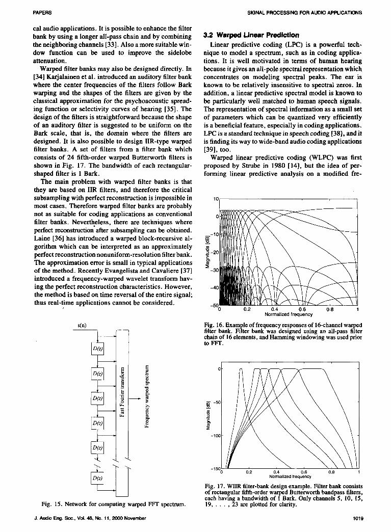
_k2 A frequency-warped spectrum may be computed di-rectly by applying the FFT to the outputs of an all-passfilter chain [9], as illustrated in Fig. 15. This technique
_1_ _____ may also be interpreted as a nonuniform-resolution filter
- bank. A Bark-warped filter bank with 16 channels isshown in Fig. 16. The filter bank is computationallyvery efficient and easy to design and implement. How-
(a) (b) ever, the sidebands have too high a level for many practi-
Fig. 14. (a) WIIR lattice filter, which cannot be implemented
directly because it contains delay-free recursive loops. (b) Di- i The toolbox is available at http://www.aeoustics.hut.fi/reetly realizable WlIR lattice filter, software/warp.
1018 J. Audio Eng.Soc., Vol. 48, No. 11, 2000 November
PAPERS SIGNALPROCESSINGFORAUDIOAPPLICATIONS
Cal audio applications. It is possibleto enhancethe filterhank by using a longer all-pass chain and by combining 3.2 Warped Linear Predictionthe neighboring channels [33]. Also a more suitable win- Linear predictive coding (LPC) is a powerful tech-dow function can be used to improve the sidelobe nique to model a spectrum, such as in coding applica-attenuation, tions. It is well motivated in terms of human hearing
Warped filter banks may also be designed directly. In because it gives an all-pole spectral representation which[34] Karjalainen et al. introduced an auditory filter bank concentrates on modeling spectral peaks. The ear iswhere the center frequencies of the filters follow Bark known to be relatively insensitive to spectral zeros. Inwarping and the shapes of the filters are given by the addition, a linear predictive spectral model is known toclassical approximation for the psychoacoustic spread- be particularly well matched to human speech signals.ing function or selectivity curves of hearing [35]. The The representation of spectral information as a small setdesign of the filters is straightforward because the shape of parameters which can be quantized very efficientlyof an auditory filter is suggested to be uniform on the is a beneficial feature, especially in coding applications.Bark scale, that is, the domain where the filters are LPC is a standard technique in speech coding [38], and itdesigned. It is also possible to design IIR-type warped is finding its way to wide-band audio coding applicationsfilter banks. A set of filters from a filter bank which [39], too.
consists of 24 fifth-order warped Butterworth filters is Warped linear predictive coding (WLPC) was firstshown in Fig. 17. The bandwidth of each rectangular- proposed by Strube in 1980 [14], but the idea of per-shaped filter is 1 Bark. forming linear predictive analysis on a modified fre-
The main problem with warped filter banks is thatthey are based on fIR filters, and therefore the critical
subsampling with perfect reconstruction is impossible in 10Imost cases. Therefore warped filter banks are probablynot as suitable for coding applications as conventional
filter banks. Nevertheless, there are techniques whereperfect reconstruction after subsampling can be obtained.
Laine [36] has introduced a warped block-recursive al-_ _-10 I/_//_/_gorithm which can be interpreted as an approximately =-2o_[[VU_IIIII/I/////\
perfect reconstruction nonuniform-resolution filter bank. _ IIIlllIllll I V /The approximation error is small in typical applications :_-30of the method. Recently Evangelista and Cavaliere [37]introduced a frequency-warped wavelet transform hav-
ing the perfect reconstruction characteristics. However, _4011111m_l_[tV/hthe method is based on time reversal of the entire signal;
thus real-time applications cannot be considered, so) 0.2 0.4 0.6 0.8
Normalizedfrequency
s(n) Fig. 16. Exampleof frequencyresponses of 16-channelwarpedfilter bank. Filter bank was designed using an all-pass filterchainof 16elements, and Hamming windowing was used priorto FFT.
L_
[_ ._ -_°o o'.2 o., o., o.,
Normalized frequency
Fig. 17. WIIR filter-bank design example. Filter bank consistsof rectangular fifth-order warped Butterworth bandpass filters,each having a bandwidth of 1 Bark. Only channels 5, 10, 15,
Fig. 15. Network for computing warped FFT spectrum. 19.... ,23 are plotted for clarity.
J.AudioEng.Soc.,Vol.48,No.11,2000November 1019
I"_RM._ ET AL. PAPERS
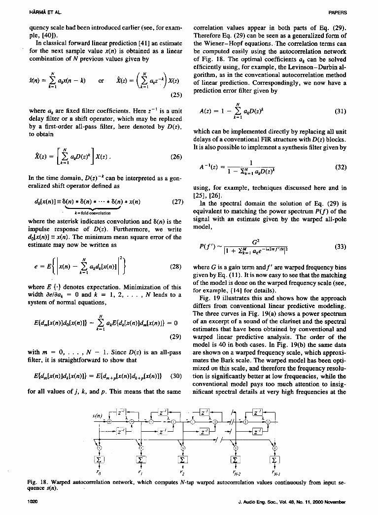
quency scale had been introduced earlier (see, for exam- correlation values appear in both parts of Eq. (29).pie, [40]). ThereforeEq. (29)canbe seenasa generalizedformof
In classical forward linear prediction [41] an estimate the Wiener-Hopf equations. The correlation terms canfor the next sample value x(n) is obtained as a linear be computed easily using the autocorrelation networkcombination of N previous values given by of Fig. 18. The optimal coefficients a k can be solved
efficiently using, for example, the Levinson-Durbin al-
(_ k) gorithm, as in the conventional autocorrelation method_n) = _ a_x(n - k) or X(z) = akz- X(z) of linear prediction. Correspondingly, we now have ak=l k=lprediction error filter given by
(25)N
where ak are fixed filter coefficients. Here z -1 is a unit A(z) = 1 - _ a_D(z) k (31)delay filter or a shift operator, which may be replaced _=lby a first-order all-pass filter, here denoted by D(z),to obtain which can be implemented directly by replacing all unit
delays of a conventional FIR structure with D(z) blocks.
It is also possible to implement a synthesis filter given by
X(z) = [,=_ aflg(z)k] X(z) . (26)A_l(z) = 1
1 - _=! aflg(z) k (32)In the time domain, D(z) -k can be interpreted as a gen-
eralized shift operator defined as using, for example, techniques discussed here and in[25], [26].
dk[x(n)] = 8(n) * 8(n) * ... * _(n) * x(n) (27) In the spectral domain the solution of Eq. (29) iskffifoldco_volution equivalent to matching the power spectrum P(f) of the
where the asterisk indicates convolution and 8(n) is the signal with an estimate given by the warped all-poleimpulse response of D(z). Furthermore, we write model,do[x(n)] = x(n). The minimum mean square error of the
G 2
estimate may now be written as P(f') _ I1 + 2_=_ake-i*2_f'/Sl2 (33)
xn, Ie = EL - akdk[x(n)] (28) where G is a gain term andf' are warped frequency binsk= _ given by Eq. (11). It is now easy to see that the matching
of the model is done on the warped frequency scale (see,where E {.} denotes expectation. Minimization of this for example, [14] for details).width c_e/Oak = 0 and k = 1, 2 ..... N leads to a Fig. 19 illustrates this and shows how the approachsystem of normal equations, differs from conventional linear predictive modeling.
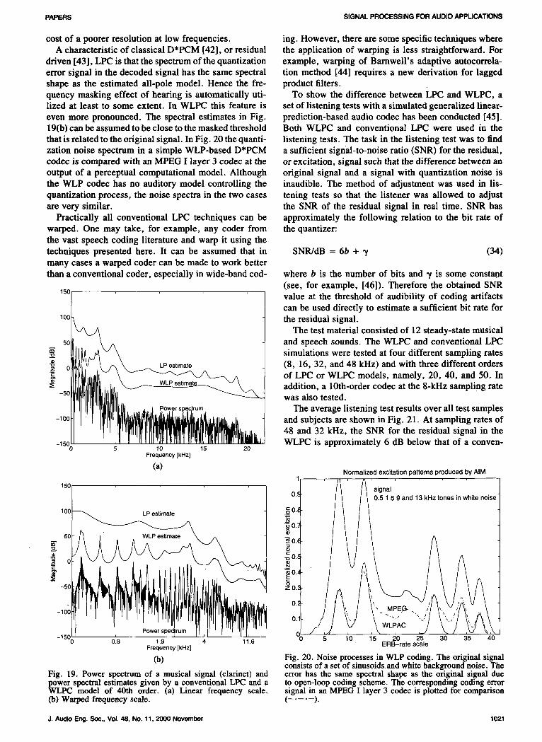
The three curves in Fig. 19(a) shows a power spectrum
E{dm[x(n)]do[x(n)]} - _] akE{dk[x(n)]dm[x(n)]} = 0 of an excerpt of a sound of the clarinet and the spectralk=_ estimates that have been obtained by conventional and
(29) warped linear predictive analysis. The order of themodel is 40 in both cases. In Fig. 19(b) the same data
with m = 0 ..... N - 1. Since D(z) is an all-pass are shown on a warped frequency scale, which approxi-filter, it is straightforward to show that mates the Bark scale. The warped model has been opti-
mized on this scale, and therefore the frequency resolu-
E{d_[x(n)]dk[x(n)]} = E{dm+p[x(n)]dk+p[x(n)]} (30) tion is significantly better at low frequencies, while theconventional model pays too much attention to insig-
for all values of j, k, and p. This means that the same nificant spectral details at very high frequencies at the
ro rl r2 %2 rN-I
Fig. i8. Warped autocorrelation network, which computes N-tap warped autocorrelation values continuously from input se-quence s(n).
1020 J.AudioEng.Soc.,Vol.48,No.11,2000November
PAPERS SIGNAL PROCESSING FOR AUDIO APPLICATIONS
cost of a poorer resolution at low frequencies, ing. However, there are some specific techniques whereA characteristic of classical D*PCM [42], or residual the application of warping is less straightforward. For
driven [43], LPC is that the spectrum of the quantization example, warping of Barnwell's adaptive autocorrela-error signal in the decoded signal has the same spectral tion method [44] requires a new derivation for laggedshape as the estimated all-pole model. Hence the fre- product filters.quency masking effect of heating is automatically uti- To show the difference between LPC and WLPC, alized at least to some extent. In WLPC this feature is set of listening tests with a simulated generalized linear-even more pronounced. The spectral estimates in Fig. prediction-based audio codec has been conducted [45].19(b) can be assumed to be close to the masked threshold Both WLPC and conventional LPC were used in thethat is related to the original signal. In Fig. 20 the quanti- listening tests. The task in the listening test was to findzation noise spectrum in a simple WLP-based D*PCM a sufficient signal-to-noise ratio (SNR) for the residual,codec is compared with an MPEG I layer 3 codec at the or excitation, signal such that the difference between anoutput of a perceptual computational model. Although original signal and a signal with quantization noise isthe WLP codec has no auditory model controlling the inaudible. The method of adjustment was used in lis-quantization process, the noise spectra in the two cases tening tests so that the listener was allowed to adjustare very similar, the SNR of the residual signal in real time. SNR has
Practically all conventional LPC techniques can be approximately the following relation to the bit rate ofwarped. One may take, for example, any coder from the quantizer:
the vast speech coding literature and warp it using thetechniques presented here. It can be assumed that in SNR/dB = 6b + _/ (34)many cases a warped coder can be made to work betterthan a conventional coder, especially in wide-hand cod- where b is the number of bits and _/is some constant
(see, for example, [46]). Therefore the obtained SNR
is° / value at the threshold of audibility of coding artifacts
/ can be used directly to estimate a sufficient bit rate for
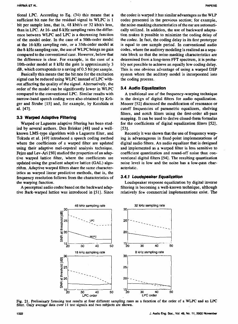
10o_ the residual signal.The test material consisted of 12 steady-state musical
_j_ simulations were tested at four different sampling rates0_U_.V .\ /-_ \ _/-. LPestirnate (8, 16, 32, and 48 kUz) and with three different orders
UlII_. __ZWL P_ of LPC or WLPC models, namely, 20, 40, and 50. In, hi ^ addition, a 10th-order codec at the 8-kHz sampling rate
Powersp rum The average listening test results over all test samples-100 andsubjectsareshownin Fig. 21. At samplingratesof
48 and 32 kHz, the SNR for the residual signal in the_ts011 _I'11!['l_rl IIgm"llt_lltj WLPC is approximately 6 dB below that of a conven-0 5 10 15 20
Frequency[kHz]
(a) Normalized excitation patterns produced by AIM
• 0.5 1 5 9 and 13 kHz tones in whitenoise
oO.%.= o -_0.
•-- I • /v
/
I 't/If-100 , MPE,G-. / "_
o ,,,,,,LP,,CJ " "-150 15 20 25 30 35 40
0 0.8 1.9 4 11.6 ERB-rate scaleFrequency [kHz]
(b) Fig. 20. Noise processes in WLP coding. The original signalconsists of a set of sinusoids and white background noise. The
Fig. 19. Power spectrum of a musical signal (clarinet) and error has the same spectral shape as the original signal duepower spectral estimates given by a conventional LPC and a to open-loop coding scheme. The corresponding coding errorWLPC model of 40th order. (a) Linear frequency scale, signal in an MPEG I layer 3 codec is plotted for comparison(b) Warped frequency scale. (-----.--).
J. Audio Eng. See., Vol. 48, No. 11, 2000 November 1021
I-IARMA ET AL. PAPERS
tional LPC. According to Eq. (34) this means that a the codec is warped it has similar advantages as the WLPsufficient bit rate for the residual signal in WLPC is 1 codec presented in the previous section; for example,bit per sample less, that is, 48 kbit/s or 32 kbit/s less, the n0ise-masking characteristics ofthe ear are automati-than in LPC. At 16- and 8-kHz sampling rates the differ- cally utilized. In addition, the use of backward adapta-ence between WLPC and LPC is a decreasing function tion makes it possible to minimize the coding delay ofof the model order. In the case of a 50th-order model the codec. In fact, the coding delay in its first prototypeat the 16-kHz sampling rate, or a 35th-order model at is equal to one sample period. In conventional audiothe 8-kHz sampling rate, the use of WLPC brings no gain codes, where the auditory modeling is realized as a sepa-compared to the conventional case. However, below that rate block so that the noise-masking characteristics arethe difference is clear. For example, in the case of a determined from a long-term FFT spectrum, it is proba-10th-order model at 8 kHz the gain is approximately 3 bly not possible to achieve an equally low coding delay.dB, which corresponds to a saving of 0.5 bit per sample. This is one obvious advantage of using a warped DSP
Basically this means that the bit rate for the excitation system where the auditory model is incorporated intosignal can be reduced using WLPC instead of LPC with- the coding process.out affecting the quality of the signal. Alternatively, theorder of the model can be significantly lower in WLPC 3.4 Audio Equalizationcompared to the conventional LPC, Similar results with A traditional use of the frequency-warping techniquenarrow-band speech coding were also obtained by Krfi- is the design of digital filters for audio equalization.ger and Strube [15] and, for example, by Koishida et Moorer [52] discussed the modification of resonance oral. [47]. cutoff frequencies of parametric equalizers, shelving
filters, and notch filters using the first-order all-pass3.3 Warped Adaptive Filtering mapping. It can be used to derive closed-form formulas
Warped or Laguerre adaptive filtering has been stud- for the coefficients of digital equalization filters [52],ied by several authors. Den Brinker [48] used a well- [53].known LMS-type algorithm with a Laguerre filter, and Recently it was shown that the use of frequency warp-Tokuda et al. [49] introduced a speech coding method ing is advantageous in fixed-point implementations ofwhere the coefficients of a warped filter are updated digital audio filters. An audio equalizer that is designedusing their adaptive mel-cepstral analysis technique, and implemented as a warped filter is less sensitive toFejzo and Lev-Ari [50] studied the properties of an adap- coefficient quantization and round-off noise than con-five warped lattice filter, where the coefficients are ventional digital filters [54]. The resulting quantizationupdated using the gradient adaptive lattice (GAL)algo- noise level is low and the noise has a low-pass char-rithm. Adaptive warped filters share the same character- acteristic.istics as warped linear predictive methods, that is, thefrequency resolution follows from the characteristics of 3,4.1 Loudspeaker £qualizationthe warping function. Loudspeaker response equalization by digital inverse
A perceptual audio codec based on the backward adap- filtering is becoming a well-known technique, althoughrive Bark-warped lattice was introduced in [51]. Since relatively few commercial implementations exist. The
48 kHz sampling rate 32 kHz sampling rate30 30113
--_o25 - - . LPC 25 _ -
_20 _ 20El: CZCO
15 1520 30 40 50 20 30 40 50
16 kHz sampling rate 8 kHz sampling rate30 30113
._ 25 25O3
20 _ _ _ _ _ _ _ 20 _ _ _
Z _ _ _ _ --_C'-_._._.0915 15
20 30 40 50 20 30 "40 50LPCorder LPCorder
Fig. 21. Preliminary listening test results at four different sampling rates as a function of the order of a WLPC and an LIEfilter. Only average data over 11 test signals and two subjects are shown.
1022 J. AudioEng. Soc., Vol. 48, No. 11, 2000 November
PAPERS SIGNALPROCESSINGFORAUDIOAPPUCATIONS
most common method is FIR equalization, but IIR filters derstood, and the body can be simulated efficiently byhave also been used. The equalization is applied either commuted synthesis, where the body response is usedto the magnitude response only or to both magnitude as excitation. Simulation of the body as a digital filter isand phase. The applicability of different equalizer filter computationally expensive [56], [57], and thus efficientstructures, including warped structures, has been corn- filter approximations are of interest.pared in [31]. A typical magnitude response of the acoustic guitar
FIR filters are very efficient at high frequencies. This body is shown in Fig. 23(a). It is measured by impactis due to the fact that FIRs inherently yield a uniform hammer excitation to the bridge of a guitar with dampedfrequency resolution while in audio the response speci- strings and by recording the response 1 meter in frontfications as well as the response measurements are given of the sound hole.typically on a logarithmic scale. Thus FIRs are particu- For a sample rate of 22 kHz, a simple FIR approxima-laxly problematic in equalization at low frequencies. IIR tion of the impulse response requires a filter order offilters avoid some of the problems found with FIRs, but about 2000-5000 for good results since the lowest reso-they are more difficult to design and they tend to share nances are sharp and they decay slowly. On the otherthe frequency resolution problem, hand, the high-frequency modes are much broader in
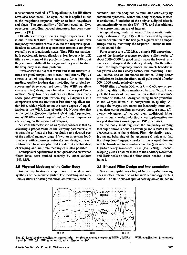
It was shown in [34] that WFIR and WIIR filter struc- bandwidth and thus decay faster. FIR modeling is nottures are good competitors to traditional filters. Fig. 22 well suited, and an IIR model fits better. Using linearshows a set of magnitude responses for a less than prediction to design the filter, an all-pole model of ordermedium-quality loudspeaker, including the original re- 500-1000 works relatively well.sponse and three equalized ones. The WIIR equalizer WFIR filters of order 500, with k = 0.63, are compa-(inverse filter) design was based on the warped Prony rable in quality to those mentioned before. WIIR filtersmethod. Very low filter orders (less than 10) already yield the lowest order approximation so that a denomina-show good overall equalization. Fig. 22 depicts also a tor order of 100-200, designed using linear predictioncomparison with the traditional FIR filter equalizer (or- in the warped domain, is comparable in quality. Al-der 105), which yields about the same degree of equal- though the warped structures are inherently more com-ization as the WIIR filter of order 24. Notice also that plex than corresponding unwarped ones, a small effi-while the FIR filter_loes the best job at high frequencies, ciency advantage of warped over traditional filtersthe WIIR filters work best at middle to low frequencies remains due to order reduction when implementing the(depending on the amount of warping), warped structures using typical DSP processors.
A useful characteristic of warped equalizers is that by In the body modeling case the frequency-warpingselecting a proper value of the warping parameter _, it technique shows a double advantage and a match to theis possible to focus the best resolution to a desired part characteristics of the problem. First, physically, warp-of the audio frequency range. If two- or three-way loud- ing means balancing of the resonance Q values so thatspeakers with crossover networks are designed, each the sharp low-frequency peaks in the warped domainsubband can have an optimized _, value. A combination will be broadened to resemble more the Q values of theof warping and multirate techniques is also possible, high-frequency resonance peaks [Fig. 23(b)]. Second,
Loudspeaker equalization techniques based on warped warping yields a natural match to the auditory resolutionfilters have been studied recently by other authors and Bark scale so that the filter order needed is min-I54], [55]. imized.
3.5 Physical Modeling of the Guitar Body 3.6 Binaural Filter Design and Implementation
Another application example concerns model-based Real-time digital modeling, of human spatial hearingsynthesis of the acoustic guitar. The modeling and real- cues is often referred to as binaural technology or 3-Dtime synthesis of string vibration are relatively well un- sound. The static cues of spatial hearing are contained in
100Hz 1kHz 10kHz
Fig. 22. Loudspeaker equalization curves, orig--original magnitude response; WIIR4, WIIR24--Wl]R equalization, filter orders4 and 24; P_IOb--P-vJR fiJtcr equalization, filter order 105.
J. Audio Eng.Soc, Vol. 48, No. 11, 2000 November 1023

I'_RMA ET AL PAPERS
head-related transfer functions (HRTFs). Traditionally, value at every node is updated at each sampling intervalHRTF filters have been created using minimum-phase using the state of the four neighboring nodes. It wasreconstruction and different FIR and IIR design methods shown that the method is suitable for sound synthesis(see [58] for a detailed summary). The use of warped of percussion instruments, although it suffers fromfilters in binaural and crosstalk canceled binaural filter direction-dependent dispersion [62]. In 1994 Savioja etdesign has been investigated in [59], [60]. Use of a al. extended the use of the digital waveguide mesh topsychoacoustically based frequency scale was found to three dimensions and presented simulation results ofbe well motivated for the binaural filter design as well, wave propagation in acoustic spaces [63].and a considerable reduction in filter order can be The main weakness of the digital waveguide meshachieved using warped designs. The transfer function technique is the dispersion error, which increases withexpressions of warped filters may be expanded (de- frequency. Due to dispersion, the digital waveguidewarped) to yield equivalent IIR filters of the traditional mesh method can be used for accurate numerical simula-form, such as direct-form II filters. 2 Such implementa- tions at low frequencies only, that is, the sampling fre-tions have been reported in the literature [61]. An alter- quency (in both time and space) must be very high innative strategy has been presented by the authors [56], acoustic simulations. The dispersion error appears as a[31], [58], [60], where implementation is carried out frequency error in the simulation results: the modes atdirectly in the warped domain using WFIR and WlIR high frequencies occur at incorrect frequencies. The fre-structures, quencydependenceimpliesthat the errorcausedby dis-
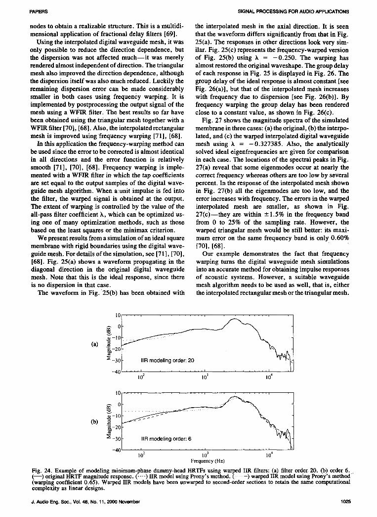
Theoretical and empirical investigations [58] have persion varies as a function of the direction of propaga-shown that dewarped WIIR structures outperform tradi- tion: the frequency of standing waves that are formedtional FIR and IIR design methods. In Fig. 24 IIR design in the diagonal direction--with respect to the samplingmethods with and without warping are compared. A grid--are exact, whereas the frequencies of standingCortex MK2 dummy head HRTF was used, and two waves in any other direction are too small, and the errorfilter orders (orders 20 and 6) were tested. The filters increases with frequency, that is, higher modes are dis-were designed using Prony's method (available in placed more than the lower ones.MATLAB [32]). For the warping a k value of 0.65 was A triangular waveguide mesh [64]-[66] has been de-chosen. It can clearly be seen from the results that the veloped to overcome the direction-dependent wave prop-fit at lower frequency is enhanced inWlIR designs with agation characteristics and dispersion error. It is baseda tradeoff of reduced high-frequency matching. Ac- on the idea that the sampling points are at comers ofcording to the psychoacoustic theory, this can be toler- equilateral triangles instead of squares. The interpolatedated. In summary, the use of auditorily motivated filter mesh was also devised to reduce the error while stilldesign in 3-D sound applications has a clear computa- using the convenient rectangular sampling grid [67],tional advantage without sacrificing perceptual accuracy. [68]. The key idea was that sample updates should ac-
count for more propagation directions than just four, as3.7 Improved Digital Wavegulde Mesh in the original mesh. The interpolation effectively insertsSimulations new nodesin the mesh--the contribution of the hypotheti-
The digital waveguide mesh was introduced in 1993 cal nodes is then spread over the existing neighboring[62]. It is a finite-difference time-domain simulation,
where the vibrating surface has been discretized. The 2 This unwarping method is subject to computational preei-model consists of a rectangular grid, where the signal sion problems at higher filter orders; see Section 2.5.
°fl.........30 " Original spectrum of the guitar body response
20
(a) _lli!
30
(b) 10
0¢ 1 I I I I I 1 I I I I I I I I I
-10d 200 500 1000 2000 3000 frequency/Hz
Fig. 23. Modeling of guitar body response. (a) Original magnitude response. (b) Magnitude response using WIIR modeling(notice warped frequency scale).
1024 J. Audio Eng.Soc., Vol. 48, No. 11, 2000 November
PAPERS SIGNALPROCESSINGFORAUDIOAPPLICATIONS
nodes to obtain a realizable structure. This is a multidi- the interpolated mesh in the axial direction. It is seen
mensional application of fractional delay filters [69]. that the waveform differs significantly from that in Fig.Using the interpolated digital waveguide mesh, it was 25(a). The responses in other directions look very sire-
only possible to reduce the direction dependence, but ilar. Fig. 25(c) represents the frequency-warped versionthe dispersion was not affected much--it was merely of Fig. 25(b) using k = -0.250. The warping has
rendered almost independent of direction. The triangular almost restored the original waveshape. The group delaymesh also improved the direction dependence, although of each response in Fig. 25 is displayed in Fig. 26. Thethe dispersion itself was also much reduced. Luckily the group delay of the ideal response is almost constant [seeremaining dispersion error can be made considerably Fig. 26(a)], but that of the interpolated mesh increasessmaller in both cases using frequency warping. It is with frequency due to dispersion [see Fig. 26(b)]. Byimplemented by postprocessing the output signal of the frequency warping the group delay has been renderedmesh using a WFIR filter. The best results so far have close to a constant value, as shown in Fig. 26(c).been obtained using the triangular mesh together with a Fig. 27 shows the magnitude spectra of the simulatedWFIR filter [70], [68]. Also, the interpolated rectangular membrane in three cases: (a) the original, (b) the interpo-mesh is improved using frequency warping [71], [68]. lated, and (c) the warped interpolated digital waveguide
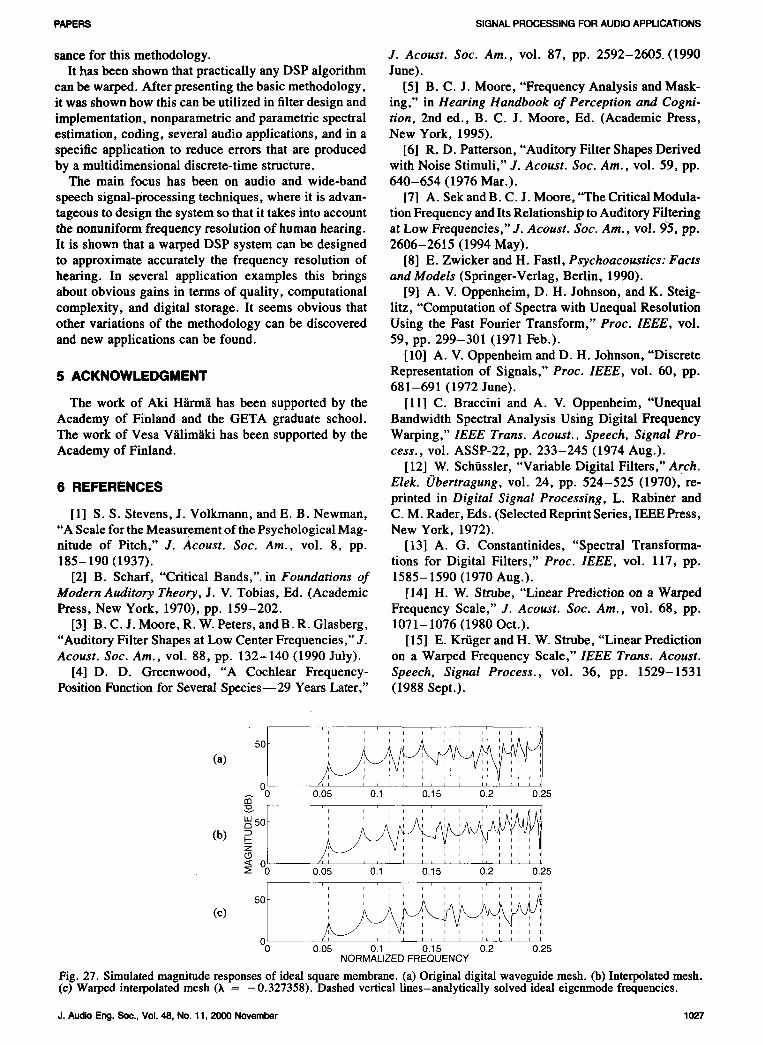
In this application the frequency-warping method can mesh using k = - 0.327385. Also, the analyticallybe used since the error to be corrected is almost identical solved ideal eigenfrequencies are given for comparisonin all directions and the error function is relatively in each case. The locations of the spectral peaks in Fig.smooth [71], [70], [68]. Frequency warping is imple- 27(a) reveal that some eigenmodes occur at nearly themoated with a WFIR filter in which the tap coefficients correct frequency whereas others are too low by severalare set equal to the output samples of the digital wave- percent. In the response of the interpolated mesh shownguide mesh algorithm. When aunit impulse is fed into in Fig. 27(b) all the eigenmodes are too low, and thethe filter, the warped signal is obtained at the output, error increases with frequency. The errors in the warpedThe extent of warping is controlled by the value of the interpolated mesh are smaller, as shown in Fig.all-pass filter coefficient k, which can be optimized us- 27(c)--they are within -+1.5% in the frequency banding one of many optimization methods, such as those from 0 to 25% of the sampling rate. However, thebased on the least squares or the minimax criterion, warped triangular mesh would be still better: its maxi-
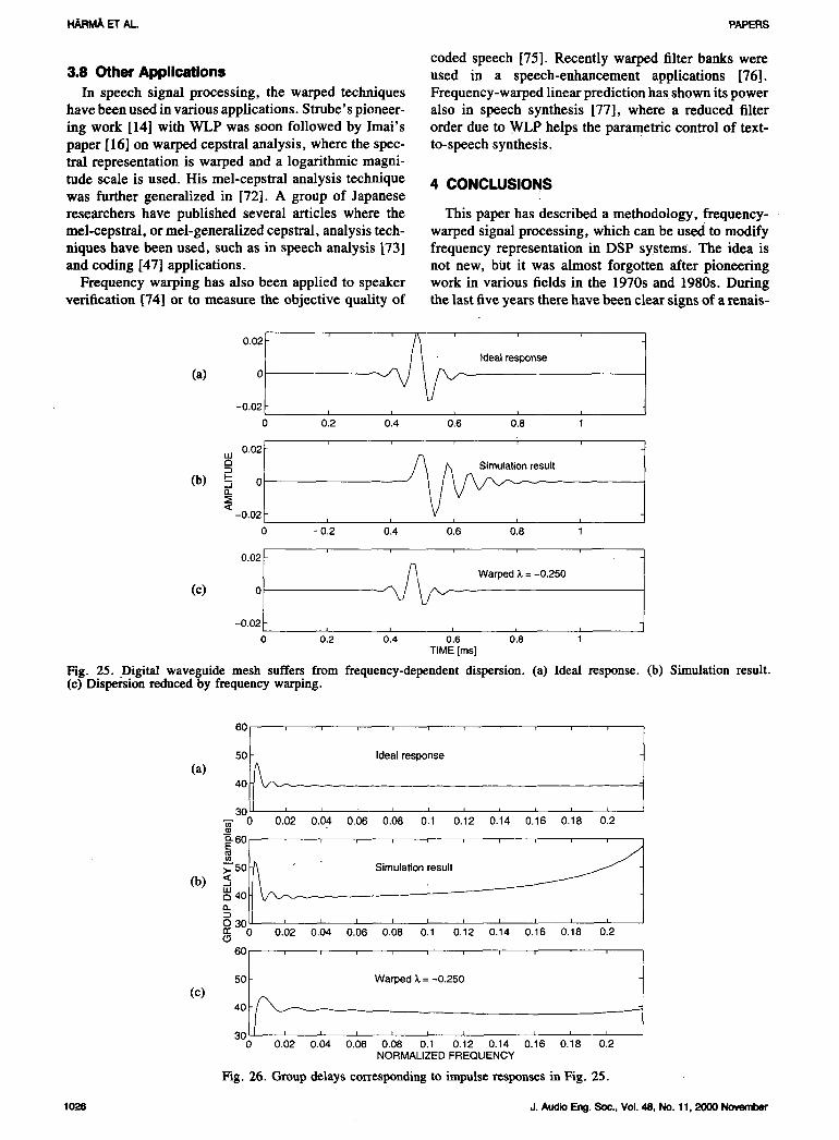
We present results from a simulation of an ideal square mum error on the same frequency band is only 0.60%membrane with rigid boundaries using the digital wave- [70], [68].guide mesh. For details of the simulation, see [71], [70], Our example demonstrates the fact that frequency[68]. Fig. 25(a) shows a waveform propagating in the warping turns the digital waveguide mesh simulationsdiagonal direction in the original digital waveguide into an accurate method for obtaining impulse responsesmesh. Note that this is the ideal response, since there of acoustic systems. However, a suitable waveguideis no dispersion in that case. mesh algorithm needs to be used as well, that is, either
The waveform in Fig. 25(b) has been obtained with the interpolated rectangular mesh or the triangular mesh.
|0 .... i
-10
-30_ IIR modeling order: 20
-40.......................102 103 104
10........
_,, 0
-10
(b) _-20
-30 .... , ........ , ...... _ .,-40102 10 3 104
Frequency (Hz)
Fig. 24. Example of modeling minimum-phase dummy-headHRTFs using warped IIR filters: (a) filter order 20. (b) order 6.(--) originalHRTF magnituderesponse. ( .... ) IIR model using Prony's method. (-----) warpedI1Rmodel using Prony's method-(warping coefficient 0.65). Warped IIR models have been unwarpedto second-ordersections to retain the same computationalcomplexity as linear designs.
J. Audio Eng.Soc., Vol. 48, No. 11, 2000 November 1025
I-_RMA ET AL. PAPERS
coded speech [75]. Recently warped filter banks were3.8 Other Applications used in a speech-enhancement applications [76].
In speech signal processing, the warped techniques Frequency-warped linear prediction has shown its powerhave been used in various applications. Strube'spioneer- also in speech synthesis [77], where a reduced filter
ing work [14] with WLP was soon followed by Imai's order due to WLP helps the parametric control of text-paper [16] on warped cepstral analysis, where the spec- to-speech synthesis.tral representation is warped and a logarithmic magni-
tude scale is used. His mel-cepstral analysis technique 4 CONCLUSIONSwas further generalized in [72]. A group of Japaneseresearchers have published several articles where the This paper has described a methodology, frequeney-mel-eepstral, or mel-generalized cepstral, analysis tech- warped signal processing, which can be used to modifyniques have been used, such as in speech analysis [73] frequency representation in DSP systems. The idea isand coding [47] applications, not new, but it was almost forgotten after pioneering
Frequency warping has also been applied to speaker work in various fields in the 1970s and 1980s. Duringverification [74] or to measure the objective quality of the last five years there have been clear signs of a renais-
00:i Ideal response
(a)
-0.02 _-0 0'2 0'4 06 0'8 ;
a n result
(b)Q-
< -0.02_ , , ,0 -0'.2 0.4 0.6 0.8 ;
(C) 0"011 ' _ Warped Z = -0.250-0.02 _-0 0'2 04 0'6 0'8
TIME [ms]
Fig. 25. Digital waveguide mesh suffers from frequency-dependent dispersion. (a) Ideal response. (b) Simulation result.(e) Dispersion reduced by frequency warping.
60 i , i i i i i i i
(a) 50 t/_ Ideal response
401_3O t I I I I I I I
0 0.02 0.04 0.06 0.08 0.1 0.12 0.14 0.16 0.18 0.2
6°1°......... S/_. 5011_ Simulation result
a4ollII
II , , , i , , , , ,30rr 0 0.02 0.04 0.06 0.08 0.1 0.12 0.14 0.16 0.18 0.2'(9
60/ ..........
(C) 50I, _ Warped _,=-0.250
40 I/ __ _______.--t I I I I I I300 0.02 0.04 0.06 0.08 0.1 0.12 0.14 0.16 0.18 0.2
NORMALIZED FREQUENCY
Fig. 26. Group delays corresponding to impulse responses in Fig. 25.
1026 J. AudioEng. Soc., Vol. 48, No. 11, 2000 November
PAPERS SIGNALPROCESSINGFORAUDIOAPPLICATIONS
sance for this methodology. J. Acoust. Soc. Am., vol. 87, pp. 2592-2605. (1990It has been shown that practically any DSP algorithm June).
can be warped. After presenting the basic methodology, [5] B. C. J. Moore, "Frequency Analysis and Mask-it was shown how this can be utilized in filter design and ing," in Hearing Handbook of Perception and Cogni-implementation, nonparametric and parametric spectral tion, 2rid ed., B. C. J. Moore, Ed. (Academic Press,estimation, coding, several audio applications, and in a New York, 1995).specific application to reduce errors that are produced [6] R. D. Patterson, "Auditory Filter Shapes Derivedby a multidimensional discrete-time structure, with Noise Stimuli," J. Acoust. Soc. Am., vol. 59, pp.
The main focus has been on audio and wide-band 640-654 (1976 Mar.).
speech signal-processing techniques, where it is advan- [7] A. Sek and B. C. J. Moore, "The Critical Modula-tageous to design the system so that it takes into account tion Frequency and Its Relationship to Auditory Filteringthe nonuniform frequency resolution of human hearing, at Low Frequencies," J. Acoust. Soc. Am., vol. 93, pp.It is shown that a warped DSP system can be designed 2606-2615 (1994 May).to approximate accurately the frequency resolution of [8] E. Zwicker and H. Fastl, Psychoacoustics: Factshearing. In several application examples this brings and Models (Springer-Verlag, Berlin, 1990).about obvious gains in terms of quality, computational [9] A. V. Oppenheim, D. H. Johnson, and K. Steig-complexity, and digital storage. It seems obvious that litz, "Computation of Spectra with Unequal Resolutionother variations of the methodology can be discovered Using the Fast Fourier Transform," Proc. IEEE, vol.and new applications can be found. 59, pp. 299-301 (1971 Feb.).
[10] A. V. Oppenbeim and D. H. Johnson, "Discrete
5 ACKNOWLEDGMENT Representation of Signals," Proc. IEEE, vol. 60, pp.681-691 (1972 June).
The work of Aki Hanna has been supported by the [11] C. Braccini and A. V. Oppenheim, "UnequalAcademy of Finland and the GETA graduate school. Bandwidth Spectral Analysis Using Digital FrequencyThe work of Vesa Vilim_iki has been supported by the Warping," IEEE Trans. Acoust., Speech, Signal Pro-Academy of Finland. cess., vol. ASSP-22, pp. 233-245 (1974 Aug.).
[12] W. Sch0ssler, "Variable Digital Filters," Arch.
6 REFERENCES Elek. Obertragung, vol. 24, pp. 524-525 (1970), re-printed in Digital Signal Processing, L. Rabiner and
[1] S. S. Stevens, J. Volkmann, and E. B. Newman, C.M. Rader, Eds. (Selected Reprint Series, IEEE Press,"A Scale for the Measurement of the Psychological Mag- New York, 1972).nitude of Pitch," J. Acoust. Soc. Am., vol. 8, pp. [13] A. G. Constantinides, "Spectral Transforma-185-190 (1937). tions for Digital Filters," Proc. IEEE, vol. 117, pp.
[2] B. Scharf, "Critical Bands," in Foundations of 1585-1590 (1970 Aug.).Modern Auditory Theory, J. V. Tobias, Ed. (Academic [14] H. W. Strube, "Linear Prediction on a Warpedpress, New York, 1970), pp. 159-202. Frequency Scale," J. Acoust. Soc. Am., vol. 68, pp.
[3] B. C. J. Moore, R. W. Peters, and B. R. Glasberg, 1071-1076 (1980 Oct.)."Auditory Filter Shapes at Low Center Frequencies," J. [15] E. Kriiger and H. W. Strube, "Linear PredictionAcoust. Soc. Am., vol. 88, pp. 132-140 (1990 July). on a Warped Frequency Scale," IEEE Trans. Acoust.
[4] D. D. Greenwood, "A Cochlear Frequency- Speech, Signal Process., vol. 36, pp. 1529-1531Position Function for Several Species--29 Years Later," (1988 Sept.).
• / 'l I ' b d I ' II I I'1 I 4 I I r
50 : ' ' ' I
(a) 00 0.05 0.1 0.15 0.2 0.25
t,n
(b) _/_5°t _: i ', ', ', ','', :', ', ',O_ 0.05 0.1 0.15 0.2 0.25
i i i i _ _l t II _ I I I I
I I I p I [ I I II I I I I I
(c) ' 'I I
I I II I II I I I I I
00 0.05 0.1 0.15 0.2 0.25
NORMALIZED FREQUENCY
Fig. 27. Simulated magnitude responses of ideal square membrane. (a) Original digital waveguide mesh. (b) Interpolatedmesh.(c) Warped inteq_lated mesh (X = -0.327358). Dashed vertical lines-analytically solved ideal eige_le frequencies.
J. Audio Eng. Soc., Vol. 48, No. 11, 2000 November 1027
HARM._ETAL. PAPERS
[16] S. Imai, "Cepstral Analysis Synthesis on the Mel poo, Finland, 1996 Sept.), pp. 483-486.Frequency Scale," in Proc. IEEE Int. Conf., on Acous- [35] M. R. Schroeder, B. S. Atal, and J. L. Hall,tics, Speech, and Signal Processing (Boston, MA, 1983 "Optimizing Digital Speech Coders by Exploiting Mask-Apr.), pp. 93-96. ing Properties of the Human Ear," J. Acoust. Soc. Am.,
[17] U. K. Laine, "Famlet, to Be or Not to Be a vol. 66, pp. 1647-1652 (1979 Dec.).Wavelet," in Proc. Int. Symp. Time-Frequency and [36] U. K. Laine, "Critically Sampled PRFilterbanksTime-Scale Analysis (Victoria, Canada, 1992 Oct.). of Nonuniform Resolution Based on Block ReeursiveIEEE, pp. 335-338. FAMlet Transform," in Proc. EUROSPEECH'97 (Rhodes,
[18] U. K. Laine, M. Karjalainen, and T. A!tosaar, Greece, 1997 Sept.), vol. 2, pp. 697-700."WLP in Speech and Audio Processing," in Proc. IEEE [37] G. Evangelista and S. Cavaliere, "Discrete Fre-
Int. Conf. on Acoustics, Speech, and Signal Processing quency Warped Wavelets: Theory and Applications,"(Adelaide, Australia, 1994), vol. 3, pp. 349-352. IEEE Trans. Signal Process., vol. 46, pp: 874-885
[19] J. O. Smith and J. S. Abel, "Bark and ERB (1998 Apr.).Bilinear Transform," IEEE Trans. Speech and Audio [38] N. S. Jayant and P. Noll, Digital Coding ofProcess., vol. 7, pp. 697-708 (1999 Nov.). Waveforms (Prentice-Hall, Englewood Cliffs, NJ, 1984).
[20] R. E. King and P. N. Paraskevopoulos, "Digital [39] N. Iwakami and T. Moriya, "Transform-Domain
Laguerre Filters," J. Circuit Theory Appl., vol. 5, pp. Weighted Interleave Vector Quantization (TwinVQ),"81-91 (1977). presented at the 101stConventionof the Audio Engi-
[21] B. Maione and B. Turchiano, "Laguerre z- neering Society, J. Audio Eng. Soc. (Abstracts), vol.Transfer Function Representation of Linear Discrete- 44, pp. 1171, 1172 (1996 Dec.), preprint 4377.Time Systems," Int. J. Contr., vol. 41, pp. 245-257 [40] J. Makhoul and M. Berouti, "Adaptive Noise(1985). Spectral Shaping and Entropy Coding in Predictive Cod-
[22] B. Wahlberg, "System Identification Using La- ing of Speech," IEEE Trans. Acoust., Speech, Signalguerre Models," IEEE Trans. Automatic Contr., vol. Process., vol. ASSP-27, pp. 63-73 (1979 Feb.).36, pp. 551-562 (1991 May). [41] J. D. Markel and A. H. Gray, Linear Prediction
[23] T. Oliveira e Silva, "Optimality Conditions for of Speech, vol. 12 of Communication and CyberneticsTruncated Laguerre Networks," 1EEE Trans. Signal (Springer, New York, 1976).Process., vol. 42, pp. 2528-2530 (1995). [42] P. Noll, "On Predictive Quantizing Schemes,"
[24] J. G. Proakis and D. G. Manolakis, Digital Sig- Bell Sys. Tech. J., vol. 57, pp. 1499-1532 (1978hal Processing, 2nd ed. (Macmillan, New York, 1992). May-June).
[25] A. H_irm_i, "Implementation of Recursive Filters [43] J. Gibson, "Adaptive Prediction in Speech Dif-Having Delay Free Loops," in Proc. IEEE Int. Conf. ferential Encoding Systems," Proc. IEEE, vol. 68, pp.on Acoustics, Speech, and Signal Processing (Seattle, 488-525 (1980 Apr.).WA, 1998 May), vol. 3, pp. 1261-1264. [44] T. Barnwell, "Recursive Autocorrelation Com-
[26] A. Hhrm/i, "Implementation of Frequency- putation for LPC Analysis," in Proc. IEEE Int. Conf.Warped Recursive Filters," Signal Process., vol. 80, on Acoustics, Speech, and Signal Processing (Hartford,pp. 543-548 (2000 Feb.). CT, 1977 May), pp. 1-4.
[27] T. Kobayashi, S. Imai, and Y. Fukuda, "Mel- [45] A. HLrrnii, "Evaluation of a Warped Linear Pre-Generalized Log Spectral Approximation Filter," Trans. dictive Coding Scheme," in Proc. IEEE Int. Conf. onIECE, vol. 68, pp. 610-611 (1985). Acoustics, Speech, and Signal Processing (Istanbul,
[28] M. Karjalainen, A. H_irm_i,J. Huopaniemi, and Turkey, 2000 June), vol. 2, pp. 897-900.U. K. Laine, "Warped Filters and Their Audio Applica- [46] L. R. Rabiner and R. W. Schafer, Digital Pro-tions,"inlEEE Workshop on Appl. Signal Proc. Acoust. cessing of Speech Signals (Prentice-Hall, Englewoodand Audio (New Paltz, NY, 1997 Oct.). Cliffs, NJ, 1978).
[29] T. W. Parks and C. S. Burrus, Digital Filter [47] K. Koishida, K. Tokuda, T. Kobayashi, and S.Design (Wiley, New York, 1987). Imai, "CELP Coding System Based on Mel-Generalized
[30] L. B. Jackson, Digital Filters and Signal Pro- Cepstral Analysis," in Proc. Int. Conf. on Spoken Lan-cessing, 2nd ed. (Kluwer, Boston, MA, 1989). guage Processing (Philadelphia, PA, 1996 Oct.), vol. 1.
[31] M. Karjalainen, E. Piirilii, A. J_rvinen, and J. [48] A. C. Den Brinker, "Adaptive Modified La-Huopaniemi,"ComparisonofLoudspeakerEqualization guerre Filters," Signal Process., vol. 31, pp. 69-79Methods Based on DSP Techniques," J. Audio Eng. (1993).Soc., vol. 47, pp. 14-31 (1999 Jan./Feb.). [49] K. Tokuda, T. Kobayashi, S. Imai, and T. Fu-
[32] The Mathworks, Natick, M_A, USA, MATLAB-- kada, "Speech Coding Based on Adaptive Mel-CepstralThe Language for Technical Computing (1997 Jan.). Analysis and Its Evaluation," Elec. and Comm. in Ja-
[33] U. K. Laine and A. Harrn_i, "On the Design of pan, pt. 3, vol. 78, no. 6, pp. 50-61 (1995).Bark-FAMlet Filterbanks," in Proc. Nordic Acoust. Mtg. [50] Z. Fejzo and H. Lev-Ari, "Adaptive Laguerre-(NAM) (Helsinki, Finland, !996 June), pp. 277-284. Lattice Filters," IEEE Trans. Signal Process., vol. 45,
[34] M. Karjalainen, A. H_irmii, and U. K. Laine, pp. 3006-3016 (1997 Dec.)."Realizable Warped IIR Filter Structures," in Proc. [51] A. H_irmii, U. K. Laine, and M. Karjalainen,IEEE Nordic Signal Process. Symp., NORSIG 96 (Es- "Backward Adaptive Warped Lattice for Wideband
1028 J.AudioEng.Soc.,Vol.48,No.11,2000November
PAPERS SIGNALPROCESSINGFORAUDIOAPPLICATIONS
Stereo Coding," in Signal Processing IX: Theories and logna, Italy, 1995 Nov.), pp. 27-30.Applications, EUSIPCO'98 (Rhodes, Greece, 1998 [65] S. VanDuyneandJ. O. Smith,"The3DTetrahe-Sept.), EURASIP, pp. 729-732. dral Digital Waveguide Mesh with Musical Appliea-
[52] J. A. Moorer, "The Manifold Joys of Conformal tions," in Proc. Int. Computer Music Conf. (ICMC'96)
Mapping: Applications to Digital Filtering in the Stu- (Hong Kong, 1996 Aug.), pp. 9-16.din," J. Audio Eng. Soc., vol. 31, pp. 826-841 (1983 [66] F. Fontana and D. Rocchesso, "Physical Model-Nov.). ingof Membranesfor PercussionInstruments,"Acustica
[53] D. K. Wise, "A Survey of Biquad Filter Struc- (with Acta Acustica), vol. 84, pp. 529-542 (1998tures for Application to Digital Parametric Equaliza- May/June).tion," presented at the 105th Convention of the Audio [67] L. Savioja and V. Viilimiiki, "Improved Discrete-Engineering Society, J. Audio Eng. Soc. (Abstracts), Time Modeling of Multi-Dimensional Wave Propaga-vol. 46, p. 1041 (1998 Dec.), preprint 4820. tion Using the Interpolated Digital Waveguide Mesh,"
[54] C. Asavathiratham, P. E. Beckmann, and in Proc. Int. Conf. on Acoustics, Speech, and SignalA. V. Oppenheim, "Frequency Warping in the Design Processing (ICASSP'97) (Munich, Germany, 1997and Implementation of Fixed-Point Audio Equalizers," Apr.), vol. 1, pp. 459-462.in Proc. IEEE Workshop on Appl. Signal Proc. Audio [68] L. Savioja and V. Viilimiiki, "Reducing the Dis-and Acoust. (New Paltz, NY, 1999 Oct.), IEEE, pp. persioii Error in the Digital Waveguide Mesh Using In-55-59. terpolation and Frequency-Warped Techniques," IEEE
[55] M. Tyril, J. A. Pedersen, and P. Rubak, "Digital Trans. Speech Audio Process., voi. 8, pp. 184-194Filters for Low-Frequency Equalization," presented at (2000 Mar.).the 106th Convention of the Audio Engineering Society, - [69] T. I. Laakso, V. Viilim_iki, M. Karjalainen, andJ. Audio Eng. Soc. (Abstracts), vol. 47, p. 519 (1999 U.K. Laine, "Splitting the Unit Delay--Tools for Frac-June), preprint 4897. tional Delay Filter Design," IEEE Signal Process. Mag.,
[56] M. Karjalainen, "Warped Filter Design for the vol. 13, pp. 30-60 (1996 Jan.).Body Modeling and Sound Synthesis of String Instru- [70] L. Savioja and V. Viilimiiki, "Reduction of thements," in Proc. Nordic Acoustical Mtg. (NAM'96) Dispersion Error in the Triangular Digital Waveguide
(Helsinki, Finland, 1996 June), pp. 445-453. Mesh Using Frequency Warping," IEEE Signal Process.[57] M. Karjalainen and J. O. Smith, "Body Model- Lett., vol. 6, pp. 58-60 (1999 Mar.).
ing Techniques for String Instrument Synthesis," in [71] L. Savioja and V. V_ilim_iki, "Reduction of theProc. Int. Computer Music Conf. (Hong Kong, 1996 Dispersion Error in the Interpolated Digital WaveguideAug.), pp. 232-239. Mesh Using Frequency Warping," in Proc. Int. Conf. on
[58] J. Huopaniemi, N. Zacharov, and M. Karja- Acoustics, Speech, and SignalProcessing (ICASSP'99)lainen, "Objective and Subjective Evaluation of Head- (Phoenix, AZ, 1999 Mar.), vol. 2, pp. 973-976.Related TransferFunctionFilterDesign,"J. Audio Eng. [72] K. Tokuda, T. Kobayashi, S. Imai, and T.Soc., vol. 47, pp. 218-239 (1999Apr.). Chiba, "Spectral Estimation of Speech by Mel-
[59] J. Huopaniemi and M. Karjalainen, "Review of Generalized Cepstral Analysis," Elec. and Comm. inDigital Filter Design and Implementation Methods for Japan, pt. 3, vol. 76, pp. 30-43 (1993).3-D Sound," presented at the 102nd Convention of the [73] T. Kobayashi and S. Imai, "Spectral AnalysisAudio Engineering Society, J. Audio Eng. Soc. (Ab- Using Generalized Cepstrum," IEEE Trans. Acoust.,stracts), vol. 45, p. 413 (1997 May), preprint 4461. Speech, Signal Process. , vol. ASSP-32, pp. 1087-1089
[60] J. Huopaniemi, "Virtual Acoustics and 3-D (1984 Oct.).Sound in Multimedia Signal Processing," Ph.D. thesis, [74] H. Noda, "Frequency-Warped Spectral DistanceHelsinki University of Technology, Laboratory of Measures for Speaker Verification in Noise," in Proc.Acoustics and Audio Signal Processing (1999). IEEE Int. Conf. on Acoustics, Speech, and Signal Pro-
[61] J. M. Jot, O. Warusfel, and V. Larcher, "Digital cessing (New York, NY, 1988 Apr.), pp. 576-579.Signal Processing Issues in the Context of Binaural and [75] S. Wang, A. Sekey, and A. Gersho, "AuditoryTransaural Stereophony," presented at the 98th Convention Distortion Measure for Speech Coding," in Proc. IEEEof the Audio Engineering Society, J. Audio Eng. Soc. Int. Conf. on Acoustics, Speech, and Signal Processing(Abstracts), vol. 43, p. 396 (1995 May), preprint 3980. (Toronto, Ont., Canada, 1991 May), vol. 1, pp. 493-
[62] S. Van Duyne and J. O. Smith, "Physical Model- 496.ing with the 2-D Digital Waveguide Mesh," in Proc. [76] B. Krzysztof and A. P. Alexander, "Speech En-Int. Computer Music Conf. (ICMC'93) (Tokyo, Japan, hancement System for Hands-Free Telephone Based on1993 Sept.), pp. 40-47. the Psychoacoustically Motivated Filter Bank with All-
[63] L. Savioja, T. Rinne, and T. Takala, "Simula- pass Frequency Transformation," in Proc. EurosPeech'99tion of Room Acoustics with a 3-D Finite Difference (Budapest, Hungary, 1999 Sept.), vol. 6, pp. 2555-2558.Mesh," in Proc. Int. Computer Music Conf. (ICMC'94) [77] M. Karjalainen, T. Altosaar, and M. Vainio,(Aarhus, Denmark, 1994 Sept.), pp. 463-466. "Speech Synthesis Using Warped Linear Prediction and
[64] F. Fontana and D. Rocchesso, "A New Formula- Neural Networks," in Proc. IEEE Int. Conf. on Acous-tion of the 2D-Waveguide Mesh for Percussion Instru- tics, Speech, and Signal Processing (Seattle, WA,meats," in Proc. XI Coll. on Musical lnformatics (Bo- 1998), vol. 2, pp. 877-880.
J.AudioEng.Soc.,Vol.48,No.11,2000November 1029
HARMAETAL. PAPERS
THE AUTHORS
[]
A. Harm_i M. Karjalainen L. Savioja
V. V_ilimaki U.K. Laine J. Huopaniemi
Aki Harmi was born in Oulu, Finland, in 1969. He Association, the International Computer Music Associa-received the Master's and Licentiate's degrees in electri- tion, the European Speech Communication Association,cal engineering from the Helsinki University of Technol- and several Finnish scientific and engineering societies.ogy, Espoo, Finland, in 1997 and 1999, respectively. •Currently he is a Ph.D. student in the Laboratory ofAcoustics and Audio Signal Processing, Helsinki Uni- Lauri Savioja was born in Turku, Finland, in 1966.versity of Technology. His research interests are mainly He studied computer science and acoustics and receivedin audio signal processing and auditory modeling. His the degrees of Master of Science in Technology (1991),lnternet home page is http://www.acoustics.hut.fi/_aqi/. Licentiate of Science in Technology (1995), and Doctor
of Science in Technology (1999) from the Department of• Computer Science, Helsinki University of Technology,
Matti Karjalainen was born in Hankasalmi, Finland, Espoo, Finland. Currently he works at the Laboratoryin 1946, He received the M.Sc. and Dr.Tech. degrees of Telecommunications Software and Multimedia at thein electrical engineering from the Tampere University of university. His research interests include virtual reality,Technology in 1970 and 1978, respectively. His doctoral room acoustics, and physical modeling of musicalthesis dealt with speech synthe§is by rule in Finnish. instruments.
From 1980 he was an associate professor and since Dr. Savioja is a member of the Audio Engineering1986 he has been a full professor in acoustics and audio Society and the Acoustical Society of Finland. His homesignal processing at the Helsinki University of Technol- page is http://www.tml.hut.f/_las/.ogy on the faculty of electrical engineering. In audio •technology his interest is in audio signal processing,such as DSP for sound reproduction, perceptually based Vesa Valimaki was born in Kuorevesi, Finland, insignal processing, as well as music DSP and sound syn- 1968. He studied acoustics and digital signal processingthesis. In addition to audio DSP his research activities at Helsinki University of Technology, Espoo, Finland,cover speech synthesis, analysis, and recognition, per- and received the Master of Science in Technology, Li-eeptual auditory modeling, spatial hearing, DSP hard- centiate of Science in Technology, and Doctor of Sci-ware, software, and programming environments, as well ence in Technology degrees in electrical engineering inas various branches of acoustics, including musical 1992, 1994, and 1995, respectively. His doctoral thesisacoustics and modeling of musical instruments. He has dealt with sound synthesis based on physical modeling.written 250 scientific and engineering articles and con- He has worked at the HUT Laboratory of Acousticstributed to organizing several conferences and work- and Audio Signal Processing since 1990. In 1996 heshops, recently serving as the papers chairman of the spent six months as a postdoctoral research fellow atAES 16th International Conference on Spatial Sound the University of Westminster, London, UK. He thenReproduction. returned to HUT, where he holds the position of senior
Dr. Karjalainen is an ALES fellow and a member of assistant (equivalent to assistant professor). He is cur-the Institute of Electrical and Electronics Engineers, the rently on leave as a postdoctoral researcher under a grantAcoustical Society of America, the European Acoustics from the Academy of Finland. In 1999 he was appointed
1030 J:AudioEng.Soc.,Vol.48, No.11,2000November
PAPERS SIGNALPROCESSINGFORAUDIOAPPLICATIONS
Docent in Audio Signal Processing at HUT. He teaches multimedia, and information technology at Helsinkiaudio signal processing at HUT and also lectures on University of Technology and received the M. Sc., Lic.digital signal processing at the Centre for Music and Tech., and D. Sc. (Tech.)degrees in electrical and com-Technology, Sibelius Academy, Helsinki, Finland. His munications engineering in 1995, 1997, and 1999, re-research interests are in the fields of musical signal pro- spectively. His doctoral thesis was on the topic of virtualcessing, active noise control, and digital filter design, acoustics and 3-D audio.
Dr. Valimaki is a senior member of the IEEE Signal He worked as research scientist at the Laboratory ofProcessing Society and a member of the AES, the Inter- Acoustics and Audio Signal Processing of HUT fromnational Computer Music Association, the Acoustical 1993 until 1998. In 1998 he was a visiting scholar at theSociety of Finland, and the Finnish Musicological Soci- Center for Computer Research in Music and Acousticsety. His home page is http://www.acoustics.hut.fi/ (CCRMA) at Stanford University, Stanford, CA. Since_vpv/, and his e-mail address is [email protected]. 1998 he has been Research Manager at Nokia Research
Center's Speech and Audio Systems Laboratory in Hel-• sinki, Finland. His professional interests include 3-D
Unto K. Laine was born in Kannus, Finland. He re- sound and interactive audio, virtual audiovisual environ-ceived the M.S. (Eng.) degree from Tampere University ments, digital audio signal processing, psychoacoustics,of Technology in 1972 and the degree of Lic. Tech. room acoustics, musical acoustics, audio content analy-in 1979. During 1981-1983 he worked as a visiting sis and processing, and multimedia. He is author orresearcher at the Speech Transmission Laboratory, coauthor of over 40 technical papers published in inter-KTH, Stockholm, Sweden. Since 1983 he has worked national journals and conferences, and he has been ac-as a researcher and lecturer at the Laboratory of Acous- tively involved in the MPEG-4 and MPEG-7 standardi-tics and Audio Signal Processing, HUT, Espoo, Fin- zation work.land. He wrote his doctoral thesis in 1989 at HUT. In Dr. Huopaniemi is a member of the AES and was1990 he received a position and degree of docent at the secretary and committee member of the AES FinnishLaboratory of Acoustics and Audio Signal Processing Section from 1994 to 1998. He was secretary of thewhere he has been holding a permanent position of se- AES 16th International Conference on Spatial Soundnlor scientist since 1995. Reproduction, held in Finland in 1999. For this contri-
Dr. Lalne is a member of AES. bution he received an AES Citation in September 1999.He is a member of the AES Technical Committee on
• Multichannel and Binaural Technologies. He is also aJyri Huop_niemi was born in Helsinki, Finland, in member of the Institute of Electrical and Electronics
1968. He studied acoustics and audio signal processing, Engineers and the Acoustical Society of Finland.
J.AudioEng.Soc.,Vol.48,No.11,2000November 1031