Embed Size (px)
Citation preview
2013 SHOW ISSUE/3-D TECHNOLOGY
Official Monthly Publication of the Society for Information Display • www.informationdisplay.orgMay/June 2013Vol. 29, No. 3
May-June Cover_SID Cover 4/11/2013 7:52 PM Page 1

Radiant Zemax pC2_Layout 1 4/20/2013 8:29 PM Page C2
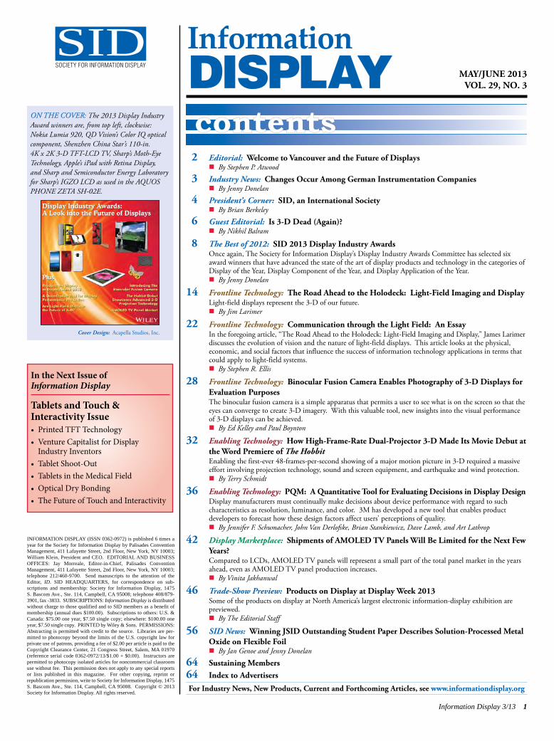
2 Editorial: Welcome to Vancouver and the Future of Displaysn By Stephen P. Atwood
3 Industry News: Changes Occur Among German Instrumentation Companiesn By Jenny Donelan
4 President’s Corner: SID, an International Societyn By Brian Berkeley
6 Guest Editorial: Is 3-D Dead (Again)?n By Nikhil Balram
8 The Best of 2012: SID 2013 Display Industry AwardsOnce again, The Society for Information Display’s Display Industry Awards Committee has selected sixaward winners that have advanced the state of the art of display products and technology in the categories ofDisplay of the Year, Display Component of the Year, and Display Application of the Year. n By Jenny Donelan
14 Frontline Technology: The Road Ahead to the Holodeck: Light-Field Imaging and DisplayLight-field displays represent the 3-D of our future.n By Jim Larimer
22 Frontline Technology: Communication through the Light Field: An EssayIn the foregoing article, “The Road Ahead to the Holodeck: Light-Field Imaging and Display,” James Larimer discusses the evolution of vision and the nature of light-field displays. This article looks at the physical, economic, and social factors that influence the success of information technology applications in terms thatcould apply to light-field systems. n By Stephen R. Ellis
28 Frontline Technology: Binocular Fusion Camera Enables Photography of 3-D Displays forEvaluation PurposesThe binocular fusion camera is a simple apparatus that permits a user to see what is on the screen so that theeyes can converge to create 3-D imagery. With this valuable tool, new insights into the visual performanceof 3-D displays can be achieved.n By Ed Kelley and Paul Boynton
32 Enabling Technology: How High-Frame-Rate Dual-Projector 3-D Made Its Movie Debut atthe Word Premiere of The HobbitEnabling the first-ever 48-frames-per-second showing of a major motion picture in 3-D required a massiveeffort involving projection technology, sound and screen equipment, and earthquake and wind protection. n By Terry Schmidt
36 Enabling Technology: PQM: A Quantitative Tool for Evaluating Decisions in Display DesignDisplay manufacturers must continually make decisions about device performance with regard to such characteristics as resolution, luminance, and color. 3M has developed a new tool that enables product developers to forecast how these design factors affect users’ perceptions of quality.n By Jennifer F. Schumacher, John Van Derlofske, Brian Stankiewicz, Dave Lamb, and Art Lathrop
42 Display Marketplace: Shipments of AMOLED TV Panels Will Be Limited for the Next FewYears?Compared to LCDs, AMOLED TV panels will represent a small part of the total panel market in the yearsahead, even as AMOLED TV panel production increases. n By Vinita Jakhanwal
46 Trade-Show Preview: Products on Display at Display Week 2013Some of the products on display at North America’s largest electronic information-display exhibition are previewed.n By The Editorial Staff
56 SID News: Winning JSID Outstanding Student Paper Describes Solution-Processed MetalOxide on Flexible Foiln By Jan Genoe and Jenny Donelan
64 Sustaining Members64 Index to Advertisers
Information Display 3/13 1
MAY/JUNE 2013VOL. 29, NO. 3
InformationDISPLAYcontents
For Industry News, New Products, Current and Forthcoming Articles, see www.informationdisplay.org
INFORMATION DISPLAY (ISSN 0362-0972) is published 6 times ayear for the Society for Information Display by Palisades ConventionManagement, 411 Lafayette Street, 2nd Floor, New York, NY 10003;William Klein, President and CEO. EDITORIAL AND BUSINESSOFFICES: Jay Morreale, Editor-in-Chief, Palisades ConventionManagement, 411 Lafayette Street, 2nd Floor, New York, NY 10003;telephone 212/460-9700. Send manuscripts to the attention of theEditor, ID. SID HEADQUARTERS, for correspondence on sub-scriptions and membership: Society for Information Display, 1475 S. Bascom Ave., Ste. 114, Campbell, CA 95008; telephone 408/879-3901, fax -3833. SUB SCRIP TIONS: Information Display is distributedwithout charge to those qualified and to SID members as a benefit ofmembership (annual dues $100.00). Subscriptions to others: U.S. &Canada: $75.00 one year, $7.50 single copy; elsewhere: $100.00 oneyear, $7.50 single copy. PRINTED by Wiley & Sons. PERMISSIONS:Abstracting is permitted with credit to the source. Libraries are per-mitted to photocopy beyond the limits of the U.S. copyright law forprivate use of patrons, providing a fee of $2.00 per article is paid to theCopyright Clearance Center, 21 Congress Street, Salem, MA 01970(reference serial code 0362-0972/13/$1.00 + $0.00). Instruc tors arepermitted to photocopy isolated articles for noncommercial classroomuse without fee. This permission does not apply to any special reportsor lists published in this magazine. For other copying, reprint orrepublication permission, write to Society for Information Display, 1475S. Bascom Ave., Ste. 114, Campbell, CA 95008. Copy right © 2013Society for Information Display. All rights reserved.
In the Next Issue ofInformation Display
Tablets and Touch &Interactivity Issue• Printed TFT Technology• Venture Capitalist for Display Industry Inventors
• Tablet Shoot-Out• Tablets in the Medical Field• Optical Dry Bonding• The Future of Touch and Interactivity
SIDSOCIETY FOR INFORMATION DISPLAY
2013 SHOW ISSUE/3-D TECHNOLOGY
Official Monthly Publication of the Society for Information Display • www.informationdisplay.orgMay/June 2013Vol. 29, No. 3
May-June Cover_SID Cover 4/11/2013 7:52 PM Page 1
Cover Design: Acapella Studios, Inc.
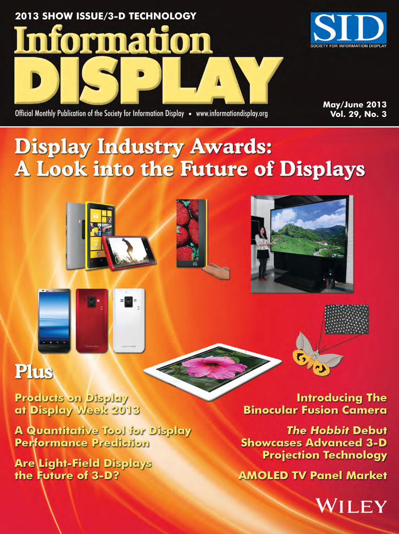
ON THE COVER: The 2013 Display IndustryAward winners are, from top left, clockwise:Nokia Lumia 920, QD Vision’s Color IQ opticalcomponent, Shenzhen China Star’s 110-in. 4K x 2K 3-D TFT-LCD TV, Sharp’s Moth-EyeTechnology, Apple’s iPad with Retina Display, and Sharp and Semiconductor Energy Laboratoryfor Sharp’s IGZO LCD as used in the AQUOSPHONE ZETA SH-02E.
ID TOC p1_Layout 1 4/20/2013 10:52 PM Page 1
Welcome to Vancouver and the Future ofDisplays
by Stephen Atwood
Welcome to Vancouver, British Columbia, for our 50thannual Display Week event. It feels like it was just yester-day when we were all in Boston for the last Symposium andExhibition – not to mention the Market Focus Conferences,Business Conference, Investors Conference, Seminars, andthe many other great happenings that are organized each
year for your benefit and enjoyment. This year we’re back on the West Coast of NorthAmerica, in Canada for the first time. Vancouver is known to be a great destinationcity and one that promises lots of options for great food, sightseeing, and relaxingaway from the demands of the office. This year also continues our year-long celebration of the birth of SID, founded in
September of 1962 by a small group of visionary people on the campus of the Universityof California in Los Angeles. The next year, 1963, marked the first annual SID Symposium, which quickly grew into the highly acclaimed Display Week program wehave today. Now, 50 years later, it’s amazing to see how much the Society hasachieved and all that has happened in this time. Over the past year, we celebrated ouranniversary with an outstanding one-day conference and banquet at UCLA organizedby Larry Tannas and his fellow members of the SID LA Chapter. As a veteran of Display Week myself for more years than I choose to count, I
strongly encourage you to look beyond the world-class exhibition and consider every-thing going on during the week, including more than 400 paper presentations, shortcourses, seminars, the aforementioned conferences, the keynote addresses, the Honors& Awards dinner, and more. Now, take my advice: Getting the most out of your Display Week experience involves some serious planning. Take time to review thefull program and mark off the things that are most important to you. Plan your days to see as many things as you can and coordinate with colleagues to make sure the stuffyou cannot see is covered by others. Usually, there are dozens of presentations andexhibits that I know I want to attend, but I also find many surprises that I can only discover if I explore as much as possible. This issue of ID can be particularly useful for your planning because it features our
“Products on Display” coverage, which is assembled each year by our staff to help youget the most out of the exhibition. Also, as we do every year, we’ve invited a presti-gious team of freelance technology enthusiasts to report on all the happenings in theirsubject areas, and they will be hard at work covering everything they can. We’ll havedaily blog updates on the newly redesigned ID web site (www.informationdisplay.org)and a full issue of post-show coverage later in the year. If you have a question aboutanything on the exhibit floor, just email us at [email protected] and we’ll get your question to the right reporter to see what we can find out.Our cover story this month announces the recipients of the SID 2013 Display Industry
Awards (for products that shipped in 2012). Each year the committee recognizes themost innovative display products and technologies from the wide array of nominationsreceived. If you are around on Wednesday, consider making plans to attend the annualawards luncheon and see the winning companies receive their awards.Our issue lineup continues this month with three Frontline Technology articles
exploring the future of 3-D displays, beginning with author Jim Larimer, a human
2 Information Display 3/13
Executive Editor: Stephen P. Atwood617/306-9729, [email protected]
Editor-in-Chief: Jay Morreale212/46 0-9700, [email protected]
Managing Editor: Jenny Donelan603/924-9628, [email protected]
Advertising Sales Manager: Joseph Tomaszewski201-748-8895, [email protected]
Advertising Sales Representative: Roland Espinosa201-748-6819, [email protected]
Editorial Advisory BoardStephen P. Atwood, Chair
Azonix Corp., U.S.A.Helge Seetzen
TandemLaunch Technologies, Westmont, Quebec,Canada
Allan KmetzConsultant, U.S.A.
Larry WeberConsultant, U.S.A.
Guest EditorsMaterials
Ion Bita, Qualcomm MEMS TechnologiesOLEDs
Ho-Kyoon Chung, Sungkyunkwan UniversityOxide TFTs
Arokia Nathan, University of Cambridge3D Trends
Nikhil Balram, Ricoh InnovationsTouch and Interactivity
Geoff Walker, Intel Corp. e-Paper and Tablets
Russel Martin, Qualcomm MEMS Technologies Lighting
Sven Murano, Novaled AG Novel Displays
Brian Schowengerdt, University of Washington Very-High-Resolution Displays
David Trczinski, Avid Digital Signage
Terry Schmidt, Christie Digital SystemsAlan Koebel, Christie Digital Systems
Contributing EditorsAlfred Poor, ConsultantSteve Sechrist, ConsultantPaul Semenza, NPD DisplaySearchJason Heikenfeld, University of Cincinnati
InformationDISPLAY
The opinions expressed in editorials, columns, and feature articles do not necessarily reflect the opinions ofthe Executive Editor or Publisher of Information DisplayMagazine, nor do they necessarily reflect the position ofthe Society for Information Display.
editorial
(continued on page 58)
ID Editorial Issue3 p2,58_Layout 1 4/20/2013 8:32 PM Page 2
Changes Occur Among GermanInstrumentation CompaniesLate last year, instrumentation companies aroundthe world began consolidating at the speed oflight, or so it seemed if you happened to be following the announcements. Most of the action occurred in Germany. In December 2012, KonicaMinolta Optics (KMOP) in Japan announced thatit had bought Instrument Systems, a lighting, LED,and display metrology company with facilities inMunich and Berlin, for an undisclosed sum. InJanuary 2013, Instrument Systems disclosed thatit had purchased all development and productionrights from autronic–Melchers in the previousyear. autronic–Melchers is a display measurementsystems company formerly based in Karlsruhe,Germany. And in March, photometric test equip-ment maker Optronik Berlin announced that it hadmerged with parent company Instrument Systems.In making the above moves, Instrument Systems,
already an instrumentation leader, was seeking toexpand its range of products into the measurementof lighting devices (that’s why Optronik, with itsproduct range of goniometers, was acquired) andto expand its expertise and range of products inthe area of measuring displays, which it did byacquiring the IP of autronic–Melchers’ DMS andConoScope series of instruments). KMOP, in turn, had begun reorganizing its
optical businesses with the aim of evolving from a supplier of parts and components to limitedindustrial sectors into a group of business unitsfocusing on growth markets. The company’srecent acquisition of Instrument Systems shouldmake KMOP a “power house” in the instrumenta-tion industry, according to an e-mail interviewwith an industry source based in Germany.Germany is still a power house on its own
when it comes to instrumentation. The light andcolor measurement industry in this country has arich history. Existing key companies includeLMT Lichtmesstechnik Berlin GmbH, X-Rite(which had already acquired Optronik GmbH,retaining the color measurement IP and selling the light measurement part to Instrument Systems), BYK-Gardner, and, of course, Instrument Systems/KMOP. In terms of ongoing operations, Instrument
Systems, which employs 131 people and hasR&D, production, and sales facilities in Munichand Berlin, will retain its own brand following themerger. Existing president and CEO RichardDistl, who started Instrument Systems 26 yearsago, will remain with the company. autronic-Melchers GmbH has closed its operations in Karlsruhe. The Optronik location in Berlin willbe retained, with all the employees working as ateam of experts specializing in goniophotometry and in equipping turnkey photometric laboratories.
– Jenny Donelan
industry news Architects of World ClassDisplay EnhancementsEuropTec USA is a specialist in glass processing and fabrication for the display industry. As an expert in various �nishing and processing technologies, we design and manufacture products for display applications.
PRODUCT & CAPABILITIES:® ™
APPLICATIONS:
EuropTec Ad 2013.indd 1 1/9/13 2:53 PM
See Us at Display Week 2013, Booth 715
Industry News Issue3 p3_Layout 1 4/20/2013 7:22 PM Page 3
SID, an International Society
by Brian BerkeleyPresident, Society for Information Display
Greetings and a warm welcome to all to Display Week2013! As of this writing, final preparations are under wayin earnest as SID heads to Vancouver, British Columbia, for its annual Display Week event. This year will mark the50th meeting of Display Week, and it is the first time that it
has been held outside of the United States. Considering that SID is very much aninternational society, it is fitting that Display Week be held at an international location.In fact, well over half of SID’s membership is based outside of the U.S.Vancouver was selected as the venue for Display Week 2013 for many reasons. It is
a beautiful city that is well known for its diversity and international demographic.Less than half of its residents are native English speakers. Vancouver is accessible,with many daily non-stop flights from major cities throughout Asia, Europe, and theU.S. The most recent Winter Olympics, certainly an international event, were held inVancouver. The conference center (or using local vernacular, “centre”) where DisplayWeek 2013 will be held has frequently received the #1 rating among all worldwideconference venues.As is the case every year, Display Week 2013 promises to reveal many exciting
technical developments in the field of information display. There are reports that verylarge 4K × 2K displays will be shown, and some as large as 110 inches will bereported in the technical sessions. Full high definition (FHD, or 1920 × 1080) resolution, which not too many years ago became available on TV-sized displays, cannow fit in the palm of one’s hand – driving pixel densities to well over the 400 ppilevel in mainstream mobile devices that will ship this year. These and many other significant developments will be reported and shown at Display Week 2013. TheInnovation Zone, or I-Zone for short, made its first appearance on the exhibit floor lastyear, and more emerging prototypes will be shown in this second year for the I-Zone.Display Week 2013 will certainly be ground-breaking and informative.SID became an international society in 1976, when the Japan Chapter was officially
instated. As of now, 17 of SID’s 28 chapters are based outside of the U.S., and amajority of SID’s student branches are also located outside of North America. Overtime, as SID has broadened its reach to become a truly worldwide society, it hasembraced a wide swath of cultural and style differences. It is probably not surprisingthat only two of SID’s eight Executive Committee members are native English speakers.As one of the “two,” I can relate to international immersion from personal experience,having lived in Korea for 8 out of the last 10 years. It was challenging and humblingto communicate in a very different language, to work in unfamiliar ways, and toaccept many other differences. But it was also a rewarding life experience. Manytimes, I had to say, which roughly means, “please say itagain slowly.” The experience taught me, when using English, to be just a little morepatient and tolerant when communicating with non-native English speakers, and to tryto explain things using the simplest possible terms and to stick to the essential points.SID certainly is no stranger to international events. Although this year is the first
for Display Week to be held outside of the U.S., in 2013 alone, SID is also sponsoringor co-sponsoring major events in Shanghai, Belgium, Korea, Taipei, London, Brazil,and Japan (in order). To increase worldwide access to the conference proceedings,
4 Information Display 3/13
president’s corner
(continued on page 60)
SID EXECUTIVE COMMITTEEPresident: B. BerkeleyPresident-Elect: A. GhoshRegional VP, Americas: D. EcclesRegional VP, Asia: B. WangRegional VP, Europe: J. RaspTreasurer: Y. S. KimSecretary: H. SeetzenPast President: M. Anandan
DIRECTORSBangalore: T. RuckmongathenBay Area: J. PollackBeijing: X. YanBelarus: V. A. VyssotskiCanada: T. C. SchmidtDayton: D. G. HopperDelaware Valley: J. W. Parker IIIDetroit: J. KanickiFrance: J-P. ParneixHong Kong: H. LeungIndia: G. RajeswaranIsrael: G. GolanJapan: K. KondohKorea: K.-W. WhangLatin America: A. MammanaLos Angeles: L. TannasMid-Atlantic: J. KymissisMid-Europe: H. De SmetNew England: S. AtwoodPacific Northwest: A. AbileahRussia: I. N. KompanetsSingapore: X. W. SunSouthwest: S. O’RourkeTaipei: J. ChenTexas: Z. YanivU.K. & Ireland: S. DayUkraine: V. SerganUpper Mid-West: B. Bahadur
COMMITTEE CHAIRS50th Anniversary: L. TannasAcademic: P. BosArchives: R. DonofrioAudit: S. O’RourkeBylaws: T. LoweChapter Formation – Europe: H. De SmetConventions: P. DrzaicConventions – Europe: I. SageDefinitions & Standards: T. FiskeDisplay Industry Awards: R. MelcherHonors & Awards: F. LuoI-Zone: J. KanickiInvestment: Y. S. KimLong-Range Planning: A. GhoshMembership: H.-S. KwokNominating: A. AnandanPublications: H. SeetzenSenior Member Grade: A. GhoshWeb Site: H. SeetzenWeb Activities: L. Palmateer
CHAPTER CHAIRSBangalore: S. SambadamBay Area: G. WalkerBeijing: N. XuBelarus: A. SmirnovCanada: A. KitaiDayton: J. C. ByrdDelaware Valley: J. BlakeDetroit: S. PalvaFrance: J. P. ParneixHong Kong: M. WongIndia: S. KauraIsrael: I. Ben DavidJapan: K. KondoKorea: Y. S. KimLatin America: V. MammanaLos Angeles: P. Joujon-RocheMid-Atlantic: G. MelnikMid-Europe: H. J. LempNew England: J. GandhiPacific Northwest: K. YugawaRussia: V. BelyaevSingapore/Malaysia: C. C. ChaoSouthwest: M. StrnadTaipei: C. C. WuTexas: R. FinkU.K. & Ireland: M. JonesUkraine: V. SorokinUpper Mid-West: P. Downen
SOCIETY FOR INFORMATION DISPLAY1475 S. Bascom Ave., Ste. 114, Campbell, CA 95008408/879-3901, fax -3833 e-mail: [email protected]://www.sid.org
28
29
language, to work in unfamiliar ways, and to accept many other differences. But it was also a rewarding life experience. 30 Many times, I had to say, “ ,” which roughly means, “please say it again slowly.” The experience 31 taught me, when using English, to be just a little more patient and tolerant when communicating with non-native English 32 speakers, and to try to explain things using the simplest possible terms and to stick to the essential points. 33
34
35 We look forward to seeing you in Vancouver. Welcome! ! 36
37
38
Presidents Corner Issue3_Layout 1 4/20/2013 7:24 PM Page 4
LCD GLASS RESIZING SERVICE FOR INDUSTRY WORLDWIDELLiicceennssoorr // PPrroopprriieettoorr,, Orange, California, USAContact: Larry Tannas, PHONE: 1 714 633 7874, CELL: 1 714 342 [email protected], www.tannas.com
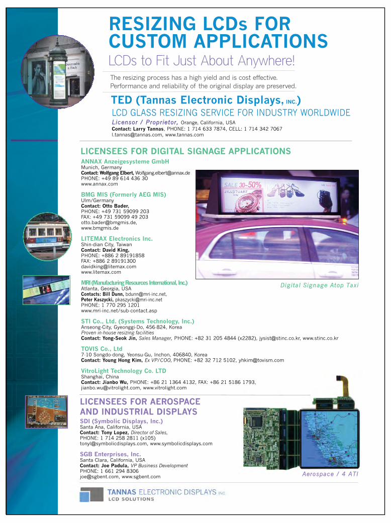
RESIZING LCDs FOR CUSTOM APPLICATIONSLCDs to Fit Just About Anywhere!
DDiiggiittaall SSiiggnnaaggee AAttoopp TTaaxxii
LICENSEES FOR AEROSPACE AND INDUSTRIAL DISPLAYS
LICENSEES FOR DIGITAL SIGNAGE APPLICATIONS
The resizing process has a high yield and is cost effective. Performance and reliability of the original display are preserved.
AAeerroossppaaccee // 44 AATTII
TED (Tannas Electronic Displays, INC.)
SDI (Symbolic Displays, Inc.)Santa Ana, California, USAContact: Tony Lopez, Director of Sales, PHONE: 1 714 258 2811 (x105)[email protected], www.symbolicdisplays.com
SGB Enterprises, Inc.Santa Clara, California, USAContact: Joe Padula, VP Business DevelopmentPHONE: 1 661 294 [email protected], www.sgbent.com
ANNAX Anzeigesysteme GmbHMunich, GermanyContact: Wolfgang Elbert, [email protected]: +49 89 614 436 30www.annax.com
BMG MIS (Formerly AEG MIS)Ulm/GermanyContact: Otto Bader, PHONE: +49 731 59099 203FAX: +49 731 59099 49 [email protected], www.bmgmis.de
LITEMAX Electronics Inc.Shin-dian City, TaiwanContact: David King, PHONE: +886 2 89191858FAX: +886 2 [email protected]
MRI (Manufacturing Resources International, Inc.)Atlanta, Georgia, USAContacts: Bill Dunn, [email protected],Peter Kaszycki, [email protected]: 1 770 295 1201www.mri-inc.net/sub-contact.asp
STI Co., Ltd. (Systems Technology, Inc.)Anseong-City, Gyeonggi-Do, 456-824, KoreaProven in-house resizing facilities Contact: Yong-Seok Jin, Sales Manager, PHONE: +82 31 205 4844 (x2282), [email protected], www.stinc.co.kr
TOVIS Co., Ltd7-10 Songdo-dong, Yeonsu-Gu, Inchon, 406840, KoreaContact: Young Hong Kim, Ex VP/COO, PHONE: +82 32 712 5102, [email protected]
VitroLight Technology Co. LTDShanghai, ChinaContact: Jianbo Wu, PHONE: +86 21 1364 4132, FAX: +86 21 5186 1793, [email protected], www.vitrolight.com
Tannas p5_Layout 1 4/20/2013 7:31 PM Page 5
Is 3-D Dead (Again)?
by Nikhil Balram
This is the question that came to mind for many attendees at the 2013 Consumer Electronics Show (CES) in Januaryin Las Vegas. As usual, there were lots of interesting newconsumer gadgets, with a special emphasis on networkedand mobile ones. TVs were again a prominently featureditem. But the main storylines for TVs were the connectivity
and intelligence, and the step up to 4K resolution. A first-time visitor could easilythink she was back in the pre-Avatar period of 2008 or earlier, when the big futurethemes were connectivity, smartness, and higher resolution.The reality is that the second big coming, the “Renaissance” after the “Golden Age”
of the 1950s, of stereoscopic 3-D (S3D) was probably overhyped in the euphoriaaround James Cameron’s Avatar. Other factors were the film industry’s need to raiseticket prices as an antidote to the shorter big screen life of movies, piracy, and othercompetitors for the consumer’s time, as well as the always-urgent need of the consumer-electronics market for “the next big thing” to drive sales. One can reasonably argue that S3D has settled into a steady state in which it is one
of the options that certain segments of cinema and home viewers appreciate and seekout, while others ignore. A very big difference from the 1950s is that S3D today rideson top of the overall trend of adoption of digital technologies in cinema – from pro-duction to display – so even a modest adoption by consumers can make the economicswork. However, as technologists and vision scientists, we (the experts) recognizeanother very important factor at work here – the S3D that is available today is funda-mentally limited and flawed, and these limitations and flaws play a large role in thediminished interest that consumers are showing.The work of well-known vision-science researchers like Professor Martin Banks at
UC Berkeley has shown very clearly and conclusively that stereoscopic 3-D has somebasic limitations. The most fundamental and arguably most important one is the so-called vergence-accommodation conflict created by the presentation of stereoscopic 3-D on the flat, single-plane screens used in cinema and home today. The July 2008issue of Information Display has two articles – “Consequences of Incorrect FocusCues in Stereo Displays” by Banks et al. and “Scanned Voxel Displays” bySchowengerdt et al. that explain the issue and provide insights into possible solutions.This fundamental conflict is caused by the fact that presentation of stereoscopicimages on a single plane results in an unnatural decoupling of vergence (the point atwhich a person’s eyes converge) and accommodation (the point at which the eyesfocus), in contrast to real-world viewing where these two are always closely coupled.This conflict has been shown to cause viewer discomfort that manifests itself in different ways such as nausea, headaches, and tiredness. The film industry has responded by moderating the amount of depth that is
produced in S3D movies – the so-called “gentle 3-D”. In particular, this approachavoids putting objects of interest (i.e., objects the audience should be looking at) farbehind or far in front of the screen. As a consequence, objects of interest are moved tothe screen. This has reduced the possibility of viewer discomfort. But it has caused adifferent issue – a growing criticism from viewers that the 3-D effects are under-whelming and not worth the extra cost or inconvenience of wearing glasses. It isinteresting to see letters to the editor in traditional home theater magazines in which
6 Information Display 3/13
guest editorial
(continued on page 60)
J O I N S I DWe invite you to join SID to participate in shaping the futuredevelopment of:
• Display technologies and display-related products
• Materials and components for displays and display applications
• Manufacturing processes and equipment
• New markets and applications
In every specialty you will find SIDmembers as leading contributors totheir profession.
http://www.sid.org/Membership.aspx
VISITINFORMATION
DISPLAY ON-LINEFor daily display
industry news
www.informationdisplay.org
Submit Your News ReleasesPlease send all press releases and new prod-uct announcements to:
Jenny DonelanInformation Display Magazine411 Lafayette Street, Suite 201
New York, NY 10003Fax: 212.460.5460
e-mail: [email protected]
ID Guest Editorial Issue3 p6,60_Layout 1 4/20/2013 8:47 PM Page 6
See Us at Display Week 2013, Booth #821
*EMD is an affiliate of Merck KGaA, Darmstadt, Germany. In North America Merck operates under the name EMD
The Perfect PixelYou can‘t see us. But you see the difference.
Besides market-leading liquid crystals, EMD’s product range for displays comprises reactive mesogens for 3D displays as well as materials for OLEDs and organic electronics. Our anti-fingerprint coatings and phosphors for LEDs bring out the best picture quality on your display. State-of-the art display materials, a long history of expertise in their interaction and much-needed closeness to our part-ners in the display industry are the best conditions for perfect
display performance. Natural presentation of moving pictures, very high contrast and lower energy consumption are still to-day’s biggest challenges in the display industry. With our innovative new display materials we can push the limits even further and open the doors to unprecedented dis-play performance. The Perfect Pixel powered by EMD makes the difference.
www.emd4displays.com
Merck EMD.indd 1 4/21/2013 6:50:12 PM

See Us at Display Week 2013, Booth #821
www.merck4displays.com
The Perfect PixelYou don’t see Merck. But you see the difference.
Besides market-leading liquid crystals, Merck’s product range for displays comprises reactive mesogens for 3D displays as well as materials for OLEDs and organic electronics. Our anti-fingerprint coatings and phosphors for LEDs bring out the best picture quality on your display. State-of-the art display materials, a long history of expertise in their interaction and much-needed closeness to our part-ners in the display industry are the best conditions for perfect
display performance. Natural presentation of moving pictures, very high contrast and lower energy consumption are still today’s biggest challenges in the display industry. With our innovative new display materials we can push the limits even further and open the doors to unprecedented display performance. The Perfect Pixel powered by Merck makes the difference.
Merck Europe p7.indd 1 4/21/2013 7:00:34 PM
THIS YEAR’S Display Industry Awardwinners (products that were commerciallyavailable in 2012) particularly exemplify theidea that it’s what’s inside that counts. Every-one knows that we judge the quality of displays primarily by what we see (thoughinteractivity has become important as well).Yet, this year’s achievements are character-ized as much by what you don’t see thatmakes them better displays.
A case in point is Sharp and SEL’s IGZOtechnology, in which oxide semiconductorshave been used to create a smartphone withexceptional battery life, high resolution, andtouch capability. The result is a quality display you can enjoy much longer withoutrunning for the nearest electrical outlet.Another winner from Sharp uses nanotech-nology inspired by the structure of a moth’seye to create a display that suppresses thereflection of ambient light and providesdeeper blacks. QD Vision’s light-emittingsemiconductor nanocrystal products enableLCDs to achieve wider color gamuts than everbefore. The Retina Display in Apple’s latestiPad manages to fit 3 million pixels into asmall area, producing a viewing experiencethat truly rivals printed paper and photo-graphs. Nokia’s Lumia 920 smartphone usesoverdriving to create a display that is justplain fast. You can’t actually see all the magic
behind these devices, but it vastly improvesthe experience of using them in myriad ways.
There is one winner this year that turnsheads even when it’s off (though we suggestyou turn it on): the 110-in. LCD TV fromShenzhen China Star Optoelectronics Company. As you can see in the photographof this TV later on in this article, it’s biggerthan the person standing next to it.
According to Display Industry AwardsChair Robert Melcher, “The 2013 SID DisplayIndustry Awards demonstrate the diversity ofgreat achievements over the past year, and theresults of ongoing investments into new R&Dactivities.”
One of the exciting aspects of the displayindustry is that the underlying technologykeeps evolving, even when we thought wemight have reached a plateau. Please join usin saluting this year’s inspiring Display IndustryAward winners.
Display of the YearThis award is granted for a display with noveland outstanding features such as new physicalor chemical effects, or a new addressingmethod.
Gold Award: Sharp and SemiconductorEnergy Laboratory for Sharp’s IGZO LCDas used in the AQUOS PHONE ZETA SH-02EThe scope of connected applications for hand-held devices is ever growing, as is the demandfor information devices such as smartphonesthat enable us to see an enormous amount of
rich content anytime, anywhere. The penaltywe pay for this great performance has tradi-tionally involved high-power demands andshort battery life. In an effort to alleviate theneed for this tradeoff, Sharp Corporation andSemiconductor Energy Laboratory (SEL)jointly developed a new IGZO technology thatimparts crystallinity in an oxide semiconductorcomposed of indium (In), gallium (Ga), andzinc (Zn). This IGZO enables a display withboth high resolution and ultra-low power con-sumption, characteristics that have in the pastneeded to be balanced against each other. Inaddition, the IGZO incorporates a touch panel,and represents the first time an IGZO panelhas been integrated into a smartphone.
Sharp and SEL succeeded in aligning thecrystallizing IGZO layer in the c-axial direc-tion, which results in higher reliability of thedevice, in addition to enabling higher defini-tion, lower power consumption (1/5–1/10),and high performance of the touch panel dueto miniaturization and high performance ofthe thin-film transistor. The AQUOS PHONEZETA SH-02E from Sharp can be used for 2 days without charging batteries because ofits low power consumption and can be used4.8 times longer than conventional units whendisplaying a static image, thanks to the IGZO.Improved recognition accuracy and responsespeed of the touch panel enable a better userinterface as well. Pen input is also supported.
IGZO can also be applied to other, largerdisplays such as monitors, TVs, etc., since itcorresponds to the same manufacturing
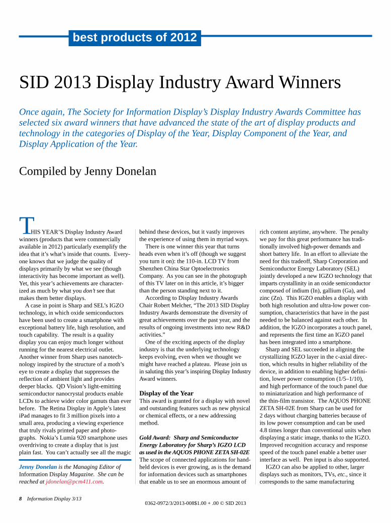
SID 2013 Display Industry Award WinnersOnce again, The Society for Information Display’s Display Industry Awards Committee hasselected six award winners that have advanced the state of the art of display products andtechnology in the categories of Display of the Year, Display Component of the Year, and Display Application of the Year.
Compiled by Jenny Donelan
Jenny Donelan is the Managing Editor ofInformation Display Magazine. She can bereached at [email protected].
8 Information Display 3/130362-0972/3/2013-008$1.00 + .00 © SID 2013
best products of 2012
Donelan DIA p8-12_Layout 1 4/20/2013 9:23 PM Page 8
processes of large motherglass substratesequivalent to a-Si. It can also be applied todisplays other than LCDs; for example,organic electroluminescent displays. IGZOwill also enable development of applicationsfor non-display uses such as sensing devices.Sharp and SEL researchers believe that IGZOwill become the core technology of displaysin the future.
Silver Award: Shenzhen China Star’s 110-in. 4K x 2K 3-D TFT-LCD TV Shenzhen China Star Optoelectronics Tech-nology Co., Ltd. (CSOT ) has successfullydeveloped a 110-in. LCD TV that is thelargest of its kind in the world. The 110-in.TFT-LCD integrates many innovations inLCD technology. It has a reported dynamicratio of 50000:1, an ultra-high brightness of1000 nits while consuming less than 1100 W,and highly saturated color reproduction with acolor gamut of about 92% of NTSC. More-over, through the effective use of shutterglasses technology in 3-D mode, the left toright eye crosstalk ratio is less than 2.5%.
CSOT’s goal was to develop an attractivedisplay with an extraordinary visual qualitythat would enable entertainment applications
such as gaming, movie, and multi-user com-munication. Such a TV will play an importantrole in bringing families together. Accord-ingly, the company wanted to develop a TVwith a large LCD panel, high resolution, and3-D functionality.
The 110-in. LCD was designed and fabri-cated in CSOT’s Gen 8.5 facility. To meet theabove visual reality and entertainmentrequirements, 4K × 2K resolution (3840 ×2160) and shutter glasses 3-D functionalitywere implemented. During development, themajor challenges were panel uniformity,power consumption, visual quality, and thecreation of an electric and optical andmechanical (OM) system for the ultra-high-definition LCD.
It is well-known that large-sized LCDs cansuffer from a lack of panel uniformity whenresolution and frame rate are upgraded forplaying films or pictures. In order to suppressmura and to enhance panel uniformity, CSOTimproved its manufacturing processes in several ways. High transmittance technology,high transmittance vertical alignment (HVA),and local dimming with a 288-area LED back-light were utilized to reduce power dissipa-tion. To support the 3-D mode with 120 Hz,
fine stereo performance (FSP) technology wasimplemented in the driving system, which greatly improved both 2-D and3-D quality. Since the ultra-high-definitioninterface is not mature in the market, theimage-process system was assembled with anFPGA-base unit by CSOT. This 110-in. panelcan receive any format of 4K × 2K video andis compatible with commercial transmissioninterfaces such as HDMI and DP. In addition,the large-sized panel accommodates the entireviewing angle of the human eye.
Besides the TV application, this 110-in.TFT-LCD can be used for advertisements andeducational and office displays. Another areaof focus for the company is to replace theLED boards commonly found in public-information-display (PID) systems with amuch more colorful, complex, and detailedmessaging medium afforded by this newdevelopment.
Display Component of the YearThis award is granted for a novel componentthat has significantly enhanced the perform-ance of a display. A component is sold as aseparate part destined to be incorporated intoa display. A component may also include
Information Display 3/13 9
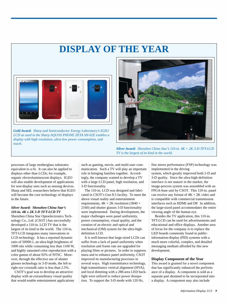
DISPLAY OF THE YEAR
Gold Award: Sharp and Semiconductor Energy Laboratory’s IGZOLCD as used in the Sharp AQUOS PHONE ZETA SH-02E enables adisplay with high resolution, ultra-low power consumption, andtouch.
Silver Award: Shenzhen China Star’s 110-in. 4K × 2K 3-D TFT-LCDTV is the largest of its kind in the world.
Donelan DIA p8-12_Layout 1 4/20/2013 9:23 PM Page 9
display-enhancing materials and/or parts fabricated with new processes.
Gold Award: QD Vision’s Color IQ OpticalComponentColor IQ optical components are advancedlight-emitting semiconductor nanocrystalproducts developed by QD Vision, Inc. Theyare the first product to utilize quantum dotsfor commercial displays. These breakthroughcomponents enable LCDs such as TVs, moni-tors, and all-in-one computers to achieve significantly wider color gamut with a farmore natural and vivid viewing experiencethan that of conventional white LED systems.
While most LCDs offer color quality thatmight reach 60–70% of the 1953 NTSC standard, LCD products utilizing ColorIQ optical components can achieve 100% ofthe NTSC, Adobe, and sRGB color perform-ance standards.
Designed as a drop-in solution, Color IQoptical components may be easily integratedinto conventional side-illumination LCDbacklight systems. The components are deliv-ered as a fully packaged, sealed solution,made of a glass optical tube containing redand green quantum dots (QDs) that are com-bined, tuned, and optimized to achieve a customer-specified on-screen white point.
Designed for very-high-volume LCD applica-tions, Color IQ products deliver color perform-ance meeting or exceeding that of OLED anddirect-lit RGB LED systems, while maintain-ing the cost structure of side-illumination systems for mainstream LCD TVs. After anumber of years in development, Color IQoptical components have been rigorouslyqualified and tested to meet the stringent product reliability and lifetime requirements of mainstream consumer-electronics applications.
Systems with Color IQ optical componentsuse highly efficient blue LEDs instead ofwhite LEDs as the excitation source that stim-ulates the optical component to emit red and
best products of 2012
10 Information Display 3/13
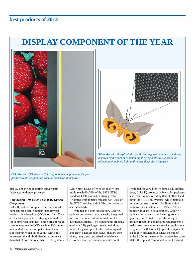
DISPLAY COMPONENT OF THE YEAR
Gold Award: QD Vision’s Color IQ optical component is the firstproduct to utilize quantum dots for commercial displays.
Silver Award: Sharp’s Moth-Eye Technology uses a nanoscale designinspired by the eyes of common night-flying moths to suppress thereflection of ambient light and realize deep black imagery.
Donelan DIA p8-12_Layout 1 4/20/2013 9:23 PM Page 10
green and transmit blue light. Color IQ optical components harness the unique light-emitting properties of a new class of nano-materials called quantum dots to emit narrowbandwidth light, which is ideal for LCD systems, delivering pure saturated colors tothe front of screen. QDs allow for independ-ent control of emission color and composition,with their nanoscale dimensions controllingthe semiconductor bandgap. Their combina-tion of efficiency, reliability, saturated emis-sion, and color tunability are unmatched inany known material set.
Sony is the first major TV manufacturer toincorporate Color IQ optical components intoa series of new 2013 model LCD televisions.
Silver Award: Sharp’s Moth-Eye TechnologySharp’s AQUOS Quattron 3D XL9 LCD TVsuse “moth-eye panels” to suppress the reflec-tion of ambient light and to realize deep blackimagery. Moth-Eye technology incorporates ananoscale design that is inspired by the eyesof the common night-flying moth. TheseMoth-Eye panels help to emphasize Sharp’s“four primary colors technology,” whichenhances the quality of color displays, andalso helps make imagery visible even in a
bright room. These sets (AQUOS Quattron3D, XL9 series, including 80-, 70-, 60-, 52-and 46-in. models) have a high contrast ratioto the level of 100 million:1 and images com-posed of approximately 8.3 million subpixels.
Sharp Corporation succeeded in the first-ever mass production of Moth-Eye technologyusing a nano-imprint process incorporating alarge-sized seamless drum stamper. In thefield of the optical films, low-reflective (LR)films coated monolayer-on and anti-reflective(AR) films deposited multi-layer-on are popu-lar. An LR film can be produced at a lowcost, but does not provide a sufficiently lowreflectance. An AR film can provide a lowreflectance, but entails high costs for produc-tion. Therefore, there are strong demands tomake both ends of optical properties and costsmeet. The Moth-Eye technology is a solutionbecause it has a single-layer film of UV curable acrylic resin on a base film, eventhough it works as a multi-layer film optically.A single-layer film has merits in terms ofmaterial and process costs. In the meantime,the drum stamper is also produced in a cost-effective and industrially easy way that utilizes a combination of anode oxidation andetching of aluminum. With this method,
100-nm-size structures are formed sponta-neously in a large area by merely controllinganode oxidation voltage, rather than by anoverly sensitive photolithography process thatmakes it difficult to achieve uniformity in alarge area.
The biggest benefit obtained by Moth-Eyetechnology is that it provides users with clearand high-quality images in bright places bothindoors and outdoors. In terms of power con-sumption, Moth-Eye technology can conserveelectricity with no loss of image quality sinceit is not necessary to increase the brightness ofthe backlight as much as you would with alower contrast panel. In the future, applica-tions for Moth-Eye need not be limited toelectronic displays. It can be used, for example, in the glass of a picture frame at amuseum or for a showcase at a jewelry shop.
Display Application of the YearThis award is granted for a novel and out-standing application of a display, where thedisplay itself is not necessarily a new device.
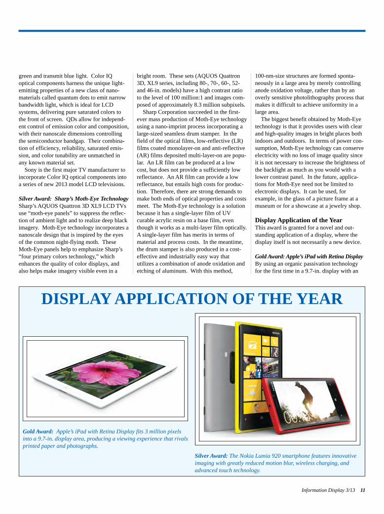
Gold Award: Apple’s iPad with Retina DisplayBy using an organic passivation technologyfor the first time in a 9.7-in. display with an
Information Display 3/13 11
DISPLAY APPLICATION OF THE YEAR
Gold Award: Apple’s iPad with Retina Display fits 3 million pixelsinto a 9.7-in. display area, producing a viewing experience that rivalsprinted paper and photographs.
Silver Award: The Nokia Lumia 920 smartphone features innovativeimaging with greatly reduced motion blur, wireless charging, andadvanced touch technology.
Donelan DIA p8-12_Layout 1 4/20/2013 9:23 PM Page 11
amorphous-silicon TFT, Apple engineers andtheir technology partners were able to fit fourtimes the number of pixels into the same 9.7-in. (diagonal) screen found on earlier iPadmodels. The resulting pixel density of theiPad Retina display – 264 ppi – makes textand graphics looks smooth and continuous atany size. This 2048 × 1536-pixel display has set a new standard for mobile-display resolution in a panel this size.
The third-generation iPad, as with eachiPad since the original, uses technology calledmobile in-plane switching (IPS) to achieve aviewing angle that has established the bench-mark in the tablet category. It enables users tohold the iPad in almost any position they wantand still see a high-fidelity image. The con-sistency of gamma over viewing angles provides an enhanced viewing experience toend users in consumer, business, and educa-tion applications; from web surfing, photo-
sharing, and gaming to medical research, business analysis, and elementary and higherlearning applications. The custom cell designis optimized for maximum transmittance,which, in combination with a custom driverIC and backlight, enables high resolution withindustry-leading low power consumption.
Silver Award: Nokia Lumia 920 The Nokia Lumia 920 smartphone is knownfor innovative imaging, wireless charging, andadvanced touch technology. The phone has aPureMotion HD+ screen that representsNokia’s latest innovation to radically improvedisplay capabilities. The PureMotion HD+4.5 in. 332-ppi screen offers crisper graphicsand less blurring while users are scrolling,navigating, and playing games. Nokia’s Pure-Motion technology addresses the inadequatemoving-image quality of other mobile displays, allowing it to better leverage the
high-speed rendering capabilities of its inter-nal graphics engine. One of the ways theNokia Lumia 920 prevents blur on a screen iswith a response time faster than 16.7 msec.On average, it takes about 9 msec for transi-tions on the screen of the Nokia Lumia 920.This phenomenal transition speed wasachieved by boosting the voltage to each LCDpixel – overdriving the panel. With overdrive-enhanced LC response, PureMotion displaypixels finish their transition well before theupdate of the next frame for any pixel needsto start, resulting in a less blurry image.
The Nokia Lumia 920 is the first Nokiasmartphone to have a super-sensitive touchdisplay that works with fingernails or evengloves. This new ability is the biggest leapforward for capacitive touch screens sincemulti-touch gestures were introduced. Thetechnology is adaptive, reacting to any con-ductive object that is touching the screen. Inpractice, the screen will automatically adjustsensitivity to provide the best possible touch-screen experience, making touch usage faster,more natural, and accurate. Super-sensitivedisplays have also been featured in otherNokia Lumia smartphones like the Lumia 720and 520.
The Nokia Lumia 920’s PureMotion display also introduces a new level of outdoorviewing experience in mobile displays. Inaddition to the very low reflectance, whichlargely improves dark tone rendering in ambi-ent light, PureMotion adds high luminancemode for backlight LED-driving and imagecontrast enhancement, on top of superb opti-cal stack design. Together they improve theoverall contrast and therefore sunlight read-ability. In an extremely bright environment,the Nokia Lumia 920 PureMotion displaytakes advantage of its backlight luminancereserve and becomes the smartphone WXGA(1280 × 768) display with highest peak lumi-nance. This high-luminance mode worksautomatically, based on the data received froman ambient-light sensor. n
best products of 2012
12 Information Display 3/13
For Industry News, New Products,Current and Forthcoming Articles,see www.informationdisplay.org
Donelan DIA p8-12_Layout 1 4/20/2013 9:23 PM Page 12
Discover the complete range of display measurement solutions.
From Instrument Systems, the light me-trology expert. We now offer the widest product range ever for characterizing and testing displays: spectroradiometers, imaging colorimeters, goniometer systems, conoscopes, and a broad range of accessories and software.www.instrumentsystems.com/display
Instrument Systems Germany · Phone: +49 89 45 49 43 0 · [email protected] · www.instrumentsystems.com
light measurement
NEW: Autronic-Melchers
product line
We measure quality.You display it.
Come and see us at
DISPLAY WEEK 2013
Booth No. 1120
DR_2023_Display_Anzeige_8-125_10-875 1 12.04.13 12:31Instrument Systems p13.indd 1 4/20/2013 9:33:09 PM
MODERN DISPLAYS can reconstruct2-D and stereo-pair 3-D (s3D) imagery, butsome important features of the natural visualenvironment are still missing; there remains avisible gap between natural imagery and itsreconstruction on even today’s most advanceddisplay technologies. This gap can be closedas light-field technologies replace our currentdisplay systems. The light field is all of theinformation contained in light as it passesthrough a finite volume in space as we look inany direction from a vantage point within thevolume. This article will describe the signalscontained in the light field and captured byhuman vision that are missing with 2-D, s3D,and multi-view s3D displays. To understandwhat is missing, it is useful to understand theevolutionary context of biological vision.
A Brief History of VisionBiological sensory systems evolved shortlyafter the Cambrian explosion, when predationbecame a part of life. Vision evolved so thatcreatures could find food and avoid beingeaten. Vision plays a central role in cognitionand our understanding of the world about us;it provides the basic information we use toorient in our immediate environment. Almost
all ideas have images as correlates; a chair is avisual pattern, a tiger is a large cat. Evenabstract concepts such as satisfaction can beimagined as a smile on a face. Visual cogni-tion, understanding images, is not the mentalequivalent of a photograph; our visual experi-ence is more akin to Plato’s concept of Idealsand Forms. We see people, objects, andactions — not their images as projected ontoour retinas.
Human vision is object oriented. We useinformation extracted from the light field andneural signal processing based upon learningand memory to understand the environmentwe sense from the images projected onto ourretinas. The image formed on the retina is theraw data for vision; it is not a sufficient signalfor image understanding by itself. To under-stand what we see, we change eye positionsand focus to de-clutter or segment a scene intowhole objects.
Not all of the information embedded in the light field is accessible to vision. Recon-structing information we cannot see is waste-ful, just as leaving out information we can seelimits the veridicality of the virtual scene weexperience on modern displays. Artists maywish to create non-veridical or distortedimagery in cinema and photography, but thisis a choice the artist should make and not havemade for them by the imaging technology.
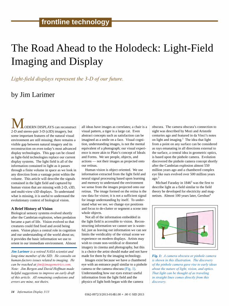
Images exist because we have a chamberedeye with an entrance pupil similar to a pinholecamera or the camera obscura (Fig. 1).Understanding how our eyes extract usefulinformation from the light field and thephysics of light both began with the camera
obscura. The camera obscura’s connection tosight was described by Mozi and Aristotlecenturies ago and featured in da Vinci’s noteson light and imaging.1 The idea that lightfrom a point on any surface can be consideredas rays emanating in all directions external tothe surface, a central idea in geometric optics,is based upon the pinhole camera. Evolutiondiscovered the pinhole camera concept shortlyafter the Cambrian explosion almost 550 million years ago and a chambered complexeye like ours evolved over 500 million yearsago.2
Michael Faraday in 18463 was the first todescribe light as a field similar to the fieldtheory he developed for electricity and mag-netism. Almost 100 years later, Gershun4
The Road Ahead to the Holodeck: Light-FieldImaging and DisplayLight-field displays represent the 3-D of our future.
by Jim Larimer
Jim Larimer is a retired NASA scientist andlong-time member of the SID. He consults onhuman-factors issues related to imaging. Hecan be reached at [email protected]: Jim Bergen and David Hoffman madehelpful suggestions to improve an early draftof this article. All remaining confusions anderrors are mine, not theirs.
14 Information Display 3/130362-0972/3/2013-014$1.00 + .00 © SID 2013
frontline technology
Fig. 1: A camera obscura or pinhole camerais shown in this illustration. The discovery of the pinhole camera gave rise to early ideasabout the nature of light, vision, and optics.That light can be thought of as traveling in straight lines comes directly from this discovery.
Larimer p14-20_Layout 1 4/20/2013 9:48 PM Page 14
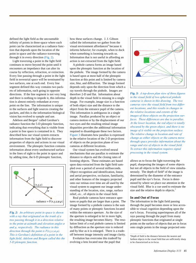
defined the light field as the uncountableinfinity of points in three-space where eachpoint can be characterized as a radiance func-tion that depends upon the location of thepoint in space and the radiance traversingthrough it in every direction (Fig. 2).
Light traversing a point in the light fieldcontinues to move beyond the point until itencounters an impedance that can alter itscourse by reflection, refraction, or extinction.Every line passing through a point in the lightfield in terrestrial space will be terminated bytwo surfaces, one at each end. Every line segment defined this way contains two pack-ets of information, each going in oppositedirections. If the line segment is not very longand there is nothing to impede it, this informa-tion is almost entirely redundant at everypoint on the line. The information is uniqueto the surfaces and light sources creating thepackets, and this is the information biologicalvision has evolved to sample and use.
Adelson and Bergen5 called Gershun’s radiance function the 5-D plenoptic function,indicating that everything that is visible froma point in free space is contained in it. Theydescribed how our visual system extractsinformation from the light field to discoverproperties of objects and actions in our visualenvironment. The plenoptic function containsinformation about every unobstructed surfacein the lines of sight to the point in space andby adding time, the 6-D plenoptic function,
how these surfaces change. J. J. Gibsoncalled the information we gather from thevisual environment affordances6 because itinforms behavior; for example, when to duckwhen something is looming towards us.Information that is not useful in affording anaction is not extracted from the light field.
A pinhole camera forms an image basedupon the plenoptic function at the location ofthe pinhole. The image formed by the camerais based upon at most half of the plenopticfunction at this point and is limited by camerasize, blur, and diffraction. The image formeddepends only upon the direction from which aray travels through the pinhole. Images aretherefore 2-D and flat. Information aboutdepth in the visual field is missing in a singleimage. For example, image size is a functionof both object size and the distance to theobject from the entrance pupil of the camera.This information is ambiguous in a singleimage. Parallax produced by an object orcamera motion or by the displacement of ourtwo eyes and the resulting retinal image disparities provides the additional informationrequired to disambiguate these two factors.Figure 3 illustrates how parallax is expressedin the relative location of the 2-D projectionsof objects on the projection plane of two cameras at different locations.
Our visual system has evolved neuralmechanisms that use parallax to estimate thedistance to objects and the closing rates oflooming objects. These estimates are basedupon data extracted from the light field sam-pled over a period of several milliseconds.Object recognition and identification, linearand aerial perspective, occlusion, familiarity,and other features of the imagery projectedonto our retinas over time are all used by thevisual system to augment our image under-standing of the location, size, range, surfacerelief, etc., of objects in the visual field.
Real pinhole cameras have entrance aper-tures or pupils that are larger than a point. The image formed by a pinhole camera is the sumof many points or plenoptic functions locatedwithin the entrance aperture. As the size ofthe aperture is enlarged to let in more light,the resulting image becomes blurry. The reso-lution limit of a real pinhole camera is limitedby diffraction as the aperture size is reducedand by blur as it is enlarged. There is a trade-off between image intensity and image clarity.
Evolution has overcome this tradeoff byevolving a lens located near the pupil that
allows us to focus the light traversing thepupil, sharpening the images of some objectsbut not all objects in the field of view simulta-neously. The depth of fielda of the image isdetermined by the diameter of the entrancepupil and the eye’s focus. Focus is deter-mined by where we place our attention in thevisual field. Blur is a cue used to estimate thesize and the relative depth to objects.7
In and Out of FocusThe information in the light field passingthrough the pupil becomes more or less acces-sible to visual cognition depending upon theeye’s focus. Focusing superimposes all of therays passing through the pupil from manyplenoptic functions that originated at single points on the surface of objects that are in focus onto single points in the image projected onto
Information Display 3/13 15
Fig. 3: A top-down plan view of three figuresin the visual field of two spherical pinholecameras is shown in this drawing. The twocameras view the visual field from two differ-ent locations, and this results in changes inthe relative locations and extents of theimages of these objects on the projection sur-faces. These differences are due to parallax.At the lower location, the red object is totallyobscured by the green object, and there is noimage of it visible on the projection surface.The relative change in location and rate ofchange as either objects or the camera movethrough space provides information about therange and size of objects in the visual field.To extract this information requires signalprocessing in the visual system.
Fig. 2: An arbitrary point in space is shownwith a ray that originated on the trunk of atree passing through it in a direction relativeto the point at azimuth and elevation angles øand µ, respectively. The radiance in thisdirection through the point is F(x,y,z,ø,µ).This is Gershun’s definition of a point in thelight field; Adelson and Bergen called this the5-D plenoptic function.
aDepth of field is the distance between the nearest and farthest objects in the visual field that are sufficiently sharpto be characterized as in-focus.
Larimer p14-20_Layout 1 4/20/2013 9:48 PM Page 15
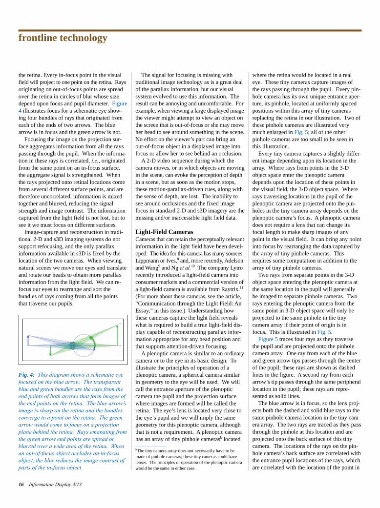
the retina. Every in-focus point in the visual field will project to one point on the retina. Rays originating on out-of-focus points are spreadover the retina in circles of blur whose sizedepend upon focus and pupil diameter. Figure4 illustrates focus for a schematic eye show-ing four bundles of rays that originated fromeach of the ends of two arrows. The bluearrow is in focus and the green arrow is not.
Focusing the image on the projection sur-face aggregates information from all the rayspassing through the pupil. When the informa-tion in these rays is correlated, i.e., originatedfrom the same point on an in-focus surface,the aggregate signal is strengthened. Whenthe rays projected onto retinal locations comefrom several different surface points, and aretherefore uncorrelated, information is mixedtogether and blurred, reducing the signalstrength and image contrast. The informationcaptured from the light field is not lost, but tosee it we must focus on different surfaces.
Image-capture and reconstruction in tradi-tional 2-D and s3D imaging systems do notsupport refocusing, and the only parallaxinformation available in s3D is fixed by thelocation of the two cameras. When viewingnatural scenes we move our eyes and translateand rotate our heads to obtain more parallaxinformation from the light field. We can re-focus our eyes to rearrange and sort the bundles of rays coming from all the pointsthat traverse our pupils.
The signal for focusing is missing with traditional image technology as is a great dealof the parallax information, but our visual system evolved to use this information. The result can be annoying and uncomfortable. For example, when viewing a large displayed image the viewer might attempt to view an object on the screen that is out-of-focus or she may move her head to see around something in the scene.No effort on the viewer’s part can bring anout-of-focus object in a displayed image intofocus or allow her to see behind an occlusion.
A 2-D video sequence during which thecamera moves, or in which objects are moving in the scene, can evoke the perception of depth in a scene, but as soon as the motion stops,these motion-parallax-driven cues, along withthe sense of depth, are lost. The inability tosee around occlusions and the fixed imagefocus in standard 2-D and s3D imagery are themissing and/or inaccessible light field data.
Light-Field CamerasCameras that can retain the perceptually relevant information in the light field have been devel-oped. The idea for this camera has many sources: Lippmann or Ives,8 and, more recently, Adelson and Wang9 and Ng et al.10 The company Lytro recently introduced a light-field camera into consumer markets and a commercial version of a light-field camera is available from Raytrix.11(For more about these cameras, see the article,“Communication through the Light Field: AnEssay,” in this issue.) Understanding howthese cameras capture the light field revealswhat is required to build a true light-field dis-play capable of reconstructing parallax infor-mation appropriate for any head position andthat supports attention-driven focusing.
A plenoptic camera is similar to an ordinarycamera or to the eye in its basic design. Toillustrate the principles of operation of aplenoptic camera, a spherical camera similarin geometry to the eye will be used. We willcall the entrance aperture of the plenopticcamera the pupil and the projection surfacewhere images are formed will be called theretina. The eye’s lens is located very close tothe eye’s pupil and we will imply the samegeometry for this plenoptic camera, althoughthat is not a requirement. A plenoptic camerahas an array of tiny pinhole camerasb located
where the retina would be located in a realeye. These tiny cameras capture images ofthe rays passing through the pupil. Every pin-hole camera has its own unique entrance aper-ture, its pinhole, located at uniformly spacedpositions within this array of tiny camerasreplacing the retina in our illustration. Two ofthese pinhole cameras are illustrated verymuch enlarged in Fig. 5; all of the other pinhole cameras are too small to be seen inthis illustration.
Every tiny camera captures a slightly differ-ent image depending upon its location in thearray. Where rays from points in the 3-Dobject space enter the plenoptic cameradepends upon the location of these points inthe visual field, the 3-D object space. Whererays traversing locations in the pupil of theplenoptic camera are projected onto the pin-holes in the tiny camera array depends on theplenoptic camera’s focus. A plenoptic cameradoes not require a lens that can change itsfocal length to make sharp images of anypoint in the visual field. It can bring any pointinto focus by rearranging the data captured bythe array of tiny pinhole cameras. Thisrequires some computation in addition to thearray of tiny pinhole cameras.
Two rays from separate points in the 3-Dobject space entering the plenoptic camera atthe same location in the pupil will generallybe imaged to separate pinhole cameras. Tworays entering the plenoptic camera from thesame point in 3-D object space will only beprojected to the same pinhole in the tiny camera array if their point of origin is infocus. This is illustrated in Fig. 5.
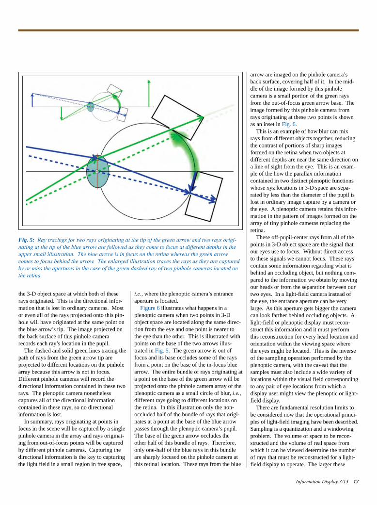
Figure 5 traces four rays as they traversethe pupil and are projected onto the pinholecamera array. One ray from each of the blueand green arrow tips passes through the centerof the pupil; these rays are shown as dashedlines in the figure. A second ray from eacharrow’s tip passes through the same peripherallocation in the pupil; these rays are repre-sented as solid lines.
The blue arrow is in focus, so the lens proj-ects both the dashed and solid blue rays to thesame pinhole camera location in the tiny cam-era array. The two rays are traced as they passthrough the pinhole at this location and areprojected onto the back surface of this tinycamera. The locations of the rays on the pin-hole camera’s back surface are correlated withthe entrance pupil locations of the rays, whichare correlated with the location of the point in
frontline technology
16 Information Display 3/13
Fig. 4: This diagram shows a schematic eyefocused on the blue arrow. The transparentblue and green bundles are the rays from theend points of both arrows that form images ofthe end points on the retina. The blue arrow’simage is sharp on the retina and the bundlesconverge to a point on the retina. The greenarrow would come to focus on a projectionplane behind the retina. Rays emanating fromthe green arrow end points are spread orblurred over a wide area of the retina. Whenan out-of-focus object occludes an in-focusobject, the blur reduces the image contrast ofparts of the in-focus object.
bThe tiny camera array does not necessarily have to bemade of pinhole cameras; these tiny cameras could havelenses. The principles of operation of the plenoptic camerawould be the same in either case.
Larimer p14-20_Layout 1 4/20/2013 9:48 PM Page 16
the 3-D object space at which both of theserays originated. This is the directional infor-mation that is lost in ordinary cameras. Mostor even all of the rays projected onto this pin-hole will have originated at the same point onthe blue arrow’s tip. The image projected onthe back surface of this pinhole camerarecords each ray’s location in the pupil.
The dashed and solid green lines tracing thepath of rays from the green arrow tip are projected to different locations on the pinholearray because this arrow is not in focus. Different pinhole cameras will record thedirectional information contained in these tworays. The plenoptic camera nonetheless captures all of the directional information contained in these rays, so no directionalinformation is lost.
In summary, rays originating at points infocus in the scene will be captured by a singlepinhole camera in the array and rays originat-ing from out-of-focus points will be capturedby different pinhole cameras. Capturing thedirectional information is the key to capturingthe light field in a small region in free space,
i.e., where the plenoptic camera’s entranceaperture is located.
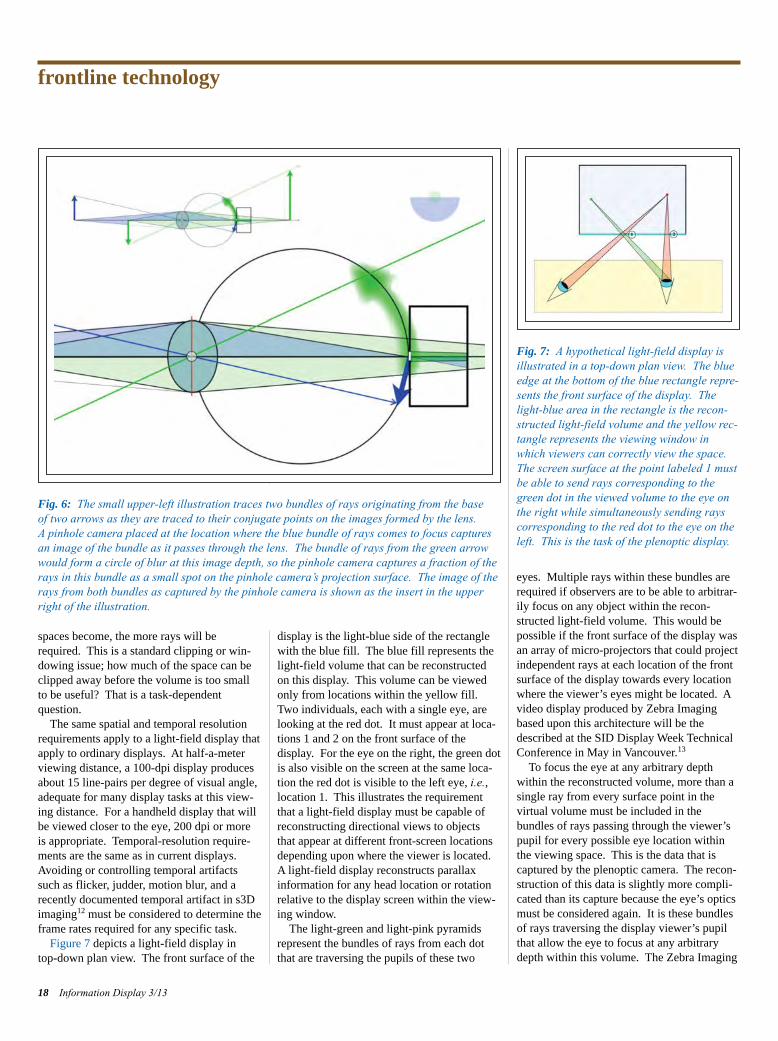
Figure 6 illustrates what happens in aplenoptic camera when two points in 3-Dobject space are located along the same direc-tion from the eye and one point is nearer tothe eye than the other. This is illustrated withpoints on the base of the two arrows illus-trated in Fig. 5. The green arrow is out offocus and its base occludes some of the raysfrom a point on the base of the in-focus bluearrow. The entire bundle of rays originating ata point on the base of the green arrow will beprojected onto the pinhole camera array of theplenoptic camera as a small circle of blur, i.e.,different rays going to different locations onthe retina. In this illustration only the non-occluded half of the bundle of rays that origi-nates at a point at the base of the blue arrowpasses through the plenoptic camera’s pupil.The base of the green arrow occludes theother half of this bundle of rays. Therefore,only one-half of the blue rays in this bundleare sharply focused on the pinhole camera atthis retinal location. These rays from the blue
arrow are imaged on the pinhole camera’sback surface, covering half of it. In the mid-dle of the image formed by this pinhole camera is a small portion of the green raysfrom the out-of-focus green arrow base. Theimage formed by this pinhole camera fromrays originating at these two points is shownas an inset in Fig. 6.
This is an example of how blur can mixrays from different objects together, reducingthe contrast of portions of sharp imagesformed on the retina when two objects at different depths are near the same direction ona line of sight from the eye. This is an exam-ple of the how the parallax information contained in two distinct plenoptic functionswhose xyz locations in 3-D space are sepa-rated by less than the diameter of the pupil islost in ordinary image capture by a camera orthe eye. A plenoptic camera retains this infor-mation in the pattern of images formed on thearray of tiny pinhole cameras replacing theretina.
These off-pupil-center rays from all of thepoints in 3-D object space are the signal thatour eyes use to focus. Without direct accessto these signals we cannot focus. These rayscontain some information regarding what isbehind an occluding object, but nothing com-pared to the information we obtain by movingour heads or from the separation between ourtwo eyes. In a light-field camera instead ofthe eye, the entrance aperture can be verylarge. As this aperture gets bigger the cameracan look farther behind occluding objects. Alight-field or plenoptic display must recon-struct this information and it must performthis reconstruction for every head location andorientation within the viewing space wherethe eyes might be located. This is the inverseof the sampling operation performed by theplenoptic camera, with the caveat that thesamples must also include a wide variety oflocations within the visual field correspondingto any pair of eye locations from which a display user might view the plenoptic or light-field display.
There are fundamental resolution limits tobe considered now that the operational princi-ples of light-field imaging have been described.Sampling is a quantization and a windowingproblem. The volume of space to be recon-structed and the volume of real space fromwhich it can be viewed determine the numberof rays that must be reconstructed for a light-field display to operate. The larger these
Information Display 3/13 17
Fig. 5: Ray tracings for two rays originating at the tip of the green arrow and two rays origi-nating at the tip of the blue arrow are followed as they come to focus at different depths in theupper small illustration. The blue arrow is in focus on the retina whereas the green arrowcomes to focus behind the arrow. The enlarged illustration traces the rays as they are capturedby or miss the apertures in the case of the green dashed ray of two pinhole cameras located onthe retina.
Larimer p14-20_Layout 1 4/20/2013 9:48 PM Page 17
spaces become, the more rays will berequired. This is a standard clipping or win-dowing issue; how much of the space can beclipped away before the volume is too smallto be useful? That is a task-dependent question.
The same spatial and temporal resolutionrequirements apply to a light-field display thatapply to ordinary displays. At half-a-meterviewing distance, a 100-dpi display producesabout 15 line-pairs per degree of visual angle,adequate for many display tasks at this view-ing distance. For a handheld display that willbe viewed closer to the eye, 200 dpi or moreis appropriate. Temporal-resolution require-ments are the same as in current displays.Avoiding or controlling temporal artifactssuch as flicker, judder, motion blur, and arecently documented temporal artifact in s3Dimaging12 must be considered to determine theframe rates required for any specific task.
Figure 7 depicts a light-field display in top-down plan view. The front surface of the
display is the light-blue side of the rectanglewith the blue fill. The blue fill represents thelight-field volume that can be reconstructedon this display. This volume can be viewedonly from locations within the yellow fill.Two individuals, each with a single eye, arelooking at the red dot. It must appear at loca-tions 1 and 2 on the front surface of the display. For the eye on the right, the green dotis also visible on the screen at the same loca-tion the red dot is visible to the left eye, i.e.,location 1. This illustrates the requirementthat a light-field display must be capable ofreconstructing directional views to objectsthat appear at different front-screen locationsdepending upon where the viewer is located.A light-field display reconstructs parallaxinformation for any head location or rotationrelative to the display screen within the view-ing window.
The light-green and light-pink pyramidsrepresent the bundles of rays from each dotthat are traversing the pupils of these two
eyes. Multiple rays within these bundles arerequired if observers are to be able to arbitrar-ily focus on any object within the recon-structed light-field volume. This would bepossible if the front surface of the display wasan array of micro-projectors that could projectindependent rays at each location of the frontsurface of the display towards every locationwhere the viewer’s eyes might be located. Avideo display produced by Zebra Imagingbased upon this architecture will be thedescribed at the SID Display Week TechnicalConference in May in Vancouver.13
To focus the eye at any arbitrary depthwithin the reconstructed volume, more than asingle ray from every surface point in the virtual volume must be included in the bundles of rays passing through the viewer’spupil for every possible eye location withinthe viewing space. This is the data that is captured by the plenoptic camera. The recon-struction of this data is slightly more compli-cated than its capture because the eye’s opticsmust be considered again. It is these bundlesof rays traversing the display viewer’s pupilthat allow the eye to focus at any arbitrarydepth within this volume. The Zebra Imaging
frontline technology
18 Information Display 3/13
Fig. 6: The small upper-left illustration traces two bundles of rays originating from the base of two arrows as they are traced to their conjugate points on the images formed by the lens. A pinhole camera placed at the location where the blue bundle of rays comes to focus capturesan image of the bundle as it passes through the lens. The bundle of rays from the green arrowwould form a circle of blur at this image depth, so the pinhole camera captures a fraction of therays in this bundle as a small spot on the pinhole camera’s projection surface. The image of therays from both bundles as captured by the pinhole camera is shown as the insert in the upperright of the illustration.
Fig. 7: A hypothetical light-field display isillustrated in a top-down plan view. The blueedge at the bottom of the blue rectangle repre-sents the front surface of the display. Thelight-blue area in the rectangle is the recon-structed light-field volume and the yellow rec-tangle represents the viewing window inwhich viewers can correctly view the space.The screen surface at the point labeled 1 mustbe able to send rays corresponding to thegreen dot in the viewed volume to the eye onthe right while simultaneously sending rayscorresponding to the red dot to the eye on theleft. This is the task of the plenoptic display.
Larimer p14-20_Layout 1 4/20/2013 9:48 PM Page 18
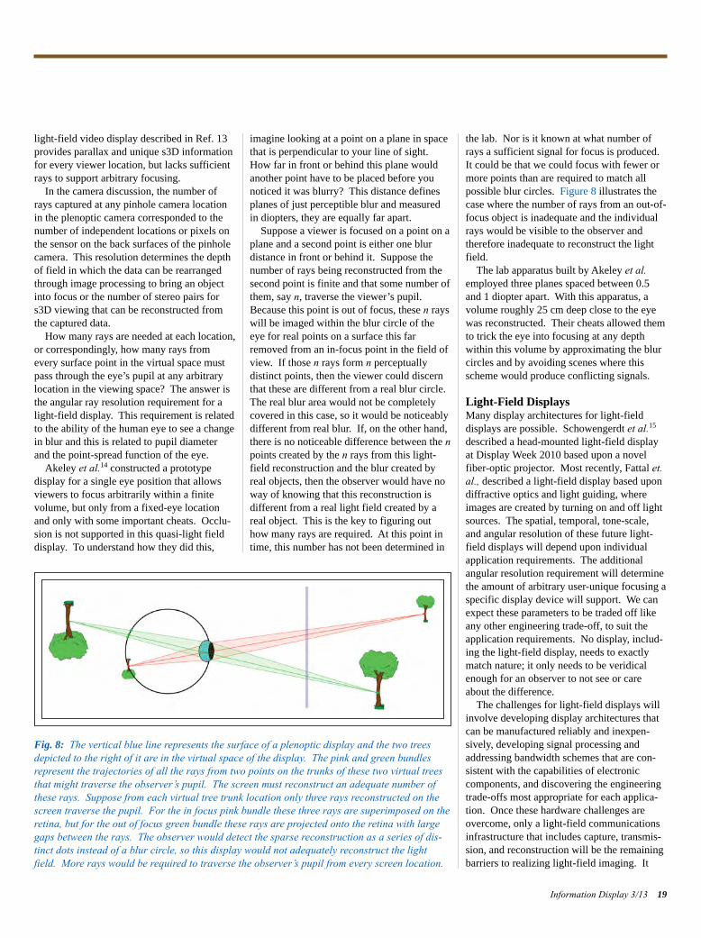
light-field video display described in Ref. 13provides parallax and unique s3D informationfor every viewer location, but lacks sufficientrays to support arbitrary focusing.
In the camera discussion, the number ofrays captured at any pinhole camera locationin the plenoptic camera corresponded to thenumber of independent locations or pixels onthe sensor on the back surfaces of the pinholecamera. This resolution determines the depthof field in which the data can be rearrangedthrough image processing to bring an objectinto focus or the number of stereo pairs fors3D viewing that can be reconstructed fromthe captured data.
How many rays are needed at each location,or correspondingly, how many rays fromevery surface point in the virtual space mustpass through the eye’s pupil at any arbitrarylocation in the viewing space? The answer isthe angular ray resolution requirement for alight-field display. This requirement is relatedto the ability of the human eye to see a changein blur and this is related to pupil diameterand the point-spread function of the eye.
Akeley et al.14 constructed a prototype display for a single eye position that allowsviewers to focus arbitrarily within a finite volume, but only from a fixed-eye locationand only with some important cheats. Occlu-sion is not supported in this quasi-light fielddisplay. To understand how they did this,
imagine looking at a point on a plane in spacethat is perpendicular to your line of sight.How far in front or behind this plane wouldanother point have to be placed before younoticed it was blurry? This distance definesplanes of just perceptible blur and measuredin diopters, they are equally far apart.
Suppose a viewer is focused on a point on aplane and a second point is either one blur distance in front or behind it. Suppose thenumber of rays being reconstructed from thesecond point is finite and that some number ofthem, say n, traverse the viewer’s pupil.Because this point is out of focus, these n rayswill be imaged within the blur circle of theeye for real points on a surface this farremoved from an in-focus point in the field ofview. If those n rays form n perceptually distinct points, then the viewer could discernthat these are different from a real blur circle.The real blur area would not be completelycovered in this case, so it would be noticeablydifferent from real blur. If, on the other hand,there is no noticeable difference between the npoints created by the n rays from this light-field reconstruction and the blur created byreal objects, then the observer would have noway of knowing that this reconstruction is different from a real light field created by areal object. This is the key to figuring outhow many rays are required. At this point intime, this number has not been determined in
the lab. Nor is it known at what number ofrays a sufficient signal for focus is produced.It could be that we could focus with fewer ormore points than are required to match allpossible blur circles. Figure 8 illustrates thecase where the number of rays from an out-of-focus object is inadequate and the individualrays would be visible to the observer andtherefore inadequate to reconstruct the lightfield.
The lab apparatus built by Akeley et al.employed three planes spaced between 0.5and 1 diopter apart. With this apparatus, avolume roughly 25 cm deep close to the eyewas reconstructed. Their cheats allowed themto trick the eye into focusing at any depthwithin this volume by approximating the blurcircles and by avoiding scenes where thisscheme would produce conflicting signals.
Light-Field DisplaysMany display architectures for light-field displays are possible. Schowengerdt et al.15
described a head-mounted light-field displayat Display Week 2010 based upon a novelfiber-optic projector. Most recently, Fattal et.al., described a light-field display based upondiffractive optics and light guiding, whereimages are created by turning on and off lightsources. The spatial, temporal, tone-scale,and angular resolution of these future light-field displays will depend upon individualapplication requirements. The additionalangular resolution requirement will determinethe amount of arbitrary user-unique focusing aspecific display device will support. We canexpect these parameters to be traded off likeany other engineering trade-off, to suit theapplication requirements. No display, includ-ing the light-field display, needs to exactlymatch nature; it only needs to be veridicalenough for an observer to not see or careabout the difference.
The challenges for light-field displays willinvolve developing display architectures thatcan be manufactured reliably and inexpen-sively, developing signal processing andaddressing bandwidth schemes that are con-sistent with the capabilities of electronic components, and discovering the engineeringtrade-offs most appropriate for each applica-tion. Once these hardware challenges areovercome, only a light-field communicationsinfrastructure that includes capture, transmis-sion, and reconstruction will be the remainingbarriers to realizing light-field imaging. It
Information Display 3/13 19
Fig. 8: The vertical blue line represents the surface of a plenoptic display and the two treesdepicted to the right of it are in the virtual space of the display. The pink and green bundlesrepresent the trajectories of all the rays from two points on the trunks of these two virtual treesthat might traverse the observer’s pupil. The screen must reconstruct an adequate number ofthese rays. Suppose from each virtual tree trunk location only three rays reconstructed on thescreen traverse the pupil. For the in focus pink bundle these three rays are superimposed on theretina, but for the out of focus green bundle these rays are projected onto the retina with largegaps between the rays. The observer would detect the sparse reconstruction as a series of dis-tinct dots instead of a blur circle, so this display would not adequately reconstruct the lightfield. More rays would be required to traverse the observer’s pupil from every screen location.
Larimer p14-20_Layout 1 4/20/2013 9:48 PM Page 19
was only 20 years ago that some people doubted that the CRT could ever be completelyreplaced as the backbone of video technology;it would be difficult to speculate on how rapidly light-field technology will roll out.
References1J. Needham, Science and Civilization inChina: Volume 4, Physics and Physical Tech-nology, Part 1, Physics (Caves Books, Ltd.,Taipei, 1986); Aristotle, Problems, Book XV;J. P. Richter, ed., The Notebooks of Leonardoda Vinci (Dover, New York, 1970).2M. F. Land and D-E. Nilsson, Animal Eyes(Oxford University Press, ISBN 0-19-850968-5, 2001).3M. Faraday, “Thoughts on Ray Vibrations,”Philosophical Magazine, S.3, Vol. XXVIII,N188 (May 1846).4A. Gershun, “The Light Field” (Moscow,1936). Translated by P. Moon and G. Timo-shenko in Journal of Mathematics andPhysics, Vol. XVIII, pp. 51–151 (MIT Press,Cambridge, MA, 1939).
5E. H. Adelson and J. R. Bergen, “The plenop-tic function and the elements of early vision,”in Computation Models of Visual Processing,M. Landy and J. A. Movshon, eds. (MITPress, Cambridge, MA, 1991), pp. 3–20.6J. J. Gibson, The Senses Considered as Perceptual Systems (Houghton Mifflin,Boston, MA, 1955), ISBN 0-313-23961-4; J. J. Gibson, “The Theory of Affordances,” in R. Shaw & J. Bransford, eds., Perceiving,Acting, and Knowing: Toward an EcologicalPsychology (Lawrence Erlbaum, Hillsdale,NJ, 1977), pp. 67–82.7R. T. Held, E. A. Cooper, and M. S. Banks,“Blur and Disparity Are Complementary Cuesto Depth,” Current Biology 22, 1–6 (2012); R. T. Held, E. A. Cooper, J. F. O’Brien, andM. S. Banks, “Using Blur to Affect PerceivedDistance and Size,” ACM Transactions onGraphics 29, 1–16 (2010).8G. Lippmann, “Epreuves reversible donnantla sensation du relief,” J. de Physique 7, 821–825 (1908); H. E., Ives, “Parallax Panorama-grams Made Possible with a Large Diameter
Lens,” JOSA 20, 332–342 (1930).9T. Adelson and J. Y. A. Wang, “Single lensstereo with a plenoptic camera,” IEEE Trans-actions on Pattern Analysis and MachineIntelligence 14, 2 (Feb), 99–106 (1992).10R. Ng, M. Levoy, M. Brédif, G. Duval, M. Horowitz, and P. Hanrahan, Light Field Photography with a Hand-held PlenopticCamera, Stanford Tech Report CTSR 2005-02.11www.lytro.com and www.raytrix.de12D. M. Hoffman, V. I. Karasev, and M. S.Banks, “Temporal Presentation Protocols inStereoscopic Displays: Flicker Visibility, Perceived Motion, and Perceived Depth, J. Soc. Info. Display 19, 255–281 (2011).13M. Klug, T. Burnett, A. Fancello, A. Heath, K. Gardner, S. O’Connell, and C. A. Newswanger, “Scalable, Collaborative,Interactive Light-Field Display System” (to be published in the 2013 SID SymposiumDigest of Technical Papers).14K. Akeley, S. J. Watt, A. R. Girshick, and M. S. Banks, “A Stereo Display Prototypewith Multiple Focal Distances,” ACM Trans-actions on Graphics 23, I804–813 (2004).; K. Akeley, “Achieving Near-Correct FocusCues Using Multiple Image Planes, Disserta-tion submitted to the Department of ElectricalEngineering and the Committee on GraduateStudies of Stanford University (2004).15B. T. Schowengerdt, M. Murari, and E. J. Seibel, “Volumetric Display UsingScanned Fiber Array,” SID Symposium Digest Tech. Paper 41, 653-656 (2010).16D. Fattal, Z. Peng, T. Tran, S. Vo, M. Fiorentino, J. Brug, and R. G. Beausoleil, “A Multi-Directional Backlight for a Wide-Angle, Glasses-Free Three-Dimensional Display,” Nature 495, 348–351 (2013). n
frontline technology
20 Information Display 3/13
Display Week 2014SID International Symposium,
Seminar & ExhibitionJune 1–6, 2014
San Diego Convention CenterSan Diego, California, USA
www.displayweek.org
JOIN SIDWe invite you to join SID to participate in shapingthe future development of:
• Display technologies and display-related products
• Materials and components for displays and displayapplications
• Manufacturing processes and equipment• New markets and applications
In every specialty you will find SID members as leading contributors to their profession.
http://www.sid.org/Membership.aspx
Larimer p14-20_Layout 1 4/20/2013 9:48 PM Page 20
daw
ar.c
om
1016 NORTH LINCOLN AVE PITTSBURGH, PA 15233 PH: 1.800.366.1904 / 412.322.9900 E: [email protected]
Multi-Touch Projected Capacitive Touch Screens
Sensor manufacturing in the USA at Dawar’s Pittsburgh facility
Full U.S. based engineering support
Rugged Design - All glass construction that provides ≥ 9H pencil hardness and superior optics
Enhanced Sensitivity - Light touch for effortless input with finger, glove or conductive stylus
Gesture Capability - pinch, flick, tap, click and rotate
Standard Product - Controller Board solutions from 4.3"W - 24"W - Chip on Flex solutions from 4.3"W - 17"
Customization - Decorative front lens available for tablet PC look
System tuning at Dawar's Pittsburgh facility
A M E R I C A N M A D E
Come visit us at Display Week 2013, BOOTH 309
Multi-
ojectouch PrTMulti-
e Ted Capacitivoject
eensouch Scre T Touch Scr
eens
m
o.cr
a
aw
d
.S. based engineering supportFull U
acturing in the USSensor manuf
.S. based engineering support
s Pittsbur’arwt DaA aacturing in the US
acilitygh fs Pittsbur
tivaortion - DecomizatCus
- Chip on Fleoller Boarontroduct - Cd PrtandarS
e Capability - pinch, flick, tapturGes
tyluse sonductive or cvgloed Sensitivity - Light tEnhanc
s and superior opticsdneshars cRugged Design - All glas
.S. based engineering supportFull U
or tablet PC lookailable fvont lens ae fr
om 4.3"W - 17"x solutions fr- Chip on Fleom 4.3"W - 2d solutions froller Boar
etota, click and re Capability - pinch, flick, tap
s input with fingerortlesor effouch fed Sensitivity - Light t
s and superior opticsvides ot prtruction thaonss c
.S. based engineering support
or tablet PC look
om 4.3"W - 17"4"W om 4.3"W - 2
, s input with finger
9H pencil ≥vides
TH LINC16 NOR10
A 15SBURGH, PVE PITTOLN ATH LINC
1904 / 4
ar's Pittsbur
.366.PH: 1.800233 A 15
wt Daem tuning atsyS
ALES@D
acility
12.322.9900 E: S1904 / 4
gh far's Pittsbur
OMCAR.WAALES@D
Dawar Ad p21_Layout 1 4/20/2013 9:52 PM Page 21
THE development of technology hasgreatly transformed the media used for all ourcommunications, providing waves of newelectronic information that amuse, inform,entertain, and often aggravate. Some of thesemedia technologies, though they may initiallyseem solely frivolous, ultimately become sointegrated that they become indistinguishablefrom the environment itself. A perfect exam-ple is the personal computer, initially seen as atoy of no practical use. Its key component,the micro-processor (or the modern daymicro-controller), is now in myriad formspractically invisible in our watches, books,home appliances, cars, cash registers, tele-phones, address books, and flower pots. The recent advances in light-fielda displays,
and in light-field capture in particular (Fig. 1),put a new twist into the process of integrationbecause the idealized light-field display in asense actually disappears, leaving only thelight field emitted from a volume of space.1–4Viewers of an idealized display are thus leftwith a window into a world seen as a volumewith all its physical features. When fullydeveloped, this view could be indistinguish-able from what they would see if they werelooking through a physical window. What
would such a capture and display system begood for?By analogy with previously developed
technology we can be sure such displays willalso amuse, inform, entertain, and aggravateus. But it seems to me hubris to claim toknow what the first “killer app” for such displays will be. They may have scientificapplications. They may have medical applica-tions. They seem to be natural visual formatsfor home and theater entertainment, a kind ofultimate autostereoscopic display. Indeed,since they do not have specific eye points forimage rendering, they are really beyondstereoscopic display. But to assert with anyreasonable degree of confidence how, where,or why light-field technology will change theworld seems premature, especially since thereare not many established systems that includeboth capture and light-field display, and theconstraints on their use are not well known.(Figure 1 illustrates two currently availableproducts that are designed to capture light-field data.) However, whatever applicationsultimately succeed, they will succeed becausethey communicate information to their users.
Communication through the AmbientOptic ArrayThe physical essence of the light field is theplenoptic function, which is discussed in thisissue’s article, “The Road Ahead to the
Holodeck: Light-Field Imaging and Display,”by James Larimer. Interestingly, the plenopticfunction has a psychological/semantic aspectthat Gibson5 called the ambient optic array.This array may be thought of as the structuredlight, contour, shading, gradients, and shapesthat the human visual system detects in thatpart of the light field that enters the eye. Thefeatures of the ambient optic array are prima-rily semantic rather than physical and relate tothe array of behavior possibilities the lightfield opens to the viewer. These features are in a sense the natural
semantics of our environment to which wehave become sensitive through the processesof evolution. The array was consideredimportant by Gibson because it presents theviewer with information about the environ-ment that is invariant with respect to manyspecific viewing parameters, e.g., direction ofview, motion, and egocentric position. Thearray thus allows viewers to determine envi-ronmental properties such as distance, slope,roughness, manual reachability of objects, orthe accessibility of openings such as doors.
Communication through the Light Field: An EssayIn the foregoing article, “The Road Ahead to the Holodeck: Light-Field Imaging and Display,”James Larimer discusses the evolution of vision and the nature of light-field displays. This article looks at the physical, economic, and social factors that influence the success of information technology applications in terms that could apply to light-field systems.
by Stephen R. Ellis
Stephen R. Ellis is with the NASA Ames Research Center. He can be reached at [email protected].
22 Information Display 3/130362-0972/3/2013-022$1.00 + .00 © SID 2013
frontline technology
aThe light field, considered primarily in terms of the lightrays of geometrical optics, is defined as radiance as a function of all possible positions and directions in regionsof a space free of occluders. Since rays in space can beparameterized by three spatial coordinates, x, y, and z ,andtwo angles, the light field, therefore, is a five-dimensionalfunction. (See the article by Larimer in this issue.)
Ellis p22-26_Layout 1 4/20/2013 9:58 PM Page 22
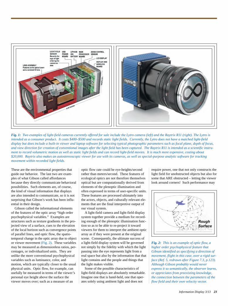
These are the environmental properties thatguide our behavior. The last two are exam-ples of what Gibson called affordancesbecause they directly communicate behavioralpossibilities. Such elements are, of course,the kind of visual information that displaysare also intended to communicate, so it is notsurprising that Gibson’s work has been influ-ential in their design.Gibson called the informational elements
of the features of the optic array “high order psychophysical variables.” Examples arestructures such as texture gradients in the pro-jected view of a surface, cues to the elevation of the local horizon such as convergence points of parallel lines, and optic flow, the spatio-temporal change in the optic array due to object or viewer movement (Fig. 2). These variablesmay be measured as dimensionless ratios, per-centages, or individualized units. They areunlike the more conventional psychophysicalvariables such as luminance, color, andmotion, which are typically closer to the usualphysical units. Optic flow, for example, canusefully be measured in terms of the viewer’spersonal eye height above the surface theviewer moves over; such as a measure of an
optic flow rate could be eye-heights/secondrather than meters/second. These features ofecological optics are not therefore themselvesoptical but are computationally derived fromelements of the plenoptic illumination andoften expressed in terms of user-specific units.These features are processed ultimately intothe actors, objects, and culturally relevant ele-ments that are the final interpretive output ofour visual system.A light-field camera and light-field display
system together provide a medium for record-ing enough of the plenoptic illumination func-tion so as to be able to re-project it towardviewers for them to interpret the ambient opticarray as if they were present at the originalscene. Consequently, the ultimate success ofa light-field display system will be governednot simply by the fidelity with which the lightpassing into the eye represents light from areal space but also by the information that thatlight contains and the people and things thatthe light makes visible.Some of the possible characteristics of
light-field displays are absolutely remarkable.Imagine one that is hand-held, one that oper-ates solely using ambient light and does not
require power, one that not only constructs thelight field for unobstructed objects but also forsome that ARE obstructed – letting the viewerlook around corners! Such performance may
Information Display 3/13 23
Fig. 1: Two examples of light-field cameras currently offered for sale include the Lytro camera (left) and the Raytrix R11 (right). The Lytro isintended as a consumer product. It costs $400–$500 and records static light fields. Currently, the Lytro does not have a matched light-field display but does include a built-in viewer and laptop software for selecting typical photographic parameters such as focal plane, depth of focus,and view direction for creation of conventional images after the light field has been captured. The Raytrix R11 is intended as a scientific instru-ment to record volumetric motion as well as static light fields and can record light-field movies. It is much more expensive, costing about$20,000. Raytrix also makes an autostereoscopic viewer for use with its cameras, as well as special-purpose analytic software for tracking movement within recorded light fields.
Fig. 2: This is an example of optic flow, ahigher order psychophysical feature that Gibson identified as specifying a direction ofmovement, flight in this case, over a rigid sur-face (Ref. 5, redrawn after Figure 7.3, p.123).Although Gibson probably would neverexpress it so semantically, the observer learns,or appreciates from preexisting knowledge,the connection between the parameters of theflow field and their own velocity vector.
Ellis p22-26_Layout 1 4/20/2013 9:58 PM Page 23
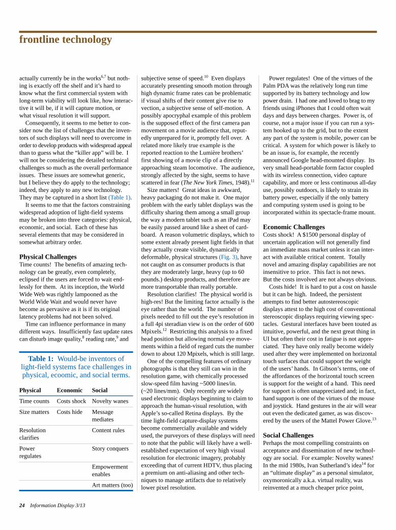
actually currently be in the works6,7 but noth-ing is exactly off the shelf and it’s hard toknow what the first commercial system withlong-term viability will look like, how interac-tive it will be, if it will capture motion, orwhat visual resolution it will support. Consequently, it seems to me better to con-
sider now the list of challenges that the inven-tors of such displays will need to overcome inorder to develop products with widespread appeal than to guess what the “killer app” will be. Iwill not be considering the detailed technical challenges so much as the overall performance issues. These issues are somewhat generic,but I believe they do apply to the technology;indeed, they apply to any new technology.They may be captured in a short list (Table 1). It seems to me that the factors constraining
widespread adoption of light-field systemsmay be broken into three categories: physical,economic, and social. Each of these has several elements that may be considered insomewhat arbitrary order.
Physical ChallengesTime counts! The benefits of amazing tech-nology can be greatly, even completely,eclipsed if the users are forced to wait end-lessly for them. At its inception, the WorldWide Web was rightly lampooned as theWorld Wide Wait and would never havebecome as pervasive as it is if its originallatency problems had not been solved. Time can influence performance in many
different ways. Insufficiently fast update ratescan disturb image quality,8 reading rate,9 and
subjective sense of speed.10 Even displaysaccurately presenting smooth motion throughhigh dynamic frame rates can be problematicif visual shifts of their content give rise tovection, a subjective sense of self-motion. Apossibly apocryphal example of this problemis the supposed effect of the first camera panmovement on a movie audience that, reput-edly unprepared for it, promptly fell over. Arelated more likely true example is thereported reaction to the Lumière brothers’ first showing of a movie clip of a directlyapproaching steam locomotive. The audience,strongly affected by the sight, seems to have scattered in fear (The New York Times, 1948).11Size matters! Great ideas in awkward,
heavy packaging do not make it. One majorproblem with the early tablet displays was thedifficulty sharing them among a small groupthe way a modern tablet such as an iPad maybe easily passed around like a sheet of card-board. A reason volumetric displays, which tosome extent already present light fields in thatthey actually create visible, dynamicallydeformable, physical structures (Fig. 3), havenot caught on as consumer products is thatthey are moderately large, heavy (up to 60pounds.) desktop products, and therefore aremore transportable than really portable.Resolution clarifies! The physical world is
high-res! But the limiting factor actually is theeye rather than the world. The number of pixels needed to fill out the eye’s resolution ina full 4pi steradian view is on the order of 600Mpixels.12 Restricting this analysis to a fixedhead position but allowing normal eye move-ments within a field of regard cuts the number down to about 120 Mpixels, which is still large.One of the compelling features of ordinary
photographs is that they still can win in theresolution game, with chemically processedslow-speed film having ~5000 lines/in. (~20 lines/mm). Only recently are widelyused electronic displays beginning to claim toapproach the human-visual resolution, withApple’s so-called Retina displays. By thetime light-field capture-display systemsbecome commercially available and widelyused, the purveyors of these displays will needto note that the public will likely have a well-established expectation of very high visualresolution for electronic imagery, probablyexceeding that of current HDTV, thus placinga premium on anti-aliasing and other tech-niques to manage artifacts due to relativelylower pixel resolution.
Power regulates! One of the virtues of thePalm PDA was the relatively long run timesupported by its battery technology and low power drain. I had one and loved to brag to my friends using iPhones that I could often waitdays and days between charges. Power is, ofcourse, not a major issue if you can run a sys-tem hooked up to the grid, but to the extentany part of the system is mobile, power can becritical. A system for which power is likely tobe an issue is, for example, the recentlyannounced Google head-mounted display. Itsvery small head-portable form factor coupledwith its wireless connection, video capturecapability, and more or less continuous all-dayuse, possibly outdoors, is likely to strain itsbattery power, especially if the only batteryand computing system used is going to be incorporated within its spectacle-frame mount.
Economic ChallengesCosts shock! A $1500 personal display ofuncertain application will not generally findan immediate mass market unless it can inter-act with available critical content. Totallynovel and amazing display capabilities are notinsensitive to price. This fact is not news.But the costs involved are not always obvious.Costs hide! It is hard to put a cost on hassle
but it can be high. Indeed, the persistentattempts to find better autostereoscopic displays attest to the high cost of conventionalstereoscopic displays requiring viewing spec-tacles. Gestural interfaces have been touted asintuitive, powerful, and the next great thing inUI but often their cost in fatigue is not appre-ciated. They have only really become widelyused after they were implemented on horizontaltouch surfaces that could support the weightof the users’ hands. In Gibson’s terms, one ofthe affordances of the horizontal touch screenis support for the weight of a hand. This needfor support is often unappreciated and; in fact, hand support is one of the virtues of the mouse and joystick. Hand gestures in the air will wear out even the dedicated gamer, as was discov-ered by the users of the Mattel Power Glove.13
Social ChallengesPerhaps the most compelling constraints onacceptance and dissemination of new technol-ogy are social. For example: Novelty wanes!In the mid 1980s, Ivan Sutherland’s idea14 foran “ultimate display” as a personal simulator,oxymoronically a.k.a. virtual reality, was reinvented at a much cheaper price point,
frontline technology
24 Information Display 3/13
Table 1: Would-be inventors oflight-field systems face challenges inphysical, ecoomic, and social terms.
Physical Economic Social
Time counts Costs shock Novelty wanes
Size matters Costs hide Message mediates
Resolution Content rulesclarifies
Power Story conquersregulates
Empowermentenables
Art matters (too)
Ellis p22-26_Layout 1 4/20/2013 9:58 PM Page 24
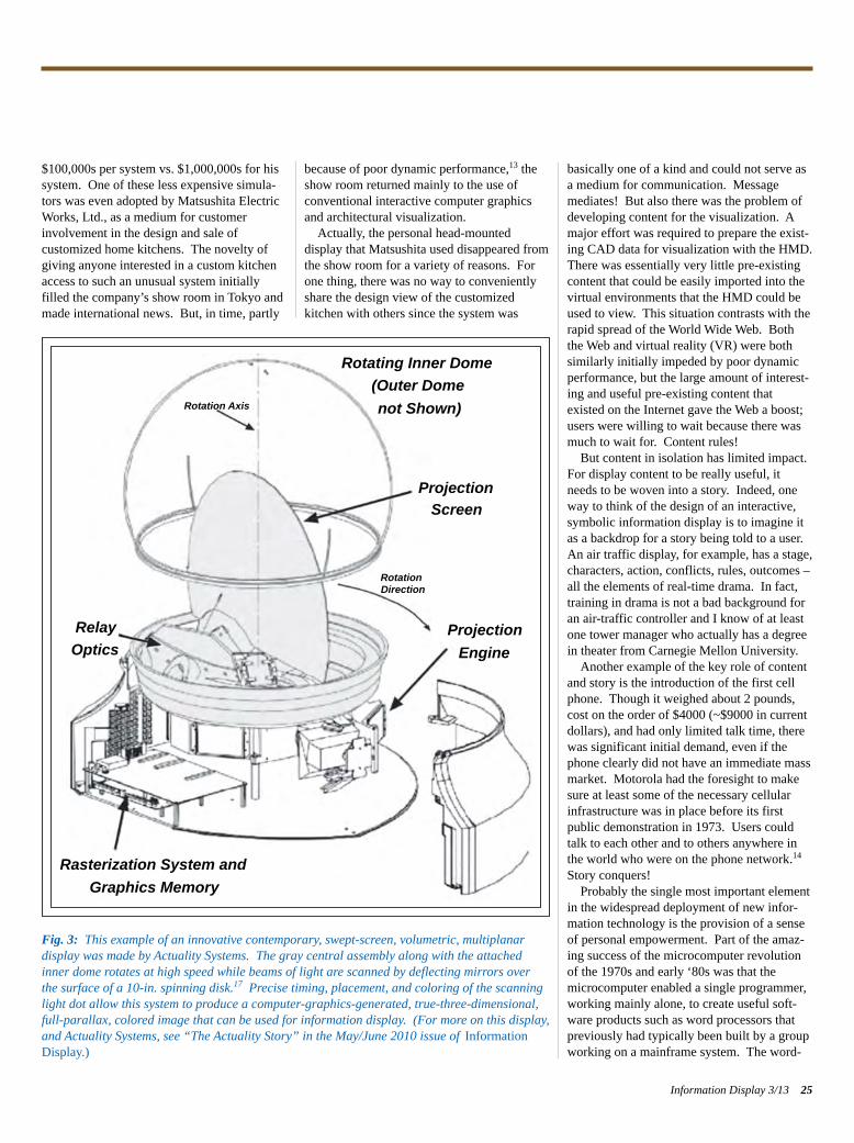
$100,000s per system vs. $1,000,000s for hissystem. One of these less expensive simula-tors was even adopted by Matsushita ElectricWorks, Ltd., as a medium for customerinvolvement in the design and sale of customized home kitchens. The novelty ofgiving anyone interested in a custom kitchenaccess to such an unusual system initiallyfilled the company’s show room in Tokyo andmade international news. But, in time, partly
because of poor dynamic performance,13 theshow room returned mainly to the use of conventional interactive computer graphicsand architectural visualization. Actually, the personal head-mounted
display that Matsushita used disappeared fromthe show room for a variety of reasons. Forone thing, there was no way to convenientlyshare the design view of the customizedkitchen with others since the system was
basically one of a kind and could not serve asa medium for communication. Messagemediates! But also there was the problem ofdeveloping content for the visualization. Amajor effort was required to prepare the exist-ing CAD data for visualization with the HMD.There was essentially very little pre-existingcontent that could be easily imported into thevirtual environments that the HMD could beused to view. This situation contrasts with therapid spread of the World Wide Web. Boththe Web and virtual reality (VR) were bothsimilarly initially impeded by poor dynamicperformance, but the large amount of interest-ing and useful pre-existing content thatexisted on the Internet gave the Web a boost;users were willing to wait because there wasmuch to wait for. Content rules!But content in isolation has limited impact.
For display content to be really useful, itneeds to be woven into a story. Indeed, oneway to think of the design of an interactive,symbolic information display is to imagine itas a backdrop for a story being told to a user.An air traffic display, for example, has a stage,characters, action, conflicts, rules, outcomes –all the elements of real-time drama. In fact,training in drama is not a bad background foran air-traffic controller and I know of at leastone tower manager who actually has a degreein theater from Carnegie Mellon University.Another example of the key role of content
and story is the introduction of the first cellphone. Though it weighed about 2 pounds,cost on the order of $4000 (~$9000 in currentdollars), and had only limited talk time, therewas significant initial demand, even if thephone clearly did not have an immediate massmarket. Motorola had the foresight to makesure at least some of the necessary cellularinfrastructure was in place before its first public demonstration in 1973. Users couldtalk to each other and to others anywhere inthe world who were on the phone network.14Story conquers!Probably the single most important element
in the widespread deployment of new infor-mation technology is the provision of a senseof personal empowerment. Part of the amaz-ing success of the microcomputer revolutionof the 1970s and early ‘80s was that themicrocomputer enabled a single programmer,working mainly alone, to create useful soft-ware products such as word processors thatpreviously had typically been built by a groupworking on a mainframe system. The word-
Information Display 3/13 25
Fig. 3: This example of an innovative contemporary, swept-screen, volumetric, multiplanar display was made by Actuality Systems. The gray central assembly along with the attachedinner dome rotates at high speed while beams of light are scanned by deflecting mirrors over the surface of a 10-in. spinning disk.17 Precise timing, placement, and coloring of the scanninglight dot allow this system to produce a computer-graphics-generated, true-three-dimensional,full-parallax, colored image that can be used for information display. (For more on this display,and Actuality Systems, see “The Actuality Story” in the May/June 2010 issue of InformationDisplay.)
Rotating Inner Dome(Outer Domenot Shown)
Projection
ProjectionEngine
RotationDirection
Rotation Axis
Relay
Rasterization System andGraphics Memory
Optics
Screen
Ellis p22-26_Layout 1 4/20/2013 9:58 PM Page 25
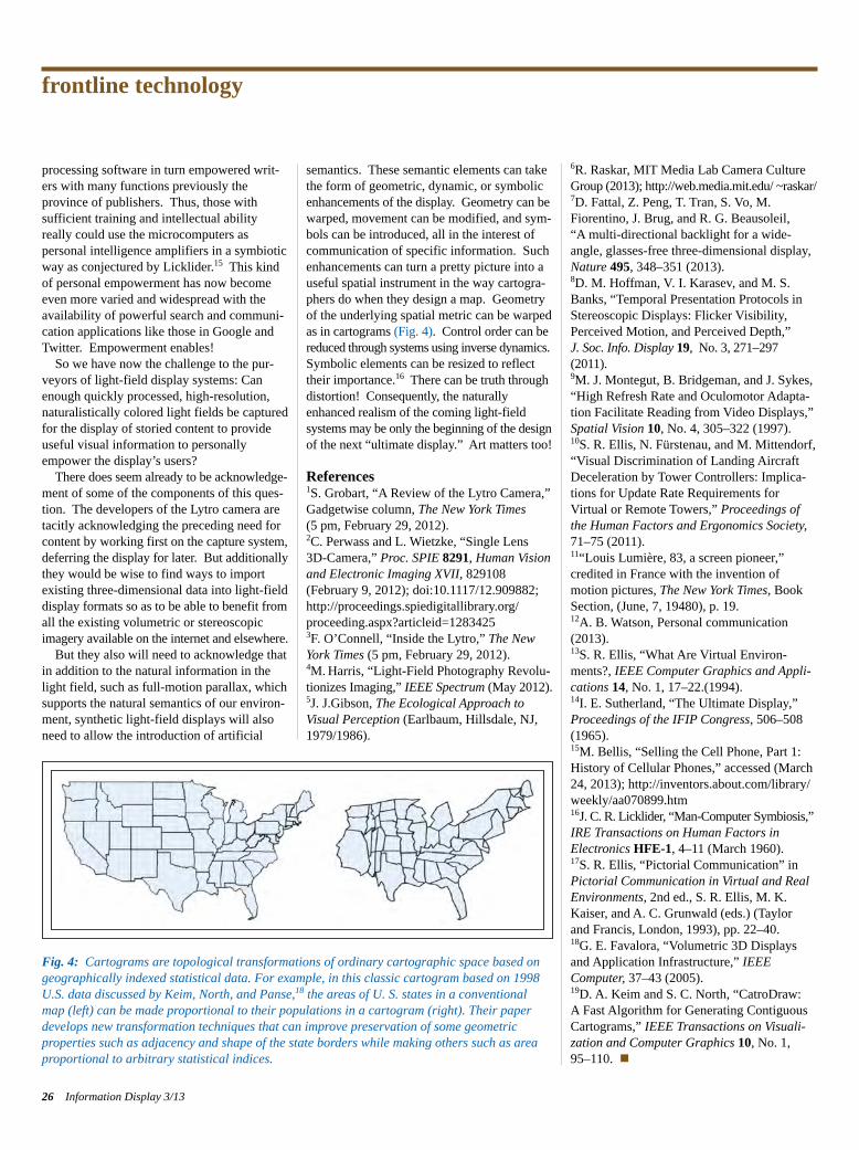
processing software in turn empowered writ-ers with many functions previously theprovince of publishers. Thus, those with sufficient training and intellectual abilityreally could use the microcomputers as personal intelligence amplifiers in a symbioticway as conjectured by Licklider.15 This kindof personal empowerment has now becomeeven more varied and widespread with theavailability of powerful search and communi-cation applications like those in Google andTwitter. Empowerment enables!So we have now the challenge to the pur-
veyors of light-field display systems: Canenough quickly processed, high-resolution,naturalistically colored light fields be capturedfor the display of storied content to provideuseful visual information to personallyempower the display’s users?There does seem already to be acknowledge-
ment of some of the components of this ques-tion. The developers of the Lytro camera aretacitly acknowledging the preceding need for content by working first on the capture system, deferring the display for later. But additionally they would be wise to find ways to import existing three-dimensional data into light-field display formats so as to be able to benefit from all the existing volumetric or stereoscopic imagery available on the internet and elsewhere.But they also will need to acknowledge that
in addition to the natural information in thelight field, such as full-motion parallax, whichsupports the natural semantics of our environ-ment, synthetic light-field displays will alsoneed to allow the introduction of artificial
semantics. These semantic elements can takethe form of geometric, dynamic, or symbolic enhancements of the display. Geometry can be warped, movement can be modified, and sym-bols can be introduced, all in the interest ofcommunication of specific information. Suchenhancements can turn a pretty picture into auseful spatial instrument in the way cartogra-phers do when they design a map. Geometryof the underlying spatial metric can be warped as in cartograms (Fig. 4). Control order can be reduced through systems using inverse dynamics. Symbolic elements can be resized to reflecttheir importance.16 There can be truth throughdistortion! Consequently, the naturallyenhanced realism of the coming light-field systems may be only the beginning of the design of the next “ultimate display.” Art matters too!
References1S. Grobart, “A Review of the Lytro Camera,”Gadgetwise column, The New York Times(5 pm, February 29, 2012).2C. Perwass and L. Wietzke, “Single Lens 3D-Camera,” Proc. SPIE 8291, Human Visionand Electronic Imaging XVII, 829108 (February 9, 2012); doi:10.1117/12.909882;http://proceedings.spiedigitallibrary.org/ proceeding.aspx?articleid=12834253F. O’Connell, “Inside the Lytro,” The NewYork Times (5 pm, February 29, 2012).4M.Harris, “Light-Field Photography Revolu-tionizes Imaging,” IEEE Spectrum (May 2012).5J. J.Gibson, The Ecological Approach toVisual Perception (Earlbaum, Hillsdale, NJ,1979/1986).
6R. Raskar, MIT Media Lab Camera CultureGroup (2013); http://web.media.mit.edu/ ~raskar/7D. Fattal, Z. Peng, T. Tran, S. Vo, M.Fiorentino, J. Brug, and R. G. Beausoleil, “A multi-directional backlight for a wide-angle, glasses-free three-dimensional display,Nature 495, 348–351 (2013).8D. M. Hoffman, V. I. Karasev, and M. S.Banks, “Temporal Presentation Protocols inStereoscopic Displays: Flicker Visibility, Perceived Motion, and Perceived Depth,” J. Soc. Info. Display 19, No. 3, 271–297(2011).9M. J. Montegut, B. Bridgeman, and J. Sykes,“High Refresh Rate and Oculomotor Adapta-tion Facilitate Reading from Video Displays,”Spatial Vision 10, No. 4, 305–322 (1997).10S. R. Ellis, N. Fürstenau, and M. Mittendorf,“Visual Discrimination of Landing AircraftDeceleration by Tower Controllers: Implica-tions for Update Rate Requirements for Virtual or Remote Towers,” Proceedings ofthe Human Factors and Ergonomics Society,71–75 (2011).11“Louis Lumière, 83, a screen pioneer,” credited in France with the invention ofmotion pictures, The New York Times, BookSection, (June, 7, 19480), p. 19.12A. B. Watson, Personal communication(2013).13S. R. Ellis, “What Are Vir tual Environ-ments?, IEEE Computer Graphics and Appli-cations 14, No. 1, 17–22.(1994).14I. E. Sutherland, “The Ultimate Display,”Proceedings of the IFIP Congress, 506–508(1965).15M. Bellis, “Selling the Cell Phone, Part 1:History of Cellular Phones,” accessed (March24, 2013); http://inventors.about.com/library/weekly/aa070899.htm16J. C. R. Licklider, “Man-Computer Symbiosis,”IRE Transactions on Human Factors in Electronics HFE-1, 4–11 (March 1960).17S. R. Ellis, “Pictorial Communication” inPictorial Communication in Virtual and RealEnvi ronments, 2nd ed., S. R. Ellis, M. K.Kaiser, and A. C. Grunwald (eds.) (Taylor and Francis, London, 1993), pp. 22–40.18G. E. Favalora, “Volumetric 3D Displaysand Application Infrastructure,” IEEE Computer, 37–43 (2005).19D. A. Keim and S. C. North, “CatroDraw: A Fast Algorithm for Generating ContiguousCartograms,” IEEE Transactions on Visuali-zation and Computer Graphics 10, No. 1, 95–110. n
frontline technology
26 Information Display 3/13
Fig. 4: Cartograms are topological transformations of ordinary cartographic space based ongeographically indexed statistical data. For example, in this classic cartogram based on 1998U.S. data discussed by Keim, North, and Panse,18 the areas of U. S. states in a conventionalmap (left) can be made proportional to their populations in a cartogram (right). Their paperdevelops new transformation techniques that can improve preservation of some geometric properties such as adjacency and shape of the state borders while making others such as areaproportional to arbitrary statistical indices.
Ellis p22-26_Layout 1 4/20/2013 9:58 PM Page 26
See PixClear™
Introducing PixClear™, zirconia nanocrystals for electronics and semiconductor applications. One of the highest-index nano-materials available, delivering perfectly clear dispersions in solvents, monomers and polymers for seamless integration into your products.
• High Refractive Index, >1.85• Highly Transparent at the Visible
Wavelengths• Low Haze Coatings Even at High
Nanocrystal Loading, >80 wt%• Improved Scratch Resistance and
Hardness• For Use in Touch Screens, CMOS Image
Sensors, LEDs and OLEDs
order online at:w w w . p i x e l l i g e n t . c o m / i d m a yO r c a l l 8 7 7 - 3 3 3 - 9 2 4 5 e x t . 1
new display designnew display design
Display Solutions· COG Displays· Touch Panels· Control Units· Intelligent Displays· RS-232 / I²C / SPI· USB Evaluationboard· German Engineering
since 1977
ELECTRONIC ASSEMBLY GmbH [email protected]
MOUSER ELECTRONICSwww.mouser.com
USB EvaluationboardGerman Engineering
new display designnew display designnew display designnew display designnew display designnew display designnew display designnew display designnew display designnew display designnew display designnew display design
Display Solutionsnew display designnew display designnew display designnew display designnew display designnew display designnew display designnew display designnew display designnew display designnew display designnew display designnew display designnew display designnew display designnew display designnew display designnew display designnew display designnew display designnew display designnew display designnew display designnew display designnew display designnew display designnew display designnew display designnew display designnew display designnew display designnew display designnew display designnew display designnew display designnew display designnew display designnew display designnew display designnew display designnew display designnew display designnew display designnew display designnew display designnew display designnew display designnew display designnew display designnew display designnew display designnew display designnew display designnew display designnew display designnew display designnew display designnew display designnew display designnew display designnew display designnew display designnew display designnew display designnew display designnew display designnew display designnew display designnew display design
Display Solutions
Distributed by Visit us:
German Pavilion
No. 1211
Visit us:
German Pavilion
See Us at Display Week 2013, Booth #1129
NDF ad SID DEF.indd 1 09-04-13 21:13Ad p27.indd 1 4/20/2013 10:11:27 PM
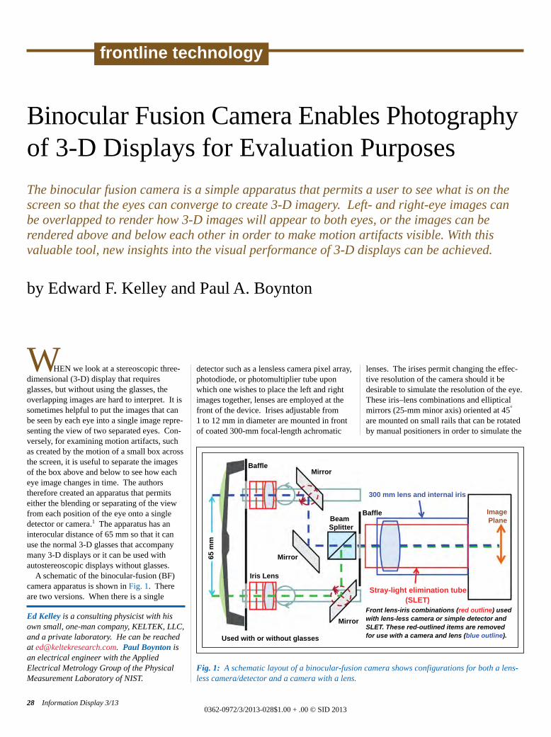
WHEN we look at a stereoscopic three-dimensional (3-D) display that requiresglasses, but without using the glasses, theoverlapping images are hard to interpret. It issometimes helpful to put the images that canbe seen by each eye into a single image repre-senting the view of two separated eyes. Con-versely, for examining motion artifacts, suchas created by the motion of a small box acrossthe screen, it is useful to separate the imagesof the box above and below to see how eacheye image changes in time. The authorstherefore created an apparatus that permitseither the blending or separating of the viewfrom each position of the eye onto a singledetector or camera.1 The apparatus has aninterocular distance of 65 mm so that it canuse the normal 3-D glasses that accompanymany 3-D displays or it can be used withautostereoscopic displays without glasses. A schematic of the binocular-fusion (BF)
camera apparatus is shown in Fig. 1. Thereare two versions. When there is a single
detector such as a lensless camera pixel array,photodiode, or photomultiplier tube uponwhich one wishes to place the left and rightimages together, lenses are employed at thefront of the device. Irises adjustable from1 to 12 mm in diameter are mounted in frontof coated 300-mm focal-length achromatic
lenses. The irises permit changing the effec-tive resolution of the camera should it bedesirable to simulate the resolution of the eye.These iris–lens combinations and ellipticalmirrors (25-mm minor axis) oriented at 45°are mounted on small rails that can be rotatedby manual positioners in order to simulate the
Binocular Fusion Camera Enables Photographyof 3-D Displays for Evaluation Purposes The binocular fusion camera is a simple apparatus that permits a user to see what is on the screen so that the eyes can converge to create 3-D imagery. Left- and right-eye images can be overlapped to render how 3-D images will appear to both eyes, or the images can be rendered above and below each other in order to make motion artifacts visible. With this valuable tool, new insights into the visual performance of 3-D displays can be achieved.
by Edward F. Kelley and Paul A. Boynton
Ed Kelley is a consulting physicist with hisown small, one-man company, KELTEK, LLC,and a private laboratory. He can be reachedat [email protected]. Paul Boynton isan electrical engineer with the Applied Electrical Metrology Group of the PhysicalMeasurement Laboratory of NIST.
28 Information Display 3/130362-0972/3/2013-028$1.00 + .00 © SID 2013
frontline technology
Fig. 1: A schematic layout of a binocular-fusion camera shows configurations for both a lens-less camera/detector and a camera with a lens.
Mirror
Mirror
Mirror
65 m
m
ImagePlane
300 mm lens and internal iris
Stray-light elimination tube(SLET)
Front lens-iris combinations (red outline) usedwith lens-less camera or simple detector andSLET. These red-outlined items are removedfor use with a camera and lens (blue outline).Used with or without glasses
Baffle
Baffle
Iris Lens
BeamSplitter
Kelley p28-31_Layout 1 4/20/2013 10:19 PM Page 28
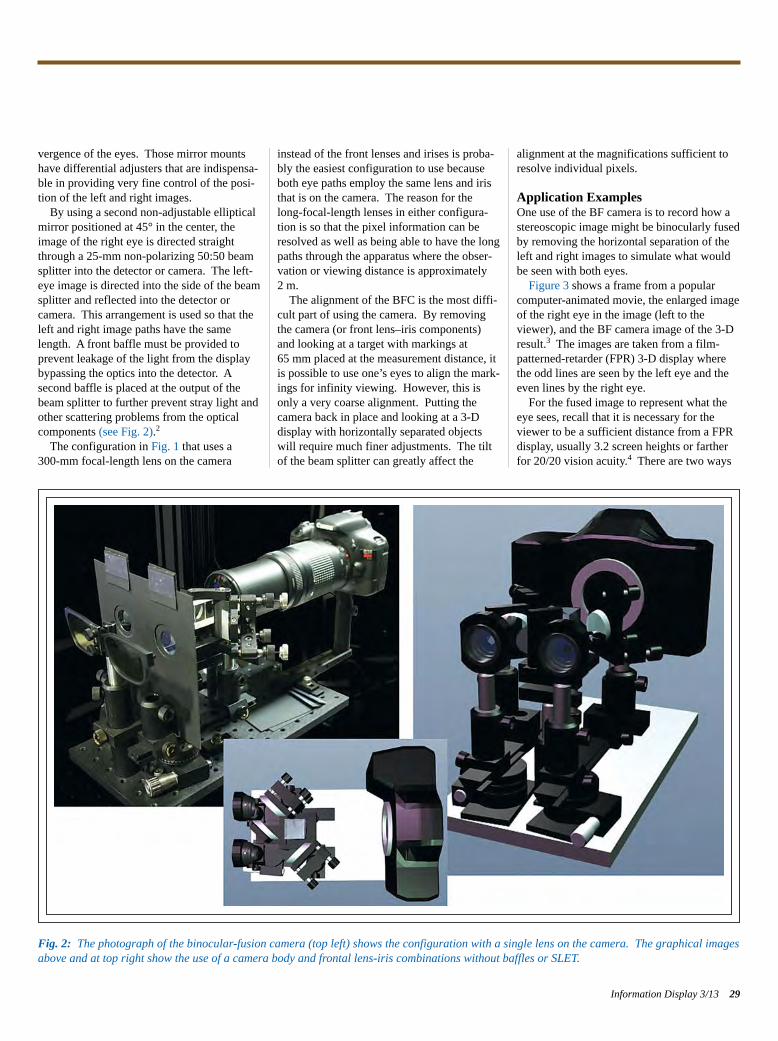
vergence of the eyes. Those mirror mountshave differential adjusters that are indispensa-ble in providing very fine control of the posi-tion of the left and right images. By using a second non-adjustable elliptical
mirror positioned at 45° in the center, theimage of the right eye is directed straightthrough a 25-mm non-polarizing 50:50 beamsplitter into the detector or camera. The left-eye image is directed into the side of the beamsplitter and reflected into the detector or camera. This arrangement is used so that theleft and right image paths have the samelength. A front baffle must be provided toprevent leakage of the light from the displaybypassing the optics into the detector. A second baffle is placed at the output of thebeam splitter to further prevent stray light andother scattering problems from the opticalcomponents (see Fig. 2).2The configuration in Fig. 1 that uses a
300-mm focal-length lens on the camera
instead of the front lenses and irises is proba-bly the easiest configuration to use becauseboth eye paths employ the same lens and iristhat is on the camera. The reason for thelong-focal-length lenses in either configura-tion is so that the pixel information can beresolved as well as being able to have the longpaths through the apparatus where the obser-vation or viewing distance is approximately2 m.The alignment of the BFC is the most diffi-
cult part of using the camera. By removingthe camera (or front lens–iris components)and looking at a target with markings at65 mm placed at the measurement distance, itis possible to use one’s eyes to align the mark-ings for infinity viewing. However, this isonly a very coarse alignment. Putting thecamera back in place and looking at a 3-D display with horizontally separated objectswill require much finer adjustments. The tiltof the beam splitter can greatly affect the
alignment at the magnifications sufficient toresolve individual pixels.
Application ExamplesOne use of the BF camera is to record how astereoscopic image might be binocularly fusedby removing the horizontal separation of theleft and right images to simulate what wouldbe seen with both eyes. Figure 3 shows a frame from a popular
computer-animated movie, the enlarged imageof the right eye in the image (left to theviewer), and the BF camera image of the 3-Dresult.3 The images are taken from a film-patterned-retarder (FPR) 3-D display wherethe odd lines are seen by the left eye and theeven lines by the right eye. For the fused image to represent what the
eye sees, recall that it is necessary for theviewer to be a sufficient distance from a FPRdisplay, usually 3.2 screen heights or fartherfor 20/20 vision acuity.4 There are two ways
Information Display 3/13 29
Fig. 2: The photograph of the binocular-fusion camera (top left) shows the configuration with a single lens on the camera. The graphical imagesabove and at top right show the use of a camera body and frontal lens-iris combinations without baffles or SLET.
Kelley p28-31_Layout 1 4/20/2013 10:19 PM Page 29
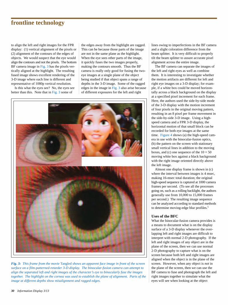
to align the left and right images for the FPRdisplay: (1) vertical alignment of the pixels or(2) alignment of the contours of the edges ofobjects. We would suspect that the eye would align the contours and not the pixels. The bottom BF camera image in Fig. 3 has the pixels ver-tically aligned at the highlight. The resultingfused image shows excellent rendering of the3-D image where each line is different andrepresentative of 1080p vertical resolution. Is this what the eyes see? No, the eyes see
better than this. Note that in Fig. 3 some of
the edges away from the highlight are ragged.This can be because those parts of the imageare not in the same plane as the highlight.When the eye sees other parts of the image, it quickly fuses the two images properly, making the contours smooth. Thus the BFcamera is really only good for fusing the two-eye images at a single plane of the objectbeing studied if that object spans a range ofdepths in the 3-D image. Some of the raggededges in the image in Fig. 3 also arise becauseof different exposures for the left and right
lines owing to imperfections in the BF cameraand a slight coloration difference from thebeam splitter. It is very difficult to properlytilt the beam splitter to assure accurate pixelalignment across the entire image.The BF camera can separate the images of
the left and right eyes as well as combinethem. It is interesting to investigate whetherthe motion artifacts are different for left andright eye images on a 3-D display; for exam-ple, if a white box could be moved horizon-tally across a black background on the displayat a specified pixel increment for each frame.Here, the authors used the side-by-side modeof the 3-D display with the motion incrementof four pixels in the original moving pattern,resulting in an 8 pixel per frame movement inthe side-by-side 3-D image. Using a high-speed camera and a FPR 3-D display, the horizontal motion of that small block can berecorded for both eye images at the sametime. Figure 4 shows (a) the high-speed cam-era in use with the binocular-fusion optics,(b) the pattern on the screen with stationarysmall vertical lines in addition to the movingboxes, and (c) one sequence of the 10 × 50moving white box against a black backgroundwith the right image oriented directly abovethe left image. Almost one display frame is shown in (c)
where the interval between images is 4 msec,making 16-msec total duration; the original high-speed sequence is captured at 1000 camera frames per second. (To see all the processes going on, such as a rolling backlight, the authors generally use from 10,000 to 15,000 framesper second.) The resulting image sequence can be analyzed according to standard methods to determine moving-edge blur profiles.5
Uses of the BFCWhat the binocular-fusion camera provides isa means to document what is on the displaysurface of a 3-D display whenever the over-lapping left and right images are difficult tointerpret with normal 2-D photography. If theleft and right images of any object are in theplane of the screen, then we can use normal 2-D photography to capture what is on thescreen because both left and right images arealigned when the object is in the plane of thescreen. However, when any object is not inthe plane of the screen, then we can use theBF camera to fuse and photograph the left andright images together to simulate what theeyes will see when looking at the object
frontline technology
30 Information Display 3/13
Fig. 3: This frame from the movie Tangled shows an apparent face image in front of the screensurface on a film-patterned-retarder 3-D display. The binocular-fusion camera can attempt toalign the separated left and right images of the character’s eye to binocularly fuse the imagestogether. The highlight on the cornea was used to establish the plane of alignment. Parts of theimage at different depths show misalignment and ragged edges.
Kelley p28-31_Layout 1 4/20/2013 10:19 PM Page 30
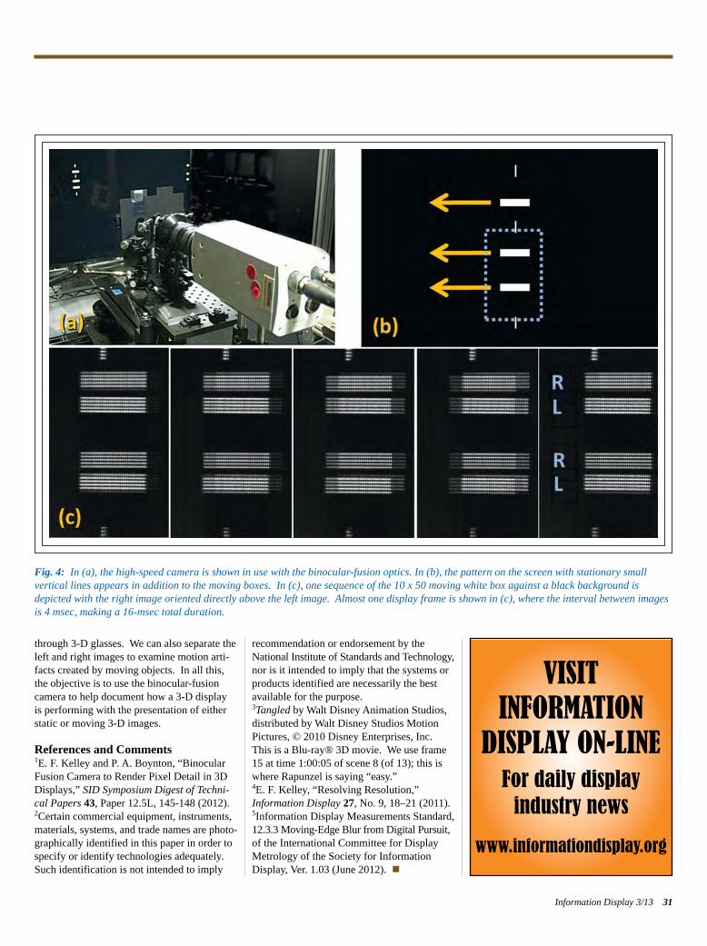
through 3-D glasses. We can also separate theleft and right images to examine motion arti-facts created by moving objects. In all this,the objective is to use the binocular-fusioncamera to help document how a 3-D display is performing with the presentation of eitherstatic or moving 3-D images.
References and Comments 1E. F. Kelley and P. A. Boynton, “BinocularFusion Camera to Render Pixel Detail in 3DDisplays,” SID Symposium Digest of Techni-cal Papers 43, Paper 12.5L, 145-148 (2012).2Certain commercial equipment, instruments,materials, systems, and trade names are photo-graphically identified in this paper in order tospecify or identify technologies adequately.Such identification is not intended to imply
recommendation or endorsement by the National Institute of Standards and Technology, nor is it intended to imply that the systems orproducts identified are necessarily the bestavailable for the purpose. 3Tangled by Walt Disney Animation Studios,distributed by Walt Disney Studios MotionPictures, © 2010 Disney Enterprises, Inc.This is a Blu-ray® 3D movie. We use frame15 at time 1:00:05 of scene 8 (of 13); this iswhere Rapunzel is saying “easy.”4E. F. Kelley, “Resolving Resolution,” Information Display 27, No. 9, 18–21 (2011). 5Information Display Measurements Standard,12.3.3 Moving-Edge Blur from Digital Pursuit,of the International Committee for DisplayMetrology of the Society for Information Display, Ver. 1.03 (June 2012). n
Information Display 3/13 31
Fig. 4: In (a), the high-speed camera is shown in use with the binocular-fusion optics. In (b), the pattern on the screen with stationary small vertical lines appears in addition to the moving boxes. In (c), one sequence of the 10 x 50 moving white box against a black background isdepicted with the right image oriented directly above the left image. Almost one display frame is shown in (c), where the interval between imagesis 4 msec, making a 16-msec total duration.
VISITINFORMATION
DISPLAY ON-LINEFor daily displayindustry news
www.informationdisplay.org
Kelley p28-31_Layout 1 4/20/2013 10:19 PM Page 31
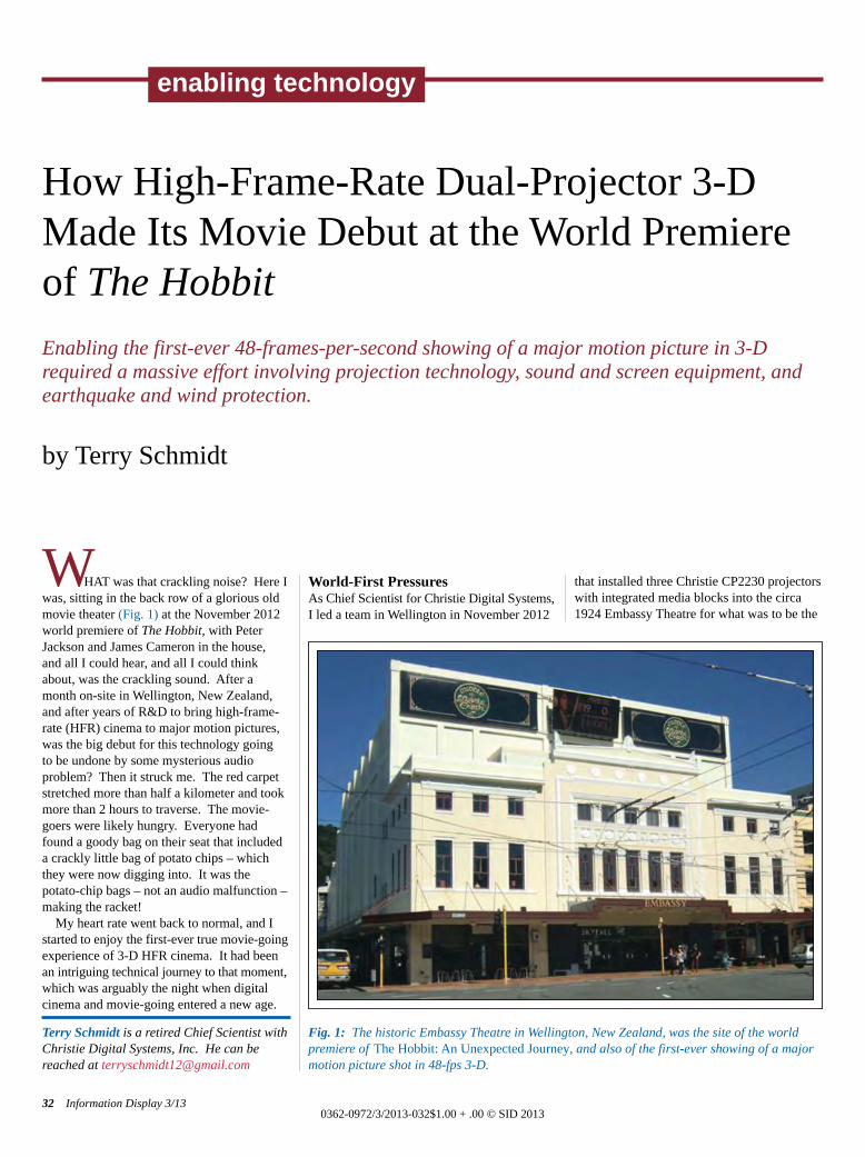
WHAT was that crackling noise? Here Iwas, sitting in the back row of a glorious oldmovie theater (Fig. 1) at the November 2012world premiere of The Hobbit, with PeterJackson and James Cameron in the house, and all I could hear, and all I could thinkabout, was the crackling sound. After a month on-site in Wellington, New Zealand,and after years of R&D to bring high-frame-rate (HFR) cinema to major motion pictures,was the big debut for this technology going to be undone by some mysterious audio problem? Then it struck me. The red carpetstretched more than half a kilometer and tookmore than 2 hours to traverse. The movie-goers were likely hungry. Everyone hadfound a goody bag on their seat that includeda crackly little bag of potato chips – whichthey were now digging into. It was thepotato-chip bags – not an audio malfunction –making the racket!My heart rate went back to normal, and I
started to enjoy the first-ever true movie-going experience of 3-D HFR cinema. It had been an intriguing technical journey to that moment, which was arguably the night when digitalcinema and movie-going entered a new age.
World-First PressuresAs Chief Scientist for Christie Digital Systems,I led a team in Wellington in November 2012
that installed three Christie CP2230 projectorswith integrated media blocks into the circa1924 Embassy Theatre for what was to be the
How High-Frame-Rate Dual-Projector 3-DMade Its Movie Debut at the World Premiereof The HobbitEnabling the first-ever 48-frames-per-second showing of a major motion picture in 3-Drequired a massive effort involving projection technology, sound and screen equipment, andearthquake and wind protection.
by Terry Schmidt
Terry Schmidt is a retired Chief Scientist withChristie Digital Systems, Inc. He can bereached at [email protected]
32 Information Display 3/130362-0972/3/2013-032$1.00 + .00 © SID 2013
enabling technology
Fig. 1: The historic Embassy Theatre in Wellington, New Zealand, was the site of the worldpremiere of The Hobbit: An Unexpected Journey, and also of the first-ever showing of a majormotion picture shot in 48-fps 3-D.
Schmidt p32-35_Layout 1 4/20/2013 10:24 PM Page 32
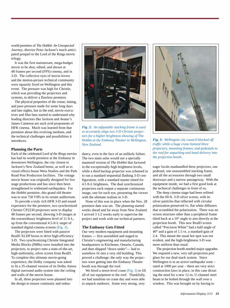
world premiere of The Hobbit: An UnexpectedJourney, director Peter Jackson’s much antici-pated prequel to the Lord of the Rings movietrilogy.It was the first mainstream, mega-budget
movie to be shot, edited, and shown at 48 frames per second (FPS) cinema, and in 3-D. The collective eyes of movie-lovers and the motion-picture technical communitywere squarely fixed on Wellington and thisevent. The pressure was high for Christie,which was providing the projectors and systems, to deliver a flawless premiere.The physical properties of the venue, timing,
and pure pressure made for some long daysand late nights, but in the end, movie execu-tives and film fans started to understand whyleading directors like Jackson and Avatar’sJames Cameron are such avid proponents ofHFR cinema. Much was learned from thatpremiere about this evolving medium, and the technical challenges and possibilities itintroduces.
Planning the PartsEach of the celebrated Lord of the Rings movies has had its world premiere at the Embassy indowntown Wellington, the city closest toJackson’s New Zealand home, as well as tovisual effects house Weta Studios and the ParkRoad Post Production facilities. The vintagemovie house was originally designed for livestage productions and has since then beenstrengthened to withstand earthquakes. Forthe Hobbit premiere, this grand old theaterwas to seat 758 VIPs in its ornate auditorium.To provide a truly rich HFR 3-D and sound
experience for the premiere, two synchronizedChristie CP2230 projectors were to display 48 frames per second, showing 3-D images atthe extraordinary brightness level of 11 ft-L,up from the conventional 4.5-ft-L target ofstandard digital-cinema screens (Fig. 2).The projectors were fitted with passive
RealD XLDP boxes to drive high-efficiency3-D. Two synchronizing Christie IntegratedMedia Blocks (IMBs) were installed into theprojectors, to project onto a state-of-the-art,high-uniformity, silver screen from RealD. To complete this ultimate movie-going experience, the Dolby company was asked to fit a 35-channel version of its Dolby Atmosdigital surround audio system into the ceilingand walls of the movie house.In all, three projectors were planned into
the design to ensure continuity and redun-
dancy, even in the face of an unlikely failure.The two main units would use a speciallymastered version of The Hobbit that factoredin the exceptionally high brightness levels,while a third backup projector was schemed into run a standard sequential flashing 3-D con-figuration, with a standard master timed for4.5 ft-L brightness. The dual synchronizedprojectors each output a separate continuousimage, one for each eye, presenting the viewerwith the ultimate realism in 3-D.None of this was in place when the Nov. 28
premiere date was set. The planning startedweeks ahead and far away from New Zealand.I arrived 3 1/2 weeks early to supervise theproject and work with our technical partners.
The Embassy Gets FittedOur very modern equipment and mountingframes — first assembled and staged inChristie’s engineering and manufacturingheadquarters in Kitchener, Ontario, Canada,and then shipped “down under”— had tosomehow fit into a very old building. Thisproved a challenge: the only way the projec-tors were getting into the Embassy Theatrebooth was through the roof. We hired a street-level crane (Fig. 3) to lift
all of our equipment to the roof. Thankfully,we had sunshine on crane day and were ableto unpack outdoors. Some very strong, very
eager locals manhandled three projectors, onepedestal, one unassembled stacking frame,and all the accessories through two smalldoorways and a narrow passageway. With theequipment inside, we had a first good look atthe technical challenges in front of us.The deep cinema stage had been refitted
with the 60-ft. 3-D silver screen, with its silver particles that reflected with circularpolarization preserved vs. flat white diffusersthat scrambled the polarization. There was noscreen structure other than a peripheral frametilted back at a 10° angle to aim directly at theprojection booth. This new RealD screencalled “Precision White” had a half-angle of40° and a gain of 1.5 vs. a standard gain of2.4. This meant the usual hot spot was notevident, and the high-brightness 3-D wasmore uniform than usual.The projection booth needed major upgrades.
We required a new, very tall projection portglass for our dual-stack system. SinceWellington is in an active earthquake zone –rated at 1000 per year – there are very strictconstruction laws in place, in this case dictat-ing the need for a new 12-in. U-channel steelbeam to be bolted through the wall over awindow. This was brought on by having to
Information Display 3/13 33
Fig. 2: An adjustable stacking frame is usedto accurately align two 3-D Christie projec-tors for a higher brightness showing of TheHobbit at the Embassy Theater in Wellington,New Zealand.
Fig. 3: Wellington city council blocked offtraffic while a huge crane hoisted three projectors, mounting frames, and pedestals tothe roof for unpacking and hand delivery intothe projection booth.
Schmidt p32-35_Layout 1 4/20/2013 10:24 PM Page 33
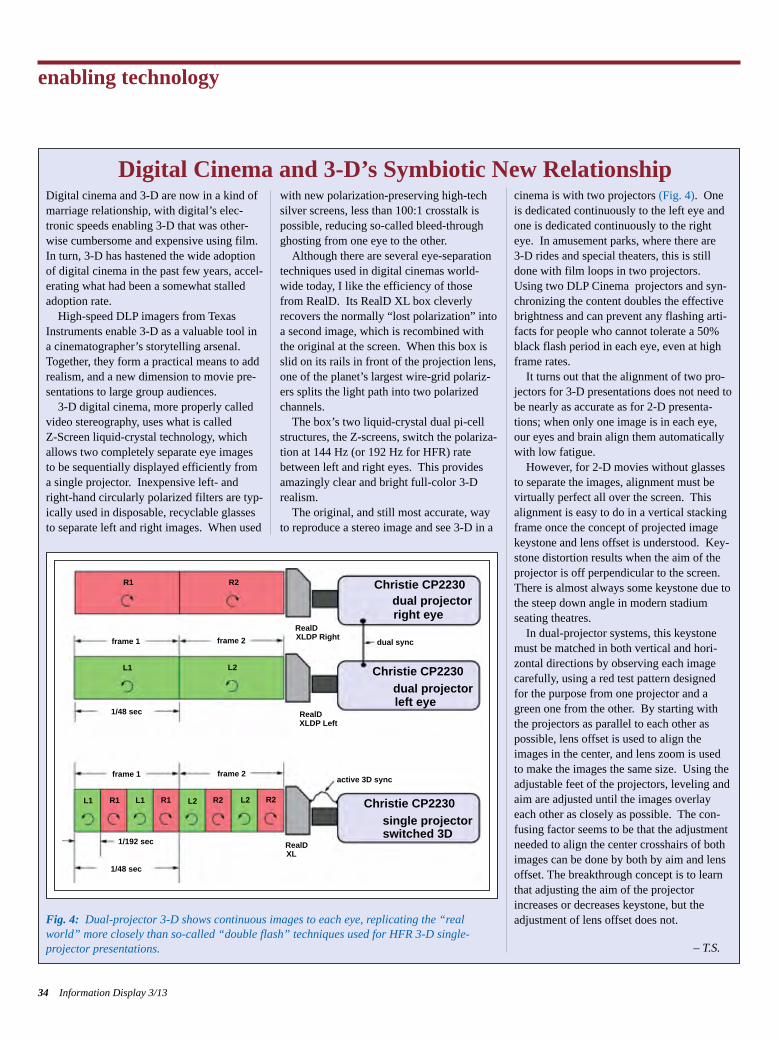
enabling technology
34 Information Display 3/13
Digital cinema and 3-D are now in a kind ofmarriage relationship, with digital’s elec-tronic speeds enabling 3-D that was other-wise cumbersome and expensive using film.In turn, 3-D has hastened the wide adoptionof digital cinema in the past few years, accel-erating what had been a somewhat stalledadoption rate. High-speed DLP imagers from Texas
Instruments enable 3-D as a valuable tool ina cinematographer’s storytelling arsenal.Together, they form a practical means to addrealism, and a new dimension to movie pre-sentations to large group audiences.3-D digital cinema, more properly called
video stereography, uses what is called Z-Screen liquid-crystal technology, whichallows two completely separate eye imagesto be sequentially displayed efficiently froma single projector. Inexpensive left- andright-hand circularly polarized filters are typ-ically used in disposable, recyclable glassesto separate left and right images. When used
with new polarization-preserving high-techsilver screens, less than 100:1 crosstalk ispossible, reducing so-called bleed-throughghosting from one eye to the other.Although there are several eye-separation
techniques used in digital cinemas world-wide today, I like the efficiency of thosefrom RealD. Its RealD XL box cleverlyrecovers the normally “lost polarization” intoa second image, which is recombined withthe original at the screen. When this box isslid on its rails in front of the projection lens,one of the planet’s largest wire-grid polariz-ers splits the light path into two polarizedchannels. The box’s two liquid-crystal dual pi-cell
structures, the Z-screens, switch the polariza-tion at 144 Hz (or 192 Hz for HFR) ratebetween left and right eyes. This providesamazingly clear and bright full-color 3-Drealism.The original, and still most accurate, way
to reproduce a stereo image and see 3-D in a
cinema is with two projectors (Fig. 4). Oneis dedicated continuously to the left eye andone is dedicated continuously to the righteye. In amusement parks, where there are 3-D rides and special theaters, this is stilldone with film loops in two projectors.Using two DLP Cinema projectors and syn-chronizing the content doubles the effectivebrightness and can prevent any flashing arti-facts for people who cannot tolerate a 50%black flash period in each eye, even at highframe rates.It turns out that the alignment of two pro-
jectors for 3-D presentations does not need tobe nearly as accurate as for 2-D presenta-tions; when only one image is in each eye,our eyes and brain align them automaticallywith low fatigue. However, for 2-D movies without glasses
to separate the images, alignment must bevirtually perfect all over the screen. Thisalignment is easy to do in a vertical stackingframe once the concept of projected imagekeystone and lens offset is understood. Key-stone distortion results when the aim of theprojector is off perpendicular to the screen.There is almost always some keystone due tothe steep down angle in modern stadiumseating theatres. In dual-projector systems, this keystone
must be matched in both vertical and hori-zontal directions by observing each imagecarefully, using a red test pattern designedfor the purpose from one projector and agreen one from the other. By starting withthe projectors as parallel to each other aspossible, lens offset is used to align theimages in the center, and lens zoom is usedto make the images the same size. Using theadjustable feet of the projectors, leveling andaim are adjusted until the images overlayeach other as closely as possible. The con-fusing factor seems to be that the adjustmentneeded to align the center crosshairs of bothimages can be done by both by aim and lensoffset. The breakthrough concept is to learnthat adjusting the aim of the projectorincreases or decreases keystone, but theadjustment of lens offset does not.
– T.S.
Digital Cinema and 3-D’s Symbiotic New Relationship
Fig. 4: Dual-projector 3-D shows continuous images to each eye, replicating the “realworld” more closely than so-called “double flash” techniques used for HFR 3-D single-projector presentations.
R1
R1 R1
R2
L2L1
frame 1 frame 2
1/48 sec
1/48 sec
1/192 sec
RealD
RealD
RealDXL
active 3D sync
dual sync
Christie CP2230
Christie CP2230
Christie CP2230dual projector
dual projector
single projector
right eye
left eye
switched 3D
XLDP Right
XLDP Left
frame 2frame 1
L1 L1 L2L2 R2 R2
Schmidt p32-35_Layout 1 4/20/2013 10:24 PM Page 34
cut a larger port opening for the dual projec-tors in a solid concrete wall, a process thatremoved some internal steel reinforcement.The sheet of noise-reducing port glass
arrived broken in half. With no time to get areplacement, we were forced to make do.Fortunately, the crack was almost horizontaland centered, so by using the adjustable extru-sions of the stacking frame, we were able toadjust the two beams from the top RealD XLsystem to clear over the crack, and the lowerprojector to clear under. It worked! We also had to upgrade the heat-extraction
system, the existing system having been calculated by city engineers to be inadequateto handle the new Christie outputs. Wemounted three huge, low-noise heat extractorson the ceiling and used two louvered windowboxes that exhausted to the roof area throughthe booth outside wall. This was by design, to prevent back drafts from the notoriously high winds of Wellington. The third-party NetworkAttached Storage (NAS) system – betweenunplanned sleep modes and rebuild processesand passwords – took some finagling, but wetamed it in time for the premiere.
Team EffortThe HFR speeds necessitated the installationof integrated media blocks (IMBs) into thecard cage of each projector. This allowed datato be connected to the highly parallel internalbackplane of the projector. Each IMB wasconnected to its respective NAS device via aCAT6 Ethernet cable, where the content wasstored in a Raid 5 configuration of four 1-terabyte drives. A small coax cable con-nected the two projectors to each other, sospecialized dual-projector software could keepthe left- and right-eye images in perfect synchronization.All-electronic systems possible were also
connected to battery backed-up UPS powersupplies, in case of a short power outage thatwould require a long microprocessor re-bootdelay. This included all three projector signalelectronics, and three of the six redundantNAS power supplies, as well as the DolbyAtmos processor. In this way, a small powerhiccup would require only a fast lamp re-strike in order for the show to carry on. Ultimately, this hard work led to a very successful first showing of the film, and thispowerful new cinema technology. At thispoint, I offer a closer look at the progress ofHFR.
HFR’s Big MomentThe worldwide conversion of film cinemas todigital has seen many bumps along the road.Initially, hardened film buffs missed the shakyand grainy film look they grew up with, and purists nostalgically yearned for the simplicity of output from the old mechanical film projectors. With the advances in DLP Cinema, speeds
fast enough to support 3-D with a single projector became possible. The frame rate,however, remained at 24 frames per second(fps) to match the look and feel of film. Evenhome TV exceeded film with its 30 fps, andwith the popularity of HD digital TV, mosthome theaters have now reached 60 framesprogressive for HDTV broadcasts.Despite all these advances, digital cinema
frame rates seemed stuck at 24 fps. All thatstarted to change 2 years ago, when Jackson,Cameron, and other influential directorsstarted exploring what a faster frame ratewould do for cinematic storytelling. Cameron showed a specially shot series of
higher-frame-rate 3-D test clips at Cinemacon2011 in Las Vegas. These consisted ofmedieval feast and fighting sequences shot at24, 48, and 60 fps for the cinema industry’stechnical community at the Colosseum at Caesar’s Palace. The demo was supported byfour projectors set up for fast-switching audi-ence evaluation among the three frame rates.This content demonstrated that high panningspeeds and fast-action sequences could benefitin clarity at the higher frame rates of 48 or 60 fps versus the standard film rate of 24 fps. The demonstration was a huge success, as
everyone could see that 48 fps delivered sig-nificant improvements. Jerky motion artifacts disappeared and action scenes flowed smoothly. There was a discernible further improvementin going to 60 fps, but the difference from 48 fps was relatively small. A year later, again at Cinemacon, Jackson
showed an unfinished 10-minute excerpt fromThe Hobbit at 48 fps using Christie projectors.The excerpt drew a lot of controversy fromfilm-buff bloggers who objected to the hyper-realism and missed the soft, classic “filmlook.” Many thought it looked more likeactors on a stage because the 3-D effect andincreased motion accuracy and increased clarity paralleled real life. This is called the‘presidium effect’ – presidium being the namefor a stage surround. Some extreme comments likened it to a TV
soap-opera look, which “cheapened” the
medium. Jackson counter-argued that theshort, unfinished clip did not allow enoughtime to draw viewers into the story to then for-get about the projection medium and enjoy therealism of the movie. It did not dissuade himfrom finishing and releasing the film in HFR.The experience in some ways mirrored the
transition from standard-TV to HDTV resolu-tion. As with HDTV, the acceptance of thestrong advantages of HFR’s realism, andincreased detail in both fast motion andscenery, will take some time, but is predictedby many to be inevitable. Cameron has prom-ised both of the Avatar sequels to be in HFR,although at the time of writing he has notdeclared whether it will be 48 or 60 fps.Having seen the final product, I am happy
to report The Hobbit: An Unexpected Journeyhas met mostly with encouraging acceptancein its newly introduced HFR format in almost900 screens worldwide, as well as standard 24-fps 3-D showings. Early reports of nauseafrom too much HFR realism in the actionscenes were replaced with reports of breath-taking scenery and very realistic close-upsthat perfectly conveyed the story and charac-ters. According to many, HFR cinema is hereto stay. n
Information Display 3/13 35
J O I N S I DWe invite you to join SID to participate in shaping the future development of:
• Display technologies and display-relatedproducts
• Materials and components for displays anddisplay applications
• Manufacturing processes and equipment
• New markets and applications
In every specialty you will find SID members as leading contributors to their profession.
http://www.sid.org/Membership.aspx
Schmidt p32-35_Layout 1 4/20/2013 10:24 PM Page 35
DISPLAY DEVELOPERS now haveextraordinary opportunities for advancing performance. They can create displays thatapproach the limits of human perception (inresolution) and produce more than enoughluminance in most cases. Displays can alsooffer a much larger color gamut – a perform-ance characteristic that has lagged behindgains in resolution and luminance – thanks tonew display architectures and technologiessuch as quantum dots and organic light-emittingdiodes (OLEDs).
However, even though manufacturers havethe technical capability to do so, most do notproduce displays that provide the highest levels of resolution, luminance, and colorgamut. (Similarly, automakers do not giveevery vehicle top-of-the-line horsepower andinterior styling.) Instead, they might decide tomoderate performance characteristics to meetconsumers’ cost constraints. They recognizethe consumers’ and regulators’ concerns about
energy consumption. And they take advan-tage of consumers’ color and resolutionexpectations, which do not require a perfectlyfaithful representation of reality.
The impact of some of these tradeoffs canbe calculated with relative ease. For example,if a product developer were considering areduction in backlight performance resultingin reduced display luminance, the impact ondisplay performance in exchange for cost savings could be measured using readilyavailable tools. Potential improvements inenergy consumption would also be easy toquantify.
Measuring the impact of display character-istics on consumers’ perceptions of quality ismore difficult. It is harder still to gauge thechange in consumers’ attitudes if a reductionin one performance attribute – luminance, forexample – is accompanied by an improvementin another, such as color or resolution.
Large-scale consumer surveys could, in theory, provide the detailed information aboutconsumer preferences that developers wouldlike to have when considering tradeoffs; however, such research is expensive. Further-more, research on consumer preferences isoften useful for only short periods; key per-formance characteristics improve rapidly andconsumer expectations change with them.
(What was a desirable resolution in 2007 wassubpar in 2010.) Not surprisingly, few large-scale studies of consumer preferences havebeen undertaken.
As an alternative, some researchers havepursued computational models of consumerpreferences, such as P. G. J. Barten’s SquareRoot Integral (SQRI) metric. First publishedin 1987, the SQRI calculates expected viewer preferences for size, resolution, and luminance.1SQRI’s value is limited, however, in that itdoes not consider color gamut and contrast.
Recently, the authors and other researchersat 3M developed the Perceptual Quality Metric (PQM), a new computational modelbased in part on the SQRI. The goal of thismetric is to predict the subjective quality of adisplay, not the fidelity of the images renderedon it. PQM calculates expected viewer per-ceptions of quality based on viewing distance,display size, resolution, luminance, and colorgamut. By using this tool, product developerscan now quantify the perceptual qualityimprovements in products based on changesin display specifications. These assessmentscan then be used to guide the inevitable trade-offs that are made in display design or, moreintriguingly, drive toward a display thatachieves levels of perceived quality heretounforeseen.
PQM: A Quantitative Tool for Evaluating Decisions in Display DesignDisplay manufacturers must continually make decisions about device performance withregard to such characteristics as resolution, luminance, and color. 3M has developed a new tool that enables product developers to forecast how these design factors affect users’perceptions of quality.
by Jennifer F. Schumacher, John Van Derlofske, Brian Stankiewicz,Dave Lamb, and Art Lathrop
Jennifer F. Schumacher and Brian Stankiewiczare with 3M Company’s Software, Electronics,and Mechanical Systems Laboratory. JohnVan Derlofske, Dave Lamb, and Art Lathropare with 3M Company’s Optical Systems Division. They can be reached through 3M’swebsite at www.3m.com/displayfilms.
36 Information Display 3/130362-0972/3/2013-036$1.00 + .00 © SID 2013
enabling technology
Schumacher p36-41_Layout 1 4/20/2013 10:35 PM Page 36
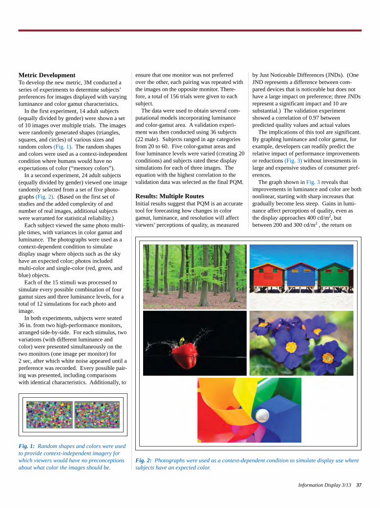
Metric DevelopmentTo develop the new metric, 3M conducted aseries of experiments to determine subjects’preferences for images displayed with varyingluminance and color gamut characteristics.
In the first experiment, 14 adult subjects(equally divided by gender) were shown a setof 10 images over multiple trials. The imageswere randomly generated shapes (triangles,squares, and circles) of various sizes and random colors (Fig. 1). The random shapesand colors were used as a context-independentcondition where humans would have noexpectations of color (“memory colors”).
In a second experiment, 24 adult subjects(equally divided by gender) viewed one imagerandomly selected from a set of five photo-graphs (Fig. 2). (Based on the first set ofstudies and the added complexity of and number of real images, additional subjectswere warranted for statistical reliability.)
Each subject viewed the same photo multi-ple times, with variances in color gamut andluminance. The photographs were used as acontext-dependent condition to simulate display usage where objects such as the skyhave an expected color; photos includedmulti-color and single-color (red, green, andblue) objects.
Each of the 15 stimuli was processed tosimulate every possible combination of fourgamut sizes and three luminance levels, for atotal of 12 simulations for each photo andimage.
In both experiments, subjects were seated36 in. from two high-performance monitors,arranged side-by-side. For each stimulus, twovariations (with different luminance andcolor) were presented simultaneously on thetwo monitors (one image per monitor) for 2 sec, after which white noise appeared until apreference was recorded. Every possible pair-ing was presented, including comparisonswith identical characteristics. Additionally, to
ensure that one monitor was not preferredover the other, each pairing was repeated withthe images on the opposite monitor. There-fore, a total of 156 trials were given to eachsubject.
The data were used to obtain several com-putational models incorporating luminanceand color-gamut area. A validation experi-ment was then conducted using 36 subjects(22 male). Subjects ranged in age categoriesfrom 20 to 60. Five color-gamut areas andfour luminance levels were varied (creating 20conditions) and subjects rated these displaysimulations for each of three images. Theequation with the highest correlation to thevalidation data was selected as the final PQM.
Results: Multiple Routes Initial results suggest that PQM is an accuratetool for forecasting how changes in colorgamut, luminance, and resolution will affectviewers’ perceptions of quality, as measured
by Just Noticeable Differences (JNDs). (OneJND represents a difference between com-pared devices that is noticeable but does nothave a large impact on preference; three JNDsrepresent a significant impact and 10 are substantial.) The validation experimentshowed a correlation of 0.97 between predicted quality values and actual values
The implications of this tool are significant.By graphing luminance and color gamut, forexample, developers can readily predict therelative impact of performance improvementsor reductions (Fig. 3) without investments inlarge and expensive studies of consumer pref-erences.
The graph shown in Fig. 3 reveals thatimprovements in luminance and color are bothnonlinear, starting with sharp increases thatgradually become less steep. Gains in lumi-nance affect perceptions of quality, even asthe display approaches 400 cd/m2, butbetween 200 and 300 cd/m2 , the return on
Information Display 3/13 37
Fig. 2: Photographs were used as a context-dependent condition to simulate display use wheresubjects have an expected color.
Fig. 1: Random shapes and colors were usedto provide context-independent imagery forwhich viewers would have no preconceptionsabout what color the images should be.
Schumacher p36-41_Layout 1 4/20/2013 10:35 PM Page 37
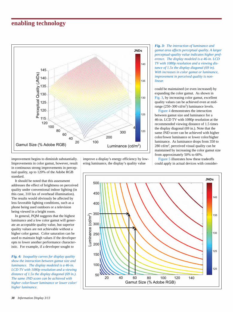
improvement begins to diminish substantially.Improvements in color gamut, however, resultin continuous strong improvements in percep-tual quality, up to 120% of the Adobe RGBstandard.
It should be noted that this assessmentaddresses the effect of brightness on perceivedquality under conventional indoor lighting (inthis case, 310 lux of overhead illumination).The results would obviously be affected byless favorable lighting conditions, such as aphone being used outdoors or a televisionbeing viewed in a bright room.
In general, PQM suggests that the highestluminance and a low color gamut will gener-ate an acceptable quality value, but superiorquality values are not achievable without ahigher color gamut. Color saturation can beused to maintain high values if the developeropts to lower another performance character-istic. For example, if a developer sought to
improve a display’s energy efficiency by low-ering luminance, the display’s quality value
could be maintained (or even increased) byexpanding the color gamut. As shown in Fig. 3, by increasing color gamut, excellentquality values can be achieved even at mid-range (250–300 cd/m2) luminance levels.
Figure 4 demonstrates the interactionbetween gamut size and luminance for a 46-in. LCD TV with 1080p resolution at therecommended viewing distance of 1.5 timesthe display diagonal (69 in.). Note that thesame JND score can be achieved with highercolor/lower luminance or lower color/higherluminance. As luminance drops from 350 to280 cd/m2, perceived visual quality can bemaintained by increasing the color gamut sizefrom approximately 50% to 60%.
Figure 5 illustrates how these tradeoffscould apply in actual devices with consider-
enabling technology
38 Information Display 3/13
Fig. 3: The interaction of luminance andgamut area affects perceptual quality. A larger perceptual-quality value indicates higher pref-erence. The display modeled is a 46-in. LCDTV with 1080p resolution and a viewing dis-tance of 1.5x the display diagonal (69 in).With increases in color gamut or luminance,improvement in perceived quality is non-linear.
Fig. 4: Isoquality curves for display qualityshow the interaction between gamut size and luminance. The display modeled is a 46-in.LCD TV with 1080p resolution and a viewing distance of 1.5x the display diagonal (69 in.).The same JND score can be achieved withhigher color/lower luminance or lower color/higher luminance.
Gamut Size (% Adobe RGB)
145
135
130
125
120
120100
100200
3004
120
125
130
135
140
JNDs
120
140Gamut Size (% Adobe RGB)
Lum
inan
ce (c
d/m
2 )
100 12080604050
100
150
200
250
300
350
400
450
500
20
125
130
135
140
JNDs
8060
4020
115
140
Per
cept
ual Q
ualit
y (J
ND
s)
Luminance (cd/m2)
Schumacher p36-41_Layout 1 4/20/2013 10:35 PM Page 38
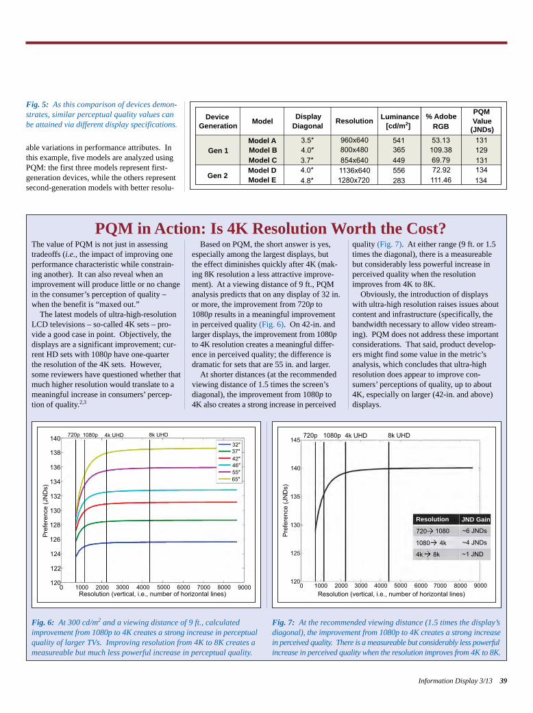
able variations in performance attributes. Inthis example, five models are analyzed usingPQM: the first three models represent first-generation devices, while the others representsecond-generation models with better resolu-
Information Display 3/13 39
Fig. 5: As this comparison of devices demon-strates, similar perceptual quality values can be attained via different display specifications.
The value of PQM is not just in assessingtradeoffs (i.e., the impact of improving oneperformance characteristic while constrain-ing another). It can also reveal when animprovement will produce little or no changein the consumer’s perception of quality –when the benefit is “maxed out.”
The latest models of ultra-high-resolutionLCD televisions – so-called 4K sets – pro-vide a good case in point. Objectively, thedisplays are a significant improvement; cur-rent HD sets with 1080p have one-quarterthe resolution of the 4K sets. However,some reviewers have questioned whether thatmuch higher resolution would translate to ameaningful increase in consumers’ percep-tion of quality.2,3
Based on PQM, the short answer is yes,especially among the largest displays, but the effect diminishes quickly after 4K (mak-ing 8K resolution a less attractive improve-ment). At a viewing distance of 9 ft., PQManalysis predicts that on any display of 32 in.or more, the improvement from 720p to1080p results in a meaningful improvementin perceived quality (Fig. 6). On 42-in. and larger displays, the improvement from 1080pto 4K resolution creates a meaningful differ-ence in perceived quality; the difference isdramatic for sets that are 55 in. and larger.
At shorter distances (at the recommendedviewing distance of 1.5 times the screen’sdiagonal), the improvement from 1080p to 4K also creates a strong increase in perceived
quality (Fig. 7). At either range (9 ft. or 1.5times the diagonal), there is a measureablebut considerably less powerful increase inperceived quality when the resolutionimproves from 4K to 8K.
Obviously, the introduction of displayswith ultra-high resolution raises issues aboutcontent and infrastructure (specifically, thebandwidth necessary to allow video stream-ing). PQM does not address these importantconsiderations. That said, product develop-ers might find some value in the metric’sanalysis, which concludes that ultra-high resolution does appear to improve con-sumers’ perceptions of quality, up to about4K, especially on larger (42-in. and above)displays.
PQM in Action: Is 4K Resolution Worth the Cost?
Fig. 6: At 300 cd/m2 and a viewing distance of 9 ft., calculated improvement from 1080p to 4K creates a strong increase in perceptual quality of larger TVs. Improving resolution from 4K to 8K creates ameasureable but much less powerful increase in perceptual quality.
Fig. 7: At the recommended viewing distance (1.5 times the display’s diagonal), the improvement from 1080p to 4K creates a strong increase in perceived quality. There is a measureable but considerably less powerfulincrease in perceived quality when the resolution improves from 4K to 8K.
DeviceGeneration Model Display
Diagonal Resolution % AdobeRGB
PQMValue
(JNDs)
Gen 1
Gen 2
Model AModel BModel CModel DModel E
3.5″4.0″3.7″
4.8″ 1280x7201136x640854x640800x480960x640 541
365449556283
53.13109.3869.7972.92111.46
131129131134134
4.0″
Luminance[cd/m2]
140 720p 1080p 4k UHD 8k UHD 720p145
140
135
130
125
1200
1080p 4k UHD 8k UHD32″37″42″46″55″65″
138
136
134
132
130
128
126
124
122
1200 1000 2000 3000 4000 5000 6000 7000 8000 9000 1000 2000 3000 4000 5000 6000 7000 8000 9000
Resolution (vertical, i.e., number of horizontal lines) Resolution (vertical, i.e., number of horizontal lines)
Pre
fere
nce
(JN
Ds)
Pre
fere
nce
(JN
Ds)
Resolution
720 1080
1080
4k
4k
8k
~6 JNDs
~4 JNDs
~1 JND
JND Gain
Schumacher p36-41_Layout 1 4/20/2013 10:35 PM Page 39
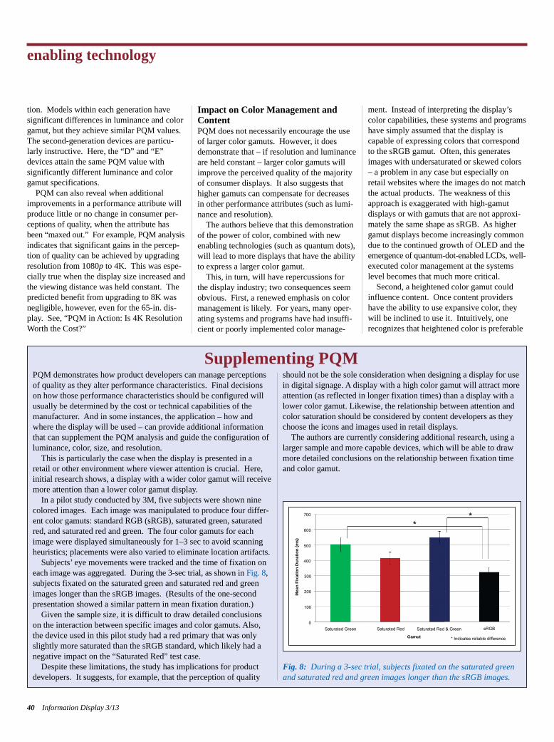
tion. Models within each generation have significant differences in luminance and colorgamut, but they achieve similar PQM values.The second-generation devices are particu-larly instructive. Here, the “D” and “E”devices attain the same PQM value with significantly different luminance and colorgamut specifications.
PQM can also reveal when additionalimprovements in a performance attribute willproduce little or no change in consumer per-ceptions of quality, when the attribute hasbeen “maxed out.” For example, PQM analysisindicates that significant gains in the percep-tion of quality can be achieved by upgradingresolution from 1080p to 4K. This was espe-cially true when the display size increased andthe viewing distance was held constant. Thepredicted benefit from upgrading to 8K wasnegligible, however, even for the 65-in. dis-play. See, “PQM in Action: Is 4K ResolutionWorth the Cost?”
Impact on Color Management andContent PQM does not necessarily encourage the useof larger color gamuts. However, it doesdemonstrate that – if resolution and luminanceare held constant – larger color gamuts willimprove the perceived quality of the majorityof consumer displays. It also suggests thathigher gamuts can compensate for decreasesin other performance attributes (such as lumi-nance and resolution).
The authors believe that this demonstrationof the power of color, combined with newenabling technologies (such as quantum dots),will lead to more displays that have the abilityto express a larger color gamut.
This, in turn, will have repercussions forthe display industry; two consequences seemobvious. First, a renewed emphasis on colormanagement is likely. For years, many oper-ating systems and programs have had insuffi-cient or poorly implemented color manage-
ment. Instead of interpreting the display’scolor capabilities, these systems and programshave simply assumed that the display is capable of expressing colors that correspondto the sRGB gamut. Often, this generatesimages with undersaturated or skewed colors– a problem in any case but especially onretail websites where the images do not matchthe actual products. The weakness of thisapproach is exaggerated with high-gamut displays or with gamuts that are not approxi-mately the same shape as sRGB. As highergamut displays become increasingly commondue to the continued growth of OLED and the emergence of quantum-dot-enabled LCDs, well-executed color management at the systemslevel becomes that much more critical.
Second, a heightened color gamut couldinfluence content. Once content providershave the ability to use expansive color, theywill be inclined to use it. Intuitively, one recognizes that heightened color is preferable
enabling technology
40 Information Display 3/13
PQM demonstrates how product developers can manage perceptionsof quality as they alter performance characteristics. Final decisionson how those performance characteristics should be configured willusually be determined by the cost or technical capabilities of themanufacturer. And in some instances, the application – how andwhere the display will be used – can provide additional informationthat can supplement the PQM analysis and guide the configuration ofluminance, color, size, and resolution.
This is particularly the case when the display is presented in aretail or other environment where viewer attention is crucial. Here,initial research shows, a display with a wider color gamut will receivemore attention than a lower color gamut display.
In a pilot study conducted by 3M, five subjects were shown ninecolored images. Each image was manipulated to produce four differ-ent color gamuts: standard RGB (sRGB), saturated green, saturatedred, and saturated red and green. The four color gamuts for eachimage were displayed simultaneously for 1–3 sec to avoid scanningheuristics; placements were also varied to eliminate location artifacts.
Subjects’ eye movements were tracked and the time of fixation on each image was aggregated. During the 3-sec trial, as shown in Fig. 8, subjects fixated on the saturated green and saturated red and greenimages longer than the sRGB images. (Results of the one-secondpresentation showed a similar pattern in mean fixation duration.)
Given the sample size, it is difficult to draw detailed conclusionson the interaction between specific images and color gamuts. Also,the device used in this pilot study had a red primary that was onlyslightly more saturated than the sRGB standard, which likely had anegative impact on the “Saturated Red” test case.
Despite these limitations, the study has implications for productdevelopers. It suggests, for example, that the perception of quality
should not be the sole consideration when designing a display for usein digital signage. A display with a high color gamut will attract moreattention (as reflected in longer fixation times) than a display with alower color gamut. Likewise, the relationship between attention andcolor saturation should be considered by content developers as theychoose the icons and images used in retail displays.
The authors are currently considering additional research, using alarger sample and more capable devices, which will be able to drawmore detailed conclusions on the relationship between fixation timeand color gamut.
Supplementing PQM
Fig. 8: During a 3-sec trial, subjects fixated on the saturated greenand saturated red and green images longer than the sRGB images.
sRGB
Gamut
Saturated Red & GreenSaturated RedSaturated Green0
100
200
300
400
500
600
700
**
Mea
n Fi
xatio
n D
urat
ion
(ms)
* Indicates reliable difference
Schumacher p36-41_Layout 1 4/20/2013 10:35 PM Page 40
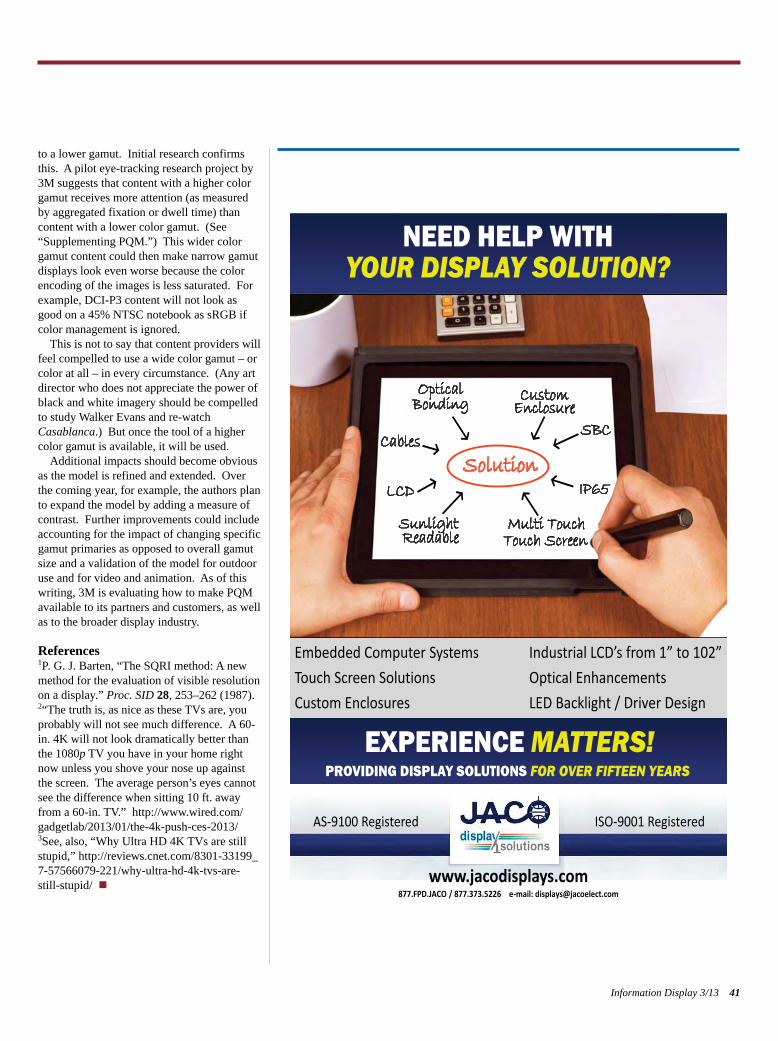
to a lower gamut. Initial research confirmsthis. A pilot eye-tracking research project by3M suggests that content with a higher colorgamut receives more attention (as measuredby aggregated fixation or dwell time) thancontent with a lower color gamut. (See “Supplementing PQM.”) This wider colorgamut content could then make narrow gamutdisplays look even worse because the colorencoding of the images is less saturated. Forexample, DCI-P3 content will not look asgood on a 45% NTSC notebook as sRGB ifcolor management is ignored.
This is not to say that content providers willfeel compelled to use a wide color gamut – orcolor at all – in every circumstance. (Any artdirector who does not appreciate the power ofblack and white imagery should be compelledto study Walker Evans and re-watchCasablanca.) But once the tool of a highercolor gamut is available, it will be used.
Additional impacts should become obviousas the model is refined and extended. Overthe coming year, for example, the authors planto expand the model by adding a measure ofcontrast. Further improvements could includeaccounting for the impact of changing specificgamut primaries as opposed to overall gamutsize and a validation of the model for outdooruse and for video and animation. As of thiswriting, 3M is evaluating how to make PQMavailable to its partners and customers, as wellas to the broader display industry.
References1P. G. J. Barten, “The SQRI method: A newmethod for the evaluation of visible resolutionon a display.” Proc. SID 28, 253–262 (1987).2“The truth is, as nice as these TVs are, youprobably will not see much difference. A 60-in. 4K will not look dramatically better thanthe 1080p TV you have in your home rightnow unless you shove your nose up againstthe screen. The average person’s eyes cannotsee the difference when sitting 10 ft. awayfrom a 60-in. TV.” http://www.wired.com/gadgetlab/2013/01/the-4k-push-ces-2013/3See, also, “Why Ultra HD 4K TVs are stillstupid,” http://reviews.cnet.com/8301-33199_7-57566079-221/why-ultra-hd-4k-tvs-are-still-stupid/ n
Information Display 3/13 41
Embedded Computer Systems
Touch Screen Solutions Optical Enhancements
Custom Enclosures LED Backlight / Driver Design
877.FPD.JACO / 877.373.5226 e-mail: [email protected]
NEED HELP WITH YOUR DISPLAY SOLUTION?
www.jacodisplays.com
AS-9100 Registered ISO-9001 Registered
EXPERIENCE MATTERS! PROVIDING DISPLAY SOLUTIONS FOR OVER FIFTEEN YEARS
Schumacher p36-41_Layout 1 4/20/2013 10:35 PM Page 41
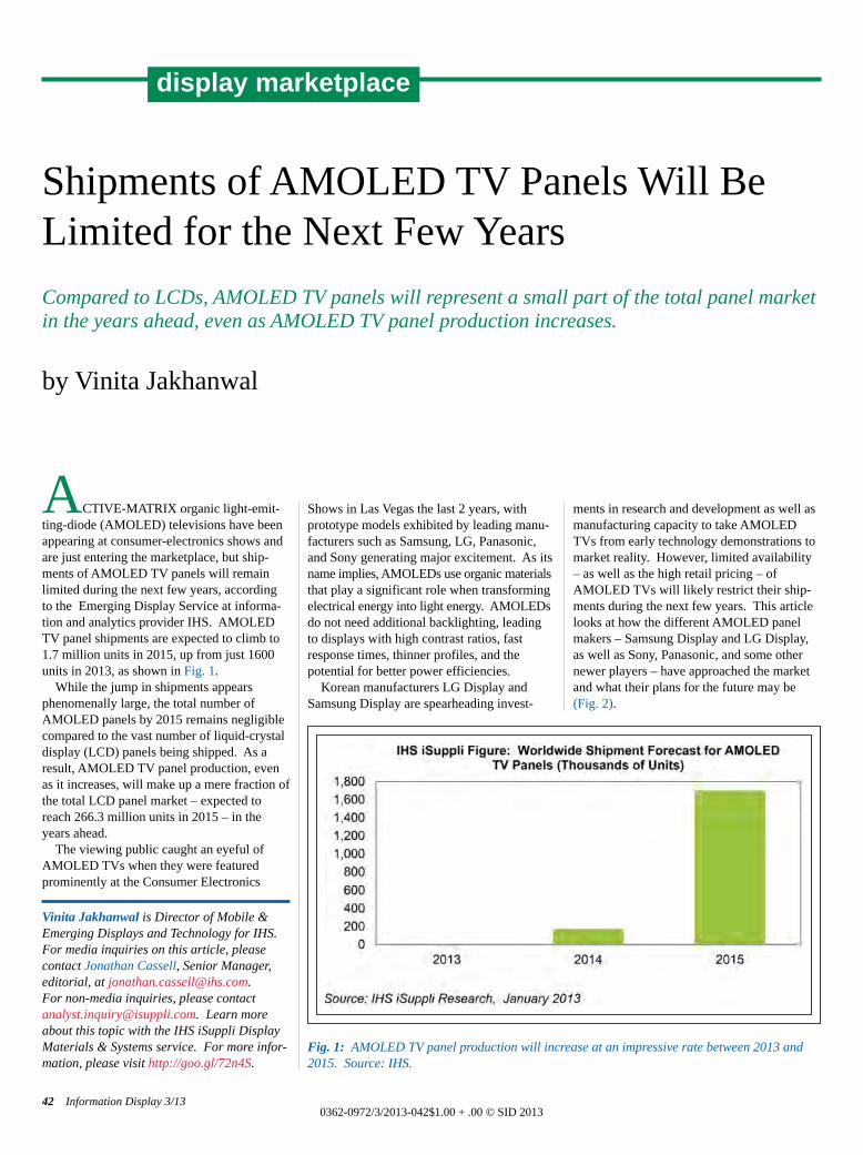
ACTIVE-MATRIX organic light-emit-ting-diode (AMOLED) televisions have beenappearing at consumer-electronics shows andare just entering the marketplace, but ship-ments of AMOLED TV panels will remainlimited during the next few years, accordingto the Emerging Display Service at informa-tion and analytics provider IHS. AMOLEDTV panel shipments are expected to climb to1.7 million units in 2015, up from just 1600units in 2013, as shown in Fig. 1. While the jump in shipments appears
phenomenally large, the total number ofAMOLED panels by 2015 remains negligiblecompared to the vast number of liquid-crystaldisplay (LCD) panels being shipped. As a result, AMOLED TV panel production, evenas it increases, will make up a mere fraction ofthe total LCD panel market – expected toreach 266.3 million units in 2015 – in theyears ahead.The viewing public caught an eyeful of
AMOLED TVs when they were featuredprominently at the Consumer Electronics
Shows in Las Vegas the last 2 years, with prototype models exhibited by leading manu-facturers such as Samsung, LG, Panasonic,and Sony generating major excitement. As itsname implies, AMOLEDs use organic materialsthat play a significant role when transformingelectrical energy into light energy. AMOLEDsdo not need additional backlighting, leading to displays with high contrast ratios, fastresponse times, thinner profiles, and thepotential for better power efficiencies. Korean manufacturers LG Display and
Samsung Display are spearheading invest-
ments in research and development as well asmanufacturing capacity to take AMOLEDTVs from early technology demonstrations tomarket reality. However, limited availability– as well as the high retail pricing – ofAMOLED TVs will likely restrict their ship-ments during the next few years. This articlelooks at how the different AMOLED panelmakers – Samsung Display and LG Display,as well as Sony, Panasonic, and some othernewer players – have approached the marketand what their plans for the future may be(Fig. 2).
Shipments of AMOLED TV Panels Will BeLimited for the Next Few YearsCompared to LCDs, AMOLED TV panels will represent a small part of the total panel marketin the years ahead, even as AMOLED TV panel production increases.
by Vinita Jakhanwal
Vinita Jakhanwal is Director of Mobile &Emerging Displays and Technology for IHS.For media inquiries on this article, pleasecontact Jonathan Cassell, Senior Manager,editorial, at [email protected]. For non-media inquiries, please contact [email protected]. Learn moreabout this topic with the IHS iSuppli DisplayMaterials & Systems service. For more infor-mation, please visit http://goo.gl/72n4S.
42 Information Display 3/130362-0972/3/2013-042$1.00 + .00 © SID 2013
display marketplace
Fig. 1: AMOLED TV panel production will increase at an impressive rate between 2013 and2015. Source: IHS.
Jakhanwal p42-44_Layout 1 4/20/2013 10:42 PM Page 42
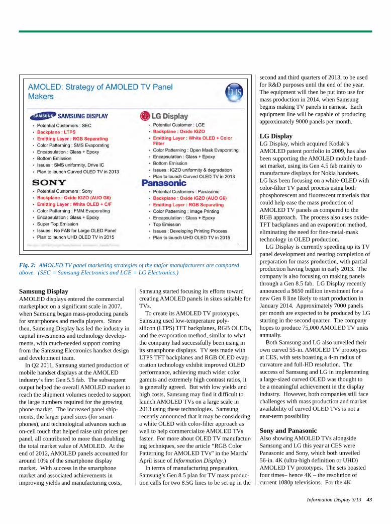
Samsung DisplayAMOLED displays entered the commercialmarketplace on a significant scale in 2007,when Samsung began mass-producing panelsfor smartphones and media players. Sincethen, Samsung Display has led the industry incapital investments and technology develop-ments, with much-needed support comingfrom the Samsung Electronics handset designand development team. In Q2 2011, Samsung started production of
mobile handset displays at the AMOLEDindustry’s first Gen 5.5 fab. The subsequentoutput helped the overall AMOLED market toreach the shipment volumes needed to supportthe large numbers required for the growingphone market. The increased panel ship-ments, the larger panel sizes (for smart-phones), and technological advances such ason-cell touch that helped raise unit prices perpanel, all contributed to more than doublingthe total market value of AMOLED. At theend of 2012, AMOLED panels accounted foraround 10% of the smartphone display market. With success in the smartphone market and associated achievements inimproving yields and manufacturing costs,
Samsung started focusing its efforts towardcreating AMOLED panels in sizes suitable forTVs. To create its AMOLED TV prototypes,
Samsung used low-temperature poly-silicon (LTPS) TFT backplanes, RGB OLEDs,and the evaporation method, similar to whatthe company had successfully been using inits smartphone displays. TV sets made withLTPS TFT backplanes and RGB OLED evap-oration technology exhibit improved OLEDperformance, achieving much wider colorgamuts and extremely high contrast ratios, itis generally agreed. But with low yields andhigh costs, Samsung may find it difficult tolaunch AMOLED TVs on a large scale in2013 using these technologies. Samsungrecently announced that it may be consideringa white OLED with color-filter approach aswell to help commercialize AMOLED TVsfaster. For more about OLED TV manufactur-ing techniques, see the article “RGB ColorPatterning for AMOLED TVs” in the March/April issue of Information Display.) In terms of manufacturing preparation,
Samsung’s Gen 8.5 plan for TV mass produc-tion calls for two 8.5G lines to be set up in the
second and third quarters of 2013, to be usedfor R&D purposes until the end of the year.The equipment will then be put into use formass production in 2014, when Samsungbegins making TV panels in earnest. Eachequipment line will be capable of producingapproximately 9000 panels per month.
LG DisplayLG Display, which acquired Kodak’sAMOLED patent portfolio in 2009, has alsobeen supporting the AMOLED mobile hand-set market, using its Gen 4.5 fab mainly tomanufacture displays for Nokia handsets. LG has been focusing on a white-OLED withcolor-filter TV panel process using both phosphorescent and fluorescent materials thatcould help ease the mass production ofAMOLED TV panels as compared to theRGB approach. The process also uses oxide-TFT backplanes and an evaporation method,eliminating the need for fine-metal-mask technology in OLED production.LG Display is currently speeding up its TV
panel development and nearing completion ofpreparation for mass production, with partialproduction having begun in early 2013. Thecompany is also focusing on making panelsthrough a Gen 8.5 fab. LG Display recentlyannounced a $650 million investment for anew Gen 8 line likely to start production inJanuary 2014. Approximately 7000 panelsper month are expected to be produced by LGstarting in the second quarter. The companyhopes to produce 75,000 AMOLED TV unitsannually. Both Samsung and LG also unveiled their
own curved 55-in. AMOLED TV prototypesat CES, with sets boasting a 4-m radius of curvature and full-HD resolution. The success of Samsung and LG in implementinga large-sized curved OLED was thought to be a meaningful achievement in the displayindustry. However, both companies still facechallenges with mass production and marketavailability of curved OLED TVs is not anear-term possibility
Sony and PanasonicAlso showing AMOLED TVs alongside Samsung and LG this year at CES were Panasonic and Sony, which both unveiled 56-in. 4K (ultra-high definition or UHD)AMOLED TV prototypes. The sets boastedfour times– hence 4K – the resolution of current 1080p televisions. For the 4K
Information Display 3/13 43
Fig. 2: AMOLED TV panel marketing strategies of the major manufacturers are comparedabove. (SEC = Samsung Electronics and LGE = LG Electronics.)
Jakhanwal p42-44_Layout 1 4/20/2013 10:42 PM Page 43
AMOLED samples, both manufacturers usedoxide-TFT backplanes, which should incurlower manufacturing costs than LTPS back-planes at some future time, when processesare perfected.Back in 2007, Sony launched an 11-in.
AMOLED TV based on RGB emitters at CESand then continued to produce this TV insmall volumes for 5 years before discontinu-ing it by 2012 because of high manufacturingcosts and low yields. To make the TV itshowed at CES this year, Sony used evapora-tion technology to deposit organic material inits top-emitting white-OLED structure with acolor filter. Sony’s panel was provided byAUO of Taiwan in joint development effortsbetween the Japanese and Taiwanese partners.Sony’s (top) emission technology optimizesthe OLED structure, which helps achieve better light management, enhances colorpurity, and attains higher contrast at lowerpower-consumption levels. For its 56-in. 4KAMOLED TV at CES, Panasonic used the so-called “printing” method, a technologydesigned to make OLED production adaptablefor a wider range of display sizes. (Thedetails of Panasonic’s “printing” methodremain undisclosed at the moment.) At CES,AUO also introduced its own 32-in. AMOLEDTV using an oxide-TFT backplane with awhite-OLED structure. Using different technological approaches,
Sony and Panasonic were both able to makeUHD 56-in. displays that reached 79 pixelsper inch (ppi) –twice the density of the 55-in.FHD displays used in the OLED TVs fromLG and Samsung. The latters’ TVs are closerto mass production, however. LG and Samsung had positioned themselves to releaselarge-sized AMOLED TVs at an earlier datethan Sony or Panasonic. In Japan, Panasonicand Sony have started joint work to study how to make large-sized AMOLED panels on a commercial basis by using Panasonic’sHimeji fab, but it is not certain if investingcapital is being considered for a productionline. Sony is currently producing 17- and 25-in. AMOLED monitor panels for thebroadcasting industry.
Other Market PlayersWhile the South Koreans appear to have ahead start in AMOLED panel production,panel makers in China, Taiwan, and Japan arealso hoping to enter the market. In China,backed by government support, most Chinese
panel makers are looking at starting their ownAMOLED business. Nonetheless, given thetwin challenges of high costs and low yieldsassociated with commercializing backplaneand deposition processes, large-scale AMOLEDproduction from China is unlikely anytimesoon. Many Chinese panel makers – includ-ing CSOT from Shenzhen, Visionox fromKunshan, Tianma from Shanghai, BOE inHerfei, and CCO from Chengdu – all haveannounced investments and plans for AMOLEDproduction, but none has materialized withimmediate production. For their part, panel makers from Taiwan
are trying to achieve commercial success withas little investment as possible, as financiallythey cannot afford on their own to bring innew production equipment for AMOLED,LTPS, and oxide TFTs. AUO, which hasfacilities in Singapore and Linkou that arefocused on producing small- and medium-sized AMOLED panels, failed to keep up withits plan to produce 4.3-in. AMOLED panels inthe second quarter of 2012 – and thenrescheduled production for the first half ofthis year. AUO’s Lungtan facility will likelybe used for producing AMOLED TV panels,however, with technological support fromSony in developing oxide-TFT backplanes toproduce 32-in. OLED TVs beginning the second half of this year.
Yield Improvement and Cost ReductionRemain BarriersWhile OLED TV makers all hope to becomethe acknowledged leaders in their space, moreimprovements in technology, materials, andmanufacturing appear to be needed in order tobring large numbers of AMOLED TVs to themarket. And, in addition to technical andlarge-volume manufacturing challenges,OLED TVs also face an uphill task of compet-ing on prices with lower-priced, low-power,higher-resolution 4K LCDs and even FHDLCD TVs. By the time AMOLED TV pro-duction achieves efficiencies in large-scaleproduction, LCD TVs will have had an oppor-tunity to become even more competitive inprice and performance. Despite the appear-ance of many promising AMOLED TV proto-types at CES, the number of challenges thatstill need to be addressed mean that most consumers are likely to wait a few more yearsbefore they buy their AMOLED TVs. n
display marketplace
Jakhanwal p42-44_Layout 1 4/20/2013 10:42 PM Page 44
For more information visit: sid.newhavendisplay.com Contact us at: 847-844-8795
NEWHAVEN DISPLAY INTERNATIONAL
A worldwide s� ution for an international need.Multi-Font Graphic OLEDs
Displays multiple languages at one time
Includes 37 font tables
Supports 50+ languages
Fast response time: 10µs
Easy to use, all-in-one designs
New
sid.newhavendisplay.com NEWHAVEN DISPLAY INTERNATIONAL
A worldwide s� ution for an international need.A worldwide s� ution for an international need.A worldwide s� ution for an international need.A worldwide s� ution for an international need.A worldwide s� ution for an international need.Multi-Font Graphic OLEDsA worldwide s� ution for an international need.Displays multiple languages at one time
NEWHAVEN DISPLAY INTERNATIONAL
A worldwide s� ution for an international need.A worldwide s� ution for an international need.
Your Window to the Digital WorldSolomon Goldentek Display (SGD) is a world leader in LCD Manufacturing with factories
in Taiwan and China producing TN, STN, TFT and Capacitive Touch Panel technology.
Your local support for design, engineering & sales:SGD America, Inc. • 851 W. Maple Rd, Clawson, MI 48017 • (248) 288-2288 e-mail: [email protected]
High Quality, Custom & Standard LCD/LCM Modules at Globally Competitive Pricing:• Total solution design • Solomon Group resources • 30+ years in global market • Local sales & distribution support • Flexible product line and ordering policies
Ad p45.indd 1 4/21/2013 3:54:29 PM
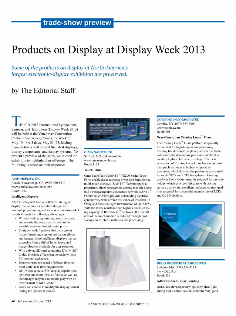
THE SID 2013 International Symposium,Seminar, and Exhibition (Display Week 2013)will be held at the Vancouver ConventionCentre in Vancouver, Canada, the week of May 19. For 3 days, May 21–23, leadingmanufacturers will present the latest displays,display components, and display systems. Topresent a preview of the show, we invited theexhibitors to highlight their offerings. Thefollowing is based on their responses.
AMP DISPLAY, INC.Rancho Cucamonga, CA (909) 980-1310www.amdisplay.com/index.phpBooth 1032
Intelligent Displays
AMP Display will feature a DWIN Intelligent display that allows for interface design with minimal programming and increases time-to-marketspeeds through the following advantages:
• Without code programming, users may readand rewrite the code that is stored in the variable memory through serial ports.
• Equipped with functions that can convertimage format and support animation effectsand images, these intelligent displays has anextensive library full of fonts, icons, andimage libraries available for user selection.
• With only an SD card containing DWIN_SETfolder, interface effects can be made withoutPC terminal assistance.
• Extreme response speed of refresh time tomeet users’ real-time requirements.
• DGUS can achieve RTC display capabilities:up/down and zoom-in/out of curve as well asicon/images recycles automatic play with noinvolvement of MCU code.
• Users can choose to modify the display formatduring the operation process.
CIMA NANOTECHSt. Paul, MN 651/646-6266www.cimananotech.comBooth 1131
Touch Films
Cima NanoTech’s SANTE™ FS200 Series Touch Films enable faster-response lower-cost large-format multi-touch displays. SANTE™ Technology is a proprietary silver nanoparticle coating that self-aligns into a transparent ultra-conductive network. SANTE™
FS200 Touch Films provide outstanding electricalconductivity with surface resistance of less than 25W/sq. and excellent light transmission of up to 88%.With the lower resistance and higher current-carry-ing capacity of the SANTE™ Network, the overallcost of the touch module is reduced through costsavings on IC chips, materials and processing.
CORNING INCORPORATEDCorning, NY (607) 974-9000www.corning.comBooth 801
Next-Generation Corning Lotus™ Glass
The Corning Lotus™ Glass platform is specially formulated for high-temperature processing. Corning has developed a glass platform that betterwithstands the demanding processes involved increating high-performance displays. The next generation of Corning Lotus Glass has exceptionaltotal pitch variation in higher-temperature processes, which delivers the performance requiredfor oxide TFTs and LTPS backplanes. Corning produces Lotus Glass using its patented fusion tech-nology, which provides flat glass with pristine surface quality and excellent thickness control qual-ities essential for successful manufacture of LCDsand OLED displays.
DELO INDUSTRIAL ADHESIVESSudbury, MA (978) 254-5275www.DELO.usBooth 539
Adhesives for Display Bonding
DELO has developed new optically clear light-curing liquid adhesives that combine very good
Products on Display at Display Week 2013Some of the products on display at North America’s largest electronic-display exhibition are previewed.
by The Editorial Staff
46 Information Display 3/130362-0972/3/2013-046$1.00 + .00 © SID 2013
trade-show preview
Products on Display p46-55_Layout 1 4/20/2013 11:13 PM Page 46
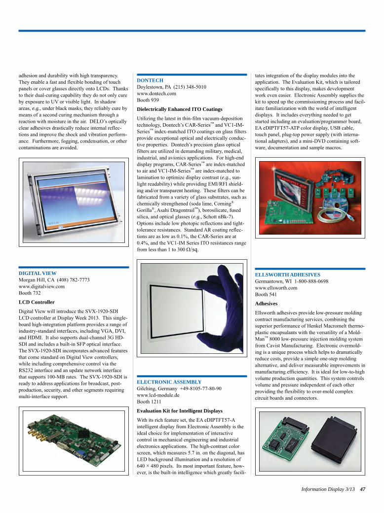
adhesion and durability with high transparency.They enable a fast and flexible bonding of touchpanels or cover glasses directly onto LCDs. Thanksto their dual-curing capability they do not only cureby exposure to UV or visible light. In shadowareas, e.g., under black masks, they reliably cure bymeans of a second curing mechanism through areaction with moisture in the air. DELO’s opticallyclear adhesives drastically reduce internal reflec-tions and improve the shock and vibration perform-ance. Furthermore, fogging, condensation, or othercontaminations are avoided.
DIGITAL VIEWMorgan Hill, CA (408) 782-7773www.digitalview.comBooth 732
LCD Controller
Digital View will introduce the SVX-1920-SDILCD controller at Display Week 2013. This single-board high-integration platform provides a range ofindustry-standard interfaces, including VGA, DVI,and HDMI. It also supports dual-channel 3G HD-SDI and includes a built-in SFP optical interface.The SVX-1920-SDI incorporates advanced featuresthat come standard on Digital View controllers,while including comprehensive control via theRS232 interface and an update network interfacethat supports 100-MB rates. The SVX-1920-SDI isready to address applications for broadcast, post-production, security, and other segments requiringmulti-interface support.
DONTECHDoylestown, PA (215) 348-5010www.dontech.comBooth 939
Dielectrically Enhanced ITO Coatings
Utilizing the latest in thin-film vacuum-depositiontechnology, Dontech’s CAR-Series™ and VC1-IM-Series™ index-matched ITO coatings on glass filtersprovide exceptional optical and electrically conduc-tive properties. Dontech’s precision glass opticalfilters are utilized in demanding military, medical,industrial, and avionics applications. For high-enddisplay programs, CAR-Series™ are index-matchedto air and VC1-IM-Series™ are index-matched tolamination to optimize display contrast (e.g., sun-light readability) while providing EMI/RFI shield-ing and/or transparent heating. These filters can befabricated from a variety of glass substrates, such aschemically strengthened (soda lime, Corning®
Gorilla®, Asahi Dragontrail™), borosilicate, fusedsilica, and optical glasses (e.g., Schott nBk-7).Options include low photopic reflections and tight-tolerance resistances. Standard AR coating reflec-tions are as low as 0.1%, the CAR-Series are at0.4%, and the VC1-IM Series ITO resistances rangefrom less than 1 to 300 W/sq.
ELECTRONIC ASSEMBLYGilching, Germany +49-8105-77-80-90www.lcd-module.deBooth 1211
Evaluation Kit for Intelligent Displays
With its rich feature set, the EA eDIPTFT57-Aintelligent display from Electronic Assembly is theideal choice for implementation of interactive control in mechanical engineering and industrialelectronics applications. The high-contrast colorscreen, which measures 5.7 in. on the diagonal, hasLED background illumination and a resolution of640 × 480 pixels. Its most important feature, how-ever, is the built-in intelligence which greatly facili-
tates integration of the display modules into theapplication. The Evaluation Kit, which is tailoredspecifically to this display, makes developmentwork even easier. Electronic Assembly supplies thekit to speed up the commissioning process and facil-itate familiarization with the world of intelligentdisplays. It includes everything needed to getstarted including an evaluation/programmer board,EA eDIPTFT57-ATP color display, USB cable,touch panel, plug-top power supply (with interna-tional adapters), and a mini-DVD containing soft-ware, documentation and sample macros.
ELLSWORTH ADHESIVESGermantown, WI 1-800-888-0698www.ellsworth.comBooth 541
Adhesives
Ellsworth adhesives provide low-pressure moldingcontract manufacturing services, combining thesuperior performance of Henkel Macromelt thermo-plastic encapsulants with the versatility of a Mold-Man™ 8000 low-pressure injection molding systemfrom Cavist Manufacturing. Electronic overmold-ing is a unique process which helps to dramaticallyreduce costs, provide a simple one-step moldingalternative, and deliver measurable improvements inmanufacturing efficiency. It is ideal for low-to-highvolume production quantities. This system controlsvolume and pressure independent of each other providing the flexibility to over-mold complex circuit boards and connectors.
Information Display 3/13 47
Products on Display p46-55_Layout 1 4/20/2013 11:13 PM Page 47
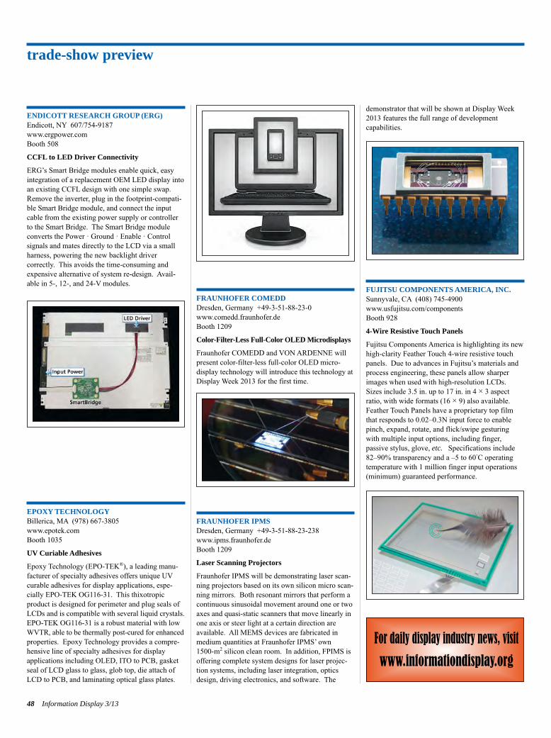
ENDICOTT RESEARCH GROUP (ERG)Endicott, NY 607/754-9187www.ergpower.comBooth 508
CCFL to LED Driver Connectivity
ERG’s Smart Bridge modules enable quick, easyintegration of a replacement OEM LED display intoan existing CCFL design with one simple swap.Remove the inverter, plug in the footprint-compati-ble Smart Bridge module, and connect the inputcable from the existing power supply or controllerto the Smart Bridge. The Smart Bridge moduleconverts the Power · Ground · Enable · Control signals and mates directly to the LCD via a smallharness, powering the new backlight driver correctly. This avoids the time-consuming andexpensive alternative of system re-design. Avail-able in 5-, 12-, and 24-V modules.
EPOXY TECHNOLOGYBillerica, MA (978) 667-3805www.epotek.comBooth 1035
UV Curiable Adhesives
Epoxy Technology (EPO-TEK®), a leading manu-facturer of specialty adhesives offers unique UVcurable adhesives for display applications, espe-cially EPO-TEK OG116-31. This thixotropic product is designed for perimeter and plug seals ofLCDs and is compatible with several liquid crystals.EPO-TEK OG116-31 is a robust material with low WVTR, able to be thermally post-cured for enhanced properties. Epoxy Technology provides a compre-hensive line of specialty adhesives for display applications including OLED, ITO to PCB, gasketseal of LCD glass to glass, glob top, die attach ofLCD to PCB, and laminating optical glass plates.
FRAUNHOFER COMEDDDresden, Germany +49-3-51-88-23-0www.comedd.fraunhofer.deBooth 1209
Color-Filter-Less Full-Color OLED Microdisplays
Fraunhofer COMEDD and VON ARDENNE willpresent color-filter-less full-color OLED micro-display technology will introduce this technology atDisplay Week 2013 for the first time.
FRAUNHOFER IPMSDresden, Germany +49-3-51-88-23-238www.ipms.fraunhofer.deBooth 1209
Laser Scanning Projectors
Fraunhofer IPMS will be demonstrating laser scan-ning projectors based on its own silicon micro scan-ning mirrors. Both resonant mirrors that perform acontinuous sinusoidal movement around one or twoaxes and quasi-static scanners that move linearly inone axis or steer light at a certain direction areavailable. All MEMS devices are fabricated inmedium quantities at Fraunhofer IPMS’ own 1500-m2 silicon clean room. In addition, FPIMS isoffering complete system designs for laser projec-tion systems, including laser integration, opticsdesign, driving electronics, and software. The
demonstrator that will be shown at Display Week2013 features the full range of development capabilities.
FUJITSU COMPONENTS AMERICA, INC.Sunnyvale, CA (408) 745-4900www.usfujitsu.com/componentsBooth 928
4-Wire Resistive Touch Panels
Fujitsu Components America is highlighting its newhigh-clarity Feather Touch 4-wire resistive touchpanels. Due to advances in Fujitsu’s materials andprocess engineering, these panels allow sharperimages when used with high-resolution LCDs.Sizes include 3.5 in. up to 17 in. in 4 × 3 aspectratio, with wide formats (16 × 9) also available.Feather Touch Panels have a proprietary top filmthat responds to 0.02–0.3N input force to enablepinch, expand, rotate, and flick/swipe gesturingwith multiple input options, including finger, passive stylus, glove, etc. Specifications include82–90% transparency and a –5 to 60°C operatingtemperature with 1 million finger input operations(minimum) guaranteed performance.
trade-show preview
48 Information Display 3/13
For daily display industry news, visit
www.informationdisplay.org
Products on Display p46-55_Layout 1 4/20/2013 11:13 PM Page 48
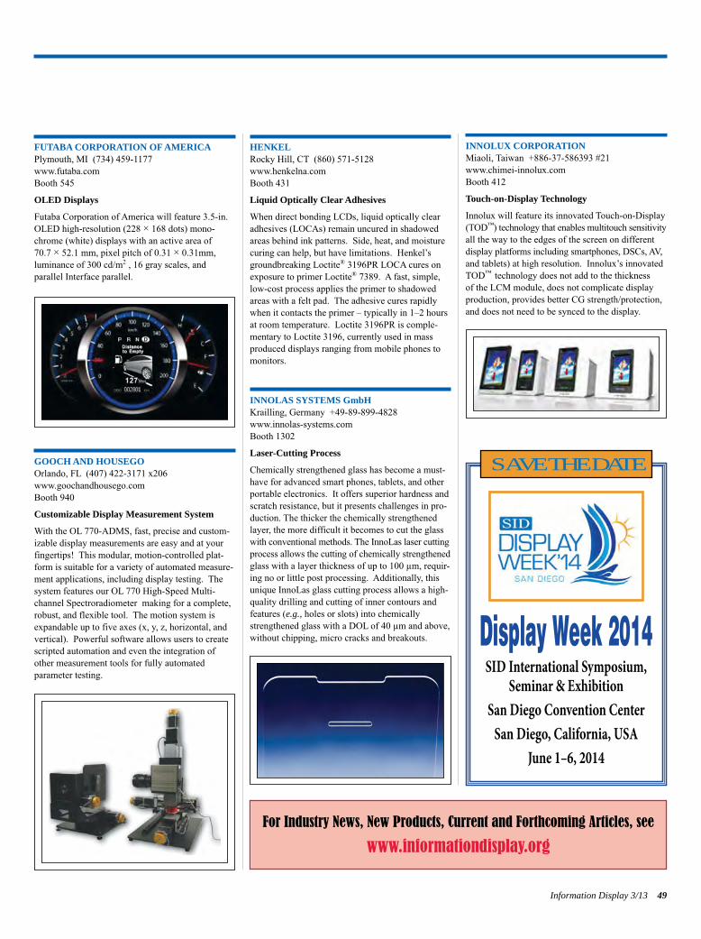
FUTABA CORPORATION OF AMERICAPlymouth, MI (734) 459-1177www.futaba.comBooth 545
OLED Displays
Futaba Corporation of America will feature 3.5-in.OLED high-resolution (228 × 168 dots) mono-chrome (white) displays with an active area of 70.7 × 52.1 mm, pixel pitch of 0.31 × 0.31mm,luminance of 300 cd/m2 , 16 gray scales, and parallel Interface parallel.
GOOCH AND HOUSEGOOrlando, FL (407) 422-3171 x206www.goochandhousego.comBooth 940
Customizable Display Measurement System
With the OL 770-ADMS, fast, precise and custom-izable display measurements are easy and at yourfingertips! This modular, motion-controlled plat-form is suitable for a variety of automated measure-ment applications, including display testing. Thesystem features our OL 770 High-Speed Multi-channel Spectroradiometer making for a complete,robust, and flexible tool. The motion system isexpandable up to five axes (x, y, z, horizontal, andvertical). Powerful software allows users to createscripted automation and even the integration ofother measurement tools for fully automated parameter testing.
HENKELRocky Hill, CT (860) 571-5128www.henkelna.comBooth 431
Liquid Optically Clear Adhesives
When direct bonding LCDs, liquid optically clearadhesives (LOCAs) remain uncured in shadowedareas behind ink patterns. Side, heat, and moisturecuring can help, but have limitations. Henkel’sgroundbreaking Loctite® 3196PR LOCA cures onexposure to primer Loctite® 7389. A fast, simple,low-cost process applies the primer to shadowedareas with a felt pad. The adhesive cures rapidlywhen it contacts the primer – typically in 1–2 hoursat room temperature. Loctite 3196PR is comple-mentary to Loctite 3196, currently used in massproduced displays ranging from mobile phones tomonitors.
INNOLAS SYSTEMS GmbHKrailling, Germany +49-89-899-4828www.innolas-systems.comBooth 1302
Laser-Cutting Process
Chemically strengthened glass has become a must-have for advanced smart phones, tablets, and otherportable electronics. It offers superior hardness andscratch resistance, but it presents challenges in pro-duction. The thicker the chemically strengthenedlayer, the more difficult it becomes to cut the glass with conventional methods. The InnoLas laser cutting process allows the cutting of chemically strengthened glass with a layer thickness of up to 100 µm, requir-ing no or little post processing. Additionally, thisunique InnoLas glass cutting process allows a high-quality drilling and cutting of inner contours andfeatures (e.g., holes or slots) into chemicallystrengthened glass with a DOL of 40 µm and above,without chipping, micro cracks and breakouts.
INNOLUX CORPORATIONMiaoli, Taiwan +886-37-586393 #21www.chimei-innolux.comBooth 412
Touch-on-Display Technology
Innolux will feature its innovated Touch-on-Display (TOD™) technology that enables multitouch sensitivity all the way to the edges of the screen on different display platforms including smartphones, DSCs, AV, and tablets) at high resolution. Innolux’s innovatedTOD™ technology does not add to the thickness of the LCM module, does not complicate display production, provides better CG strength/protection,and does not need to be synced to the display.
Information Display 3/13 49
Display Week 2014SID International Symposium,
Seminar & ExhibitionSan Diego Convention CenterSan Diego, California, USA
June 1–6, 2014
SAVE THE DATE
For Industry News, New Products, Current and Forthcoming Articles, see
www.informationdisplay.org
Products on Display p46-55_Layout 1 4/20/2013 11:13 PM Page 49
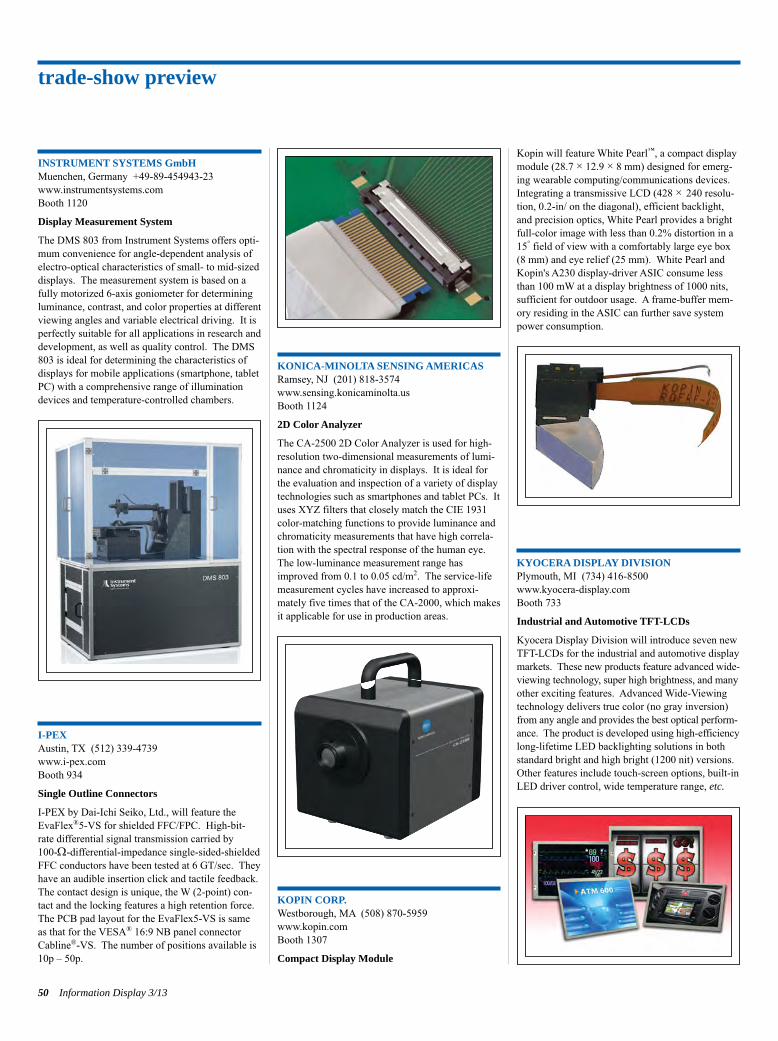
INSTRUMENT SYSTEMS GmbHMuenchen, Germany +49-89-454943-23www.instrumentsystems.comBooth 1120
Display Measurement System
The DMS 803 from Instrument Systems offers opti-mum convenience for angle-dependent analysis ofelectro-optical characteristics of small- to mid-sizeddisplays. The measurement system is based on afully motorized 6-axis goniometer for determiningluminance, contrast, and color properties at differentviewing angles and variable electrical driving. It isperfectly suitable for all applications in research anddevelopment, as well as quality control. The DMS803 is ideal for determining the characteristics ofdisplays for mobile applications (smartphone, tabletPC) with a comprehensive range of illuminationdevices and temperature-controlled chambers.
I-PEXAustin, TX (512) 339-4739www.i-pex.comBooth 934
Single Outline Connectors
I-PEX by Dai-Ichi Seiko, Ltd., will feature theEvaFlex®5-VS for shielded FFC/FPC. High-bit-rate differential signal transmission carried by 100-W-differential-impedance single-sided-shieldedFFC conductors have been tested at 6 GT/sec. Theyhave an audible insertion click and tactile feedback.The contact design is unique, the W (2-point) con-tact and the locking features a high retention force.The PCB pad layout for the EvaFlex5-VS is sameas that for the VESA® 16:9 NB panel connectorCabline®-VS. The number of positions available is10p – 50p.
KONICA-MINOLTA SENSING AMERICASRamsey, NJ (201) 818-3574www.sensing.konicaminolta.usBooth 1124
2D Color Analyzer
The CA-2500 2D Color Analyzer is used for high-resolution two-dimensional measurements of lumi-nance and chromaticity in displays. It is ideal forthe evaluation and inspection of a variety of displaytechnologies such as smartphones and tablet PCs. Ituses XYZ filters that closely match the CIE 1931color-matching functions to provide luminance andchromaticity measurements that have high correla-tion with the spectral response of the human eye.The low-luminance measurement range hasimproved from 0.1 to 0.05 cd/m2. The service-lifemeasurement cycles have increased to approxi-mately five times that of the CA-2000, which makesit applicable for use in production areas.
KOPIN CORP.Westborough, MA (508) 870-5959www.kopin.comBooth 1307
Compact Display Module
Kopin will feature White Pearl™, a compact displaymodule (28.7 × 12.9 × 8 mm) designed for emerg-ing wearable computing/communications devices.Integrating a transmissive LCD (428 × 240 resolu-tion, 0.2-in/ on the diagonal), efficient backlight,and precision optics, White Pearl provides a brightfull-color image with less than 0.2% distortion in a15° field of view with a comfortably large eye box (8 mm) and eye relief (25 mm). White Pearl andKopin's A230 display-driver ASIC consume lessthan 100 mW at a display brightness of 1000 nits,sufficient for outdoor usage. A frame-buffer mem-ory residing in the ASIC can further save systempower consumption.
KYOCERA DISPLAY DIVISIONPlymouth, MI (734) 416-8500www.kyocera-display.comBooth 733
Industrial and Automotive TFT-LCDs
Kyocera Display Division will introduce seven newTFT-LCDs for the industrial and automotive display markets. These new products feature advanced wide-viewing technology, super high brightness, and many other exciting features. Advanced Wide-Viewingtechnology delivers true color (no gray inversion) from any angle and provides the best optical perform-ance. The product is developed using high-efficiency long-lifetime LED backlighting solutions in bothstandard bright and high bright (1200 nit) versions.Other features include touch-screen options, built-inLED driver control, wide temperature range, etc.
trade-show preview
50 Information Display 3/13
Products on Display p46-55_Layout 1 4/20/2013 11:13 PM Page 50
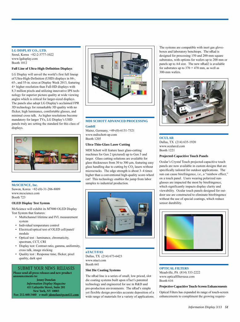
LG DISPLAY CO., LTD.Seoul, Korea +82-2-3777-1022www.lgdisplay.comBooth 1012
Full Line of Ultra-High-Definition Displays
LG Display will unveil the world’s first full lineupof Ultra-High-Definition (UHD) displays in 84-, 65-, and 55-in. sizes at Display Week 2013, featuring4× higher resolution than Full-HD displays with 8.3 million pixels and utilizing innovative IPS tech-nology for superior picture quality at wide viewingangles which is critical for larger-sized displays.The panels also adopt LG Display's acclaimed FPR3D technology for remarkable 3D quality with noflicker, high luminance, comfortable glasses, andminimal cross talk. As higher resolutions becomemandatory for larger TVs, LG Display’s UHD panels truly are setting the standard for this class ofdisplays.
McSCIENCE, Inc.Suwon, Korea +82-(0)-31-206-8009www.mcscience.comBooth 723
OLED Display Test System
McScience will exhibit its M7000 OLED DisplayTest System that features:
• Multichannel lifetime and IVL measurementsystem
• Individual temperature control• Electrical/optical test of OLED cell/panel/
module • Optical test : luminance, chromaticity,
spectrum, CCT, CRI• Display test: Contrast ratio, gamma, uniformity,
cross talk, image sticking• Quality test : Response time, flicker, pixel
quality, dark spot
MDI SCHOTT ADVANCED PROCESSINGGmbHMainz, Germany, +49-(0)-6131-7321www.mdischott-ap.comBooth 1205
Ultra-Thin-Glass Laser Cutting
MDI Schott will feature laser glass-cuttingmachines for Gen 2 (pictured) up to Gen 5 andlarger. Glass cutting solutions are available forglass thicknesses from 30 to 300 µm, featuring easyglass handling due to cutting by CO2 lasers withoutmicrocracks. The edge strength is about 3–4 timeshigher than a conventional high-quality score-wheelcut! This technology enables the jump from laborsamples to industrial production.
nTACT/FASDallas, TX (214) 673-6423www.ntact.comBooth 641
Slot Die Coating Systems
The nRad line is a series of small, low priced, slotdie coating systems built upon nTact’s patentedtechnology and engineered for use in R&D and pre-production environments. The nRad’s simpleyet flexible design provides accurate deposition of awide range of materials for a variety of applications.
The systems are compatible with inert gas glove-boxes and laboratory benchtops. The nRad isdesigned for processing 150 and 200-mm squaresubstrates, with options for wafers up to 200 mm orpanels up to A4 size. The new nRad2 is availablefor substrates up to 370 × 470 mm, as well as 300-mm wafers.
OCULARDallas, TX (214) 635-1920www.ocularcd.comBooth 1221
Projected-Capacitive Touch Panels
Ocular’s Crystal Touch projected-capacitive touchpanels are now available in custom designs that arespecifically tailored for outdoor applications. Thesun can cause birefringence, i.e., a “rainbow effect,”on a touch panel. Users wearing polarized sun-glasses are impacted the most by birefringence,which significantly impacts display clarity andviewability. Ocular touch panels designed for out-door use are constructed to eliminate birefringencewithout the use of special coatings, which reducesensor durability.
OPTICAL FILTERSMeadville, PA (814) 333-2222www.opticalfiltersusa.comBooth 616
Projective-Capacitive Touch-Screen Enhancements
Optical Filters has expanded its range of touch-screen enhancements to compliment the growing require-
Information Display 3/13 51
S U B M I T Y O U R N E W S R E L E A S E SPlease send all press releases and new productannouncements to:
Jenny DonelanInformation Display Magazine411 Lafayette Street, Suite 201
New York, NY 10003Fax: 212.460.5460 e-mail: [email protected]
Products on Display p46-55_Layout 1 4/20/2013 11:14 PM Page 51
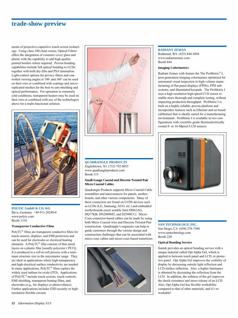
ments of projective-capacitive touch-screen technol-ogy. Using class-100 clean rooms, Optical Filtersoffers the integration of cosmetic cover glass andplastic with the capability to add high-qualityprinted borders where required. Proven bondingcapabilities include full optical bonding to LCDstogether with both dry-film and PSA lamination.Light-control options for privacy filters and con-trolled viewing angles at 180° and 360° can be usedon their own or combined with coatings and micro-replicated meshes for the best in emi-shielding andoptical performance. For operation in extremelycold conditions, transparent heaters may be used ontheir own or combined with any of the technologiesabove for a multi-functional solution.
POLYIC GmbH & CO. KGBava, Germany +49-911-20249-0www.polyic.comBooth 1310
Transparent Conductive Films
PolyTC® films are transparent conductive films fortouch sensors, displays, and EMI protection and can be used for electrodes or electrical heating elements. A PolyTC® film consists of thin metallayers on a plastic film [usually polyester ( PET)].It is produced in a roll-to-roll process with a mini-mum structure size in the micrometer range. Theyare ideal in applications where high transparencyand high electrical surface conductivity are needed.In many applications, PolyTC® films replace thewidely used indium tin oxide (ITO). Applicationsof PolyTC® include touch screens, touch controls,EMI shielding, transparent heating films, and electrodes (e.g., for displays or photovoltaics). Further applications includes ESD security or high-resolution flexible circuits.
QUADRANGLE PRODUCTSEnglishtown, NJ (732) 792-8035www.quadrangleproducts.comBooth 313
Small-Gauge Coaxial and Discrete Twisted-PairMicro Coaxial Cables
Quadrangle Products supports Micro Coaxial Cableassemblies and interconnects for panels, mother-boards, and other various components. Many ofthese connectors are found on LVDS devices suchas LCDs (LG, Samsung, AUO, etc.) and embeddedmotherboards (most notably Intel DH61AG,DQ77KB, DN2800MT, and D2500CC). Micro-Coax-connector-based cables can be made by usingboth Micro Coaxial wire and Discrete Twisted-Pairconstruction. Quadrangle’s engineers can help toguide customers through the various design andconstruction challenges that can be associated withmicro coax cables and micro-coax-based transitions.
RADIANT ZEMAXRedmond, WA (425) 844-5894www.radiantzemax.comBooth 844
Imaging Colorimeters
Radiant Zemax with feature the The ProMetric® I, next-generation imaging colorimeters optimized forautomated visual inspection in high-volume manu-facturing of flat-panel displays (FPDs), FPD sub-systems, and illuminated keypads. The ProMetric Iuses a high-resolution high-speed CCD sensor toenable more thorough and complete testing, withoutimpacting production throughput. ProMetric I isbuilt on a highly reliable, proven platform andincorporates features such as Ethernet and on-boardcalibration that is ideally suited for a manufacturingenvironment. ProMetric I is available in two con-figurations with scientific-grade thermoelectricallycooled 8- or 16-Mpixel CCD sensors.
SAN TECHNOLOGY, INC.San Diego, CA (858) 278-7300www.santechnology.comBooth 220
Optical Bonding Service
Santek provides an optical bonding service with aunique material called Opt Alpha Gel, which isapplied in between touch panel and LCD, or protec-tive panel. Opt Alpha Gel improves the visibility ofdisplay by decreasing outside light reflection andLCD surface reflection. Also, a higher luminance is obtained by decreasing the reflection from theLCD. In addition, the softness of the gel improvesthe shock resistance and stress release of an LCD.Also, Opt Alpha Gel has flexible workability compared to that of other materials, and it’s re-workable!
trade-show preview
52 Information Display 3/13
Products on Display p46-55_Layout 1 4/20/2013 11:14 PM Page 52
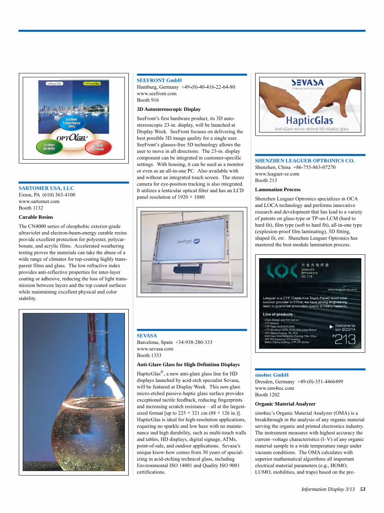
SARTOMER USA, LLCExton, PA (610) 363-4100www.sartomer.comBooth 1132
Curable Resins
The CN4000 series of oleophobic exterior-gradeultraviolet and electron-beam-energy curable resinsprovide excellent protection for polyester, polycar-bonate, and acrylic films. Accelerated weatheringtesting proves the materials can take the abuse of awide range of climates for top-coating highly trans-parent films and glass. The low refractive indexprovides anti-reflective properties for inter-layercoating or adhesive, reducing the loss of light trans-mission between layers and the top coated surfaceswhile maintaining excellent physical and color stability.
SEEFRONT GmbHHamburg, Germany +49-(0)-40-416-22-64-80www.seefront.comBooth 916
3D Autostereoscopic Display
SeeFront’s first hardware product, its 3D auto-stereoscopic 23-in. display, will be launched at Display Week. SeeFront focuses on delivering thebest possible 3D image quality for a single user.SeeFront’s glasses-free 3D technology allows theuser to move in all directions. The 23-in. displaycomponent can be integrated in customer-specificsettings. With housing, it can be used as a monitoror even as an all-in-one PC. Also available withand without an integrated touch screen. The stereocamera for eye-position tracking is also integrated.It utilizes a lenticular optical filter and has an LCDpanel resolution of 1920 × 1080.
SEVASABarcelona, Spain +34-938-280-333www.sevasa.comBooth 1333
Anti-Glare Glass for High-Definition Displays
HapticGlas®, a new anti-glare glass line for HD displays launched by acid-etch specialist Sevasa,will be featured at Display Week. This non-glaremicro-etched passive-haptic glass surface providesexceptional tactile feedback, reducing fingerprintsand increasing scratch resistance – all at the largest-sized format [up to 225 × 321 cm (88 × 126 in.)].HapticGlas is ideal for high-resolution applications,requiring no sparkle and low haze with no mainte-nance and high durability, such as multi-touch wallsand tables, HD displays, digital signage, ATMs,point-of-sale, and outdoor applications. Sevasa’sunique know-how comes from 30 years of special-izing in acid-etching technical glass, includingEnvironmental ISO 14001 and Quality ISO 9001certifications.
SHENZHEN LEAGUER OPTRONICS CO.Shenzhen, China +86-755-863-07270www.leaguer-sz.comBooth 213
Lamonation Process
Shenzhen Leaguer Optronics specializes in OCAand LOCA technology and performs innovativeresearch and development that has lead to a varietyof patents on glass-type or TP-on-LCM (hard tohard fit), film type (soft to hard fit), all-in-one type(explosion-proof film laminating), 3D fitting,shaped fit, etc. Shenzhen Leaguer Optronics hasmastered the best module lamination process.
sim4tec GmbHDresden, Germany +49-(0)-351-4466499www.sim4tec.comBooth 1202
Organic Material Analyzer
sim4tec’s Organic Material Analyzer (OMA) is abreakthrough in the analysis of any organic materialserving the organic and printed electronics industry.The instrument measures with highest accuracy thecurrent–voltage characteristics (I–V) of any organicmaterial sample in a wide temperature range undervacuum conditions. The OMA calculates withsuperior mathematical algorithms all importantelectrical material parameters (e.g., HOMO,LUMO, mobilities, and traps) based on the pre-
Information Display 3/13 53
Products on Display p46-55_Layout 1 4/20/2013 11:14 PM Page 53
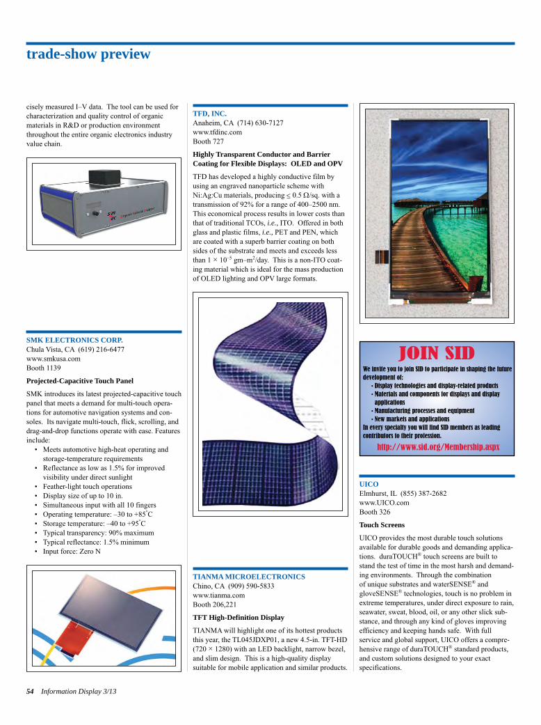
cisely measured I–V data. The tool can be used forcharacterization and quality control of organicmaterials in R&D or production environmentthroughout the entire organic electronics industryvalue chain.
SMK ELECTRONICS CORP.Chula Vista, CA (619) 216-6477www.smkusa.comBooth 1139
Projected-Capacitive Touch Panel
SMK introduces its latest projected-capacitive touchpanel that meets a demand for multi-touch opera-tions for automotive navigation systems and con-soles. Its navigate multi-touch, flick, scrolling, anddrag-and-drop functions operate with ease. Featuresinclude:
• Meets automotive high-heat operating andstorage-temperature requirements
• Reflectance as low as 1.5% for improved visibility under direct sunlight
• Feather-light touch operations• Display size of up to 10 in.• Simultaneous input with all 10 fingers• Operating temperature: –30 to +85°C• Storage temperature: –40 to +95°C• Typical transparency: 90% maximum• Typical reflectance: 1.5% minimum• Input force: Zero N
TFD, INC.Anaheim, CA (714) 630-7127www.tfdinc.comBooth 727
Highly Transparent Conductor and BarrierCoating for Flexible Displays: OLED and OPV
TFD has developed a highly conductive film byusing an engraved nanoparticle scheme withNi:Ag:Cu materials, producing < 0.5 W/sq. with atransmission of 92% for a range of 400–2500 nm.This economical process results in lower costs thanthat of traditional TCOs, i.e., ITO. Offered in bothglass and plastic films, i.e., PET and PEN, whichare coated with a superb barrier coating on bothsides of the substrate and meets and exceeds lessthan 1 × 10⁻⁵ gm–m2/day. This is a non-ITO coat-ing material which is ideal for the mass productionof OLED lighting and OPV large formats.
TIANMA MICROELECTRONICSChino, CA (909) 590-5833www.tianma.comBooth 206,221
TFT High-Definition Display
TIANMA will highlight one of its hottest productsthis year, the TL045JDXP01, a new 4.5-in. TFT-HD(720 × 1280) with an LED backlight, narrow bezel,and slim design. This is a high-quality display suitable for mobile application and similar products.
UICOElmhurst, IL (855) 387-2682www.UICO.comBooth 326
Touch Screens
UICO provides the most durable touch solutionsavailable for durable goods and demanding applica-tions. duraTOUCH® touch screens are built tostand the test of time in the most harsh and demand-ing environments. Through the combination of unique substrates and waterSENSE® andgloveSENSE® technologies, touch is no problem inextreme temperatures, under direct exposure to rain,seawater, sweat, blood, oil, or any other slick sub-stance, and through any kind of gloves improvingefficiency and keeping hands safe. With full service and global support, UICO offers a compre-hensive range of duraTOUCH® standard products,and custom solutions designed to your exact specifications.
trade-show preview
54 Information Display 3/13
JOIN SIDWe invite you to join SID to participate in shaping the futuredevelopment of:
• Display technologies and display-related products• Materials and components for displays and display applications
• Manufacturing processes and equipment• New markets and applications
In every specialty you will find SID members as leading contributors to their profession.
http://www.sid.org/Membership.aspx
Products on Display p46-55_Layout 1 4/20/2013 11:14 PM Page 54
UNIVERSAL DISPLAY CORP.Ewing, NJ 609/671-0980 www.universaldisplay.com Booth 210,514OLED Technologies and Phosphorescent OLEDMaterials
Universal Display, a leading developer of OLED technologies and materials for displays and lighting,will exhibit the company’s product line of energy-efficient UniversalPHOLED® phosphorescent OLED materials, UniversalP2OLED® ink systems for solution processing and prototypes showcasing other proprietary technologies, including its WOLED®
White OLED, flexible OLED, barrier, and advancedpatterning process technologies. Also, offeringtechnology development and technology transfer services to support the smooth adoption of technology and materials.
WESTAR DISPLAY TECHNOLOGIESSt. Charles, MO (636) 300-5100www.westardisplaytechnologies.comBooth 409
Reflective Display Measurement System
The FPM-505R is perfectly suited for automatedreflective measurement and optical performanceassessment of reflective, emissive, and transmissivedisplays under a variety of lighting conditions. TheFPM-505R comes standard with a spectrometer forcenter-screen and viewing-angle measurements ofluminance, color, contrast, uniformity, gamma,color gamut, cross talk, and other custom tests withan optional TRD-200 for temporal measurementssuch as flicker and response time. The FPM-505Rincludes a removable hemisphere which providesillumination for diffuse reflection measurementswhile a directed light source is integrated on a sixthmotorized axis for both specular and diffuse reflec-tion measurements. n
Display Week 2014SID International Symposium,
Seminar & ExhibitionSan Diego Convention CenterSan Diego, California, USA
June 1–6, 2014
SAVE THE DATE
Products on Display p46-55_Layout 1 4/20/2013 11:14 PM Page 55
Winning JSID OutstandingStudent Paper DescribesSolution-Processed Metal Oxide on Flexible Foil
by Jan Genoe and Jenny Donelan
The current flat-panel active-matrix organiclight-emitting-diode (AMOLED) display market is dominated by low-temperature poly-silicon (LTPS) backplane technology on rigidglass plates. LTPS as a backplane for largerdisplay sizes, such as TVs, has some draw-backs. The excimer laser used for LTPS doesnot scale to larger sizes. LTPS is fairly costlyto implement and also requires relatively highprocessing temperatures (>300°C). Thesetemperatures limit the integration of LTPSdirectly onto desirable, lighter weight sub-strates such as flexible foil or plastic, whichdegrade in high heat.In order to create a backplane technology
that could accommodate fabrication on flexiblefoil at a low post-annealing temperature, amultidisciplinary, cross-organizational studentresearch team from Europe demonstrated theuse of high-performance solution-based n-type metal-oxide thin-film-transistors (TFTs). These were fabricated directly on polyimidefoil at a post-annealing temperature of only250°C. This work, as detailed in the paper,“Solution-processed and low-temperaturemetal oxide n-channel thin-film transistorsand low-voltage complementary circuitry onlarge-area flexible polyimide foil,” appearedin the October 2012 issue of the Journal of theSID, earning its authors the award for theJSID Outstanding Student Paper of 2012. The team consisted of Maarten Rockelé,
Duy-Yu Pham, Jürgen Steiger, Silviu Botnaras, Dennis Weber, Jan Vanfleteren, Tom Sterken, Dieter Cuypers, Soeren Steudel, Kris Myny, Sarah Schols, Bas van der Putten, Jan Genoe, and Paul Heremans. Members hailed from institutions including the research center IMEC in Belgium, specialty chemical manufacturer Evonik DeGussa GmbH in Germany, Katholieke Universiteit Leuven and Universiteit Gent inBelgium, and the independent research entitythe Holst Center in The Netherlands.
Developing and Executing the IdeaThis research group had already been workingfor more than 10 years on the topic of thin-
film electronics on foil, explains Genoe. “Wefirst started exploring RFID tags using pen-tacene as an organic p-type semiconductor,”he says. “In parallel, we started exploring n-type semiconductors on flexible foil, bothorganic and oxide n-type semiconductors.When n- and p-type semiconductors becameavailable, it was clear that an attempt could bemade to merge both in order to yield a CMOS(complementary metal-oxide semiconductor)technology with superior performance.” Headds that the approach described in the paper,together with Evonik’s work as part of theEU-financed R&D project ORICLA (formed to develop RFID tags based on hybrid organic-oxide complementary thin-film technology),is among several parallel tracks the team hasbeen investigating.The authors were also intrigued by recent
research on metal-oxide semiconductors processed from solution (as opposed to methods such as vacuum sputtering). Advanced solution-processing techniques like printingpromised to enable simple, inexpensive, highthroughput. However, the annealing tempera-ture required to convert soluble precursorsinto semiconductor oxide films was still in the 300–500°C range and hence difficult to process on foil.The researchers succeeded in fabricating
spin-coated indium-based oxide n-type TFTsat annealing temperatures as low as 250°C.These n-type TFTs were processed directly on top of polyimide foil, resulting in high-performance (saturation mobilities exceeding 2 cm2/V-sec) and low-voltage flexible uni-polar digital circuitry. To make the flexible line-drive circuitry more robust, a hybrid comple-mentary inorganic–organic technology was developed. The hybrid technology was further optimized and for the first time transferred toa flexible substrate, the polyimide foil. The authors claim that both in terms of
stability and speed, this hybrid complemen-tary technology is directly applicable for complex digital circuitry, such as the line-drive circuitry of future rollable AMOLEDdisplays, for which it can be easily embeddedat the borders of the display. In this way, theconventional and rigid driving circuitry can bereplaced, which should dramatically improvethe flexibility of the display.
Challenges“Lowering this annealing temperature to250°C, while maintaining high performance
and reliable transistors directly on foil, was byfar the most challenging part of this work,”says Genoe. “Moreover, we integrated thesesolution-based metal-oxide transistorstogether with our baseline organic transistorsinto a scalable hybrid complementary technol-ogy. The main challenge here was the devel-opment of an integration path where both theoxide and organic TFTs are processed next toeach other and with a high density, withoutsacrificing the individual transistor perform-ances.”
Award-Winning Results and a Look AheadThe paper easily itself earned the annual out-standing student paper award. “I think thecommittee was impressed with a high level oftechnical sophistication and the novelty of theapproach taken by the authors. The groupalso provided a clear explanation of theirwork and provided a comprehensive set ofresults,” says JSID editor John Kymissis. “The results we obtained with the solution-
based metal-oxide transistors on polyimidefoil are state of the art,” says Genoe¸ adding,“We are ready to make robust flexible line-drive circuitry for a future generation of flexi-ble AMOLED displays. In the framework ofthe ORICLA project, we successfully realizedthe most complex thin-film RFID systems onfoil so far. We think that thin-film electronicson foil, particularly for thin-film RFID tags, isa very exciting topic from the point of R&Das well as from the business prospect point ofview.” In recent years, he says, the speed ofdevelopment in this particular field has laggedbehind the promises of the R&D community.But now, the consistent progress the group has demonstrated in realizing complex andfast circuits on foil makes them optimistic that this technology can be pushed to commercialization. n
56 Information Display 3/13
NEWSSOCIETY FORINFORMATION
DISPLAY
Submit Your News ReleasesPlease send all press releases and newproduct announcements to:Jenny DonelanInformation Display Magazine411 Lafayette Street, Suite 201New York, NY 10003Fax: 212.460.5460e-mail: [email protected]
SID News Issue3 p56_Layout 1 4/21/2013 7:08 PM Page 56
VISIT
WWW.WAMCOINC.COMCALL
P(714) 545-5560E-MAIL
BORN from Aerospace Wamco Displays supports the growing need for integrated AMLCD solutions flawlessly. Decades of proven optical bonding capabilities combined with field proven technical advanced optical components such as EMI, Heater, LED technologies, and NVIS filters results in the ultimate rugged AMLCD module. A range of standard solutions are available in various sizes. The unique nature of your challenge often requires an equally unique solution. Wamco Displays designs complete optical solutions from backlight to cover glass, and will insure that every requirement of the module is satisfied. There is no second guessing of material behaviors.
Founded in 1968, Wamco has been at the center of optical development within the Aerospace industry for the past five decades. Supported by its unique expertise in material science and advanced optical elements, Wamco has supported the integration of cockpit displays of all kinds. Wamco’s unique technological relationships with OEM, users, and government agencies has allowed for development and advancement of mission critical technologies and processes.
We own what we add.
Custom RuggedizedDisplay Modules
See Us at Display Week 2013, Booth #211
Turn up the energy. Turn down the heat.SINTERING?
XENON Corporation37 Upton DriveWilmington, MA 01887 U.S.A.www.xenoncorp.com1-800-936-6695
Only pulsed light provides the high peak-power
pulses necessary to sinter conductive inks while keeping
temperatures cool enough to avoid damage to heat-sensitive
substrates — the key challenge when printing on paper and
plastic. When you need to turn up the energy and turn down
the heat, turn to the leaders in pulsed light.
Leaders in pulsed light
Let’s find a solution to your sintering challenges.
Go to www.xenoncorp.com/sinter1 to learn more about Xenon’s sintering solutions.
VISIT
WWW.WAMCOINC.COMCALL
P(714) 545-5560E-MAIL
BORN from Aerospace Wamco Displays supports the growing need for integrated AMLCD solutions flawlessly. Decades of proven optical bonding capabilities combined with field proven technical advanced optical components such as EMI, Heater, LED technologies, and NVIS filters results in the ultimate rugged AMLCD module. A range of standard solutions are available in various sizes. The unique nature of your challenge often requires an equally unique solution. Wamco Displays designs complete optical solutions from backlight to cover glass, and will insure that every requirement of the module is satisfied. There is no second guessing of material behaviors.
Founded in 1968, Wamco has been at the center of optical development within the Aerospace industry for the past five decades. Supported by its unique expertise in material science and advanced optical elements, Wamco has supported the integration of cockpit displays of all kinds. Wamco’s unique technological relationships with OEM, users, and government agencies has allowed for development and advancement of mission critical technologies and processes.
We own what we add.
Custom RuggedizedDisplay Modules
See Us at Display Week 2013, Booth #227
Ad p57.indd 1 4/21/2013 4:22:01 PM
factors and imaging consultant and retiredNASA scientist, envisioning “The RoadAhead to the Holodeck: Light-Field Imagingand Display.” Jim is a very well-knownresearcher in the field of applied vision andhuman factors. It’s an honor to publish hisextremely thorough coverage of the scienceand future possibilities for light-field displays.As you will learn from this article, the stereo-scopic displays we currently think of as “3-D” are but a crude beginning to what isreally possible when we consider how human-vision works and what we can potentially render with the right imaging systems. Next is an exciting companion article,
also addressing light-field technology, fromStephen Ellis of NASA Ames Research Center with his article titled “Communicationthrough the Light Field: an Essay.” Stephen’spiece introduces us to the concept of the“ambient optical array” and the informationcontained in light that goes way beyond thebasic physical features of luminance, color,and motion. There are many fundamentalchallenges that developers will need toaddress to successfully integrate a full multi-domain light-field array display into our dailylives. Nonetheless, our ability to perceivehigher-order meaning from the light fieldopens the door to endless possible new experi-ences that a light-field camera and imagingsystem might bring. Over the last few years,we’ve been building quite a library of impor-tant articles about 3-D, holography, andrelated topics for the next generation ofimmersive displays. These two are the bestwe’ve had so far and will certainly inspiresome more innovative thinking.While Larimer and Ellis are focused on the
potential for creating new displays, frequentcontributor and well-known optical metrologyresearcher Ed Kelley remains focused on howto characterize these new technologies.Addressing the challenges associated withcapturing the performance of stereoscopic displays and what may follow next, Ed hasdeveloped a camera system that mimics howreal people view displays and describes themethodology to capture features unique to 3-D such as crosstalk and motion blur. Eddescribes this invention in his article titled“Binocular Fusion Camera Enables Photogra-phy of 3-D Displays for Evaluation Pur-poses.” This also expands on an earlier articleEd contributed to ID in September of 2011that discussed the challenges of making
accurate performance measurements of stereo-scopic displays compared with conventionaldisplays. Reading both articles provides abroad understanding of the topic and thispotential solution.Our thanks also to our guest editor Nikhil
Balram of Ricoh Innovations Corporation,who solicited the light-field display contribu-tions and explains in his wonderful columnsome of the current limitations to adoption ofstereoscopic displays and why we need thenext generation of technologies like light-fieldand holographic displays.I was very excited when the Lord of the
Rings movies were released and I rememberwatching them in the theater and then later athome on my own large-screen panel. Bothexperiences were great in their own ways, butI always thought the movies would have beeneven more compelling if they had been shot in3-D. Well, director Peter Jackson must havethought so too because The Hobbit was notonly shot in native 3-D but also at 48 framesper second. How does it look? You can findout by reading Terry Schmidt’s article, “HowHigh-Frame-Rate Dual-Projector 3-D MadeIts Movie Debut at the World Premiere of The Hobbit.” As the recently retired chief scientist of Christie Digital Systems, Inc.,Terry gets all the really cool assignments, andthis one was quite a feat of engineering andlogistics. If you do not remember his last article about setting up all the projectors forthe opening ceremonies at the BeijingOlympics, you should go back and read thatone also from the August 2009 issue of Information Display.About 6 months ago, Jennifer Schumacher
and her colleagues at 3M approached us aboutwriting an article that would describe theresults of their research into a new tool to predict the relative visual appeal of displays.Their research focused on what effect varyingcertain characteristics such as luminance, resolution, size, and color gamut would haveon the visual appeal of displays to target audi-ences. They said the tool would be based onuser trial data combined with a new analyticalprediction engine and could become a valu-able practical model for display and displayproduct designers to work with. Well, natu-rally we were intrigued and after waiting anxiously to see their work titled “PQM: AQuantitative Tool for Evaluating Decisions inDisplay Design”; I’m pleased to say theyexceeded our expectations. This is a well
thought-out and promising effort that I hopethey continue to expand upon. And last, but in no way least, we also
present our latest installment of Display Marketplace, brought to you this time byVinita Jakhanwal from IHS. In Vinita’s analy-sis of the future AMOLED market, we learnabout the challenges faced by various manu-facturers as they all pursue the sometimesover-hyped promise of OLED HDTV. Sheconcludes that the landscape of different offer-ings, in combination with the ongoing R&Dpursuits, is expansive but filled with manychallenges to be met before we see AMOLEDTVs come close to the volumes and pricepoints of today’s LCD TVs. Nonetheless, thetechnology does promise soon to exceed allour expectations and for many of you at theexhibits, you are already seeing the next gen-eration that Vinita is writing about.If you are reading this from here at the
Vancouver Convention Centre, I, along withthe rest of the ID staff, sincerely hope you arehaving a great experience. If you are not herewith us but instead reading from the confinesof your home or office, I hope you will checkout our on-line blogs and daily news updatesto at least stay in touch with those of us hereat the world’s center of displays (well, at leastfor this week). If you want to read any of thepast Information Display articles I’ve men-tioned, they can be found at www.informationdisplay.org. n
continued from page 2
58 Information Display 3/13
editorial
J O I N S I DWe invite you to join SID to participate in shaping the future development of:
• Display technologies and display-relatedproducts
• Materials and components for displays anddisplay applications
• Manufacturing processes and equipment
• New markets and applications
In every specialty you will find SID members as leading contributors to their profession.
http://www.sid.org/Membership.aspx
ID Editorial Issue3 p2,58_Layout 1 4/20/2013 8:34 PM Page 58
Display Week 2014SID International Symposium,
Seminar & Exhibition
June 1–6, 2014San Diego Convention CenterSan Diego, California, USA
www.displayweek.orgSee Us at Display Week 2013, Booth #845
See Us at Display Week 2013, Booth #801
Ad p59_Layout 1 4/21/2013 4:42 PM Page 59
the writers complain that they are used tomind-blowing audio effects when they go tothe theater but that the visual 3-D effects seemto be much more muted – “Why can’t theyblow my mind with the 3-D effects too – whyare they holding back?” As experts, we knowwhy “they are holding back” and there is noobvious solution. The key insight is that thecurrent form of single-plane stereoscopic 3-Dis just a transient and early phase of 3-D viewing.So, in this special issue I have chosen to
focus on the future instead of dwelling in thepresent or past. In my opinion, and that ofmany others, a much richer future awaits,when we can produce light-field or volumetricdisplays that can provide true depth, leadingto rich and natural 3-D. At first glance, thetechnical challenges of producing full-blownvolumetric displays seem to be so immense asto put them into a very distant future of inter-stellar travel and the kinds of “holodecks”seen on Star Trek. But there has been muchinteresting work done on compromises andsubsets that could lead to a first generation ofinteresting and useful real 3-D displays. Thework of Professor Banks and his colleaguesKurt Akeley, David Hoffman, and GordonLove has shown that a surprisingly smallnumber of depth planes are sufficient to produce the visual effect of continuous depth,suggesting that (depending on the application) perhaps even a display with 16 or fewer planes could suffice. The work of Dr. Schowengerdtand his colleagues has suggested that head-mounted or wearable displays could providesingle-viewpoint volumetric displays thatcould have a number of uses.The two 3-D articles in this special issue
aim to look forward to that richer future of 3-D with a broader perspective of viewing andvisual communication. The article titled “TheRoad Ahead to the Holodeck: Light-FieldImaging and Display” by Dr. James Larimerprovides a good introduction to light fields inthe context of human vision and imaging anddisplay devices. It explains why light fieldsare the natural future of 3-D imaging and display and highlights some of the recentactivities in this area. The paper titled “Communication through the Light Field: An Essay” by Dr. Stephen Ellis looks at the communication of information that occursbetween display and human viewer. The article refers to the “ambient optic array” – the information that the human visual system
detects from the light field. Dr. Ellis uses lessons from the past history of display systems to contemplate the major physical,economic, and social factors that need to beconsidered and addressed before the wide-spread adoption of light-field systems canbecome possible.These two articles serve to remind us of the
long and exciting path ahead for us as displayresearchers, engineers, marketers, and users.Indeed 3-D is dead. Long live 3-D. n
Dr. Nikhil Balram is President and CEO ofRicoh Innovations Corporation. He can bereached at [email protected].
continued from page 4
60 Information Display 3/13
guest editorial
continued from page 4
president’s corner
Submit Your News ReleasesPlease send all press releases and new productannouncements to:
Jenny DonelanInformation Display Magazine411 Lafayette Street, Suite 201
New York, NY 10003Fax: 212.460.5460
e-mail: [email protected]
Display Week 2014SID International Symposium, Seminar & Exhibition
June 1–6, 2014San Diego Convention CenterSan Diego, California, USA
www.displayweek.org
within the last year, SID began partneringwith international publishing company Wileyto make as many of these proceedings as possible electronically available, free ofcharge, to SID members. Current and pastpapers are now easier to find using SID’ssearch engine or external tools such as GoogleScholar. It helps that electronic documentscan be machine translated, which may increaseaccessibility and understanding. At the sametime, SID has started and is rapidly expandingits webinar series, also free to SID members,on a broad variety of topics. Of course, thesewebinars can be accessed from anywhere inthe world. SID’s webinar events are scheduledat hours that will reach the largest percentageof SID’s members; however, they can also bestreamed after the live event for viewing inany time zone. Naturally, SID webinars andconference recordings can always be pausedor replayed as needed to increase comprehen-sion. If only I could have hit “pause” or“replay” for everything I had to comprehendin Korean…We look forward to seeing you in Vancouver.
Welcome!n
28
29
language, to work in unfamiliar ways, and to accept many other differences. But it was also a rewarding life experience. 30 Many times, I had to say, “ ,” which roughly means, “please say it again slowly.” The experience 31 taught me, when using English, to be just a little more patient and tolerant when communicating with non-native English 32 speakers, and to try to explain things using the simplest possible terms and to stick to the essential points. 33
34
35 We look forward to seeing you in Vancouver. Welcome! ! 36
37
38
ID Guest Editorial Issue3 p6,60_Layout 1 4/20/2013 9:12 PM Page 60

ORGANIC LIGHT-EMITTING DIODE (OLED)PROJECTED CAPACITIVE TOUCHSCREEN
CAPACITIVE TOUCH KEY & SWITCH VACUUM FLUORESCENT DISPLAYS (VFD)
OLEDRY (LIQUID TYPE DESICCANT FOR OLED DEVICES)CONTRACT MANUFACTURING CAPABILITIES
SID D
ISPLAY WEEK
2013 VA
NCO
UV
ER CON
VEN
TION
CENTRE
VAN
COU
VER, B
RITISH CO
LUM
BIA
, CA
NA
DA
FUTA
BA
CORPO
RATIO
N O
F AM
ERICA
V
ISIT US AT B
OO
TH 545 • EX
HIB
IT DAYS:
TUES, M
AY 21 – THU
RS, MAY 23, 2013
See Us at Display Week 2013, Booth #509
Ad p61_Layout 1 4/21/2013 5:03 PM Page 61
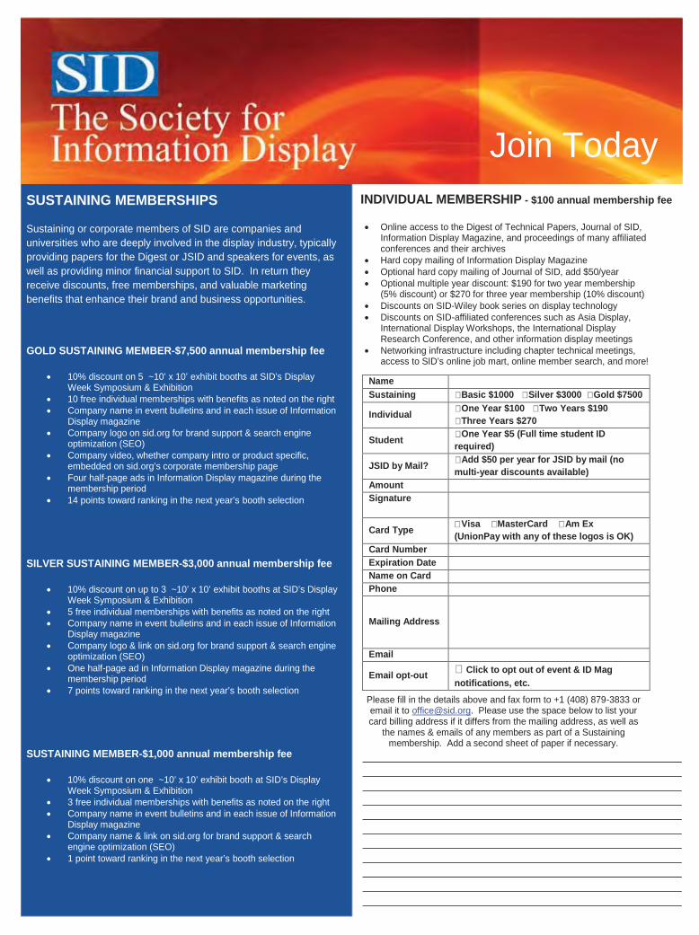
Join Today SUSTAINING MEMBERSHIPS
Sustaining or corporate members of SID are companies and universities who are deeply involved in the display industry, typically providing papers for the Digest or JSID and speakers for events, as well as providing minor financial support to SID. In return they receive discounts, free memberships, and valuable marketing benefits that enhance their brand and business opportunities.
GOLD SUSTAINING MEMBER-$7,500 annual membership fee
10% discount on 5 ~10’ x 10’ exhibit booths at SID’s Display Week Symposium & Exhibition
10 free individual memberships with benefits as noted on the right Company name in event bulletins and in each issue of Information
Display magazine Company logo on sid.org for brand support & search engine
optimization (SEO) Company video, whether company intro or product specific,
embedded on sid.org’s corporate membership page Four half-page ads in Information Display magazine during the
membership period 14 points toward ranking in the next year’s booth selection
SILVER SUSTAINING MEMBER-$3,000 annual membership fee
10% discount on up to 3 ~10’ x 10’ exhibit booths at SID’s Display Week Symposium & Exhibition
5 free individual memberships with benefits as noted on the right Company name in event bulletins and in each issue of Information
Display magazine Company logo & link on sid.org for brand support & search engine
optimization (SEO) One half-page ad in Information Display magazine during the
membership period 7 points toward ranking in the next year’s booth selection
SUSTAINING MEMBER-$1,000 annual membership fee
10% discount on one ~10’ x 10’ exhibit booth at SID’s Display Week Symposium & Exhibition
3 free individual memberships with benefits as noted on the right Company name in event bulletins and in each issue of Information
Display magazine Company name & link on sid.org for brand support & search
engine optimization (SEO) 1 point toward ranking in the next year’s booth selection
INDIVIDUAL MEMBERSHIP - $100 annual membership fee
Online access to the Digest of Technical Papers, Journal of SID, Information Display Magazine, and proceedings of many affiliated conferences and their archives
Hard copy mailing of Information Display Magazine Optional hard copy mailing of Journal of SID, add $50/year Optional multiple year discount: $190 for two year membership
(5% discount) or $270 for three year membership (10% discount) Discounts on SID-Wiley book series on display technology Discounts on SID-affiliated conferences such as Asia Display,
International Display Workshops, the International Display Research Conference, and other information display meetings
Networking infrastructure including chapter technical meetings, access to SID’s online job mart, online member search, and more!
Name Sustaining Basic $1000 Silver $3000 Gold $7500
Individual One Year $100 Two Years $190 Three Years $270
Student One Year $5 (Full time student ID required)
JSID by Mail? Add $50 per year for JSID by mail (no multi-year discounts available)
Amount Signature
Card Type Visa MasterCard Am Ex (UnionPay with any of these logos is OK)
Card Number Expiration Date Name on Card Phone
Mailing Address
Email opt-out Click to opt out of event & ID Mag notifications, etc.
Please fill in the details above and fax form to +1 (408) 879-3833 or email it to [email protected]. Please use the space below to list your card billing address if it differs from the mailing address, as well as
the names & emails of any members as part of a Sustaining membership. Add a second sheet of paper if necessary.
Untitled-1 1 3/22/2013 11:27:13 PM
101 WILLIAMS DRIVE RAMSEY, NJ 07446 • SENSING.KONICAMINOLTA.US • TOLL FREE 888-473-2656 • OUTSIDE USA 201-236-4300101 WILLIAMS DRIVE RAMSEY, NJ 07446 • SENSING.KONICAMINOLTA.US • TOLL FREE 888-473-2656 • OUTSIDE USA 201-236-4300
CS-2000 SPECTRORADIOMETER• Detect extremely low luminances• Quick, highly repeatable measurements• Low polarization effect• Three built-in measuring angles (1°, 0.2°, and 0.1°)
ONLY KONICA MINOLTA OFFERS EASY TO USE SOLUTIONS FOR THE ACCURATE MEASUREMENTS YOU NEED - EVERY TIME.
THE RIGHT INSTRUMENTS FOR THE EXACT RESULTS
CA-2500 2D COLOR ANALYZER • Ideal for evaluation and inspection of display uniformity • Expanded low-luminance measurement range • Improved durability for continuous use applications • Advanced data management software with all new GUI
101 WILLIAMS DRIVE RAMSEY, NJ 07446 • SENSING.KONICAMINOLTA.US • TOLL FREE 888-473-2656 • OUTSIDE USA 201-236-4300101 WILLIAMS DRIVE RAMSEY, NJ 07446 • SENSING.KONICAMINOLTA.US • TOLL FREE 888-473-2656 • OUTSIDE USA 201-236-4300
CS-2000 SPECTRORADIOMETERCS-2000 SPECTRORADIOMETERCS-2000 SPECTRORADIOMETER• Detect extremely low luminances• Quick, highly repeatable measurements• Low polarization effect• Low polarization effect• Three built-in measuring angles (1°, 0.2°, and 0.1°)
• Advanced data management software with all new GUI• Advanced data management software with all new GUI• Advanced data management software with all new GUI• Advanced data management software with all new GUI
VISIT BOOTHDURING SID DISPLAY WEEK
#1124
Display Week 2014SID International Symposium, Seminar & Exhibition
June 1–6, 2014San Diego Convention Center
San Diego, California, USA
www.displayweek.org
Ad p63.indd 1 4/21/2013 5:28:21 PM
Advantech US, Inc.AGC Asahi Glass (Silver Member)AU Optronics Corp.
CDT, Ltd.Chimei InnoluxChunghwa Picture Tubes, Ltd.CLEARink DisplaysCorning Holding Japan
Dawar Technologies, Inc.DisplaySearchDontech (Silver Member)
Elo TouchSystemseMagin Corp.Epoxy TechnologyEuroptec Holding AG
Henkel (China) Investment Co.,Ltd. (Silver Member)
IGNIS Innovation, Inc.Instruments Systems (Gold Member)
I-PEXITRI Display Technology Center
Japan Display, Inc.
Kuraray Co., Ltd.
Logic Technologies, Ltd.
Merck Display Technologies Ltd.Microvision Mitsubishi Chemical Corp.Mitsubishi Electric Corp.
Nano-Proprietary, Inc.NANOSYS
NDF Special Light Products, B.V.NEC Corp.NextWindowNoritake Itron Corp.
OcularOptical Filters USA
Panasonic Corp.Parker ChomericsPrime View International Co.
Qualcomm
Radiant Zemax (Silver Member)ROLIC Technologies, Ltd.
Sartomer USA LLCSharp Corp.Shenzhen Leaguer Optronics Co.,Ltd.
Synape Product DevelopmentLLC
Synaptics
Tannas ElectronicsTatsuta Electric Wire & Cable Co.Teijin Dupont Films Japan Ltd.TLC International
Universal Display Corp.US Micro Products, Inc.
Vestal Electronics A.S.
Westar Display Technologies, Inc.WINTEK Corp.
Abrisa Tchnologies....................61Corning Incorporated ...............59Dawar Technologies ..................21Dexerials America Corporation.................................................61Electronic Assembly ..................27ERG..........................................44EuropTec USA ............................3Futaba Corp. of America...........61Global Lighting Technologies (GLT) ....................................55
Henkel Corp. ...........................C4Instrument Systems...................13Jaco Displays.............................41KOE Americas ..........................59Konica Minolta Sensing Americas ................................63
Merck .........................................7Newhaven Displays International.................................................45NDF Special Lighting Products.................................................27Ocular.......................................12Pixelligent Technologies ............27Radiant Zemax.........................C2Solomon Goldentek Display (SGD)....................................45
Tannas Electronic Displays..........5TFD.........................................C3Xenon .......................................57Wamco......................................57
64 Information Display 3/13
sustaining members index to advertisers
Sales Office
Joseph TomaszewskiAdvertising Sales ManagerWiley111 River StreetHoboken, NJ [email protected]
Advertising Sales Representative
Roland EspinosaWiley111 River StreetHoboken, NJ [email protected]
Sales Office – Europe
George Isaacs12 Park View CourtThe Paddock, Eaton FordSt. Neots, CambridgeshirePE19 7SD U.K.+44-(0)[email protected]
ID Ad Index p64_Layout 1 4/21/2013 5:53 PM Page 64
When you choose Loctite® you’re choosing the best for you and your customers. Our solutions can increase contrast ratio by 400%, increase display ruggedness and extend battery life. Making you the hero of your shareholders, your customers and your customers’ customers.
Thinner. Lighter. Brighter.Loctite® Liquid Optically Clear Adhesives
www.loctite.com/loca • [email protected] • Telephone: China: +86-21-2891 8000 • Japan: +81-45-758 1800 • Korea: +82-2-3279 1700 • Taiwan: +886-2-2227 1988
Cover Lens
Touch Panel Sensor
LOCADirect Bonding
Display Module
LOCACover Lens Bonding
Henkel_LOCA_ADs_forSID_Thinner-Lighter-Brigher_Final_18Mar13.indd 1 3/22/2013 11:03:10 PM
See Us at Display Week 2013, Booth #431