Embed Size (px)
Citation preview
INSTALLATION MANUALFS-527 Finisher
Y111090-1 E-i Installation Manual
Index
FS-527 (d-Color MF360/MF280/MF220)I. Accessory parts ................................................................................................................. 1II. Confirmation before installation .......................................................................................... 2III. Installation procedures ....................................................................................................... 3
FS-527 (d-Color MF451)I. Accessory parts ................................................................................................................. 9II. Confirmation before installation ........................................................................................ 10III. Installation procedures ..................................................................................................... 11

Installation Manual E-ii Y111090-1
This page is intentionally left blank.
E-1
INSTALLATION MANUALFS-527 Finisher
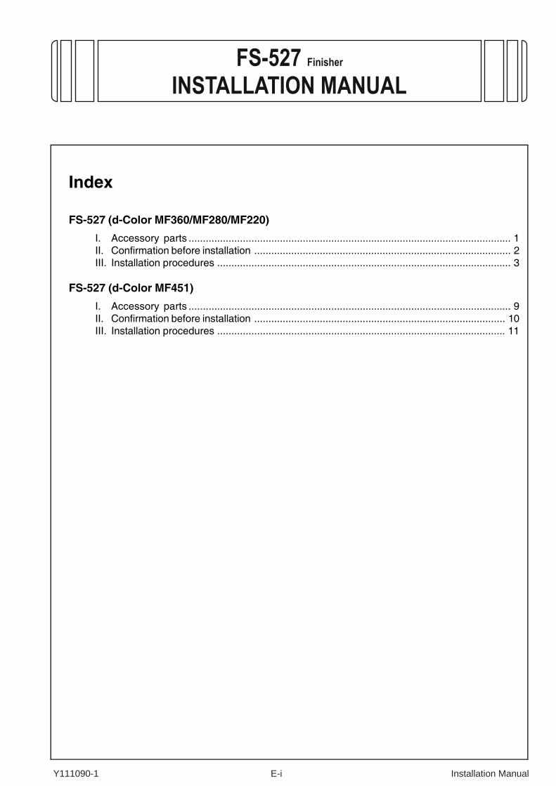
Caution:Lifting the machine in an awkward position or transporting it in a poorly balanced position could result in personal injury. When transporting the machine, assign an adequate number of persons to the job and ensure that each person can take a good position of not being excessively loaded.(mass: approx. 42 kg (92-9/16 lb))
I. Accessory parts
* This part is not used with the finisher.
No. Name Shape Q’ty
1. Finisher
1
2. Horizontal transport unit
1
3. Mounting bracket A*
1
4. Mounting bracket B*
1
5. Mounting bracket C
1
6. Mountingbracket D
1
A0HRIXC001DA
A0HRIXC002DA
A0HRIXC003DA
A0HRIXC004DA
A0HRIXC005DA
A0HRIXC006DA
7. Mountingbracket E
1
8. Exit tray
1
9. Guide plate A*
1
10. Guide plate B*
1
11. Mounting screw1
12. Screw A*(3 × 8 mm) 4
13. Screw B(3 × 16 mm)
4
14. Screw C(4 × 8 mm) 1
15. Screw D(4 × 8 mm) 2
16. Installation manual
1set
No. Name Shape Q’ty
A0HRIXC007DA
A0HRIXC008DA
A0HRIXC009DA
A0HRIXC010DA
A0HRIXC011DA
9646
9J08IXC075DA
9735
4038IXC033DA
4980IXC019DA
Applied Machines: d-Color MF360/MF280/MF220COLOR MFP: 36 ppm/28 ppm/22 ppmProduct Code: A0ED
Y111090-1 Installation Manual

E-2
Note:This manual provides the illustrations of the acces-sory parts and machine that may be slightly differ-ent in shape from yours. In that case, instead of the illustrations, use the appearance of your machine to follow the installation procedure. This does not cause any significant change or problem with the procedure.
II. Confirmation before installation1. To move the finisher, be sure to push it in the
directions of the arrows as shown in the illustra-tion. (Precaution against falling of the finisher).
2. Parts are arranged in a box as shown in the illus-tration.
3. Choose a horizontal and stable floor for installing the machine.
4. The packaging material should not be reused for repacking.
5. When installing the optional punch kit, saddle stitcher, and separator (JS-603), install the punch kit, saddle stitcher, and separator (JS-603) first and then install the finisher.
After unpacking, be sure to get rid of the packaging materials and keep them out of the reach of children.Putting the head in the plastic bag involves danger of suffocation.
A0HRIXC012DA
A0HRIXC046DB
Parts for MF360/MF280/MF220
Common partsParts for MF451
Installation Manual Y111090-1
E-3
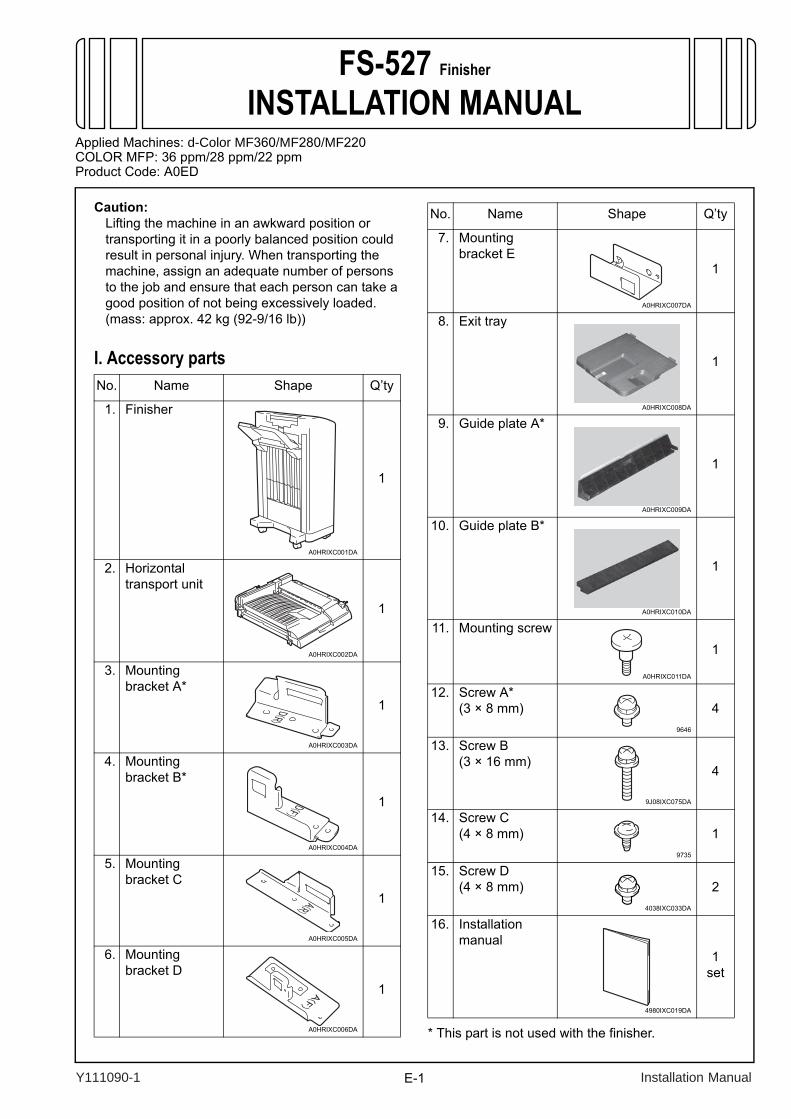
III. Installation procedures1. Turn off the machine and unplug the power cord
from the power outlet.2. Remove the user’s guide holder from the
machine.
3. Remove the output tray if it is mounted on the machine.
* Remove it while pushing the claws of the output tray in the direction of the allow ➀ shown on the illustration and unhook.
4. Peel seals off the machine (two seals).
5. Remove the cover from the main body as shown in the illustration (one screw).
6. Remove the protective tapes of the horizontal transport unit.
7. Attach the furnished mounting plates C (left) and D (right) to the upper left side of the main body (two furnished screw B’s each).
A0HRIXC013DA
A083IXC006DB
➀
➀
A083IXC007DA
Seal
A083IXC033DA
A0HRIXC015DA
A0HRIXC017DA
Y111090-1 Installation Manual
E-4
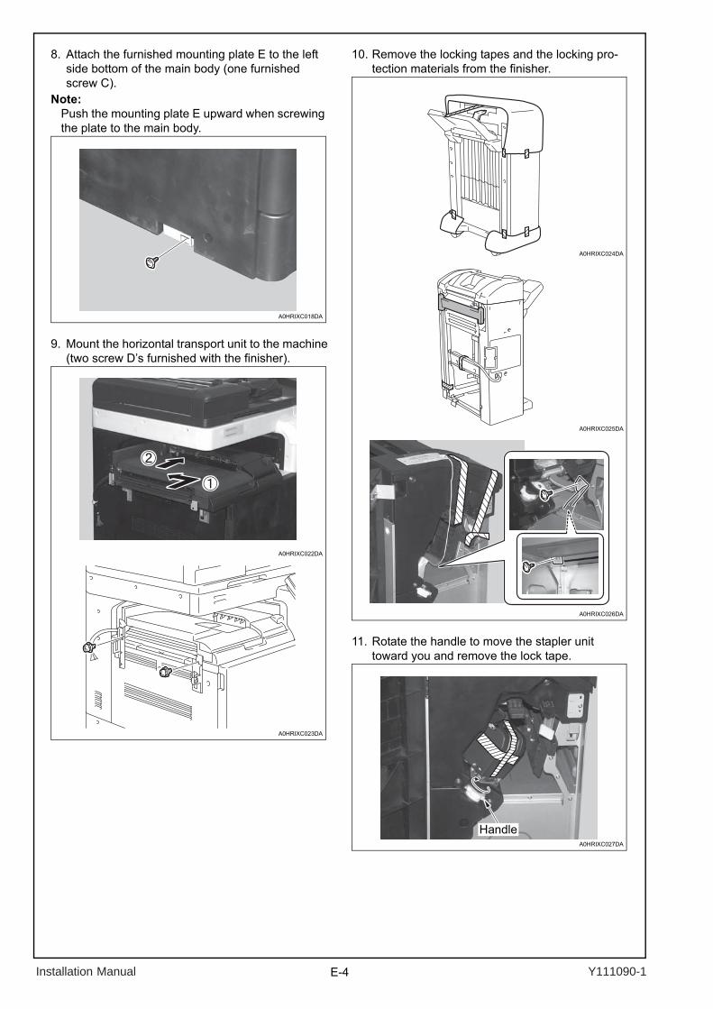
8. Attach the furnished mounting plate E to the left side bottom of the main body (one furnished screw C).
Note:Push the mounting plate E upward when screwing the plate to the main body.
9. Mount the horizontal transport unit to the machine(two screw D’s furnished with the finisher).
10. Remove the locking tapes and the locking pro-tection materials from the finisher.
11. Rotate the handle to move the stapler unit toward you and remove the lock tape.
A0HRIXC018DA
A0HRIXC023DA
A0HRIXC022DA
A0HRIXC025DA
A0HRIXC024DA
A0HRIXC026DA
A0HRIXC027DA
Handle
Installation Manual Y111090-1
E-5
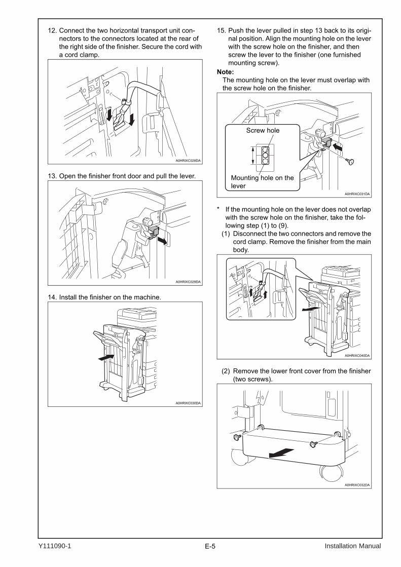
12. Connect the two horizontal transport unit con-nectors to the connectors located at the rear of the right side of the finisher. Secure the cord with a cord clamp.
13. Open the finisher front door and pull the lever.
14. Install the finisher on the machine.
15. Push the lever pulled in step 13 back to its origi-nal position. Align the mounting hole on the lever with the screw hole on the finisher, and then screw the lever to the finisher (one furnished mounting screw).
Note:The mounting hole on the lever must overlap with the screw hole on the finisher.
* If the mounting hole on the lever does not overlap with the screw hole on the finisher, take the fol-lowing step (1) to (9).
(1) Disconnect the two connectors and remove the cord clamp. Remove the finisher from the main body.
(2) Remove the lower front cover from the finisher (two screws).
A0HRIXC028DA
A0HRIXC029DA
A0HRIXC030DA
A0HRIXC031DA
Screw hole
Mounting hole on the lever
A0HRIXC040DA
A0HRIXC032DA
Y111090-1 Installation Manual
E-6
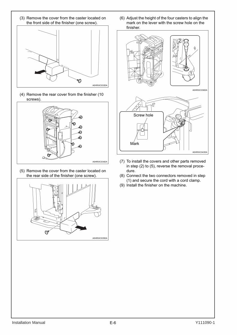
(3) Remove the cover from the caster located on the front side of the finisher (one screw).
(4) Remove the rear cover from the finisher (10 screws).
(5) Remove the cover from the caster located on the rear side of the finisher (one screw).
(6) Adjust the height of the four casters to align the mark on the lever with the screw hole on the finisher.
(7) To install the covers and other parts removed in step (2) to (5), reverse the removal proce-dure.
(8) Connect the two connectors removed in step (1) and secure the cord with a cord clamp.
(9) Install the finisher on the machine.
A0HRIXC033DA
A0HRIXC034DA
A0HRIXC035DA
A0HRIXC036DA
A0HRIXC043DA
Screw hole
Mark
Installation Manual Y111090-1
E-7
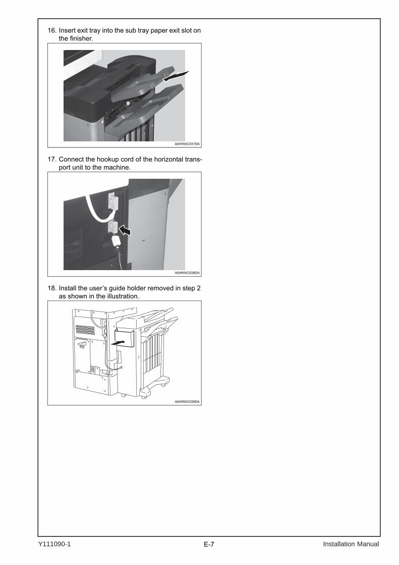
16. Insert exit tray into the sub tray paper exit slot on the finisher.
17. Connect the hookup cord of the horizontal trans-port unit to the machine.
18. Install the user’s guide holder removed in step 2 as shown in the illustration.
A0HRIXC037DA
A0HRIXC038DA
A0HRIXC039DA
Y111090-1 Installation Manual

Y111090-1 E-8 Installation Manual
This page is intentionally left blank.
E-9
INSTALLATION MANUALFS-527 Finisher
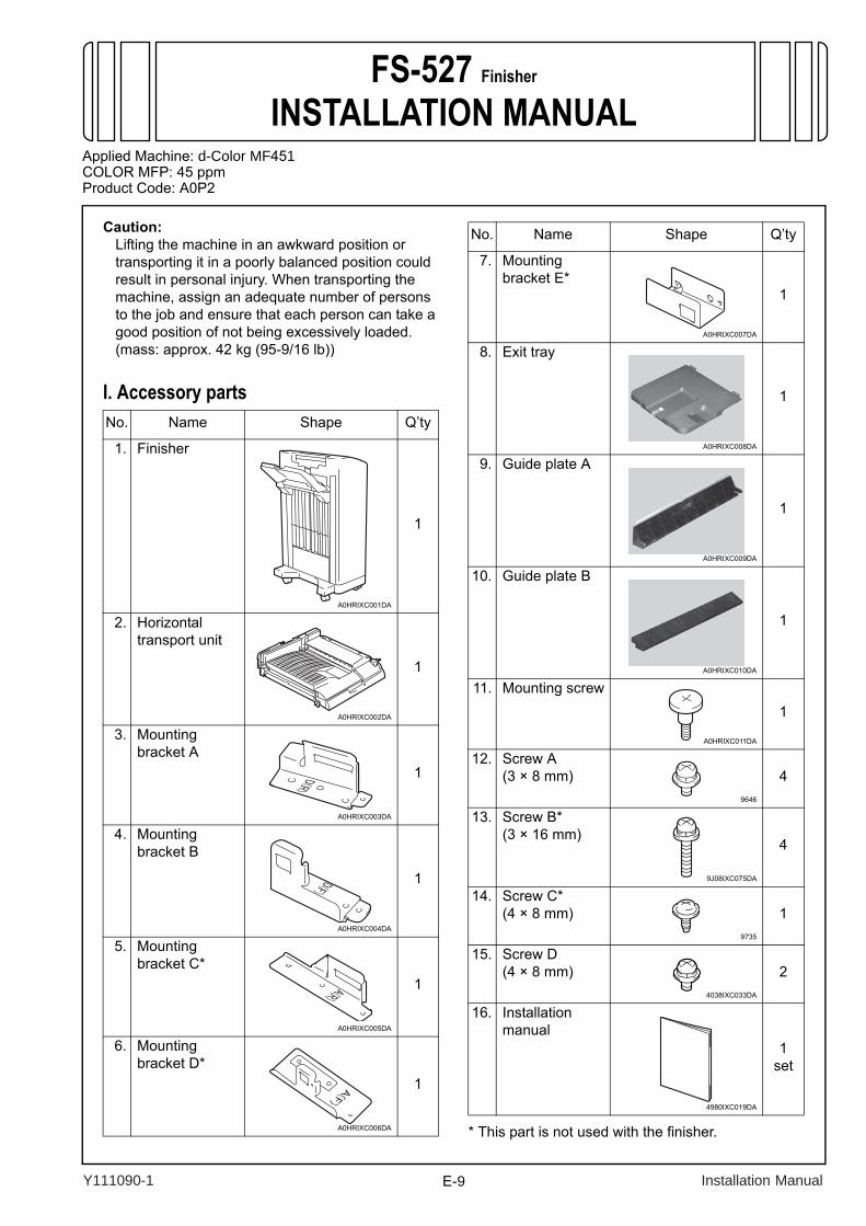
Caution:Lifting the machine in an awkward position or transporting it in a poorly balanced position could result in personal injury. When transporting the machine, assign an adequate number of persons to the job and ensure that each person can take a good position of not being excessively loaded.(mass: approx. 42 kg (95-9/16 lb))
I. Accessory parts
* This part is not used with the finisher.
No. Name Shape Q’ty
1. Finisher
1
2. Horizontal transport unit
1
3. Mounting bracket A
1
4. Mounting bracket B
1
5. Mounting bracket C*
1
6. Mountingbracket D*
1
A0HRIXC001DA
A0HRIXC002DA
A0HRIXC003DA
A0HRIXC004DA
A0HRIXC005DA
A0HRIXC006DA
7. Mountingbracket E*
1
8. Exit tray
1
9. Guide plate A
1
10. Guide plate B
1
11. Mounting screw1
12. Screw A (3 × 8 mm) 4
13. Screw B*(3 × 16 mm)
4
14. Screw C*(4 × 8 mm) 1
15. Screw D (4 × 8 mm) 2
16. Installation manual
1set
No. Name Shape Q’ty
A0HRIXC007DA
A0HRIXC008DA
A0HRIXC009DA
A0HRIXC010DA
A0HRIXC011DA
9646
9J08IXC075DA
9735
4038IXC033DA
4980IXC019DA
Applied Machine: d-Color MF451COLOR MFP: 45 ppmProduct Code: A0P2
Y111090-1 Installation Manual
E-10
Note:This manual provides the illustrations of the acces-sory parts and machine that may be slightly differ-ent in shape from yours. In that case, instead of the illustrations, use the appearance of your machine to follow the installation procedure. This does not cause any significant change or problem with the procedure.
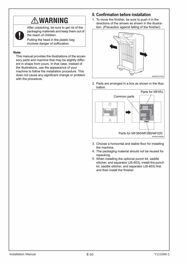
II. Confirmation before installation1. To move the finisher, be sure to push it in the
directions of the arrows as shown in the illustra-tion. (Precaution against falling of the finisher).
2. Parts are arranged in a box as shown in the illus-tration.
3. Choose a horizontal and stable floor for installing the machine.
4. The packaging material should not be reused for repacking.
5. When installing the optional punch kit, saddle stitcher, and separator (JS-603), install the punch kit, saddle stitcher, and separator (JS-603) first and then install the finisher.
After unpacking, be sure to get rid of the packaging materials and keep them out of the reach of children.Putting the head in the plastic bag involves danger of suffocation.
A0HRIXC012DA
A0HRIXC046DB
Parts for MF360/MF280/MF220
Common partsParts for MF451
Installation Manual Y111090-1
E-11
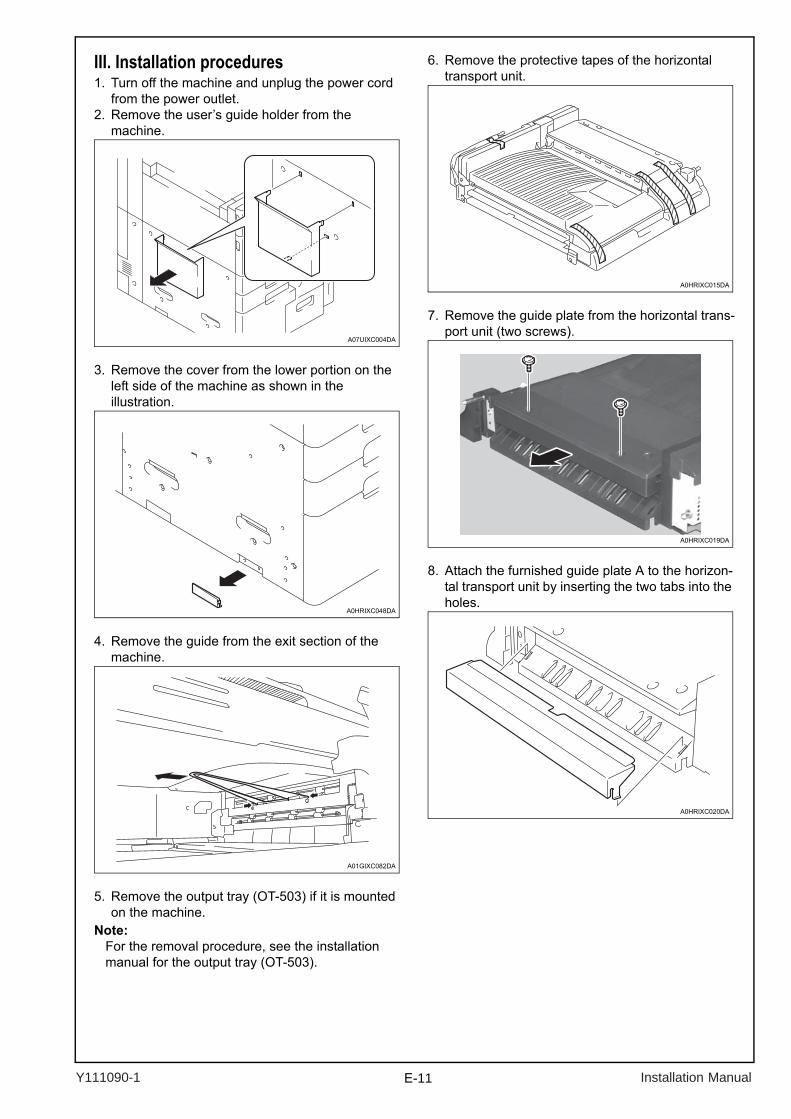
III. Installation procedures1. Turn off the machine and unplug the power cord
from the power outlet.2. Remove the user’s guide holder from the
machine.
3. Remove the cover from the lower portion on the left side of the machine as shown in the illustration.
4. Remove the guide from the exit section of the machine.
5. Remove the output tray (OT-503) if it is mounted on the machine.
Note:For the removal procedure, see the installationmanual for the output tray (OT-503).
6. Remove the protective tapes of the horizontal transport unit.
7. Remove the guide plate from the horizontal trans-port unit (two screws).
8. Attach the furnished guide plate A to the horizon-tal transport unit by inserting the two tabs into the holes.
A07UIXC004DA
A0HRIXC048DA
A01GIXC082DA
A0HRIXC015DA
A0HRIXC019DA
A0HRIXC020DA
Y111090-1 Installation Manual
E-12
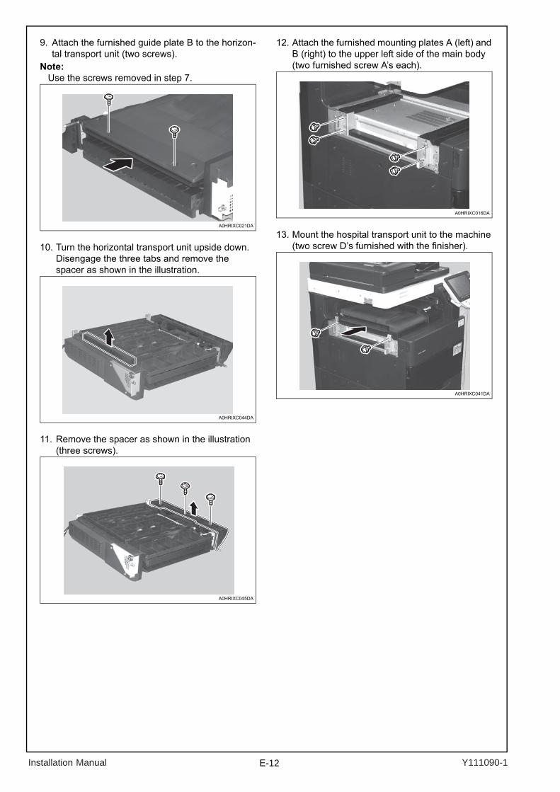
9. Attach the furnished guide plate B to the horizon-tal transport unit (two screws).
Note:Use the screws removed in step 7.
10. Turn the horizontal transport unit upside down. Disengage the three tabs and remove the spacer as shown in the illustration.
11. Remove the spacer as shown in the illustration (three screws).
12. Attach the furnished mounting plates A (left) and B (right) to the upper left side of the main body (two furnished screw A’s each).
13. Mount the hospital transport unit to the machine (two screw D’s furnished with the finisher).
A0HRIXC021DA
A0HRIXC044DA
A0HRIXC045DA
A0HRIXC016DA
A0HRIXC041DA
Installation Manual Y111090-1
E-13
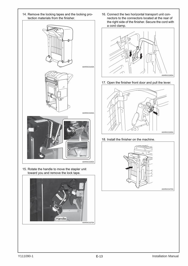
14. Remove the locking tapes and the locking pro-tection materials from the finisher.
15. Rotate the handle to move the stapler unit toward you and remove the lock tape.
16. Connect the two horizontal transport unit con-nectors to the connectors located at the rear of the right side of the finisher. Secure the cord with a cord clamp.
17. Open the finisher front door and pull the lever.
18. Install the finisher on the machine.
A0HRIXC025DA
A0HRIXC024DA
A0HRIXC026DA
A0HRIXC027DA
Handle
A0HRIXC028DA
A0HRIXC029DA
A0HRIXC047DA
Y111090-1 Installation Manual
E-14
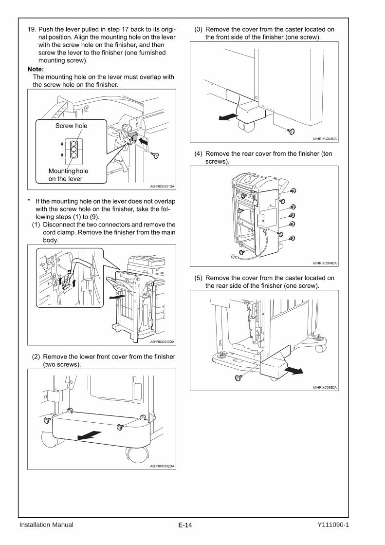
19. Push the lever pulled in step 17 back to its origi-nal position. Align the mounting hole on the lever with the screw hole on the finisher, and then screw the lever to the finisher (one furnished mounting screw).
Note:The mounting hole on the lever must overlap with the screw hole on the finisher.
* If the mounting hole on the lever does not overlap with the screw hole on the finisher, take the fol-lowing steps (1) to (9).
(1) Disconnect the two connectors and remove the cord clamp. Remove the finisher from the main body.
(2) Remove the lower front cover from the finisher (two screws).
(3) Remove the cover from the caster located on the front side of the finisher (one screw).
(4) Remove the rear cover from the finisher (ten screws).
(5) Remove the cover from the caster located on the rear side of the finisher (one screw).
A0HRIXC031DA
Screw hole
Mounting hole on the lever
A0HRIXC040DA
A0HRIXC032DA
A0HRIXC033DA
A0HRIXC034DA
A0HRIXC035DA
Installation Manual Y111090-1
E-15
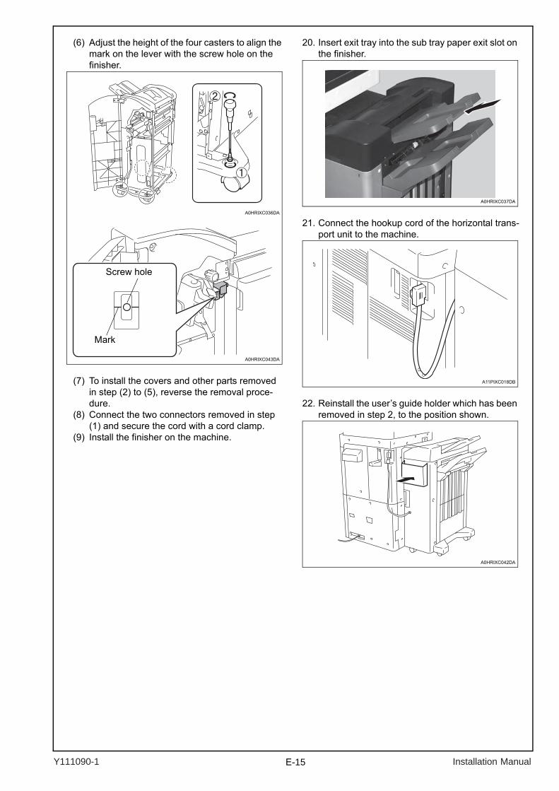
(6) Adjust the height of the four casters to align the mark on the lever with the screw hole on the finisher.
(7) To install the covers and other parts removed in step (2) to (5), reverse the removal proce-dure.
(8) Connect the two connectors removed in step (1) and secure the cord with a cord clamp.
(9) Install the finisher on the machine.
20. Insert exit tray into the sub tray paper exit slot on the finisher.
21. Connect the hookup cord of the horizontal trans-port unit to the machine.
22. Reinstall the user’s guide holder which has been removed in step 2, to the position shown.
A0HRIXC036DA
A0HRIXC043DA
Screw hole
Mark
A0HRIXC037DA
A11PIXC018DB
A0HRIXC042DA
Y111090-1 Installation Manual