Embed Size (px)
Citation preview
Operating Manual - English
FUJITSU Server PRIMERGY TX1330 M2 Operating Manual
Edition November 2015
Comments… Suggestions… Corrections…The User Documentation Department would like toknow your opinion of this manual. Your feedback helpsus optimize our documentation to suit your individual needs.
Feel free to send us your comments by e-mail to [email protected].
Certified documentation according to DIN EN ISO 9001:2008To ensure a consistently high quality standard anduser-friendliness, this documentation was created tomeet the regulations of a quality management system which complies with the requirements of the standardDIN EN ISO 9001:2008.
cognitas. Gesellschaft für Technik-Dokumentation mbHwww.cognitas.de
Copyright and TrademarksCopyright © 2015 Fujitsu Technology Solutions GmbH.
All rights reserved.Delivery subject to availability; right of technical modifications reserved.
All hardware and software names used are trademarks of their respective manufacturers.
– The contents of this manual may be revised without prior notice.
– Fujitsu assumes no liability for damages to third party copyrights or other rights arising from the use of any information in this manual.
– No part of this manual may be reproduced in any without the prior written permission of Fujitsu.
Microsoft, Windows, Windows Server, and Hyper V are trademarks or registered trademarks of Microsoft Corporation in the USA and other countries.
Intel and Xeon are trademarks or registered trademarks of Intel Corporation or its subsidiaries in the USA and other countries.
TX1330 M2 Operating Manual
Before reading this manual
For your safety
This manual contains important information for safely and correctly using this product.
Carefully read the manual before using this product. Pay particular attention to the accompanying manual "Safety Notes and Regulations" and ensure these safety notes are understood before using the product. Keep this manual and the manual "Safety Notes and Regulations" in a safe place for easy reference while using this product.
Radio interference
This product is a "Class A" ITE (Information Technology Equipment). In a domestic environment this product may cause radio interference, in which case the user may be required to take appropriate measures. VCCI-A
Aluminum electrolytic capacitors
The aluminum electrolytic capacitors used in the product's printed circuit board assemblies and in the mouse and keyboard are limited-life components. Use of these components beyond their operating life may result in electrolyte leakage or depletion, potentially causing emission of foul odor or smoke.
As a guideline, in a normal office environment (25°C) operating life is not expected to be reached within the maintenance support period (5 years). However, operating life may be reached more quickly if, for example, the product is used in a hot environment. The customer shall bear the cost of replacing replaceable components which have exceeded their operating life. Note that these are only guidelines, and do not constitute a guarantee of trouble-free operation during the maintenance support period.
High safety use
This product has been designed and manufactured to be used in commercial and/or industrial areas as a server.
When used as visual display workplace, it must not be placed in the direct field of view to avoid incommoding reflections (applies only to TX server systems).
The device has not been designed or manufactured for uses which demand an extremely high level of safety and carry a direct and serious risk of life or body if such safety cannot be assured.
Operating Manual TX1330 M2
These uses include control of nuclear reactions in nuclear power plants, automatic airplane flight control, air traffic control, traffic control in mass transport systems, medical devices for life support, and missile guidance control in weapons systems (hereafter, "high safety use"). Customers should not use this product for high safety use unless measures are in place for ensuring the level of safety demanded of such use. Please consult the sales staff of Fujitsu if intending to use this product for high safety use.
Measures against momentary voltage drop
This product may be affected by a momentary voltage drop in the power supply caused by lightning. To prevent a momentary voltage drop, use of an AC uninterruptible power supply is recommended.
(This notice follows the guidelines of Voltage Dip Immunity of Personal Computer issued by JEITA, the Japan Electronics and Information Technology Industries Association.)
Technology controlled by the Foreign Exchange and Foreign Trade Control Law of Japan
Documents produced by Fujitsu may contain technology controlled by the Foreign Exchange and Foreign Trade Control Law of Japan. Documents which contain such technology should not be exported from Japan or transferred to non-residents of Japan without first obtaining authorization in accordance with the above law.
Harmonic Current Standards
This product conforms to harmonic current standard JIS C 61000-3-2.
Only for the Japanese market: About SATA hard disk drives
The SATA version of this server supports hard disk drives with SATA / BC-SATA storage interfaces. Please note that the usage and operation conditions differ depending on the type of hard disk drive used.
Please refer to the following internet address for further information on the usage and operation conditions of each available type of hard disk drive:
http://jp.fujitsu.com/platform/server/primergy/harddisk/
TX1330 M2 Operating Manual
Contents
1 Introduction . . . . . . . . . . . . . . . . . . . . . . . . . . . . 9
1.1 Concept and target groups for this manual . . . . . . . . . . 9
1.2 Documentation overview . . . . . . . . . . . . . . . . . . . 10
1.3 Notational conventions . . . . . . . . . . . . . . . . . . . . 11
2 Functional overview . . . . . . . . . . . . . . . . . . . . . . 13
2.1 Features . . . . . . . . . . . . . . . . . . . . . . . . . . . . . 13
2.2 Server specification . . . . . . . . . . . . . . . . . . . . . . 23
3 Installation steps, overview . . . . . . . . . . . . . . . . . . 29
4 Important information . . . . . . . . . . . . . . . . . . . . . 31
4.1 Safety instructions . . . . . . . . . . . . . . . . . . . . . . . 31
4.2 ENERGY STAR . . . . . . . . . . . . . . . . . . . . . . . . . 39
4.3 CE conformity . . . . . . . . . . . . . . . . . . . . . . . . . 39
4.4 FCC Class A Compliance Statement . . . . . . . . . . . . . 40
4.5 Transporting the server . . . . . . . . . . . . . . . . . . . . 41
4.6 Notes on installing the server in the rack . . . . . . . . . . . 41
4.7 Environmental protection . . . . . . . . . . . . . . . . . . . 43
5 Hardware installation . . . . . . . . . . . . . . . . . . . . . . 45
5.1 Unpacking the server . . . . . . . . . . . . . . . . . . . . . 46
5.2 Setting up the floorstand model . . . . . . . . . . . . . . . . 47
5.3 Installing/removing the rack model . . . . . . . . . . . . . . 48
5.4 Connecting devices to the server . . . . . . . . . . . . . . . 50
Operating Manual TX1330 M2
Contents
5.5 Connecting the server to the mains . . . . . . . . . . . . . . 515.5.1 Using cable ties (standard PSU) . . . . . . . . . . . . . . . . . 525.5.2 Using cable ties (hot-plug PSU) . . . . . . . . . . . . . . . . . 53
5.6 Notes on connecting/disconnecting cables . . . . . . . . . . 54
6 Starting up and operation . . . . . . . . . . . . . . . . . . . . 57
6.1 Access to the drives (floorstand model) . . . . . . . . . . . . 576.1.1 Enabling access to the accessible drives . . . . . . . . . . . . . 576.1.2 Access to the HDD modules (floorstand model) . . . . . . . . . 59
6.2 Control elements and indicators . . . . . . . . . . . . . . . . 606.2.1 Front of the server . . . . . . . . . . . . . . . . . . . . . . . . 606.2.1.1 Control elements . . . . . . . . . . . . . . . . . . . . . . . 616.2.1.2 Indicators on the control panel . . . . . . . . . . . . . . . . 626.2.1.3 ID card . . . . . . . . . . . . . . . . . . . . . . . . . . . . . 646.2.1.4 Indicators on the drives . . . . . . . . . . . . . . . . . . . . 656.2.2 Rear of server . . . . . . . . . . . . . . . . . . . . . . . . . . . 666.2.2.1 Indicators on the connector panel . . . . . . . . . . . . . . . 66
6.3 Switching the server on and off . . . . . . . . . . . . . . . . 71
6.4 Configuring the server . . . . . . . . . . . . . . . . . . . . . 736.4.1 Configuring the onboard SATA controller . . . . . . . . . . . . . 736.4.2 Configuring the SAS/SATA RAID controller
(PCIe expansion card) . . . . . . . . . . . . . . . . . . . . . . 746.4.3 Configuring the server and installing the operating system
with the ServerView Installation Manager . . . . . . . . . . . . . 756.4.4 Configuring the server and installing the operating system
without the ServerView Installation Manager . . . . . . . . . . . 76
6.5 Cleaning the server . . . . . . . . . . . . . . . . . . . . . . . 77
7 Property and data protection . . . . . . . . . . . . . . . . . . 79
7.1 BIOS Setup security functions . . . . . . . . . . . . . . . . . 79
8 Troubleshooting and tips . . . . . . . . . . . . . . . . . . . . 81
8.1 Power-on indicator remains unlit . . . . . . . . . . . . . . . . 81
8.2 Server switches itself off . . . . . . . . . . . . . . . . . . . . 82
TX1330 M2 Operating Manual
Contents
8.3 Screen remains blank . . . . . . . . . . . . . . . . . . . . . 82
8.4 Flickering stripes on monitor screen . . . . . . . . . . . . . 83
8.5 No screen display or display drifts . . . . . . . . . . . . . . 83
8.6 No mouse pointer displayed on screen . . . . . . . . . . . . 83
8.7 Incorrect date and time . . . . . . . . . . . . . . . . . . . . 84
8.8 Drives reported as “dead” when starting system . . . . . . 84
8.9 Added drive reported as defective . . . . . . . . . . . . . . 84
8.10 Error message on screen . . . . . . . . . . . . . . . . . . . 85
8.11 Expansion cards or onboard devices not recognized . . . . 85
8.12 Temperature warning . . . . . . . . . . . . . . . . . . . . . . 85
8.13 No effect of keyboard or mouse . . . . . . . . . . . . . . . . 85
8.14 Optical drive cannot read data . . . . . . . . . . . . . . . . 86

Operating Manual TX1330 M2
Contents
TX1330 M2 Operating Manual 9
1 Introduction
The PRIMERGY TX1330 M2 is the ideal robust and cost-efficient server for small and medium-sized businesses (SMB) or branch offices. It offers best Intel® Xeon® E3 performance and solid expandability thanks to hot-plug storage drives.
The optionally redundant power supply and a choice of different RAID controllers ensure high availability and peace of mind. Thanks to its compact housing and extremely low operating noise the server is ideally suited for showrooms or offices, for example under the desk. The optional support of legacy PCI adapter cards makes the PRIMERGY TX1330 M2 optimally suited for special solutions, such as telephone or security systems.
Furthermore, the comprehensive Fujitsu ServerView® Suite provides support for administrators during server installation, deployment and administration. The PRIMERGY TX1330 M2: an excellent long-term investment.
The floorstand model can be converted to a rack model using an optional conversion kit. The rack model occupies 4 height units in the rack.
1.1 Concept and target groups for this manual
This operating manual describes how to install, set up and operate your server.
This operating manual is intended for those responsible for installing the hardware and ensuring that the system runs smoothly. It contains all the information you need to put your PRIMERGY TX1330 M2 into operation.
To understand the various expansion options, you will need to be familiar with the fields of hardware and data transmission and you will require a basic knowledge of the underlying operating system.
10 Operating Manual TX1330 M2
Introduction
1.2 Documentation overview
More information on your PRIMERGY TX1330 M2 can be found in the following documents:
– "Quick Start Hardware - FUJITSU Server PRIMERGY TX1330 M2"
– "ServerView Quick Start Guide"
– "Safety Notes and Regulations" manual" 安全上のご注意 " for the Japanese market
– "Warranty" manual" 保証書 " for the Japanese market
– "ServerView Suite Local Service Concept - LSC" manual
– "Returning used devices" manual and "Service Desk" leaflet" サポート&サービス " for the Japanese market
– "FUJITSU Server PRIMERGY TX1330 M2 Upgrade and Maintenance Manual"
– "D3373 BIOS Setup Utility for FUJITSU Server PRIMERGY TX1330 M2 Reference Manual"
I All documentation on PRIMERGY hardware and ServerView software is available online from the Fujitsu manuals server at:
– For the EMEA market: http://manuals.ts.fujitsu.com– For the Japanese market:
http://jp.fujitsu.com/platform/server/primergy/manual
The complete PRIMERGY documentation set can also be downloaded as a DVD ISO image at:
– For the EMEA market: ftp://ftp.ts.fujitsu.com/images/serverview/manuals– For the Japanese market: http://jp.fujitsu.com/primergy/downloads
I For the Japanese market:
Before using the product, please check for additional information that may be available under the following URL:http://jp.fujitsu.com/platform/server/primergy/products/note/
TX1330 M2 Operating Manual 11
Introduction
Further sources of information:
– ServerView Suite Glossary– Manual for the monitor– Documentation for the boards and drives– Operating system documentation– Information files in your operating system
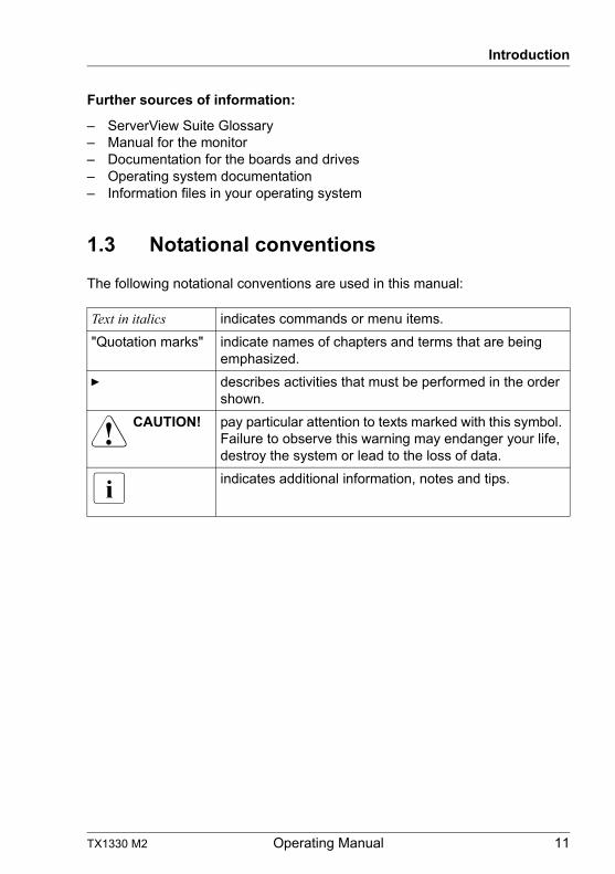
1.3 Notational conventions
The following notational conventions are used in this manual:
Text in italics indicates commands or menu items.
"Quotation marks" indicate names of chapters and terms that are being emphasized.
Ê describes activities that must be performed in the order shown.
V CAUTION! pay particular attention to texts marked with this symbol. Failure to observe this warning may endanger your life, destroy the system or lead to the loss of data.
I indicates additional information, notes and tips.
12 Operating Manual TX1330 M2
Introduction
TX1330 M2 Operating Manual 13
2 Functional overview
This section provides information on the features and technical data of the PRIMERGY TX1330 M2 server. For information on key characteristics and layout of the system board, see the "FUJITSU Server PRIMERGY TX1330 M2 Upgrade and Maintenance Manual".
2.1 Features
I For the latest information on optional products provided for the TX1330 M2 see the configurator of the server:
http://ts.fujitsu.com/products/standard_servers/index.html (for the global market)
http://jp.fujitsu.com/platform/server/primergy/system/ (for the Japanese market)
Intel® Xeon®, Pentium®, Celeron® or Core™ i3 processor
The server has an Intel® Xeon®, Pentium®, Celeron® or Core™ i3 processor for high-speed data processing.
Customer Self Service (CSS)
The PRIMERGY Customer Self Service (CSS) concept enables you to identify and replace the affected component yourself in the case of certain error scenarios.
In the CSS concept, you can replace the following components yourself in the event of an error:
– Hot-plug HDD/SSD modules
– Hot-plug power supply units
– Memory modules
– Expansion cards
For information on replacing these components, see the "FUJITSU Server PRIMERGY TX1330 M2 Upgrade and Maintenance Manual".
CSS indicators on the control panel and on the back of the PRIMERGY server provide you with information if a CSS event arises.
14 Operating Manual TX1330 M2
Functional overview
You can also fit your server with a ServerView Local Service Panel, which enables you to identify the type of component affected by the error directly on the server.
In addition, CSS errors are displayed in the ServerView Operations Manager, the server management software from Fujitsu.
In the event of errors, the ServerView Operations Manager refers you directly to the affected component and its order information in the Illustrated Spares catalog of the server in question. (This feature is not available for the Japanese market.)
I Further information on the CSS concept is provided in the "PRIMERGY ServerView Suite Local Service Concept - LSC" manual.
System board
The features of the system board are described in the "FUJITSU Server PRIMERGY TX1330 M2 Upgrade and Maintenance Manual" for the hardware and in the "D3373 BIOS Setup Utility for FUJITSU Server PRIMERGY TX1330 M2 Reference Manual" for the firmware.
Trusted Platform Module (TPM)
A Trusted Platform Module (TPM) for safer storage of keys can be implemented as an option. This module enables programs from third party manufacturers to store key information (e.g. drive encryption using Windows Bitlocker Drive Encryption).
The TPM is activated via the BIOS system (for more information, refer to the "D3373 BIOS Setup Utility for FUJITSU Server PRIMERGY TX1330 M2 Reference Manual").
V CAUTION!
– When using the TPM, note the program descriptions provided by the third party manufacturers.
– You must also create a backup of the TPM content. To do this, follow the third party manufacturer's instructions. Without this backup, if the TPM or the system board is faulty you will not be able to access your data.
– If a failure occurs, please inform your service about the TPM activation before it takes any action, and be prepared to provide them with your backup copies of the TPM content.
TX1330 M2 Operating Manual 15
Functional overview
Hard disk drives
The server is shipped with one of the following drive cages:
– For up to twelve 3.5-inch SAS/SATA hard disk drives:
Up to twelve 3.5-inch SAS/SATA HDD modules can be used in the drive cage. Each HDD module can accommodate an SAS/SATA hard disk drive with a maximum height of 1 inch. The HDD modules are connected to the SAS/SATA backplane wirelessly. This allows HDD modules to be plugged in or pulled out easily.
I Up to four SATA hard disk drives are controlled by the onboard SATA controller. An additional SAS/SATA RAIDcontroller must be installed to control additional SATA hard disk drives or SAS hard disk drives.
I Configurations with Eco SATA can only be mixed with BC SATA HDD type. SAS and BC SATA drives with the same size can be mixed, but not used in the same logical RAID volume.
– For up to twenty four 2.5-inch SAS/SATA hard disk drives or 2.5-inch SATA SSD drives:
Up to twenty four 2.5-inch HDD/SSD modules can be used in the drive cage. Each module can accommodate SAS/SATA hard disk drive or an SATA SSD drive with a 2.5-inch format. The HDD/SSD modules are connected to the SAS/SATA backplane wirelessly. This allows modules to be plugged in or pulled out easily.
I Up to eight SAS/SATA hard disk drives are controlled by the SAS/SATA RAID controller already installed.
I Configurations with Eco SATA can only be mixed with BC SATA HDD type. SAS and BC SATA drives with the same size can be mixed, but not used in the same logical RAID volume.
Hybrid configurations of SATA HDD and SATA SSD modules are supported.
If the server has the corresponding RAID configuration, the HDD modules can also be replaced during operation.
Onboard SATA controller
A SATA controller is integrated on the system board; up to four SATA hard disk drives can be connected to the controller. The LSI Embedded MegaRAID software (SATA Software RAID) supports RAID levels 0, 1 and 10.
16 Operating Manual TX1330 M2
Functional overview
For more information on configuring the controller, see section "Configuring the onboard SATA controller" on page 73.
SAS/SATA RAID controller
The server is available with the following SAS/SATA RAID controllers for operating the internal SAS/SATA hard disk drives:
– Modular RAID 0/1 controller with "Integrated RAID" (SAS IR) for SAS3.0
RAID levels 0 and 1 are supported for internal hard disk drive configurations.
– Modular RAID 0/1 controller with "MegaRAID functionality" (SAS MegaRAID) for SAS3.0
RAID levels 0, 1, 10, 1E, 5 and 50 are supported for internal hard disk drive configurations.
– Modular RAID 5/6 controller with "MegaRAID functionality" (SAS MegaRAID) for SAS3.0
RAID levels 0, 1, 10, 1E, 5, 50, 6 and 60 are supported for internal hard disk drive configurations. As an option, a Flash backup unit (FBU) can save the memory content even if the power fails. Cache memory size of 1GB or 2GB are available.
I For more information on configuring the controller, see section "Configuring the SAS/SATA RAID controller (PCIe expansion card)" on page 74.
Further information on SAS/SATA RAID controllers is provided in the "Modular RAID Controller Installation Guide" (on the Fujitsu manuals server under x86 Servers - Expansion Cards - Storage Adapters - LSI RAID / SCSI Controllers).
Further information on other SAS/SATA RAID controllers (e.g. for operating external SAS/SATA hard disk drives or tape drives) is available on the Fujitsu manuals server under x86 Servers - Expansion Cards - Storage Adapters - LSI RAID / SCSI Controllers.
TX1330 M2 Operating Manual 17
Functional overview
Accessible drives
The server has three 5.25-inch bays that can be used in various ways:
The individual bays can be equipped with any 3.5-inch drives (height:1.6 inch).
You can install a multibay (DVD-LSD/LSP) in the top bay. You can install a slimline DVD drive and the ServerView Local Service Display or ServerView Local Service Panel in the multibay (DVD-LSD/LSP).
As an option for the top bay, a slimline DVD / backup drive cage is available.
I Please note the following:
– A DVD drive must have been installed in order to operate the server.– The accessible drives cannot be replaced during operation.– You are required to open the drive cover of system when you access
to the 5.25-inch drives.
Power supply
In its basic configuration the server has a standard power supply unit or a hot-plug power supply unit that adjusts automatically to any mains voltage in the range 100 V - 240 V. Besides the hot-plug power supply unit, a second hot-plug power supply unit can be installed optionally to serve as a redundant power supply. If one power supply unit fails, the second power supply unit in the redundant configuration ensures operation can continue uninterrupted.
Fujitsu battery unit
FJBU behaves as a modular UPS in the server. When power fail happened, the server can operate by FJBU battery for a while.
FJBU supports hot plugging, and can be replaced during operation.
You can download the management software (FJBU management software) for the following OS:
– Windows Server 2012 R2, Windows Server 2012,
– Windows Server 2008 R2 SP1, Windows Server 2008 R2 SP2
I FJBU (Fujitsu battery unit) management software is not available in Red Hat Enterprise Linux environment. Please use the IPMI function at Linux environment.
18 Operating Manual TX1330 M2
Functional overview
Cool-safe® Advanced Thermal Design
The Cool-safe® Advanced Thermal Design option allows you to operate the system within a wider temperature range of 5 °C to 40 °C.
V CAUTION
In a system that has the Cool-safe® Advanced Thermal Design Option, only components that support the higher operating range may be installed. Further information on this is available in the configurator.
High level of availability and data security
When memory data is accessed, 1-bit errors are identified in the main memory and automatically corrected with the error correcting code (ECC) method.
ASR&R (Automatic Server Reconfiguration and Restart) restarts the system in the event of an error and automatically "hides" the defective system components.
The PDA (Prefailure Detection and Analysis) technology from Fujitsu analyzes and monitors all components that are critical for system reliability.
A RAID controller supports different RAID levels and increase the availability and data security of the system.
The hot-plug HDD modules provide additional availability.
This option can only be ordered from the manufacturer and is indicated by the logo on the identification rating plate.
TX1330 M2 Operating Manual 19
Functional overview
iRMC S4 with integrated management LAN connector
The iRMC S4 (integrated Remote Management Controller) is a Baseboard Management Controller (BMC) with integrated management LAN connector and expanded functionality that was previously only available with additional plug-in cards. In this way, the iRMC S4 enables complete control of PRIMERGY servers, regardless of system status, and thus particularly the control of PRIMERGY servers that are in the "out-of-band" system status.
Major functions supported by the iRMC S4 include the following:
● Browser access via iRMC S4´s own Web server
● Secure communication (SSH, SSL)
● Power Management for the managed server (depending on its system status)
● Power Consumption Management
● Connecting virtual drives as remote storage
● Text-based and graphic console bypass (Advanced Video Redirection)
● Remote Storage
● Command Line Interface (CLI)
● Simple, interactive or script-based iRMC S4configuration
● Customer Self Service (CSS)
● iRMC S4´s own user management
● Multi-computer, global iRMC S4 user administration using an LDAP Directory Service
● Automatic network configuration via DNS / DHCP
● Power supply of the iRMC S4 via the system standby supply
● Full-coverage alarm management
● System Event Log (SEL) reading and processing
● IPMI support
● CIM / WS-MAN support
● Internal Event Log for user login / logout auditing
20 Operating Manual TX1330 M2
Functional overview
More information about the iRMC S4 can be found in the "iRMC S4 - integrated Remote Management Controller" user guide (on the Fujitsu manuals server under x86 Servers - Software - ServerView Suite - Out-Of-Band Management).
Server management
Server management is implemented using the ServerView Operations Manager supplied and the PDA (Prefailure Detection and Analysis) technology from Fujitsu. PDA reports the threat of a system error or overload at an early stage, allowing preventive measures to be taken.
The ServerView Operations Manager enables the management of all PRIMERGY servers in the network via a central console. The ServerView Operations Manager supports the following functions:
● Round-the-clock monitoring, regardless of server status
● High-performance, graphical console bypass (AVR) protected by HTTPS/SSL (128 bit)
● Remote storage via USB
● Remote power on
● Intrusion detection in the floorstand model
● Temperature monitoring of the CPU and the surrounding area
● Detailed status and error reports for processors and main memory
● Watchdog timer for Automatic Server Reconfiguration and Restart (ASR&R) in the event that memory modules or processors fail
● Power monitoring
● End-of-life monitoring of fans with prompt notification before failure
● Watchdog timer for monitoring the operating system with ASR&R
Further information on the ServerView Operations Manager is provided in the associated documentation.
TX1330 M2 Operating Manual 21
Functional overview
ServerView Installation Manager
You can configure the PRIMERGY server quickly and precisely with the ServerView Installation Manager software provided. User-guided menus are available for installing the server operating system (for further details see section "Configuring the server" on page 73).
Service and support
PRIMERGY servers are easy to maintain and modular, thus enabling quick and simple maintenance.
The handles and locks (touch points) used to exchange components are colored green to ensure simple and immediate recognition.
In order to prevent the components from being damaged by incorrect handling when they are being installed and removed, the areas of all components that can be touched without damaging them are also marked green.
PRIMERGY diagnostic LEDs fitted on the system board indicate which component (memory module, processor, fan or expansion card) is not functioning properly.
The Flash EPROM program supplied with the Fujitsu utilities supports a fast BIOS update.
With the iRMC (integrated Remote Management Controller) on the system board, the PRIMERGY TX1330 M2 server can also be maintained and serviced remotely. This enables remote diagnosis for system analysis, remote configuration and remote restart should the operating system or hardware fail.
22 Operating Manual TX1330 M2
Functional overview
ServerView Remote Management
ServerView Remote Management is the remote management solution from Fujitsu for PRIMERGY servers. ServerView Remote Management and the relevant hardware components integrated on the system board allow remote monitoring and maintenance as well as fast restoration of operation in the event of errors.
Remote monitoring and maintenance avoids time-consuming and costly on-site repairs and reduces service costs. This leads to a reduction in the total cost of ownership and an excellent return on investment for the remote management solution.
The administrator can access all system information and information from the sensors such as fan speeds or voltages via the iRMC S4's Web interface (see section "iRMC S4 with integrated management LAN connector" on page 19). You can also start the text-based or graphic console bypass (Advanced Video Redirection, AVR) and connect virtual drives as remote storage.
I More information about the iRMC S4 can be found in the "iRMC S4 - integrated Remote Management Controller" user guide (on the Fujitsu manuals server under x86 Servers - Software - ServerView Suite - Out-Of-Band Management).
TX1330 M2 Operating Manual 23
Functional overview
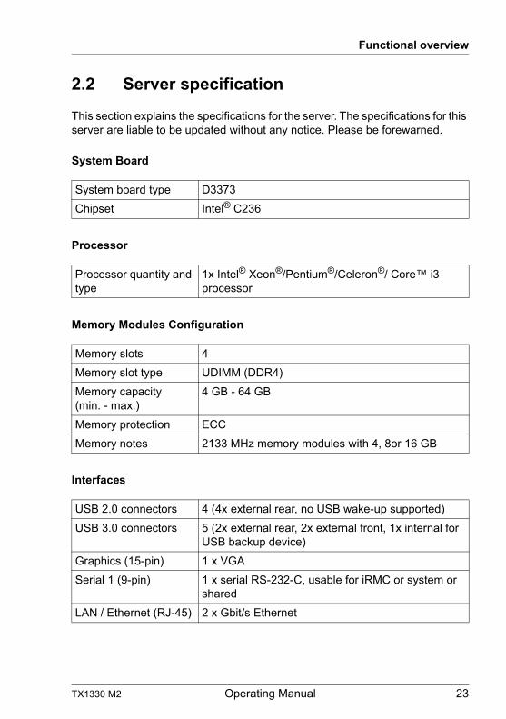
2.2 Server specification
This section explains the specifications for the server. The specifications for this server are liable to be updated without any notice. Please be forewarned.
System Board
Processor
Memory Modules Configuration
Interfaces
System board type D3373
Chipset Intel® C236
Processor quantity and type
1x Intel® Xeon®/Pentium®/Celeron®/ Core™ i3 processor
Memory slots 4
Memory slot type UDIMM (DDR4)
Memory capacity (min. - max.)
4 GB - 64 GB
Memory protection ECC
Memory notes 2133 MHz memory modules with 4, 8or 16 GB
USB 2.0 connectors 4 (4x external rear, no USB wake-up supported)
USB 3.0 connectors 5 (2x external rear, 2x external front, 1x internal for USB backup device)
Graphics (15-pin) 1 x VGA
Serial 1 (9-pin) 1 x serial RS-232-C, usable for iRMC or system or shared
LAN / Ethernet (RJ-45) 2 x Gbit/s Ethernet
24 Operating Manual TX1330 M2
Functional overview
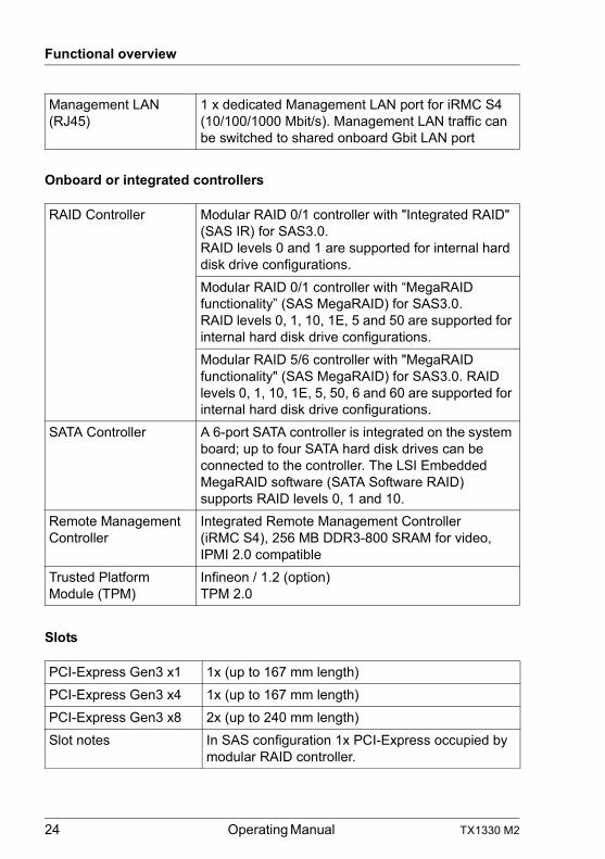
Onboard or integrated controllers
Slots
Management LAN (RJ45)
1 x dedicated Management LAN port for iRMC S4 (10/100/1000 Mbit/s). Management LAN traffic can be switched to shared onboard Gbit LAN port
RAID Controller Modular RAID 0/1 controller with "Integrated RAID" (SAS IR) for SAS3.0.RAID levels 0 and 1 are supported for internal hard disk drive configurations.
Modular RAID 0/1 controller with “MegaRAID functionality” (SAS MegaRAID) for SAS3.0.RAID levels 0, 1, 10, 1E, 5 and 50 are supported for internal hard disk drive configurations.
Modular RAID 5/6 controller with "MegaRAID functionality" (SAS MegaRAID) for SAS3.0. RAID levels 0, 1, 10, 1E, 5, 50, 6 and 60 are supported for internal hard disk drive configurations.
SATA Controller A 6-port SATA controller is integrated on the system board; up to four SATA hard disk drives can be connected to the controller. The LSI Embedded MegaRAID software (SATA Software RAID) supports RAID levels 0, 1 and 10.
Remote Management Controller
Integrated Remote Management Controller (iRMC S4), 256 MB DDR3-800 SRAM for video, IPMI 2.0 compatible
Trusted Platform Module (TPM)
Infineon / 1.2 (option)TPM 2.0
PCI-Express Gen3 x1 1x (up to 167 mm length)
PCI-Express Gen3 x4 1x (up to 167 mm length)
PCI-Express Gen3 x8 2x (up to 240 mm length)
Slot notes In SAS configuration 1x PCI-Express occupied by modular RAID controller.
TX1330 M2 Operating Manual 25
Functional overview
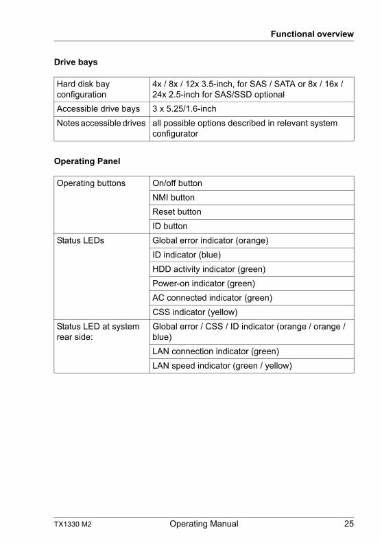
Drive bays
Operating Panel
Hard disk bay configuration
4x / 8x / 12x 3.5-inch, for SAS / SATA or 8x / 16x / 24x 2.5-inch for SAS/SSD optional
Accessible drive bays 3 x 5.25/1.6-inch
Notes accessible drives all possible options described in relevant system configurator
Operating buttons On/off button
NMI button
Reset button
ID button
Status LEDs Global error indicator (orange)
ID indicator (blue)
HDD activity indicator (green)
Power-on indicator (green)
AC connected indicator (green)
CSS indicator (yellow)
Status LED at system rear side:
Global error / CSS / ID indicator (orange / orange / blue)
LAN connection indicator (green)
LAN speed indicator (green / yellow)
26 Operating Manual TX1330 M2
Functional overview
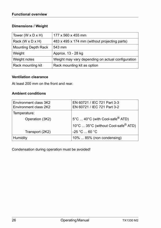
Dimensions / Weight
Ventilation clearance
At least 200 mm on the front and rear.
Ambient conditions
Condensation during operation must be avoided!
Tower (W x D x H) 177 x 560 x 455 mm
Rack (W x D x H) 483 x 495 x 174 mm (without projecting parts)
Mounting Depth Rack 543 mm
Weight Approx. 13 - 28 kg
Weight notes Weight may vary depending on actual configuration
Rack mounting kit Rack mounting kit as option
Environment class 3K2Environment class 2K2
EN 60721 / IEC 721 Part 3-3EN 60721 / IEC 721 Part 3-2
Temperature:
Operation (3K2) 5°C ... 40°C (with Cool-safe® ATD)
10°C ... 35°C (without Cool-safe® ATD)
Transport (2K2) -25 °C ... 60 °C
Humidity 10% ... 85% (non condensing)
TX1330 M2 Operating Manual 27
Functional overview
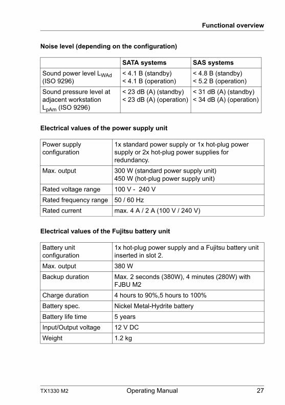
Noise level (depending on the configuration)
Electrical values of the power supply unit
Electrical values of the Fujitsu battery unit
SATA systems SAS systems
Sound power level LWAd (ISO 9296)
< 4.1 B (standby)< 4.1 B (operation)
< 4.8 B (standby)< 5.2 B (operation)
Sound pressure level at adjacent workstationLpAm (ISO 9296)
< 23 dB (A) (standby)< 23 dB (A) (operation)
< 31 dB (A) (standby)< 34 dB (A) (operation)
Power supply configuration
1x standard power supply or 1x hot-plug power supply or 2x hot-plug power supplies for redundancy.
Max. output 300 W (standard power supply unit)450 W (hot-plug power supply unit)
Rated voltage range 100 V - 240 V
Rated frequency range 50 / 60 Hz
Rated current max. 4 A / 2 A (100 V / 240 V)
Battery unit configuration
1x hot-plug power supply and a Fujitsu battery unit inserted in slot 2.
Max. output 380 W
Backup duration Max. 2 seconds (380W), 4 minutes (280W) with FJBU M2
Charge duration 4 hours to 90%,5 hours to 100%
Battery spec. Nickel Metal-Hydrite battery
Battery life time 5 years
Input/Output voltage 12 V DC
Weight 1.2 kg
28 Operating Manual TX1330 M2
Functional overview
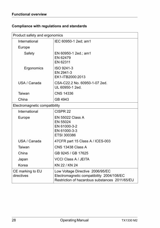
Compliance with regulations and standards
Product safety and ergonomics
International IEC 60950-1 2ed; am1
Europe
Safety EN 60950-1 2ed.; am1EN 62479EN 62311
Ergonomics ISO 9241-3EN 2941-3EK1-ITB2000:2013
USA / Canada CSA-C22.2 No. 60950-1-07 2ed.UL 60950-1 2ed.
Taiwan CNS 14336
China GB 4943
Electromagnetic compatibility
International CISPR 22
Europe EN 55022 Class AEN 55024EN 61000-3-2EN 61000-3-3ETSI 300386
USA / Canada 47CFR part 15 Class A / ICES-003
Taiwan CNS 13438 Class A
China GB 9245 / GB 17625
Japan VCCI Class A / JEITA
Korea KN 22 / KN 24
CE marking to EU directives
Low Voltage Directive 2006/95/ECElectromagnetic compatibility 2004/108/ECRestriction of hazardous substances 2011/65/EU
TX1330 M2 Operating Manual 29
3 Installation steps, overview
This chapter contains an overview of the steps necessary to install your server. Links take you to sections where you can find more detailed information about the respective steps:
Ê First of all, it is essential that you familiarize yourself with the safety information in chapter "Important information" on page 31.
Ê Transport the server to the place where you want to set it up.
Ê Unpack all parts, check the contents of the package for visible transport damage and check whether the items delivered match the details on the delivery note (see section "Unpacking the server" on page 46).
Ê Make sure that all necessary manuals (see "Documentation overview" on page 10) are available; print out the PDF files if required.
Ê Components that have been ordered additionally may be delivered loose with the server. Install these in the server as described in the supplied documentation.
Ê Set up the floorstand model (see section "Setting up the floorstand model" on page 47) or install the rack model in the rack (see section "Installing/removing the rack model" on page 48).
Ê Wire the server. Follow the instructions in sections "Connecting devices to the server" on page 50 and "Notes on connecting/disconnecting cables" on page 54.
Ê Connect the server to the mains (see section "Connecting the server to the mains" on page 51).
Ê Familiarize yourself with the controls and indicators on the front and rear of the server (see section "Control elements and indicators" on page 60).
Ê Configure the server and install the desired operating system and applications. The following options are available:
– Remote installation with the ServerView Installation Manager:
With the ServerView Suite DVD provided, you can configure the server and install the operating system in a convenient manner.
30 Operating Manual TX1330 M2
Installation steps, overview
Details on how to operate the ServerView Installation Manager, as well as some additional information, are included in the "ServerView Suite Installation Manager" user’s guide (on the Fujitsu manuals server under x86 Servers - Software - ServerView Suite - Server Installation and Deployment).
Configuration information can also be found in section "Configuring the server and installing the operating system with the ServerView Installation Manager" on page 75.
– Local configuration and installation with or without the ServerView Installation Manager (see section "Configuring the server and installing the operating system with the ServerView Installation Manager" on page 75 or section "Configuring the server and installing the operating system without the ServerView Installation Manager" on page 76).
I You will find more information on installing the server remotely or locally in the "ServerView Suite Installation Manager" user’s guide (on the Fujitsu manuals server under x86 Servers - Software - ServerView Suite - Server Installation and Deployment).
TX1330 M2 Operating Manual 31
4 Important information
In this chapter you will find essential information regarding safety when working on your server.
4.1 Safety instructions
I The following safety instructions are also provided in the manual "Safety Notes and Regulations" or " 安全上のご注意 ".
This device meets the relevant safety regulations for IT equipment. If you have any questions about whether you can install the server in the intended environment, please contact your sales outlet or our customer service team.
V CAUTION!
● The actions described in this manual shall be performed by technical specialists. A technical specialist is a person who is trained to install the server including hardware and software.
● Repairs to the device that do not relate to CSS failures shall be performed by service personnel. Please note that unauthorized interference with the system will void the warranty and exempt the manufacturer from all liability.
● Any failure to observe the guidelines in this manual, and any improper repairs could expose the user to risks (electric shock, energy hazards, fire hazards) or damage the equipment.
● Before installing/removing internal options to/from the server, turn off the server, all peripheral devices, and any other connected devices. Also unplug all power cords from the power outlet. Failure to do so can cause electric shock.
32 Operating Manual TX1330 M2
Important information
Before starting up
V CAUTION!
● During installation and before operating the device, observe the instructions on environmental conditions for your device (see "Ambient conditions" on page 26).
● If the server has been moved from a cold environment, condensation may form both inside and on the outside of the machine.
Wait until the server has acclimatized to room temperature and is absolutely dry before starting it up. Material damage may be caused to the server if this requirement is not met.
● Only transport the server in the original packaging or in packaging that protects it from impacts and jolts.
Installation and operation
V CAUTION!
● This unit should not be operated in ambient temperatures above 35 °C. For servers with Cool-safe® Advanced Thermal Design the ambient temperature can increase to 40 °C.
● If the unit is integrated into an installation that draws power from an industrial power supply network with an IEC309 connector, the power supply's fuse protection must comply with the requirements for non-industrial power supply networks for type A connectors.
● The unit automatically adjusts itself to a mains voltage in a range of 100 V - 240 V. Ensure that the local mains voltage lies within these limits.
● This device must only be connected to properly grounded power outlets or insulated sockets of the rack's internal power supply with tested and approved power cords.
● Ensure that the device is connected to a properly grounded power outlet close to the device.
TX1330 M2 Operating Manual 33
Important information
V CAUTION!
● Ensure that the power sockets on the device and the properly grounded power outlets are freely accessible.
● The On/Off button or the main power switch (if present) does not isolate the device from the mains power supply. To disconnect it completely from the mains power supply, unplug all network power plugs from the properly grounded power outlets.
● Always connect the server and the attached peripherals to the same power circuit. Otherwise you run the risk of losing data if, for example, the server is still running but a peripheral device (e.g. memory subsystem) fails during a power outage.
● Data cables must be adequately shielded.
● Ethernet cabling has to comply with EN 50173 and EN 50174-1/2 standards or ISO/IEC 11801 standard respectively. The minimum requirement is a Category 5 shielded cable for 10/100 Ethernet, or a Category 5e cable for Gigabit Ethernet.
● Route the cables in such a way that they do not create a potential hazard (make sure no-one can trip over them) and that they cannot be damaged. When connecting the server, refer to the relevant instructions in this manual.
● Never connect or disconnect data transmission lines during a storm (risk of lightning hazard).
● Make sure that no objects (e.g. jewelry, paperclips etc.) or liquids can get inside the server (risk of electric shock, short circuit).
● In emergencies (e.g. damaged casing, controls or cables, penetration of liquids or foreign bodies), switch off the server immediately, remove all power plugs and contact your sales outlet or customer service team.
34 Operating Manual TX1330 M2
Important information
V CAUTION!
● Proper operation of the system (in accordance with IEC 60950-1/2 resp. EN 60950-1/2) is only ensured if the casing is completely assembled and the rear covers for the installation slots have been fitted (electric shock, cooling, fire protection, interference suppression).
● Only install system expansions that satisfy the requirements and rules governing safety and electromagnetic compatibility and those relating to telecommunication terminals. If you install other expansions, they may damage the system or violate the safety regulations. Information on which system expansions are approved for installation can be obtained from our customer service center or your sales outlet.
● The components marked with a warning notice (e.g. lightning symbol) may only be opened, removed or exchanged by authorized, qualified personnel. Exception: CSS components can be replaced.
● The warranty is void if the server is damaged during installation or replacement of system expansions.
● Only set screen resolutions and refresh rates that are specified in the operating manual for the monitor. Otherwise, you may damage your monitor. If you are in any doubt, contact your sales outlet or customer service center.
● Before installing/removing internal options to/from the server, turn off the server, all peripheral devices, and any other connected devices. Also unplug all power cords from the outlet. Failure to do so can cause electric shock.
● Do not damage or modify internal cables or devices. Doing so may cause a device failure, fire, or electric shock.
● Devices inside the server remain hot after shutdown. Wait for a while after shutdown before installing or removing internal options.
● The circuit boards and soldered parts of internal options are exposed and can be damaged by static electricity. Before handling them, first touch a metal part of the server to discharge static electricity from your body.
● Do not touch the circuitry on boards or soldered parts. Hold the metallic areas or the edges of the circuit boards.
TX1330 M2 Operating Manual 35
Important information
V CAUTION!
● Install the screw removed during installation/detaching Internal Options in former device/position. To use a screw of the different kind causes a breakdown of equipment.
● The installation indicated on this note is sometimes changed to the kind of possible options without notice.
Batteries
V CAUTION!
● Incorrect replacement of batteries may lead to a risk of explosion. The batteries may only be replaced with identical batteries or with a type recommended by the manufacturer (refer to the "FUJITSU Server PRIMERGY TX1330 M2 Upgrade and Maintenance Manual").
● Do not throw batteries into the trash can.
● Batteries must be disposed of in accordance with local regulations concerning special waste.
● Replace the lithium battery on the system board in accordance with the instructions in the "FUJITSU Server PRIMERGY TX1330 M2 Upgrade and Maintenance Manual".
● All batteries containing pollutants are marked with a symbol (a crossed-out garbage can). In addition, the marking is provided with the chemical symbol of the heavy metal decisive for the classification as a pollutant:
Cd Cadmium Hg Mercury Pb Lead
36 Operating Manual TX1330 M2
Important information
Working with CDs/DVDs/BDs and optical drives
When working with devices with optical drives, these instructions must be followed.
V CAUTION!
● Only use CDs/DVDs/BDs that are in perfect condition, in order to prevent data loss, equipment damage and injury.
● Check each CD/DVD/BD for damage, cracks, breakages etc. before inserting it in the drive.
Note that any additional labels applied may change the mechanical properties of a CD/DVD/BD and cause imbalance.
Damaged and imbalanced CDs/DVDs/BDs can break at high drive speeds (data loss).
Under certain circumstances, sharp CD/DVD/BD fragments can pierce the cover of the optical drive (equipment damage) and can fly out of the device (danger of injury, particularly to uncovered body parts such as the face or neck).
● High humidity and airborne dust levels are to be avoided. Electric shocks and/or server failures may be caused by liquids such as water, or metallic items, such as paper clips, entering a drive.
● Shocks and vibrations are also to be avoided.
● Do not insert any objects other than the specified CDs/DVDs/BDs.
● Do not pull on, press hard, or otherwise handle the CD/DVD/BD tray roughly.
● Do not disassemble the optical drive.
● Before use, clean the optical disk tray using a soft, dry cloth.
● As a precaution, remove disks from the optical drive when the drive is not to be used for a long time. Keep the optical disk tray closed to prevent foreign matter, such as dust, from entering the optical drive.
● Hold CDs/DVDs/BDs by their edges to avoid contact with the disk surface.
TX1330 M2 Operating Manual 37
Important information
● Do not contaminate the CD/DVD/BD surface with fingerprints, oil, dust, etc. If dirty, clean with a soft, dry cloth, wiping from the center to the edge. Do not use benzene, thinners, water, record sprays, antistatic agents, or silicone-impregnated cloth.
● Be careful not to damage the CD/DVD/BD surface.
● Keep the CDs/DVDs/BDs away from heat sources.
● Do not bend or place heavy objects on CDs/DVDs/BDs.
● Do not write with ballpoint pen or pencil on the label (printed) side.
● Do not attach stickers or similar to the label side. Doing so may cause rotational eccentricity and abnormal vibrations.
● When a CD/DVD/BD is moved from a cold place to a warm place, moisture condensation on the CD/DVD/BD surface can cause data read errors. In this case, wipe the CD/DVD/BD with a soft, dry cloth then let it air dry. Do not dry the CD/DVD/BD using devices such as a hair dryer.
● To avoid dust, damage, and deformation, keep the CD/DVD/BD in its case whenever it is not in use.
● Do not store CDs/DVDs/BDs at high temperatures. Areas exposed to prolonged direct sunlight or near heating appliances are to be avoided.
I You can prevent damage from the optical drive and the CDs/DVDs/BDs, as well as premature wear of the disks, by observing the following suggestions:
– Only insert disks in the drive when needed and remove them after use.
– Store the disks in suitable sleeves.– Protect the disks from exposure to heat and direct sunlight.
Laser information
The optical drive complies with IEC 60825-1 laser class 1.
V CAUTION!
The optical drive contains a light-emitting diode (LED), which under certain circumstances produces a laser beam stronger than laser class 1. Looking directly at this beam is dangerous.
Never remove parts of the optical drive casing!
38 Operating Manual TX1330 M2
Important information
Modules with Electrostatic-Sensitive Devices
Modules with electrostatic-sensitive devices are identified by the following sticker:
Figure 1: ESD label
When you handle components fitted with ESDs, you must always observe the following points:
● Switch off the system and remove the power plugs from the power outlets before installing or removing components with ESDs.
● You must always discharge static build-up (e.g. by touching a grounded object) before working with such components.
● Any devices or tools that are used must be free of electrostatic charge.
● Wear a suitable grounding cable that connects you to the external chassis of the system unit.
● Always hold components with ESDs at the edges or at the points marked green (touch points).
● Do not touch any connectors or conduction paths on an ESD.
● Place all the components on a pad which is free of electrostatic charge.
I For a detailed description of how to handle ESD components, see the relevant European or international standards (EN 61340-5-1, ANSI/ESD S20.20).
Information for ensuring electromagnetic compatibility
All data and signal cables must have sufficient shielding. The use of cable type S/FTP Cat5 or higher is recommended. Use of unshielded or badly shielded cables may lead to increased emission of interference and/or reduced fault-tolerance of the device.
TX1330 M2 Operating Manual 39
Important information
Other important information:
● During cleaning, observe the instructions in section "Cleaning the server" on page 77.
● Keep this operating manual and the other documentation (such as the technical manual, documentation DVD) close to the device. All documentation must be included if the equipment is passed on to a third party.
4.2 ENERGY STAR
4.3 CE conformity
Products that have been certified compliant with ENERGY STAR and identified as such are in full compliance with the specification at shipping. Note that energy consumption can be affected by software that is installed or any changes that are made to the hardware configuration or BIOS or energy options subsequently. In such cases, the properties guaranteed by ENERGY STAR can no longer be assured.
The "ServerView Operations Manager" user guide contains instructions for reading out measurement values, including those relating to current energy consumption and air temperatures. Either the Performance Monitor or the Task Manager can be used to read out CPU utilization levels.
The system complies with the requirements of the EC directives 2004/108/EC regarding "Electromagnetic Compatibility" and 2006/95/EC "Low Voltage Directive" and the directive of the European Parliament and Council 2011/65/EU. This is indicated by the CE marking (CE = Communauté Européenne).
40 Operating Manual TX1330 M2
Important information
4.4 FCC Class A Compliance Statement
If there is an FCC statement on the device, it applies to the products covered in this manual, unless otherwise specified herein. The statement for other products will appear in the accompanying documentation.
NOTE:
This equipment has been tested and found to comply with the limits for a "Class A" digital device, pursuant to Part 15 of the FCC rules and meets all requirements of the Canadian Interference-Causing Equipment Standard ICES-003 for digital apparatus. These limits are designed to provide reasonable protection against harmful interference in a residential installation. This equipment generates, uses and can radiate radio frequency energy and, if not installed and used in strict accordance with the instructions, may cause harmful interference to radio communications. However, there is no warranty that interference will not occur in a particular installation. If this equipment does cause harmful interference to radio or television reception, which can be determined by turning the equipment off and on, the user is encouraged to try to correct the interference by one or more of the following measures:
● Reorient or relocate the receiving antenna.
● Increase the separation between equipment and the receiver.
● Connect the equipment into an outlet on a circuit different from that to which the receiver is connected.
● Consult the dealer or an experienced radio/TV technician for help.
Fujitsu is not responsible for any radio or television interference caused by unauthorized modifications of this equipment or the substitution or attachment of connecting cables and equipment other than those specified by Fujitsu. The correction of interferences caused by such unauthorized modification, substitution or attachment will be the responsibility of the user.
The use of shielded I/O cables is required when connecting this equipment to any and all optional peripheral or host devices. Failure to do so may violate FCC and ICES rules.
WARNING:
This is a class A product. In a domestic environment this product may cause radio interference in which case the user may be required to take adequate measures.
TX1330 M2 Operating Manual 41
Important information
4.5 Transporting the server
V CAUTION!
Only transport the server in its original packaging or in packaging that protects it from impacts and jolts. Do not unpack the server until it is at its installation location.
If you need to lift or transport the server, ask other people to help you.
Never lift or carry the device by the Quick Release Levers (QRLs) on the front panel.
4.6 Notes on installing the server in the rack
V CAUTION!
● For safety reasons, at least two people are required to install the server in the rack because of its weight and size.
(For the Japanese market, please refer to " 安全上のご注意 ".)
● Never lift the server into the rack using the QRLs (Quick Release Levers) on the front panel.
● When connecting and disconnecting cables, observe the relevant instructions in the "Important Information" chapter of the technical manual for the corresponding rack. The technical manual is supplied with the corresponding rack.
● When installing the rack, make sure that the anti-tilt mechanism is correctly fitted.
● Do not extend more than one unit out of the rack simultaneously even if the tilt protection is in place. If several units are simultaneously extended from the rack, there is a risk that the rack could tip over. See the safety information of the rack and the warning label.
● Only for the EMEA market:The rack must be connected to the power supply by an authorized specialist (electrician).
42 Operating Manual TX1330 M2
Important information
● If the server is integrated into an installation that draws power from an industrial power supply network with an IEC309 type connector, the power supply's fuse protection must comply with the requirements for non-industrial power supply networks for the type A connector.

TX1330 M2 Operating Manual 43
Important information
4.7 Environmental protection
Environmentally-friendly product design and development
This product has been designed in accordance with the Fujitsu standard for "environmentally friendly product design and development". This means that key factors such as durability, selection and labeling of materials, emissions, packaging, ease of dismantling and recycling have been taken into account.
This saves resources and thus reduces the harm done to the environment. Further information can be found at:
– http://ts.fujitsu.com/products/standard_servers/index.html (for the global market)– http://jp.fujitsu.com/platform/server/primergy/concept/ (for the Japanese
market)
Energy-saving information
Devices that do not need to be constantly switched on should be switched off until they are needed as well as during long breaks and after completion of work.
Packaging information
This packaging information doesn’t apply to the Japanese market.
Do not throw away the packaging. You may need it later for transporting the system. If possible, the equipment should only be transported in its original packaging.
Information on handling consumables
Please dispose of printer consumables and batteries in accordance with the applicable national regulations.
In accordance with EU directives, batteries must not be disposed of with unsorted domestic waste. They can be returned free of charge to the manufacturer, dealer or an authorized agent for recycling or disposal.
All batteries containing pollutants are marked with a symbol (a crossed-out garbage can). They are also marked with the chemical symbol for the heavy metal that causes them to be categorized as containing pollutants:
Cd CadmiumHg MercuryPb Lead
44 Operating Manual TX1330 M2
Important information
Labels on plastic casing parts
Please avoid sticking your own labels on plastic parts wherever possible, since this makes it difficult to recycle them.
Returns, recycling and disposal
Please handle returns, recycling and disposal in accordance with local regulations.
Details regarding the return and recycling of devices and consumables within Europe can also be found in the "Returning used devices" manual, via your local Fujitsu branch or from our recycling center in Paderborn:
Fujitsu Technology SolutionsRecycling CenterD-33106 Paderborn
Tel. +49 5251 525 1410Fax +49 5251 525 32 1410
The device must not be disposed of with domestic waste. This device is labeled in compliance with European directive 2002/96/EC on waste electrical and electronic equipment (WEEE).
This directive sets the framework for returning and recycling used equipment and is valid across the EU. When returning your used device, please use the return and collection systems available to you. Further information can be found at http://ts.fujitsu.com/recycling.
TX1330 M2 Operating Manual 45
5 Hardware installation
V CAUTION!
● Follow the safety instructions in the chapter "Important information" on page 31.
● Do not expose the server to extreme environmental conditions (see "Ambient conditions" on page 26). Protect the server from dust, humidity and heat.
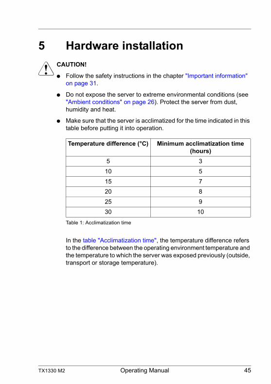
● Make sure that the server is acclimatized for the time indicated in this table before putting it into operation.
In the table "Acclimatization time", the temperature difference refers to the difference between the operating environment temperature and the temperature to which the server was exposed previously (outside, transport or storage temperature).
Temperature difference (°C) Minimum acclimatization time (hours)
5 3
10 5
15 7
20 8
25 9
30 10
Table 1: Acclimatization time
46 Operating Manual TX1330 M2
Hardware installation
5.1 Unpacking the server
V CAUTION!
Follow the safety instructions in "Important information" on page 31.
The server must always be lifted or carried by at least two people.(For the Japanese market, please refer to " 安全上のご注意 ".)
Do not unpack the server until it is at its installation location.
Ê Transport the server to the place where you want to set it up.
Ê Unpack all individual parts.
Keep the original packaging in case you want to transport the server again (applies only to global market).
Ê Check the delivery for any damage during transport.
Ê Check whether the items delivered match the details on the delivery note.
The product name and serial number of the product can be found on the ID card (see section "ID card" on page 64).
Ê Notify your supplier immediately should you discover that the items delivered do not correspond to the delivery note.
TX1330 M2 Operating Manual 47
Hardware installation
5.2 Setting up the floorstand model
I If you are not installing a PRIMERGY TX1330 M2 floorstand model, skip this section and continue reading at section "Installing/removing the rack model" on page 48.
Ê Transport the server to the place where you want to set it up.
Ê Unpack the server (see section "Unpacking the server").
Ê Set up the server.
V CAUTION!
– The device must be protected from direct sunlight.– The required minimum distances for operation and maintenance
areas must be adhered to. – The server must be accessible at the rear for connection to other
devices (e.g. memory subsystem).– The mains plug must be accessible easily and safely.– There must be a clearance of at least 200 mm in front of and
behind the server to ensure adequate ventilation of the subsystem.
Ê Wire the server. Follow the instructions in sections "Connecting devices to the server" on page 50 and "Notes on connecting/disconnecting cables" on page 54.
Ê Connect the server to the mains (see section "Connecting the server to the mains" on page 51).
48 Operating Manual TX1330 M2
Hardware installation
5.3 Installing/removing the rack model
V CAUTION!
● Please observe the safety information and notes on rack mounting in chapter "Important information" on page 31 and section "Notes on installing the server in the rack" on page 41.
● At least two people are needed to install / remove the server in the rack. (For the Japanese market, please refer to " 安全上のご注意 ".)
● Do not extend more than one unit out of the rack simultaneously even if the tilt protection is in place. If several units are simultaneously extended out of the rack, there is a risk that the rack could tip over.
Fujitsu rack systems
The rack systems from Fujitsu support the installation of PRIMERGY servers:
– PRIMECENTER rack– PRIMECENTER M1 rack– DataCenter rack– 19-inch standard rack (for the Japanese market)– 19-inch slim rack (for the Japanese market)
I For information on mounting the server in the rack please refer to the Mounting Instructions provided with the Rack Mounting Kit. Further information you find in the manual of your rack system.
For the Japanese market, please refer also to the "Rack system structure guide.
I Online documentation for rack installation can be found on:
http://manuals.ts.fujitsu.com/index.php?id=5406-5605-5606 (for the EMEA market)
http://jp.fujitsu.com/platform/server/primergy/manual/peri_rack.html (for the Japanese market).
To accommodate the ventilation concept and ensure proper ventilation, any unused areas in the rack must be sealed using dummy covers.
The power is supplied via the multiple socket outlets fitted in the rack (for the EMEA market).
TX1330 M2 Operating Manual 49
Hardware installation
The main features of Fujitsu rack systems are as follows:
– rail systems that can be mounted without tools
– support systems having a linear alignment feature to ensure that they can be adjusted to different rack depths
Asymmetrical PRIMECENTER Rack and DataCenter Rack provide an enhanced cable management in the lateral rack area.
3rd party racks
I Installation in most current rack systems from other manufacturers (3rd party racks) is also supported. For details please contact your sales representative.
50 Operating Manual TX1330 M2
Hardware installation
5.4 Connecting devices to the server
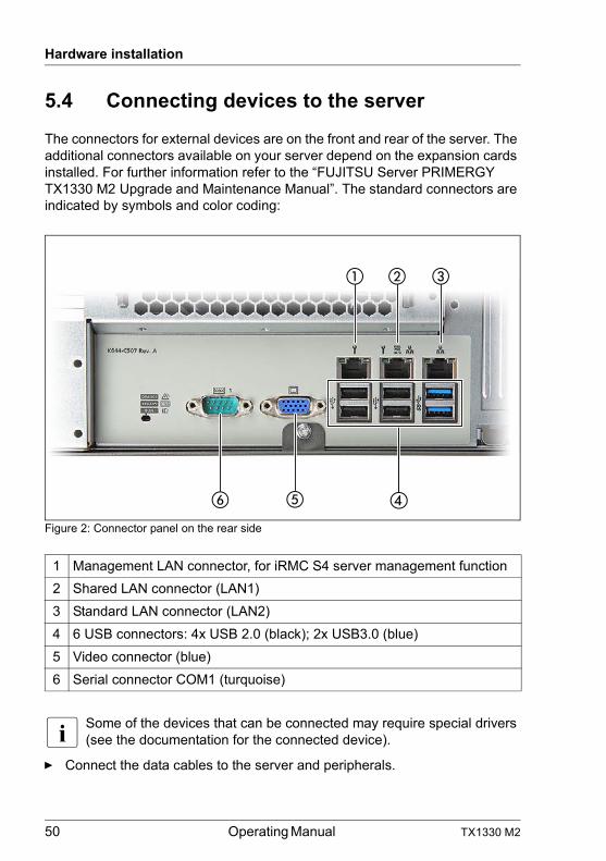
The connectors for external devices are on the front and rear of the server. The additional connectors available on your server depend on the expansion cards installed. For further information refer to the “FUJITSU Server PRIMERGY TX1330 M2 Upgrade and Maintenance Manual”. The standard connectors are indicated by symbols and color coding:
Figure 2: Connector panel on the rear side
I Some of the devices that can be connected may require special drivers (see the documentation for the connected device).
Ê Connect the data cables to the server and peripherals.
1 Management LAN connector, for iRMC S4 server management function
2 Shared LAN connector (LAN1)
3 Standard LAN connector (LAN2)
4 6 USB connectors: 4x USB 2.0 (black); 2x USB3.0 (blue)
5 Video connector (blue)
6 Serial connector COM1 (turquoise)
�� �
� ��
TX1330 M2 Operating Manual 51
Hardware installation
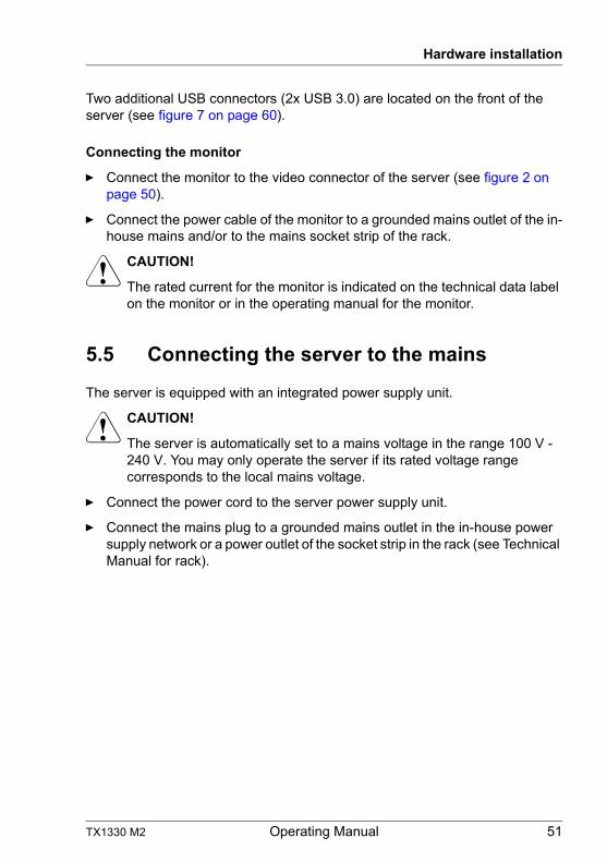
Two additional USB connectors (2x USB 3.0) are located on the front of the server (see figure 7 on page 60).
Connecting the monitor
Ê Connect the monitor to the video connector of the server (see figure 2 on page 50).
Ê Connect the power cable of the monitor to a grounded mains outlet of the in-house mains and/or to the mains socket strip of the rack.
V CAUTION!
The rated current for the monitor is indicated on the technical data label on the monitor or in the operating manual for the monitor.
5.5 Connecting the server to the mains
The server is equipped with an integrated power supply unit.
V CAUTION!
The server is automatically set to a mains voltage in the range 100 V - 240 V. You may only operate the server if its rated voltage range corresponds to the local mains voltage.
Ê Connect the power cord to the server power supply unit.
Ê Connect the mains plug to a grounded mains outlet in the in-house power supply network or a power outlet of the socket strip in the rack (see Technical Manual for rack).
52 Operating Manual TX1330 M2
Hardware installation
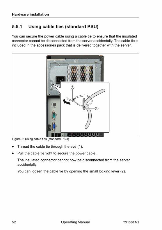
5.5.1 Using cable ties (standard PSU)
You can secure the power cable using a cable tie to ensure that the insulated connector cannot be disconnected from the server accidentally. The cable tie is included in the accessories pack that is delivered together with the server.
Figure 3: Using cable ties (standard PSU)
Ê Thread the cable tie through the eye (1).
Ê Pull the cable tie tight to secure the power cable.
The insulated connector cannot now be disconnected from the server accidentally.
You can loosen the cable tie by opening the small locking lever (2).
�
�
TX1330 M2 Operating Manual 53
Hardware installation
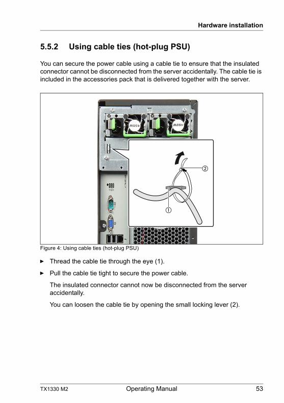
5.5.2 Using cable ties (hot-plug PSU)
You can secure the power cable using a cable tie to ensure that the insulated connector cannot be disconnected from the server accidentally. The cable tie is included in the accessories pack that is delivered together with the server.
Figure 4: Using cable ties (hot-plug PSU)
Ê Thread the cable tie through the eye (1).
Ê Pull the cable tie tight to secure the power cable.
The insulated connector cannot now be disconnected from the server accidentally.
You can loosen the cable tie by opening the small locking lever (2).
�
�
54 Operating Manual TX1330 M2
Hardware installation
5.6 Notes on connecting/disconnecting cables
V CAUTION!
Always read the documentation supplied with the device you wish to connect.
Never connect, or disconnect cables during a thunderstorm.
Never pull on a cable when disconnecting it. Always take hold of the cable by the plug.
Follow the sequence described below to connect or disconnect external devices to or from the server:
Be sure to wait for 10 seconds or more after shutdown before turning the server on.
Connecting cables
Ê Turn off all power and equipment switches.
Ê Disconnect all power plugs from the properly grounded power outlets.
Ê Connect all cables to the server and peripherals.
Ê Plug all data communication cables into the utility sockets.
Ê Plug all power cords into the properly grounded power outlets.
Disconnecting cables
Ê Turn off all power and equipment switches.
Ê Disconnect all power plugs from the properly grounded power outlets.
Ê Unplug all data communication cables from the utility sockets.
Ê Disconnect the relevant cables from the server and all the peripherals.
I For connecting or disconnecting LAN cables, the server does not need to be powered off. To avoid loss of data teaming function has to be enabled.
TX1330 M2 Operating Manual 55
Hardware installation
Information for ensuring electromagnetic compatibility
All data and signal cables must have sufficient shielding. The use of cable type S/FTP Cat5 or higher is recommended. Use of unshielded or badly shielded cables may lead to increased emission of interference and/or reduced fault-tolerance of the device.
56 Operating Manual TX1330 M2
Hardware installation
TX1330 M2 Operating Manual 57
6 Starting up and operation
V CAUTION!
Follow the safety instructions in chapter "Important information" on page 31.
6.1 Access to the drives (floorstand model)
6.1.1 Enabling access to the accessible drives
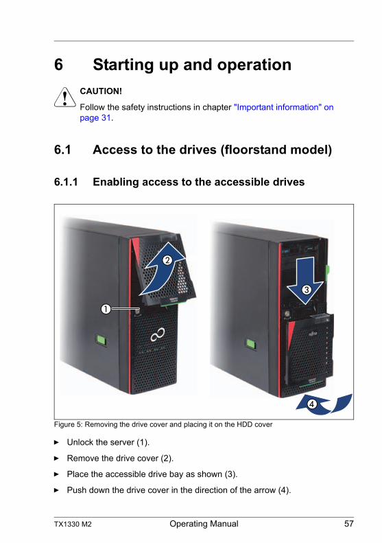
Figure 5: Removing the drive cover and placing it on the HDD cover
Ê Unlock the server (1).
Ê Remove the drive cover (2).
Ê Place the accessible drive bay as shown (3).
Ê Push down the drive cover in the direction of the arrow (4).
58 Operating Manual TX1330 M2
Starting up and operation
I Please note the following when operating with tape drives:
If the system is programmed to eject the media automatically, the accessible drives must not be obstructed.
The drive cover is replaced and the server locked in the reverse order.
TX1330 M2 Operating Manual 59
Starting up and operation
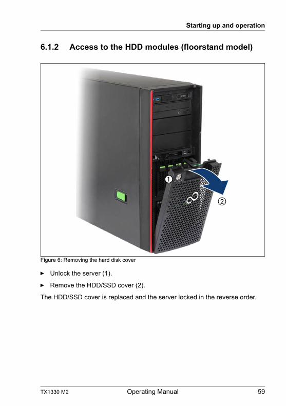
6.1.2 Access to the HDD modules (floorstand model)
Figure 6: Removing the hard disk cover
Ê Unlock the server (1).
Ê Remove the HDD/SSD cover (2).
The HDD/SSD cover is replaced and the server locked in the reverse order.
60 Operating Manual TX1330 M2
Starting up and operation
6.2 Control elements and indicators
6.2.1 Front of the server
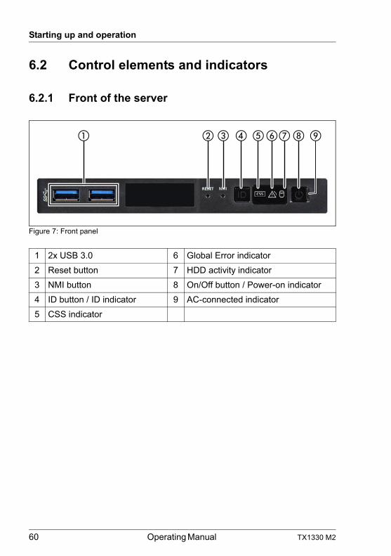
Figure 7: Front panel
1 2x USB 3.0 6 Global Error indicator
2 Reset button 7 HDD activity indicator
3 NMI button 8 On/Off button / Power-on indicator
4 ID button / ID indicator 9 AC-connected indicator
5 CSS indicator
TX1330 M2 Operating Manual 61
Starting up and operation
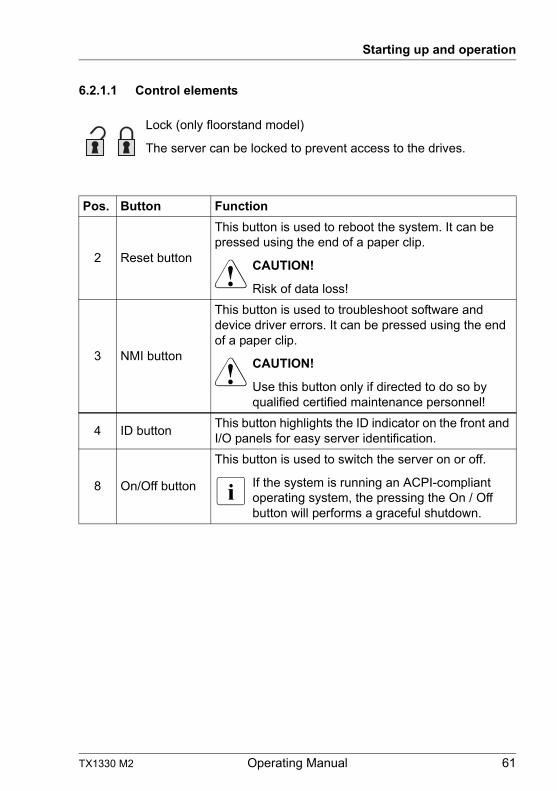
6.2.1.1 Control elements
Lock (only floorstand model)
The server can be locked to prevent access to the drives.
Pos. Button Function
2 Reset button
This button is used to reboot the system. It can be pressed using the end of a paper clip.
V CAUTION!
Risk of data loss!
3 NMI button
This button is used to troubleshoot software and device driver errors. It can be pressed using the end of a paper clip.
V CAUTION!
Use this button only if directed to do so by qualified certified maintenance personnel!
4 ID buttonThis button highlights the ID indicator on the front and I/O panels for easy server identification.
8 On/Off button
This button is used to switch the server on or off.
I If the system is running an ACPI-compliant operating system, the pressing the On / Off button will performs a graceful shutdown.
62 Operating Manual TX1330 M2
Starting up and operation
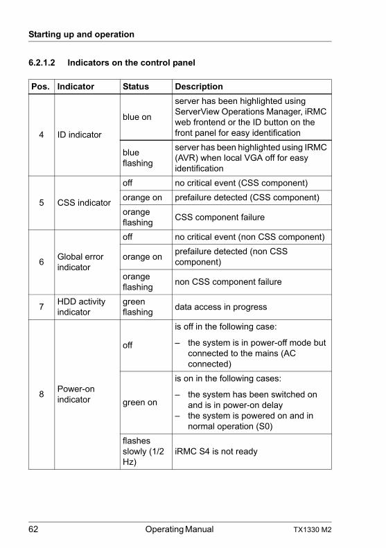
6.2.1.2 Indicators on the control panel
Pos. Indicator Status Description
4 ID indicator
blue on
server has been highlighted using ServerView Operations Manager, iRMC web frontend or the ID button on the front panel for easy identification
blue flashing
server has been highlighted using IRMC (AVR) when local VGA off for easy identification
5 CSS indicator
off no critical event (CSS component)
orange on prefailure detected (CSS component)
orange flashing
CSS component failure
6Global error indicator
off no critical event (non CSS component)
orange onprefailure detected (non CSS component)
orange flashing
non CSS component failure
7HDD activity indicator
green flashing
data access in progress
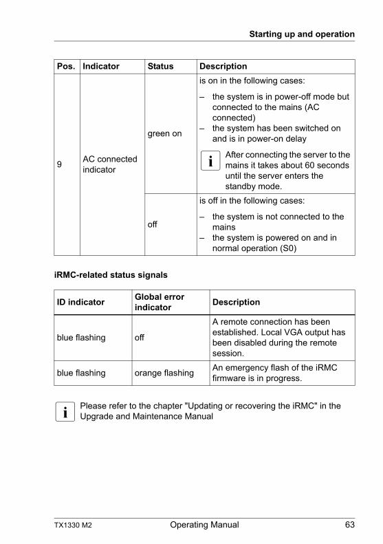
8Power-on indicator
off
is off in the following case:
– the system is in power-off mode but connected to the mains (AC connected)
green on
is on in the following cases:
– the system has been switched on and is in power-on delay
– the system is powered on and in normal operation (S0)
flashes slowly (1/2 Hz)
iRMC S4 is not ready
TX1330 M2 Operating Manual 63
Starting up and operation
iRMC-related status signals
I Please refer to the chapter "Updating or recovering the iRMC" in the Upgrade and Maintenance Manual
9AC connected indicator
green on
is on in the following cases:
– the system is in power-off mode but connected to the mains (AC connected)
– the system has been switched on and is in power-on delay
I After connecting the server to the mains it takes about 60 seconds until the server enters the standby mode.
off
is off in the following cases:
– the system is not connected to the mains
– the system is powered on and in normal operation (S0)
ID indicatorGlobal error indicator
Description
blue flashing off
A remote connection has been established. Local VGA output has been disabled during the remote session.
blue flashing orange flashingAn emergency flash of the iRMC firmware is in progress.
Pos. Indicator Status Description
64 Operating Manual TX1330 M2
Starting up and operation
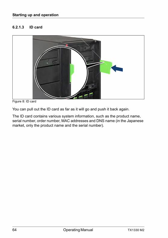
6.2.1.3 ID card
Figure 8: ID card
You can pull out the ID card as far as it will go and push it back again.
The ID card contains various system information, such as the product name, serial number, order number, MAC addresses and DNS name (in the Japanese market, only the product name and the serial number).
TX1330 M2 Operating Manual 65
Starting up and operation
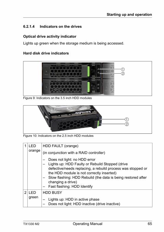
6.2.1.4 Indicators on the drives
Optical drive activity indicator
Lights up green when the storage medium is being accessed.
Hard disk drive indicators
Figure 9: Indicators on the 3.5 inch HDD modules
Figure 10: Indicators on the 2.5 inch HDD modules
1 LED orange
HDD FAULT (orange)
(in conjunction with a RAID controller)
– Does not light: no HDD error– Lights up: HDD Faulty or Rebuild Stopped (drive
defective/needs replacing, a rebuild process was stopped or the HDD module is not correctly inserted)
– Slow flashing: HDD Rebuild (the data is being restored after changing a drive)
– Fast flashing: HDD Identify
2 LED green
HDD BUSY
– Lights up: HDD in active phase– Does not light: HDD inactive (drive inactive)
��
��
66 Operating Manual TX1330 M2
Starting up and operation
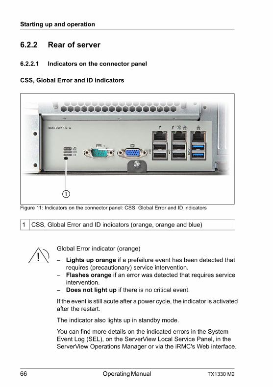
6.2.2 Rear of server
6.2.2.1 Indicators on the connector panel
CSS, Global Error and ID indicators
Figure 11: Indicators on the connector panel: CSS, Global Error and ID indicators
1 CSS, Global Error and ID indicators (orange, orange and blue)
Global Error indicator (orange)
– Lights up orange if a prefailure event has been detected that requires (precautionary) service intervention.
– Flashes orange if an error was detected that requires service intervention.
– Does not light up if there is no critical event.
If the event is still acute after a power cycle, the indicator is activated after the restart.
The indicator also lights up in standby mode.
You can find more details on the indicated errors in the System Event Log (SEL), on the ServerView Local Service Panel, in the ServerView Operations Manager or via the iRMC's Web interface.
�
!
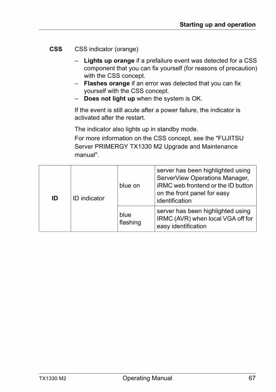
TX1330 M2 Operating Manual 67
Starting up and operation
CSS CSS indicator (orange)
– Lights up orange if a prefailure event was detected for a CSS component that you can fix yourself (for reasons of precaution) with the CSS concept.
– Flashes orange if an error was detected that you can fix yourself with the CSS concept.
– Does not light up when the system is OK.
If the event is still acute after a power failure, the indicator is activated after the restart.
The indicator also lights up in standby mode.
For more information on the CSS concept, see the "FUJITSU Server PRIMERGY TX1330 M2 Upgrade and Maintenance manual".
ID ID indicator
blue on
server has been highlighted using ServerView Operations Manager, iRMC web frontend or the ID button on the front panel for easy identification
blue flashing
server has been highlighted using IRMC (AVR) when local VGA off for easy identification
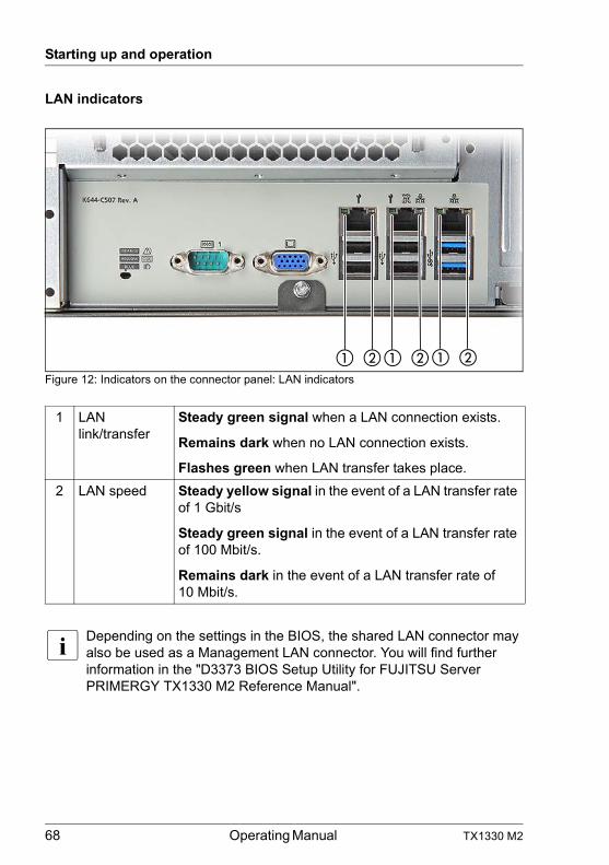
68 Operating Manual TX1330 M2
Starting up and operation
LAN indicators
Figure 12: Indicators on the connector panel: LAN indicators
I Depending on the settings in the BIOS, the shared LAN connector may also be used as a Management LAN connector. You will find further information in the "D3373 BIOS Setup Utility for FUJITSU Server PRIMERGY TX1330 M2 Reference Manual".
1 LAN link/transfer
Steady green signal when a LAN connection exists.
Remains dark when no LAN connection exists.
Flashes green when LAN transfer takes place.
2 LAN speed Steady yellow signal in the event of a LAN transfer rate of 1 Gbit/s
Steady green signal in the event of a LAN transfer rate of 100 Mbit/s.
Remains dark in the event of a LAN transfer rate of 10 Mbit/s.
� �� � � �
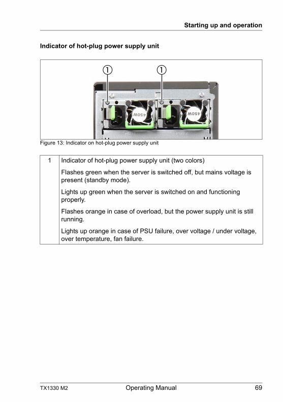
TX1330 M2 Operating Manual 69
Starting up and operation
Indicator of hot-plug power supply unit
Figure 13: Indicator on hot-plug power supply unit
1 Indicator of hot-plug power supply unit (two colors)
Flashes green when the server is switched off, but mains voltage is present (standby mode).
Lights up green when the server is switched on and functioning properly.
Flashes orange in case of overload, but the power supply unit is still running.
Lights up orange in case of PSU failure, over voltage / under voltage, over temperature, fan failure.
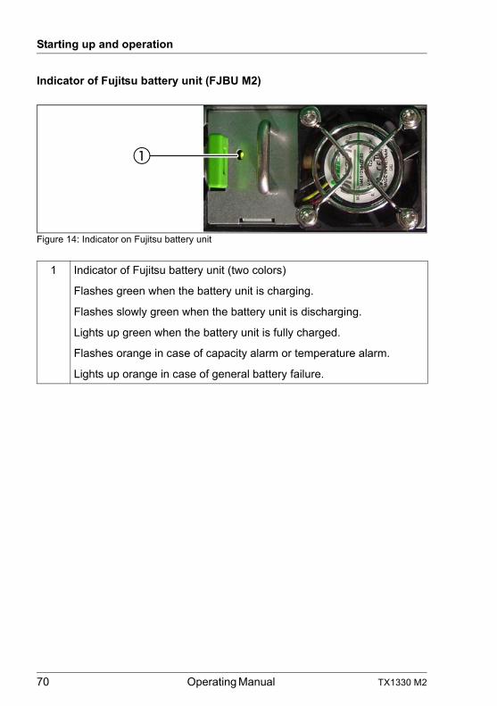
70 Operating Manual TX1330 M2
Starting up and operation
Indicator of Fujitsu battery unit (FJBU M2)
Figure 14: Indicator on Fujitsu battery unit
1 Indicator of Fujitsu battery unit (two colors)
Flashes green when the battery unit is charging.
Flashes slowly green when the battery unit is discharging.
Lights up green when the battery unit is fully charged.
Flashes orange in case of capacity alarm or temperature alarm.
Lights up orange in case of general battery failure.
TX1330 M2 Operating Manual 71
Starting up and operation
6.3 Switching the server on and off
V CAUTION!
● It nothing appears on the screen but flickering stripes after switching on the server, switch the server off immediately (see chapter "Flickering stripes on monitor screen" on page 83).
● The On/Off button does not disconnect the server from the mains voltage. To completely disconnect it from the mains voltage, remove the power plug(s) from the socket(s).
● Do not move, strike, or shake the server when it is turned on. This can damage the hard disk in the server and cause data loss.
● Turn the server on when the temperature is in its operating environment range (10–35°C). For details on the operating environment, refer to "Safety Precautions".When operating the device outside of this operating environment, the server may operate improperly, damage data etc.Furthermore, Fujitsu cannot be held responsible for any related damage, malfunction, or loss of data, etc.
● Be sure to wait for 10 seconds or more after shutdown before turning the server on.
● After connecting power cable, press a power supply button after it passes for more than 10 seconds.
Switching the server on
The power-on indicator (item 11 in figure 7 on page 60) lights up orange (standby mode) when the server is connected to the mains.
I It takes about 60 seconds until power-on becomes possible.
– Starting up for the first time:
For the Japanese market, please refer to " はじめにお読みください ".
Ê Press the On/Off button (see item 12 in figure 7 on page 60).
Ê Insert ServerView Suite DVD in the DVD drive.
72 Operating Manual TX1330 M2
Starting up and operation
Ê Follow the on-screen instructions (see also section "Configuring the server and installing the operating system with the ServerView Installation Manager" on page 75 or section "Configuring the server and installing the operating system without the ServerView Installation Manager" on page 76).
– System already installed:
Ê Press the On/Off button (see item 12 in figure 7 on page 60).
The server is switched on, performs a system test and boots the operating system.
Switching the server off
The power-on indicator lights up green (see item 11 in figure 7 on page 60).
Ê Shut down the operating system properly.
The server is switched off automatically and goes into standby mode. The power-on indicator lights up orange.
I If the operating system does not switch the server off automatically, press the On/Off button for at least four seconds and/or send a corresponding control signal.
Other On/Off options
Besides the On/Off button, the server can be switched ON and OFF in the following ways:
– Timer-controlled switch-on/off
Using the ServerView Operations Manager or iRMC, you can configure that the server is switched on/off controlled by timer.
– Ring indicator
The server is switched on by an internal or external modem.
– Wake up On LAN (WOL)
The server is switched on by a command via the LAN (Magic PacketTM).
– After power failure
The server automatically reboots following a power failure (depending on the settings in the BIOS or in iRMC).
TX1330 M2 Operating Manual 73
Starting up and operation
– Power button override
The system can be switched off by pressing and holding down the On/Off button (for approximately 4 - 5 seconds).
V CAUTION!
There is a risk that data may be lost.
– iRMC S4
iRMC S4 offers various options for switching the server on and off, e.g. via the Power On Off page of the iRMC S4 Web interface.
6.4 Configuring the server
This section contains information about configuring the server and installing the operating system.
I Make sure that the power saving functions are disabled in the Power menu of the BIOS Setup during operation.
6.4.1 Configuring the onboard SATA controller
A SATA controller is integrated on the system board. You can configure the onboard controller either before or during installation with the ServerView Installation Manager. Using the ServerView Installation Manager is recommended.
I The controller has its own configuration utility. For further information, refer to the “Embedded MegaRAID Software User’s Guide” (on the Fujitsu manuals server under x86 Servers - Expansion Cards - Storage Adapters - LSI Configuration Software - Embedded MegaRAID Software).
I Descriptions of operating systems not covered in the controller manual are provided in the corresponding readme under:
http://www.fujitsu.com/global/services/computing/server/ia/driver/index.html (for the EMEA market).
http://jp.fujitsu.com/platform/server/primergy/downloads/(for the Japanese market).
74 Operating Manual TX1330 M2
Starting up and operation
6.4.2 Configuring the SAS/SATA RAID controller (PCIe expansion card)
The server has a SAS/SATA RAID controller with "MegaRAID functionality". You can configure the SAS/SATA RAID controller either before or during installation with the ServerView Installation Manager. Using the ServerView Installation Manager is recommended.
I A separate utility is available to the controller for MegaRAID configuration. For further information, refer to the "LSI MegaRAID SAS Software User Guide" (on the Fujitsu manuals server under x86 Servers - Expansion Cards - Storage Adapters - LSI Configuration Software).
Further information on modular RAID controllers is provided in the "Modular RAID Controller Installation Guide" (on the Fujitsu manuals server under x86 Servers - Expansion Cards - Storage Adapters - LSI SAS / SCSI RAID Controllers).
I Descriptions of operating systems not covered in the controller manual are provided in the corresponding readme under:
http://www.fujitsu.com/global/services/computing/server/ia/driver/index.html (for the global market).
http://jp.fujitsu.com/platform/server/primergy/downloads/(for the Japanese market).
TX1330 M2 Operating Manual 75
Starting up and operation
6.4.3 Configuring the server and installing the operating system with the ServerView Installation Manager
Using the ServerView Installation Manager on the ServerView Suite DVD provided, you can conveniently configure the server and install the operating system. This includes configuring the server-specific settings using the ServerView Configuration Manager and configuring the RAID controller using the ServerView RAID Manager.
Advantages of the ServerView Installation Manager
– Wizard assisted configuration of your server hardware and disk arrays
– Wizard assisted installation of all leading server operating systems
– Wizard-assisted creation of configuration files for unattended installation of several PRIMERGY servers with identical hardware configurations.
– Installation of drivers and additional software.
I The software that can be installed depends on your server’s hardware configuration. This configuration is detected automatically.
I Descriptions of operating systems not covered in the RAID controller manual are provided in the corresponding readme files under:
http://www.fujitsu.com/global/services/computing/server/ia/driver/index.html (for the global market).
http://jp.fujitsu.com/platform/server/primergy/downloads/(for the Japanese market).
To find out how to operate the ServerView Installation Manager and for further information, refer to the associated manual.
If you are using the ServerView Installation Manager, you can skip the following section on how to configure the server and install the operating system. Continue from section "Cleaning the server" on page 77.
76 Operating Manual TX1330 M2
Starting up and operation
6.4.4 Configuring the server and installing the operating system without the ServerView Installation Manager
Configure onboard SATA controller
Configure the controller as described in section "Configuring the onboard SATA controller" on page 73.
Configure SAS/SATA RAID controller with "MegaRAID functionality"
Configure the controller as described in section "Configuring the SAS/SATA RAID controller (PCIe expansion card)" on page 74.
Installing the operating system
Ê Insert the CD/DVD for the operating system you want to install.
Ê Reboot the server.
Ê Follow the instructions on screen and in the manual for the operating system.
TX1330 M2 Operating Manual 77
Starting up and operation
6.5 Cleaning the server
V CAUTION!
Switch off the server and disconnect the power plugs from the properly grounded power outlets.
Do not clean any interior parts yourself; leave this job to a service technician.
Do not use any cleaning agents that contain abrasives or may corrode plastic.
Ensure that no liquid enters the system. Ensure that the ventilation areas of the server and the monitor are clear.
Do not use any cleaning sprays (including flammable types). It may cause a device failure or a fire.
Clean the keyboard and the mouse with a disinfecting cloth.
Wipe the server and monitor casing with a dry cloth. If particularly dirty, use a cloth that has been moistened in a mild domestic detergent and then carefully wrung out.
78 Operating Manual TX1330 M2
Starting up and operation
TX1330 M2 Operating Manual 79
7 Property and data protection
The floorstand model is protected against unauthorized opening by a lock. Apart from the lock, the server is also fitted with an intrusion detection switch which enables the ServerView Operations Manager program to detect and log any removal of the left cover or housing cover and the cover for the HDD modules.
To prevent it being removed from its location, the floorstand model can be secured to a fixed object with a steel cable running through a clip on the back.
The rack model is protected against unauthorized access by a lockable rack door.
To protect the system and data internally against unauthorized access, you can activate the security functions of the BIOSSetup.
7.1 BIOS Setup security functions
The Security menu in BIOS Setup offers various options for protecting your data from unauthorized access. By combining these options, you can achieve optimum protection for your system.
I A detailed description of the Security menu and how to assign passwords can be found in the BIOS Setup documentation on the Fujitsu manuals server.
80 Operating Manual TX1330 M2
Property and data protection
TX1330 M2 Operating Manual 81
8 Troubleshooting and tips
V CAUTION!
Follow the safety instructions in the "Safety notes and regulations" manual or " 安全上のご注意 " and in chapter "Important information" on page 31.
If a fault occurs, attempt to resolve it using the measures described:
– in this chapter,– in the documentation for the connected devices,– in the help systems of the software used.
If you fail to correct the problem, proceed as follows:
Ê Make a list of the steps performed and the circumstances that led to the fault. Also make a list of any error messages that were displayed.
Ê Switch off the server.
Ê Contact our customer service team.
8.1 Power-on indicator remains unlit
The power-on indicator remains dark after you switch on your device.
Power cable incorrectly connected
Ê Make sure that the power cable(s) is/are correctly connected to the server and the grounded power outlet(s).
Power supply overloaded
Ê Disconnect the server power plug(s) from the grounded power outlet(s).
Ê Wait a few minutes before you plug it/them into the grounded power outlet(s) again.
Ê Switch on your server.
82 Operating Manual TX1330 M2
Troubleshooting and tips
8.2 Server switches itself off
Server Management has detected an error
Ê Check the error list of System Event Log in ServerView Operations Manager or in the iRMC web interface, and attempt to eliminate the error.
8.3 Screen remains blank
Monitor is switched off
Ê Switch on your monitor.
Screen has gone blank
Ê Press any key on the keyboard.
or
Ê Deactivate screen saver. Enter the appropriate password.
Brightness control is set to dark
Ê Set the brightness control on the monitor to light. For detailed information, refer to the operating manual supplied with your monitor.
Power cable or monitor cable not connected
Ê Switch off the monitor and the server.
Ê Check whether the power cable is properly connected to the monitor and to the grounded power outlet.
Ê Check whether the monitor cable is properly connected to the server and monitor (if it is plugged in with a connector). If a separate graphics card is installed in the server, then the monitor cable must be connected to the graphics card.
Ê Switch on the monitor and the server.
TX1330 M2 Operating Manual 83
Troubleshooting and tips
8.4 Flickering stripes on monitor screen
V CAUTION!
Switch off the server immediately. Risk of damaging the server.
Monitor does not support the set horizontal frequency
Ê Find out which horizontal frequency your monitor screen supports. You will find the horizontal frequency (also known as line frequency or horizontal deflection frequency) in the documentation for your monitor.
Ê Refer to the documentation for your operating system or the software for the screen controller for details of how to set the correct horizontal frequency for your monitor, and follow the procedure accordingly.
8.5 No screen display or display drifts
The wrong horizontal frequency or resolution has been selected for the monitor or for the application program.
Ê Find out which horizontal frequency your monitor screen supports. You will find the horizontal frequency (also known as line frequency or horizontal deflection frequency) in the documentation for your monitor.
Ê Refer to the documentation for your operating system or the software for the screen controller for details of how to set the correct horizontal frequency for your monitor, and follow the procedure accordingly.
8.6 No mouse pointer displayed on screen
Mouse driver not loaded
Ê Check whether the mouse driver is properly installed and is activated when the application program is started. Detailed information can be found in the user manuals for the mouse, the operating system and the application program.
84 Operating Manual TX1330 M2
Troubleshooting and tips
8.7 Incorrect date and time
Ê Set the date and time in the operating system or in the BIOS Setup under the Main menu, using System Date and System Time respectively.
I Note that the operating system may affect the system time. For example, the operating system time may deviate from the system time under Linux, and would overwrite the system time in the default setting on shutdown.
If the date and time are still wrong after the server has been switched off and back on again, replace the lithium battery (for a description refer to the "FUJITSU Server PRIMERGY TX1330 M2 Upgrade and Maintenance Manual") or contact our customer service team.
8.8 Drives reported as “dead” when starting system
This error message can occur when the onboard SATA controller has RAID functionality or the server is equipped with a PCI RAID controller.
RAID controller configuration incorrect
Ê Check and correct the settings for the drives using the RAID controller utility.
Further information is provided in the manual for the RAID controller.
8.9 Added drive reported as defective
RAID controller is not configured for this drive
The drive was probably installed when the system was switched off.
Ê Reconfigure the RAID controller for the drive using the corresponding utility. Information is provided in the documentation for the RAID controller.
or
Ê Remove and reinstall the drive while the system is switched ON.
If the drive continues to be shown as defective, then replace it.
TX1330 M2 Operating Manual 85
Troubleshooting and tips
8.10 Error message on screen
The meaning of the error message is explained in the documentation for the relevant components and programs on the Fujitsu manuals server.
8.11 Expansion cards or onboard devices not recognized
When an expansion card is added, other expansion cards or onboard devices might not be recognized.
Ê Reinstall the drivers for the expansion cards or onboard devices that are not recognized.
8.12 Temperature warning
A temperature warning is output to the hardware event log and OS event log, or ServerView issues a notification of a temperature warning such as by a popup message
The above log is output or the above notification is issued by ServerView when the ambient temperature is within 30 to 35°C, which is near the upper limit of the temperature boundaries (10 to 35°C). This is to notify the administrator before the ambient temperature actually exceeds the range of the temperature boundaries.
Ê Although continued use within the temperature boundaries poses no problems within itself, reconsider the surrounding environment conditions if this log is output or if ServerView issues this notification.
8.13 No effect of keyboard or mouse
Typing the keyboard does not display any characters, or the mouse cursor does not move.
Ê Check to see whether the keyboard and mouse are connected properly. If they are not connected or you replaced them yourself, then connect the cables to the server.
86 Operating Manual TX1330 M2
Troubleshooting and tips
8.14 Optical drive cannot read data
Ê Check to see whether the CD/DVD/BD is inserted properly. If it is not inserted, correctly insert the disk so that the label is facing up.
Ê Check to see whether the CD/DVD/BD is not dirty. If it is dirty, wipe it with a soft, dry cloth.
Ê Check to see whether the CD/DVD/BD is not scratched or bent. If scratched or damaged, replace the CD/DVD/BD.