Embed Size (px)
DESCRIPTION
Design
Citation preview
Full- and Partial-Depth Repair of
Continuously Reinforced Concrete
Pavement
TxDOT Implementation Project 5-9045-5-P1
Moon Won
Texas Tech University
1
Outline
• CRCP Behavior and Performance
• Full-Depth Repair (FDR)
• Partial-Depth Repair (PDR)
2
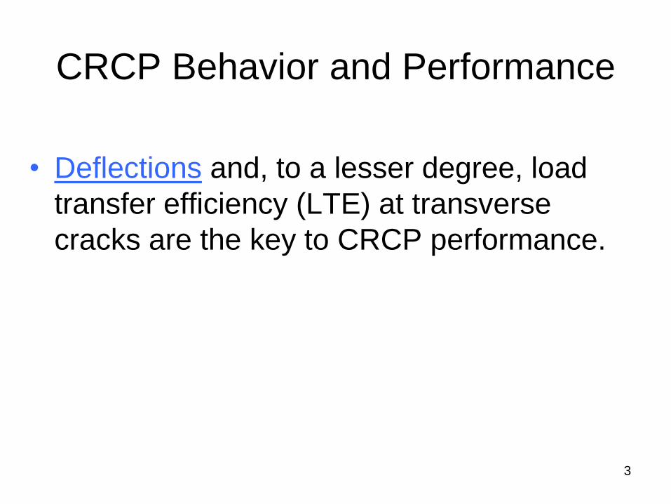
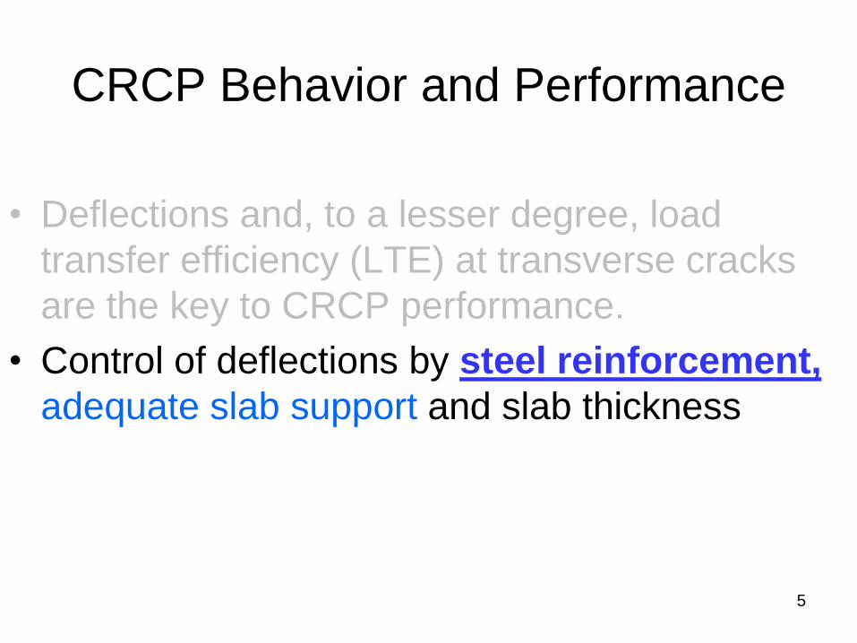
CRCP Behavior and Performance
• Deflections and, to a lesser degree, load
transfer efficiency (LTE) at transverse
cracks are the key to CRCP performance.
3
0
1
2
3
4
5
6
7
8
6 7 8 9 10 11 12 13 14 15
De
fle
cti
on
@ 9
,00
0 lb
s [
mil
s]
Slab Thickness (in)
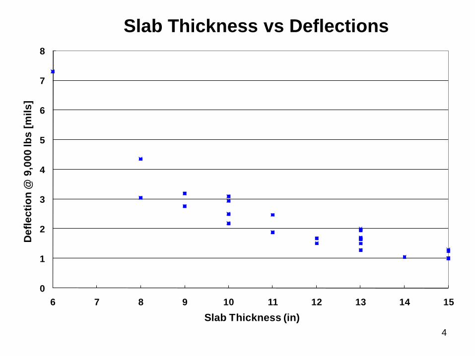
Slab Thickness vs Deflections
4
CRCP Behavior and Performance
• Deflections and, to a lesser degree, load
transfer efficiency (LTE) at transverse cracks
are the key to CRCP performance.
• Control of deflections by steel reinforcement,
adequate slab support and slab thickness
5
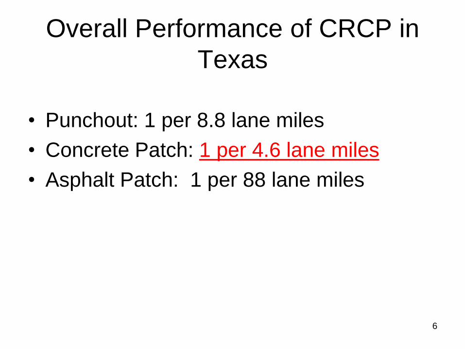
Overall Performance of CRCP in
Texas
• Punchout: 1 per 8.8 lane miles
• Concrete Patch: 1 per 4.6 lane miles
• Asphalt Patch: 1 per 88 lane miles
6
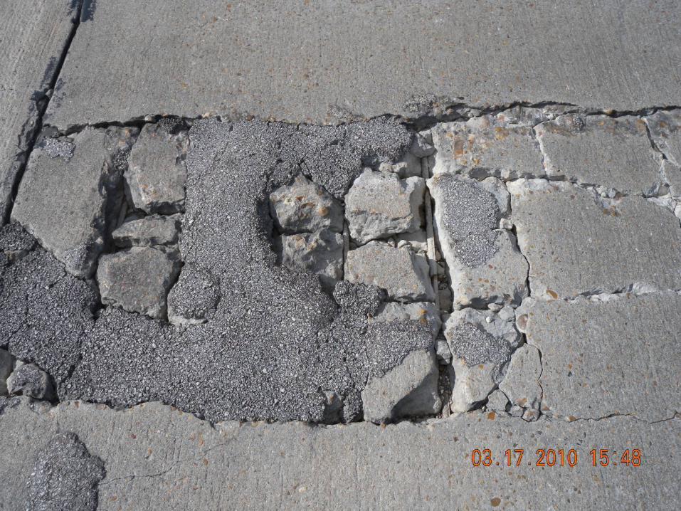
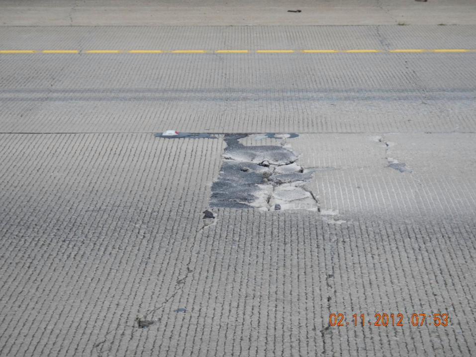
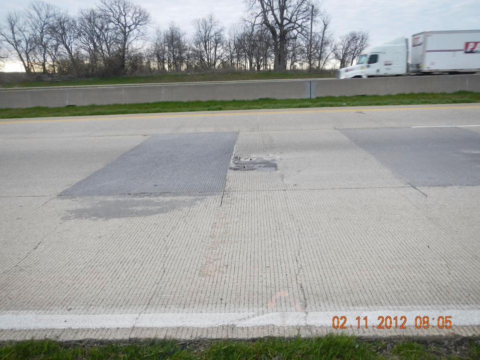
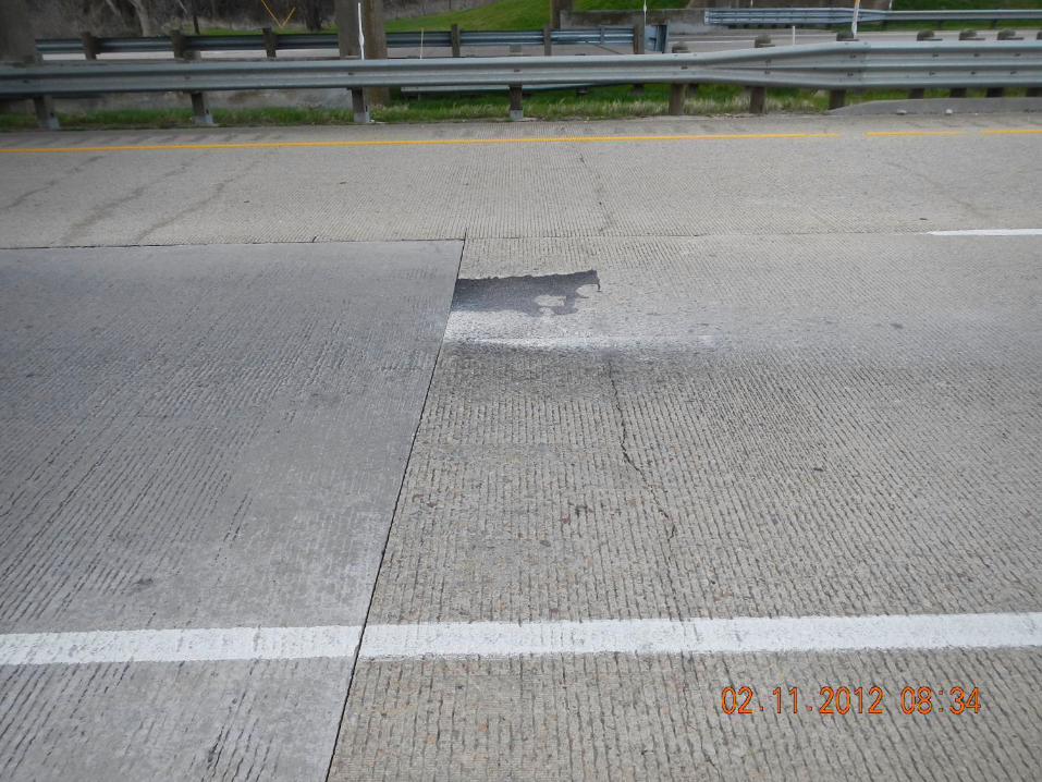
7
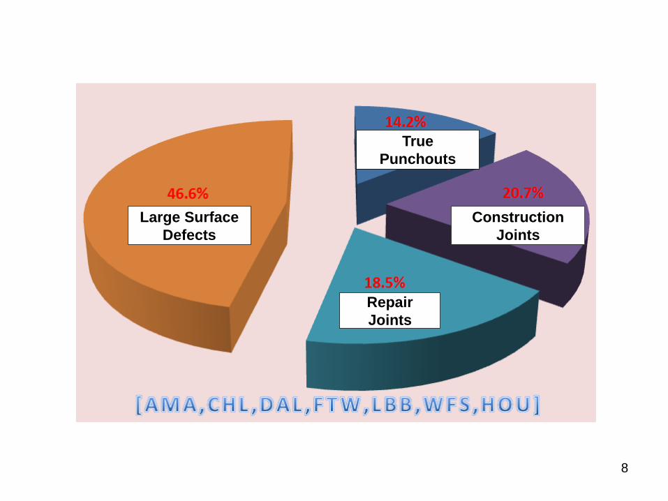
Large Surface
Defects
Repair
Joints
Construction
Joints
True
Punchouts
8
FULL-DEPTH REPAIR OF CRCP
9
10
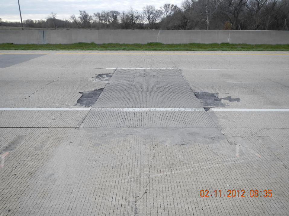
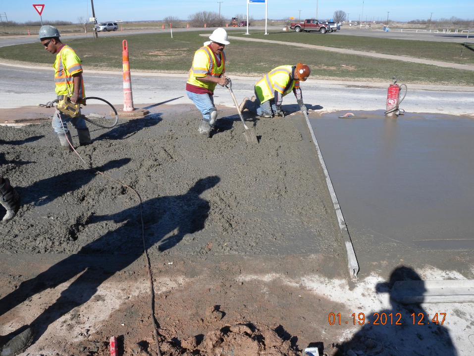
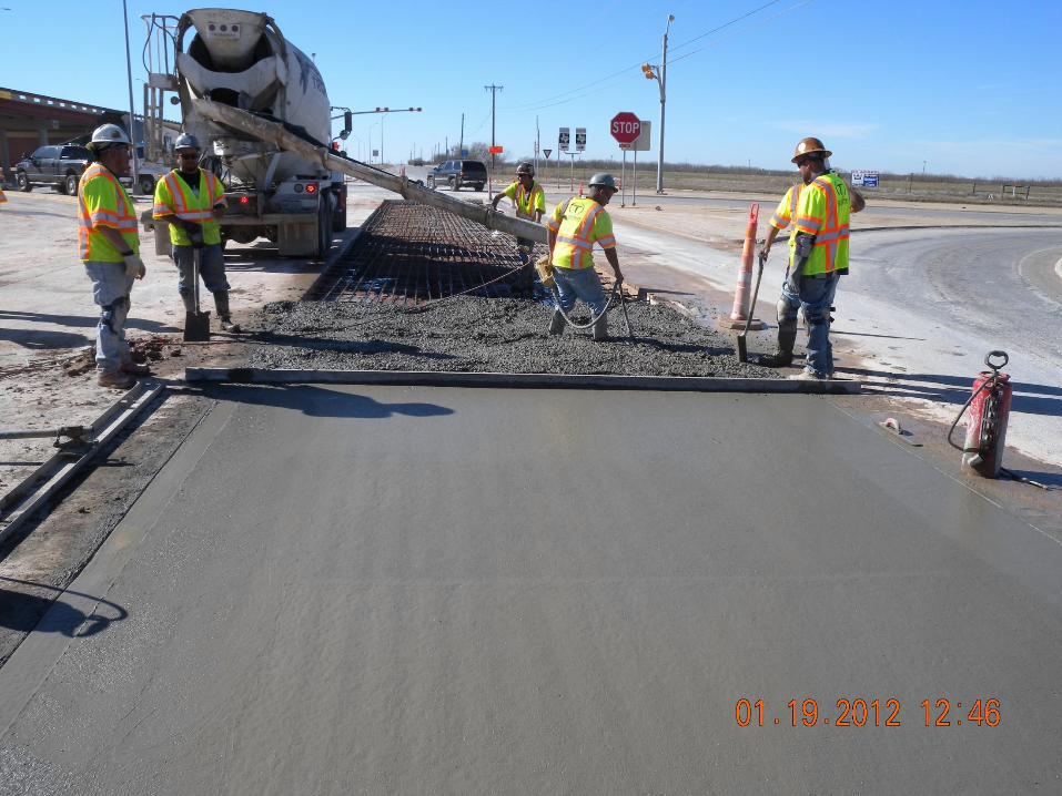
Full-Depth Repair of CRCP
• Conduct only when needed. (i.e., when
CRCP distress extends through the slab
depth)
• If distresses are limited to the top half of
the slab, use partial-depth repair.
11
Key to Successful Full-Depth
CRCP Repairs
• Lower deflections at transverse repair
joints
• Sound base support along the perimeter of
repair areas
12
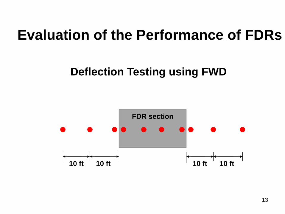
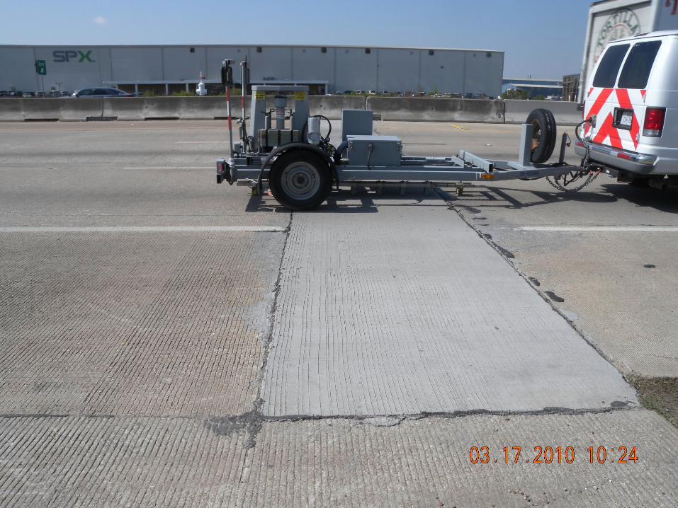
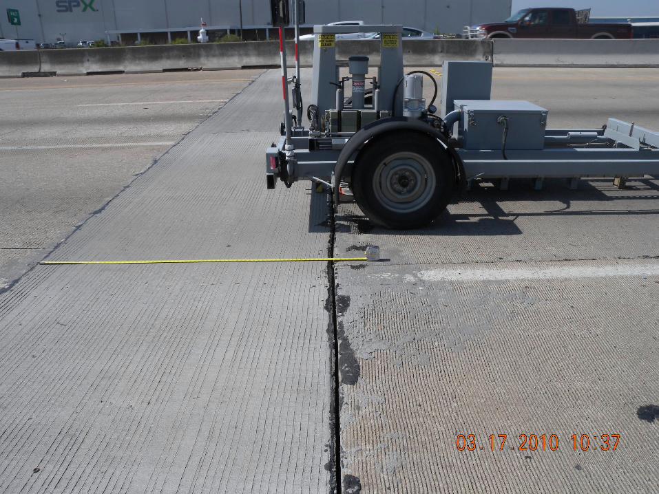
Evaluation of the Performance of FDRs
10 ft 10 ft 10 ft 10 ft
FDR section
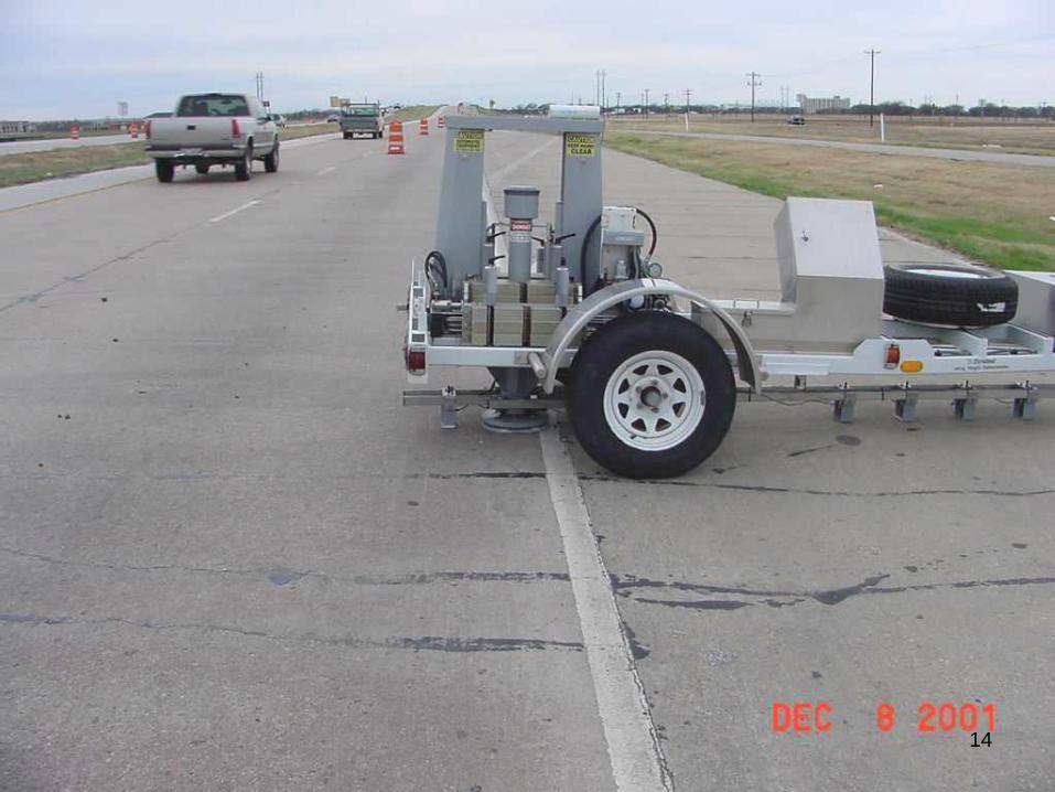
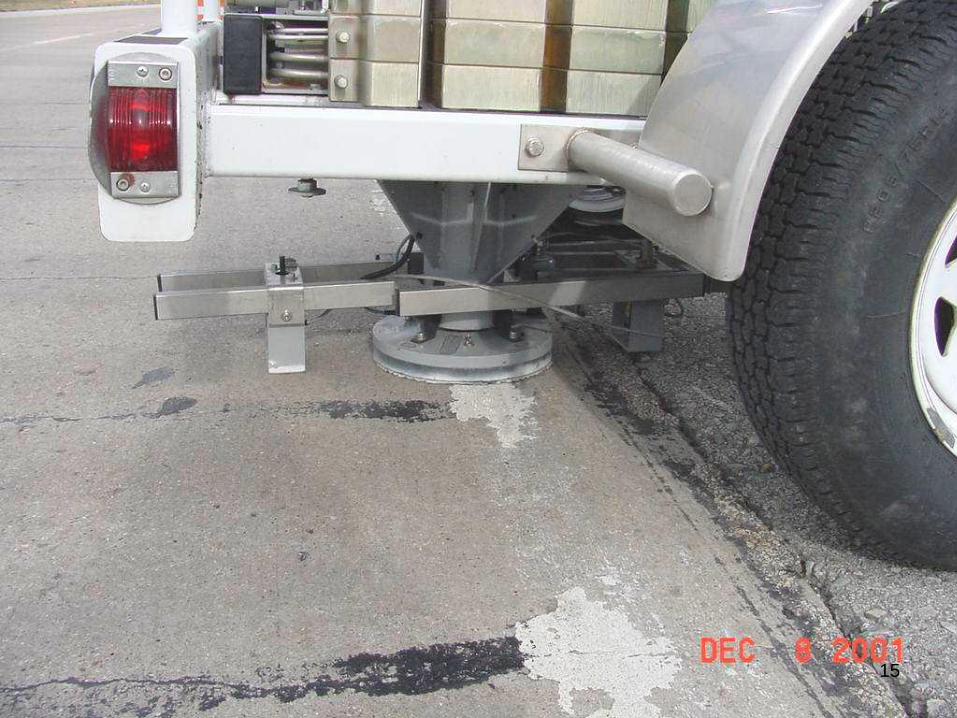
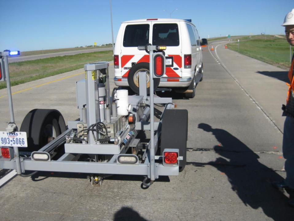
Deflection Testing using FWD
13
14
15
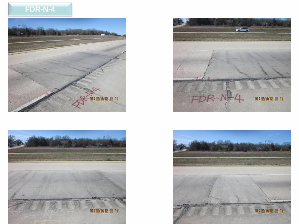
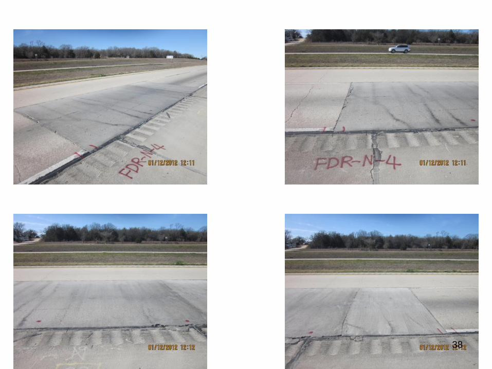
FDR-N-4
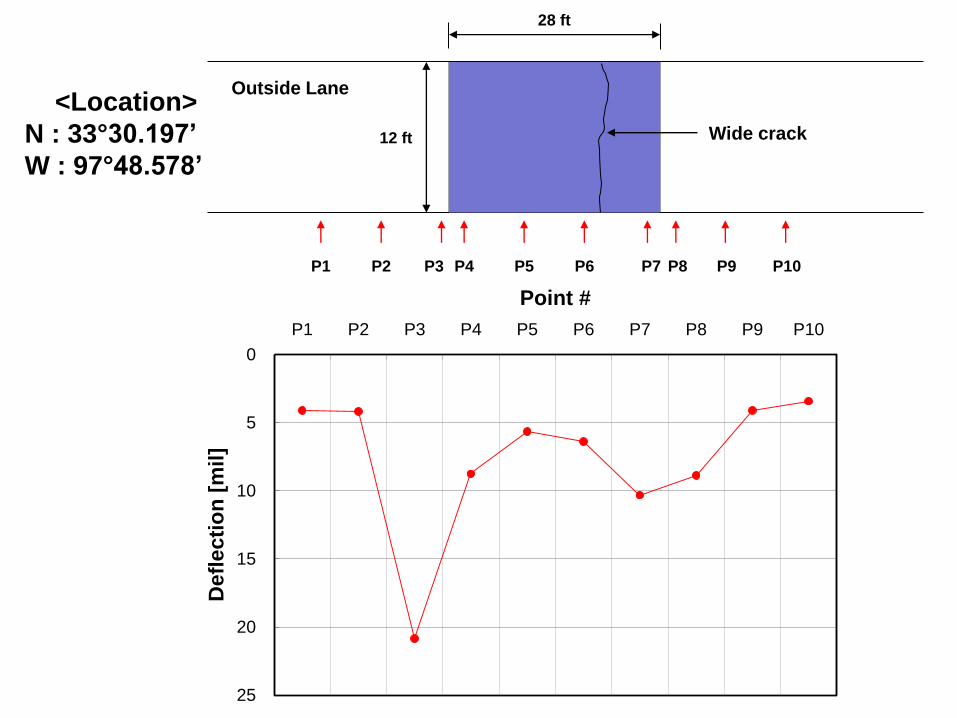
<Location>
N : 33°30.197’
W : 97°48.578’
Outside Lane
P1 P2 P3 P4 P5 P6
12 ft
28 ft
P7 P8 P9 P10
0
5
10
15
20
25
P1 P2 P3 P4 P5 P6 P7 P8 P9 P10
Point #
Defl
ecti
on
[m
il]
Wide crack
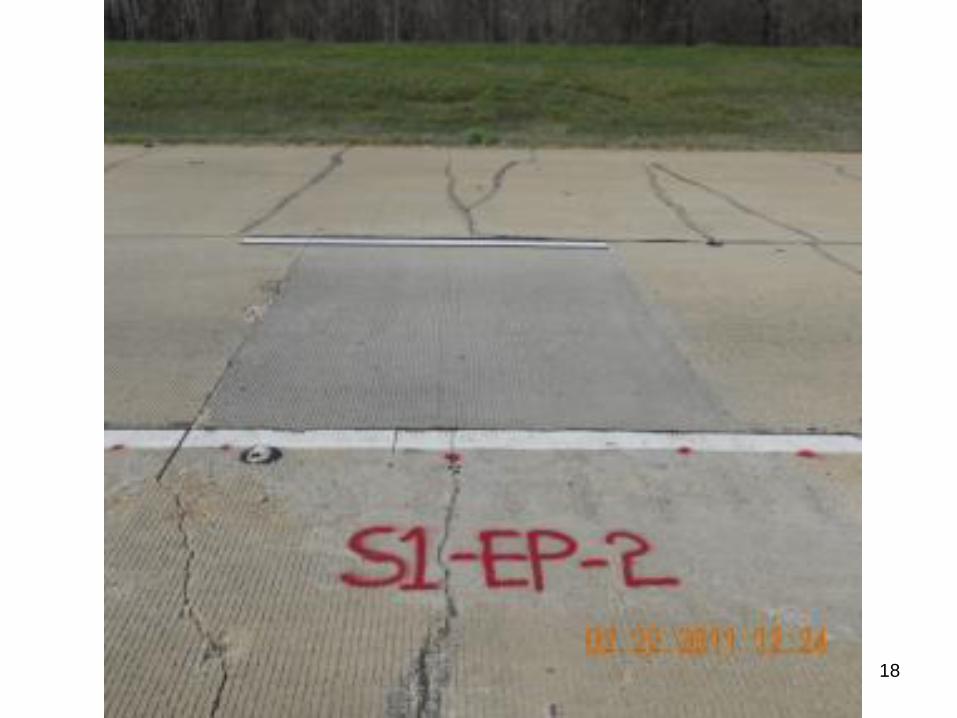
18
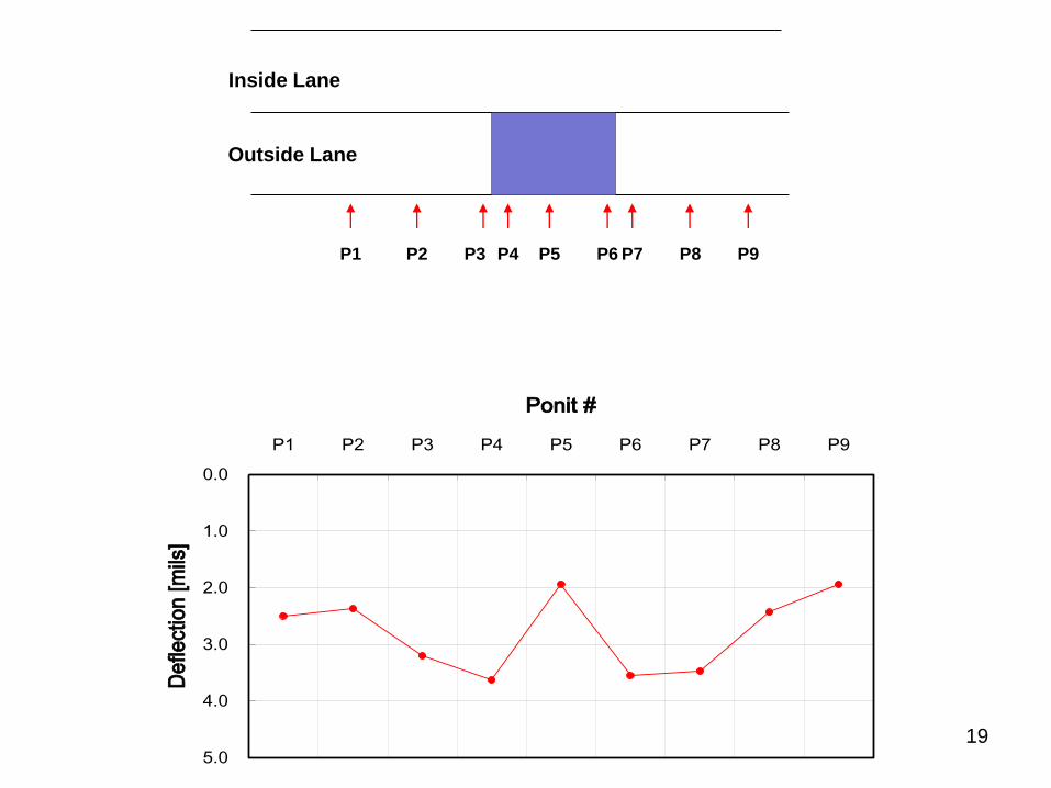
Inside Lane
Outside Lane
P1 P2 P3 P4 P5 P6 P7 P8 P9
0.0
1.0
2.0
3.0
4.0
5.0
P1 P2 P3 P4 P5 P6 P7 P8 P9
Ponit #
De
flect
ion
[m
ils]
19
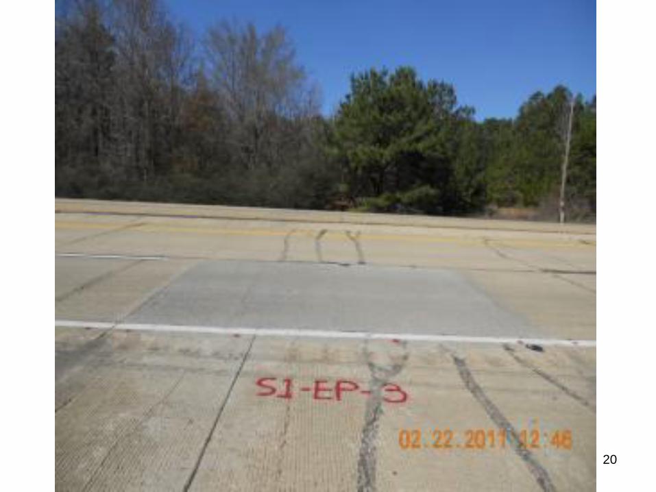
20
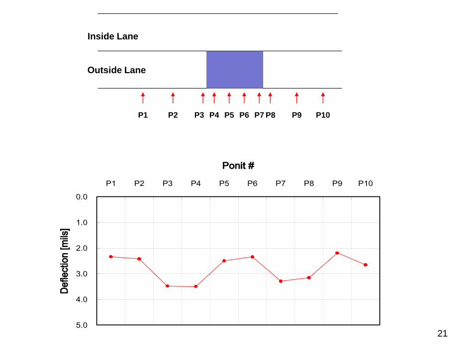
Inside Lane
Outside Lane
P1 P2 P3 P4 P5 P6 P7 P8 P9 P10
0.0
1.0
2.0
3.0
4.0
5.0
P1 P2 P3 P4 P5 P6 P7 P8 P9 P10
Ponit #
De
flect
ion
[m
ils]
21
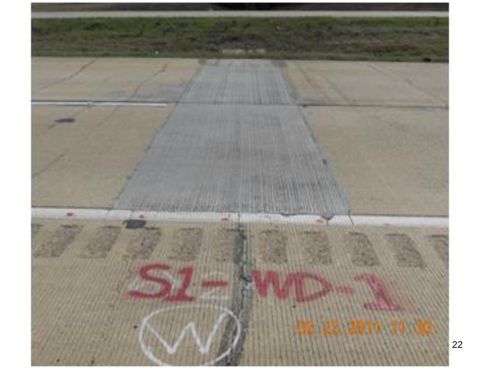
22
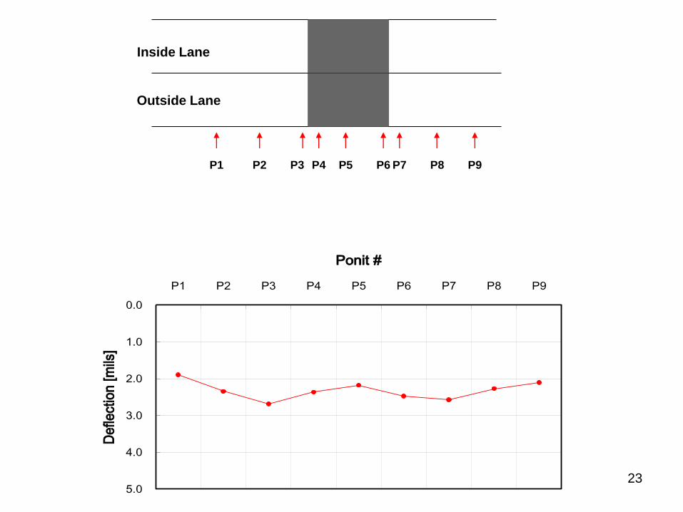
Inside Lane
Outside Lane
P1 P2 P3 P4 P5 P6 P7 P8 P9
0.0
1.0
2.0
3.0
4.0
5.0
P1 P2 P3 P4 P5 P6 P7 P8 P9
Ponit #
De
flect
ion
[m
ils]
23
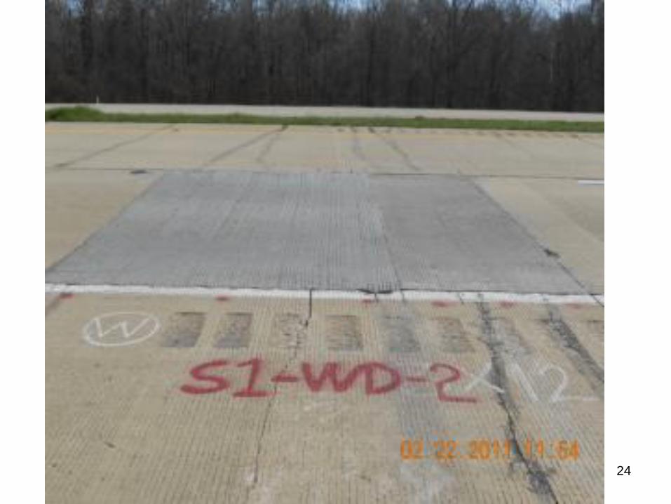
24
Inside Lane
Outside Lane
Welded
Epoxy
P1 P2 P3 P4 P5 P6 P7 P8 P9 P11 P12 P10
0.0
1.0
2.0
3.0
4.0
5.0
P1 P2 P3 P4 P5 P6 P7 P8 P9 P10 P11 P12
Ponit #
De
flect
ion
[m
ils]
25
26
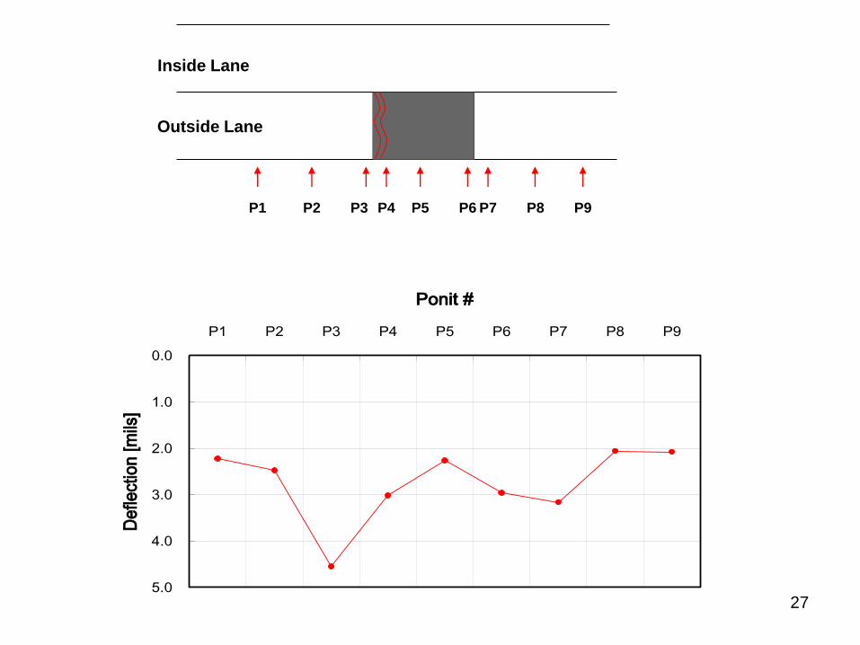
Inside Lane
Outside Lane
P1 P2 P3 P4 P5 P6 P7 P8 P9
0.0
1.0
2.0
3.0
4.0
5.0
P1 P2 P3 P4 P5 P6 P7 P8 P9
Ponit #
De
flect
ion
[m
ils]
27
28
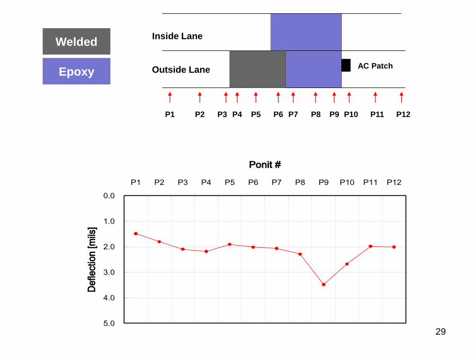
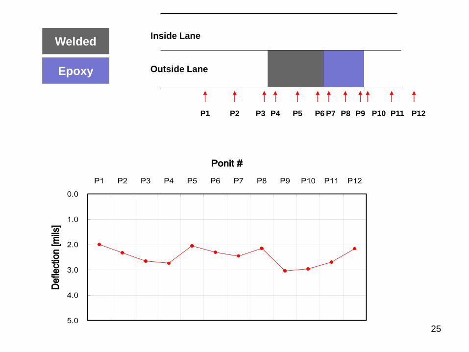
Inside Lane
Outside Lane
Welded
Epoxy
P1 P2 P3 P4 P5 P6 P7 P8 P9 P10 P11 P12
0.0
1.0
2.0
3.0
4.0
5.0
P1 P2 P3 P4 P5 P6 P7 P8 P9 P10 P11 P12
Ponit #
De
flect
ion
[m
ils]
AC Patch
29
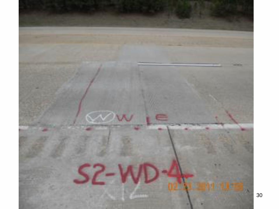
30
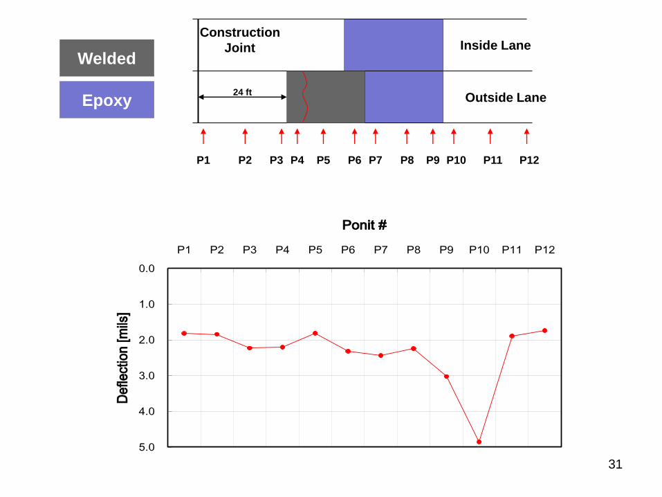
Inside Lane
Outside Lane
Welded
Epoxy
P1 P2 P3 P4 P5 P6 P7 P8 P9 P10 P11 P12
0.0
1.0
2.0
3.0
4.0
5.0
P1 P2 P3 P4 P5 P6 P7 P8 P9 P10 P11 P12
Ponit #
De
flect
ion
[m
ils]
Construction
Joint
24 ft
31
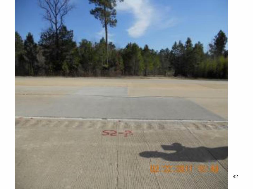
32
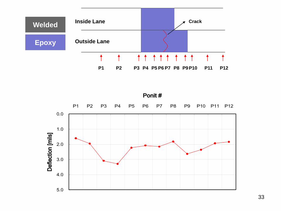
Inside Lane
Outside Lane
Welded
Epoxy
P1 P2 P3 P4 P5 P6 P7 P8 P9 P10 P11 P12
Crack
0.0
1.0
2.0
3.0
4.0
5.0
P1 P2 P3 P4 P5 P6 P7 P8 P9 P10 P11 P12
Ponit #
De
flect
ion
[m
ils]
33
34
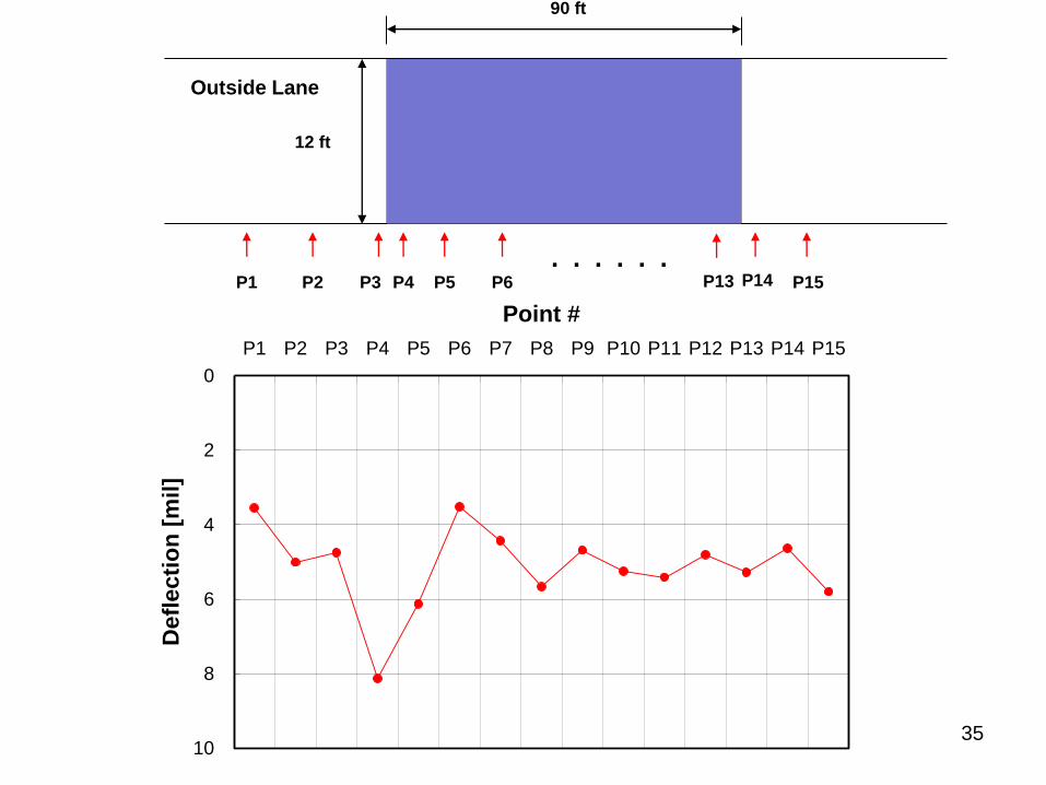
Outside Lane
P1 P2 P3 P4 P5 P6 P14 P15
12 ft
P13 . . . . . .
90 ft
0
2
4
6
8
10
P1 P2 P3 P4 P5 P6 P7 P8 P9 P10 P11 P12 P13 P14 P15
Point #
Defl
ecti
on
[m
il]
35
36
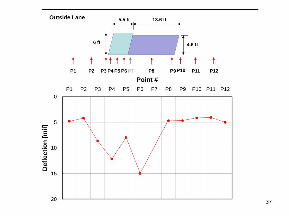
Outside Lane
P1 P2 P3 P4 P5 P6 P8 P9
6 ft
P7
5.5 ft 13.6 ft
4.6 ft
P10 P11 P12
0
5
10
15
20
P1 P2 P3 P4 P5 P6 P7 P8 P9 P10 P11 P12
Point #
Defl
ecti
on
[m
il]
37
38
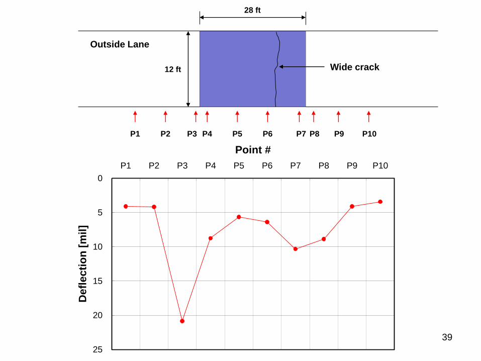
Outside Lane
P1 P2 P3 P4 P5 P6
12 ft
28 ft
P7 P8 P9 P10
0
5
10
15
20
25
P1 P2 P3 P4 P5 P6 P7 P8 P9 P10
Point #
Defl
ecti
on
[m
il]
Wide crack
39
40
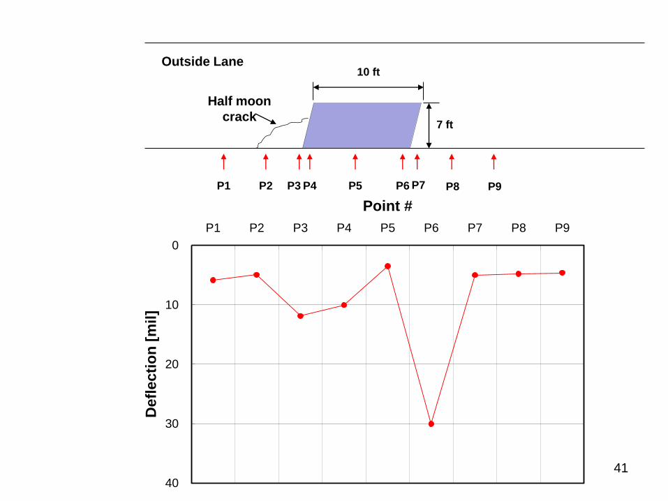
Outside Lane
P1 P2 P3 P4 P5 P6
7 ft
10 ft
P7 P8 P9
Half moon
crack
0
10
20
30
40
P1 P2 P3 P4 P5 P6 P7 P8 P9
Point #
Defl
ecti
on
[m
il]
41
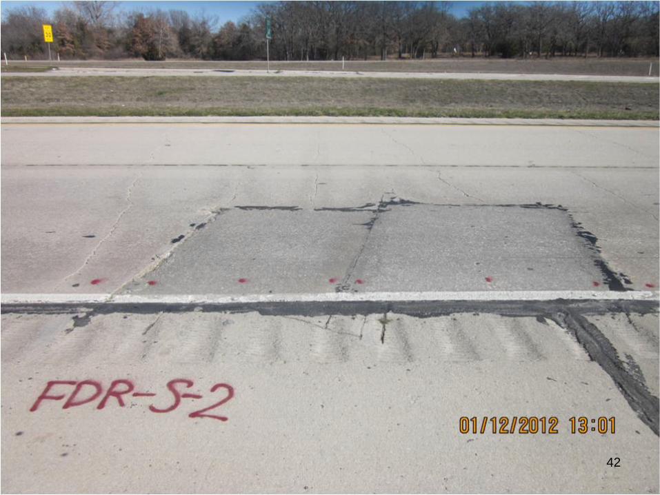
42
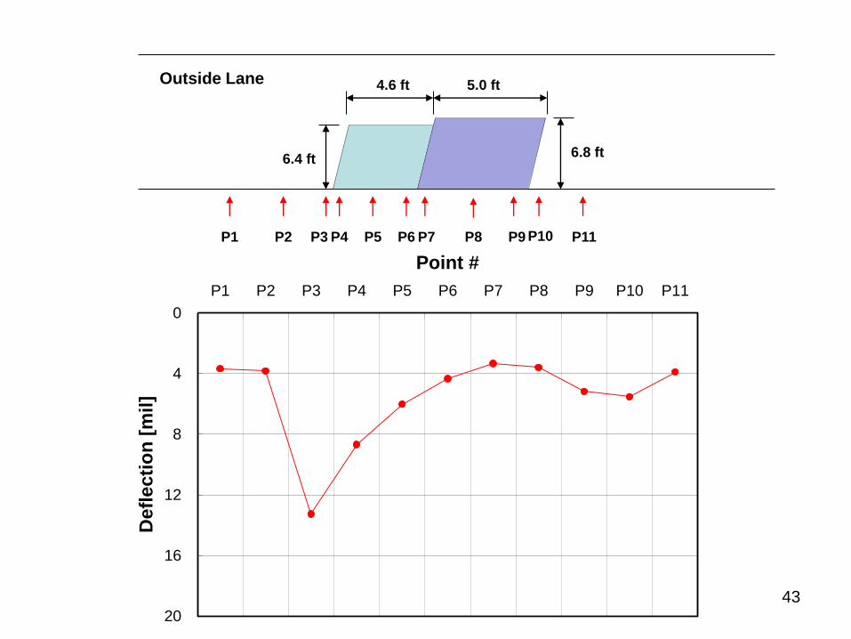
Outside Lane
P1 P2 P3 P4 P5 P6 P8 P9
6.4 ft
P7
4.6 ft 5.0 ft
6.8 ft
P10 P11
0
4
8
12
16
20
P1 P2 P3 P4 P5 P6 P7 P8 P9 P10 P11
Point #
Defl
ecti
on
[m
il]
43
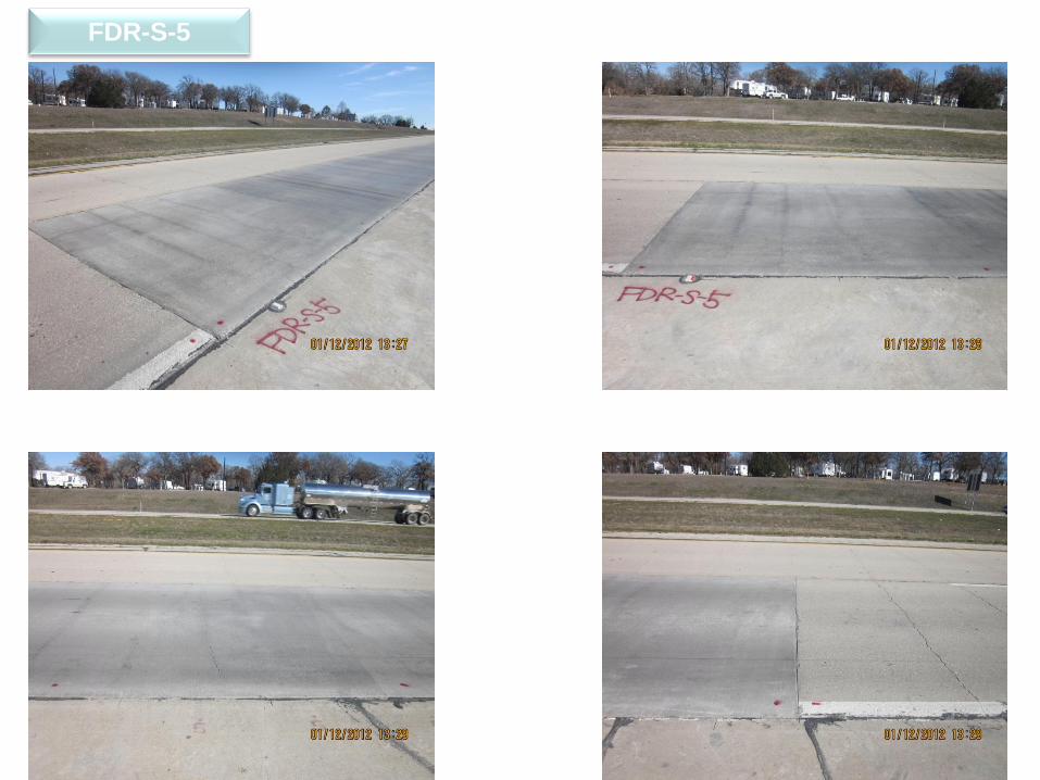
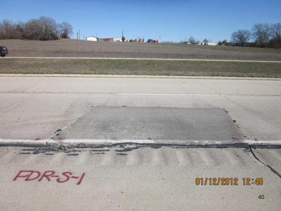
FDR-S-5
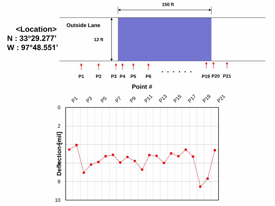
<Location>
N : 33°29.277’
W : 97°48.551’
Outside Lane
P1 P2 P3 P4 P5 P6 P21
12 ft
P20 . . . . . .
150 ft
P19
0
2
4
6
8
10
P1
P3
P5
P7
P9
P11
P13
P15
P17
P19
P21
Point #
Defl
ecti
on
[m
il]
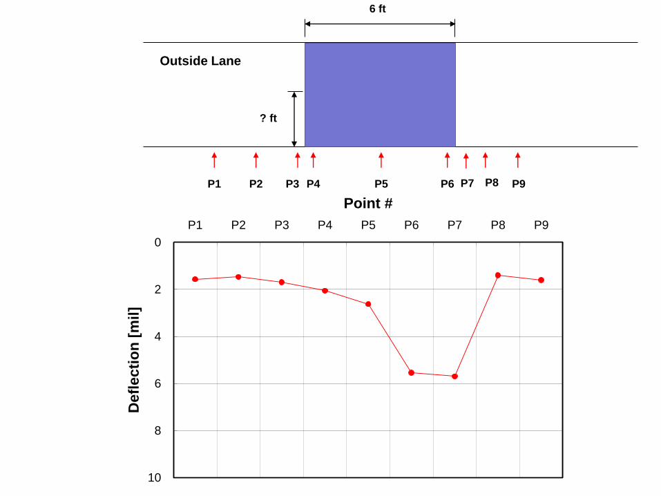
Outside Lane
P1 P2 P3 P4 P5 P6 P8 P9
? ft
P7
6 ft
0
2
4
6
8
10
P1 P2 P3 P4 P5 P6 P7 P8 P9
Point #
Defl
ecti
on
[m
il]
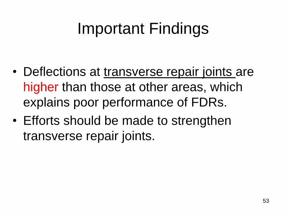
Important Findings
• Deflections at transverse repair joints are
higher than those at other areas, which
explains poor performance of FDRs.
• Efforts should be made to strengthen
transverse repair joints.
53

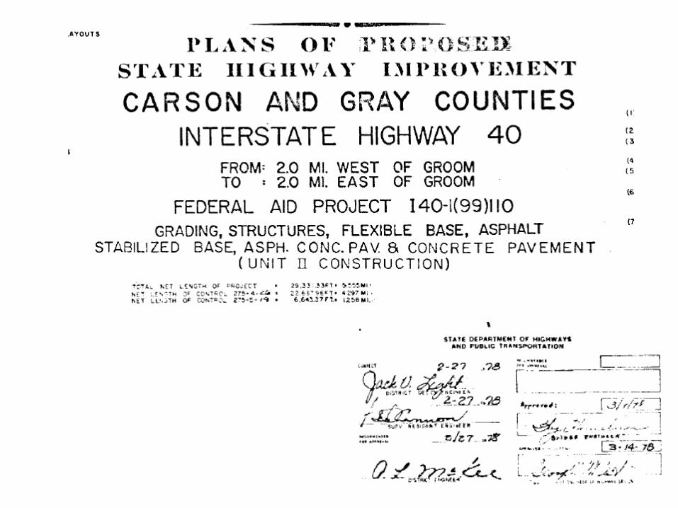
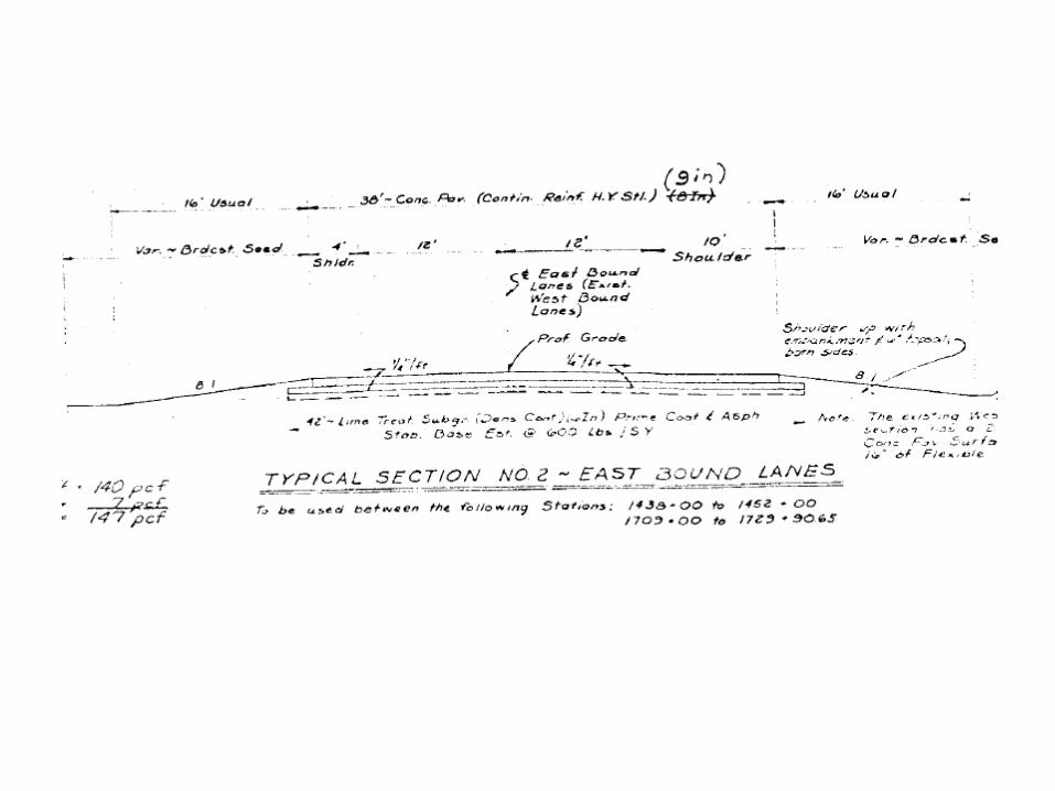
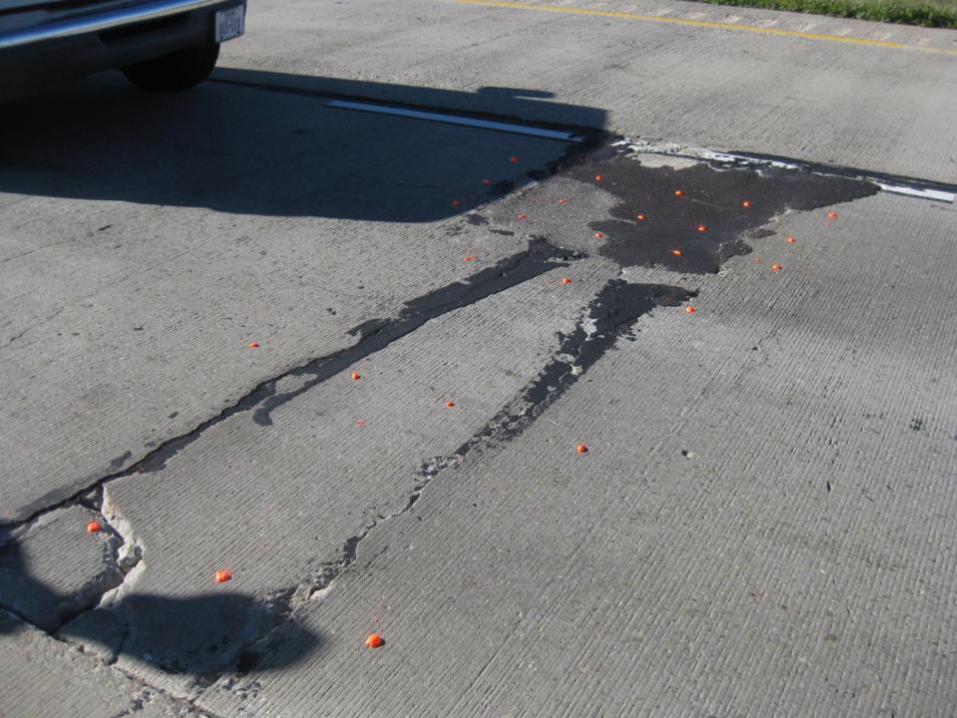
Amarillo IH 40
• 9-in CRCP + 600 #/SY ASB
• Completed in1979
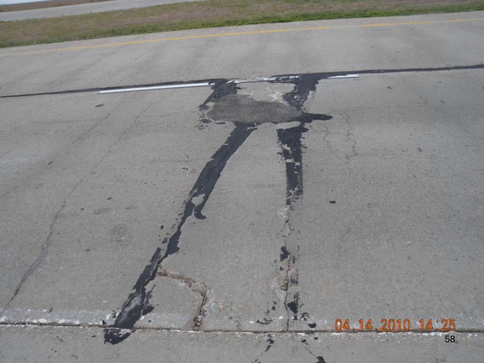
58
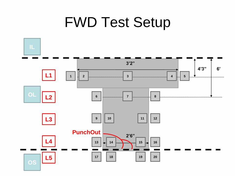
FWD Test Setup
3’2”
2’6”
OL
OS
IL
4’3”
1 2 3 4 5
6 7 8
9 10 11 12
6’
13 14 15 16
17 19 18
PunchOut
20
L1
L2
L3
L4
L5
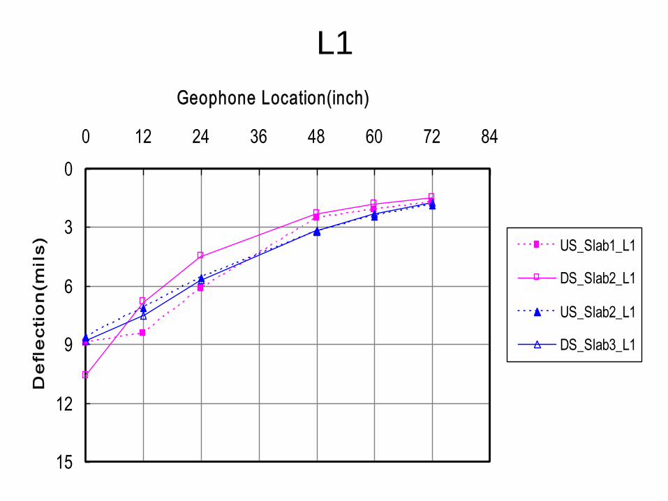
0
3
6
9
12
15
0 12 24 36 48 60 72 84
Geophone Location(inch)
De
fle
cti
on
(mil
s) US_Slab1_L1
DS_Slab2_L1
US_Slab2_L1
DS_Slab3_L1
L1

0
1
2
3
4
5
6
7
8
6 7 8 9 10 11 12 13 14 15
De
fle
cti
on
@ 9
,00
0 lb
s [
mil
s]
Slab Thickness (in)
Slab Thickness vs Deflections
63
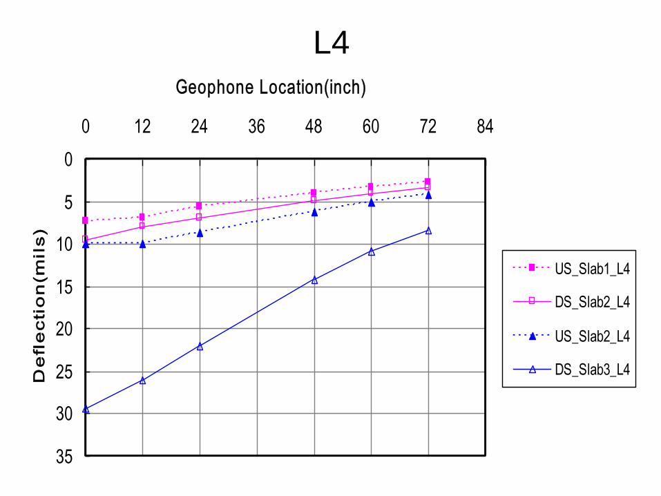
0
5
10
15
20
25
30
35
0 12 24 36 48 60 72 84
Geophone Location(inch)
De
fle
cti
on
(m
ils
)
US_Slab1_L4
DS_Slab2_L4
US_Slab2_L4
DS_Slab3_L4
L4
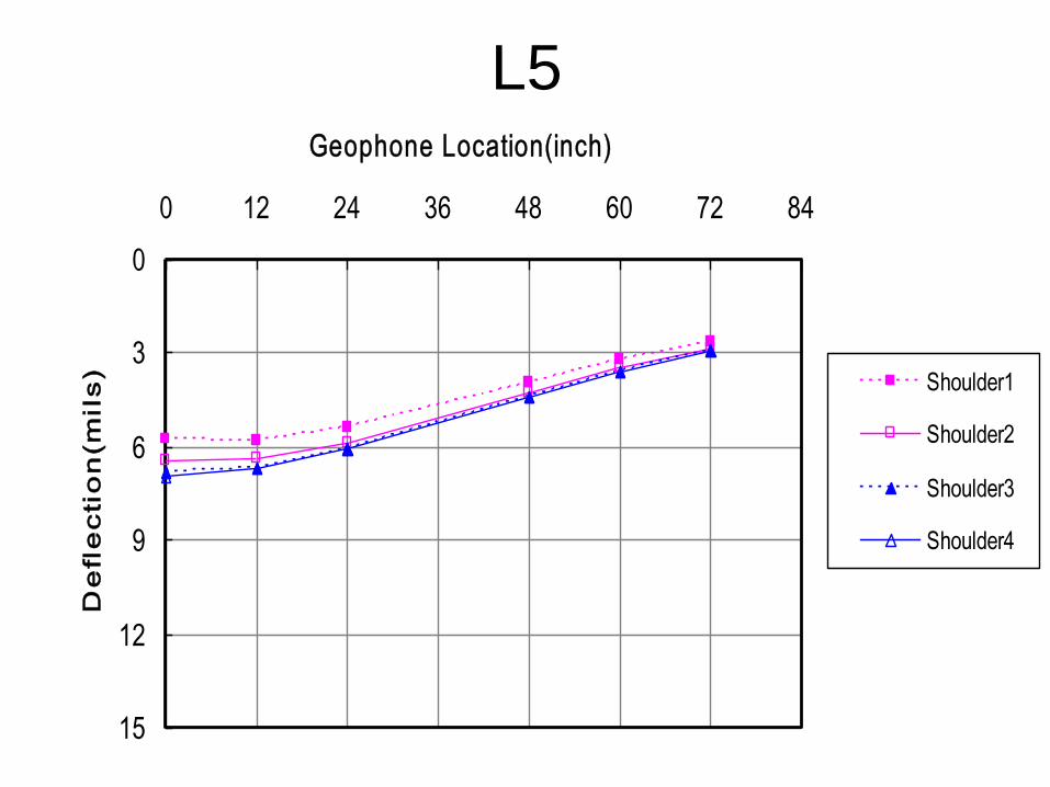
0
3
6
9
12
15
0 12 24 36 48 60 72 84
Geophone Location(inch)
De
fle
cti
on
(m
ils
) Shoulder1
Shoulder2
Shoulder3
Shoulder4
L5
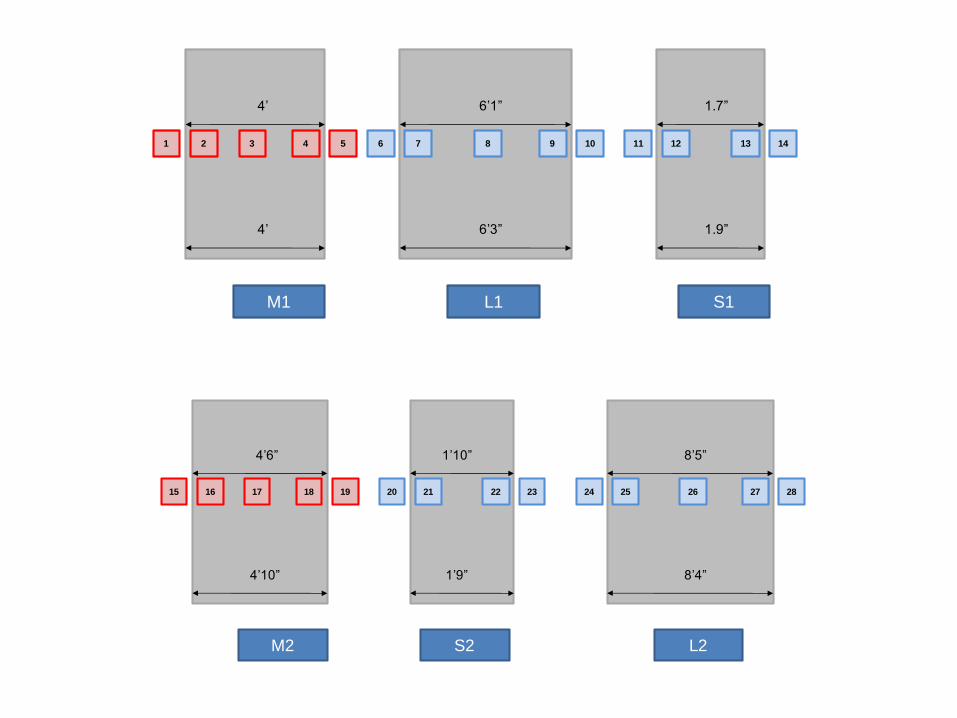
M1 L1 S1
1 2 3 4 5 6 7 8 9 10 11 12 13 14
4’ 6’1” 1.7”
4’ 6’3” 1.9”
M2 L2S2
15 16 17 18 19 25 26 27 2820 21 22 23 24
4’10” 8’4”
4’6” 8’5”
1’9”
1’10”
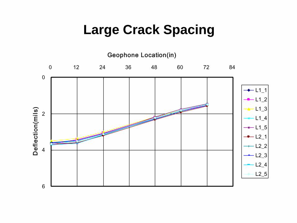
0
2
4
6
0 12 24 36 48 60 72 84
Geophone Location(in)
De
fle
cti
on
(mil
s)
L1_1
L1_2
L1_3
L1_4
L1_5
L2_1
L2_2
L2_3
L2_4
L2_5
Large Crack Spacing
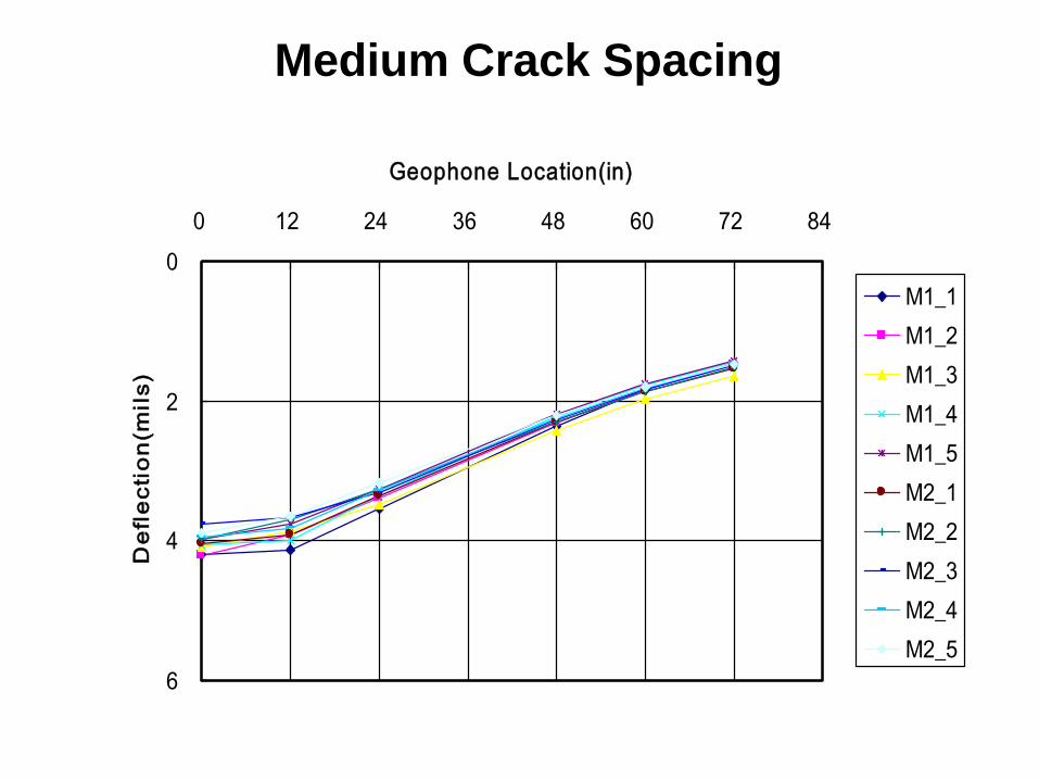
Medium Crack Spacing
0
2
4
6
0 12 24 36 48 60 72 84
Geophone Location(in)
De
fle
cti
on
(mil
s)
M1_1
M1_2
M1_3
M1_4
M1_5
M2_1
M2_2
M2_3
M2_4
M2_5
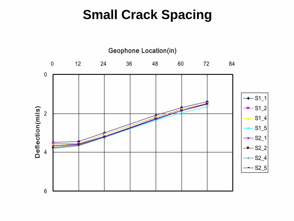
Small Crack Spacing
0
2
4
6
0 12 24 36 48 60 72 84
Geophone Location(in)
De
fle
cti
on
(mil
s)
S1_1
S1_2
S1_4
S1_5
S2_1
S2_2
S2_4
S2_5
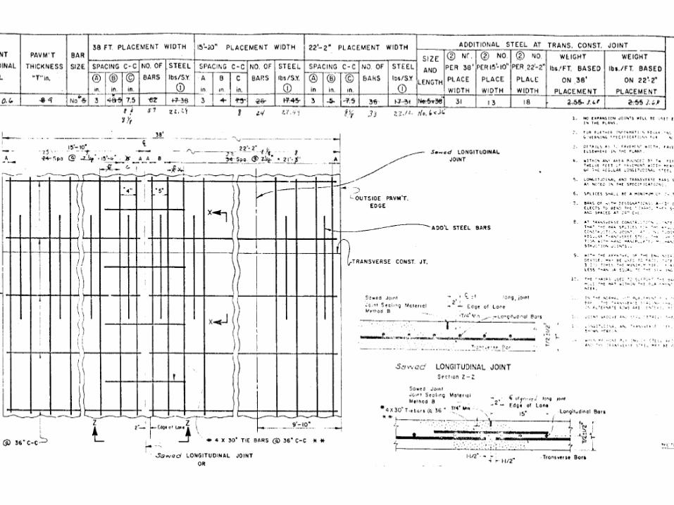
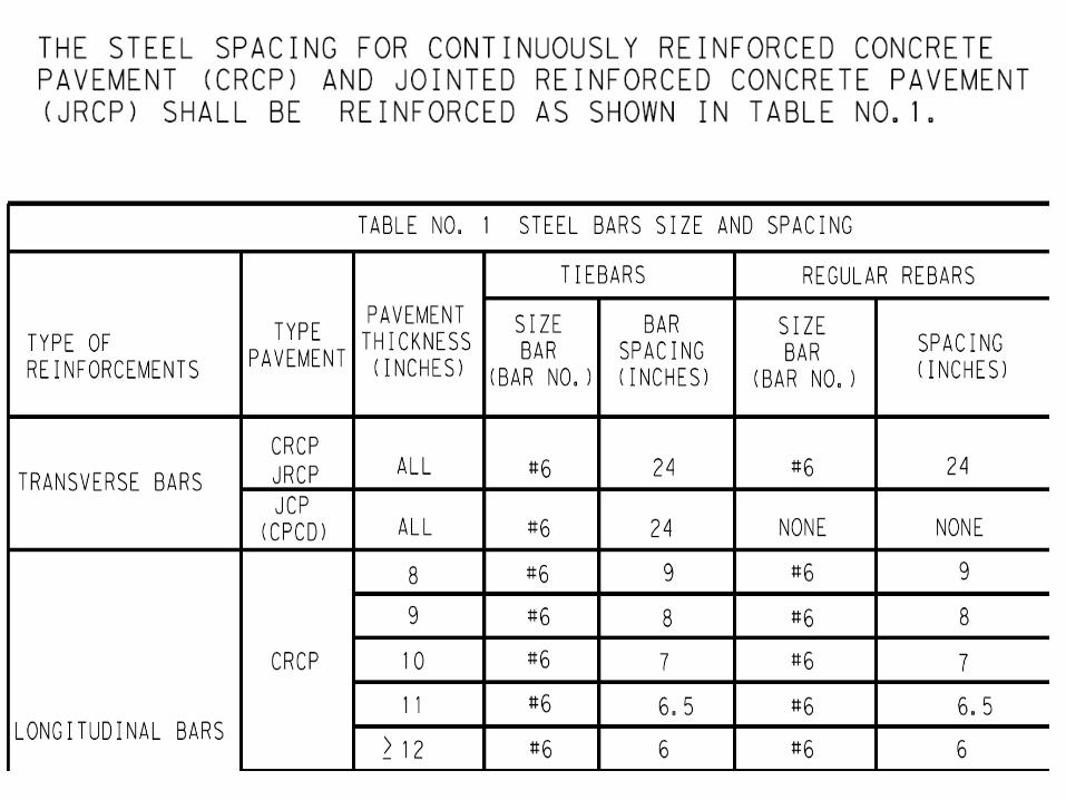
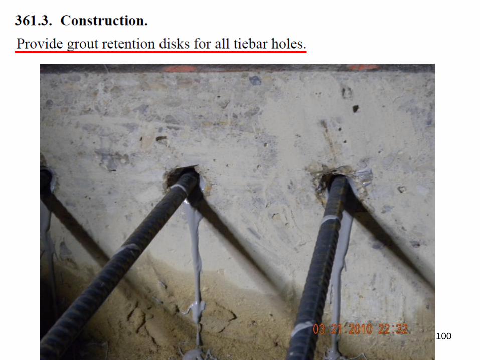
Review of Specifications Item 361
70
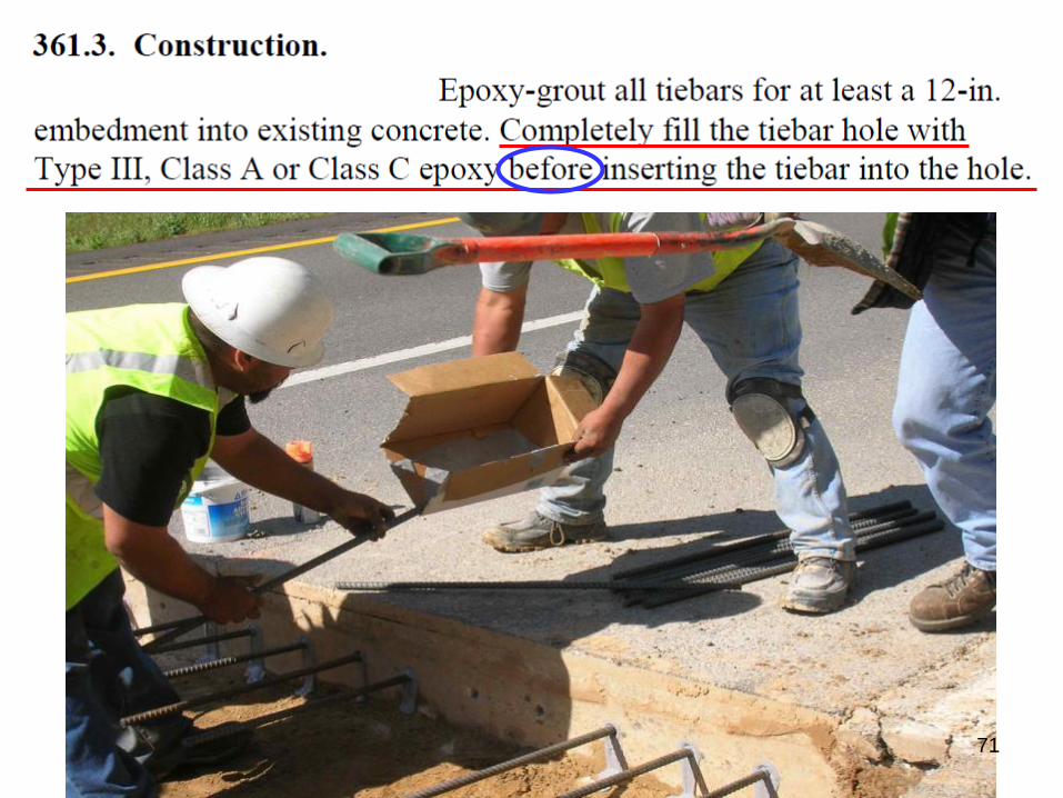
71
72

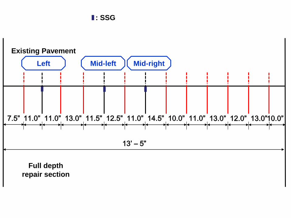
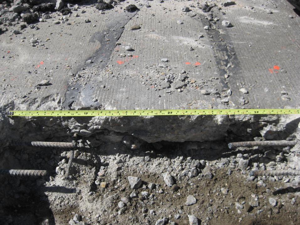
7.5” 11.0” 11.0” 13.0” 11.5” 12.5” 11.0” 14.5” 10.0” 11.0” 13.0” 12.0” 13.0” 10.0”
Existing Pavement
Full depth
repair section
13’ – 5”
Left Mid-left Mid-right
: SSG
80
-1,000
0
1,000
2,000
3,000
4,000
5,000
01-19-12 01-24-12 01-29-12 02-03-12
Time [day]
Str
ain
[μ
ε]
30
40
50
60
70
80
90
Te
mp
era
ture
[˚ F
]
Left Mid-left Mid-right Temp
86

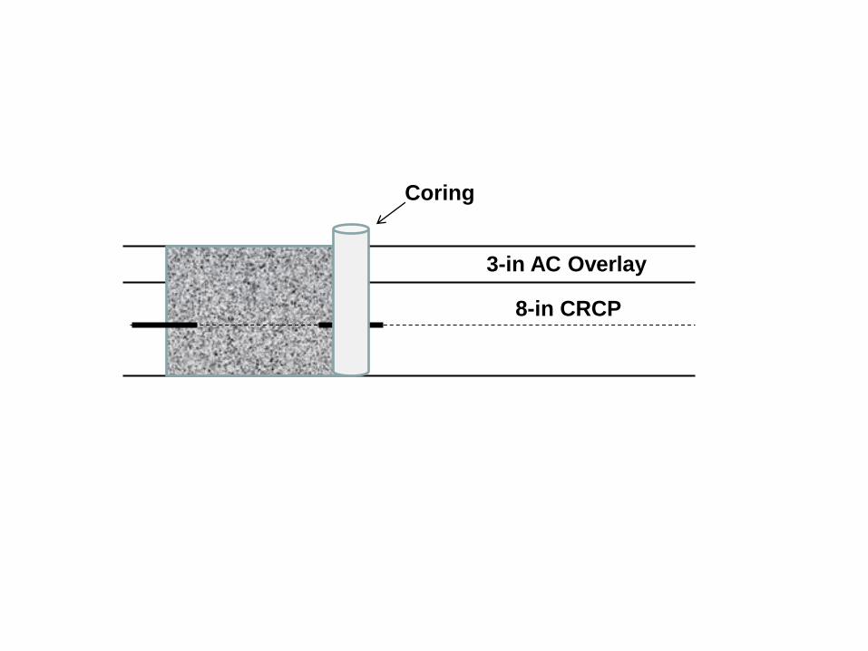
8-in CRCP
8-in CRCP
8-in CRCP
3-in AC Overlay
8-in CRCP
8-in CRCP
3-in AC Overlay
8-in CRCP
3-in AC Overlay
8-in CRCP
8-in CRCP
3-in AC Overlay
8-in CRCP
3-in AC Overlay
8-in CRCP
8-in CRCP
3-in AC Overlay
8-in CRCP
3-in AC Overlay
8-in CRCP
3-in AC Overlay
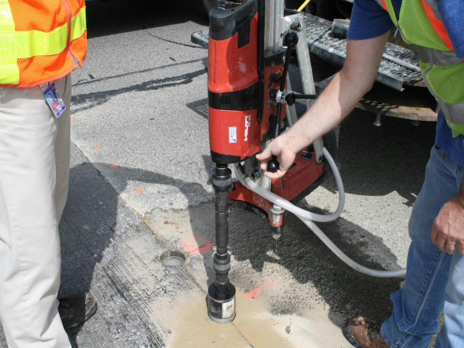
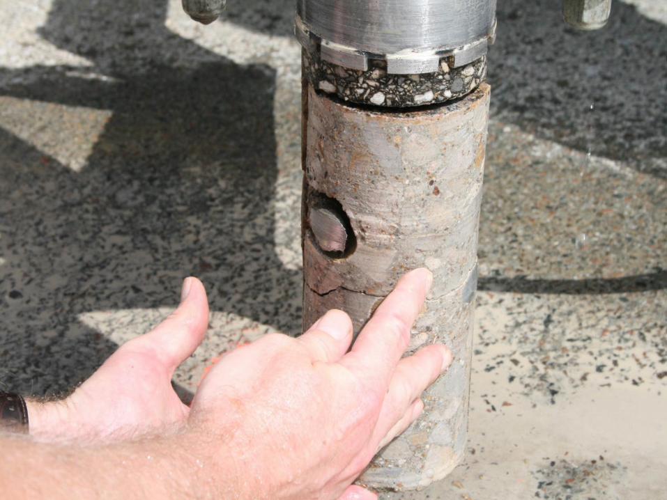
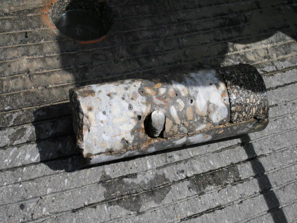
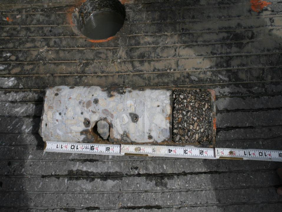
Coring
99
100
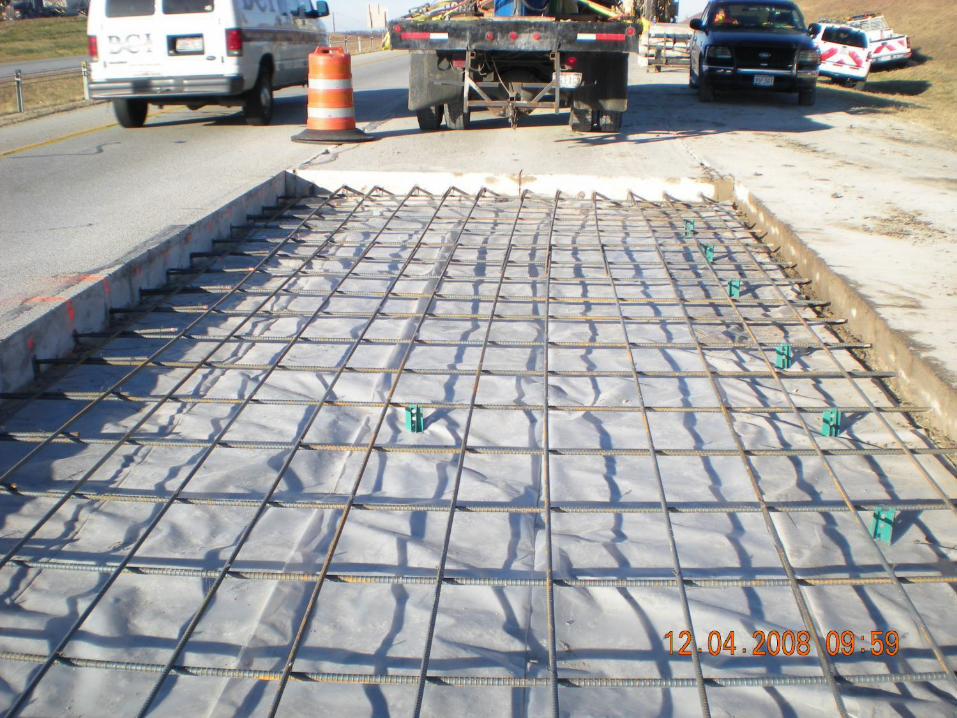
101
102
103
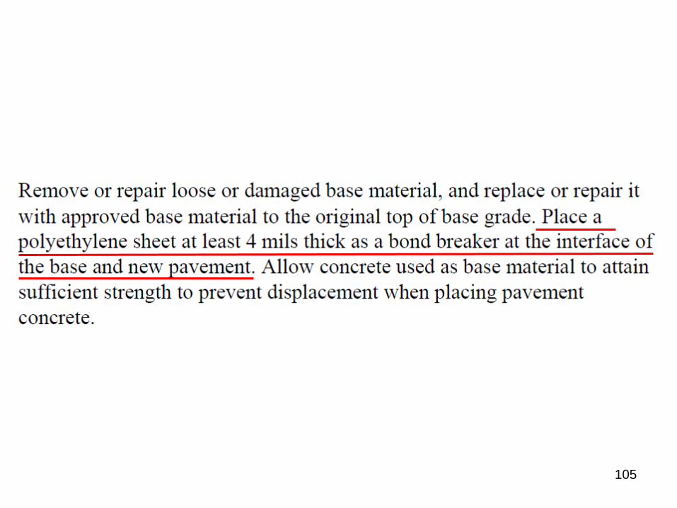
105
106
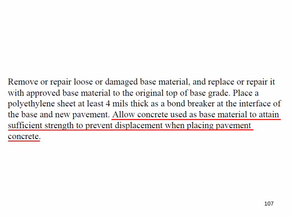
107
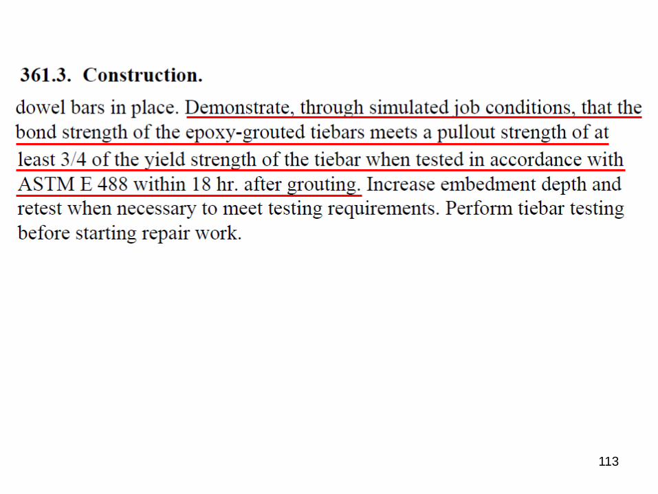
113
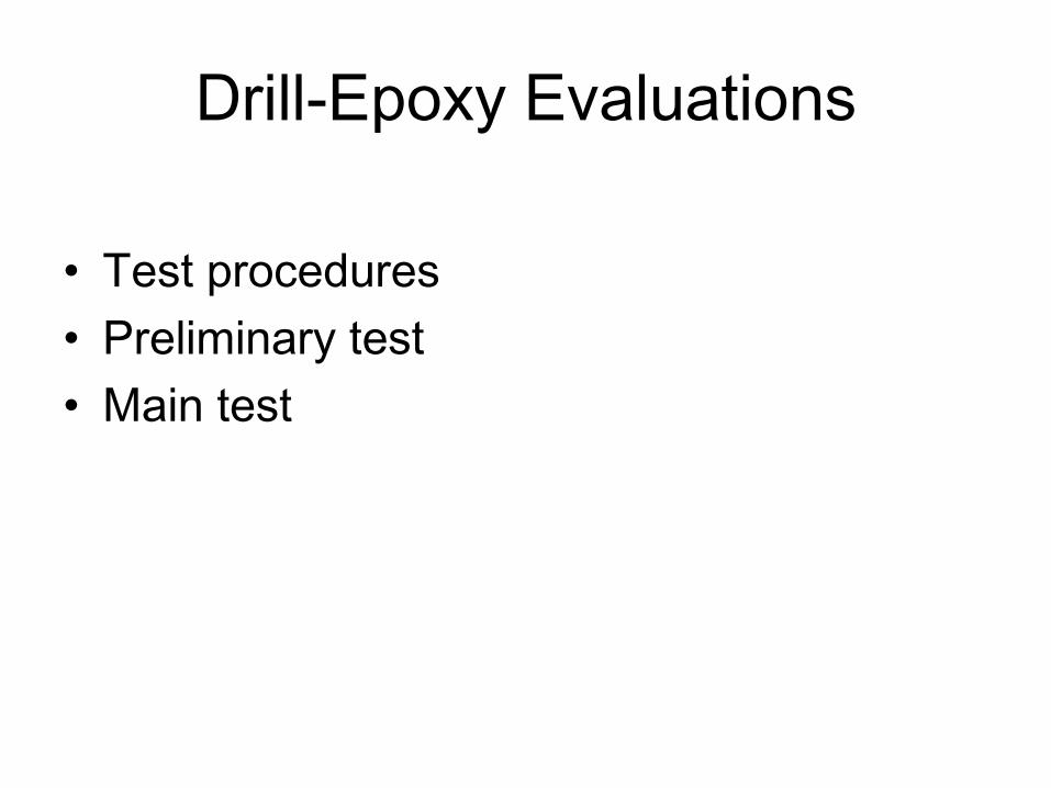
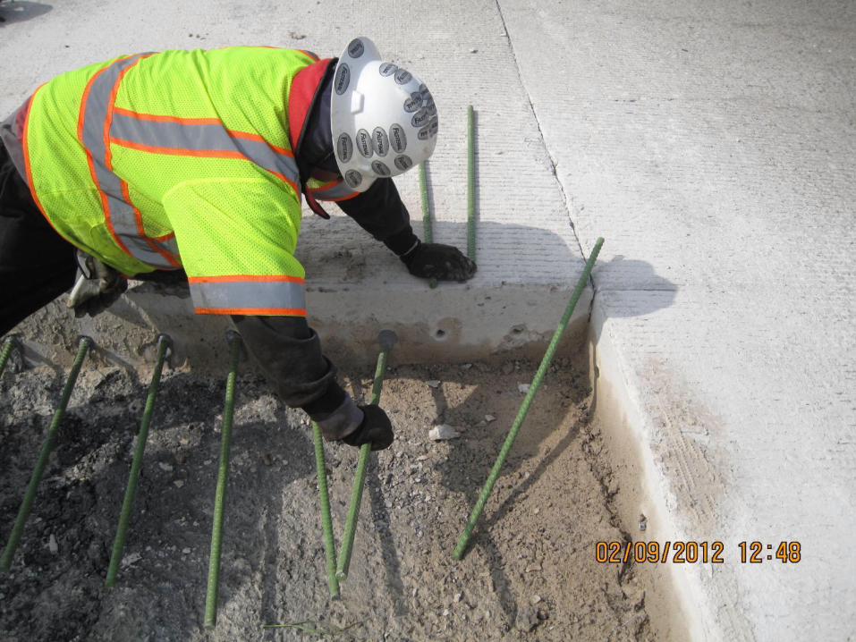
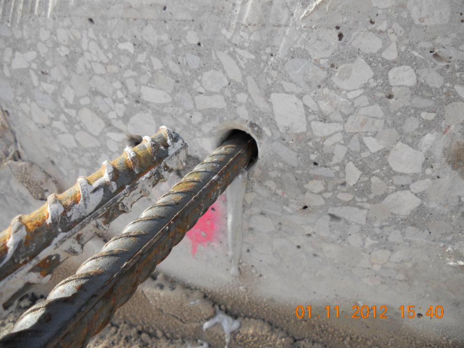
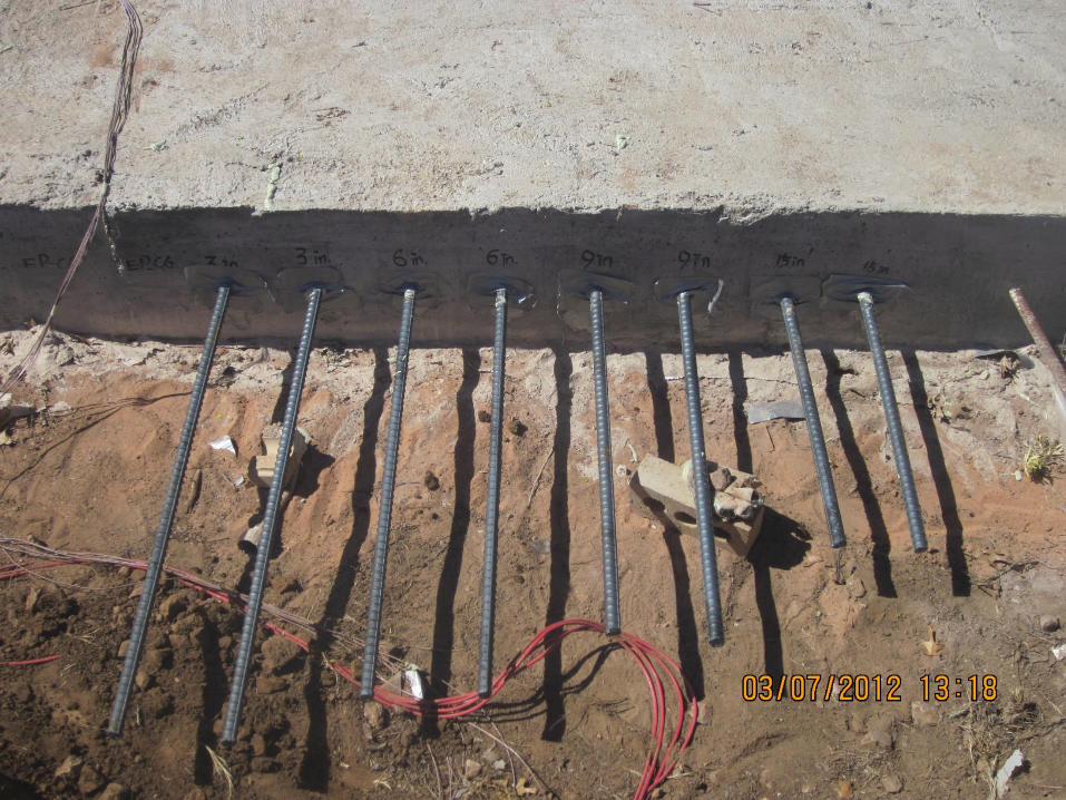
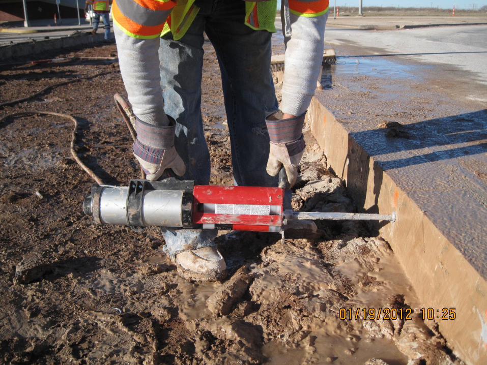
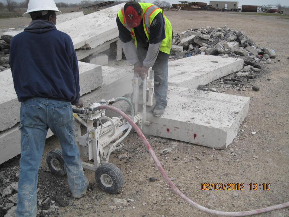
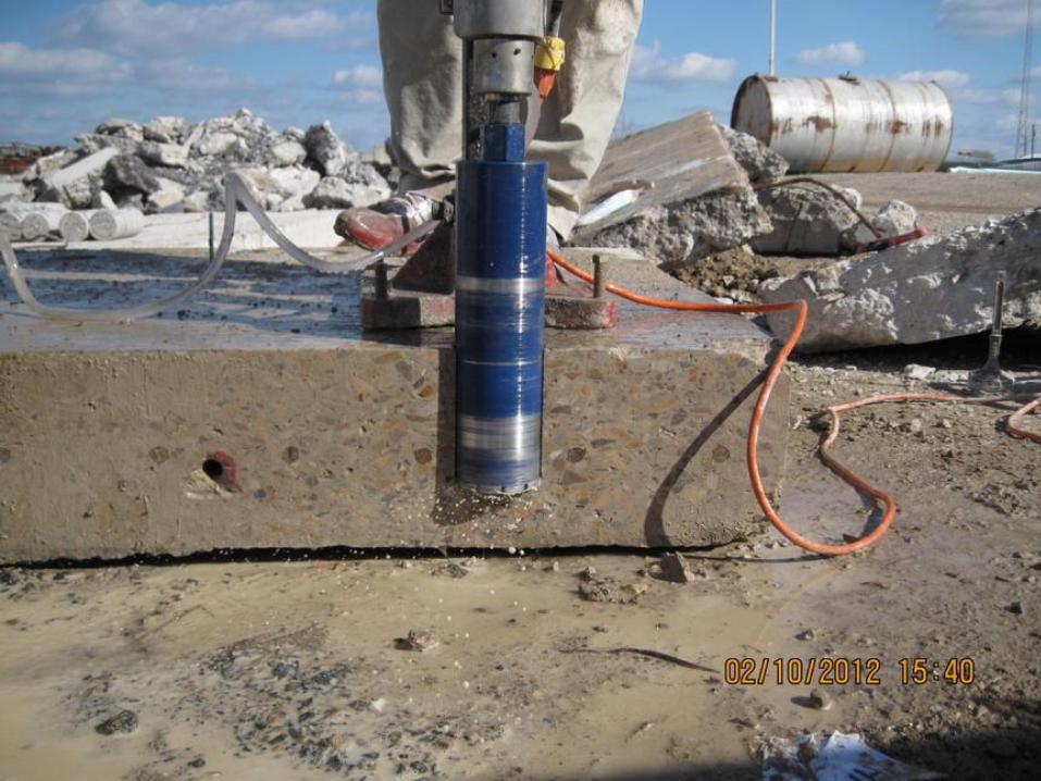
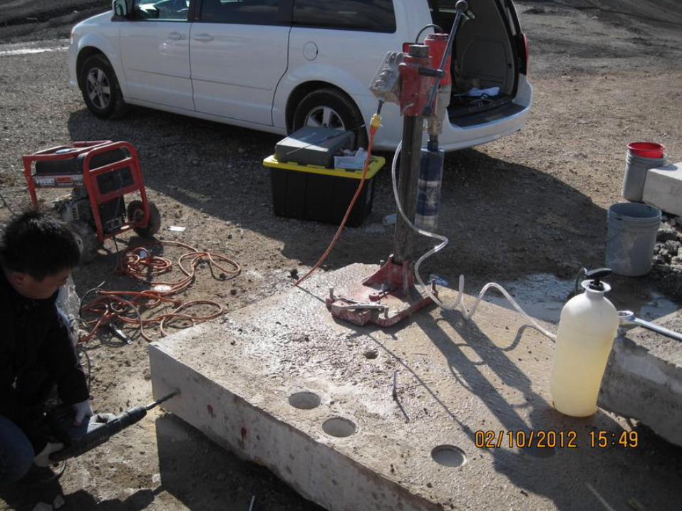
Drill-Epoxy Evaluations
• Test procedures
• Preliminary test
• Main test
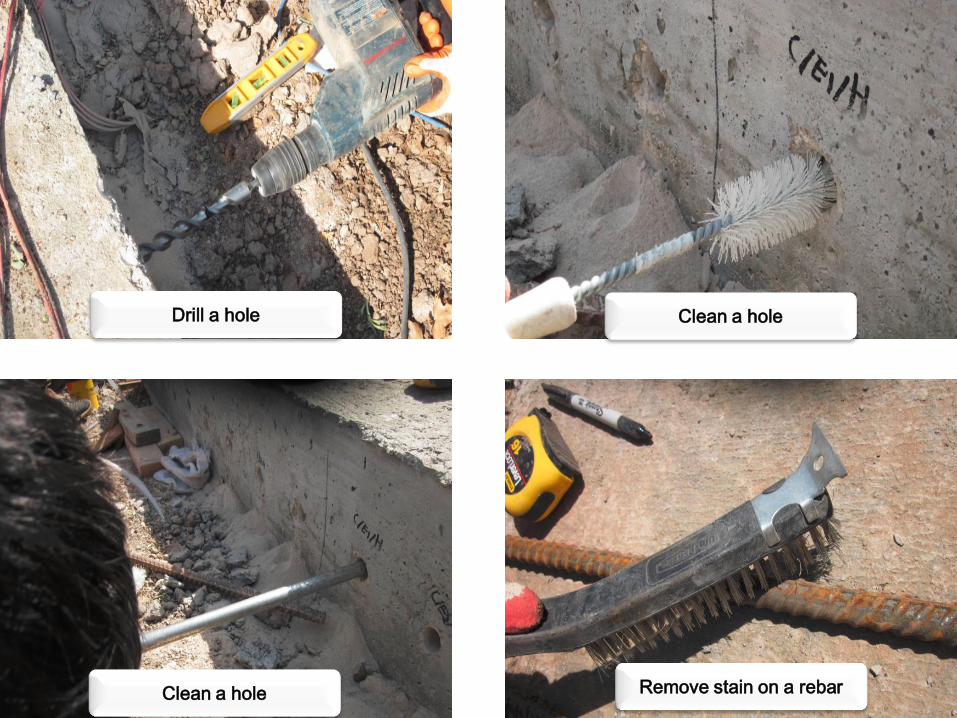
Drill a hole Clean a hole
Clean a hole Remove stain on a rebar
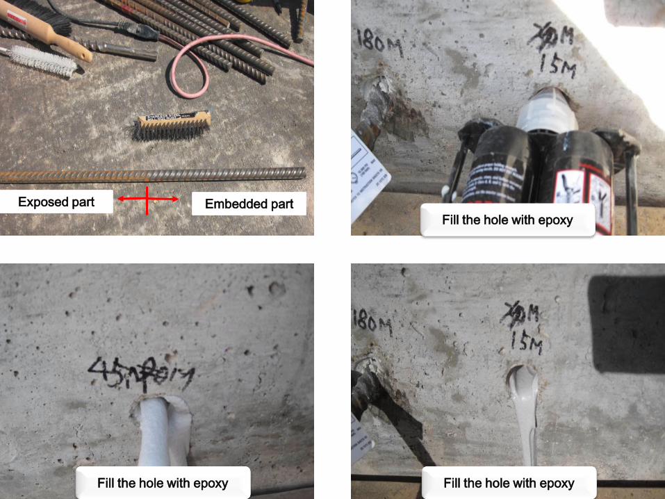
Embedded part Exposed part
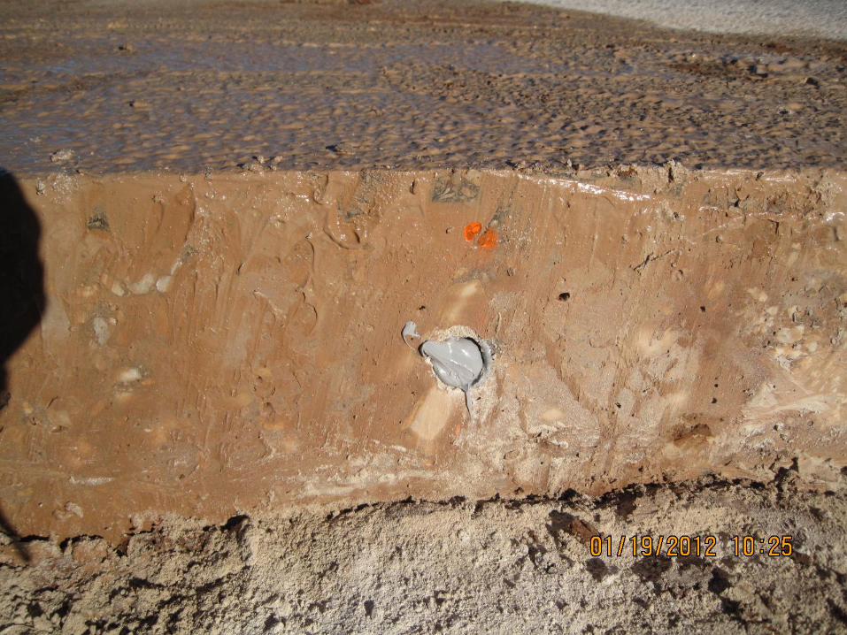
Fill the hole with epoxy
Fill the hole with epoxy Fill the hole with epoxy
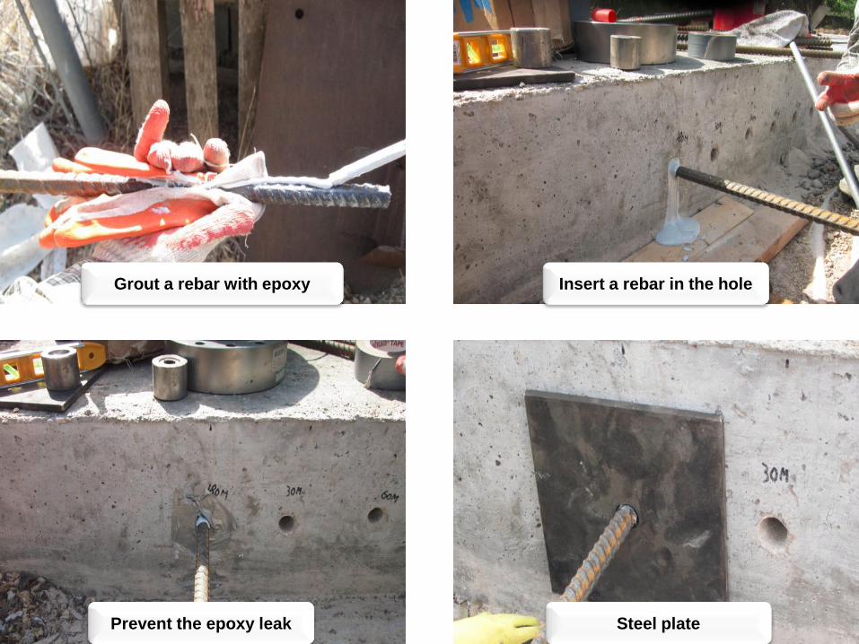
Insert a rebar in the hole Grout a rebar with epoxy
Prevent the epoxy leak Steel plate
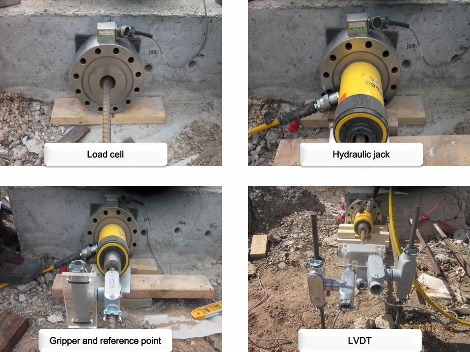
Load cell Hydraulic jack
Gripper and reference point LVDT
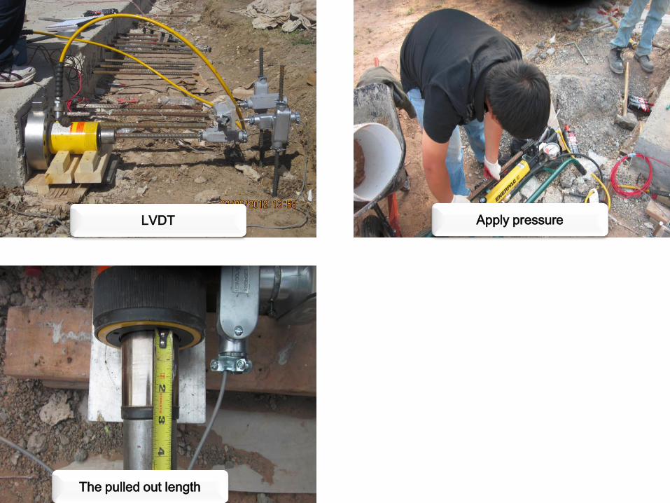
Apply pressure
The pulled out length
LVDT
Preliminary test
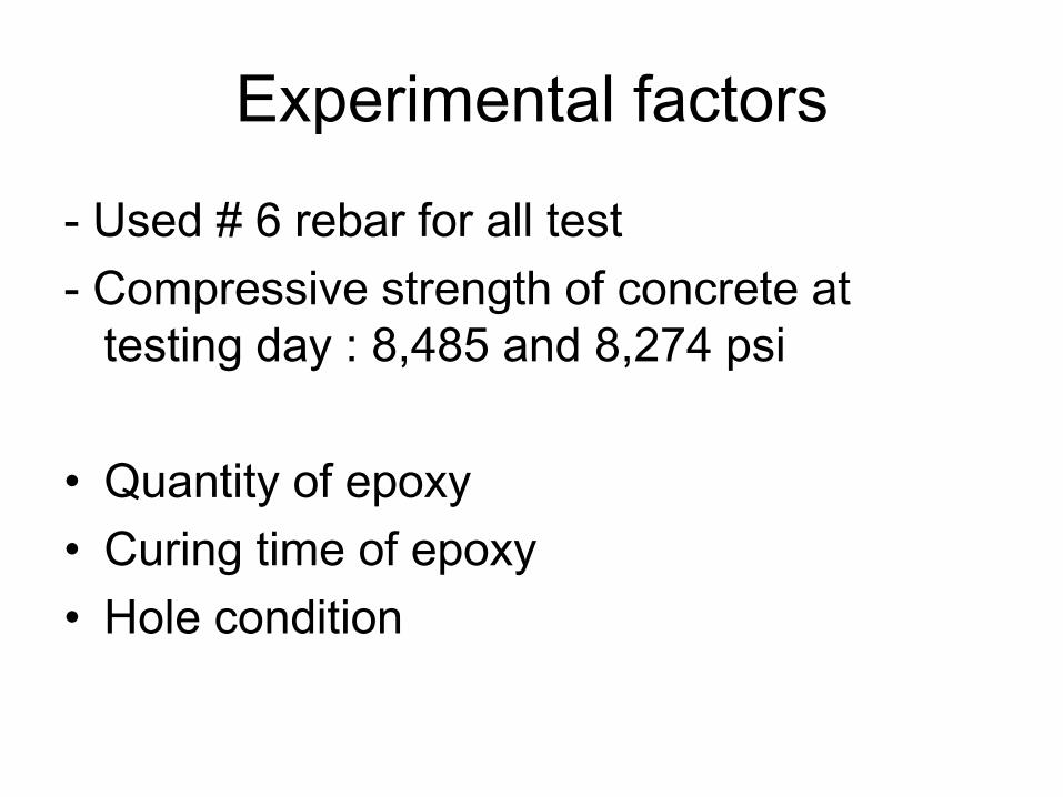
Experimental factors
- Used # 6 rebar for all test
- Compressive strength of concrete at
testing day : 8,485 and 8,274 psi
• Quantity of epoxy
• Curing time of epoxy
• Hole condition
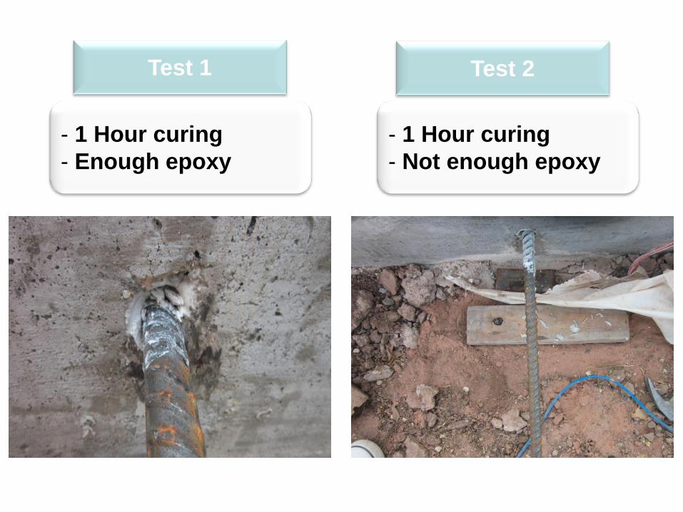
Test 2
- 1 Hour curing
- Enough epoxy
Test 1
- 1 Hour curing
- Not enough epoxy
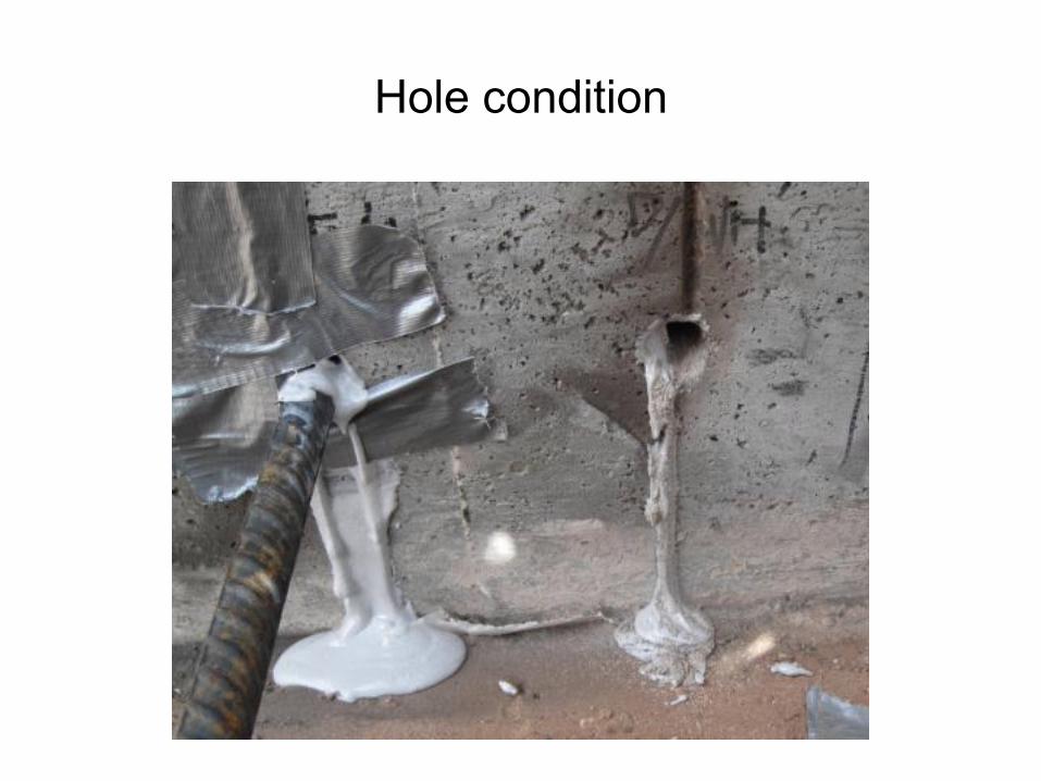
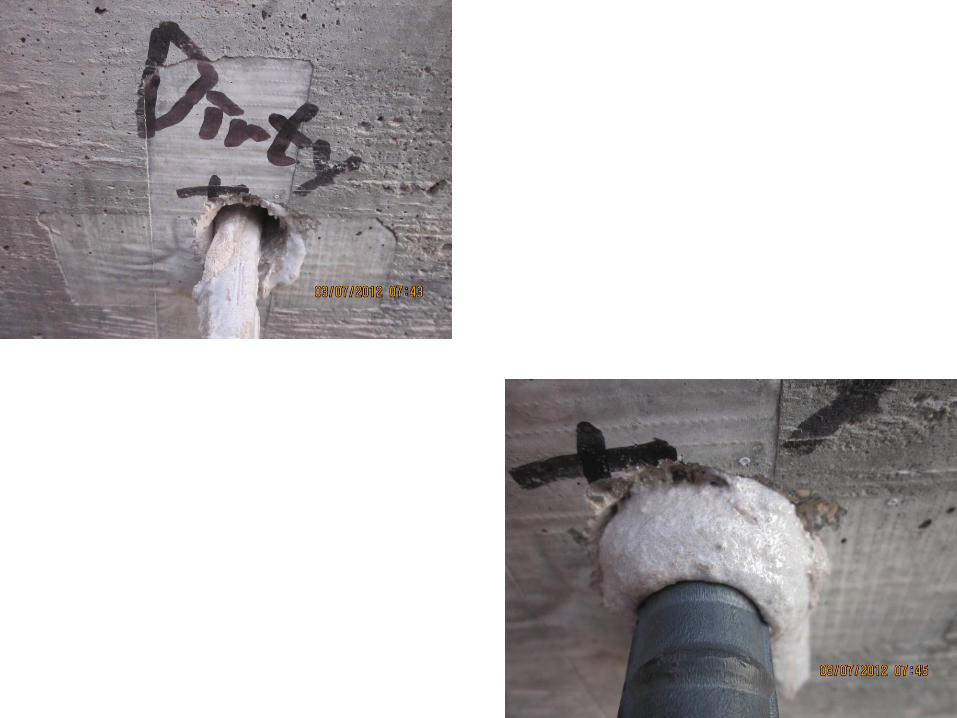
Hole condition
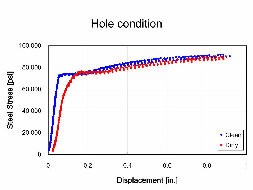
0
20,000
40,000
60,000
80,000
100,000
0 0.2 0.4 0.6 0.8 1
Displacement [in.]
Ste
el S
tre
ss [
psi]
Clean
Dirty
Hole condition

Main test
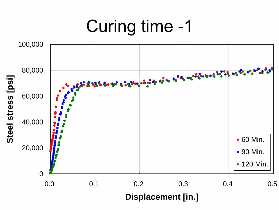
Curing time -1
0
20,000
40,000
60,000
80,000
100,000
0.0 0.1 0.2 0.3 0.4 0.5
Displacement [in.]
Ste
el
str
es
s [
ps
i]
60 Min.
90 Min.
120 Min.
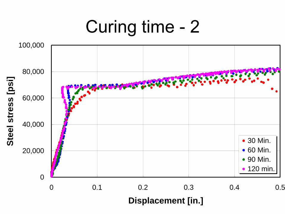
Curing time - 2
0
20,000
40,000
60,000
80,000
100,000
0 0.1 0.2 0.3 0.4 0.5
Displacement [in.]
Ste
el
str
es
s [
ps
i]
30 Min.
60 Min.
90 Min.
120 min.
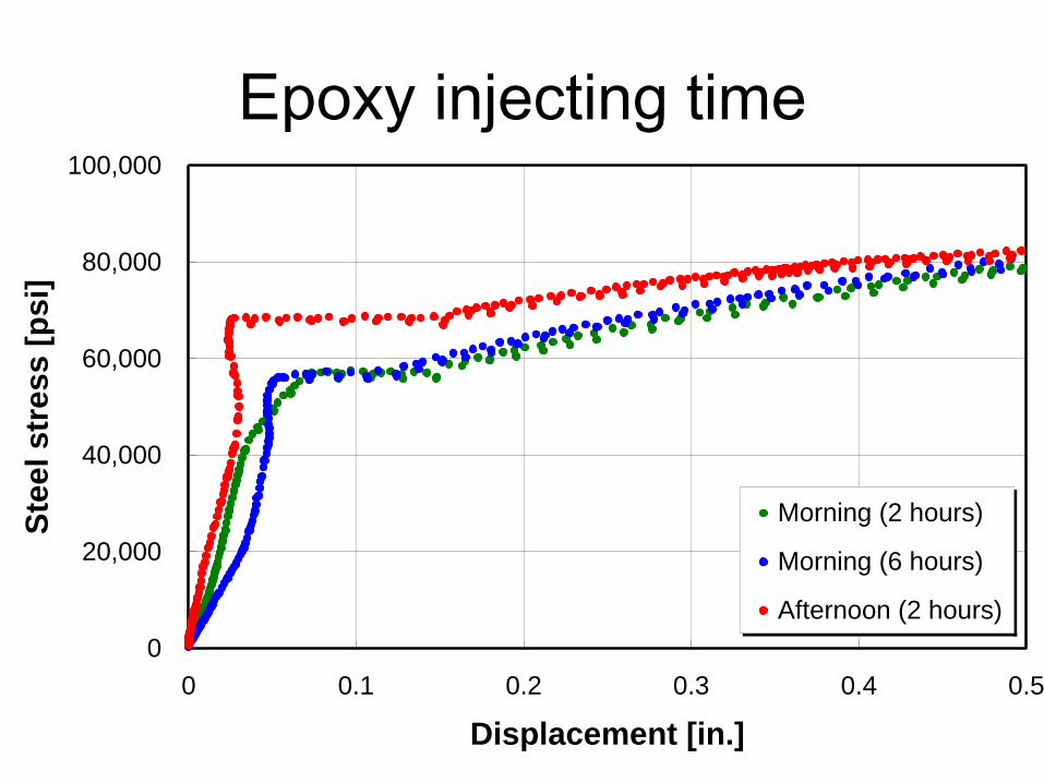
Epoxy injecting time
0
20,000
40,000
60,000
80,000
100,000
0 0.1 0.2 0.3 0.4 0.5
Displacement [in.]
Ste
el
str
es
s [
ps
i]
Morning (2 hours)
Morning (6 hours)
Afternoon (2 hours)
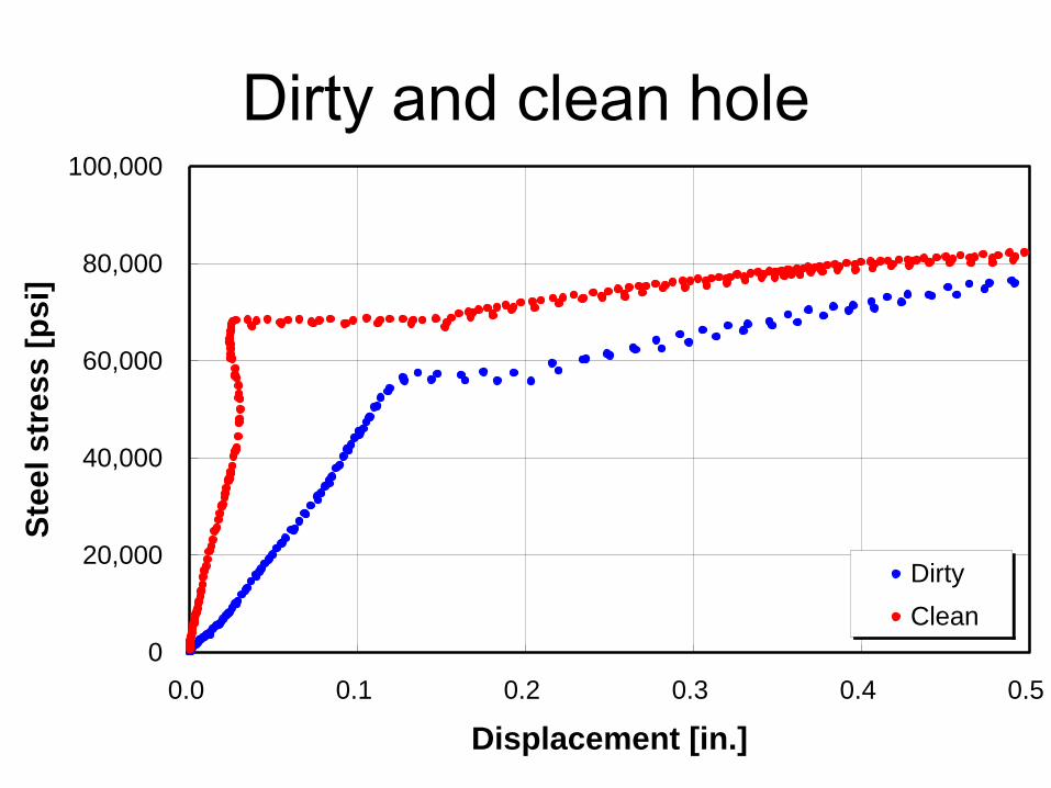
Dirty and clean hole
0
20,000
40,000
60,000
80,000
100,000
0.0 0.1 0.2 0.3 0.4 0.5
Displacement [in.]
Ste
el
str
es
s [
ps
i]
Dirty
Clean
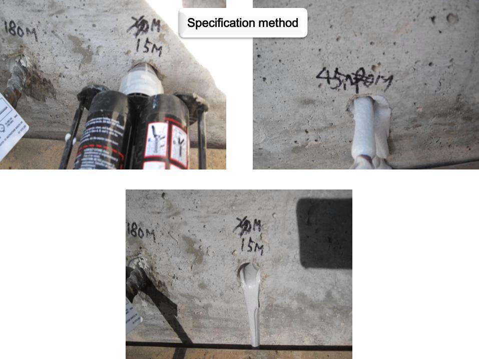
Specification method
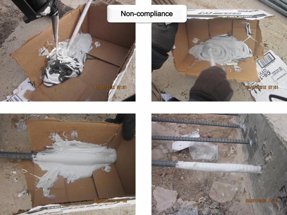
Non-compliance
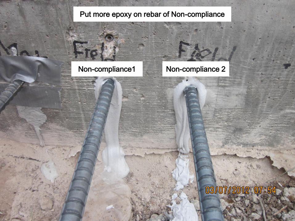
Put more epoxy on rebar of Non-compliance
Non-compliance1 Non-compliance 2
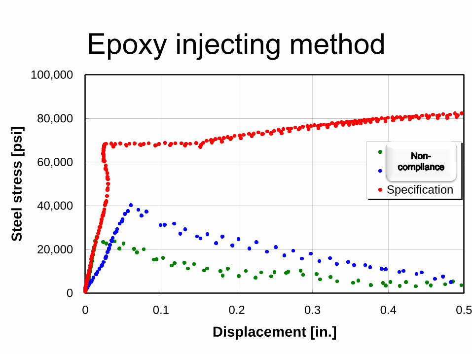
Epoxy injecting method
0
20,000
40,000
60,000
80,000
100,000
0 0.1 0.2 0.3 0.4 0.5
Displacement [in.]
Ste
el
str
es
s [
ps
i]
Field 1
Field 2
Specification
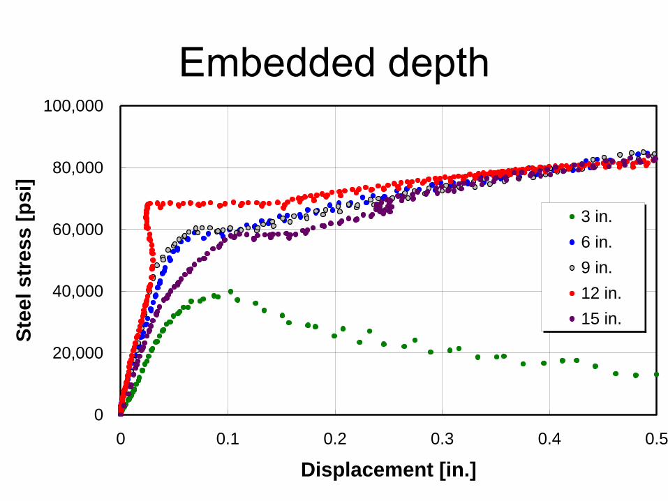
Embedded depth
0
20,000
40,000
60,000
80,000
100,000
0 0.1 0.2 0.3 0.4 0.5
Displacement [in.]
Ste
el
str
es
s [
ps
i]
3 in.
6 in.
9 in.
12 in.
15 in.
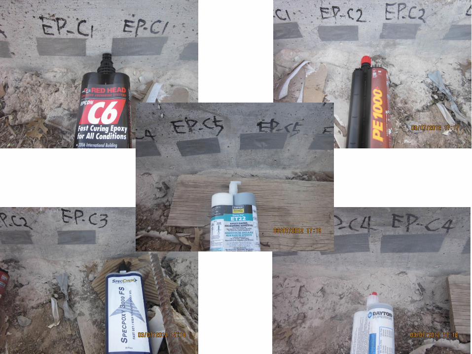
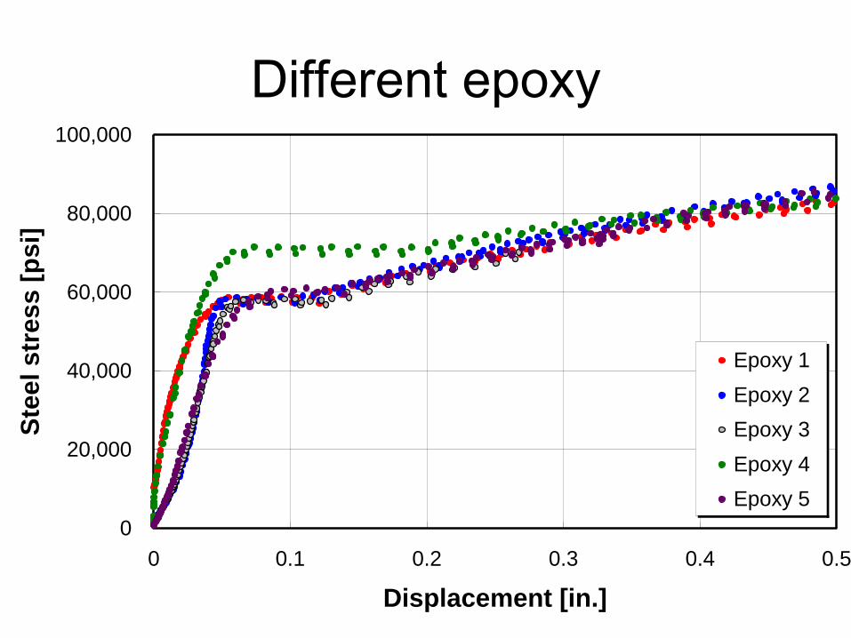
Different epoxy
0
20,000
40,000
60,000
80,000
100,000
0 0.1 0.2 0.3 0.4 0.5
Displacement [in.]
Ste
el
str
es
s [
ps
i]
Epoxy 1
Epoxy 2
Epoxy 3
Epoxy 4
Epoxy 5
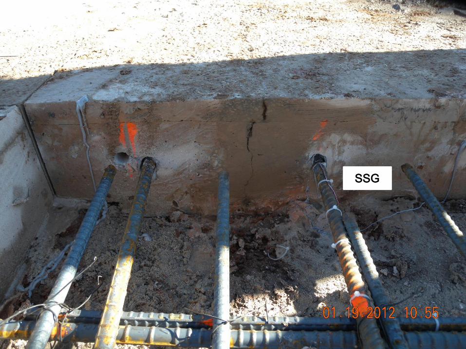
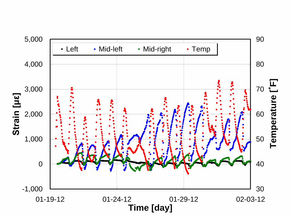
SSG
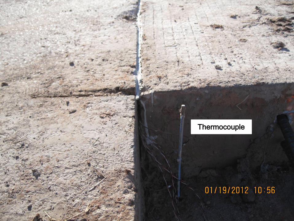
Thermocouple
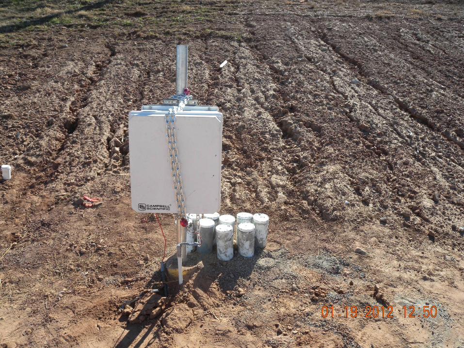

Gage analysis
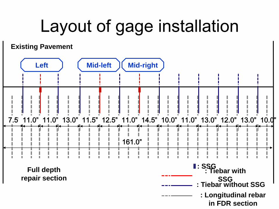
Existing Pavement
Full depth
repair section
Left Mid-left Mid-right
: SSG
7.5” 11.0” 11.0” 13.0” 11.5” 12.5” 11.0” 14.5” 10.0” 11.0” 13.0” 12.0” 13.0” 10.0”
161.0”
: Tiebar with
SSG : Tiebar without SSG
: Longitudinal rebar
in FDR section
Layout of gage installation

-1,000
0
1,000
2,000
3,000
4,000
5,000
01-19-12 01-24-12 01-29-12 02-03-12
Time [day]
Str
ain
[μ
ε]
30
40
50
60
70
80
90
Te
mp
era
ture
[˚ F
]
Left Mid-left Mid-right Temp
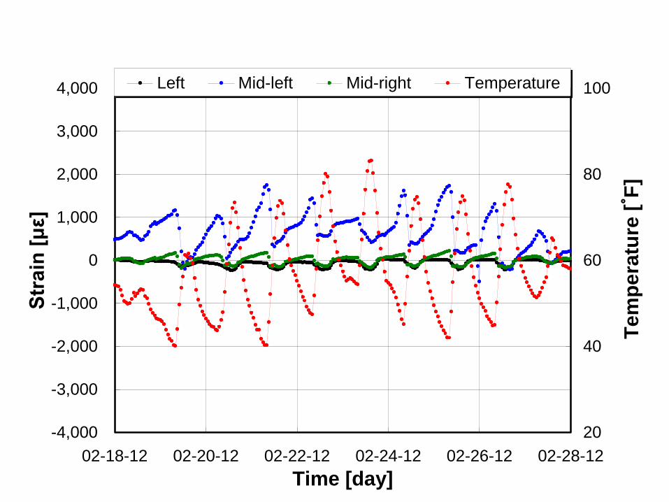
-4,000
-3,000
-2,000
-1,000
0
1,000
2,000
3,000
4,000
02-18-12 02-20-12 02-22-12 02-24-12 02-26-12 02-28-12
Time [day]
Str
ain
[μ
ε]
20
40
60
80
100
Te
mp
era
ture
[˚ F
]
Left Mid-left Mid-right Temperature
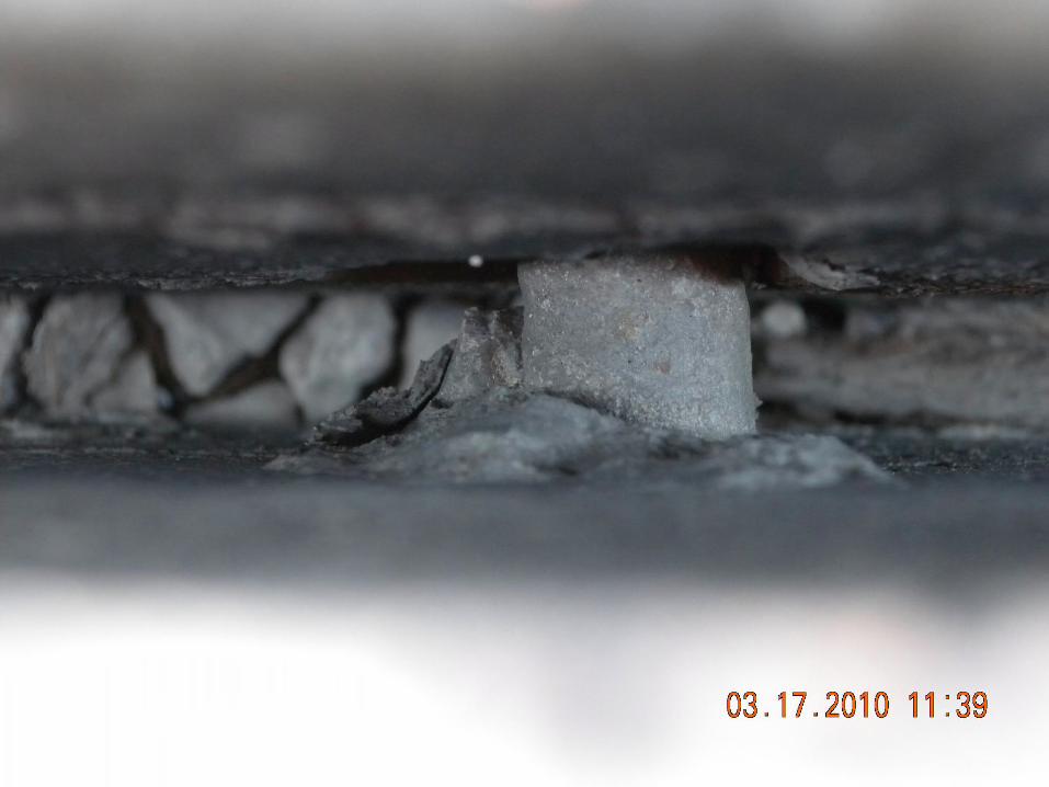
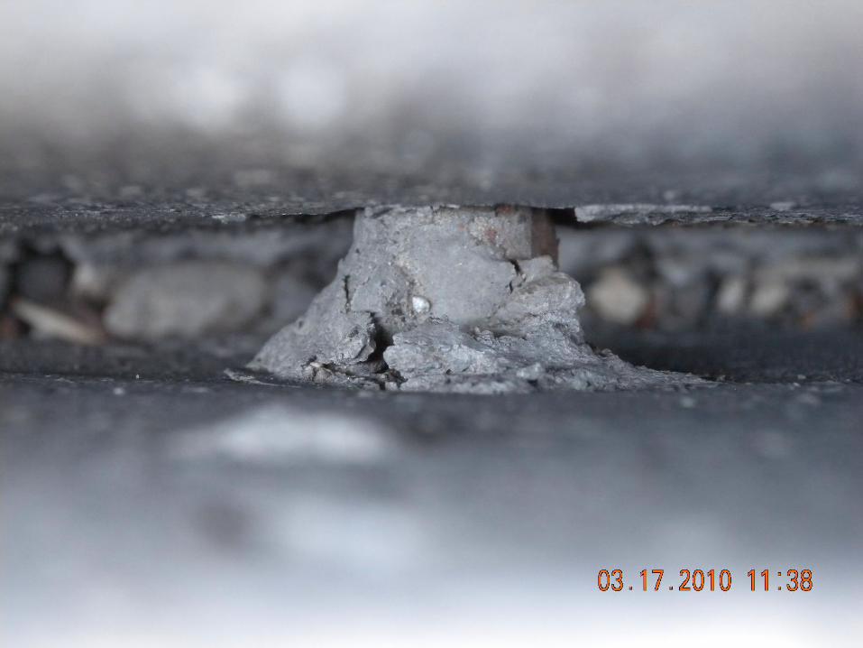
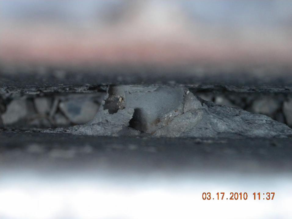
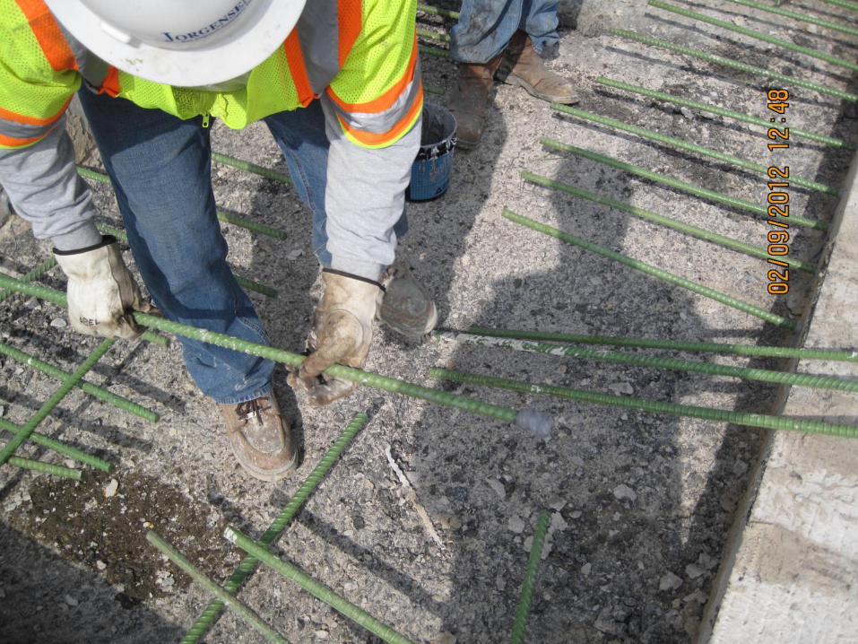
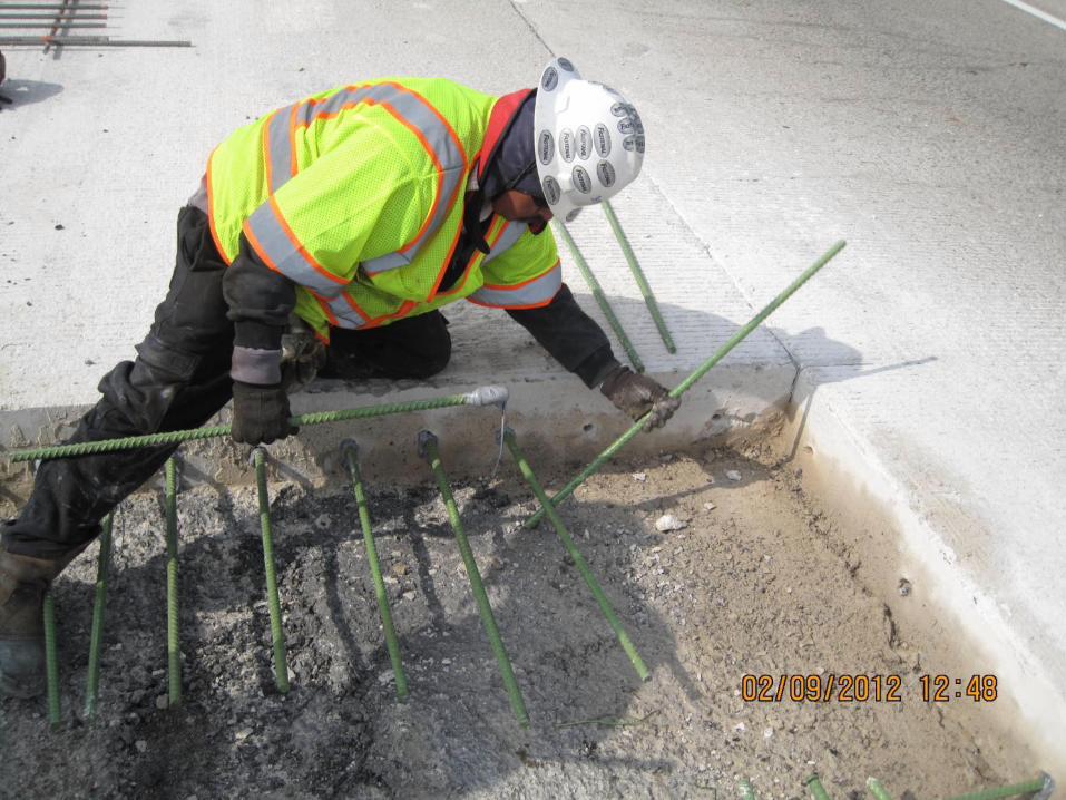
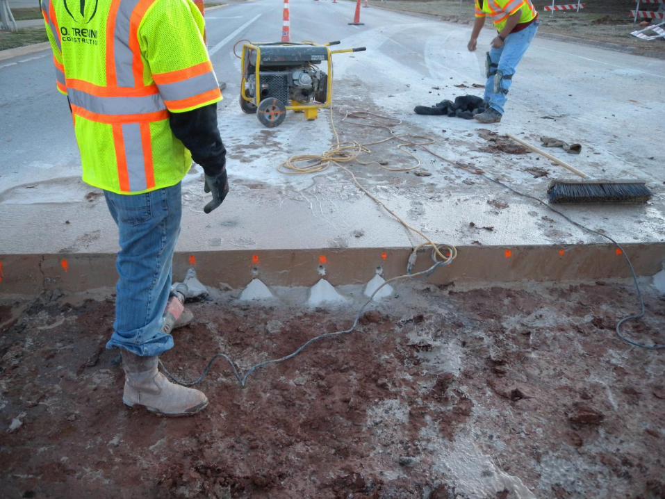
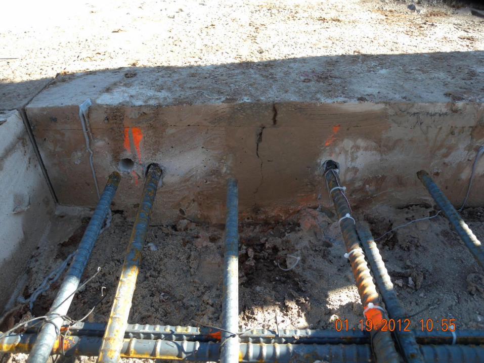
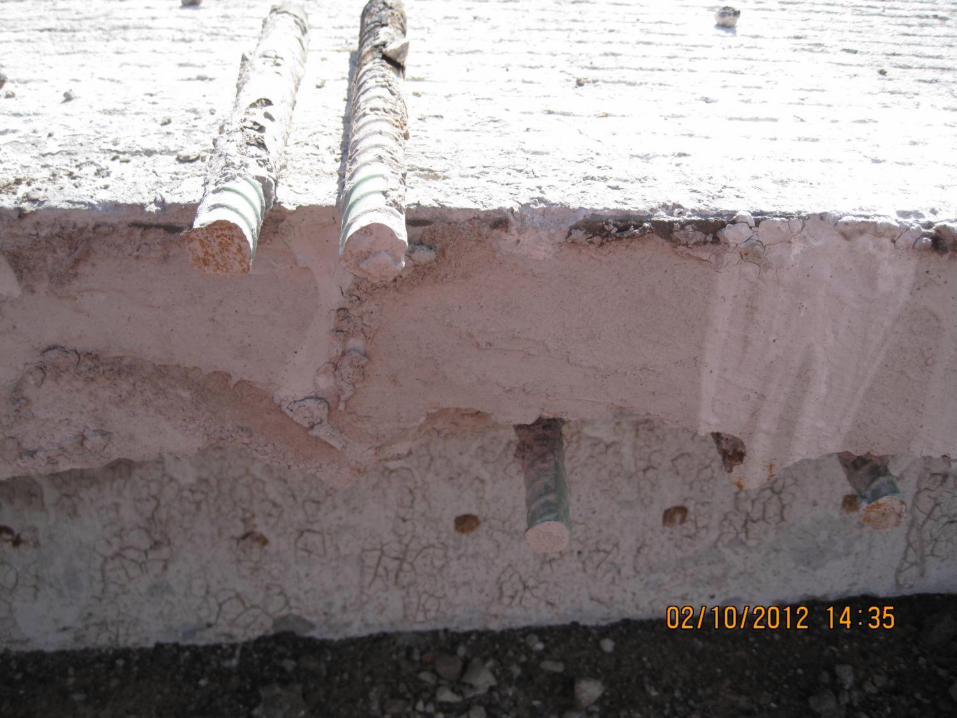
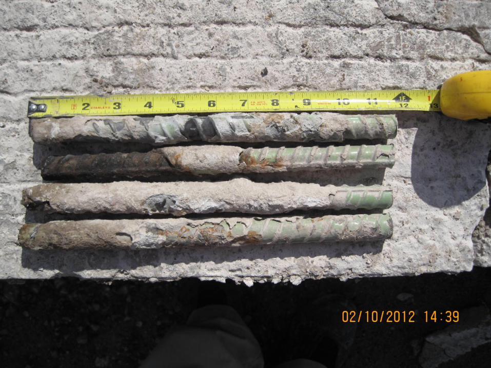
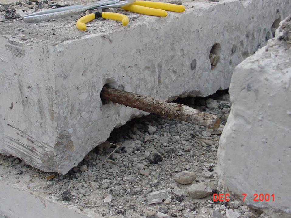
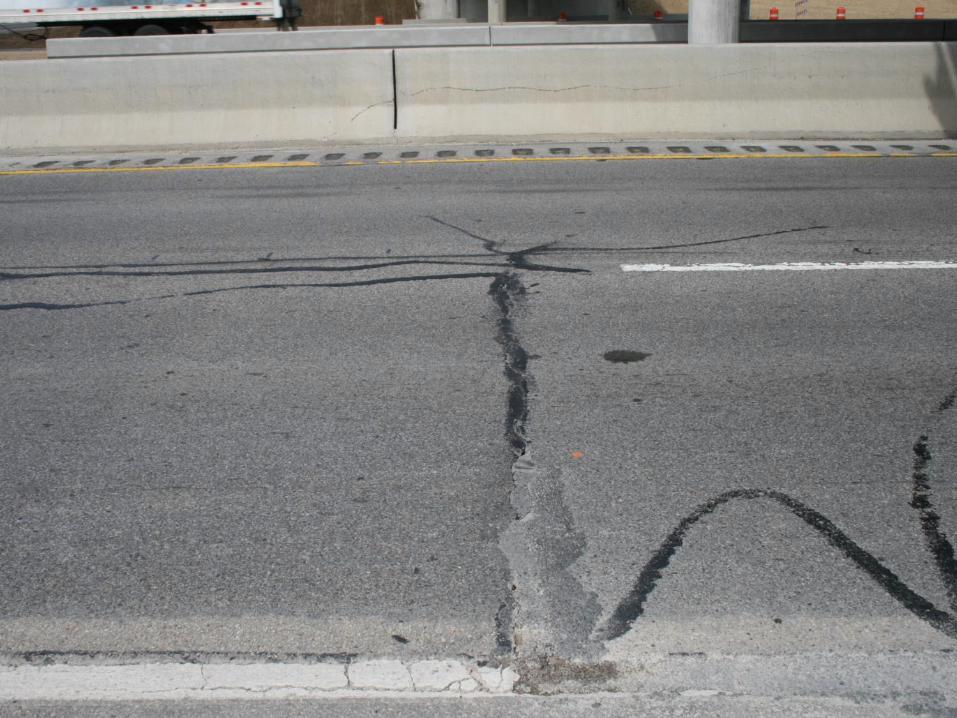
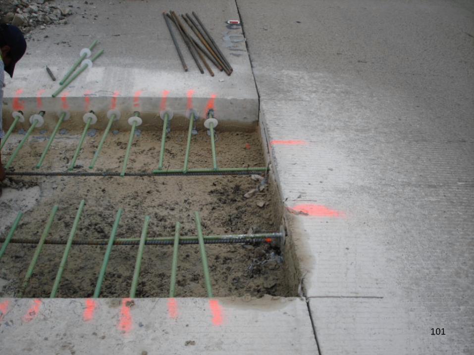
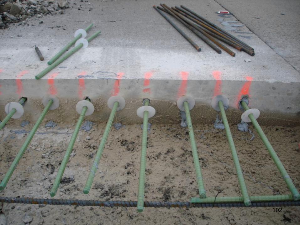
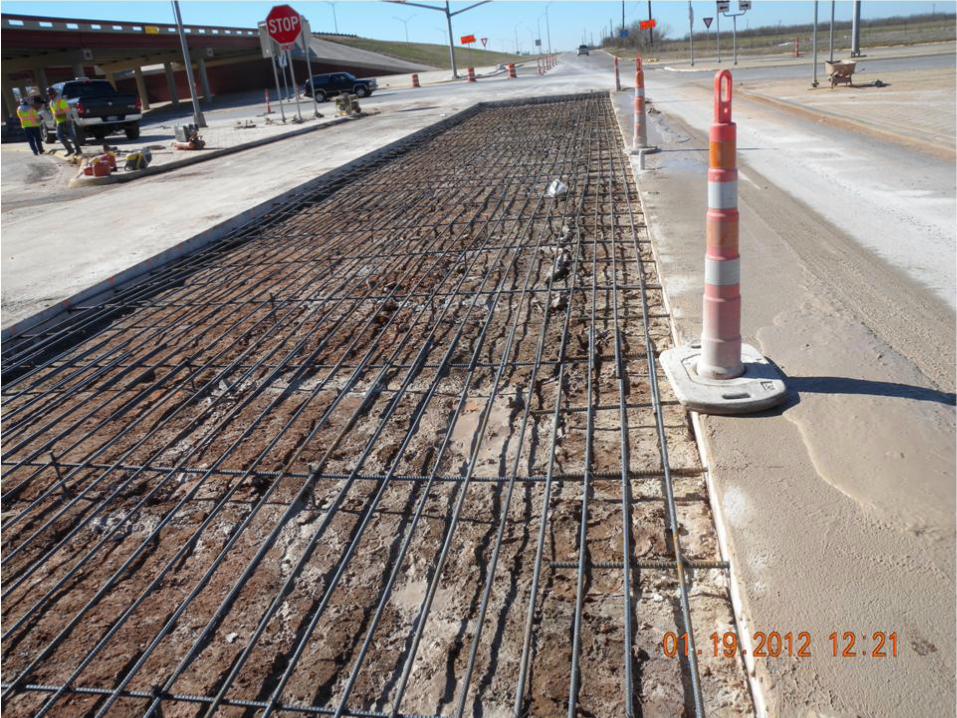
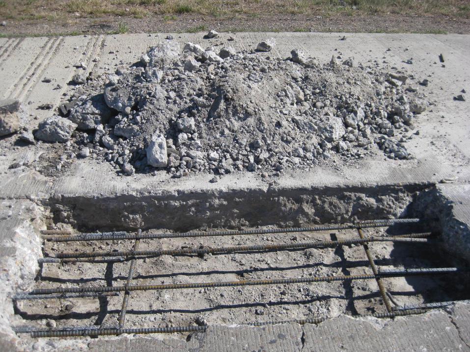
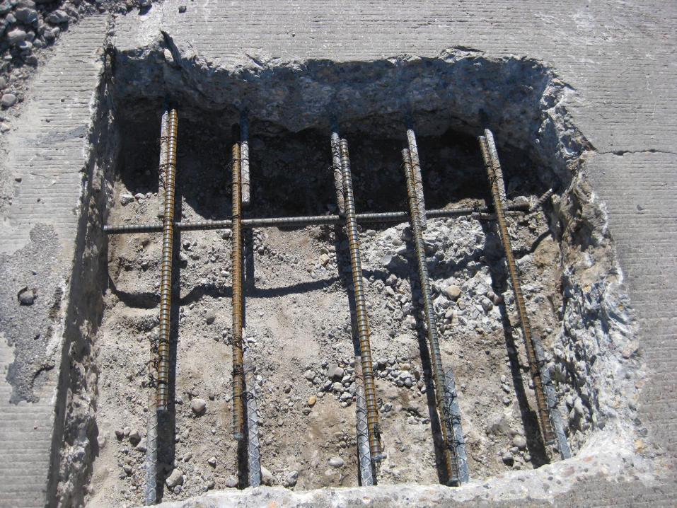
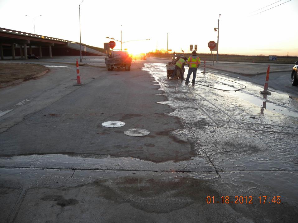
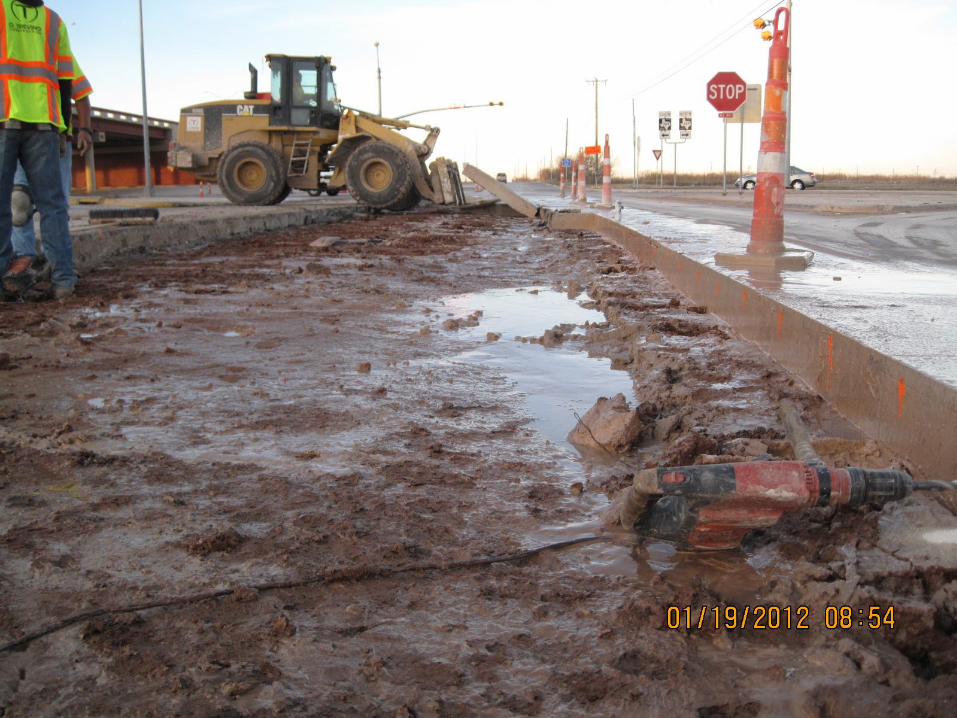
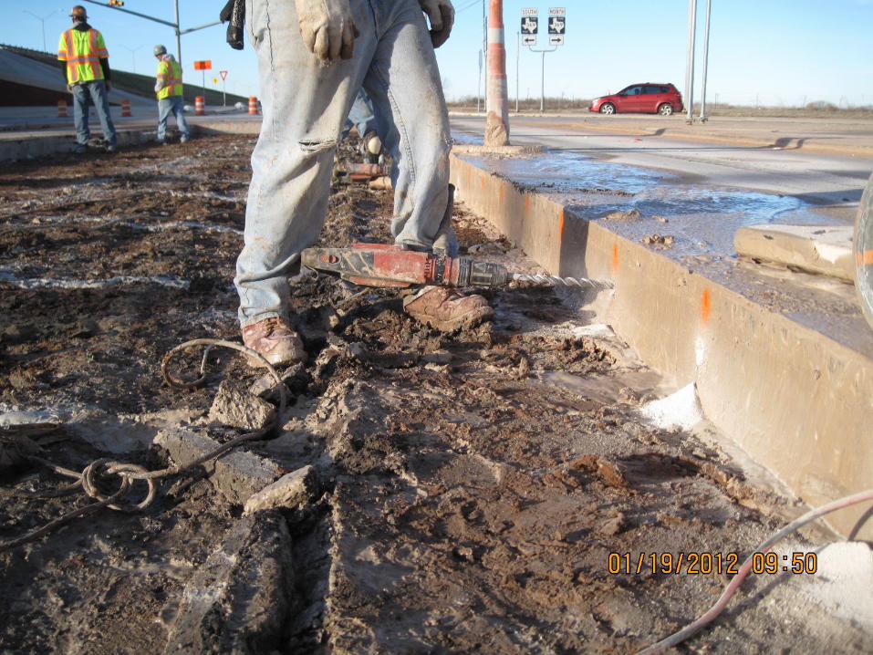
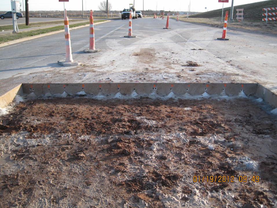
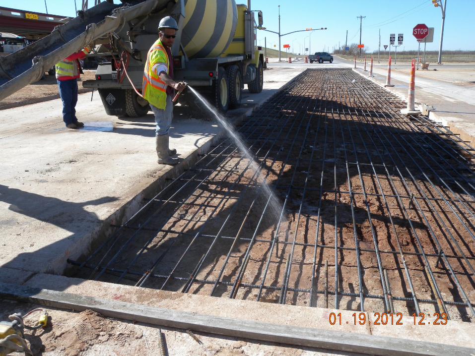
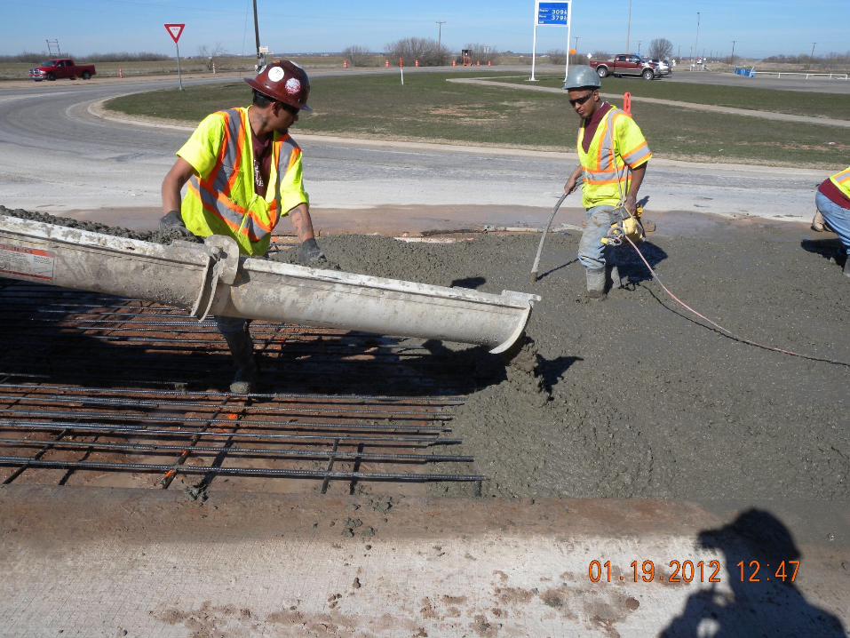
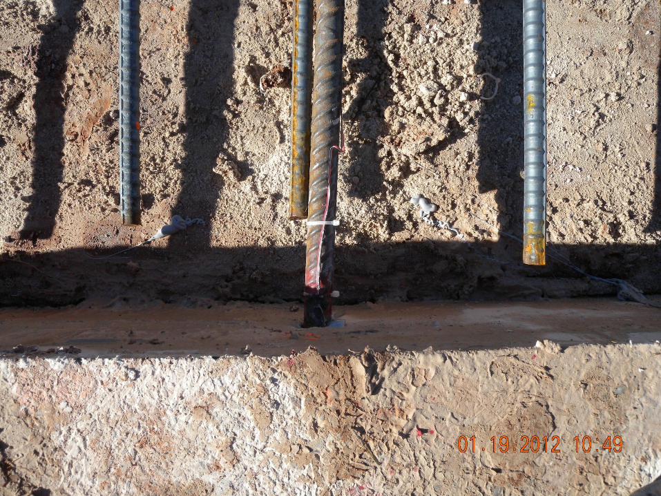
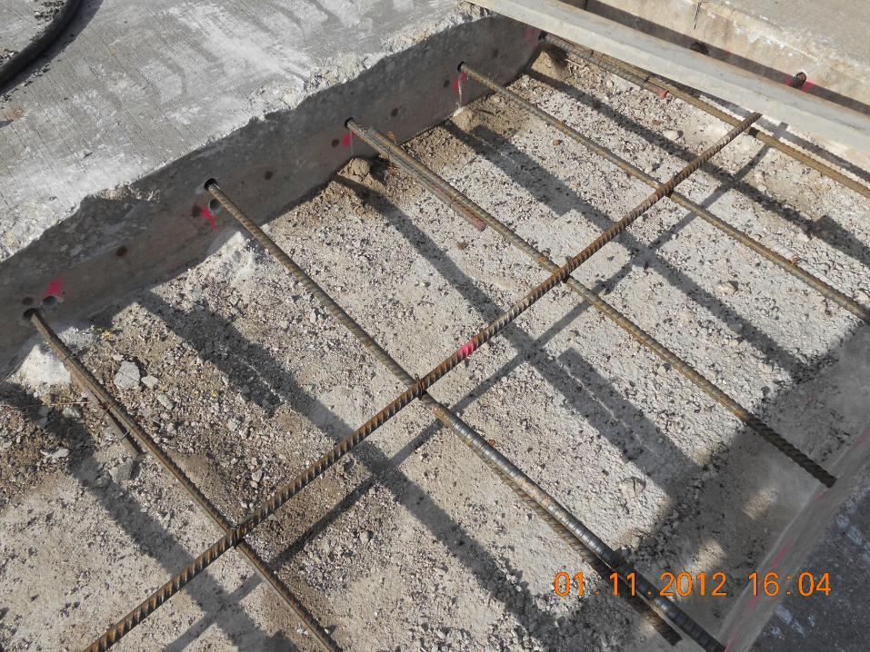
Other Issues with FDRs
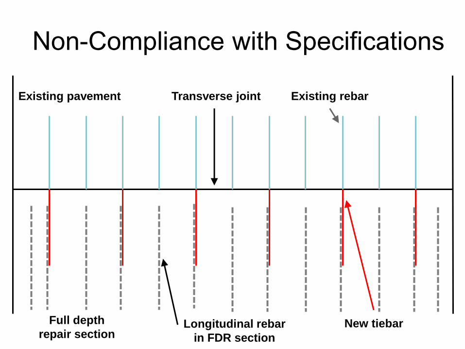
Non-Compliance with Specifications
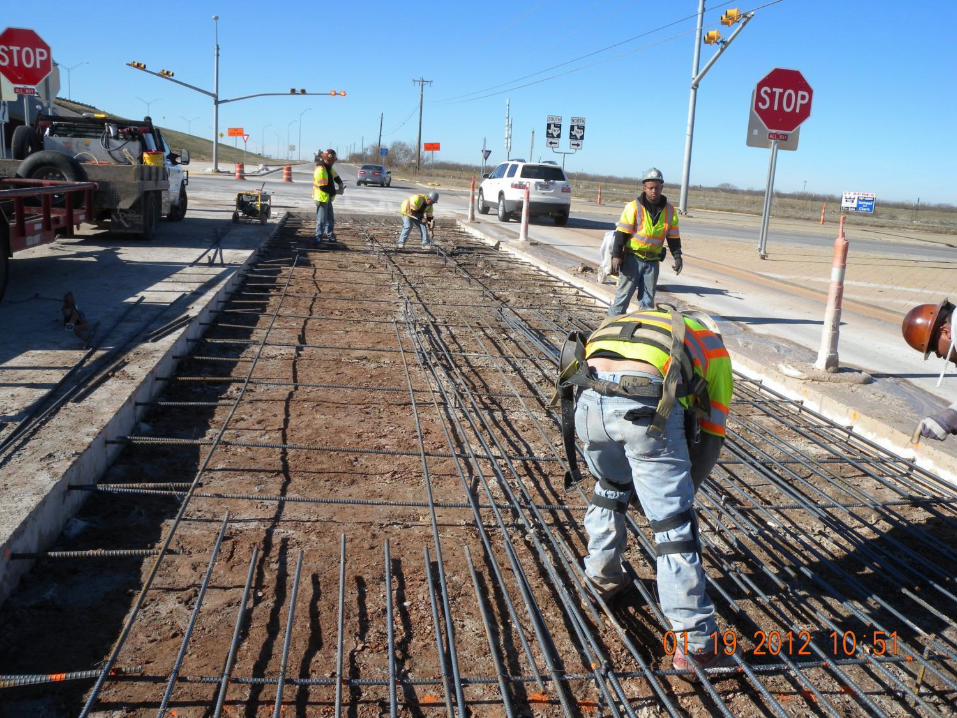
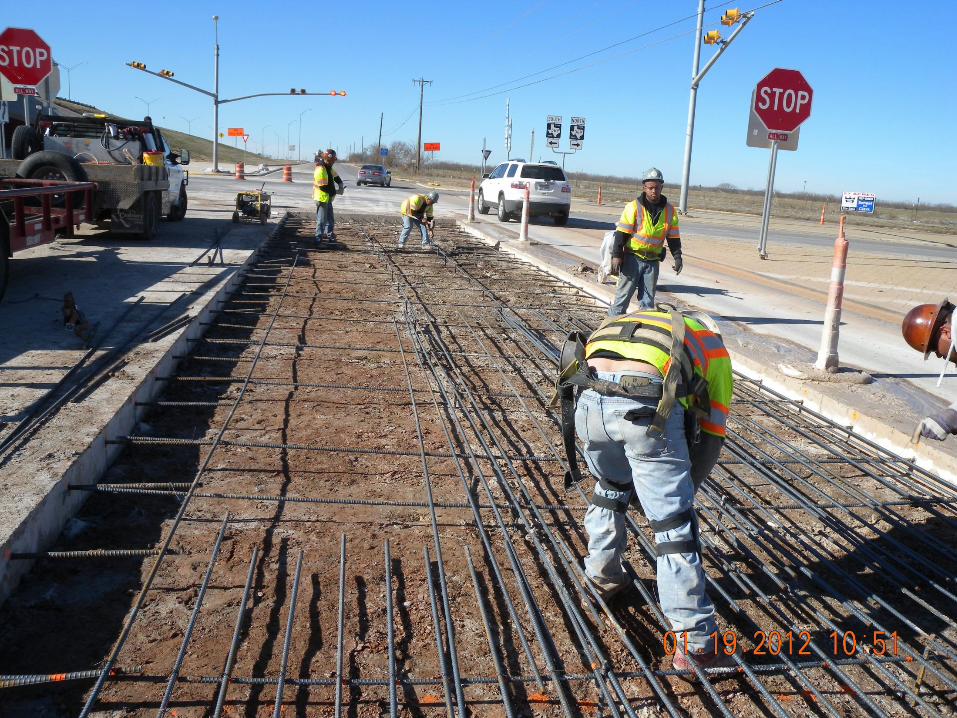
Existing pavement
Full depth
repair section
Transverse joint Existing rebar
New tiebar Longitudinal rebar
in FDR section
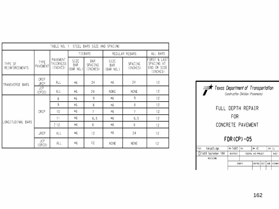
162
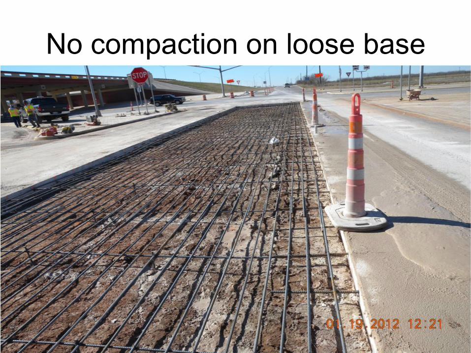
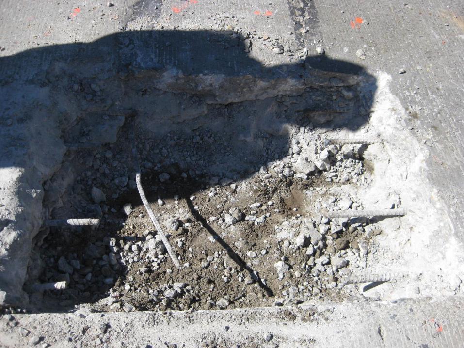
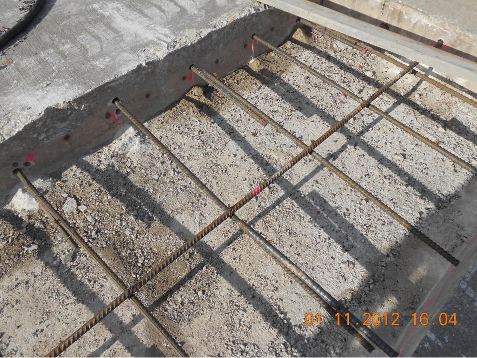
No compaction on loose base
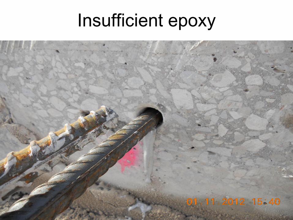
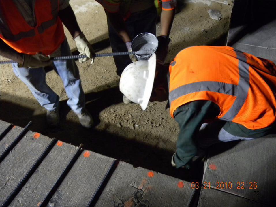
Insufficient epoxy
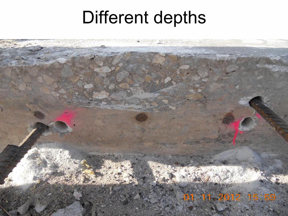
Different depths
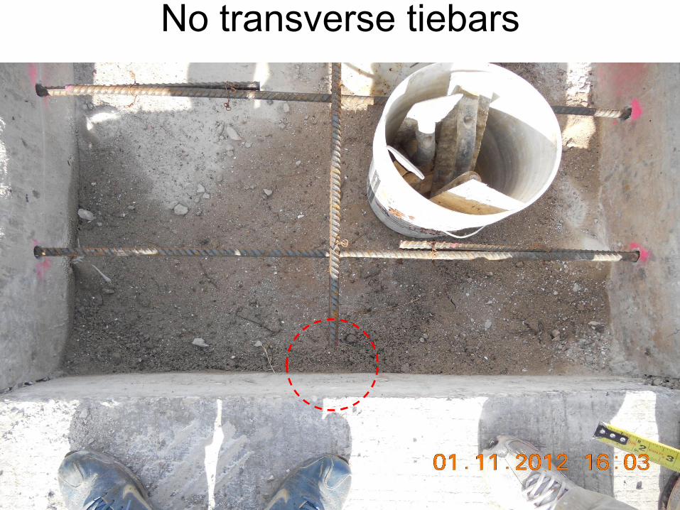
No transverse tiebars
167
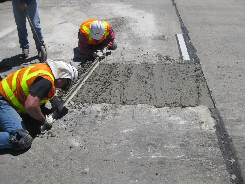
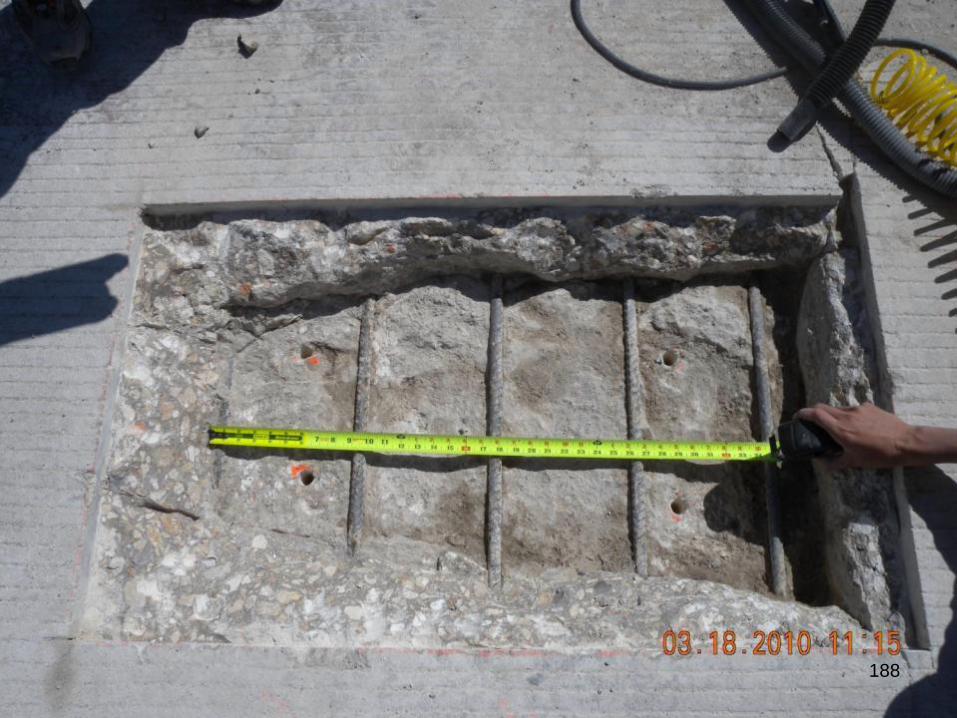
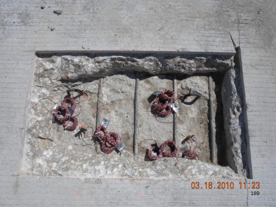
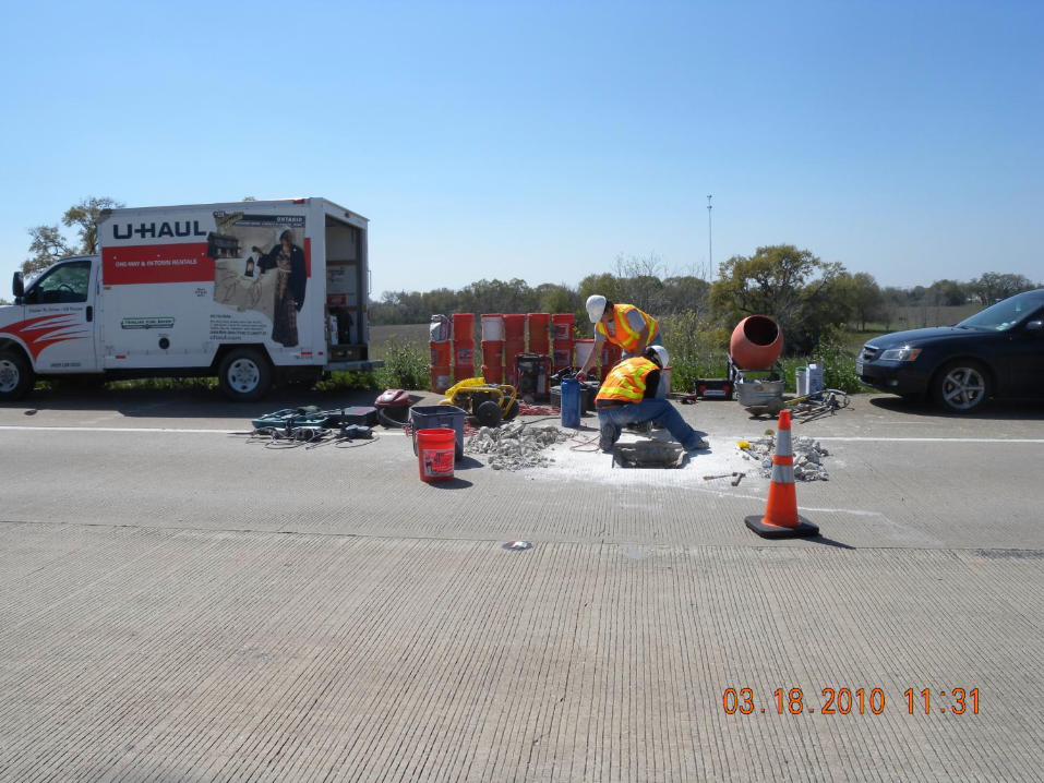
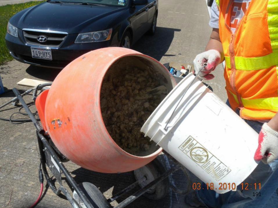
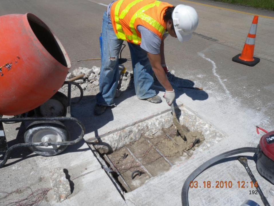
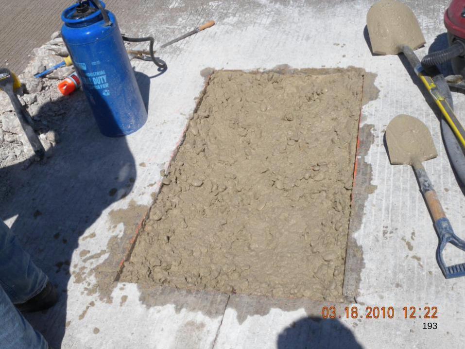
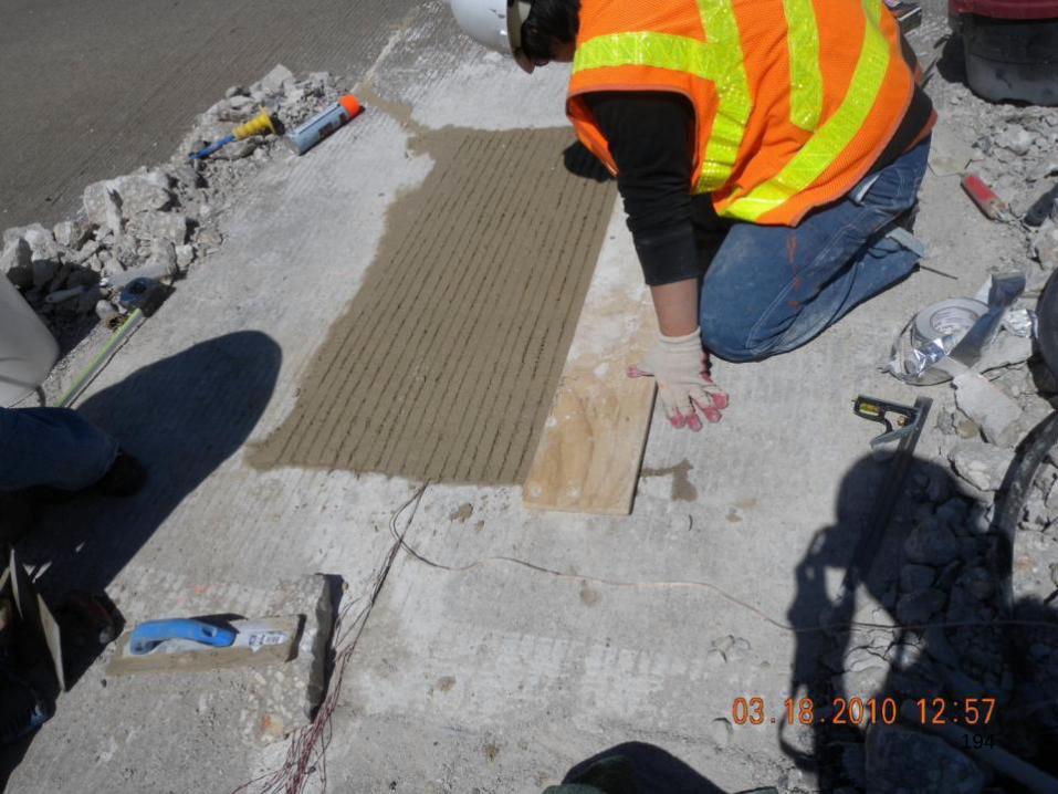
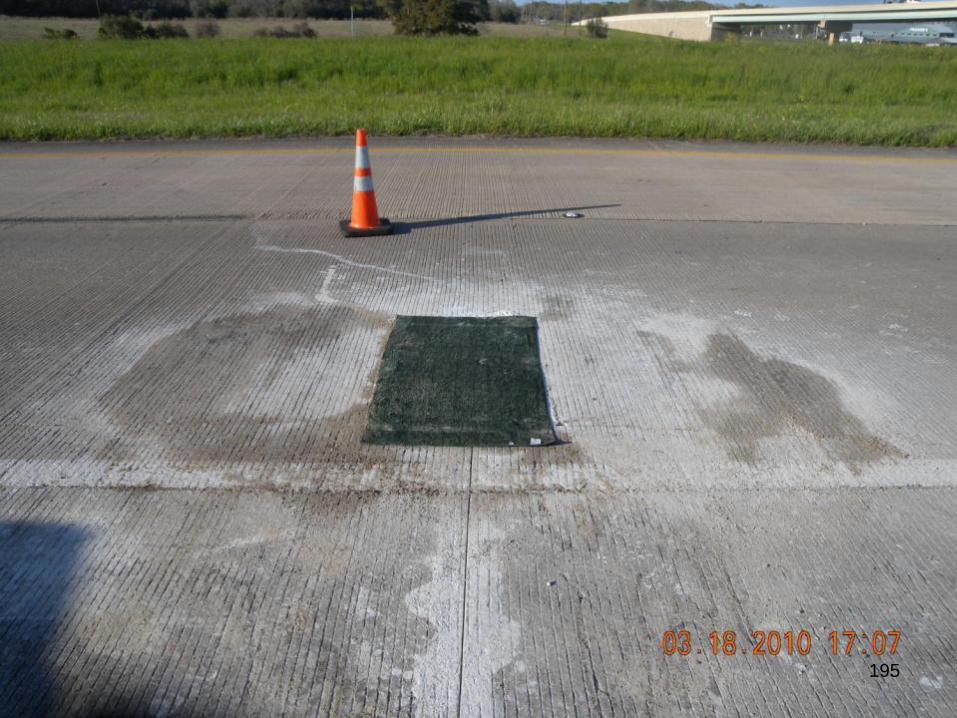
PARTIAL-DEPTH REPAIR OF
CRCP
172
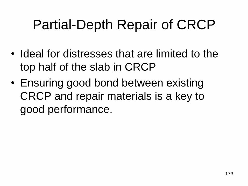
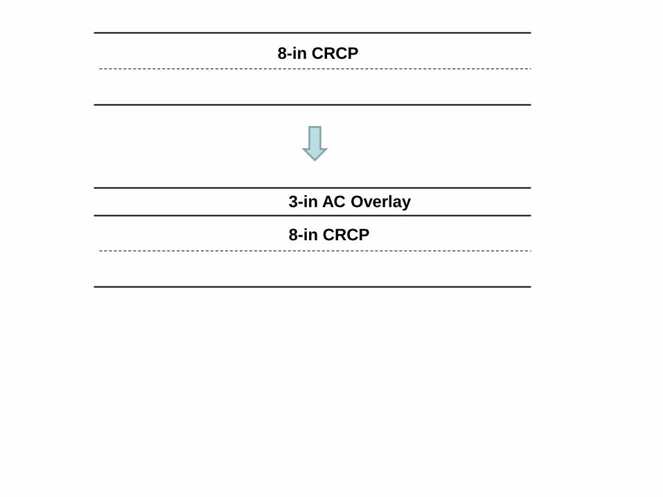
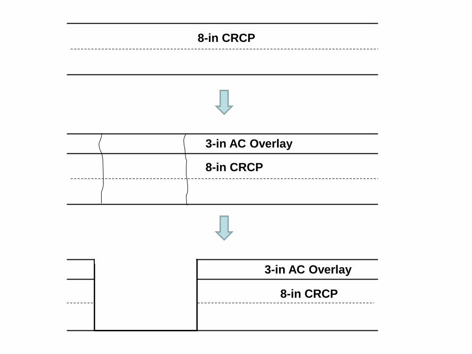
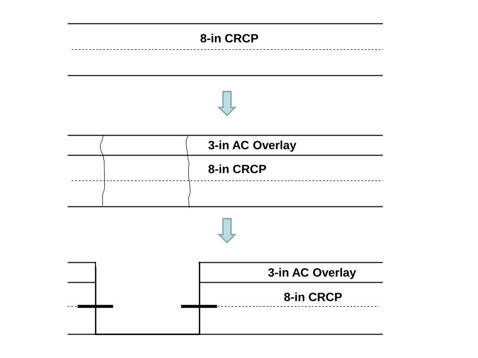
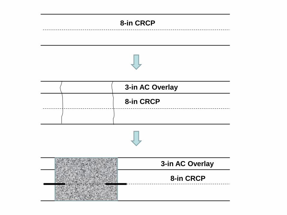
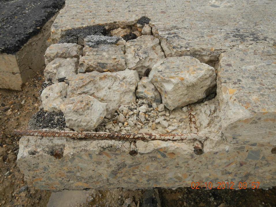
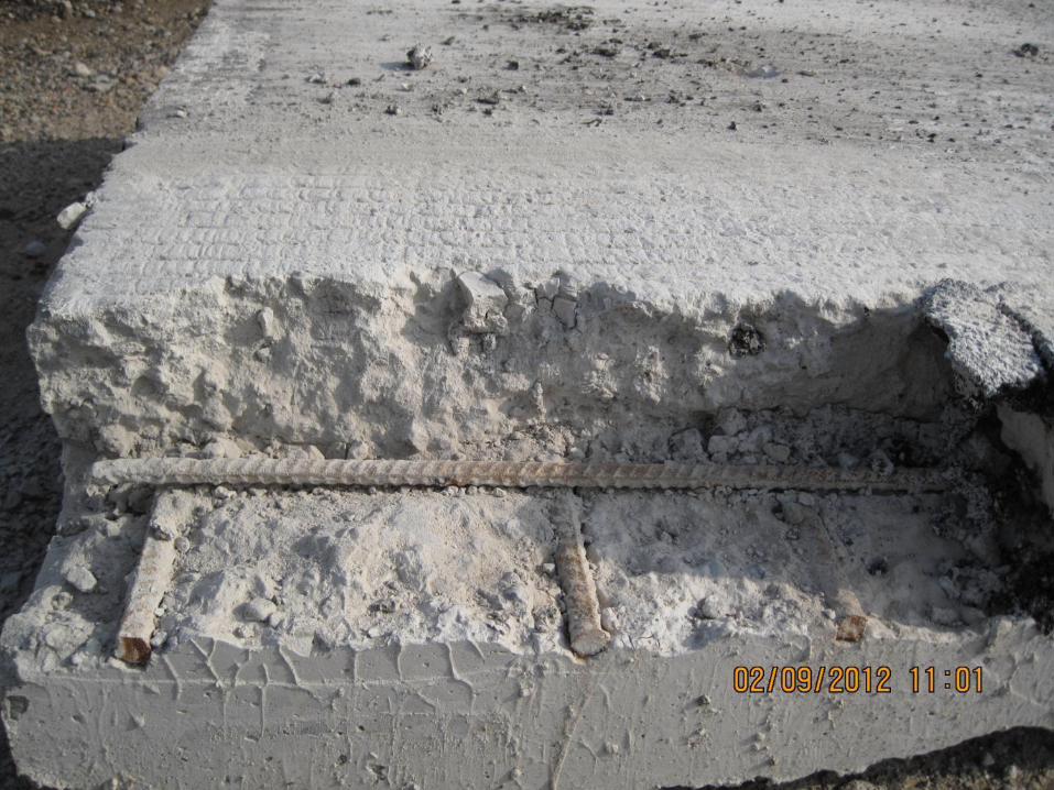
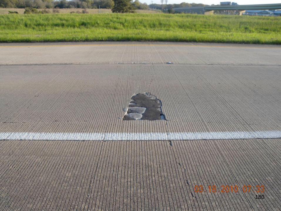
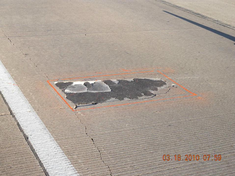
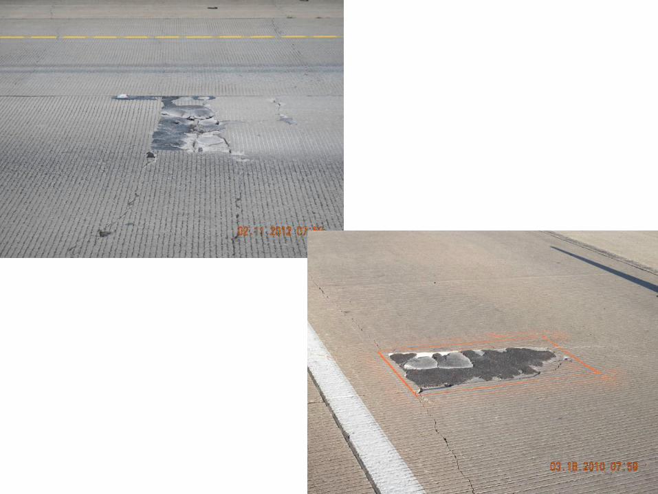
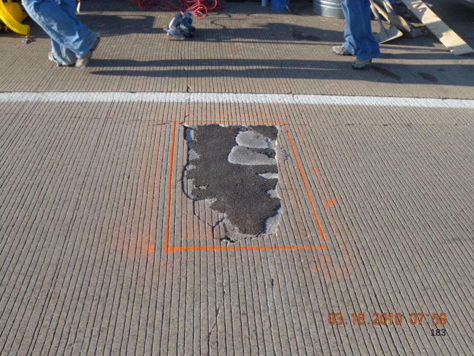
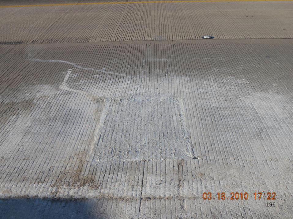
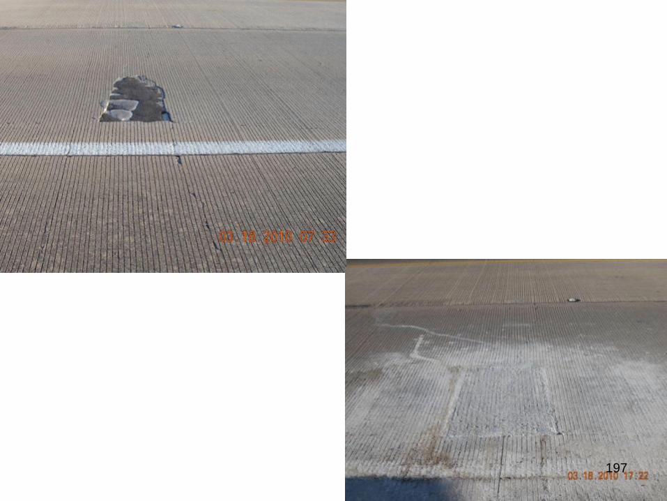
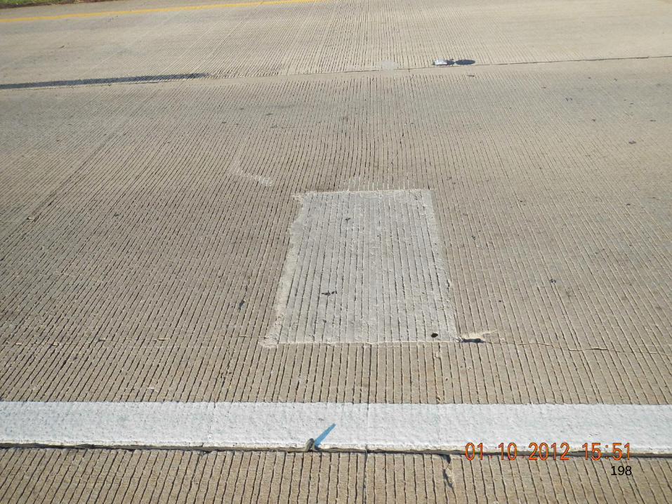
Partial-Depth Repair of CRCP
• Ideal for distresses that are limited to the
top half of the slab in CRCP
• Ensuring good bond between existing
CRCP and repair materials is a key to
good performance.
173
174
176
177
178
179
180
181
182
183
184
185
186
187
188
189
190
191
192
193
194
195
196
197
198
199
Summary
as- Full-Depth Repairs -
• Establishing solid bond in tie bars
o Spec requirements: fill holes with epoxy, minimize
drain downs using grout retention disks
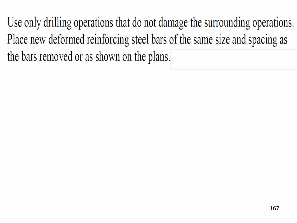
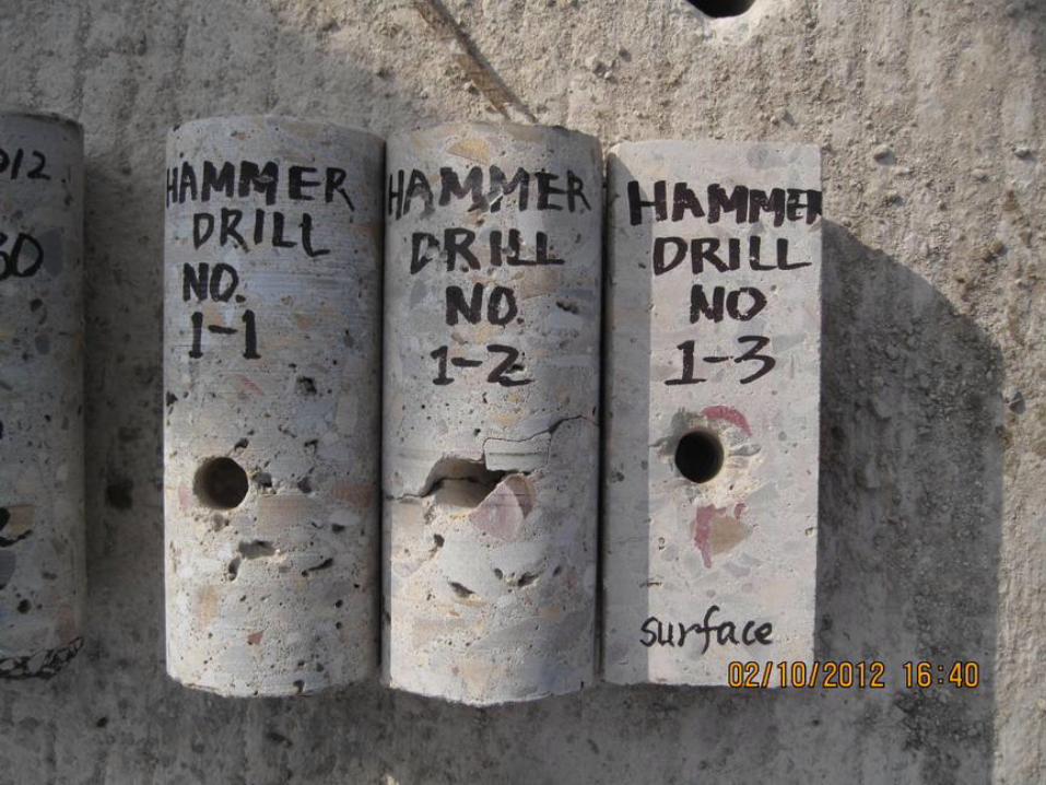
• Drilling holes
o Hammer drill, rotary drill, core drill
o At mid-depth or below the mid-depth if needed, but
not above
• Tie bar or longitudinal bar spacing
o Should be the same as in the existing CRCP.
200
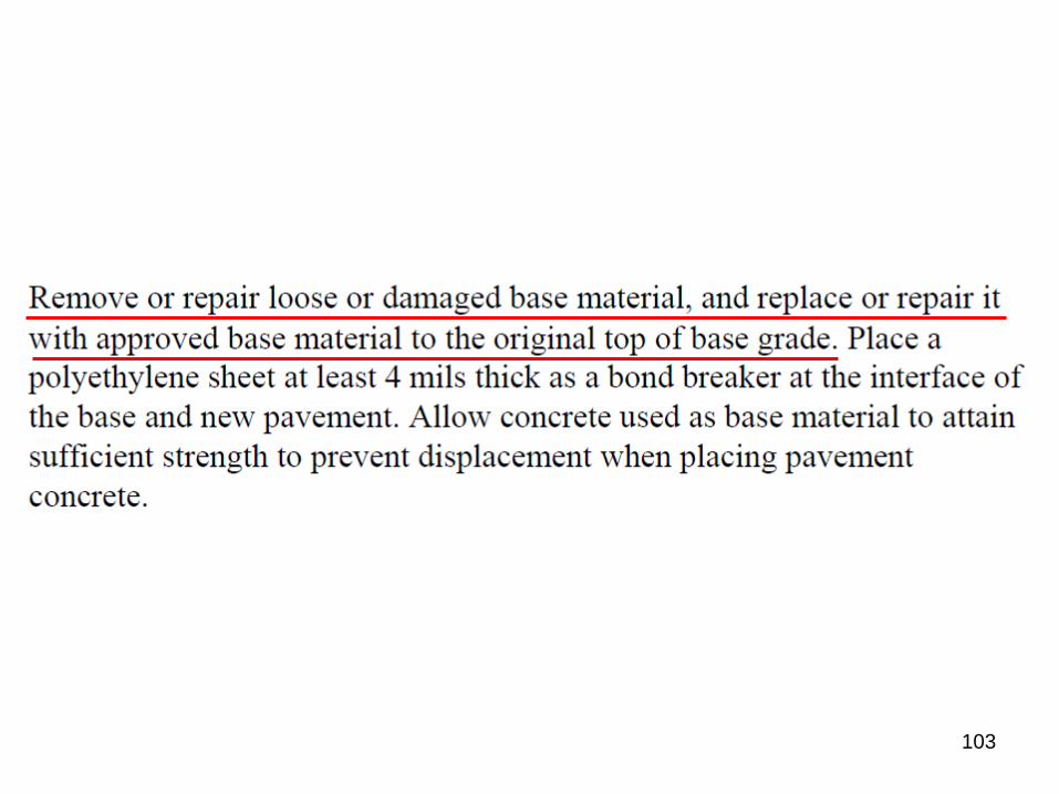
Summary
as- Full-Depth Repairs -
• Establishing solid base
o Spec requirements: remove loose materials & replace
with concrete
201
Summary
as- Partial-Depth Repairs -
• Good candidate for distresses for US 75 and IH 30
o Still under evaluations
• Establishing good bond bet’n old and new concrete
o Hook bars
• Other good concreting practices
202