Embed Size (px)
Citation preview
Full HD CCTV Armor Dome camera
IINNSSTTRRUUCCTTIIOONN MMAANNUUAALL
Power option
12VDC 12VDC/24VAC
Version 1.1.0
Release Date 28 Mar. 2011
2
Dear Customers! By selecting this product, you have decided to use a professional device that guarantees highest quality and reliability. We would like to thank you very much for your confidence and kindly ask you to read the following instructions carefully before Installation and operation in order to take full advantage of all quality features regarding this product.
INFORMATION This equipment has been tested and found to comply with limits for a Class A digital device, pursuant to part 15 of the FCC Rules. These limits are designed to provide reasonable protection against harmful interference when the equipment is operated in a commercial environment. This equipment generates, uses, and can radiate radio frequency energy and, if not installed and used in accordance with the instruction manual, may cause harmful interference to radio communications. Operation of this equipment in a residential area is likely to cause harmful interference in which case the user will be required to correct the interference at one’s own expense.
WARNING Changes or modifications not expressly approved by the manufacturer could void the user’s authority to operate the equipment.
CAUTION – To prevent electric shock and risk of the fire hazards -Do NOT use power source other than that specified.
-Do NOT expose this appliance to rain or moisture. This installation should be made by a qualified service person and should conform to all local codes.
The lighting flash with an arrowhead symbol, within an equilateral triangle is intended to alert the user to the presence of un-insulated dangerous voltage within the product’s enclosure that may be of sufficient magnitude to constitute a risk of electric shock to persons. The exclamation point within an equilateral triangle is intended to alert the user to the presence of important operating and maintenance (servicing) instructions in the literature accompanying the appliance.
3
Table of contents 1. Precautions ------------------------------------------------------------------------------------------------------ 4
2. Limitation of liability ------------------------------------------------------------------------------------------ 4
3. Disclaimer of warranty --------------------------------------------------------------------------------------- 4
4. Package ----------------------------------------------------------------------------------------------------------- 5
5. Installation -------------------------------------------------------------------------------------------------------- 6
5-1. How to separate the camera-self from the base.
5-2. How to reposition the camera-set onto the base.
6-3. How to reposition the cable from the back to the side of base
6-4. How to adjust the Zoom/Focus
6-5. How to adjust the camera angle
6-6. How to connect the power
6-7. Installation overview
6. Name and function of each part ------------------------------------------------------------------------- 12
7. Function and operation ------------------------------------------------------------------------------------- 13
7-1. On Screen Menu(OSD)
7-2. Setting up the menu
7-3. VIDEO OUT
7-4. AUTO MENU
7-5. DAY/NIGHT
7-6. AWB
7-7. AE
7-8. PRIVACY
7-9. EFFECT
7-10. SYSTEM
7-11. INITIALIZE
7-12. EXIT
8. Trouble shooting guide ------------------------------------------------------------------------------------ 20
9. Dimension ------------------------------------------------------------------------------------------------------ 21
10. Specification ------------------------------------------------------------------------------------------------- 21
4
1. Precautions Please read the manual carefully before installation in order to set up and use the camera correctly with best image quality.
- Please keep the manual in good condition for your future reference and service application. - Installation and services should be carried out only by authorized personnel according to local
safety regulations. - If any liquid or solid matter gets into the housing, please disconnect the camera immediately from
power supply and have it checked by your authorized dealer before reusing. - Avoid installing the camera at extremely hot or cold places. Use only under temperature conditions
between -10°C and +50°C. Provide good ventilation when using in high temperature condition. - If you are not a certified person, never try to dismantle the camera. To avoid electric shock, never
remove the screws or covers. There are no parts inside that need maintenance by the user. All maintenance should be carried out by qualified personnel.
- Avoid installing the camera at a place of high humidity. - Avoid installing the camera at the place exposed to gas or oil. - Avoid touching th camera lens and keep the top glass of the lens always clean in order to obtain
the best picture quality all the time. Be careful not to be stained by fingerprint. - Don't face the camera directly toward sunlight or sunlight reflecting area. CCD may go defective
at this condition. Also, do not install camera under unstable lighting conditions. Severe lighting changes may hinder normal camera operation.
- Please give a special attention to keep the unit from dangerous drop or external shock during the
process of transportation or handling. Physical shock to the camera may cause a product malfunction.
- Never try to touch the camera in wet hand. It may cause an electric shock. - Do not expose the camera to radioactivity. It causes a serious damage on the CCD.
2. Limitation of liability This publication is provided “AS IS” without warranty of any kind, either express or implied, including but not limited to, the implied warranties of merchantability, fitness for any particular purpose, or non-infringement of the third party's right. This publication could include technical inaccuracies or typographical errors. Changes are added to the information herein, at any time, for the improvements of this publication and/or the corresponding product(s).
3. Disclaimer of warranty In no event shall seller be liable to any party or any person, except for replacement or reasonable maintenance of the product, for the cases, including but not limited to below;
5
(1) Any damage and loss, including without limitation, direct or indirect, special, consequential or exemplary, arising out of or relating to the product.
(2) Personal injury or any damage caused by inappropriate use or negligent operation of the user. (3) Unauthorized disassemble, repair or modification of the product by the user’ (4) Inconvenience or any loss arising when images are not displayed, due to any reason or cause
including any failure or problem of the product. (5) Any problem, consequential inconvenience, or loss or damage, arising out of the system
combined by the devices of third party. (6) Any claim or action for damages, brought by any person or organization being photogenic
subject, due to violation of privacy with the result of that surveillance-camera's picture, including saved data, for some reason, becomes public or is used for the purpose other than surveillance.
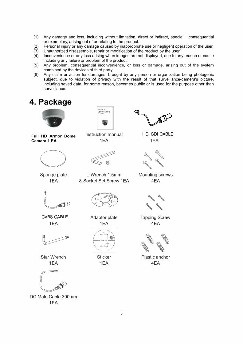
4. Package
Full HD Armor Dome Camera 1 EA
6
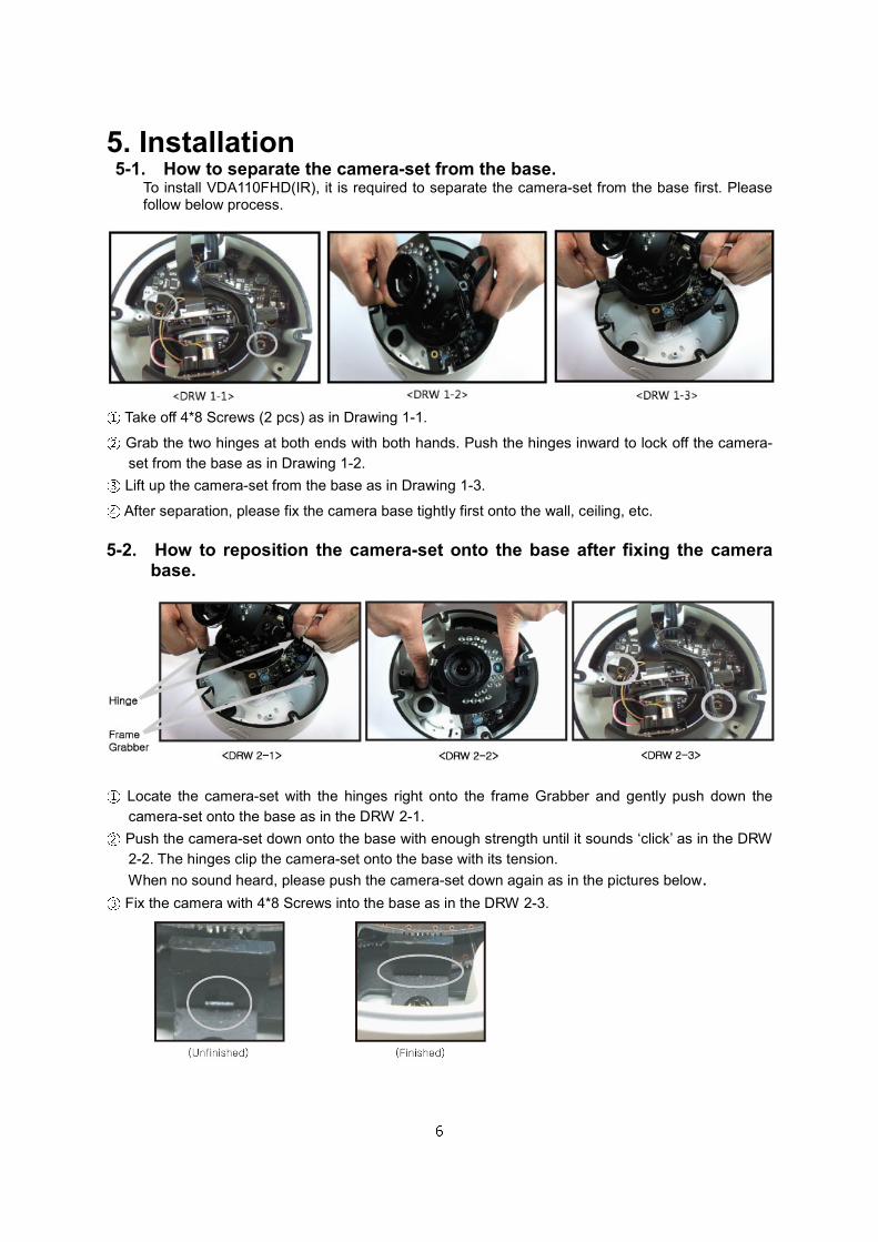
5. Installation 5-1. How to separate the camera-set from the base.
To install VDA110FHD(IR), it is required to separate the camera-set from the base first. Please follow below process.
① Take off 4*8 Screws (2 pcs) as in Drawing 1-1. ② Grab the two hinges at both ends with both hands. Push the hinges inward to lock off the camera-
set from the base as in Drawing 1-2. ③ Lift up the camera-set from the base as in Drawing 1-3. ④ After separation, please fix the camera base tightly first onto the wall, ceiling, etc.
5-2. How to reposition the camera-set onto the base after fixing the camera base.
① Locate the camera-set with the hinges right onto the frame Grabber and gently push down the
camera-set onto the base as in the DRW 2-1. ② Push the camera-set down onto the base with enough strength until it sounds ‘click’ as in the DRW
2-2. The hinges clip the camera-set onto the base with its tension.
When no sound heard, please push the camera-set down again as in the pictures below. ③ Fix the camera with 4*8 Screws into the base as in the DRW 2-3.
7
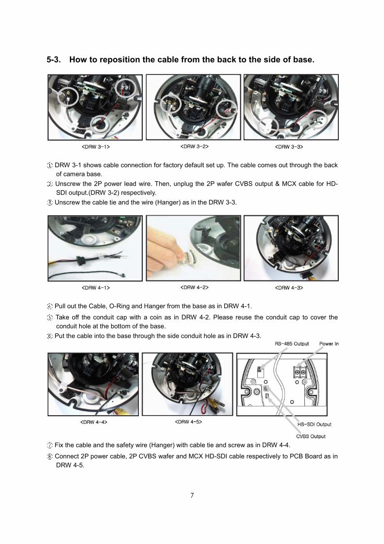
5-3. How to reposition the cable from the back to the side of base.
① DRW 3-1 shows cable connection for factory default set up. The cable comes out through the back
of camera base. ② Unscrew the 2P power lead wire. Then, unplug the 2P wafer CVBS output & MCX cable for HD-
SDI output.(DRW 3-2) respectively. ③ Unscrew the cable tie and the wire (Hanger) as in the DRW 3-3.
④ Pull out the Cable, O-Ring and Hanger from the base as in DRW 4-1. ⑤ Take off the conduit cap with a coin as in DRW 4-2. Please reuse the conduit cap to cover the
conduit hole at the bottom of the base. ⑥ Put the cable into the base through the side conduit hole as in DRW 4-3.
⑦ Fix the cable and the safety wire (Hanger) with cable tie and screw as in DRW 4-4. ⑧ Connect 2P power cable, 2P CVBS wafer and MCX HD-SDI cable respectively to PCB Board as in
DRW 4-5.
8
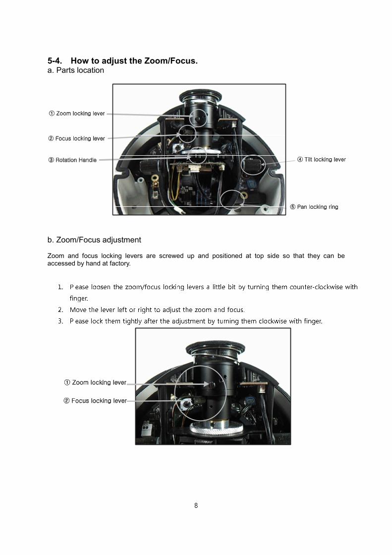
5-4. How to adjust the Zoom/Focus. a. Parts location
b. Zoom/Focus adjustment Zoom and focus locking levers are screwed up and positioned at top side so that they can be accessed by hand at factory.
1. Please loosen the zoom/focus locking levers a little bit by turning them counter-clockwise with finger. 2. Move the lever left or right to adjust the zoom and focus. 3. Please lock them tightly after the adjustment by turning them clockwise with finger.
9
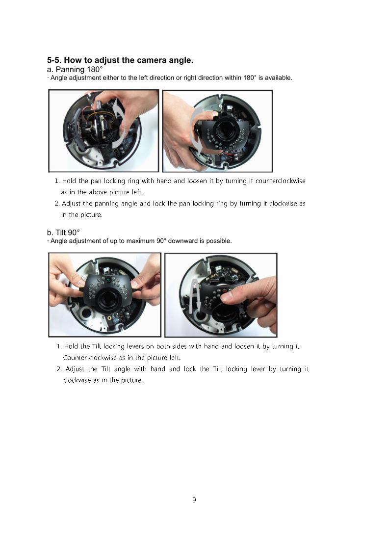
5-5. How to adjust the camera angle. a. Panning 180° · Angle adjustment either to the left direction or right direction within 180° is available.
b. Tilt 90° · Angle adjustment of up to maximum 90° downward is possible.
1. Hold the pan locking ring with hand and loosen it by turning it counterclockwise as in the above picture left. 2. Adjust the panning angle and lock the pan locking ring by turning it clockwise as in the picture.
1. Hold the Tilt locking levers on both sides with hand and loosen it by turning it Counter clockwise as in the picture left. 2. Adjust the Tilt angle with hand and lock the Tilt locking lever by turning it clockwise as in the picture.
10
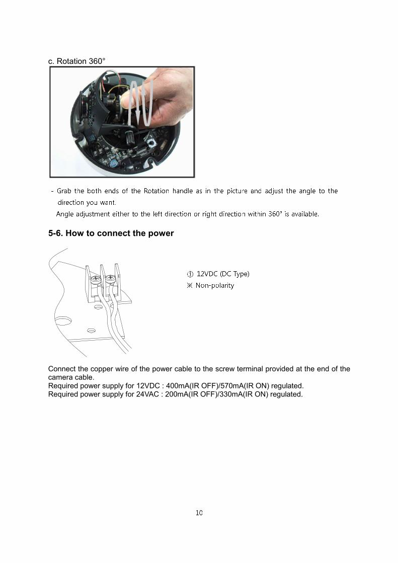
c. Rotation 360°
5-6. How to connect the power
Connect the copper wire of the power cable to the screw terminal provided at the end of the camera cable. Required power supply for 12VDC : 400mA(IR OFF)/570mA(IR ON) regulated. Required power supply for 24VAC : 200mA(IR OFF)/330mA(IR ON) regulated.
- Grab the both ends of the Rotation handle as in the picture and adjust the angle to the direction you want. - Angle adjustment either to the left direction or right direction within 360° is available. ① 12VDC (DC Type) ※ Non-polarity
11
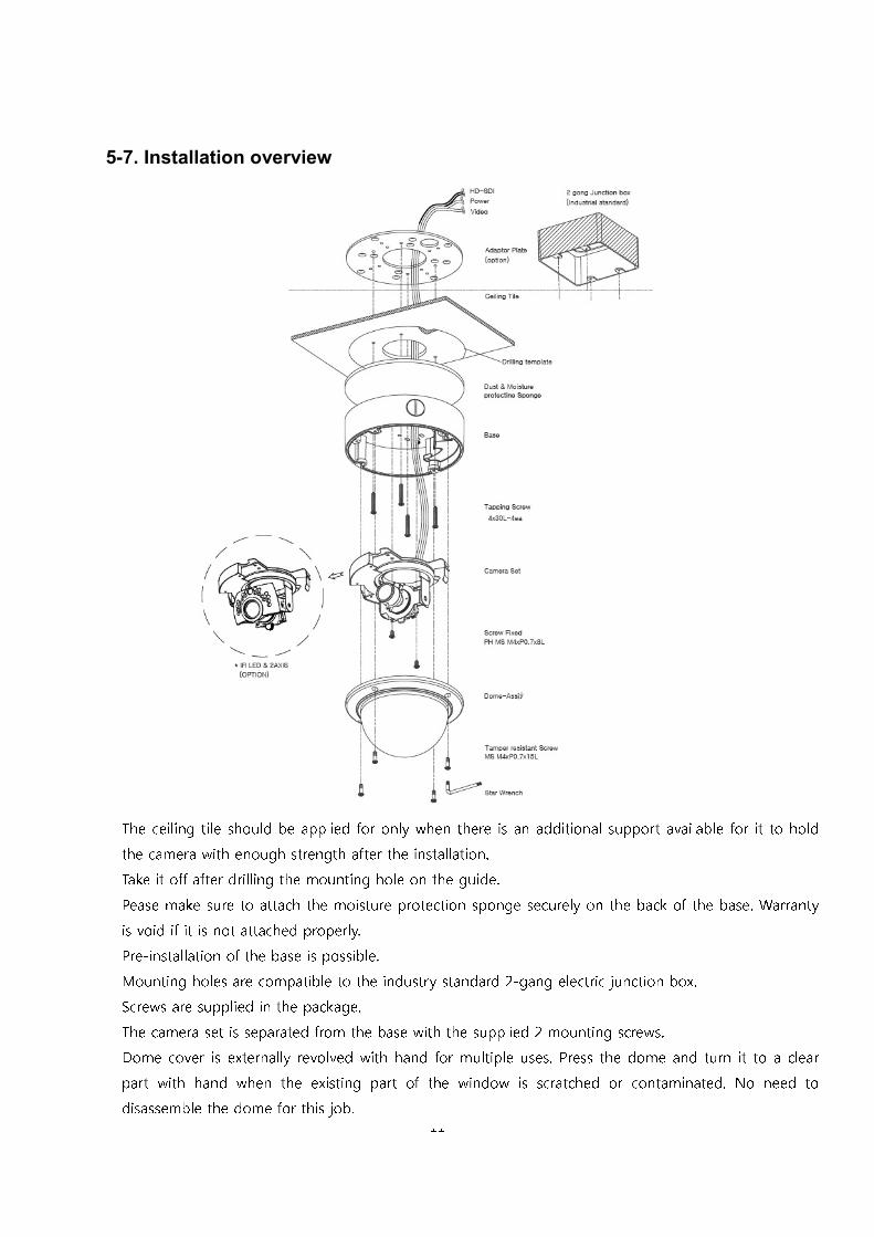
5-7. Installation overview
The ceiling tile should be applied for only when there is an additional support available for it to hold the camera with enough strength after the installation. Take it off after drilling the mounting hole on the guide. Pease make sure to attach the moisture protection sponge securely on the back of the base. Warranty is void if it is not attached properly. Pre-installation of the base is possible. Mounting holes are compatible to the industry standard 2-gang electric junction box. Screws are supplied in the package. The camera set is separated from the base with the supplied 2 mounting screws. Dome cover is externally revolved with hand for multiple uses. Press the dome and turn it to a clear part with hand when the existing part of the window is scratched or contaminated. No need to disassemble the dome for this job.
12
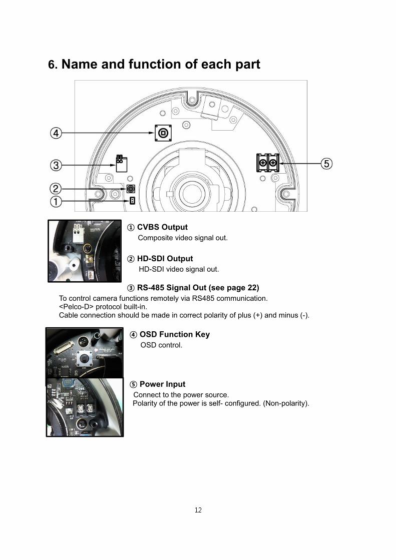
6. Name and function of each part
① CVBS Output Composite video signal out.
② HD-SDI Output HD-SDI video signal out.
③ RS-485 Signal Out (see page 22) To control camera functions remotely via RS485 communication. <Pelco-D> protocol built-in. Cable connection should be made in correct polarity of plus (+) and minus (-).
④ OSD Function Key OSD control.
⑤ Power Input Connect to the power source. Polarity of the power is self- configured. (Non-polarity).
13
7. Function and operation
7-1. On Screen Display Menu
MAIN MENU
VIDEO OUT VIDEO OUTSIZE FRAME RATE CVBS OUT MODE SAVE/
RETURN
AUTO MENU NORMAL 50HZ INDOOR 60HZ INDOOR OUTDOOR RETURN
DAY/NIGHT AUTO/COLOR/IR D TO N LEVEL
N TO D LEVEL
D TO N TIME
N TO D TIME
D/N RESET RETURN
AWB (ATW)/PUSH/HOLD
TRACK/USER/8000K/
6000K/4200K/3200K
RED BLUE AWB RESET RETURN
AE IRIS
ATR-EX(WDR)
DSS
DC IRIS
BLC/FLC
BRIGHTNESS
LSC
FLICKERLESS
AGC
AE RESET
RETURN
PRIVACY AREA NUMBER
MASK POSITION
MASK DEFINE
PRIVACY RESET
MASK PATTERN MASK SIZE RETURN
EFFECT COLOR ADJUST
2DNR
SHARPNESS
3DNR
CONTRAST
EFFECT RESET
REVERSAL
RETURN
SYSTEM CAMERA ID
FIRMWARE
ID DISPLAY
485 TERM
CAMERA NAME
BAUD RATE
NAME DISPLAY
SYSTEM RESET
RETURN
INITIALIZE FACTORY INIT RETURN
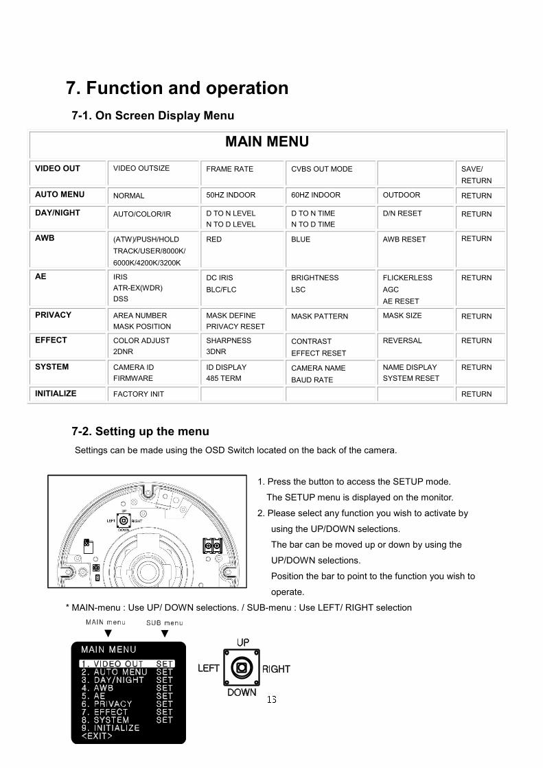
7-2. Setting up the menu
Settings can be made using the OSD Switch located on the back of the camera.
1. Press the button to access the SETUP mode.
The SETUP menu is displayed on the monitor.
2. Please select any function you wish to activate by
using the UP/DOWN selections.
The bar can be moved up or down by using the
UP/DOWN selections.
Position the bar to point to the function you wish to
operate.
* MAIN-menu : Use UP/ DOWN selections. / SUB-menu : Use LEFT/ RIGHT selection
14
3. Change the status of the selected feature using the LEFT/RIGHT selections.
When the LEFT or RIGHT selection is selected, available values and modes are displayed in order.
Please keep the selection until you get to the mode you wish to operate.
4. When completed, move the bar indicator to ‘EXIT’ and press the button to finish the setting.
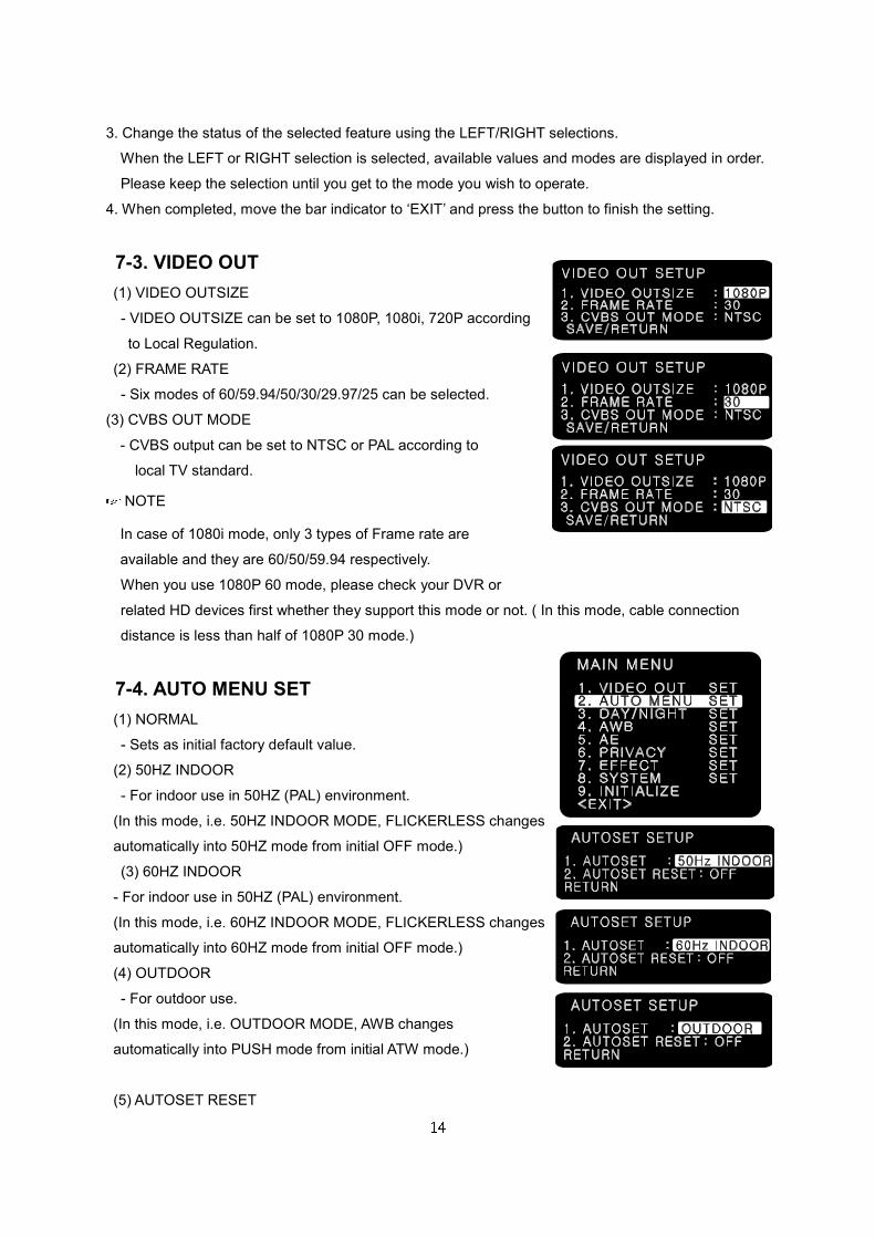
7-3. VIDEO OUT
(1) VIDEO OUTSIZE
- VIDEO OUTSIZE can be set to 1080P, 1080i, 720P according
to Local Regulation.
(2) FRAME RATE
- Six modes of 60/59.94/50/30/29.97/25 can be selected.
(3) CVBS OUT MODE
- CVBS output can be set to NTSC or PAL according to
local TV standard. NOTE
In case of 1080i mode, only 3 types of Frame rate are
available and they are 60/50/59.94 respectively.
When you use 1080P 60 mode, please check your DVR or
related HD devices first whether they support this mode or not. ( In this mode, cable connection
distance is less than half of 1080P 30 mode.)
7-4. AUTO MENU SET
(1) NORMAL
- Sets as initial factory default value.
(2) 50HZ INDOOR
- For indoor use in 50HZ (PAL) environment.
(In this mode, i.e. 50HZ INDOOR MODE, FLICKERLESS changes
automatically into 50HZ mode from initial OFF mode.)
(3) 60HZ INDOOR
- For indoor use in 50HZ (PAL) environment.
(In this mode, i.e. 60HZ INDOOR MODE, FLICKERLESS changes
automatically into 60HZ mode from initial OFF mode.)
(4) OUTDOOR
- For outdoor use.
(In this mode, i.e. OUTDOOR MODE, AWB changes
automatically into PUSH mode from initial ATW mode.)
(5) AUTOSET RESET
15
- When set as ON and press SET KEY, it turns into
AUTOSET NORMAL MODE automatically, which means
initial factory reset.
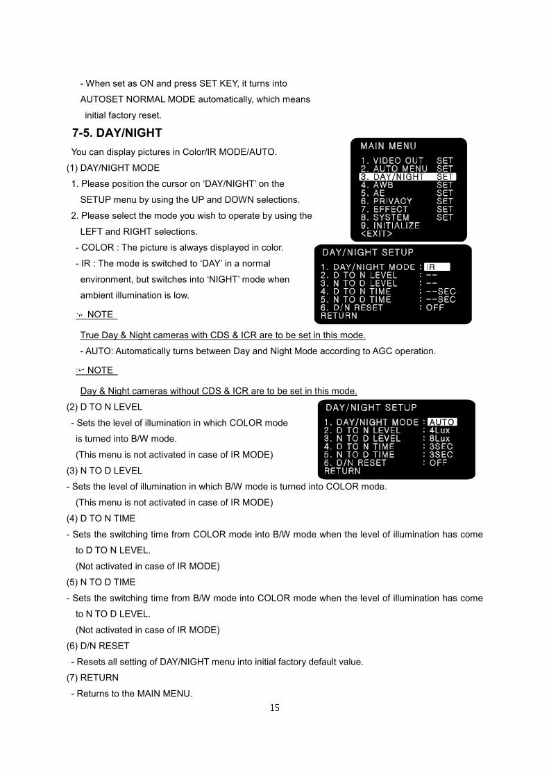
7-5. DAY/NIGHT
You can display pictures in Color/IR MODE/AUTO.
(1) DAY/NIGHT MODE
1. Please position the cursor on ‘DAY/NIGHT’ on the
SETUP menu by using the UP and DOWN selections.
2. Please select the mode you wish to operate by using the
LEFT and RIGHT selections.
- COLOR : The picture is always displayed in color.
- IR : The mode is switched to ‘DAY’ in a normal
environment, but switches into ‘NIGHT’ mode when
ambient illumination is low. NOTE
True Day & Night cameras with CDS & ICR are to be set in this mode.
- AUTO: Automatically turns between Day and Night Mode according to AGC operation. NOTE
Day & Night cameras without CDS & ICR are to be set in this mode.
(2) D TO N LEVEL
- Sets the level of illumination in which COLOR mode
is turned into B/W mode.
(This menu is not activated in case of IR MODE)
(3) N TO D LEVEL
- Sets the level of illumination in which B/W mode is turned into COLOR mode.
(This menu is not activated in case of IR MODE)
(4) D TO N TIME
- Sets the switching time from COLOR mode into B/W mode when the level of illumination has come
to D TO N LEVEL.
(Not activated in case of IR MODE)
(5) N TO D TIME
- Sets the switching time from B/W mode into COLOR mode when the level of illumination has come
to N TO D LEVEL.
(Not activated in case of IR MODE)
(6) D/N RESET
- Resets all setting of DAY/NIGHT menu into initial factory default value.
(7) RETURN
- Returns to the MAIN MENU.
16
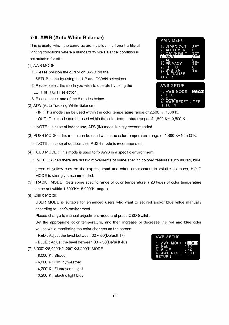
7-6. AWB (Auto White Balance)
This is useful when the cameras are installed in different artificial
lighting conditions where a standard ‘White Balance’ condition is
not suitable for all.
(1) AWB MODE
1. Please position the cursor on ‘AWB’ on the
SETUP menu by using the UP and DOWN selections.
2. Please select the mode you wish to operate by using the
LEFT or RIGHT selection.
3. Please select one of the 8 modes below.
(2) ATW (Auto Tracking White Balance)
- IN : This mode can be used within the color temperature range of 2,500˚K~7000˚K.
- OUT : This mode can be used within the color temperature range of 1,800˚K~10,500˚K. NOTE : In case of indoor use, ATW(IN) mode is higly recommended.
(3) PUSH MODE : This mode can be used within the color temperature range of 1,800˚K~10,500˚K. NOTE : In case of outdoor use, PUSH mode is recommended.
(4) HOLD MODE : This mode is used to fix AWB in a specific environment. NOTE : When there are drastic movements of some specific colored features such as red, blue,
green or yellow cars on the express road and when environment is volatile so much, HOLD
MODE is strongly rcecommended.
(5) TRACK MODE : Sets some specific range of color temperature. ( 23 types of color temperature
can be set within 1,500˚K~15,000˚K range.)
(6) USER MODE
USER MODE is suitable for enhanced users who want to set red and/or blue value manually
according to user’s environment.
Please change to manual adjustment mode and press OSD Switch.
Set the appropriate color temperature, and then increase or decrease the red and blue color
values while monitoring the color changes on the screen.
- RED : Adjust the level between 00 ~ 50(Default 17)
- BLUE : Adjust the level between 00 ~ 50(Default 40)
(7) 8,000˚K/6,000˚K/4,200˚K/3,200˚K MODE
- 8,000˚K : Shade
- 6,000˚K : Cloudy weather
- 4,200˚K : Fluorescent light
- 3,200˚K : Electric light blub
17
(8) AWB RESET
- Resets all setting of AWB menu into initial factory reset value.
(9) RETURN
- Returns to the MAIN MENU.
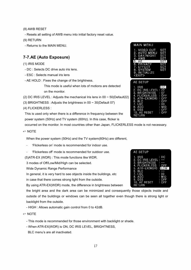
7-7.AE (Auto Exposure)
(1) IRIS MODE
- DC : Selects DC drive auto iris lens.
- ESC : Selects manual iris lens
- AE HOLD : Fixes the change of the brightness.
This mode is useful when lots of motions are detected
on the monitor.
(2) DC IRIS LEVEL : Adjusts the mechanical Iris lens in 00 ~ 50(Default22)
(3) BRIGHTNESS : Adjusts the brightness in 00 ~ 30(Default 07)
(4) FLICKERLESS :
This is used only when there is a difference in frequency between the
power system (50Hz) and TV system (60Hz). In this case, flicker is
occurred on the monitor. In most countries other than Japan, FLICKERLESS mode is not necessary. NOTE
When the power system (50Hz) and the TV system(60Hz) are different, - ‘Flickerless on’ mode is recommended for indoor use. - ‘Flickerless off’ mode is recommended for outdoor use.
(5)ATR-EX (WDR) : This mode functions like WDR.
3 modes of Off/Low/Mid/High can be selected.
Wide Dynamic Range Performance
In general, it is very hard to see objects inside the buildings, etc
in case that there comes strong light from the outside.
By using ATR-EX(WDR) mode, the difference in brightness between
the bright area and the dark area can be minimized and consequently those objects inside and
outside of the buildings or windows can be seen all together even though there is strong light or
backlight from the outside.
- HIGH : Allows automatic gain control from 0 to 42dB. NOTE
- This mode is recommended for those environment with backlight or shade.
- When ATR-EX(WDR) is ON, DC IRIS LEVEL, BRIGHTNESS,
BLC menu’s are all inactivated.
18
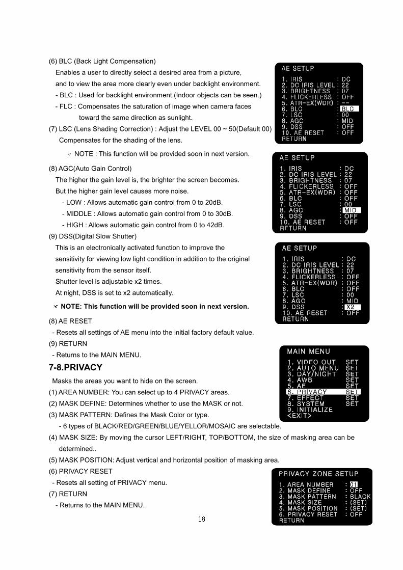
(6) BLC (Back Light Compensation)
Enables a user to directly select a desired area from a picture,
and to view the area more clearly even under backlight environment.
- BLC : Used for backlight environment.(Indoor objects can be seen.)
- FLC : Compensates the saturation of image when camera faces
toward the same direction as sunlight.
(7) LSC (Lens Shading Correction) : Adjust the LEVEL 00 ~ 50(Default 00)
Compensates for the shading of the lens.
NOTE : This function will be provided soon in next version.
(8) AGC(Auto Gain Control)
The higher the gain level is, the brighter the screen becomes.
But the higher gain level causes more noise.
- LOW : Allows automatic gain control from 0 to 20dB.
- MIDDLE : Allows automatic gain control from 0 to 30dB.
- HIGH : Allows automatic gain control from 0 to 42dB.
(9) DSS(Digital Slow Shutter)
This is an electronically activated function to improve the
sensitivity for viewing low light condition in addition to the original
sensitivity from the sensor itself.
Shutter level is adjustable x2 times.
At night, DSS is set to x2 automatically. NOTE: This function will be provided soon in next version. (8) AE RESET
- Resets all settings of AE menu into the initial factory default value.
(9) RETURN
- Returns to the MAIN MENU.
7-8.PRIVACY
Masks the areas you want to hide on the screen.
(1) AREA NUMBER: You can select up to 4 PRIVACY areas.
(2) MASK DEFINE: Determines whether to use the MASK or not.
(3) MASK PATTERN: Defines the Mask Color or type.
- 6 types of BLACK/RED/GREEN/BLUE/YELLOR/MOSAIC are selectable.
(4) MASK SIZE: By moving the cursor LEFT/RIGHT, TOP/BOTTOM, the size of masking area can be
determined..
(5) MASK POSITION: Adjust vertical and horizontal position of masking area.
(6) PRIVACY RESET
- Resets all setting of PRIVACY menu.
(7) RETURN
- Returns to the MAIN MENU.
19
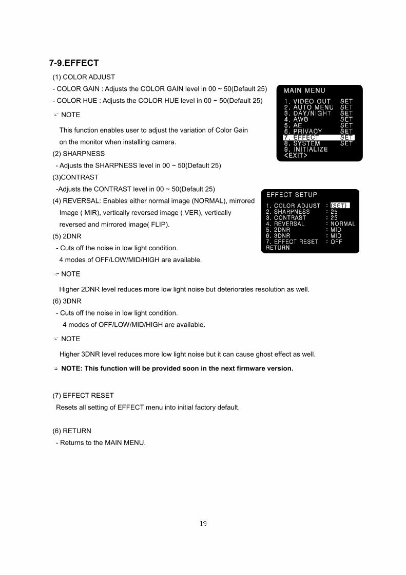
7-9.EFFECT
(1) COLOR ADJUST
- COLOR GAIN : Adjusts the COLOR GAIN level in 00 ~ 50(Default 25)
- COLOR HUE : Adjusts the COLOR HUE level in 00 ~ 50(Default 25) NOTE
This function enables user to adjust the variation of Color Gain
on the monitor when installing camera.
(2) SHARPNESS
- Adjusts the SHARPNESS level in 00 ~ 50(Default 25)
(3)CONTRAST
-Adjusts the CONTRAST level in 00 ~ 50(Default 25)
(4) REVERSAL: Enables either normal image (NORMAL), mirrored
Image ( MIR), vertically reversed image ( VER), vertically
reversed and mirrored image( FLIP).
(5) 2DNR
- Cuts off the noise in low light condition.
4 modes of OFF/LOW/MID/HIGH are available. NOTE
Higher 2DNR level reduces more low light noise but deteriorates resolution as well.
(6) 3DNR
- Cuts off the noise in low light condition.
4 modes of OFF/LOW/MID/HIGH are available. NOTE
Higher 3DNR level reduces more low light noise but it can cause ghost effect as well. NOTE: This function will be provided soon in the next firmware version.
(7) EFFECT RESET
Resets all setting of EFFECT menu into initial factory default.
(6) RETURN
- Returns to the MAIN MENU.
20
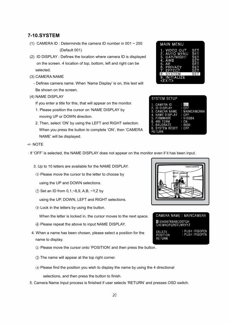
7-10.SYSTEM
(1) CAMERA ID : Determinds the camera ID number in 001 ~ 255
(Default 001)
(2) ID DISPLAY : Defines the location where camera ID is displayed
on the screen. 4 location of top, bottom, left and right can be
selected.
(3) CAMERA NAME
- Defines camera name. When ‘Name Display’ is on, this text will
Be shown on the screen.
(4) NAME DISPLAY
If you enter a title for this, that will appear on the monitor.
1. Please position the cursor on ‘NAME DISPLAY by
moving UP or DOWN direction.
2. Then, select ‘ON’ by using the LEFT and RIGHT selection.
When you press the button to complete ‘ON’, then ‘CAMERA
NAME’ will be displayed. NOTE
· If ‘OFF’ is selected, the NAME DISPLAY does not appear on the monitor even if it has been input.
3. Up to 10 letters are available for the NAME DISPLAY. ① Please move the cursor to the letter to choose by
using the UP and DOWN selections. ② Set an ID from 0,1,~8,9, A,B, ~Y,Z by
using the UP, DOWN, LEFT and RIGHT selections. ③ Lock in the letters by using the button.
When the letter is locked in, the cursor moves to the next space. ④ Please repeat the above to input NAME DISPLAY.
4. When a name has been chosen, please select a position for the
name to display.
① Please move the cursor onto ’POSITION’ and then press the button. ② The name will appear at the top right corner. ③ Please find the position you wish to display the name by using the 4 directional
selections, and then press the button to finish.
5. Camera Name Input process is finished if user selects ‘RETURN’ and presses OSD switch.
21
(5) FIRMWARE:
- Shows firmware version of this camera unit.
(6) 485 TERM
- RS485 Function ON/OFF
(7) BAUD RATE
- Selects baud rate for RS485 communication among 2400/ 4800/ 9600. (Default:9600)
(8) SYSTEM RESET
- Resets all setting of SYSTEM menu.
CAMERA ID, 485 TERM settings are not initialized.
(9) RETURN
- Returns to the MAIN MENU.
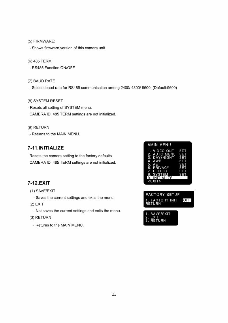
7-11.INITIALIZE
Resets the camera setting to the factory defaults.
CAMERA ID, 485 TERM settings are not initialized.
7-12.EXIT
(1) SAVE/EXIT
- Saves the current settings and exits the menu.
(2) EXIT
- Not saves the current settings and exits the menu.
(3) RETURN
- Returns to the MAIN MENU.
22
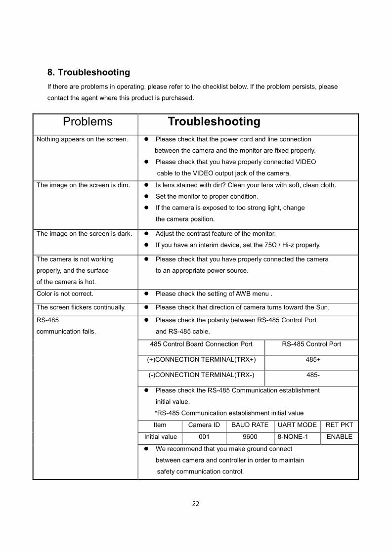
8. Troubleshooting
If there are problems in operating, please refer to the checklist below. If the problem persists, please
contact the agent where this product is purchased.
Problems Troubleshooting
Nothing appears on the screen. Please check that the power cord and line connection
between the camera and the monitor are fixed properly.
Please check that you have properly connected VIDEO
cable to the VIDEO output jack of the camera.
The image on the screen is dim. Is lens stained with dirt? Clean your lens with soft, clean cloth.
Set the monitor to proper condition.
If the camera is exposed to too strong light, change
the camera position.
The image on the screen is dark. Adjust the contrast feature of the monitor.
If you have an interim device, set the 75Ω / Hi-z properly.
The camera is not working
properly, and the surface
of the camera is hot.
Please check that you have properly connected the camera
to an appropriate power source.
Color is not correct. Please check the setting of AWB menu .
The screen flickers continually. Please check that direction of camera turns toward the Sun.
RS-485
communication fails.
Please check the polarity between RS-485 Control Port
and RS-485 cable.
485 Control Board Connection Port RS-485 Control Port
(+)CONNECTION TERMINAL(TRX+) 485+
(-)CONNECTION TERMINAL(TRX-) 485-
Please check the RS-485 Communication establishment
initial value.
*RS-485 Communication establishment initial value
Item Camera ID BAUD RATE UART MODE RET PKT
Initial value 001 9600 8-NONE-1 ENABLE
We recommend that you make ground connect
between camera and controller in order to maintain
safety communication control.
23
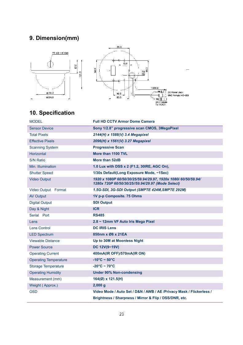
9. Dimension(mm)
10. Specification
MODEL Full HD CCTV Armor Dome Camera
Sensor Device Sony 1/2.8” progressive scan CMOS, 3MegaPixel
Total Pixels 2144(H) x 1588(V) 3.4 Megapixel
Effective Pixels 2096(H) x 1561(V) 3.27 Megapixel
Scanning System Progressive Scan
Horizontal More than 1100 TVL
S/N Ratio More than 52dB
Min. Illumination 1.0 Lux with DSS x 2 (F1.2, 30IRE, AGC On),
Shutter Speed 1/30s Default(Long Exposure Mode, ~1Sec)
Video Output 1920 x 1080P 60/50/30/25/59.94/29.97, 1920x 1080i 60/50/59.94/ 1280x 720P 60/50/30/25//59.94/29.97 (Mode Select)
Video Output Format 1.5G-SDI, 3G-SDI Output (SMPTE 424M,SMPTE 292M)
AV Output 1V p-p Composite. 75 Ohms
Digital Output SDI Output
Day & Night ICR
Serial Port RS485
Lens 2.8 ~ 12mm VF Auto Iris Mega Pixel
Lens Control DC IRIS Lens
LED Spectrum 850nm x Ø8 x 21EA
Viewable Distance Up to 30M at Moonless Night
Power Source DC 12V(9~19V)
Operating Current 400mA(IR OFF)/570mA(IR ON)
Operating Temperature -10°C ~ 50°C
Storage Temperature -20°C ~ 70°C
Operating Humidity Under 90% Non-condensing
Measurement (mm) 164(Ø) x 121.5(H)
Weight ( Approx.) 2,000 g
OSD Video Mode / Auto Set / D&N / AWB / AE /Privacy Mask / Flickerless /
Brightness / Sharpness / Mirror & Flip / DSS/DNR, etc.