Embed Size (px)
Citation preview
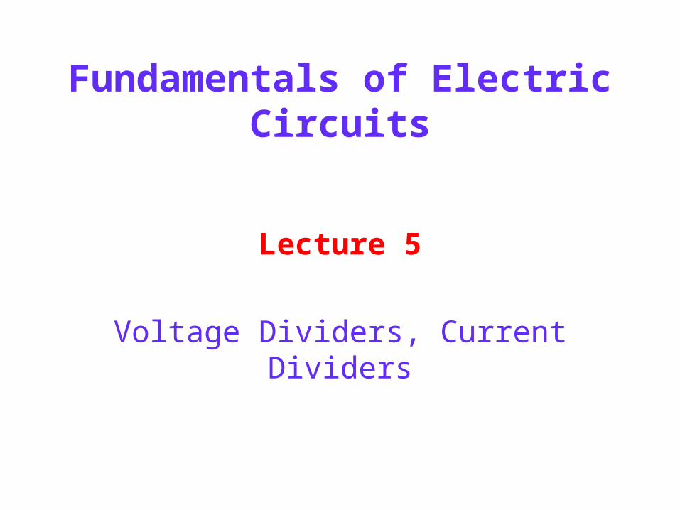
Fundamentals of Electric Circuits
Lecture 5
Voltage Dividers, Current Dividers
2
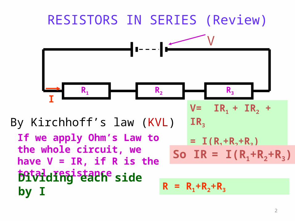
RESISTORS IN SERIES (Review)
IR1 R2 R3
V
By Kirchhoff’s law (KVL)V= IR1 + IR2 + IR3
= I(R1+R2+R3)If we apply Ohm’s Law to the whole circuit, we have V = IR, if R is the total resistance
So IR = I(R1+R2+R3)
Dividing each side by I R = R1+R2+R3
3
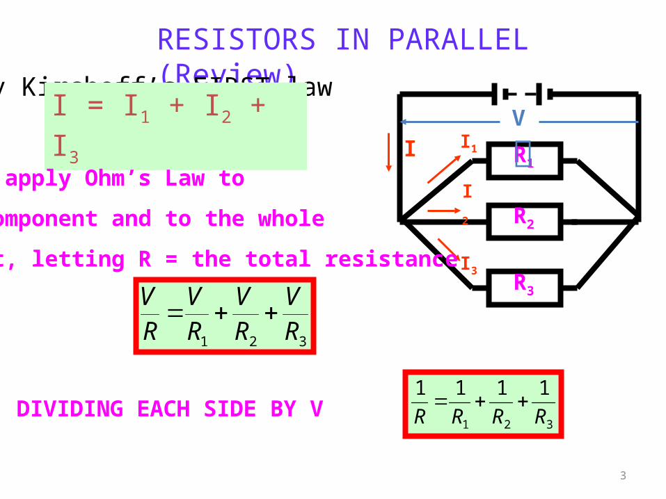
RESISTORS IN PARALLEL (Review)
R1
R2
R3
V
I I1
I2
I3
By Kirchoff’s FIRST law
I = I1 + I2 + I3
We now apply Ohm’s Law to
each component and to the whole
circuit, letting R = the total resistance
321 RV
RV
RV
RV
DIVIDING EACH SIDE BY V321
1111
RRRR
4
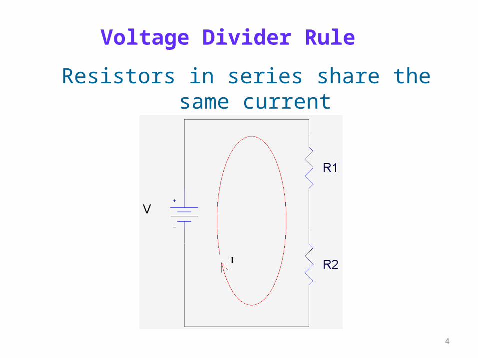
Voltage Divider Rule
Resistors in series share the same current
5
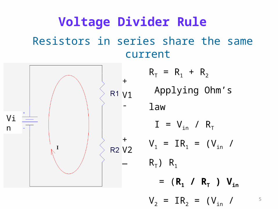
Resistors in series share the same current
RT = R1 + R2
Applying Ohm’s law
I = Vin / RT
V1 = IR1 = (Vin / RT) R1
= (R1 / RT ) Vin
V2 = IR2 = (Vin / RT) R2
= (R2 / RT ) Vin
+
V1-
+V2_
Vin
Voltage Divider Rule
6
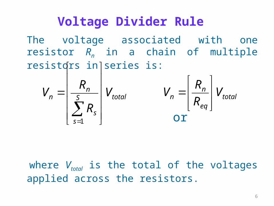
The voltage associated with one resistor Rn in a chain of multiple resistors in series is:
or
where Vtotal is the total of the voltages applied across the resistors.
totaleq
nn V
R
RV
totalS
ss
nn V
R
RV
1
Voltage Divider Rule
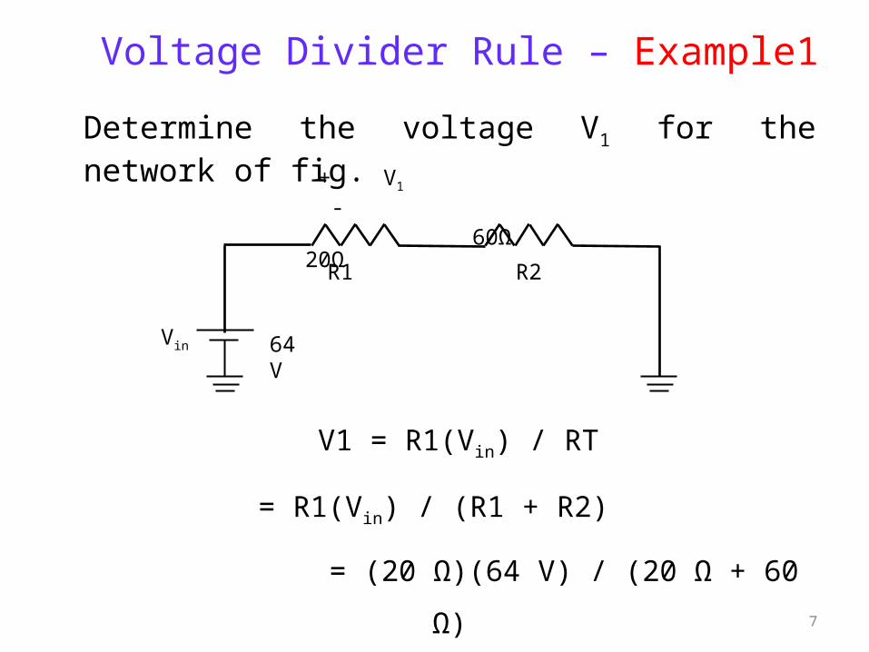
7
Determine the voltage V1 for the network of fig.
V1 = R1(Vin) / RT
= R1(Vin) / (R1 + R2)
= (20 Ω)(64 V) / (20 Ω + 60 Ω)
= 1280 / 80 = 16 V
Voltage Divider Rule – Example1
+ V1 - 20Ω
60Ω
R2R1
Vin 64 V
Voltage Divider Rule –Example 2
Using the voltage divider rule, determine the voltage V1 and V3 for the series circuit
+
Vin
-
R1
R2
R3
45V
2 kΩ
5 kΩ
8 kΩ
+V1
-
+V3
-
+
V’
-
V
V
kkk
Vk
R
VRV
VV
k
Vk
kkk
Vk
R
VRV
T
in
T
in
2415
360
1015
)45)(108(
852
)45)(8(
615
90
1015
)45)(102(
15
)45)(2(
852
)45)(2(
3
33
3
3
3
11
9
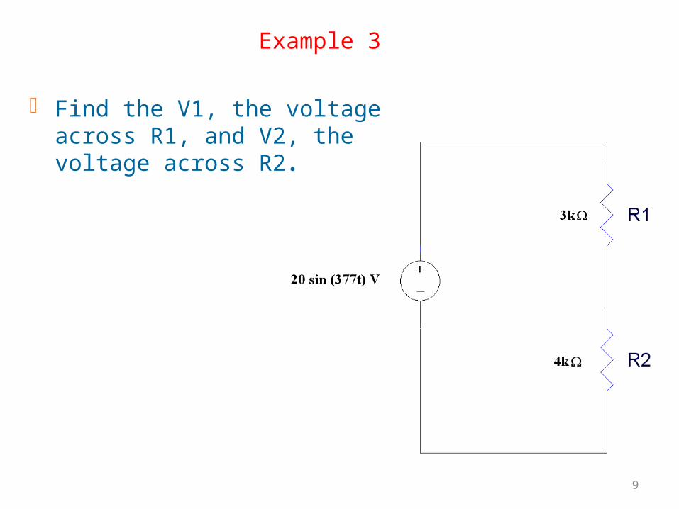
Example 3
Find the V1, the voltage across R1, and V2, the voltage across R2.
10
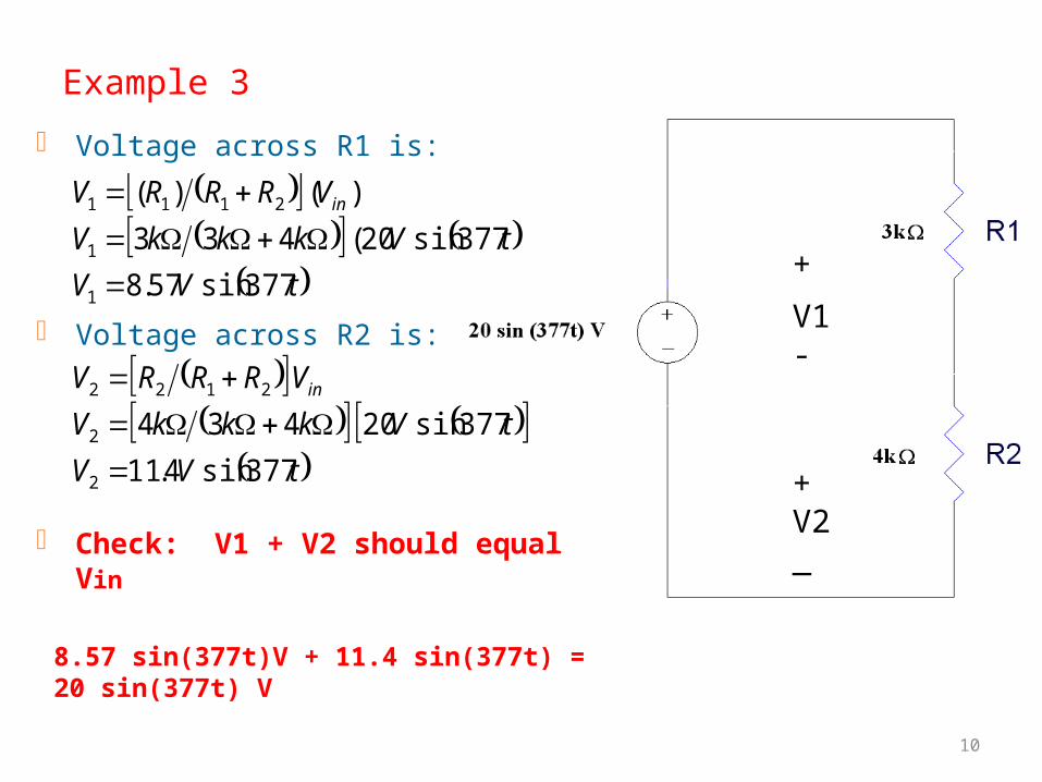
Example 3
Voltage across R1 is:
Voltage across R2 is:
Check: V1 + V2 should equal Vin
+
V1-
+V2_
tVV
tVkkkV
VRRRV
tVV
tVkkkV
VRRRV
in
in
377sin4.11
377sin20 434
377sin57.8
377sin20( 433
)( )(
2
2
2122
1
1
2111
8.57 sin(377t)V + 11.4 sin(377t) = 20 sin(377t) V
11
+V1 -
+V2 -
+V3 -
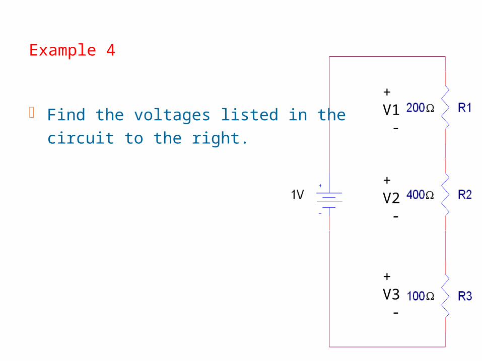
Example 4
Find the voltages listed in the circuit to the right.
12
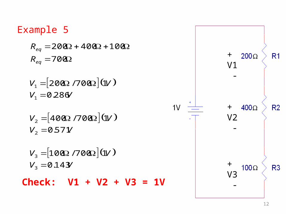
Example 5
Check: V1 + V2 + V3 = 1V
VV
VV
VV
VV
VV
VV
R
R
eq
eq
143.0
1 700/100
571.0
1 700/400
286.0
1 700/200
700
100400200
3
3
2
2
1
1
+V1 -
+V2 -
+V3 -
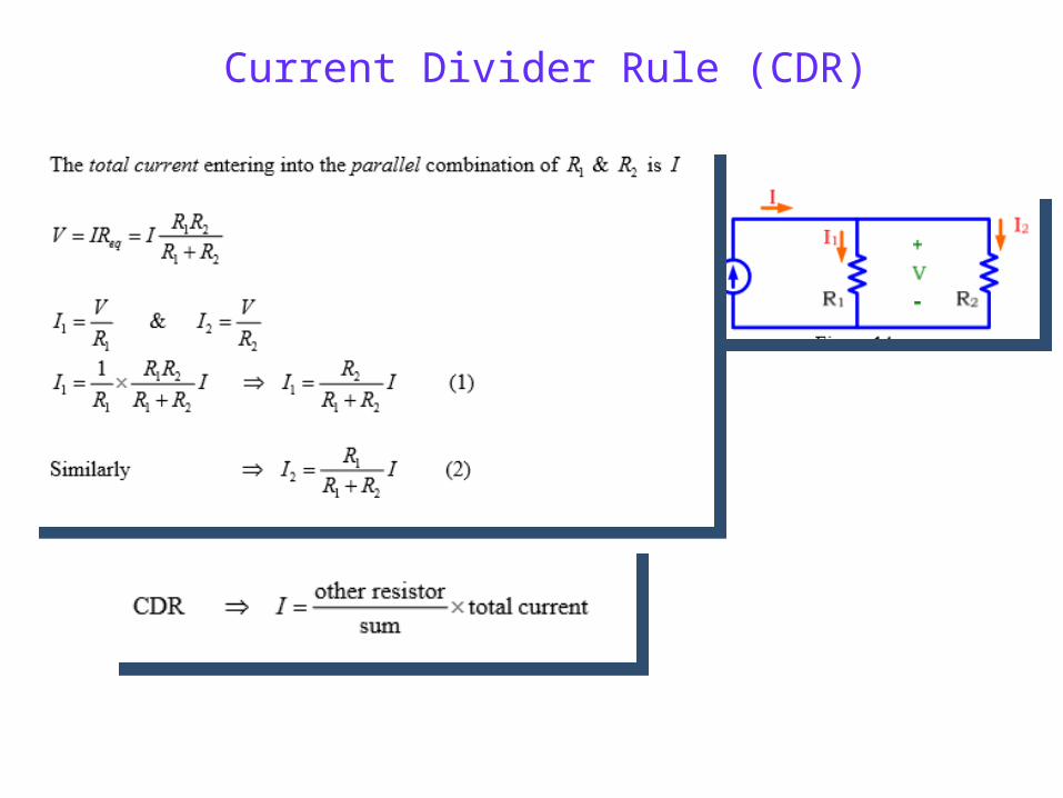
Current Divider Rule (CDR)
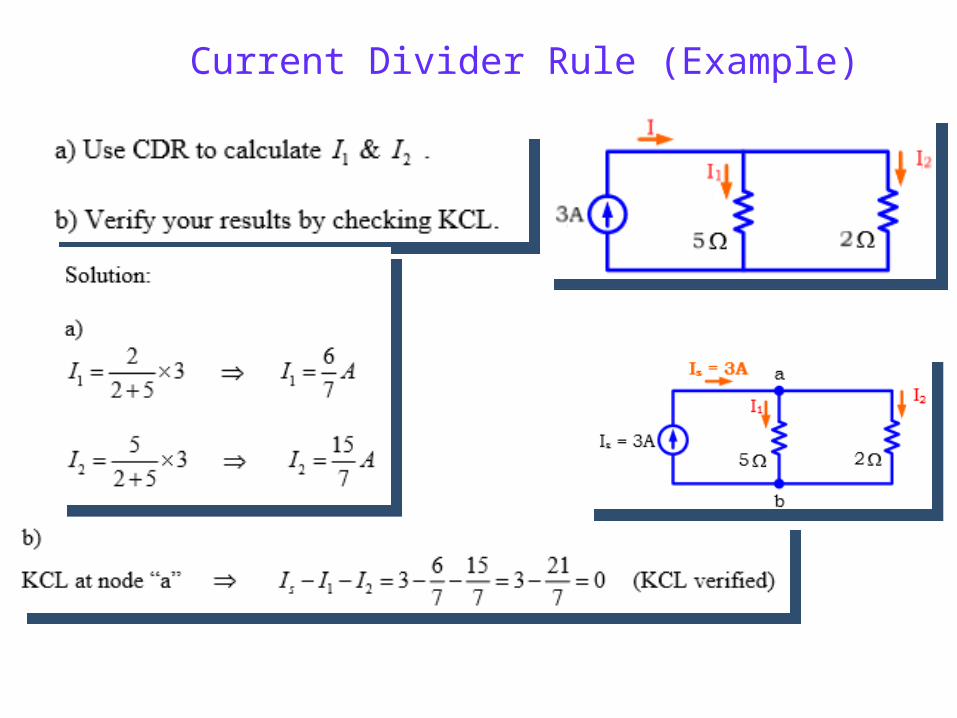
Current Divider Rule (Example)
15
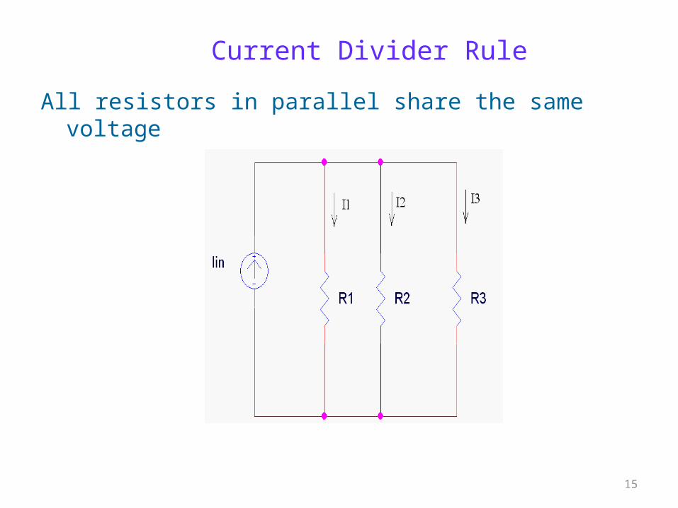
Current Divider Rule
All resistors in parallel share the same voltage
16
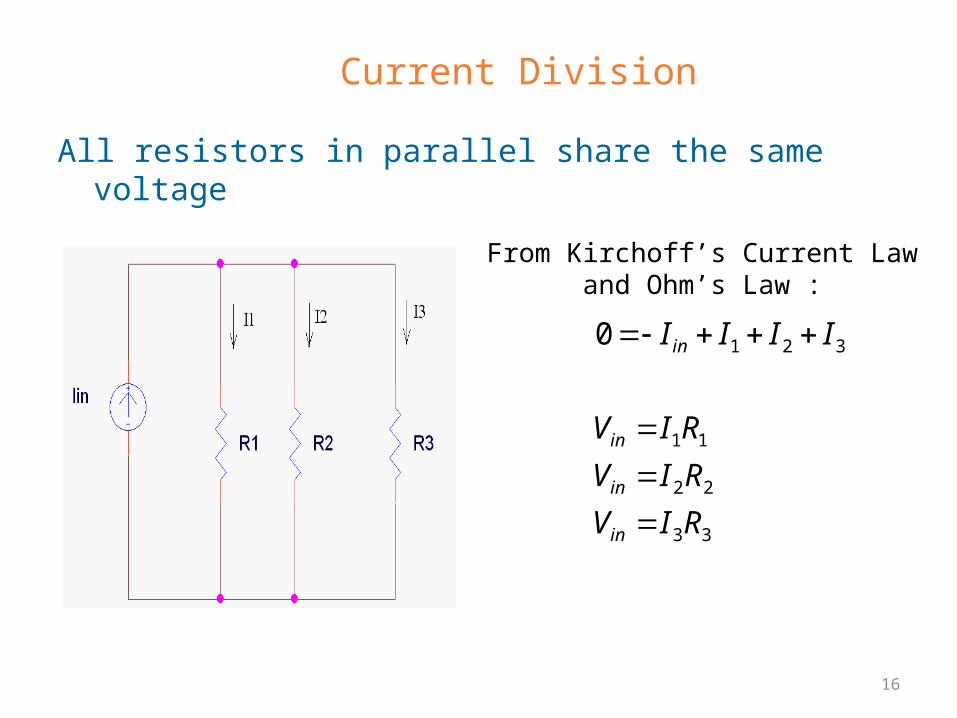
All resistors in parallel share the same voltage
From Kirchoff’s Current Law and Ohm’s Law :
33
22
11
3210
RIV
RIV
RIV
IIII
in
in
in
in
Current Division
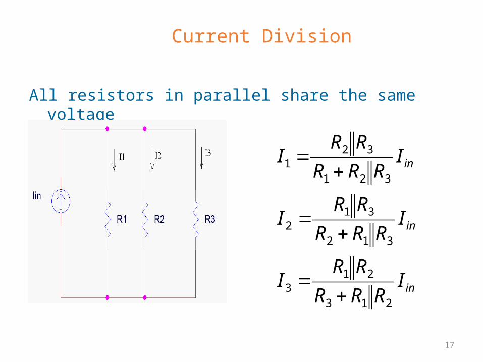
17
All resistors in parallel share the same voltage
in
in
in
IRRR
RRI
IRRR
RRI
IRRR
RRI
213
213
312
312
321
321
Current Division
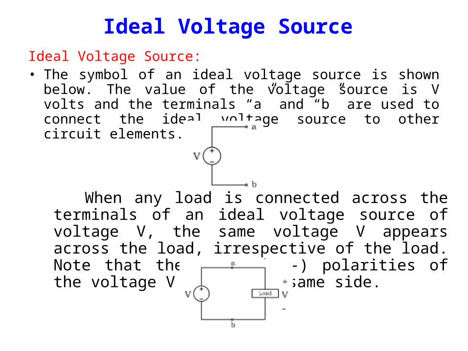
Ideal Voltage Source Ideal Voltage Source: • The symbol of an ideal voltage source is shown below. The
value of the voltage source is V volts and the terminals “a” and “b” are used to connect the ideal voltage source to other circuit elements.
When any load is connected across the terminals of an ideal voltage source of voltage V, the same voltage V appears across the load, irrespective of the load. Note that the (+) and (-) polarities of the voltage V are on the same side.
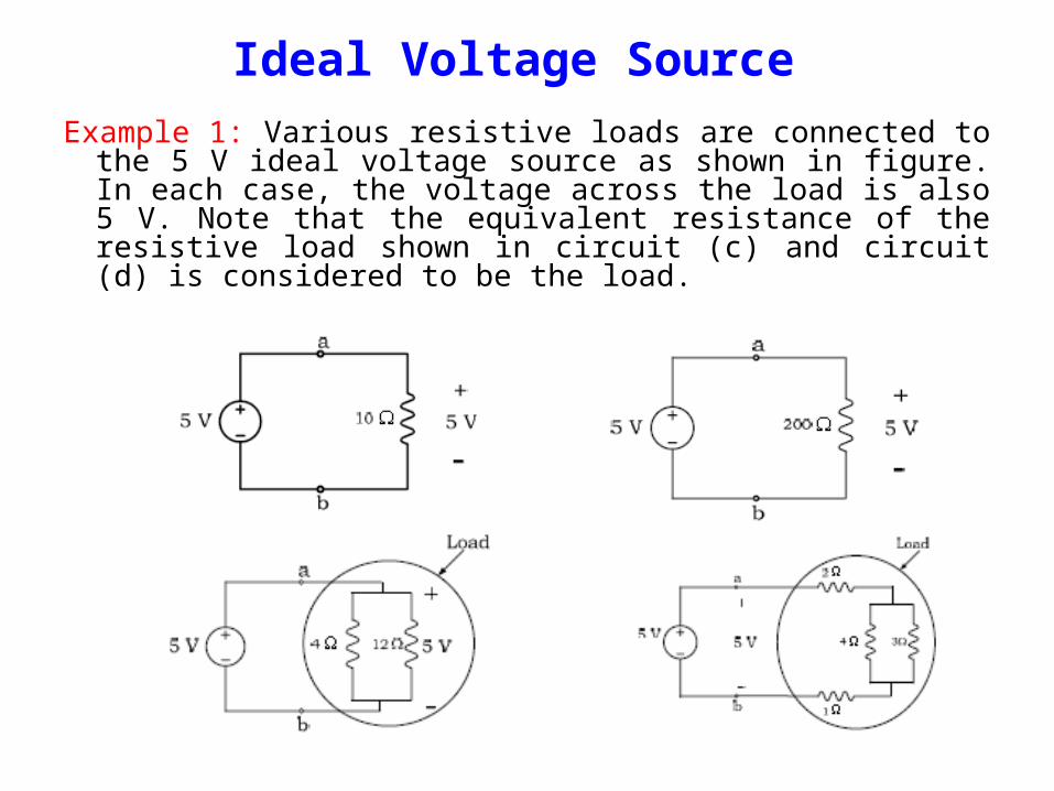
Example 1: Various resistive loads are connected to the 5 V ideal voltage source as shown in figure. In each case, the voltage across the load is also 5 V. Note that the equivalent resistance of the resistive load shown in circuit (c) and circuit (d) is considered to be the load.
Ideal Voltage Source
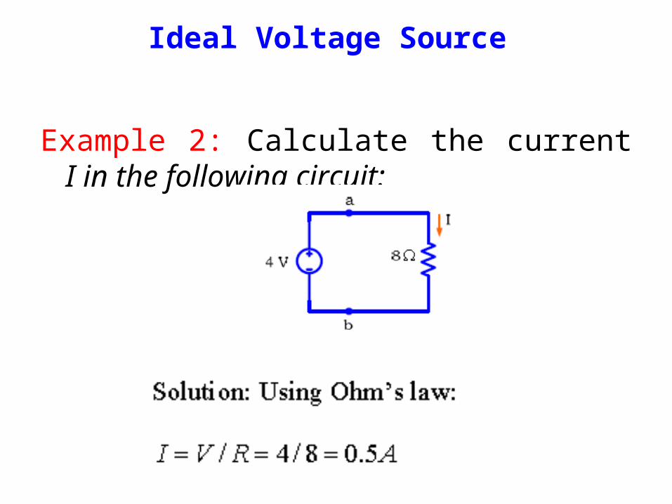
Example 2: Calculate the current I in the following circuit:
Ideal Voltage Source
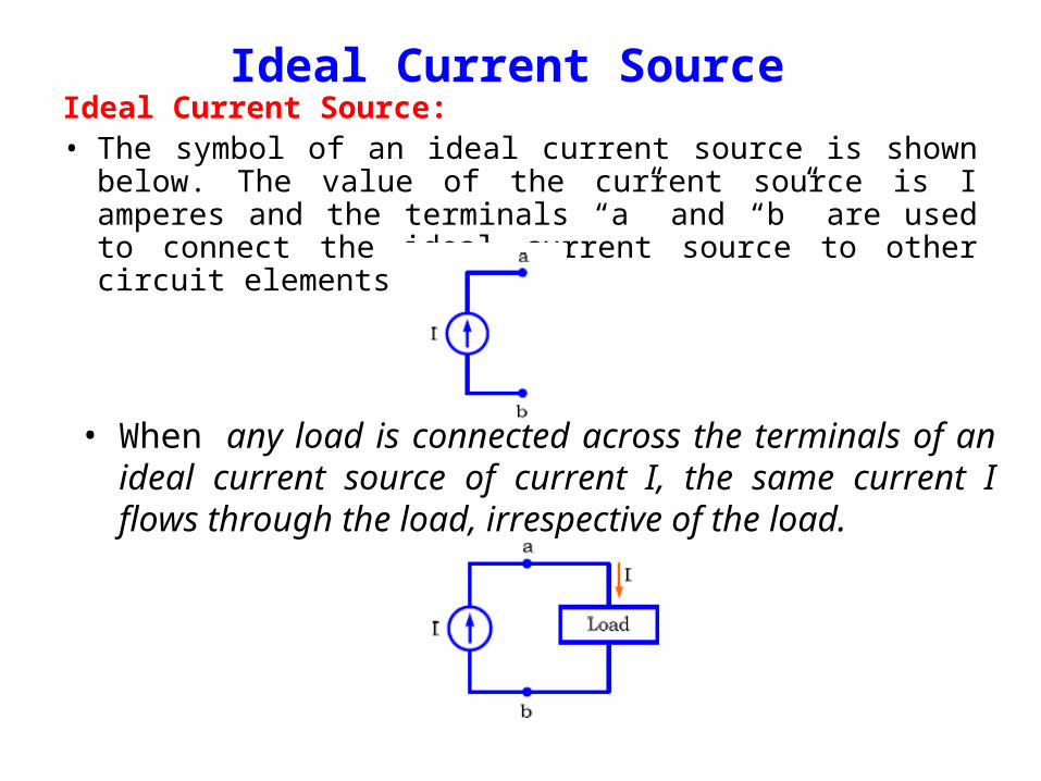
Ideal Current Source: • The symbol of an ideal current source is shown below. The
value of the current source is I amperes and the terminals “a” and “b” are used to connect the ideal current source to other circuit elements.
• When any load is connected across the terminals of an ideal current source of current I, the same current I flows through the load, irrespective of the load.
Ideal Current Source
Ideal Current Source
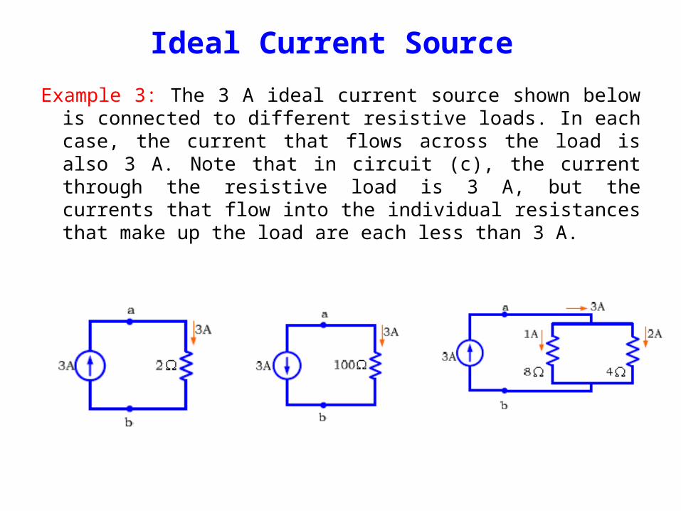
Example 3: The 3 A ideal current source shown below is connected to different resistive loads. In each case, the current that flows across the load is also 3 A. Note that in circuit (c), the current through the resistive load is 3 A, but the currents that flow into the individual resistances that make up the load are each less than 3 A.
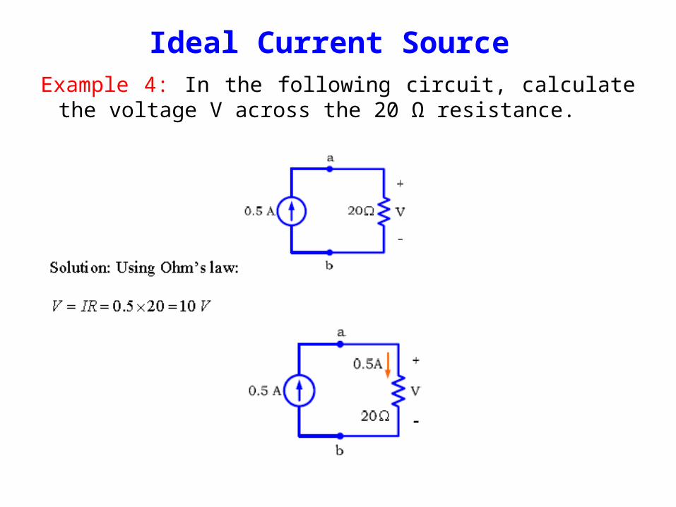
Example 4: In the following circuit, calculate the voltage V across the 20 Ω resistance.
Ideal Current Source
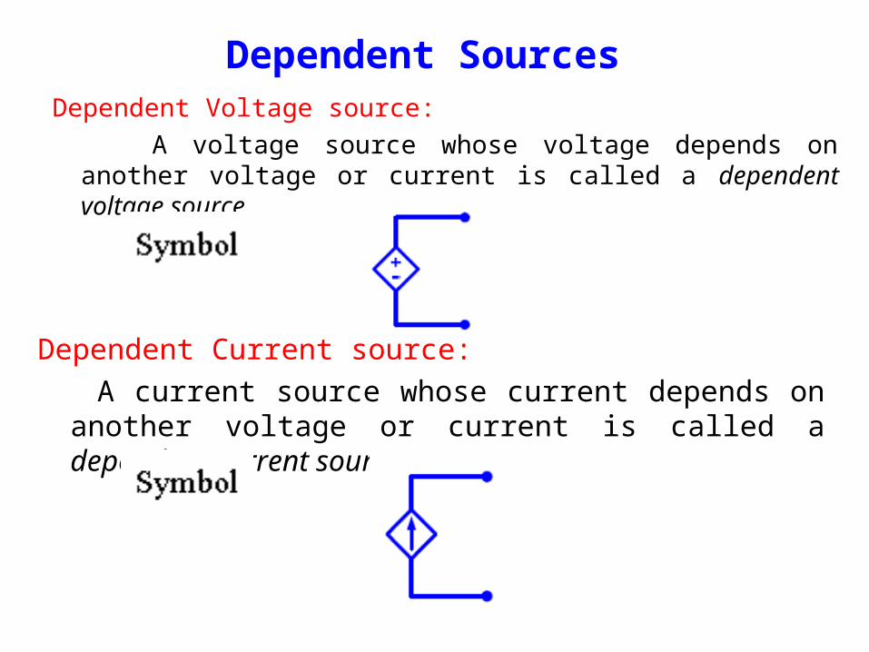
Dependent Sources Dependent Voltage source: A voltage source whose voltage depends on another voltage or
current is called a dependent voltage source.
Dependent Current source: A current source whose current depends on another
voltage or current is called a dependent current source.