Embed Size (px)
Citation preview

HARDWARE MANUAL
FX1N SERIES PROGRAMMABLE CONTROLLERS
FX1N Series Programmable Controllers
Foreword
• This manual contains text, diagrams and explanations which will guide the reader in the correct installationand operation of the FX1N Series Programmable Controllers. It should be read and understood beforeattempting to install or use the unit.
• Further information can be found in the FX Series Programming Manual II.
• If in doubt at any stage of the installation of an FX1N Series Programmable Controller always consult aprofessional electrical engineer who is qualified and trained to the local and national standards which apply tothe installation site.
• If in doubt about the operation or use of FX1N Series Programmable Controller please consult the nearestMitsubisi Electric distributor.
• This manual is subject to change without notice.
i
FX1N Series Programmable Controllers
Hardware Manual
FX1N Series Programmable Controllers
Manual number : JY992D89301
Manual revision :F
Date : April 2001

FX1N Series Programmable Controllers
ii
Guidelines for the safety of the user and protection of the FX 1N.
This manual provides information for the installation and use of the FX1N. The manual hasbeen written to be used by trained and competent personnel. The definition of such a personor persons is as follows;
a) Any engineer who is responsible for the planning, design and construction of automaticequipment using the product associated with this manual should be of a competentnature, (trained and qualified to the local and national standards required to fulfill thatrole). These engineers should be fully aware of all aspects of safety with regards toautomated equipment.
b) Any commissioning or service engineer must be of a competent nature, trained andqualified to the local and national standards required to fulfill that job. These engineersshould also be trained in the use and maintenance of the completed product. Thisincludes being completely familiar with all associated documentation for the saidproduct. All maintenance should be carried out in accordance with established safetypractices.
c) All operators of the completed product should be trained to use that product in a safeand co-ordinated manner in compliance to established safety practices. The operatorsshould also be familiar with documentation which is connected with the actual operationof the completed equipment.
Note : The term ‘completed equipment’ refers to a third party constructed device whichcontains or uses the product associated with this manual.
FX1N Series Programmable Controllers
iii
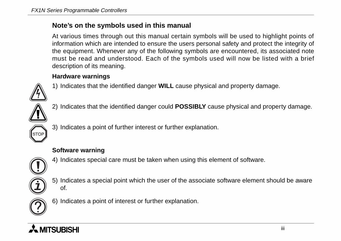
Note’s on the symbols used in this manual
At various times through out this manual certain symbols will be used to highlight points ofinformation which are intended to ensure the users personal safety and protect the integrity ofthe equipment. Whenever any of the following symbols are encountered, its associated notemust be read and understood. Each of the symbols used will now be listed with a briefdescription of its meaning.
Hardware warnings
Software warning
1) Indicates that the identified danger WILL cause physical and property damage.
2) Indicates that the identified danger could POSSIBLY cause physical and property damage.
3) Indicates a point of further interest or further explanation.
4) Indicates special care must be taken when using this element of software.
5) Indicates a special point which the user of the associate software element should be awareof.
6) Indicates a point of interest or further explanation.
FX1N Series Programmable Controllers
iv
• Under no circumstances will Mitsubishi Electric be liable or responsible for any consequentialdamage that may arise as a result of the installation or use of this equipment.
• All examples and diagrams shown in this manual are intended only as an aid to understanding thetext, not to guarantee operation. Mitsubishi Electric will accept no responsibility for actual use of theproduct based on these illustrative examples.
• Owing to the very great variety in possible application of this equipment, you must satisfy yourself asto its suitability for your specific application.
Associated Manuals
The following manuals are recomended as esential reference material for the correct operation of aFX1N series Programmable controller.
Manual Name Manual Number Description
FX Programming Manual II JY992D88101 Programming manual for FX1S, FX1N, FX2N and FX2NCseries Programmable Logic Controllers
FX1N-422-BD Users JY992D84101 Instruction regarding the RS422 interface board
FX1N-485-BD Users JY992D84201 Instruction regarding the RS485 interface board
FX1N-232-BD Users JY992D84401 Instruction regarding the RS232 interface board
FX1N-8AV-BD JY992D84601 Instruction regarding the variable potentiometer input board
FX1N-CNV-BD JY992D84701 Instruction regarding the special adapter board
FX1N-5DM Users JY992D84901 Instruction regarding the display module 5DM
FX1N-4EX-BD Users JY992D95001 Instruction regarding the special input board
FX1N-2EYT-BD Users JY992D95201 Instruction regarding the special output board
FX1N-2AD-BD Users JY992D96201 Instruction regarding the special AD conversion board
FX1N-1DA-BD Users JY992D96401 Instruction regarding the special DA conversion board
v
Table of Contents
Guideline ..............................................................................................ii
1. Introduction............................................................................................1-11.1 World Specification. ............................................................................................. 1-61.2 Model Name ........................................................................................................ 1-71.3 Serial Numbers ................................................................................................... 1-81.4 Configuration ....................................................................................................... 1-9
1.4.1 Input/Output Points and Current Consumption ....................................................... 1-111.4.2 Rules of Expansion ................................................................................................. 1-13
1.5 Back up Data ..................................................................................................... 1-141.5.1 EEPROM backup .................................................................................................... 1-141.5.2 Capacitor backup .................................................................................................... 1-14
2. Terminal layouts ....................................................................................2-12.1 AC Powered Main Units ...................................................................................... 2-12.2 DC Powered Main Units ...................................................................................... 2-42.3 FX2N and FX0N Extension blocks ....................................................................... 2-7
FX1N Series Programmable Controllers
FX1N Series Programmable Controllers
vi
3. Installation Notes...................................................................................3-13.1 Product Outline.................................................................................................... 3-23.2 FX1N RUN/STOP Control .................................................................................... 3-43.3 General Specifications......................................................................................... 3-53.4 PLC Mounting Arrangements .............................................................................. 3-63.5 DIN Rail Mounting ............................................................................................... 3-73.6 Direct Mounting .................................................................................................. 3-83.7 Termination at Screw Terminals ........................................................................ 3-103.8 Wiring Techniques............................................................................................. 3-113.9 Installing Optional Units..................................................................................... 3-12
3.9.1 Special Function Boards ......................................................................................... 3-123.9.2 FX1N-5DM Display Module ..................................................................................... 3-14
4. Power Supply ........................................................................................4-14.1 Wiring Techniques............................................................................................... 4-14.2 Wiring Cautions ................................................................................................... 4-14.3 Power Supply ...................................................................................................... 4-14.4 Power Requirements .......................................................................................... 4-24.5 Example Wiring ................................................................................................... 4-3
4.5.1 AC Power supply ....................................................................................................... 4-34.5.2 DC Power supply....................................................................................................... 4-4
4.6 Service Power supply .......................................................................................... 4-64.7 Earthing / Grounding ........................................................................................... 4-6
FX1N Series Programmable Controllers
vii
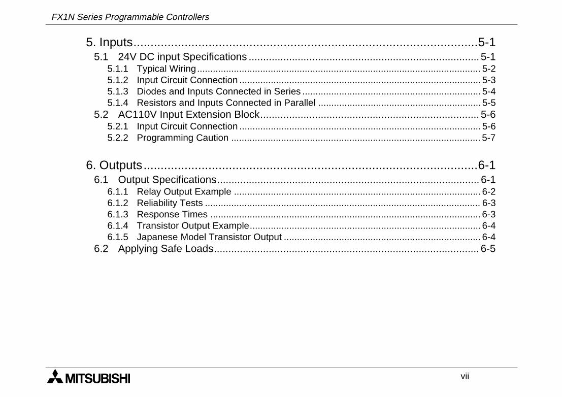
5. Inputs.....................................................................................................5-15.1 24V DC input Specifications ................................................................................ 5-1
5.1.1 Typical Wiring............................................................................................................ 5-25.1.2 Input Circuit Connection ............................................................................................ 5-35.1.3 Diodes and Inputs Connected in Series .................................................................... 5-45.1.4 Resistors and Inputs Connected in Parallel .............................................................. 5-5
5.2 AC110V Input Extension Block............................................................................ 5-65.2.1 Input Circuit Connection ............................................................................................ 5-65.2.2 Programming Caution ............................................................................................... 5-7
6. Outputs..................................................................................................6-16.1 Output Specifications........................................................................................... 6-1
6.1.1 Relay Output Example .............................................................................................. 6-26.1.2 Reliability Tests ......................................................................................................... 6-36.1.3 Response Times ....................................................................................................... 6-36.1.4 Transistor Output Example........................................................................................ 6-46.1.5 Japanese Model Transistor Output ........................................................................... 6-4
6.2 Applying Safe Loads............................................................................................ 6-5
FX1N Series Programmable Controllers
viii
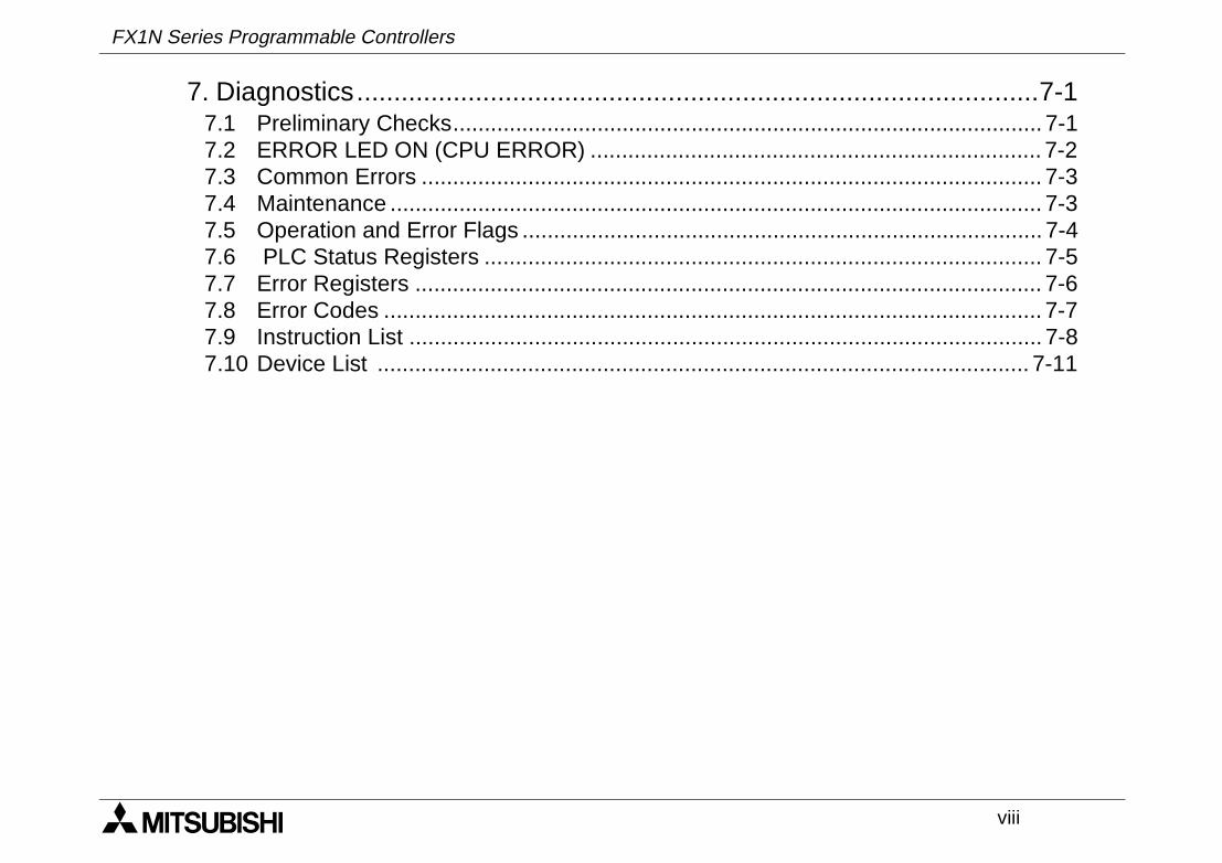
7. Diagnostics............................................................................................7-17.1 Preliminary Checks.............................................................................................. 7-17.2 ERROR LED ON (CPU ERROR) ........................................................................ 7-27.3 Common Errors ................................................................................................... 7-37.4 Maintenance ........................................................................................................ 7-37.5 Operation and Error Flags ................................................................................... 7-47.6 PLC Status Registers ......................................................................................... 7-57.7 Error Registers .................................................................................................... 7-67.8 Error Codes ......................................................................................................... 7-77.9 Instruction List ..................................................................................................... 7-87.10 Device List ........................................................................................................ 7-11
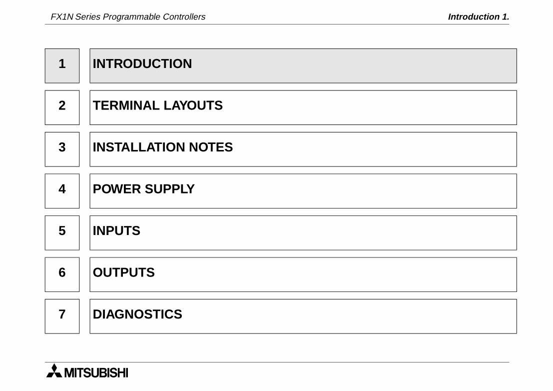
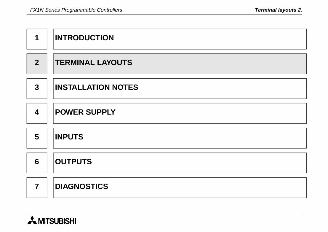
1 INTRODUCTION
2 TERMINAL LAYOUTS
3 INSTALLATION NOTES
4 POWER SUPPLY
5 INPUTS
6 OUTPUTS
7 DIAGNOSTICS
FX1N Series Programmable Controllers Introduction 1.

FX1N Series Programmable Controllers Introduction 1.
Introduction 1.
1-1
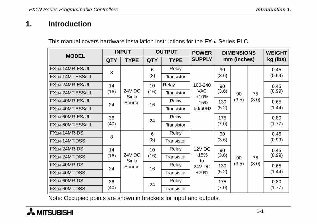
1. Introduction
This manual covers hardware installation instructions for the FX1N Series PLC.
Note: Occupied points are shown in brackets for input and outputs.
MODELINPUT OUTPUT POWER
SUPPLYDIMENSIONSmm (inches)
WEIGHTkg (lbs)QTY TYPE QTY TYPE
FX1N-14MR-ES/UL8
24V DCSink/
Source
6(8)
Relay
100-240 VAC
+10% -15%
50/60Hz
90(3.6)
90(3.5)
75(3.0)
0.45 (0.99)FX1N-14MT-ESS/UL Transistor
FX1N-24MR-ES/UL 14(16)
10(16)
Relay 90(3.6)
0.45(0.99)FX1N-24MT-ESS/UL Transistor
FX1N-40MR-ES/UL24 16
Relay 130(5.2)
0.65(1.44)FX1N-40MT-ESS/UL Transistor
FX1N-60MR-ES/UL 36(40)
24Relay 175
(7.0)0.80
(1.77)FX1N-60MT-ESS/UL Transistor
FX1N-14MR-DS8
24V DCSink/
Source
6(8)
Relay
12V DC-15%
to24V DC+20%
90(3.6)
90(3.5)
75(3.0)
0.45 (0.99)FX1N-14MT-DSS Transistor
FX1N-24MR-DS 14(16)
10(16)
Relay 90(3.6)
0.45(0.99)FX1N-24MT-DSS Transistor
FX1N-40MR-DS24 16
Relay 130(5.2)
0.65(1.44)FX1N-40MT-DSS Transistor
FX1N-60MR-DS 36(40)
24Relay 175
(7.0)0.80
(1.77)FX1N-60MT-DSS Transistor
FX1N Series Programmable Controllers
FX1N Series Programmable Controllers Introduction 1.
1-2
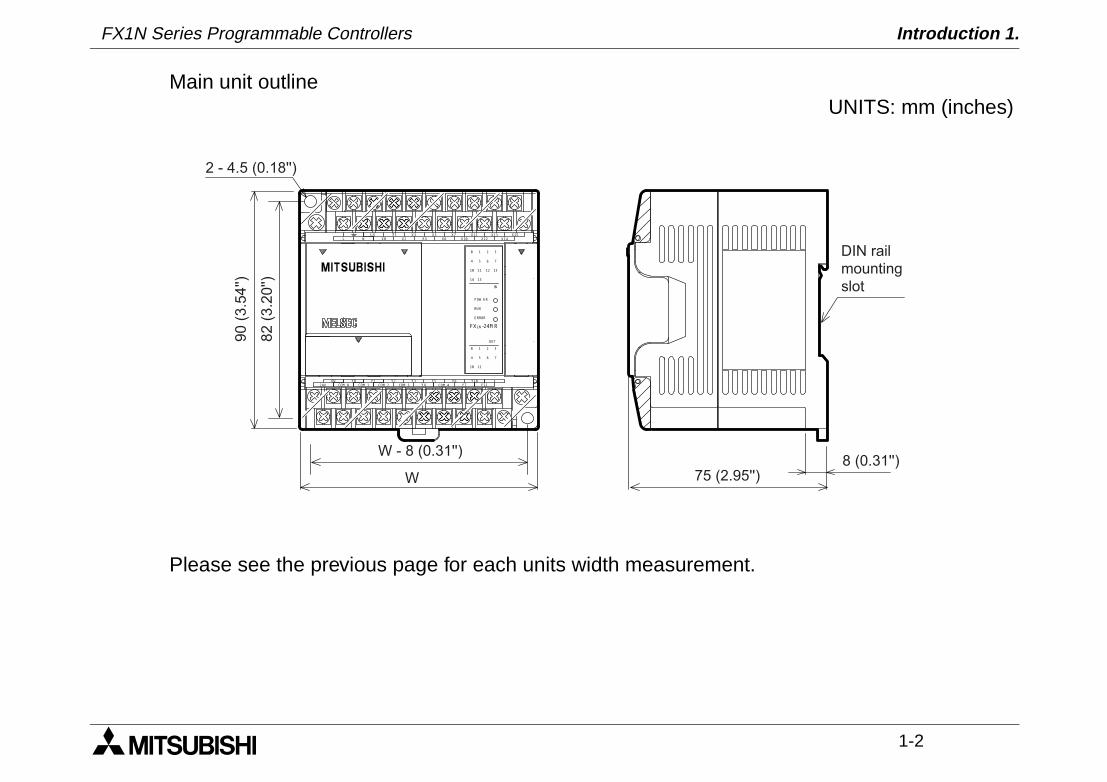
Main unit outline
Please see the previous page for each units width measurement.
N X14
24V Y7
Y6Y0
FX1N-24M R
X0 X2
X1 X3 X5
X4
X7
X6
X11
X10
S/S X13
X12
X15
L
0V
Y11COM 2 COM 4
Y10Y5
Y4
Y2Y1
COM 0 COM 1 COM 3
Y3
POW ER
ERROR
IN
OUT
0 1 2 3
0 1 2 3
RUN
4 5 6 7
4 5 6 7
1110
131110 12
14 15
W
W - 8 (0.31'')
82(3.20'')
90(3.54'')
75 (2.95'')8 (0.31'')
DIN rail
mounting
slot
2 - 4.5 (0.18'')
UNITS: mm (inches)
FX1N Series Programmable Controllers Introduction 1.
1-3
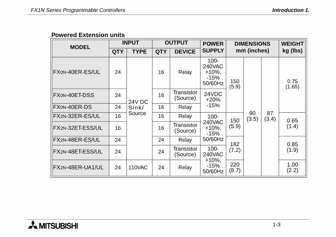
Powered Extension units
MODELINPUT OUTPUT POWER
SUPPLYDIMENSIONSmm (inches)
WEIGHTkg (lbs)QTY TYPE QTY DEVICE
FX0N-40ER-ES/UL 24
24V DCSink /Source
16 Relay
100-240VAC +10%, -15%
50/60Hz 150 (5.9)
90(3.5)
87(3.4)
0.75 (1.65)
FX0N-40ET-DSS 24 16 Transistor(Source)
24VDC +20% -15%FX0N-40ER-DS 24 16 Relay
FX2N-32ER-ES/UL 16 16 Relay 100-240VAC +10%, -15%
50/60Hz
150(5.9)
0.65(1.4)FX2N-32ET-ESS/UL 16 16 Transistor
(Source)
FX2N-48ER-ES/UL 24 24 Relay182(7.2)
0.85(1.9)FX2N-48ET-ESS/UL 24 24 Transistor
(Source)100-
240VAC +10%, -15%
50/60HzFX2N-48ER-UA1/UL 24 110VAC 24 Relay 220
(8.7)1.00(2.2)
FX1N Series Programmable Controllers Introduction 1.
1-4
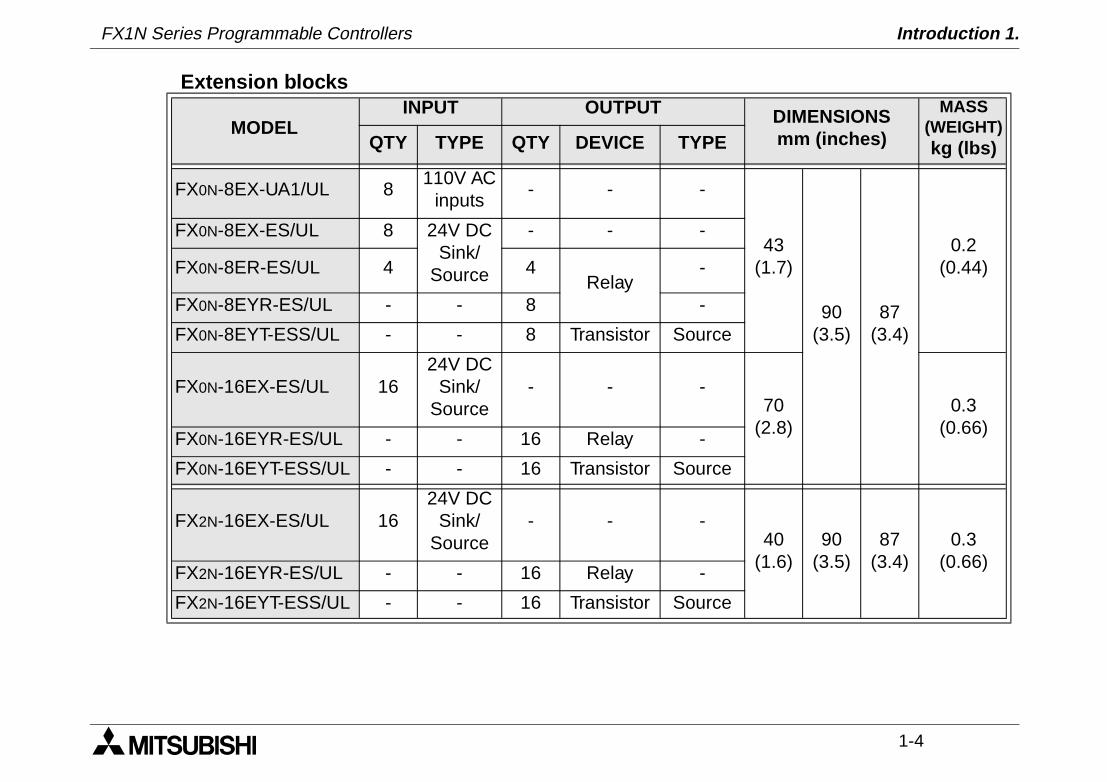
Extension blocks
MODELINPUT OUTPUT DIMENSIONS
mm (inches)
MASS (WEIGHT)kg (lbs)QTY TYPE QTY DEVICE TYPE
FX0N-8EX-UA1/UL 8110V AC
inputs- - -
43(1.7)
90(3.5)
87(3.4)
0.2(0.44)
FX0N-8EX-ES/UL 8 24V DCSink/
Source
- - -
FX0N-8ER-ES/UL 4 4Relay
-
FX0N-8EYR-ES/UL - - 8 -
FX0N-8EYT-ESS/UL - - 8 Transistor Source
FX0N-16EX-ES/UL 1624V DC
Sink/Source
- - -70
(2.8)0.3
(0.66)FX0N-16EYR-ES/UL - - 16 Relay -
FX0N-16EYT-ESS/UL - - 16 Transistor Source
FX2N-16EX-ES/UL 1624V DC
Sink/Source
- - -40
(1.6)90
(3.5)87
(3.4)0.3
(0.66)FX2N-16EYR-ES/UL - - 16 Relay -
FX2N-16EYT-ESS/UL - - 16 Transistor Source
FX1N Series Programmable Controllers Introduction 1.
1-5
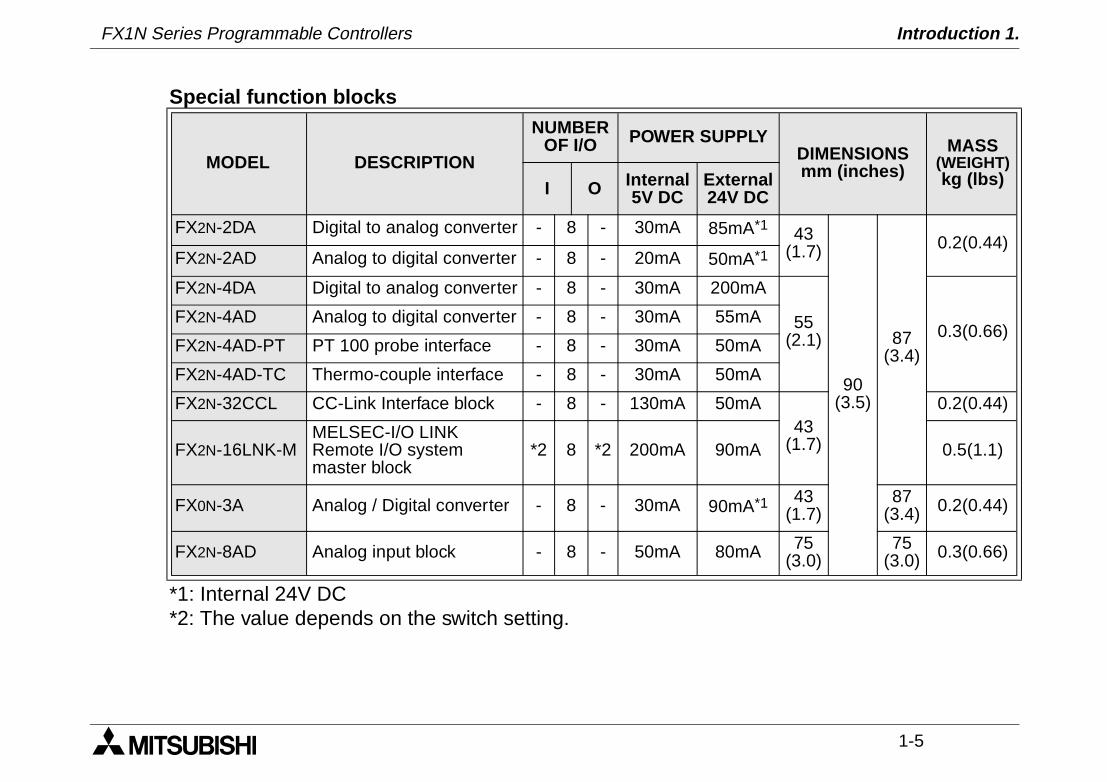
*1: Internal 24V DC*2: The value depends on the switch setting.
Special function blocks
MODEL DESCRIPTION
NUMBEROF I/O POWER SUPPLY
DIMENSIONSmm (inches)
MASS (WEIGHT)kg (lbs)I O Internal
5V DCExternal24V DC
FX2N-2DA Digital to analog converter - 8 - 30mA 85mA*1 43(1.7)
90(3.5)
87(3.4)
0.2(0.44)FX2N-2AD Analog to digital converter - 8 - 20mA 50mA*1
FX2N-4DA Digital to analog converter - 8 - 30mA 200mA
55(2.1) 0.3(0.66)
FX2N-4AD Analog to digital converter - 8 - 30mA 55mA
FX2N-4AD-PT PT 100 probe interface - 8 - 30mA 50mA
FX2N-4AD-TC Thermo-couple interface - 8 - 30mA 50mA
FX2N-32CCL CC-Link Interface block - 8 - 130mA 50mA43
(1.7)
0.2(0.44)
FX2N-16LNK-MMELSEC-I/O LINK Remote I/O system master block
*2 8 *2 200mA 90mA 0.5(1.1)
FX0N-3A Analog / Digital converter - 8 - 30mA 90mA*1 43(1.7)
87(3.4) 0.2(0.44)
FX2N-8AD Analog input block - 8 - 50mA 80mA 75(3.0)
75(3.0) 0.3(0.66)
FX1N Series Programmable Controllers Introduction 1.
1-6
Special Function Boards
1.1 World Specification.
MODEL DESCRIPTIONNUMBER
OF I/O DIMENSIONS
I O
FX1N-4EX-BD Four point special input - 0 -
Mounts directly into top of PLC
FX1N-2EYT-BD Two point special output - 0 -
FX1N-2AD-BD Two channe l spec ia lanalog to digital converter - 0 -
FX1N-1DA-BD One channe l spec ia ldigital to analog converter - 0 -
Input Sink / Source
World spec models : SINK / SOURCE.Japanese models : ALWAYS SINK.
OutputsTransistor
World spec models : ALWAYS SOURCE.Japanese models : ALWAYS SINK.

FX1N Series Programmable Controllers Introduction 1.
1-7
1.2 Model Name
Notes on model name
Note: *1. World spec FX1N DC type main units have not yet recieved official UL certification.*1. FX0N series extension units do not have UL certification.*2. FX0N series extension units do not have CE certification.
F X 1 N - 2 4 M R - D S / ¨
C)
A)B) E)
D)
F)
A) PLC type : FX1N
B) Total number of I / O channels
C)
Unit type
M MPU - main unit
E Powered extension unit
EX Extension block, input
EY Extension block, output
D)
Output type
R Relay
T Transistor
S Triac (SSR)
E)
Features
Omit AC, Japanese spec.
D DC Japanese spec.
DS DC World spec, CE & UL registered *1.
DSS DC World spec. DC source transistor, CE & ULregistered *1.
E AC, Japanese spec.
ES AC, World spec, CE registered.
ESS AC World spec. DC source transistor, CEregistered.
UA1 AC Power Supply, AC inputs, CE registered. *2
F) UL UL registered
FX1N Series Programmable Controllers Introduction 1.
1-8
1.3 Serial Numbers
Notes on serial numbers1) Production year
2) Production month
3) Production serial number
S E R I A L N O. : 0 6 3 2 6 73)1)
2)e.g. 0=2000 1=2001 1 - 9 = Jan - Sept
X = OctY = NovZ = Dec
FX1N Series Programmable Controllers Introduction 1.
1-9
1.4 Configuration
Schematic system
B
FX1N-5DMFX1N-EEPROM-8L
FX1N-232-BDFX1N-422-BDFX1N-485-BDFX1N-CNV-BDFX1N-8AV-BD
A
C
1
2
3
D
RS 422/RS 232 CONVERTERFX-232AW(C)
F
FX-10P-E FX-20P-EH
MELSEC MEDOCFX-PCS/AT-EEMELSEC MEDOC PLUS
FX-PCS/WIN-E
E
FXON-232ADP*FXON-485ADP**used withFX1N-CNV-BD
FX-10DU-E FX-40DU-ESFX-20DU-E FX-40DU-TK -ESFX-25DU-E FX-50DU-TKS-EFX-30DU-E
FX-10DM-E F940GOTF930GOT F940WGOT
G
1
J
FX2N-16EX-ES/ULFX2N-16EYR-ES/ULFX2N-16EYT-ESS/UL
FX0N-8EX-ES/ULFX0N-8EX-UA1/ULFX0N-8ER-ES/ULFX0N-8EYR-ES/ULFX0N-8EYT-ESS/ULFX0N-16EX-ES/ULFX0N-16EYR-ES/ULFX0N-16EYT-ESS/UL
K
FX2N-2DA
FX2N-4DAFX2N-2AD
FX2N-4ADFX2N-4AD-PTFX2N-4AD-TC
FX2N-32CCLFX2N-16LNK-M
FX0N-3A
I
FX0N-40ER-ES/ULFX0N-40ET-DSSFX0N-40ER-DS
FX2N-32ER-ES/ULFX2N-32ET-ESS/ULFX2N-48ER-ES/UL
4
FX2N-48ER-UA1/ULFX2N-48ET-ESS/UL
FX2N-8AD
GX Developer
FX1N-4EX-BDFX1N-2EYT-BDFX1N-2AD-BDFX1N-1DA-BD
FX1N-14MR-ES/UL
FX1N-40MR-ES/UL
FX1N-60MR-ES/UL
FX1N-14MT-DSSFX1N-24MT-DSSFX1N-40MT-DSSFX1N-60MT-DSSFX1N-14MR-DSFX1N-24MR-DSFX1N-40MR-DSFX1N-60MR-DS
FX1N-24MT-ESS/UL
FX1N-40MT-ESS/UL
FX1N-24MR-ES/UL
FX0N-32NT-DP
FX2N-16CCL-M
FX1N-14MT-ESS/UL
FX1N-60MT-ESS/UL
FX1N Series Programmable Controllers Introduction 1.
1-10
Configuration notesA MPU-Main unit (Main Processing Unit)
B FX1N Memory cassette or Display Module
C FX1N Expansion boards
D FX0N Network adapters
E Programming cables
F Programming software
G HMI devices, F900GOT, FX-DU Series
H Dedicated programming tools
I Powered extension units
J Extension blocks
K Special function blocks
Memory port
Extension board port
Programming port
MPU bus port
FX1N Series Programmable Controllers Introduction 1.
1-11
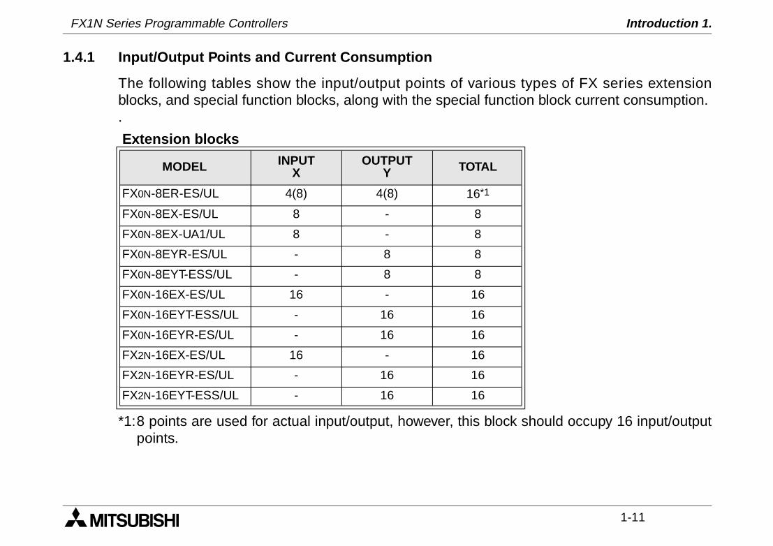
1.4.1 Input/Output Points and Current Consumption
The following tables show the input/output points of various types of FX series extensionblocks, and special function blocks, along with the special function block current consumption..
*1:8 points are used for actual input/output, however, this block should occupy 16 input/outputpoints.
Extension blocks
MODEL INPUTX
OUTPUTY TOTAL
FX0N-8ER-ES/UL 4(8) 4(8) 16*1
FX0N-8EX-ES/UL 8 - 8
FX0N-8EX-UA1/UL 8 - 8
FX0N-8EYR-ES/UL - 8 8
FX0N-8EYT-ESS/UL - 8 8
FX0N-16EX-ES/UL 16 - 16
FX0N-16EYT-ESS/UL - 16 16
FX0N-16EYR-ES/UL - 16 16
FX2N-16EX-ES/UL 16 - 16
FX2N-16EYR-ES/UL - 16 16
FX2N-16EYT-ESS/UL - 16 16
FX1N Series Programmable Controllers Introduction 1.
1-12
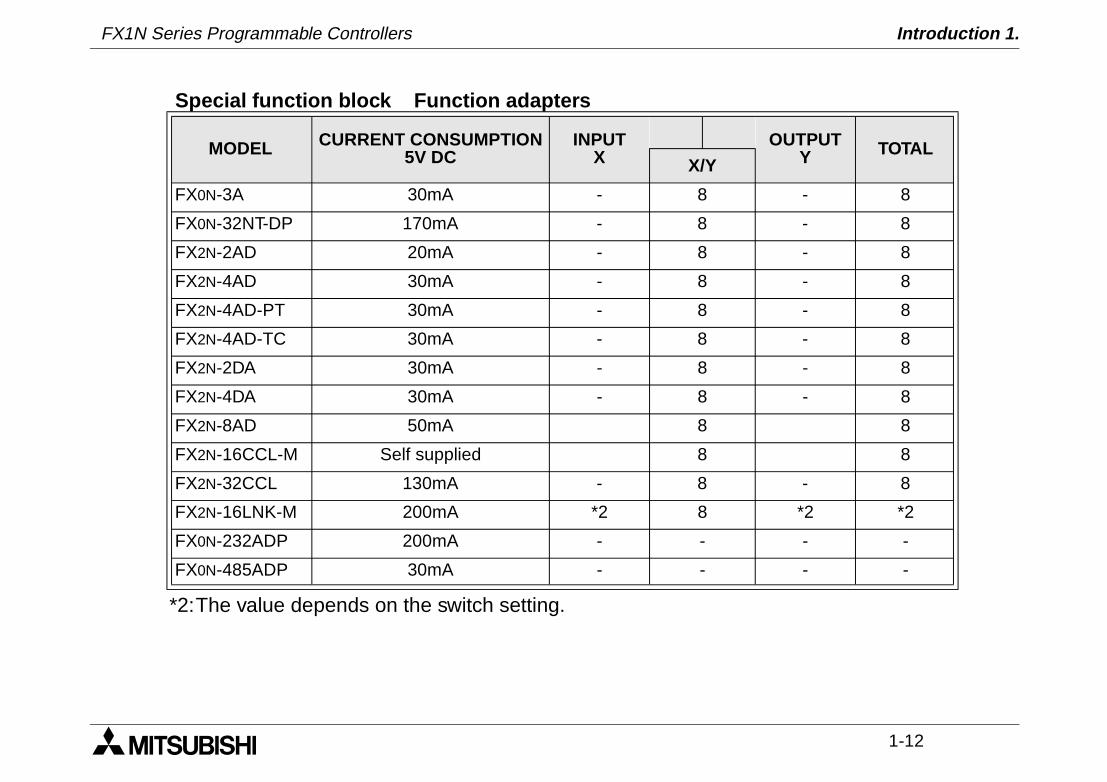
*2:The value depends on the switch setting.
Special function block Function adapters
MODEL CURRENT CONSUMPTION5V DC
INPUTX
OUTPUTY TOTAL
X/Y
FX0N-3A 30mA - 8 - 8
FX0N-32NT-DP 170mA - 8 - 8
FX2N-2AD 20mA - 8 - 8
FX2N-4AD 30mA - 8 - 8
FX2N-4AD-PT 30mA - 8 - 8
FX2N-4AD-TC 30mA - 8 - 8
FX2N-2DA 30mA - 8 - 8
FX2N-4DA 30mA - 8 - 8
FX2N-8AD 50mA 8 8
FX2N-16CCL-M Self supplied 8 8
FX2N-32CCL 130mA - 8 - 8
FX2N-16LNK-M 200mA *2 8 *2 *2
FX0N-232ADP 200mA - - - -
FX0N-485ADP 30mA - - - -
FX1N Series Programmable Controllers Introduction 1.
1-13
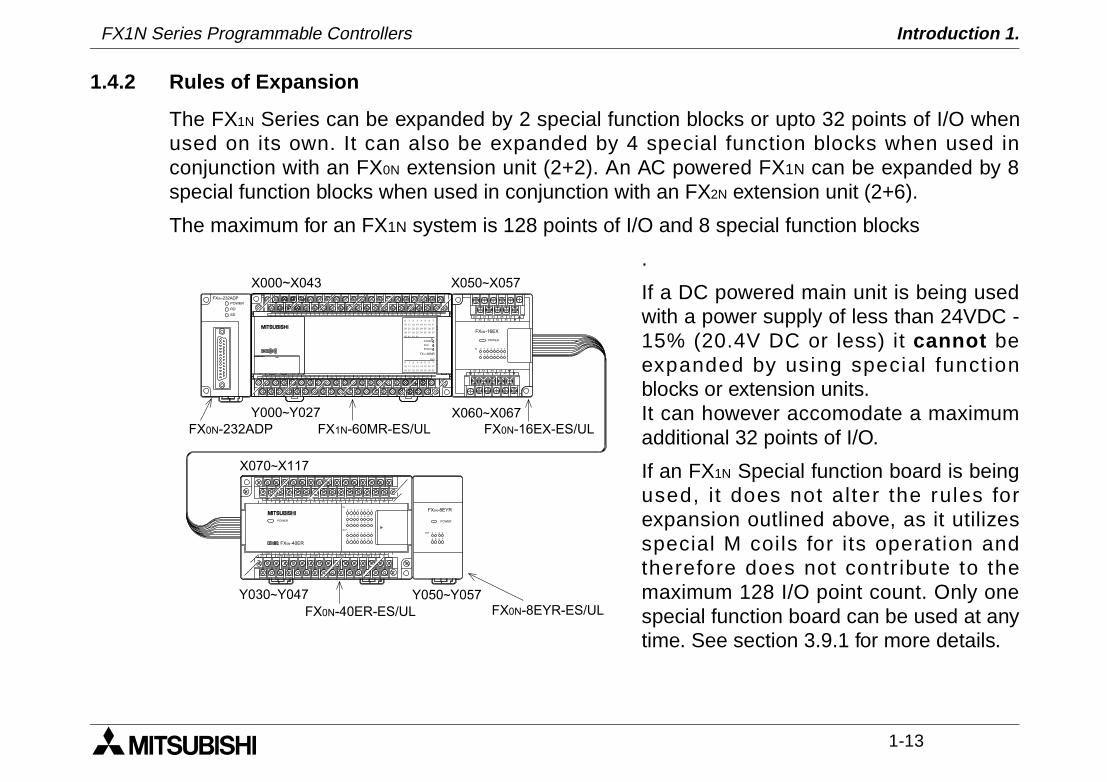
1.4.2 Rules of Expansion
The FX1N Series can be expanded by 2 special function blocks or upto 32 points of I/O whenused on its own. It can also be expanded by 4 special function blocks when used inconjunction with an FX0N extension unit (2+2). An AC powered FX1N can be expanded by 8special function blocks when used in conjunction with an FX2N extension unit (2+6).
The maximum for an FX1N system is 128 points of I/O and 8 special function blocks
.
If a DC powered main unit is being usedwith a power supply of less than 24VDC -15% (20.4V DC or less) it cannot beexpanded by using special functionblocks or extension units. It can however accomodate a maximumadditional 32 points of I/O.
If an FX1N Special function board is beingused, it does not alter the rules forexpansion outlined above, as it utilizesspecial M coils for its operation andtherefore does not contr ibute to themaximum 128 I/O point count. Only onespecial function board can be used at anytime. See section 3.9.1 for more details.
Y7COM0 COM1 COM2 Y3 COM3 Y5 Y7 COM4 Y1 Y3 COM5 Y524+COM Y0 Y1 Y2 Y4 Y6 Y0 Y2 Y4 Y6
X7X3 X5N X0 X2 X4 X6L
COM COM X1
POWER
OUT
0 7654321
IN
0 1 2 3 4 5 6 7
X1X0 X2
X3X4
X5 X7X6
X1X0 X2
X3X4
X5 X7X6
0 1 2 3 4 5 6 7
0 1 2 3 4 5 6 7
0 1 2 3 4 5 6 7 POWER
OUT
4 765
3210
RD
SD
POWER
24+ X1 X3 X5 X7X0 X2 X4 X6
X0X1
X2 X4 X6X3 X5 X7
POWER
7
7
0
IN
1
1
2
2
3
3
4
4
5
5
6
60
FX0N-16EX
FX0N-40ER
FX0N-8EYR
FX0N-232ADP
X000~X043 X050~X057
Y000~Y027 X060~X067
X070~X117
Y030~Y047 Y050~Y057
POWER
ERROR
IN
OUT
0 1 2 3
0 1 2 3
RUN
4 5 6 7
4 5 6 7
1716
373534 36
10 11 12 13 14 15 16 17
40 41 42 43
14 1510 11 12 13
272524 2620 21 22 23
30 31 32 33
272624 2520 21 22 23
COM2 Y5Y6
24+Y0 Y2Y1
COM0 COM1 COM3Y3Y4
Y17Y11
COMX10
X13 X43X42X12L N X0 X2
X1 X3 X5X4
X7X6
X11 X15X14 X16
X21X20
X23 X25X24
Y7Y10
Y27Y12 Y14
COM7COM4
X27X26
X31X30
X33X32
X35X34
X37X36
X41X40
Y16Y15
Y20 Y22Y21
Y24 Y26COM6
X17
FX1N-60MR
COMY13 COM5 Y23 Y25
X22
FX0N-232ADP FX1N-60MR-ES/UL FX0N-16EX-ES/UL
FX0N-40ER-ES/UL FX0N-8EYR-ES/UL
FX1N Series Programmable Controllers Introduction 1.
1-14
1.5 Back up Data
1.5.1 EEPROM backup
Data includes the Program, Comment, File Registers (D1000 ~ D7999), and parameter data.This will be stored as long as the EEPROM is not damaged.
If the PLC has been powered up for five minutes or more, the following data will be saved inthe EEPROM at powerdown:
S10 ~ S127, M384 ~ M511, C16 ~ C31, and D128 ~ D255.
1.5.2 Capacitor backup
The capacitor backed memory includes M512 ~ M1535, S128 ~ S999, T240 ~ T255, C32 ~ C199, C220 ~ C234, and D256 ~ D7999 and the RTC.
The capacitor backed memory will retain programs for a maximum of 10 days, and requires 30minutes to recharge upon power up.
Note : The FX1N does not have battery backup, if a system requires backup of more than 10days, a peripheral backup power source must be provided.
1 INTRODUCTION
2 TERMINAL LAYOUTS
3 INSTALLATION NOTES
4 POWER SUPPLY
5 INPUTS
6 OUTPUTS
7 DIAGNOSTICS
FX1N Series Programmable Controllers Terminal layouts 2.
FX1N Series Programmable Controllers Terminal layouts 2.
Terminal layouts 2.
2-1
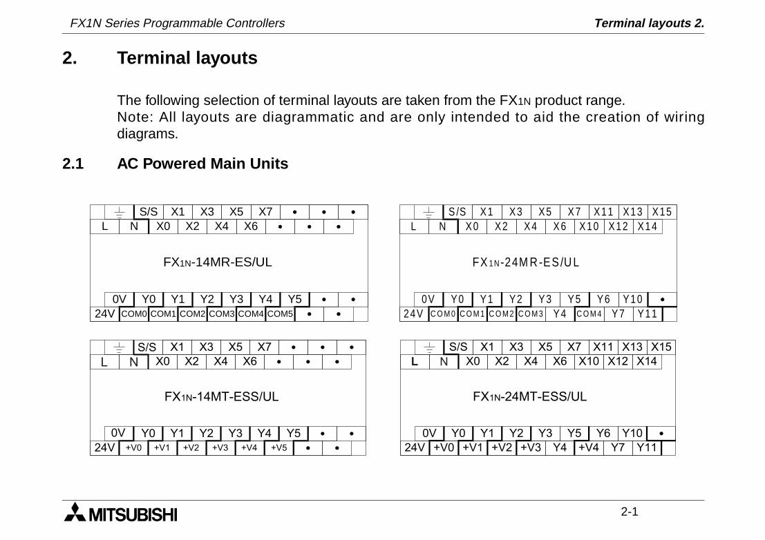
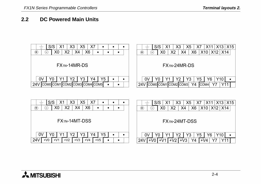
2. Terminal layouts
The following selection of terminal layouts are taken from the FX1N product range. Note: All layouts are diagrammatic and are only intended to aid the creation of wiringdiagrams.
2.1 AC Powered Main Units
S/S X1N X0 X4
FX1N-14MR-ES/UL
X5
0V Y0 Y1 Y2 Y3
X3X2
24V COM0 COM1 COM3COM2
LX7
X6
Y4COM4 COM5
Y5
S /S X1N X0 X4
FX 1N-24M R -ES /U L
X5
0V Y0 Y1 Y2 Y3
X3X2
24V C O M 0 C O M 1 C O M 3C O M 2
LX7
X6
Y5C O M 4
X12X13X11
X10X15
X14
Y6Y4
Y10Y7 Y11
S/S X1
X0 X4
X5
0V Y0 Y1 Y2 Y3
X3
X2
24V
X7
X6
Y5
X12
X13X11
X10
X15
X14
Y6 Y10
Y7 Y11+V0 +V1 +V2 +V3 Y4 +V4
FX1N-24MT-ESS/UL
NL
S/S X1
X0 X4
X5
0V Y0 Y1 Y2 Y3
X3
X2
24V +V0 +V1 +V3+V2
X7
X6
Y4
+V4 +V5
Y5
FX1N-14MT-ESS/UL
NL
FX1N Series Programmable Controllers

FX1N Series Programmable Controllers Terminal layouts 2.
2-2
S /S X1N X0 X4
FX 1N-40M R -ES /U L
X5
0V Y0 Y1 Y2Y3
X3X2
24V C O M 0 C O M 1 C O M 3C O M 2
LX7
X6
Y5 C O M 4
X12X13X11
X10X15
X14
Y6Y4 Y14Y7 Y11
X20X21X17
X16X23
X22 X24X25
X26X27
Y10 Y12Y13 C O M 5
Y16Y15 Y17
S/S X1
X0 X4
FX1N-40MT-ESS/UL
X5
0V Y0 Y1 Y2
X3
X2
24V
X7
X6
Y5
X12
X13X11
X10
X15
X14
Y6Y4 Y14
Y7 Y11
X20
X21X17
X16
X23
X22 X24
X25
X26
X27
Y10 Y12
Y13
Y16
Y15 Y17+V0 +V1 +V2 +V3 +V4 +V5Y3
NL

FX1N Series Programmable Controllers Terminal layouts 2.
2-3
S /S X1N X0 X4
FX 1N-60M R -ES/U L
X5
0V Y0 Y1 Y2Y3
X3X2
24V C O M 0 C O M 1 C O M 3C O M 2
LX7
X6
Y5 C O M 4
X12X13X11
X10X15
X14
Y6Y4 Y14Y7 Y11
X20X21X17
X16X23
X22 X24X25
X26X27
Y10 Y12Y13 C O M 5
Y16Y15 Y17
X31X30 X32
X33X34
X35X40
X41X42
X43
Y20 Y22Y21 Y23C O M 6
Y24 Y26Y25 Y27C O M 7
X36X37
S/S X1
X0 X4
FX1N-60MT-ESS/UL
X5
0V Y0 Y1 Y2
Y3
X3
X2
24V
X7
X6
Y5
X12
X13X11
X10
X15
X14
Y6Y4 Y14
Y7 Y11
X20
X21X17
X16
X23
X22 X24
X25
X26
X27
Y10 Y12
Y13
Y16
Y15 Y17
X31
X30 X32
X33
X34
X35
X40
X41
X42
X43
Y20 Y22
Y21 Y23
Y24 Y26
Y25 Y27
X36
X37
+V0 +V1 +V2 +V3 +V4 +V5 +V6 +V7
NL
FX1N Series Programmable Controllers Terminal layouts 2.
2-4
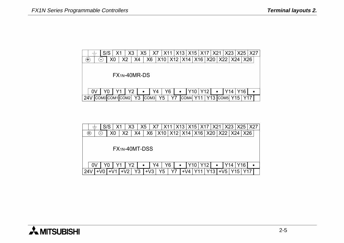
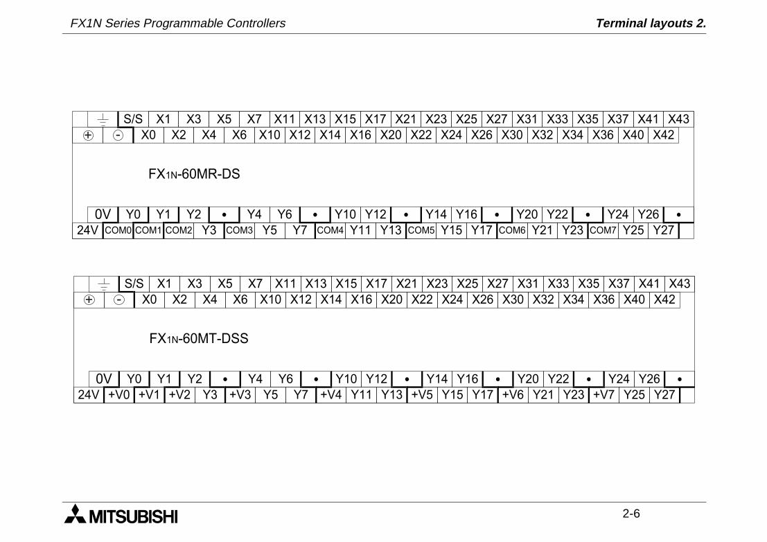
2.2 DC Powered Main Units
S/S X1
X0 X4
FX1N-14MR-DS
X5
0V Y0 Y1 Y2 Y3
X3
X2
24V COM0 COM1 COM3COM2
X7
X6
Y4
COM4 COM5
Y5
-+
S/S X1
X0 X4
X5
0V Y0 Y1 Y2 Y3
X3
X2
24V +V0 +V1 +V3+V2
X7
X6
Y4
+V4 +V5
Y5
FX1N-14MT-DSS
-+
S/S X1
X0 X4
FX1N-24MR-DS
X5
0V Y0 Y1 Y2 Y3
X3
X2
24V COM0 COM1 COM3COM2
X7
X6
Y5
COM4
X12
X13X11
X10
X15
X14
Y6
Y4
Y10
Y7 Y11
-+
S/S X1
X0 X4
X5
0V Y0 Y1 Y2 Y3
X3
X2
24V
X7
X6
Y5
X12
X13X11
X10
X15
X14
Y6 Y10
Y7 Y11+V0 +V1 +V2 +V3 Y4 +V4
FX1N-24MT-DSS
-+
FX1N Series Programmable Controllers Terminal layouts 2.
2-5
S/S X1
X0 X4
FX1N-40MR-DS
X5
0V Y0 Y1 Y2
Y3
X3
X2
24V COM0 COM1 COM3COM2
X7
X6
Y5 COM4
X12
X13X11
X10
X15
X14
Y6Y4 Y14
Y7 Y11
X20
X21X17
X16
X23
X22 X24
X25
X26
X27
Y10 Y12
Y13 COM5
Y16
Y15 Y17
-+
S/S X1
X0 X4
FX1N-40MT-DSS
X5
0V Y0 Y1 Y2
X3
X2
24V
X7
X6
Y5
X12
X13X11
X10
X15
X14
Y6Y4 Y14
Y7 Y11
X20
X21X17
X16
X23
X22 X24
X25
X26
X27
Y10 Y12
Y13
Y16
Y15 Y17+V0 +V1 +V2 +V3 +V4 +V5Y3
-+
FX1N Series Programmable Controllers Terminal layouts 2.
2-6
S/S X1
X0 X4
FX1N-60MR-DS
X5
0V Y0 Y1 Y2
Y3
X3
X2
24V COM0 COM1 COM3COM2
X7
X6
Y5 COM4
X12
X13X11
X10
X15
X14
Y6Y4 Y14
Y7 Y11
X20
X21X17
X16
X23
X22 X24
X25
X26
X27
Y10 Y12
Y13 COM5
Y16
Y15 Y17
X31
X30 X32
X33
X34
X35
X40
X41
X42
X43
Y20 Y22
Y21 Y23COM6
Y24 Y26
Y25 Y27COM7
X36
X37
-+
S/S X1
X0 X4
FX1N-60MT-DSS
X5
0V Y0 Y1 Y2
Y3
X3
X2
24V
X7
X6
Y5
X12
X13X11
X10
X15
X14
Y6Y4 Y14
Y7 Y11
X20
X21X17
X16
X23
X22 X24
X25
X26
X27
Y10 Y12
Y13
Y16
Y15 Y17
X31
X30 X32
X33
X34
X35
X40
X41
X42
X43
Y20 Y22
Y21 Y23
Y24 Y26
Y25 Y27
X36
X37
+V0 +V1 +V2 +V3 +V4 +V5 +V6 +V7
-+

FX1N Series Programmable Controllers Terminal layouts 2.
2-7
2.3 FX2N and FX0N Extension blocks
S/S
X1
X3
X0
X2
CO
M1
X5
X7
X4
X6
FX
0N -8EX
-ES
/UL
Y1
Y3
Y0
Y2
Y5
Y7
Y4
Y6
FX
0N-8EY
R-E
S/U
L
CO
M2
Y1
Y3
Y0
Y2
Y5
Y7
Y4
Y6
FX
0N-8EY
T-E
SS
/UL
+V
0+
V1
X1
X3
X0
X2
Y1
Y3
Y0
Y2
FX
0N-8ER
-ES
/UL
S/S
CO
M1
X1
X3
X0
X2
X5
X7
X4
X6
FX
0N-8EX
-UA
1/UL
CO
M1
X5
X7
FX
2N-16EX
-ES
/UL
FX
2N-16EY
R-E
S/U
L
FX
2N-16EY
T-E
SS
/UL
X3
X1
X0
X5
X6
X3
X1
S/S
X7
X4
X2
X0
X6
X4
X2
Y5
Y7
Y3
Y1
Y0
Y5
Y6
Y3
Y1
CO
M1
Y7
Y4
Y2
Y0
Y6
Y4
Y2
CO
M2
Y5
Y7
Y3
Y1
Y0
Y5
Y6
Y3
Y1
+V
0Y
7Y
4Y
2Y
0Y
6Y
4Y
2+
V1
S /S X 1 X 3X 0 X 2 X 4 X 6
F X 0N-16E X -E S /U L
X 5 X 7
X 1 X 3 X 5 X 7X 0 X 2 X 4 X 6
C O M 1 Y1 Y3Y0 Y2 Y4 Y6
F X 0N-16E YR -E S /U L
Y5 Y7
Y0 Y2 Y4 Y6
C O M 2
C O M 3 Y1 Y3 Y5 Y7C O M 4
+ V 0 Y1 Y3Y0 Y2 Y4 Y6
F X 0N -16E YT -E S S /U L
Y5 Y7
Y0 Y2 Y4 Y6
+ V 1
+ V 2 Y1 Y3 Y5 Y7+ V 3
FX1N Series Programmable Controllers Terminal layouts 2.
2-8
MEMO
1 INTRODUCTION
2 TERMINAL LAYOUTS
3 INSTALLATION NOTES
4 POWER SUPPLY
5 INPUTS
6 OUTPUTS
7 DIAGNOSTICS
FX1N Series Programmable Controllers Installation notes 3.
FX1N Series Programmable Controllers Installation notes 3.
Installation Notes 3.
3-1
3. Installation Notes
The installation of FX1N products has been designed to be safe and easy. When the productsassociated with this manual are used as a system or individually, they must be installed in asuitable enclosure. The enclosure should be selected and installed in accordance to the localand national standards.
FX1N Series Programmable Controllers
FX1N Series Programmable Controllers Installation Notes 3.
3-2
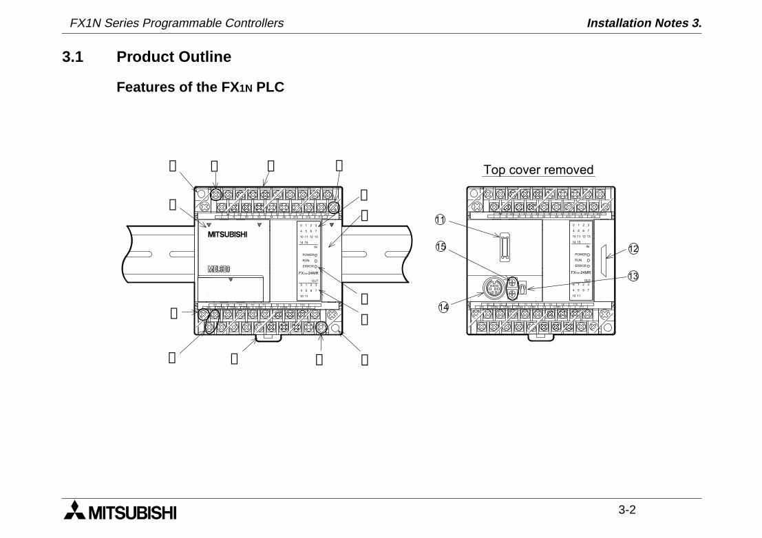
3.1 Product Outline
Features of the FX 1N PLC
➁ ➂
➀
➉ ➈
➇
➄
➆
Top cover removed
➁
X0 X2X1 X3 X5
X4X7
X6X11
X10S/S X13
X12X15
X14L N
0V24V Y7 Y11
Y10Y5Y4
Y0 Y2Y1COM0
Y3
POWER
ERROR
IN
OUT
0 1 2 3
0 1 2 3
RUN
4 5 6 7
4 5 6 7
1110
131110 12
14 15
POWER
ERROR
IN
OUT0 1 2 3
0 1 2 3
RUN
4 5 6 7
4 5 6 7
1110
131110 12
14 15
Y6
FX1N-24MRFX1N-24MR
➂
➂
➂
➅
➃
COM1 COM2 COM3 COM4
X0 X2X1 X3 X5
X4X7
X6X11
X10S/S X13
X12X15
X14L N
0V24V Y7 Y11
Y10Y5Y4
Y0 Y2Y1COM0
Y3 Y6COM1 COM2 COM3 COM4
11
15
14
12
13
FX1N Series Programmable Controllers Installation Notes 3.
3-3
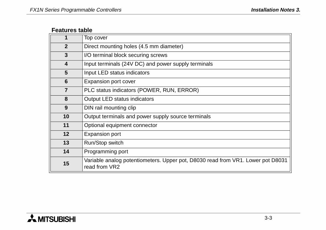
Features table1 Top cover
2 Direct mounting holes (4.5 mm diameter)
3 I/O terminal block securing screws
4 Input terminals (24V DC) and power supply terminals
5 Input LED status indicators
6 Expansion port cover
7 PLC status indicators (POWER, RUN, ERROR)
8 Output LED status indicators
9 DIN rail mounting clip
10 Output terminals and power supply source terminals
11 Optional equipment connector
12 Expansion port
13 Run/Stop switch
14 Programming port
15Variable analog potentiometers. Upper pot, D8030 read from VR1. Lower pot D8031 read from VR2
FX1N Series Programmable Controllers Installation Notes 3.
3-4
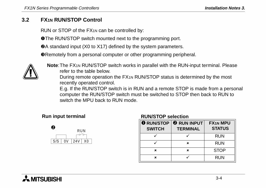
3.2 FX1N RUN/STOP Control
RUN or STOP of the FX1N can be controlled by:
The RUN/STOP switch mounted next to the programming port.
A standard input (X0 to X17) defined by the system parameters.
Remotely from a personal computer or other programming peripheral.
Note :The FX1N RUN/STOP switch works in parallel with the RUN-input terminal. Please refer to the table below.During remote operation the FX1N RUN/STOP status is determined by the most recently operated control.E.g. If the RUN/STOP switch is in RUN and a remote STOP is made from a personal computer the RUN/STOP switch must be switched to STOP then back to RUN to switch the MPU back to RUN mode.
S/S
RU N
0V 24V X0
RUN/STOP selection RUN/STOP
SWITCH RUN INPUT
TERMINALFX1N MPU STATUS
ü ü RUN
ü û RUN
û û STOP
û ü RUN
Run input terminal
FX1N Series Programmable Controllers Installation Notes 3.
3-5
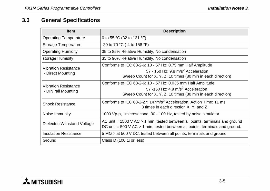
3.3 General Specifications
Item Description
Operating Temperature 0 to 55 °C (32 to 131 °F)
Storage Temperature -20 to 70 °C (-4 to 158 °F)
Operating Humidity 35 to 85% Relative Humidity, No condensation
storage Humidity 35 to 90% Relative Humidity, No condensation
Vibration Resistance - Direct Mounting
Conforms to IEC 68-2-6; 10 - 57 Hz: 0.75 mm Half Amplitude
57 - 150 Hz: 9.8 m/s2 Acceleration Sweep Count for X, Y, Z: 10 times (80 min in each direction)
Vibration Resistance - DIN rail Mounting
Conforms to IEC 68-2-6; 10 - 57 Hz: 0.035 mm Half Amplitude
57 -150 Hz: 4.9 m/s2 Acceleration Sweep Count for X, Y, Z: 10 times (80 min in each direction)
Shock Resistance Conforms to IEC 68-2-27: 147m/s2 Acceleration, Action Time: 11 ms 3 times in each direction X, Y, and Z
Noise Immunity 1000 Vp-p, 1microsecond, 30 - 100 Hz, tested by noise simulator
Dielectric Withstand Voltage AC unit = 1500 V AC > 1 min, tested between all points, terminals and groundDC unit = 500 V AC > 1 min, tested between all points, terminals and ground.
Insulation Resistance 5 MΩ > at 500 V DC, tested between all points, terminals and ground
Ground Class D (100 Ω or less)
FX1N Series Programmable Controllers Installation Notes 3.
3-6
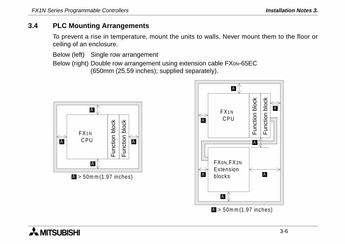
3.4 PLC Mounting Arrangements
To prevent a rise in temperature, mount the units to walls. Never mount them to the floor orceiling of an enclosure.
Below (left) Single row arrangement Below (right) Double row arrangement using extension cable FX0N-65EC
(650mm (25.59 inches); supplied separately).
FX 1N
C PU
Fun
ctio
n bl
ock
Fun
ctio
n bl
ock
A
A
A
FX 0N,FX 2N
ExtensionblocksA
A
A
> 50m m (1.97 inches)A
A
FX 1N
C PU
Fun
ctio
n bl
ock
Fun
ctio
n bl
ock
A
A
AA
> 50m m (1.97 inches)A
FX1N Series Programmable Controllers Installation Notes 3.
3-7
Caution
• Units should not be installed in areas subject to the following conditions: excessive or conductive dust, corrosive or flammable gas, moisture or rain, excessive heat, regular impact shocks or excessive vibration.
• Take special care not to allow debris to fall inside the unit during installation e.g. cut wires, shavings etc. Once installation is complete remove the protective paper band, to prevent overheating.
3.5 DIN Rail Mounting
Units can be snap mounted to 35mm DIN rail (DIN EN 50022). To release, pull the springloaded clips away from the rail and slide the unit up and off.
FX1N Series Programmable Controllers Installation Notes 3.
3-8
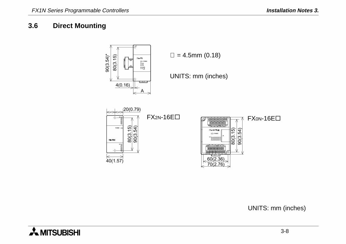
3.6 Direct Mounting
POWERS
P G 0O O GT D P
RR
F R C EP P L R
A
80
(3.1
5)
90(3
.54)*
4(0.16)
∅ = 4.5mm (0.18)
UNITS: mm (inches)
1IN 0
7
23456
POWER
1IN 0
7
23456
20(0.79)
80
(3.1
5)
90
(3.5
4)
40(1.57)
COM1 Y1 COM2 Y5 Y7Y0 Y2 Y4 Y6
Y0COM3
Y2 Y6Y3 COM4 Y7
POWER
7
7
0
OUT
1
1
2
2
3
3
4
4
5
5
6
60
Y3
Y1 Y5Y4 8
0(3
.15
)
90
(3.5
4)
70(2.76)60(2.36)
FX2N-16E¨ FX0N-16E¨
UNITS: mm (inches)

FX1N Series Programmable Controllers Installation Notes 3.
3-9
Side view
MODEL A MODEL A MODEL A
FX2N-4DA
55(2.16)
FX2N-2DA
43(1.69)
FX0N-32NT-DP
43(1.69)
FX2N-4AD FX2N-2AD FX0N-232ADP
FX2N-4AD-PT FX2N-32CCL FX0N-485ADP
FX2N-4AD-TC FX2N-16LNK-M FX0N-8E¨FX2N-16CCL-M 85(3.34) FX0N-3A FX0N-8E
87(3.42)*
9(0.35)
FX0N-232ADP is 68(2.68)
UNITS: mm (inches)
FX1N Series Programmable Controllers Installation Notes 3.
3-10
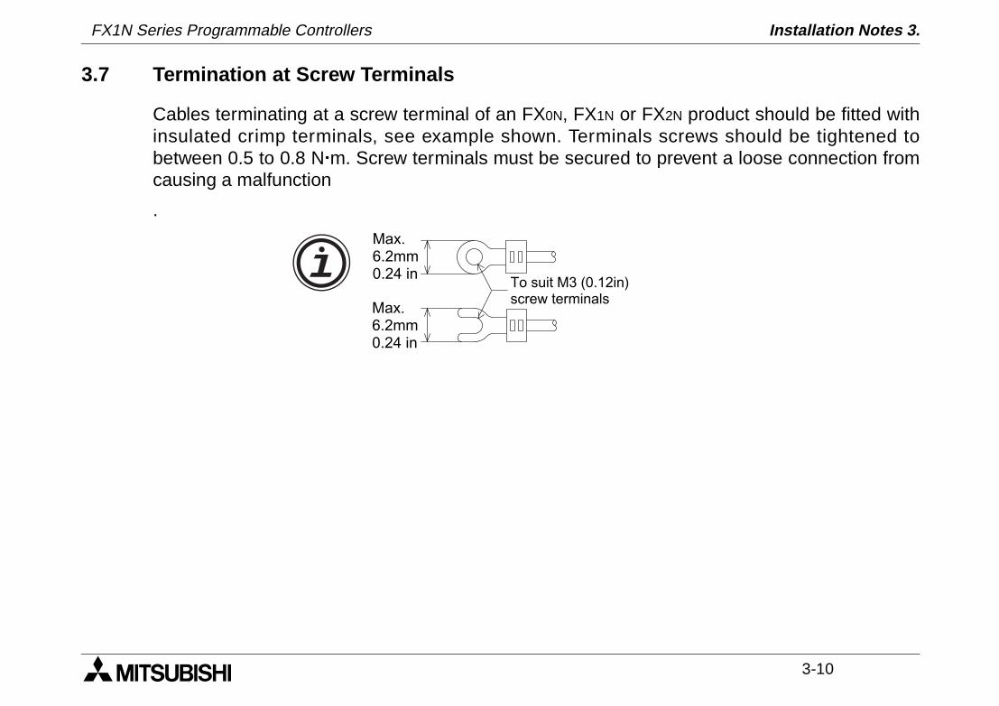
3.7 Termination at Screw Terminals
Cables terminating at a screw terminal of an FX0N, FX1N or FX2N product should be fitted withinsulated crimp terminals, see example shown. Terminals screws should be tightened tobetween 0.5 to 0.8 N m. Screw terminals must be secured to prevent a loose connection fromcausing a malfunction
.
To suit M3 (0.12in)screw terminals
Max.6.2mm0.24 in
Max.6.2mm0.24 in
FX1N Series Programmable Controllers Installation Notes 3.
3-11
3.8 Wiring Techniques
The wiring of FX1N products has been designed to be safe and easy. If during the installation ofthese products or associated products concern is felt, please contact a professional electricianwho is trained to the local and national standards applicable to the installation site.
Wiring cautions
• Do not run input signals in the same multicore cable as output signals or allow them to share the same wire.
• Do not lay I/O signal cables next to power cables or allow them to share the same trunking duct. Low voltage cables should be reliably separated or insulated with regard to high voltage cabling.
• Where I/O signal lines are used over an extended distance consideration for voltage drop and noise interference should be made.
• Always ensure that mounted units and blocks are kept as far as possible from high-voltage cables, high-voltage equipment and power equipment.
FX1N Series Programmable Controllers Installation Notes 3.
3-12
3.9 Installing Optional Units
3.9.1 Special Function Boards
The following is a generic explanation of how to install a special function board to the FX1N
PLC. For greater detail, specifications and wiring examples for each optional unit, please seethe relevant product manuals.
Always make sure the power is turned off, before installing a special function board. Only oneboard can be used at any one time, do not try to stack multiple boards.
MODEL USE WITH FX1N-5DM USE WITH FX1N-EEPROM-8L
FX1N-232-BD ü
Possible for program upload anddownload while the PLC is in theSTOP mode.
FX1N-422-BD ü
FX1N-485-BD ü
FX1N-CNV-BD ü
FX1N-8AV-BD ü
FX1N-4EX-BD ü
FX1N-2EYT-BD ü
FX1N-2AD-BD û û
FX1N-1DA-BD û û
FX1N Series Programmable Controllers Installation Notes 3.
3-13
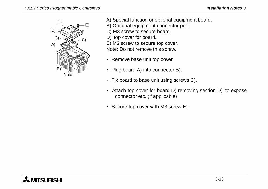
A) Special function or optional equipment board. B) Optional equipment connector port. C) M3 screw to secure board. D) Top cover for board. E) M3 screw to secure top cover. Note: Do not remove this screw.
• Remove base unit top cover.
• Plug board A) into connector B).
• Fix board to base unit using screws C).
• Attach top cover for board D) removing section D)’ to exposeconnector etc. (if applicable)
• Secure top cover with M3 screw E).
A)
B)
C)
D)
D)'E)
Note
C)
FX1N Series Programmable Controllers Installation Notes 3.
3-14
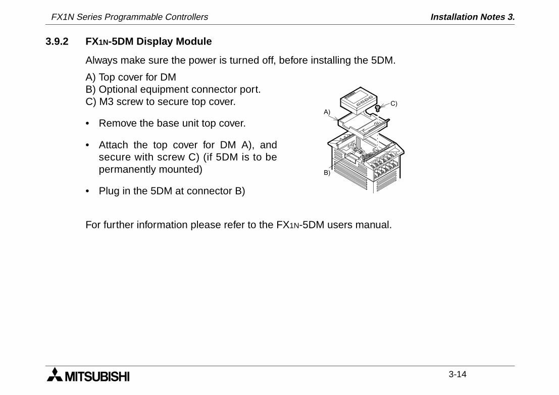
3.9.2 FX1N-5DM Display Module
Always make sure the power is turned off, before installing the 5DM.
A) Top cover for DMB) Optional equipment connector port.C) M3 screw to secure top cover.
• Remove the base unit top cover.
• Attach the top cover for DM A), andsecure with screw C) (if 5DM is to bepermanently mounted)
• Plug in the 5DM at connector B)
For further information please refer to the FX1N-5DM users manual.
B)
A)C)
1 INTRODUCTION
2 TERMINAL LAYOUTS
3 INSTALLATION NOTES
4 POWER SUPPLY
5 INPUTS
6 OUTPUTS
7 DIAGNOSTICS
FX1N Series Programmable Controllers Power supply 4.

FX1N Series Programmable Controllers Power supply 4.
Power Supply 4.
4-1
4. Power Supply
4.1 Wiring Techniques
The wiring of FX1N products has been designed to be safe and easy. If during the installation ofthese product or associated products concern is felt, please contact a professional electricianwho is trained to the local and national standards applicable to the installation site.
4.2 Wiring Cautions
• Do not run input signals in the same multicore cable as output signals or allow them to share thesame wire.
• Do not lay I/O signal cables next to power cables or allow them to share the same trunking duct. Lowvoltage cables should be reliably separated or insulated with regard to high voltage cabling.
• Where I/O signal lines are used over an extended distance consideration for voltage drop and noiseinterference should be made.
4.3 Power Supply
When wiring AC supplies the “Live” cable should be connected to the “L” terminal and the “Neutral” cableshould be connected to the “N” terminal. Do NOT connect the “Live” wire to the “N” terminal, the user mightreceive a dangerous shock on powerup.
When wiring DC supplies the “Live” cable should be connected to the “+” terminal and the “Neutral” cableshould be connected to the “-” terminal. Do NOT connect the “Live” wire to the “-” terminal, the user mightreceive a dangerous shock on powerup.
FX1N Series Programmable Controllers
FX1N Series Programmable Controllers Power Supply 4.
4-2
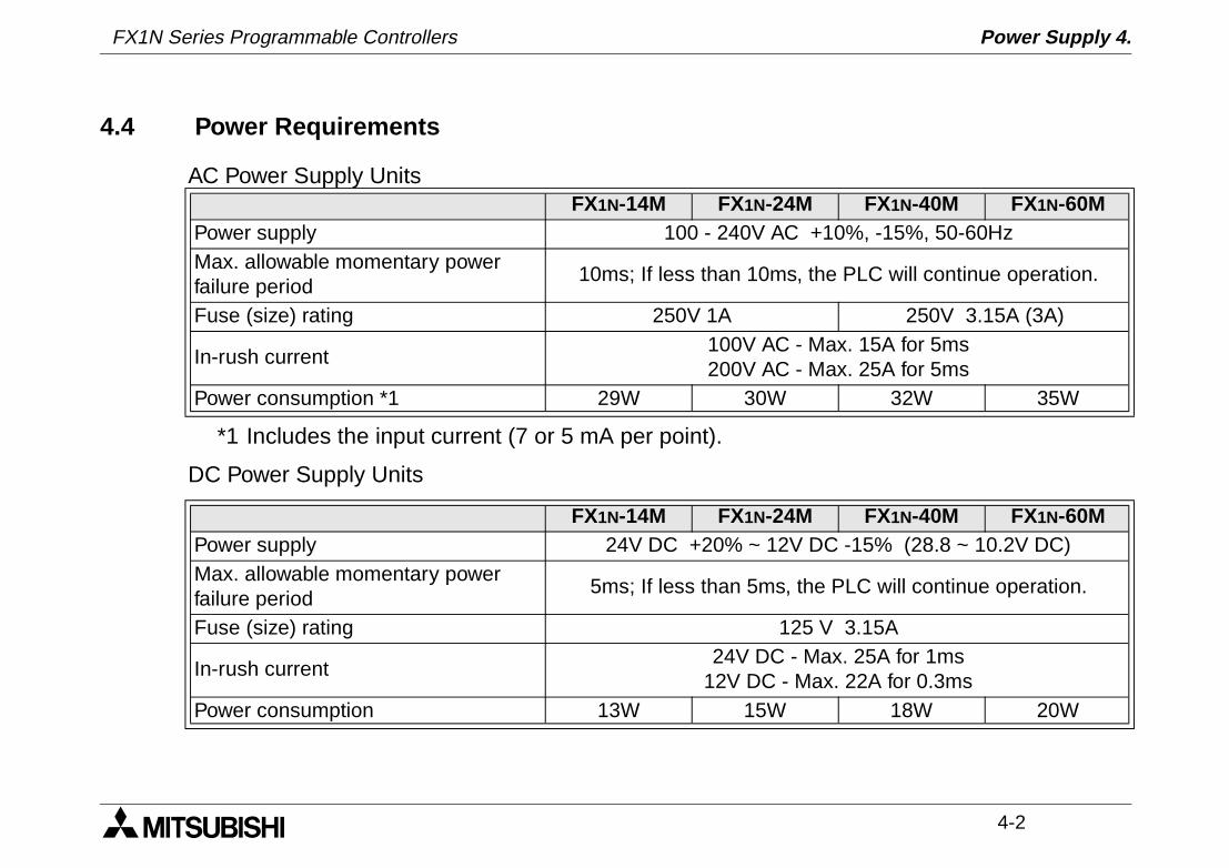
*1 Includes the input current (7 or 5 mA per point).
DC Power Supply Units
4.4 Power Requirements
AC Power Supply UnitsFX1N-14M FX1N-24M FX1N-40M FX1N-60M
Power supply 100 - 240V AC +10%, -15%, 50-60HzMax. allowable momentary power failure period
10ms; If less than 10ms, the PLC will continue operation.
Fuse (size) rating 250V 1A 250V 3.15A (3A)
In-rush current100V AC - Max. 15A for 5ms200V AC - Max. 25A for 5ms
Power consumption *1 29W 30W 32W 35W
FX1N-14M FX1N-24M FX1N-40M FX1N-60MPower supply 24V DC +20% ~ 12V DC -15% (28.8 ~ 10.2V DC)Max. allowable momentary power failure period
5ms; If less than 5ms, the PLC will continue operation.
Fuse (size) rating 125 V 3.15A
In-rush current24V DC - Max. 25A for 1ms
12V DC - Max. 22A for 0.3msPower consumption 13W 15W 18W 20W
FX1N Series Programmable Controllers Power Supply 4.
4-3
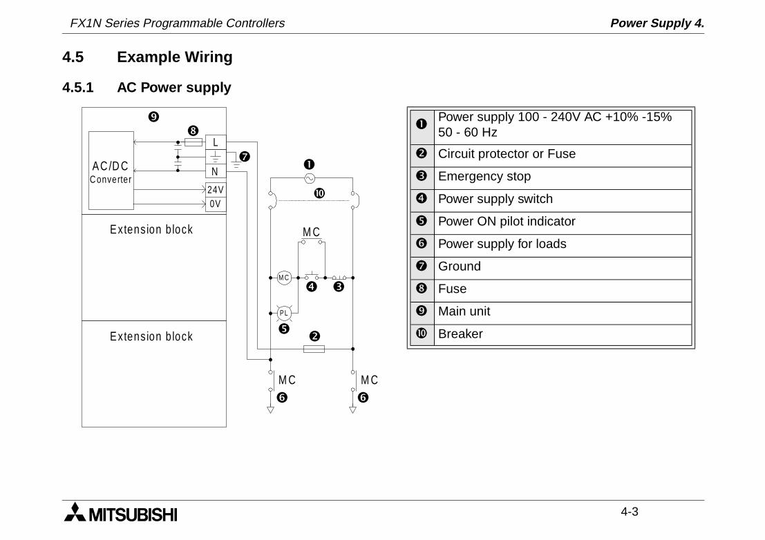
4.5 Example Wiring
4.5.1 AC Power supply
AC /D CC onverter
Extens ion b lock
Extens ion b lock
M C
PL
M C
M C M C
L
N
24V0V
Power supply 100 - 240V AC +10% -15%50 - 60 Hz
Circuit protector or Fuse
Emergency stop
Power supply switch
Power ON pilot indicator
Power supply for loads
Ground
Fuse
Main unit
Breaker
FX1N Series Programmable Controllers Power Supply 4.
4-4
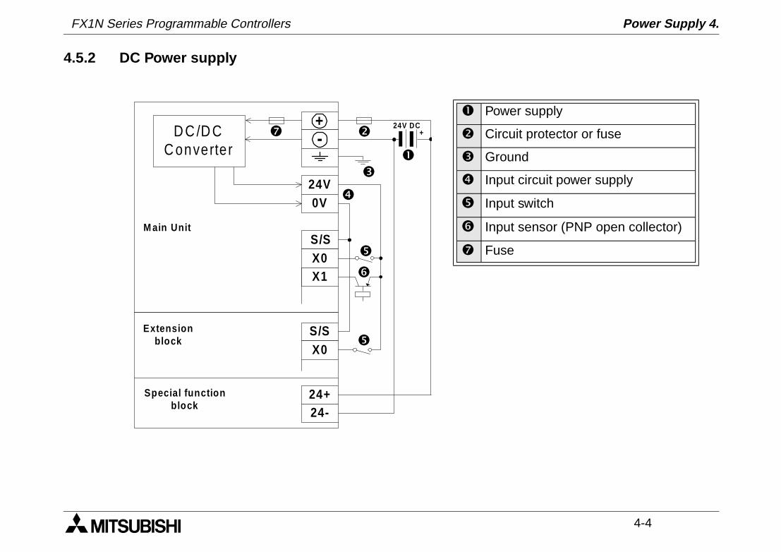
4.5.2 DC Power supply
Power supply
Circuit protector or fuse
Ground
Input circuit power supply
Input switch
Input sensor (PNP open collector)
Fuse
D C /D CC onverter
+-
24V0V
S/SX0X1
S/SX0
24+24-
24V DC
M ain Unit
Extensionblock
Special functionblock
+

FX1N Series Programmable Controllers Power Supply 4.
4-5
Power supply
Circuit protector or fuse
Ground
Input circuit power supply
Input switch
Input sensor (PNP open collector)
Fuse
D C /D CC onverter
+-
24V0V
S/SX0X1
S/SX0
12V DC
M ain Unit
Extensionblock
+
FX1N Series Programmable Controllers Power Supply 4.
4-6
4.6 Service Power supply
An AC powered FX1N can supply a service current of 24V DC at 400mA when used on its ownand, when used with extension or special function blocks.
A DC powered FX1N does not have the capacity to supply a service current. HoweverAdditional extension blocks can be powered from the main unit power supply
4.7 Earthing / Grounding
Use a cable at least 0.2mm2 (AWG24) to ground equipment. Ground resistance must be less than 100Ω (class D). Note that the ground cable must not be connected to the same ground as the power circuits. Grounding is recommended but if a proper ground cannot be provided, the PLC will still operate correctly without being grounded.
1 INTRODUCTION
2 TERMINAL LAYOUTS
3 INSTALLATION NOTES
4 POWER SUPPLY
5 INPUTS
6 OUTPUTS
7 DIAGNOSTICS
FX1N Series Programmable Controllers Inputs 5.
FX1N Series Programmable Controllers Inputs 5.

Inputs 5.
5-1
5. Inputs
5.1 24V DC input Specifications
FX1N main unit,extension block FX0N, FX2N Extension block
X0 àààà X7 X10 àààà ∞Input voltage 24V DC ±10%
Input current 24V DC, 7mA 24V DC, 5mA 24V DC, 5mA
Input switching current
OFF à ON >4.5mA >3.5mA >3.5mA
ON à OFF <1.5mA
Response time 10ms
Variable response time X000-X007 0-15ms ---
Circuit isolation Photocoupler
Operation indication LED is lit
FX1N Series Programmable Controllers
FX1N Series Programmable Controllers Inputs 5.
5-2
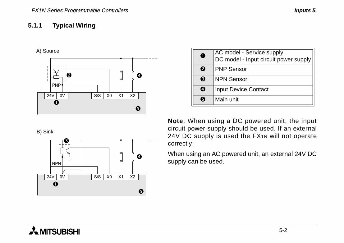
5.1.1 Typical Wiring
Note : When using a DC powered unit, the inputcircuit power supply should be used. If an external24V DC supply is used the FX1N will not operatecorrectly.
When using an AC powered unit, an external 24V DCsupply can be used.
AC model - Service supplyDC model - Input circuit power supply
PNP Sensor
NPN Sensor
Input Device Contact
Main unit24V 0V S/S X0 X1 X2
PNP
24V 0V S/S X0 X1 X2
NPN
A) Source
B) Sink
FX1N Series Programmable Controllers Inputs 5.
5-3
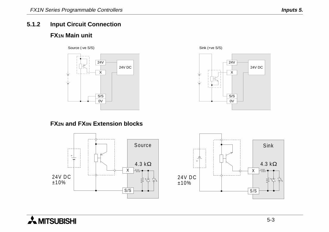
5.1.2 Input Circuit Connection
FX1N Main unit
FX2N and FX0N Extension blocks
24V
X24V DC
0VS/S
Source (-ve S/S)
24V
X24V DC
0VS/S
Sink (+ve S/S)
S /S
X
Source
24V D C±10%
4.3 kΩ
S /S
X
S ink
24V D C±10%
4.3 kΩ
FX1N Series Programmable Controllers Inputs 5.
5-4
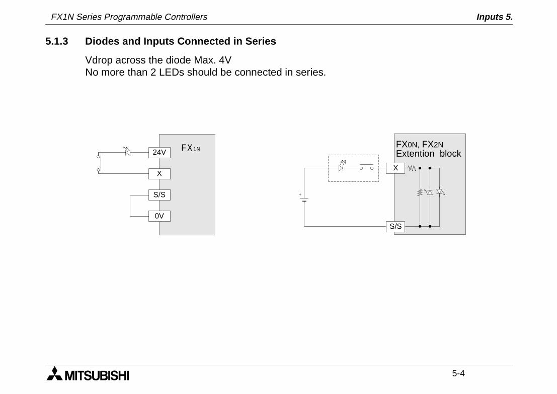
5.1.3 Diodes and Inputs Connected in Series
Vdrop across the diode Max. 4VNo more than 2 LEDs should be connected in series.
FX0N, FX2NExtention block
X
S/S
24V
X
0V
S/S
FX 1N
FX1N Series Programmable Controllers Inputs 5.
5-5
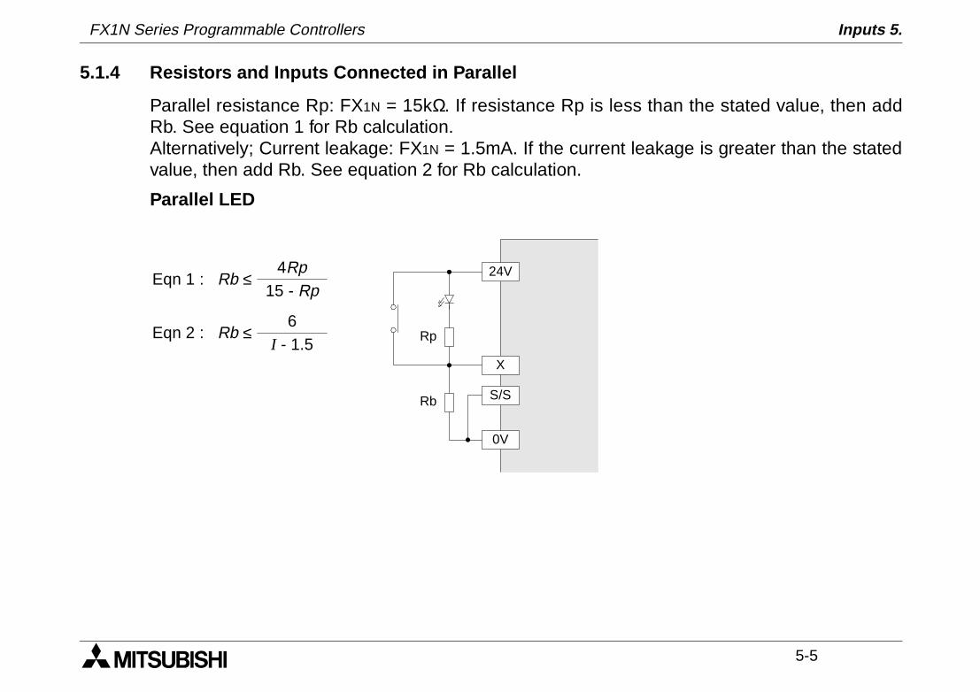
5.1.4 Resistors and Inputs Connected in Parallel
Parallel resistance Rp: FX1N = 15kΩ. If resistance Rp is less than the stated value, then addRb. See equation 1 for Rb calculation.Alternatively; Current leakage: FX1N = 1.5mA. If the current leakage is greater than the statedvalue, then add Rb. See equation 2 for Rb calculation.
Parallel LED
Rb ≤4Rp
15 - RpEqn 1 :
Rb ≤6
I - 1.5Eqn 2 :
24V
X
0V
S/S
Rp
Rb
FX1N Series Programmable Controllers Inputs 5.
5-6
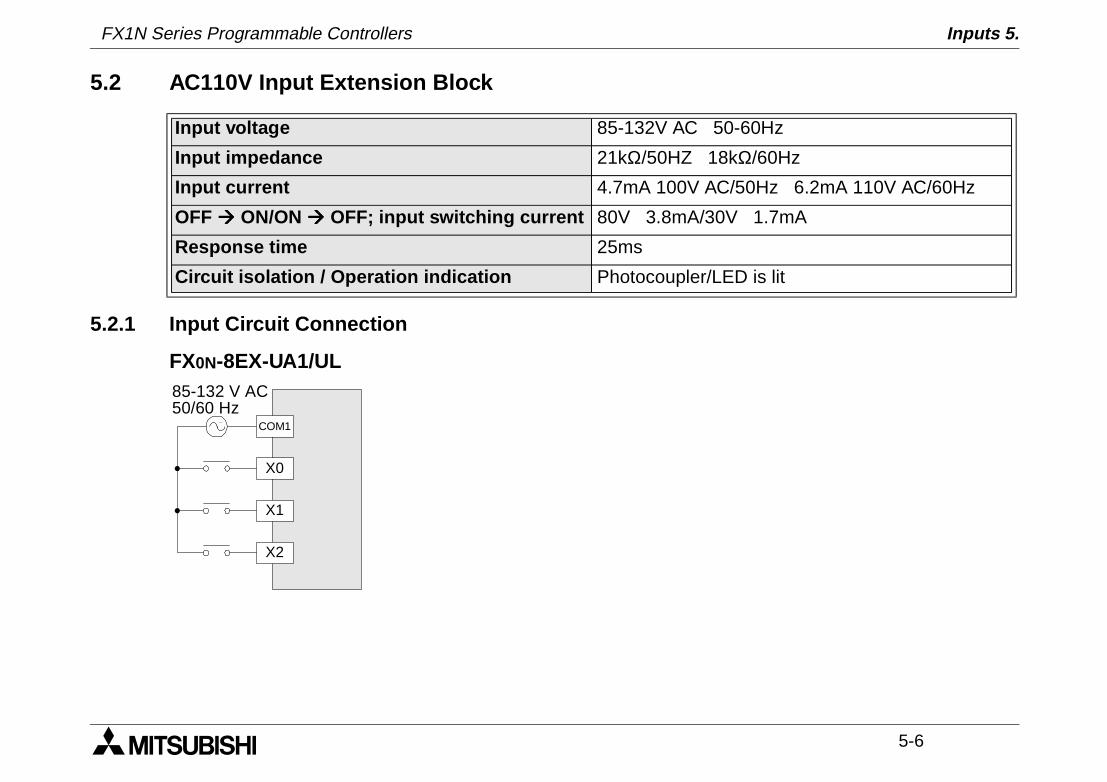
5.2 AC110V Input Extension Block
5.2.1 Input Circuit Connection
FX0N-8EX-UA1/UL
Input voltage 85-132V AC 50-60Hz
Input impedance 21kΩ/50HZ 18kΩ/60Hz
Input current 4.7mA 100V AC/50Hz 6.2mA 110V AC/60Hz
OFF àààà ON/ON àààà OFF; input switching current 80V 3.8mA/30V 1.7mA
Response time 25ms
Circuit isolation / Operation indication Photocoupler/LED is lit
X0
COM1
85-132 V AC50/60 Hz
X1
X2
FX1N Series Programmable Controllers Inputs 5.
5-7
5.2.2 Programming Caution
When using 110V AC units, high speed counter and interrupt routines are not suitable for usedue to the long 'ON/OFF' times. The following instructions are also not suitable.
FNC 52 MTR
FNC 56 SPD
FNC 72 DSW
FX1N Series Programmable Controllers Inputs 5.
5-8
MEMO
1 INTRODUCTION
2 TERMINAL LAYOUTS
3 INSTALLATION NOTES
4 POWER SUPPLY
5 INPUTS
6 OUTPUTS
7 DIAGNOSTICS
FX1N Series Programmable Controllers Outputs 6.

FX1N Series Programmable Controllers Outputs 6.
Outputs 6.
6-1
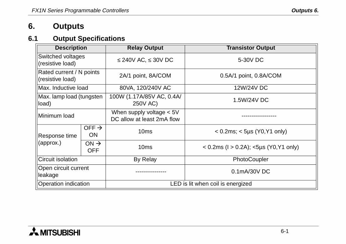
6. Outputs6.1 Output Specifications
Description Relay Output Transistor Output
Switched voltages (resistive load)
≤ 240V AC, ≤ 30V DC 5-30V DC
Rated current / N points (resistive load)
2A/1 point, 8A/COM 0.5A/1 point, 0.8A/COM
Max. Inductive load 80VA, 120/240V AC 12W/24V DC
Max. lamp load (tungsten load)
100W (1.17A/85V AC, 0.4A/250V AC)
1.5W/24V DC
Minimum loadWhen supply voltage < 5V DC allow at least 2mA flow
------------------
Response time (approx.)
OFF à ON
10ms < 0.2ms; < 5µs (Y0,Y1 only)
ON à OFF
10ms < 0.2ms (I > 0.2A); <5µs (Y0,Y1 only)
Circuit isolation By Relay PhotoCoupler
Open circuit current leakage
---------------- 0.1mA/30V DC
Operation indication LED is lit when coil is energized
FX1N Series Programmable Controllers
FX1N Series Programmable Controllers Outputs 6.
6-2
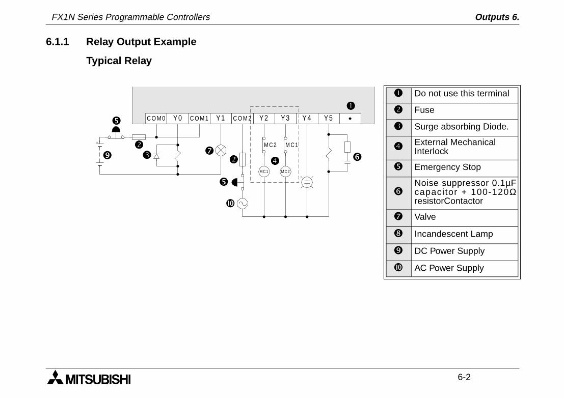
6.1.1 Relay Output Example
Typical Relay
Do not use this terminal
Fuse
Surge absorbing Diode.
External Mechanical Interlock
Emergency Stop
Noise suppressor 0.1µFcapacitor + 100-120ΩresistorContactor
Valve
Incandescent Lamp
DC Power Supply
AC Power Supply
C O M 0 Y 0 Y 1 Y 2 Y 3C O M 1 C O M 2 Y 4 Y 5
MC1 MC2
M C 2 M C 1+
FX1N Series Programmable Controllers Outputs 6.
6-3
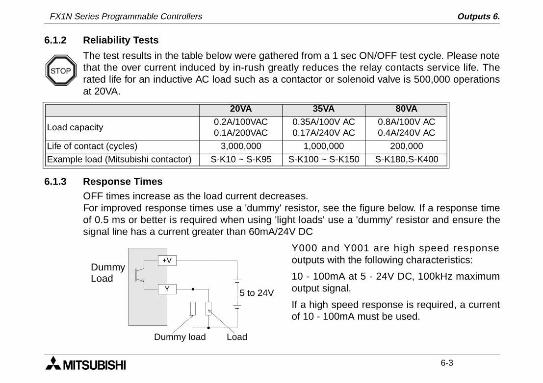
6.1.2 Reliability Tests
The test results in the table below were gathered from a 1 sec ON/OFF test cycle. Please notethat the over current induced by in-rush greatly reduces the relay contacts service life. Therated life for an inductive AC load such as a contactor or solenoid valve is 500,000 operationsat 20VA.
6.1.3 Response TimesOFF times increase as the load current decreases.For improved response times use a 'dummy' resistor, see the figure below. If a response timeof 0.5 ms or better is required when using 'light loads' use a 'dummy' resistor and ensure thesignal line has a current greater than 60mA/24V DC
Y000 and Y001 are high speed responseoutputs with the following characteristics:
10 - 100mA at 5 - 24V DC, 100kHz maximumoutput signal.
If a high speed response is required, a currentof 10 - 100mA must be used.
20VA 35VA 80VA
Load capacity0.2A/100VAC0.1A/200VAC
0.35A/100V AC0.17A/240V AC
0.8A/100V AC0.4A/240V AC
Life of contact (cycles) 3,000,000 1,000,000 200,000
Example load (Mitsubishi contactor) S-K10 ~ S-K95 S-K100 ~ S-K150 S-K180,S-K400
5 to 24VY
+V
Dummy load Load
10 to 100mA
DummyLoad
FX1N Series Programmable Controllers Outputs 6.
6-4
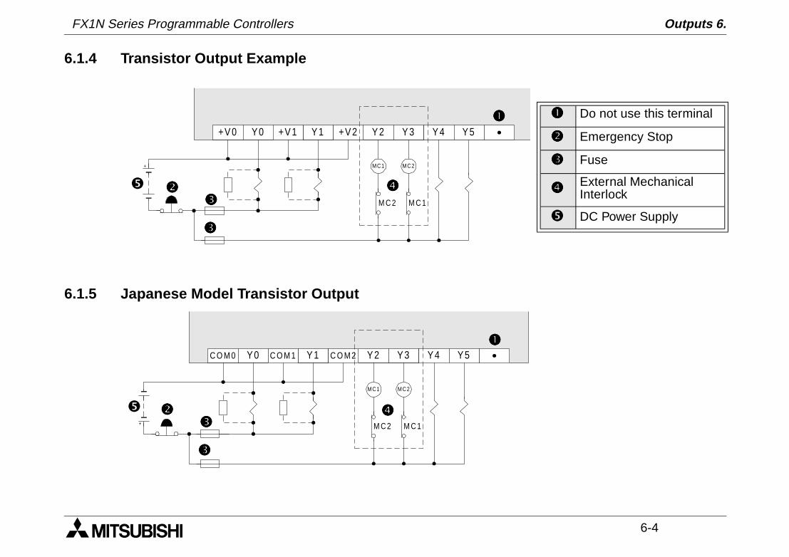
6.1.4 Transistor Output Example
6.1.5 Japanese Model Transistor Output
Do not use this terminal
Emergency Stop
Fuse
External Mechanical Interlock
DC Power Supply
+V 0 Y 0 Y 1 Y 2 Y 3+V 1 +V 2 Y 4 Y 5
MC1 MC2
M C 2 M C 1
+
C O M 0 Y 0 Y 1 Y 2 Y 3C O M 1 C O M 2 Y 4 Y 5
MC1 MC2
M C 2 M C 1+
FX1N Series Programmable Controllers Outputs 6.
6-5
6.2 Applying Safe Loads
Ensure all loads are applied to the same side of each PLC output, see previous figures. Loads which should NEVER simultaneously operate (e.g. direction control of a motor), because of a safety critical situation, should not rely on the PLC's sequencing alone. Mechanical interlocks MUST be fitted to all safety critical circuits. (See preceding figure.)

FX1N Series Programmable Controllers Outputs 6.
6-6
MEMO
1 INTRODUCTION
2 TERMINAL LAYOUTS
3 INSTALLATION NOTES
4 POWER SUPPLY
5 INPUTS
6 OUTPUTS
7 DIAGNOSTICS
FX1N Series Programmable Controllers Diagnostics 7.

FX1N Series Programmable Controllers Diagnostics 7.
Diagnostics 7.
7-1
7. Diagnostics
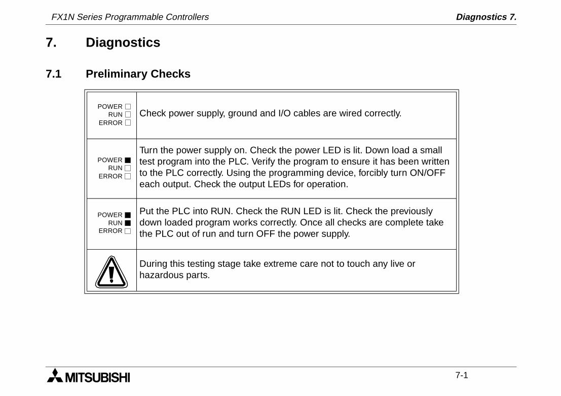
7.1 Preliminary Checks
Check power supply, ground and I/O cables are wired correctly.
Turn the power supply on. Check the power LED is lit. Down load a small test program into the PLC. Verify the program to ensure it has been written to the PLC correctly. Using the programming device, forcibly turn ON/OFF each output. Check the output LEDs for operation.
Put the PLC into RUN. Check the RUN LED is lit. Check the previously down loaded program works correctly. Once all checks are complete take the PLC out of run and turn OFF the power supply.
During this testing stage take extreme care not to touch any live or hazardous parts.
POWERRUN
ERROR
POWERRUN
ERROR
POWERRUN
ERROR
FX1N Series Programmable Controllers
FX1N Series Programmable Controllers Diagnostics 7.
7-2
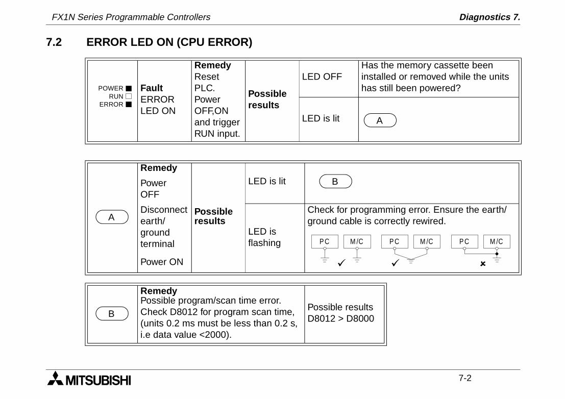
7.2 ERROR LED ON (CPU ERROR)
FaultERROR LED ON
RemedyReset PLC. Power OFF,ON and trigger RUN input.
Possible results
LED OFFHas the memory cassette been installed or removed while the units has still been powered?
LED is lit
Remedy
Possible results
LED is litPower OFF
Disconnect earth/ground terminal
LED is flashing
Check for programming error. Ensure the earth/ground cable is correctly rewired.
Power ON
RemedyPossible program/scan time error. Check D8012 for program scan time, (units 0.2 ms must be less than 0.2 s, i.e data value <2000).
Possible resultsD8012 > D8000
POWERRUN
ERROR
A
A
B
P C M /C P C M /C P C M /C
ü ü û
B
FX1N Series Programmable Controllers Diagnostics 7.
7-3
7.3 Common Errors
- Corroded contact points at some point in an I/O line.
- An I/O device has been used outside its specified operating range.
- An input signal occurs in a shorter time period that taken by one program scan.
7.4 Maintenance
- Check interior temperature of the panel.
- Check panel air filters if fitted.
- Check for loosening of terminals or mounting facilities (due to vibration).
FX1N Series Programmable Controllers Diagnostics 7.
7-4
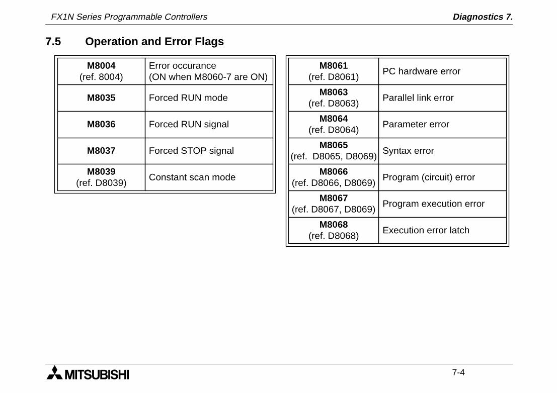
7.5 Operation and Error Flags
Parallel link error
Parameter error
Syntax error
Program (circuit) error
Program execution error
Execution error latch
M8063(ref. D8063)
M8064(ref. D8064)
M8065(ref. D8065, D8069)
M8066(ref. D8066, D8069)
M8067(ref. D8067, D8069)
M8068(ref. D8068)
PC hardware errorM8061
(ref. D8061)M8004
(ref. 8004)
M8035
M8036
M8037
M8039(ref. D8039)
Error occurance(ON when M8060-7 are ON)
Forced RUN mode
Forced RUN signal
Forced STOP signal
Constant scan mode
FX1N Series Programmable Controllers Diagnostics 7.
7-5
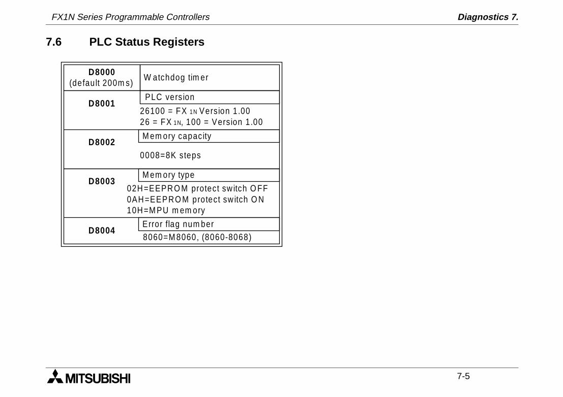
7.6 PLC Status Registers
02H =EEPR O M protect sw itch O FF0AH =EEPRO M protect sw itch O N10H =M PU m em ory
D8000(default 200m s)
D8001
D8002
D8003
D8004
W atchdog tim er
PLC vers ion
26100 = FX 1N Version 1.0026 = FX 1N, 100 = Version 1.00
M em ory capacity
0008=8K steps
M em ory type
Error flag num ber8060=M 8060, (8060-8068)
FX1N Series Programmable Controllers Diagnostics 7.
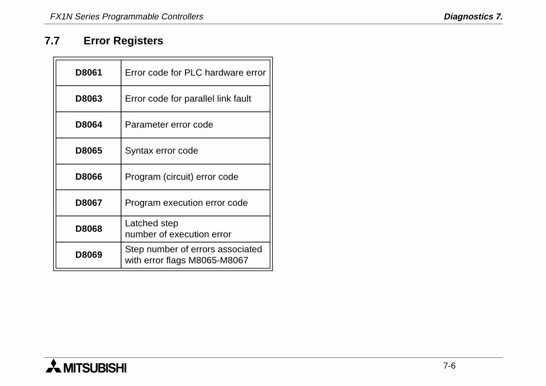
7-6
7.7 Error Registers
D8061
D8063
D8064
D8065
D8066
D8067
D8068
D8069
Error code for PLC hardware error
Error code for parallel link fault
Parameter error code
Syntax error code
Program (circuit) error code
Program execution error code
Latched stepnumber of execution error
Step number of errors associatedwith error flags M8065-M8067
FX1N Series Programmable Controllers Diagnostics 7.
7-7
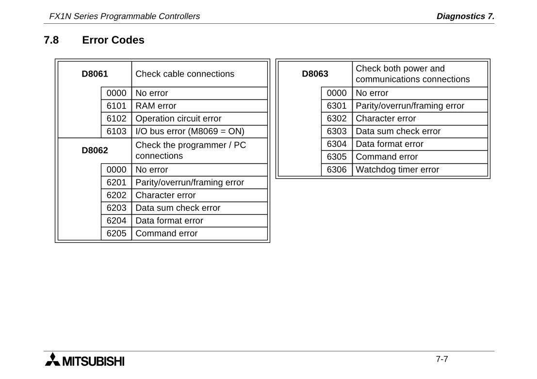
7.8 Error Codes
D8061 Check cable connections
No error0000RAM error6101Operation circuit error6102I/O bus error (M8069 = ON)6103
D8062 Check the programmer / PCconnections
No error0000Parity/overrun/framing error6201Character error6202Data sum check error6203Data format error6204Command error6205
D8063 Check both power andcommunications connections
No error0000Parity/overrun/framing error6301Character error6302Data sum check error6303Data format error6304Command error6305Watchdog timer error6306
FX1N Series Programmable Controllers Diagnostics 7.
7-8
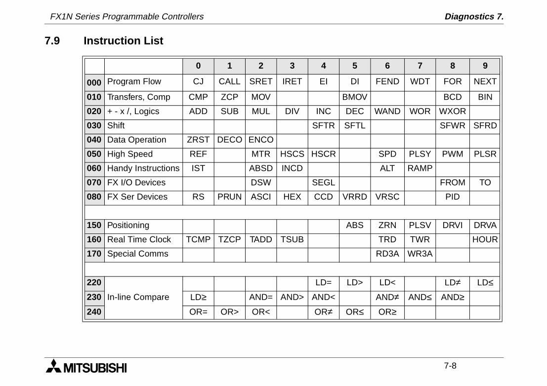
7.9 Instruction List
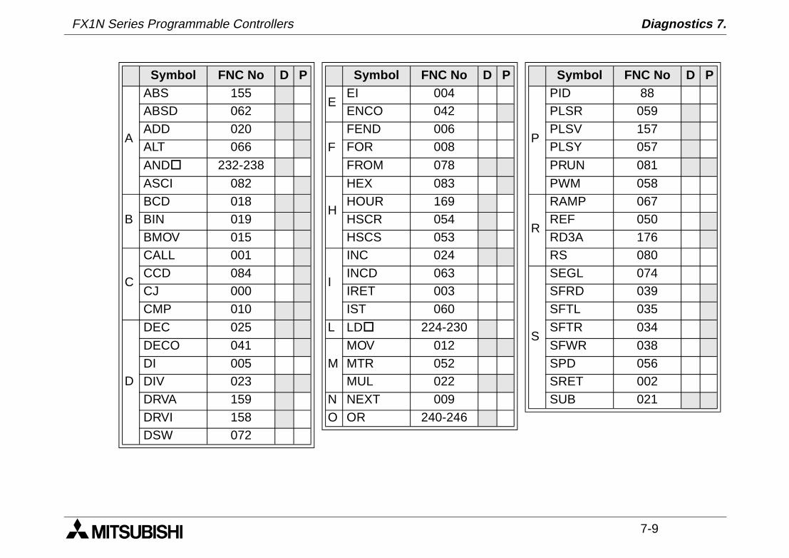
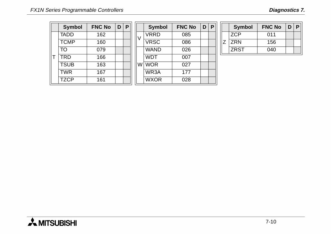
0 1 2 3 4 5 6 7 8 9
000 Program Flow CJ CALL SRET IRET EI DI FEND WDT FOR NEXT
010 Transfers, Comp CMP ZCP MOV BMOV BCD BIN
020 + - x /, Logics ADD SUB MUL DIV INC DEC WAND WOR WXOR
030 Shift SFTR SFTL SFWR SFRD
040 Data Operation ZRST DECO ENCO
050 High Speed REF MTR HSCS HSCR SPD PLSY PWM PLSR
060 Handy Instructions IST ABSD INCD ALT RAMP
070 FX I/O Devices DSW SEGL FROM TO
080 FX Ser Devices RS PRUN ASCI HEX CCD VRRD VRSC PID
150 Positioning ABS ZRN PLSV DRVI DRVA
160 Real Time Clock TCMP TZCP TADD TSUB TRD TWR HOUR
170 Special Comms RD3A WR3A
220
In-line Compare
LD= LD> LD< LD≠ LD≤230 LD≥ AND= AND> AND< AND≠ AND≤ AND≥240 OR= OR> OR< OR≠ OR≤ OR≥
FX1N Series Programmable Controllers Diagnostics 7.
7-9
Symbol FNC No D P Symbol FNC No D P Symbol FNC No D P
A
ABS 155E
EI 004
P
PID 88ABSD 062 ENCO 042 PLSR 059ADD 020
F
FEND 006 PLSV 157ALT 066 FOR 008 PLSY 057
ANDo 232-238 FROM 078 PRUN 081
ASCI 082
H
HEX 083 PWM 058
BBCD 018 HOUR 169
R
RAMP 067BIN 019 HSCR 054 REF 050BMOV 015 HSCS 053 RD3A 176
C
CALL 001
I
INC 024 RS 080CCD 084 INCD 063
S
SEGL 074CJ 000 IRET 003 SFRD 039CMP 010 IST 060 SFTL 035
D
DEC 025 L LDo 224-230 SFTR 034
DECO 041M
MOV 012 SFWR 038DI 005 MTR 052 SPD 056DIV 023 MUL 022 SRET 002DRVA 159 N NEXT 009 SUB 021DRVI 158 O OR 240-246DSW 072
FX1N Series Programmable Controllers Diagnostics 7.
7-10
T
TADD 162V
VRRD 085Z
ZCP 011TCMP 160 VRSC 086 ZRN 156TO 079
W
WAND 026 ZRST 040TRD 166 WDT 007TSUB 163 WOR 027TWR 167 WR3A 177TZCP 161 WXOR 028
Symbol FNC No D P Symbol FNC No D P Symbol FNC No D P
FX1N Series Programmable Controllers Diagnostics 7.
7-11
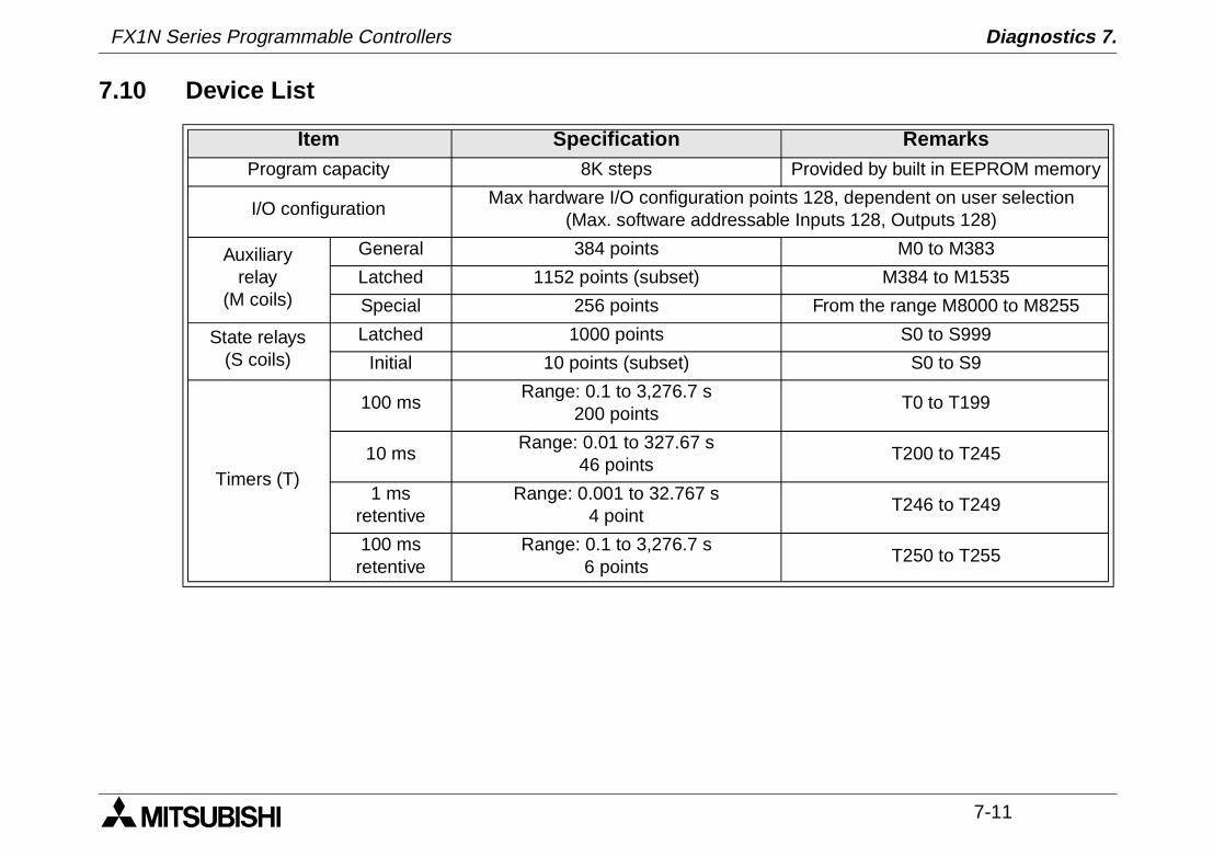
7.10 Device List
Item Specification RemarksProgram capacity 8K steps Provided by built in EEPROM memory
I/O configurationMax hardware I/O configuration points 128, dependent on user selection
(Max. software addressable Inputs 128, Outputs 128)
Auxiliaryrelay
(M coils)
General 384 points M0 to M383
Latched 1152 points (subset) M384 to M1535
Special 256 points From the range M8000 to M8255
State relays(S coils)
Latched 1000 points S0 to S999
Initial 10 points (subset) S0 to S9
Timers (T)
100 msRange: 0.1 to 3,276.7 s
200 points T0 to T199
10 msRange: 0.01 to 327.67 s
46 pointsT200 to T245
1 msretentive
Range: 0.001 to 32.767 s4 point
T246 to T249
100 msretentive
Range: 0.1 to 3,276.7 s6 points
T250 to T255
FX1N Series Programmable Controllers Diagnostics 7.
7-12
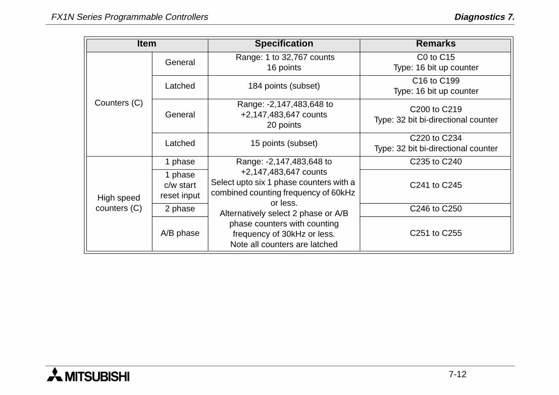
Counters (C)
General Range: 1 to 32,767 counts
16 pointsC0 to C15
Type: 16 bit up counter
Latched 184 points (subset)C16 to C199
Type: 16 bit up counter
General Range: -2,147,483,648 to
+2,147,483,647 counts20 points
C200 to C219Type: 32 bit bi-directional counter
Latched 15 points (subset)C220 to C234
Type: 32 bit bi-directional counter
High speedcounters (C)
1 phase Range: -2,147,483,648 to +2,147,483,647 counts
Select upto six 1 phase counters with a combined counting frequency of 60kHz
or less.Alternatively select 2 phase or A/B
phase counters with counting frequency of 30kHz or less.
Note all counters are latched
C235 to C240
1 phasec/w start
reset inputC241 to C245
2 phase C246 to C250
A/B phase C251 to C255
Item Specification Remarks
FX1N Series Programmable Controllers Diagnostics 7.
7-13
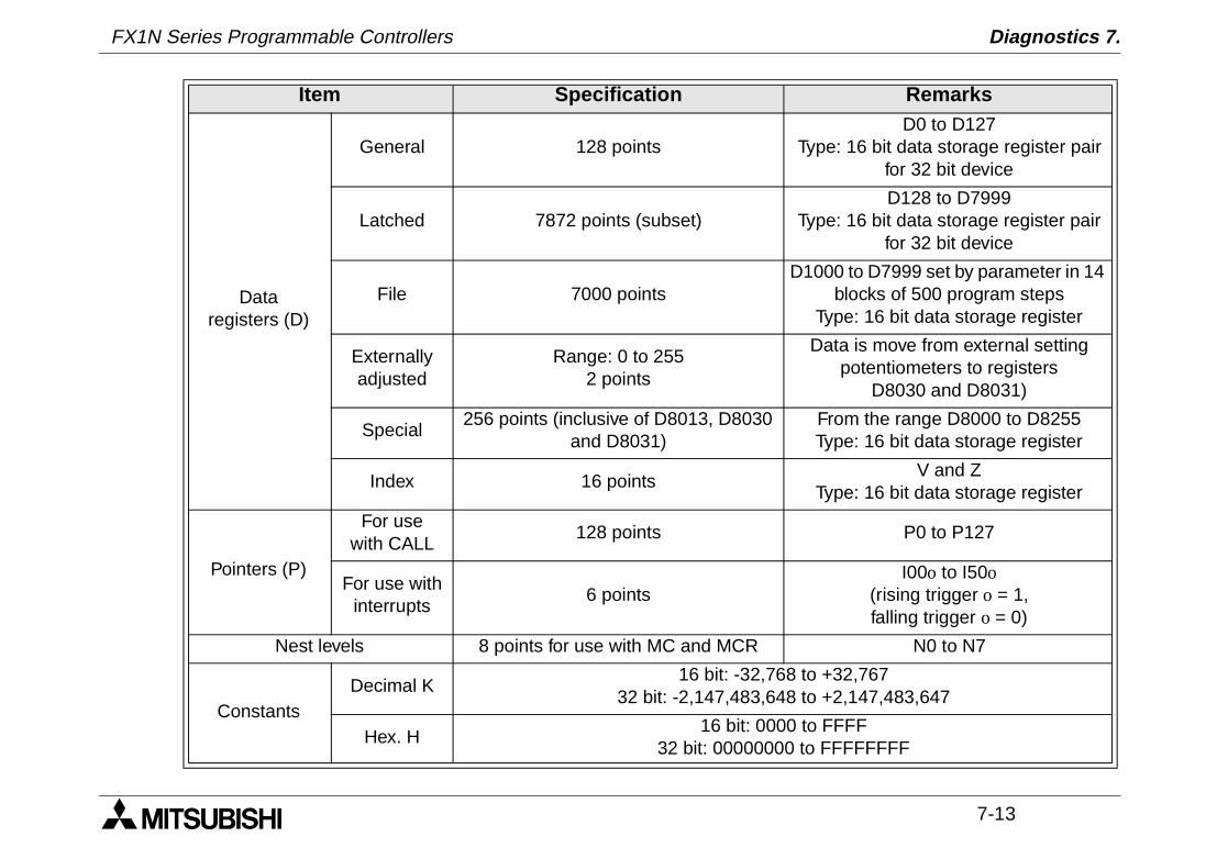
Dataregisters (D)
General 128 pointsD0 to D127
Type: 16 bit data storage register pair for 32 bit device
Latched 7872 points (subset)D128 to D7999
Type: 16 bit data storage register pair for 32 bit device
File 7000 pointsD1000 to D7999 set by parameter in 14
blocks of 500 program stepsType: 16 bit data storage register
Externallyadjusted
Range: 0 to 2552 points
Data is move from external setting potentiometers to registers
D8030 and D8031)
Special256 points (inclusive of D8013, D8030
and D8031)From the range D8000 to D8255Type: 16 bit data storage register
Index 16 pointsV and Z
Type: 16 bit data storage register
Pointers (P)
For usewith CALL
128 points P0 to P127
For use withinterrupts
6 pointsI00o to I50o
(rising trigger o = 1,falling trigger o = 0)
Nest levels 8 points for use with MC and MCR N0 to N7
ConstantsDecimal K
16 bit: -32,768 to +32,76732 bit: -2,147,483,648 to +2,147,483,647
Hex. H16 bit: 0000 to FFFF
32 bit: 00000000 to FFFFFFFF
Item Specification Remarks

FX1N Series Programmable Controllers Diagnostics 7.
7-14
MEMO

FX1N Series Programmable Controllers

HEAD OFFICE: MITSUBISHI DENKI BLDG MARUNOUCHI TOKYO 100-8310 TELEX: J24532 CABLE MELCO TOKYOHIMEJI WORKS: 840, CHIYODA CHO, HIMEJI, JAPAN
JY992D89301F(MEE)
Effective April. 2001Specification are subjectto change without notice.
HARDWARE MANUALFX1N SERIES PROGRAMMABLE CONTROLLERS