Embed Size (px)
Citation preview
© 2013 UTC Fire & Security. All rights reserved. 1 / 4 P/N 3101066 • REV 04 • REB 23JAN13
FX-PD Photoelectric Smoke Detector Installation Sheet
EN FR
EN: Installation Sheet
Operation The FX-PD Photoelectric Smoke Detector uses an optical sensing chamber to detect smoke. The detector analyzes the sensor data to determine whether to initiate an alarm. The detector is capable of performing comprehensive self-diagnostics and storing the results. The detector continuously monitors changes in sensitivity due to the environment (e.g., dirt, smoke, temperature, humidity) and notifies the loop controller of its condition. The detector issues a dirty-sensor warning when it reaches its preset limit. This notifies the operator of the need for service while the detector is still operating.
LED operation
The detector provides a bicolor LED that shows its status.
• Normal: Green LED flashes
• Alarm/active: Red LED flashes
Installation Refer to FireworX Smoke and Heat Detector Application Bulletin (P/N 3101107) for additional information on detector placement and spacing.
WARNINGS
• This detector does not operate without electrical power. As fires frequently cause power interruption, discuss further safeguards with the local fire protection specialist.
• This detector does not sense fires in areas where smoke cannot reach the detector. Smoke from fires in walls, roofs, or on the opposite side of closed doors may not reach the detector.
• Photoelectric detectors have a wide range of sensing capabilities but are best suited for detecting slow, smoldering fires.
• To ensure proper operation, schedule maintenance (regular or selected) in accordance with the requirements of the authority having jurisdiction. Refer to NFPA 72 and CAN/ULC-S536.
• To ensure proper operation, store the detector within the recommended ranges. Allow the detector to stabilize to room temperature before applying power.
• Keep the dust cover (supplied) on the detector during installation and remove it prior to commissioning and service. The dust cover is not a substitute for removing the detector during new construction or heavy remodeling.
To install the detector:
1. Install and wire the detector base using the installation sheet supplied with the detector base.
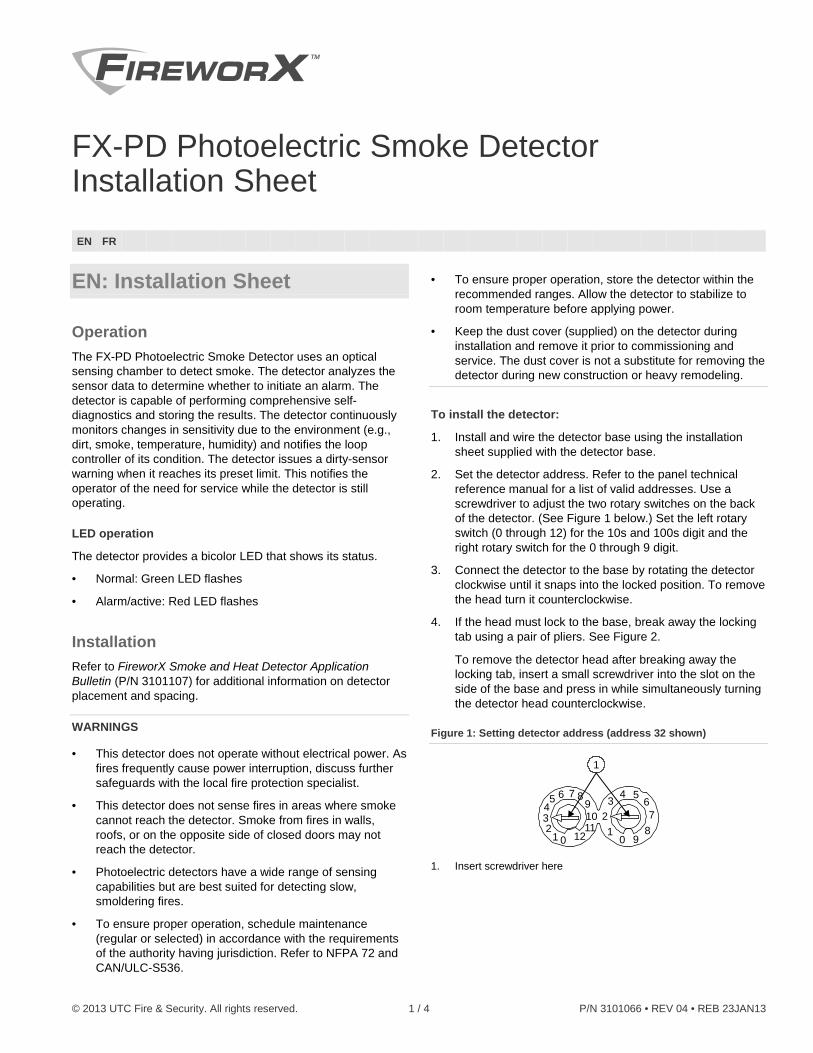
2. Set the detector address. Refer to the panel technical reference manual for a list of valid addresses. Use a screwdriver to adjust the two rotary switches on the back of the detector. (See Figure 1 below.) Set the left rotary switch (0 through 12) for the 10s and 100s digit and the right rotary switch for the 0 through 9 digit.
3. Connect the detector to the base by rotating the detector clockwise until it snaps into the locked position. To remove the head turn it counterclockwise.
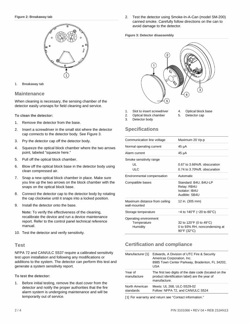
4. If the head must lock to the base, break away the locking tab using a pair of pliers. See Figure 2.
To remove the detector head after breaking away the locking tab, insert a small screwdriver into the slot on the side of the base and press in while simultaneously turning the detector head counterclockwise.
Figure 1: Setting detector address (address 32 shown)
012
345 6
1211109
87
0 91
23
4 567
8
1
1. Insert screwdriver here
2 / 4 P/N 3101066 • REV 04 • REB 23JAN13
Figure 2: Breakaway tab
1
012
34
5 6
1211109
87
0 91
23 4 5
67
8
1. Breakaway tab
Maintenance When cleaning is necessary, the sensing chamber of the detector easily unsnaps for field cleaning and service.
To clean the detector:
1. Remove the detector from the base.
2. Insert a screwdriver in the small slot where the detector cap connects to the detector body. See Figure 3.
3. Pry the detector cap off the detector body.
4. Squeeze the optical block chamber where the two arrows point, labeled “squeeze here.”
5. Pull off the optical block chamber.
6. Blow off the optical block base in the detector body using clean compressed air.
7. Snap a new optical block chamber in place. Make sure you line up the two arrows on the block chamber with the snaps on the optical block base.
8. Connect the detector cap to the detector body by rotating the cap clockwise until it snaps into a locked position.
9. Install the detector onto the base.
Note: To verify the effectiveness of the cleaning, recalibrate the device and run a device maintenance report. Refer to the control panel technical reference manual.
10. Test the detector and verify sensitivity.
Test NFPA 72 and CAN/ULC S537 require a calibrated sensitivity test upon installation and following any modifications or additions to the system. The detector can perform this test and generate a system sensitivity report.
To test the detector:
1. Before initial testing, remove the dust cover from the detector and notify the proper authorities that the fire alarm system is undergoing maintenance and will be temporarily out of service.
2. Test the detector using Smoke-In-A-Can (model SM-200) canned smoke. Carefully follow directions on the can to avoid damage to the detector.
Figure 3: Detector disassembly
1. Slot to insert screwdriver 2. Optical block chamber 3. Detector body
4. Optical block base 5. Detector cap
Specifications Communication line voltage Maximum 20 Vp-p
Normal operating current 45 µA
Alarm current 45 µA
Smoke sensitivity range UL ULC
0.67 to 3.66%/ft. obscuration 0.74 to 3.70%/ft. obscuration
Environmental compensation Automatic
Compatible bases Standard: B4U, B4U-LP Relay: RB4U Isolator: IB4U Audible: SB4U
Maximum distance from ceiling wall-mounted
12 in. (305 mm)
Storage temperature −4 to 140°F (−20 to 60°C)
Operating environment Temperature Humidity
32 to 120°F (0 to 49°C) 0 to 93% RH, noncondensing at 90°F (32°C)
Certification and compliance Manufacturer [1] Edwards, A Division of UTC Fire & Security
Americas Corporation, Inc. 8985 Town Center Parkway, Bradenton, FL 34202, USA
Year of manufacture
The first two digits of the date code (located on the product identification label) are the year of manufacture.
North American standards
Meets: UL 268, ULC-S529-02 Follow: NFPA 72, and CAN/ULC S524
[1] For warranty and return see “Contact information.”
P/N 3101066 • REV 04 • REB 23JAN13 3 / 4
Contact information For contact information, see www.edwardsutcfs.com.
FR: Fiche D'Installation
Fonctionnement Le détecteur de fumée photoélectrique, FX-PD utilise une chambre à détection optique pour localiser la fumée. Il analyse les données du capteur pour déterminer à quel moment déclencher l’alarme. Le détecteur surveille de façon continue tout changement de sensibilité causé par l’environnement (p. ex, saleté, fumée, température, humidité) et informe le contrôle de boucle de sa condition. Il émet un avertissement sensoriel de saleté lorsqu’il atteint sa limite préréglée. Cela informe l’opérateur d’un besoin de service pendant que le détecteur continue de fonctionner. Le détecteur peut effectuer des autodiagnostics complets et consigner les résultats.
Fonctionnement à électrode luminescente (DEL)
Le détecteur comporte un voyant DEL bicolore qui indique son statut.
• Normal : le voyant DEL vert clignote
• Alarme activée : le voyant DEL rouge clignote
Installation Consultez FireworX Smoke and Heat Detector Application Bulletin (P/N 3101107) pour plus de renseignements relativement à la pose et l’espacement des détecteurs.
MISES EN GARDE
• Ce détecteur ne fonctionne pas sans courant électrique. Les incendies étant souvent la cause d’interruption de courant, vous devriez discuter également des autres mesures de protection à prendre avec votre spécialiste de sécurité incendie local.
• Le détecteur ne localisera pas d’incendies dans les endroits où la fumée ne peut l’atteindre. Il se peut que la fumée provenant de foyers d’incendie dans les murs, sur les toits ou du côté opposé de portes fermées ne puisse pas atteindre le détecteur.
• Les détecteurs photoélectriques ont une grande capacité de détection, mais ils détectent mieux les feux lents et couvants.
• L’entretien (régulier ou déterminé) devrait être planifié conformément aux exigences de l’autorité ayant la compétence pour en assurer un bon fonctionnement. Consultez l’article 72 de la NFPA (É.-U.) et S536 des Laboratoires des assureurs du Canada (ULC).
• Pour un bon fonctionnement, installez le détecteur en deçà des limites recommandées. Laissez le détecteur se stabiliser à la température de la pièce avant de l’alimenter.
• Le pare-poussière (inclus) doit demeurer en place pendant l’installation, puis retiré avant d’activer le détecteur. On ne doit pas l’utiliser pour enlever le détecteur pendant de nouvelles constructions ou d’importants travaux de restauration.
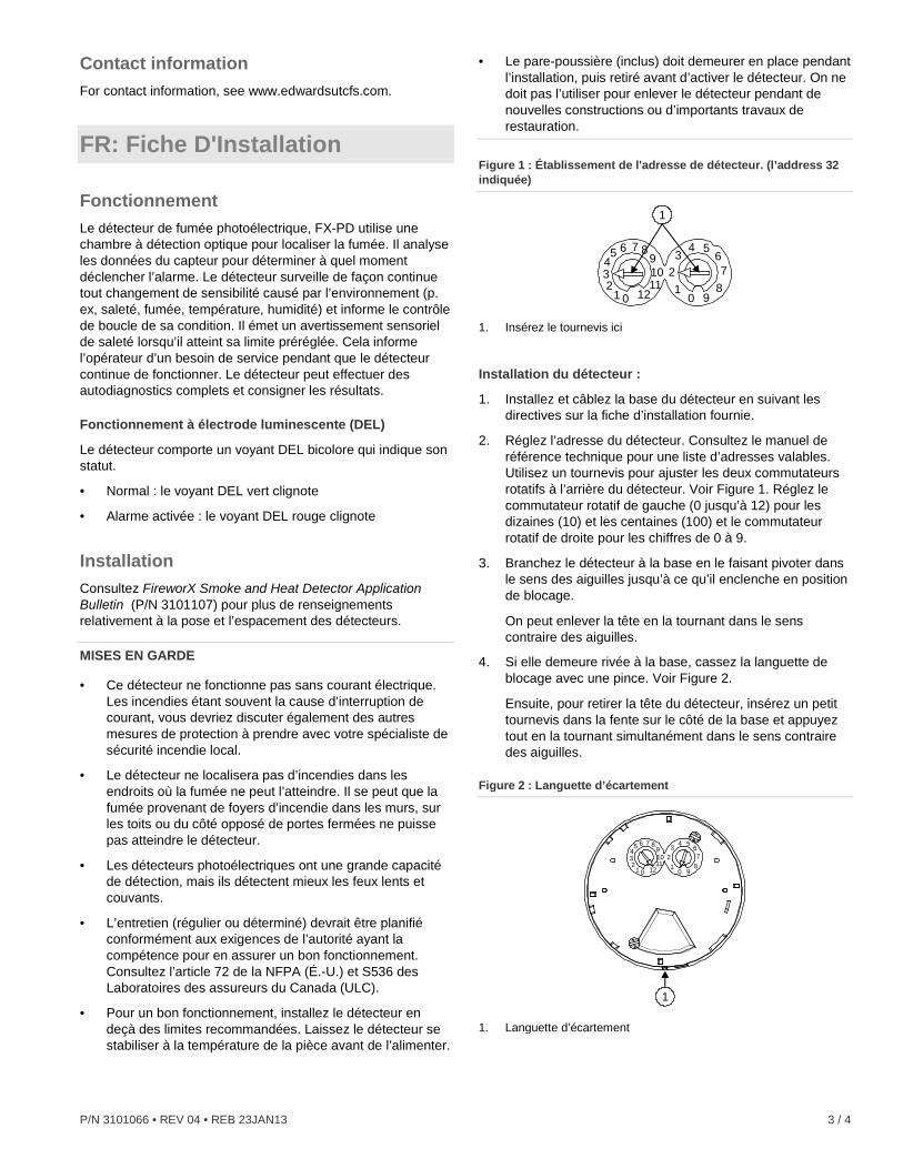
Figure 1 : Établissement de l'adresse de détecteur. (l’address 32 indiquée)
012
345 6
1211109
87
0 91
23
4 567
8
1
1. Insérez le tournevis ici
Installation du détecteur :
1. Installez et câblez la base du détecteur en suivant les directives sur la fiche d’installation fournie.
2. Réglez l’adresse du détecteur. Consultez le manuel de référence technique pour une liste d’adresses valables. Utilisez un tournevis pour ajuster les deux commutateurs rotatifs à l’arrière du détecteur. Voir Figure 1. Réglez le commutateur rotatif de gauche (0 jusqu’à 12) pour les dizaines (10) et les centaines (100) et le commutateur rotatif de droite pour les chiffres de 0 à 9.
3. Branchez le détecteur à la base en le faisant pivoter dans le sens des aiguilles jusqu’à ce qu’il enclenche en position de blocage.
On peut enlever la tête en la tournant dans le sens contraire des aiguilles.
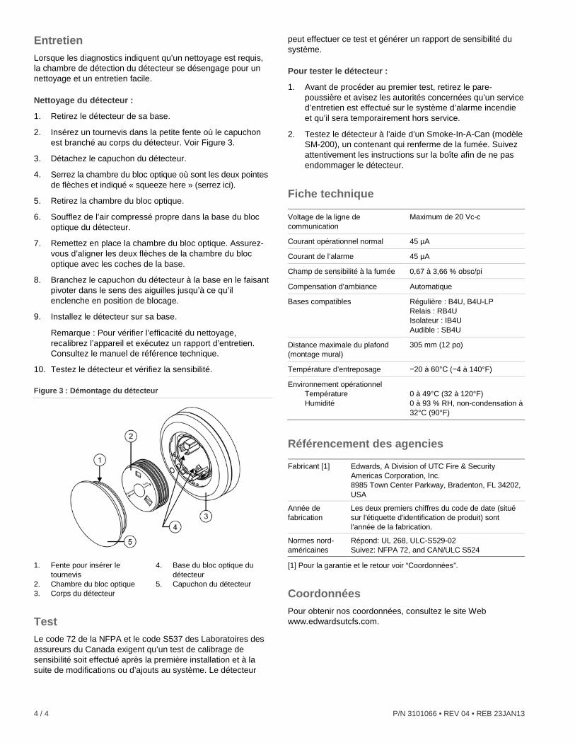
4. Si elle demeure rivée à la base, cassez la languette de blocage avec une pince. Voir Figure 2.
Ensuite, pour retirer la tête du détecteur, insérez un petit tournevis dans la fente sur le côté de la base et appuyez tout en la tournant simultanément dans le sens contraire des aiguilles.
Figure 2 : Languette d’écartement
1
012
34
5 6
1211109
87
0 91
23 4 5
67
8
1. Languette d’écartement
4 / 4 P/N 3101066 • REV 04 • REB 23JAN13
Entretien Lorsque les diagnostics indiquent qu’un nettoyage est requis, la chambre de détection du détecteur se désengage pour un nettoyage et un entretien facile.
Nettoyage du détecteur :
1. Retirez le détecteur de sa base.
2. Insérez un tournevis dans la petite fente où le capuchon est branché au corps du détecteur. Voir Figure 3.
3. Détachez le capuchon du détecteur.
4. Serrez la chambre du bloc optique où sont les deux pointes de flèches et indiqué « squeeze here » (serrez ici).
5. Retirez la chambre du bloc optique.
6. Soufflez de l’air compressé propre dans la base du bloc optique du détecteur.
7. Remettez en place la chambre du bloc optique. Assurez-vous d’aligner les deux flèches de la chambre du bloc optique avec les coches de la base.
8. Branchez le capuchon du détecteur à la base en le faisant pivoter dans le sens des aiguilles jusqu’à ce qu’il enclenche en position de blocage.
9. Installez le détecteur sur sa base.
Remarque : Pour vérifier l’efficacité du nettoyage, recalibrez l’appareil et exécutez un rapport d’entretien. Consultez le manuel de référence technique.
10. Testez le détecteur et vérifiez la sensibilité.
Figure 3 : Démontage du détecteur
1. Fente pour insérer le tournevis
2. Chambre du bloc optique 3. Corps du détecteur
4. Base du bloc optique du détecteur
5. Capuchon du détecteur
Test Le code 72 de la NFPA et le code S537 des Laboratoires des assureurs du Canada exigent qu’un test de calibrage de sensibilité soit effectué après la première installation et à la suite de modifications ou d’ajouts au système. Le détecteur
peut effectuer ce test et générer un rapport de sensibilité du système.
Pour tester le détecteur :
1. Avant de procéder au premier test, retirez le pare-poussière et avisez les autorités concernées qu’un service d’entretien est effectué sur le système d’alarme incendie et qu’il sera temporairement hors service.
2. Testez le détecteur à l’aide d’un Smoke-In-A-Can (modèle SM-200), un contenant qui renferme de la fumée. Suivez attentivement les instructions sur la boîte afin de ne pas endommager le détecteur.
Fiche technique Voltage de la ligne de communication
Maximum de 20 Vc-c
Courant opérationnel normal 45 µA
Courant de l’alarme 45 µA
Champ de sensibilité à la fumée 0,67 à 3,66 % obsc/pi
Compensation d’ambiance Automatique
Bases compatibles Régulière : B4U, B4U-LP Relais : RB4U Isolateur : IB4U Audible : SB4U
Distance maximale du plafond (montage mural)
305 mm (12 po)
Température d’entreposage −20 à 60°C (−4 à 140°F)
Environnement opérationnel Température Humidité
0 à 49°C (32 à 120°F) 0 à 93 % RH, non-condensation à 32°C (90°F)
Référencement des agencies Fabricant [1] Edwards, A Division of UTC Fire & Security
Americas Corporation, Inc. 8985 Town Center Parkway, Bradenton, FL 34202, USA
Année de fabrication
Les deux premiers chiffres du code de date (situé sur l'étiquette d'identification de produit) sont l'année de la fabrication.
Normes nord-américaines
Répond: UL 268, ULC-S529-02 Suivez: NFPA 72, and CAN/ULC S524
[1] Pour la garantie et le retour voir “Coordonnées”.
Coordonnées Pour obtenir nos coordonnées, consultez le site Web www.edwardsutcfs.com.