Embed Size (px)
Citation preview
G050016-00-R
Homodyne (DC) detection experiment at the 40 meter lab
Alan Weinstein for the 40m group and
Advanced Interferometer Configurations Working Group of the LSC
January 14, 2005
2G050016-00-R
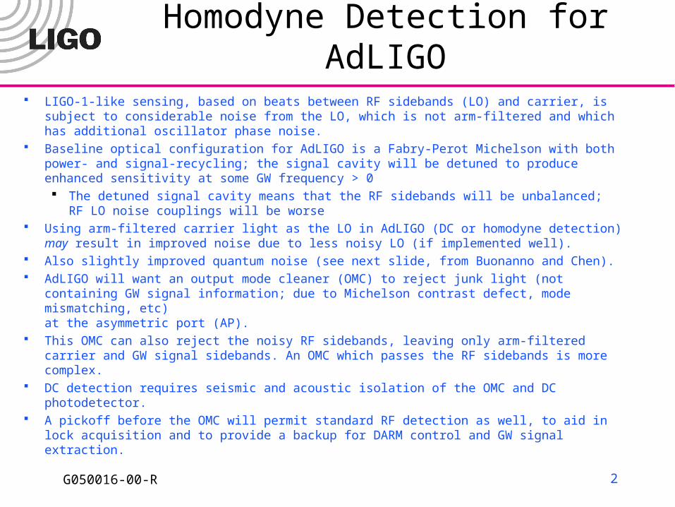
Homodyne Detection for AdLIGO LIGO-1-like sensing, based on beats between RF sidebands (LO) and carrier, is subject
to considerable noise from the LO, which is not arm-filtered and which has additional oscillator phase noise.
Baseline optical configuration for AdLIGO is a Fabry-Perot Michelson with both power- and signal-recycling; the signal cavity will be detuned to produce enhanced sensitivity at some GW frequency > 0 The detuned signal cavity means that the RF sidebands will be unbalanced;
RF LO noise couplings will be worse Using arm-filtered carrier light as the LO in AdLIGO (DC or homodyne detection)
may result in improved noise due to less noisy LO (if implemented well). Also slightly improved quantum noise (see next slide, from Buonanno and Chen). AdLIGO will want an output mode cleaner (OMC) to reject junk light (not containing GW
signal information; due to Michelson contrast defect, mode mismatching, etc) at the asymmetric port (AP).
This OMC can also reject the noisy RF sidebands, leaving only arm-filtered carrier and GW signal sidebands. An OMC which passes the RF sidebands is more complex.
DC detection requires seismic and acoustic isolation of the OMC and DC photodetector. A pickoff before the OMC will permit standard RF detection as well, to aid in lock
acquisition and to provide a backup for DARM control and GW signal extraction.

3G050016-00-R
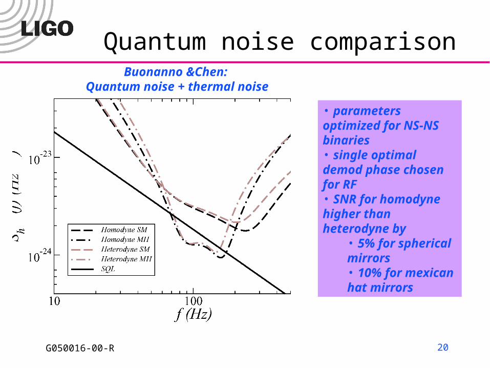
Quantum noise comparisonBuonanno &Chen:
Quantum noise + thermal noise
• parameters optimized for NS-NS binaries• single optimal demod phase chosen for RF• SNR for homodyne higher than heterodyne by
• 5% for spherical mirrors• 10% for mexican hat mirrors
4G050016-00-R
Goals for 40m The 40m is developing a full engineering prototype of the AdLIGO optical configuration. We expect to lock the full DRFPMI in the next few months, and establish a reliable lock
acquisition procedure for AdLIGO. Then, establish expected response to large-amplitude GWs. Then, study noise. This is a good time, and place, to test homodyne detection. Initial goal is to implement a DC detection optical beamline, sensing and control electronics.
This can be done on existing seismic stack in (small) vacuum chamber, already in place for this purpose.
Then, establish expected response to large-amplitude GWs, and first look at noise. Establishing low-noise sensing is another matter.
As everyone knows, finding and eliminating technical noise sources to the point where only fundamental noise sources remain, is a long, difficult, open-ended task.
Initial goal for 40m DRFPMI prototype with RF detection includes only an initial look at noise sources, not an exhaustive battle with them.
It is not clear how much can be learned about limits to noise in homodyne detection, in the 40 meter environment.
5G050016-00-R
Elements of DC detection beamline
Currently, light exiting the signal mirror goes straight out of the vacuum chamber and into an RF detection beamline (AP1) on a nearby optical table (mech shutter, EOS, HFRFPD, DDRFPD, QPD, CCD camera; see next slide).
Plan is to pick off some/most of that light, and send it into DC detection system. In-vac, seismically-isolated beamline (AP2):
Mode matching telescope (very short, off-axis mirrors, remote control focus) Two steering mirrors (PZT, servo-controlled) Output mode cleaner (3- or 4-mirror, fixed spacer, PZT-mounted mirror) DC detection photodiode (in a pressurized can?) with baffling.
OMC reflected beamline (on optical table in air): IF the OMC is to be locked using reflected sidebands, eg, 166 MHz,
then we need the usual: Mech shutter, electro-optic shutter and power PD, LSC RFPD, QPD, WFSs, CCD camera…
If the OMC is to be locked using dither locking, need DC PD instead, either in reflection or transmission.
6G050016-00-R
AP1 ISC System
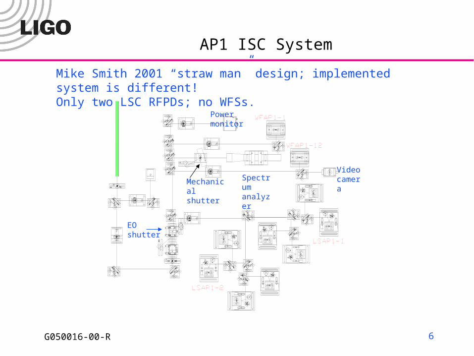
Spectrum analyzer
Video cameraMechanical
shutter
EO shutter
Power monitor
Mike Smith 2001 “straw man” design; implemented system is different!Only two LSC RFPDs; no WFSs.
7G050016-00-R
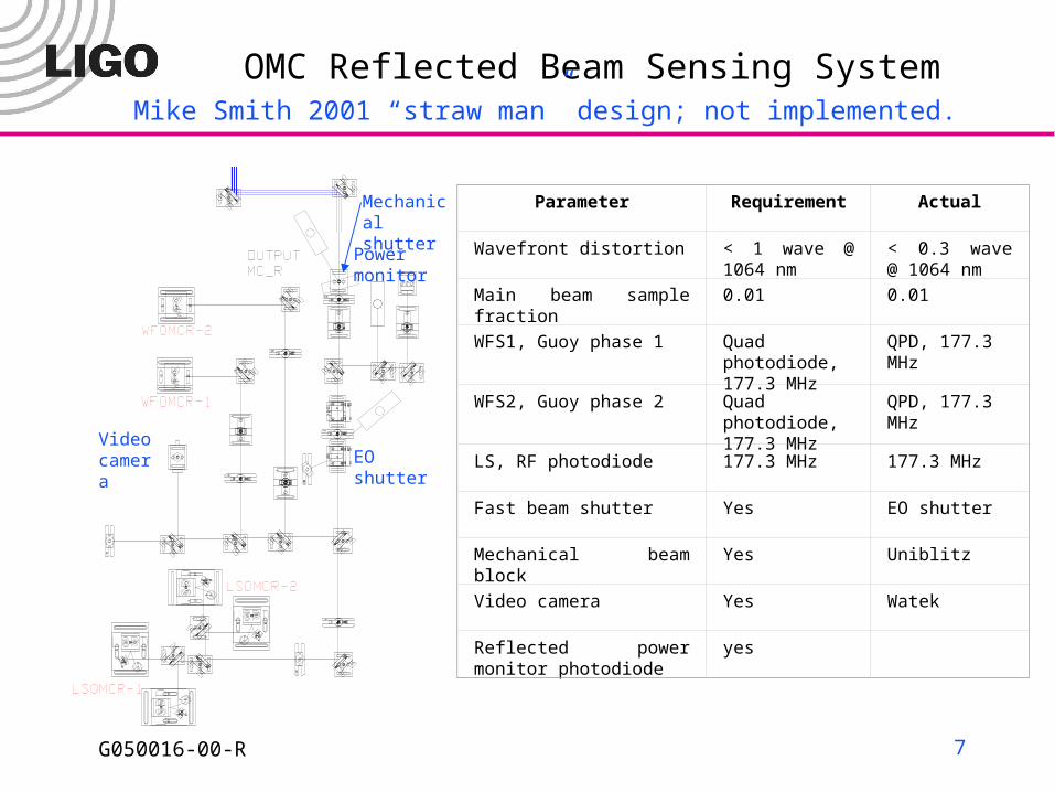
OMC Reflected Beam Sensing System
Parameter Requirement Actual
Wavefront distortion < 1 wave @ 1064 nm
< 0.3 wave @ 1064 nm
Main beam sample fraction 0.01 0.01
WFS1, Guoy phase 1 Quad photodiode, 177.3 MHz
QPD, 177.3 MHz
WFS2, Guoy phase 2 Quad photodiode, 177.3 MHz
QPD, 177.3 MHz
LS, RF photodiode 177.3 MHz 177.3 MHz
Fast beam shutter Yes EO shutter
Mechanical beam block Yes Uniblitz
Video camera Yes Watek
Reflected power monitor photodiode
yes
Video camera
Mechanical shutter
EO shutter
Power monitor
Mike Smith 2001 “straw man” design; not implemented.
8G050016-00-R
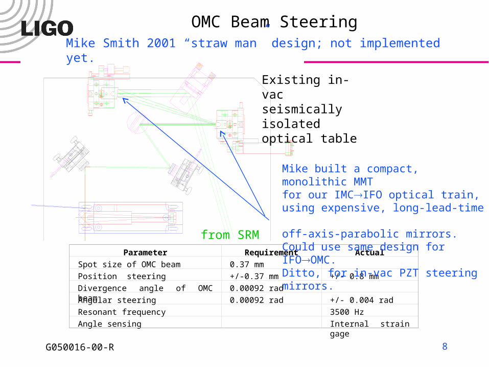
OMC Beam Steering
Parameter Requirement Actual
Spot size of OMC beam 0.37 mm
Position steering +/-0.37 mm +/- 0.8 mm
Divergence angle of OMC beam 0.00092 rad
Angular steering 0.00092 rad +/- 0.004 rad
Resonant frequency 3500 Hz
Angle sensing Internal strain gage
Mike Smith 2001 “straw man” design; not implemented yet.
Mike built a compact, monolithic MMT for our IMCIFO optical train,using expensive, long-lead-time off-axis-parabolic mirrors.Could use same design for IFOOMC.Ditto, for in-vac PZT steering mirrors.from SRM
Existing in-vac seismically isolated optical table
9G050016-00-R
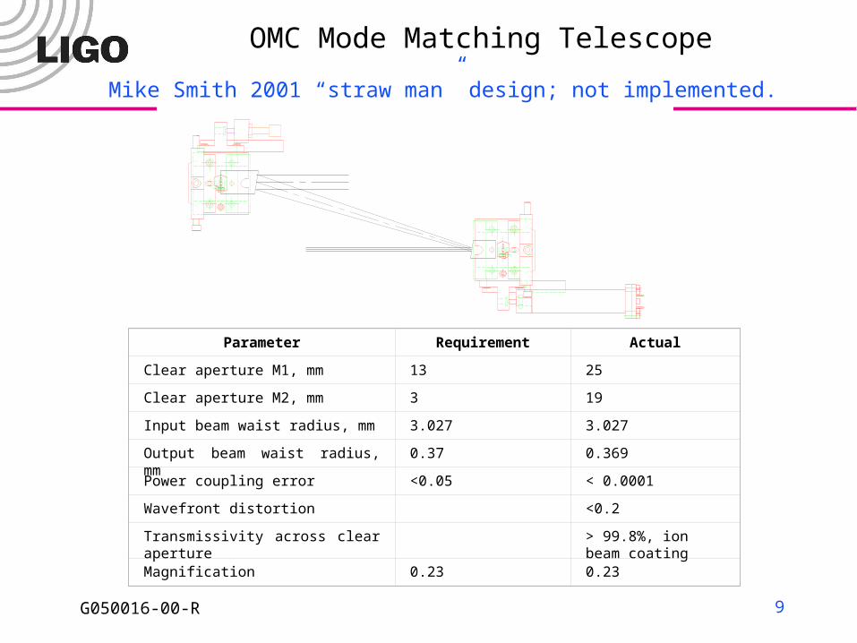
OMC Mode Matching Telescope
Parameter Requirement Actual
Clear aperture M1, mm 13 25
Clear aperture M2, mm 3 19
Input beam waist radius, mm 3.027 3.027
Output beam waist radius, mm 0.37 0.369
Power coupling error <0.05 < 0.0001
Wavefront distortion <0.2
Transmissivity across clear aperture > 99.8%, ion beam coating
Magnification 0.23 0.23
Mike Smith 2001 “straw man” design; not implemented.
10G050016-00-R
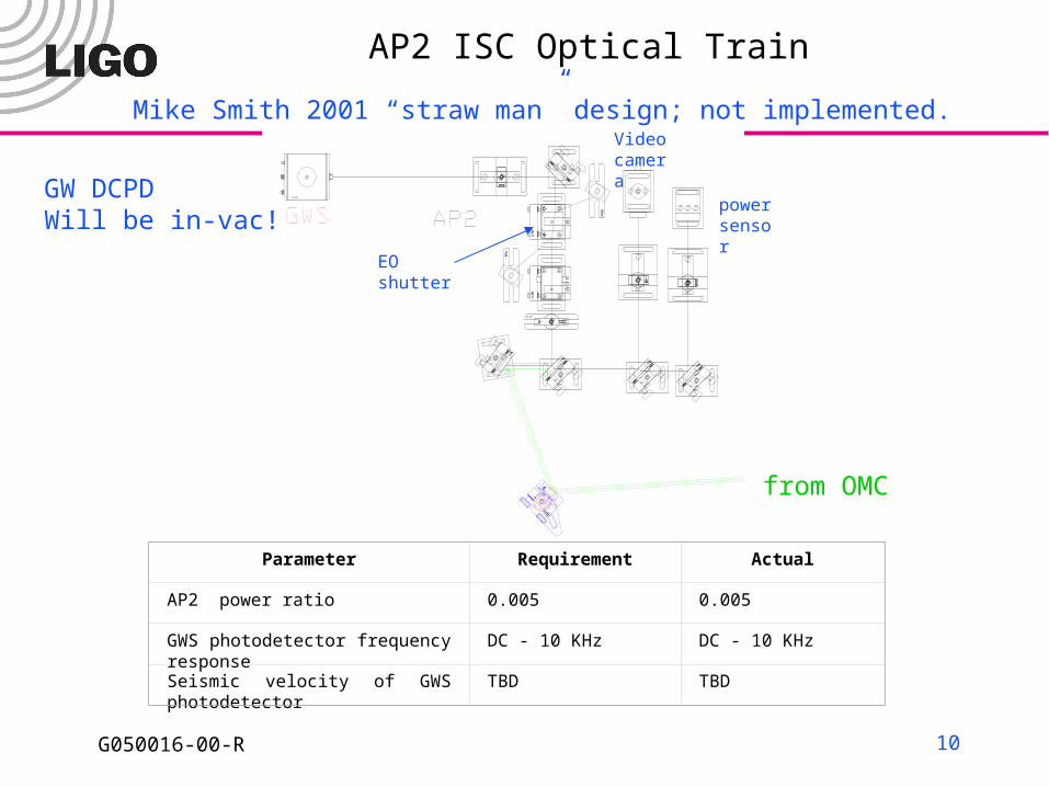
AP2 ISC Optical Train
Parameter Requirement Actual
AP2 power ratio 0.005 0.005
GWS photodetector frequency response DC - 10 KHz DC - 10 KHz
Seismic velocity of GWS photodetector TBD TBD
Video camera
power sensor
EO shutter
Mike Smith 2001 “straw man” design; not implemented.
GW DCPDWill be in-vac!
from OMC
11G050016-00-R
Many interesting questions First and foremost: given the 40m environment,
is the entire task worth pursuing? What will we learn? Assuming it is worth pursuing and that we will learn a lot… Is the overall scheme sensible? Other/better ways? Predict expected noise sources / couplings:
laser frequency and intensity noise Mach-Zehnder phase and amplitude noise MICH/PRC/SRC/DARM servo offset/noise OMC servo noise Using methods of Camp et al, Mason, Adhikari and Ballmer,…Kentaro Somiya accounts for full quantum noise effect, ala Buonanno&Chen.Must pursue in parallel with design and construction of engineering prototype of
homodyne detection. With DC detection, laser intensity noise feeds directly in to the GW signal;
it must be suppressed sufficiently well. Need DC photodiode on input light for intensity stabilization to AdLIGO spec.
OMC: 3-mirror or 4-mirror?
12G050016-00-R
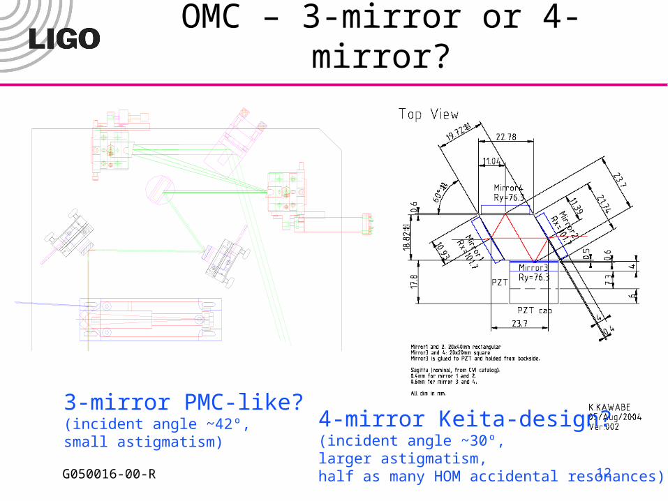
OMC – 3-mirror or 4-mirror?
3-mirror PMC-like?(incident angle ~42º,small astigmatism)
4-mirror Keita-design?(incident angle ~30º,larger astigmatism, half as many HOM accidental resonances)
13G050016-00-R
Many interesting questions / 2
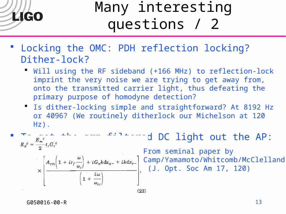
Locking the OMC: PDH reflection locking? Dither-lock? Will using the RF sideband (+166 MHz) to reflection-lock imprint the very
noise we are trying to get away from, onto the transmitted carrier light, thus defeating the primary purpose of homodyne detection?
Is dither-locking simple and straightforward? At 8192 Hz or 4096? (We routinely ditherlock our Michelson at 120 Hz).
To get the arm-filtered DC light out the AP: offset lock the arms? offset-lock the MICH?
From seminal paper byCamp/Yamamoto/Whitcomb/McClelland (J. Opt. Soc Am 17, 120)
14G050016-00-R
Better stop here
Following slides are Peter Fritschel’s talk from LSC meeting at Hannover, Aug 2003
G050016-00-R
DC Readout for Advanced LIGO
P Fritschel
LSC meeting
Hannover, 21 August 2003
16G050016-00-R
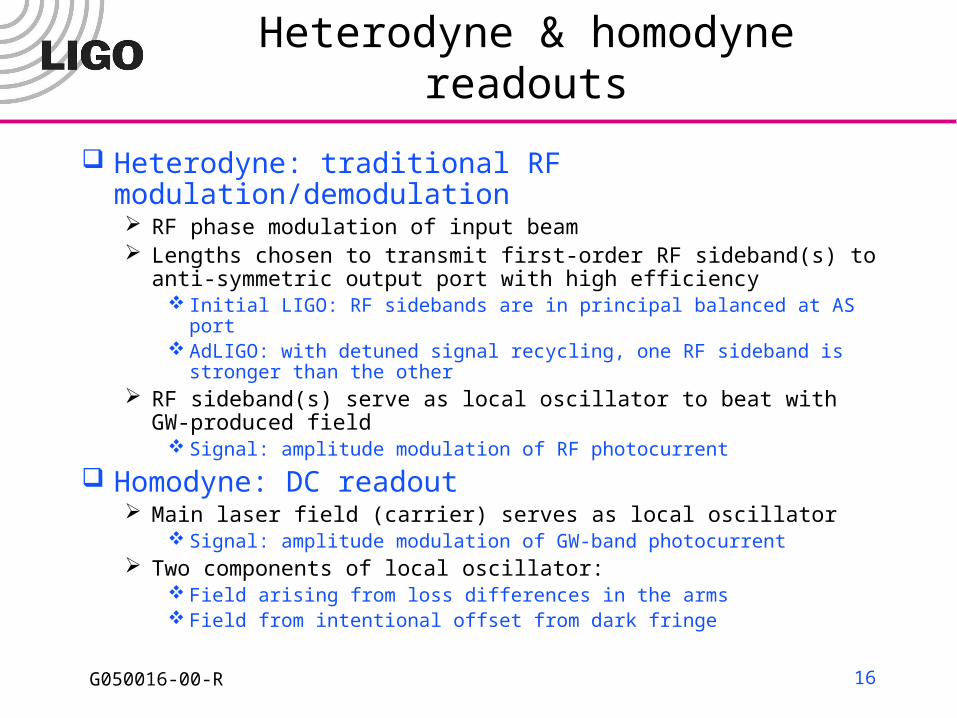
Heterodyne & homodyne readouts
Heterodyne: traditional RF modulation/demodulation RF phase modulation of input beam Lengths chosen to transmit first-order RF sideband(s) to anti-
symmetric output port with high efficiency Initial LIGO: RF sidebands are in principal balanced at AS port AdLIGO: with detuned signal recycling, one RF sideband is stronger
than the other RF sideband(s) serve as local oscillator to beat with GW-produced
field Signal: amplitude modulation of RF photocurrent
Homodyne: DC readout Main laser field (carrier) serves as local oscillator
Signal: amplitude modulation of GW-band photocurrent Two components of local oscillator:
Field arising from loss differences in the arms Field from intentional offset from dark fringe
17G050016-00-R
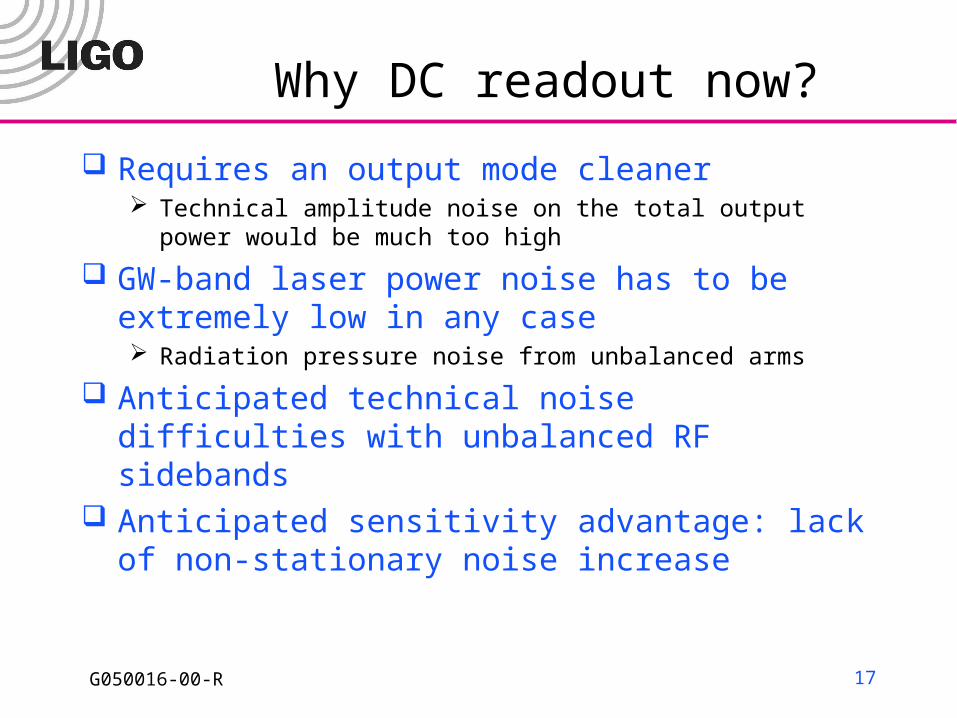
Why DC readout now?
Requires an output mode cleaner Technical amplitude noise on the total output power would be much
too high
GW-band laser power noise has to be extremely low in any case Radiation pressure noise from unbalanced arms
Anticipated technical noise difficulties with unbalanced RF sidebands
Anticipated sensitivity advantage: lack of non-stationary noise increase
18G050016-00-R
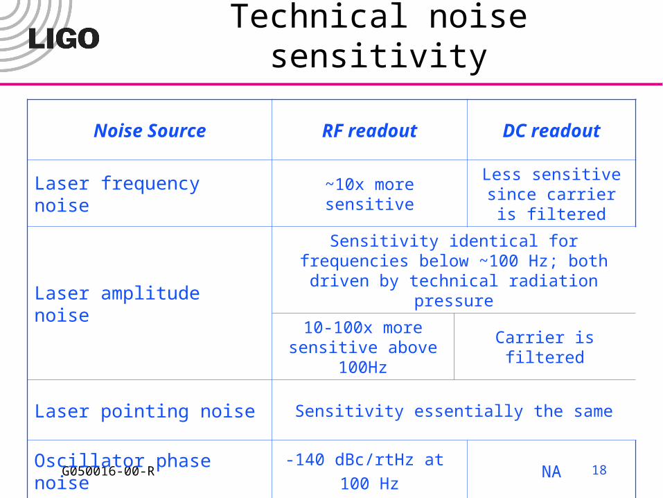
Technical noise sensitivity
Noise Source RF readout DC readout
Laser frequency noise ~10x more sensitiveLess sensitive since
carrier is filtered
Laser amplitude noise
Sensitivity identical for frequencies below ~100 Hz; both driven by technical radiation pressure
10-100x more sensitive above 100Hz
Carrier is filtered
Laser pointing noise Sensitivity essentially the same
Oscillator phase noise-140 dBc/rtHz at
100 HzNA
19G050016-00-R
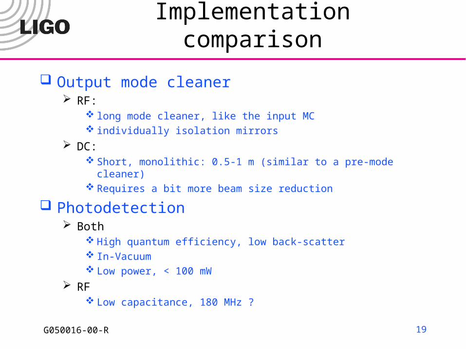
Implementation comparison
Output mode cleaner RF:
long mode cleaner, like the input MC individually isolation mirrors
DC: Short, monolithic: 0.5-1 m (similar to a pre-mode cleaner) Requires a bit more beam size reduction
Photodetection Both
High quantum efficiency, low back-scatter In-Vacuum Low power, < 100 mW
RF Low capacitance, 180 MHz ?
20G050016-00-R
Quantum noise comparisonBuonanno &Chen:
Quantum noise + thermal noise
• parameters optimized for NS-NS binaries• single optimal demod phase chosen for RF• SNR for homodyne higher than heterodyne by
• 5% for spherical mirrors• 10% for mexican hat mirrors
21G050016-00-R
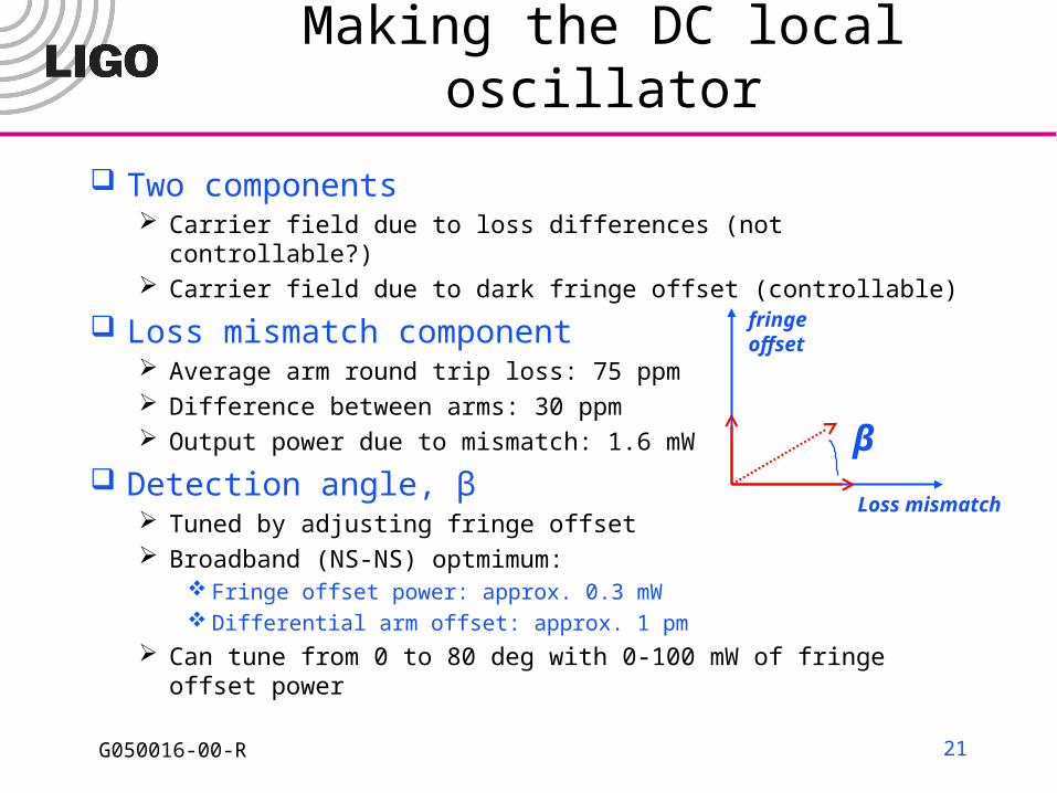
Making the DC local oscillator
Two components Carrier field due to loss differences (not controllable?) Carrier field due to dark fringe offset (controllable)
Loss mismatch component Average arm round trip loss: 75 ppm Difference between arms: 30 ppm Output power due to mismatch: 1.6 mW
Detection angle, β Tuned by adjusting fringe offset Broadband (NS-NS) optmimum:
Fringe offset power: approx. 0.3 mW Differential arm offset: approx. 1 pm
Can tune from 0 to 80 deg with 0-100 mW of fringe offset power
Loss mismatch
fringeoffset
β
22G050016-00-R
Summary
Sensitivity of a DC readout is a ‘little better’ than that of an RF readout: 5-10%
Technical noise sensitivity favors DC readout Technical implementation favors DC readout Proceeding with DC readout as baseline design
Output mode cleaner design: Vibration isolation Sensing and control: length and alignment
Could we switch later to RF readout? Hardest part would be changing the output mode cleaner (to pass the RF sidebands)