Embed Size (px)
Citation preview
G8JCFSDR Build 205+
Quick Start Guide
Updated for
ELEKTOR July/August 2016 SDR Shield
29 March 2017
Table of Contents
1 INTRODUCTION .................................................................................................................................................................. 3
2 GENERAL OPERATION OF CONTROLS ....................................................................................................................... 4
2.1 GENERAL OPERATION OF CONTROLS ................................................................................................................................ 4 2.2 SCROLLABLE LABELS ........................................................................................................................................................ 4 2.3 SLIDER CONTROLS ............................................................................................................................................................ 4 2.4 DIAL CONTROLS ................................................................................................................................................................ 5
3 FREQUENCY CONTROL .................................................................................................................................................... 6
3.1.1 Free Tuning .............................................................................................................................................................. 6 3.1.2 Setting the Tuning Step or Rate ................................................................................................................................ 6
3.2 POINT ‘N CLICK ................................................................................................................................................................. 7 3.3 SLIDE ‘N TUNE .................................................................................................................................................................. 7 3.4 PRESETS ............................................................................................................................................................................ 8 3.5 VIRTUAL TUNING DIAL ..................................................................................................................................................... 8 3.6 RIT .................................................................................................................................................................................... 8 3.7 IMAGE REJECTION - AKA I/Q BALANCE ....................................................................................................................... 8
4 CONFIGURING G8JCFSDR FOR USE WITH ELEKTOR MAY 2007 IQ USB SDR DOWN-CONVERTER ....... 11
4.1 OBTAINING THE G8JCFSDR. .......................................................................................................................................... 11 4.2 RUNNING THE G8JCFSDR .............................................................................................................................................. 11 4.3 FIRST TIME RUN OF G8JCFSDR ..................................................................................................................................... 11 4.4 CONFIGURING THE G8JCFSDR ....................................................................................................................................... 12 4.5 CALIBRATION .................................................................................................................................................................. 15
4.5.1 Image Rejection Calibration ................................................................................................................................... 15 4.5.2 Phase Correction .................................................................................................................................................... 19 4.5.3 Amplitude Correction ............................................................................................................................................. 19 4.5.4 Frequency Calibration............................................................................................................................................ 19 4.5.5 SMeter Calibration ................................................................................................................................................. 21
5 CONFIGURING G8JCFSDR FOR USE WITH ELEKTOR SDR SHIELD .................................................................. 22
6 DRM - DIGITAL RADIO MONDIALE ............................................................................................................................ 28
1 Introduction
The G8JCFSDR is a software implementation of a conventional radio, Software Defined Radio, using Digital Signal Processing techniques. Modern Personal; Computers are so powerful, that what was once only possible in the realm of the specialist engineer, is now easily carried out on any general purpose PC. The G8JCFSDR in conjunction with simple down-converter hardware provides an extremely cost-effective, incredibly flexible and versatile receiver combination. Because the radio is implemented in software, features which would be prohibitively expensive or almost impossible to implement in hardware become simply a matter of programming and CPU/Memory consumption, eg fully variable filters with 50Hz skirts.
The G8JCFSDR is optimised for HF communications, although with suitable down-converters there is no reason why other frequency ranges cannot be handled.
This guide focuses on using the G8JCFSDR in combination with the Elektor May 2007 IQ USB down-converter, and the Elektor July 2016 SDR Shield - aka SDR Reloaded - however much of what is written here applies to any other down-converter.
I have many different down-converters here, some which I have designed and built myself, some purchased, and some sent to me. I can say that from a price/performance and feature perspective, the Elektor 5/2007 USB down-converter is right up there at the top of the pile, and after 40 years of playing about with radios, this is the first radio I have ever owned which has a calibrated S-Meter !!
I hope you enjoy using the G8JCFSDR as much as I have enjoyed writing it and re-learning so much about Fourier !
Thank You
Peter GM8JCF
All material herein is © 2017 Peter Carnegie
2 General Operation of Controls
The G8JCFSDR tries to perform as close as possible to a real HF communications receiver within the constraints of not having real knobs and dials of course !
2.1 General Operation of Controls
Most of the controls used in the G8JCFSDR are standard windows controls, eg Checkboxes, Radio Buttons, Buttons and so on. These controls work exactly as you would expect.
2.2 Scrollable Labels
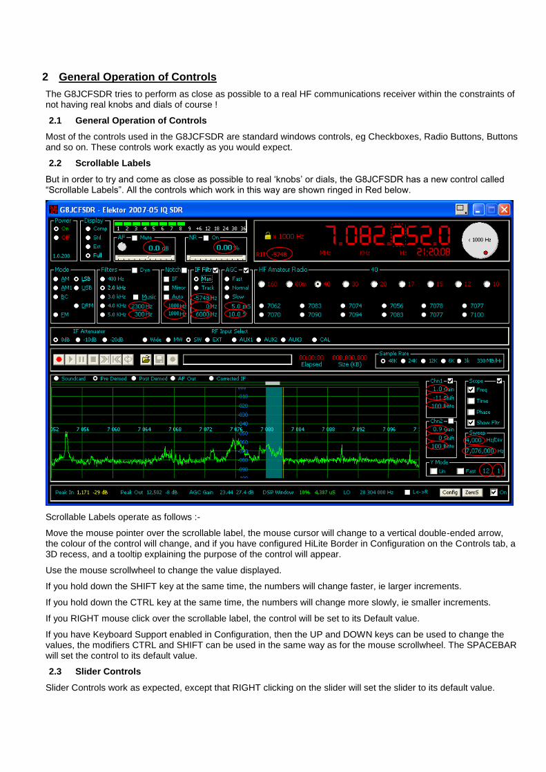
But in order to try and come as close as possible to real ‘knobs’ or dials, the G8JCFSDR has a new control called “Scrollable Labels”. All the controls which work in this way are shown ringed in Red below.
Scrollable Labels operate as follows :-
Move the mouse pointer over the scrollable label, the mouse cursor will change to a vertical double-ended arrow, the colour of the control will change, and if you have configured HiLite Border in Configuration on the Controls tab, a 3D recess, and a tooltip explaining the purpose of the control will appear.
Use the mouse scrollwheel to change the value displayed.
If you hold down the SHIFT key at the same time, the numbers will change faster, ie larger increments.
If you hold down the CTRL key at the same time, the numbers will change more slowly, ie smaller increments.
If you RIGHT mouse click over the scrollable label, the control will be set to its Default value.
If you have Keyboard Support enabled in Configuration, then the UP and DOWN keys can be used to change the values, the modifiers CTRL and SHIFT can be used in the same way as for the mouse scrollwheel. The SPACEBAR will set the control to its default value.
2.3 Slider Controls
Slider Controls work as expected, except that RIGHT clicking on the slider will set the slider to its default value.

2.4 Dial Controls
Dial Controls are used in the Virtual Tuning Dial, the AF output level control, and the Noise Reduction Control. To use these controls, move the mouse over the dial, then press and hold down the LEFT mouse button, now drag the dial around in a circular motion to change its value. The dial controls have been provided because they can be rather than being the only way of doing something, generally it’s much more convenient and easier to use the scrollable label equivalent.
3 Frequency Control
The G8JCFSDR may be tuned in many ways
Scrollwheel over the frequency display
Keyboard UP/DOWN arrow keys
Virtual Tuning Knob
Point ‘n Click
Slide ‘n Tune
Receiver Incremental Tuning, RIT
Presets
3.1.1 Free Tuning
Make sure the Yellow Padlock is not visible by single clicking over the Frequency Display. Then as you move the mouse across the Frequency Display, the red dashed bounding box will move with your mouse pointer showing the digit over which the mouse is located. At the same time, the tuning step which will be used is shown on the face of the Virtual Tuning Dial, and also at the right hand side of the frequency display. In this way you can tune with a precision or increment of 1dHz, 1Hz, 10Hz, 100Hz, 1KHz, 10KHz, 100KHz, 1MHz, and 10MHz. If you have enabled Keyboard Support in Configuration, then U can use the UP & DOWN arrow keys instead of the scrollwheel, and the LEFT & RIGHT keys to select the digit.
3.1.2 Setting the Tuning Step or Rate
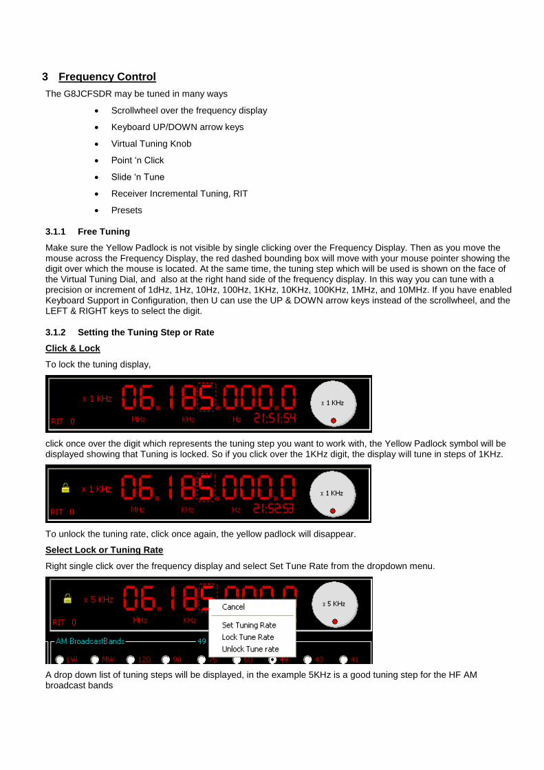
Click & Lock
To lock the tuning display,
click once over the digit which represents the tuning step you want to work with, the Yellow Padlock symbol will be displayed showing that Tuning is locked. So if you click over the 1KHz digit, the display will tune in steps of 1KHz.
To unlock the tuning rate, click once again, the yellow padlock will disappear.
Select Lock or Tuning Rate
Right single click over the frequency display and select Set Tune Rate from the dropdown menu.
A drop down list of tuning steps will be displayed, in the example 5KHz is a good tuning step for the HF AM broadcast bands
Select the required Tuning Step. Next to the Yellow Padlock, the selected tuning step will be displayed. The centre of the virtual tuning knob will also show the selected tuning rate. Now when you change the frequency using the scrollwheel or UP/DOWN arrows, the frequency will change in steps of the selected tuning step, in this example 5KHz.
Right clicking over the virtual tuning knob will also enable you to select a tuning step as previously described.
3.1.2.1 Keyboard UP/DOWN arrow keys
Move the cursor over the digit in the Frequency Display, then use the UP and DOWN arrow keys to change the digit. Use LEFT & RIGHT arrow keys to select which digit to change. SPACEBAR locks the tuning step.
3.2 Point ‘n Click
Point the mouse at the signal of interest on the Spectrum Analyser, and LEFT mouse click once
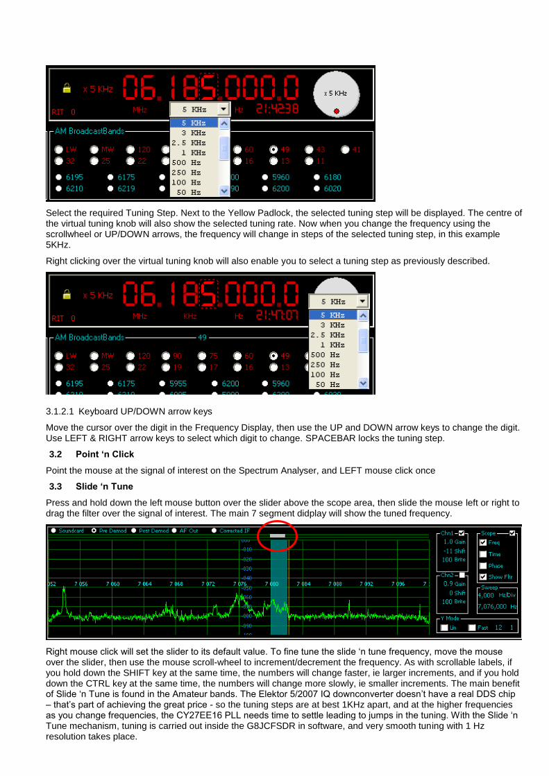
3.3 Slide ‘n Tune
Press and hold down the left mouse button over the slider above the scope area, then slide the mouse left or right to drag the filter over the signal of interest. The main 7 segment didplay will show the tuned frequency.
Right mouse click will set the slider to its default value. To fine tune the slide ‘n tune frequency, move the mouse over the slider, then use the mouse scroll-wheel to increment/decrement the frequency. As with scrollable labels, if you hold down the SHIFT key at the same time, the numbers will change faster, ie larger increments, and if you hold down the CTRL key at the same time, the numbers will change more slowly, ie smaller increments. The main benefit of Slide ‘n Tune is found in the Amateur bands. The Elektor 5/2007 IQ downconverter doesn’t have a real DDS chip – that’s part of achieving the great price - so the tuning steps are at best 1KHz apart, and at the higher frequencies as you change frequencies, the CY27EE16 PLL needs time to settle leading to jumps in the tuning. With the Slide ‘n Tune mechanism, tuning is carried out inside the G8JCFSDR in software, and very smooth tuning with 1 Hz resolution takes place.
3.4 Presets
Select the Main Band, eg Broadcast Bands, then select the sub-band, eg 41m, then click on one of the radio buttons. To store a frequency into a preset, single left mouse click on a preset whilst holding down the SHIFT key. To edit a preset, RIGHT mouse click over a preset and follow the drop down menu.
3.5 Virtual Tuning Dial
Press and hold down the left mouse button over the Virtual Tuning Dial, and then drag the dial round in a circular motion
3.6 RIT
The RIT is a scrollable label allowing +12KHz –12KHz tuning without changing the main VFO frequency
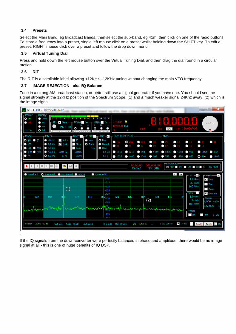
3.7 IMAGE REJECTION - aka I/Q Balance
Tune in a strong AM broadcast station, or better still use a signal generator if you have one. You should see the signal strongly at the 12KHz position of the Spectrum Scope, (1) and a much weaker signal 24Khz away, (2) which is the image signal.
.
If the IQ signals from the down-converter were perfectly balanced in phase and amplitude, there would be no image signal at all - this is one of huge benefits of IQ DSP.
(1)
(2)
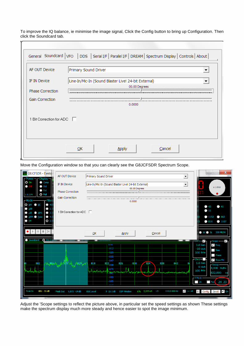
To improve the IQ balance, ie minimise the image signal, Click the Config button to bring up Configuration. Then click the Soundcard tab.
Move the Configuration window so that you can clearly see the G8JCFSDR Spectrum Scope.
Adjust the 'Scope settings to reflect the picture above, in particular set the speed settings as shown These settings make the spectrum display much more steady and hence easier to spot the image minimum.
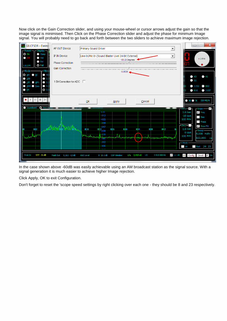
Now click on the Gain Correction slider, and using your mouse-wheel or cursor arrows adjust the gain so that the image signal is minimised. Then Click on the Phase Correction slider and adjust the phase for minimum Image signal. You will probably need to go back and forth between the two sliders to achieve maximum image rejection.
In the case shown above -60dB was easily achievable using an AM broadcast station as the signal source. With a signal generation it is much easier to achieve higher Image rejection.
Click Apply, OK to exit Configuration.
Don't forget to reset the 'scope speed settings by right clicking over each one - they should be 8 and 23 respectively.
4 Configuring G8JCFSDR for use with ELEKTOR May 2007 IQ USB SDR Down-Converter
This document is a short user guide to using the G8JCFSDR with the ELEKTOR May 2007 IQ USB SDR Down-Converter.
4.1 Obtaining the G8JCFSDR.
The G8JCFSDR software may be downloaded from http://www.g8jcf.dyndns.org. If you are running Microsoft Vista then you will also need to install a key file of DirectX8. The file c:\windows\system32\DX8VB.DLL is not part of the standard VISTA OS and must be manually installed. The simplest thing to do, is to Google for VISTA DX8VB.DLL DOWNLOAD and download it. Then register the DLL using regsvr32 c:\windows\system32\DX8VB.DLL. If there are any other Vista specifics, they will notified on the Vista issues page at http://www.g8jcf.dyndns.org.
4.2 Running the G8JCFSDR
Using the Start Menu, find G8JCF, then select the G8JCFSDR programme.
4.3 First Time Run of G8JCFSDR
If this is the first time you have ever run the G8JCFSDR, then it will initialise itself to default values.
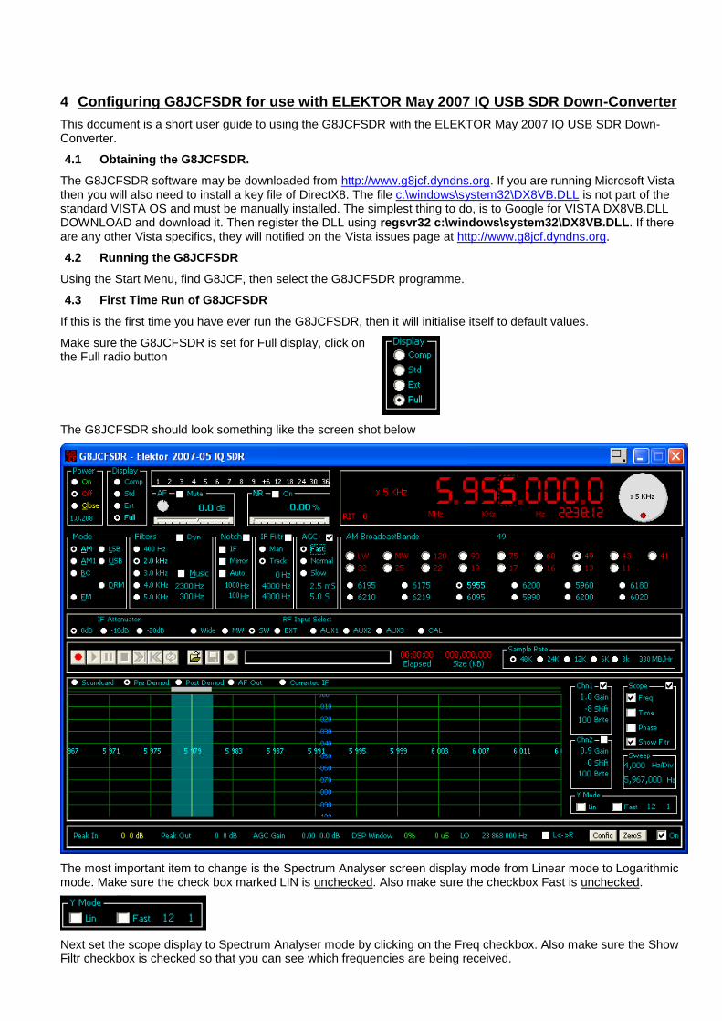
Make sure the G8JCFSDR is set for Full display, click on the Full radio button
The G8JCFSDR should look something like the screen shot below
The most important item to change is the Spectrum Analyser screen display mode from Linear mode to Logarithmic mode. Make sure the check box marked LIN is unchecked. Also make sure the checkbox Fast is unchecked.
Next set the scope display to Spectrum Analyser mode by clicking on the Freq checkbox. Also make sure the Show Filtr checkbox is checked so that you can see which frequencies are being received.
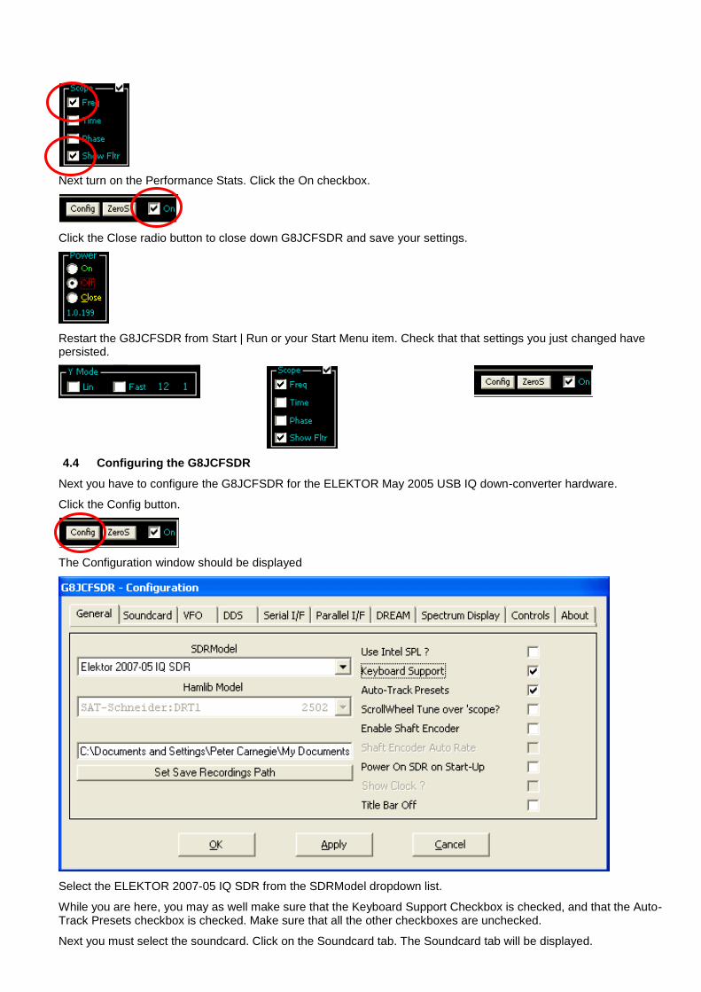
Next turn on the Performance Stats. Click the On checkbox.
Click the Close radio button to close down G8JCFSDR and save your settings.
Restart the G8JCFSDR from Start | Run or your Start Menu item. Check that that settings you just changed have persisted.
4.4 Configuring the G8JCFSDR
Next you have to configure the G8JCFSDR for the ELEKTOR May 2005 USB IQ down-converter hardware.
Click the Config button.
The Configuration window should be displayed
Select the ELEKTOR 2007-05 IQ SDR from the SDRModel dropdown list.
While you are here, you may as well make sure that the Keyboard Support Checkbox is checked, and that the Auto-Track Presets checkbox is checked. Make sure that all the other checkboxes are unchecked.
Next you must select the soundcard. Click on the Soundcard tab. The Soundcard tab will be displayed.
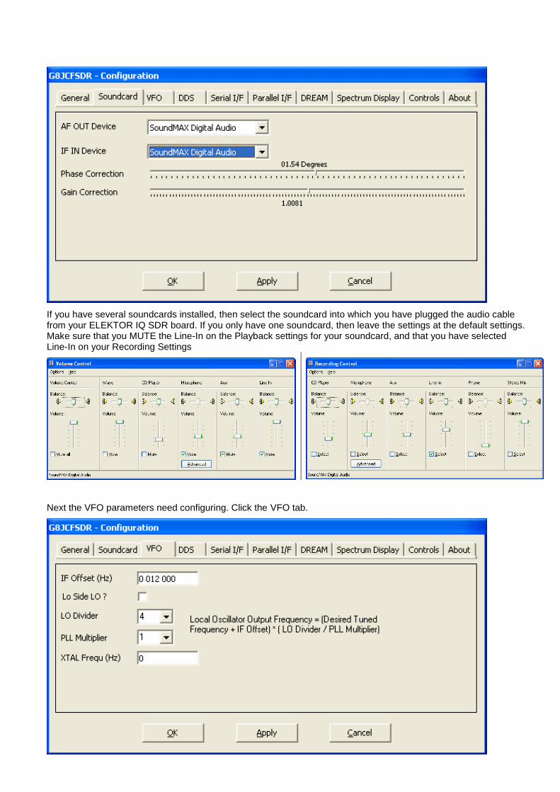
If you have several soundcards installed, then select the soundcard into which you have plugged the audio cable from your ELEKTOR IQ SDR board. If you only have one soundcard, then leave the settings at the default settings. Make sure that you MUTE the Line-In on the Playback settings for your soundcard, and that you have selected Line-In on your Recording Settings
Next the VFO parameters need configuring. Click the VFO tab.
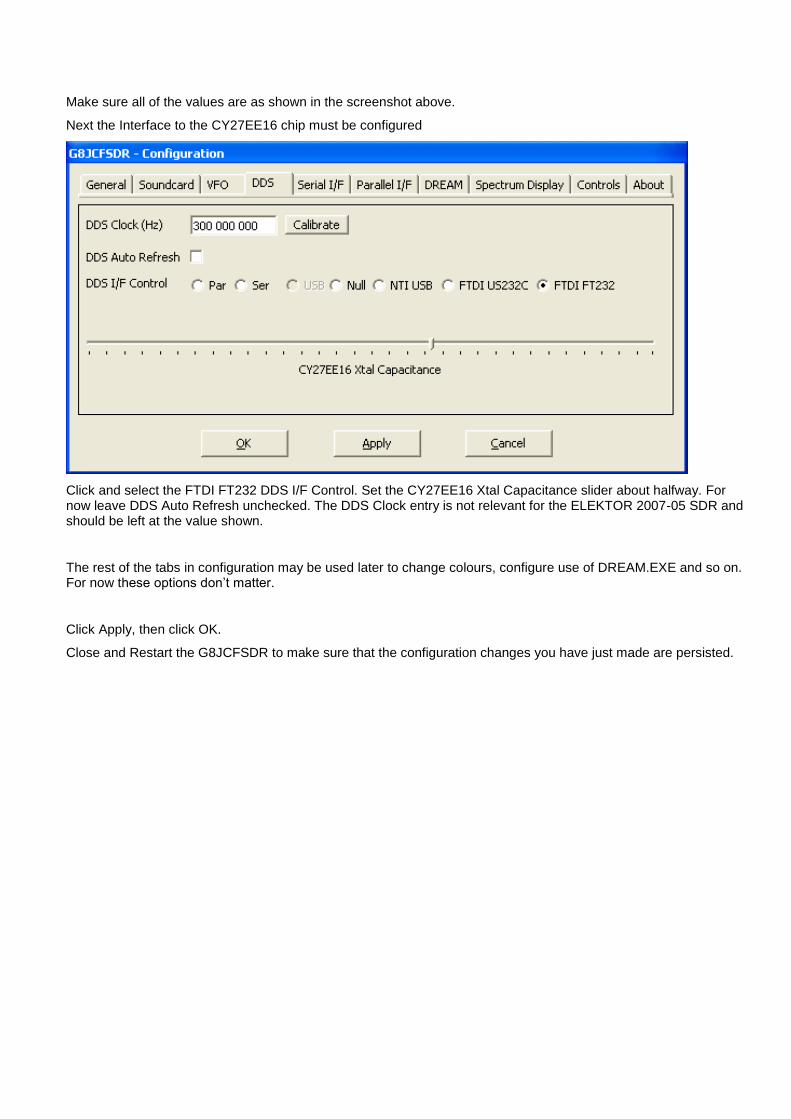
Make sure all of the values are as shown in the screenshot above.
Next the Interface to the CY27EE16 chip must be configured
Click and select the FTDI FT232 DDS I/F Control. Set the CY27EE16 Xtal Capacitance slider about halfway. For now leave DDS Auto Refresh unchecked. The DDS Clock entry is not relevant for the ELEKTOR 2007-05 SDR and should be left at the value shown.
The rest of the tabs in configuration may be used later to change colours, configure use of DREAM.EXE and so on. For now these options don’t matter.
Click Apply, then click OK.
Close and Restart the G8JCFSDR to make sure that the configuration changes you have just made are persisted.
4.5 Calibration
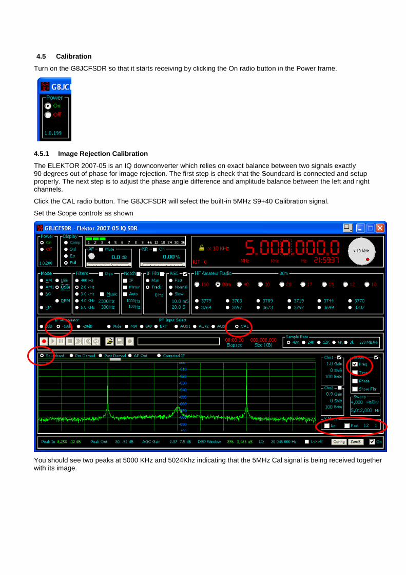
Turn on the G8JCFSDR so that it starts receiving by clicking the On radio button in the Power frame.
4.5.1 Image Rejection Calibration
The ELEKTOR 2007-05 is an IQ downconverter which relies on exact balance between two signals exactly 90 degrees out of phase for image rejection. The first step is check that the Soundcard is connected and setup properly. The next step is to adjust the phase angle difference and amplitude balance between the left and right channels.
Click the CAL radio button. The G8JCFSDR will select the built-in 5MHz S9+40 Calibration signal.
Set the Scope controls as shown
You should see two peaks at 5000 KHz and 5024Khz indicating that the 5MHz Cal signal is being received together with its image.
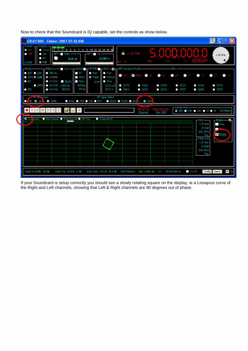
Now to check that the Soundcard is IQ capable, set the controls as show below.
If your Soundcard is setup correctly you should see a slowly rotating square on the display, ie a Lissajous curve of the Right and Left channels, showing that Left & Right channels are 90 degrees out of phase.
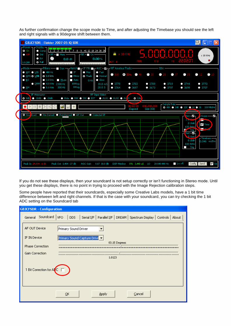
As further confirmation change the scope mode to Time, and after adjusting the Timebase you should see the left and right signals with a 90degree shift between them.
If you do not see these displays, then your soundcard is not setup correctly or isn’t functioning in Stereo mode. Until you get these displays, there is no point in trying to proceed with the Image Rejection calibration steps.
Some people have reported that their soundcards, especially some Creative Labs models, have a 1 bit time difference between left and right channels. If that is the case with your soundcard, you can try checking the 1 bit ADC setting on the Soundcard tab
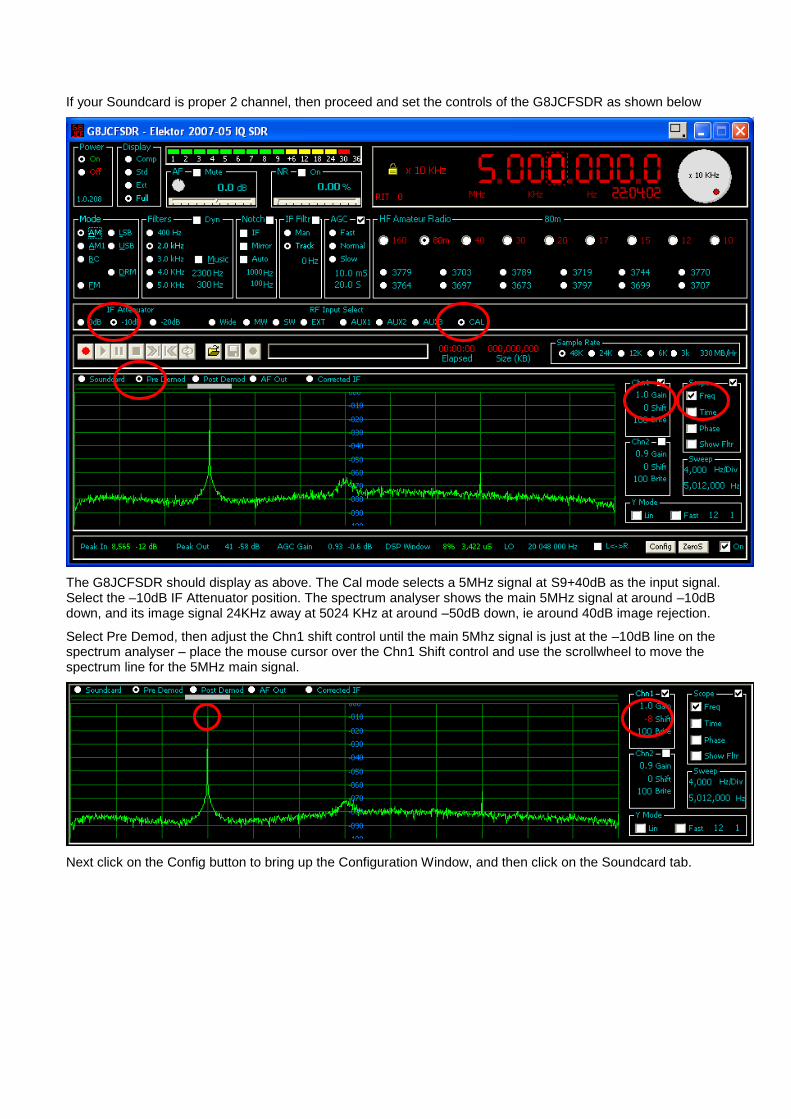
If your Soundcard is proper 2 channel, then proceed and set the controls of the G8JCFSDR as shown below
The G8JCFSDR should display as above. The Cal mode selects a 5MHz signal at S9+40dB as the input signal. Select the –10dB IF Attenuator position. The spectrum analyser shows the main 5MHz signal at around –10dB down, and its image signal 24KHz away at 5024 KHz at around –50dB down, ie around 40dB image rejection.
Select Pre Demod, then adjust the Chn1 shift control until the main 5Mhz signal is just at the –10dB line on the spectrum analyser – place the mouse cursor over the Chn1 Shift control and use the scrollwheel to move the spectrum line for the 5MHz main signal.
Next click on the Config button to bring up the Configuration Window, and then click on the Soundcard tab.
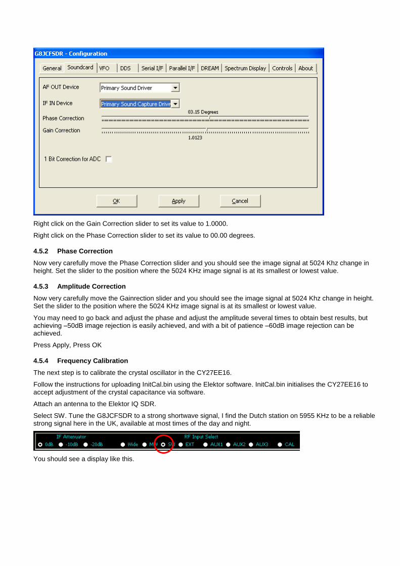
Right click on the Gain Correction slider to set its value to 1.0000.
Right click on the Phase Correction slider to set its value to 00.00 degrees.
4.5.2 Phase Correction
Now very carefully move the Phase Correction slider and you should see the image signal at 5024 Khz change in height. Set the slider to the position where the 5024 KHz image signal is at its smallest or lowest value.
4.5.3 Amplitude Correction
Now very carefully move the Gainrection slider and you should see the image signal at 5024 Khz change in height. Set the slider to the position where the 5024 KHz image signal is at its smallest or lowest value.
You may need to go back and adjust the phase and adjust the amplitude several times to obtain best results, but achieving –50dB image rejection is easily achieved, and with a bit of patience –60dB image rejection can be achieved.
Press Apply, Press OK
4.5.4 Frequency Calibration
The next step is to calibrate the crystal oscillator in the CY27EE16.
Follow the instructions for uploading InitCal.bin using the Elektor software. InitCal.bin initialises the CY27EE16 to accept adjustment of the crystal capacitance via software.
Attach an antenna to the Elektor IQ SDR.
Select SW. Tune the G8JCFSDR to a strong shortwave signal, I find the Dutch station on 5955 KHz to be a reliable strong signal here in the UK, available at most times of the day and night.
You should see a display like this.
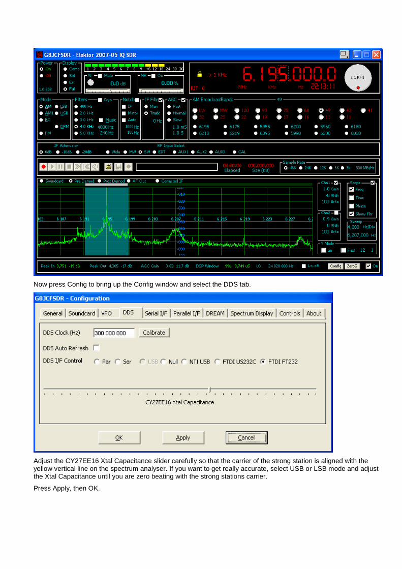
Now press Config to bring up the Config window and select the DDS tab.
Adjust the CY27EE16 Xtal Capacitance slider carefully so that the carrier of the strong station is aligned with the yellow vertical line on the spectrum analyser. If you want to get really accurate, select USB or LSB mode and adjust the Xtal Capacitance until you are zero beating with the strong stations carrier.
Press Apply, then OK.
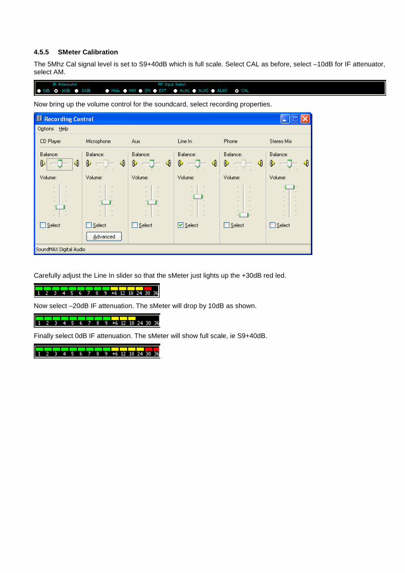
4.5.5 SMeter Calibration
The 5Mhz Cal signal level is set to S9+40dB which is full scale. Select CAL as before, select –10dB for IF attenuator, select AM.
Now bring up the volume control for the soundcard, select recording properties.
Carefully adjust the Line In slider so that the sMeter just lights up the +30dB red led.
Now select –20dB IF attenuation. The sMeter will drop by 10dB as shown.
Finally select 0dB IF attenuation. The sMeter will show full scale, ie S9+40dB.
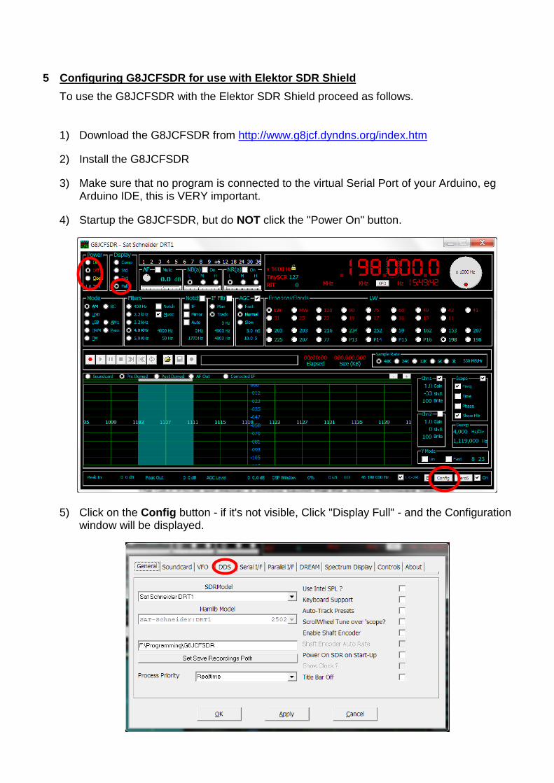
5 Configuring G8JCFSDR for use with Elektor SDR Shield
To use the G8JCFSDR with the Elektor SDR Shield proceed as follows.
1) Download the G8JCFSDR from http://www.g8jcf.dyndns.org/index.htm
2) Install the G8JCFSDR
3) Make sure that no program is connected to the virtual Serial Port of your Arduino, eg Arduino IDE, this is VERY important.
4) Startup the G8JCFSDR, but do NOT click the "Power On" button.
5) Click on the Config button - if it's not visible, Click "Display Full" - and the Configuration window will be displayed.
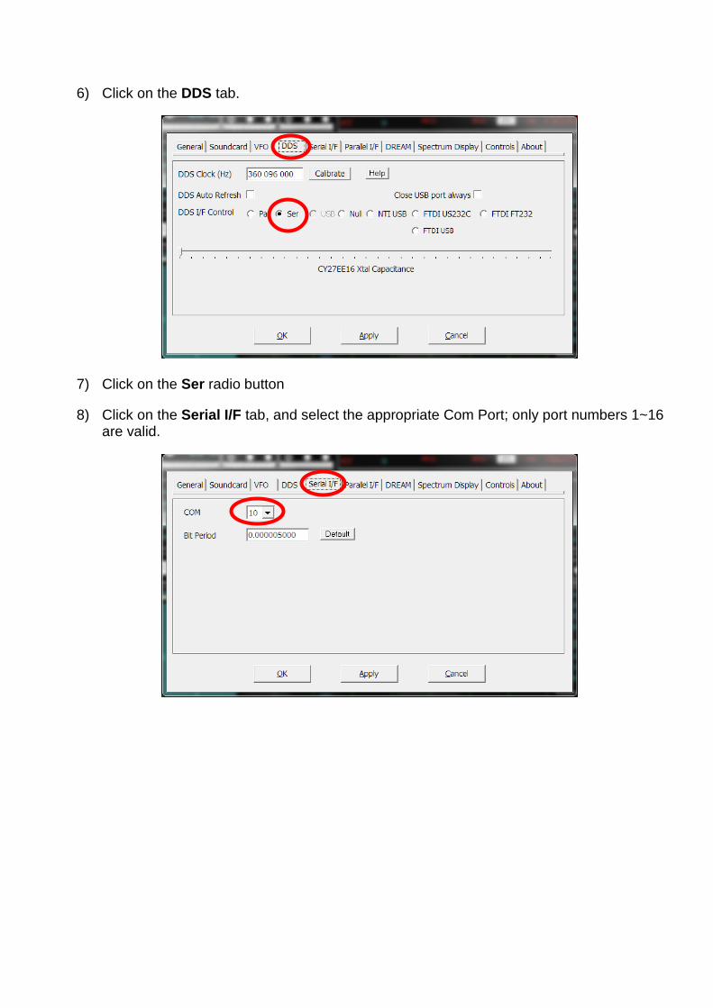
6) Click on the DDS tab.
7) Click on the Ser radio button
8) Click on the Serial I/F tab, and select the appropriate Com Port; only port numbers 1~16 are valid.
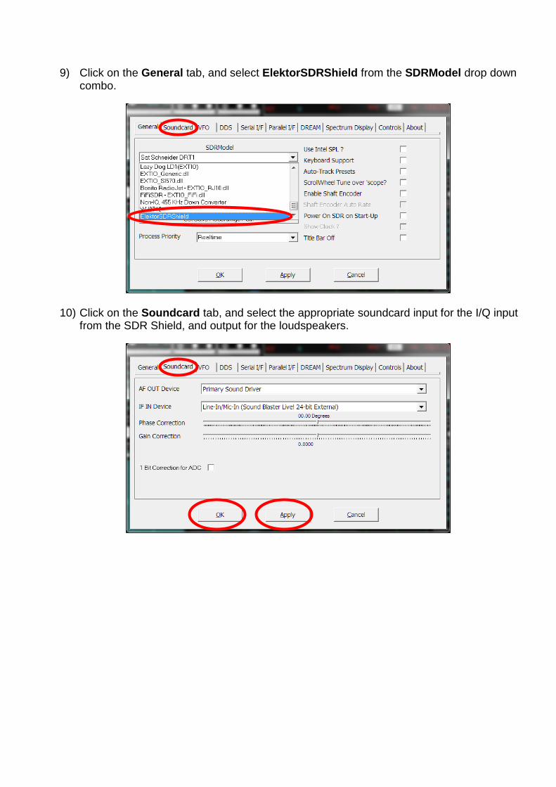
9) Click on the General tab, and select ElektorSDRShield from the SDRModel drop down combo.
10) Click on the Soundcard tab, and select the appropriate soundcard input for the I/Q input from the SDR Shield, and output for the loudspeakers.
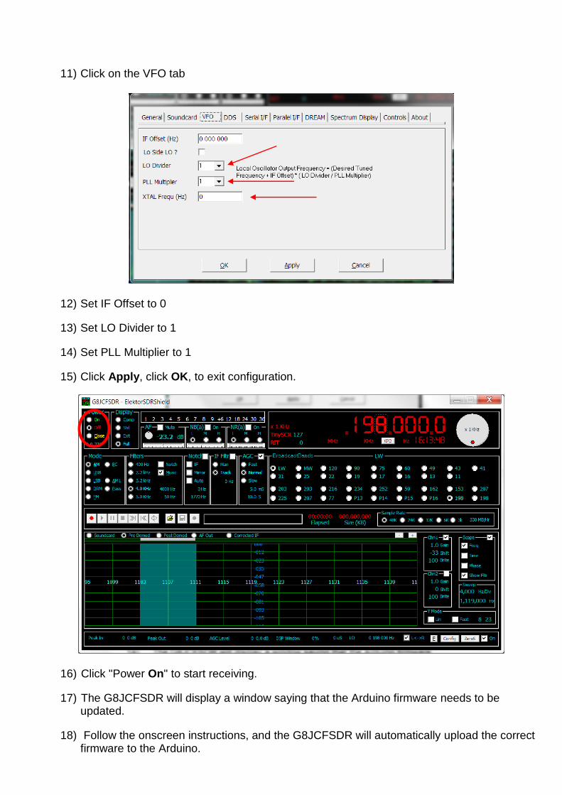
11) Click on the VFO tab
12) Set IF Offset to 0
13) Set LO Divider to 1
14) Set PLL Multiplier to 1
15) Click Apply, click OK, to exit configuration.
16) Click "Power On" to start receiving.
17) The G8JCFSDR will display a window saying that the Arduino firmware needs to be updated.
18) Follow the onscreen instructions, and the G8JCFSDR will automatically upload the correct firmware to the Arduino.
19) Once the firmware upload has been completed, the G8JCFSDR will start receiving.
20) Once you are happy that the G8JCFSDR is properly controlling the SDR Shield, you will probably want to perform a Calibration.
21) Tune to a known good frequency in the 10MHz range, see Radio Time Signal Stations
a. In Europe 9996 KHz is pretty good,
b. In North/South America 1000KHz,
c. In India 11000KHz.
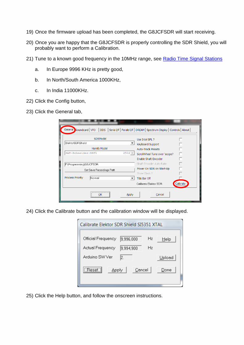
22) Click the Config button,
23) Click the General tab,
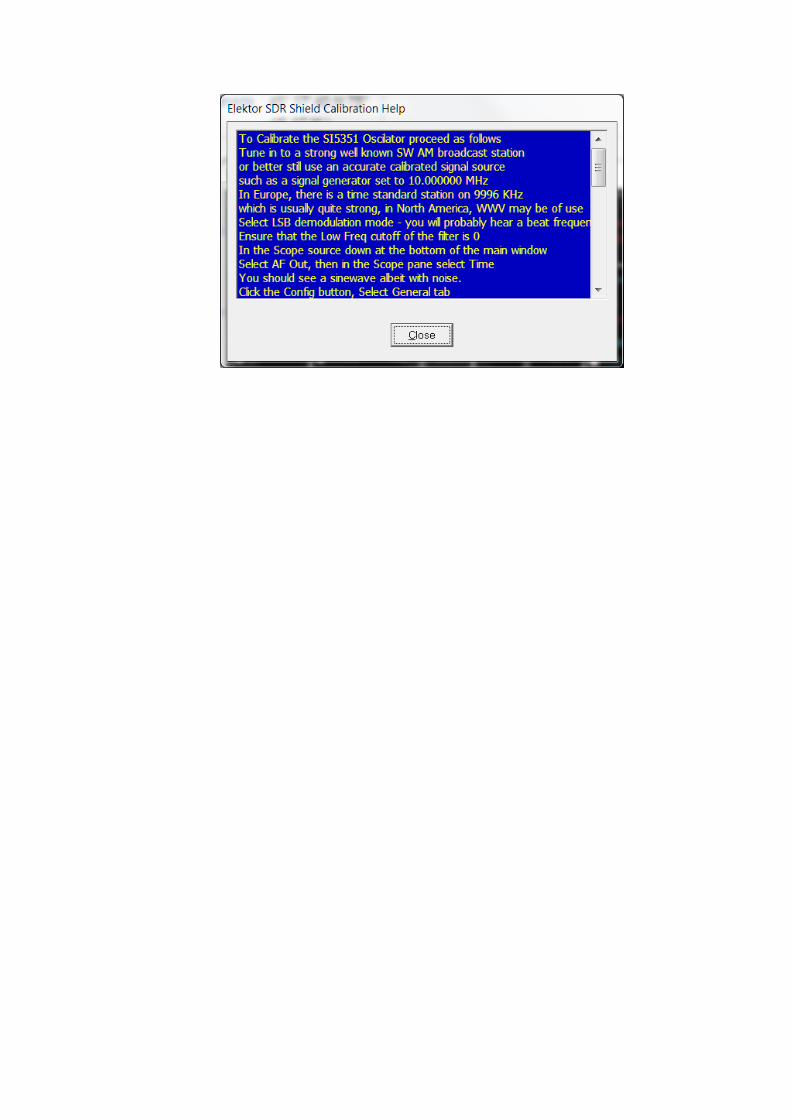
24) Click the Calibrate button and the calibration window will be displayed.
25) Click the Help button, and follow the onscreen instructions.
6 DRM - Digital Radio Mondiale
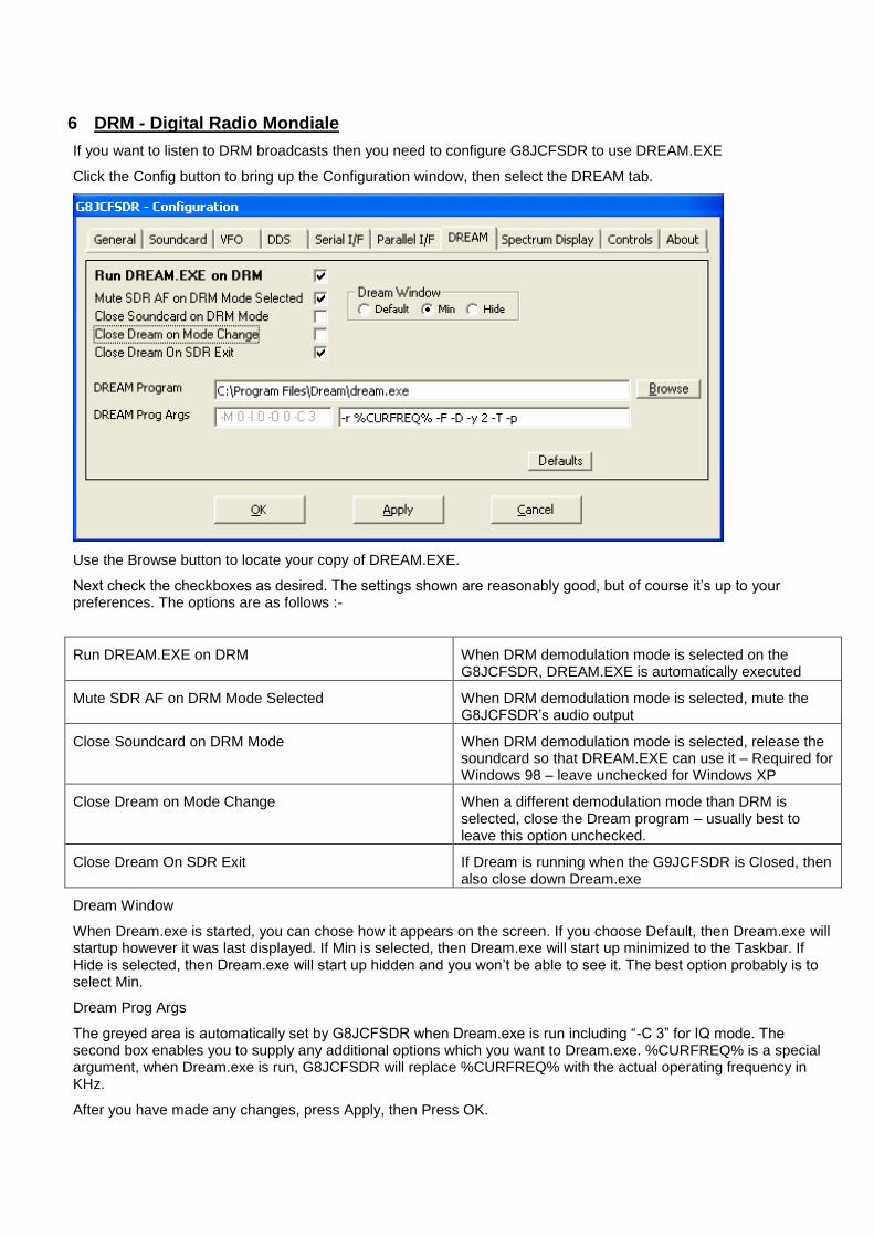
If you want to listen to DRM broadcasts then you need to configure G8JCFSDR to use DREAM.EXE
Click the Config button to bring up the Configuration window, then select the DREAM tab.
Use the Browse button to locate your copy of DREAM.EXE.
Next check the checkboxes as desired. The settings shown are reasonably good, but of course it’s up to your preferences. The options are as follows :-
Run DREAM.EXE on DRM When DRM demodulation mode is selected on the G8JCFSDR, DREAM.EXE is automatically executed
Mute SDR AF on DRM Mode Selected When DRM demodulation mode is selected, mute the G8JCFSDR’s audio output
Close Soundcard on DRM Mode When DRM demodulation mode is selected, release the soundcard so that DREAM.EXE can use it – Required for Windows 98 – leave unchecked for Windows XP
Close Dream on Mode Change When a different demodulation mode than DRM is selected, close the Dream program – usually best to leave this option unchecked.
Close Dream On SDR Exit If Dream is running when the G9JCFSDR is Closed, then also close down Dream.exe
Dream Window
When Dream.exe is started, you can chose how it appears on the screen. If you choose Default, then Dream.exe will startup however it was last displayed. If Min is selected, then Dream.exe will start up minimized to the Taskbar. If Hide is selected, then Dream.exe will start up hidden and you won’t be able to see it. The best option probably is to select Min.
Dream Prog Args
The greyed area is automatically set by G8JCFSDR when Dream.exe is run including “-C 3” for IQ mode. The second box enables you to supply any additional options which you want to Dream.exe. %CURFREQ% is a special argument, when Dream.exe is run, G8JCFSDR will replace %CURFREQ% with the actual operating frequency in KHz.
After you have made any changes, press Apply, then Press OK.