Embed Size (px)
Citation preview
GAINS D3.2 Airborne Validation Report
Deliverable ID: D3.2
Dissemination Level: PU
Project Acronym: GAINS
Grant: 783228 Call: H2020-SESAR-2016-2
Topic: SESAR-VLD1-09-2016 Solutions for General Aviation and Rotorcraft
Consortium Coordinator: HELIOS Edition Date: 01 November 2019 Edition: 00.00.00 Template Edition: 02.00.01
VERY LARGE-SCALE DEMONSTRATION
GAINS D3.2 AIRBORNE VALIDATION REPORT
2
Authoring & Approval
Authors of the document
Name/Beneficiary Position/Title Date
Dr. Marc Gerlach Work Package Leader 1 WP3 07/10/2019
Andreas Rossbach Work Package Leader 2 WP3 16/10/2019
Reviewers internal to the project
Name/Beneficiary Position/Title Date
Bob Darby/AOPA Work Package Leader WP4 15/10/2019
Andreia Simoes/HELIOS Project Manager 25/10/2018
Andy Davis/TRIG FS and LS 01/11/2019
Approved for submission to the SJU By - Representatives of beneficiaries involved in the project
Name/Beneficiary Position/Title Date
Philip Church/HELIOS SGA Coordinator 29/10/2019
Martin Robinson/AOPA FS and LS 29/10/2019
Santiago Soley/PILDO FS and LS 29/10/2019
Marc Gerlach/FAV EC 29/10/2019
Andy Davis/TRIG FS and LS 01/11/2019
Rejected By - Representatives of beneficiaries involved in the project
Name/Beneficiary Position/Title Date
Document History
Edition Date Status Author Justification
00.00.00 01/11/2019 Issued Dr. Marc Gerlach / Andreas Rossbach
Initial issue
Copyright Statement
This document and its content is an internal deliverable of the GAINS project and may not, except with the GAINS consortia express written permission, be distributed or have its content commercially exploited. This project has received funding from the SESAR Joint Undertaking under the European Union’s Horizon 2020 research and innovation programme under grant agreement No 783228. The opinions expressed herein reflect the author’s view only. Under no circumstances shall the SESAR Joint Undertaking be responsible for any use that may be made of the information contained herein.
GAINS D3.2 AIRBORNE VALIDATION REPORT
3
GAINS GENERAL AVIATION IMPROVED NAVIGATION AND SURVEILLANCE
The Airborne Equipment Validation Report is part of GAINS, a VLD project that has received funding from the SESAR Joint Undertaking under the grant agreement No 783228 under European Union’s Horizon 2020 research and innovation programme. This two-year project initiated in January 2018 is overseen by a consortium from the general aviation (GA) community: AOPA UK, Pildo Labs, Funke Avionics and Trig Avionics. Aviation consultancy Helios is the project coordinator.
Abstract
This document contains a description and validation of the airborne electronic conspicuity devices provided by f.u.n.k.e. AVIONICS that were used during the GAINS Surveillance demonstrations.
It summarizes the purpose of the PlaneSight devices and the experiences made during the GAINS demonstration project. Specific comments received concerning the operational use as well as general comments on the use of electronic conspicuity devices were validated against the PlaneSight design and functionality.
Other airborne equipment from other manufacturers used during the GAINS demonstrations is not covered in this report.
Some recommendations for a future PlaneSight unit as a consequence of this analysis are included.
.
GAINS D3.2 AIRBORNE VALIDATION REPORT
4
Table of Contents
Abstract ................................................................................................................................... 3
1 Executive summary .................................................................................................... 6
2 Introduction ............................................................................................................... 7
2.1 Scope ............................................................................................................................ 7
2.2 Intended readership ...................................................................................................... 7
2.3 Background ................................................................................................................... 7
2.4 Structure of the document ............................................................................................. 7
2.5 List of Acronyms ............................................................................................................ 8
3 Airborne ADS-B equipment description ....................................................................... 9
3.1 PlaneSight description ................................................................................................... 9
3.2 PlaneSight Limitations ................................................................................................. 12
3.3 PlaneSight Development Background ........................................................................... 12
3.4 PlaneSight Units for the GAINS demonstrations ............................................................ 13
3.5 Modifications and Enhancements ................................................................................ 14
4 Planesight in GAINS Demonstrations ........................................................................ 16
4.1 Flight trials with PlaneSight Units ................................................................................. 16
4.2 General Feedback on EC Devices .................................................................................. 16 4.2.1 Basic instructions and set-up .......................................................................................................... 16 4.2.2 Audio alerts and warnings ............................................................................................................... 16 4.2.3 Aircraft on the ground ..................................................................................................................... 17 4.2.4 Interoperability ............................................................................................................................... 17
5 PlaneSight Validation ............................................................................................... 18
5.1 Installation .................................................................................................................. 18
5.2 Antenna ...................................................................................................................... 18
5.3 Display ........................................................................................................................ 18
5.4 Warning tones ............................................................................................................. 18
5.5 Power Supply .............................................................................................................. 19
5.6 Settings ....................................................................................................................... 19
5.7 Detectability ................................................................................................................ 20
6 Conclusion ............................................................................................................... 21
7 References ............................................................................................................... 22
GAINS D3.2 AIRBORNE VALIDATION REPORT
5
List of Tables
Table 1 - List of acronyms ........................................................................................................................ 8
Table 2 – Demonstrations / Tests sites with PlaneSight units .............................................................. 16
List of Figures
Figure 1 - PlaneSight Front View ............................................................................................................. 9
Figure 2 - PlaneSight Block Diagram ...................................................................................................... 10
Figure 3 - PlaneSight Rear View............................................................................................................. 11
Figure 4 - PlaneSight with antennas ...................................................................................................... 11
Figure 5 - PlaneSight connected to XCSoar ........................................................................................... 12
Figure 6 - Preparation of PlaneSight Units for GAINS ........................................................................... 13
Figure 7 - AV-22 Antenna ..................................................................................................................... 14
Figure 8 - PlaneSight with AV-22 antenna ............................................................................................. 15
Figure 9 – PlaneSight installation examples .......................................................................................... 15
Figure 10 - Comparison Planesight with 20 Watts and 5 Watts transmit power .................................. 20
GAINS D3.2 AIRBORNE VALIDATION REPORT
6
1 Executive summary
The objectives of GAINS are to validate, through live flying demonstrations, concepts enabled by Global Navigation Satellite System (GNSS) and EGNOS. These include a Surveillance Concept proposing an electronic conspicuity solution and a Navigation Concept proposing instrument flight procedure elements to meet the needs of GA, including both fixed wing and rotorcraft. GAINS’s Surveillance and Navigation Demonstrations aim to show the wider aviation community how improvements being developed by SESAR can be adapted to the respective Concepts enhancing GA operations without prohibitive cost or certification requirements.
This report describes the purpose and functionality of the PlaneSight Unit, an electronic conspicuity device, as used in the project surveillance demonstrations.
Innovative electronic conspicuity devices are intended to make pilots aware of each other’s presence by transmitting and receiving ADS-B position information. The two-way exchange of data and traffic warnings shall enhance real-time traffic awareness and improve safety.
This report assesses the Design and functionality of the PlaneSight based on the surveillance demonstrations results, acknowledging that there are known limitations with this type of equipment, which were substantiated by pilot feedback during the GAINS demonstrations.
The GAINS demonstrations flights showed that EC devices such as PlaneSight and others contribute significantly to situational awareness, but have shortcomings with respect to their usability. Many of the comments concerned the way how to depict air traffic in various situations and the related audio alerts. Most of the perceived shortcomings can be overcome by a higher flexibility of EC devices to feed existing displays and a more flexible customization of alert settings.
CAP 1391 limits the transmission output power to 40 Watts. In the GAINS trials 5W and 20W PlaneSight versions were used to see if lower power may also lead to good results. The observed reception quality with the GAINS ground surveillance station during all demonstrations indicate that 5 Watts seems to be the lower limit for a satisfactory detection range.
GAINS D3.2 AIRBORNE VALIDATION REPORT
7
2 Introduction
2.1 Scope
This validation report summarizes the activities of FAV to provide portable airborne ADS-B equipment for the GAINS flight demonstrations. This equipment was intended for those participants who were using an aircraft in the demos which was not ADS-B equipped.
This report validates the comments received and gives a recommendation for the development of future electronic conspicuity devices.
2.2 Intended readership
The information in this document is intended for those readers who require a more detailed view of the airborne equipment used for the GAINS flight demonstrations.
2.3 Background
The majority of Air Transport airplanes are equipped with ADS-B capable systems; whereas General Aviation still has a relatively low degree of ADS-B equipage and many aircraft have transponders which do not transmit ADS-B signals. Electronic conspicuity devices such as PlaneSight are intended to close this gap or at least minimize it.
The GAINS project should demonstrate how low cost and low certification ADS-B equipment and airborne electronic conspicuity (EC) devices can be used in the cockpit of General Aviation aircraft to enhance traffic situation awareness. Another objective was the demonstration that the reception range of the ADS-B equipment is adequate for operation in the circuit and adjacent class G airspace.
GAINS concentrated on the aerodrome and near-aerodrome environment, where the risk of airborne conflict or collision is up to 8 times greater than in ‘open airspace’ (class G without a separation service).
To get enough participants with appropriate equipped aircraft for the demonstration flights, a sufficient number of easily installable ADS-B equipment was necessary. This was ensured by the provision of 25 PlaneSight units with its ADS-B transmit/receive capability together with its integrated Cockpit Display of Traffic Information (CDTI). The PlaneSight transmission element is compliant with CAP1391.
2.4 Structure of the document
The first part describes the ADS-B equipment provided by f.u.n.k.e. AVIONICS for the GAINS demonstrations, including some background information to the design and development of the PlaneSight units (§4).
The second part summarizes the comments and experiences made during the flight tests (§5).
The third part summarizes and evaluates the received feedback (§6).
GAINS D3.2 AIRBORNE VALIDATION REPORT
8
The report closes with a short conclusion (§7).
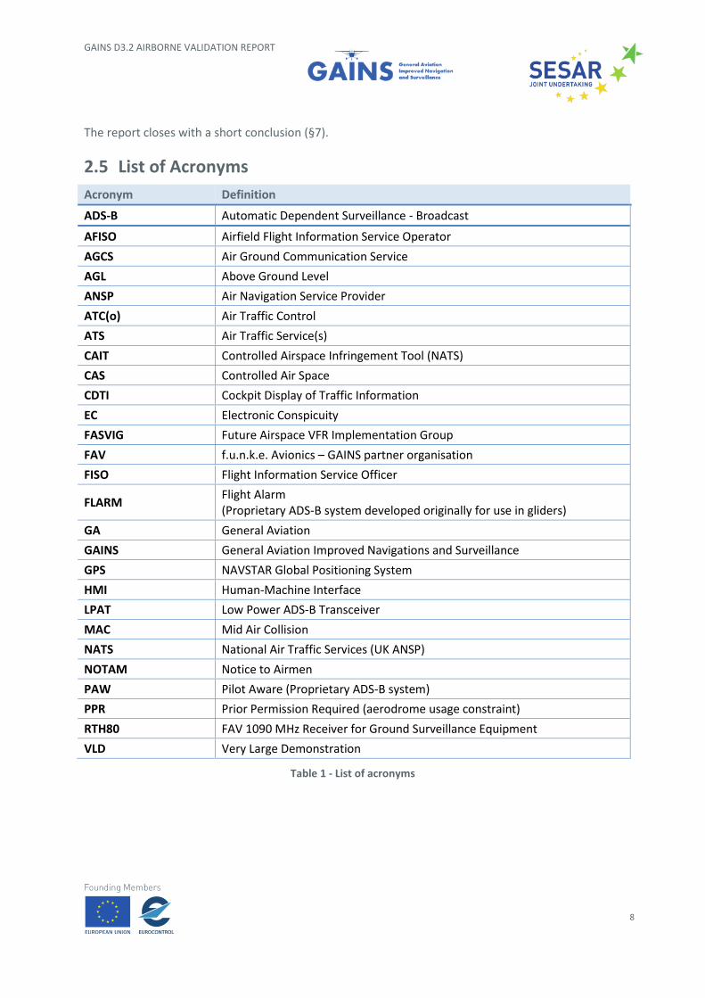
2.5 List of Acronyms
Acronym Definition
ADS-B Automatic Dependent Surveillance - Broadcast
AFISO Airfield Flight Information Service Operator
AGCS Air Ground Communication Service
AGL Above Ground Level
ANSP Air Navigation Service Provider
ATC(o) Air Traffic Control
ATS Air Traffic Service(s)
CAIT Controlled Airspace Infringement Tool (NATS)
CAS Controlled Air Space
CDTI Cockpit Display of Traffic Information
EC Electronic Conspicuity
FASVIG Future Airspace VFR Implementation Group
FAV f.u.n.k.e. Avionics – GAINS partner organisation
FISO Flight Information Service Officer
FLARM Flight Alarm (Proprietary ADS-B system developed originally for use in gliders)
GA General Aviation
GAINS General Aviation Improved Navigations and Surveillance
GPS NAVSTAR Global Positioning System
HMI Human-Machine Interface
LPAT Low Power ADS-B Transceiver
MAC Mid Air Collision
NATS National Air Traffic Services (UK ANSP)
NOTAM Notice to Airmen
PAW Pilot Aware (Proprietary ADS-B system)
PPR Prior Permission Required (aerodrome usage constraint)
RTH80 FAV 1090 MHz Receiver for Ground Surveillance Equipment
VLD Very Large Demonstration
Table 1 - List of acronyms
GAINS D3.2 AIRBORNE VALIDATION REPORT
9
3 Airborne ADS-B equipment description
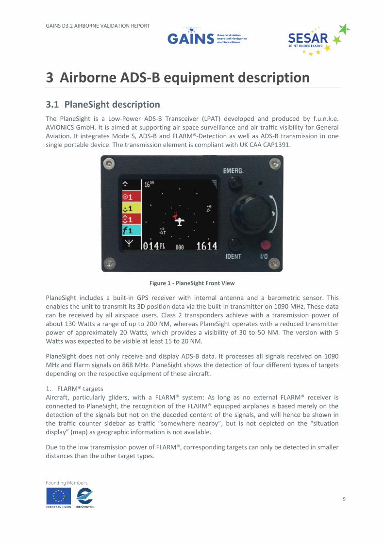
3.1 PlaneSight description
The PlaneSight is a Low-Power ADS-B Transceiver (LPAT) developed and produced by f.u.n.k.e. AVIONICS GmbH. It is aimed at supporting air space surveillance and air traffic visibility for General Aviation. It integrates Mode S, ADS-B and FLARM®-Detection as well as ADS-B transmission in one single portable device. The transmission element is compliant with UK CAA CAP1391.
Figure 1 - PlaneSight Front View
PlaneSight includes a built-in GPS receiver with internal antenna and a barometric sensor. This enables the unit to transmit its 3D position data via the built-in transmitter on 1090 MHz. These data can be received by all airspace users. Class 2 transponders achieve with a transmission power of about 130 Watts a range of up to 200 NM, whereas PlaneSight operates with a reduced transmitter power of approximately 20 Watts, which provides a visibility of 30 to 50 NM. The version with 5 Watts was expected to be visible at least 15 to 20 NM.
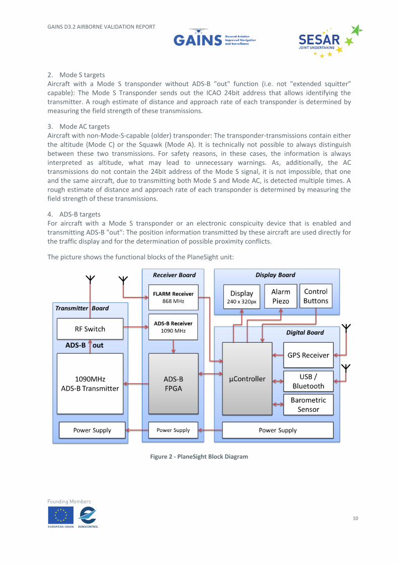
PlaneSight does not only receive and display ADS-B data. It processes all signals received on 1090 MHz and Flarm signals on 868 MHz. PlaneSight shows the detection of four different types of targets depending on the respective equipment of these aircraft.
1. FLARM® targets Aircraft, particularly gliders, with a FLARM® system: As long as no external FLARM® receiver is connected to PlaneSight, the recognition of the FLARM® equipped airplanes is based merely on the detection of the signals but not on the decoded content of the signals, and will hence be shown in the traffic counter sidebar as traffic “somewhere nearby”, but is not depicted on the “situation display” (map) as geographic information is not available.
Due to the low transmission power of FLARM®, corresponding targets can only be detected in smaller distances than the other target types.
GAINS D3.2 AIRBORNE VALIDATION REPORT
10
2. Mode S targets Aircraft with a Mode S transponder without ADS-B "out" function (i.e. not "extended squitter" capable): The Mode S Transponder sends out the ICAO 24bit address that allows identifying the transmitter. A rough estimate of distance and approach rate of each transponder is determined by measuring the field strength of these transmissions.
3. Mode AC targets Aircraft with non-Mode-S-capable (older) transponder: The transponder-transmissions contain either the altitude (Mode C) or the Squawk (Mode A). It is technically not possible to always distinguish between these two transmissions. For safety reasons, in these cases, the information is always interpreted as altitude, what may lead to unnecessary warnings. As, additionally, the AC transmissions do not contain the 24bit address of the Mode S signal, it is not impossible, that one and the same aircraft, due to transmitting both Mode S and Mode AC, is detected multiple times. A rough estimate of distance and approach rate of each transponder is determined by measuring the field strength of these transmissions.
4. ADS-B targets For aircraft with a Mode S transponder or an electronic conspicuity device that is enabled and transmitting ADS-B "out": The position information transmitted by these aircraft are used directly for the traffic display and for the determination of possible proximity conflicts.
The picture shows the functional blocks of the PlaneSight unit:
Figure 2 - PlaneSight Block Diagram
GAINS D3.2 AIRBORNE VALIDATION REPORT
11
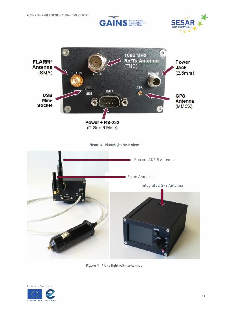
Figure 3 - PlaneSight Rear View
Figure 4 - PlaneSight with antennas
Integrated GPS Antenna
Procom ADS-B Antenna
Flarm Antenna
GAINS D3.2 AIRBORNE VALIDATION REPORT
12
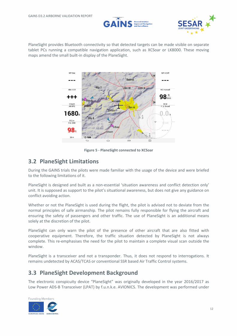
PlaneSight provides Bluetooth connectivity so that detected targets can be made visible on separate tablet PCs running a compatible navigation application, such as XCSoar or LK8000. These moving maps amend the small built-in display of the PlaneSight.
Figure 5 - PlaneSight connected to XCSoar
3.2 PlaneSight Limitations
During the GAINS trials the pilots were made familiar with the usage of the device and were briefed to the following limitations of it.
PlaneSight is designed and built as a non-essential ‘situation awareness and conflict detection only’ unit. It is supposed as support to the pilot’s situational awareness, but does not give any guidance on conflict avoiding action.
Whether or not the PlaneSight is used during the flight, the pilot is advised not to deviate from the normal principles of safe airmanship. The pilot remains fully responsible for flying the aircraft and ensuring the safety of passengers and other traffic. The use of PlaneSight is an additional means solely at the discretion of the pilot.
PlaneSight can only warn the pilot of the presence of other aircraft that are also fitted with cooperative equipment. Therefore, the traffic situation detected by PlaneSight is not always complete. This re-emphasises the need for the pilot to maintain a complete visual scan outside the window.
PlaneSight is a transceiver and not a transponder. Thus, it does not respond to interrogations. It remains undetected by ACAS/TCAS or conventional SSR based Air Traffic Control systems.
3.3 PlaneSight Development Background
The electronic conspicuity device “PlaneSight” was originally developed in the year 2016/2017 as Low Power ADS-B Transceiver (LPAT) by f.u.n.k.e. AVIONICS. The development was performed under
GAINS D3.2 AIRBORNE VALIDATION REPORT
13
a contract of U.K. National Air Traffic Services (NATS). The LPAT development was part of the project EVA – Electronic Visibility via ADS-B.
The EVA project aimed at enhancing flight safety by improving the visibility of general aviation pilots to each other and to air traffic control. LPAT in EVA was intended for pilots who were flying aircraft not equipped with a transponder and should provide minimum functionality for pilots to see and to be seen by other traffic. The unit was designed to be a light-weight carry-on device that is affordable, requires no special installation and is simple to use.
A purpose of the project EVA was to identify how the regulation and certification of electronic conspicuity (EC) devices can be minimised and to produce guidance material for European aviation standards, to speed up the availability of this smart traffic technology.
The EVA project was co-funded by SESAR Joint Undertaking.
The content and design of the LPAT display, the HMI and the menu settings were defined by NATS in the LPAT Specification Version 3.3 dated November 2016.
3.4 PlaneSight Units for the GAINS demonstrations
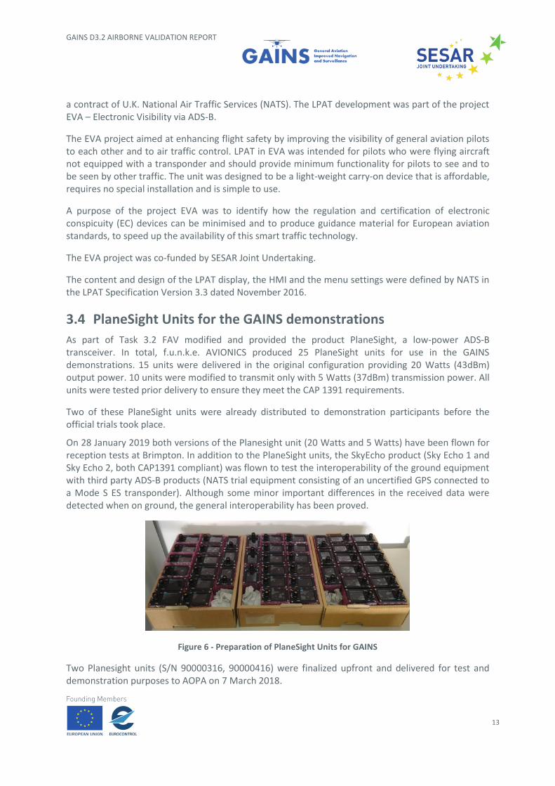
As part of Task 3.2 FAV modified and provided the product PlaneSight, a low-power ADS-B transceiver. In total, f.u.n.k.e. AVIONICS produced 25 PlaneSight units for use in the GAINS demonstrations. 15 units were delivered in the original configuration providing 20 Watts (43dBm) output power. 10 units were modified to transmit only with 5 Watts (37dBm) transmission power. All units were tested prior delivery to ensure they meet the CAP 1391 requirements.
Two of these PlaneSight units were already distributed to demonstration participants before the official trials took place.
On 28 January 2019 both versions of the Planesight unit (20 Watts and 5 Watts) have been flown for reception tests at Brimpton. In addition to the PlaneSight units, the SkyEcho product (Sky Echo 1 and Sky Echo 2, both CAP1391 compliant) was flown to test the interoperability of the ground equipment with third party ADS-B products (NATS trial equipment consisting of an uncertified GPS connected to a Mode S ES transponder). Although some minor important differences in the received data were detected when on ground, the general interoperability has been proved.
Figure 6 - Preparation of PlaneSight Units for GAINS
Two Planesight units (S/N 90000316, 90000416) were finalized upfront and delivered for test and demonstration purposes to AOPA on 7 March 2018.
GAINS D3.2 AIRBORNE VALIDATION REPORT
14
The rest of the units we were finalized and delivered on 11 July 2018. The shipment included:
• 13 x PlaneSight LPAT-(000)-(000) providing 20 Watts Tx out: Serial numbers: 90002416, 90002316, 90002116, 90002016, 90001816, 90001716, 90001616, 90001516, 90001416, 90001316, 90001216, 90000616, 90000516.
• 10 x PlaneSight LPAT-(000)-(100) providing 5 Watts Tx out: Serial numbers: 90002716, 90002816, 90002916, 90003016, 90003116, 90003216, 90003316, 90003416, 90003516, 90003616.
All units were delivered with following accessories:
• ADS-B Antenna Procom FLX 900/1090 (FME);
• 90° Adapter FME to TNC;
• Flarm Antenna (SMA);
• Power cable;
• Velcro pads.
3.5 Modifications and Enhancements
Bob Darby (AOPA), leader of GAINS WP4, Surveillance demonstrations, informed f.u.n.k.e. AVIONICS on 24 August 2018 by e-mail that he had difficulties when positioning the Planesight unit on the dashboard. The 1090MHz antenna touched the windshield and made a proper positioning difficult.
To overcome this problem, f.u.n.k.e. AVIONICS recommended to use an extension cable for the ADS--B antenna and to fix it in vertical position with a tape to the front side window or another appropriate location. f.u.n.k.e. AVIONICs searched out suitable extension cables with appropriate connectors and sent a set to AOPA.
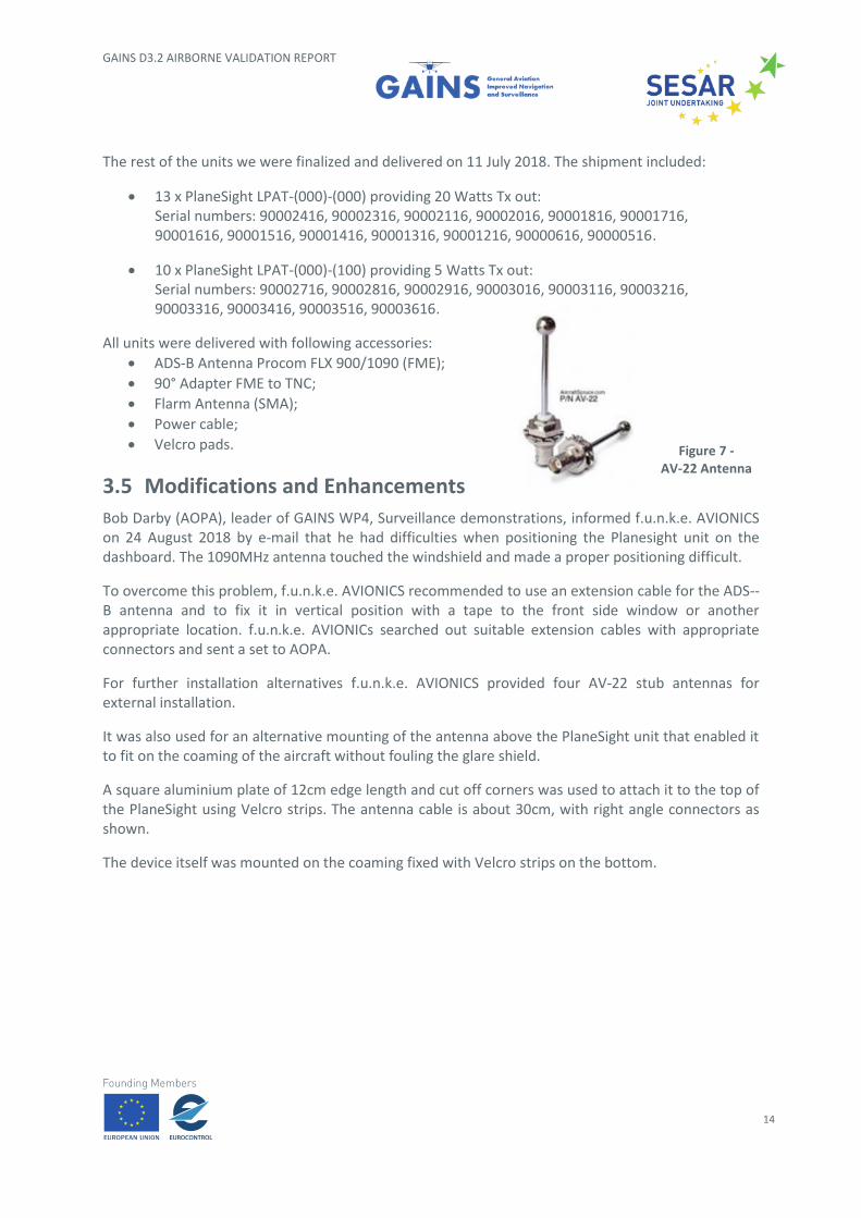
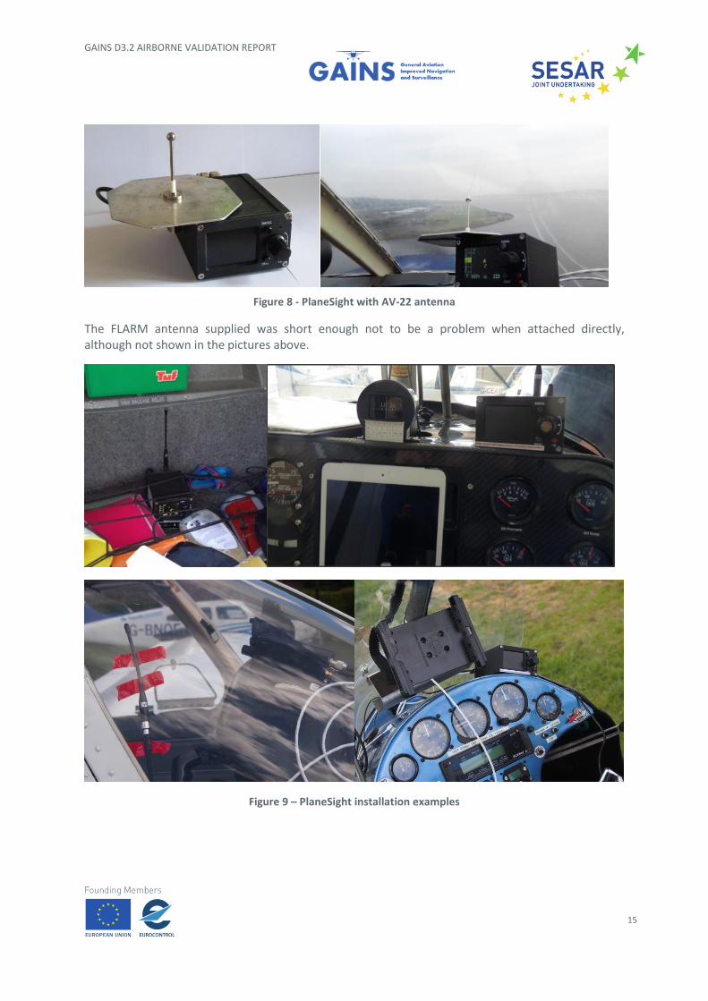
For further installation alternatives f.u.n.k.e. AVIONICS provided four AV-22 stub antennas for external installation.
It was also used for an alternative mounting of the antenna above the PlaneSight unit that enabled it to fit on the coaming of the aircraft without fouling the glare shield.
A square aluminium plate of 12cm edge length and cut off corners was used to attach it to the top of the PlaneSight using Velcro strips. The antenna cable is about 30cm, with right angle connectors as shown.
The device itself was mounted on the coaming fixed with Velcro strips on the bottom.
Figure 7 - AV-22 Antenna
GAINS D3.2 AIRBORNE VALIDATION REPORT
15
Figure 8 - PlaneSight with AV-22 antenna
The FLARM antenna supplied was short enough not to be a problem when attached directly, although not shown in the pictures above.
Figure 9 – PlaneSight installation examples
GAINS D3.2 AIRBORNE VALIDATION REPORT
16
4 Planesight in GAINS Demonstrations
4.1 Flight trials with PlaneSight Units
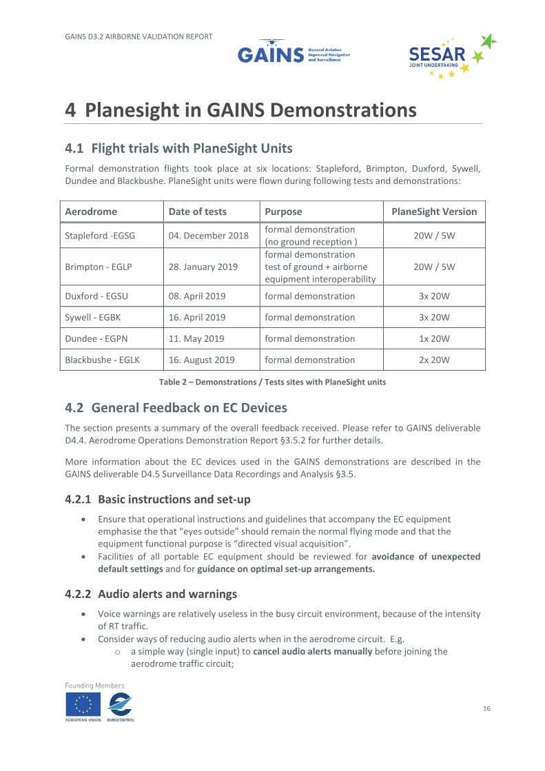
Formal demonstration flights took place at six locations: Stapleford, Brimpton, Duxford, Sywell, Dundee and Blackbushe. PlaneSight units were flown during following tests and demonstrations:
Table 2 – Demonstrations / Tests sites with PlaneSight units
4.2 General Feedback on EC Devices
The section presents a summary of the overall feedback received. Please refer to GAINS deliverable D4.4. Aerodrome Operations Demonstration Report §3.5.2 for further details.
More information about the EC devices used in the GAINS demonstrations are described in the GAINS deliverable D4.5 Surveillance Data Recordings and Analysis §3.5.
4.2.1 Basic instructions and set-up
• Ensure that operational instructions and guidelines that accompany the EC equipment emphasise the that “eyes outside” should remain the normal flying mode and that the equipment functional purpose is “directed visual acquisition”.
• Facilities of all portable EC equipment should be reviewed for avoidance of unexpected default settings and for guidance on optimal set-up arrangements.
4.2.2 Audio alerts and warnings
• Voice warnings are relatively useless in the busy circuit environment, because of the intensity of RT traffic.
• Consider ways of reducing audio alerts when in the aerodrome circuit. E.g. o a simple way (single input) to cancel audio alerts manually before joining the
aerodrome traffic circuit;
Aerodrome Date of tests Purpose PlaneSight Version
Stapleford -EGSG 04. December 2018 formal demonstration (no ground reception )
20W / 5W
Brimpton - EGLP 28. January 2019 formal demonstration test of ground + airborne equipment interoperability
20W / 5W
Duxford - EGSU 08. April 2019 formal demonstration 3x 20W
Sywell - EGBK 16. April 2019 formal demonstration 3x 20W
Dundee - EGPN 11. May 2019 formal demonstration 1x 20W
Blackbushe - EGLK 16. August 2019 formal demonstration 2x 20W
GAINS D3.2 AIRBORNE VALIDATION REPORT
17
o auto detection of being in an ATZ at circuit operational height to cause auto reduction of alerts, for example by adjustment of the alerting parameters.
4.2.3 Aircraft on the ground
• Inhibit transmission from aircraft on the ground, as it potentially can cause confusion and unnecessary alerts.
• An automatic mechanism to stop transmissions from a/c on the ground should be explored further by the EC equipment manufacturers. Almost no light GA aircraft have a “weight on wheels” sensor that can be used to suppress transmissions from a/c on the ground although this is common on commercial aircraft.
4.2.4 Interoperability
• Manufacturers should cooperate so that all GA cockpit EC equipment is fully interoperable. This is so that all a/c carrying EC equipment can receive and understand transmissions from all other GA EC devices and inform or alert the pilot as appropriate.
GAINS D3.2 AIRBORNE VALIDATION REPORT
18
5 PlaneSight Validation
5.1 Installation
The best place to position PlaneSight would be on the glare shield to have a heads-up view on the display and good access to the control knobs. The unit size and location of the antennas made it difficult or even impossible in some aircraft to fix the unit in such a position. As a consequence, the unit was placed at a significant worse place in some cases.
5.2 Antenna
The Procom antenna requires vertical positioning to provide good reception quality. The directly attached antenna collided in some cases with the windshield. Furthermore, an antenna position on the glare shield is not the best one as reception may be shaded by the cabin structure, the motor block or the pilots and/or passengers.
There were concerns having a cockpit mounted transmitter antenna. In the EVA project this issue was assessed and it was determined that with a distance of > 30 cm there are no health constraints ([E6.2.2]).
5.3 Display
The display was perceived by most pilots as being too small and too cluttered. Missing call sign information made it difficult to correlate seen traffic with the display ([4] Appendix E.3.2)
The display size was a trade-off between the overall unit size and a unit without any display. The PlaneSight unit has the capability to be connected to an external tablet via Bluetooth. The external display shows only the detected traffic but there is no graphical or acoustic warning on the external display.
NATS LPAT specification postulated an internal display for traffic awareness and device settings. The external display option was not used during the GAINS demonstration.
5.4 Warning tones
In a normal GA cockpit acoustic background, the audio tones generated by the Planesight were rated to be too quiet to attract attention. The warnings need to be fed to the pilot’s headset in some way. To avoid additional cables plane sight should be connected to a Bluetooth capable headset.
In dense airspace, especially during departure and approach, the kind and amount of warnings is critical. There were reports that too many warnings do not contribute to the situational awareness and are even perceived as distracting from radio communication. (see GAINS deliverable D4.5 Surveillance Data Recordings and Analysis § 3.5.2.1).
GAINS D3.2 AIRBORNE VALIDATION REPORT
19
PlaneSight generates beeps to warn the pilots of a potential conflict. The user can customize the acoustic warning behaviour with following settings:
• once: For each traffic object, an audio alert is triggered only once when it is recognized as a threat.
• repeat: The audio alert continues as long as the target poses a threat or the user confirms (and thus silences) the alarm with a knob push. Any alert needs to be confirmed separately. Depending on the threat level the audio alerts will be repeated every 4 seconds for the approach alarm, every 2 seconds for a potential collision threat and once per second for an active collision threat.
• Disabled: No audio alert is raised.
PlaneSight generates different sound schemes to specify the kind of threat in more detail:
• FLARM® short-short-short beep
• Mode S long-long beep
• Mode C long-short beep
• ADS-B long beep
The available variety of settings for audio alerts is obviously not sufficient to meet all personal preferences. The selection should include automatic filters and a specific behaviour when joining the aerodrome traffic circuit.
5.5 Power Supply
Initially, Planesight was planned as battery powered device. With the first tests during the PlaneSight development, this requirement was discarded. Battery operation turned out to be very unreliable. Problems were that the battery was empty or not fully charged and lacked sufficient battery capacity for longer flights as the PlaneSight power consumption is relatively high due to the active ADS-B transmission.
5.6 Settings
The settings menu was discussed and altered several times during the EVA project1. The default settings were defined by NATS during the EVA flight tests.
One setting which was altered was that the ADS-B transmission shall be deactivated when the PlaneSight Unit is switched on. At the beginning of the GAINS demonstrations the activation of ADS-B transmission was forgotten several times, although the action was included in the GAINS pre-flight checklist.
1 “PlaneSight” development was performed under a contract of U.K. National Air Traffic Services (NATS) as part of the project EVA – Electronic Visibility via ADS-B.
GAINS D3.2 AIRBORNE VALIDATION REPORT
20
This default setting should be reviewed. An auto-activation e.g. at a certain ground speed or altitude gain should be considered.
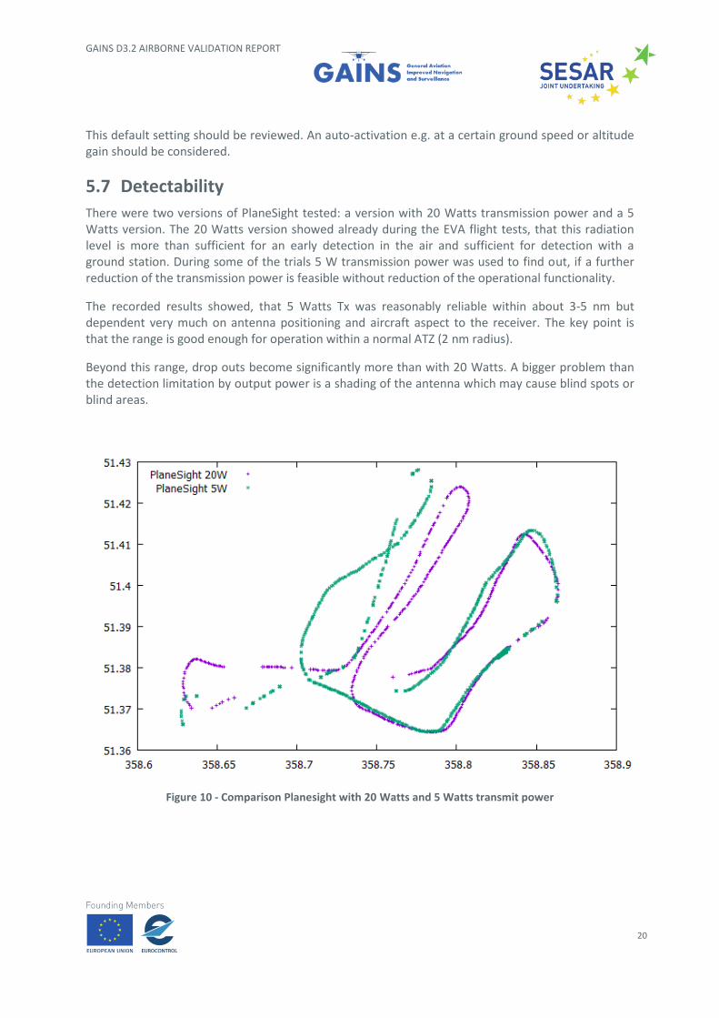
5.7 Detectability
There were two versions of PlaneSight tested: a version with 20 Watts transmission power and a 5 Watts version. The 20 Watts version showed already during the EVA flight tests, that this radiation level is more than sufficient for an early detection in the air and sufficient for detection with a ground station. During some of the trials 5 W transmission power was used to find out, if a further reduction of the transmission power is feasible without reduction of the operational functionality.
The recorded results showed, that 5 Watts Tx was reasonably reliable within about 3-5 nm but dependent very much on antenna positioning and aircraft aspect to the receiver. The key point is that the range is good enough for operation within a normal ATZ (2 nm radius).
Beyond this range, drop outs become significantly more than with 20 Watts. A bigger problem than the detection limitation by output power is a shading of the antenna which may cause blind spots or blind areas.
Figure 10 - Comparison Planesight with 20 Watts and 5 Watts transmit power
GAINS D3.2 AIRBORNE VALIDATION REPORT
21
6 Conclusion
The idea to have a portable, low-cost and easy-to-use electronic conspicuity device, which does not require great installation effort, is principally a good idea. But there are some massive constraints with this approach. Following points caused problems:
1. to find a position for the PlaneSight Unit which allows good view to the display without long head down time and good access to the operating elements.
2. to find a good antenna location without reception degradation.
The idea of an electronic conspicuity is definitely contributing to situational awareness and thus to an enhanced safety in General Aviation. This technology is certainly welcome when the appropriate equipment meets the usability requirements determined during the GAINS demonstrations.
Therefore, the PlaneSight successor model should have the following characteristics:
• Compact unit for fixed installation;
• Internal display not necessary if connected to an external moving map;
• Compatibility with existing displays connected by serial line, bus, BT, WLAN, ….;
• Possibility to use auto settings to reduce workload, e.g. reduction of GPS detection range at Low altitudes, automatic setting of height filters;
• Wide customization options for warning tones and warning thresholds;
GAINS D3.2 AIRBORNE VALIDATION REPORT
22
7 References
Reference Documents
[1] PlaneSight Operation Manual, Document No. 08.311.010.71e, Version 1.20 dated 28.05.2018.
[2] NATS LPAT Specification, Version 3.3, November 2016.
[3] GAINS D4.4 Aerodrome Operations Report, 31 October 2019.
[4] GAINS D4.5 Surveillance Data Recordings and Analysis, 31 October 2019.

GAINS D3.2 AIRBORNE VALIDATION REPORT
23