Embed Size (px)
Citation preview
This is an electronic reprint of the original article.This reprint may differ from the original in pagination and typographic detail.
Powered by TCPDF (www.tcpdf.org)
This material is protected by copyright and other intellectual property rights, and duplication or sale of all or part of any of the repository collections is not permitted, except that material may be duplicated by you for your research use or educational purposes in electronic or print form. You must obtain permission for any other use. Electronic or print copies may not be offered, whether for sale or otherwise to anyone who is not an authorised user.
Gallo, Pasquale; Hagiwara, Yohei; Shimada, Takahiro; Kitamura, TakayukiStrain energy density approach for brittle fracture from nano to macroscale and breakdown ofcontinuum theory
Published in:Theoretical and Applied Fracture Mechanics
DOI:10.1016/j.tafmec.2019.102300
Published: 04/07/2019
Document VersionPeer reviewed version
Published under the following license:CC BY-NC-ND
Please cite the original version:Gallo, P., Hagiwara, Y., Shimada, T., & Kitamura, T. (2019). Strain energy density approach for brittle fracturefrom nano to macroscale and breakdown of continuum theory. Theoretical and Applied Fracture Mechanics, 103,[102300]. https://doi.org/10.1016/j.tafmec.2019.102300

Strain energy density approach for brittle fracture from nano to macroscale and breakdown
of continuum theory
Pasquale Galloa,b *, Yohei Hagiwaraa, Takahiro Shimada a, Takayuki Kitamuraa
a Kyoto University, Department of Mechanical Engineering and Science, Kyoto-daigaku-Katsura, Nishikyo-Ku, Kyoto 615-8540, Japan b Aalto University, School of Engineering, Department of Applied Mechanics, P.O. Box 14300, FIN-00076 Aalto, 02150 Finland *Corresponding author: [email protected]
Abstract
In contrast to the great success at the macroscale, fracture mechanics theory fails to describe the
fracture at a critical size of several nanometers due to the emerging effect of atomic discreteness
with decreasing material size. Here, we propose a novel formulation for brittle fracture, from
macro- to even atomic scales, based on extended strain energy density, and give an insight into the
breakdown of continuum theory. Numerical experiments based on molecular statistics (MS)
simulations are conducted on single-edge cracked samples made of silicon while varying the size
until few nanometers, and loaded under mode I. The strain energy density is then defined as a
function of the interatomic potential and averaged over the fracture process zone. Finally, by using
an attenuation function, the atomic strain energy density gradient is homogenized to allow a
comparison between the continuum and discrete formulation. Results show that the fracture process
zone is scale independent, confirming that the ideal brittle fracture is ultimately governed by atomic
bond-breaking. A singular stress field according to continuum fracture mechanics is still also
present. However, when the singular stress field length (distance from the crack tip at which the
stress deviates 5% from the theoretical field of r0.5) is in the range of 4-5 times the fracture process
zone, continuum fracture mechanics fails to describe the fracture, i.e., the breakdown of continuum
theory. The new formulation, instead, goes well beyond that limit.
Keywords: atomistic simulation; multiscale; fracture mechanics; silicon; discrete fracture nanomechanics; strain energy density; nanoscale; brittle;
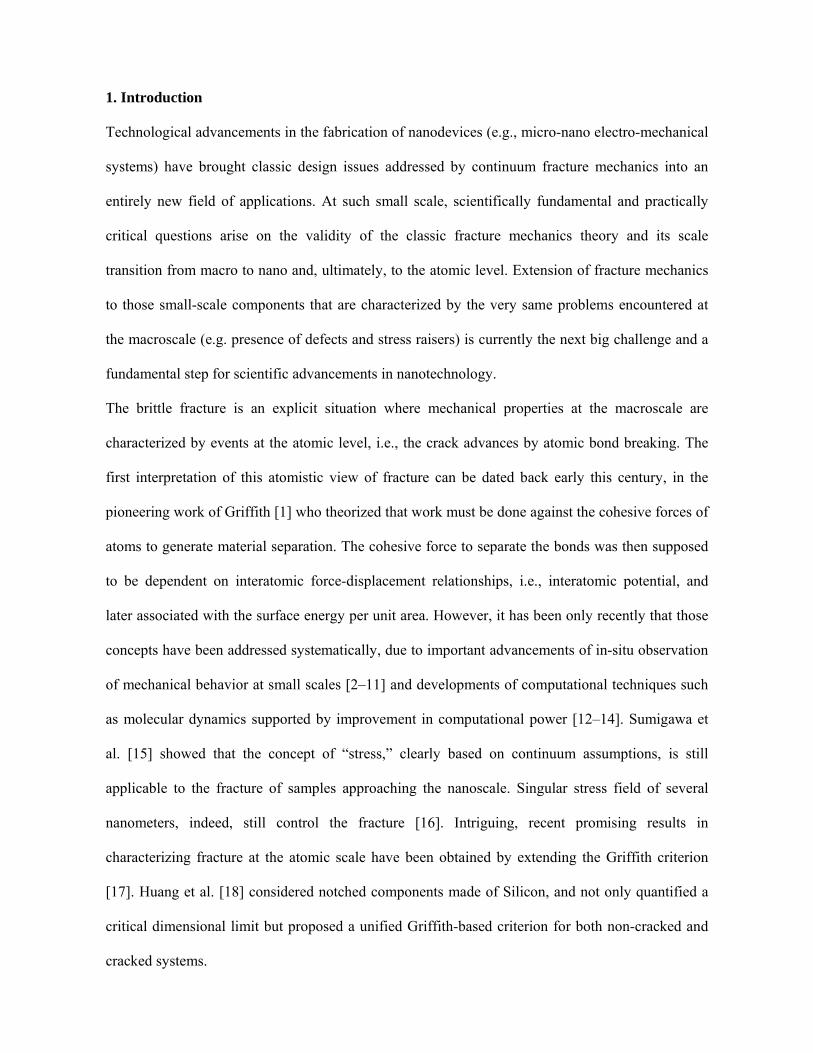
1. Introduction
Technological advancements in the fabrication of nanodevices (e.g., micro-nano electro-mechanical
systems) have brought classic design issues addressed by continuum fracture mechanics into an
entirely new field of applications. At such small scale, scientifically fundamental and practically
critical questions arise on the validity of the classic fracture mechanics theory and its scale
transition from macro to nano and, ultimately, to the atomic level. Extension of fracture mechanics
to those small-scale components that are characterized by the very same problems encountered at
the macroscale (e.g. presence of defects and stress raisers) is currently the next big challenge and a
fundamental step for scientific advancements in nanotechnology.
The brittle fracture is an explicit situation where mechanical properties at the macroscale are
characterized by events at the atomic level, i.e., the crack advances by atomic bond breaking. The
first interpretation of this atomistic view of fracture can be dated back early this century, in the
pioneering work of Griffith [1] who theorized that work must be done against the cohesive forces of
atoms to generate material separation. The cohesive force to separate the bonds was then supposed
to be dependent on interatomic force-displacement relationships, i.e., interatomic potential, and
later associated with the surface energy per unit area. However, it has been only recently that those
concepts have been addressed systematically, due to important advancements of in-situ observation
of mechanical behavior at small scales [2–11] and developments of computational techniques such
as molecular dynamics supported by improvement in computational power [12–14]. Sumigawa et
al. [15] showed that the concept of “stress,” clearly based on continuum assumptions, is still
applicable to the fracture of samples approaching the nanoscale. Singular stress field of several
nanometers, indeed, still control the fracture [16]. Intriguing, recent promising results in
characterizing fracture at the atomic scale have been obtained by extending the Griffith criterion
[17]. Huang et al. [18] considered notched components made of Silicon, and not only quantified a
critical dimensional limit but proposed a unified Griffith-based criterion for both non-cracked and
cracked systems.
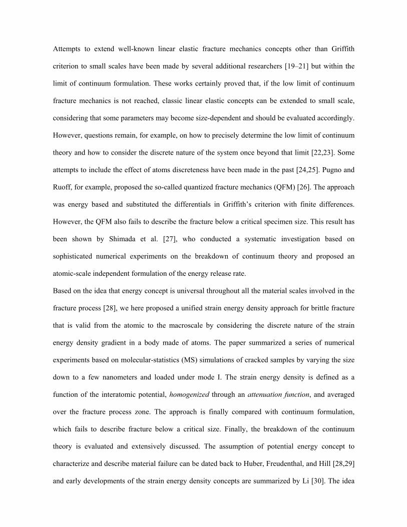
Attempts to extend well-known linear elastic fracture mechanics concepts other than Griffith
criterion to small scales have been made by several additional researchers [19–21] but within the
limit of continuum formulation. These works certainly proved that, if the low limit of continuum
fracture mechanics is not reached, classic linear elastic concepts can be extended to small scale,
considering that some parameters may become size-dependent and should be evaluated accordingly.
However, questions remain, for example, on how to precisely determine the low limit of continuum
theory and how to consider the discrete nature of the system once beyond that limit [22,23]. Some
attempts to include the effect of atoms discreteness have been made in the past [24,25]. Pugno and
Ruoff, for example, proposed the so-called quantized fracture mechanics (QFM) [26]. The approach
was energy based and substituted the differentials in Griffith’s criterion with finite differences.
However, the QFM also fails to describe the fracture below a critical specimen size. This result has
been shown by Shimada et al. [27], who conducted a systematic investigation based on
sophisticated numerical experiments on the breakdown of continuum theory and proposed an
atomic-scale independent formulation of the energy release rate.
Based on the idea that energy concept is universal throughout all the material scales involved in the
fracture process [28], we here proposed a unified strain energy density approach for brittle fracture
that is valid from the atomic to the macroscale by considering the discrete nature of the strain
energy density gradient in a body made of atoms. The paper summarized a series of numerical
experiments based on molecular-statistics (MS) simulations of cracked samples by varying the size
down to a few nanometers and loaded under mode I. The strain energy density is defined as a
function of the interatomic potential, homogenized through an attenuation function, and averaged
over the fracture process zone. The approach is finally compared with continuum formulation,
which fails to describe fracture below a critical size. Finally, the breakdown of the continuum
theory is evaluated and extensively discussed. The assumption of potential energy concept to
characterize and describe material failure can be dated back to Huber, Freudenthal, and Hill [28,29]
and early developments of the strain energy density concepts are summarized by Li [30]. The idea
to average the SED over a given control volume, instead, is mainly due to Lazzarin and co-workers
[31–33]. Averaged strain energy density concept has been proved to be very flexible at the
macroscale, and able to characterize static and fatigue behaviour of components under different
loading conditions and with different geometrical features. Its extension in the frame of a discrete
fracture mechanics theory would surely provide numerous advantages.
2. Method
2.1 Molecular statistics simulations, geometries, and mechanical properties
The fracture tests are conducted on nanoscale single-edge cracked specimens of brittle material in
silico using molecular statistics (MS) simulations performed by using the open-source code
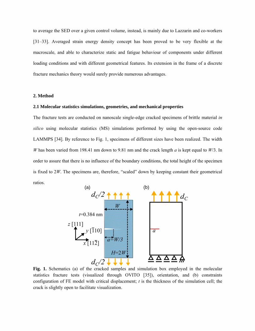
LAMMPS [34]. By reference to Fig. 1, specimens of different sizes have been realized. The width
W has been varied from 198.41 nm down to 9.81 nm and the crack length a is kept equal to W/3. In
order to assure that there is no influence of the boundary conditions, the total height of the specimen
is fixed to 2W. The specimens are, therefore, “scaled” down by keeping constant their geometrical
ratios.
Fig. 1. Schematics (a) of the cracked samples and simulation box employed in the molecular statistics fracture tests (visualized through OVITO [35]), orientation, and (b) constraints configuration of FE model with critical displacement; t is the thickness of the simulation cell; the crack is slightly open to facilitate visualization.
(a) (b)
The well-known modified Stillinger-Weber (SW) interatomic potential [36–38], widely used in the
investigation of ideal brittle fracture in silico, is employed in the simulations. The samples have,
therefore, the face-centered diamond-cubic structure of single crystal silicon and are oriented as
depicted in Fig. 1a. The crack plane coincides with the cleavage plane (111), and it is perpendicular
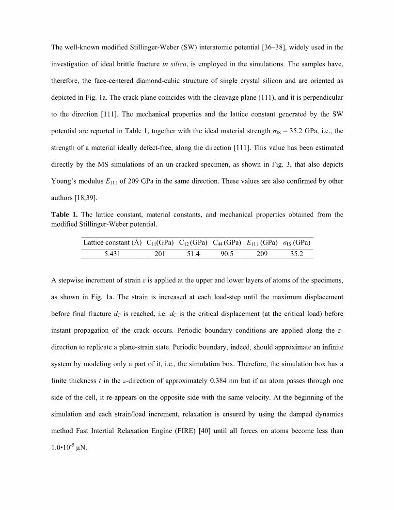
to the direction [111]. The mechanical properties and the lattice constant generated by the SW
potential are reported in Table 1, together with the ideal material strength σIS = 35.2 GPa, i.e., the
strength of a material ideally defect-free, along the direction [111]. This value has been estimated
directly by the MS simulations of an un-cracked specimen, as shown in Fig. 3, that also depicts
Young’s modulus E111 of 209 GPa in the same direction. These values are also confirmed by other
authors [18,39].
Table 1. The lattice constant, material constants, and mechanical properties obtained from the modified Stillinger-Weber potential.
Lattice constant (Å) C11(GPa) C12 (GPa) C44 (GPa) E111 (GPa) σIS (GPa)
5.431 201 51.4 90.5 209 35.2
A stepwise increment of strain ε is applied at the upper and lower layers of atoms of the specimens,
as shown in Fig. 1a. The strain is increased at each load-step until the maximum displacement
before final fracture dC is reached, i.e. dC is the critical displacement (at the critical load) before
instant propagation of the crack occurs. Periodic boundary conditions are applied along the z-
direction to replicate a plane-strain state. Periodic boundary, indeed, should approximate an infinite
system by modeling only a part of it, i.e., the simulation box. Therefore, the simulation box has a
finite thickness t in the z-direction of approximately 0.384 nm but if an atom passes through one
side of the cell, it re-appears on the opposite side with the same velocity. At the beginning of the
simulation and each strain/load increment, relaxation is ensured by using the damped dynamics
method Fast Intertial Relaxation Engine (FIRE) [40] until all forces on atoms become less than
1.0•10-5 µN.
The creation of a traction-free crack is realized by the so-called screening method: interactions
between atoms on pre-crack surfaces are artificially deleted. Creation of traction free atomically
sharp cracks can be somehow problematic when dealing with atomic systems because of the long-
range interaction between atoms. A detailed discussion of crack modeling is out of the scope of the
current work, but these problems and possible solutions are addressed by Andric et al. [13].
2.2 Finite Element Analyses
The fracture tests briefly introduced in section 2.1 are re-analyzed through Finite Element analyses.
Single-edge cracked samples were modeled by using the Ansys APDL 15.0 finite element software
package. A 2D 8-node element-type PLANE183 [41] and plane strain conditions were assumed. For
further accuracy, “concentration keypoint” was assumed to model the crack tip [41], and an
accurate mesh was realized, with elements close to the crack tip approximately smaller than a/105.
The concentration keypoint defines a point about which an area mesh will be skewed, and it is
particularly useful for modeling stress concentrations and crack tips. The liner elastic anisotropic
material model was selected. The stiffness matrix is derived from the three material constants of
Table 1, i.e., C11=201 GPa, C12=51.4 GPa, C44=90.5 GPa, for an orientation identical to that of
atomistic simulations (see Fig. 1). The constraints configuration of the model is shown in Fig. 1b.
Critical displacement dC (maximum displacement at critical load, before crack propagation)
obtained from MS simulations is then applied in order to evaluate stresses and other quantities at
the critical condition under continuum mechanics theory.
3. Formulation of the discrete averaged strain energy density
The formulation of the discrete averaged strain energy density approach aSEDDFM is a direct
extension of the well-known averaged SED approach proposed in the past by Lazzarin and co-
workers [31–33,42] at the macroscale. The approach reformulated here assumes that failure occurs
when the strain energy density averaged over a given control volume reaches a critical value WC,
and it is based on three key steps:
The definition of the critical strain energy density at failure, WC;
The assumption of the control volume/area over which the discrete strain energy density is
averaged;
The definition of strain energy density as a function of the interatomic potential (discrete
formulation).
Elastic deformations at the macroscopic level can be considered as a mutual behavior of atomic
displacements from their equilibrium positions. This definition is particularly true for ideal brittle
materials, (e.g., Silicon), where the atomic bond breaking governs the fracture, regardless of the
specimen size [19,20,25]. Therefore, it is reasonable to assume that the discrete critical strain
energy density has a similar formulation of its macroscale/continuum counterpart [43], provided
that the correct mechanical properties are employed. This assumption is particularly convenient in
the case of the SW potential used in the present study. The material behavior is indeed orthotropic,
defined by the three material constants reported in Table 1 or, eventually, by an equivalent isotropic
behavior for in-plane loadings. For these reasons, the critical strain energy density at failure WC of
the samples under considerations in the present paper, under mode I loading, is a direct extension of
the critical SED as derived in [31,33,43] for macroscale isotropic continuum component, and
reduces to the following form:
2IS
C1112
WE
, (1)
where σIS is the ideal material strength, E111 is Young’s modulus along the direction [111]. Both
quantities are derived from MS simulation of an un-cracked sample (see Table 1 or Fig. 3 of the
results, section 4.1).
RFPZ
VFPZ
2δ=0
VFPZ
RFPZ
r θ
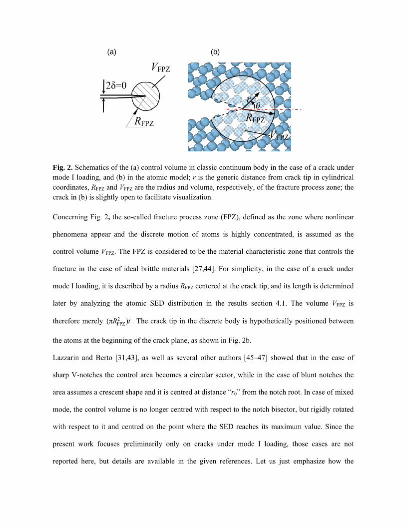
Fig. 2. Schematics of the (a) control volume in classic continuum body in the case of a crack under mode I loading, and (b) in the atomic model; r is the generic distance from crack tip in cylindrical coordinates, RFPZ and VFPZ are the radius and volume, respectively, of the fracture process zone; the crack in (b) is slightly open to facilitate visualization. Concerning Fig. 2, the so-called fracture process zone (FPZ), defined as the zone where nonlinear
phenomena appear and the discrete motion of atoms is highly concentrated, is assumed as the
control volume VFPZ. The FPZ is considered to be the material characteristic zone that controls the
fracture in the case of ideal brittle materials [27,44]. For simplicity, in the case of a crack under
mode I loading, it is described by a radius RFPZ centered at the crack tip, and its length is determined
later by analyzing the atomic SED distribution in the results section 4.1. The volume VFPZ is
therefore merely 2FPZ(π )R t . The crack tip in the discrete body is hypothetically positioned between
the atoms at the beginning of the crack plane, as shown in Fig. 2b.
Lazzarin and Berto [31,43], as well as several other authors [45–47] showed that in the case of
sharp V-notches the control area becomes a circular sector, while in the case of blunt notches the
area assumes a crescent shape and it is centred at distance “r0” from the notch root. In case of mixed
mode, the control volume is no longer centred with respect to the notch bisector, but rigidly rotated
with respect to it and centred on the point where the SED reaches its maximum value. Since the
present work focuses preliminarily only on cracks under mode I loading, those cases are not
reported here, but details are available in the given references. Let us just emphasize how the
(a) (b)
literature on the aSED is vast, and demonstrates the flexibility of the method in assessing both static
and fatigue behaviour of components of different geometries and loading conditions.
The discrete formulation of the averaged strain energy density aSEDDFM is evaluated as the sum of
the SED of all the atoms included in the FPZ divided by VFPZ:
ATOM
FPZDFM
FPZ
SEDaSED V
V
. (2)
For a given generic atom i at a distance r from the crack tip, its SEDATOM i is defined as the
difference between the atomic potential energy at the critical displacement dC and the unloaded
condition, multiplied by an attenuation function α(ri) [48], as follows:
ATOM ATOM C ATOM SED ( ) ( ) α( ) α( )i i ii i id o r r (3)
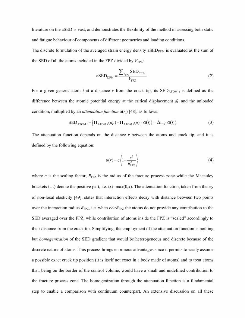
The attenuation function depends on the distance r between the atoms and crack tip, and it is
defined by the following equation:
2
2
2FPZ
α( ) 1 rr cR
(4)
where c is the scaling factor, RFPZ is the radius of the fracture process zone while the Macauley
brackets … denote the positive part, i.e. x=max(0,x). The attenuation function, taken from theory
of non-local elasticity [49], states that interaction effects decay with distance between two points
over the interaction radius RFPZ, i.e. when r>>RFPZ the atoms do not provide any contribution to the
SED averaged over the FPZ, while contribution of atoms inside the FPZ is “scaled” accordingly to
their distance from the crack tip. Simplifying, the employment of the attenuation function is nothing
but homogenization of the SED gradient that would be heterogeneous and discrete because of the
discrete nature of atoms. This process brings enormous advantages since it permits to easily assume
a possible exact crack tip position (it is itself not exact in a body made of atoms) and to treat atoms
that, being on the border of the control volume, would have a small and undefined contribution to
the fracture process zone. The homogenization through the attenuation function is a fundamental
step to enable a comparison with continuum counterpart. An extensive discussion on all these
aspects, needs and implications of using the attenuation function is presented in the Supplementary
Material S.2. Lastly, the scaling factor c is here determined by equating the aSEDDFM and WC, i.e.:
22
ATOM C ATOM 2FPZ
FPZC
( ) ( ) 1 ii i
FPZVr
d oR
cW V
(5)
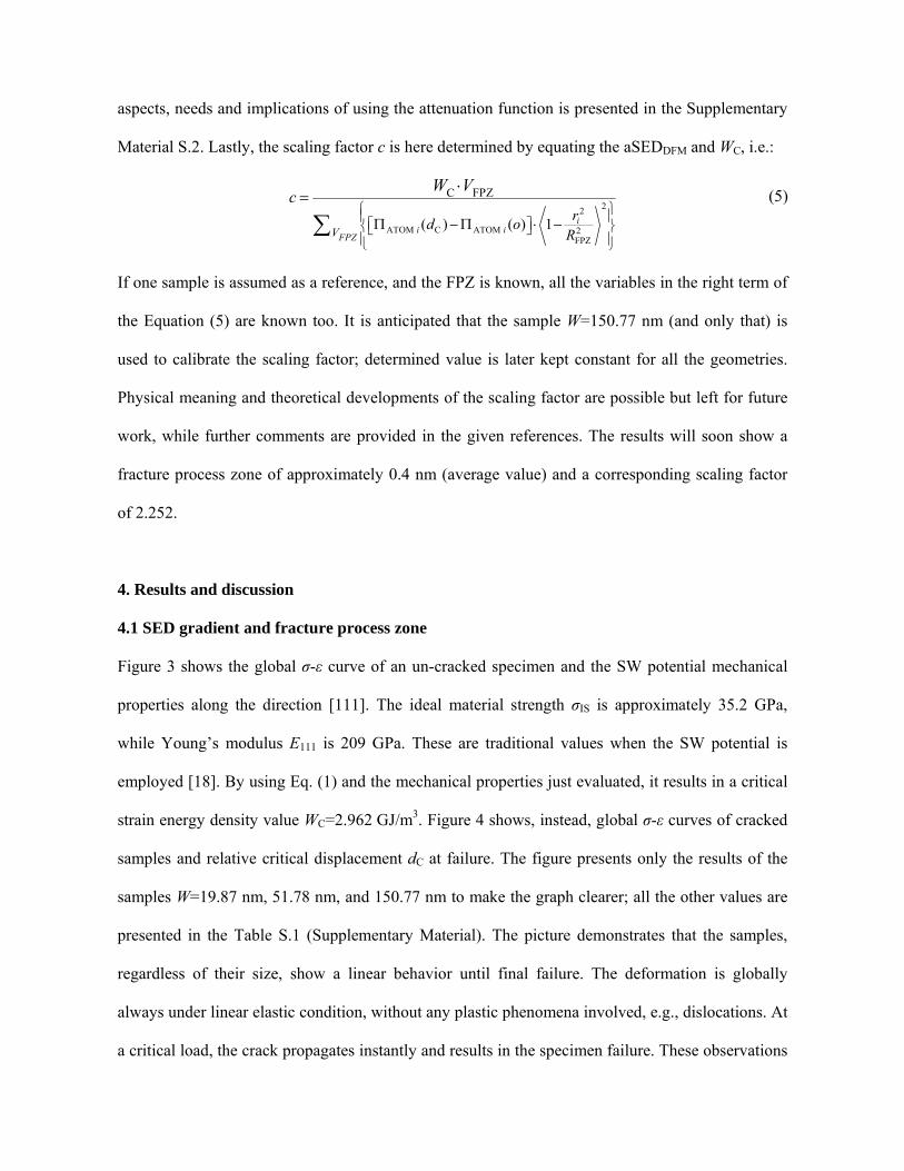
If one sample is assumed as a reference, and the FPZ is known, all the variables in the right term of
the Equation (5) are known too. It is anticipated that the sample W=150.77 nm (and only that) is
used to calibrate the scaling factor; determined value is later kept constant for all the geometries.
Physical meaning and theoretical developments of the scaling factor are possible but left for future
work, while further comments are provided in the given references. The results will soon show a
fracture process zone of approximately 0.4 nm (average value) and a corresponding scaling factor
of 2.252.
4. Results and discussion
4.1 SED gradient and fracture process zone
Figure 3 shows the global σ-ε curve of an un-cracked specimen and the SW potential mechanical
properties along the direction [111]. The ideal material strength σIS is approximately 35.2 GPa,
while Young’s modulus E111 is 209 GPa. These are traditional values when the SW potential is
employed [18]. By using Eq. (1) and the mechanical properties just evaluated, it results in a critical
strain energy density value WC=2.962 GJ/m3. Figure 4 shows, instead, global σ-ε curves of cracked
samples and relative critical displacement dC at failure. The figure presents only the results of the
samples W=19.87 nm, 51.78 nm, and 150.77 nm to make the graph clearer; all the other values are
presented in the Table S.1 (Supplementary Material). The picture demonstrates that the samples,
regardless of their size, show a linear behavior until final failure. The deformation is globally
always under linear elastic condition, without any plastic phenomena involved, e.g., dislocations. At
a critical load, the crack propagates instantly and results in the specimen failure. These observations
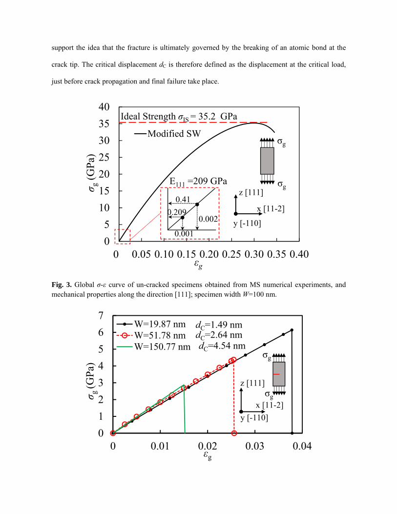
support the idea that the fracture is ultimately governed by the breaking of an atomic bond at the
crack tip. The critical displacement dC is therefore defined as the displacement at the critical load,
just before crack propagation and final failure take place.
Fig. 3. Global σ-ε curve of un-cracked specimens obtained from MS numerical experiments, and mechanical properties along the direction [111]; specimen width W=100 nm.
0
5
10
15
20
25
30
35
40
0.00 0.05 0.10 0.15 0.20 0.25 0.30 0.35 0.40
σ g(G
Pa)
εg
Modified SW
Ideal Strength σIS = 35.2 GPa
σg
σgz [111]
x [11-2]
0
0.002
0.41
0.001
0.209
E111 =209 GPa
y [-110]
0
1
2
3
4
5
6
7
0 0.01 0.02 0.03 0.04
σ g (G
Pa)
εg
W=19.87 nmW=51.78 nmW=150.77 nm
σg
σg
dC=1.49 nmdC=2.64 nmdC=4.54 nm
z [111]
y [-110]
x [11-2]
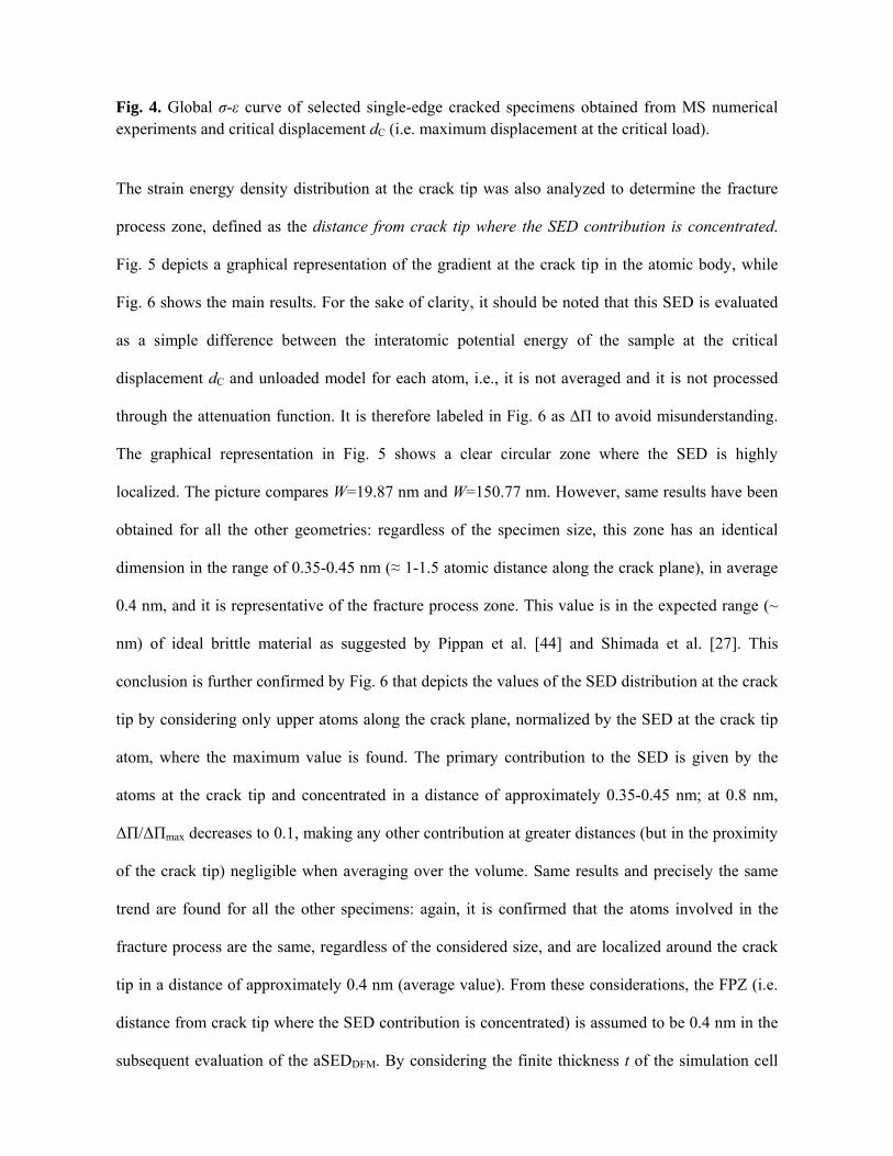
Fig. 4. Global σ-ε curve of selected single-edge cracked specimens obtained from MS numerical experiments and critical displacement dC (i.e. maximum displacement at the critical load).
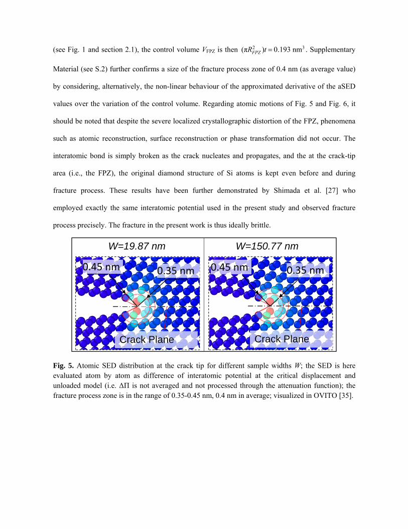
The strain energy density distribution at the crack tip was also analyzed to determine the fracture
process zone, defined as the distance from crack tip where the SED contribution is concentrated.
Fig. 5 depicts a graphical representation of the gradient at the crack tip in the atomic body, while
Fig. 6 shows the main results. For the sake of clarity, it should be noted that this SED is evaluated
as a simple difference between the interatomic potential energy of the sample at the critical
displacement dC and unloaded model for each atom, i.e., it is not averaged and it is not processed
through the attenuation function. It is therefore labeled in Fig. 6 as ∆Π to avoid misunderstanding.
The graphical representation in Fig. 5 shows a clear circular zone where the SED is highly
localized. The picture compares W=19.87 nm and W=150.77 nm. However, same results have been
obtained for all the other geometries: regardless of the specimen size, this zone has an identical
dimension in the range of 0.35-0.45 nm (≈ 1-1.5 atomic distance along the crack plane), in average
0.4 nm, and it is representative of the fracture process zone. This value is in the expected range (~
nm) of ideal brittle material as suggested by Pippan et al. [44] and Shimada et al. [27]. This
conclusion is further confirmed by Fig. 6 that depicts the values of the SED distribution at the crack
tip by considering only upper atoms along the crack plane, normalized by the SED at the crack tip
atom, where the maximum value is found. The primary contribution to the SED is given by the
atoms at the crack tip and concentrated in a distance of approximately 0.35-0.45 nm; at 0.8 nm,
ΔΠ/ΔΠmax decreases to 0.1, making any other contribution at greater distances (but in the proximity
of the crack tip) negligible when averaging over the volume. Same results and precisely the same
trend are found for all the other specimens: again, it is confirmed that the atoms involved in the
fracture process are the same, regardless of the considered size, and are localized around the crack
tip in a distance of approximately 0.4 nm (average value). From these considerations, the FPZ (i.e.
distance from crack tip where the SED contribution is concentrated) is assumed to be 0.4 nm in the
subsequent evaluation of the aSEDDFM. By considering the finite thickness t of the simulation cell
(see Fig. 1 and section 2.1), the control volume VFPZ is then 2 3(π ) 0.193 nmFPZR t . Supplementary
Material (see S.2) further confirms a size of the fracture process zone of 0.4 nm (as average value)
by considering, alternatively, the non-linear behaviour of the approximated derivative of the aSED
values over the variation of the control volume. Regarding atomic motions of Fig. 5 and Fig. 6, it
should be noted that despite the severe localized crystallographic distortion of the FPZ, phenomena
such as atomic reconstruction, surface reconstruction or phase transformation did not occur. The
interatomic bond is simply broken as the crack nucleates and propagates, and the at the crack-tip
area (i.e., the FPZ), the original diamond structure of Si atoms is kept even before and during
fracture process. These results have been further demonstrated by Shimada et al. [27] who
employed exactly the same interatomic potential used in the present study and observed fracture
process precisely. The fracture in the present work is thus ideally brittle.
Fig. 5. Atomic SED distribution at the crack tip for different sample widths W; the SED is here evaluated atom by atom as difference of interatomic potential at the critical displacement and unloaded model (i.e. ΔΠ is not averaged and not processed through the attenuation function); the fracture process zone is in the range of 0.35-0.45 nm, 0.4 nm in average; visualized in OVITO [35].
W=19.87 nm W=150.77 nm
Crack Plane
0.35 nm 0.45 nm 0.35 nm 0.45 nm
Crack Plane
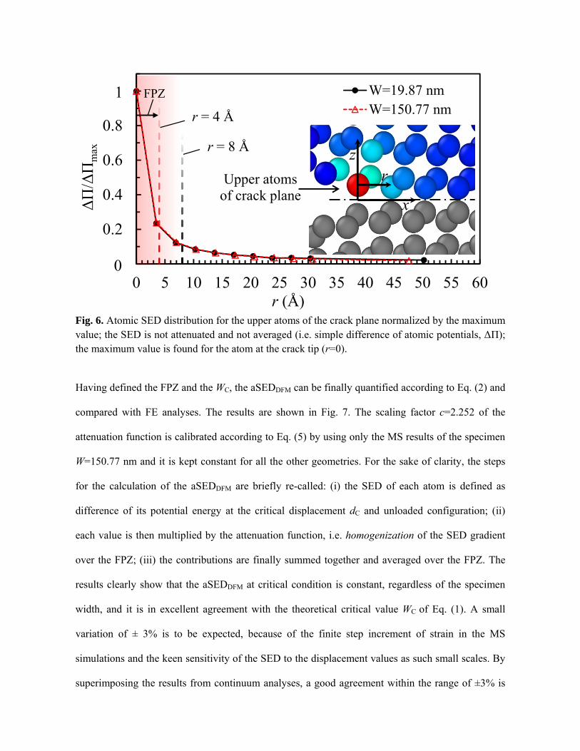
Fig. 6. Atomic SED distribution for the upper atoms of the crack plane normalized by the maximum value; the SED is not attenuated and not averaged (i.e. simple difference of atomic potentials, ΔΠ); the maximum value is found for the atom at the crack tip (r=0).
Having defined the FPZ and the WC, the aSEDDFM can be finally quantified according to Eq. (2) and
compared with FE analyses. The results are shown in Fig. 7. The scaling factor c=2.252 of the
attenuation function is calibrated according to Eq. (5) by using only the MS results of the specimen
W=150.77 nm and it is kept constant for all the other geometries. For the sake of clarity, the steps
for the calculation of the aSEDDFM are briefly re-called: (i) the SED of each atom is defined as
difference of its potential energy at the critical displacement dC and unloaded configuration; (ii)
each value is then multiplied by the attenuation function, i.e. homogenization of the SED gradient
over the FPZ; (iii) the contributions are finally summed together and averaged over the FPZ. The
results clearly show that the aSEDDFM at critical condition is constant, regardless of the specimen
width, and it is in excellent agreement with the theoretical critical value WC of Eq. (1). A small
variation of ± 3% is to be expected, because of the finite step increment of strain in the MS
simulations and the keen sensitivity of the SED to the displacement values as such small scales. By
superimposing the results from continuum analyses, a good agreement within the range of ±3% is
0.0
0.2
0.4
0.6
0.8
1.0
0 5 10 15 20 25 30 35 40 45 50 55 60
ΔΠ
/ΔΠ
max
r (Å)
W=19.87 nmW=150.77 nm
0
1
r = 8 Å
r = 4 Å
z
x
rUpper atoms of crack plane
FPZ
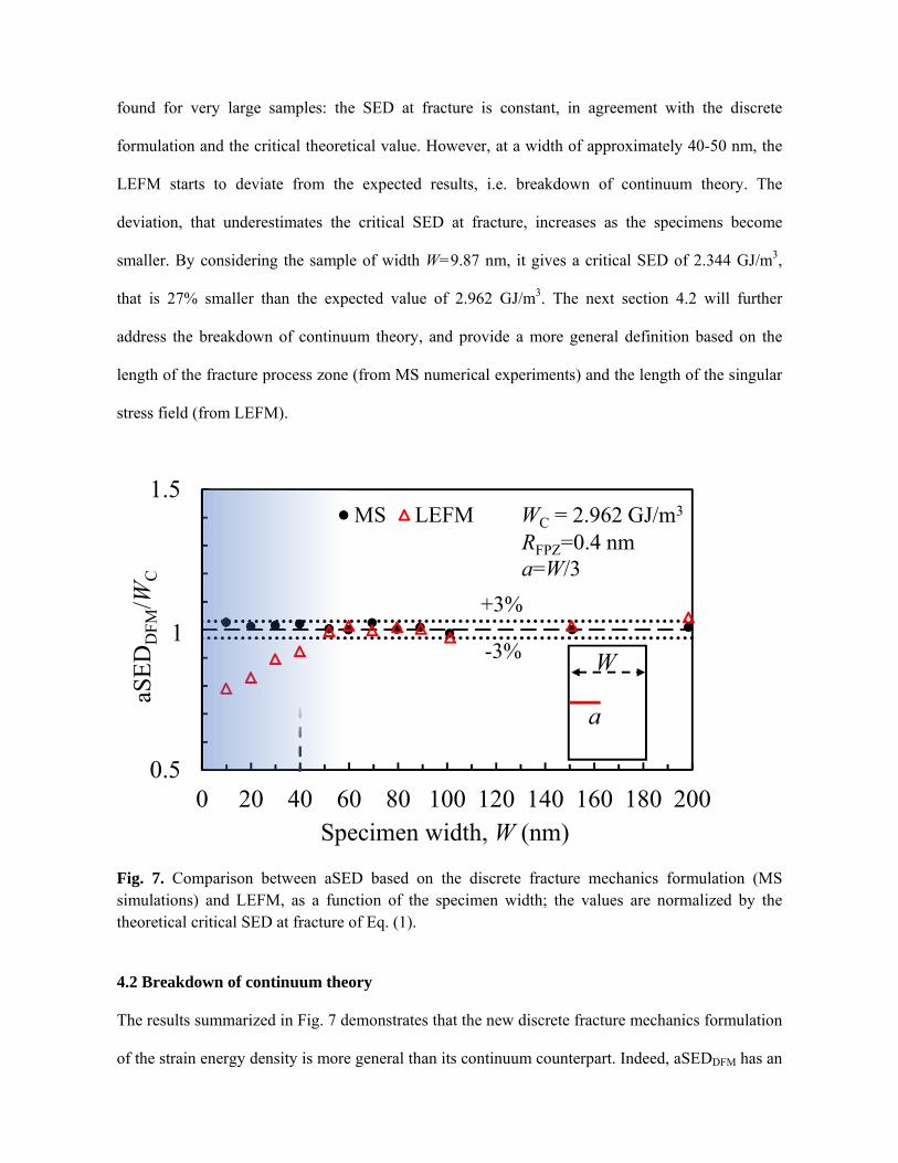
found for very large samples: the SED at fracture is constant, in agreement with the discrete
formulation and the critical theoretical value. However, at a width of approximately 40-50 nm, the
LEFM starts to deviate from the expected results, i.e. breakdown of continuum theory. The
deviation, that underestimates the critical SED at fracture, increases as the specimens become
smaller. By considering the sample of width W=9.87 nm, it gives a critical SED of 2.344 GJ/m3,
that is 27% smaller than the expected value of 2.962 GJ/m3. The next section 4.2 will further
address the breakdown of continuum theory, and provide a more general definition based on the
length of the fracture process zone (from MS numerical experiments) and the length of the singular
stress field (from LEFM).
Fig. 7. Comparison between aSED based on the discrete fracture mechanics formulation (MS simulations) and LEFM, as a function of the specimen width; the values are normalized by the theoretical critical SED at fracture of Eq. (1).
4.2 Breakdown of continuum theory
The results summarized in Fig. 7 demonstrates that the new discrete fracture mechanics formulation
of the strain energy density is more general than its continuum counterpart. Indeed, aSEDDFM has an
0.5
1
1.5
0 20 40 60 80 100 120 140 160 180 200
aSE
DD
FM
/WC
MS LEFM
Specimen width, W (nm)
1
RFPZ=0.4 nm
-3%
+3%
WC = 2.962 GJ/m3
a=W/3
a
W

excellent agreement with the critical theoretical value regardless of the specimen size, while
continuum formulation fails below a width W of 40-50 nm. However, a more general definition of
the length scale beyond which the continuum formulations fails can be provided by analyzing the
length of the FPZ (evaluated from MS results), and the K-dominated zone ΛK (from LEFM
analyses) defined as the distance from the crack tip at which the stresses deviate 5% from the
theoretical r0.5 field. It is shown in Figure 8(b) that the largest specimen has a ΛK of approximately
7.78 nm, a quite significant value if compared to the FPZ of 0.4 nm. However, for the small sample
in Fig. 8(a), the length of ΛK decreases to only 0.42 nm, very close to the FPZ size. In other words,
when reducing the samples widths, K-dominated zone ΛK shrinks down, while the FPZ remains
constant. At a critical length, the primary assumption of the LEFM formulation RFPZ<<ΛK is not
satisfied anymore. This aspect is highlighted in Fig. 9 that permits to quantify the ratio between ΛK
and the FPZ at which the LEFM deviates from MS results. When the singular stress field is in the
range of 4 to 5 times the FPZ (W=40-50 nm), i.e. 1.5-2 nm, continuum fracture mechanics fails.
Similar results have been recently confirmed by Shimada et al. [27] who employed sophisticated
numerical experiments on pre-cracked nanoscale specimens. Those authors estimated a fracture
process zone of approximately 0.4-0.6 nm, and a low limit of continuum fracture mechanics in the
range of 3-6 the FPZ. As long as the non-linear behavior is well confined in a FPZ very small in
comparison to the K-dominated region, classic LEFM still valid. This conclusion justifies why
several authors have successfully applied classic concepts to small scales [15,16,50–52].
Considerations and analyses on stress intensity factors and fracture toughness have been
intentionally ignored to focus on the energy concepts only. However, it should be noted that WC can
characterize the fracture at different scales, i.e. it is scale-independent, and this results further
confirmed that the fracture toughness of ideal brittle materials is fundamentally inherent [16,52].
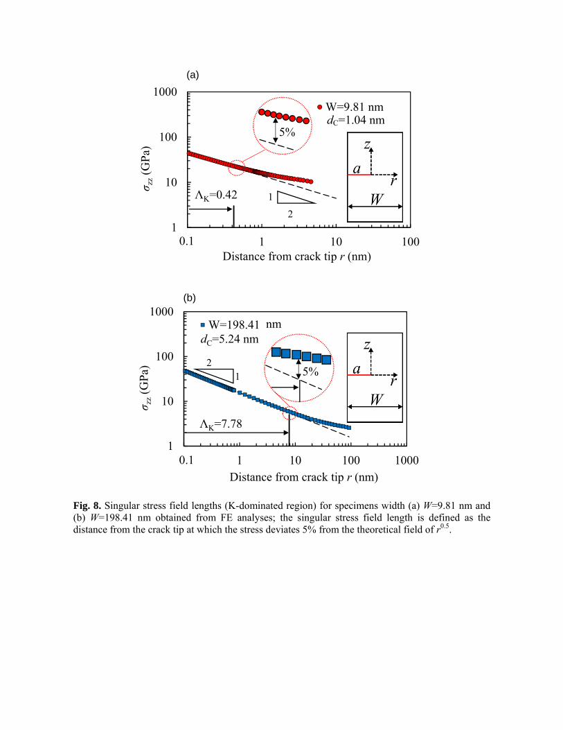
Fig. 8. Singular stress field lengths (K-dominated region) for specimens width (a) W=9.81 nm and (b) W=198.41 nm obtained from FE analyses; the singular stress field length is defined as the distance from the crack tip at which the stress deviates 5% from the theoretical field of r0.5.
1
10
100
1000
0 1 10 100
σ zz
(GP
a)
Distance from crack tip r (nm)
W=9.81 nm
0.1
2
1 ΛK=0.42
5%
1
10
100
1000
0 1 10 100 1000
σ zz
(GP
a)
Distance from crack tip r (nm)
W=198.41
0.1
ΛK=7.78
21 5%
nmdC=5.24 nm
dC=1.04 nm
(a)
(b)
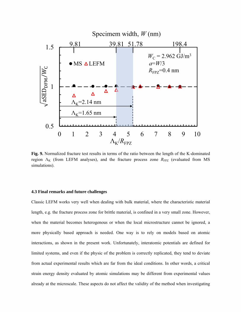
Fig. 9. Normalized fracture test results in terms of the ratio between the length of the K-dominated region ΛK (from LEFM analyses), and the fracture process zone RFPZ (evaluated from MS simulations).
4.3 Final remarks and future challenges
Classic LEFM works very well when dealing with bulk material, where the characteristic material
length, e.g. the fracture process zone for brittle material, is confined in a very small zone. However,
when the material becomes heterogenous or when the local microstructure cannot be ignored, a
more physically based approach is needed. One way is to rely on models based on atomic
interactions, as shown in the present work. Unfortunately, interatomic potentials are defined for
limited systems, and even if the physic of the problem is correctly replicated, they tend to deviate
from actual experimental results which are far from the ideal conditions. In other words, a critical
strain energy density evaluated by atomic simulations may be different from experimental values
already at the microscale. These aspects do not affect the validity of the method when investigating
0.5
1
1.5
0 1 2 3 4 5 6 7 8 9 10
MS LEFM
ΛK/RFPZ
RFPZ=0.4 nm
WC = 2.962 GJ/m3
a=W/3
9.81 39.81 51.78 198.4
Specimem width, W (nm)
ΛK=1.65 nm
ΛK=2.14 nm aSED
⁄
the physical processes involved but indeed represent a future challenge if the final aim is the
proposition of a universal approach that spans different materials and that correctly estimates actual
experimental results.
The present work has considered ideal brittle fracture only, under monotonic mode I load. It is
undoubted that the real big challenge is the fatigue phenomenon. In this regard, it will be crucial the
evaluation of the scale at which mechanisms of fatigue occur and their scale transitions to finally
propose a more general scale-independent formulation or to improve the current approaches.
Atomic simulations and small-scale experiments can provide enormous contribution when
investigating, for example, the role of dislocations, microstructure, and short-crack growth. When
dealing with fatigue, it should be expected a different size of the fracture process zone, since the
physical processes involved are different than those of ideal brittle fracture, and occur at a different
scale level [44].
Concluding, the study was limited to the characterization of cracked components under mode I
loading since the main target was a preliminary investigation of the breakdown of continuum theory
based on a reformulated discrete SED approach. Extension of the approach to other loading
conditions and notches is undoubtedly intriguing but left for future work. In cracked components,
fracture occurs obviously by atomic bond breaking at the crack tip. However, in the case of large
notches, authors have found some difficulties to identify a priori the proper atomic bond at which
the fracture would occur and to correctly place the small control volume. Indeed, according to
[33,43] and to section 3 briefly, in the case of blunt notches the area of the control volume assumes
a crescent shape and it is centred at distance “r0” from the notch root; in case of mixed mode, the
control volume is rigidly rotated and centred on the point where the SED reaches its maximum
value. These definitions imply the implicit knowledge or assumption of the location of the crack
initiation, and place the control volume accordingly.
Finally, the definition of the critical SED in Eq. (1) has been provided by considering a crack along
the cleavage plane (111) and the Young’s modulus accordingly, i.e. in its scalar form. A more
general formulation would necessarily involve a full consideration of the anisotropic behaviour, and
it is left for future work. Success in this direction would provide a method that is both scale- and
potentially (based on results at the macroscale) geometric independent, i.e., it would characterize
successfully notches and cracks at any scale, while remaining very simple. Geometric independency
is, indeed, the main advantage when employing the classic aSED formulation at the macroscale (see
e.g. [43]).
5. Conclusions
The present work investigated the ideal brittle fracture at macro- to nano- (even atomic) scales, and
proposed a new formulation of the averaged strain energy density based on discrete fracture
mechanics theory, namely aSEDDFM. The strain energy density was defined as a function of the
interatomic potential, homogenized through an attenuation function, and averaged over the fracture
process zone. A series of numerical experiments based on MS simulations on ideal brittle fracture
in silico under mode I loading were realized to support and verify the formulation. The approach
was finally compared with continuum fracture mechanics theory. The main conclusions can be
summarized as follows:
The proposed formulation of the aSEDDFM is scale independent, and correctly characterize
the fracture from the macro to the nanoscale under mode I loading condition;
Continuum-based formulation of the aSED fails to describe the fracture below a critical size;
The critical K-dominated length at which continuum formulation fails, i.e. breakdown of
continuum theory, is found to be in the range of 4-5 times the fracture process zone;
A singular stress field of just a few nanometers in agreement with classic LEFM formulation
is still present even for the smallest specimens;
The ideal brittle fracture is governed by atomic bond breaking at the crack tip since the
fracture process zone is constant (scale independent) and approximately in the range of
0.35-0.45 nm (based on SED gradient), regardless of the specimen size;
It is demonstrated that, if the discrete nature of atoms is considered, the critical strain energy
density at fracture is constant and scale independent, thus fracture toughness is
fundamentally inherent as verified by other authors [27,52].
The work is limited, preliminarily, to mode I loading of cracked components; however, the
vast literature on the classic aSED concept has demonstrated a high degree of validity by
assessing both static and fatigue behaviour of components of different geometries, under
different loading conditions and made of different materials. As a future work, further
investigation of those additional cases should be performed, as well as additional
orientations of the samples should be considered.
Acknowledgments
This work was supported by the Japan Society for the Promotion of Science (JSPS) (Grant-in-Aid
for JSPS Fellows No.16F16366, KAKENHI 18H05241, 18K18806 and 17H03145), Academy of
Finland (project number 298762 mFAT, 310828 StrainPath).
P.G. wrote the paper and is the main contributor of the proposed ideas; Y.H. realized part of the MS
simulations; T.S. gave valuable support on the realization of the MS simulations and their
discussion; T.K. revised the work and gave valuable comments on the manuscript. The first author
is grateful to Prof. J. Romanoff and H. Remes (Aalto University).
Bibliography
[1] A.A. Griffith, The phenomena of rupture and flow in solids, Philos. Trans. R. Soc. London.
221 (1921) 163–198.
[2] T. Sumigawa, T. Kitamura, In-Situ Mechanical Testing of Nano-Component in TEM, in: K.
Maaz (Ed.), Transm. Electron Microsc., InTech, 2012: pp. 355–380.
[3] D.S. Gianola, A. Sedlmayr, R. Mönig, C.A. Volkert, R.C. Major, E. Cyrankowski, S.A.S.
Asif, O.L. Warren, O. Kraft, In situ nanomechanical testing in focused ion beam and
scanning electron microscopes, Rev. Sci. Instrum. 82 (2011) 063901.
doi:10.1063/1.3595423.
[4] M.J. Pfeifenberger, M. Mangang, S. Wurster, J. Reiser, A. Hohenwarter, W. Pfleging, D.
Kiener, R. Pippan, The use of femtosecond laser ablation as a novel tool for rapid micro-
mechanical sample preparation, Mater. Des. 121 (2017) 109–118.
doi:10.1016/j.matdes.2017.02.012.
[5] T. Kitamura, T. Sumigawa, H. Hirakata, T. Shimada, Fracture Nanomechanics, 2nd ed., Pan
Stanford Publishing, Singapore, 2016.
[6] Y. Yan, T. Sumigawa, T. Kitamura, A Robust in situ TEM Experiment for Characterizing the
Fracture Toughness of the Interface in Nanoscale Multilayers, Exp. Mech. 58 (2018) 721–
731. doi:10.1007/s11340-018-0375-6.
[7] J. Ast, M. Ghidelli, K. Durst, M. Goeken, M. Sebastiani, A.M. Korsunsky, A review of
experimental approaches to fracture toughness evaluation at the micro-scale, Mater. Des.
(2019) In Press. doi:10.1016/j.matdes.2019.107762.
[8] F.Y. Cui, R.P. Vinci, A chevron-notched bowtie micro-beam bend test for fracture toughness
measurement of brittle materials, Scr. Mater. 132 (2017) 53–57.
doi:10.1016/j.scriptamat.2017.01.031.
[9] F. Iqbal, J. Ast, M. Göken, K. Durst, In situ micro-cantilever tests to study fracture properties
of NiAl single crystals, Acta Mater. 60 (2012) 1193–1200.
doi:10.1016/j.actamat.2011.10.060.
[10] D. Kupka, N. Huber, E.T. Lilleodden, A combined experimental-numerical approach for
elasto-plastic fracture of individual grain boundaries, J. Mech. Phys. Solids. 64 (2014) 455–
467. doi:10.1016/j.jmps.2013.12.004.
[11] P. Gallo, T. Sumigawa, T. Kitamura, Experimental characterization at nanoscale of single
crystal silicon fracture toughness, Frat. Ed Integrità Strutt. 13 (2019) 408–415.
doi:10.3221/IGF-ESIS.47.31.
[12] E. Bitzek, J.R. Kermode, P. Gumbsch, Atomistic aspects of fracture, Int. J. Fract. 191 (2015)
13–30. doi:10.1007/s10704-015-9988-2.
[13] P. Andric, W.A. Curtin, Atomistic modeling of fracture, Model. Simul. Mater. Sci. Eng. 27
(2018) 013001. doi:10.1088/1361-651x/aae40c.
[14] M. Mosby, K. Matouš, Computational homogenization at extreme scales, Extrem. Mech.
Lett. 6 (2016) 68–74. doi:10.1016/j.eml.2015.12.009.
[15] T. Sumigawa, H. Fang, E. Kawai, T. Kitamura, Mechanics of fracture in nanometer-scale
components, Mech. Eng. Rev. 1 (2014) SMM0007–SMM0007.
doi:10.1299/mer.2014smm0007.
[16] T. Sumigawa, T. Shimada, S. Tanaka, H. Unno, N. Ozaki, S. Ashida, T. Kitamura, Griffith
Criterion for Nanoscale Stress Singularity in Brittle Silicon, ACS Nano. 11 (2017) 6271–
6276. doi:10.1021/acsnano.7b02493.
[17] H. Yin, H.J. Qi, F. Fan, T. Zhu, B. Wang, Y. Wei, Griffith criterion for brittle fracture in
graphene, Nano Lett. 15 (2015) 1918–1924. doi:10.1021/nl5047686.
[18] K. Huang, T. Shimada, N. Ozaki, Y. Hagiwara, T. Sumigawa, L. Guo, T. Kitamura, A
unified and universal Griffith-based criterion for brittle fracture, Int. J. Solids Struct. 128
(2017) 67–72. doi:10.1016/j.ijsolstr.2017.08.018.
[19] P. Gallo, Y. Yan, T. Sumigawa, T. Kitamura, Fracture Behavior of Nanoscale Notched
Silicon Beams Investigated by the Theory of Critical Distances, Adv. Theory Simulations. 1
(2018) 1700006. doi:10.1002/adts.201700006.
[20] P. Gallo, T. Sumigawa, T. Kitamura, F. Berto, Static assessment of nanoscale notched silicon
beams using the averaged strain energy density method, Theor. Appl. Fract. Mech. 95 (2018)
261–269. doi:10.1016/j.tafmec.2018.03.007.
[21] P. Gallo, T. Sumigawa, T. Kitamura, F. Berto, Evaluation of the strain energy density control
volume for a nanoscale singular stress field, Fatigue Fract. Eng. Mater. Struct. 39 (2016)
1557–1564. doi:10.1111/ffe.12468.
[22] T. Kitamura, T. Sumigawa, T. Shimada, L. Van Lich, Challenge toward nanometer scale
fracture mechanics, Eng. Fract. Mech. 187 (2018) 33–44.
doi:10.1016/j.engfracmech.2017.10.009.
[23] G. Dehm, B.N. Jaya, R. Raghavan, C. Kirchlechner, Overview on micro- and
nanomechanical testing: New insights in interface plasticity and fracture at small length
scales, Acta Mater. 142 (2018) 248–282. doi:10.1016/j.actamat.2017.06.019.
[24] E. Tarleton, D.S. Balint, J. Gong, A.J. Wilkinson, A discrete dislocation plasticity study of
the micro-cantilever size effect, Acta Mater. 88 (2015) 271–282.
doi:10.1016/j.actamat.2015.01.030.
[25] T. Shimada, T. Kitamura, Fracture Mechanics at Atomic Scales, in: H. Altenbach, T.
Matsuda, D. Okumura (Eds.), Adv. Struct. Mater., Springer International Publishing, Cham,
2015: pp. 379–396. doi:10.1007/978-3-319-19440-0_17.
[26] N.M. Pugno, R.S. Ruoff, Quantized fracture mechanics, Philos. Mag. 84 (2004) 2829–2845.
doi:10.1080/14786430412331280382.
[27] T. Shimada, K. Ouchi, Y. Chihara, T. Kitamura, Breakdown of Continuum Fracture
Mechanics at the Nanoscale, Sci. Rep. 5 (2015) 8596. doi:10.1038/srep08596.
[28] A.M. Freudenthal, The Inelastic Behavior of Engineering Materials and Structures, John
Wiley & Sons, New York, 1950.
[29] R. Hill, A variational principle of maximum plastic work in classical plasticity, Q. J. Mech.
Appl. Math. 1 (1948) 18–28. doi:10.1093/qjmam/1.1.18.
[30] Q.M. Li, Strain energy density failure criterion, Int. J. Solids Struct. 38 (2001) 6997–7013.
doi:10.1016/S0020-7683(01)00005-1.
[31] P. Lazzarin, R. Zambardi, A finite-volume-energy based approach to predict the static and
fatigue behavior of components with sharp V-shaped notches, Int. J. Fract. 112 (2001) 275–
298. doi:10.1023/A:1013595930617.
[32] P. Lazzarin, R. Zambardi, The Equivalent Strain Energy Density approach re-formulated and
applied to sharp V-shaped notches under localized and generalized plasticity, Fatigue Fract.
Eng. Mater. Struct. 25 (2002) 917–928. doi:10.1046/j.1460-2695.2002.00543.x.
[33] F. Berto, P. Lazzarin, A review of the volume-based strain energy density approach applied
to V-notches and welded structures, Theor. Appl. Fract. Mech. 52 (2009) 183–194.
doi:10.1016/j.tafmec.2009.10.001.
[34] S. Plimpton, Fast Parallel Algorithms for Short-Range Molecular Dynamics, J. Comput.
Phys. 117 (1995) 1–19. doi:10.1006/jcph.1995.1039.
[35] A. Stukowski, Visualization and analysis of atomistic simulation data with OVITO–the Open
Visualization Tool, Model. Simul. Mater. Sci. Eng. 18 (2010) 015012. doi:10.1088/0965-
0393/18/1/015012.
[36] D. Holland, M. Marder, Ideal Brittle Fracture of Silicon Studied with Molecular Dynamics,
Phys. Rev. Lett. 80 (1998) 746–749. doi:10.1103/PhysRevLett.80.746.
[37] D. Holland, M. Marder, Cracks and atoms, Adv. Mater. 11 (1999) 793–806.
doi:10.1002/(SICI)1521-4095(199907)11:10<793::AID-ADMA793>3.0.CO;2-B.
[38] F.H. Sillinger, T.A. Weber, Computer simulation of local order in condensed phases of
silicon, Phys. Rev. B. 31 (1985) 5262–5271. doi:10.1103/PhysRevB.31.5262.
[39] J.J. Wortman, R.A. Evans, Young’s modulus, shear modulus, and poisson’s ratio in silicon
and germanium, J. Appl. Phys. 36 (1965) 153–156. doi:10.1063/1.1713863.
[40] E. Bitzek, P. Koskinen, F. Gähler, M. Moseler, P. Gumbsch, Structural Relaxation Made
Simple, Phys. Rev. Lett. 97 (2006) 170201. doi:10.1103/PhysRevLett.97.170201.
[41] E. Mandenci, I. Guven, The finite element method and applications in engineering using
ANSYS, Springer, 2006.
[42] P. Lazzarin, F. Berto, Control volumes and strain energy density under small and large scale
yielding due to tension and torsion loading, Fatigue Fract. Eng. Mater. Struct. 31 (2008) 95–
107. doi:10.1111/j.1460-2695.2007.01206.x.
[43] F. Berto, P. Lazzarin, Recent developments in brittle and quasi-brittle failure assessment of
engineering materials by means of local approaches, Mater. Sci. Eng. R Reports. 75 (2014)
1–48. doi:10.1016/j.mser.2013.11.001.
[44] R. Pippan, S. Wurster, D. Kiener, Fracture mechanics of micro samples: Fundamental
considerations, Mater. Des. 159 (2018) 252–267. doi:10.1016/j.matdes.2018.09.004.
[45] A.R. Torabi, F. Berto, Fracture Assessment of Blunt V-Notched Graphite Specimens by
Means of the Strain Energy Density, Strength Mater. 45 (2013) 635–647.
doi:10.1007/s11223-013-9500-z.
[46] M.R. Ayatollahi, F. Berto, A. Campagnolo, P. Gallo, K. Tang, Review of local strain energy
density theory for the fracture assessment of V-notches under mixed mode loading, Eng.
Solid Mech. 5 (2017) 113–132. doi:10.5267/j.esm.2017.3.001.
[47] P. Lazzarin, F. Berto, M. Elices, J. Gómez, Brittle failures from U- and V-notches in mode I
and mixed, I + II, mode: a synthesis based on the strain energy density averaged on finite-
size volumes, Fatigue Fract. Eng. Mater. Struct. 32 (2009) 671–684. doi:10.1111/j.1460-
2695.2009.01373.x.
[48] Z.P. Bažant, J. Ožbolt, Nonlocal Microplane Model for Fracture, Damage, and Size Effect in
Structures, J. Eng. Mech. 116 (1990) 2485–2505. doi:10.1061/(ASCE)0733-
9399(1990)116:11(2485).
[49] Z.P. Bažant, M. Jirásek, Nonlocal Integral Formulations of Plasticity and Damage: Survey of
Progress, J. Eng. Mech. 128 (2002) 1119–1149. doi:10.1061/(ASCE)0733-
9399(2002)128:11(1119).
[50] P. Gallo, T. Sumigawa, T. Shimada, Y. Yan, T. Kitamura, Investigation into the Breakdown
of Continuum Fracture Mechanics at the Nanoscale: Synthesis of Recent Results on Silicon,
in: E.E. Gdoutos (Ed.), Proc. First Int. Conf. Theor. Appl. Exp. Mech., Springer International
Publishing, Cham, 2019: pp. 205–210. doi:10.1007/978-3-319-91989-8_45.
[51] L. Guo, T. Kitamura, Y. Yan, T. Sumigawa, K. Huang, Fracture mechanics investigation on
crack propagation in the nano-multilayered materials, Int. J. Solids Struct. 64–65 (2015)
208–220. doi:10.1016/j.ijsolstr.2015.03.025.
[52] T. Sumigawa, S. Ashida, S. Tanaka, K. Sanada, T. Kitamura, Fracture toughness of silicon in
nanometer-scale singular stress field, Eng. Fract. Mech. 150 (2015) 161–167.
doi:10.1016/j.engfracmech.2015.05.054.