Embed Size (px)
Citation preview
Thomas O. Mason1
Barry S. Rose1
Joseph H. Goodman2
Received December 11 , 1985; accepted after revision March 15, 1986.
, Department of Radiology, The Ohio State University Hospitals, 410 W. 10th Avenue, Columbus, OH 43210. Address reprint requests to T. O. Mason.
2 Division of Neurosurgery, The Ohio State University Hospitals, Columbus, OH 43210.
AJNR 7:829-831 , September/October 1986 0195-6108/86/0705-0829 © American Society of Neuroradiology
Gas Bubbles in Polymethylmethacrylate Cranioplasty Simulating Abscesses: CT Appearance
829
Polymethylmethacrylate (PMMA) cranioplasty procedures were performed on 20 patients over a 2-year period. Nine of these patients had a total of 17 CT examinations, performed when clinically indicated. On 16 of the 17 CT scans, the appearance of the cranioplasty plate was characteristic of plates with gas bubbles. The appearance of these bubbles was stable over an extended period of time, ruling out clinical reasons for this appearance. The original interpretations of the CT scans were variable, inconclusive, or even erroneous. An understanding of the application of PMMA plates and their characteristics is necessary to accurately interpret the CT appearance of the PMMA cranioplasty plate.
Polymethylmethacrylate (PMMA) is one of the most common prosthetic materials used for plastic repair of craniotomy defects. Most cranioplasty procedures using PMMA to correct a cranial defect after trauma or craniotomy are performed some time after the initial insult in order to avoid potential complications of attendant edema or infection. The morbidity associated with the implantation of the prosthesis in this stabilized population is thereby greatly reduced . Because there is usually little clinical indication for performing CT on these patients, the appearance of the cranioplasty may not be attributed to the inherent characteristics of the plate, but may be misinterpreted to represent infection.
We have reviewed the clinical data and radiographic interpretations of patients on whom CT of the brain was performed after PMMA cranioplasty. An understanding of some of the physical and chemical properties of methylmethacrylate (MMA), the polymerization process, and the cranioplasty technique is necessary to obtain an accurate interpretation of the CT scan through the level of the PMMA prostheSiS.
Materials and Methods
PMMA cranioplasty procedures were performed on 20 patients at our institution in the past 2 years. Reasons for the original craniotomy and/or craniectomy varied in these patients and included excision of tumors , elevation of fractures , and evacuation of hematomas. The clinical data and radiographic interpretations of CT scans taken after cranioplasty were reviewed .
A self-curing MMA product (Cranioplastic, L. D. Caulk Co ., Milford, DE) was used for all patients. The liquid component is added to the solid component and mixed rapidly to ensure homogeneity of material. In a few minutes the conSistency of the mixture becomes doughlike and the material is easily handled. After the incision and retraction of the skin , subcutaneous tissues, and galea, excision of the cicatrix around the defect is performed, exposing healthy bone circumferentially. The semiplastic MMA is then troweled directly onto the fibrous tissue overlying the dura mater and shaped to the form of the skull. Copious irrigation is used to remove the excess heat from polymerization . Holes are then drilled into the plate and adjacent s.kull, and the PMMA is sutured to prevent future slippage. The galea, subcutaneous tissues, and skin are then replaced and sutured. An alternative technique uses an underlying stainless steel mesh that is cut to conform to the defect. The mesh is sutured into position and the
830 MASON ET AL. AJNR:7, September/October 1986
A B
A B
MMA is applied as described above. CT attenuation values were obtained from the solid-appearing portions of the plates, from the gas bubbles within the plates , and from premanufactured PMMA.
Results
CT scans were performed on nine patients postoperatively to evaluate for tumor recurrence, fluid reaccumulation , or cause of change in clinical status. Eight of these patients had plates without wire mesh reinforcement. Sixteen CT examinations were performed on these eight patients, and every study demonstrated a collection of gas bubbles in the region of the cranioplasty plate.
We retrospectively reviewed the original interpretations of these examinations. Seven of these studies were done within a week of the procedure, and the gas was attributed to air introduced at the time of surgery, although gas related to infection was considered. In five studies the collections of gas were just described and no attempt was made to ascribe a cause or significance to the findings. The gas collections were
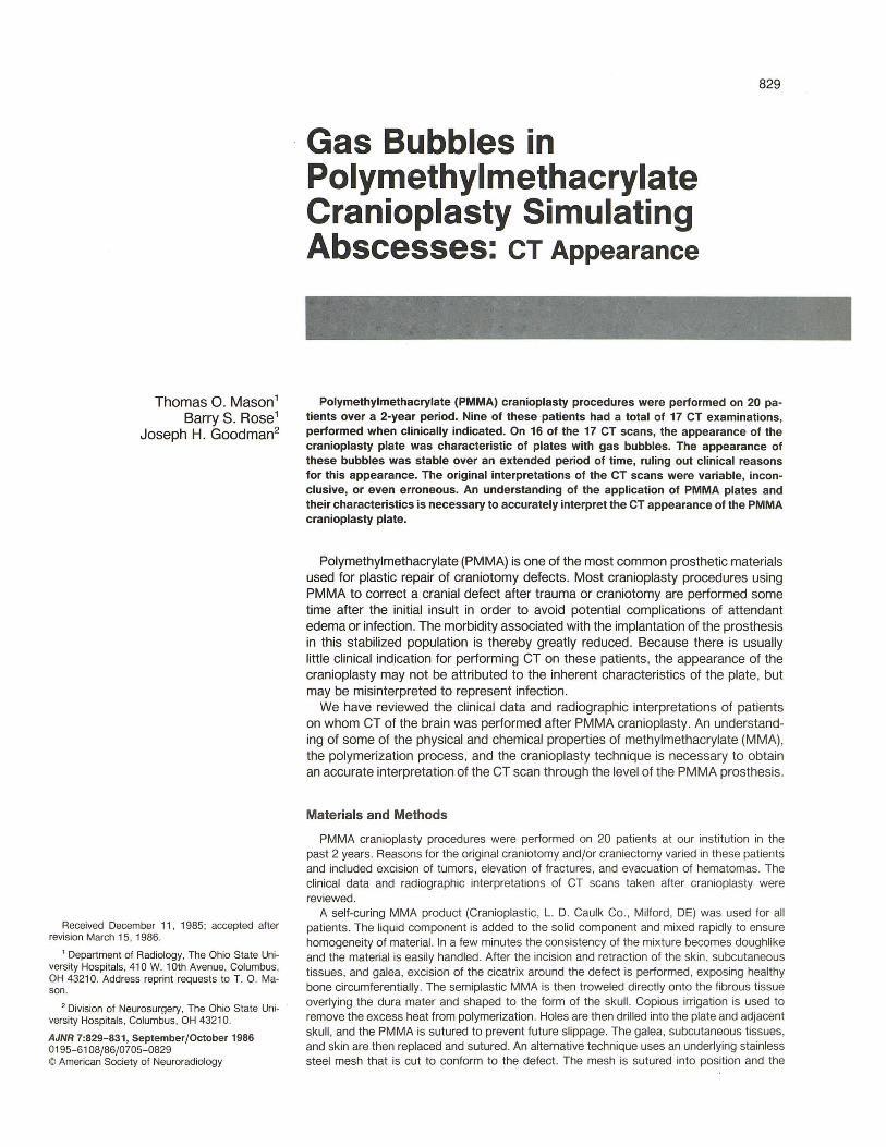
Fig. 1.-A, Precontrast scan showing inhomogeneity and gas bubbles within the poly methylmethacrylate plate. B, IV-contrast enhancement. Borders of the plate are defined by skull , enhancing meninges (black arrows), and enhancing scalp (white arrows) .
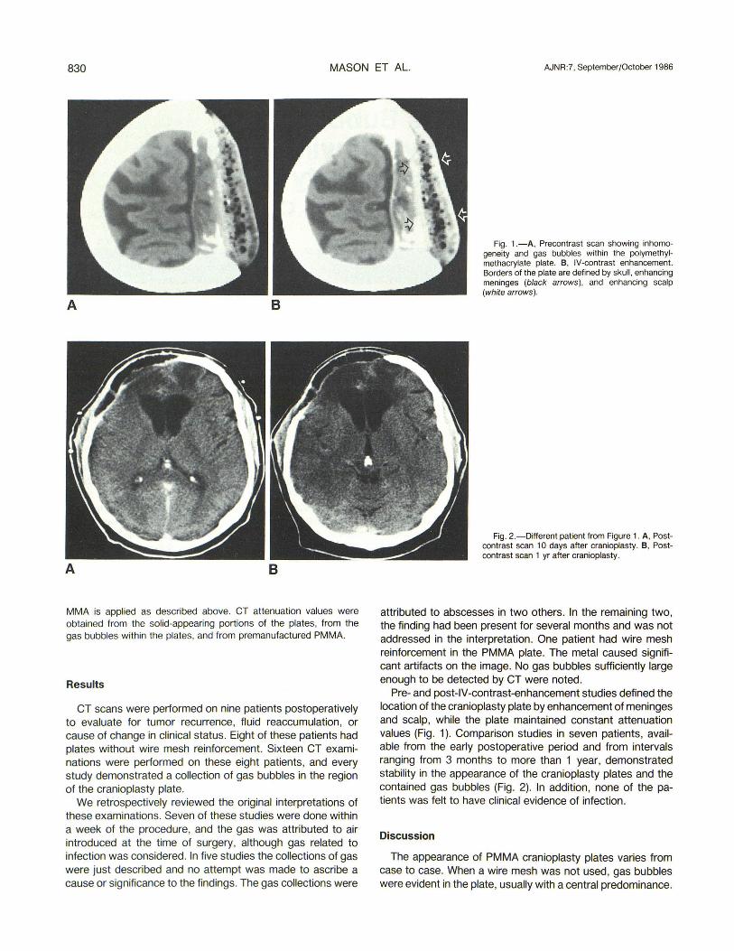
Fig. 2.-Different patient from Figure 1. A, Postcontrast scan 10 days after cranioplasty . B, Postcontrast scan 1 yr after cranioplasty .
attributed to abscesses in two others. In the remaining two, the finding had been present for several months and was not addressed in the interpretation. One patient had wire mesh reinforcement in the PMMA plate. The metal caused significant artifacts on the image. No gas bubbles sufficiently large enough to be detected by CT were noted.
Pre- and post-IV-contrast-enhancement studies defined the location of the cranioplasty plate by enhancement of meninges and scalp, while the plate maintained constant attenuation values (Fig . 1). Comparison studies in seven patients, available from the early postoperative period and from intervals ranging from 3 months to more than 1 year, demonstrated stability in the appearance of the cranioplasty plates and the contained gas bubbles (Fig. 2). In addition, none of the patients was felt to have clinical evidence of infection.
Discussion
The appearance of PMMA cranioplasty plates varies from case to case. When a wire mesh was not used, gas bubbles were evident in the plate, usually with a central predominance.
AJNR:7, September/October 1986 GAS BUBBLES IN CRANIOPLASTY 831
The long-term stability of the appearance of the bubbles makes the probability that this finding is related to abscess very low. None of these patients had clinical evidence of infection.
Bubbles are created by the rapid stirring necessary to mix the components of the plastic homogeneously. The process of polymerization is exothermic. If heat were not dissipated, the temperature of the MMA mass could approach 122°C [1 , 2, 3]. Because the boiling point of MMA is 100°C, temperatures approaching or exceeding this value will cause the MMA to exert a Significant vapor pressure, or even to boil, which also causes gas bubbles within the plate. In addition, the bubbles expand with the rise in temperature. If adjacent bubbles expand and encroach upon each other, they may coalesce, causing larger pockets of gas. Since the polymerization rate is greatest at the maximum temperature, the solidification of the polymer traps the gas collections in their most expanded state. The expansion of the plate due to the enlarging pores is offset mostly by the shrinkage (about 9%) due to the polymerization and the change in density from that of MMA to PMMA [4] .
Too many pores within the plate may compromise the protective integrity of the plate [5, 6, 7]. Because high temperatures lead to an increased number and larger size of the pores, and because high temperatures also have the potential to damage the meninges to which the MMA is applied, copious saline irrigation is used to minimize these consequences. This effectively lowers the exterior surface temperature. Studies have shown, however, that even with saline irrigation, the epidural temperature can rise to 64°C [8] . Damage to the brain is unlikely since the meninges are highly vascularized and effectively remove this heat, so that the subdural temperature has been shown to rise only by 0.55°C [9]. Despite cooling at both surfaces, the internal temperature of the plate remains high because the thermal conductivity of MMAfPMMA is low. Thus, the gas bubbles form predominantly at the plate's center [3 , 10].
No gas bubbles were evident in the patient who had the wire mesh inserted. Although only a single case was available, we believe the absence of significantly large bubbles is related directly to the presence of the wire mesh. It is postulated that the mesh functions as a radiator, distributing the heat evenly throughout the plate, and preventing areas of very high temperature, thereby reducing the production, expansion, and coalescence of gas bubbles .
In patients whose plates have pores that are small or sparse, it may be difficult to define the extent of the plate, since the attenuation values may be similar to soft tissue or brain . This is due to diffuse gas pockets within the plates below the resolution of the CT scanner, causing averaging of the attenuation signals of gas and solid [11] . Premanufactured, pressure-cured plates contain no gas bubbles and have higher attenuation values of 90-110 H. By obtaining both preand post-lV-contrast scans, the cranioplasty pla.te is defined
by the enhanced meninges and scalp and the edges of the skull surrounding it (Fig. 1). The plate can be differentiated from an adjacent isodense fluid collection because the surfaces of the plate are more highly attenuating than the interior [12]. The surface cooling by the saline irrigation and meningeal vessels prevents formation of large bubbles at the plate surfaces and results in a slightly higher surface density than there is internally.
Our experience with the appearance of PMMA cranioplasty plates on CT indicates that there are certain characteristic findings that may be inherent to the plates themselves. Gas bubbles are seen within the plates , with larger bubbles located centrally . Thus, the plates have a slightly higher density at their surfaces. The surface density of the plates, where the gas pores are small, is similar to soft tissue or brain . The extent of the plate can be defined on CT by the IV-contrast enhancement of surrounding tissues.
REFERENCES
1. Swenson LW, Schurman DJ, Piziali RL. Finite element temperature analysis of a total hip replacement and measurement of PMMA curing temperatures. J Biomed Mater Res 1981 ;15 :83-96
2. Taoka H, Kinoshita I, Morimoto H, Sasaki T, Ogawa Y, Shimakawa T. Temperature in the interface between bone and acrylic bone cement. Tokushima J Exp Med 1980;27 :89-92
3. Jefferiss CD, Lee AJC, Ling RSM . Thermal aspects of self-curing polymethylmethacrylate. J Bone Joint Surg [Br] 1975;57:511-518
4. Debrunner HU, Wettstein A, Hofer P. The polymerization of selfcuring acrylic cements and problems due to the cement anchorage of joint prostheses. In: Schaldach M, Hohmann D, in collaboration with Thull R, Hein F, eds. Advances in artificial hip and knee joint technology. New York : Springer-Verlag, 1976:294-324
5. De Wijn JR, Sioof T JH, Driessens FCM. Characterization of bone cements. Acta Orthop Scand 1975;46 :38-51
6. Lindgren L, Drar H, Moller J. Strength of polymethylmethacrylate increased by vacuum mixing. Acta Orthop Scand 1984;55: 536-541
7. Haas SS, Brauer GM , Dickson G. A characterization of polymethyl methacrylate bone cement. J Bone Joint Surg [Am] 1975;57 :380-391
8. ASimacopoulos T J, Papadakis N, Mark VH. A new method of cranioplasty (technical note) . J Neurasurg 1977;47 :790-792
9. Genest AS. Cranioplasty made easier. Surg Neural 1978;10: 255-257
10. Schultz RC. Restoration of frontal contour with methyl methacrylate. Ann Plast Surg 1979;3 :295-303
11 . Beynon J, Sionim L, Kiss KS, Morris C, Lau L. CT appearance of a prosthetic methyl methacrylate mass mistaken for an abscess. Radiology 1984;150 :506
12. Yamaura A, Makino H. Air bubble cavities in the methyl methacrylate plate of cranioplasty acting as a site of foci for persistent infection (case report) . Neural Med Chir (Tokyo ) 1979;19:35-38