Embed Size (px)
Citation preview
www.elsevier.com/locate/gca
Geochimica et Cosmochimica Acta 71 (2007) 2947–2959
Gas hydrate measurements at Hydrate Ridge usingRaman spectroscopy
K.C. Hester a, R.M. Dunk b, S.N. White c, P.G. Brewer b,E.T. Peltzer b, E.D. Sloan a,*
a Center for Hydrate Research, Colorado School of Mines, Golden, CO 80401, USAb Monterey Bay Aquarium Research Institute, 7700 Sandholdt Road, Moss Landing, CA 95039, USA
c Department of Applied Ocean Physics & Engineering, Woods Hole Oceanographic Institution, Woods Hole, MA 02543, USA
Received 14 November 2006; accepted in revised form 29 March 2007; available online 14 April 2007
Abstract
Oceanic gas hydrates have been measured near the seafloor for the first time using a seagoing Raman spectrometer atHydrate Ridge, Oregon, where extensive layers of hydrates have been found to occur near the seafloor. All of the hydratesanalyzed were liberated from the upper meter of the sediment column near active gas venting sites in water depths of 770–780 m. Hydrate properties, such as structure and composition, were measured with significantly less disturbance to the samplethan would be realized with core recovery. The natural hydrates measured were sI, with methane as the predominant guestcomponent, and minor/trace amounts of hydrogen sulfide present in three of the twelve samples measured. Methane large-to-small cage occupancy ratios of the hydrates varied from 1.01 to 1.30, in good agreement with measurements of laboratorysynthesized and recovered natural hydrates. Although the samples visually appeared to be solid, varying quantities of freemethane gas were detected, indicating the possible presence of occluded gas in a hydrate bubble fabric.� 2007 Elsevier Ltd. All rights reserved.
1. INTRODUCTION
Gas hydrates are naturally occurring compounds thatform in permafrost and ocean margin regions. These mate-rials form when water and small ‘‘guest’’ molecules, such asmethane, react at low temperature, high pressure conditions(typically 275–285 K and 2.5–11 MPa for methane hy-drate). The water crystallizes into a network of hydrogen-bonded molecular cages that contain the guest molecules(Sloan, 1998). Hydrates highly concentrate gases such asmethane, e.g. 1 m3 of methane hydrate can contain theequivalent of 164 m3 of methane at STP (Sloan, 1998).
The three main gas hydrate structures are sI, sII, and sH.The sI hydrate crystal has a unit cell that consists of sixlarge (51262) cages and two small (512) cages. Gases suchas methane, carbon dioxide, and hydrogen sulfide formthe sI framework. The sII hydrate unit cell has eight large
0016-7037/$ - see front matter � 2007 Elsevier Ltd. All rights reserved.
doi:10.1016/j.gca.2007.03.032
* Corresponding author.E-mail address: [email protected] (E.D. Sloan).
(51264) cages and sixteen small (512) cages. Larger compo-nents such as propane form sII hydrate. The sH unit cellhas three cage types: one large (51268), two medium(435663), and three small (512) cages. The sH hydrate, dis-covered by Ripmeester et al. (1987), requires a large guest,such as i-pentane, along with a smaller guest like methane(Sloan, 1998).
In the natural environment, methane constitutes the vastmajority of guest molecules in hydrates (Kvenvolden, 1995;Milkov, 2005). Due to this predominance of methane, sI isthought to be the most common naturally occurring hy-drate structure. However, sII also occurs in some areasdue to the presence of ethane, propane and other higherhydrocarbons, mainly from thermogenic sources (Sloan,1998). In the Gulf of Mexico, naturally-occuring sHhydrate has also been inferred from the presence ofsH-forming hydrocarbons and confirmed using diffractionand spectroscopy at Barkley Canyon (Sassen and MacDon-ald, 1994; Pohlman et al., 2005; Hester, 2007; Lu et al.,2007).
2948 K.C. Hester et al. / Geochimica et Cosmochimica Acta 71 (2007) 2947–2959
Research is ongoing into the importance of gas hydrateswithin the global carbon cycle and hence climate change(Dickens, 2001; Milkov et al., 2003; Milkov, 2005). Themajority of natural gas hydrate accumulations are found inthe marine environment, where this reservoir is estimatedto be at least two orders of magnitude greater than the perma-frost hydrate reservoir (Kvenvolden, 1999; Kvenvolden andLorensen, 2001; Milkov, 2004; Klauda and Sandler, 2005).Based on current available knowledge of gas hydrate distri-butions, Milkov (2004) estimated a total reservoir of 500–2500 Gt of carbon stored as methane hydrate on the conti-nental shelves of the world’s oceans. Conversely, Klaudaand Sandler (2005) present a significantly larger estimate of74,200 Gt of carbon based on a predictive thermodynamicmodel. Even with the uncertainty in these estimates, thisinventory of methane has created much of the present re-search interest in hydrates as a possible potential energysource for the future.
Raman spectroscopy, a non-destructive and non-inva-sive technique, is used to study vibrational modes of mole-cules (Long, 1977) to extract information about the systemof interest. This technique is now routinely employed toinvestigate the properties, including structure and composi-tion, of both synthetic and recovered naturally occurringhydrates (Sum et al., 1997; Uchida et al., 1999; Tulket al., 2000; Koh, 2002). For pure methane hydrate, the Ra-man technique can quantitatively determine the relativeoccupancies of the two hydrate cage types (Subramanian,2000; Wilson et al., 2002). For mixed hydrate guests, thetechnique can determine hydrate composition qualitatively.Further studies will be needed to allow quantification ofmixed hydrate systems. Work has been done to make Ra-man quantitative for other geochemical applications, suchas molar compositions in the gaseous and aqueous phasesand in fluid inclusion analysis (Seitz et al., 1987, 1993,1996; Dunk et al., 2005; White et al., 2006).
While measuring hydrates with Raman spectroscopy isnow becoming routine in the laboratory, the applicationof this technique to oceanic field work is still relativelynew. The MBARI-designed seagoing Raman spectrometer,DORISS, has been deployed to perform laboratory qualitymeasurements on natural ocean systems at depth (Breweret al., 2004; Pasteris et al., 2004; White et al., 2006). Syn-thetic gas hydrates were measured in an ocean environmentat 1000 m depth to qualify the use of this remote Ramantechnique on gas hydrates (Hester et al., 2006). The spectraobtained were of high quality (high signal to noise ratio)and were similar to the corresponding spectra obtained inthe laboratory. The next step was to attempt to measurenatural hydrates on the seafloor with the field Ramanspectrometer.
An important question remains as to what extent therecovery process alters the hydrate from its in situ proper-ties. Pressurized coring techniques have made significantprogress in the recovery of hydrate samples, reducing disso-ciation in comparison to traditional coring (Abegg et al.,2003; Trehu et al., 2003; Milkov et al., 2004). Nevertheless,it is still difficult to quantify the changes in the sample overthe recovery process. Here we present results from an alter-native approach to minimize sample degradation prior to
analysis. In this study, we use a remotely deployed Ramanspectrometer to sample hydrates at the seafloor (i.e. ratherthan bring the sample to the instrument, we took the instru-ment to the sample). These results are compared to spectro-scopic measurements on synthetic laboratory and recoverednatural hydrate samples.
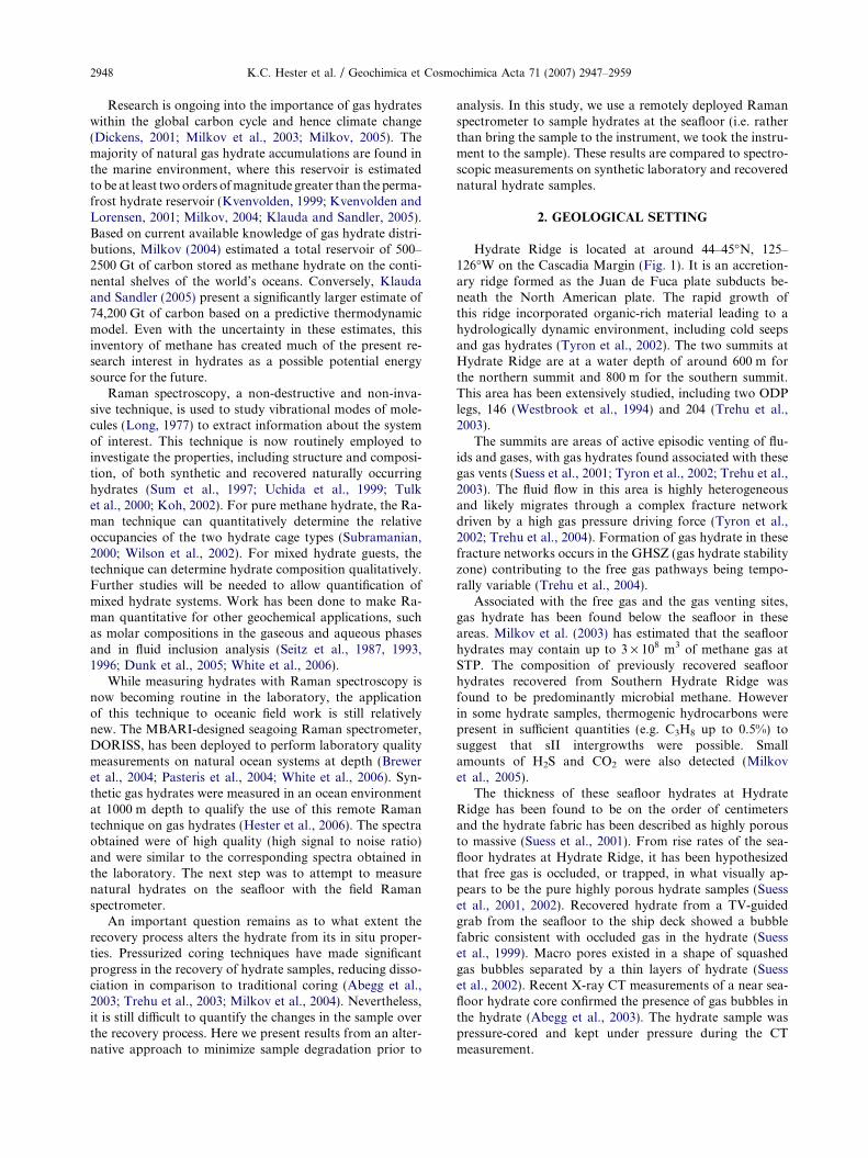
2. GEOLOGICAL SETTING
Hydrate Ridge is located at around 44–45�N, 125–126�W on the Cascadia Margin (Fig. 1). It is an accretion-ary ridge formed as the Juan de Fuca plate subducts be-neath the North American plate. The rapid growth ofthis ridge incorporated organic-rich material leading to ahydrologically dynamic environment, including cold seepsand gas hydrates (Tyron et al., 2002). The two summits atHydrate Ridge are at a water depth of around 600 m forthe northern summit and 800 m for the southern summit.This area has been extensively studied, including two ODPlegs, 146 (Westbrook et al., 1994) and 204 (Trehu et al.,2003).
The summits are areas of active episodic venting of flu-ids and gases, with gas hydrates found associated with thesegas vents (Suess et al., 2001; Tyron et al., 2002; Trehu et al.,2003). The fluid flow in this area is highly heterogeneousand likely migrates through a complex fracture networkdriven by a high gas pressure driving force (Tyron et al.,2002; Trehu et al., 2004). Formation of gas hydrate in thesefracture networks occurs in the GHSZ (gas hydrate stabilityzone) contributing to the free gas pathways being tempo-rally variable (Trehu et al., 2004).
Associated with the free gas and the gas venting sites,gas hydrate has been found below the seafloor in theseareas. Milkov et al. (2003) has estimated that the seafloorhydrates may contain up to 3 · 108 m3 of methane gas atSTP. The composition of previously recovered seafloorhydrates recovered from Southern Hydrate Ridge wasfound to be predominantly microbial methane. Howeverin some hydrate samples, thermogenic hydrocarbons werepresent in sufficient quantities (e.g. C3H8 up to 0.5%) tosuggest that sII intergrowths were possible. Smallamounts of H2S and CO2 were also detected (Milkovet al., 2005).
The thickness of these seafloor hydrates at HydrateRidge has been found to be on the order of centimetersand the hydrate fabric has been described as highly porousto massive (Suess et al., 2001). From rise rates of the sea-floor hydrates at Hydrate Ridge, it has been hypothesizedthat free gas is occluded, or trapped, in what visually ap-pears to be the pure highly porous hydrate samples (Suesset al., 2001, 2002). Recovered hydrate from a TV-guidedgrab from the seafloor to the ship deck showed a bubblefabric consistent with occluded gas in the hydrate (Suesset al., 1999). Macro pores existed in a shape of squashedgas bubbles separated by a thin layers of hydrate (Suesset al., 2002). Recent X-ray CT measurements of a near sea-floor hydrate core confirmed the presence of gas bubbles inthe hydrate (Abegg et al., 2003). The hydrate sample waspressure-cored and kept under pressure during the CTmeasurement.
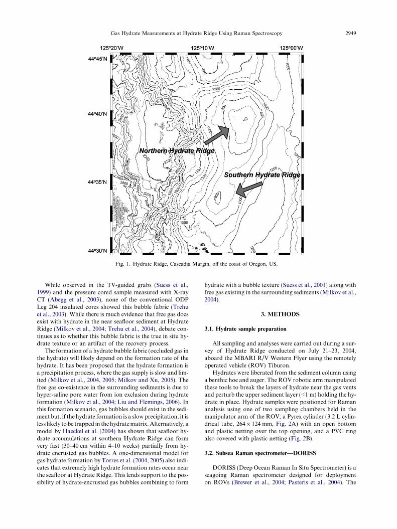
Fig. 1. Hydrate Ridge, Cascadia Margin, off the coast of Oregon, US.
Gas Hydrate Measurements at Hydrate Ridge Using Raman Spectroscopy 2949
While observed in the TV-guided grabs (Suess et al.,1999) and the pressure cored sample measured with X-rayCT (Abegg et al., 2003), none of the conventional ODPLeg 204 insulated cores showed this bubble fabric (Trehuet al., 2003). While there is much evidence that free gas doesexist with hydrate in the near seafloor sediment at HydrateRidge (Milkov et al., 2004; Trehu et al., 2004), debate con-tinues as to whether this bubble fabric is the true in situ hy-drate texture or an artifact of the recovery process.
The formation of a hydrate bubble fabric (occluded gas inthe hydrate) will likely depend on the formation rate of thehydrate. It has been proposed that the hydrate formation isa precipitation process, where the gas supply is slow and lim-ited (Milkov et al., 2004, 2005; Milkov and Xu, 2005). Thefree gas co-existence in the surrounding sediments is due tohyper-saline pore water from ion exclusion during hydrateformation (Milkov et al., 2004; Liu and Flemings, 2006). Inthis formation scenario, gas bubbles should exist in the sedi-ment but, if the hydrate formation is a slow precipitation, it isless likely to be trapped in the hydrate matrix. Alternatively, amodel by Haeckel et al. (2004) has shown that seafloor hy-drate accumulations at southern Hydrate Ridge can formvery fast (30–40 cm within 4–10 weeks) partially from hy-drate encrusted gas bubbles. A one-dimensional model forgas hydrate formation by Torres et al. (2004, 2005) also indi-cates that extremely high hydrate formation rates occur nearthe seafloor at Hydrate Ridge. This lends support to the pos-sibility of hydrate-encrusted gas bubbles combining to form
hydrate with a bubble texture (Suess et al., 2001) along withfree gas existing in the surrounding sediments (Milkov et al.,2004).
3. METHODS
3.1. Hydrate sample preparation
All sampling and analyses were carried out during a sur-vey of Hydrate Ridge conducted on July 21–23, 2004,aboard the MBARI R/V Western Flyer using the remotelyoperated vehicle (ROV) Tiburon.
Hydrates were liberated from the sediment column usinga benthic hoe and auger. The ROV robotic arm manipulatedthese tools to break the layers of hydrate near the gas ventsand perturb the upper sediment layer (<1 m) holding the hy-drate in place. Hydrate samples were positioned for Ramananalysis using one of two sampling chambers held in themanipulator arm of the ROV; a Pyrex cylinder (3.2 L cylin-drical tube, 264 · 124 mm, Fig. 2A) with an open bottomand plastic netting over the top opening, and a PVC ringalso covered with plastic netting (Fig. 2B).
3.2. Subsea Raman spectrometer—DORISS
DORISS (Deep Ocean Raman In Situ Spectrometer) is aseagoing Raman spectrometer designed for deploymenton ROVs (Brewer et al., 2004; Pasteris et al., 2004). The
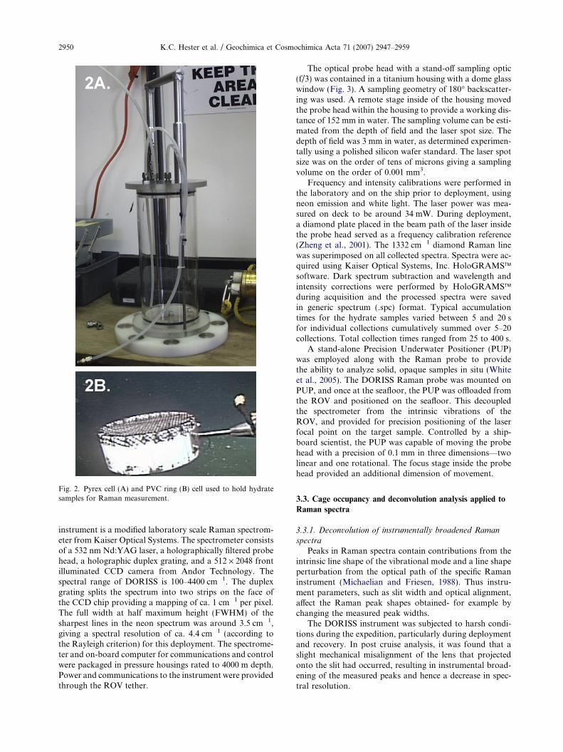
Fig. 2. Pyrex cell (A) and PVC ring (B) cell used to hold hydratesamples for Raman measurement.
2950 K.C. Hester et al. / Geochimica et Cosmochimica Acta 71 (2007) 2947–2959
instrument is a modified laboratory scale Raman spectrom-eter from Kaiser Optical Systems. The spectrometer consistsof a 532 nm Nd:YAG laser, a holographically filtered probehead, a holographic duplex grating, and a 512 · 2048 frontilluminated CCD camera from Andor Technology. Thespectral range of DORISS is 100–4400 cm�1. The duplexgrating splits the spectrum into two strips on the face ofthe CCD chip providing a mapping of ca. 1 cm�1 per pixel.The full width at half maximum height (FWHM) of thesharpest lines in the neon spectrum was around 3.5 cm�1,giving a spectral resolution of ca. 4.4 cm�1 (according tothe Rayleigh criterion) for this deployment. The spectrome-ter and on-board computer for communications and controlwere packaged in pressure housings rated to 4000 m depth.Power and communications to the instrument were providedthrough the ROV tether.
The optical probe head with a stand-off sampling optic(f/3) was contained in a titanium housing with a dome glasswindow (Fig. 3). A sampling geometry of 180� backscatter-ing was used. A remote stage inside of the housing movedthe probe head within the housing to provide a working dis-tance of 152 mm in water. The sampling volume can be esti-mated from the depth of field and the laser spot size. Thedepth of field was 3 mm in water, as determined experimen-tally using a polished silicon wafer standard. The laser spotsize was on the order of tens of microns giving a samplingvolume on the order of 0.001 mm3.
Frequency and intensity calibrations were performed inthe laboratory and on the ship prior to deployment, usingneon emission and white light. The laser power was mea-sured on deck to be around 34 mW. During deployment,a diamond plate placed in the beam path of the laser insidethe probe head served as a frequency calibration reference(Zheng et al., 2001). The 1332 cm�1 diamond Raman linewas superimposed on all collected spectra. Spectra were ac-quired using Kaiser Optical Systems, Inc. HoloGRAMS�software. Dark spectrum subtraction and wavelength andintensity corrections were performed by HoloGRAMS�during acquisition and the processed spectra were savedin generic spectrum (.spc) format. Typical accumulationtimes for the hydrate samples varied between 5 and 20 sfor individual collections cumulatively summed over 5–20collections. Total collection times ranged from 25 to 400 s.
A stand-alone Precision Underwater Positioner (PUP)was employed along with the Raman probe to providethe ability to analyze solid, opaque samples in situ (Whiteet al., 2005). The DORISS Raman probe was mounted onPUP, and once at the seafloor, the PUP was offloaded fromthe ROV and positioned on the seafloor. This decoupledthe spectrometer from the intrinsic vibrations of theROV, and provided for precision positioning of the laserfocal point on the target sample. Controlled by a ship-board scientist, the PUP was capable of moving the probehead with a precision of 0.1 mm in three dimensions—twolinear and one rotational. The focus stage inside the probehead provided an additional dimension of movement.
3.3. Cage occupancy and deconvolution analysis applied to
Raman spectra
3.3.1. Deconvolution of instrumentally broadened Raman
spectra
Peaks in Raman spectra contain contributions from theintrinsic line shape of the vibrational mode and a line shapeperturbation from the optical path of the specific Ramaninstrument (Michaelian and Friesen, 1988). Thus instru-ment parameters, such as slit width and optical alignment,affect the Raman peak shapes obtained- for example bychanging the measured peak widths.
The DORISS instrument was subjected to harsh condi-tions during the expedition, particularly during deploymentand recovery. In post cruise analysis, it was found that aslight mechanical misalignment of the lens that projectedonto the slit had occurred, resulting in instrumental broad-ening of the measured peaks and hence a decrease in spec-tral resolution.
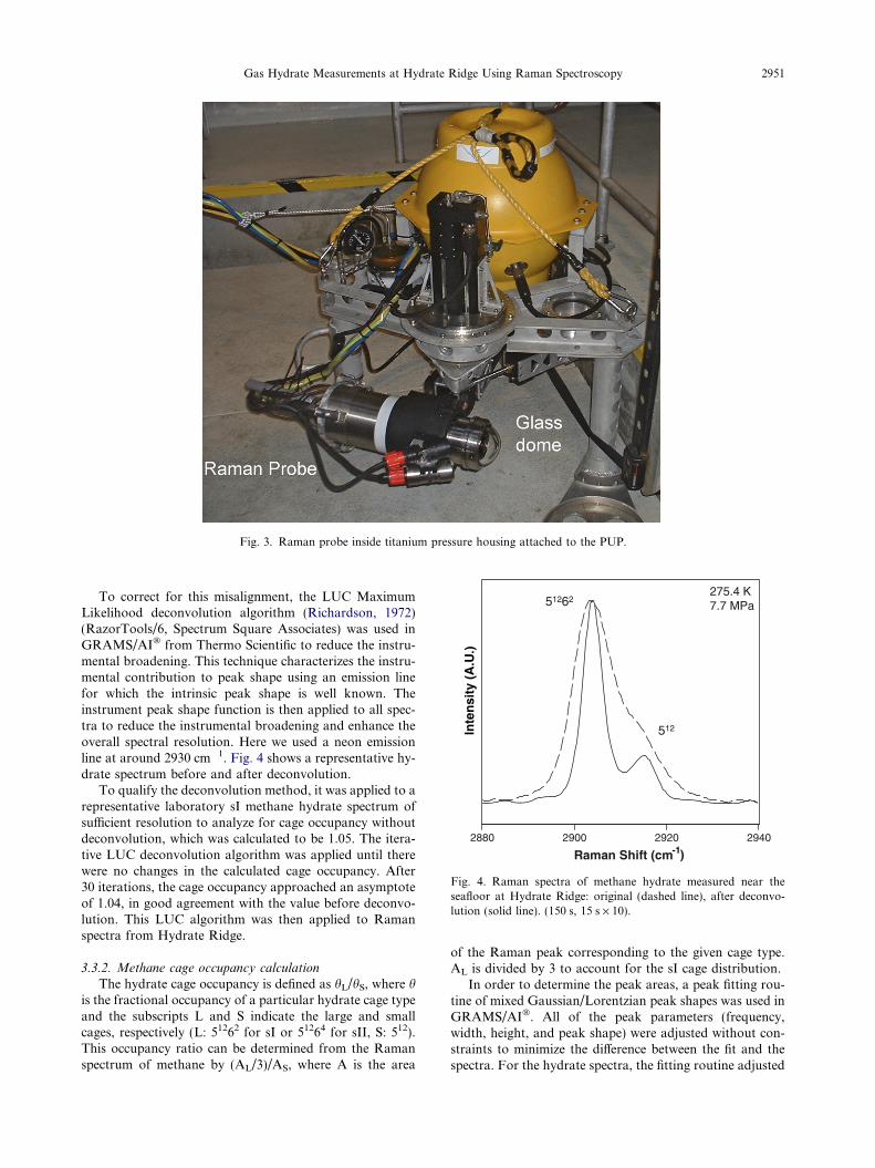
Fig. 3. Raman probe inside titanium pressure housing attached to the PUP.
0882 0092 0292 0492
)mc( tfihS namaR
5 21 62
5 21
K 4.572aPM 7.7
-1
Inte
nsi
ty (
A.U
.)
Fig. 4. Raman spectra of methane hydrate measured near theseafloor at Hydrate Ridge: original (dashed line), after deconvo-lution (solid line). (150 s, 15 s · 10).
Gas Hydrate Measurements at Hydrate Ridge Using Raman Spectroscopy 2951
To correct for this misalignment, the LUC MaximumLikelihood deconvolution algorithm (Richardson, 1972)(RazorTools/6, Spectrum Square Associates) was used inGRAMS/AI� from Thermo Scientific to reduce the instru-mental broadening. This technique characterizes the instru-mental contribution to peak shape using an emission linefor which the intrinsic peak shape is well known. Theinstrument peak shape function is then applied to all spec-tra to reduce the instrumental broadening and enhance theoverall spectral resolution. Here we used a neon emissionline at around 2930 cm�1. Fig. 4 shows a representative hy-drate spectrum before and after deconvolution.
To qualify the deconvolution method, it was applied to arepresentative laboratory sI methane hydrate spectrum ofsufficient resolution to analyze for cage occupancy withoutdeconvolution, which was calculated to be 1.05. The itera-tive LUC deconvolution algorithm was applied until therewere no changes in the calculated cage occupancy. After30 iterations, the cage occupancy approached an asymptoteof 1.04, in good agreement with the value before deconvo-lution. This LUC algorithm was then applied to Ramanspectra from Hydrate Ridge.
3.3.2. Methane cage occupancy calculation
The hydrate cage occupancy is defined as hL/hS, where his the fractional occupancy of a particular hydrate cage typeand the subscripts L and S indicate the large and smallcages, respectively (L: 51262 for sI or 51264 for sII, S: 512).This occupancy ratio can be determined from the Ramanspectrum of methane by (AL/3)/AS, where A is the area
of the Raman peak corresponding to the given cage type.AL is divided by 3 to account for the sI cage distribution.
In order to determine the peak areas, a peak fitting rou-tine of mixed Gaussian/Lorentzian peak shapes was used inGRAMS/AI�. All of the peak parameters (frequency,width, height, and peak shape) were adjusted without con-straints to minimize the difference between the fit and thespectra. For the hydrate spectra, the fitting routine adjusted
2952 K.C. Hester et al. / Geochimica et Cosmochimica Acta 71 (2007) 2947–2959
the peak parameters for two peaks in the CH-stretch regionto obtain the best fit to the data.
4. RESULTS AND DISCUSSION
4.1. Site observations
At Southern Hydrate Ridge (Fig. 1), two sites of activegas venting were located near the south summit at waterdepths of 770–780 m (T = 275.4 K, S = 34.52) by detectionof the bubble plume using the ROV mounted Simrad 1000sonar (330 kHz): site 1 (44� 34. 201’ N, 125� 8.794’ W) andsite 2 (44� 34.233’ N, 125� 8.886’ W). Hydrate deposits werefound in near surface sediments in close proximity to thegas vents at both sites. Upon perturbation, varying-sizedhydrate crystals (on the order of mm3 to cm3) could be ob-served floating up from the seafloor through the water col-umn due to the positive buoyancy of hydrate in seawater(Suess et al., 2001). The rising hydrate samples were thencaptured for Raman analysis in one of the sampling cham-bers. Similar to the observations of Suess et al. (2001), thepresence of free gas was inferred based on the highly vari-able rise rates of the hydrate samples.
A third site (44� 34.235’ N, 125� 8.900’ W) where activegas venting and hydrate deposits had been observed on aprevious survey in 2000 (Paull et al., 2002) was also visited.However, gas was no longer venting in this area and sea-floor hydrates were found to be scarce.
Along with the marked decrease in hydrate after gas vent-ing had ceased, the amount of hydrate liberated also de-creased with distance from the sites of active gas venting.Previous modeling of gas hydrate formations at southern Hy-drate Ridge indicated that restrictions can exist to gas migra-tion laterally away from vent sites. If only limited gas canmigrate laterally, the decreased amount of hydrate could beexpected compared to where the gas is being rapidly expelled.The observed decreasing quantity of seafloor hydrates awayfrom the venting sites appears to be in agreement with this lat-erally-limited gas migration model (Milkov et al., 2005).
At Northern Hydrate Ridge, there was one observed siteof active gas venting around visible deposits of carbonaterock. However, the amount of hydrate found when probingthe seafloor was insufficient to allow Raman measurementsto be made.
4.2. Raman measurements of hydrate
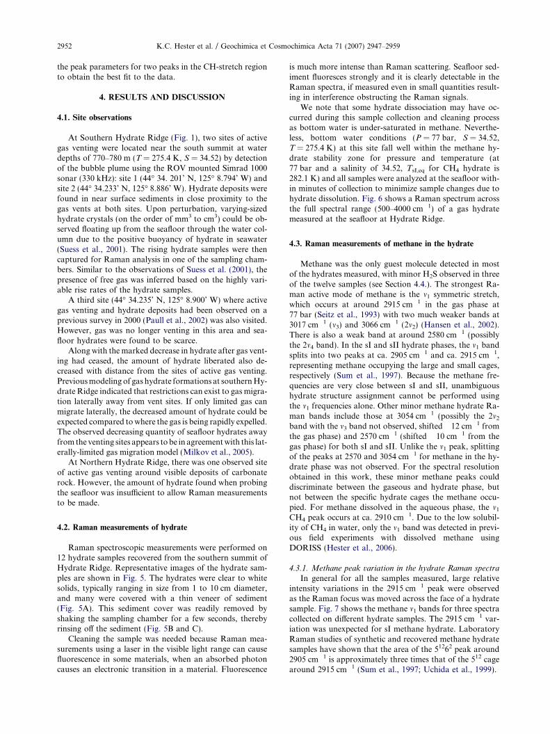
Raman spectroscopic measurements were performed on12 hydrate samples recovered from the southern summit ofHydrate Ridge. Representative images of the hydrate sam-ples are shown in Fig. 5. The hydrates were clear to whitesolids, typically ranging in size from 1 to 10 cm diameter,and many were covered with a thin veneer of sediment(Fig. 5A). This sediment cover was readily removed byshaking the sampling chamber for a few seconds, therebyrinsing off the sediment (Fig. 5B and C).
Cleaning the sample was needed because Raman mea-surements using a laser in the visible light range can causefluorescence in some materials, when an absorbed photoncauses an electronic transition in a material. Fluorescence
is much more intense than Raman scattering. Seafloor sed-iment fluoresces strongly and it is clearly detectable in theRaman spectra, if measured even in small quantities result-ing in interference obstructing the Raman signals.
We note that some hydrate dissociation may have oc-curred during this sample collection and cleaning processas bottom water is under-saturated in methane. Neverthe-less, bottom water conditions (P = 77 bar, S = 34.52,T = 275.4 K) at this site fall well within the methane hy-drate stability zone for pressure and temperature (at77 bar and a salinity of 34.52, TsI,eq for CH4 hydrate is282.1 K) and all samples were analyzed at the seafloor with-in minutes of collection to minimize sample changes due tohydrate dissolution. Fig. 6 shows a Raman spectrum acrossthe full spectral range (500–4000 cm�1) of a gas hydratemeasured at the seafloor at Hydrate Ridge.
4.3. Raman measurements of methane in the hydrate
Methane was the only guest molecule detected in mostof the hydrates measured, with minor H2S observed in threeof the twelve samples (see Section 4.4.). The strongest Ra-man active mode of methane is the m1 symmetric stretch,which occurs at around 2915 cm�1 in the gas phase at77 bar (Seitz et al., 1993) with two much weaker bands at3017 cm�1 (m3) and 3066 cm�1 (2m2) (Hansen et al., 2002).There is also a weak band at around 2580 cm�1 (possiblythe 2m4 band). In the sI and sII hydrate phases, the m1 bandsplits into two peaks at ca. 2905 cm�1 and ca. 2915 cm�1,representing methane occupying the large and small cages,respectively (Sum et al., 1997). Because the methane fre-quencies are very close between sI and sII, unambiguoushydrate structure assignment cannot be performed usingthe m1 frequencies alone. Other minor methane hydrate Ra-man bands include those at 3054 cm�1 (possibly the 2m2
band with the m3 band not observed, shifted �12 cm�1 fromthe gas phase) and 2570 cm�1 (shifted �10 cm�1 from thegas phase) for both sI and sII. Unlike the m1 peak, splittingof the peaks at 2570 and 3054 cm�1 for methane in the hy-drate phase was not observed. For the spectral resolutionobtained in this work, these minor methane peaks coulddiscriminate between the gaseous and hydrate phase, butnot between the specific hydrate cages the methane occu-pied. For methane dissolved in the aqueous phase, the m1
CH4 peak occurs at ca. 2910 cm�1. Due to the low solubil-ity of CH4 in water, only the m1 band was detected in previ-ous field experiments with dissolved methane usingDORISS (Hester et al., 2006).
4.3.1. Methane peak variation in the hydrate Raman spectra
In general for all the samples measured, large relativeintensity variations in the 2915 cm�1 peak were observedas the Raman focus was moved across the face of a hydratesample. Fig. 7 shows the methane m1 bands for three spectracollected on different hydrate samples. The 2915 cm�1 var-iation was unexpected for sI methane hydrate. LaboratoryRaman studies of synthetic and recovered methane hydratesamples have shown that the area of the 51262 peak around2905 cm�1 is approximately three times that of the 512 cagearound 2915 cm�1 (Sum et al., 1997; Uchida et al., 1999).
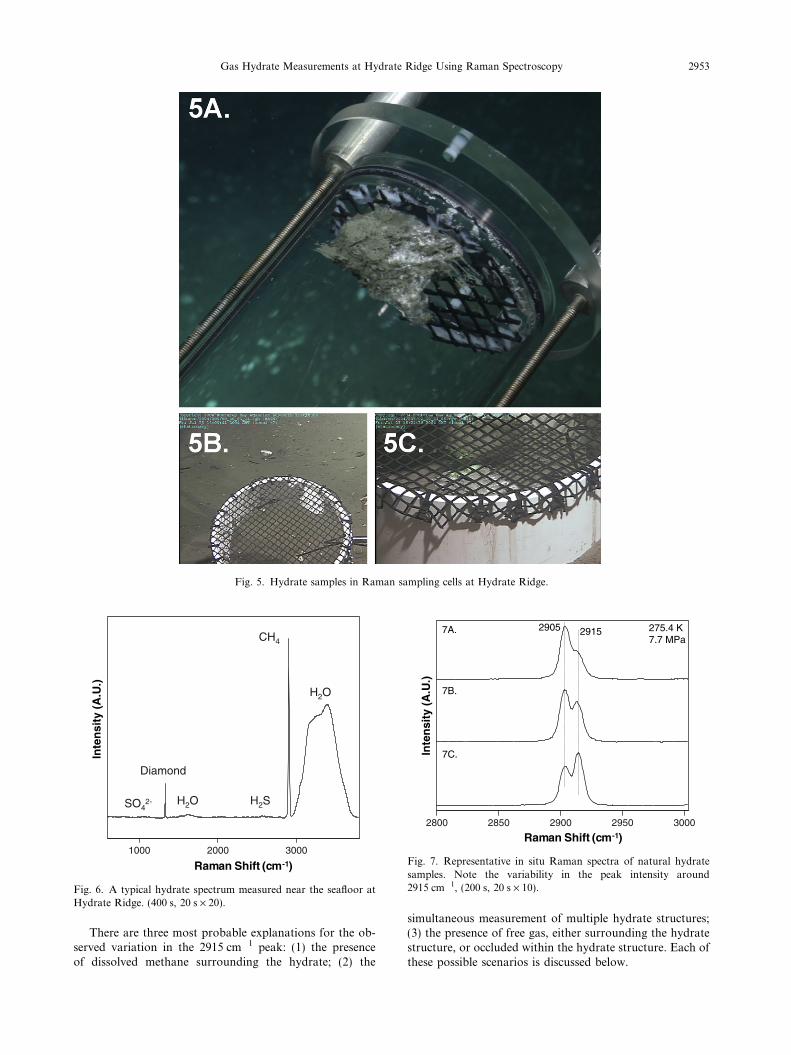
Fig. 5. Hydrate samples in Raman sampling cells at Hydrate Ridge.
0001 0002 0003
OS 4-2
dnomaiD
H2O
H2O
H2S
HC 4
mc(ShiftnamaR 1- )
Inte
nsi
ty (
A.U
.)
Fig. 6. A typical hydrate spectrum measured near the seafloor atHydrate Ridge. (400 s, 20 s · 20).
Inte
nsi
ty (
A.U
.)
0082 0582 0092 0592 0003
5092 5192 K 4.572aPM 7.7
.A7
.B7
.C7
mc(ShiftnamaR 1- )
Fig. 7. Representative in situ Raman spectra of natural hydratesamples. Note the variability in the peak intensity around2915 cm�1, (200 s, 20 s · 10).
Gas Hydrate Measurements at Hydrate Ridge Using Raman Spectroscopy 2953
There are three most probable explanations for the ob-served variation in the 2915 cm�1 peak: (1) the presenceof dissolved methane surrounding the hydrate; (2) the
simultaneous measurement of multiple hydrate structures;(3) the presence of free gas, either surrounding the hydratestructure, or occluded within the hydrate structure. Each ofthese possible scenarios is discussed below.
2954 K.C. Hester et al. / Geochimica et Cosmochimica Acta 71 (2007) 2947–2959
The removal of the hydrate from the sediment columnmay lead to some hydrate dissociation driven by methanedissolution into the under saturated seawater. While dis-solved methane could therefore be present in the surround-ing seawater, its low solubility in seawater at 770 m(0.002 g/cm3 for dissolved CH4 versus 0.1 g/cm3 for CH4
in the sI hydrate) strongly suggests that any dissolved meth-ane contribution to the spectra would be negligible. Thelow dissolved methane concentration in water leads to alow intensity Raman peak for dissolved methane in water(relative to hydrate) (Uchida et al., 2003). Additionally,the frequency of the dissolved CH4 m1 mode (around2910 cm�1 for the pressure/temperature conditions of theseexperiments), would likely contribute to both the 2905 and2915 cm�1 peaks. We therefore consider this explanationunlikely.
The second possibility for the 2915 cm1 peak variationcould be that multiple structures were present. Previouswork has shown small quantities of higher hydrocarbonspresent (e.g. C2H6, C3H8) in recovered hydrates from Hy-drate Ridge (Milkov et al., 2005), where these moleculescould result in sII formation. However, only methane andminor H2S (also a sI forming gas) were detected in the Ra-man spectra obtained in this study. While it can not be con-clusively determined that there was no coexistence ofmultiple structures, the absence of sII hydrate forming com-ponents from the spectra and, as will be discussed in thenext paragraph, minor bands of methane leads to the thirdpossibility (free gas) being the most likely explanation forthe measurements in this study.
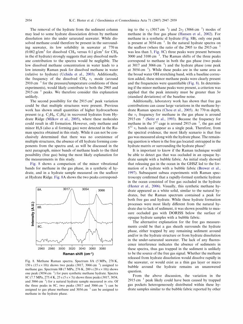
Fig. 8 shows a comparison of the minor vibrationalbands for methane in the gas phase, in a synthetic sI hy-drate, and in a hydrate sample measured on the seafloorat Hydrate Ridge. Fig. 8A shows the two peaks correspond-
0692 0892 0003 0203 0403 0603 0803
mc( Raman shift 1- )
Inte
nsi
ty (
A.U
.)
4503 6603.A8
.B8
.C8
7103
Fig. 8. Methane Raman spectra. Spectrum 8A (5 MPa, 278 K,150 s (15 s · 10)) shows two peaks (3017, 3066 cm�1) assigned tomethane gas. Spectrum 8B (7 MPa, 276 K, 200 s (20 s · 10)) showsone peak (3054 cm�1) for pure synthetic methane hydrate. Spectra8C (7.7 MPa, 275.4 K, 25 s (5 s · 5)) shows three peaks (3017, 3054,and 3066 cm�1) for a natural hydrate sample measured in situ. Ofthe three peaks in 8C, two peaks (3017 and 3066 cm�1) can beassigned to gas phase methane and 3054 cm�1 can be assigned tomethane in the hydrate phase.
ing to the m3 (3017 cm�1) and 2m2 (3066 cm�1) modes ofmethane in the free gas phase (Hansen et al., 2002). Formethane in a synthetic sI hydrate (Fig. 8B), only one peakis present at 3054 cm�1. In the natural hydrate spectra onthe seafloor (where the ratio of the 2905 to the 2915 cm�1
was less than 3, Fig. 8C) three peaks were present between3000 and 3100 cm�1. The Raman shifts of the three peakscorrespond to methane in both the gas phase (two peaksat 3017 and 3066 cm�1) and the hydrate phase (one peakat 3054 cm�1). While these peaks are in the same area asthe broad water OH stretching band, with a baseline correc-tion added, these minor methane peaks were clearly presentand the frequencies were quantifiable (Fig. 8). In determin-ing if the minor methane peaks were present, a criterion wasapplied that the peak intensity must be greater than 3r(standard deviations) of the baseline noise.
Additionally, laboratory work has shown that free gascontributions can cause large variations in the methane hy-drate Raman spectra (Chou et al., 2005). At 770 m depth,the m1 frequency for methane in the gas phase is around2915 cm�1 (Seitz et al., 1993). Because the frequency formethane in the 512 cage is around 2915 cm�1, the gas and512 m1 bands can appear as a single peak. Therefore, fromthe spectral evidence, the most likely scenario is that freegas was measured along with the hydrate phase. The remain-ing question is where is the free gas located: entrapped in thehydrate matrix or surrounding the hydrate phase?
It is important to know if the Raman technique wouldbe able to detect gas that was occluded in an opaque hy-drate sample with a bubble fabric. An initial study showedthat releasing gas in the ocean in the GHSZ led to the for-mation of a hydrate with a bubble fabric (Brewer et al.,1997). Subsequent subsea experiments with Raman spec-troscopy confirmed that a rapidly-formed synthetic hydratein the ocean consisted of free gas occluded in the hydrate(Hester et al., 2006). Visually, this synthetic methane hy-drate appeared as a white solid, similar to the natural hy-drates, but the Raman spectrum contained a peak forboth free gas and hydrate. While these hydrate formationprocesses were most likely different from the natural hy-drate due to lack of sediment, it was shown possible to mea-sure occluded gas with DORISS below the surface ofopaque hydrate samples with a bubble fabric.
The alternative explanation for the free gas measure-ments could be that a gas sheath surrounds the hydratephase, either trapped by any remaining sediment aroundand/or in the hydrate structure or from hydrate dissolutionin the under-saturated seawater. The lack of any fluores-cence interference indicates the absence of sediments inthese spectra, thus gas trapped in the sediment is unlikelyto be the source of the free gas signal. Whether the methanereleased from hydrate dissolution would dissolve rapidly inthe seawater, or would exist as a thin gas layer or microbubble around the hydrate remains an unansweredquestion.
From the above discussion, the variation in the2915 cm�1 peak likely could have been caused by trappedgas pockets heterogeneously distributed within these hy-drate samples similar to the bubble fabric reported by other
0752
5952
K 4.572aPM 7.7
Inte
nsi
ty (
A.U
.)
Gas Hydrate Measurements at Hydrate Ridge Using Raman Spectroscopy 2955
researchers (Suess et al., 2002; Abegg et al., 2003) and/ormicro bubbles of methane present on the hydrate surface.
4.3.2. Methane hydrate occupancy ratios
Hydrate occupancy ratios are a measure of the distribu-tion of guest filling in the hydrate cages. Because methane ispresent in both cages of the sI hydrate with distinct m1 peakpositions, the peak areas can be integrated to obtain theoccupancy ratio of the hydrate (Section 3.3.2). The occu-pancy ratio determined from Raman has been shown quan-titative for pure methane hydrate (Subramanian, 2000;Wilson et al., 2002).
Due to the overlap between the Raman peak for meth-ane in the gas phase and in the 512 cage, cage occupancieswere calculated only for the samples with minimal gas con-tribution. This was determined by the absence of the minormethane gas phase peaks at 3017 and 3066 cm�1, as de-scribed in Section 4.3.1. The minor methane peak at2570 cm�1 for gas or 2580 cm�1 for hydrate could also beused to determine if gas was contributing to a Raman spec-trum of hydrate. However, the methane peak at 2570–2580 cm�1 was weaker than the 2m2 and m3 peaks and notresolvable in every spectrum. Samples with a significantamount of gas contribution were not analyzed for cageoccupancy because small changes in the gaseous methanem1 peak width during peak-fitting caused large variationsin the calculated methane cage occupancy ratios. It wasthen assumed that only the sI and gas phases of methanewere present, where all bands from 2900 to 2920 cm�1 areassigned to the m1 modes of these phases. In a natural sys-tem, it is impossible to completely eliminate the possibilityof other contributions to the Raman spectra. However, asdiscussed in Section 4.3.1, limiting the analysis to methanecontributions from the sI hydrate and gaseous phase isreasonable.
The results of the methane cage occupancy analysis aregiven in Table 1. As seen in the table, the occupancy ratiofor methane varies between 1.01 and 1.30. These numbersare in the same range as occupancies determined from lab-oratory studies of methane hydrates (1.01–1.27), includingboth synthetic and recovered natural samples (Sum et al.,1997; Ripmeester and Ratcliffe, 1998; Uchida et al., 1999,2005; Huo et al., 2003; Lu et al., 2005; Ripmeester et al.,2005). The cage occupancy number shows that for methanein the sI hydrate, a larger fraction of the large cages arefilled with methane compared to the small cages, in agree-ment with the above previous observations of laboratorysynthesized and recovered natural hydrate samples. If fulllarge cage occupancy was assumed, the hydration number
Table 1Methane occupancy ratios for hydrates measured in situ at HydrateRidge
Dive No. Location hL/hS
TD699 Hydrate Ridge, Site 1 1.28TD699 Hydrate Ridge, Site 1 1.30TD702 Hydrate Ridge, Site 1 1.03TD702 Hydrate Ridge, Site 1 1.01TD699 Hydrate Ridge, Site 2 1.13
would range from 5.8 to 6.1, in agreement with a rigorousstudy of the methane hydrate hydration number (molar ra-tio of water to guest molecules in the hydrate) at variousconditions (Circone et al., 2005).
4.4. Presence of other gases in the hydrate
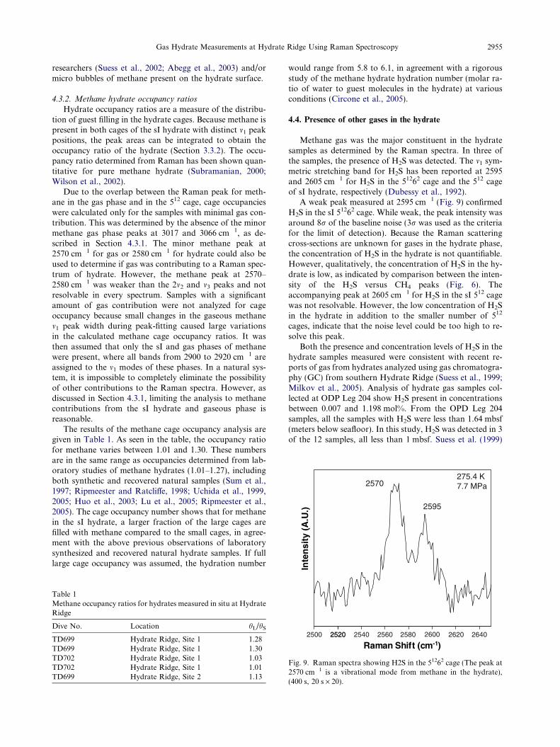
Methane gas was the major constituent in the hydratesamples as determined by the Raman spectra. In three ofthe samples, the presence of H2S was detected. The m1 sym-metric stretching band for H2S has been reported at 2595and 2605 cm�1 for H2S in the 51262 cage and the 512 cageof sI hydrate, respectively (Dubessy et al., 1992).
A weak peak measured at 2595 cm�1 (Fig. 9) confirmedH2S in the sI 51262 cage. While weak, the peak intensity wasaround 8r of the baseline noise (3r was used as the criteriafor the limit of detection). Because the Raman scatteringcross-sections are unknown for gases in the hydrate phase,the concentration of H2S in the hydrate is not quantifiable.However, qualitatively, the concentration of H2S in the hy-drate is low, as indicated by comparison between the inten-sity of the H2S versus CH4 peaks (Fig. 6). Theaccompanying peak at 2605 cm�1 for H2S in the sI 512 cagewas not resolvable. However, the low concentration of H2Sin the hydrate in addition to the smaller number of 512
cages, indicate that the noise level could be too high to re-solve this peak.
Both the presence and concentration levels of H2S in thehydrate samples measured were consistent with recent re-ports of gas from hydrates analyzed using gas chromatogra-phy (GC) from southern Hydrate Ridge (Suess et al., 1999;Milkov et al., 2005). Analysis of hydrate gas samples col-lected at ODP Leg 204 show H2S present in concentrationsbetween 0.007 and 1.198 mol%. From the OPD Leg 204samples, all the samples with H2S were less than 1.64 mbsf(meters below seafloor). In this study, H2S was detected in 3of the 12 samples, all less than 1 mbsf. Suess et al. (1999)
0052 0252 0252 0452 0652 0852 0062 0262 0462
mc(tfihSnamaR 1- )
Fig. 9. Raman spectra showing H2S in the 51262 cage (The peak at2570 cm�1 is a vibrational mode from methane in the hydrate),(400 s, 20 s · 20).
2956 K.C. Hester et al. / Geochimica et Cosmochimica Acta 71 (2007) 2947–2959
found H2S present in hydrates less than 6 mbsf in concen-trations between 1.49 and 3.07 mol%.
While H2S was measured, unlike the previous GC mea-surements, no CO2 or hydrocarbon components other thanmethane were detected. However, we cannot conclude theywere not present in small concentrations. Because this wasof the first field deployment of the DORISS system to mea-sure a natural hydrate system, we were unable to estimatethe lowest detectable concentrations of various gas compo-nents from this work. Recent work using DORISS in situ at500 m water depth has shown the limit of detection for CO2
in the aqueous phase was 10 mmol/kg (Dunk et al., 2005).
4.5. Water contribution to the Raman spectra
The focus of most Raman studies on hydrates has beenon the guest molecules. In addition to the Raman signal forthe hydrate guest molecules, the Raman signal for the hostwater cages is also present. This water band can also beused to differentiate between the liquid water and hydratephase. The water stretching modes combine to appear asa broad spectral feature. Although it appears to be onepeak, this spectral region will be referred to as the waterO–H stretching Raman bands.
0082 0003 0023 0043 0063 0083
mc( tfihS namaR 1- )
Inte
nsi
ty (
A.U
.)
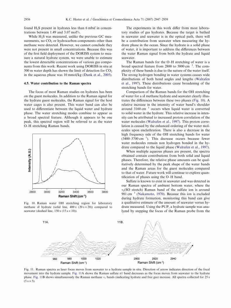
Fig. 10. Raman water OH stretching region for laboratorymethane sI hydrate (solid line, 400 s (20 s · 20)) compared toseawater (dashed line, 150 s (15 s · 10)).
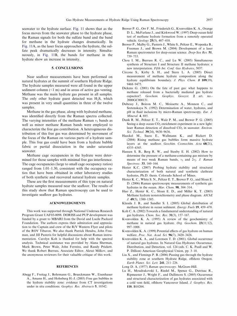
Fig. 11. Raman spectra as laser focus moves from seawater to a hydratemovement into the hydrate sample. Fig. 11A shows the Raman sulfate nphase. Fig. 11B shows simultaneously the Raman methane m1 bands (ind(5 s · 5).
The experiments in this work differ from most labora-tory studies of gas hydrates. Because the target is bathedin seawater and seawater is in the optical path, there willbe a contribution from seawater when measuring the hy-drate phase in the ocean. Since the hydrate is a solid phaseof water, it is important to address the differences betweenthe water Raman signal from both the hydrate and liquidseawater.
The Raman bands for the O–H stretching of water is abroad spectral feature from 2800 to 3800 cm�1. The com-plexity of these bands is due to the nature of the water itself.The strong hydrogen bonding in water systems causes widedistributions of both bond angles and lengths (Walrafenet al., 1997). These distributions cause broadening of thestretching bands for water.
Comparison of the Raman bands for the OH stretchingof water for a sI methane hydrate and seawater clearly illus-trates the differences between these two phases (Fig. 10). Arelative increase in the intensity of water band’s shoulderaround 3160 cm�1 occurs when liquid water is convertedto solid water in the hydrate. This relative increase in inten-sity can be attributed to increased proton correlation of thewater molecules (Walrafen et al., 1997). This proton corre-lation is caused by the enhanced ordering of the water mol-ecules upon enclathration. There is also a decrease in thehigh frequency side of the OH stretching bands for water(3400–3700 cm�1). This decrease occurs because fewerwater molecules remain non hydrogen bonded in the hy-drate compared to the liquid phase (Walrafen et al., 1997).
When multiple aqueous phases are present, the spectraobtained contain contributions from both solid and liquidphases. Therefore, the relative phase amounts can be qual-itatively determined by the peak shape of the water bandsand the Raman areas for the guest molecules comparedto that of water. Future work will continue to explore quan-tification of phases using the O–H band.
Sulfate is known to exist in seawater and was detected inour Raman spectra of ambient bottom water, where them1(SO stretch) Raman band of the sulfate ion is around981 cm�1 (Nakamoto, 1970). Because this ion is excludedduring hydrate formation, monitoring this band can givea qualitative estimate of the amount of seawater versus hy-drate measured. Using the PUP, a hydrate sample was ana-lyzed by stepping the focus of the Raman probe from the
sample in situ. Direction of arrow indicates direction of the focal1 band decreases as the focus moves from seawater to the hydrateicating hydrate and free gas) increase. All spectra collected for 25 s
Gas Hydrate Measurements at Hydrate Ridge Using Raman Spectroscopy 2957
seawater to the hydrate surface. Fig. 11 shows that as thefocus moves from the seawater phase to the hydrate phase,the Raman signals for both the sulfate band and the bandfor methane in the hydrate changes dramatically. InFig. 11A, as the laser focus approaches the hydrate, the sul-fate peak dramatically decreases in intensity. Simulta-neously, in Fig. 11B, the bands for methane in thehydrate show an increase in intensity.
5. CONCLUSIONS
Near seafloor measurements have been performed onnatural hydrates at the summit of southern Hydrate Ridge.The hydrate samples measured were all found in the uppersediment column (<1 m) and in areas of active gas venting.Methane was the main hydrate gas present in all samples.The only other hydrate guest detected was H2S, whichwas present in very small quantities in three of the twelvesamples.
Methane in the gas phase, along with hydrated methane,was identified directly from the Raman spectra collected.The varying intensities of the methane Raman m1 bands aswell as minor methane Raman bands were employed tocharacterize the free gas contribution. A heterogeneous dis-tribution of this free gas was determined by movement ofthe focus of the Raman on various parts of a hydrate sam-ple. This free gas could have been from a hydrate bubblefabric or partial dissociation in the under saturatedseawater.
Methane cage occupancies in the hydrate were deter-mined for those samples with minimal free gas interference.The cage occupancies (large to small cage occupancy ratios)ranged from 1.01–1.30, consistent with the occupancy ra-tios that have been obtained in other laboratory studiesof both synthetic and recovered natural hydrate samples.
These are the first measurements of this type on naturalhydrate samples measured near the seafloor. The results ofthis study show that Raman spectroscopy can be used toinvestigate seafloor gas hydrates.
ACKNOWLEDGMENTS
This work was supported through National Undersea ResearchProgram Grant UAF03-0098. DORISS and PUP development wasfunded by a grant to MBARI from the David and Lucile PackardFoundation. The authors express their admiration and apprecia-tion to the Captain and crew of the R/V Western Flyer and pilotsof the ROV Tiburon. We also thank Patrick Hendra, John Free-man, and Jill Pasteris for helpful discussions about Raman instru-mentation. Carolyn Koh is thanked for help with the spectralanalysis. Technical assistance was provided by Alana Sherman,Mark Brown, Peter Walz, John Ferreira, and Randy Prickett.We thank Robert Burruss, Associate Editor, Alexei Milkov, andthe anonymous reviewers for their valuable critique of this work.
REFERENCES
Abegg F., Freitag J., Bohrmann G., Brueckmann W., EisenhauerA., Amann H., and Hohnberg H.-J. (2003) Free gas bubbles inthe hydrate stability zone: evidence from CT investigationsunder in situ conditions. Geophys. Res. Abstracts 5, 10342.
Brewer P. G., Orr F. M., Friederich G., Kvenvolden K. A., OrangeD. L., McFarlane J., and Kirkwood W. (1997) Deep-ocean fieldtest of methane hydrate formation from a remotely operatedvehicle. Geology 25(5), 407–410.
Brewer P., Malby G., Pasteris J., White S., Peltzer E., Wopenka B.,Freeman J., and Brown M. (2004) Development of a laserRaman spectrometer for deep-ocean science. Deep-Sea Res. 51,
739–753.
Chou I. M., Burruss R. C., and Lu W. (2005) Simultaneoussynthesis of Structure I and Structure II methane hydrates: anew interpretation. Fifth Int. Conf. Gas Hydrates, 5037.
Circone S., Kirby S. H., and Stern L. A. (2005) Directmeasurement of methane hydrate composition along thehydrate equilibrium boundary. J. Phys. Chem. B 109(19),
9468–9475.
Dickens G. (2001) On the fate of past gas: what happens tomethane released from a bacterially mediated gas hydratecapacitor?. Geochem. Geophys. Geosyst. 2 art. no.-
2000GC000131.
Dubessy J., Boiron M. C., Moissette A., Monnon C., andSretenskaya N. (1992) Determination of water, hydrates, andpH in fluid inclusions by micro-Raman spectroscopy. Eur. J.
Mineral. 4, 885.
Dunk R. M., Peltzer E. T., Walz P. M., and Brewer P. G. (2005)Seeing a deep ocean CO2 enrichment experiment in a new light:laser Raman detection of dissolved CO2 in seawater. Environ.
Sci. Technol. 39(24), 9630–9636.
Haeckel M., Suess E., Wallmann K., and Rickert D.(2004) Rising methane gas bubbles form massive hydratelayers at the seafloor. Geochim. Cosmochim. Acta 68(21),
4335–4345.
Hansen S. B., Berg R. W., and Stenby E. H. (2002) How todetermine the pressure of a methane-containing gas mixture bymeans of two weak Raman bands, m3 and 2m2. J. Raman
Spectrosc. 33, 160–164.
Hester K.C. (2007) Probing hydrate stability and structuralcharacterization of both natural and synthetic clathratehydrates, Ph.D. thesis. Colorado School of Mines.
Hester K. C., White S. N., Peltzer E. T., Brewer P. G., and Sloan E.D. (2006) Raman spectroscopic measurements of synthetic gashydrates in the ocean. Mar. Chem. 98, 304–314.
Huo Z., Hester K. C., Sloan E. D., and Miller K. T. (2003)Methane hydrate nonstoichiometry and phase diagram. AIChE
J. 49(5), 1300–1305.
Klauda J. B., and Sandler S. I. (2005) Global distribution ofmethane hydrate in ocean sediment. Energy Fuels 19, 459–470.
Koh C. A. (2002) Towards a fundamental understanding of naturalgas hydrates. Chem. Soc. Rev. 31(3), 157–167.
Kvenvolden K. A. (1995) A review of the geochemistry ofmethane in natural gas hydrate. Org. Geochem. 23(11/12),
997–1008.
Kvenvolden K. A. (1999) Potential effects of gas hydrate on humanwelfare. Proc. Nat. Acad. Sci. 96(7), 3420–3426.
Kvenvolden K. A., and Lorensen T. D. (2001). Global occurrenceof natural gas hydrates. In Natural Gas Hydrates: Occurrence,Distribution, and Detection, vol. 124 (eds. C. K. Paull and W.P. Dillion) American Geophysical Union, pp. 3–18.
Liu X., and Flemings P. B. (2006) Passing gas through the hydratestability zone at southern Hydrate Ridge, offshore Oregon.Earth Planet. Sci. Lett. 241, 211–226.
Long D. A. (1977) Raman spectroscopy. McGraw-Hill.Lu H., Moudrakovski I., Riedel M., Spence G., Dutrisac R.,
Ripmeester J., Wright F., and Dallimore S. (2005) Occurrenceand structural characterization of gas hydrates associated witha cold vent field, offshore Vancouver Island. J. Geophys. Res.
110, B10204.
2958 K.C. Hester et al. / Geochimica et Cosmochimica Acta 71 (2007) 2947–2959
Lu H., Seo Y., Lee J., Moudrakovski I., Ripmeester J. A.,Chapman N. R., Coffin R. B., Gardner G., and Pohlman J.(2007) Complex gas hydrate from the Cascadia margin. Nature
445, 303–306.
Michaelian K. H., and Friesen W. I. (1988) Deconvolution ofinstrumental broadening in dispersive Raman spectroscopy.Appl. Spectrosc. 42(8), 1538–1543.
Milkov A. V. (2004) Global estimates of hydrate-bound gas inmarine sediments: how much is really out there? Earth-Sci. Rev.
66, 193–197.
Milkov A. V. (2005) Molecular and stable isotope composition ofnatural gas hydrates: a revised global dataset and basicinterpretations in the context of geological settings. Org.
Geochem. 36(5), 681–702.
Milkov A. V., and Xu W. (2005) Comment on ‘‘Gas hydrategrowth, methane transport, and chloride enrichment at thesouthern summit of Hydrate Ridge, Cascadia Margin offOregon’’ by Torres et al. [Earth Planet. Sci. Lett. 226 (2004)225–241]. Earth Planet. Sci. Lett. 239, 162–167.
Milkov A. V., Claypool G. E., Lee Y.-J., Dickens G. R., Xu W.,and Borowski W. S.and the ODP Leg 204 Scientific Party(2003) In situ methane concentrations at Hydrate Ridgeoffshore Oregon: new constraints on the global gas hydrateinventory from an active margin. Geology 31, 833–836.
Milkov A. V., Dickens G. R., Claypool G. E., Lee Y.-J., BorowskiW. S., Torres M. E., Xu W., Tomaru K., Trehu A. M., andSchultheiss P. (2004) Co-existence of gas hydrate, free gas, andbrine within the regional gas hydrate stability zone at thesouthern summit of Hydrate Ridge (Oregon margin): evidencefrom prolonged degassing of a pressurized core. Earth Planet.
Sci. Lett. 222(3-4), 829–843.
Milkov A. V., Claypool G. E., Lee Y., and Sassen R. (2005) Gashydrate systems at Hydrate Ridge offshore Oregon inferredfrom molecular and isotopic properties of hydrate-bound andvoid gases. Geochim. Cosmochim. Acta 69(4), 1007–1026.
Nakamoto K. (1970) Infrared spectra of inorganic and coordination
compounds. Wiley-Interscience.Pasteris J. D., Wopenka B., Freeman J. J., Brewer P. G., White S.
N., Peltzer E. T., and Malby G. (2004) Spectroscopic successand challenges: Raman spectroscopy at 3.6 km depth in theocean. Appl. Spectrosc. 58(7), 195A–208A.
Paull C. K., Brewer P. G., Ussler W., Peltzer E. T., Rehder G., andClague D. (2002) Evaluation of marine slumping as a mecha-nism to transfer methane from seafloor gas hydrate depositsinto the upper ocean and atmosphere. Fourth Int.Conf. Gas
Hydrates, 31–35.Pohlman J. W., Canuel E. A., Chapman N. R., Spence G. D.,
Whiticar M. J., and Coffin R. D. (2005) The origin of thermogenicgas hydrates on the northern Cascadia Margin as inferred fromisotopic (13C/12C and D/H) and molecular composition ofhydrate and vent gas. Org. Geochem. 36, 703–716.
Richardson W. H. (1972) Bayesian iterative method of imagerestoration. J. Optical Soc. Am. 62, 55–59.
Ripmeester J. A., and Ratcliffe C. I. (1998) The diverse nature ofdodecahedral cages in clathrate hydrates as revealed by 129Xeand 13C NMR spectroscopy: CO2 as a small-cage guest. Energy
Fuels 12(2), 197–200.
Ripmeester J. A., Tse J. S., Ratcliffe C. I., and Powell B. M. (1987)A new clathrate hydrate structure. Nature 325, 135–136.
Ripmeester J. A., Lu H., Moudrakovski I. L., Dutrisac R., WilsonL. D., Wright F., and Dallimore S. R. (2005) Structure andcomposition of gas hydrate in sediment recovered from theJAPEX/JNOC/GSC et al. Mallik 5L-38 gas hydrate productionresearch well, determined by X-ray diffraction and Raman andsolid-state nuclear magnetic resonance spectroscopy. GSC Bull.
585, 6.
Sassen R., and MacDonald I. R. (1994) Evidence of Structure Hhydrate, Gulf of Mexico continental slope. Org. Geochem.
22(6), 1029–1032.
Seitz J. C., Pasteris J. D., and Wopenka B. (1987) Characterizationof CO2–CH4–H2O fluid inclusions by microthermometry andlaser Raman microprobe spectroscopy: inferences for clathrateand fluid equilibria. Geochim. Cosmochim. Acta 51(6), 1651–
1664.
Seitz J., Pasteris J., and Chou I. (1993) Raman spectroscopiccharacterization of gas mixtures. I. Quantitative compositionand pressure determines of CH4, N2, and their mixtures. Am. J.
Sci. 293, 297–321.
Seitz J. C., Pasteris J., and Chou I. M. (1996) Raman spectroscopiccharacterization of gas mixtures II. Quantitative compositionand pressure determination of the CO2–CH4 system. Am. J. Sci.
296, 577–600.
Sloan E. D. (1998) Clathrate hydrates of natural gases, second ed.Marcel Dekker.
Subramanian, S. (2000) Measurements of Clathrate HydratesContaining Methane and Ethane Using Raman Spectroscopy.Ph.D. thesis, Colorado School of Mines.
Suess E., Torres M. E., Bohrmann G., Collier R. W., and GreinertJ. (1999) Gas hydrate destabilization: enhanced dewatering,benthic material turnover and large methane plumes at theCascadia convergent margin. Earth Planet. Sci. Lett. 170, 1–15.
Suess E., Torres M. E., Bohrmann G., and Collier R. W. (2001) Seafloor methane hydrates at Hydrate Ridge, Cascadia Margin. InNatural Gas Hydrates: Occurrence, Distribution, and Detec-tion, vol. 124 (eds. C. K. Paull and W. P. Dillion). AmericanGeophysical Union, pp. 87–98.
Suess E., Bohrmann G., Rickert D., Kuhs W. F., Torres M. E.,Trehu A., and Linke P. (2002) Properties and fabric of near-surface methane hydrates at Hydrate Ridge, Cascadia Margin.Fourth Int. Conf. Gas Hydrates, 740–744.
Sum A. K., Burruss R. C., and Sloan E. D. (1997) Measurement ofclathrate hydrates via Raman spectroscopy. J. Phys. Chem. B
101(38), 7371–7377.
Torres M. E., Wallmann K., Trehu A. M., Bohrmann G.,Borowski W. S., and Tomaru H. (2004) Gas hydrate growth,methane transport, and chloride enrichment at the southernsummit of Hydrate Ridge, Cascadia Margin off Oregon. Earth
Planet. Sci. Lett. 226, 225–241.
Torres M. E., Wallmann K., Trehu A. M., Bohrmann G.,Borowski W. S., and Tomaru H. (2005) Reply to commenton: ‘‘Gas hydrate growth, methane transport, and chlorideenrichment at the southern summit of Hydrate Ridge, CascadiaMargin off Oregon. Earth Planet. Sci. Lett. 239, 168–175.
Trehu, A. M., Bohrmann, G., Rack, R. F., and Torres, M. E.,et al. (2003) Proceedings of the Ocean Drill. Program, InitialReport 204. Available from: Ocean Drilling Program, TexasA&M University, College Station TX 77845-9547, USA [CD-ROM].
Trehu A. M., Flemings P. B., Bangs N. L., Chevallier J., Gracia E.,Johnson J. E., Liu C.-S., Liu X., Riedel M., and Torres M. E.(2004) Feeding methane vents and gas hydrate deposits at southHydrate Ridge. Geophys. Res. Lett. 31, L23310.
Tulk C., Ripmeester J., and Klug D. (2000) The application ofRaman spectroscopy to the study of gas hydrates. Ann. N.Y.
Acad. Sci. 912, 859.
Tyron M. D., Brown K. M., and Torres M. E. (2002) Fluid andchemical flux in and out of sediments hosting methane hydratedeposits on Hydrate Ridge, OR, II: hydrological processes.Earth Planet. Sci. Lett. 201, 541–557.
Uchida T., Hirano T., Ebinuma T., Narita H., Gohara K., andMae S. (1999) Raman spectroscopic determination of hydrationnumber of methane hydrates. AIChE J. 45(12), 2641–2645.
Gas Hydrate Measurements at Hydrate Ridge Using Raman Spectroscopy 2959
Uchida T., Takeya S., Wilson L. D., Tulk C. A., Ripmeester J.A., Nagao J., Ebinuma T., and Narita H. (2003) Measure-ments of physical properties of gas hydrates and in situobservations of formation and decomposition processes viaRaman spectroscopy and X-ray diffraction. Can. J. Phys. 81,
351–357.
Uchida T., Uchida T., Kato A., Sasaki H., Kono F., and Takeya S.(2005) Physical properties of natural gas hydrate and associatedgas-hydrate-bearing sediments in the JAPEX/JNOC/GSC et al.Mallik 5L-38 gas hydrate production research well. GSC Bull.
585, 10.
Walrafen, G. E., Yang, W. H., and Chu, Y. C. (1997) Ramanevidence for the clathrate-like structure of highly super cooledwater. In Supercooled Liquids, vol. 21 (ACS Symposium Series676), pp. 287–308.
Westbrook, G. K., Carson, B., Musgrave, R. J., and Suess, E.(1994) Proceedings of the Ocean Drilling Program, InitialReports 146, Ocean Drilling Program, p. 477.
White S. N., Kirkwood W. J., Sherman A. D., Brown M. O.,Henthorn R., Salamy K. A., Walz P. M., Peltzer E. T., andBrewer P. G. (2005) Development and deployment of a precisionunderwater positioning system for in situ laser Raman spectros-copy in the deep ocean. Deep Sea Res. I. 52(12), 2376–2386.
White S. N., Dunk R. M., Peltzer E. T., Freeman J. J., and BrewerP. G. (2006) In situ Raman analyses of deep-sea hydrothermaland cold seep systems (Gorda Ridge and Hydrate Ridge).Geochem. Geophys. Geosyst. 7, Q05023.
Wilson L. D., Tulk C. A., and Ripmeester J. A. (2002) Instru-mental techniques for the investigation of methane hydrates:cross-calibrating NMR and Raman spectroscopic data. Fourth
Int. Conf. Gas Hydrates, 614–618.Zheng X., Fu W., Albin S., Wise K. L., Javey A., and Cooper J. B.
(2001) Self-referencing Raman probes for quantitative analysis.Appl. Spectrosc. 55(4), 382–388.
Associate editor: Robert C. Burruss