Embed Size (px)
Citation preview
M30
*9003943*
9003943Rev. 09 (12-2012)
(Gas/LPG)
Scrubber--SweeperOperator Manual
The Safe Scrubbing AlternativeR
ESR Extended Scrub SystemTennantTrueR Parts
HygenicR Fully Cleanable TanksFloorSmartt Integrated Cleaning System
IRISt a Tennant Technology
North America / InternationalTo view, print or downloadthe latest manual, visit:
www.tennantco.com/manuals
INTRODUCTION
This manual is furnished with each new model. It provides necessary operation and maintenance instructions.
Read this manual completely and understand the machine before operating or servicing it.
This machine will provide excellent service. However, the best results will be obtained at minimum costs if:
S The machine is operated with reasonable care.
S The machine is maintained regularly - per the machine maintenance instructions provided.
S The machine is maintained with manufacturer supplied or equivalent parts.
PROTECT THE ENVIRONMENTPlease dispose of packaging materials,old machine components and fluids inan environmentally safe way accordingto local waste disposal regulations.
Always remember to recycle.
Model No. --
Serial No. --
Installation Date --
Please fill out at time of installation for future
reference.
MACHINE DATA
INTENDED USE
The M30 is an industrial rider machine designed to sweep/scrub hard surfaces (concrete, asphalt, stone, synthetic,etc). Typical applications include industrial warehouses, manufacturing facilities, distribution facilities, stadiums,arenas, convention centers, parking facilities, transportation terminals, and construction sites. Do not use thismachine on soil, grass, artificial turf, or carpeted surfaces. This machine can be used both indoors and outdoors, butensure there is adequate ventilation if used indoors. This machine is not intended for use on public roadways. Do notuse this machine other than described in this Operator Manual.
Tennant CompanyPO Box 1452Minneapolis, MN 55440Phone: (800) 553--8033 or (763) 513--2850www.tennantco.com
CALIFORNIA PROPOSITION 65 WARNING:Engine exhaust from this product contains chemicals known to the State of California to cause cancer,birth defects, or other reproductive harm.
Thermo--Sentry, Touch--N--Go, 1--STEP, Clean--Wedge, Variable Drain Valve, EasyOpen, Grip--n--Go, MaxPro, Dura--Track, SmartRelease,InstantAccess,Duramer, FaST--PAK,ErgoSpace andLower TotalCost ofOwnership areUS registered andunregistered trademarks of TennantCompany.
Specifications and parts are subject to change without notice.
Copyright E 2008--2012 TENNANT Company, Printed in U.S.A.
CONTENTS
1M30 9003943 (12--2012)
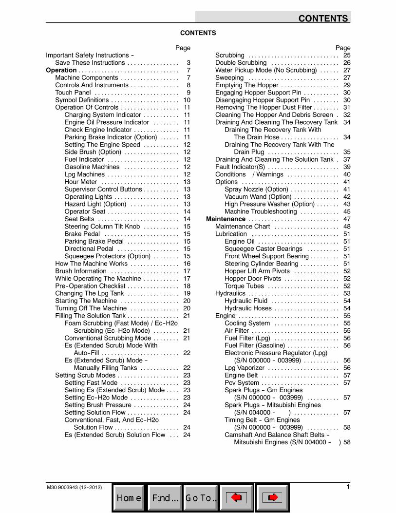
CONTENTS
PageImportant Safety Instructions --
Save These Instructions 3. . . . . . . . . . . . . . . .Operation 7. . . . . . . . . . . . . . . . . . . . . . . . . . . . . . .
Machine Components 7. . . . . . . . . . . . . . . . . .Controls And Instruments 8. . . . . . . . . . . . . . .Touch Panel 9. . . . . . . . . . . . . . . . . . . . . . . . . .Symbol Definitions 10. . . . . . . . . . . . . . . . . . . . .Operation Of Controls 11. . . . . . . . . . . . . . . . . .
Charging System Indicator 11. . . . . . . . . . .Engine Oil Pressure Indicator 11. . . . . . . .Check Engine Indicator 11. . . . . . . . . . . . . .Parking Brake Indicator (Option) 11. . . . . .Setting The Engine Speed 12. . . . . . . . . . .Side Brush (Option) 12. . . . . . . . . . . . . . . . .Fuel Indicator 12. . . . . . . . . . . . . . . . . . . . . .Gasoline Machines 12. . . . . . . . . . . . . . . . .Lpg Machines 12. . . . . . . . . . . . . . . . . . . . . .Hour Meter 13. . . . . . . . . . . . . . . . . . . . . . . .Supervisor Control Buttons 13. . . . . . . . . . .Operating Lights 13. . . . . . . . . . . . . . . . . . . .Hazard Light (Option) 13. . . . . . . . . . . . . . .Operator Seat 14. . . . . . . . . . . . . . . . . . . . . .Seat Belts 14. . . . . . . . . . . . . . . . . . . . . . . . .Steering Column Tilt Knob 15. . . . . . . . . . .Brake Pedal 15. . . . . . . . . . . . . . . . . . . . . . .Parking Brake Pedal 15. . . . . . . . . . . . . . . .Directional Pedal 15. . . . . . . . . . . . . . . . . . .Squeegee Protectors (Option) 15. . . . . . . .
How The Machine Works 16. . . . . . . . . . . . . . .Brush Information 17. . . . . . . . . . . . . . . . . . . . .While Operating The Machine 17. . . . . . . . . . .Pre--Operation Checklist 18. . . . . . . . . . . . . . . .Changing The Lpg Tank 19. . . . . . . . . . . . . . . .Starting The Machine 20. . . . . . . . . . . . . . . . . .Turning Off The Machine 20. . . . . . . . . . . . . . .Filling The Solution Tank 21. . . . . . . . . . . . . . . .
Foam Scrubbing (Fast Mode) / Ec--H2oScrubbing (Ec--H2o Mode) 21. . . . . . . .
Conventional Scrubbing Mode 21. . . . . . . .Es (Extended Scrub) Mode With
Auto--Fill 22. . . . . . . . . . . . . . . . . . . . . . . .Es (Extended Scrub) Mode --
Manually Filling Tanks 22. . . . . . . . . . . .Setting Scrub Modes 23. . . . . . . . . . . . . . . . . . .
Setting Fast Mode 23. . . . . . . . . . . . . . . . . .Setting Es (Extended Scrub) Mode 23. . . .Setting Ec--H2o Mode 23. . . . . . . . . . . . . . .Setting Brush Pressure 24. . . . . . . . . . . . . .Setting Solution Flow 24. . . . . . . . . . . . . . . .Conventional, Fast, And Ec--H2o
Solution Flow 24. . . . . . . . . . . . . . . . . . . .Es (Extended Scrub) Solution Flow 24. . .
PageScrubbing 25. . . . . . . . . . . . . . . . . . . . . . . . . . . .Double Scrubbing 26. . . . . . . . . . . . . . . . . . . . .Water Pickup Mode (No Scrubbing) 27. . . . . .Sweeping 27. . . . . . . . . . . . . . . . . . . . . . . . . . . .Emptying The Hopper 29. . . . . . . . . . . . . . . . . .Engaging Hopper Support Pin 30. . . . . . . . . . .Disengaging Hopper Support Pin 30. . . . . . . .Removing The Hopper Dust Filter 31. . . . . . . .Cleaning The Hopper And Debris Screen 32.Draining And Cleaning The Recovery Tank 34
Draining The Recovery Tank WithThe Drain Hose 34. . . . . . . . . . . . . . . . . .
Draining The Recovery Tank With TheDrain Plug 35. . . . . . . . . . . . . . . . . . . . . .
Draining And Cleaning The Solution Tank 37.Fault Indicator(S) 39. . . . . . . . . . . . . . . . . . . . . .Conditions / Warnings 40. . . . . . . . . . . . . . . .Options 41. . . . . . . . . . . . . . . . . . . . . . . . . . . . . .
Spray Nozzle (Option) 41. . . . . . . . . . . . . . .Vacuum Wand (Option) 42. . . . . . . . . . . . . .High Pressure Washer (Option) 43. . . . . . .Machine Troubleshooting 45. . . . . . . . . . . .
Maintenance 47. . . . . . . . . . . . . . . . . . . . . . . . . . . .Maintenance Chart 48. . . . . . . . . . . . . . . . . . . .Lubrication 51. . . . . . . . . . . . . . . . . . . . . . . . . . .
Engine Oil 51. . . . . . . . . . . . . . . . . . . . . . . . .Squeegee Caster Bearings 51. . . . . . . . . .Front Wheel Support Bearing 51. . . . . . . . .Steering Cylinder Bearing 51. . . . . . . . . . . .Hopper Lift Arm Pivots 52. . . . . . . . . . . . . .Hopper Door Pivots 52. . . . . . . . . . . . . . . . .Torque Tubes 52. . . . . . . . . . . . . . . . . . . . . .
Hydraulics 53. . . . . . . . . . . . . . . . . . . . . . . . . . . .Hydraulic Fluid 54. . . . . . . . . . . . . . . . . . . . .Hydraulic Hoses 54. . . . . . . . . . . . . . . . . . . .
Engine 55. . . . . . . . . . . . . . . . . . . . . . . . . . . . . . .Cooling System 55. . . . . . . . . . . . . . . . . . . .Air Filter 55. . . . . . . . . . . . . . . . . . . . . . . . . . .Fuel Filter (Lpg) 56. . . . . . . . . . . . . . . . . . . .Fuel Filter (Gasoline) 56. . . . . . . . . . . . . . . .Electronic Pressure Regulator (Lpg)
(S/N 000000 -- 003999) 56. . . . . . . . . . .Lpg Vaporizer 56. . . . . . . . . . . . . . . . . . . . . .Engine Belt 57. . . . . . . . . . . . . . . . . . . . . . . .Pcv System 57. . . . . . . . . . . . . . . . . . . . . . . .Spark Plugs -- Gm Engines
(S/N 000000 -- 003999) 57. . . . . . . . . .Spark Plugs -- Mitsubishi Engines
(S/N 004000 -- ) 57. . . . . . . . . . . . . .Timing Belt -- Gm Engines
(S/N 000000 -- 003999) 58. . . . . . . . . .Camshaft And Balance Shaft Belts --
Mitsubishi Engines (S/N 004000 -- ) 58
CONTENTS
M30 9003943 (12--2012)2
PageBattery 58. . . . . . . . . . . . . . . . . . . . . . . . . . . . . . .Fuses And Relays 58. . . . . . . . . . . . . . . . . . . . .
Relay Panel Fuses And Relays 58. . . . . . .Engine Harness Fuses And Relays 59. . .Optional Relays 59. . . . . . . . . . . . . . . . . . . .Circuit Breakers (Ec--H2o) 59. . . . . . . . . . .
Cleaning The Hopper Dust Filter 60. . . . . . . . .Thermo--Sentry 60. . . . . . . . . . . . . . . . . . . . .
Main Brushes 61. . . . . . . . . . . . . . . . . . . . . . . . .Replacing Or Rotating The
Main Brushes 61. . . . . . . . . . . . . . . . . . .Checking The Main Brush Pattern 63. . . .Adjusting The Main Brush Taper 64. . . . . .Adjusting The Main Brush Width 64. . . . . .
Side Brush (Option) 65. . . . . . . . . . . . . . . . . . . .Replacing The Side Brush 65. . . . . . . . . . .
Fast System 65. . . . . . . . . . . . . . . . . . . . . . . . . .Replacing The Fast--Pak Carton 65. . . . . .Cleaning The Fast Supply Hose
Connector 66. . . . . . . . . . . . . . . . . . . . . .Cleaning The Fast System Filter Screen 66Replacing The Fast System Filters 66. . . .
Ec--H2o Module Flush Procedure 67. . . . . . . .Cleaning The Ec--H2o Filter Screen 68. . . . . .Squeegee Blades 69. . . . . . . . . . . . . . . . . . . . . .
Replacing (Or Rotating) TheRear Squeegee Blades 69. . . . . . . . . . .
Replacing Or Rotating The SideSqueegee Blades 71. . . . . . . . . . . . . . . .
Replacing The Side Brush Squeegee Blade(S/N 000000--001278) (Option) 73. . . .
Replacing Or Adjusting The Side BrushSqueegee Blade (S/N 001279-- )(Option) 74. . . . . . . . . . . . . . . . . . . . . . . .
Leveling The Rear Squeegee 75. . . . . . . . .Adjusting The Rear Squeegee Blade
Deflection 76. . . . . . . . . . . . . . . . . . . . . . .Skirts And Seals 77. . . . . . . . . . . . . . . . . . . . . . .
Scrub Head Skirt 77. . . . . . . . . . . . . . . . . . .Recovery Tank Seal 77. . . . . . . . . . . . . . . . .Solution Tank Seals 77. . . . . . . . . . . . . . . . .
Brakes And Tires 78. . . . . . . . . . . . . . . . . . . . . .Brakes 78. . . . . . . . . . . . . . . . . . . . . . . . . . . .Tires 78. . . . . . . . . . . . . . . . . . . . . . . . . . . . . .Front Wheel 78. . . . . . . . . . . . . . . . . . . . . . .
Propelling Motor 78. . . . . . . . . . . . . . . . . . . . . . .Pushing, Towing, And Transporting
The Machine 79. . . . . . . . . . . . . . . . . . . . . . .Pushing Or Towing The Machine 79. . . . . .Transporting The Machine 79. . . . . . . . . . .
Machine Jacking 81. . . . . . . . . . . . . . . . . . . . . .Storage Information 81. . . . . . . . . . . . . . . . . . . .
Freeze Protection (Machines WithoutEc--H2o System) 82. . . . . . . . . . . . . . . .
Freeze Protection (Machines WithEc--H2o System) 82. . . . . . . . . . . . . . . .
Priming The Ec--H2o System 84. . . . . . . . .
PageSpecifications 85. . . . . . . . . . . . . . . . . . . . . . . . . .
General Machine Dimensions/Capacities 85.General Machine Performance 85. . . . . . . . . .Hydraulic System 86. . . . . . . . . . . . . . . . . . . . . .Tires 87. . . . . . . . . . . . . . . . . . . . . . . . . . . . . . . . .Steering 87. . . . . . . . . . . . . . . . . . . . . . . . . . . . . .Fast System 88. . . . . . . . . . . . . . . . . . . . . . . . . .Ec--H2o System 88. . . . . . . . . . . . . . . . . . . . . . .Machine Dimensions 89. . . . . . . . . . . . . . . . . . .
SAFETY PRECAUTIONS
3M30 9003943 (12--2012)
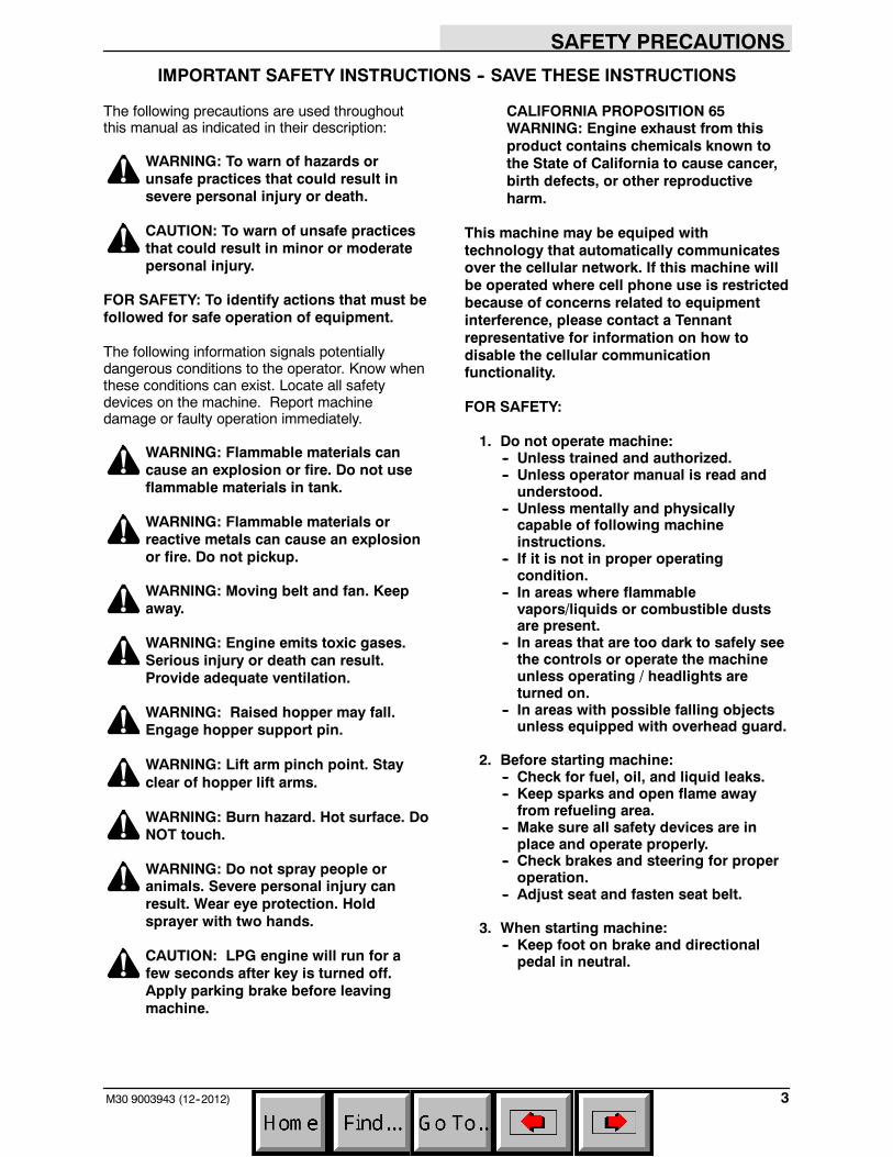
IMPORTANT SAFETY INSTRUCTIONS -- SAVE THESE INSTRUCTIONS
The following precautions are used throughoutthis manual as indicated in their description:
WARNING: To warn of hazards orunsafe practices that could result insevere personal injury or death.
CAUTION: To warn of unsafe practicesthat could result in minor or moderatepersonal injury.
FOR SAFETY: To identify actions that must befollowed for safe operation of equipment.
The following information signals potentiallydangerous conditions to the operator. Know whenthese conditions can exist. Locate all safetydevices on the machine. Report machinedamage or faulty operation immediately.
WARNING: Flammable materials cancause an explosion or fire. Do not useflammable materials in tank.
WARNING: Flammable materials orreactive metals can cause an explosionor fire. Do not pickup.
WARNING: Moving belt and fan. Keepaway.
WARNING: Engine emits toxic gases.Serious injury or death can result.Provide adequate ventilation.
WARNING: Raised hopper may fall.Engage hopper support pin.
WARNING: Lift arm pinch point. Stayclear of hopper lift arms.
WARNING: Burn hazard. Hot surface. DoNOT touch.
WARNING: Do not spray people oranimals. Severe personal injury canresult. Wear eye protection. Holdsprayer with two hands.
CAUTION: LPG engine will run for afew seconds after key is turned off.Apply parking brake before leavingmachine.
CALIFORNIA PROPOSITION 65WARNING: Engine exhaust from thisproduct contains chemicals known tothe State of California to cause cancer,birth defects, or other reproductiveharm.
This machine may be equiped withtechnology that automatically communicatesover the cellular network. If this machine willbe operated where cell phone use is restrictedbecause of concerns related to equipmentinterference, please contact a Tennantrepresentative for information on how todisable the cellular communicationfunctionality.
FOR SAFETY:
1. Do not operate machine:-- Unless trained and authorized.-- Unless operator manual is read andunderstood.
-- Unless mentally and physicallycapable of following machineinstructions.
-- If it is not in proper operatingcondition.
-- In areas where flammablevapors/liquids or combustible dustsare present.
-- In areas that are too dark to safely seethe controls or operate the machineunless operating / headlights areturned on.
-- In areas with possible falling objectsunless equipped with overhead guard.
2. Before starting machine:-- Check for fuel, oil, and liquid leaks.-- Keep sparks and open flame awayfrom refueling area.
-- Make sure all safety devices are inplace and operate properly.
-- Check brakes and steering for properoperation.
-- Adjust seat and fasten seat belt.
3. When starting machine:-- Keep foot on brake and directionalpedal in neutral.
SAFETY PRECAUTIONS
M30 9003943 (12--2012)4
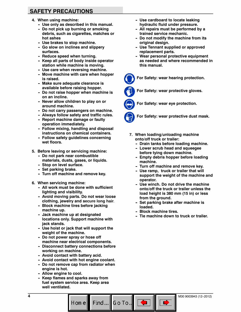
4. When using machine:-- Use only as described in this manual.-- Do not pick up burning or smokingdebris, such as cigarettes, matches orhot ashes
-- Use brakes to stop machine.-- Go slow on inclines and slipperysurfaces.
-- Reduce speed when turning.-- Keep all parts of body inside operatorstation while machine is moving.
-- Use care when reversing machine.-- Move machine with care when hopperis raised.
-- Make sure adequate clearance isavailable before raising hopper.
-- Do not raise hopper when machine ison an incline.
-- Never allow children to play on oraround machine.
-- Do not carry passengers on machine.-- Always follow safety and traffic rules.-- Report machine damage or faultyoperation immediately.
-- Follow mixing, handling and disposalinstructions on chemical containers.
-- Follow safety guidelines concerningwet floors.
5. Before leaving or servicing machine:-- Do not park near combustiblematerials, dusts, gases, or liquids.
-- Stop on level surface.-- Set parking brake.-- Turn off machine and remove key.
6. When servicing machine:-- All work must be done with sufficientlighting and visibility.
-- Avoid moving parts. Do not wear looseclothing, jewelry and secure long hair.
-- Block machine tires before jackingmachine up.
-- Jack machine up at designatedlocations only. Support machine withjack stands.
-- Use hoist or jack that will support theweight of the machine.
-- Do not power spray or hose offmachine near electrical components.
-- Disconnect battery connections beforeworking on machine.
-- Avoid contact with battery acid.-- Avoid contact with hot engine coolant.-- Do not remove cap from radiator whenengine is hot.
-- Allow engine to cool.-- Keep flames and sparks away fromfuel system service area. Keep areawell ventilated.
-- Use cardboard to locate leakinghydraulic fluid under pressure.
-- All repairs must be performed by atrained service mechanic.
-- Do not modify the machine from itsoriginal design.
-- Use Tennant supplied or approvedreplacement parts.
-- Wear personal protective equipmentas needed and where recommended inthis manual.
For Safety: wear hearing protection.
For Safety: wear protective gloves.
For Safety: wear eye protection.
For Safety: wear protective dust mask.
7. When loading/unloading machineonto/off truck or trailer:-- Drain tanks before loading machine.-- Lower scrub head and squeegeebefore tying down machine.
-- Empty debris hopper before loadingmachine.
-- Turn off machine and remove key.-- Use ramp, truck or trailer that willsupport the weight of the machine andoperator.
-- Use winch. Do not drive the machineonto/off the truck or trailer unless theload height is 380 mm (15 in) or lessfrom the ground.
-- Set parking brake after machine isloaded.
-- Block machine tires.-- Tie machine down to truck or trailer.
SAFETY PRECAUTIONS
5M30 9003943 (1--08)
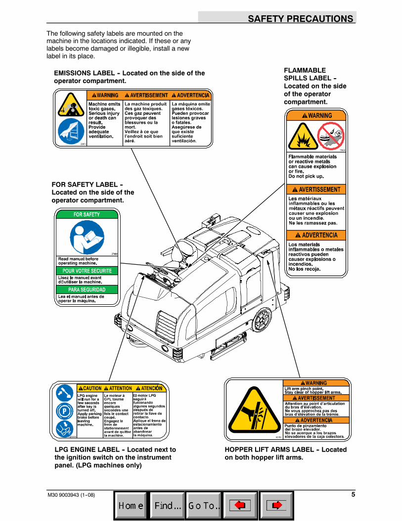
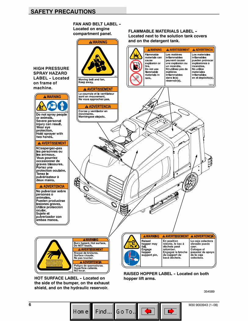
The following safety labels are mounted on themachine in the locations indicated. If these or anylabels become damaged or illegible, install a newlabel in its place.
EMISSIONS LABEL -- Located on the side of theoperator compartment.
FOR SAFETY LABEL --Located on the side of theoperator compartment.
FLAMMABLESPILLS LABEL --Located on the sideof the operatorcompartment.
LPG ENGINE LABEL -- Located next tothe ignition switch on the instrumentpanel. (LPG machines only)
HOPPER LIFT ARMS LABEL -- Locatedon both hopper lift arms.
SAFETY PRECAUTIONS
M30 9003943 (1--08)6
FAN AND BELT LABEL --Located on enginecompartment panel.
FLAMMABLE MATERIALS LABEL --Located next to the solution tank coversand on the detergent tank.
HOT SURFACE LABEL -- Located onthe side of the bumper, on the exhaustshield, and on the hydraulic reservoir.
RAISED HOPPER LABEL -- Located on bothhopper lift arms.
HIGH PRESSURESPRAY HAZARDLABEL -- Locatedon frame ofmachine.
354589
OPERATION
7M30 9003943 (4--10)
OPERATION
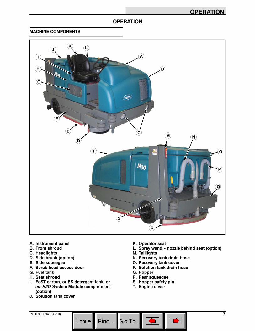
MACHINE COMPONENTS
C
F
I
J
M
Q
B
A
E
H
L
N
O
P
D
G
K
R
T
S
A. Instrument panelB. Front shroudC. HeadlightsD. Side brush (option)E. Side squeegeeF. Scrub head access doorG. Fuel tankH. Seat shroudI. FaST carton, or ES detergent tank, or
ec-H2O System Module compartment(option)
J. Solution tank cover
K. Operator seatL. Spray wand -- nozzle behind seat (option)M. TaillightsN. Recovery tank drain hoseO. Recovery tank coverP. Solution tank drain hoseQ. HopperR. Rear squeegeeS. Hopper safety pinT. Engine cover
OPERATION
8 M30 9003943 (4--10)
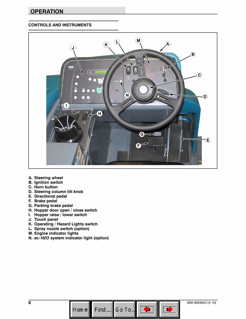
CONTROLS AND INSTRUMENTS
B
I
H
FE
L M
G
K A
C
D
J
N
A. Steering wheelB. Ignition switchC. Horn buttonD. Steering column tilt knobE. Directional pedalF. Brake pedalG. Parking brake pedalH. Hopper door open / close switchI. Hopper raise / lower switchJ. Touch panelK. Operating / Hazard Lights switchL. Spray nozzle switch (option)M. Engine indicator lightsN. ec-H2O system indicator light (option)
OPERATION
9M30 9003943 (4--10)
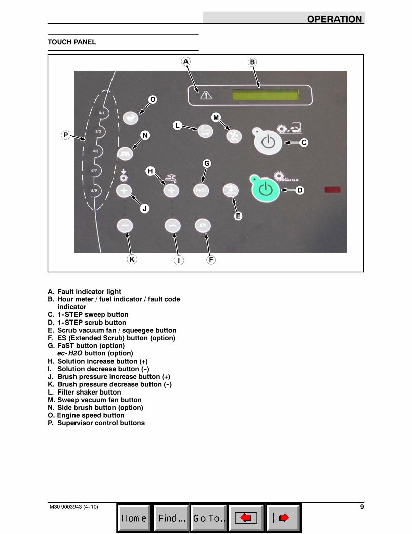
TOUCH PANEL
H
C
G
A
N
JE
B
D
F
LM
O
P
IK
A. Fault indicator lightB. Hour meter / fuel indicator / fault code
indicatorC. 1--STEP sweep buttonD. 1--STEP scrub buttonE. Scrub vacuum fan / squeegee buttonF. ES (Extended Scrub) button (option)G. FaST button (option)
ec-H2O button (option)H. Solution increase button (+)I. Solution decrease button (--)J. Brush pressure increase button (+)K. Brush pressure decrease button (--)L. Filter shaker buttonM. Sweep vacuum fan buttonN. Side brush button (option)O. Engine speed buttonP. Supervisor control buttons
OPERATION
10 M30 9003943 (4--10)
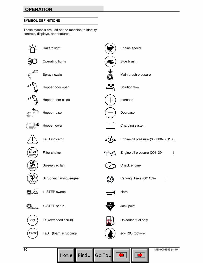
SYMBOL DEFINITIONS
These symbols are usd on the machine to identifycontrols, displays, and features.
Hazard light Engine speed
Operating lights Side brush
Spray nozzle Main brush pressure
Hopper door open Solution flow
Hopper door close Increase
Hopper raise Decrease
Hopper lower Charging system
Fault indicator Engine oil pressure (000000--001138)
Filter shaker Engine oil pressure (001139-- )
Sweep vac fan Check engine
Scrub vac fan/squeegee Parking Brake (001139-- )
1--STEP sweep Horn
1--STEP scrub Jack point
ES (extended scrub) Unleaded fuel only
FaST (foam scrubbing) ec--H2O (option)
OPERATION
11M30 9003943 (6--09)
OPERATION OF CONTROLS
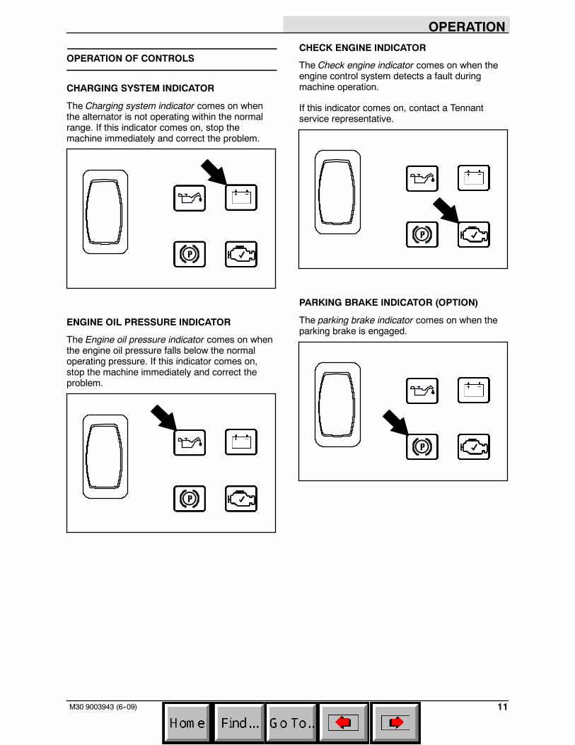
CHARGING SYSTEM INDICATOR
The Charging system indicator comes on whenthe alternator is not operating within the normalrange. If this indicator comes on, stop themachine immediately and correct the problem.
ENGINE OIL PRESSURE INDICATOR
The Engine oil pressure indicator comes on whenthe engine oil pressure falls below the normaloperating pressure. If this indicator comes on,stop the machine immediately and correct theproblem.
CHECK ENGINE INDICATOR
The Check engine indicator comes on when theengine control system detects a fault duringmachine operation.
If this indicator comes on, contact a Tennantservice representative.
PARKING BRAKE INDICATOR (OPTION)
The parking brake indicator comes on when theparking brake is engaged.
OPERATION
12 M30 9003943 (1--08)
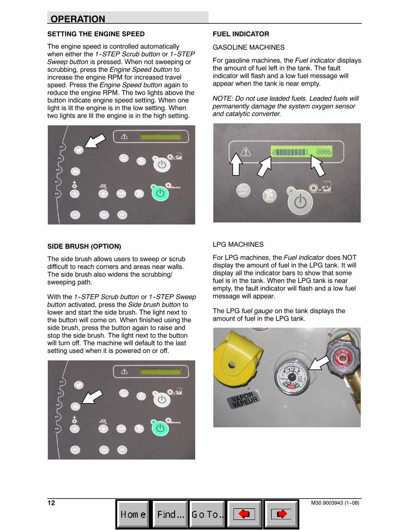
SETTING THE ENGINE SPEED
The engine speed is controlled automaticallywhen either the 1--STEP Scrub button or 1--STEPSweep button is pressed. When not sweeping orscrubbing, press the Engine Speed button toincrease the engine RPM for increased travelspeed. Press the Engine Speed button again toreduce the engine RPM. The two lights above thebutton indicate engine speed setting. When onelight is lit the engine is in the low setting. Whentwo lights are lit the engine is in the high setting.
SIDE BRUSH (OPTION)
The side brush allows users to sweep or scrubdifficult to reach corners and areas near walls.The side brush also widens the scrubbing/sweeping path.
With the 1--STEP Scrub button or 1--STEP Sweepbutton activated, press the Side brush button tolower and start the side brush. The light next tothe button will come on. When finished using theside brush, press the button again to raise andstop the side brush. The light next to the buttonwill turn off. The machine will default to the lastsetting used when it is powered on or off.
FUEL INDICATOR
GASOLINE MACHINES
For gasoline machines, the Fuel indicator displaysthe amount of fuel left in the tank. The faultindicator will flash and a low fuel message willappear when the tank is near empty.
NOTE: Do not use leaded fuels. Leaded fuels willpermanently damage the system oxygen sensorand catalytic converter.
LPG MACHINES
For LPG machines, the Fuel indicator does NOTdisplay the amount of fuel in the LPG tank. It willdisplay all the indicator bars to show that somefuel is in the tank. When the LPG tank is nearempty, the fault indicator will flash and a low fuelmessage will appear.
The LPG fuel gauge on the tank displays theamount of fuel in the LPG tank.
OPERATION
13M30 9003943 (1--08)
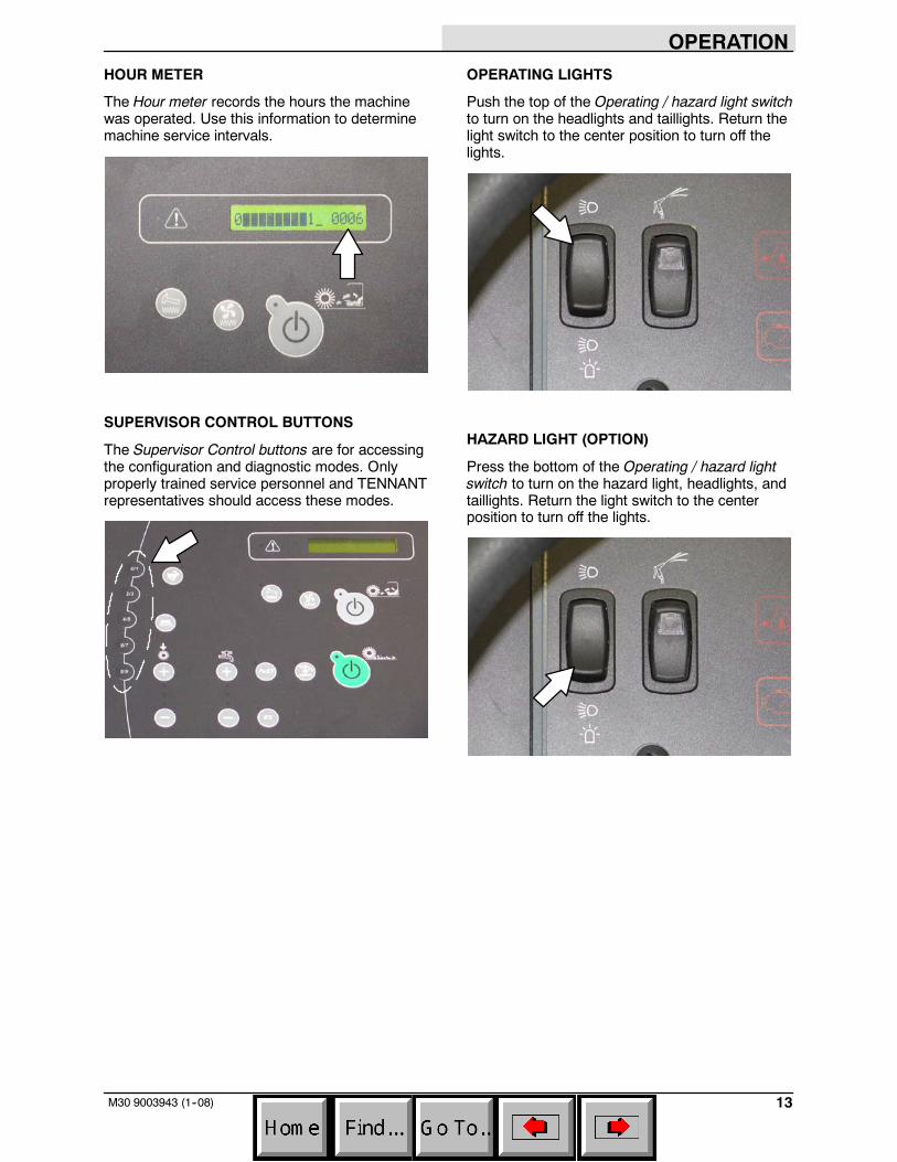
HOUR METER
The Hour meter records the hours the machinewas operated. Use this information to determinemachine service intervals.
SUPERVISOR CONTROL BUTTONS
The Supervisor Control buttons are for accessingthe configuration and diagnostic modes. Onlyproperly trained service personnel and TENNANTrepresentatives should access these modes.
OPERATING LIGHTS
Push the top of the Operating / hazard light switchto turn on the headlights and taillights. Return thelight switch to the center position to turn off thelights.
HAZARD LIGHT (OPTION)
Press the bottom of the Operating / hazard lightswitch to turn on the hazard light, headlights, andtaillights. Return the light switch to the centerposition to turn off the lights.
OPERATION
14 M30 9003943 (1--08)
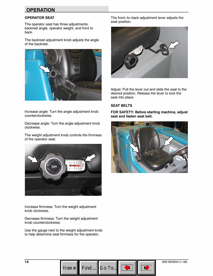
OPERATOR SEAT
The operator seat has three adjustments:backrest angle, operator weight, and front toback.
The backrest adjustment knob adjusts the angleof the backrest.
Increase angle: Turn the angle adjustment knobcounterclockwise.
Decrease angle: Turn the angle adjustment knobclockwise.
The weight adjustment knob controls the firmnessof the operator seat.
Increase firmness: Turn the weight adjustmentknob clockwise.
Decrease firmness: Turn the weight adjustmentknob counterclockwise.
Use the gauge next to the weight adjustment knobto help determine seat firmness for the operator.
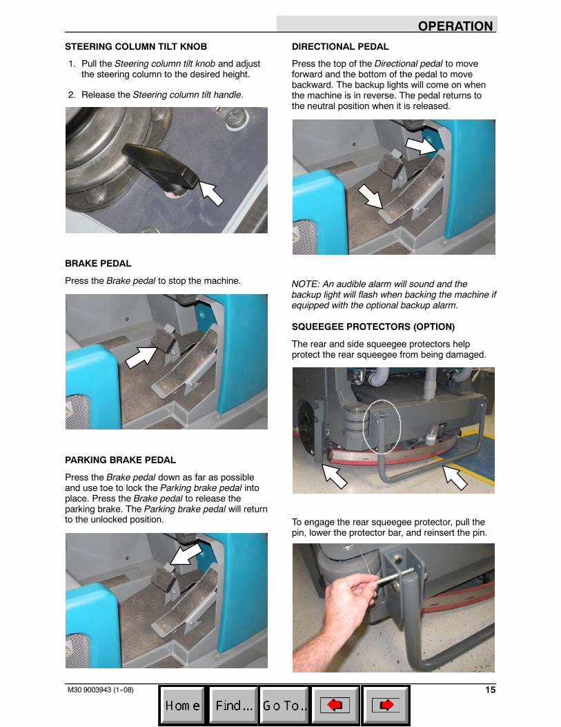
The front--to--back adjustment lever adjusts theseat position.
Adjust: Pull the lever out and slide the seat to thedesired position. Release the lever to lock theseat into place.
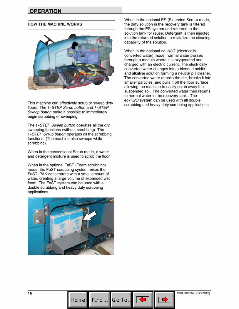
SEAT BELTS
FOR SAFETY: Before starting machine, adjustseat and fasten seat belt.
OPERATION
15M30 9003943 (1--08)
STEERING COLUMN TILT KNOB
1. Pull the Steering column tilt knob and adjustthe steering column to the desired height.
2. Release the Steering column tilt handle.
BRAKE PEDAL
Press the Brake pedal to stop the machine.
PARKING BRAKE PEDAL
Press the Brake pedal down as far as possibleand use toe to lock the Parking brake pedal intoplace. Press the Brake pedal to release theparking brake. The Parking brake pedal will returnto the unlocked position.
DIRECTIONAL PEDAL
Press the top of the Directional pedal to moveforward and the bottom of the pedal to movebackward. The backup lights will come on whenthe machine is in reverse. The pedal returns tothe neutral position when it is released.
NOTE: An audible alarm will sound and thebackup light will flash when backing the machine ifequipped with the optional backup alarm.
SQUEEGEE PROTECTORS (OPTION)
The rear and side squeegee protectors helpprotect the rear squeegee from being damaged.
To engage the rear squeegee protector, pull thepin, lower the protector bar, and reinsert the pin.
OPERATION
16 M30 9003943 (12--2012)
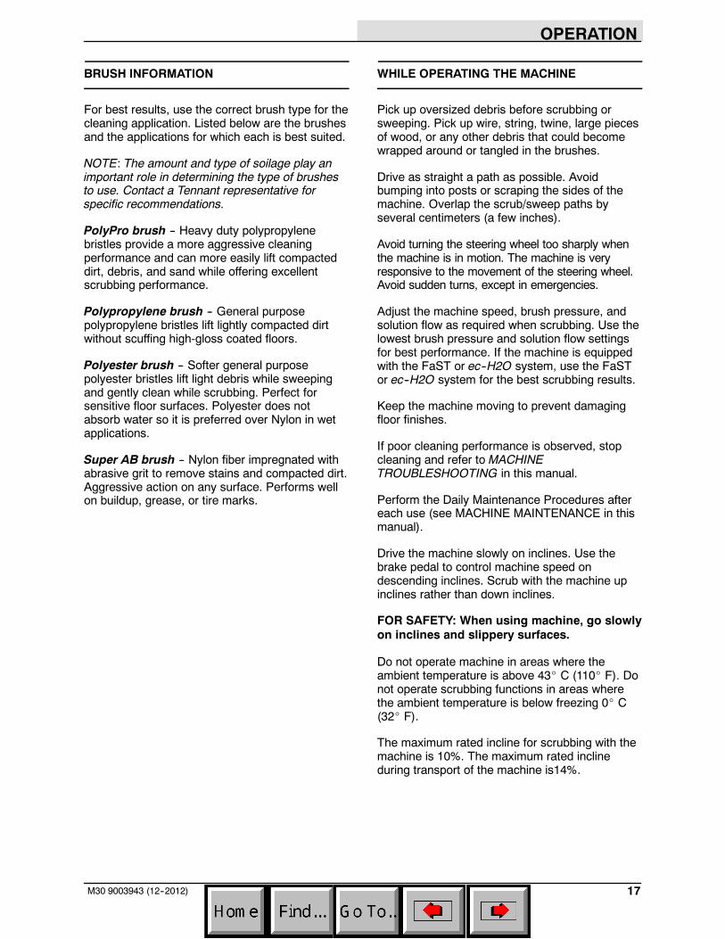
HOW THE MACHINE WORKS
This machine can effectively scrub or sweep dirtyfloors. The 1--STEP Scrub button and 1--STEPSweep button make it possible to immediatelybegin scrubbing or sweeping.
The 1--STEP Sweep button operates all the drysweeping functions (without scrubbing). The1--STEP Scrub button operates all the scrubbingfunctions. (The machine also sweeps whilescrubbing).
When in the conventional Scrub mode, a waterand detergent mixture is used to scrub the floor.
When in the optional FaST (Foam scrubbing)mode, the FaST scrubbing system mixes theFaST--PAK concentrate with a small amount ofwater, creating a large volume of expanded wetfoam. The FaST system can be used with alldouble scrubbing and heavy duty scrubbingapplications.
When in the optional ES (Extended Scrub) mode,the dirty solution in the recovery tank is filteredthrough the ES system and returned to thesolution tank for reuse. Detergent is then injectedinto the returned solution to revitalize the cleaningcapability of the solution.
When in the optional ec--H2O (electricallyconverted water) mode, normal water passesthrough a module where it is oxygenated andcharged with an electric current. The electricallyconverted water changes into a blended acidicand alkaline solution forming a neutral pH cleaner.The converted water attacks the dirt, breaks it intosmaller particles, and pulls it off the floor surfaceallowing the machine to easily scrub away thesuspended soil. The converted water then returnsto normal water in the recovery tank . Theec--H2O system can be used with all doublescrubbing and heavy duty scrubbing applications.
OPERATION
17M30 9003943 (12--2012)
BRUSH INFORMATION
For best results, use the correct brush type for thecleaning application. Listed below are the brushesand the applications for which each is best suited.
NOTE: The amount and type of soilage play animportant role in determining the type of brushesto use. Contact a Tennant representative forspecific recommendations.
PolyPro brush -- Heavy duty polypropylenebristles provide a more aggressive cleaningperformance and can more easily lift compacteddirt, debris, and sand while offering excellentscrubbing performance.
Polypropylene brush -- General purposepolypropylene bristles lift lightly compacted dirtwithout scuffing high-gloss coated floors.
Polyester brush -- Softer general purposepolyester bristles lift light debris while sweepingand gently clean while scrubbing. Perfect forsensitive floor surfaces. Polyester does notabsorb water so it is preferred over Nylon in wetapplications.
Super AB brush -- Nylon fiber impregnated withabrasive grit to remove stains and compacted dirt.Aggressive action on any surface. Performs wellon buildup, grease, or tire marks.
WHILE OPERATING THE MACHINE
Pick up oversized debris before scrubbing orsweeping. Pick up wire, string, twine, large piecesof wood, or any other debris that could becomewrapped around or tangled in the brushes.
Drive as straight a path as possible. Avoidbumping into posts or scraping the sides of themachine. Overlap the scrub/sweep paths byseveral centimeters (a few inches).
Avoid turning the steering wheel too sharply whenthe machine is in motion. The machine is veryresponsive to the movement of the steering wheel.Avoid sudden turns, except in emergencies.
Adjust the machine speed, brush pressure, andsolution flow as required when scrubbing. Use thelowest brush pressure and solution flow settingsfor best performance. If the machine is equippedwith the FaST or ec--H2O system, use the FaSTor ec--H2O system for the best scrubbing results.
Keep the machine moving to prevent damagingfloor finishes.
If poor cleaning performance is observed, stopcleaning and refer to MACHINETROUBLESHOOTING in this manual.
Perform the Daily Maintenance Procedures aftereach use (see MACHINE MAINTENANCE in thismanual).
Drive the machine slowly on inclines. Use thebrake pedal to control machine speed ondescending inclines. Scrub with the machine upinclines rather than down inclines.
FOR SAFETY: When using machine, go slowlyon inclines and slippery surfaces.
Do not operate machine in areas where theambient temperature is above 43_ C (110_ F). Donot operate scrubbing functions in areas wherethe ambient temperature is below freezing 0_ C(32_ F).
The maximum rated incline for scrubbing with themachine is 10%. The maximum rated inclineduring transport of the machine is14%.
OPERATION
18 M30 9003943 (12--2012)
PRE--OPERATION CHECKLIST
- Check the hydraulic fluid level.
- Check the fuel level.
- Check the machine for fluid leaks.
- Check the condition of the main brushes.Remove string, banding, plastic wrap, or otherdebris wrapped around the brushes.
- Check the main brush compartment rightskirts, seals, and squeegee for damage andwear.
- Side Brush Option: Check the condition of thebrush. Remove string, banding, plastic wrap,or other debris wrapped around the brush.
- Side Brush Option: Check the condition of theside brush skirt or squeegee.
- Check the radiator and hydraulic cooler finsfor debris.
- Check the engine coolant level.
- Check the engine oil level.
- Check the main brush compartment left skirts,seals, and squeegee for damage and wear.
- Check the left solution tank cover seal fordamage and wear.
- Check the recovery tank cover seal fordamage and wear.
- Clean the vacuum fan debris filter.
- Drain and clean the recovery tank.
- ES Option: Drain and clean the solution tank,float sensor, and ES filter.
- Check the right solution tank cover seal fordamage and wear.
- Check the condition of the hopper dust filterand seals.
- Clean the hopper and the debris screen.
- Check the squeegee hose for debris orblockage.
- Check the squeegees for damage, wear, anddeflection adjustment.
- FaST Scrubbing: Check the FaST--PAKconcentrate agent level. Replace carton asneeded. See the INSTALLING THEFaST--PAK CARTON section of the manual.
- FaST Scrubbing: Ensure all conventionalcleaning agents are drained and rinsed fromthe solution tank.
- FaST Scrubbing: Ensure the solution tank isfilled with clear cool water only.
- Check the horn, headlights, taillights, safetylights, and backup alarm (if equipped).
- Check the brakes and steering for properoperation.
- Check the service records to determinemaintenance requirements.
OPERATION
19M30 9003943 (12--2012)
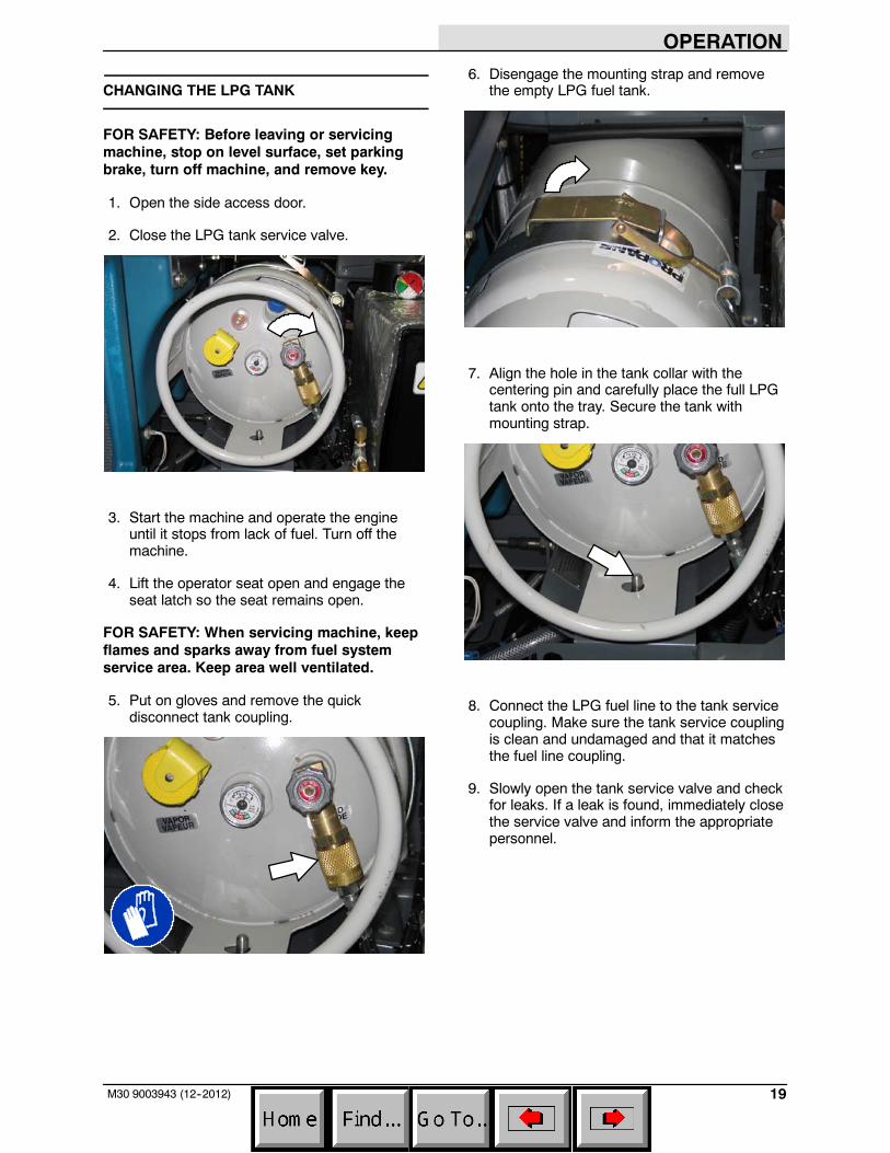
CHANGING THE LPG TANK
FOR SAFETY: Before leaving or servicingmachine, stop on level surface, set parkingbrake, turn off machine, and remove key.
1. Open the side access door.
2. Close the LPG tank service valve.
3. Start the machine and operate the engineuntil it stops from lack of fuel. Turn off themachine.
4. Lift the operator seat open and engage theseat latch so the seat remains open.
FOR SAFETY: When servicing machine, keepflames and sparks away from fuel systemservice area. Keep area well ventilated.
5. Put on gloves and remove the quickdisconnect tank coupling.
6. Disengage the mounting strap and removethe empty LPG fuel tank.
7. Align the hole in the tank collar with thecentering pin and carefully place the full LPGtank onto the tray. Secure the tank withmounting strap.
8. Connect the LPG fuel line to the tank servicecoupling. Make sure the tank service couplingis clean and undamaged and that it matchesthe fuel line coupling.
9. Slowly open the tank service valve and checkfor leaks. If a leak is found, immediately closethe service valve and inform the appropriatepersonnel.
OPERATION
20 M30 9003943 (12--2012)
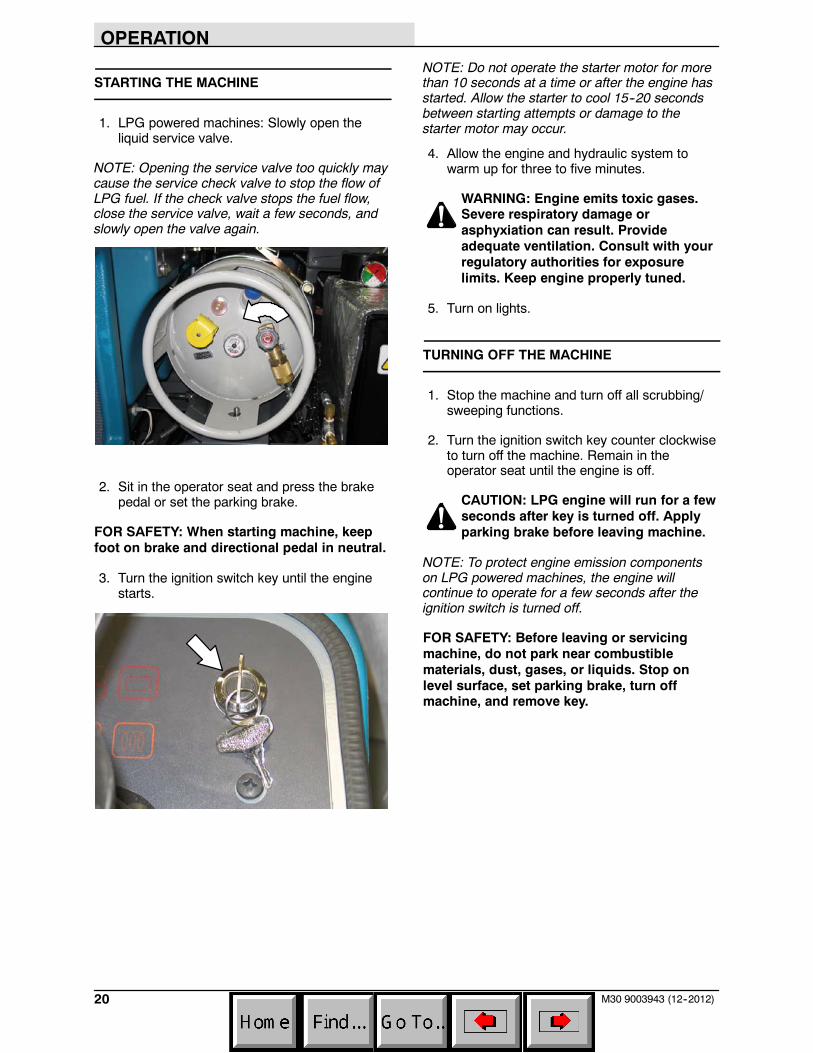
STARTING THE MACHINE
1. LPG powered machines: Slowly open theliquid service valve.
NOTE: Opening the service valve too quickly maycause the service check valve to stop the flow ofLPG fuel. If the check valve stops the fuel flow,close the service valve, wait a few seconds, andslowly open the valve again.
2. Sit in the operator seat and press the brakepedal or set the parking brake.
FOR SAFETY: When starting machine, keepfoot on brake and directional pedal in neutral.
3. Turn the ignition switch key until the enginestarts.
NOTE: Do not operate the starter motor for morethan 10 seconds at a time or after the engine hasstarted. Allow the starter to cool 15--20 secondsbetween starting attempts or damage to thestarter motor may occur.
4. Allow the engine and hydraulic system towarm up for three to five minutes.
WARNING: Engine emits toxic gases.Severe respiratory damage orasphyxiation can result. Provideadequate ventilation. Consult with yourregulatory authorities for exposurelimits. Keep engine properly tuned.
5. Turn on lights.
TURNING OFF THE MACHINE
1. Stop the machine and turn off all scrubbing/sweeping functions.
2. Turn the ignition switch key counter clockwiseto turn off the machine. Remain in theoperator seat until the engine is off.
CAUTION: LPG engine will run for a fewseconds after key is turned off. Applyparking brake before leaving machine.
NOTE: To protect engine emission componentson LPG powered machines, the engine willcontinue to operate for a few seconds after theignition switch is turned off.
FOR SAFETY: Before leaving or servicingmachine, do not park near combustiblematerials, dust, gases, or liquids. Stop onlevel surface, set parking brake, turn offmachine, and remove key.
OPERATION
21M30 9003943 (12--2012)
FILLING THE SOLUTION TANK
FOAM SCRUBBING (FaST MODE) / ec--H2OSCRUBBING (ec--H2O MODE)
FOR SAFETY: Before leaving or servicingmachine, stop on level surface, set parkingbrake, turn off machine, and remove key.
1. Open either the left or right solution tank fillcover.
2. Fill the solution tank with only clean COOLWATER (less than 21C / 70F). DO NOT usehot water or add any conventional floorcleaning detergents or FaST system failuremay result.
WARNING: Flammable materials cancause an explosion or fire. Do not useflammable materials in tank(s).
NOTE: To install or change the FaST--PAKcarton, see the REPLACING THE FaST--PAKCARTON section of the manual.
NOTE: Do not use the FaST or ec--H2O systemwhen there are conventional cleaning detergentsin the solution tank. Drain, rinse, and refill thesolution tank with clear cool water beforeoperating the FaST or ec--H2O system.Conventional cleaning detergents may cause aFaST or ec--H2O system failure.
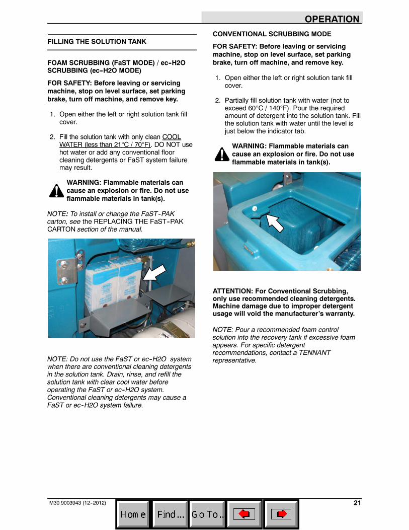
CONVENTIONAL SCRUBBING MODE
FOR SAFETY: Before leaving or servicingmachine, stop on level surface, set parkingbrake, turn off machine, and remove key.
1. Open either the left or right solution tank fillcover.
2. Partially fill solution tank with water (not toexceed 60C / 140F). Pour the requiredamount of detergent into the solution tank. Fillthe solution tank with water until the level isjust below the indicator tab.
WARNING: Flammable materials cancause an explosion or fire. Do not useflammable materials in tank(s).
ATTENTION: For Conventional Scrubbing,only use recommended cleaning detergents.Machine damage due to improper detergentusage will void the manufacturer’s warranty.
NOTE: Pour a recommended foam controlsolution into the recovery tank if excessive foamappears. For specific detergentrecommendations, contact a TENNANTrepresentative.
OPERATION
22 M30 9003943 (1--08)
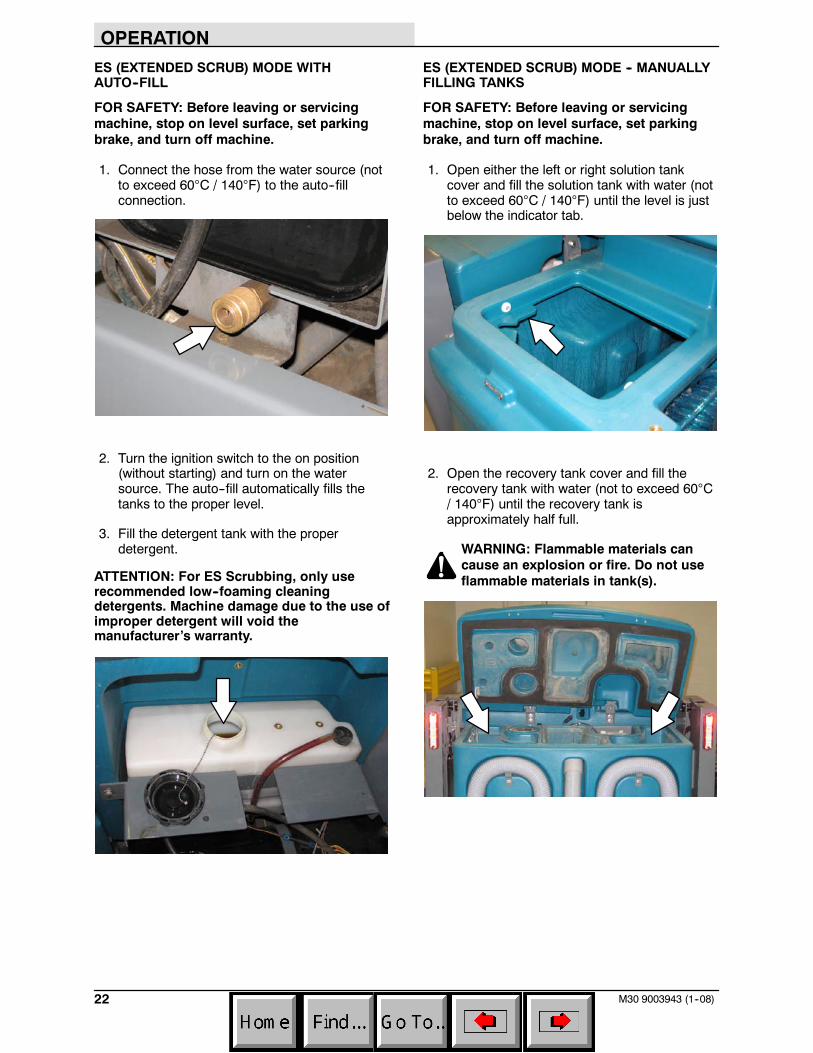
ES (EXTENDED SCRUB) MODE WITHAUTO--FILL
FOR SAFETY: Before leaving or servicingmachine, stop on level surface, set parkingbrake, and turn off machine.
1. Connect the hose from the water source (notto exceed 60C / 140F) to the auto--fillconnection.
2. Turn the ignition switch to the on position(without starting) and turn on the watersource. The auto--fill automatically fills thetanks to the proper level.
3. Fill the detergent tank with the properdetergent.
ATTENTION: For ES Scrubbing, only userecommended low--foaming cleaningdetergents. Machine damage due to the use ofimproper detergent will void themanufacturer’s warranty.
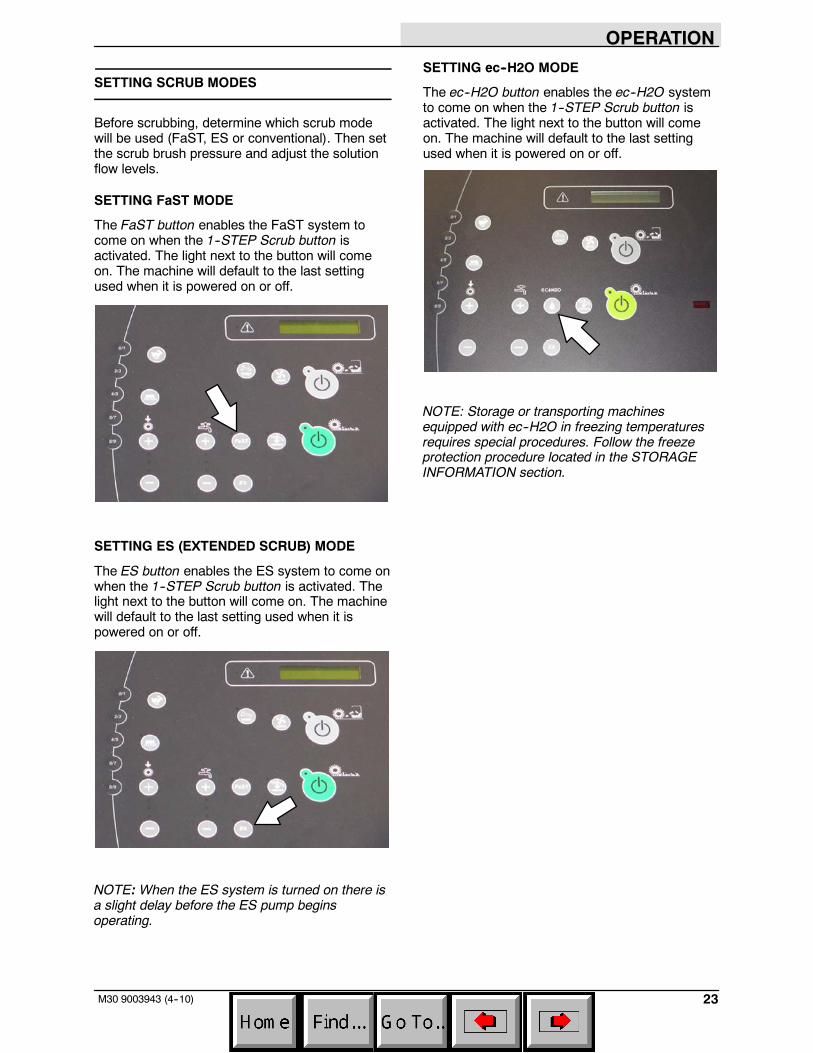
ES (EXTENDED SCRUB) MODE -- MANUALLYFILLING TANKS
FOR SAFETY: Before leaving or servicingmachine, stop on level surface, set parkingbrake, and turn off machine.
1. Open either the left or right solution tankcover and fill the solution tank with water (notto exceed 60C / 140F) until the level is justbelow the indicator tab.
2. Open the recovery tank cover and fill therecovery tank with water (not to exceed 60C/ 140F) until the recovery tank isapproximately half full.
WARNING: Flammable materials cancause an explosion or fire. Do not useflammable materials in tank(s).
OPERATION
23M30 9003943 (4--10)
SETTING SCRUB MODES
Before scrubbing, determine which scrub modewill be used (FaST, ES or conventional). Then setthe scrub brush pressure and adjust the solutionflow levels.
SETTING FaST MODE
The FaST button enables the FaST system tocome on when the 1--STEP Scrub button isactivated. The light next to the button will comeon. The machine will default to the last settingused when it is powered on or off.
SETTING ES (EXTENDED SCRUB) MODE
The ES button enables the ES system to come onwhen the 1--STEP Scrub button is activated. Thelight next to the button will come on. The machinewill default to the last setting used when it ispowered on or off.
NOTE: When the ES system is turned on there isa slight delay before the ES pump beginsoperating.
SETTING ec--H2O MODE
The ec--H2O button enables the ec--H2O systemto come on when the 1--STEP Scrub button isactivated. The light next to the button will comeon. The machine will default to the last settingused when it is powered on or off.
NOTE: Storage or transporting machinesequipped with ec--H2O in freezing temperaturesrequires special procedures. Follow the freezeprotection procedure located in the STORAGEINFORMATION section.
OPERATION
24 M30 9003943 (4--10)
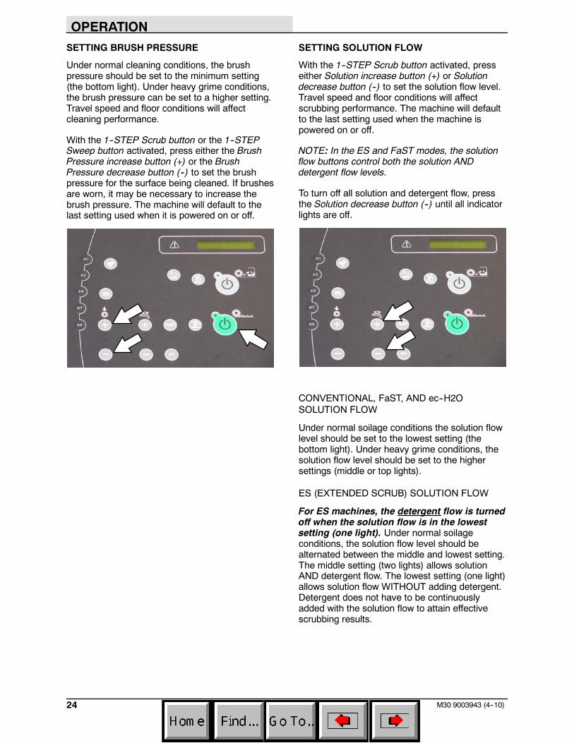
SETTING BRUSH PRESSURE
Under normal cleaning conditions, the brushpressure should be set to the minimum setting(the bottom light). Under heavy grime conditions,the brush pressure can be set to a higher setting.Travel speed and floor conditions will affectcleaning performance.
With the 1--STEP Scrub button or the 1--STEPSweep button activated, press either the BrushPressure increase button (+) or the BrushPressure decrease button (--) to set the brushpressure for the surface being cleaned. If brushesare worn, it may be necessary to increase thebrush pressure. The machine will default to thelast setting used when it is powered on or off.
SETTING SOLUTION FLOW
With the 1--STEP Scrub button activated, presseither Solution increase button (+) or Solutiondecrease button (--) to set the solution flow level.Travel speed and floor conditions will affectscrubbing performance. The machine will defaultto the last setting used when the machine ispowered on or off.
NOTE: In the ES and FaST modes, the solutionflow buttons control both the solution ANDdetergent flow levels.
To turn off all solution and detergent flow, pressthe Solution decrease button (--) until all indicatorlights are off.
CONVENTIONAL, FaST, AND ec--H2OSOLUTION FLOW
Under normal soilage conditions the solution flowlevel should be set to the lowest setting (thebottom light). Under heavy grime conditions, thesolution flow level should be set to the highersettings (middle or top lights).
ES (EXTENDED SCRUB) SOLUTION FLOW
For ES machines, the detergent flow is turnedoff when the solution flow is in the lowestsetting (one light). Under normal soilageconditions, the solution flow level should bealternated between the middle and lowest setting.The middle setting (two lights) allows solutionAND detergent flow. The lowest setting (one light)allows solution flow WITHOUT adding detergent.Detergent does not have to be continuouslyadded with the solution flow to attain effectivescrubbing results.
OPERATION
25M30 9003943 (4--10)
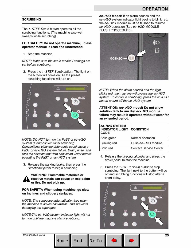
SCRUBBING
The 1--STEP Scrub button operates all thescrubbing functions. (The machine also wetsweeps while scrubbing).
FOR SAFETY: Do not operate machine, unlessoperator manual is read and understood.
1. Start the machine.
NOTE: Make sure the scrub modes / settings areset before scrubbing.
2. Press the 1--STEP Scrub button. The light onthe button will come on. All the presetscrubbing functions will turn on.
NOTE: DO NOT turn on the FaST or ec--H2Osystem during conventional scrubbing.Conventional cleaning detergents could cause aFaST or ec--H2O system failure. Drain, rinse, andrefill the solution tank with cool clean water beforeoperating the FaST or ec--H2O system.
3. Release the parking brake, then press theDirectional pedal to begin scrubbing.
WARNING: Flammable materials orreactive metals can cause an explosionor fire. Do not pick up.
FOR SAFETY: When using machine, go slowon inclines and slippery surfaces.
NOTE: The squeegee automatically rises whenthe machine is driven backwards. This preventsdamaging the squeegee.
NOTE:The ec--H2O system indicator light will notturn on until the machine starts scrubbing.
ec-H2O Model: If an alarm sounds and theec--H2O system indicator light begins to blink red,the ec--H2O module must be flushed to resumeec--H2O operation (See ec--H2O MODULEFLUSH PROCEDURE).
NOTE: When the alarm sounds and the lightblinks red, the machine will bypass the ec--H2Osystem. To continue scrubbing, press the ec--H2Obutton to turn off the ec--H2O system.
ATTENTION: (ec-H2O model) Do not allowsolution tank to run dry. ec-H2O modulefailure may result if operated without water foran extended period.
ec-H2O SYSTEMINDICATOR LIGHTCODE
CONDITION
Solid green Normal operation
Blinking red Flush ec--H2O module
Solid red Contact Service Center
4. Release the directional pedal and press thebrake pedal to stop the machine.
5. Press the 1--STEP Scrub button to stopscrubbing. The light next to the button will gooff and scrubbing functions will stop after ashort delay.
OPERATION
26 M30 9003943 (4--10)
DOUBLE SCRUBBING
For heavily soiled areas, use the double scrubbingmethod.
Double scrubbing can be performed using theFaST SCRUBBING SYSTEM (option),ec--H2O SCRUBBING SYSTEM (option) orCONVENTIONAL SCRUBBING methods.
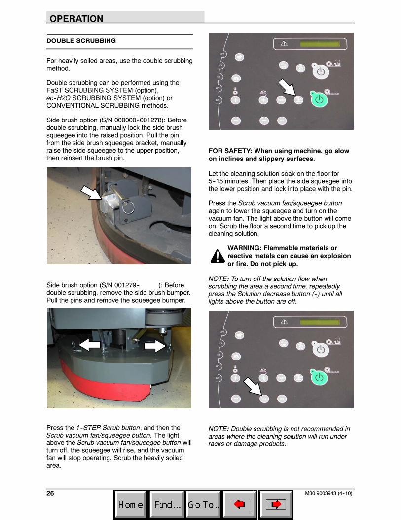
Side brush option (S/N 000000--001278): Beforedouble scrubbing, manually lock the side brushsqueegee into the raised position. Pull the pinfrom the side brush squeegee bracket, manuallyraise the side squeegee to the upper position,then reinsert the brush pin.
Side brush option (S/N 001279-- ): Beforedouble scrubbing, remove the side brush bumper.Pull the pins and remove the squeegee bumper.
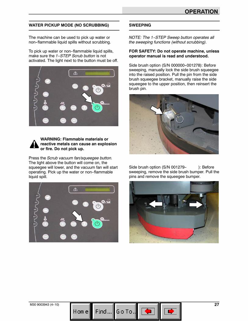
Press the 1--STEP Scrub button, and then theScrub vacuum fan/squeegee button. The lightabove the Scrub vacuum fan/squeegee button willturn off, the squeegee will rise, and the vacuumfan will stop operating. Scrub the heavily soiledarea.
FOR SAFETY: When using machine, go slowon inclines and slippery surfaces.
Let the cleaning solution soak on the floor for5--15 minutes. Then place the side squeegee intothe lower position and lock into place with the pin.
Press the Scrub vacuum fan/squeegee buttonagain to lower the squeegee and turn on thevacuum fan. The light above the button will comeon. Scrub the floor a second time to pick up thecleaning solution.
WARNING: Flammable materials orreactive metals can cause an explosionor fire. Do not pick up.
NOTE: To turn off the solution flow whenscrubbing the area a second time, repeatedlypress the Solution decrease button (--) until alllights above the button are off.
NOTE: Double scrubbing is not recommended inareas where the cleaning solution will run underracks or damage products.
OPERATION
27M30 9003943 (4--10)
WATER PICKUP MODE (NO SCRUBBING)
The machine can be used to pick up water ornon--flammable liquid spills without scrubbing.
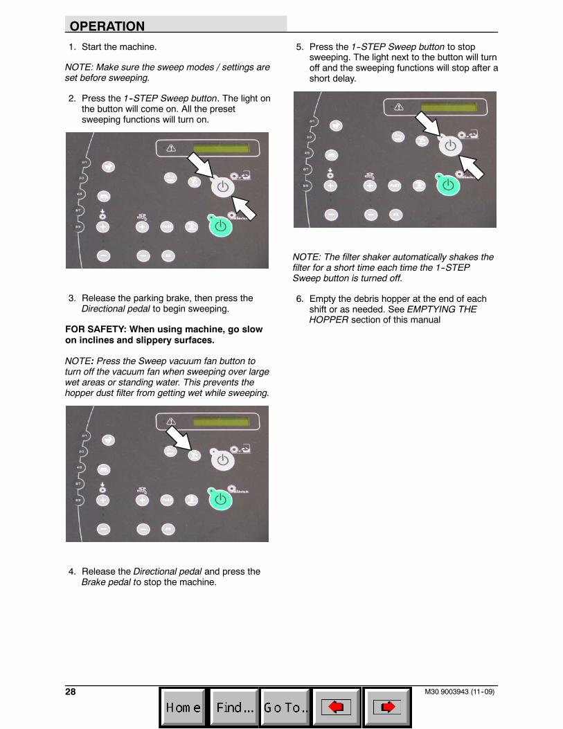
To pick up water or non--flammable liquid spills,make sure the 1--STEP Scrub button is notactivated. The light next to the button must be off.
WARNING: Flammable materials orreactive metals can cause an explosionor fire. Do not pick up.
Press the Scrub vacuum fan/squeegee button.The light above the button will come on, thesqueegee will lower, and the vacuum fan will startoperating. Pick up the water or non--flammableliquid spill.
SWEEPING
NOTE: The 1--STEP Sweep button operates allthe sweeping functions (without scrubbing).
FOR SAFETY: Do not operate machine, unlessoperator manual is read and understood.
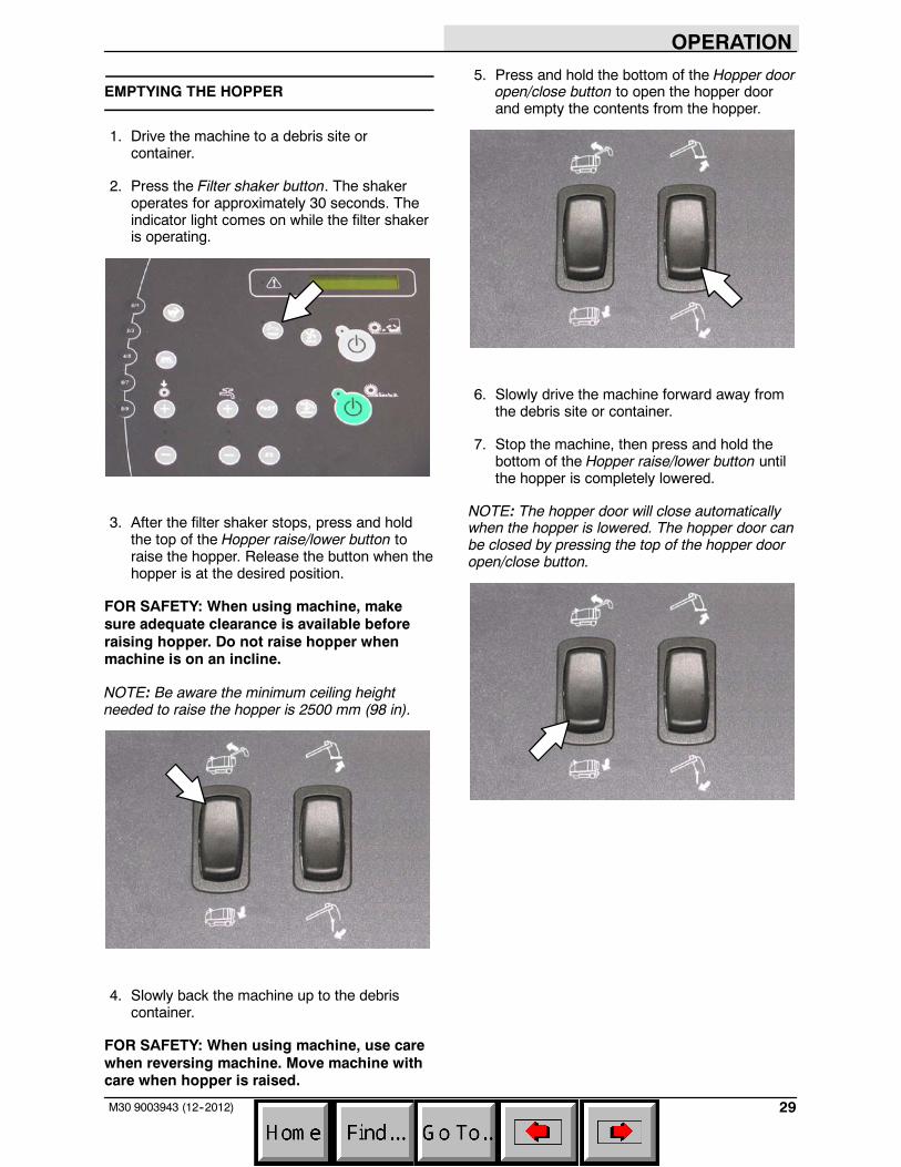
Side brush option (S/N 000000--001278): Beforesweeping, manually lock the side brush squeegeeinto the raised position. Pull the pin from the sidebrush squeegee bracket, manually raise the sidesqueegee to the upper position, then reinsert thebrush pin.
Side brush option (S/N 001279-- ): Beforesweeping, remove the side brush bumper. Pull thepins and remove the squeegee bumper.
OPERATION
28 M30 9003943 (11--09)
1. Start the machine.
NOTE: Make sure the sweep modes / settings areset before sweeping.
2. Press the 1--STEP Sweep button. The light onthe button will come on. All the presetsweeping functions will turn on.
3. Release the parking brake, then press theDirectional pedal to begin sweeping.
FOR SAFETY: When using machine, go slowon inclines and slippery surfaces.
NOTE: Press the Sweep vacuum fan button toturn off the vacuum fan when sweeping over largewet areas or standing water. This prevents thehopper dust filter from getting wet while sweeping.
4. Release the Directional pedal and press theBrake pedal to stop the machine.
5. Press the 1--STEP Sweep button to stopsweeping. The light next to the button will turnoff and the sweeping functions will stop after ashort delay.
NOTE: The filter shaker automatically shakes thefilter for a short time each time the 1--STEPSweep button is turned off.
6. Empty the debris hopper at the end of eachshift or as needed. See EMPTYING THEHOPPER section of this manual
OPERATION
29M30 9003943 (12--2012)
EMPTYING THE HOPPER
1. Drive the machine to a debris site orcontainer.
2. Press the Filter shaker button. The shakeroperates for approximately 30 seconds. Theindicator light comes on while the filter shakeris operating.
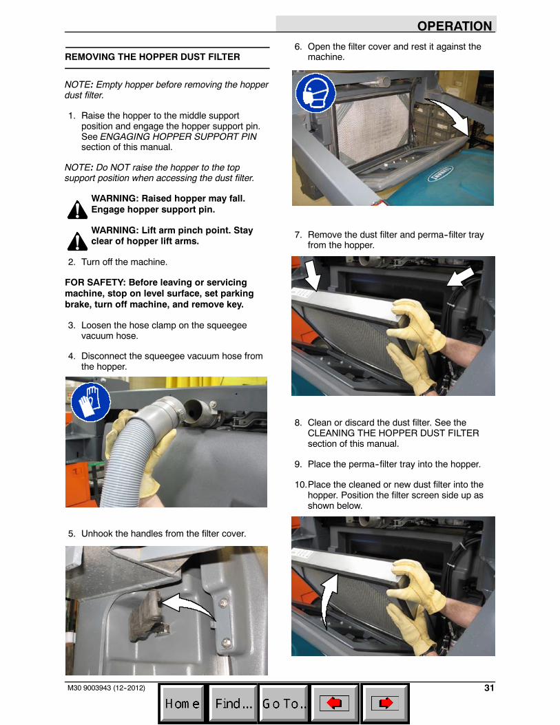
3. After the filter shaker stops, press and holdthe top of the Hopper raise/lower button toraise the hopper. Release the button when thehopper is at the desired position.
FOR SAFETY: When using machine, makesure adequate clearance is available beforeraising hopper. Do not raise hopper whenmachine is on an incline.
NOTE: Be aware the minimum ceiling heightneeded to raise the hopper is 2500 mm (98 in).
4. Slowly back the machine up to the debriscontainer.
FOR SAFETY: When using machine, use carewhen reversing machine. Move machine withcare when hopper is raised.
5. Press and hold the bottom of the Hopper dooropen/close button to open the hopper doorand empty the contents from the hopper.
6. Slowly drive the machine forward away fromthe debris site or container.
7. Stop the machine, then press and hold thebottom of the Hopper raise/lower button untilthe hopper is completely lowered.
NOTE: The hopper door will close automaticallywhen the hopper is lowered. The hopper door canbe closed by pressing the top of the hopper dooropen/close button.
OPERATION
30 M30 9003943 (1--08)
ENGAGING HOPPER SUPPORT PIN
The hopper support pin is a safety feature used toprevent the raised hopper from falling. Always usethe hopper support pin whenever leaving thehopper in a raised position.
1. Stop the machine.
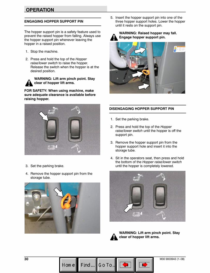
2. Press and hold the top of the Hopperraise/lower switch to raise the hopper.Release the switch when the hopper is at thedesired position.
WARNING: Lift arm pinch point. Stayclear of hopper lift arms.
FOR SAFETY: When using machine, makesure adequate clearance is available beforeraising hopper.
3. Set the parking brake.
4. Remove the hopper support pin from thestorage tube.
5. Insert the hopper support pin into one of thethree hopper support holes. Lower the hopperuntil it rests on the support pin.
WARNING: Raised hopper may fall.Engage hopper support pin.
DISENGAGING HOPPER SUPPORT PIN
1. Set the parking brake.
2. Press and hold the top of the Hopperraise/lower switch until the hopper is off thesupport pin.
3. Remove the hopper support pin from thehopper support hole and insert it into thestorage tube.
4. Sit in the operators seat, then press and holdthe bottom of the Hopper raise/lower switchuntil the hopper is completely lowered.
WARNING: Lift arm pinch point. Stayclear of hopper lift arms.
OPERATION
31M30 9003943 (12--2012)
REMOVING THE HOPPER DUST FILTER
NOTE: Empty hopper before removing the hopperdust filter.
1. Raise the hopper to the middle supportposition and engage the hopper support pin.See ENGAGING HOPPER SUPPORT PINsection of this manual.
NOTE: Do NOT raise the hopper to the topsupport position when accessing the dust filter.
WARNING: Raised hopper may fall.Engage hopper support pin.
WARNING: Lift arm pinch point. Stayclear of hopper lift arms.
2. Turn off the machine.
FOR SAFETY: Before leaving or servicingmachine, stop on level surface, set parkingbrake, turn off machine, and remove key.
3. Loosen the hose clamp on the squeegeevacuum hose.
4. Disconnect the squeegee vacuum hose fromthe hopper.
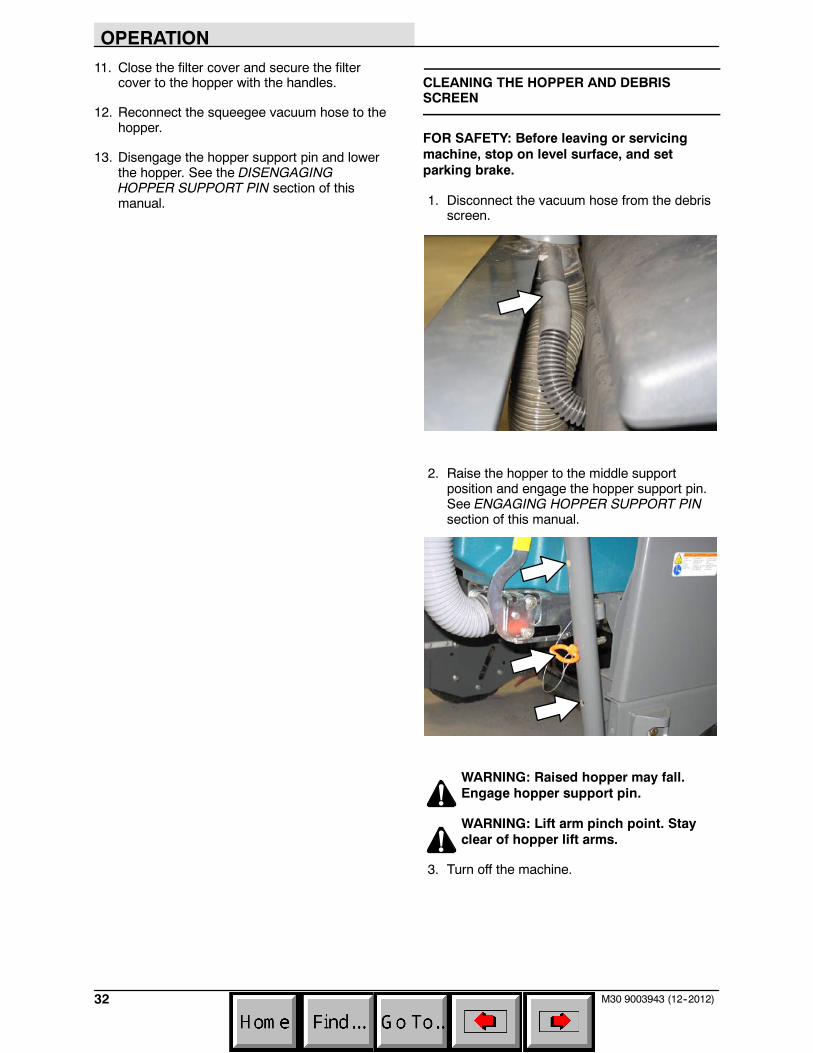
5. Unhook the handles from the filter cover.
6. Open the filter cover and rest it against themachine.
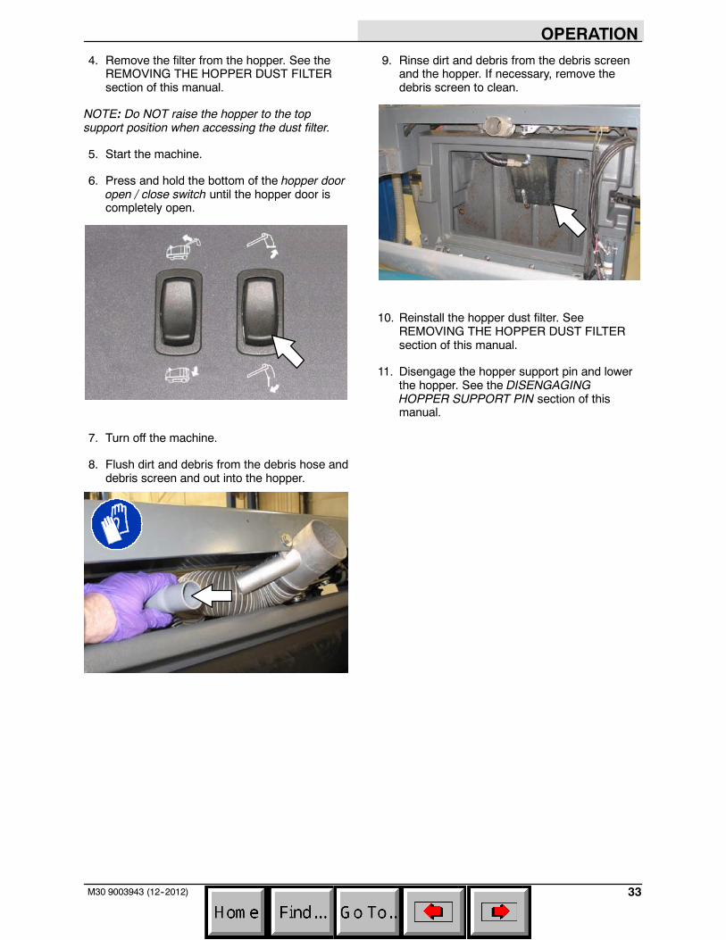
7. Remove the dust filter and perma--filter trayfrom the hopper.
8. Clean or discard the dust filter. See theCLEANING THE HOPPER DUST FILTERsection of this manual.
9. Place the perma--filter tray into the hopper.
10.Place the cleaned or new dust filter into thehopper. Position the filter screen side up asshown below.
OPERATION
32 M30 9003943 (12--2012)
11. Close the filter cover and secure the filtercover to the hopper with the handles.
12. Reconnect the squeegee vacuum hose to thehopper.
13. Disengage the hopper support pin and lowerthe hopper. See the DISENGAGINGHOPPER SUPPORT PIN section of thismanual.
CLEANING THE HOPPER AND DEBRISSCREEN
FOR SAFETY: Before leaving or servicingmachine, stop on level surface, and setparking brake.
1. Disconnect the vacuum hose from the debrisscreen.
2. Raise the hopper to the middle supportposition and engage the hopper support pin.See ENGAGING HOPPER SUPPORT PINsection of this manual.
WARNING: Raised hopper may fall.Engage hopper support pin.
WARNING: Lift arm pinch point. Stayclear of hopper lift arms.
3. Turn off the machine.
OPERATION
33M30 9003943 (12--2012)
4. Remove the filter from the hopper. See theREMOVING THE HOPPER DUST FILTERsection of this manual.
NOTE: Do NOT raise the hopper to the topsupport position when accessing the dust filter.
5. Start the machine.
6. Press and hold the bottom of the hopper dooropen / close switch until the hopper door iscompletely open.
7. Turn off the machine.
8. Flush dirt and debris from the debris hose anddebris screen and out into the hopper.
9. Rinse dirt and debris from the debris screenand the hopper. If necessary, remove thedebris screen to clean.
10. Reinstall the hopper dust filter. SeeREMOVING THE HOPPER DUST FILTERsection of this manual.
11. Disengage the hopper support pin and lowerthe hopper. See the DISENGAGINGHOPPER SUPPORT PIN section of thismanual.
OPERATION
34 M30 9003943 (12--2012)
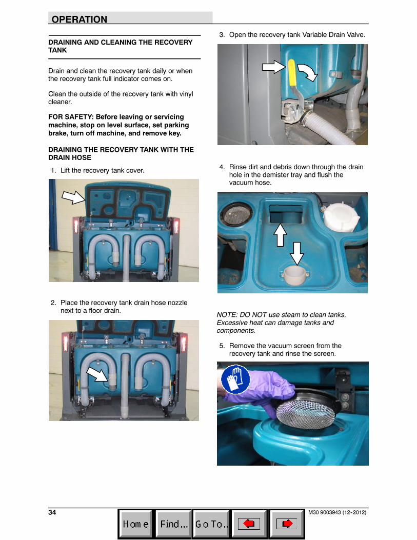
DRAINING AND CLEANING THE RECOVERYTANK
Drain and clean the recovery tank daily or whenthe recovery tank full indicator comes on.
Clean the outside of the recovery tank with vinylcleaner.
FOR SAFETY: Before leaving or servicingmachine, stop on level surface, set parkingbrake, turn off machine, and remove key.
DRAINING THE RECOVERY TANK WITH THEDRAIN HOSE
1. Lift the recovery tank cover.
2. Place the recovery tank drain hose nozzlenext to a floor drain.
3. Open the recovery tank Variable Drain Valve.
4. Rinse dirt and debris down through the drainhole in the demister tray and flush thevacuum hose.
NOTE: DO NOT use steam to clean tanks.Excessive heat can damage tanks andcomponents.
5. Remove the vacuum screen from therecovery tank and rinse the screen.
OPERATION
35M30 9003943 (12--2012)
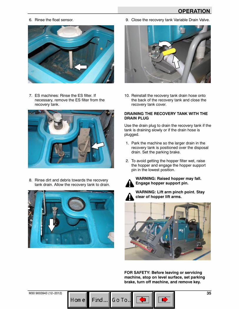
6. Rinse the float sensor.
7. ES machines: Rinse the ES filter. Ifnecessary, remove the ES filter from therecovery tank.
8. Rinse dirt and debris towards the recoverytank drain. Allow the recovery tank to drain.
9. Close the recovery tank Variable Drain Valve.
10. Reinstall the recovery tank drain hose ontothe back of the recovery tank and close therecovery tank cover.
DRAINING THE RECOVERY TANK WITH THEDRAIN PLUG
Use the drain plug to drain the recovery tank if thetank is draining slowly or if the drain hose isplugged.
1. Park the machine so the larger drain in therecovery tank is positioned over the disposaldrain. Set the parking brake.
2. To avoid getting the hopper filter wet, raisethe hopper and engage the hopper supportpin in the lowest position.
WARNING: Raised hopper may fall.Engage hopper support pin.
WARNING: Lift arm pinch point. Stayclear of hopper lift arms.
FOR SAFETY: Before leaving or servicingmachine, stop on level surface, set parkingbrake, turn off machine, and remove key.
OPERATION
36 M30 9003943 (12--2012)
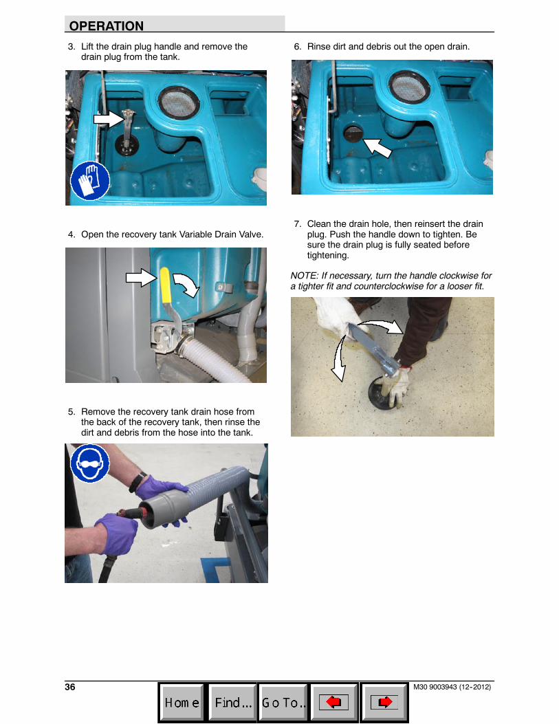
3. Lift the drain plug handle and remove thedrain plug from the tank.
4. Open the recovery tank Variable Drain Valve.
5. Remove the recovery tank drain hose fromthe back of the recovery tank, then rinse thedirt and debris from the hose into the tank.
6. Rinse dirt and debris out the open drain.
7. Clean the drain hole, then reinsert the drainplug. Push the handle down to tighten. Besure the drain plug is fully seated beforetightening.
NOTE: If necessary, turn the handle clockwise fora tighter fit and counterclockwise for a looser fit.
OPERATION
37M30 9003943 (12--2012)
8. Close the recovery tank Variable Drain Valve.
9. Reinstall the recovery tank drain hose ontothe back of the recovery tank.
10. Remove the hopper support pin and insert itinto the storage tube. Then lower the hopper.
11. Close the recovery tank cover.
DRAINING AND CLEANING THE SOLUTIONTANK
The solution tank on non--ES machines does notrequire regular maintenance. If deposits form onthe bottom of the tank, rinse the tank with astrong blast of warm water.
Clean the outside of the solution tank with vinylcleaner.
The solution tank on machines with the ES optionshould be drained and cleaned daily.
FOR SAFETY: Before leaving or servicingmachine, stop on level surface, set parkingbrake, turn off machine, and remove key.
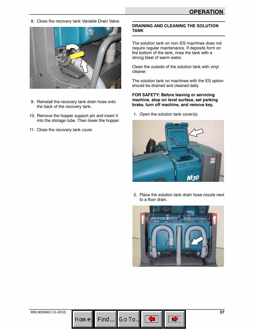
1. Open the solution tank cover(s).
2. Place the solution tank drain hose nozzle nextto a floor drain.
OPERATION
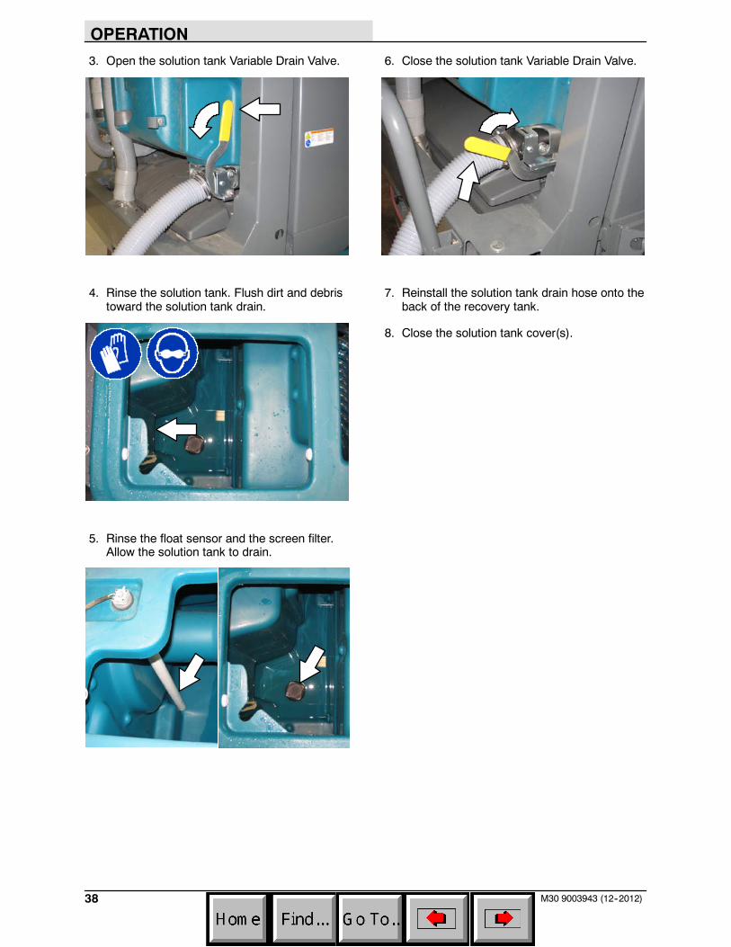
38 M30 9003943 (12--2012)
3. Open the solution tank Variable Drain Valve.
4. Rinse the solution tank. Flush dirt and debristoward the solution tank drain.
5. Rinse the float sensor and the screen filter.Allow the solution tank to drain.
6. Close the solution tank Variable Drain Valve.
7. Reinstall the solution tank drain hose onto theback of the recovery tank.
8. Close the solution tank cover(s).
OPERATION
39M30 9003943 (12--2012)
FAULT INDICATOR(S)
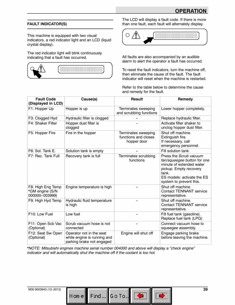
This machine is equipped with two visualindicators, a red indicator light and an LCD (liquidcrystal display).
The red indicator light will blink continuouslyindicating that a fault has occurred.
The LCD will display a fault code. If there is morethan one fault, each fault will alternately display.
All faults are also accompanied by an audiblealarm to alert the operator a fault has occurred.
To reset the fault indicators, turn the machine off,then eliminate the cause of the fault. The faultindicator will reset when the machine is restarted.
Refer to the table below to determine the causeand remedy for the fault.
Fault Code(Displayed in LCD)
Cause(s) Result Remedy
F1: Hopper Up Hopper is up Terminates sweepingand scrubbing functions
Lower hopper completely.
F3: Clogged Hyd Hydraulic filter is clogged -- Replace hydraulic filter.F4: Shaker Filter Hopper dust filter is
clogged-- Activate filter shaker to
unclog hopper dust filter.F5: Hopper Fire Fire in the hopper Terminates sweeping
functions and closeshopper door
Shut off machine.Extinguish fire.If necessary, callemergency personnel.
F6: Sol. Tank E. Solution tank is empty -- Fill solution tank.F7: Rec. Tank Full Recovery tank is full Terminates scrubbing
functionsPress the Scrub vacuumfan/squeegee button for oneminute of extended waterpickup. Empty recoverytank.ES models: activate the ESsystem to prevent this.
F8: High Eng Temp*GM engine (S/N000000--003999)
Engine temperature is high -- Shut off machine.Contact TENNANT servicerepresentative.
F9: High Hyd Temp Hydraulic fluid temperatureis high
-- Shut off machine.Contact TENNANT servicerepresentative.
F10: Low Fuel Low fuel -- Fill fuel tank (gasoline).Replace fuel tank (LPG)
F11: Open Scb Vac(Optional)
Scrub vacuum hose is notconnected
-- Connect vacuum hose tosqueegee assembly.
F12: Seat Sw Open(Optional)
Operator not in the seatwhile engine is running andparking brake not engaged
Engine will shut off Engage parking brakebefore leaving the machine.
*NOTE: Mitsubishi engines machine serial number 004000 and above will display a “check engine”indicator and will automatically shut the machine off if the coolant is too hot.
OPERATION
40 M30 9003943 (1--08)
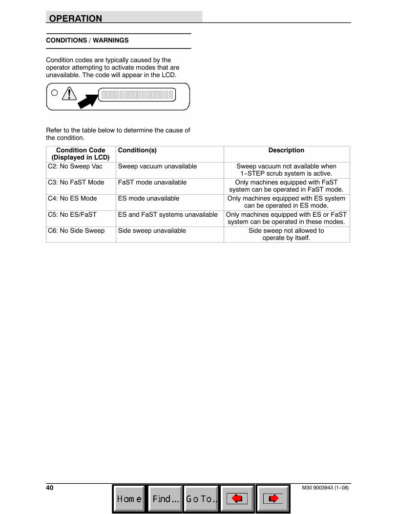
CONDITIONS / WARNINGS
Condition codes are typically caused by theoperator attempting to activate modes that areunavailable. The code will appear in the LCD.
Refer to the table below to determine the cause ofthe condition.
Condition Code(Displayed in LCD)
Condition(s) Description
C2: No Sweep Vac Sweep vacuum unavailable Sweep vacuum not available when1--STEP scrub system is active.
C3: No FaST Mode FaST mode unavailable Only machines equipped with FaSTsystem can be operated in FaST mode.
C4: No ES Mode ES mode unavailable Only machines equipped with ES systemcan be operated in ES mode.
C5: No ES/FaST ES and FaST systems unavailable Only machines equipped with ES or FaSTsystem can be operated in these modes.
C6: No Side Sweep Side sweep unavailable Side sweep not allowed tooperate by itself.
OPERATION
41M30 9003943 (12--2012)
OPTIONS
SPRAY NOZZLE (OPTION)
The spray nozzle is used to clean the machineand surrounding areas. The solution tank providesa water/solution supply for the spray nozzle. Awand is included with the spray nozzle.
NOTE: Do NOT get water on electroniccomponents when using the spray nozzle to cleanthe machine.
FOR SAFETY: Before leaving or servicingmachine, stop on level surface, set parkingbrake, and turn off machine.
1. Turn the key to the on position (withoutstarting the machine).
NOTE: The spray nozzle can be operated whilethe engine is running, but it is recommended toturn the engine off while using the spray nozzle.
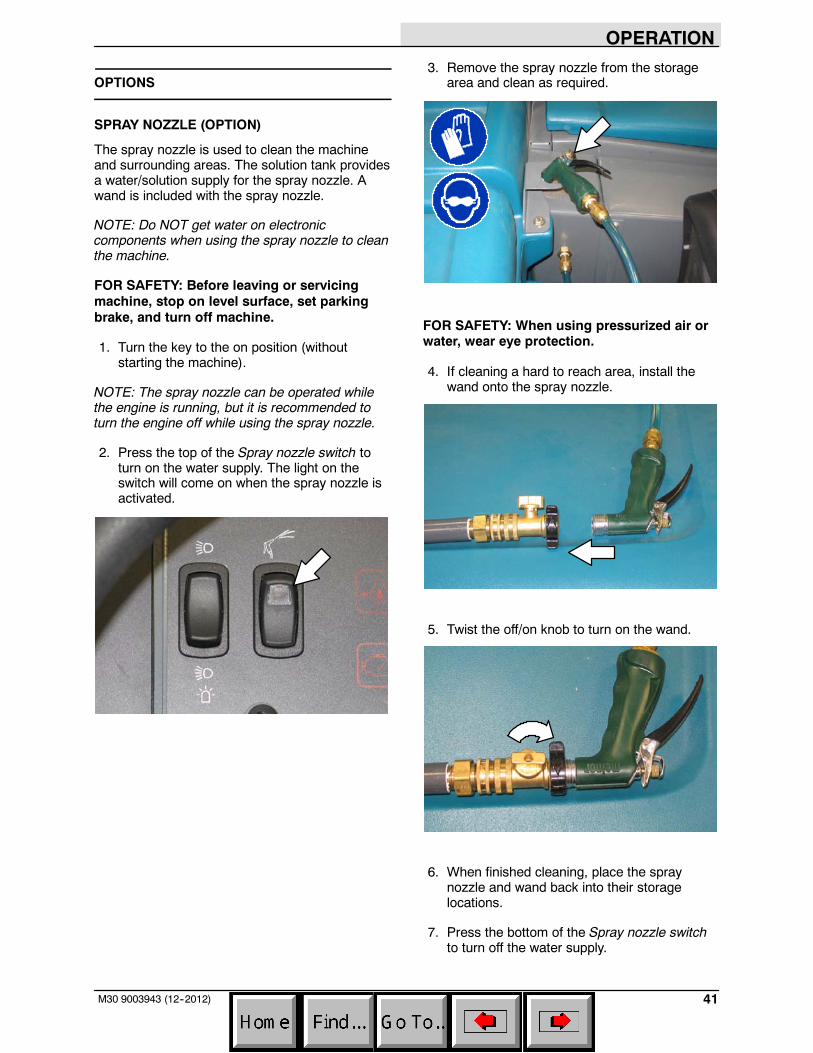
2. Press the top of the Spray nozzle switch toturn on the water supply. The light on theswitch will come on when the spray nozzle isactivated.
3. Remove the spray nozzle from the storagearea and clean as required.
FOR SAFETY: When using pressurized air orwater, wear eye protection.
4. If cleaning a hard to reach area, install thewand onto the spray nozzle.
5. Twist the off/on knob to turn on the wand.
6. When finished cleaning, place the spraynozzle and wand back into their storagelocations.
7. Press the bottom of the Spray nozzle switchto turn off the water supply.
OPERATION
42 M30 9003943 (12--2012)
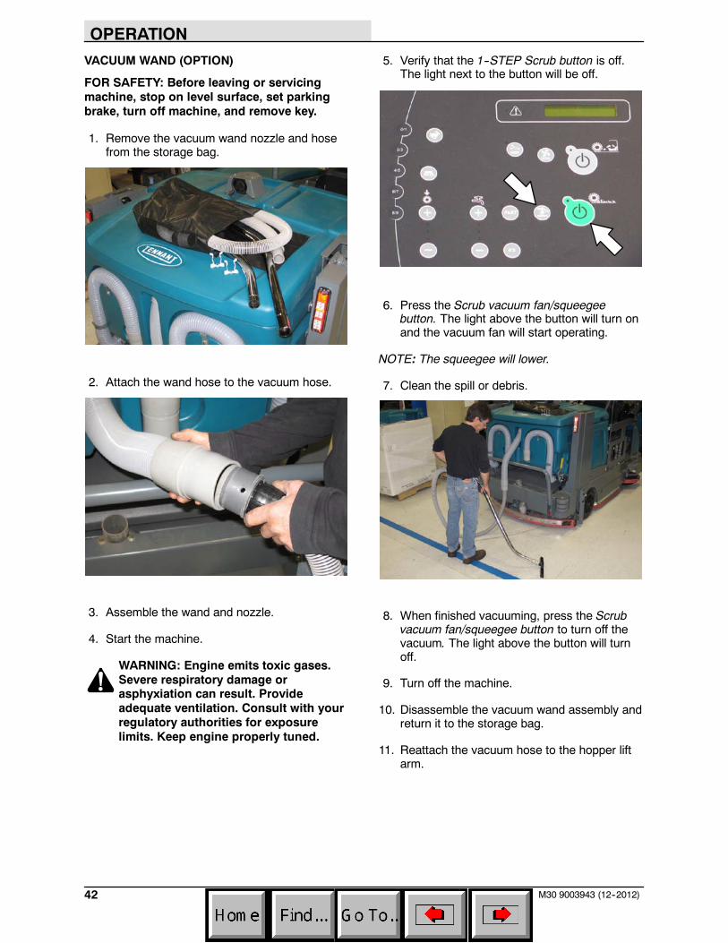
VACUUM WAND (OPTION)
FOR SAFETY: Before leaving or servicingmachine, stop on level surface, set parkingbrake, turn off machine, and remove key.
1. Remove the vacuum wand nozzle and hosefrom the storage bag.
2. Attach the wand hose to the vacuum hose.
3. Assemble the wand and nozzle.
4. Start the machine.
WARNING: Engine emits toxic gases.Severe respiratory damage orasphyxiation can result. Provideadequate ventilation. Consult with yourregulatory authorities for exposurelimits. Keep engine properly tuned.
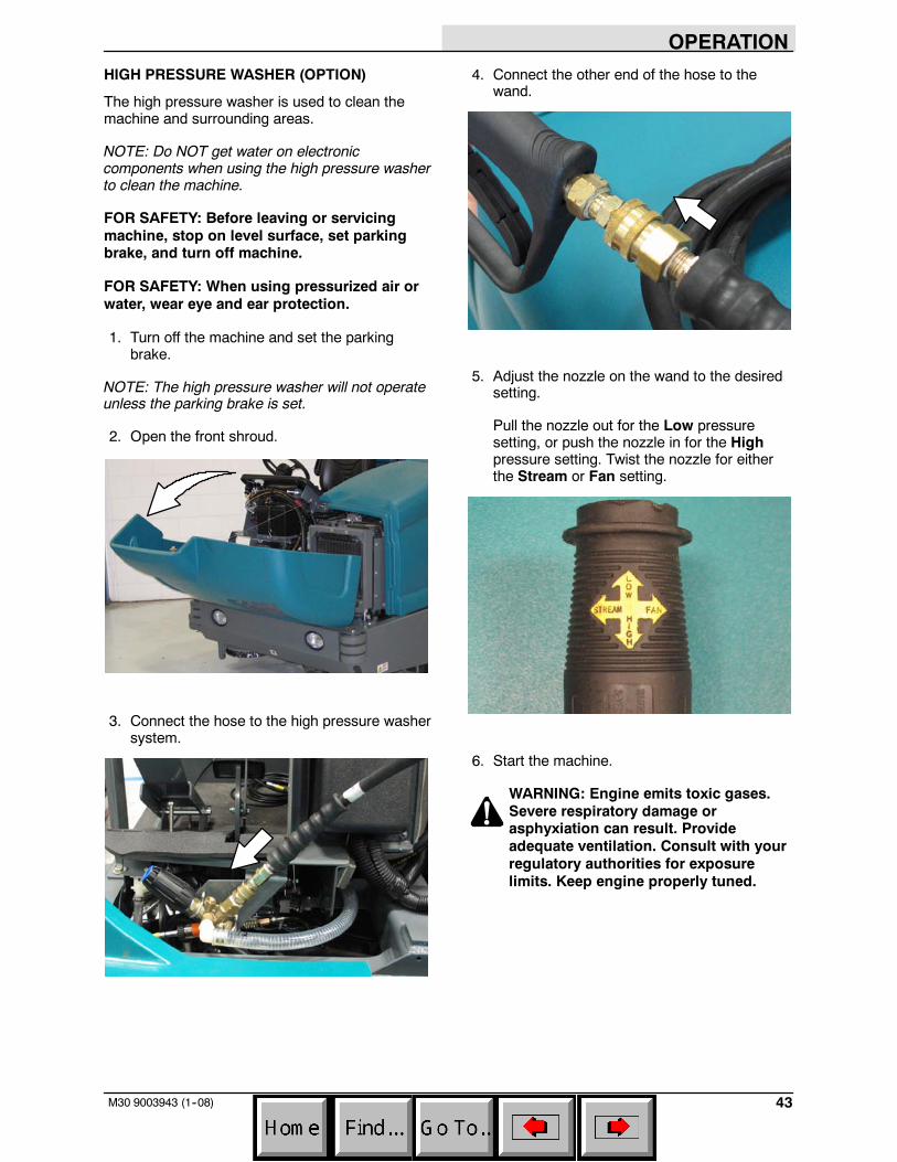
5. Verify that the 1--STEP Scrub button is off.The light next to the button will be off.
6. Press the Scrub vacuum fan/squeegeebutton. The light above the button will turn onand the vacuum fan will start operating.
NOTE: The squeegee will lower.
7. Clean the spill or debris.
8. When finished vacuuming, press the Scrubvacuum fan/squeegee button to turn off thevacuum. The light above the button will turnoff.
9. Turn off the machine.
10. Disassemble the vacuum wand assembly andreturn it to the storage bag.
11. Reattach the vacuum hose to the hopper liftarm.
OPERATION
43M30 9003943 (1--08)
HIGH PRESSURE WASHER (OPTION)
The high pressure washer is used to clean themachine and surrounding areas.
NOTE: Do NOT get water on electroniccomponents when using the high pressure washerto clean the machine.
FOR SAFETY: Before leaving or servicingmachine, stop on level surface, set parkingbrake, and turn off machine.
FOR SAFETY: When using pressurized air orwater, wear eye and ear protection.
1. Turn off the machine and set the parkingbrake.
NOTE: The high pressure washer will not operateunless the parking brake is set.
2. Open the front shroud.
3. Connect the hose to the high pressure washersystem.
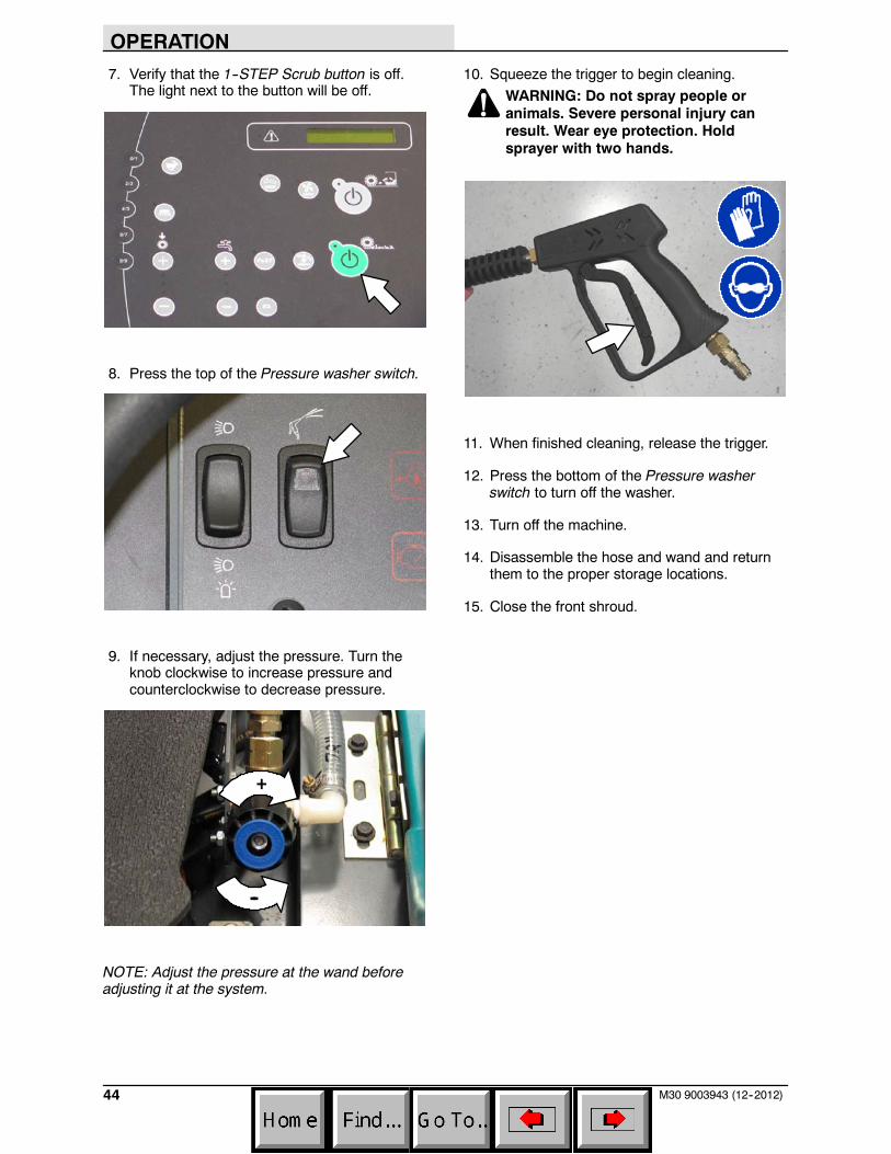
4. Connect the other end of the hose to thewand.
5. Adjust the nozzle on the wand to the desiredsetting.
Pull the nozzle out for the Low pressuresetting, or push the nozzle in for the Highpressure setting. Twist the nozzle for eitherthe Stream or Fan setting.
6. Start the machine.
WARNING: Engine emits toxic gases.Severe respiratory damage orasphyxiation can result. Provideadequate ventilation. Consult with yourregulatory authorities for exposurelimits. Keep engine properly tuned.
OPERATION
44 M30 9003943 (12--2012)
7. Verify that the 1--STEP Scrub button is off.The light next to the button will be off.
8. Press the top of the Pressure washer switch.
9. If necessary, adjust the pressure. Turn theknob clockwise to increase pressure andcounterclockwise to decrease pressure.
+
--
NOTE: Adjust the pressure at the wand beforeadjusting it at the system.
10. Squeeze the trigger to begin cleaning.
WARNING: Do not spray people oranimals. Severe personal injury canresult. Wear eye protection. Holdsprayer with two hands.
11. When finished cleaning, release the trigger.
12. Press the bottom of the Pressure washerswitch to turn off the washer.
13. Turn off the machine.
14. Disassemble the hose and wand and returnthem to the proper storage locations.
15. Close the front shroud.
OPERATION
45M30 9003943 (1--08)
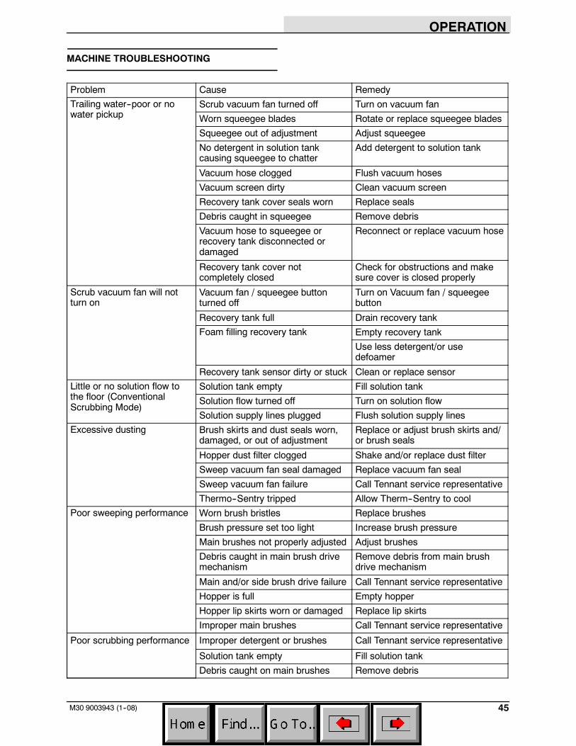
MACHINE TROUBLESHOOTING
Problem Cause Remedy
Trailing water--poor or nowater pickup
Scrub vacuum fan turned off Turn on vacuum fan
Worn squeegee blades Rotate or replace squeegee blades
Squeegee out of adjustment Adjust squeegee
No detergent in solution tankcausing squeegee to chatter
Add detergent to solution tank
Vacuum hose clogged Flush vacuum hoses
Vacuum screen dirty Clean vacuum screen
Recovery tank cover seals worn Replace seals
Debris caught in squeegee Remove debris
Vacuum hose to squeegee orrecovery tank disconnected ordamaged
Reconnect or replace vacuum hose
Recovery tank cover notcompletely closed
Check for obstructions and makesure cover is closed properly
Scrub vacuum fan will notturn on
Vacuum fan / squeegee buttonturned off
Turn on Vacuum fan / squeegeebutton
Recovery tank full Drain recovery tank
Foam filling recovery tank Empty recovery tank
Use less detergent/or usedefoamer
Recovery tank sensor dirty or stuck Clean or replace sensor
Little or no solution flow tothe floor (ConventionalScrubbing Mode)
Solution tank empty Fill solution tank
Solution flow turned off Turn on solution flow
Solution supply lines plugged Flush solution supply lines
Excessive dusting Brush skirts and dust seals worn,damaged, or out of adjustment
Replace or adjust brush skirts and/or brush seals
Hopper dust filter clogged Shake and/or replace dust filter
Sweep vacuum fan seal damaged Replace vacuum fan seal
Sweep vacuum fan failure Call Tennant service representative
Thermo--Sentry tripped Allow Therm--Sentry to cool
Poor sweeping performance Worn brush bristles Replace brushes
Brush pressure set too light Increase brush pressure
Main brushes not properly adjusted Adjust brushes
Debris caught in main brush drivemechanism
Remove debris from main brushdrive mechanism
Main and/or side brush drive failure Call Tennant service representative
Hopper is full Empty hopper
Hopper lip skirts worn or damaged Replace lip skirts
Improper main brushes Call Tennant service representative
Poor scrubbing performance Improper detergent or brushes Call Tennant service representative
Solution tank empty Fill solution tank
Debris caught on main brushes Remove debris
OPERATION
46 M30 9003943 (10--10)
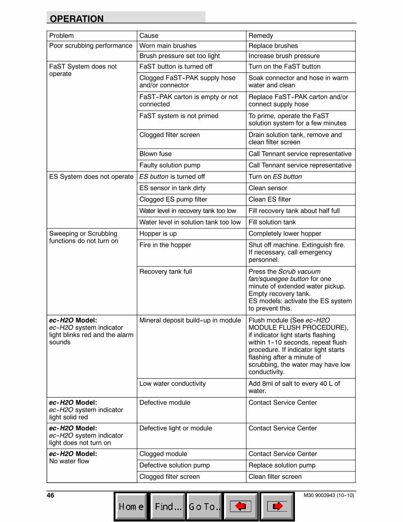
Problem Cause Remedy
Poor scrubbing performance Worn main brushes Replace brushes
Brush pressure set too light Increase brush pressure
FaST System does notoperate
FaST button is turned off Turn on the FaST button
Clogged FaST--PAK supply hoseand/or connector
Soak connector and hose in warmwater and clean
FaST--PAK carton is empty or notconnected
Replace FaST--PAK carton and/orconnect supply hose
FaST system is not primed To prime, operate the FaSTsolution system for a few minutes
Clogged filter screen Drain solution tank, remove andclean filter screen
Blown fuse Call Tennant service representative
Faulty solution pump Call Tennant service representative
ES System does not operate ES button is turned off Turn on ES button
ES sensor in tank dirty Clean sensor
Clogged ES pump filter Clean ES filter
Water level in recovery tank too low Fill recovery tank about half full
Water level in solution tank too low Fill solution tank
Sweeping or Scrubbingfunctions do not turn on
Hopper is up Completely lower hopper
Fire in the hopper Shut off machine. Extinguish fire.If necessary, call emergencypersonnel.
Recovery tank full Press the Scrub vacuumfan/squeegee button for oneminute of extended water pickup.Empty recovery tank.ES models: activate the ES systemto prevent this.
ec-H2O Model:ec--H2O system indicatorlight blinks red and the alarmsounds
Mineral deposit build--up in module Flush module (See ec--H2OMODULE FLUSH PROCEDURE),if indicator light starts flashingwithin 1--10 seconds, repeat flushprocedure. If indicator light startsflashing after a minute ofscrubbing, the water may have lowconductivity.
Low water conductivity Add 8ml of salt to every 40 L ofwater.
ec-H2O Model:ec--H2O system indicatorlight solid red
Defective module Contact Service Center
ec-H2O Model:ec--H2O system indicatorlight does not turn on
Defective light or module Contact Service Center
ec-H2O Model:No water flow
Clogged module Contact Service Center
Defective solution pump Replace solution pump
Clogged filter screen Clean filter screen
MAINTENANCE
47M30 9003943 (5--08)
MAINTENANCE
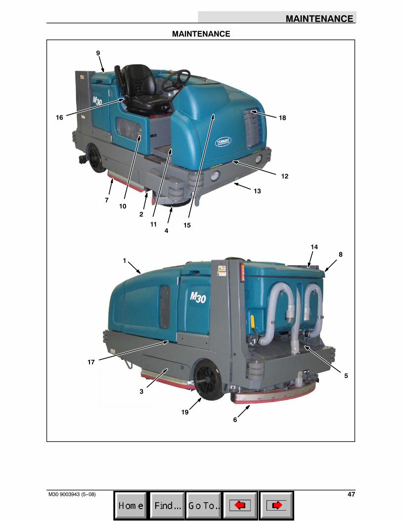
1
2
3
4
5
6
7
8
9
19
10
12
14
13
15
16
11
17
18
MAINTENANCE
48 M30 9003943 (12--2012)
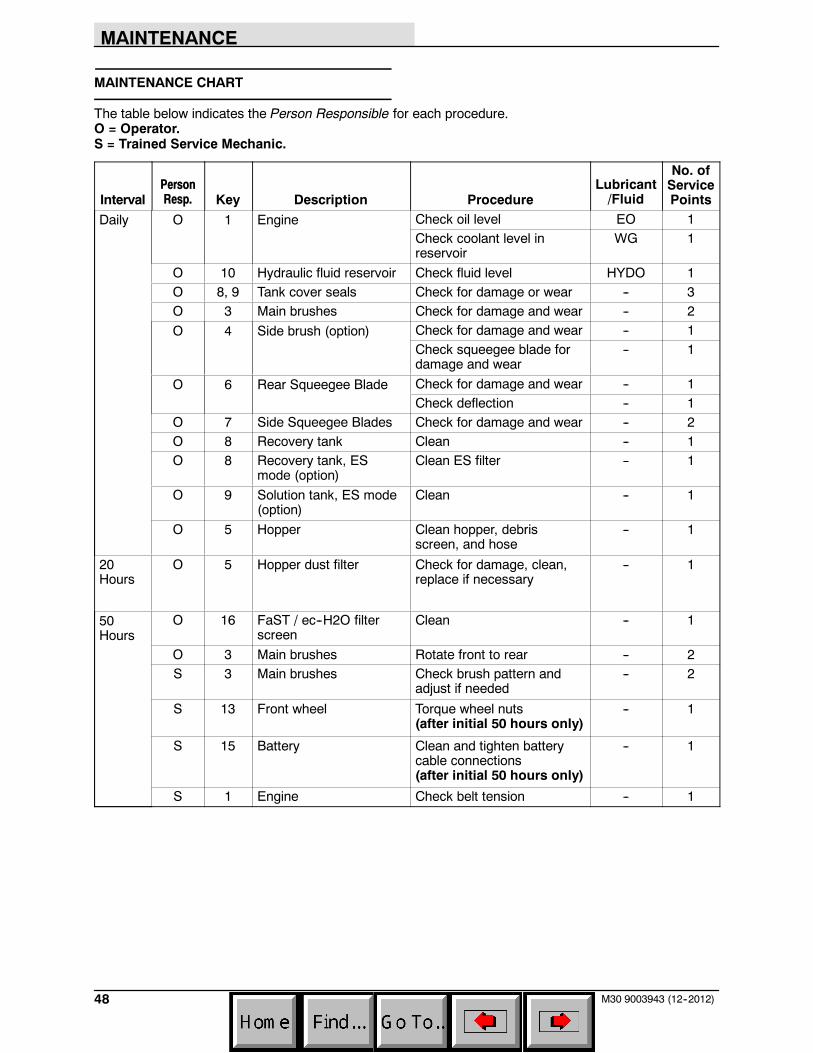
MAINTENANCE CHART
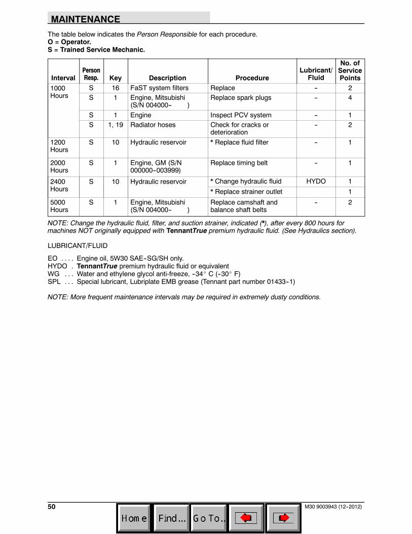
The table below indicates the Person Responsible for each procedure.O = Operator.S = Trained Service Mechanic.
IntervalPersonResp. Key Description Procedure
Lubricant/Fluid
No. ofServicePoints
Daily O 1 Engine Check oil level EO 1Check coolant level inreservoir
WG 1
O 10 Hydraulic fluid reservoir Check fluid level HYDO 1O 8, 9 Tank cover seals Check for damage or wear -- 3O 3 Main brushes Check for damage and wear -- 2
O 4 Side brush (option) Check for damage and wear -- 1Check squeegee blade fordamage and wear
-- 1
O 6 Rear Squeegee Blade Check for damage and wear -- 1Check deflection -- 1
O 7 Side Squeegee Blades Check for damage and wear -- 2O 8 Recovery tank Clean -- 1O 8 Recovery tank, ES
mode (option)Clean ES filter -- 1
O 9 Solution tank, ES mode(option)
Clean -- 1
O 5 Hopper Clean hopper, debrisscreen, and hose
-- 1
20Hours
O 5 Hopper dust filter Check for damage, clean,replace if necessary
-- 1
50Hours
O 16 FaST / ec--H2O filterscreen
Clean -- 1
O 3 Main brushes Rotate front to rear -- 2S 3 Main brushes Check brush pattern and
adjust if needed-- 2
S 13 Front wheel Torque wheel nuts(after initial 50 hours only)
-- 1
S 15 Battery Clean and tighten batterycable connections(after initial 50 hours only)
-- 1
S 1 Engine Check belt tension -- 1
MAINTENANCE
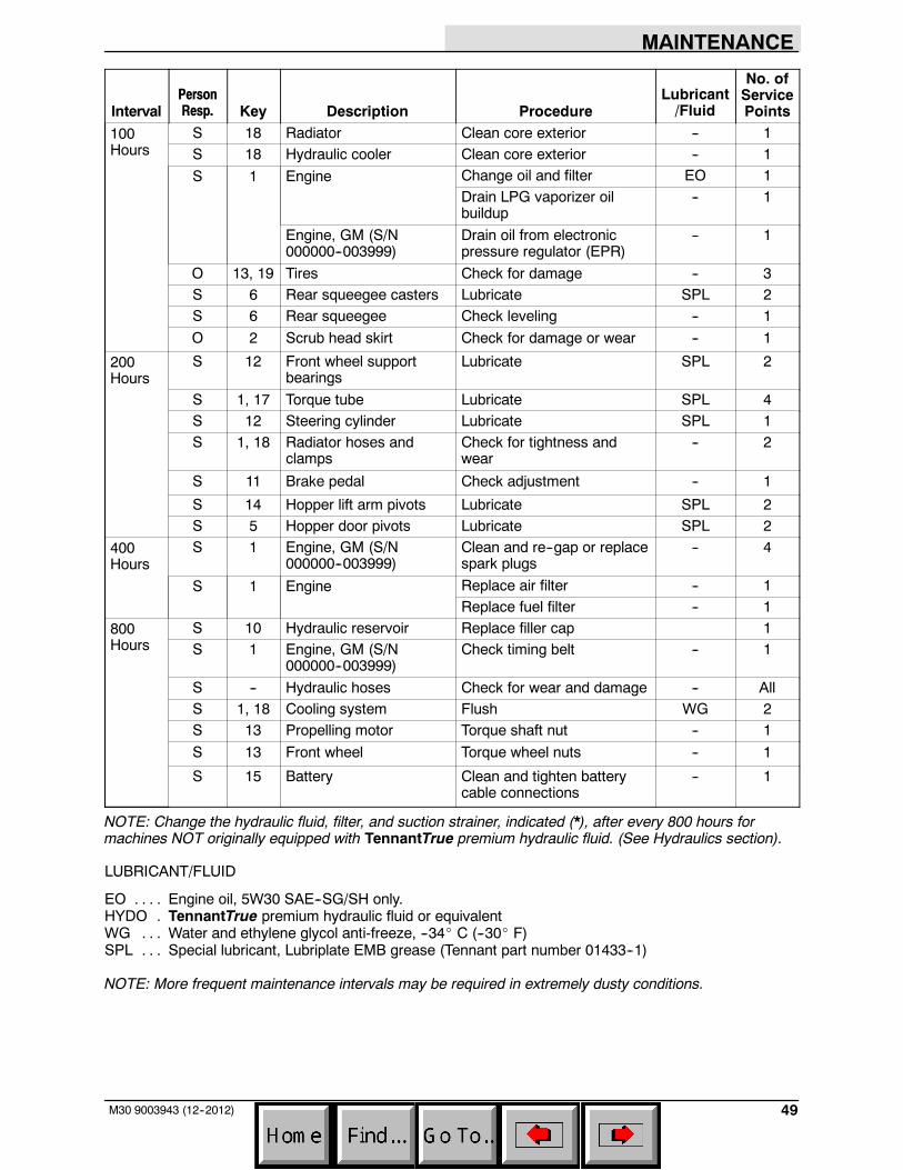
49M30 9003943 (12--2012)
IntervalPersonResp. Key Description Procedure
Lubricant/Fluid
No. ofServicePoints
100Hours
S 18 Radiator Clean core exterior -- 1S 18 Hydraulic cooler Clean core exterior -- 1
S 1 Engine Change oil and filter EO 1Drain LPG vaporizer oilbuildup
-- 1
Engine, GM (S/N000000--003999)
Drain oil from electronicpressure regulator (EPR)
-- 1
O 13, 19 Tires Check for damage -- 3S 6 Rear squeegee casters Lubricate SPL 2S 6 Rear squeegee Check leveling -- 1
O 2 Scrub head skirt Check for damage or wear -- 1
200Hours
S 12 Front wheel supportbearings
Lubricate SPL 2
S 1, 17 Torque tube Lubricate SPL 4S 12 Steering cylinder Lubricate SPL 1S 1, 18 Radiator hoses and
clampsCheck for tightness andwear
-- 2
S 11 Brake pedal Check adjustment -- 1
S 14 Hopper lift arm pivots Lubricate SPL 2S 5 Hopper door pivots Lubricate SPL 2
400Hours
S 1 Engine, GM (S/N000000--003999)
Clean and re--gap or replacespark plugs
-- 4
S 1 Engine Replace air filter -- 1Replace fuel filter -- 1
800Hours
S 10 Hydraulic reservoir Replace filler cap 1S 1 Engine, GM (S/N
000000--003999)Check timing belt -- 1
S -- Hydraulic hoses Check for wear and damage -- AllS 1, 18 Cooling system Flush WG 2S 13 Propelling motor Torque shaft nut -- 1
S 13 Front wheel Torque wheel nuts -- 1
S 15 Battery Clean and tighten batterycable connections
-- 1
NOTE: Change the hydraulic fluid, filter, and suction strainer, indicated (*), after every 800 hours formachines NOT originally equipped with TennantTrue premium hydraulic fluid. (See Hydraulics section).
LUBRICANT/FLUID
EO Engine oil, 5W30 SAE--SG/SH only.. . . .HYDO TennantTrue premium hydraulic fluid or equivalent.WG Water and ethylene glycol anti-freeze, --34_ C (--30_ F). . .SPL Special lubricant, Lubriplate EMB grease (Tennant part number 01433--1). . .
NOTE: More frequent maintenance intervals may be required in extremely dusty conditions.
MAINTENANCE
50 M30 9003943 (12--2012)
The table below indicates the Person Responsible for each procedure.O = Operator.S = Trained Service Mechanic.
IntervalPersonResp. Key Description Procedure
Lubricant/Fluid
No. ofServicePoints
1000Hours
S 16 FaST system filters Replace -- 2S 1 Engine, Mitsubishi
(S/N 004000-- )Replace spark plugs -- 4
S 1 Engine Inspect PCV system -- 1S 1, 19 Radiator hoses Check for cracks or
deterioration-- 2
1200Hours
S 10 Hydraulic reservoir * Replace fluid filter -- 1
2000Hours
S 1 Engine, GM (S/N000000--003999)
Replace timing belt -- 1
2400Hours
S 10 Hydraulic reservoir * Change hydraulic fluid HYDO 1
* Replace strainer outlet 1
5000Hours
S 1 Engine, Mitsubishi(S/N 004000-- )
Replace camshaft andbalance shaft belts
-- 2
NOTE: Change the hydraulic fluid, filter, and suction strainer, indicated (*), after every 800 hours formachines NOT originally equipped with TennantTrue premium hydraulic fluid. (See Hydraulics section).
LUBRICANT/FLUID
EO Engine oil, 5W30 SAE--SG/SH only.. . . .HYDO TennantTrue premium hydraulic fluid or equivalent.WG Water and ethylene glycol anti-freeze, --34_ C (--30_ F). . .SPL Special lubricant, Lubriplate EMB grease (Tennant part number 01433--1). . .
NOTE: More frequent maintenance intervals may be required in extremely dusty conditions.
MAINTENANCE
51M30 9003943 (12--2012)
LUBRICATION
FOR SAFETY: Before leaving or servicingmachine, stop on level surface, set parkingbrake, turn off machine, and remove key.
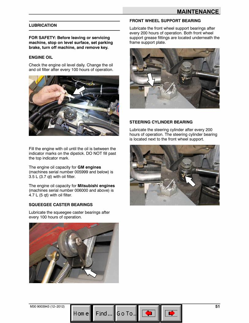
ENGINE OIL
Check the engine oil level daily. Change the oiland oil filter after every 100 hours of operation.
Fill the engine with oil until the oil is between theindicator marks on the dipstick. DO NOT fill pastthe top indicator mark.
The engine oil capacity for GM engines(machines serial number 005999 and below) is3.5 L (3.7 qt) with oil filter.
The engine oil capacity for Mitsubishi engines(machines serial number 006000 and above) is4.7 L (5 qt) with oil filter.
SQUEEGEE CASTER BEARINGS
Lubricate the squeegee caster bearings afterevery 100 hours of operation.
FRONT WHEEL SUPPORT BEARING
Lubricate the front wheel support bearings afterevery 200 hours of operation. Both front wheelsupport grease fittings are located underneath theframe support plate.
STEERING CYLINDER BEARING
Lubricate the steering cylinder after every 200hours of operation. The steering cylinder bearingis located next to the front wheel support.
MAINTENANCE
52 M30 9003943 (1--08)
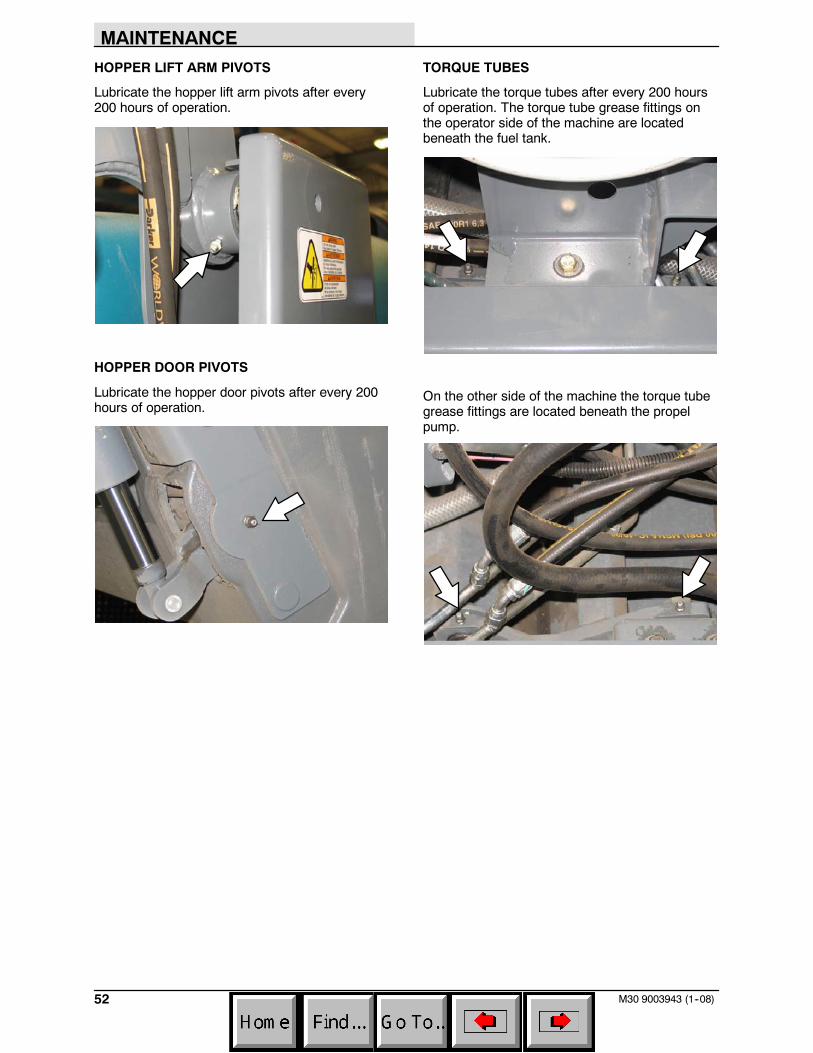
HOPPER LIFT ARM PIVOTS
Lubricate the hopper lift arm pivots after every200 hours of operation.
HOPPER DOOR PIVOTS
Lubricate the hopper door pivots after every 200hours of operation.
TORQUE TUBES
Lubricate the torque tubes after every 200 hoursof operation. The torque tube grease fittings onthe operator side of the machine are locatedbeneath the fuel tank.
On the other side of the machine the torque tubegrease fittings are located beneath the propelpump.
MAINTENANCE
53M30 9003943 (12--2012)
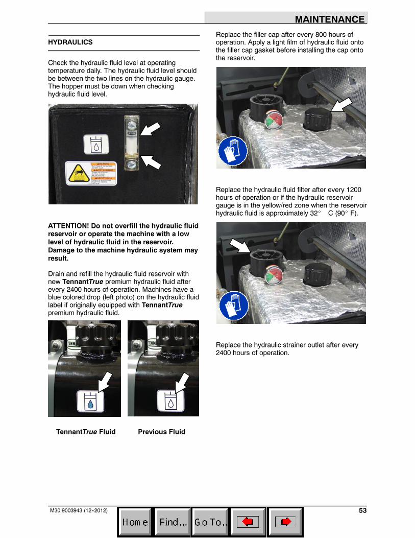
HYDRAULICS
Check the hydraulic fluid level at operatingtemperature daily. The hydraulic fluid level shouldbe between the two lines on the hydraulic gauge.The hopper must be down when checkinghydraulic fluid level.
ATTENTION! Do not overfill the hydraulic fluidreservoir or operate the machine with a lowlevel of hydraulic fluid in the reservoir.Damage to the machine hydraulic system mayresult.
Drain and refill the hydraulic fluid reservoir withnew TennantTrue premium hydraulic fluid afterevery 2400 hours of operation. Machines have ablue colored drop (left photo) on the hydraulic fluidlabel if originally equipped with TennantTruepremium hydraulic fluid.
TennantTrue Fluid Previous Fluid
Replace the filler cap after every 800 hours ofoperation. Apply a light film of hydraulic fluid ontothe filler cap gasket before installing the cap ontothe reservoir.
Replace the hydraulic fluid filter after every 1200hours of operation or if the hydraulic reservoirgauge is in the yellow/red zone when the reservoirhydraulic fluid is approximately 32_ C (90_ F).
Replace the hydraulic strainer outlet after every2400 hours of operation.
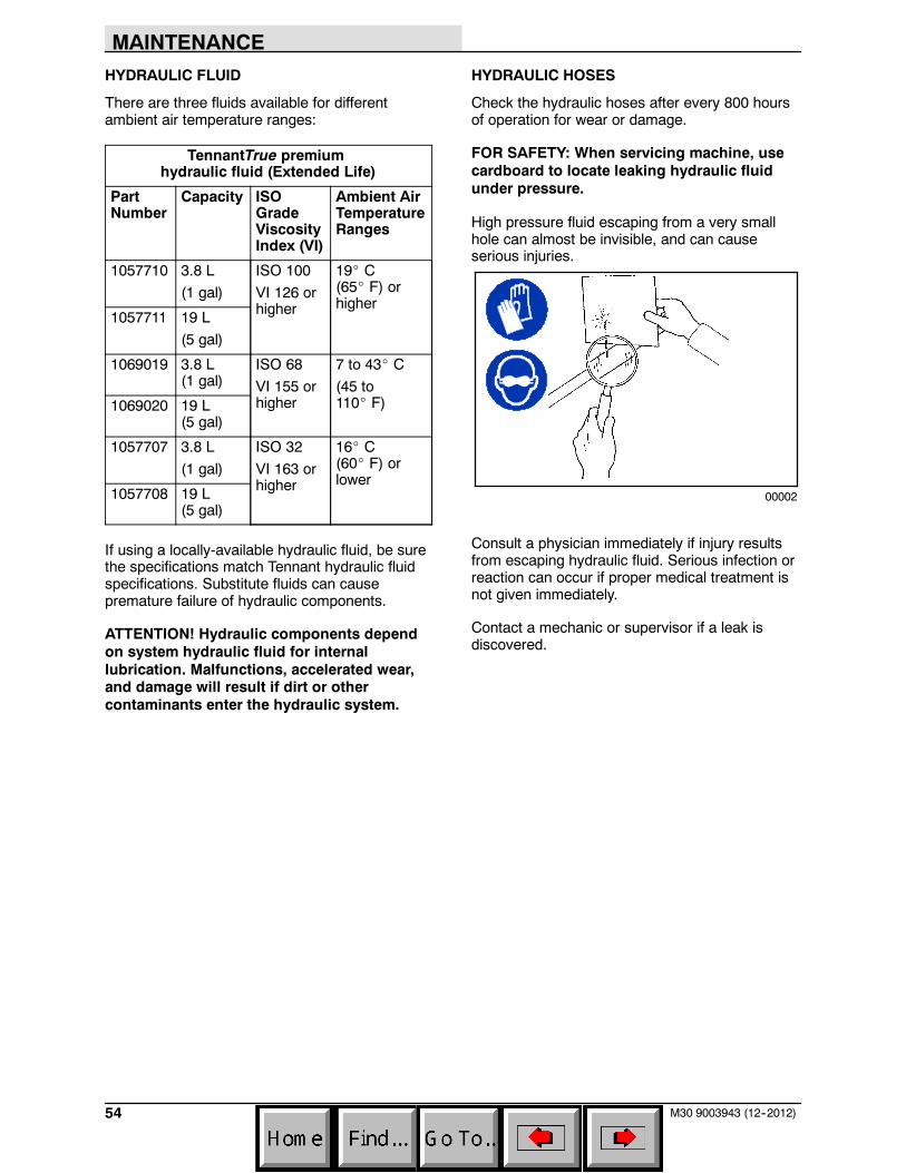
MAINTENANCE
54 M30 9003943 (12--2012)
HYDRAULIC FLUID
There are three fluids available for differentambient air temperature ranges:
TennantTrue premiumhydraulic fluid (Extended Life)
PartNumber
Capacity ISOGradeViscosityIndex (VI)
Ambient AirTemperatureRanges
1057710 3.8 L
(1 gal)
ISO 100
VI 126 orhigher
19_ C(65_ F) orhigher
1057711 19 L
(5 gal)
1069019 3.8 L(1 gal)
ISO 68
VI 155 orhigher
7 to 43_ C
(45 to110_ F)1069020 19 L
(5 gal)
1057707 3.8 L
(1 gal)
ISO 32
VI 163 orhigher
16_ C(60_ F) orlower
1057708 19 L(5 gal)
If using a locally-available hydraulic fluid, be surethe specifications match Tennant hydraulic fluidspecifications. Substitute fluids can causepremature failure of hydraulic components.
ATTENTION! Hydraulic components dependon system hydraulic fluid for internallubrication. Malfunctions, accelerated wear,and damage will result if dirt or othercontaminants enter the hydraulic system.
HYDRAULIC HOSES
Check the hydraulic hoses after every 800 hoursof operation for wear or damage.
FOR SAFETY: When servicing machine, usecardboard to locate leaking hydraulic fluidunder pressure.
High pressure fluid escaping from a very smallhole can almost be invisible, and can causeserious injuries.
00002
Consult a physician immediately if injury resultsfrom escaping hydraulic fluid. Serious infection orreaction can occur if proper medical treatment isnot given immediately.
Contact a mechanic or supervisor if a leak isdiscovered.
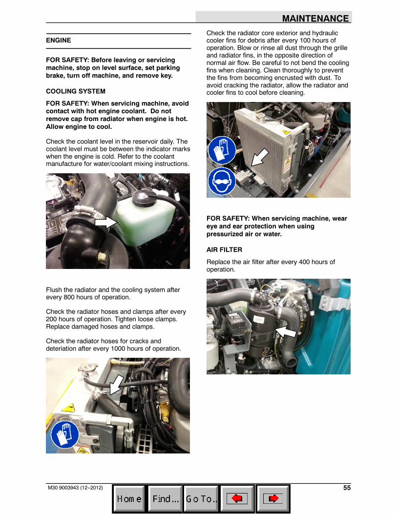
MAINTENANCE
55M30 9003943 (12--2012)
ENGINE
FOR SAFETY: Before leaving or servicingmachine, stop on level surface, set parkingbrake, turn off machine, and remove key.
COOLING SYSTEM
FOR SAFETY: When servicing machine, avoidcontact with hot engine coolant. Do notremove cap from radiator when engine is hot.Allow engine to cool.
Check the coolant level in the reservoir daily. Thecoolant level must be between the indicator markswhen the engine is cold. Refer to the coolantmanufacture for water/coolant mixing instructions.
Flush the radiator and the cooling system afterevery 800 hours of operation.
Check the radiator hoses and clamps after every200 hours of operation. Tighten loose clamps.Replace damaged hoses and clamps.
Check the radiator hoses for cracks anddeteriation after every 1000 hours of operation.
Check the radiator core exterior and hydrauliccooler fins for debris after every 100 hours ofoperation. Blow or rinse all dust through the grilleand radiator fins, in the opposite direction ofnormal air flow. Be careful to not bend the coolingfins when cleaning. Clean thoroughly to preventthe fins from becoming encrusted with dust. Toavoid cracking the radiator, allow the radiator andcooler fins to cool before cleaning.
FOR SAFETY: When servicing machine, weareye and ear protection when usingpressurized air or water.
AIR FILTER
Replace the air filter after every 400 hours ofoperation.
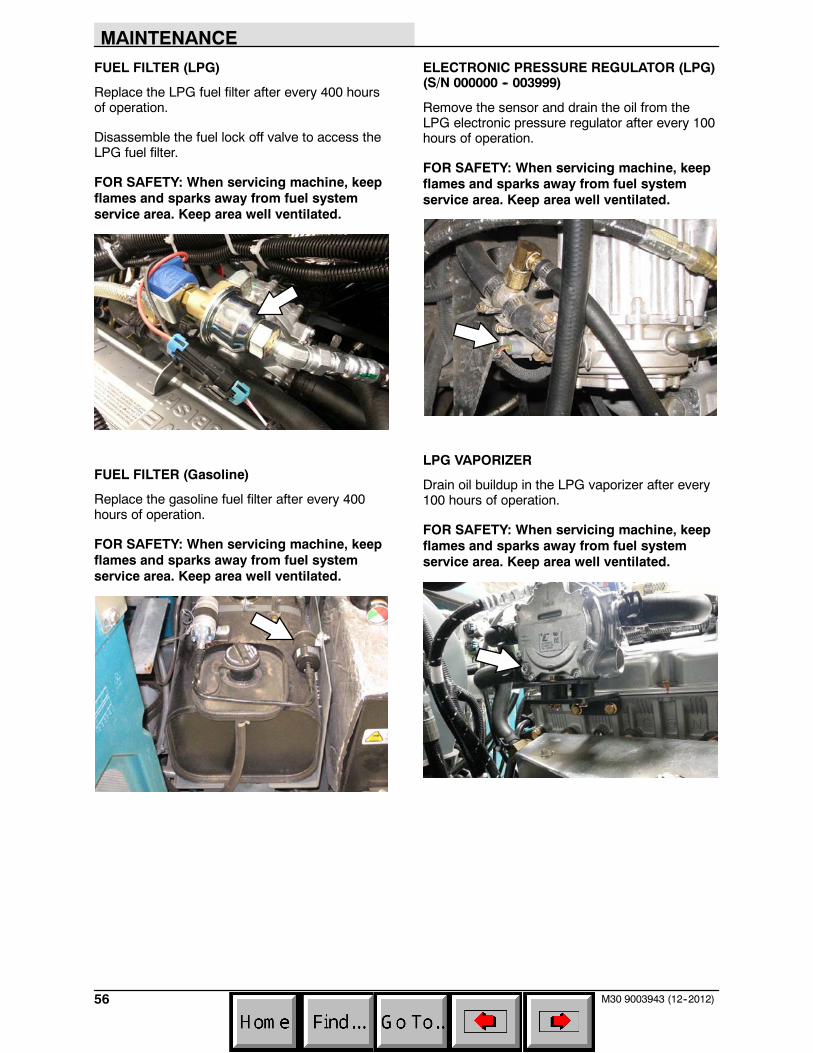
MAINTENANCE
56 M30 9003943 (12--2012)
FUEL FILTER (LPG)
Replace the LPG fuel filter after every 400 hoursof operation.
Disassemble the fuel lock off valve to access theLPG fuel filter.
FOR SAFETY: When servicing machine, keepflames and sparks away from fuel systemservice area. Keep area well ventilated.
FUEL FILTER (Gasoline)
Replace the gasoline fuel filter after every 400hours of operation.
FOR SAFETY: When servicing machine, keepflames and sparks away from fuel systemservice area. Keep area well ventilated.
ELECTRONIC PRESSURE REGULATOR (LPG)(S/N 000000 -- 003999)
Remove the sensor and drain the oil from theLPG electronic pressure regulator after every 100hours of operation.
FOR SAFETY: When servicing machine, keepflames and sparks away from fuel systemservice area. Keep area well ventilated.
LPG VAPORIZER
Drain oil buildup in the LPG vaporizer after every100 hours of operation.
FOR SAFETY: When servicing machine, keepflames and sparks away from fuel systemservice area. Keep area well ventilated.
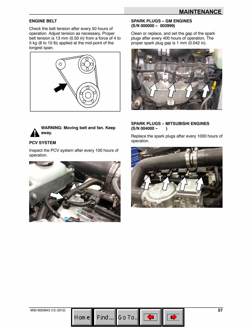
MAINTENANCE
57M30 9003943 (12--2012)
ENGINE BELT
Check the belt tension after every 50 hours ofoperation. Adjust tension as necessary. Properbelt tension is 13 mm (0.50 in) from a force of 4 to5 kg (8 to 10 lb) applied at the mid-point of thelongest span.
WARNING: Moving belt and fan. Keepaway.
PCV SYSTEM
Inspect the PCV system after every 100 hours ofoperation.
SPARK PLUGS -- GM ENGINES(S/N 000000 -- 003999)
Clean or replace, and set the gap of the sparkplugs after every 400 hours of operation. Theproper spark plug gap is 1 mm (0.042 in).
SPARK PLUGS -- MITSUBISHI ENGINES(S/N 004000 -- )
Replace the spark plugs after every 1000 hours ofoperation.
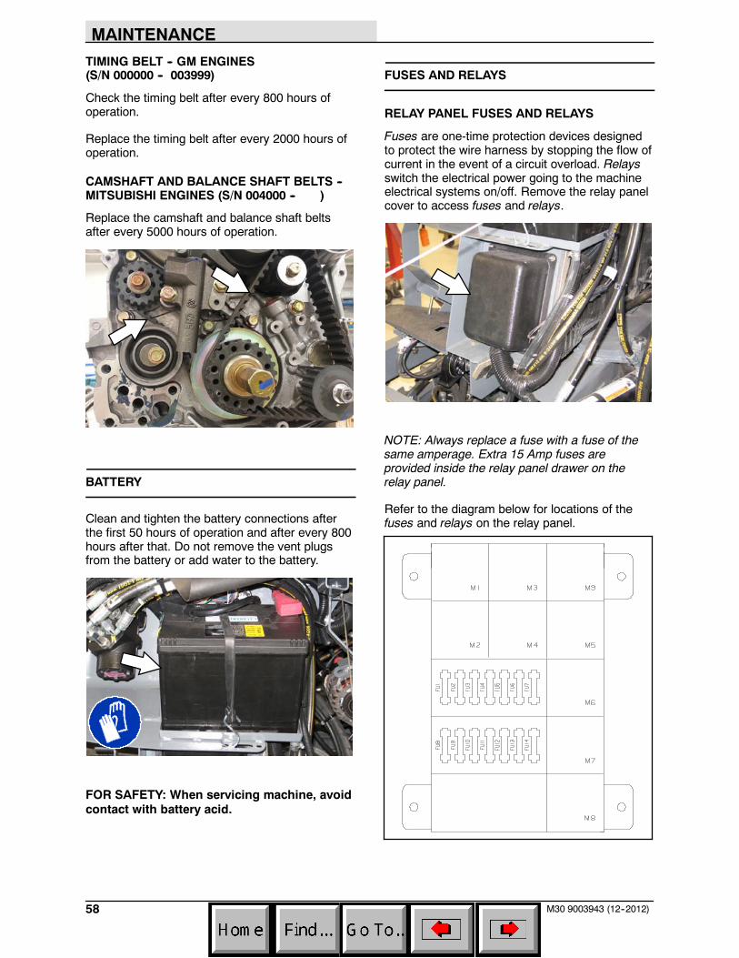
MAINTENANCE
58 M30 9003943 (12--2012)
TIMING BELT -- GM ENGINES(S/N 000000 -- 003999)
Check the timing belt after every 800 hours ofoperation.
Replace the timing belt after every 2000 hours ofoperation.
CAMSHAFT AND BALANCE SHAFT BELTS --MITSUBISHI ENGINES (S/N 004000 -- )
Replace the camshaft and balance shaft beltsafter every 5000 hours of operation.
BATTERY
Clean and tighten the battery connections afterthe first 50 hours of operation and after every 800hours after that. Do not remove the vent plugsfrom the battery or add water to the battery.
FOR SAFETY: When servicing machine, avoidcontact with battery acid.
FUSES AND RELAYS
RELAY PANEL FUSES AND RELAYS
Fuses are one-time protection devices designedto protect the wire harness by stopping the flow ofcurrent in the event of a circuit overload. Relaysswitch the electrical power going to the machineelectrical systems on/off. Remove the relay panelcover to access fuses and relays.
NOTE: Always replace a fuse with a fuse of thesame amperage. Extra 15 Amp fuses areprovided inside the relay panel drawer on therelay panel.
Refer to the diagram below for locations of thefuses and relays on the relay panel.
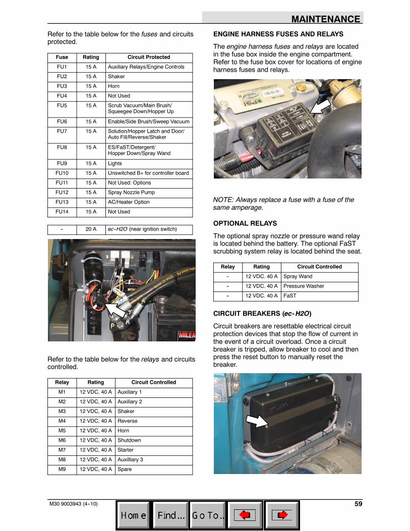
MAINTENANCE
59M30 9003943 (4--10)
Refer to the table below for the fuses and circuitsprotected.
Fuse Rating Circuit Protected
FU1 15 A Auxiliary Relays/Engine Controls
FU2 15 A Shaker
FU3 15 A Horn
FU4 15 A Not Used
FU5 15 A Scrub Vacuum/Main Brush/Squeegee Down/Hopper Up
FU6 15 A Enable/Side Brush/Sweep Vacuum
FU7 15 A Solution/Hopper Latch and Door/Auto Fill/Reverse/Shaker
FU8 15 A ES/FaST/Detergent/Hopper Down/Spray Wand
FU9 15 A Lights
FU10 15 A Unswitched B+ for controller board
FU11 15 A Not Used: Options
FU12 15 A Spray Nozzle Pump
FU13 15 A AC/Heater Option
FU14 15 A Not Used
-- 20 A ec--H2O (near ignition switch)
Refer to the table below for the relays and circuitscontrolled.
Relay Rating Circuit Controlled
M1 12 VDC, 40 A Auxiliary 1
M2 12 VDC, 40 A Auxiliary 2
M3 12 VDC, 40 A Shaker
M4 12 VDC, 40 A Reverse
M5 12 VDC, 40 A Horn
M6 12 VDC, 40 A Shutdown
M7 12 VDC, 40 A Starter
M8 12 VDC, 40 A Auxilliary 3
M9 12 VDC, 40 A Spare
ENGINE HARNESS FUSES AND RELAYS
The engine harness fuses and relays are locatedin the fuse box inside the engine compartment.Refer to the fuse box cover for locations of engineharness fuses and relays.
NOTE: Always replace a fuse with a fuse of thesame amperage.
OPTIONAL RELAYS
The optional spray nozzle or pressure wand relayis located behind the battery. The optional FaSTscrubbing system relay is located behind the seat.
Relay Rating Circuit Controlled
-- 12 VDC. 40 A Spray Wand
-- 12 VDC. 40 A Pressure Washer
-- 12 VDC. 40 A FaST
CIRCUIT BREAKERS (ec-H2O)
Circuit breakers are resettable electrical circuitprotection devices that stop the flow of current inthe event of a circuit overload. Once a circuitbreaker is tripped, allow breaker to cool and thenpress the reset button to manually reset thebreaker.
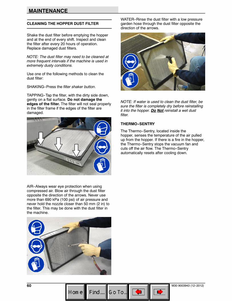
MAINTENANCE
60 M30 9003943 (12--2012)
CLEANING THE HOPPER DUST FILTER
Shake the dust filter before emptying the hopperand at the end of every shift. Inspect and cleanthe filter after every 20 hours of operation.Replace damaged dust filters.
NOTE: The dust filter may need to be cleaned atmore frequent intervals if the machine is used inextremely dusty conditions.
Use one of the following methods to clean thedust filter:
SHAKING--Press the filter shaker button.
TAPPING--Tap the filter, with the dirty side down,gently on a flat surface. Do not damage theedges of the filter. The filter will not seal properlyin the filter frame if the edges of the filter aredamaged.
AIR--Always wear eye protection when usingcompressed air. Blow air through the dust filteropposite the direction of the arrows. Never usemore than 690 kPa (100 psi) of air pressure andnever hold the nozzle closer than 50 mm (2 in) tothe filter. This may be done with the dust filter inthe machine.
WATER--Rinse the dust filter with a low pressuregarden hose through the dust filter opposite thedirection of the arrows.
NOTE: If water is used to clean the dust filter, besure the filter is completely dry before reinstallingit into the hopper. Do Not reinstall a wet dustfilter.
THERMO--SENTRY
The Thermo--Sentry, located inside thehopper, senses the temperature of the air pulledup from the hopper. If there is a fire in the hopper,the Thermo--Sentry stops the vacuum fan andcuts off the air flow. The Thermo--Sentryautomatically resets after cooling down.
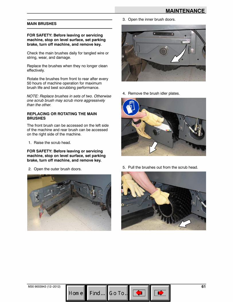
MAINTENANCE
61M30 9003943 (12--2012)
MAIN BRUSHES
FOR SAFETY: Before leaving or servicingmachine, stop on level surface, set parkingbrake, turn off machine, and remove key.
Check the main brushes daily for tangled wire orstring, wear, and damage.
Replace the brushes when they no longer cleaneffectively.
Rotate the brushes from front to rear after every50 hours of machine operation for maximumbrush life and best scrubbing performance.
NOTE: Replace brushes in sets of two. Otherwiseone scrub brush may scrub more aggressivelythan the other.
REPLACING OR ROTATING THE MAINBRUSHES
The front brush can be accessed on the left sideof the machine and rear brush can be accessedon the right side of the machine.
1. Raise the scrub head.
FOR SAFETY: Before leaving or servicingmachine, stop on level surface, set parkingbrake, turn off machine, and remove key.
2. Open the outer brush doors.
3. Open the inner brush doors.
4. Remove the brush idler plates.
5. Pull the brushes out from the scrub head.
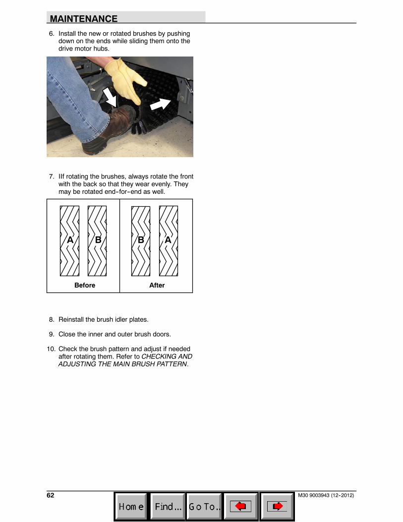
MAINTENANCE
62 M30 9003943 (12--2012)
6. Install the new or rotated brushes by pushingdown on the ends while sliding them onto thedrive motor hubs.
7. IIf rotating the brushes, always rotate the frontwith the back so that they wear evenly. Theymay be rotated end--for--end as well.
Before After
A B B A
8. Reinstall the brush idler plates.
9. Close the inner and outer brush doors.
10. Check the brush pattern and adjust if neededafter rotating them. Refer to CHECKING ANDADJUSTING THE MAIN BRUSH PATTERN.
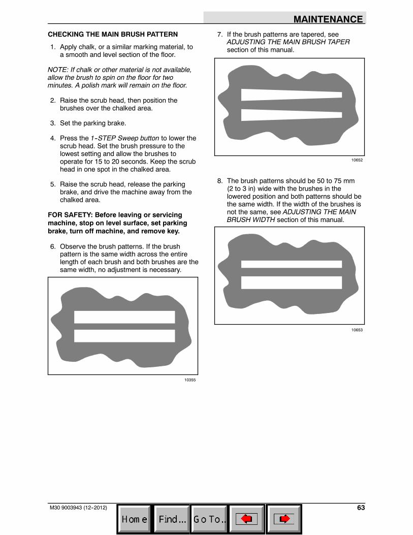
MAINTENANCE
63M30 9003943 (12--2012)
CHECKING THE MAIN BRUSH PATTERN
1. Apply chalk, or a similar marking material, toa smooth and level section of the floor.
NOTE: If chalk or other material is not available,allow the brush to spin on the floor for twominutes. A polish mark will remain on the floor.
2. Raise the scrub head, then position thebrushes over the chalked area.
3. Set the parking brake.
4. Press the 1--STEP Sweep button to lower thescrub head. Set the brush pressure to thelowest setting and allow the brushes tooperate for 15 to 20 seconds. Keep the scrubhead in one spot in the chalked area.
5. Raise the scrub head, release the parkingbrake, and drive the machine away from thechalked area.
FOR SAFETY: Before leaving or servicingmachine, stop on level surface, set parkingbrake, turn off machine, and remove key.
6. Observe the brush patterns. If the brushpattern is the same width across the entirelength of each brush and both brushes are thesame width, no adjustment is necessary.
10355
7. If the brush patterns are tapered, seeADJUSTING THE MAIN BRUSH TAPERsection of this manual.
10652
8. The brush patterns should be 50 to 75 mm(2 to 3 in) wide with the brushes in thelowered position and both patterns should bethe same width. If the width of the brushes isnot the same, see ADJUSTING THE MAINBRUSH WIDTH section of this manual.
10653
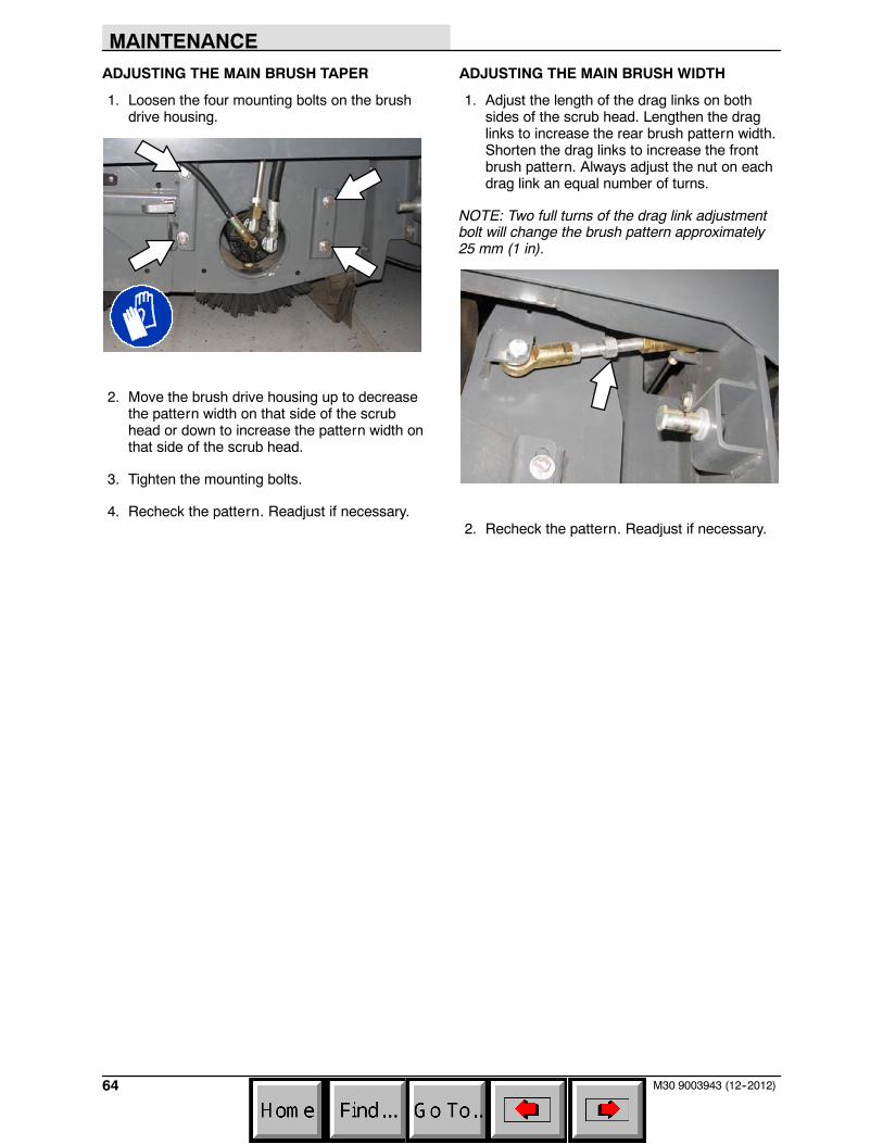
MAINTENANCE
64 M30 9003943 (12--2012)
ADJUSTING THE MAIN BRUSH TAPER
1. Loosen the four mounting bolts on the brushdrive housing.
2. Move the brush drive housing up to decreasethe pattern width on that side of the scrubhead or down to increase the pattern width onthat side of the scrub head.
3. Tighten the mounting bolts.
4. Recheck the pattern. Readjust if necessary.
ADJUSTING THE MAIN BRUSH WIDTH
1. Adjust the length of the drag links on bothsides of the scrub head. Lengthen the draglinks to increase the rear brush pattern width.Shorten the drag links to increase the frontbrush pattern. Always adjust the nut on eachdrag link an equal number of turns.
NOTE: Two full turns of the drag link adjustmentbolt will change the brush pattern approximately25 mm (1 in).
2. Recheck the pattern. Readjust if necessary.
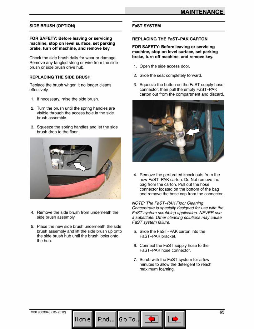
MAINTENANCE
65M30 9003943 (12--2012)
SIDE BRUSH (OPTION)
FOR SAFETY: Before leaving or servicingmachine, stop on level surface, set parkingbrake, turn off machine, and remove key.
Check the side brush daily for wear or damage.Remove any tangled string or wire from the sidebrush or side brush drive hub.
REPLACING THE SIDE BRUSH
Replace the brush whgen it no longer cleanseffectively.
1. If necessary, raise the side brush.
2. Turn the brush until the spring handles arevisible through the access hole in the sidebrush assembly.
3. Squeeze the spring handles and let the sidebrush drop to the floor.
4. Remove the side brush from underneath theside brush assembly.
5. Place the new side brush underneath the sidebrush assembly and lift the side brush up ontothe side brush hub until the brush locks ontothe hub.
FaST SYSTEM
REPLACING THE FaST--PAK CARTON
FOR SAFETY: Before leaving or servicingmachine, stop on level surface, set parkingbrake, turn off machine, and remove key.
1. Open the side access door.
2. Slide the seat completely forward.
3. Squeeze the button on the FaST supply hoseconnector, then pull the empty FaST--PAKcarton out from the compartment and discard.
4. Remove the perforated knock outs from thenew FaST--PAK carton. Do Not remove thebag from the carton. Pull out the hoseconnector located on the bottom of the bagand remove the hose cap from the connector.
NOTE: The FaST--PAK Floor CleaningConcentrate is specially designed for use with theFaST system scrubbing application. NEVER usea substitute. Other cleaning solutions may causeFaST system failure.
5. Slide the FaST--PAK carton into theFaST--PAK bracket.
6. Connect the FaST supply hose to theFaST--PAK hose connector.
7. Scrub with the FaST system for a fewminutes to allow the detergent to reachmaximum foaming.
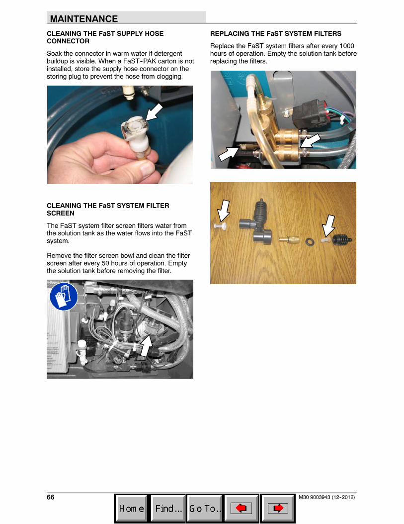
MAINTENANCE
66 M30 9003943 (12--2012)
CLEANING THE FaST SUPPLY HOSECONNECTOR
Soak the connector in warm water if detergentbuildup is visible. When a FaST--PAK carton is notinstalled, store the supply hose connector on thestoring plug to prevent the hose from clogging.
CLEANING THE FaST SYSTEM FILTERSCREEN
The FaST system filter screen filters water fromthe solution tank as the water flows into the FaSTsystem.
Remove the filter screen bowl and clean the filterscreen after every 50 hours of operation. Emptythe solution tank before removing the filter.
REPLACING THE FaST SYSTEM FILTERS
Replace the FaST system filters after every 1000hours of operation. Empty the solution tank beforereplacing the filters.
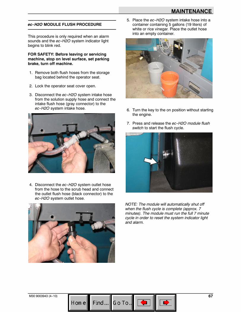
MAINTENANCE
67M30 9003943 (4--10)
ec-H2O MODULE FLUSH PROCEDURE
This procedure is only required when an alarmsounds and the ec--H2O system indicator lightbegins to blink red.
FOR SAFETY: Before leaving or servicingmachine, stop on level surface, set parkingbrake, turn off machine.
1. Remove both flush hoses from the storagebag located behind the operator seat.
2. Lock the operator seat cover open.
3. Disconnect the ec--H2O system intake hosefrom the solution supply hose and connect theintake flush hose (gray connector) to theec--H2O system intake hose.
4. Disconnect the ec--H2O system outlet hosefrom the hose to the scrub head and connectthe outlet flush hose (black connector) to theec--H2O system outlet hose.
5. Place the ec--H2O system intake hose into acontainer containing 5 gallons (19 liters) ofwhite or rice vinegar. Place the outlet hoseinto an empty container.
6. Turn the key to the on position without startingthe engine.
7. Press and release the ec--H2O module flushswitch to start the flush cycle.
NOTE: The module will automatically shut offwhen the flush cycle is complete (approx. 7minutes). The module must run the full 7 minutecycle in order to reset the system indicator lightand alarm.
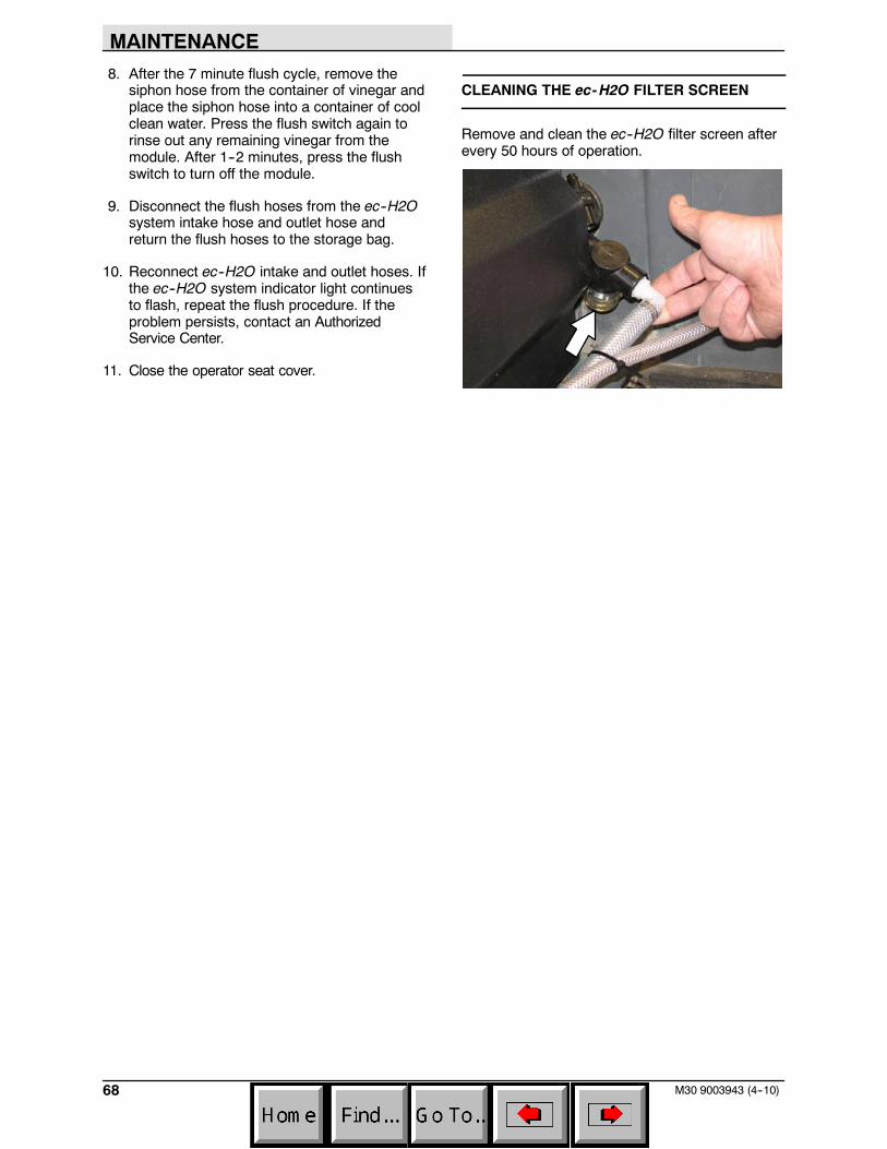
MAINTENANCE
68 M30 9003943 (4--10)
8. After the 7 minute flush cycle, remove thesiphon hose from the container of vinegar andplace the siphon hose into a container of coolclean water. Press the flush switch again torinse out any remaining vinegar from themodule. After 1--2 minutes, press the flushswitch to turn off the module.
9. Disconnect the flush hoses from the ec--H2Osystem intake hose and outlet hose andreturn the flush hoses to the storage bag.
10. Reconnect ec--H2O intake and outlet hoses. Ifthe ec--H2O system indicator light continuesto flash, repeat the flush procedure. If theproblem persists, contact an AuthorizedService Center.
11. Close the operator seat cover.
CLEANING THE ec-H2O FILTER SCREEN
Remove and clean the ec--H2O filter screen afterevery 50 hours of operation.
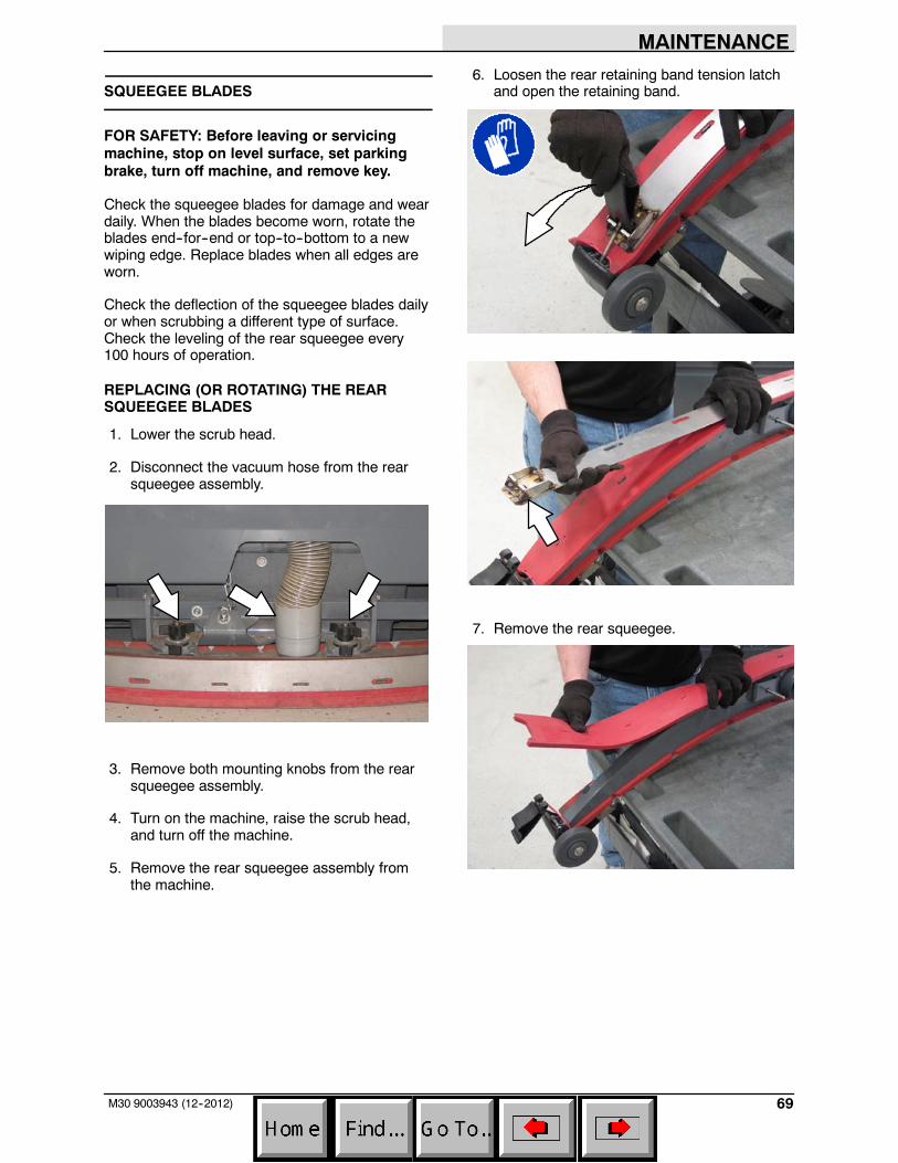
MAINTENANCE
69M30 9003943 (12--2012)
SQUEEGEE BLADES
FOR SAFETY: Before leaving or servicingmachine, stop on level surface, set parkingbrake, turn off machine, and remove key.
Check the squeegee blades for damage and weardaily. When the blades become worn, rotate theblades end--for--end or top--to--bottom to a newwiping edge. Replace blades when all edges areworn.
Check the deflection of the squeegee blades dailyor when scrubbing a different type of surface.Check the leveling of the rear squeegee every100 hours of operation.
REPLACING (OR ROTATING) THE REARSQUEEGEE BLADES
1. Lower the scrub head.
2. Disconnect the vacuum hose from the rearsqueegee assembly.
3. Remove both mounting knobs from the rearsqueegee assembly.
4. Turn on the machine, raise the scrub head,and turn off the machine.
5. Remove the rear squeegee assembly fromthe machine.
6. Loosen the rear retaining band tension latchand open the retaining band.
7. Remove the rear squeegee.
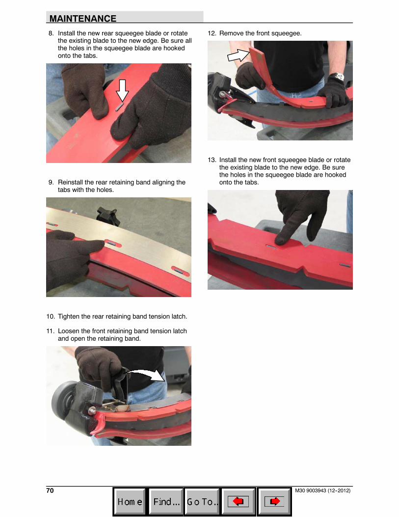
MAINTENANCE
70 M30 9003943 (12--2012)
8. Install the new rear squeegee blade or rotatethe existing blade to the new edge. Be sure allthe holes in the squeegee blade are hookedonto the tabs.
9. Reinstall the rear retaining band aligning thetabs with the holes.
10. Tighten the rear retaining band tension latch.
11. Loosen the front retaining band tension latchand open the retaining band.
12. Remove the front squeegee.
13. Install the new front squeegee blade or rotatethe existing blade to the new edge. Be surethe holes in the squeegee blade are hookedonto the tabs.
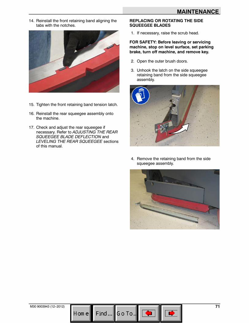
MAINTENANCE
71M30 9003943 (12--2012)
14. Reinstall the front retaining band aligning thetabs with the notches.
15. Tighten the front retaining band tension latch.
16. Reinstall the rear squeegee assembly ontothe machine.
17. Check and adjust the rear squeegee ifnecessary. Refer to ADJUSTING THE REARSQUEEGEE BLADE DEFLECTION andLEVELING THE REAR SQUEEGEE sectionsof this manual.
REPLACING OR ROTATING THE SIDESQUEEGEE BLADES
1. If necessary, raise the scrub head.
FOR SAFETY: Before leaving or servicingmachine, stop on level surface, set parkingbrake, turn off machine, and remove key.
2. Open the outer brush doors.
3. Unhook the latch on the side squeegeeretaining band from the side squeegeeassembly.
4. Remove the retaining band from the sidesqueegee assembly.
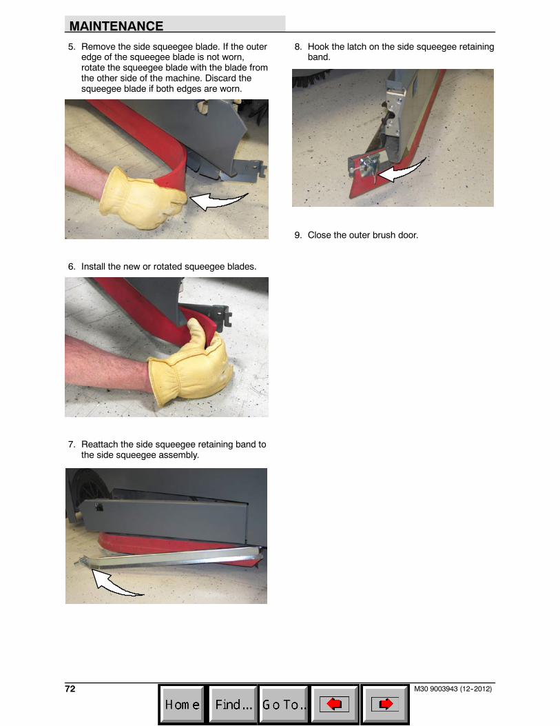
MAINTENANCE
72 M30 9003943 (12--2012)
5. Remove the side squeegee blade. If the outeredge of the squeegee blade is not worn,rotate the squeegee blade with the blade fromthe other side of the machine. Discard thesqueegee blade if both edges are worn.
6. Install the new or rotated squeegee blades.
7. Reattach the side squeegee retaining band tothe side squeegee assembly.
8. Hook the latch on the side squeegee retainingband.
9. Close the outer brush door.
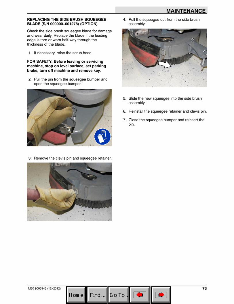
MAINTENANCE
73M30 9003943 (12--2012)
REPLACING THE SIDE BRUSH SQUEEGEEBLADE (S/N 000000--001278) (OPTION)
Check the side brush squeegee blade for damageand wear daily. Replace the blade if the leadingedge is torn or worn half-way through thethickness of the blade.
1. If necessary, raise the scrub head.
FOR SAFETY: Before leaving or servicingmachine, stop on level surface, set parkingbrake, turn off machine and remove key.
2. Pull the pin from the squeegee bumper andopen the squeegee bumper.
3. Remove the clevis pin and squeegee retainer.
4. Pull the squeegee out from the side brushassembly.
5. Slide the new squeegee into the side brushassembly.
6. Reinstall the squeegee retainer and clevis pin.
7. Close the squeegee bumper and reinsert thepin.
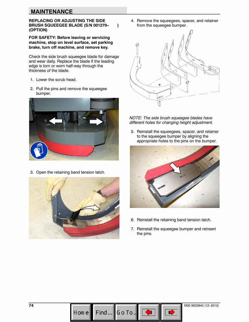
MAINTENANCE
74 M30 9003943 (12--2012)
REPLACING OR ADJUSTING THE SIDEBRUSH SQUEEGEE BLADE (S/N 001279-- )(OPTION)
FOR SAFETY: Before leaving or servicingmachine, stop on level surface, set parkingbrake, turn off machine, and remove key.
Check the side brush squeegee blade for damageand wear daily. Replace the blade if the leadingedge is torn or worn half-way through thethickness of the blade.
1. Lower the scrub head.
2. Pull the pins and remove the squeegeebumper.
3. Open the retaining band tension latch.
4. Remove the squeegees, spacer, and retainerfrom the squeegee bumper.
NOTE: The side brush squeegee blades havedifferent holes for changing height adjustment.
5. Reinstall the squeegees, spacer, and retainerto the squeegee bumper by aligning theappropriate holes to the pins on the bumper.
6. Reinstall the retaining band tension latch.
7. Reinstall the squeegee bumper and reinsertthe pins.
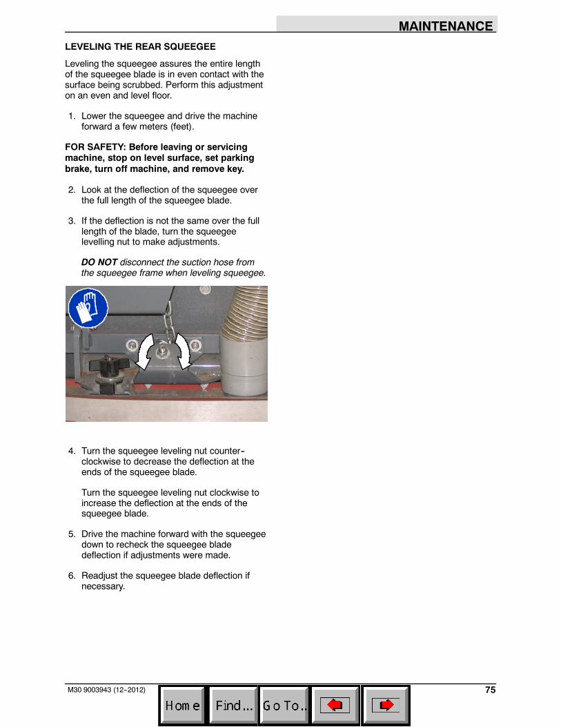
MAINTENANCE
75M30 9003943 (12--2012)
LEVELING THE REAR SQUEEGEE
Leveling the squeegee assures the entire lengthof the squeegee blade is in even contact with thesurface being scrubbed. Perform this adjustmenton an even and level floor.
1. Lower the squeegee and drive the machineforward a few meters (feet).
FOR SAFETY: Before leaving or servicingmachine, stop on level surface, set parkingbrake, turn off machine, and remove key.
2. Look at the deflection of the squeegee overthe full length of the squeegee blade.
3. If the deflection is not the same over the fulllength of the blade, turn the squeegeelevelling nut to make adjustments.
DO NOT disconnect the suction hose fromthe squeegee frame when leveling squeegee.
4. Turn the squeegee leveling nut counter--clockwise to decrease the deflection at theends of the squeegee blade.
Turn the squeegee leveling nut clockwise toincrease the deflection at the ends of thesqueegee blade.
5. Drive the machine forward with the squeegeedown to recheck the squeegee bladedeflection if adjustments were made.
6. Readjust the squeegee blade deflection ifnecessary.
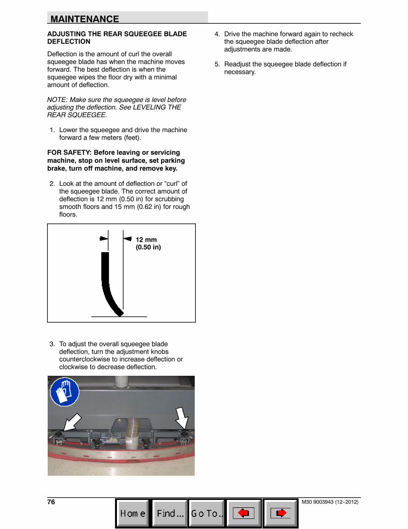
MAINTENANCE
76 M30 9003943 (12--2012)
ADJUSTING THE REAR SQUEEGEE BLADEDEFLECTION
Deflection is the amount of curl the overallsqueegee blade has when the machine movesforward. The best deflection is when thesqueegee wipes the floor dry with a minimalamount of deflection.
NOTE: Make sure the squeegee is level beforeadjusting the deflection. See LEVELING THEREAR SQUEEGEE.
1. Lower the squeegee and drive the machineforward a few meters (feet).
FOR SAFETY: Before leaving or servicingmachine, stop on level surface, set parkingbrake, turn off machine, and remove key.
2. Look at the amount of deflection or “curl” ofthe squeegee blade. The correct amount ofdeflection is 12 mm (0.50 in) for scrubbingsmooth floors and 15 mm (0.62 in) for roughfloors.
12 mm(0.50 in)
3. To adjust the overall squeegee bladedeflection, turn the adjustment knobscounterclockwise to increase deflection orclockwise to decrease deflection.
4. Drive the machine forward again to recheckthe squeegee blade deflection afteradjustments are made.
5. Readjust the squeegee blade deflection ifnecessary.
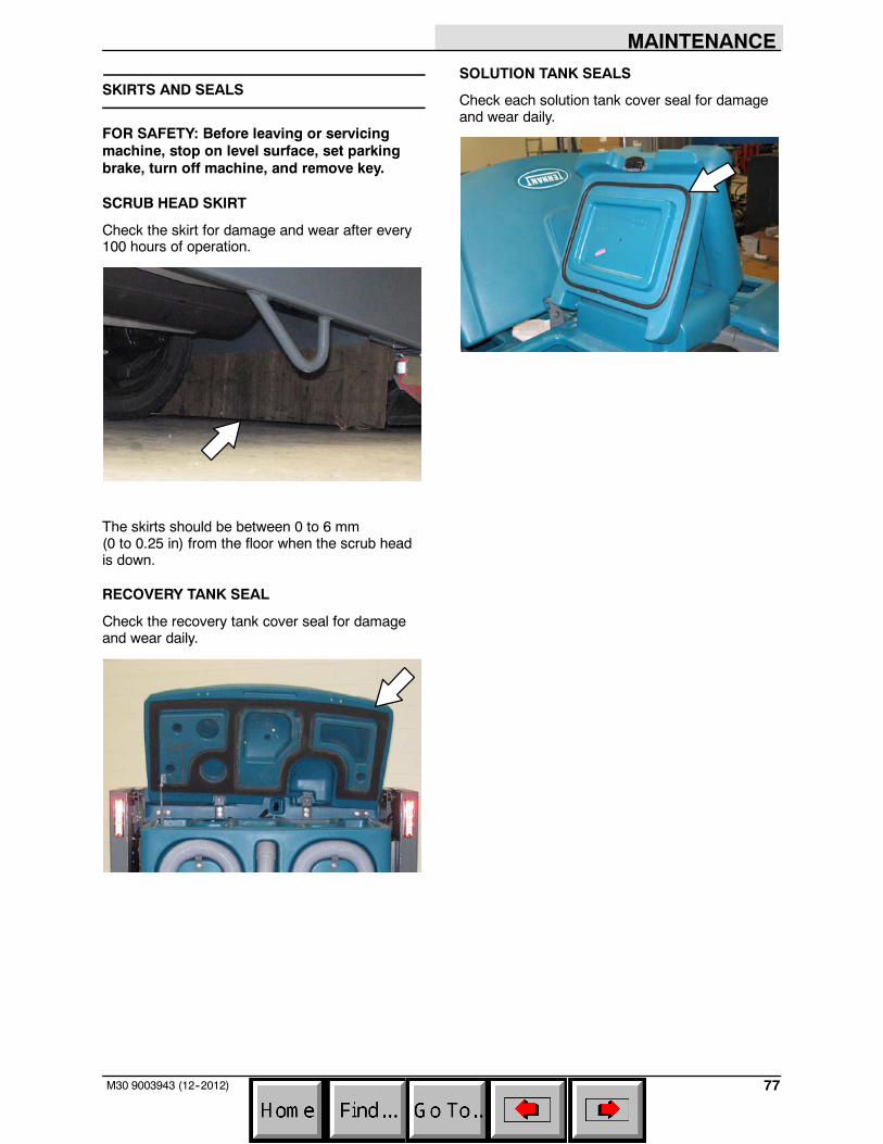
MAINTENANCE
77M30 9003943 (12--2012)
SKIRTS AND SEALS
FOR SAFETY: Before leaving or servicingmachine, stop on level surface, set parkingbrake, turn off machine, and remove key.
SCRUB HEAD SKIRT
Check the skirt for damage and wear after every100 hours of operation.
The skirts should be between 0 to 6 mm(0 to 0.25 in) from the floor when the scrub headis down.
RECOVERY TANK SEAL
Check the recovery tank cover seal for damageand wear daily.
SOLUTION TANK SEALS
Check each solution tank cover seal for damageand wear daily.
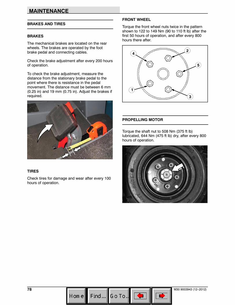
MAINTENANCE
78 M30 9003943 (12--2012)
BRAKES AND TIRES
BRAKES
The mechanical brakes are located on the rearwheels. The brakes are operated by the footbrake pedal and connecting cables.
Check the brake adjustment after every 200 hoursof operation.
To check the brake adjustment, measure thedistance from the stationary brake pedal to thepoint where there is resistance in the pedalmovement. The distance must be between 6 mm(0.25 in) and 19 mm (0.75 in). Adjust the brakes ifrequired.
TIRES
Check tires for damage and wear after every 100hours of operation.
FRONT WHEEL
Torque the front wheel nuts twice in the patternshown to 122 to 149 Nm (90 to 110 ft lb) after thefirst 50 hours of operation, and after every 800hours there after.
2
3
4
1
5
PROPELLING MOTOR
Torque the shaft nut to 508 Nm (375 ft lb)lubricated, 644 Nm (475 ft lb) dry, after every 800hours of operation.
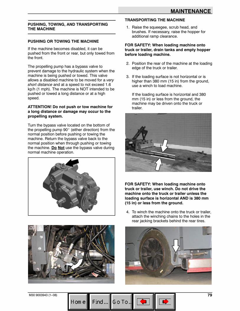
MAINTENANCE
79M30 9003943 (1--08)
PUSHING, TOWING, AND TRANSPORTINGTHE MACHINE
PUSHING OR TOWING THE MACHINE
If the machine becomes disabled, it can bepushed from the front or rear, but only towed fromthe front.
The propelling pump has a bypass valve toprevent damage to the hydraulic system when themachine is being pushed or towed. This valveallows a disabled machine to be moved for a veryshort distance and at a speed to not exceed 1.6kp/h (1 mph). The machine is NOT intended to bepushed or towed a long distance or at a highspeed.
ATTENTION! Do not push or tow machine fora long distance or damage may occur to thepropelling system.
Turn the bypass valve located on the bottom ofthe propelling pump 90_ (either direction) from thenormal position before pushing or towing themachine. Return the bypass valve back to thenormal position when through pushing or towingthe machine. Do Not use the bypass valve duringnormal machine operation.
TRANSPORTING THE MACHINE
1. Raise the squeegee, scrub head, andbrushes. If necessary, raise the hopper foradditional ramp clearance.
FOR SAFETY: When loading machine ontotruck or trailer, drain tanks and empty hopperbefore loading machine.
2. Position the rear of the machine at the loadingedge of the truck or trailer.
3. If the loading surface is not horizontal or ishigher than 380 mm (15 in) from the ground,use a winch to load machine.
If the loading surface is horizontal and 380mm (15 in) or less from the ground, themachine may be driven onto the truck ortrailer.
FOR SAFETY: When loading machine ontotruck or trailer, use winch. Do not drive themachine onto the truck or trailer unless theloading surface is horizontal AND is 380 mm(15 in) or less from the ground.
4. To winch the machine onto the truck or trailer,attach the winching chains to the holes in therear jacking brackets behind the rear tires.
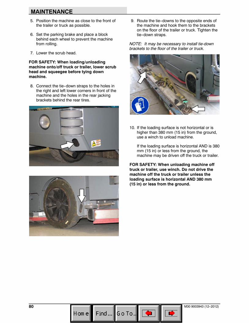
MAINTENANCE
80 M30 9003943 (12--2012)
5. Position the machine as close to the front ofthe trailer or truck as possible.
6. Set the parking brake and place a blockbehind each wheel to prevent the machinefrom rolling.
7. Lower the scrub head.
FOR SAFETY: When loading/unloadingmachine onto/off truck or trailer, lower scrubhead and squeegee before tying downmachine.
8. Connect the tie--down straps to the holes inthe right and left lower corners in front of themachine and the holes in the rear jackingbrackets behind the rear tires.
9. Route the tie--downs to the opposite ends ofthe machine and hook them to the bracketson the floor of the trailer or truck. Tighten thetie--down straps.
NOTE: It may be necessary to install tie-downbrackets to the floor of the trailer or truck.
10. If the loading surface is not horizontal or ishigher than 380 mm (15 in) from the ground,use a winch to unload machine.
If the loading surface is horizontal AND is 380mm (15 in) or less from the ground, themachine may be driven off the truck or trailer.
FOR SAFETY: When unloading machine offtruck or trailer, use winch. Do not drive themachine off the truck or trailer unless theloading surface is horizontal AND 380 mm(15 in) or less from the ground.
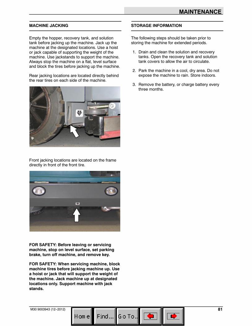
MAINTENANCE
81M30 9003943 (12--2012)
MACHINE JACKING
Empty the hopper, recovery tank, and solutiontank before jacking up the machine. Jack up themachine at the designated locations. Use a hoistor jack capable of supporting the weight of themachine. Use jackstands to support the machine.Always stop the machine on a flat, level surfaceand block the tires before jacking up the machine.
Rear jacking locations are located directly behindthe rear tires on each side of the machine.
Front jacking locations are located on the framedirectly in front of the front tire.
FOR SAFETY: Before leaving or servicingmachine, stop on level surface, set parkingbrake, turn off machine, and remove key.
FOR SAFETY: When servicing machine, blockmachine tires before jacking machine up. Usea hoist or jack that will support the weight ofthe machine. Jack machine up at designatedlocations only. Support machine with jackstands.
STORAGE INFORMATION
The following steps should be taken prior tostoring the machine for extended periods.
1. Drain and clean the solution and recoverytanks. Open the recovery tank and solutiontank covers to allow the air to circulate.
2. Park the machine in a cool, dry area. Do notexpose the machine to rain. Store indoors.
3. Remove the battery, or charge battery everythree months.
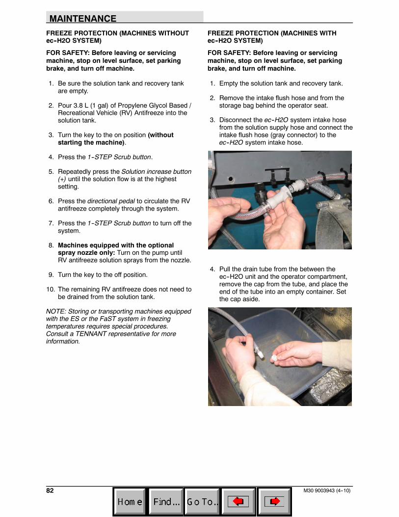
MAINTENANCE
82 M30 9003943 (4--10)
FREEZE PROTECTION (MACHINES WITHOUTec--H2O SYSTEM)
FOR SAFETY: Before leaving or servicingmachine, stop on level surface, set parkingbrake, and turn off machine.
1. Be sure the solution tank and recovery tankare empty.
2. Pour 3.8 L (1 gal) of Propylene Glycol Based /Recreational Vehicle (RV) Antifreeze into thesolution tank.
3. Turn the key to the on position (withoutstarting the machine).
4. Press the 1--STEP Scrub button.
5. Repeatedly press the Solution increase button(+) until the solution flow is at the highestsetting.
6. Press the directional pedal to circulate the RVantifreeze completely through the system.
7. Press the 1--STEP Scrub button to turn off thesystem.
8. Machines equipped with the optionalspray nozzle only: Turn on the pump untilRV antifreeze solution sprays from the nozzle.
9. Turn the key to the off position.
10. The remaining RV antifreeze does not need tobe drained from the solution tank.
NOTE: Storing or transporting machines equippedwith the ES or the FaST system in freezingtemperatures requires special procedures.Consult a TENNANT representative for moreinformation.
FREEZE PROTECTION (MACHINES WITHec--H2O SYSTEM)
FOR SAFETY: Before leaving or servicingmachine, stop on level surface, set parkingbrake, and turn off machine.
1. Empty the solution tank and recovery tank.
2. Remove the intake flush hose and from thestorage bag behind the operator seat.
3. Disconnect the ec--H2O system intake hosefrom the solution supply hose and connect theintake flush hose (gray connector) to theec--H2O system intake hose.
4. Pull the drain tube from the between theec--H2O unit and the operator compartment,remove the cap from the tube, and place theend of the tube into an empty container. Setthe cap aside.
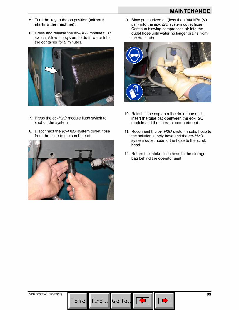
MAINTENANCE
83M30 9003943 (12--2012)
5. Turn the key to the on position (withoutstarting the machine).
6. Press and release the ec--H2O module flushswitch. Allow the system to drain water intothe container for 2 minutes.
7. Press the ec--H2O module flush switch toshut off the system.
8. Disconnect the ec--H2O system outlet hosefrom the hose to the scrub head.
9. Blow pressurized air (less than 344 kPa (50psi)) into the ec--H2O system outlet hose.Continue blowing compressed air into theoutlet hose until water no longer drains fromthe drain tube
10. Reinstall the cap onto the drain tube andinsert the tube back between the ec--H2Omodule and the operator compartment.
11. Reconnect the ec--H2O system intake hose tothe solution supply hose and the ec--H2Osystem outlet hose to the hose to the scrubhead.
12. Return the intake flush hose to the storagebag behind the operator seat.
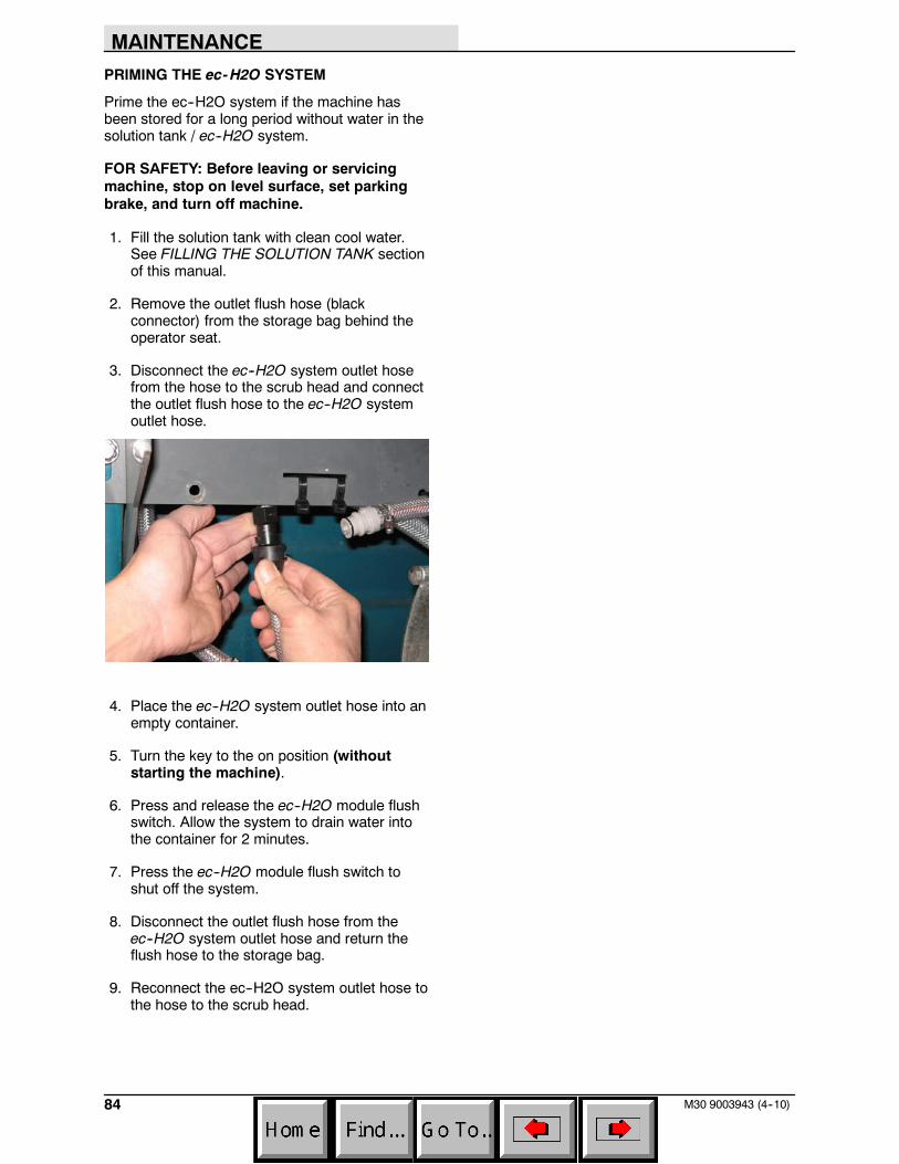
MAINTENANCE
84 M30 9003943 (4--10)
PRIMING THE ec-H2O SYSTEM
Prime the ec--H2O system if the machine hasbeen stored for a long period without water in thesolution tank / ec--H2O system.
FOR SAFETY: Before leaving or servicingmachine, stop on level surface, set parkingbrake, and turn off machine.
1. Fill the solution tank with clean cool water.See FILLING THE SOLUTION TANK sectionof this manual.
2. Remove the outlet flush hose (blackconnector) from the storage bag behind theoperator seat.
3. Disconnect the ec--H2O system outlet hosefrom the hose to the scrub head and connectthe outlet flush hose to the ec--H2O systemoutlet hose.
4. Place the ec--H2O system outlet hose into anempty container.
5. Turn the key to the on position (withoutstarting the machine).
6. Press and release the ec--H2O module flushswitch. Allow the system to drain water intothe container for 2 minutes.
7. Press the ec--H2O module flush switch toshut off the system.
8. Disconnect the outlet flush hose from theec--H2O system outlet hose and return theflush hose to the storage bag.
9. Reconnect the ec--H2O system outlet hose tothe hose to the scrub head.
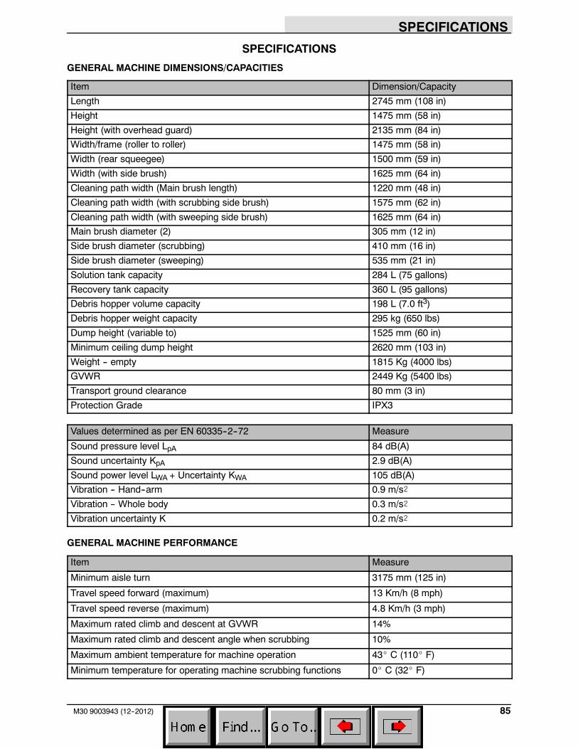
SPECIFICATIONS
85M30 9003943 (12--2012)
SPECIFICATIONS
GENERAL MACHINE DIMENSIONS/CAPACITIES
Item Dimension/Capacity
Length 2745 mm (108 in)
Height 1475 mm (58 in)
Height (with overhead guard) 2135 mm (84 in)
Width/frame (roller to roller) 1475 mm (58 in)
Width (rear squeegee) 1500 mm (59 in)
Width (with side brush) 1625 mm (64 in)
Cleaning path width (Main brush length) 1220 mm (48 in)
Cleaning path width (with scrubbing side brush) 1575 mm (62 in)
Cleaning path width (with sweeping side brush) 1625 mm (64 in)
Main brush diameter (2) 305 mm (12 in)
Side brush diameter (scrubbing) 410 mm (16 in)
Side brush diameter (sweeping) 535 mm (21 in)
Solution tank capacity 284 L (75 gallons)
Recovery tank capacity 360 L (95 gallons)
Debris hopper volume capacity 198 L (7.0 ft3)
Debris hopper weight capacity 295 kg (650 lbs)
Dump height (variable to) 1525 mm (60 in)
Minimum ceiling dump height 2620 mm (103 in)
Weight -- empty 1815 Kg (4000 lbs)
GVWR 2449 Kg (5400 lbs)
Transport ground clearance 80 mm (3 in)
Protection Grade IPX3
Values determined as per EN 60335--2--72 Measure
Sound pressure level LpA 84 dB(A)
Sound uncertainty KpA 2.9 dB(A)
Sound power level LWA + Uncertainty KWA 105 dB(A)
Vibration -- Hand--arm 0.9 m/s@
Vibration -- Whole body 0.3 m/s@
Vibration uncertainty K 0.2 m/s@
GENERAL MACHINE PERFORMANCE
Item Measure
Minimum aisle turn 3175 mm (125 in)
Travel speed forward (maximum) 13 Km/h (8 mph)
Travel speed reverse (maximum) 4.8 Km/h (3 mph)
Maximum rated climb and descent at GVWR 14%
Maximum rated climb and descent angle when scrubbing 10%
Maximum ambient temperature for machine operation 43_ C (110_ F)
Minimum temperature for operating machine scrubbing functions 0_ C (32_ F)
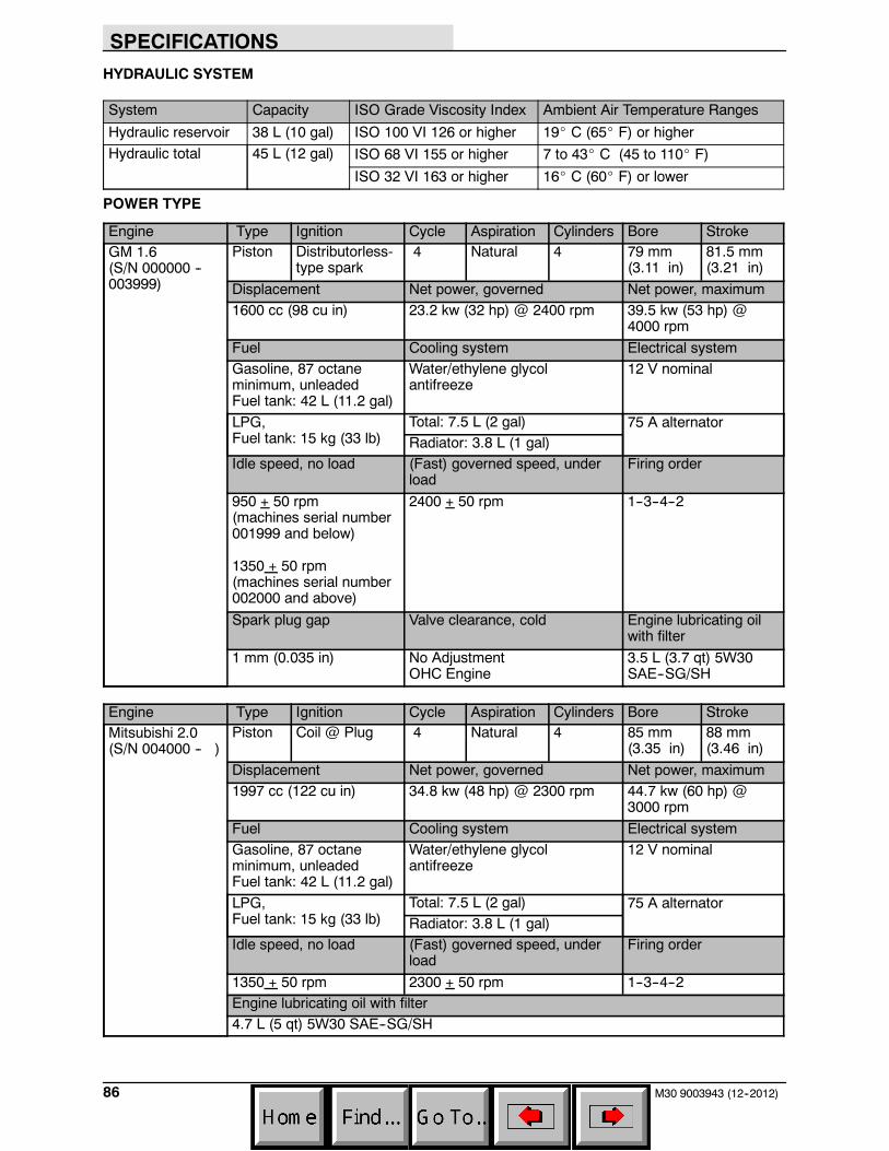
SPECIFICATIONS
86 M30 9003943 (12--2012)
HYDRAULIC SYSTEM
System Capacity ISO Grade Viscosity Index Ambient Air Temperature Ranges
Hydraulic reservoir 38 L (10 gal) ISO 100 VI 126 or higher 19_ C (65_ F) or higher
Hydraulic total 45 L (12 gal) ISO 68 VI 155 or higher 7 to 43_ C (45 to 110_ F)
ISO 32 VI 163 or higher 16_ C (60_ F) or lower
POWER TYPE
Engine Type Ignition Cycle Aspiration Cylinders Bore StrokeGM 1.6(S/N 000000 --003999)
Piston Distributorless-type spark
4 Natural 4 79 mm(3.11 in)
81.5 mm(3.21 in)
Displacement Net power, governed Net power, maximum1600 cc (98 cu in) 23.2 kw (32 hp) @ 2400 rpm 39.5 kw (53 hp) @
4000 rpm
Fuel Cooling system Electrical systemGasoline, 87 octaneminimum, unleadedFuel tank: 42 L (11.2 gal)
Water/ethylene glycolantifreeze
12 V nominal
LPG,Fuel tank: 15 kg (33 lb)
Total: 7.5 L (2 gal) 75 A alternatorRadiator: 3.8 L (1 gal)
Idle speed, no load (Fast) governed speed, underload
Firing order
950 + 50 rpm(machines serial number001999 and below)
1350 + 50 rpm(machines serial number002000 and above)
2400 + 50 rpm 1--3--4--2
Spark plug gap Valve clearance, cold Engine lubricating oilwith filter
1 mm (0.035 in) No AdjustmentOHC Engine
3.5 L (3.7 qt) 5W30SAE--SG/SH
Engine Type Ignition Cycle Aspiration Cylinders Bore StrokeMitsubishi 2.0(S/N 004000 -- )
Piston Coil @ Plug 4 Natural 4 85 mm(3.35 in)
88 mm(3.46 in)
Displacement Net power, governed Net power, maximum1997 cc (122 cu in) 34.8 kw (48 hp) @ 2300 rpm 44.7 kw (60 hp) @
3000 rpm
Fuel Cooling system Electrical systemGasoline, 87 octaneminimum, unleadedFuel tank: 42 L (11.2 gal)
Water/ethylene glycolantifreeze
12 V nominal
LPG,Fuel tank: 15 kg (33 lb)
Total: 7.5 L (2 gal) 75 A alternatorRadiator: 3.8 L (1 gal)
Idle speed, no load (Fast) governed speed, underload
Firing order
1350 + 50 rpm 2300 + 50 rpm 1--3--4--2Engine lubricating oil with filter4.7 L (5 qt) 5W30 SAE--SG/SH
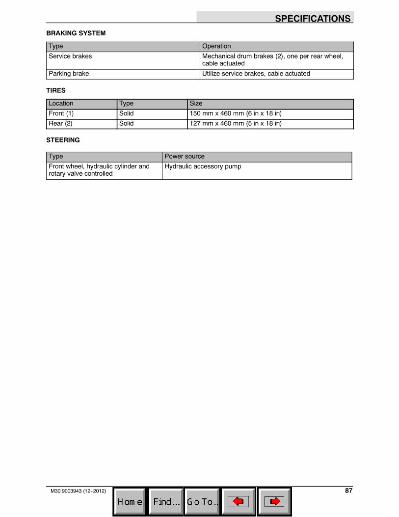
SPECIFICATIONS
87M30 9003943 (12--2012)
BRAKING SYSTEM
Type Operation
Service brakes Mechanical drum brakes (2), one per rear wheel,cable actuated
Parking brake Utilize service brakes, cable actuated
TIRES
Location Type Size
Front (1) Solid 150 mm x 460 mm (6 in x 18 in)
Rear (2) Solid 127 mm x 460 mm (5 in x 18 in)
STEERING
Type Power source
Front wheel, hydraulic cylinder androtary valve controlled
Hydraulic accessory pump
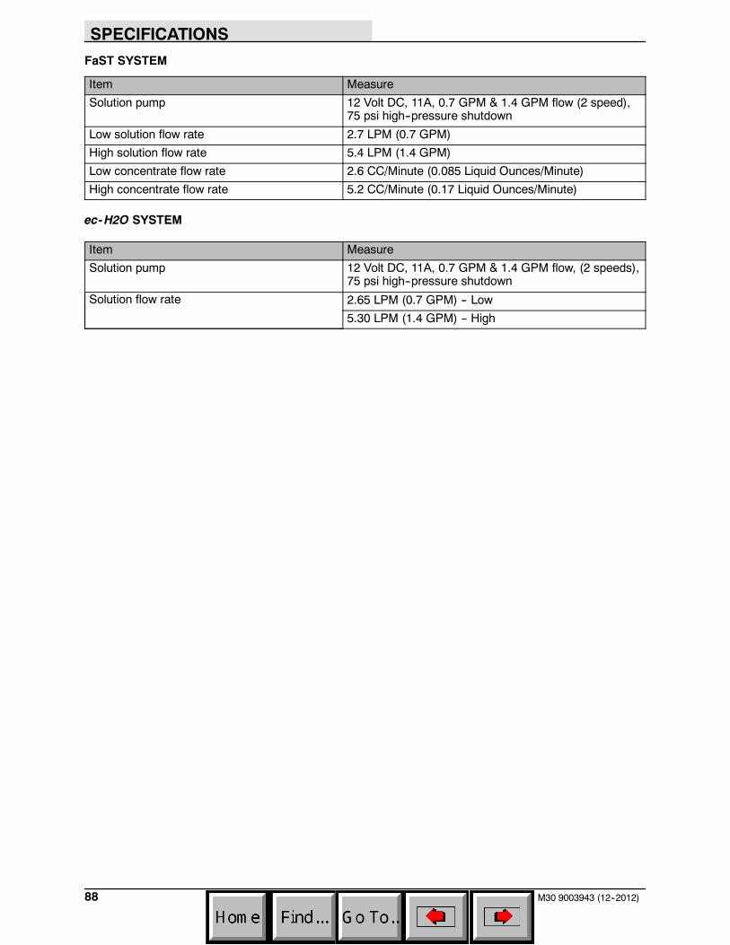
SPECIFICATIONS
88 M30 9003943 (12--2012)
FaST SYSTEM
Item Measure
Solution pump 12 Volt DC, 11A, 0.7 GPM & 1.4 GPM flow (2 speed),75 psi high--pressure shutdown
Low solution flow rate 2.7 LPM (0.7 GPM)
High solution flow rate 5.4 LPM (1.4 GPM)
Low concentrate flow rate 2.6 CC/Minute (0.085 Liquid Ounces/Minute)
High concentrate flow rate 5.2 CC/Minute (0.17 Liquid Ounces/Minute)
ec-H2O SYSTEM
Item Measure
Solution pump 12 Volt DC, 11A, 0.7 GPM & 1.4 GPM flow, (2 speeds),75 psi high--pressure shutdown
Solution flow rate 2.65 LPM (0.7 GPM) -- Low
5.30 LPM (1.4 GPM) -- High
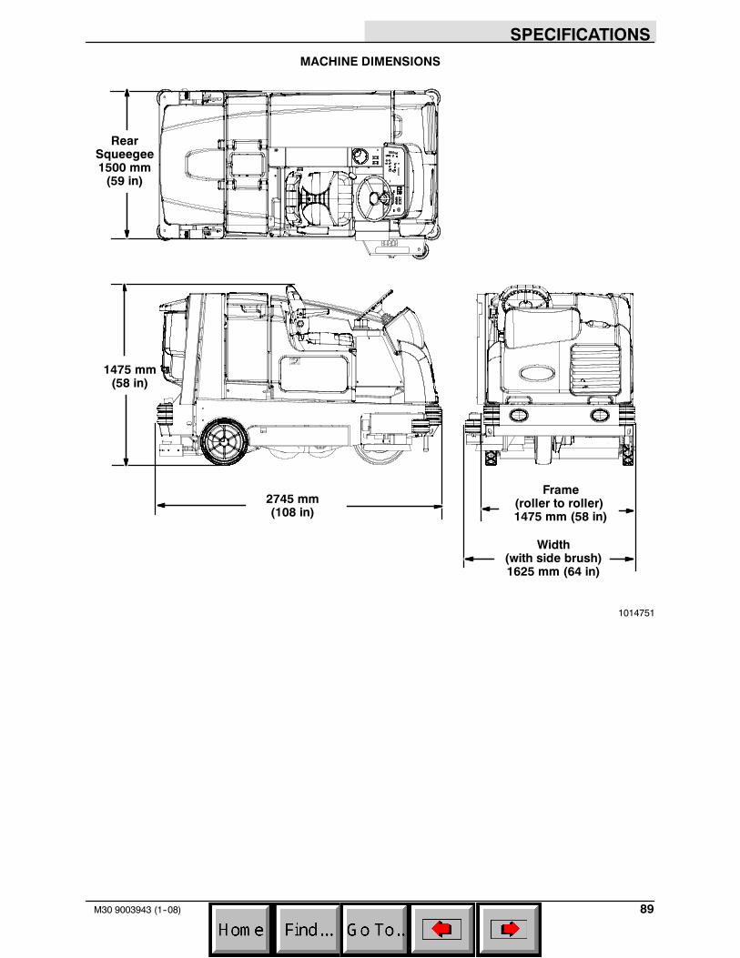
SPECIFICATIONS
89M30 9003943 (1--08)
MACHINE DIMENSIONS
Frame(roller to roller)1475 mm (58 in)
1475 mm(58 in)
2745 mm(108 in)
RearSqueegee1500 mm(59 in)
Width(with side brush)1625 mm (64 in)
1014751
INDEX
90 M30 9003943 (12--2012)
Numbers
1---STEP Scrub button, 12, 16, 23, 24, 25, 26, 27
1---STEP Sweep button, 12, 16, 24, 28
A
Adjust operator seat, 14
Adjust steering column, 15
Adjusting the Main Brush Taper, 64
Adjusting the Main Brush Width, 64
Adjusting the Rear Squeegee Blade Deflection,76
Air Filter, 55
Alarms, 39Fault Indicators, 39
B
Battery, 58
Belts, Camshaft and Balance, 58
Brake pedal, 15
Brakes, 78System specifications, 87
Brakes and Tires, 78Brakes, 78Front Wheel, 78Tires, 78
Brush Information, 17
Buttons1--STEP Scrub button, 251--STEP Sweep button, 28Brush Pressure decrease button (--), 24Brush Pressure increase button (+), 24ec--H20 button, 23Engine Speed Button, 12ES (Extended Scrub) button, 23FaST button, 23Filter shaker button, 29Hopper door open/close button, 29Hopper raise/lower button, 29Scrub vacuum fan/squeegee button, 26Side Brush button (Option), 12Solution decrease button (--), 24Solution increase button (+), 24Supervisor Control Buttons, 13Sweep vacuum fan button, 28
Buttons, Controls and Instruments, 9, 12
Bypass valve, 79
C
Camshaft and Balance Shaft Belts, 58
Capacities, 85
Changing the LPG Tank, 19
Charging System Indicator, 11
Check Engine Indicator, 11
Checking the Main Brush Pattern, 63
Cleaning the ec---H20 fitler screen, 68
Cleaning the FaST Supply Hose Connector, 66
Cleaning the FaST System Check Valves, 66
Cleaning the FaST System Filter Screen, 66
Cleaning the Hopper and Debris Screen, 32
Cleaning the Hopper Dust Filter, 60
Conditions / Warnings, 40
Controls and Instruments, 8, 9Touch Panel, 9
Cooling System, 55
D
Dimensions, 85
Directional pedal, 15
Disengaging Hopper Support Pin, 30
Double Scrubbing, 26
Draining and Cleaning the Recovery Tank, 34Draining the Recovery Tank with the Drain
Hose, 34Draining the Recovery Tank with the Drain Plug,
35
Draining and Cleaning the Solution Tank, 37
Draining the Recovery Tank with the Drain Hose,34
Draining the Recovery Tank with the Drain Plug,35
Dust Filter, 31Removing the Hopper Dust Filter, 31Replacing the Hopper Dust Filter, 31
INDEX
91M30 9003943 (12--2012)
E
ec---H20 module flush switch, 67
ec---H20 Scrubbing System, Indicator LightCodes, 25
ec---H20 Scrubbing System Indicator LightCodes , 25
ec---H2O system indicator light, 25
Electronic Pressure Regulator, 56
Emptying the Hopper, 29
Engaging Hopper Support Pin, 30
Engine, 55Air Filter, 55Camshaft and Balance Shaft Belts, 58Cooling System, 55Electronic Pressure Regulator, 56Engine Belt, 57Fuel Filter, 56LPG Vaporizer, 56PCV System, 57Spark Plugs, 57Specifications, 86Timing Belt, 58
Engine Belt, 57
Engine Harness Fuses and Relays, 59
Engine Oil, 51
Engine Oil Pressure Indicator, 11
Engine Speed Button, 12
F
FaST System, 65, 67Cleaning the FaST Supply Hose Connector, 66Cleaning the FaST System Check Valves, 66Cleaning the FaST System Filter Screen, 66Replacing the FaST--PAK Carton, 65
Fault Indicators, 39
Filling the Solution Tank, 21Conventional Scrubbing Mode, 21ec--H20 scrubbing (ec--H20 Mode), 21ES (Extended Scrub) Mode -- Manually Filling
Tanks, 22ES (Extended Scrub) Mode with Auto--Fill, 22Foam scrubbing (FaST Mode), 21
Filters, 31Cleaning the Hopper Dust Filter, 60Engine Air Filter, 55Gasoline Fuel Filter, 56Hydraulic Fluid Filter, 53LPG Fuel Filter, 56Removing the Hopper Dust Filter, 31Replacing the Hopper Dust Filter, 31
Freeze Protection (Machines with ec---H20system), 82
Freeze Protection (Machines without ec---H20system), 82
Front Wheel Support Bearing, 51
Front Wheel, Torque, 78
Fuel FilterGasoline, 56LPG, 56
Fuel Indicator, 12
Fuses and Relays, 58Engine Harness Fuses and Relays, 59Optional, 59Relay Panel Fuses and Relays, 58, 59
H
Hazard Light Switch (Option), 13
Headlights, 13
High Presure Washer (Option), 43
Hopper Door Pivots, 52
Hopper Lift Arm Pivots, 52
Hopper Support Pin, 30Disengaging Hopper Support Pin, 30Engaging Hopper Support Pin, 30
Hour Meter, 13
How the Machine Works, 16
Hydraulic Fluid, 54
Hydraulic Hoses, 54
Hydraulic System, System specifications, 86
Hydraulics, 53Drain and refill hydraulic fluid reservoir, 53Hydraulic Fluid, 54Hydraulic Hoses, 54Replace the filler cap, 53Replace the hydraulic fluid filter, 53
INDEX
92 M30 9003943 (12--2012)
I
Incline, Rated, 17
Indicator light, ec---H2O system, 25
Indicator Light Codes, ec---H20 ScrubbingSystem, 25
IndicatorsCharging System Indicator, 11Check Engine Indicator, 11Conditions / Warnings, 40Engine Oil Pressure Indicator, 11Fault Indicators, 39Fuel Indicator, 12Hour Meter, 13
L
Leveling the Rear Squeegee, 75
LightsHazard Light Switch (Option), 13Headlights, 13Operating, 13
LPG Vaporizer, 56
Lubrication, 51Engine Oil, 51Front Wheel Support Bearing, 51Hopper Door Pivots, 52Hopper Lift Arm Pivots, 52Squeegee Caster Bearings, 51Steering Cylinder Bearing, 51Torque Tubes, 52
M
Machine components, 7
Machine Dimensions, 89
Machine Jacking, 81
Machine Operation, Pre---Operation Checklist, 18
Machine PerformanceAisle Turnaround Width, 85Climb and Descent Angles, 85Travel Speed (Maximum), 85
Machine Specifications, 85 --- 88
Machine Troubleshooting, 45
Main Brushes, 61Adjusting the Taper, 64Adjusting the Width, 64Checking the Main Brush Pattern, 63Replacing or Rotating the Main Brushes, 61
Main Brushes, Adjusting the Taper, 64
Main Brushes, Adjusting the Width, 64
Main Brushes, Checking the Pattern, 63
Main Brushes, Replacing or Rotating, 61
Maintenance, 47 --- 71
Maintenance Chart, 48
O
Operating Lights, 13
Operating temperature, 17
Operation, 7 --- 31
Operation of controls, 11
Operator seat, 14
Optional Relays, 59
Options, 41Hazard Light, 13High Presure Washer, 43Side Brush, 12Spray Nozzle, 41Squeegee protectors, 15Vacuum Wand, 42
INDEX
93M30 9003943 (12--2012)
P
Parking brake pedal, 15
PCV System, 57
PedalsBrake pedal, 15Directional pedal, 15Parking brake pedal, 15
Pre---Operation Checklist, 18
Priming the ec---H20 system, 84
Propelling Motor, 78Torque Shaft Nut, 78
Pushing or Towing the Machine, 79
Pushing, Towing, and Transporting the Machine,79
Pushing or Towing the Machine, 79Transporting the Machine, 79
R
Radiator, 55Check hoses and clamps, 55Clean core exterior, 55
Rated incline, 17
Rear SqueegeeAdjusting the Rear Squeegee Blade Deflection,
76Leveling the Rear Squeegee, 75
Rear Squeegee Blade, Replacing (or Rotating)the Rear Squeegee Blade, 69
Rear Squeegee, Replacing (or Rotating), 69
Recovery Tank Seal, 77
Relay Panel Fuses and Relays, 58, 59
Removing the Hopper Dust Filter, 31
Replacing (or Rotating) the Rear SqueegeeBlades, 69
Replacing or Adjusting the Side Brush SqueegeeBlade (S/N 003077--- ) (Option), 74
Replacing or Rotating the Main Brushes, 61
Replacing or Rotating the Side SqueegeeBlades, 71
Replacing the FaST---PAK Carton, 65
Replacing the Hopper Dust Filter, 31
Replacing the Side Brush (Option), 65
Replacing the Side Brush Squeegee Blade (S/N000000---003076) (Option), 73
S
SafetyInstructions, 3 -- 5Labels, 5 -- 7
Scrub Head Skirt, 77
Scrubbing, 25
Seals, 77Recovery Tank Seal, 77Solution Tank Seals, 77
Seat belts, 14
Seat, Operator, 14
Setting Brush Pressure, 24
Setting Conventional Solution Flow, 24
Setting ec---H20 Mode, 23
Setting ES (Extended Scrub) Mode, 23
Setting ES Solution Flow, 24
Setting FaST Mode, 23
Setting FaST Solution Flow, 24
Setting Scrub Modes, 23Setting Brush Pressure, 24Setting ec--H20 Mode, 23Setting ES (Extended Scrub) Mode, 23Setting ES Solution Flow, 24Setting FaST Mode, 23Setting Solution Flow, 24Conventional and FaST Mode, 24ES (Extended Scrub) Mode, 24
Setting the Engine Speed, 12
Side Brush, 12
Side Brush (Option), 65Replacing the Side Brush, 65Replacing the Side Brush Squeegee (S/N
000000--003076), 73
Side Brush (S/N 003077--- ) (Option),Replacing the Side Brush Squeegee, 74
Side Brush Squeegee (S/N 000000---003076)(Option), Replacing, 73
Side Brush Squeegee (S/N 003077--- )(Option), Replacing or Adjusting, 74
Side Brush, Replacing, 65
Side Squeegee Blades, 71Replacing or Rotating the Side Squeegee
Blades, 71
Side Squeegee, Replacing or Rotating, 71
INDEX
94 M30 9003943 (12--2012)
Skirts and Seals, 77Recovery Tank Seal, 77Scrub Head Skirt, 77Solution Tank Seals, 77
Solution Tank Seals, 77
Spark Plugs, 57
Specifications, 85 --- 88Braking system, 87ec--H20 System, 88FaST System, 88Hydraulic System, 86Machine Capacities, 85Machine Dimensions, 85Machine Performance, 85Power Type, 86Steering, 87Tires, 87
Spray Nozzle (Option), 41
Squeegee Blades, 69Replacing (or Rotating) the Rear Squeegee
Blades, 69Replacing or Rotating the Side Squeegee
Blades, 71
Squeegee Caster Bearings, 51
Squeegee Protectors (Option), 15
Starting the Machine, 20
Steering, Specifications, 87
Steering Cylinder Bearing, 51
Storage Information, 81Freeze Protection, 82Priming the ec--H20 system, 84Storing the Machine, 81
Supervisor Control Buttons, 13
Sweeping, 27
Symbol definitions, 10 --- 12
T
Temperature, Operating, 17
Thermo---Sentry, 60
Timing Belt, 58
Tires, 78Specifications, 87
Torque Tubes, 52
Touch Panel, 9
Towing the Machine, 79
Transporting the Machine, 79
Turning Off the Machine, 20
V
Vacuum Wand (Option), 42
Vaporizer, 56
W
Warning Indicators, 11, 39Charging System Indicator, 11Check Engine Indicator, 11Conditions / Warnings, 40Engine Oil Pressure Indicator, 11Fault Indicators, 39
Water Pickup Mode (No Scrubbing), 27
Wheels, 78
While Operating the Machine, 17