Embed Size (px)
Citation preview
550
*330650*
Rider ScrubberOperator Manual
330650Rev. 11 (12-2013)
North America / International
(Gas/LPG)
(S/N 006115− )
TennantTrue� Parts
For the latest Parts manuals and otherlanguage Operator manuals, visit:
www.tennantco.com/manuals
This manual is furnished with each new model. It provides necessary operation and maintenance instructions.
Read this manual completely and understand the machine before operating or servicing it.
This machine will provide excellent service. However, the best results will be obtained at minimum costs if:
� The machine is operated with reasonable care.
� The machine is maintained regularly - per the machine maintenance instructions provided.
� The machine is maintained with manufacturer supplied or equivalent parts.
PROTECT THE ENVIRONMENTPlease dispose of packaging materials,old machine components such asbatteries, hazardous fluids includingantifreeze and oil, in an environmentallysafe way according to local wastedisposal regulations.
Always remember to recycle.
MACHINE DATA
Please fill out at time of installation for future reference.
Model No. −
Serial No. −
Machine Options −
Sales Rep. −
Sales Rep. phone no. −
Customer Number −
Installation Date −
Tennant CompanyPO Box 1452Minneapolis, MN 55440Phone: (800) 553−8033 or (763) 513−2850www.tennantco.com
CALIFORNIA PROPOSITION 65 WARNING: Engine exhaust from this product contains chemicals known to the State of California to cause cancer,birth defects, or other reproductive harm.
SRS is a US registered trademark of Tennant Company.
Specifications and parts are subject to change without notice.
Original instructions, Copyright � 1999−2002, 2004, 2006−2008, 2010, 2011, 2013 TENNANT Company, Printed in U.S.A.
CONTENTS
1550 Gas/LPG 330650 (3−11)
CONTENTS
PageSAFETY PRECAUTIONS 5. . . . . . . . . . . . . . . . .OPERATION 9. . . . . . . . . . . . . . . . . . . . . . . . . . . . . .
PREPARATION FOR OPERATION 9. . . . . .AFTER UNLOADING AND BEFORE
OPERATING THE MACHINE: 9. . . . . . . .OPERATION OF CONTROLS 10. . . . . . . . . .
MACHINE COMPONENTS 10. . . . . . . . . .INSTRUMENTS AND CONTROLS
(For machines below serial number 007006) 11. . . . . . . . . . . . . .
INSTRUMENTS AND CONTROLS (For machines serial number
007006 and above) 12. . . . . . . . . . . .BRAKE PEDAL 13. . . . . . . . . . . . . . . . . . . .DIRECTIONAL PEDAL 13. . . . . . . . . . . . . .OPERATOR SEAT 13. . . . . . . . . . . . . . . . . .SCRUB HEAD LOCK LEVER 13. . . . . . . .SCRUB BRUSH LEVER 13. . . . . . . . . . . . .PIVOT LOCK PIN 14. . . . . . . . . . . . . . . . . .PARKING BRAKE LEVER 14. . . . . . . . . . .AMMETER (For machines below serial
number 007006) 14. . . . . . . . . . . . . . . . .CHARGING SYSTEM LIGHT (For
machines serial number 007006 and above) 14. . . . . . . . . . . . . . . . . . .
SQUEEGEE POSITION LAMP (For machines below serial
number 007006) 14. . . . . . . . . . . . . .CHECK ENGINE LIGHT (For machines
serial number 007006 and above) 14. .IGNITION SWITCH 14. . . . . . . . . . . . . . . . .ROTATING LIGHT SWITCH (OPTION) 15HAZARD LIGHT SWITCH (OPTION) 15. .FUEL LEVEL GAUGE 15. . . . . . . . . . . . . . .PANEL LAMP (OPTION) 15. . . . . . . . . . . .TANK DRAIN LAMP (OPTION) 15. . . . . . .SCRUB BRUSH PRESSURE LAMP
(OPTION) 15. . . . . . . . . . . . . . . . . . . . . .ENGINE HOUR METER 15. . . . . . . . . . . . .FUSES (For machines below serial
number 007006) 15. . . . . . . . . . . . . . . . .FUSES (For machines serial number
007006 and above) 15. . . . . . . . . . . . . .CIRCUIT BREAKERS (For machines
serial number 007006 and above) 16. .ENGINE OIL PRESSURE GAUGE −
CONTINENTAL ENGINES (For machines below serial number
006409) 16. . . . . . . . . . . . . . . . . .ENGINE OIL PRESSURE GAUGE −
GM ENGINES (For machines serial number 006409 − 007005) 16. . . . .
ENGINE OIL PRESSURE LIGHT (For machines serial number 007006
and above) 16. . . . . . . . . . . . . . . . . . .
PageENGINE COOLANT TEMPERATURE
GAUGE 16. . . . . . . . . . . . . . . . . . . . . . . .SQUEEGEE SWITCH 16. . . . . . . . . . . . . . .SCRUB HEAD POSITION LEVER 17. . . .SRS LIQUID LOW LEVEL LAMPS
(OPTION) 17. . . . . . . . . . . . . . . . . . . . . .SRS CLEANING SOLUTION FLOW
KNOB (OPTION) 17. . . . . . . . . . . . . . . .SOLUTION LEVER 17. . . . . . . . . . . . . . . . .ENGINE CHOKE KNOB −
CONTINENTAL ENGINES 17. . . . . . . .THROTTLE LEVER − CONTINENTAL
ENGINES (For machines below serial number 006409) 17. . . . . . . . . . . . . .
THROTTLE SWITCH − GM ENGINES (For machines serial number 006409
and above) 17. . . . . . . . . . . . . . . . . . .STEERING WHEEL 17. . . . . . . . . . . . . . . .HORN BUTTON (For machines serial
number 007006 and above) 17. . . . . . .MACHINE OPERATION 18. . . . . . . . . . . . . . . .
NORMAL SCRUBBING OPERATION 18.PRE-START CHECKLIST 18. . . . . . . . . . .TO START MACHINE 18. . . . . . . . . . . . . . .TO FILL SOLUTION TANK 19. . . . . . . . . .TO SCRUB 19. . . . . . . . . . . . . . . . . . . . . . . .TO DRAIN AND CLEAN RECOVERY
TANK AND EMPTY HOPPER 20. . . . .POST OPERATION CHECKLIST −
ENGINE OPERATING 21. . . . . . . . . . . .TO STOP MACHINE 21. . . . . . . . . . . . . . . .POST OPERATION CHECKLIST −
ENGINE STOPPED 21. . . . . . . . . . . . . .DOUBLE SCRUBBING OPERATION 21.OPERATION ON GRADES 21. . . . . . . . . .MACHINE TROUBLESHOOTING 22. . . .
OPTIONS OPERATION 23. . . . . . . . . . . . . . . .HIGH PRESSURE SPRAYER 23. . . . . . . .
TO OPERATE HIGH PRESSURE SPRAYER 23. . . . . . . . . . . . . . . . . . .
VACUUM WAND 23. . . . . . . . . . . . . . . . . . .TO OPERATE VACUUM WAND 23. . .
TOWING AND TRANSPORTING THE MACHINE 24. . . . . . . . . . . . . . . . . . . . . . . . .TOWING THE MACHINE 24. . . . . . . . . . . .TRANSPORTING THE MACHINE 24. . . .
MACHINE JACKING LOCATIONS 26. . . . . . .MACHINE STORAGE 27. . . . . . . . . . . . . . . . . .
STORING MACHINE 27. . . . . . . . . . . . . . .GASOLINE POWERED MACHINES 27
CONTENTS
550 Gas/LPG 330650 (2−05)2
PageMAINTENANCE 30. . . . . . . . . . . . . . . . . . . . . . . . .
RECOMMENDED FIRST 50-HOUR MACHINE INSPECTION 29. . . . . . . . . . . .
MAINTENANCE CHART 30. . . . . . . . . . . . . . .LUBRICATION 32. . . . . . . . . . . . . . . . . . . . . . . .
ENGINE 32. . . . . . . . . . . . . . . . . . . . . . . . . . . .VACUUM FAN SHAFT (For machines
below serial number 007006) 32. . . . . .MACHINE PIVOT 33. . . . . . . . . . . . . . . . . .SCRUB HEAD PIVOT 33. . . . . . . . . . . . . . .SCRUB HEAD HINGES 34. . . . . . . . . . . . .REAR SQUEEGEE CASTERS 34. . . . . . .SCRUB BRUSH IDLER PLUGS 34. . . . . .REAR WHEELS 34. . . . . . . . . . . . . . . . . . . .
HYDRAULICS 35. . . . . . . . . . . . . . . . . . . . . . . .HYDRAULIC FLUID 35. . . . . . . . . . . . . . . .HYDRAULIC FLUID RESERVOIR 35. . . .TO DRAIN THE HYDRAULIC FLUID
RESERVOIR 36. . . . . . . . . . . . . . . . . . . .TO FILL THE HYDRAULIC FLUID
RESERVOIR 36. . . . . . . . . . . . . . . . . . . .HYDRAULIC FLUID RESERVOIR
BREATHER 37. . . . . . . . . . . . . . . . . . . . .HYDRAULIC FLUID FILTER 37. . . . . . . . .TO REPLACE THE HYDRAULIC FLUID
FILTER ELEMENT 37. . . . . . . . . . . . . . .HYDRAULIC FLUID LEAKS 37. . . . . . . . .HYDRAULIC COMPONENTS
TROUBLESHOOTING 38. . . . . . . . . . .ENGINE 39. . . . . . . . . . . . . . . . . . . . . . . . . . . . .
LUBRICATION 39. . . . . . . . . . . . . . . . . . . . .COOLING SYSTEM 39. . . . . . . . . . . . . . . .AIR INTAKE SYSTEM 40. . . . . . . . . . . . . .AIR FILTER SERVICE INDICATOR 40. . .AIR FILTER 40. . . . . . . . . . . . . . . . . . . . . . . .
TO REPLACE AIR FILTER ELEMENT −CONTINENTAL ENGINES (For
machines below serial number 006409) 41. . . . . . . . . . . . . . . . . .
TO REPLACE AIR FILTER ELEMENT −GM ENGINES (For machines
serial number 006409 and above) 42. . . . . . . . . . . . . . . . . . . .
FUEL SYSTEM − GASOLINE −CONTINENTAL ENGINES (For
machines below serial number 006409) 42. . . . . . . . . . . . . . . . . .
FUEL FILTER 42. . . . . . . . . . . . . . . . . . .CARBURETOR 43. . . . . . . . . . . . . . . . . .
FUEL SYSTEM − GASOLINE − GM ENGINES (For machines serial number
006409 and above) 43. . . . . . . . . . . .FUEL FILTER (For machines serial
number 006409 − 007005) 43. . . . .IN−LINE FUEL FILTER 43. . . . . . . . . . .ELECTRONIC FUEL INJECTION −
GM ENGINES 43. . . . . . . . . . . . . . . .
PageFUEL SYSTEM − LPG 44. . . . . . . . . . . . . .
LPG FUEL SYSTEM 44. . . . . . . . . . . . .FUEL TANKS 45. . . . . . . . . . . . . . . . . . .
TO CHANGE AN LPG FUEL TANK 46. . . . . . . . . . . . . . . . . . . . .
FUEL FILTER LOCK 47. . . . . . . . . . . . .VAPORIZER-REGULATOR 47. . . . . . .CARBURETOR − CONTINENTAL
ENGINES (For machines below serial number 006409) 47. . . . . .
ELECTRONIC FUEL INJECTION SYSTEM − GM ENGINES (For
machines serial number 006409 and above) 47. . . . . . . . .
OIL PRESSURE SWITCH 47. . . . . . . .LPG FUEL TROUBLESHOOTING 48.GOVERNOR − CONTINENTAL
ENGINES (For machines below serial number 006409) 49. . . . . .
TO ADJUST GOVERNOR 49. . . . .GOVERNOR − GM ENGINES (For
machines serial number 006409 and above) 49. . . . . . . . . . . . . . . .
ELECTRICAL SYSTEM 50. . . . . . . . . . . . . . . .SPARK PLUGS 50. . . . . . . . . . . . . . . . . . . .DISTRIBUTOR 50. . . . . . . . . . . . . . . . . . . . .DISTRIBUTOR IGNITION TIMING 51. . . .
CYLINDER HEAD 52. . . . . . . . . . . . . . . . . . . . .CYLINDER HEAD BOLT TIGHTENING −
CONTINENTAL ENGINES (For machines below serial number
006409) 52. . . . . . . . . . . . . . . . . .CYLINDER HEAD BOLT TIGHTENING −
GM ENGINES (For machines serial number 006409 and above) 52. . . .
PCV SYSTEM 53. . . . . . . . . . . . . . . . . . . . . . . .TUNE-UP CHART − CONTINENTAL
ENGINES (For machines below serial number 006409) 53. . . . . . . . . . . . . . . . .
TUNE-UP CHART − GM ENGINES (For machines serial number 006409 and
above) 53. . . . . . . . . . . . . . . . . . . . . . . . .ELECTRICAL SYSTEM 54. . . . . . . . . . . . . . . .
BATTERY 54. . . . . . . . . . . . . . . . . . . . . . . . .BELTS AND CHAINS 55. . . . . . . . . . . . . . . . . .
VACUUM FAN DRIVE BELT (For machinesbelow serial number 007006) 55. . . . . .TO ADJUST VACUUM FAN DRIVE
BELT 55. . . . . . . . . . . . . . . . . . . . . . . .ALTERNATOR AND RADIATOR
FAN BELT 55. . . . . . . . . . . . . . . . . . . . . .TO ADJUST ALTERNATOR AND
RADIATOR FAN BELT 55. . . . . . . . .SCRUB HEAD 56. . . . . . . . . . . . . . . . . . . . . . . .
SCRUB HEAD 56. . . . . . . . . . . . . . . . . . . . .TO ADJUST SCRUB HEAD HEIGHT 56TO ADJUST SCRUB BRUSH
PATTERN 56. . . . . . . . . . . . . . . . . . . .
CONTENTS
3550 Gas/LPG 330650 (2−06)
PageSCRUB BRUSHES 58. . . . . . . . . . . . . . . . . . . .
TO REPLACE SCRUB BRUSHES 58. . . .SOLUTION SYSTEM 60. . . . . . . . . . . . . . . . . .
RECOVERY TANK 60. . . . . . . . . . . . . . . . .WATER SPRAY DEFLECTOR 60. . . . . . .SRS WATER SPRAY DEFLECTOR 61. . .SRS SOLUTION TANK 62. . . . . . . . . . . . . .SOLUTION DISPENSING TUBE 63. . . . .SRS METERING SOLUTION PUMP 63. .TROUBLESHOOTING 63. . . . . . . . . . . . . .
SQUEEGEES 64. . . . . . . . . . . . . . . . . . . . . . . . .SIDE SQUEEGEES 64. . . . . . . . . . . . . . . .REAR SQUEEGEE 64. . . . . . . . . . . . . . . . .
TO REPLACE REAR SQUEEGEE BLADES 65. . . . . . . . . . . . . . . . . . . . .
TO FACTORY ADJUST REAR SQUEEGEE 65. . . . . . . . . . . . . . . . .
REAR SQUEEGEE LINKAGE 67. . . . .REAR SQUEEGEE 68. . . . . . . . . . . . . .TO ADJUST REAR SQUEEGEE 68. .
BRAKES AND TIRES 70. . . . . . . . . . . . . . . . . .SERVICE BRAKES 70. . . . . . . . . . . . . . . . .PARKING BRAKES 71. . . . . . . . . . . . . . . . .TIRES 71. . . . . . . . . . . . . . . . . . . . . . . . . . . .
OPTIONS 71. . . . . . . . . . . . . . . . . . . . . . . . . . . . .HIGH PRESSURE SPRAYER 71. . . . . . . .
MACHINE SPECIFICATIONS 72. . . . . . . . . . . . . .POWER TYPE 72. . . . . . . . . . . . . . . . . . . . . . . .
CONTINENTAL ENGINES − (For machinesbelow serial number 006409) 72. . . . . .
GM ENGINES − (For machines serial number 006409 and above) 72. . . . . . .
POWER TRAIN 72. . . . . . . . . . . . . . . . . . . . . . .STEERING 72. . . . . . . . . . . . . . . . . . . . . . . . . . .BRAKING SYSTEM 72. . . . . . . . . . . . . . . . . . .SUSPENSION SYSTEM 72. . . . . . . . . . . . . . .SYSTEM FLUID CAPACITIES 72. . . . . . . . . .
CONTINENTAL ENGINES − (For machinesbelow serial number 006409) 72. . . . . .
GM ENGINES − (For machines serial number 006409 and above) 72. . . . . . .
GENERAL MACHINE DIMENSIONS/CAPACITIES 73. . . . . . . . .
MACHINE WEIGHTS 73. . . . . . . . . . . . . . . . . .GENERAL MACHINE PERFORMANCE 73. .MACHINE DIMENSIONS 74. . . . . . . . . . . . . . .
INDEX 75. . . . . . . . . . . . . . . . . . . . . . . . . . . . . . . . . .

CONTENTS
550 Gas/LPG 330650 (2−05)4
SAFETY PRECAUTIONS
5550 Gas/LPG 330650 (12−2013)
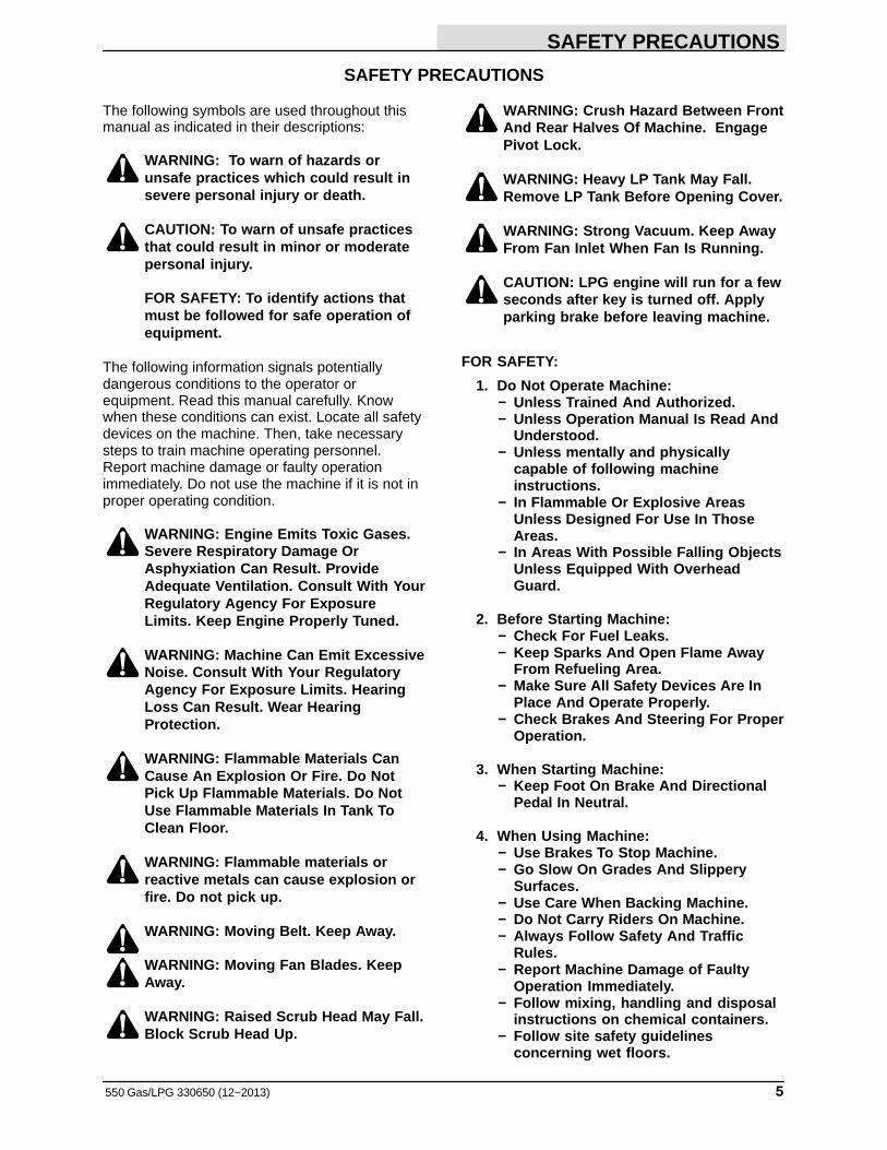
SAFETY PRECAUTIONS
The following symbols are used throughout thismanual as indicated in their descriptions:
WARNING: To warn of hazards orunsafe practices which could result insevere personal injury or death.
CAUTION: To warn of unsafe practicesthat could result in minor or moderatepersonal injury.
FOR SAFETY: To identify actions thatmust be followed for safe operation ofequipment.
The following information signals potentiallydangerous conditions to the operator orequipment. Read this manual carefully. Knowwhen these conditions can exist. Locate all safetydevices on the machine. Then, take necessarysteps to train machine operating personnel.Report machine damage or faulty operationimmediately. Do not use the machine if it is not inproper operating condition.
WARNING: Engine Emits Toxic Gases.Severe Respiratory Damage OrAsphyxiation Can Result. ProvideAdequate Ventilation. Consult With YourRegulatory Agency For ExposureLimits. Keep Engine Properly Tuned.
WARNING: Machine Can Emit ExcessiveNoise. Consult With Your RegulatoryAgency For Exposure Limits. HearingLoss Can Result. Wear HearingProtection.
WARNING: Flammable Materials CanCause An Explosion Or Fire. Do NotPick Up Flammable Materials. Do NotUse Flammable Materials In Tank ToClean Floor.
WARNING: Flammable materials orreactive metals can cause explosion orfire. Do not pick up.
WARNING: Moving Belt. Keep Away.
WARNING: Moving Fan Blades. KeepAway.
WARNING: Raised Scrub Head May Fall.Block Scrub Head Up.
WARNING: Crush Hazard Between FrontAnd Rear Halves Of Machine. EngagePivot Lock.
WARNING: Heavy LP Tank May Fall.Remove LP Tank Before Opening Cover.
WARNING: Strong Vacuum. Keep AwayFrom Fan Inlet When Fan Is Running.
CAUTION: LPG engine will run for a fewseconds after key is turned off. Applyparking brake before leaving machine.
FOR SAFETY:
1. Do Not Operate Machine:− Unless Trained And Authorized.− Unless Operation Manual Is Read And
Understood.− Unless mentally and physically
capable of following machineinstructions.
− In Flammable Or Explosive AreasUnless Designed For Use In ThoseAreas.
− In Areas With Possible Falling ObjectsUnless Equipped With OverheadGuard.
2. Before Starting Machine:− Check For Fuel Leaks.− Keep Sparks And Open Flame Away
From Refueling Area.− Make Sure All Safety Devices Are In
Place And Operate Properly.− Check Brakes And Steering For Proper
Operation.
3. When Starting Machine:− Keep Foot On Brake And Directional
Pedal In Neutral.
4. When Using Machine:− Use Brakes To Stop Machine.− Go Slow On Grades And Slippery
Surfaces.− Use Care When Backing Machine.− Do Not Carry Riders On Machine.− Always Follow Safety And Traffic
Rules.− Report Machine Damage of Faulty
Operation Immediately.− Follow mixing, handling and disposal
instructions on chemical containers.− Follow site safety guidelines
concerning wet floors.
SAFETY PRECAUTIONS
550 Gas/LP 330650 (3−11)6
5. Before Leaving Or Servicing Machine:− Stop On Level Surface.− Set Parking Brake.− Turn Off Machine And Remove Key.
6. When Servicing Machine:− Avoid Moving Parts. Do Not Wear
Loose Jackets, Shirts, Or Sleeves.− Block Machine Tires Before Jacking
Machine Up.− Jack Machine Up At Designated
Locations Only. Block Machine UpWith Jack Stands.
− Use A Hoist Or Jack That Will SupportThe Weight Of The Machine.
− Wear Eye And Ear Protection WhenUsing Pressurized Air Or Water.
− Disconnect Battery ConnectionsBefore Working On Machine.
− Avoid Contact With Battery Acid.− Avoid Contact With Hot Engine
Coolant.− Allow Engine To Cool.− Keep Flames And Sparks Away From
Fuel System Service Area. Keep AreaWell Ventilated.
− Use Cardboard To Locate LeakingHydraulic Fluid Under Pressure.
− Use TENNANT Supplied Or ApprovedReplacement Parts.
7. When loading/unloading machineonto/off truck or trailer:− Turn off machine.− Use truck or trailer that will support
the weight of the machine.− Use winch. Do not drive the machine
onto/off the truck or trailer unless theload height is 380 mm (15 in) or lessfrom the ground.
− Set parking brake after machine isloaded.
− Block machine tires.− Tie machine down to truck or trailer.
SAFETY PRECAUTIONS
7550 Gas/LPG 330650 (3−11)
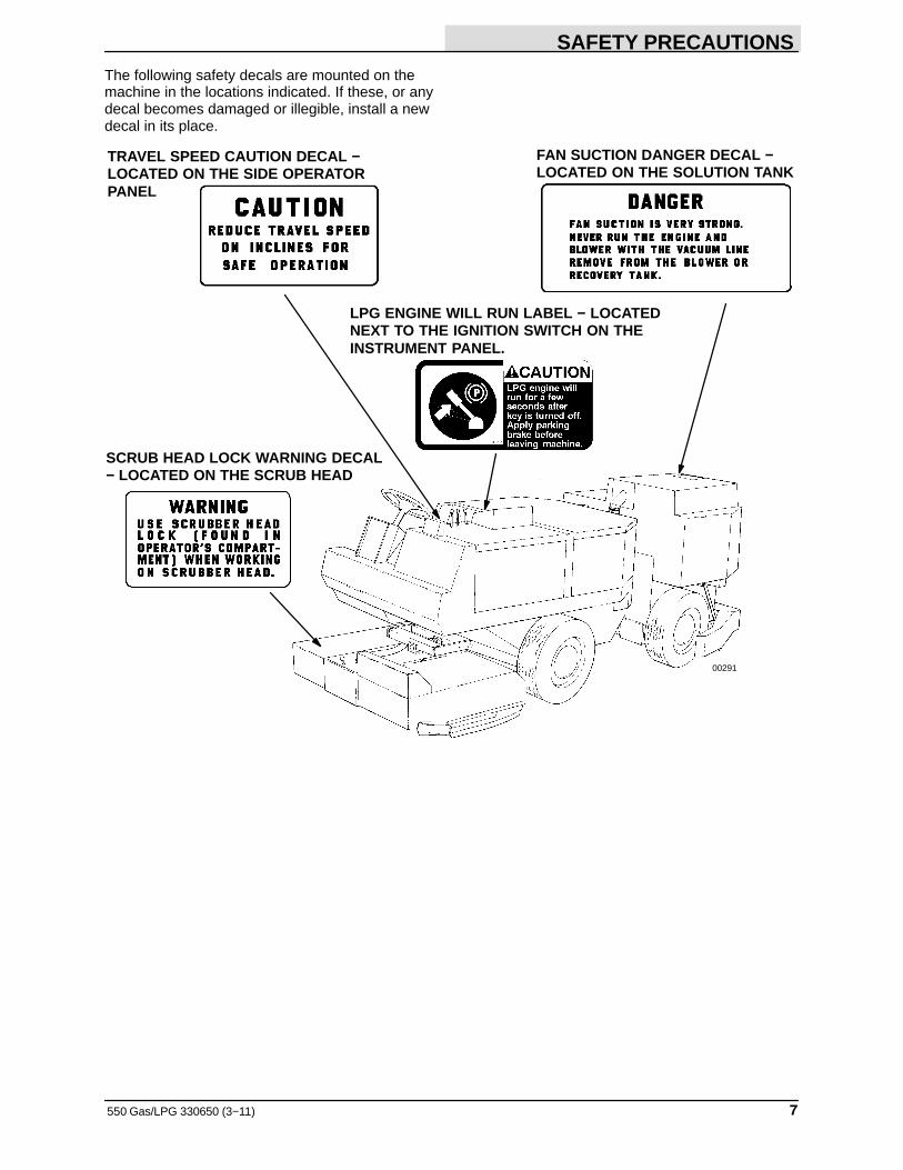
The following safety decals are mounted on themachine in the locations indicated. If these, or anydecal becomes damaged or illegible, install a newdecal in its place.
TRAVEL SPEED CAUTION DECAL −LOCATED ON THE SIDE OPERATORPANEL
SCRUB HEAD LOCK WARNING DECAL− LOCATED ON THE SCRUB HEAD
FAN SUCTION DANGER DECAL −LOCATED ON THE SOLUTION TANK
00291
LPG ENGINE WILL RUN LABEL − LOCATEDNEXT TO THE IGNITION SWITCH ON THEINSTRUMENT PANEL.
SAFETY PRECAUTIONS
550 Gas/LP 330650 (11−07)8
03784
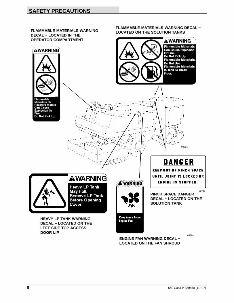
ENGINE FAN WARNING DECAL −LOCATED ON THE FAN SHROUD
00291
03788
PINCH SPACE DANGERDECAL − LOCATED ON THESOLUTION TANK
HEAVY LP TANK WARNINGDECAL − LOCATED ON THELEFT SIDE TOP ACCESSDOOR LIP
FLAMMABLE MATERIALS WARNINGDECAL − LOCATED IN THEOPERATOR COMPARTMENT
FLAMMABLE MATERIALS WARNING DECAL −LOCATED ON THE SOLUTION TANKS
OPERATION
9550 Gas/LPG 330650 (12−99)
PREPARATION FOR OPERATION
AFTER UNLOADING AND BEFOREOPERATING THE MACHINE:
1. Check the machine for shipping damage.
2. Read this manual carefully before operatingor servicing the machine.
FOR SAFETY: Do Not Operate MachineUnless Operation Manual Is Read AndUnderstood.
3. Check the hydraulic fluid level in thehydraulic fluid reservoir, using the dipstickprovided. TENNANT hydraulic fluid isrecommended. If TENNANT hydraulic fluidis not available, use only new, approvedhydraulic fluid. See the HYDRAULICS in theMAINTENANCE section.
4. Check the engine oil level.
5. Check the radiator coolant level.
6. Check the brush adjustment, as described inSCRUB HEAD in the MAINTENANCEsection.
7. Check the air pressure of the tires.
8. Fill the fuel tank, or install an LPG fuel tankon the machine per the instructions in thismanual.
OPERATION
550 Gas/LPG 330650 (11−07)10
OPERATION OF CONTROLS
C
E
D
G
F
I
J
H
A BK
00291
MACHINE COMPONENTS
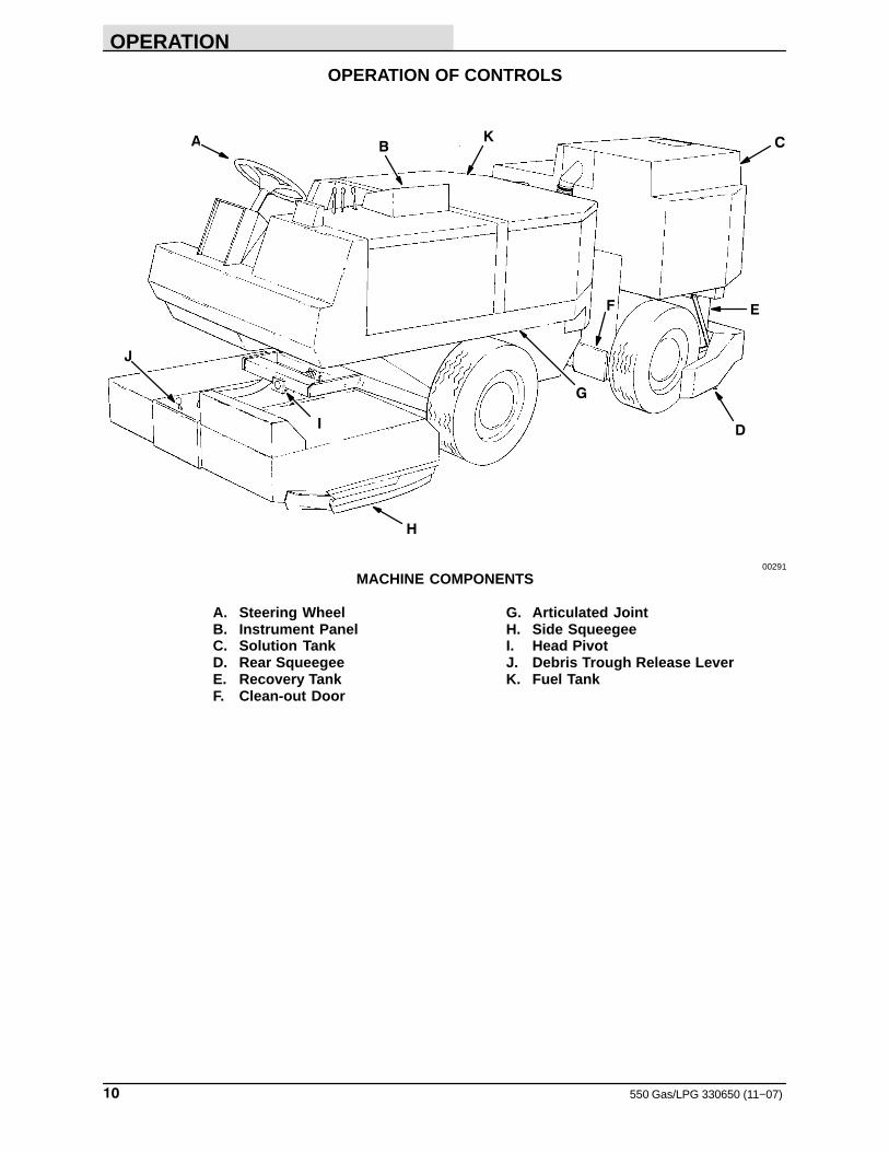
A. Steering Wheel G. Articulated JointB. Instrument Panel H. Side SqueegeeC. Solution Tank I. Head PivotD. Rear Squeegee J. Debris Trough Release LeverE. Recovery Tank K. Fuel TankF. Clean-out Door
OPERATION
11550 Gas/LPG 330650 (2−06)
A
B
C
D
E F
G
H
I
J
K
L
M
N
O
P
QR
S
TU
V
W
X
Y
Z
AA
BB
CC
For machines belowserial number 006409
02353
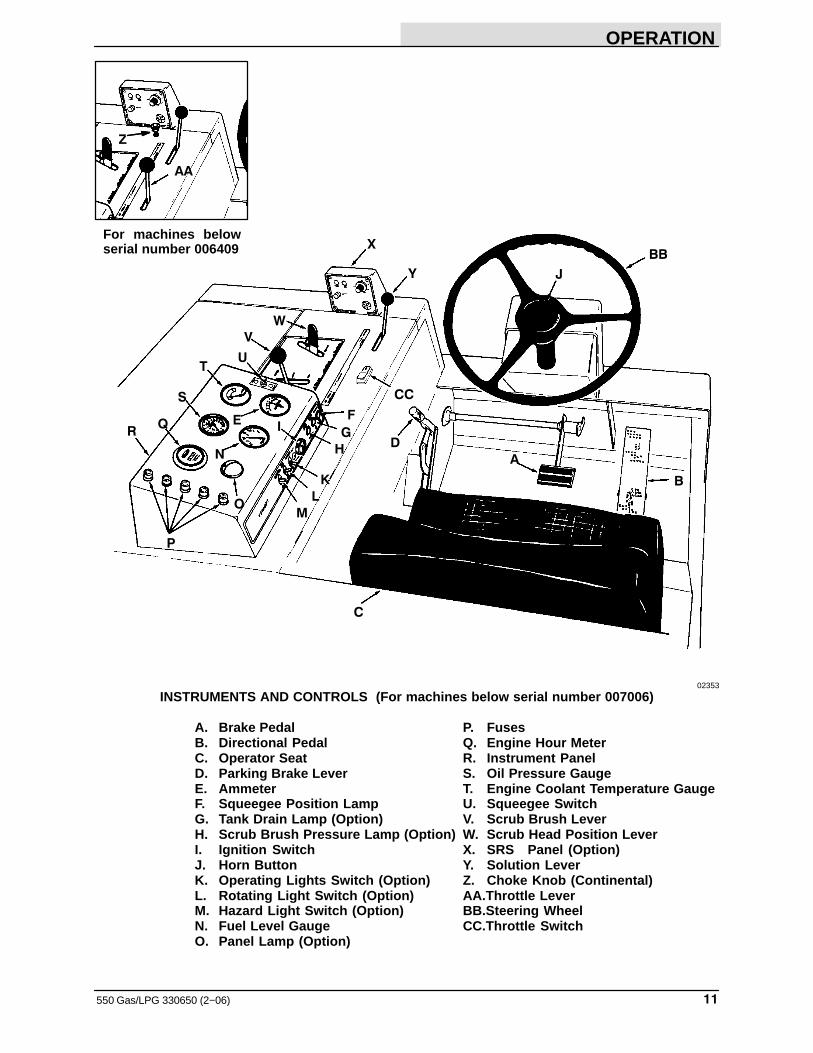
INSTRUMENTS AND CONTROLS (For machines below serial number 007006)
A. Brake Pedal P. FusesB. Directional Pedal Q. Engine Hour MeterC. Operator Seat R. Instrument PanelD. Parking Brake Lever S. Oil Pressure GaugeE. Ammeter T. Engine Coolant Temperature GaugeF. Squeegee Position Lamp U. Squeegee SwitchG. Tank Drain Lamp (Option) V. Scrub Brush LeverH. Scrub Brush Pressure Lamp (Option) W. Scrub Head Position LeverI. Ignition Switch X. SRS Panel (Option)J. Horn Button Y. Solution LeverK. Operating Lights Switch (Option) Z. Choke Knob (Continental)L. Rotating Light Switch (Option) AA.Throttle LeverM. Hazard Light Switch (Option) BB.Steering WheelN. Fuel Level Gauge CC.Throttle SwitchO. Panel Lamp (Option)
OPERATION
550 Gas/LPG 330650 (2−06)12
AB
C
D
EF
G
H
IJ
K
N
Q
L
M
O
P
R
Y
Z
S
T
U
V
X W
02353
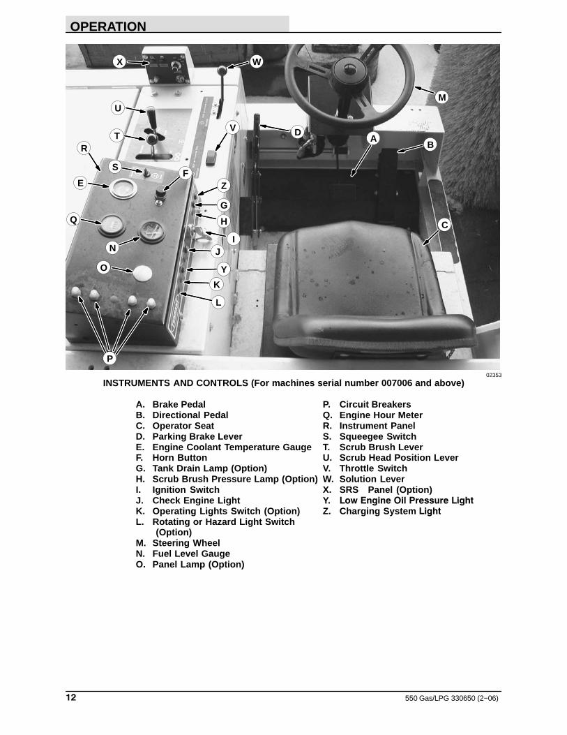
INSTRUMENTS AND CONTROLS (For machines serial number 007006 and above)
A. Brake Pedal P. Circuit BreakersB. Directional Pedal Q. Engine Hour MeterC. Operator Seat R. Instrument PanelD. Parking Brake Lever S. Squeegee SwitchE. Engine Coolant Temperature Gauge T. Scrub Brush LeverF. Horn Button U. Scrub Head Position LeverG. Tank Drain Lamp (Option) V. Throttle SwitchH. Scrub Brush Pressure Lamp (Option) W. Solution LeverI. Ignition Switch X. SRS Panel (Option)J. Check Engine Light Y. Low Engine Oil Pressure LightK. Operating Lights Switch (Option) Z. Charging System LightL. Rotating or Hazard Light Switch
(Option)M. Steering WheelN. Fuel Level GaugeO. Panel Lamp (Option)
OPERATION
13550 Gas/LPG 330650 (2−05)
BRAKE PEDAL
The brake pedal operates the brakes on the twofront wheels.
To stop the machine, return the directional controlpedal to neutral; then apply pressure to the brakepedal.
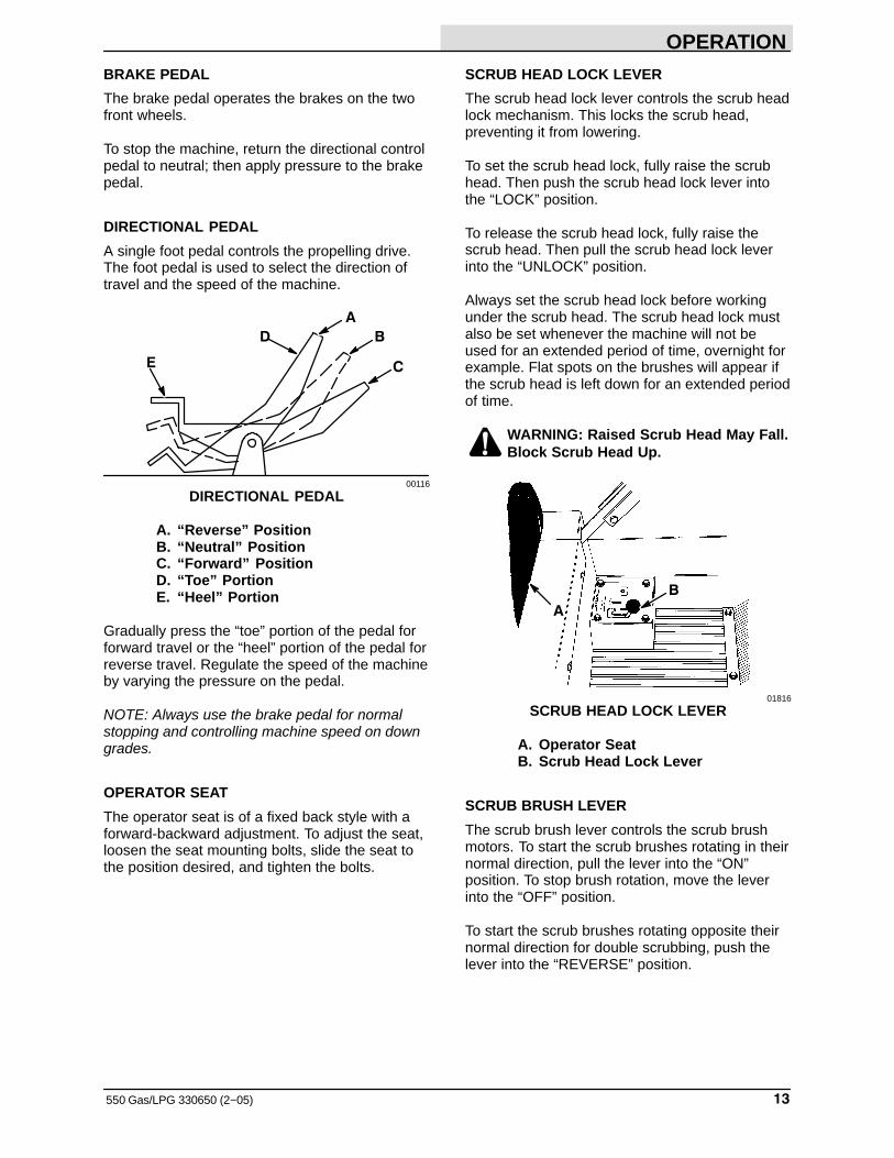
DIRECTIONAL PEDAL
A single foot pedal controls the propelling drive.The foot pedal is used to select the direction oftravel and the speed of the machine.
A
B
CE
D
00116
DIRECTIONAL PEDAL
A. “Reverse” PositionB. “Neutral” PositionC. “Forward” PositionD. “Toe” PortionE. “Heel” Portion
Gradually press the “toe” portion of the pedal forforward travel or the “heel” portion of the pedal forreverse travel. Regulate the speed of the machineby varying the pressure on the pedal.
NOTE: Always use the brake pedal for normalstopping and controlling machine speed on downgrades.
OPERATOR SEAT
The operator seat is of a fixed back style with aforward-backward adjustment. To adjust the seat,loosen the seat mounting bolts, slide the seat tothe position desired, and tighten the bolts.
SCRUB HEAD LOCK LEVER
The scrub head lock lever controls the scrub headlock mechanism. This locks the scrub head,preventing it from lowering.
To set the scrub head lock, fully raise the scrubhead. Then push the scrub head lock lever intothe “LOCK” position.
To release the scrub head lock, fully raise thescrub head. Then pull the scrub head lock leverinto the “UNLOCK” position.
Always set the scrub head lock before workingunder the scrub head. The scrub head lock mustalso be set whenever the machine will not beused for an extended period of time, overnight forexample. Flat spots on the brushes will appear ifthe scrub head is left down for an extended periodof time.
WARNING: Raised Scrub Head May Fall.Block Scrub Head Up.
B
A
01816
SCRUB HEAD LOCK LEVER
A. Operator SeatB. Scrub Head Lock Lever
SCRUB BRUSH LEVER
The scrub brush lever controls the scrub brushmotors. To start the scrub brushes rotating in theirnormal direction, pull the lever into the “ON”position. To stop brush rotation, move the leverinto the “OFF” position.
To start the scrub brushes rotating opposite theirnormal direction for double scrubbing, push thelever into the “REVERSE” position.
OPERATION
550 Gas/LPG 330650 (2−05)14
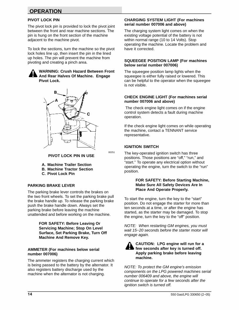
PIVOT LOCK PIN
The pivot lock pin is provided to lock the pivot jointbetween the front and rear machine sections. Thepin is hung on the front section of the machineadjacent to the machine pivot.
To lock the sections, turn the machine so the pivotlock holes line up, then insert the pin in the linedup holes. The pin will prevent the machine frompivoting and creating a pinch area.
WARNING: Crush Hazard Between FrontAnd Rear Halves Of Machine. EngagePivot Lock.
B
C
A
00251
PIVOT LOCK PIN IN USE
A. Machine Trailer SectionB. Machine Tractor SectionC. Pivot Lock Pin
PARKING BRAKE LEVER
The parking brake lever controls the brakes onthe two front wheels. To set the parking brake pullthe brake handle up. To release the parking brakepush the brake handle down. Always set theparking brake before leaving the machineunattended and before working on the machine.
FOR SAFETY: Before Leaving OrServicing Machine; Stop On LevelSurface, Set Parking Brake, Turn OffMachine And Remove Key.
AMMETER (For machines below serialnumber 007006)
The ammeter registers the charging current whichis being passed to the battery by the alternator. Italso registers battery discharge used by themachine when the alternator is not charging.
CHARGING SYSTEM LIGHT (For machinesserial number 007006 and above)
The charging system light comes on when theexisting voltage potential of the battery is notwithin normal range (10 to 14 Volts). Stopoperating the machine. Locate the problem andhave it corrected.
SQUEEGEE POSITION LAMP (For machinesbelow serial number 007006)
The squeegee position lamp lights when thesqueegee is either fully raised or lowered. Thiscan be helpful to the operator when the squeegeeis not visible.
CHECK ENGINE LIGHT (For machines serialnumber 007006 and above)
The check engine light comes on if the enginecontrol system detects a fault during machineoperation.
If the check engine light comes on while operatingthe machine, contact a TENNANT servicerepresentative.
IGNITION SWITCH
The key-operated ignition switch has threepositions. Those positions are “off,” “run,” and“start.” To operate any electrical option withoutoperating the engine, turn the switch to the “run”position.
FOR SAFETY: Before Starting Machine,Make Sure All Safety Devices Are InPlace And Operate Properly.
To start the engine, turn the key to the “start”position. Do not engage the starter for more thanten seconds at a time, or after the engine hasstarted, as the starter may be damaged. To stopthe engine, turn the key to the “off” position.
NOTE: When restarting GM engines, you mustwait 15−20 seconds before the starter motor willengage again.
CAUTION: LPG engine will run for afew seconds after key is turned off.Apply parking brake before leavingmachine.
NOTE: To protect the GM engine’s emissioncomponents on the LPG powered machines serialnumber 006409 and above, the engine willcontinue to operate for a few seconds after theignition switch is turned off.
OPERATION
15550 Gas/LPG 330650 (2−06)
OPERATING LIGHTS SWITCH (OPTION)
The operating lights switch is present onmachines with the operating lights option. Itcontrols the headlights, taillights, and the brushspot light. Flip the switch toggle upward to turnthe lights on. Flip the switch toggle down to turnthe lights off.
ROTATING LIGHT SWITCH (OPTION)
The rotating light switch is present on machineswith the rotating light switch option. Flip the switchtoggle up to turn the light on. Flip the switchtoggle down to turn light off.
HAZARD LIGHT SWITCH (OPTION)
The hazard light switch is present on machineswith the hazard light option. Flip the switch toggleup to turn the light on. Flip the switch toggle downto turn the light off.
FUEL LEVEL GAUGE
The fuel level gauge is present on all gasolinepowered machines. The gauge indicates howmuch fuel is left in the fuel tank.
NOTE: Do not use leaded fuels. The use ofleaded fuels will cause permanent damage to thesystem’s oxygen sensor and catalytic convertor
PANEL LAMP (OPTION)
The panel lamp is present on machines with theoperating lights option. The lamp lights wheneverthe operating lights switch toggle is flipped up toturn on the operating lights.
TANK DRAIN LAMP (OPTION)
The tank drain lamp lights when the recovery tankis nearly full. The machine operator can then planto return to a draining location.
SCRUB BRUSH PRESSURE LAMP (OPTION)
The scrub brush pressure lamp option lights whenscrub brush down pressure is excessive, whichmay cause the brushes to stall. The operatorshould then check the brush position adjustment.
NOTE: This information holds true only after thehydraulic fluid has warmed up (about 10 to 15minutes). If the light comes on after the oil iswarm, the cause may be operating on a roughfloor-use “restricted” brush down pressure.
ENGINE HOUR METER
The hour meter records the number of hours themachine has been operated. This information isuseful in determining when to service themachine.
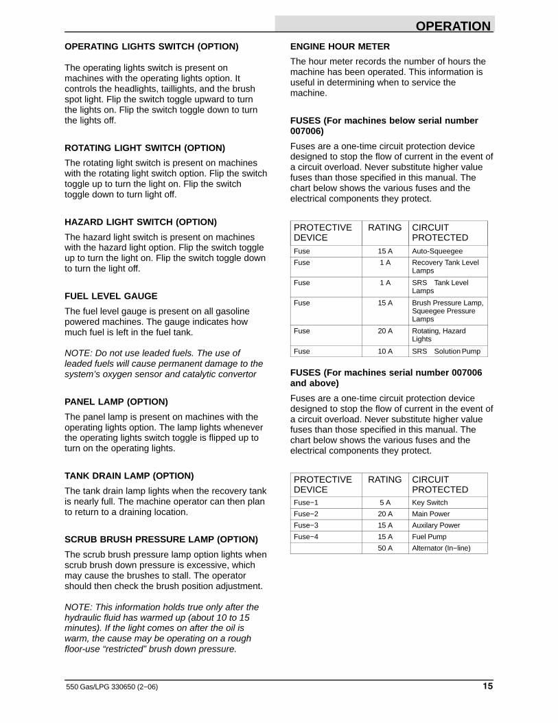
FUSES (For machines below serial number007006)
Fuses are a one-time circuit protection devicedesigned to stop the flow of current in the event ofa circuit overload. Never substitute higher valuefuses than those specified in this manual. Thechart below shows the various fuses and theelectrical components they protect.
PROTECTIVEDEVICE
RATING CIRCUITPROTECTED
Fuse 15 A Auto-Squeegee
Fuse 1 A Recovery Tank LevelLamps
Fuse 1 A SRS Tank LevelLamps
Fuse 15 A Brush Pressure Lamp,Squeegee PressureLamps
Fuse 20 A Rotating, HazardLights
Fuse 10 A SRS Solution Pump
FUSES (For machines serial number 007006and above)
Fuses are a one-time circuit protection devicedesigned to stop the flow of current in the event ofa circuit overload. Never substitute higher valuefuses than those specified in this manual. Thechart below shows the various fuses and theelectrical components they protect.
PROTECTIVEDEVICE
RATING CIRCUITPROTECTED
Fuse−1 5 A Key Switch
Fuse−2 20 A Main Power
Fuse−3 15 A Auxilary Power
Fuse−4 15 A Fuel Pump
50 A Alternator (In−line)
OPERATION
550 Gas/LPG 330650 (2−06)16
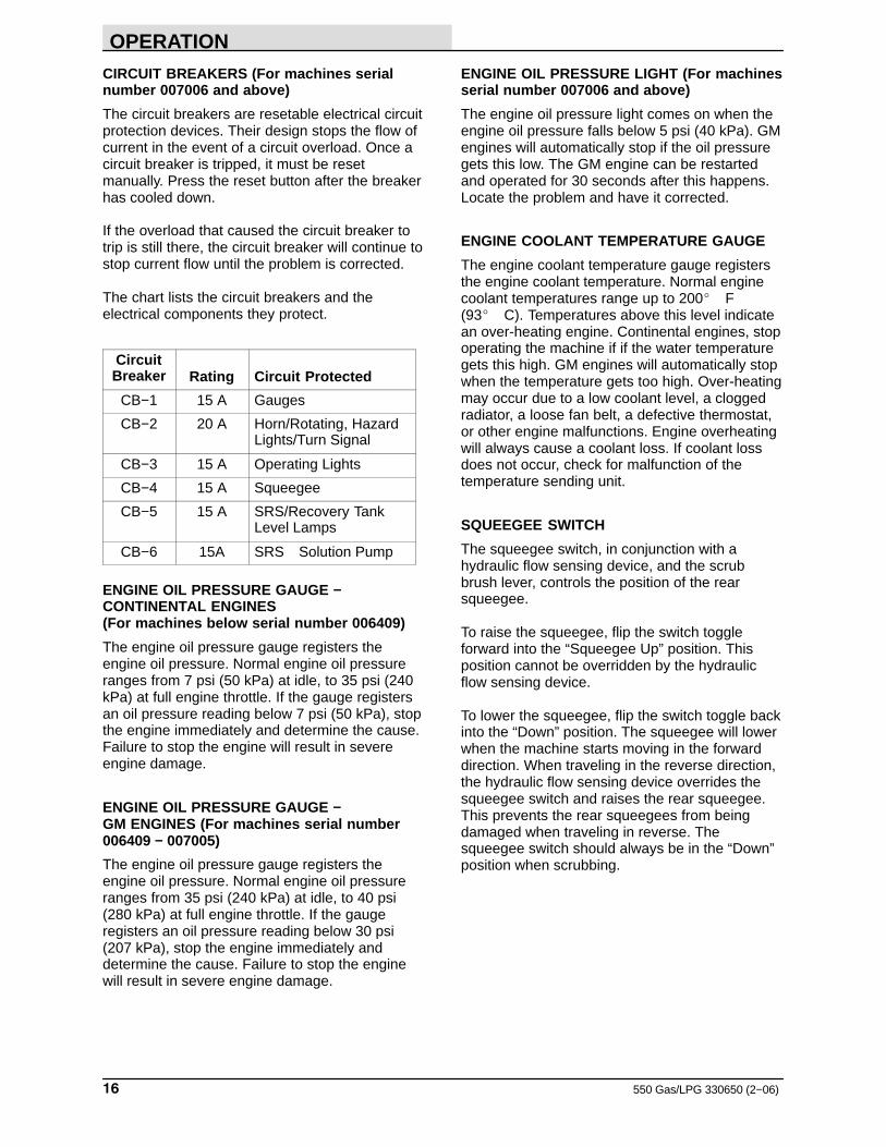
CIRCUIT BREAKERS (For machines serialnumber 007006 and above)
The circuit breakers are resetable electrical circuitprotection devices. Their design stops the flow ofcurrent in the event of a circuit overload. Once acircuit breaker is tripped, it must be resetmanually. Press the reset button after the breakerhas cooled down.
If the overload that caused the circuit breaker totrip is still there, the circuit breaker will continue tostop current flow until the problem is corrected.
The chart lists the circuit breakers and theelectrical components they protect.
CircuitBreaker Rating Circuit Protected
CB−1 15 A Gauges
CB−2 20 A Horn/Rotating, HazardLights/Turn Signal
CB−3 15 A Operating Lights
CB−4 15 A Squeegee
CB−5 15 A SRS/Recovery TankLevel Lamps
CB−6 15A SRS Solution Pump
ENGINE OIL PRESSURE GAUGE −CONTINENTAL ENGINES(For machines below serial number 006409)
The engine oil pressure gauge registers theengine oil pressure. Normal engine oil pressureranges from 7 psi (50 kPa) at idle, to 35 psi (240kPa) at full engine throttle. If the gauge registersan oil pressure reading below 7 psi (50 kPa), stopthe engine immediately and determine the cause.Failure to stop the engine will result in severeengine damage.
ENGINE OIL PRESSURE GAUGE − GM ENGINES (For machines serial number006409 − 007005)
The engine oil pressure gauge registers theengine oil pressure. Normal engine oil pressureranges from 35 psi (240 kPa) at idle, to 40 psi(280 kPa) at full engine throttle. If the gaugeregisters an oil pressure reading below 30 psi(207 kPa), stop the engine immediately anddetermine the cause. Failure to stop the enginewill result in severe engine damage.
ENGINE OIL PRESSURE LIGHT (For machinesserial number 007006 and above)
The engine oil pressure light comes on when theengine oil pressure falls below 5 psi (40 kPa). GMengines will automatically stop if the oil pressuregets this low. The GM engine can be restartedand operated for 30 seconds after this happens.Locate the problem and have it corrected.
ENGINE COOLANT TEMPERATURE GAUGE
The engine coolant temperature gauge registersthe engine coolant temperature. Normal enginecoolant temperatures range up to 200� F (93� C). Temperatures above this level indicatean over-heating engine. Continental engines, stopoperating the machine if if the water temperaturegets this high. GM engines will automatically stopwhen the temperature gets too high. Over-heatingmay occur due to a low coolant level, a cloggedradiator, a loose fan belt, a defective thermostat,or other engine malfunctions. Engine overheatingwill always cause a coolant loss. If coolant lossdoes not occur, check for malfunction of thetemperature sending unit.
SQUEEGEE SWITCH
The squeegee switch, in conjunction with ahydraulic flow sensing device, and the scrubbrush lever, controls the position of the rearsqueegee.
To raise the squeegee, flip the switch toggleforward into the “Squeegee Up” position. Thisposition cannot be overridden by the hydraulicflow sensing device.
To lower the squeegee, flip the switch toggle backinto the “Down” position. The squeegee will lowerwhen the machine starts moving in the forwarddirection. When traveling in the reverse direction,the hydraulic flow sensing device overrides thesqueegee switch and raises the rear squeegee.This prevents the rear squeegees from beingdamaged when traveling in reverse. Thesqueegee switch should always be in the “Down”position when scrubbing.
OPERATION
17550 Gas/LPG 330650 (2−06)
SCRUB HEAD POSITION LEVER
The scrub head position lever controls theposition of the scrub head. To raise the scrubhead, pull the lever back into the “RAISE”position. To stop scrub head movement move thelever to the “HOLD” position. To lower the scrubhead, push the lever into the “LOWER” position.
SRS LIQUID LOW LEVEL LAMPS (OPTION)
The SRS liquid low level lamps option includestwo indicating lamps. The cleaning solution lamplights when the cleaning solution level is low. Therecycling solution lamp lights when the recyclingsolution is low.
A B
C
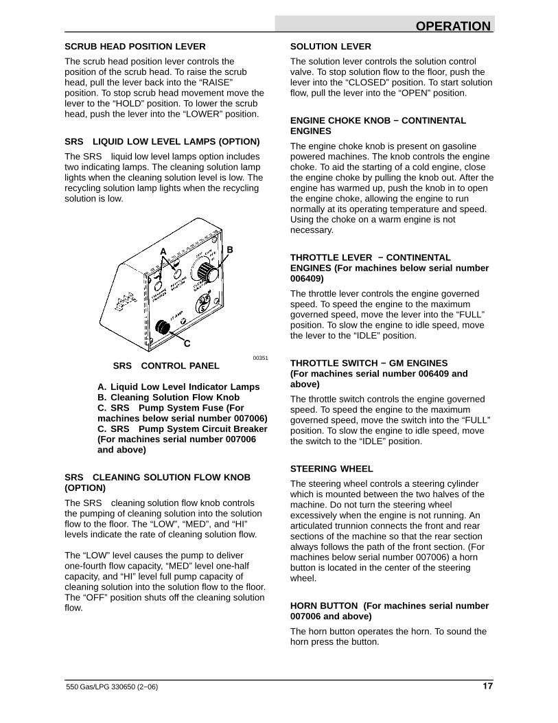
00351
SRS CONTROL PANEL
A. Liquid Low Level Indicator LampsB. Cleaning Solution Flow KnobC. SRS Pump System Fuse (Formachines below serial number 007006)C. SRS Pump System Circuit Breaker(For machines serial number 007006and above)
SRS CLEANING SOLUTION FLOW KNOB(OPTION)
The SRS cleaning solution flow knob controlsthe pumping of cleaning solution into the solutionflow to the floor. The “LOW”, “MED”, and “HI”levels indicate the rate of cleaning solution flow.
The “LOW” level causes the pump to deliverone-fourth flow capacity, “MED” level one-halfcapacity, and “HI” level full pump capacity ofcleaning solution into the solution flow to the floor.The “OFF” position shuts off the cleaning solutionflow.
SOLUTION LEVER
The solution lever controls the solution controlvalve. To stop solution flow to the floor, push thelever into the “CLOSED” position. To start solutionflow, pull the lever into the “OPEN” position.
ENGINE CHOKE KNOB − CONTINENTALENGINES
The engine choke knob is present on gasolinepowered machines. The knob controls the enginechoke. To aid the starting of a cold engine, closethe engine choke by pulling the knob out. After theengine has warmed up, push the knob in to openthe engine choke, allowing the engine to runnormally at its operating temperature and speed.Using the choke on a warm engine is notnecessary.
THROTTLE LEVER − CONTINENTALENGINES (For machines below serial number006409)
The throttle lever controls the engine governedspeed. To speed the engine to the maximumgoverned speed, move the lever into the “FULL”position. To slow the engine to idle speed, movethe lever to the “IDLE” position.
THROTTLE SWITCH − GM ENGINES(For machines serial number 006409 andabove)
The throttle switch controls the engine governedspeed. To speed the engine to the maximumgoverned speed, move the switch into the “FULL”position. To slow the engine to idle speed, movethe switch to the “IDLE” position.
STEERING WHEEL
The steering wheel controls a steering cylinderwhich is mounted between the two halves of themachine. Do not turn the steering wheelexcessively when the engine is not running. Anarticulated trunnion connects the front and rearsections of the machine so that the rear sectionalways follows the path of the front section. (Formachines below serial number 007006) a hornbutton is located in the center of the steeringwheel.
HORN BUTTON (For machines serial number007006 and above)
The horn button operates the horn. To sound thehorn press the button.
OPERATION
550 Gas/LPG 330650 (2−05)18
MACHINE OPERATION
NORMAL SCRUBBING OPERATION
A normal scrubbing operation consists of eighttypical operations: pre-start checklist, startingmachine, filling solution tank, scrubbing, drainingrecovery tank and emptying hopper, postoperation checklist − engine operating, stoppingmachine, and post operation checklist − enginestopped.
PRE-START CHECKLIST lists things to checkbefore starting the machine.
TO START MACHINE lists the steps required tostart the machine.
TO FILL SOLUTION TANK lists the stepsrequired to fill the solution tank.
TO SCRUB lists things to keep in mind before andduring the scrubbing operation.
TO DRAIN RECOVERY TANK AND EMPTYHOPPER lists the steps required to empty thedebris hopper and the recovery tank.
POST OPERATION CHECKLIST − ENGINEOPERATING lists things to check before stoppingthe machine engine.
TO STOP MACHINE lists the steps required tostop the machine.
POST OPERATION CHECKLIST − ENGINESTOPPED lists things to check after stopping themachine engine.
PRE-START CHECKLIST
Check under the machine for leak spots.
Check the engine lubricating oil level.
Check the engine air filter restriction indicator.
Check the fuel level.
Check for LPG odor indicating a leak.
Check for frosting on the LPG hoses andcomponents.
Check to make sure a liquid withdrawal LPG tankis to be used.
Check the brakes and controls for properoperation.
Check the service records to determine servicerequirements.
TO START MACHINE
NOTE: Before starting machine, perform thepre-start checks.
1. LPG machines: Check the LPG fuel tankgauge to see if there is an adequate fuelsupply.
2. LPG machines: Slowly open the liquidservice valve.
NOTE: Opening the service valve too quickly maycause the service valve check valve to stop theflow of LPG fuel. If the check valve stops the flowof fuel, close the service valve, wait a fewseconds, and slowly open the service valve onceagain.
3. The machine operator must be in theoperator’s seat with the directional pedal inthe “neutral” position and with a foot on thebrake pedal or with the parking brake set.
FOR SAFETY: Before Starting Machine,Make Sure All Safety Devices Are InPlace And Operate Properly.
4. Cold CONTINENTAL gasoline engines: Pullout the choke button about three-fourths ofthe way. Push choke in after the engine hasstarted and is running smoothly.
NOTE: Machines with GM engines have an ECU(Electronic Control Unit) which does not requireany cold starting procedures.
ATTENTION! Do not use a cold enginestarting aid such as ether unlessdirected to by a representative of theengine manufacturer.
5. Move the throttle to the “IDLE” position.
OPERATION
19550 Gas/LPG 330650 (2−06)
6. Turn the ignition switch key to the “start”position until the engine starts. Do notoperate the starter for more than tenseconds at a time or after the engine hasstarted.
NOTE: When restarting GM engines, you mustwait 15−20 seconds before the starter motor willengage again.
NOTE: Do not operate the starter motor for moreten seconds at a time or after the engine hasstarted. Allow the starter to cool between startingattempts. The starter motor may be damaged if itis operated incorrectly.
7. Allow the engine and hydraulic system towarm up three to five minutes.
8. Release the machine parking brake.
9. Drive the machine to the solution filling site.
TO FILL SOLUTION TANK
1. Stop the engine and set the parking brake.
FOR SAFETY: Before Leaving OrServicing Machine; Stop On LevelSurface, Set Parking Brake, Turn OffMachine and remove key.
2. Open the solution tank fill door or cap.
WARNING: Flammable Materials CanCause An Explosion Or Fire. Do Not UseFlammable Materials In Tank(s).
3. Pour the required amount of detergent intothe tank. Fill the tank with water to 1 in (25 mm) below the tank opening. The watermust not be hotter than 130�F (54�C) ortank damage may occur.
FOR SAFETY: When using machine,follow mixing and handling instructionson chemical containers.
NOTE: If standing water is to be picked up inaddition to the solution put down by machine, donot fill tank all of the way. This will allow morewater to be picked up before the ball float shutoffis actuated.
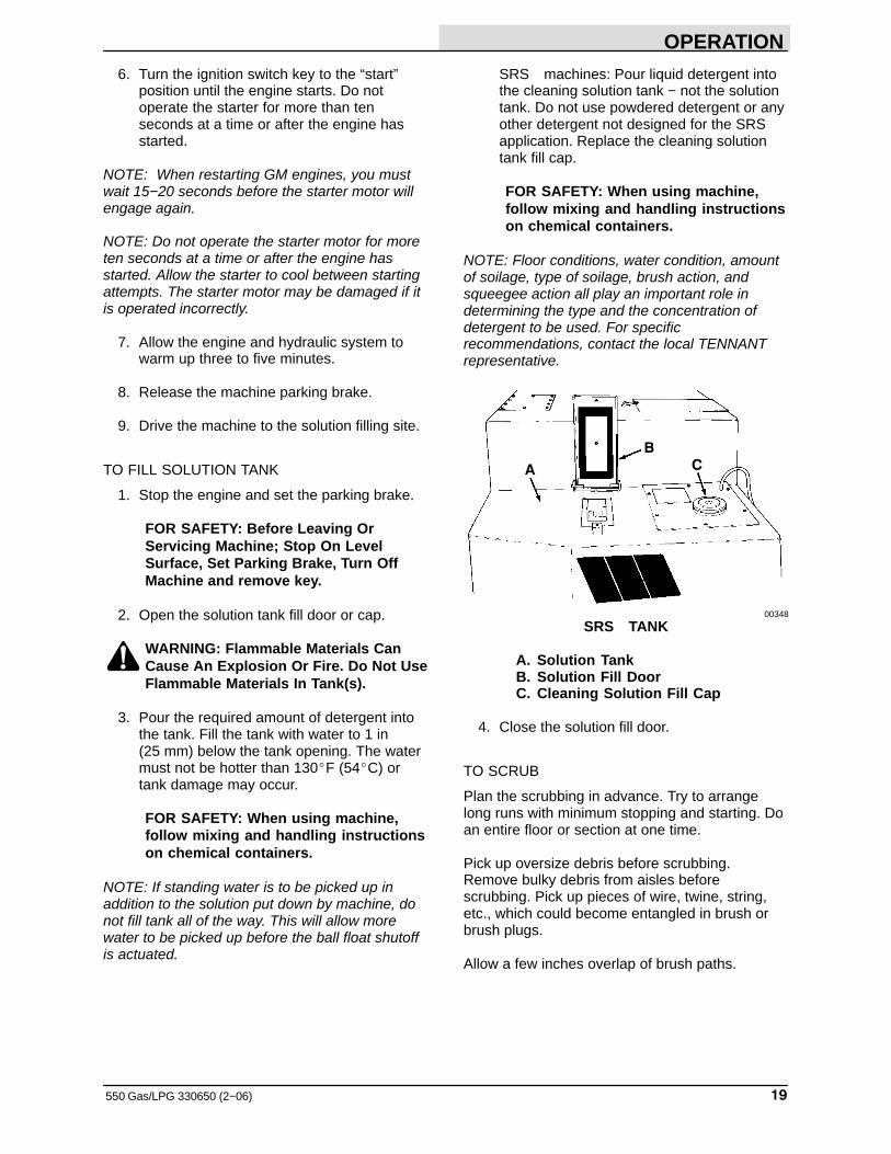
SRS machines: Pour liquid detergent intothe cleaning solution tank − not the solutiontank. Do not use powdered detergent or anyother detergent not designed for the SRSapplication. Replace the cleaning solutiontank fill cap.
FOR SAFETY: When using machine,follow mixing and handling instructionson chemical containers.
NOTE: Floor conditions, water condition, amountof soilage, type of soilage, brush action, andsqueegee action all play an important role indetermining the type and the concentration ofdetergent to be used. For specificrecommendations, contact the local TENNANTrepresentative.
A
BC
00348
SRS TANK
A. Solution TankB. Solution Fill DoorC. Cleaning Solution Fill Cap
4. Close the solution fill door.
TO SCRUB
Plan the scrubbing in advance. Try to arrangelong runs with minimum stopping and starting. Doan entire floor or section at one time.
Pick up oversize debris before scrubbing.Remove bulky debris from aisles beforescrubbing. Pick up pieces of wire, twine, string,etc., which could become entangled in brush orbrush plugs.
Allow a few inches overlap of brush paths.
OPERATION
550 Gas/LPG 330650 (3−11)20
Do not turn steering wheel too sharply when themachine is in motion. It is very responsive to themovement of the steering wheel. Avoid suddenturns, except in emergencies.
Try to scrub as straight a path as possible. Avoidbumping into posts or scraping the sides of themachine.
1. Drive the machine to the area to bescrubbed.
2. Move the scrub head position lever to the“RAISE” position to release the scrub headlock.
3. Move the scrub head lock lever to the“UNLOCK” position.
4. Place the squeegee switch in the “Down”position.
5. Move the solution lever back to start thesolution flow.
For SRS machines: Turn the cleaningsolution knob to the desired cleaningsolution flow.
6. Move the scrub brush lever to the “ON”position.
7. Scrub as required.
WARNING: Flammable materials orreactive metals can cause explosion orfire. Do not pick up.
TO DRAIN AND CLEAN RECOVERY TANK ANDEMPTY HOPPER
1. Stop the engine and set the parking brake.
FOR SAFETY: Before Leaving OrServicing Machine; Stop On LevelSurface, Set Parking Brake, Turn OffMachine And Remove Key.
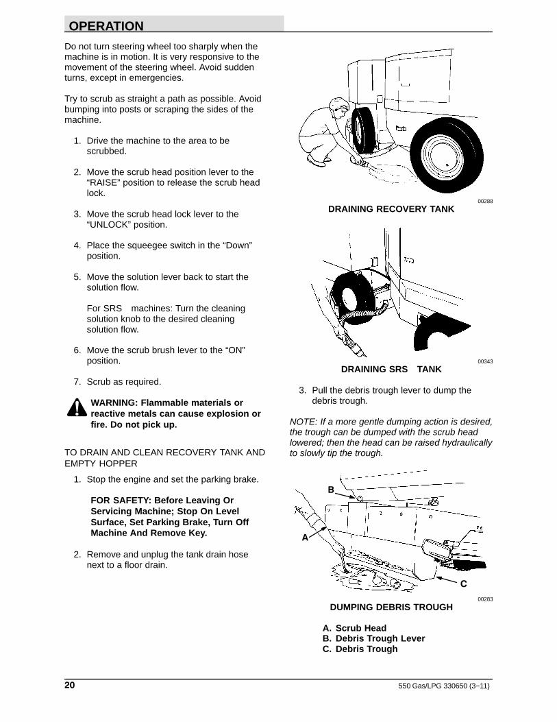
2. Remove and unplug the tank drain hosenext to a floor drain.
00288
DRAINING RECOVERY TANK
00343
DRAINING SRS TANK
3. Pull the debris trough lever to dump thedebris trough.
NOTE: If a more gentle dumping action is desired,the trough can be dumped with the scrub headlowered; then the head can be raised hydraulicallyto slowly tip the trough.
B
C
A
00283
DUMPING DEBRIS TROUGH
A. Scrub HeadB. Debris Trough LeverC. Debris Trough
OPERATION
21550 Gas/LPG 330650 (3−11)
4. Clean the trough screen.
5. Clean the channel above the debris trough.If debris builds up in this area, the trough willnot swing all the way up and latch properly.Remove any debris which has accumulatedon top of the rail.
6. Close the debris trough.
7. Plug and secure the drain hose to themachine after tank is drained.
8. SRS machines: Partially fill the solution tankwith clean water. Run the SRS pump for afew minutes to flush the solution hoses.
POST OPERATION CHECKLIST − ENGINEOPERATING
Check the scrub brush pattern for width andevenness.
Check the squeegees for proper deflection.
TO STOP MACHINE
1. Return the directional pedal to the “neutral”position. Apply the brake.
2. Move the solution lever to the “OFF”position.
3. Move the scrub head position lever to the“RAISE” position to set the scrub head lock.
4. Move the scrub head lock lever to the“LOCK” position.
5. Move the scrub brush lever to the “OFF”position.
6. Place the squeegee switch in the “SqueegeeUp” position.
7. Turn off the operating lights if used.
8. Place the throttle in the “IDLE” position.
9. Set the machine parking brake.
FOR SAFETY: Before Leaving OrServicing Machine; Stop On LevelSurface, Set Parking Brake, Turn OffMachine And Remove Key.
10. Turn the ignition key switch to the “off”position. Remove the ignition key from theignition switch.
11. LPG powered machines: Close the LPGtank liquid service valve.
POST OPERATION CHECKLIST − ENGINESTOPPED
Check for wire or string tangled on the scrubbrushes.
Check the squeegees for wear or damage.
Empty and clean the debris hopper.
Drain and clean the recovery tank.
Check the vacuum hoses for debris orobstructions.
Fill the fuel tank.
Check for leaks.
DOUBLE SCRUBBING OPERATION
Double pass scrubbing should be necessary onlyfor heavy soilage and build-up of dirt, wax, etc.Operate the machine as desired for normalscrubbing but keep the rear squeegee up whilemaking the first scrubbing pass. Allow the solutionto soak on the floor for 15 to 20 minutes. Thenmake a second pass in the normal manner withthe rear squeegee down.
FOR SAFETY: When Using Machine, GoSlow On Grades And Slippery Surfaces.
OPERATION ON GRADES
Drive the machine slowly on grades. Some loss ofrear wheel steering traction could occur whenbraking with empty solution tanks.
The maximum rated ramp climb angle is 10�.
FOR SAFETY: When Using Machine, GoSlow On Grades And Slippery Surfaces.
OPERATION
550 Gas/LPG 330650 (12−99)22
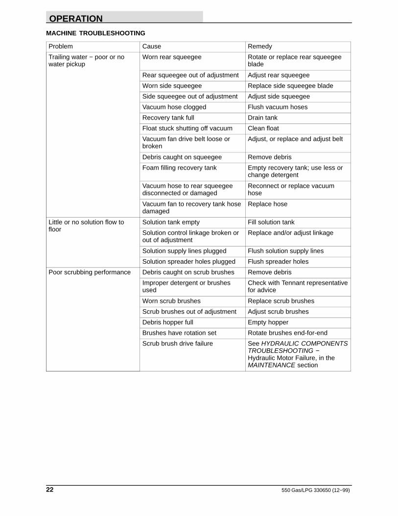
MACHINE TROUBLESHOOTING
Problem Cause Remedy
Trailing water − poor or nowater pickup
Worn rear squeegee Rotate or replace rear squeegeeblade
Rear squeegee out of adjustment Adjust rear squeegee
Worn side squeegee Replace side squeegee blade
Side squeegee out of adjustment Adjust side squeegee
Vacuum hose clogged Flush vacuum hoses
Recovery tank full Drain tank
Float stuck shutting off vacuum Clean float
Vacuum fan drive belt loose orbroken
Adjust, or replace and adjust belt
Debris caught on squeegee Remove debris
Foam filling recovery tank Empty recovery tank; use less orchange detergent
Vacuum hose to rear squeegeedisconnected or damaged
Reconnect or replace vacuumhose
Vacuum fan to recovery tank hosedamaged
Replace hose
Little or no solution flow tofloor
Solution tank empty Fill solution tank
Solution control linkage broken orout of adjustment
Replace and/or adjust linkage
Solution supply lines plugged Flush solution supply lines
Solution spreader holes plugged Flush spreader holes
Poor scrubbing performance Debris caught on scrub brushes Remove debris
Improper detergent or brushesused
Check with Tennant representativefor advice
Worn scrub brushes Replace scrub brushes
Scrub brushes out of adjustment Adjust scrub brushes
Debris hopper full Empty hopper
Brushes have rotation set Rotate brushes end-for-end
Scrub brush drive failure See HYDRAULIC COMPONENTSTROUBLESHOOTING −Hydraulic Motor Failure, in theMAINTENANCE section
OPERATION
23550 Gas/LPG 330650 (8−01)
OPTIONS OPERATION
HIGH PRESSURE SPRAYER
The high pressure sprayer option gives themachine the ability to spray wash grease, oil, andother dirt from trucks, racks, walls, etc. The waterand detergent solution is taken from the solutionsupply line located under the operator seat. Thesolution is directed first to the spray pump whichis driven off the machine hydraulic system. Thespray pump has a 4 gpm (15 L/min) capacity upto 800 psi (5515 kPa). From the pump, the waterflows through the hand-held sprayer.
NOTE: Pump only approved machine detergentsand solutions through the high pressure sprayer.Acids and abrasive fluids may damage the unit.
The engine idle must be set between 700 and 850 rpm to allow the pump to operate at normalspeed.
TO OPERATE HIGH PRESSURE SPRAYER
1. Set the machine parking brake.
FOR SAFETY: Before Leaving OrServicing Machine; Stop On LevelSurface, Set Parking Brake, Turn OffMachine And Remove Key.
2. Start engine. Move the throttle to the “IDLE”position.
ATTENTION! Do not operate the highpressure sprayer at full engine throttleor the water pump will fail.
3. Open the shutoff valve on the scrub head.
4. Adjust water pressure to 800 psi (5515 kPa)using red pressure adjustment knob onregulator.
FOR SAFETY: When Servicing Machine,Wear Eye And Ear Protection WhenUsing Pressurized Air Or Water.
5. Spray as required.
NOTE: Check the water spray pressure. It is to be600 to 800 psi (4140 to 5515 kPa) when operatingthe sprayer. The maximum pressure when notspraying is 1200 psi (8275 kPa). To change thewater pressure, adjust the red pressureadjustment knob on the regulator, or adjust theengine idle.
6. When finished, close the shutoff valve andrelieve water pressure in the high pressurespray hose. Place all equipment in its properstorage location.
VACUUM WAND
The vacuum wand option gives the machine theadded flexibility of picking up spills not accessibleby the machine. A 20 ft (6095 mm) hose andwand utilizes the machine vacuum system.
TO OPERATE VACUUM WAND
1. Set the machine parking brake.
FOR SAFETY: Before Leaving OrServicing Machine; Stop On LevelSurface, Set Parking Brake, Turn OffMachine And Remove Key.
2. Remove the vacuum wand and hose fromstorage on the machine.
3. Remove the rear squeegee vacuum hoseplate from the rear of the tank.
4. Attach the vacuum wand hose plate to therear of the tank using the toggle clampsprovided.
5. Start the engine.
6. Move the throttle to the “FULL” position.
7. Operate the vacuum wand as required.
WARNING: Flammable materials orreactive metals can cause explosion orfire. Do not pick up.
8. When finished, stop the engine, and removethe vacuum wand hose plate from the rearof the tank.
9. Reconnect the rear squeegee vacuum hoseplate to the rear of the tank using the toggleclamps provided.
10. Clean and rinse off the vacuum wand, hose,and related equipment as required.
11. Store the vacuum wand equipment in theproper locations.
OPERATION
550 Gas/LPG 330650 (9−00)24
TOWING AND TRANSPORTING THE MACHINE
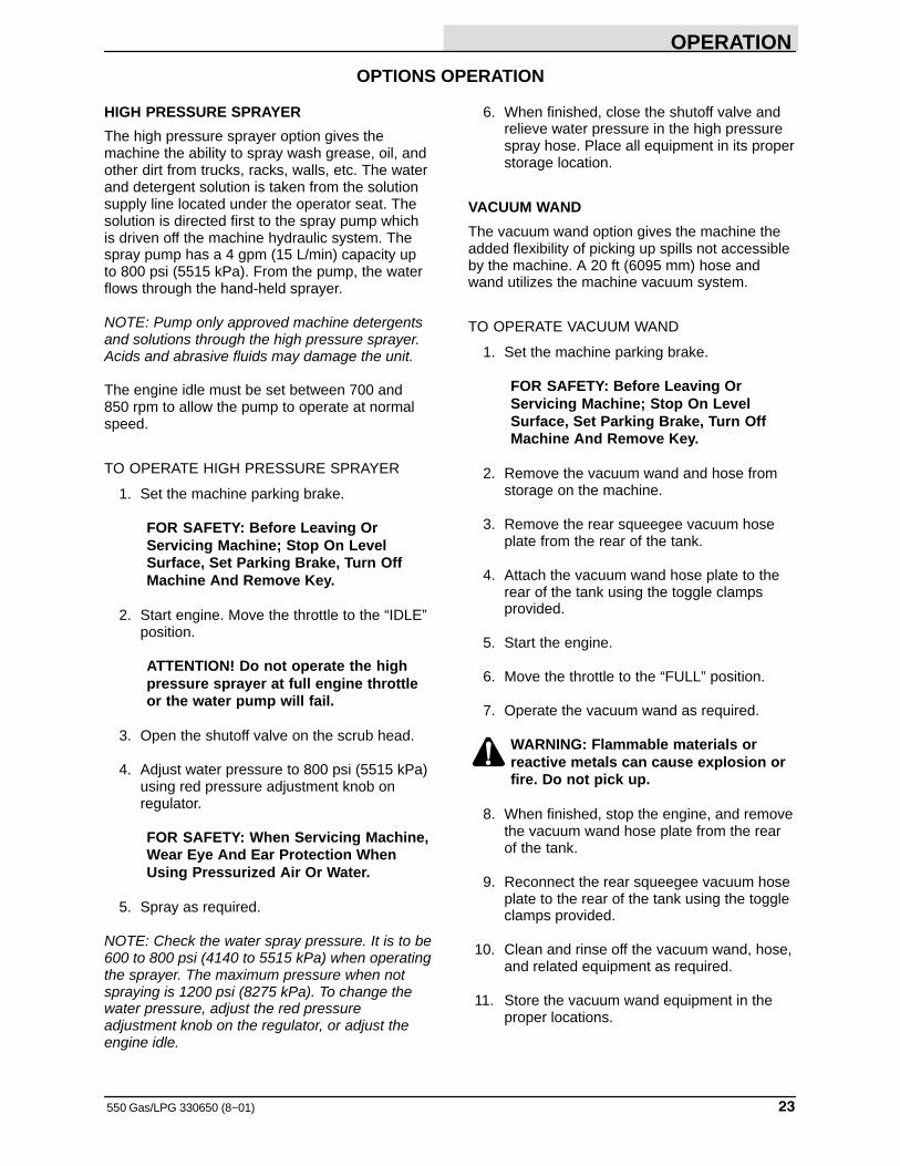
TOWING THE MACHINE
If the machine becomes disabled, it can be towedfrom the front or rear using the towing bracketslocated at the front or rear of the machine. Thismachine is not designed to be pushed.
A
TOWING BRACKET
A. Towing Bracket
The propelling pump has a bypass valve toprevent damage to the hydraulic system when themachine is being towed. This valve allows adisabled machine to be moved a very shortdistance and at a speed to not exceed 1.6 kp/h (1 mph). The machine is NOT intended to betowed a long distance or at a high speed.
ATTENTION! Do not tow machine for along distance and without using thebypass valve, or the machine hydraulicsystem may be damaged.
A
B
BYPASS VALVE
A. Bypass ValveB. Propelling Pump
Turn the bypass valve 90� from the normalposition before towing the machine.
TRANSPORTING THE MACHINE
1. Position the machine at the loading edge ofthe truck or trailer.
FOR SAFETY: Use truck or trailer thatwill support the weight of the machine.
NOTE: Empty the recovery and solution tanksbefore transporting the machine.
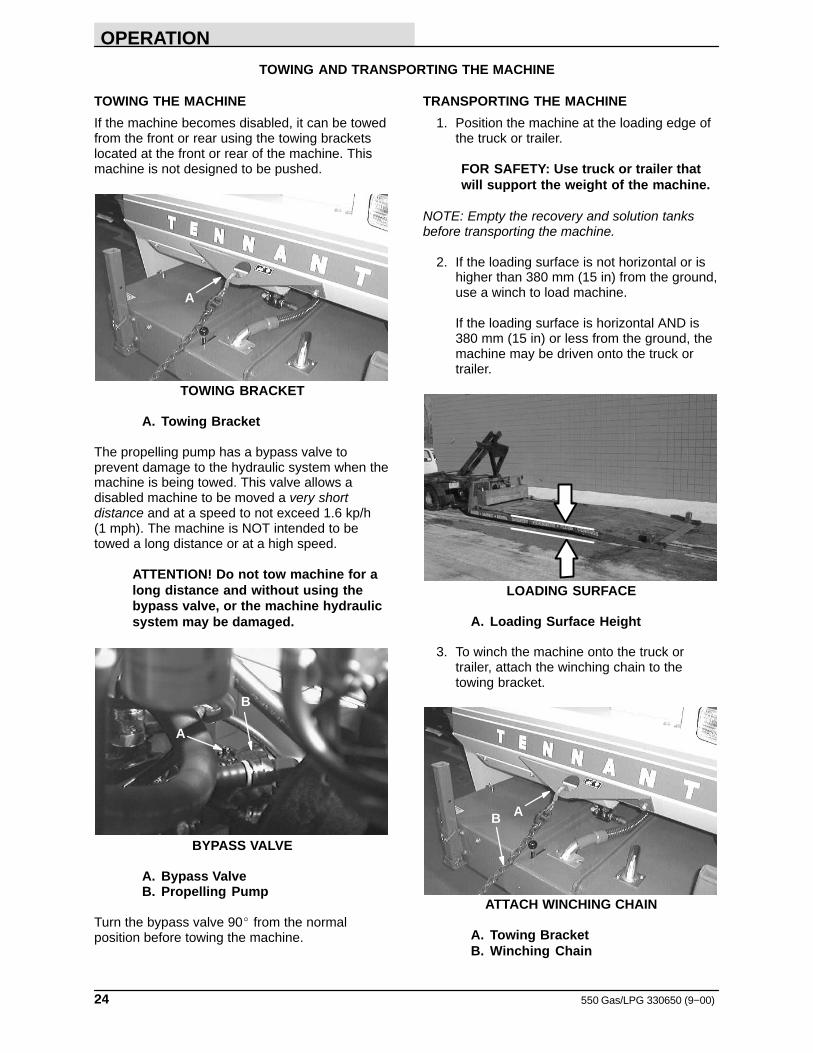
2. If the loading surface is not horizontal or ishigher than 380 mm (15 in) from the ground,use a winch to load machine.
If the loading surface is horizontal AND is380 mm (15 in) or less from the ground, themachine may be driven onto the truck ortrailer.
LOADING SURFACE
A. Loading Surface Height
3. To winch the machine onto the truck ortrailer, attach the winching chain to thetowing bracket.
AB
ATTACH WINCHING CHAIN
A. Towing BracketB. Winching Chain
OPERATION
25550 Gas/LPG 330650 (9−00)
4. Turn the bypass valve 90� from the normalposition before winching the machine ontothe truck or trailer. See TOWING THEMACHINE section of this manual. Makesure the machine is centered.
FOR SAFETY: When loading machineonto truck or trailer, use winch. Do notdrive the machine onto the truck ortrailer unless the loading surface ishorizontal AND is 380 mm (15 in) or lessfrom the ground.
A
B
BYPASS VALVE
A. Bypass ValveB. Propelling Pump
5. Turn the machine so the pivot lock holes lineup, then insert the pin in the lined up holes.The pin will prevent the machine frompivoting and creating a pinch area. SeePIVOT LOCK PIN section of this manual.
WARNING: Crush Hazard Between FrontAnd Rear Halves Of Machine. EngagePivot Lock.
B
C
A
00251
PIVOT LOCK PIN IN USE
A. Machine Trailer SectionB. Machine Tractor SectionC. Pivot Lock Pin
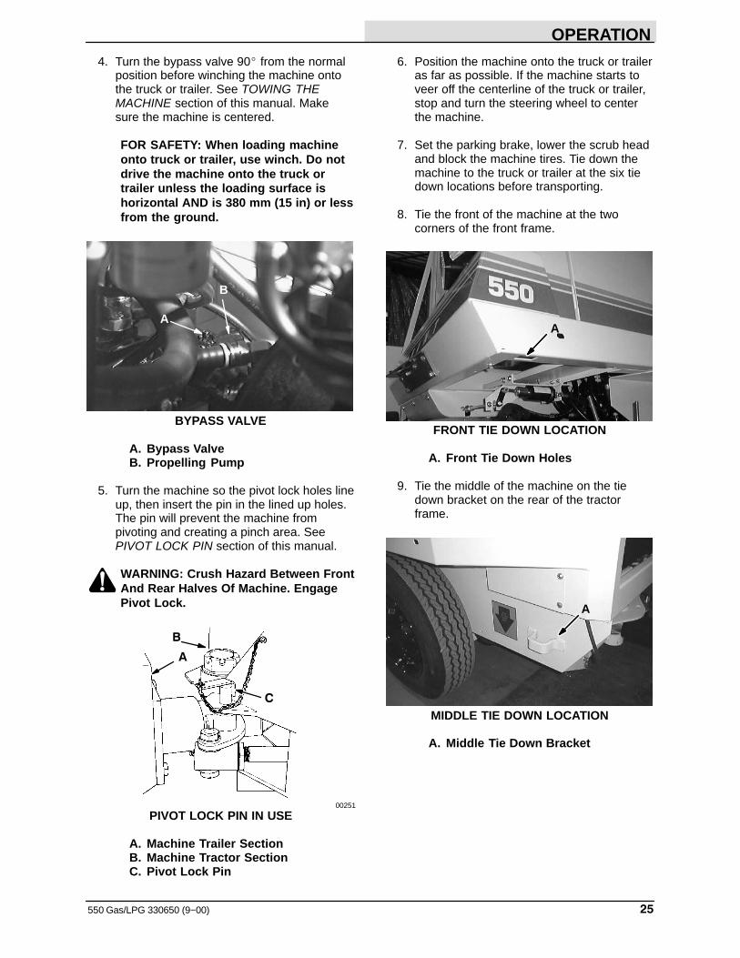
6. Position the machine onto the truck or traileras far as possible. If the machine starts toveer off the centerline of the truck or trailer,stop and turn the steering wheel to centerthe machine.
7. Set the parking brake, lower the scrub headand block the machine tires. Tie down themachine to the truck or trailer at the six tiedown locations before transporting.
8. Tie the front of the machine at the twocorners of the front frame.
A
FRONT TIE DOWN LOCATION
A. Front Tie Down Holes
9. Tie the middle of the machine on the tiedown bracket on the rear of the tractorframe.
A
MIDDLE TIE DOWN LOCATION
A. Middle Tie Down Bracket
OPERATION
550 Gas/LPG 330650 (9−00)26
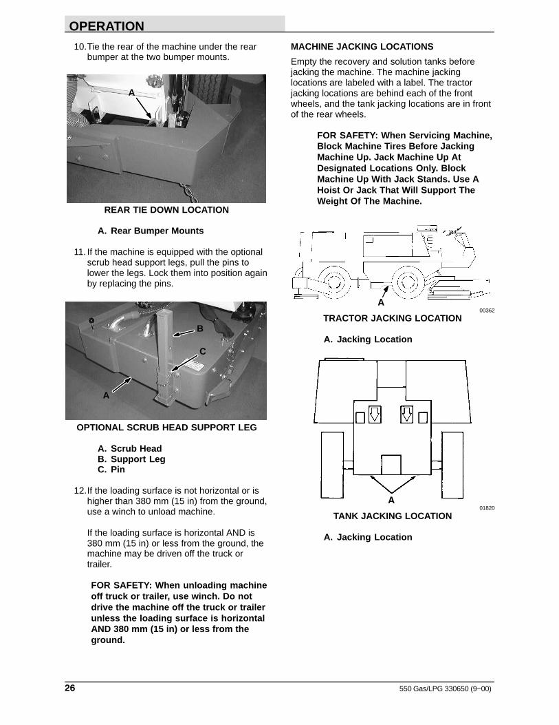
10.Tie the rear of the machine under the rearbumper at the two bumper mounts.
A
REAR TIE DOWN LOCATION
A. Rear Bumper Mounts
11. If the machine is equipped with the optionalscrub head support legs, pull the pins tolower the legs. Lock them into position againby replacing the pins.
A
B
C
OPTIONAL SCRUB HEAD SUPPORT LEG
A. Scrub HeadB. Support LegC. Pin
12.If the loading surface is not horizontal or ishigher than 380 mm (15 in) from the ground,use a winch to unload machine.
If the loading surface is horizontal AND is380 mm (15 in) or less from the ground, themachine may be driven off the truck ortrailer.
FOR SAFETY: When unloading machineoff truck or trailer, use winch. Do notdrive the machine off the truck or trailerunless the loading surface is horizontalAND 380 mm (15 in) or less from theground.
MACHINE JACKING LOCATIONS
Empty the recovery and solution tanks beforejacking the machine. The machine jackinglocations are labeled with a label. The tractorjacking locations are behind each of the frontwheels, and the tank jacking locations are in frontof the rear wheels.
FOR SAFETY: When Servicing Machine,Block Machine Tires Before JackingMachine Up. Jack Machine Up AtDesignated Locations Only. BlockMachine Up With Jack Stands. Use AHoist Or Jack That Will Support TheWeight Of The Machine.
A00362
TRACTOR JACKING LOCATION
A. Jacking Location
A01820
TANK JACKING LOCATION
A. Jacking Location
OPERATION
27550 Gas/LPG 330650 (8−01)
MACHINE STORAGE
STORING MACHINE
When storing the machine for extended periods oftime, the following procedures must be followed toreduce the chance of rust, sludge, and otherundesirable deposits to form:
1. Drain and clean out the solution recoveryand cleaning solution tanks.
2. Add ‘Stabil’ or equivalent fuel conditioner tothe fuel tank as recommended on the bottle.Run the engine approximately 10 to 15minutes to insure that the treated fuel iscompletely through the fuel system.
2. Park the machine in a cool and dry area.
3. Stop the engine and set the machineparking brake.
FOR SAFETY: Before Leaving OrServicing Machine; Stop On LevelSurface, Set Parking Brake, Turn OffMachine And Remove Key.
LPG powered machines: Close the LPGtank liquid service valve.
4. Raise and lock the scrub head.
5. Fill the hydraulic reservoir with hydraulic fluidto the full mark on the dipstick, to preventexcessive condensation from forming in thereservoir.
GASOLINE POWERED MACHINES
To store the machine 30 to 90 days:
1. Park the machine in a cool and dry area.
2. Stop the engine and set the machineparking brake.
FOR SAFETY: Before Leaving OrServicing Machine; Stop On LevelSurface, Set Parking Brake, Turn OffMachine And Remove Key.
3. Change engine oil and oil filter.
4. Remove the spark plugs.
5. Pour 3 oz. (90 cc) of clean engine oil intoeach spark plug hole.
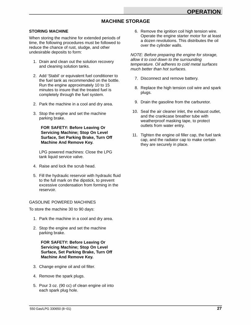
6. Remove the ignition coil high tension wire.Operate the engine starter motor for at leasta dozen revolutions. This distributes the oilover the cylinder walls.
NOTE: Before preparing the engine for storage,allow it to cool down to the surroundingtemperature. Oil adheres to cold metal surfacesmuch better than hot surfaces.
7. Disconnect and remove battery.
8. Replace the high tension coil wire and sparkplugs.
9. Drain the gasoline from the carburetor.
10. Seal the air cleaner inlet, the exhaust outlet,and the crankcase breather tube withweatherproof masking tape, to protectoutlets from water entry.
11. Tighten the engine oil filler cap, the fuel tankcap, and the radiator cap to make certainthey are securely in place.
OPERATION
550 Gas/LPG 330650 (8−01)28
To store the machine 90 days to 6 months:
1. Park the machine in a cool and dry area.
2. Stop the engine and set the machineparking brake.
FOR SAFETY: Before Leaving OrServicing Machine; Stop On LevelSurface, Set Parking Brake, Turn OffMachine And Remove Key.
3. Remove the spark plugs.
4. Pour 3 oz (90 ml) of clean engine oil intoeach spark plug hole.
5. Remove the ignition coil high tension wire.Operate the engine starter motor for at leasta dozen revolutions. This distributes the oilover the cylinder walls.
NOTE: Before preparing the engine for storage,allow it to cool down to the surroundingtemperature. Oil adheres to cold metal surfacesmuch better than hot surfaces.
6. Replace the high tension coil wire and sparkplugs.
7. Disconnect and remove battery.
8. Drain the engine oil.
9. Drain the engine coolant from the radiator,and the engine block.
10. Close the drain cocks.
11. Drain gasoline from the carburetor, fuel tank,and the fuel lines.
12. Seal the air cleaner inlet, the exhaust outlet,and the crankcase breather tube withweatherproof masking tape, to protectoutlets from water entry.
13. Tighten the engine oil filler cap, the fuel tankcap, and the radiator cap to make certainthey are securely in place.
MAINTENANCE
29550 Gas/LPG 330650 (8−02)
RECOMMENDED FIRST 50-HOUR MACHINE INSPECTION
After the first 50 hours of operation, the followingprocedures are recommended:
FOR SAFETY: Before Leaving OrServicing Machine; Stop On LevelSurface, Set Parking Brake, Turn OffMachine and remove key.
1. Check the air filter element. Tighten allconnections on intake hose, air filter, etc.
2. Change engine oil and filter.
3. Check for the correct alternator and vacuumfan belt tension.
WARNING: Moving Fan Blades. KeepAway.
4. Check the scrub brush pattern.
5. Check the scrub head side squeegee bladesfor wear or damage.
6. Check the rear squeegee for worn ordamaged blades or for incorrect adjustment.
7. Check vacuum hoses for damage or looseconnections.
8. Check engine valve tappet clearance.
9. Torque the cylinder head bolts to the properspecification.
10. Perform all remaining 50-hour lubricationand maintenance procedures listed in theMAINTENANCE CHART.
MAINTENANCE
550 Gas/LPG 330650 (2−06)30
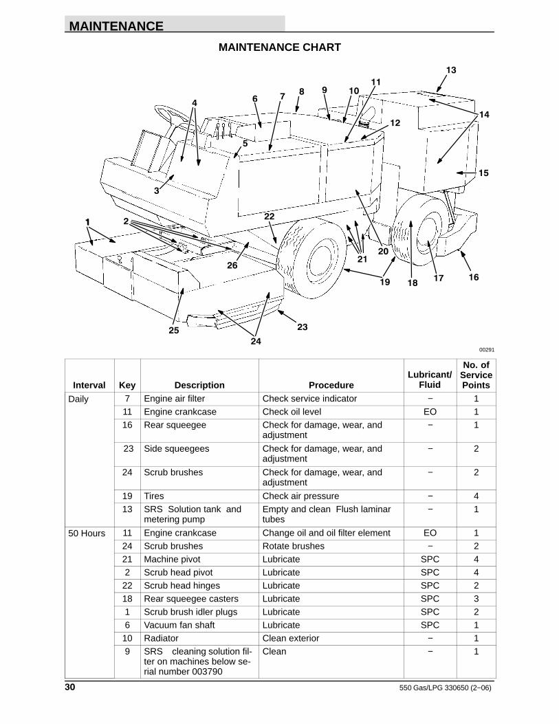
MAINTENANCE CHART
2
3
4
5
6 78 9 10
11
12
13
14
15
16171819
2021
2211
26
25 23
2400291
Interval Key Description ProcedureLubricant/
Fluid
No. ofServicePoints
Daily 7 Engine air filter Check service indicator − 111 Engine crankcase Check oil level EO 116 Rear squeegee Check for damage, wear, and
adjustment− 1
23 Side squeegees Check for damage, wear, andadjustment
− 2
24 Scrub brushes Check for damage, wear, andadjustment
− 2
19 Tires Check air pressure − 413 SRS Solution tank and
metering pumpEmpty and clean Flush laminartubes
− 1
50 Hours 11 Engine crankcase Change oil and oil filter element EO 124 Scrub brushes Rotate brushes − 221 Machine pivot Lubricate SPC 42 Scrub head pivot Lubricate SPC 4
22 Scrub head hinges Lubricate SPC 218 Rear squeegee casters Lubricate SPC 31 Scrub brush idler plugs Lubricate SPC 26 Vacuum fan shaft Lubricate SPC 1
10 Radiator Clean exterior − 19 SRS cleaning solution fil-
ter on machines below se-rial number 003790
Clean − 1
MAINTENANCE
31550 Gas/LPG 330650 (12−2013)
Interval Key Description ProcedureLubricant/
Fluid
No. ofServicePoints
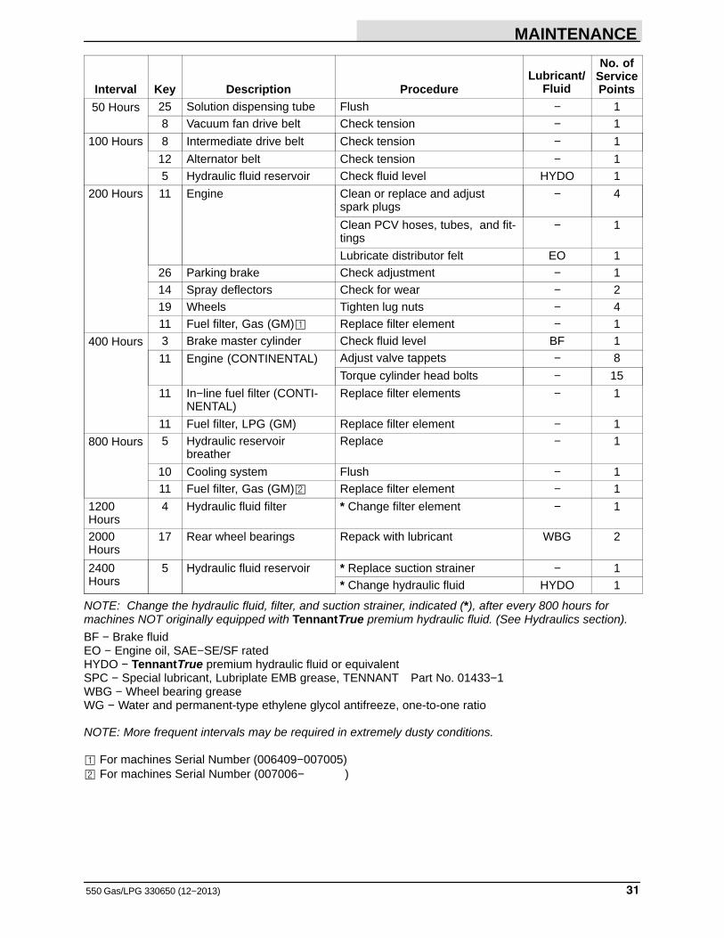
50 Hours 25 Solution dispensing tube Flush − 18 Vacuum fan drive belt Check tension − 1
100 Hours 8 Intermediate drive belt Check tension − 1
12 Alternator belt Check tension − 15 Hydraulic fluid reservoir Check fluid level HYDO 1
200 Hours 11 Engine Clean or replace and adjustspark plugs
− 4
Clean PCV hoses, tubes, and fit-tings
− 1
Lubricate distributor felt EO 126 Parking brake Check adjustment − 114 Spray deflectors Check for wear − 219 Wheels Tighten lug nuts − 411 Fuel filter, Gas (GM)� Replace filter element − 1
400 Hours 3 Brake master cylinder Check fluid level BF 1
11 Engine (CONTINENTAL) Adjust valve tappets − 8
Torque cylinder head bolts − 15
11 In−line fuel filter (CONTI-NENTAL)
Replace filter elements − 1
11 Fuel filter, LPG (GM) Replace filter element − 1
800 Hours 5 Hydraulic reservoirbreather
Replace − 1
10 Cooling system Flush − 111 Fuel filter, Gas (GM)� Replace filter element − 1
1200Hours
4 Hydraulic fluid filter * Change filter element − 1
2000Hours
17 Rear wheel bearings Repack with lubricant WBG 2
2400Hours
5 Hydraulic fluid reservoir * Replace suction strainer − 1* Change hydraulic fluid HYDO 1
NOTE: Change the hydraulic fluid, filter, and suction strainer, indicated (*), after every 800 hours formachines NOT originally equipped with TennantTrue premium hydraulic fluid. (See Hydraulics section).
BF − Brake fluidEO − Engine oil, SAE−SE/SF ratedHYDO − TennantTrue premium hydraulic fluid or equivalentSPC − Special lubricant, Lubriplate EMB grease, TENNANT Part No. 01433−1WBG − Wheel bearing greaseWG − Water and permanent-type ethylene glycol antifreeze, one-to-one ratio
NOTE: More frequent intervals may be required in extremely dusty conditions.
� For machines Serial Number (006409−007005)� For machines Serial Number (007006− )
MAINTENANCE
550 Gas/LPG 330650 (2−05)32
LUBRICATION
ENGINE
Check the engine oil level daily.
The engine should be lubricated with SAE−SE/SFrated engine oil. Change the engine oil and oilfilter after every 50 hours of operation. Changethe engine oil more frequently if the environmentis extremely dusty.
The following oil grades are recommended forengines operating in the ambient temperatureslisted.
MULTI−VISCOSITY OILS
Below 32�F
(Below 0�C)
5W 30
−10� to 90�F
(−23� to 32�C)
10W 30
−10� to above 90�F
(−23 to above 32�C)
10W 40
Above 10�F
(Above −12�C)
20W 40
The engine oil capacity of Continental Engines(machines below serial number 006409) is 7 qt(6.6 L) with filter.
The engine oil capacity of GM Engines (machinesserial number 006409 and above) is 5 qt (4.7 L)with filter. On GM engines, the oil fill is under thebreather cap.
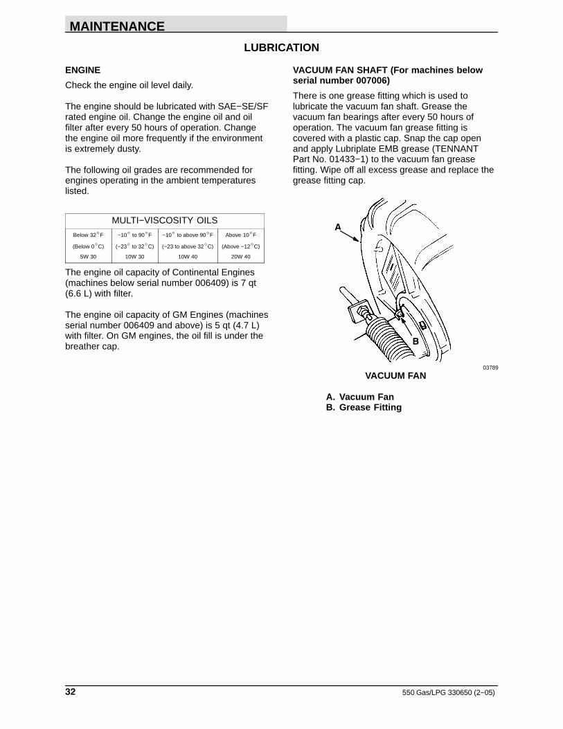
VACUUM FAN SHAFT (For machines belowserial number 007006)
There is one grease fitting which is used tolubricate the vacuum fan shaft. Grease thevacuum fan bearings after every 50 hours ofoperation. The vacuum fan grease fitting iscovered with a plastic cap. Snap the cap openand apply Lubriplate EMB grease (TENNANTPart No. 01433−1) to the vacuum fan greasefitting. Wipe off all excess grease and replace thegrease fitting cap.
B
A
03789
VACUUM FAN
A. Vacuum FanB. Grease Fitting
MAINTENANCE
33550 Gas/LPG 330650 (9−00)
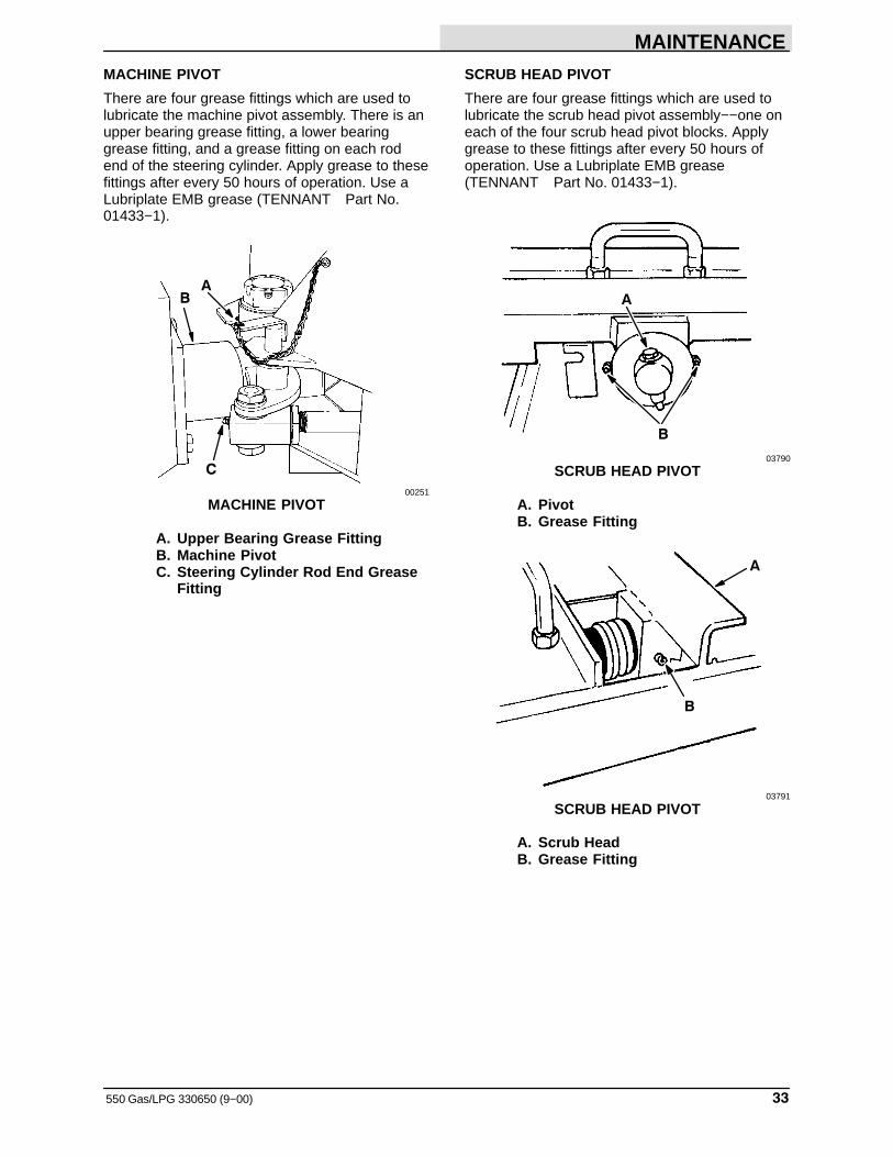
MACHINE PIVOT
There are four grease fittings which are used tolubricate the machine pivot assembly. There is anupper bearing grease fitting, a lower bearinggrease fitting, and a grease fitting on each rodend of the steering cylinder. Apply grease to thesefittings after every 50 hours of operation. Use aLubriplate EMB grease (TENNANT Part No.01433−1).
B
C
A
00251
MACHINE PIVOT
A. Upper Bearing Grease FittingB. Machine PivotC. Steering Cylinder Rod End Grease
Fitting
SCRUB HEAD PIVOT
There are four grease fittings which are used tolubricate the scrub head pivot assembly−−one oneach of the four scrub head pivot blocks. Applygrease to these fittings after every 50 hours ofoperation. Use a Lubriplate EMB grease(TENNANT Part No. 01433−1).
A
B
03790
SCRUB HEAD PIVOT
A. PivotB. Grease Fitting
A
B
03791
SCRUB HEAD PIVOT
A. Scrub HeadB. Grease Fitting
MAINTENANCE
550 Gas/LPG 330650 (9−00)34
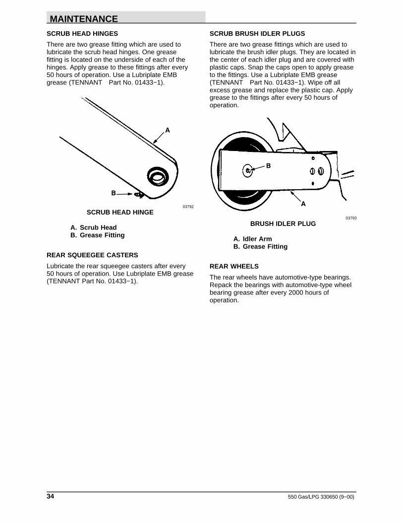
SCRUB HEAD HINGES
There are two grease fitting which are used tolubricate the scrub head hinges. One greasefitting is located on the underside of each of thehinges. Apply grease to these fittings after every50 hours of operation. Use a Lubriplate EMBgrease (TENNANT Part No. 01433−1).
B
A
03792
SCRUB HEAD HINGE
A. Scrub HeadB. Grease Fitting
REAR SQUEEGEE CASTERS
Lubricate the rear squeegee casters after every 50 hours of operation. Use Lubriplate EMB grease(TENNANT Part No. 01433−1).
SCRUB BRUSH IDLER PLUGS
There are two grease fittings which are used tolubricate the brush idler plugs. They are located inthe center of each idler plug and are covered withplastic caps. Snap the caps open to apply greaseto the fittings. Use a Lubriplate EMB grease(TENNANT Part No. 01433−1). Wipe off allexcess grease and replace the plastic cap. Applygrease to the fittings after every 50 hours ofoperation.
A
B
03793
BRUSH IDLER PLUG
A. Idler ArmB. Grease Fitting
REAR WHEELS
The rear wheels have automotive-type bearings.Repack the bearings with automotive-type wheelbearing grease after every 2000 hours ofoperation.
MAINTENANCE
35550 Gas/LPG 330650 (12−2013)
HYDRAULICS
HYDRAULIC FLUID
The quality and condition of the hydraulic fluidplays a very important role in how well themachine operates. TENNANT’s hydraulic fluid isdesigned to meet the special needs of itsmachines.
TENNANT’s hydraulic fluids provide longer life ofthe hydraulic components. There are three fluidsavailable for three different temperature ranges:
TennantTrue premium hydraulic fluid (Extended Life)
Partnumber
Ambienttemperature
ISOGrade
Ca-pacity
1057710 19� C (65� F) orhigher
100 3.8 L(1 gal)
1057711 19� C (65� F) orhigher
100 19 L (5 gal)
1069019 7 to 43� C (45 to 110� F)
68 3.8 L(1 gal)
1069020 7 to 43� C (45 to 110� F)
68 19 L (5 gal)
1057707 16� C (60� F) orlower
32 3.8 L(1 gal)
1057708 16� C (60� F) orlower
32 19 L (5 gal)
The higher temperature fluid is designed with ahigher viscosity and should not be used at thelower temperatures. Possible damage to thehydraulic pumps may occur because of improperlubrication.
The lower temperature fluid is a thinner fluiddesigned for colder temperatures.
If a locally-available hydraulic fluid is preferred, orif products of only one oil company are used,contact TENNANT Technical Customer Service tocheck the specifications of the substitute fluid.Using substitute fluids can cause prematurefailure of hydraulic components.
ATTENTION! Hydraulic componentsdepend on system hydraulic fluid forinternal lubrication. If dirt or othercontaminants are allowed to enter thehydraulic system, malfunctions,accelerated wear, and damage willresult.
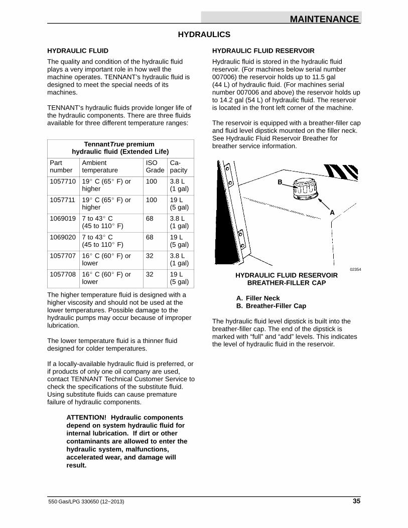
HYDRAULIC FLUID RESERVOIR
Hydraulic fluid is stored in the hydraulic fluidreservoir. (For machines below serial number007006) the reservoir holds up to 11.5 gal (44 L) of hydraulic fluid. (For machines serialnumber 007006 and above) the reservoir holds upto 14.2 gal (54 L) of hydraulic fluid. The reservoiris located in the front left corner of the machine.
The reservoir is equipped with a breather-filler capand fluid level dipstick mounted on the filler neck.See Hydraulic Fluid Reservoir Breather forbreather service information.
A
B
02354
HYDRAULIC FLUID RESERVOIRBREATHER-FILLER CAP
A. Filler NeckB. Breather-Filler Cap
The hydraulic fluid level dipstick is built into thebreather-filler cap. The end of the dipstick ismarked with “full” and “add” levels. This indicatesthe level of hydraulic fluid in the reservoir.
MAINTENANCE
550 Gas/LPG 330650 (10−10)36
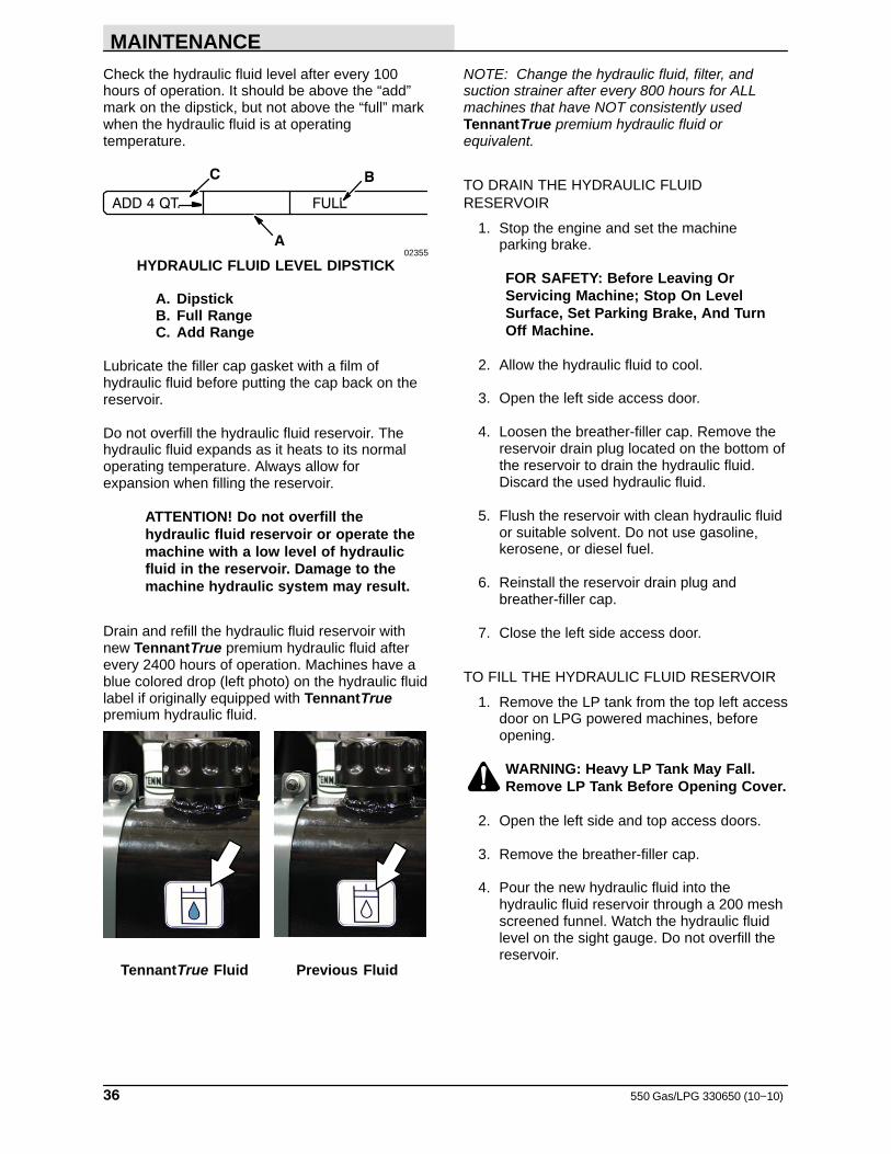
Check the hydraulic fluid level after every 100hours of operation. It should be above the “add”mark on the dipstick, but not above the “full” markwhen the hydraulic fluid is at operatingtemperature.
FULLADD 4 QT.
A
BC
02355
HYDRAULIC FLUID LEVEL DIPSTICK
A. DipstickB. Full RangeC. Add Range
Lubricate the filler cap gasket with a film ofhydraulic fluid before putting the cap back on thereservoir.
Do not overfill the hydraulic fluid reservoir. Thehydraulic fluid expands as it heats to its normaloperating temperature. Always allow forexpansion when filling the reservoir.
ATTENTION! Do not overfill thehydraulic fluid reservoir or operate themachine with a low level of hydraulicfluid in the reservoir. Damage to themachine hydraulic system may result.
Drain and refill the hydraulic fluid reservoir withnew TennantTrue premium hydraulic fluid afterevery 2400 hours of operation. Machines have ablue colored drop (left photo) on the hydraulic fluidlabel if originally equipped with TennantTruepremium hydraulic fluid.
TennantTrue Fluid Previous Fluid
NOTE: Change the hydraulic fluid, filter, andsuction strainer after every 800 hours for ALLmachines that have NOT consistently usedTennantTrue premium hydraulic fluid orequivalent.
TO DRAIN THE HYDRAULIC FLUIDRESERVOIR
1. Stop the engine and set the machineparking brake.
FOR SAFETY: Before Leaving OrServicing Machine; Stop On LevelSurface, Set Parking Brake, And TurnOff Machine.
2. Allow the hydraulic fluid to cool.
3. Open the left side access door.
4. Loosen the breather-filler cap. Remove thereservoir drain plug located on the bottom ofthe reservoir to drain the hydraulic fluid.Discard the used hydraulic fluid.
5. Flush the reservoir with clean hydraulic fluidor suitable solvent. Do not use gasoline,kerosene, or diesel fuel.
6. Reinstall the reservoir drain plug andbreather-filler cap.
7. Close the left side access door.
TO FILL THE HYDRAULIC FLUID RESERVOIR
1. Remove the LP tank from the top left accessdoor on LPG powered machines, beforeopening.
WARNING: Heavy LP Tank May Fall.Remove LP Tank Before Opening Cover.
2. Open the left side and top access doors.
3. Remove the breather-filler cap.
4. Pour the new hydraulic fluid into thehydraulic fluid reservoir through a 200 meshscreened funnel. Watch the hydraulic fluidlevel on the sight gauge. Do not overfill thereservoir.
MAINTENANCE
37550 Gas/LPG 330650 (10−10)
ATTENTION! Use only new-approvedhydraulic fluid to fill the hydraulic fluidreservoir.
5. Check the hydraulic fluid level in thereservoir with the reservoir dipstick.
6. Add hydraulic fluid until the level in thereservoir is between the “ADD” and the“FULL” range. Do not overfill.
NOTE: Do not overfill the hydraulic fluid reservoir.As hydraulic fluid heats to its normal operatingtemperature, it expands. Always allow for thisexpansion when filling the hydraulic fluid reservoir.
7. Place the reservoir breather-filler capsecurely on the reservoir.
8. Close the access doors.
9. Replace the LP tank on LPG poweredmachines.
The reservoir has a built-in strainer outlet thatfilters hydraulic fluid before it enters the system.Replace the strainer after every 2400 hours ofoperation.
HYDRAULIC FLUID RESERVOIR BREATHER
The hydraulic fluid reservoir is equipped with abreather. The breather is built into the filler cap ontop of the reservoir. It maintains atmosphericpressure in the reservoir. The breather should bereplaced after every 800 hours of operation.
HYDRAULIC FLUID FILTER
The hydraulic fluid filter is located in the enginecompartment. Replace the filter element afterevery 1200 hours of operation or if the cloggedhydraulic filter light remains on. Check thehydraulic fluid level and refill as needed.
TO REPLACE THE HYDRAULIC FLUID FILTERELEMENT
1. Park the machine on a flat surface, stop theengine, and set the machine parking brake.
FOR SAFETY: Before Leaving OrServicing Machine; Stop On LevelSurface, Set Parking Brake, And TurnOff Machine.
3. Open the left side access door.
4. Unthread and discard the hydraulic fluid filterelements.
NOTE: Discard all hydraulic fluid drained from thesystem. Drained hydraulic fluid may containforeign material harmful to the hydraulic system.
5. Apply a thin coat of hydraulic fluid to the sealof the new hydraulic fluid filter elements.
6. Thread and hand tighten the new hydraulicfluid filter elements on the filter heads.
7. Operate the machine and check for leaks.Correct any leaks found.
8. Check the hydraulic fluid reservoir level andfill as required.
9. Close the side access door.
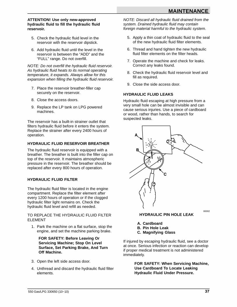
HYDRAULIC FLUID LEAKS
Hydraulic fluid escaping at high pressure from avery small hole can be almost invisible and cancause serious injuries. Use a piece of cardboardor wood, rather than hands, to search forsuspected leaks.
A
C
B
00002
HYDRAULIC PIN HOLE LEAK
A. CardboardB. Pin Hole LeakC. Magnifying Glass
If injured by escaping hydraulic fluid, see a doctorat once. Serious infection or reaction can developif proper medical treatment is not administeredimmediately.
FOR SAFETY: When Servicing Machine,Use Cardboard To Locate LeakingHydraulic Fluid Under Pressure.
MAINTENANCE
550 Gas/LPG 330650 (9−00)38
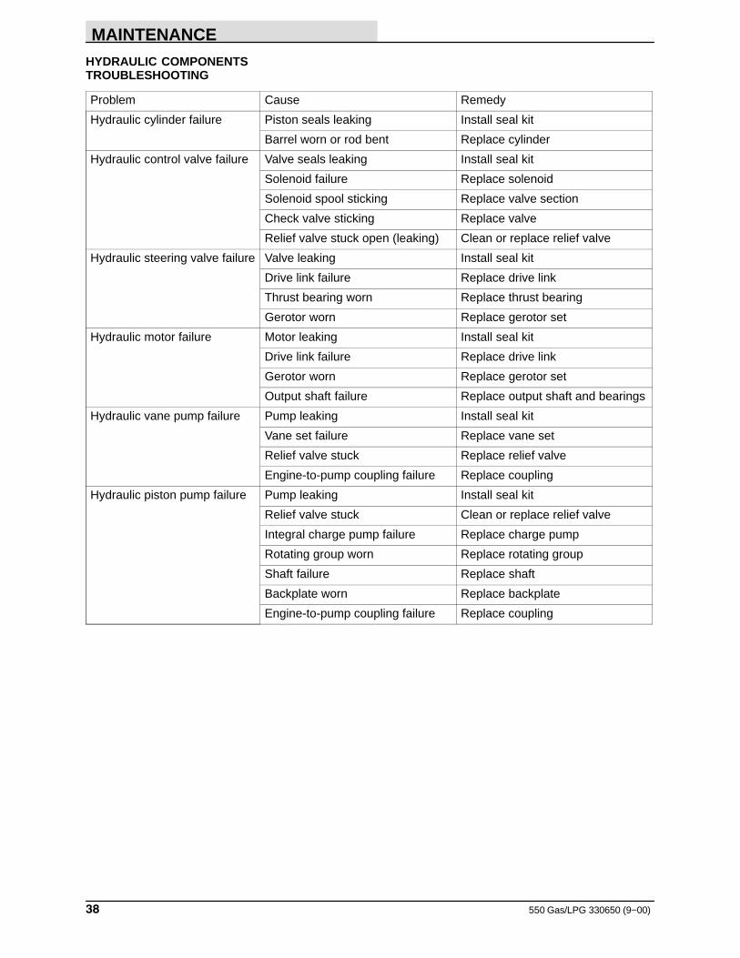
HYDRAULIC COMPONENTSTROUBLESHOOTING
Problem Cause Remedy
Hydraulic cylinder failure Piston seals leaking Install seal kit
Barrel worn or rod bent Replace cylinder
Hydraulic control valve failure Valve seals leaking Install seal kit
Solenoid failure Replace solenoid
Solenoid spool sticking Replace valve section
Check valve sticking Replace valve
Relief valve stuck open (leaking) Clean or replace relief valve
Hydraulic steering valve failure Valve leaking Install seal kit
Drive link failure Replace drive link
Thrust bearing worn Replace thrust bearing
Gerotor worn Replace gerotor set
Hydraulic motor failure Motor leaking Install seal kit
Drive link failure Replace drive link
Gerotor worn Replace gerotor set
Output shaft failure Replace output shaft and bearings
Hydraulic vane pump failure Pump leaking Install seal kit
Vane set failure Replace vane set
Relief valve stuck Replace relief valve
Engine-to-pump coupling failure Replace coupling
Hydraulic piston pump failure Pump leaking Install seal kit
Relief valve stuck Clean or replace relief valve
Integral charge pump failure Replace charge pump
Rotating group worn Replace rotating group
Shaft failure Replace shaft
Backplate worn Replace backplate
Engine-to-pump coupling failure Replace coupling
MAINTENANCE
39550 Gas/LPG 330650 (12−2013)
ENGINE
LUBRICATION
Check the engine oil level daily.
The engine should be lubricated with SAE−SE/SFrated engine oil. Change the engine oil and oilfilter after every 50 hours of operation. Changethe engine oil more frequently if the environmentis extremely dusty.
The following oil grades are recommended forengines operating in the ambient temperatureslisted.
MULTI−VISCOSITY OILS
Below 32�F
(Below 0�C)
5W 30
−10� to 90�F
(−23� to 32�C)
10W 30
−10� to above 90�F
(−23 to above 32�C)
10W 40
Above 10�F
(Above −12�C)
20W 40
The engine oil capacity − Continental Engines (for machines below serial number 006409) is 7 qt (6.6 L) with filter.
The engine oil capacity − GM Engines(for machines serial number 006409 and above) is 5 qt (4.7 L) with filter. On GM engines, the oil fillis under the breather cap.
COOLING SYSTEM
Maintaining cooling system efficiency is important.Engine temperatures must be brought up to andmaintained within the satisfactory range forefficient operation. However, the engine must bekept from overheating in order to prevent damageto the valves, pistons, and bearings.
Use soft, clean water mixed with permanent-type,ethylene glycol antifreeze in a one-to-one ratio.Deposits of sludge, scale, and rust prevent normalheat transfer. Flush the radiator and the coolingsystem after every 800 hours of operation using adependable cleaning compound. Follow themixing procedure recommended by the compoundmanufacturer. This is important because of thedifference in concentration and composition of thecleaning compounds. After cleaning, flush thesystem with clean water.
Whenever a cooling system is badly rust-cloggedas indicated by overflow loss or abnormally highoperating temperatures, corrective cleaning byreverse flow flushing will most effectively removethe heavy deposits of sludge, rust, and scale. Thereverse flow flushing should be performedimmediately after draining the cleaning solution.Flush the radiator first, then the engine, to allowthe engine to cool as much as possible.
Engine overheating may also be caused by dirtyradiator fins. The exterior fins of the radiator canbe cleaned with an air hose. Clean the radiatorexterior after every 50 hours of operation.
Blow all dust, which may have collected on theradiator, in through the grill and radiator fins,opposite the direction of normal air flow. Thisshould be done only after the radiator has cooled,to avoid cracking.
FOR SAFETY: When Servicing Machine,Wear Eye And Ear Protection WhenUsing Pressurized Air Or Water.
The engine is equipped with a 180� F (82� C)thermostat. Normal engine temperature is 200� F (93� C). Temperatures up to 220� F (104� C) are allowable. Temperatures over 220� F (104� C) indicate a problem exists.
NOTE: Overheating is always accompanied byloss of coolant water. If in doubt, check.
A pressure cap is used on the radiator to preventoverflow loss of water during normal operation.The spring-loaded valve in the cap closes theoutlet to the overflow pipe of the radiator and thusseals the system. Pressure developing within thesystem raises the boiling point of the coolant andallows higher temperatures without overflow lossfrom boiling. The pressure valve opens at 15 psi(100 kPa) allowing steam and water to pass outthe overflow pipe.
FOR SAFETY: When Servicing Machine,Avoid Contact With Hot Engine Coolant.
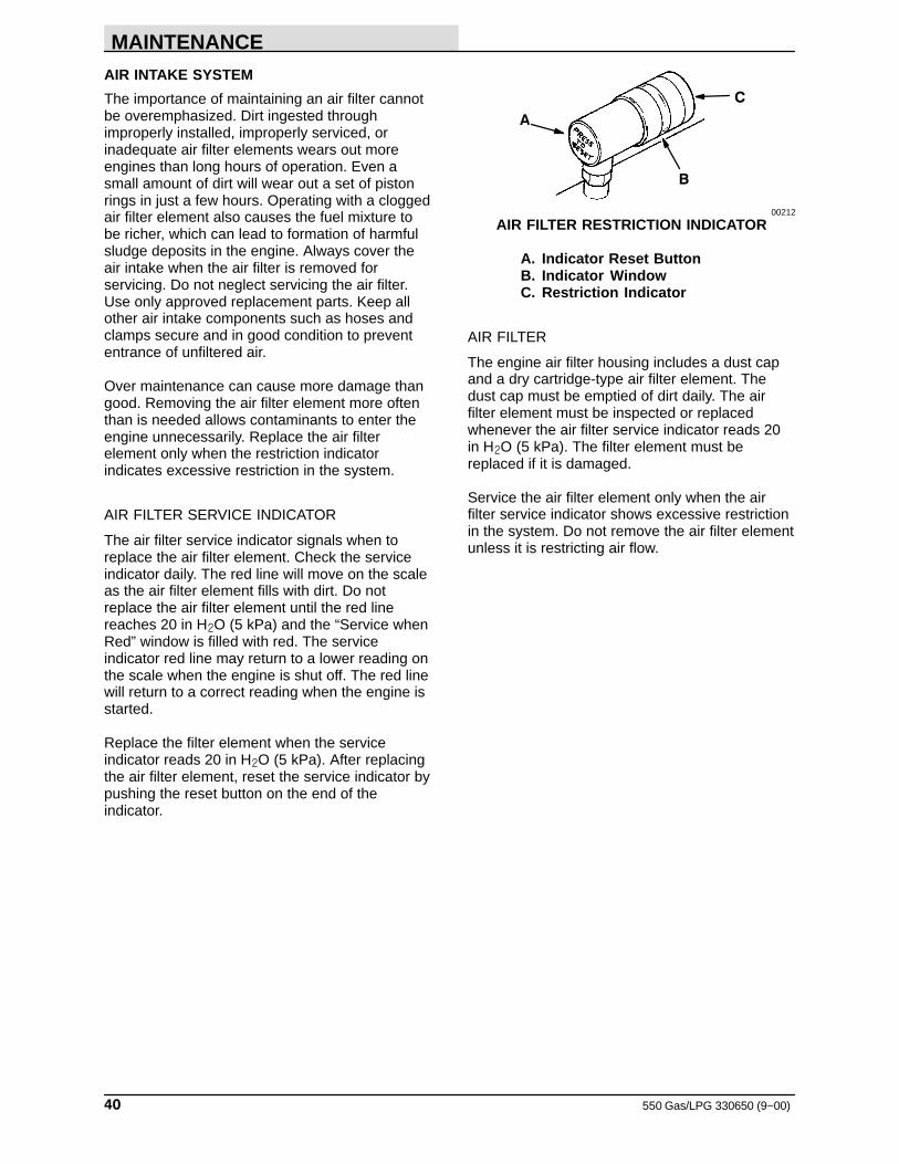
MAINTENANCE
550 Gas/LPG 330650 (9−00)40
AIR INTAKE SYSTEM
The importance of maintaining an air filter cannotbe overemphasized. Dirt ingested throughimproperly installed, improperly serviced, orinadequate air filter elements wears out moreengines than long hours of operation. Even asmall amount of dirt will wear out a set of pistonrings in just a few hours. Operating with a cloggedair filter element also causes the fuel mixture tobe richer, which can lead to formation of harmfulsludge deposits in the engine. Always cover theair intake when the air filter is removed forservicing. Do not neglect servicing the air filter.Use only approved replacement parts. Keep allother air intake components such as hoses andclamps secure and in good condition to prevententrance of unfiltered air.
Over maintenance can cause more damage thangood. Removing the air filter element more oftenthan is needed allows contaminants to enter theengine unnecessarily. Replace the air filterelement only when the restriction indicatorindicates excessive restriction in the system.
AIR FILTER SERVICE INDICATOR
The air filter service indicator signals when toreplace the air filter element. Check the serviceindicator daily. The red line will move on the scaleas the air filter element fills with dirt. Do notreplace the air filter element until the red linereaches 20 in H�O (5 kPa) and the “Service whenRed” window is filled with red. The serviceindicator red line may return to a lower reading onthe scale when the engine is shut off. The red linewill return to a correct reading when the engine isstarted.
Replace the filter element when the serviceindicator reads 20 in H�O (5 kPa). After replacingthe air filter element, reset the service indicator bypushing the reset button on the end of theindicator.
A
B
C
00212
AIR FILTER RESTRICTION INDICATOR
A. Indicator Reset ButtonB. Indicator WindowC. Restriction Indicator
AIR FILTER
The engine air filter housing includes a dust capand a dry cartridge-type air filter element. Thedust cap must be emptied of dirt daily. The airfilter element must be inspected or replacedwhenever the air filter service indicator reads 20in H�O (5 kPa). The filter element must bereplaced if it is damaged.
Service the air filter element only when the airfilter service indicator shows excessive restrictionin the system. Do not remove the air filter elementunless it is restricting air flow.
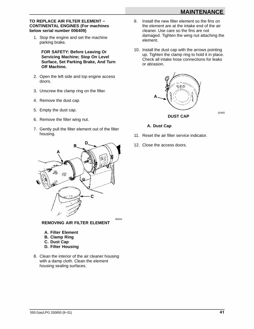
MAINTENANCE
41550 Gas/LPG 330650 (8−01)
TO REPLACE AIR FILTER ELEMENT −CONTINENTAL ENGINES (For machinesbelow serial number 006409)
1. Stop the engine and set the machineparking brake.
FOR SAFETY: Before Leaving OrServicing Machine; Stop On LevelSurface, Set Parking Brake, And TurnOff Machine.
2. Open the left side and top engine accessdoors.
3. Unscrew the clamp ring on the filter.
4. Remove the dust cap.
5. Empty the dust cap.
6. Remove the filter wing nut.
7. Gently pull the filter element out of the filterhousing.
B
C
A
D
00044
REMOVING AIR FILTER ELEMENT
A. Filter ElementB. Clamp RingC. Dust CapD. Filter Housing
8. Clean the interior of the air cleaner housingwith a damp cloth. Clean the elementhousing sealing surfaces.
9. Install the new filter element so the fins onthe element are at the intake end of the aircleaner. Use care so the fins are notdamaged. Tighten the wing nut attaching theelement.
10. Install the dust cap with the arrows pointingup. Tighten the clamp ring to hold it in place.Check all intake hose connections for leaksor abrasion.
A
02492
DUST CAP
A. Dust Cap
11. Reset the air filter service indicator.
12. Close the access doors.
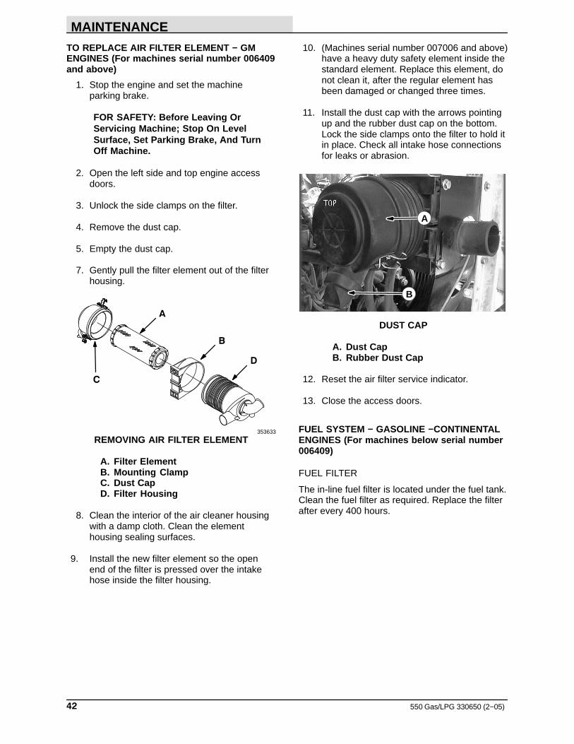
MAINTENANCE
550 Gas/LPG 330650 (2−05)42
TO REPLACE AIR FILTER ELEMENT − GMENGINES (For machines serial number 006409and above)
1. Stop the engine and set the machineparking brake.
FOR SAFETY: Before Leaving OrServicing Machine; Stop On LevelSurface, Set Parking Brake, And TurnOff Machine.
2. Open the left side and top engine accessdoors.
3. Unlock the side clamps on the filter.
4. Remove the dust cap.
5. Empty the dust cap.
7. Gently pull the filter element out of the filterhousing.
B
C
A
D
353633
REMOVING AIR FILTER ELEMENT
A. Filter ElementB. Mounting ClampC. Dust CapD. Filter Housing
8. Clean the interior of the air cleaner housingwith a damp cloth. Clean the elementhousing sealing surfaces.
9. Install the new filter element so the openend of the filter is pressed over the intakehose inside the filter housing.
10. (Machines serial number 007006 and above)have a heavy duty safety element inside thestandard element. Replace this element, donot clean it, after the regular element hasbeen damaged or changed three times.
11. Install the dust cap with the arrows pointingup and the rubber dust cap on the bottom.Lock the side clamps onto the filter to hold itin place. Check all intake hose connectionsfor leaks or abrasion.
A
B
DUST CAP
A. Dust CapB. Rubber Dust Cap
12. Reset the air filter service indicator.
13. Close the access doors.
FUEL SYSTEM − GASOLINE −CONTINENTALENGINES (For machines below serial number006409)
FUEL FILTER
The in-line fuel filter is located under the fuel tank.Clean the fuel filter as required. Replace the filterafter every 400 hours.
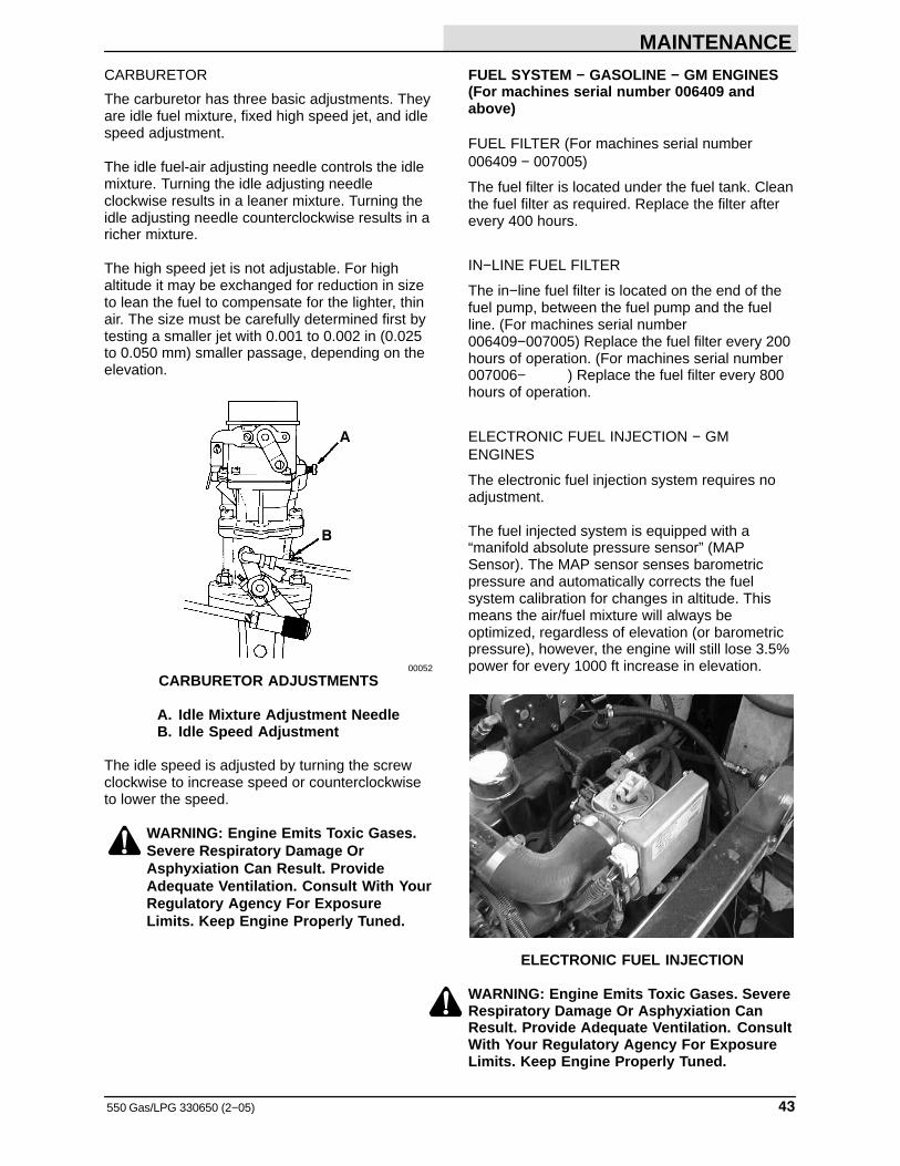
MAINTENANCE
43550 Gas/LPG 330650 (2−05)
CARBURETOR
The carburetor has three basic adjustments. Theyare idle fuel mixture, fixed high speed jet, and idlespeed adjustment.
The idle fuel-air adjusting needle controls the idlemixture. Turning the idle adjusting needleclockwise results in a leaner mixture. Turning theidle adjusting needle counterclockwise results in aricher mixture.
The high speed jet is not adjustable. For highaltitude it may be exchanged for reduction in sizeto lean the fuel to compensate for the lighter, thinair. The size must be carefully determined first bytesting a smaller jet with 0.001 to 0.002 in (0.025to 0.050 mm) smaller passage, depending on theelevation.
A
B
00052
CARBURETOR ADJUSTMENTS
A. Idle Mixture Adjustment NeedleB. Idle Speed Adjustment
The idle speed is adjusted by turning the screwclockwise to increase speed or counterclockwiseto lower the speed.
WARNING: Engine Emits Toxic Gases.Severe Respiratory Damage OrAsphyxiation Can Result. ProvideAdequate Ventilation. Consult With YourRegulatory Agency For ExposureLimits. Keep Engine Properly Tuned.
FUEL SYSTEM − GASOLINE − GM ENGINES(For machines serial number 006409 andabove)
FUEL FILTER (For machines serial number006409 − 007005)
The fuel filter is located under the fuel tank. Cleanthe fuel filter as required. Replace the filter afterevery 400 hours.
IN−LINE FUEL FILTER
The in−line fuel filter is located on the end of thefuel pump, between the fuel pump and the fuelline. (For machines serial number006409−007005) Replace the fuel filter every 200hours of operation. (For machines serial number007006− ) Replace the fuel filter every 800hours of operation.
ELECTRONIC FUEL INJECTION − GMENGINES
The electronic fuel injection system requires noadjustment.
The fuel injected system is equipped with a“manifold absolute pressure sensor” (MAPSensor). The MAP sensor senses barometricpressure and automatically corrects the fuelsystem calibration for changes in altitude. Thismeans the air/fuel mixture will always beoptimized, regardless of elevation (or barometricpressure), however, the engine will still lose 3.5%power for every 1000 ft increase in elevation.
A
ELECTRONIC FUEL INJECTION
WARNING: Engine Emits Toxic Gases. SevereRespiratory Damage Or Asphyxiation CanResult. Provide Adequate Ventilation. ConsultWith Your Regulatory Agency For ExposureLimits. Keep Engine Properly Tuned.
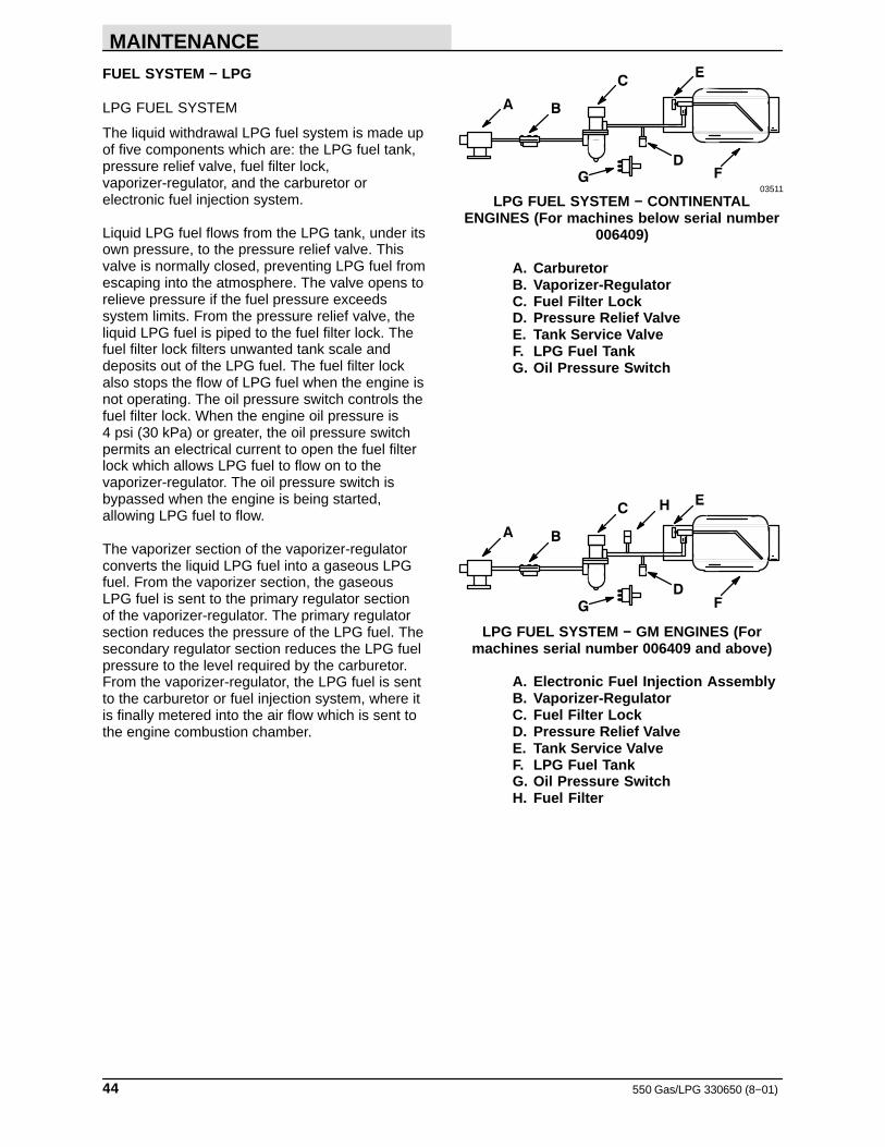
MAINTENANCE
550 Gas/LPG 330650 (8−01)44
FUEL SYSTEM − LPG
LPG FUEL SYSTEM
The liquid withdrawal LPG fuel system is made upof five components which are: the LPG fuel tank,pressure relief valve, fuel filter lock,vaporizer-regulator, and the carburetor orelectronic fuel injection system.
Liquid LPG fuel flows from the LPG tank, under itsown pressure, to the pressure relief valve. Thisvalve is normally closed, preventing LPG fuel fromescaping into the atmosphere. The valve opens torelieve pressure if the fuel pressure exceedssystem limits. From the pressure relief valve, theliquid LPG fuel is piped to the fuel filter lock. Thefuel filter lock filters unwanted tank scale anddeposits out of the LPG fuel. The fuel filter lockalso stops the flow of LPG fuel when the engine isnot operating. The oil pressure switch controls thefuel filter lock. When the engine oil pressure is 4 psi (30 kPa) or greater, the oil pressure switchpermits an electrical current to open the fuel filterlock which allows LPG fuel to flow on to thevaporizer-regulator. The oil pressure switch isbypassed when the engine is being started,allowing LPG fuel to flow.
The vaporizer section of the vaporizer-regulatorconverts the liquid LPG fuel into a gaseous LPGfuel. From the vaporizer section, the gaseousLPG fuel is sent to the primary regulator sectionof the vaporizer-regulator. The primary regulatorsection reduces the pressure of the LPG fuel. Thesecondary regulator section reduces the LPG fuelpressure to the level required by the carburetor.From the vaporizer-regulator, the LPG fuel is sentto the carburetor or fuel injection system, where itis finally metered into the air flow which is sent tothe engine combustion chamber.
A B
C
D
E
FG03511
LPG FUEL SYSTEM − CONTINENTALENGINES (For machines below serial number
006409)
A. CarburetorB. Vaporizer-RegulatorC. Fuel Filter LockD. Pressure Relief ValveE. Tank Service ValveF. LPG Fuel TankG. Oil Pressure Switch
A B
C
D
E
FG
H
LPG FUEL SYSTEM − GM ENGINES (Formachines serial number 006409 and above)
A. Electronic Fuel Injection AssemblyB. Vaporizer-RegulatorC. Fuel Filter LockD. Pressure Relief ValveE. Tank Service ValveF. LPG Fuel TankG. Oil Pressure SwitchH. Fuel Filter
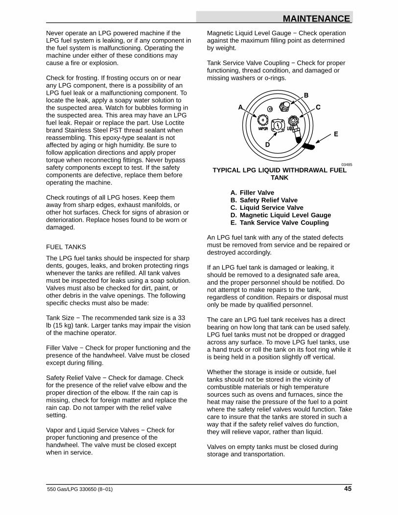
MAINTENANCE
45550 Gas/LPG 330650 (8−01)
Never operate an LPG powered machine if theLPG fuel system is leaking, or if any component inthe fuel system is malfunctioning. Operating themachine under either of these conditions maycause a fire or explosion.
Check for frosting. If frosting occurs on or nearany LPG component, there is a possibility of anLPG fuel leak or a malfunctioning component. Tolocate the leak, apply a soapy water solution tothe suspected area. Watch for bubbles forming inthe suspected area. This area may have an LPGfuel leak. Repair or replace the part. Use Loctitebrand Stainless Steel PST thread sealant whenreassembling. This epoxy-type sealant is notaffected by aging or high humidity. Be sure tofollow application directions and apply propertorque when reconnecting fittings. Never bypasssafety components except to test. If the safetycomponents are defective, replace them beforeoperating the machine.
Check routings of all LPG hoses. Keep themaway from sharp edges, exhaust manifolds, orother hot surfaces. Check for signs of abrasion ordeterioration. Replace hoses found to be worn ordamaged.
FUEL TANKS
The LPG fuel tanks should be inspected for sharpdents, gouges, leaks, and broken protecting ringswhenever the tanks are refilled. All tank valvesmust be inspected for leaks using a soap solution.Valves must also be checked for dirt, paint, orother debris in the valve openings. The followingspecific checks must also be made:
Tank Size − The recommended tank size is a 33lb (15 kg) tank. Larger tanks may impair the visionof the machine operator.
Filler Valve − Check for proper functioning and thepresence of the handwheel. Valve must be closedexcept during filling.
Safety Relief Valve − Check for damage. Checkfor the presence of the relief valve elbow and theproper direction of the elbow. If the rain cap ismissing, check for foreign matter and replace therain cap. Do not tamper with the relief valvesetting.
Vapor and Liquid Service Valves − Check forproper functioning and presence of thehandwheel. The valve must be closed exceptwhen in service.
Magnetic Liquid Level Gauge − Check operationagainst the maximum filling point as determinedby weight.
Tank Service Valve Coupling − Check for properfunctioning, thread condition, and damaged ormissing washers or o-rings.
D
CA
B
E
03485
TYPICAL LPG LIQUID WITHDRAWAL FUELTANK
A. Filler ValveB. Safety Relief ValveC. Liquid Service ValveD. Magnetic Liquid Level GaugeE. Tank Service Valve Coupling
An LPG fuel tank with any of the stated defectsmust be removed from service and be repaired ordestroyed accordingly.
If an LPG fuel tank is damaged or leaking, itshould be removed to a designated safe area,and the proper personnel should be notified. Donot attempt to make repairs to the tank,regardless of condition. Repairs or disposal mustonly be made by qualified personnel.
The care an LPG fuel tank receives has a directbearing on how long that tank can be used safely.LPG fuel tanks must not be dropped or draggedacross any surface. To move LPG fuel tanks, usea hand truck or roll the tank on its foot ring while itis being held in a position slightly off vertical.
Whether the storage is inside or outside, fueltanks should not be stored in the vicinity ofcombustible materials or high temperaturesources such as ovens and furnaces, since theheat may raise the pressure of the fuel to a pointwhere the safety relief valves would function. Takecare to insure that the tanks are stored in such away that if the safety relief valves do function,they will relieve vapor, rather than liquid.
Valves on empty tanks must be closed duringstorage and transportation.
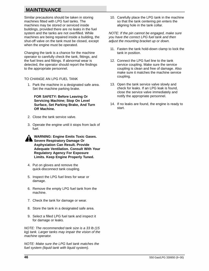
MAINTENANCE
550 Gas/LPG 330650 (9−00)46
Similar precautions should be taken in storingmachines fitted with LPG fuel tanks. Themachines may be stored or serviced insidebuildings, provided there are no leaks in the fuelsystem and the tanks are not overfilled. Whilemachines are being repaired inside a building, theshut-off valve on the tank must be closed, exceptwhen the engine must be operated.
Changing the tank is a chance for the machineoperator to carefully check the tank, fittings, andthe fuel lines and fittings. If abnormal wear isdetected, the operator should report the findingsto the appropriate personnel.
TO CHANGE AN LPG FUEL TANK
1. Park the machine in a designated safe area.Set the machine parking brake.
FOR SAFETY: Before Leaving OrServicing Machine; Stop On LevelSurface, Set Parking Brake, And TurnOff Machine.
2. Close the tank service valve.
3. Operate the engine until it stops from lack offuel.
WARNING: Engine Emits Toxic Gases.Severe Respiratory Damage OrAsphyxiation Can Result. ProvideAdequate Ventilation. Consult With YourRegulatory Agency For ExposureLimits. Keep Engine Properly Tuned.
4. Put on gloves and remove thequick-disconnect tank coupling.
5. Inspect the LPG fuel lines for wear ordamage.
6. Remove the empty LPG fuel tank from themachine.
7. Check the tank for damage or wear.
8. Store the tank in a designated safe area.
9. Select a filled LPG fuel tank and inspect itfor damage or leaks.
NOTE: The recommended tank size is a 33 lb (15kg) tank. Larger tanks may impair the vision of themachine operator.
NOTE: Make sure the LPG fuel tank matches thefuel system (liquid tank with liquid system).
10. Carefully place the LPG tank in the machineso that the tank centering pin enters thealigning hole in the tank collar.
NOTE: If the pin cannot be engaged, make sureyou have the correct LPG fuel tank and thenadjust the mounting bracket up or down.
11. Fasten the tank hold-down clamp to lock thetank in position.
12. Connect the LPG fuel line to the tankservice coupling. Make sure the servicecoupling is clean and free of damage. Alsomake sure it matches the machine servicecoupling.
13. Open the tank service valve slowly andcheck for leaks. If an LPG leak is found,close the service valve immediately andnotify the appropriate personnel.
14. If no leaks are found, the engine is ready tostart.
MAINTENANCE
47550 Gas/LPG 330650 (2−06)
FUEL FILTER LOCK
The fuel filter lock filters the LPG fuel. The fuelfilter lock also stops the flow of LPG fuel to theengine when the engine is not operating, or whenthe engine oil pressure is less than 4 psi (30 kPa).
Replace the fuel filter lock filter pack with the filterpack replacement kit every 400 hours or ifdiminished gas flow indicates the filter is clogged.A drain plug is provided for purging the filter bowl.Clean out the bowl when replacing the filter pack.
VAPORIZER-REGULATOR
If any malfunction is noted, completelydisassemble the vaporizer-regulator. Clean all ofthe parts in alcohol. Inspect all of the parts andreplace where needed. Carefully reassemble thevaporizer-regulator with the seal repair kit. Checkfor proper operation.
CARBURETOR − CONTINENTAL ENGINES (Formachines below serial number 006409)
If any malfunction is noted, completelydisassemble the carburetor. Clean all of the partsin alcohol.
Inspect all of the parts and replace when needed.Carefully reassemble the carburetor with the sealrepair kit.
ELECTRONIC FUEL INJECTION SYSTEM − GMENGINES (For machines serial number 006409and above)
The electronic fuel injection system requires noregular maintenance. If any malfunction is notedcontact TENNANT service personel.
OIL PRESSURE SWITCH
The engine oil pressure switch requires no regularmaintenance. Never bypass the oil pressureswitch as this is a safety feature which preventsLPG fuel from flowing when the engine is notoperating properly.
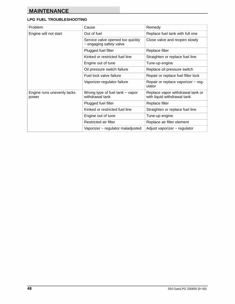
MAINTENANCE
550 Gas/LPG 330650 (9−00)48
LPG FUEL TROUBLESHOOTING
Problem Cause Remedy
Engine will not start Out of fuel Replace fuel tank with full one
Service valve opened too quickly− engaging safety valve
Close valve and reopen slowly
Plugged fuel filter Replace filter
Kinked or restricted fuel line Straighten or replace fuel line
Engine out of tune Tune-up engine
Oil pressure switch failure Replace oil pressure switch
Fuel lock valve failure Repair or replace fuel filter lock
Vaporizer-regulator failure Repair or replace vaporizer − reg-ulator
Engine runs unevenly lackspower
Wrong type of fuel tank − vaporwithdrawal tank
Replace vapor withdrawal tank orwith liquid withdrawal tank
Plugged fuel filter Replace filter
Kinked or restricted fuel line Straighten or replace fuel line
Engine out of tune Tune-up engine
Restricted air filter Replace air filter element
Vaporizer − regulator maladjusted Adjust vaporizer − regulator
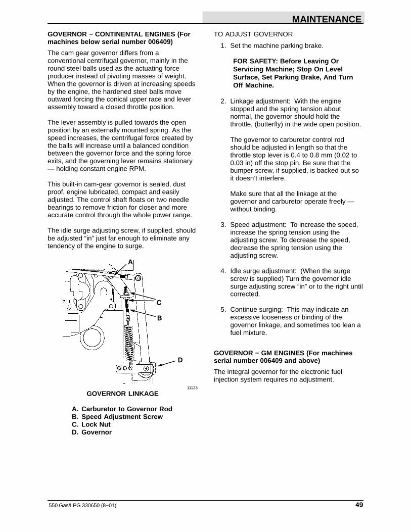
MAINTENANCE
49550 Gas/LPG 330650 (8−01)
GOVERNOR − CONTINENTAL ENGINES (Formachines below serial number 006409)
The cam gear governor differs from aconventional centrifugal governor, mainly in theround steel balls used as the actuating forceproducer instead of pivoting masses of weight.When the governor is driven at increasing speedsby the engine, the hardened steel balls moveoutward forcing the conical upper race and leverassembly toward a closed throttle position.
The lever assembly is pulled towards the openposition by an externally mounted spring. As thespeed increases, the centrifugal force created bythe balls will increase until a balanced conditionbetween the governor force and the spring forceexits, and the governing lever remains stationary— holding constant engine RPM.
This built-in cam-gear governor is sealed, dustproof, engine lubricated, compact and easilyadjusted. The control shaft floats on two needlebearings to remove friction for closer and moreaccurate control through the whole power range.
The idle surge adjusting screw, if supplied, shouldbe adjusted “in” just far enough to eliminate anytendency of the engine to surge.
A
B
C
D
11123
GOVERNOR LINKAGE
A. Carburetor to Governor RodB. Speed Adjustment ScrewC. Lock NutD. Governor
TO ADJUST GOVERNOR
1. Set the machine parking brake.
FOR SAFETY: Before Leaving OrServicing Machine; Stop On LevelSurface, Set Parking Brake, And TurnOff Machine.
2. Linkage adjustment: With the enginestopped and the spring tension aboutnormal, the governor should hold thethrottle, (butterfly) in the wide open position.
The governor to carburetor control rodshould be adjusted in length so that thethrottle stop lever is 0.4 to 0.8 mm (0.02 to0.03 in) off the stop pin. Be sure that thebumper screw, if supplied, is backed out soit doesn’t interfere.
Make sure that all the linkage at thegovernor and carburetor operate freely —without binding.
3. Speed adjustment: To increase the speed,increase the spring tension using theadjusting screw. To decrease the speed,decrease the spring tension using theadjusting screw.
4. Idle surge adjustment: (When the surgescrew is supplied) Turn the governor idlesurge adjusting screw “in” or to the right untilcorrected.
5. Continue surging: This may indicate anexcessive looseness or binding of thegovernor linkage, and sometimes too lean afuel mixture.
GOVERNOR − GM ENGINES (For machinesserial number 006409 and above)
The integral governor for the electronic fuelinjection system requires no adjustment.
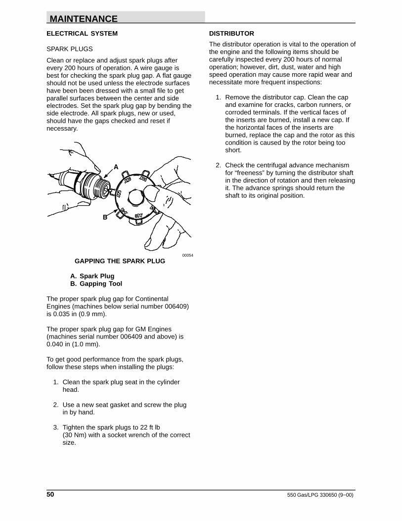
MAINTENANCE
550 Gas/LPG 330650 (9−00)50
ELECTRICAL SYSTEM
SPARK PLUGS
Clean or replace and adjust spark plugs afterevery 200 hours of operation. A wire gauge isbest for checking the spark plug gap. A flat gaugeshould not be used unless the electrode surfaceshave been been dressed with a small file to getparallel surfaces between the center and sideelectrodes. Set the spark plug gap by bending theside electrode. All spark plugs, new or used,should have the gaps checked and reset ifnecessary.
A
B
00054
GAPPING THE SPARK PLUG
A. Spark PlugB. Gapping Tool
The proper spark plug gap for ContinentalEngines (machines below serial number 006409)is 0.035 in (0.9 mm).
The proper spark plug gap for GM Engines(machines serial number 006409 and above) is0.040 in (1.0 mm).
To get good performance from the spark plugs,follow these steps when installing the plugs:
1. Clean the spark plug seat in the cylinderhead.
2. Use a new seat gasket and screw the plugin by hand.
3. Tighten the spark plugs to 22 ft lb (30 Nm) with a socket wrench of the correctsize.
DISTRIBUTOR
The distributor operation is vital to the operation ofthe engine and the following items should becarefully inspected every 200 hours of normaloperation; however, dirt, dust, water and highspeed operation may cause more rapid wear andnecessitate more frequent inspections:
1. Remove the distributor cap. Clean the capand examine for cracks, carbon runners, orcorroded terminals. If the vertical faces ofthe inserts are burned, install a new cap. Ifthe horizontal faces of the inserts areburned, replace the cap and the rotor as thiscondition is caused by the rotor being tooshort.
2. Check the centrifugal advance mechanismfor “freeness” by turning the distributor shaftin the direction of rotation and then releasingit. The advance springs should return theshaft to its original position.
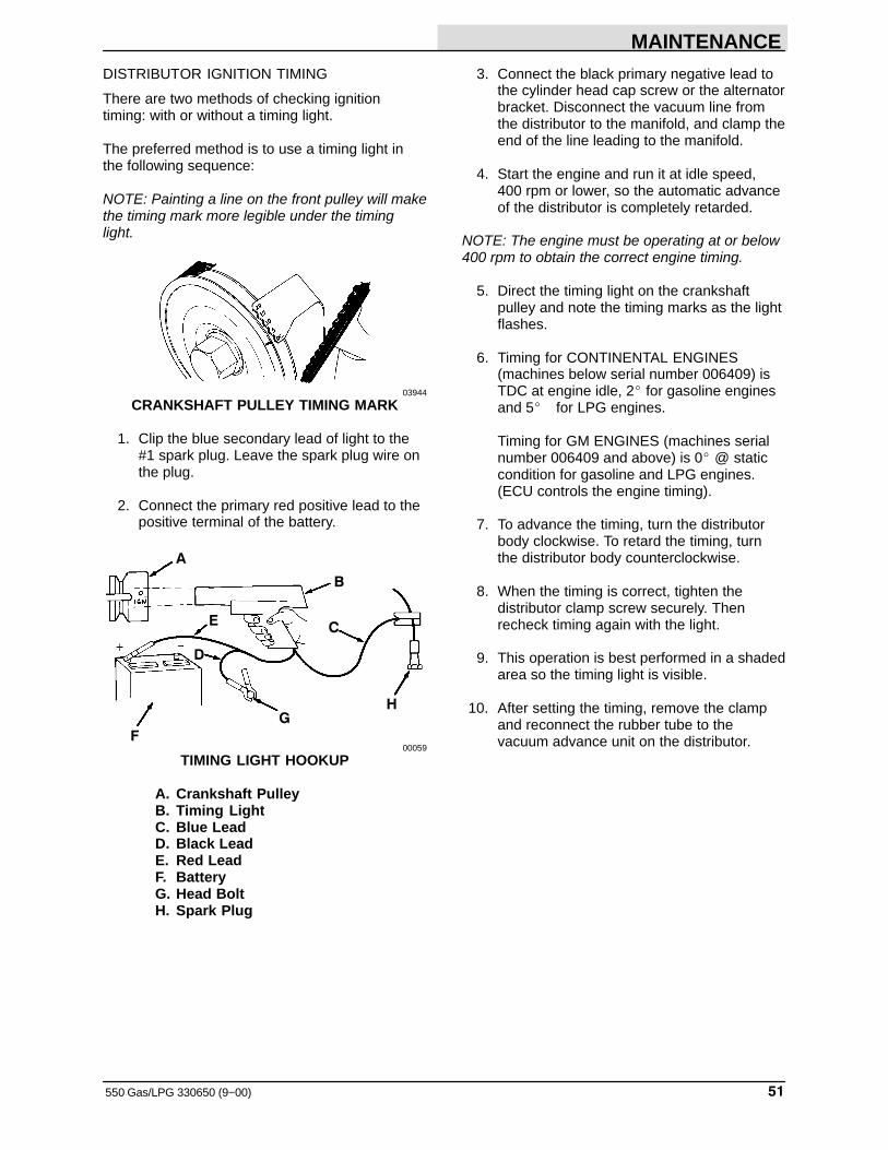
MAINTENANCE
51550 Gas/LPG 330650 (9−00)
DISTRIBUTOR IGNITION TIMING
There are two methods of checking ignitiontiming: with or without a timing light.
The preferred method is to use a timing light inthe following sequence:
NOTE: Painting a line on the front pulley will makethe timing mark more legible under the timinglight.
03944
CRANKSHAFT PULLEY TIMING MARK
1. Clip the blue secondary lead of light to the#1 spark plug. Leave the spark plug wire onthe plug.
2. Connect the primary red positive lead to thepositive terminal of the battery.
A
B
C
D
E
F
GH
00059
TIMING LIGHT HOOKUP
A. Crankshaft PulleyB. Timing LightC. Blue LeadD. Black LeadE. Red LeadF. BatteryG. Head BoltH. Spark Plug
3. Connect the black primary negative lead tothe cylinder head cap screw or the alternatorbracket. Disconnect the vacuum line fromthe distributor to the manifold, and clamp theend of the line leading to the manifold.
4. Start the engine and run it at idle speed, 400 rpm or lower, so the automatic advanceof the distributor is completely retarded.
NOTE: The engine must be operating at or below400 rpm to obtain the correct engine timing.
5. Direct the timing light on the crankshaftpulley and note the timing marks as the lightflashes.
6. Timing for CONTINENTAL ENGINES(machines below serial number 006409) isTDC at engine idle, 2� for gasoline enginesand 5� for LPG engines.
Timing for GM ENGINES (machines serialnumber 006409 and above) is 0� @ staticcondition for gasoline and LPG engines.(ECU controls the engine timing).
7. To advance the timing, turn the distributorbody clockwise. To retard the timing, turnthe distributor body counterclockwise.
8. When the timing is correct, tighten thedistributor clamp screw securely. Thenrecheck timing again with the light.
9. This operation is best performed in a shadedarea so the timing light is visible.
10. After setting the timing, remove the clampand reconnect the rubber tube to thevacuum advance unit on the distributor.
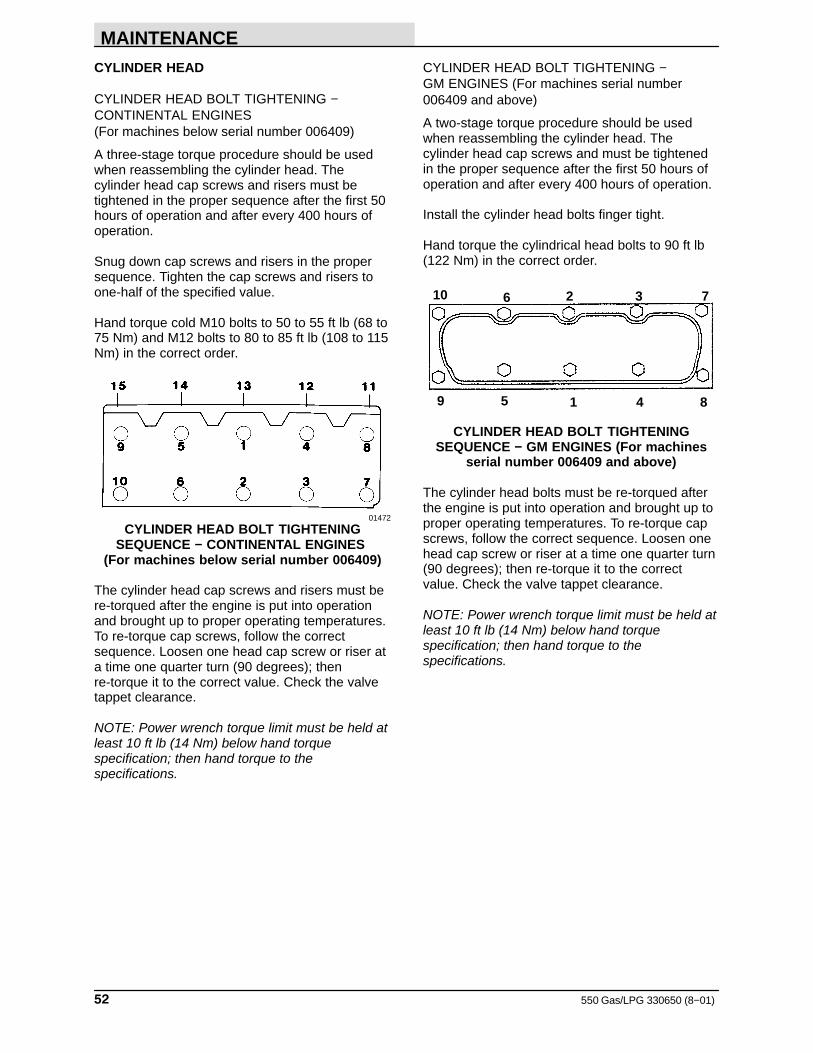
MAINTENANCE
550 Gas/LPG 330650 (8−01)52
CYLINDER HEAD
CYLINDER HEAD BOLT TIGHTENING −CONTINENTAL ENGINES (For machines below serial number 006409)
A three-stage torque procedure should be usedwhen reassembling the cylinder head. Thecylinder head cap screws and risers must betightened in the proper sequence after the first 50hours of operation and after every 400 hours ofoperation.
Snug down cap screws and risers in the propersequence. Tighten the cap screws and risers toone-half of the specified value.
Hand torque cold M10 bolts to 50 to 55 ft lb (68 to75 Nm) and M12 bolts to 80 to 85 ft lb (108 to 115Nm) in the correct order.
01472
CYLINDER HEAD BOLT TIGHTENINGSEQUENCE − CONTINENTAL ENGINES
(For machines below serial number 006409)
The cylinder head cap screws and risers must bere-torqued after the engine is put into operationand brought up to proper operating temperatures.To re-torque cap screws, follow the correctsequence. Loosen one head cap screw or riser ata time one quarter turn (90 degrees); thenre-torque it to the correct value. Check the valvetappet clearance.
NOTE: Power wrench torque limit must be held atleast 10 ft lb (14 Nm) below hand torquespecification; then hand torque to thespecifications.
CYLINDER HEAD BOLT TIGHTENING − GM ENGINES (For machines serial number006409 and above)
A two-stage torque procedure should be usedwhen reassembling the cylinder head. Thecylinder head cap screws and must be tightenedin the proper sequence after the first 50 hours ofoperation and after every 400 hours of operation.
Install the cylinder head bolts finger tight.
Hand torque the cylindrical head bolts to 90 ft lb(122 Nm) in the correct order.
10 6 2 3 7
9 5 1 4 8
CYLINDER HEAD BOLT TIGHTENINGSEQUENCE − GM ENGINES (For machines
serial number 006409 and above)
The cylinder head bolts must be re-torqued afterthe engine is put into operation and brought up toproper operating temperatures. To re-torque capscrews, follow the correct sequence. Loosen onehead cap screw or riser at a time one quarter turn(90 degrees); then re-torque it to the correctvalue. Check the valve tappet clearance.
NOTE: Power wrench torque limit must be held atleast 10 ft lb (14 Nm) below hand torquespecification; then hand torque to thespecifications.
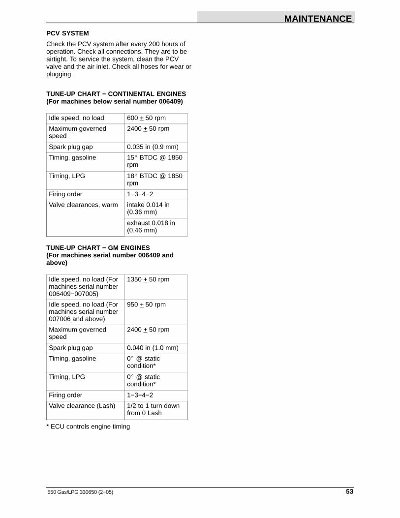
MAINTENANCE
53550 Gas/LPG 330650 (2−05)
PCV SYSTEM
Check the PCV system after every 200 hours ofoperation. Check all connections. They are to beairtight. To service the system, clean the PCVvalve and the air inlet. Check all hoses for wear orplugging.
TUNE-UP CHART − CONTINENTAL ENGINES(For machines below serial number 006409)
Idle speed, no load 600 + 50 rpm
Maximum governedspeed
2400 + 50 rpm
Spark plug gap 0.035 in (0.9 mm)
Timing, gasoline 15� BTDC @ 1850rpm
Timing, LPG 18� BTDC @ 1850rpm
Firing order 1−3−4−2
Valve clearances, warm intake 0.014 in(0.36 mm)
exhaust 0.018 in(0.46 mm)
TUNE-UP CHART − GM ENGINES(For machines serial number 006409 andabove)
Idle speed, no load (Formachines serial number006409−007005)
1350 + 50 rpm
Idle speed, no load (Formachines serial number007006 and above)
950 + 50 rpm
Maximum governedspeed
2400 + 50 rpm
Spark plug gap 0.040 in (1.0 mm)
Timing, gasoline 0� @ static condition*
Timing, LPG 0� @ static condition*
Firing order 1−3−4−2
Valve clearance (Lash) 1/2 to 1 turn downfrom 0 Lash
* ECU controls engine timing
MAINTENANCE
550 Gas/LPG 330650 (9−00)54
ELECTRICAL SYSTEM
BATTERY
The battery is rated at 12 V, 540 ccA. The batteryis located in the engine compartment. Whenremoving battery cables, remove the negative (−)cable before the positive (+) cable.
Do not allow the battery to remain in dischargedcondition for any length of time. Do not operatethe machine if the battery is in poor condition oronly 25% of the charge is left.
Clean the top surface and the terminals of thebattery periodically. Use a strong solution ofbaking soda and water. Brush the solutionsparingly over the battery top, terminals, andcable clamps. Do not allow any baking sodasolution to enter the battery. Use a wire brush toclean the terminal posts and the cableconnectors. After cleaning, apply a coating ofclear petroleum jelly to the terminals and thecable connectors. Keep the top of the batteryclean and dry.
Keep all metallic objects off the top of the battery,as they may cause a short circuit. Replace wornor damaged wires.
The electrolyte level in regular non−sealedbatteries can be checked. The level must alwaysbe above the battery plates. Add distilled water tomaintain solution at the correct level above theplates, but do not overfill. Never add acid tobatteries, only water. Keep vent plugs firmly inplace at all times, except when adding water ortaking hydrometer readings.
FOR SAFETY: When Servicing Machine,Avoid Contact With Battery Acid.
If, when checking battery specific gravity, one ormore battery cells tests lower than the otherbattery cells (0.050 or more), the cell is damaged,shorted, or is about to fail.
NOTE: Do not take readings immediately afteradding water − if the water and acid are notthoroughly mixed, the readings may not beaccurate. Check the hydrometer readings againstthis chart:
SPECIFIC GRAVITY
at 80� F (27� C)
BATTERY
CONDITION
1.260 − 1.280 100% charged
1.230 − 1.250 75% charged
1.200 − 1.220 50% charged
1.170 − 1.190 25% charged
1.110 − 1.160 Discharged
NOTE: If the readings are taken when the batteryelectrolyte is any temperature other than 80� F(27� C), the reading must be temperaturecorrected.
To determine the corrected specific gravityreading when the temperature of the batteryelectrolyte is other than 80� F (27� C):
Add to the specific gravity reading 0.004, 4points, for each 10� F (5.5� C) above 80� F (27� C).
Subtract from the specific gravity reading0.004, 4 points, for each 10� F (5.5� C)below 80� F (27� C).
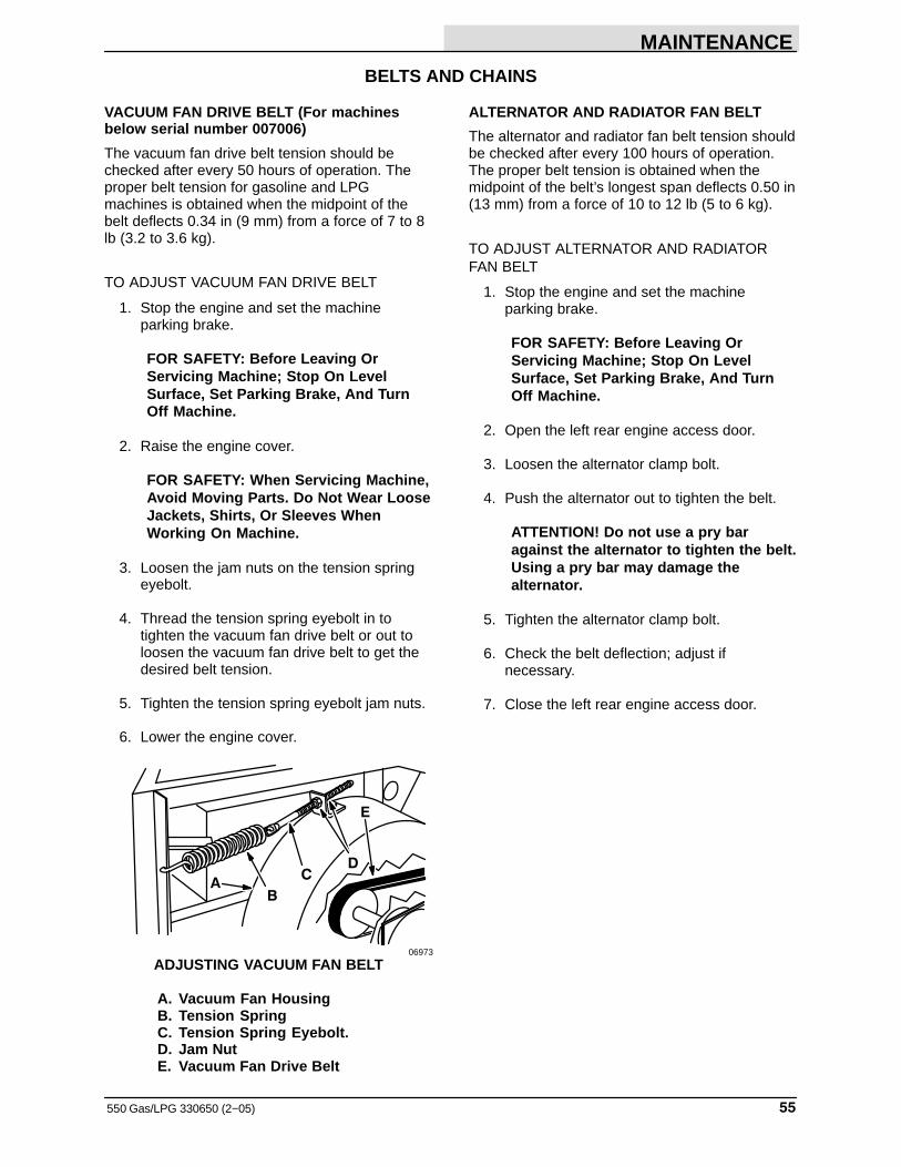
MAINTENANCE
55550 Gas/LPG 330650 (2−05)
BELTS AND CHAINS
VACUUM FAN DRIVE BELT (For machinesbelow serial number 007006)
The vacuum fan drive belt tension should bechecked after every 50 hours of operation. Theproper belt tension for gasoline and LPGmachines is obtained when the midpoint of thebelt deflects 0.34 in (9 mm) from a force of 7 to 8lb (3.2 to 3.6 kg).
TO ADJUST VACUUM FAN DRIVE BELT
1. Stop the engine and set the machineparking brake.
FOR SAFETY: Before Leaving OrServicing Machine; Stop On LevelSurface, Set Parking Brake, And TurnOff Machine.
2. Raise the engine cover.
FOR SAFETY: When Servicing Machine,Avoid Moving Parts. Do Not Wear LooseJackets, Shirts, Or Sleeves WhenWorking On Machine.
3. Loosen the jam nuts on the tension springeyebolt.
4. Thread the tension spring eyebolt in totighten the vacuum fan drive belt or out toloosen the vacuum fan drive belt to get thedesired belt tension.
5. Tighten the tension spring eyebolt jam nuts.
6. Lower the engine cover.
AB
CD
E
06973
ADJUSTING VACUUM FAN BELT
A. Vacuum Fan HousingB. Tension SpringC. Tension Spring Eyebolt.D. Jam NutE. Vacuum Fan Drive Belt
ALTERNATOR AND RADIATOR FAN BELT
The alternator and radiator fan belt tension shouldbe checked after every 100 hours of operation.The proper belt tension is obtained when themidpoint of the belt’s longest span deflects 0.50 in(13 mm) from a force of 10 to 12 lb (5 to 6 kg).
TO ADJUST ALTERNATOR AND RADIATORFAN BELT
1. Stop the engine and set the machineparking brake.
FOR SAFETY: Before Leaving OrServicing Machine; Stop On LevelSurface, Set Parking Brake, And TurnOff Machine.
2. Open the left rear engine access door.
3. Loosen the alternator clamp bolt.
4. Push the alternator out to tighten the belt.
ATTENTION! Do not use a pry baragainst the alternator to tighten the belt.Using a pry bar may damage thealternator.
5. Tighten the alternator clamp bolt.
6. Check the belt deflection; adjust ifnecessary.
7. Close the left rear engine access door.
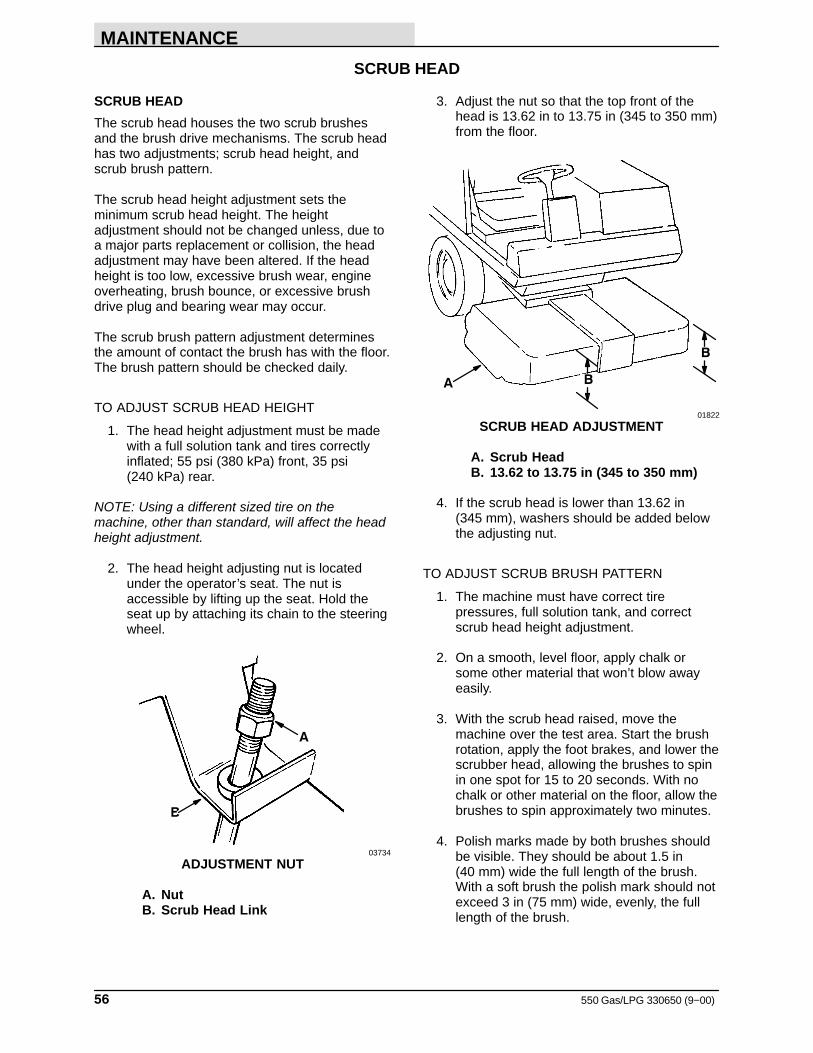
MAINTENANCE
550 Gas/LPG 330650 (9−00)56
SCRUB HEAD
SCRUB HEAD
The scrub head houses the two scrub brushesand the brush drive mechanisms. The scrub headhas two adjustments; scrub head height, andscrub brush pattern.
The scrub head height adjustment sets theminimum scrub head height. The heightadjustment should not be changed unless, due toa major parts replacement or collision, the headadjustment may have been altered. If the headheight is too low, excessive brush wear, engineoverheating, brush bounce, or excessive brushdrive plug and bearing wear may occur.
The scrub brush pattern adjustment determinesthe amount of contact the brush has with the floor.The brush pattern should be checked daily.
TO ADJUST SCRUB HEAD HEIGHT
1. The head height adjustment must be madewith a full solution tank and tires correctlyinflated; 55 psi (380 kPa) front, 35 psi (240 kPa) rear.
NOTE: Using a different sized tire on themachine, other than standard, will affect the headheight adjustment.
2. The head height adjusting nut is locatedunder the operator’s seat. The nut isaccessible by lifting up the seat. Hold theseat up by attaching its chain to the steeringwheel.
B
A
03734
ADJUSTMENT NUT
A. NutB. Scrub Head Link
3. Adjust the nut so that the top front of thehead is 13.62 in to 13.75 in (345 to 350 mm)from the floor.
A
B
B
01822
SCRUB HEAD ADJUSTMENT
A. Scrub HeadB. 13.62 to 13.75 in (345 to 350 mm)
4. If the scrub head is lower than 13.62 in (345 mm), washers should be added belowthe adjusting nut.
TO ADJUST SCRUB BRUSH PATTERN
1. The machine must have correct tirepressures, full solution tank, and correctscrub head height adjustment.
2. On a smooth, level floor, apply chalk orsome other material that won’t blow awayeasily.
3. With the scrub head raised, move themachine over the test area. Start the brushrotation, apply the foot brakes, and lower thescrubber head, allowing the brushes to spinin one spot for 15 to 20 seconds. With nochalk or other material on the floor, allow thebrushes to spin approximately two minutes.
4. Polish marks made by both brushes shouldbe visible. They should be about 1.5 in (40 mm) wide the full length of the brush.With a soft brush the polish mark should notexceed 3 in (75 mm) wide, evenly, the fulllength of the brush.
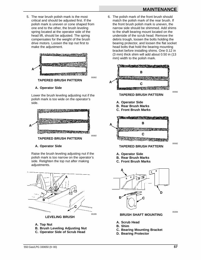
MAINTENANCE
57550 Gas/LPG 330650 (9−00)
5. The rear brush polish mark is the mostcritical and should be adjusted first. If thepolish mark is uneven or cone shaped fromone end to the other, the brush levelingspring located at the operator side of thehead lift, should be adjusted. The springcompensates for the weight of the brushdrive motors. Loosen the top nut first tomake the adjustment.
A
00082
TAPERED BRUSH PATTERN
A. Operator Side
Lower the brush leveling adjusting nut if thepolish mark is too wide on the operator’sside.
A
00082
TAPERED BRUSH PATTERN
A. Operator Side
Raise the brush leveling adjusting nut if thepolish mark is too narrow on the operator’sside. Retighten the top nut after makingadjustments.
B
C
A
00285
LEVELING BRUSH
A. Top NutB. Brush Leveling Adjusting NutC. Operator Side of Scrub Head
6. The polish mark of the front brush shouldmatch the polish mark of the rear brush. Ifthe front brush polish mark is uneven, thenarrow side should be shimmed. Add shimsto the shaft bearing mount located on theunderside of the scrub head. Remove thedebris trough, loosen the bolts holding thebearing protector, and loosen the flat sockethead bolts that hold the bearing mountingbracket before installing shims. One 0.12 in(3 mm) thick shim will add about 0.50 in (13mm) width to the polish mark.
B
AC
00082
TAPERED BRUSH PATTERN
A. Operator SideB. Rear Brush MarksC. Front Brush Marks
B
C
A
00082
TAPERED BRUSH PATTERN
A. Operator SideB. Rear Brush MarksC. Front Brush Marks
A
D
CB
00284
BRUSH SHAFT MOUNTING
A. Scrub HeadB. ShimC. Bearing Mounting BracketD. Bearing Protector
MAINTENANCE
550 Gas/LPG 330650 (9−00)58
7. Recheck the brush polish marks to see if thefront and rear match, and are even acrossthe full length of the brush.
8. The width of the rear brush polish mark canvary more than the desired 2 to 3 in (50 to75 mm). There are adjusting knobs locatedon the drive side of the scrub head. Turn theknob clockwise to decrease the width of thepolish mark and counterclockwise toincrease the width of the polish mark. Thepolish mark should not exceed 3 in (75 mm).Use the locking strips to keep the adjustingknobs in place.
A
BC
00286
BRUSH ADJUSTMENT KNOBS
A. Locking StripsB. Front Brush Adjusting KnobC. Rear Brush Adjusting Knob
9. For maximum brush life, rotate the brushesfrom front-to-rear after every 50 hours ofoperation.
SCRUB BRUSHES
The scrub brushes are tubular and run the widthof the scrub head sweeping debris into the debristrough while they scrub the floor. The brushesshould be inspected daily for damage or wear.Remove any string or wire found tangled on thescrub brushes, drive or idler hubs.
Rotate the scrub brushes from front-to-rear afterevery 50 hours of operation for maximum brushlife and best scrubbing performance.
The scrub brush patterns should be checkeddaily. The width of the patterns should be 2 to 3 in(50 to 75 mm). The scrub brush pattern isadjusted by turning the adjustment knobs on topof the scrub head. See TO ADJUST SCRUBBRUSH PATTERN.
TO REPLACE SCRUB BRUSHES
1. Raise scrub head and set scrub head lock.
WARNING: Raised Scrub Head May Fall.Block Scrub Head Up.
2. Stop engine and set parking brake.
FOR SAFETY: Before Leaving OrServicing Machine; Stop On LevelSurface, Set Parking Brake, And TurnOff Machine.
3. Open right side door on scrub head and usethe chain to hold the door in the raisedposition.
4. Use wrench to remove hex head boltattaching the brush arm.
NOTE: If arm does not come off easily, insert boltin the adjacent threaded hole and screw in untilarm comes off.
5. The brush arm and brush can then be pulledout.
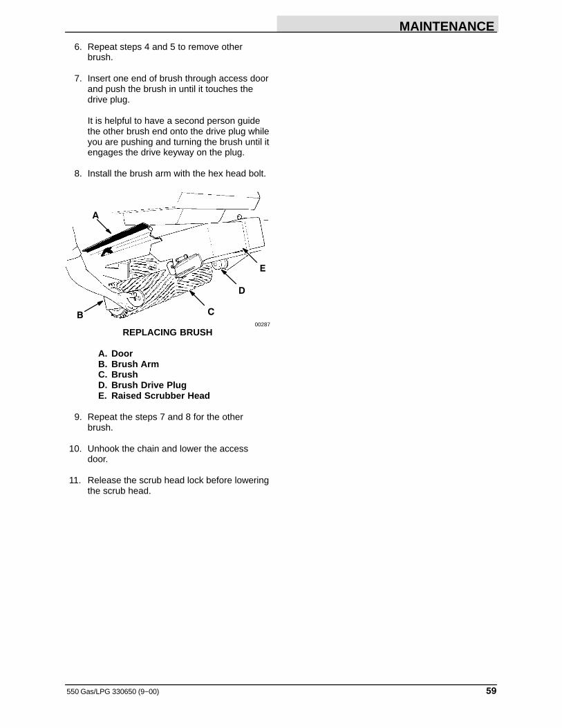
MAINTENANCE
59550 Gas/LPG 330650 (9−00)
6. Repeat steps 4 and 5 to remove otherbrush.
7. Insert one end of brush through access doorand push the brush in until it touches thedrive plug.
It is helpful to have a second person guidethe other brush end onto the drive plug whileyou are pushing and turning the brush until itengages the drive keyway on the plug.
8. Install the brush arm with the hex head bolt.
E
D
C
A
B00287
REPLACING BRUSH
A. DoorB. Brush ArmC. BrushD. Brush Drive PlugE. Raised Scrubber Head
9. Repeat the steps 7 and 8 for the otherbrush.
10. Unhook the chain and lower the accessdoor.
11. Release the scrub head lock before loweringthe scrub head.
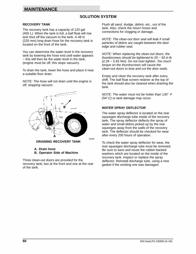
MAINTENANCE
550 Gas/LPG 330650 (9−00)60
SOLUTION SYSTEM
RECOVERY TANK
The recovery tank has a capacity of 120 gal (455 L). When the tank is full, a ball float will riseand shut off the vacuum to the tank. A 48 in (220 mm) long drain hose for the recovery tank islocated on the front of the tank.
You can determine the water level in the recoverytank by lowering the hose end until water appears− this will then be the water level in the tank,(engine must be off; this stops vacuum).
To drain the tank, lower the hose and place it neara suitable floor drain.
NOTE: The hose will not drain until the engine isoff, stopping vacuum.
A
B
00288
DRAINING RECOVERY TANK
A. Drain hoseB. Operator Side of Machine
Three clean-out doors are provided for therecovery tank; two at the front and one at the rearof the tank.
Flush all sand, sludge, debris, etc., out of thetank. Also, check the return hoses andconnections for clogging or damage.
NOTE: The clean-out door seal will leak if smallparticles of debris are caught between the dooredge and rubber seal.
NOTE: When replacing the clean-out doors, thethumbscrews should be tightened to 20 − 50 in lb(2.26 − 5.65 Nm). Do not over-tighten. Too muchtorque on the thumbscrews will cause theclean-out doors to bow and cut the door seals.
Empty and clean the recovery tank after everyshift. The ball float screen retainer at the top ofthe tank should also be cleaned when draining thetank.
NOTE: The water must not be hotter than 130� F (54�C) or tank damage may occur.
WATER SPRAY DEFLECTOR
The water spray deflector is located on the rearsqueegee discharge tube inside of the recoverytank. The spray deflector deflects the spray ofwater and small debris picked up by the rearsqueegee away from the walls of the recoverytank. The deflector should be checked for wearafter every 200 hours of operation.
To check the water spray deflector for wear, therear squeegee discharge tube must be removed.Be sure to save and reuse the rubber-backedwashers which are located on the inside of therecovery tank. Inspect or replace the spraydeflector. Reinstall discharge tube, using a newgasket if the existing one was damaged.
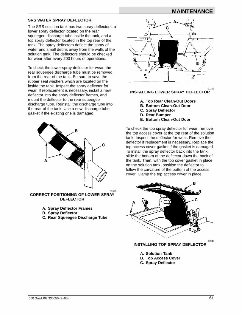
MAINTENANCE
61550 Gas/LPG 330650 (9−00)
SRS WATER SPRAY DEFLECTOR
The SRS solution tank has two spray deflectors; alower spray deflector located on the rearsqueegee discharge tube inside the tank, and atop spray deflector located in the top rear of thetank. The spray deflectors deflect the spray ofwater and small debris away from the walls of thesolution tank. The deflectors should be checkedfor wear after every 200 hours of operations.
To check the lower spray deflector for wear, therear squeegee discharge tube must be removedfrom the rear of the tank. Be sure to save therubber seal washers which are located on theinside the tank. Inspect the spray deflector forwear. If replacement is necessary, install a newdeflector into the spray deflector frames, andmount the deflector to the rear squeegeedischarge tube. Reinstall the discharge tube intothe rear of the tank. Use a new discharge tubegasket if the existing one is damaged.
A
C
B
00339
CORRECT POSITIONING OF LOWER SPRAYDEFLECTOR
A. Spray Deflector FramesB. Spray DeflectorC. Rear Squeegee Discharge Tube
A
C
EB D
00353
INSTALLING LOWER SPRAY DEFLECTOR
A. Top Rear Clean-Out DoorsB. Bottom Clean-Out DoorC. Spray DeflectorD. Rear BumperE. Bottom Clean-Out Door
To check the top spray deflector for wear, removethe top access cover at the top rear of the solutiontank. Inspect the deflector for wear. Remove thedeflector if replacement is necessary. Replace thetop access cover gasket if the gasket is damaged.To install the spray deflector back into the tank,slide the bottom of the deflector down the back ofthe tank. Then, with the top cover gasket in placeon the solution tank, position the deflector tofollow the curvature of the bottom of the accesscover. Clamp the top access cover in place.
AC
B
00346
INSTALLING TOP SPRAY DEFLECTOR
A. Solution TankB. Top Access CoverC. Spray Deflector
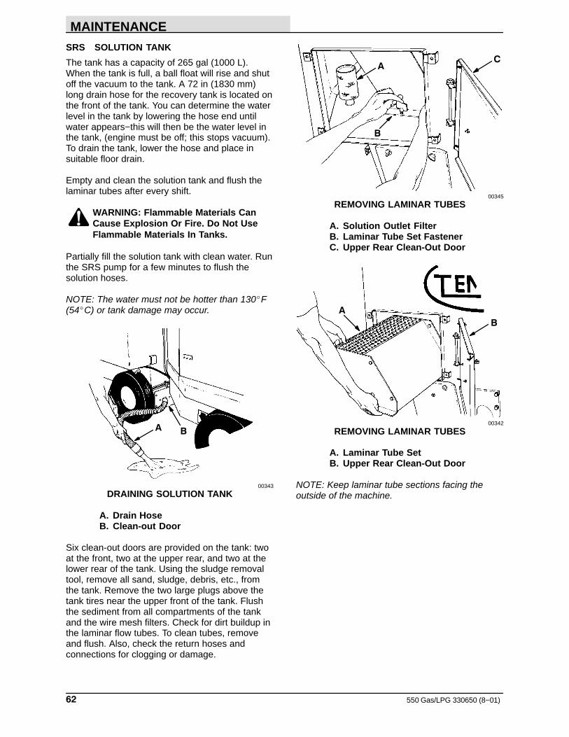
MAINTENANCE
550 Gas/LPG 330650 (8−01)62
SRS SOLUTION TANK
The tank has a capacity of 265 gal (1000 L).When the tank is full, a ball float will rise and shutoff the vacuum to the tank. A 72 in (1830 mm)long drain hose for the recovery tank is located onthe front of the tank. You can determine the waterlevel in the tank by lowering the hose end untilwater appears−this will then be the water level inthe tank, (engine must be off; this stops vacuum).To drain the tank, lower the hose and place insuitable floor drain.
Empty and clean the solution tank and flush thelaminar tubes after every shift.
WARNING: Flammable Materials CanCause Explosion Or Fire. Do Not UseFlammable Materials In Tanks.
Partially fill the solution tank with clean water. Runthe SRS pump for a few minutes to flush thesolution hoses.
NOTE: The water must not be hotter than 130�F(54�C) or tank damage may occur.
BA
00343
DRAINING SOLUTION TANK
A. Drain HoseB. Clean-out Door
Six clean-out doors are provided on the tank: twoat the front, two at the upper rear, and two at thelower rear of the tank. Using the sludge removaltool, remove all sand, sludge, debris, etc., fromthe tank. Remove the two large plugs above thetank tires near the upper front of the tank. Flushthe sediment from all compartments of the tankand the wire mesh filters. Check for dirt buildup inthe laminar flow tubes. To clean tubes, removeand flush. Also, check the return hoses andconnections for clogging or damage.
AC
B
00345
REMOVING LAMINAR TUBES
A. Solution Outlet FilterB. Laminar Tube Set FastenerC. Upper Rear Clean-Out Door
A
B
00342
REMOVING LAMINAR TUBES
A. Laminar Tube SetB. Upper Rear Clean-Out Door
NOTE: Keep laminar tube sections facing theoutside of the machine.
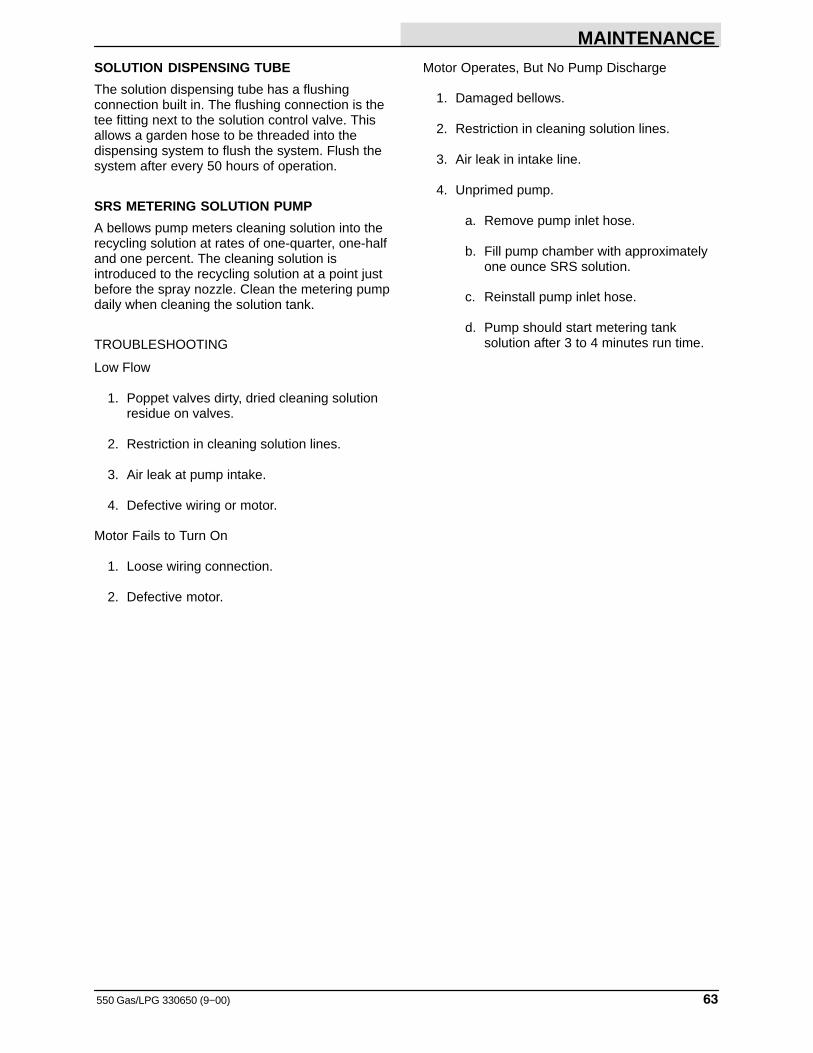
MAINTENANCE
63550 Gas/LPG 330650 (9−00)
SOLUTION DISPENSING TUBE
The solution dispensing tube has a flushingconnection built in. The flushing connection is thetee fitting next to the solution control valve. Thisallows a garden hose to be threaded into thedispensing system to flush the system. Flush thesystem after every 50 hours of operation.
SRS METERING SOLUTION PUMP
A bellows pump meters cleaning solution into therecycling solution at rates of one-quarter, one-halfand one percent. The cleaning solution isintroduced to the recycling solution at a point justbefore the spray nozzle. Clean the metering pumpdaily when cleaning the solution tank.
TROUBLESHOOTING
Low Flow
1. Poppet valves dirty, dried cleaning solutionresidue on valves.
2. Restriction in cleaning solution lines.
3. Air leak at pump intake.
4. Defective wiring or motor.
Motor Fails to Turn On
1. Loose wiring connection.
2. Defective motor.
Motor Operates, But No Pump Discharge
1. Damaged bellows.
2. Restriction in cleaning solution lines.
3. Air leak in intake line.
4. Unprimed pump.
a. Remove pump inlet hose.
b. Fill pump chamber with approximatelyone ounce SRS solution.
c. Reinstall pump inlet hose.
d. Pump should start metering tanksolution after 3 to 4 minutes run time.
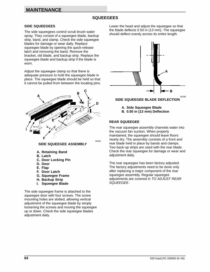
MAINTENANCE
550 Gas/LPG 330650 (9−00)64
SQUEEGEES
SIDE SQUEEGEES
The side squeegees control scrub brush waterspray. They consist of a squeegee blade, backupstrip, band, and clamp. Check the side squeegeeblades for damage or wear daily. Replacesqueegee blade by opening the quick-releaselatch and removing the band. Remove thebracket, old blade, and backup strip. Replace thesqueegee blade and backup strip if the blade isworn.
Adjust the squeegee clamp so that there isadequate pressure to hold the squeegee blade inplace. The squeegee blade should be held so thatit cannot be pulled from between the locating pins.
D
A
C
I H
E
F
G
B
00302
SIDE SQUEEGEE ASSEMBLY
A. Retaining BandB. LatchC. Door Locking PinD. DoorE. FlapF. Door LatchG. Squeegee FrameH. Backup StripI. Squeegee Blade
The side squeegee frame is attached to thesqueegee door with four screws. The screwmounting holes are slotted, allowing verticaladjustment of the squeegee blade by simplyloosening the screws and moving the squeegeeup or down. Check the side squeegee bladesadjustment daily.
Lower the head and adjust the squeegee so thatthe blade deflects 0.50 in (13 mm). The squeegeeshould deflect evenly across its entire length.
A
B
00289
SIDE SQUEEGEE BLADE DEFLECTION
A. Side Squeegee BladeB. 0.50 in (13 mm) Deflection
REAR SQUEEGEE
The rear squeegee assembly channels water intothe vacuum fan suction. When properlymaintained, the squeegee should leave floorsnearly dry. The assembly consists of a front andrear blade held in place by bands and clamps.Two back-up strips are used with the rear blade.Check the rear squeegee for damage or wear andadjustment daily.
The rear squeegee has been factory adjusted.The factory adjustments need to be done onlyafter replacing a major component of the rearsqueegee assembly. Regular squeegeeadjustments are covered in TO ADJUST REARSQUEEGEE.
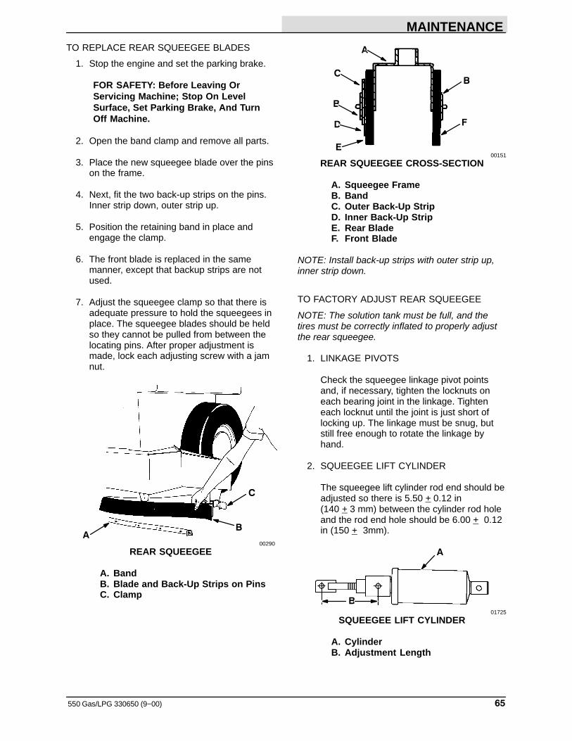
MAINTENANCE
65550 Gas/LPG 330650 (9−00)
TO REPLACE REAR SQUEEGEE BLADES
1. Stop the engine and set the parking brake.
FOR SAFETY: Before Leaving OrServicing Machine; Stop On LevelSurface, Set Parking Brake, And TurnOff Machine.
2. Open the band clamp and remove all parts.
3. Place the new squeegee blade over the pinson the frame.
4. Next, fit the two back-up strips on the pins.Inner strip down, outer strip up.
5. Position the retaining band in place andengage the clamp.
6. The front blade is replaced in the samemanner, except that backup strips are notused.
7. Adjust the squeegee clamp so that there isadequate pressure to hold the squeegees inplace. The squeegee blades should be heldso they cannot be pulled from between thelocating pins. After proper adjustment ismade, lock each adjusting screw with a jamnut.
A
C
B
00290
REAR SQUEEGEE
A. BandB. Blade and Back-Up Strips on PinsC. Clamp
B
F
A
C
B
D
E00151
REAR SQUEEGEE CROSS-SECTION
A. Squeegee FrameB. BandC. Outer Back-Up StripD. Inner Back-Up StripE. Rear BladeF. Front Blade
NOTE: Install back-up strips with outer strip up,inner strip down.
TO FACTORY ADJUST REAR SQUEEGEE
NOTE: The solution tank must be full, and thetires must be correctly inflated to properly adjustthe rear squeegee.
1. LINKAGE PIVOTS
Check the squeegee linkage pivot pointsand, if necessary, tighten the locknuts oneach bearing joint in the linkage. Tighteneach locknut until the joint is just short oflocking up. The linkage must be snug, butstill free enough to rotate the linkage byhand.
2. SQUEEGEE LIFT CYLINDER
The squeegee lift cylinder rod end should beadjusted so there is 5.50 + 0.12 in (140 + 3 mm) between the cylinder rod holeand the rod end hole should be 6.00 + 0.12in (150 + 3mm).
B
A
01725
SQUEEGEE LIFT CYLINDER
A. CylinderB. Adjustment Length
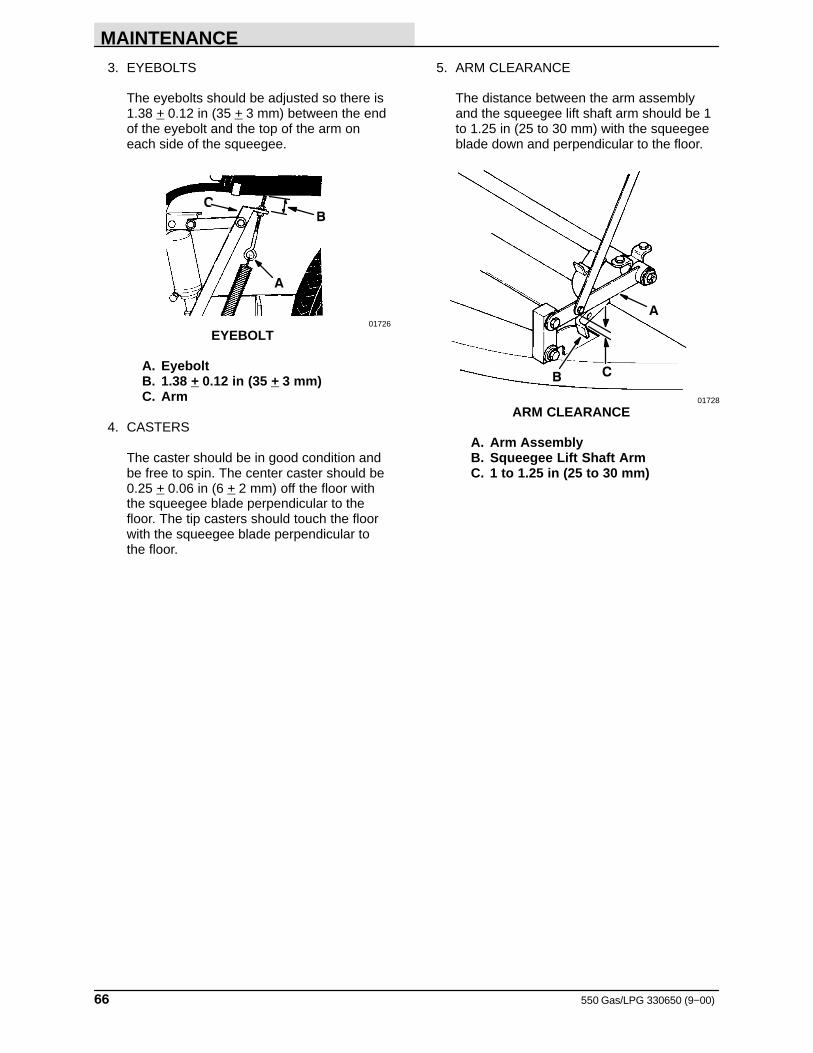
MAINTENANCE
550 Gas/LPG 330650 (9−00)66
3. EYEBOLTS
The eyebolts should be adjusted so there is1.38 + 0.12 in (35 + 3 mm) between the endof the eyebolt and the top of the arm oneach side of the squeegee.
C
A
B
01726
EYEBOLT
A. EyeboltB. 1.38 + 0.12 in (35 + 3 mm)C. Arm
4. CASTERS
The caster should be in good condition andbe free to spin. The center caster should be0.25 + 0.06 in (6 + 2 mm) off the floor withthe squeegee blade perpendicular to thefloor. The tip casters should touch the floorwith the squeegee blade perpendicular tothe floor.
5. ARM CLEARANCE
The distance between the arm assemblyand the squeegee lift shaft arm should be 1to 1.25 in (25 to 30 mm) with the squeegeeblade down and perpendicular to the floor.
B
A
C
01728
ARM CLEARANCE
A. Arm AssemblyB. Squeegee Lift Shaft ArmC. 1 to 1.25 in (25 to 30 mm)
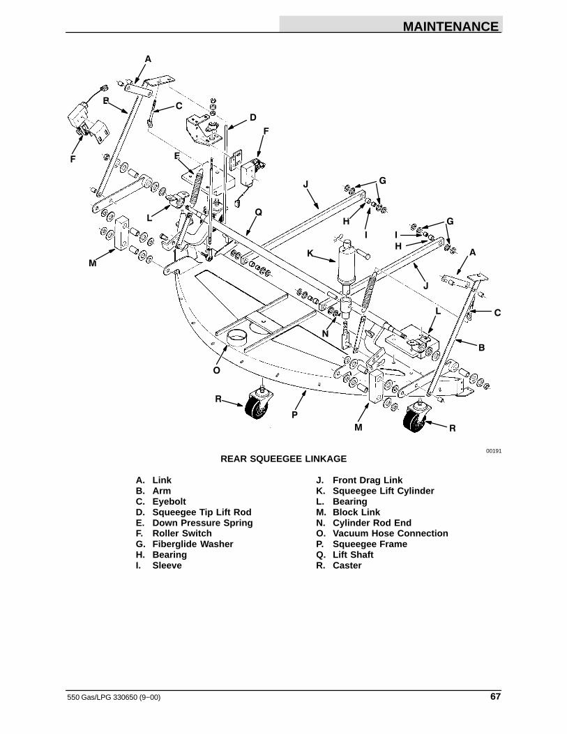
MAINTENANCE
67550 Gas/LPG 330650 (9−00)
D
J G
C
A
J
HQ
A
F
K
G
B
I
CB
F
L
M
O
P
M R
L
I
H
N
R
E
00191
REAR SQUEEGEE LINKAGE
A. Link J. Front Drag LinkB. Arm K. Squeegee Lift CylinderC. Eyebolt L. BearingD. Squeegee Tip Lift Rod M. Block LinkE. Down Pressure Spring N. Cylinder Rod EndF. Roller Switch O. Vacuum Hose ConnectionG. Fiberglide Washer P. Squeegee FrameH. Bearing Q. Lift ShaftI. Sleeve R. Caster
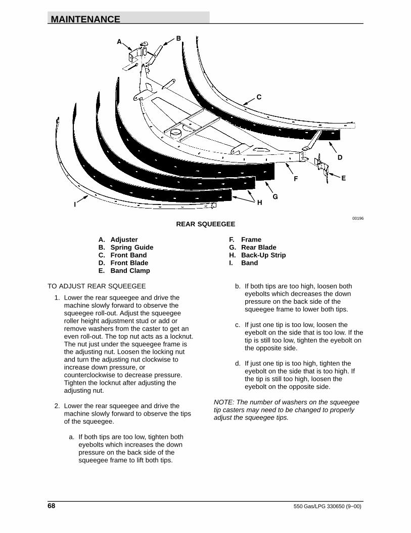
MAINTENANCE
550 Gas/LPG 330650 (9−00)68
AB
C
D
EF
GHI
00196
REAR SQUEEGEE
A. Adjuster F. FrameB. Spring Guide G. Rear BladeC. Front Band H. Back-Up StripD. Front Blade I. BandE. Band Clamp
TO ADJUST REAR SQUEEGEE
1. Lower the rear squeegee and drive themachine slowly forward to observe thesqueegee roll-out. Adjust the squeegeeroller height adjustment stud or add orremove washers from the caster to get aneven roll-out. The top nut acts as a locknut.The nut just under the squeegee frame isthe adjusting nut. Loosen the locking nutand turn the adjusting nut clockwise toincrease down pressure, orcounterclockwise to decrease pressure.Tighten the locknut after adjusting theadjusting nut.
2. Lower the rear squeegee and drive themachine slowly forward to observe the tipsof the squeegee.
a. If both tips are too low, tighten botheyebolts which increases the downpressure on the back side of thesqueegee frame to lift both tips.
b. If both tips are too high, loosen botheyebolts which decreases the downpressure on the back side of thesqueegee frame to lower both tips.
c. If just one tip is too low, loosen theeyebolt on the side that is too low. If thetip is still too low, tighten the eyebolt onthe opposite side.
d. If just one tip is too high, tighten theeyebolt on the side that is too high. Ifthe tip is still too high, loosen theeyebolt on the opposite side.
NOTE: The number of washers on the squeegeetip casters may need to be changed to properlyadjust the squeegee tips.
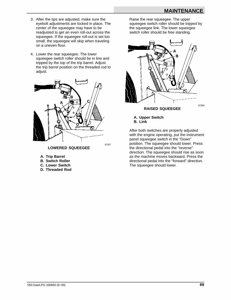
MAINTENANCE
69550 Gas/LPG 330650 (9−00)
3. After the tips are adjusted, make sure theeyebolt adjustments are locked in place. Thecenter of the squeegee may have to bereadjusted to get an even roll-out across thesqueegee. If the squeegee roll-out is set toosmall, the squeegee will skip when travelingon a uneven floor.
4. Lower the rear squeegee. The lowersqueegee switch roller should be in line andtripped by the top of the trip barrel. Adjustthe trip barrel position on the threaded rod toadjust.
CB
A
D
02357
LOWERED SQUEEGEE
A. Trip BarrelB. Switch RollerC. Lower SwitchD. Threaded Rod
Raise the rear squeegee. The uppersqueegee switch roller should be tripped bythe squeegee link. The lower squeegeeswitch roller should be free standing.
A
B
02358
RAISED SQUEEGEE
A. Upper SwitchB. Link
After both switches are properly adjustedwith the engine operating, put the instrumentpanel squeegee switch in the “Down”position. The squeegee should lower. Pressthe directional pedal into the “reverse”direction. The squeegee should rise as soonas the machine moves backward. Press thedirectional pedal into the “forward” direction.The squeegee should lower.
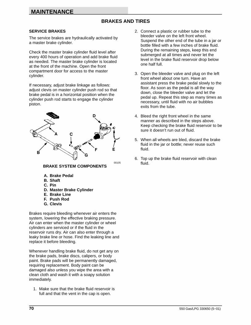
MAINTENANCE
550 Gas/LPG 330650 (5−01)70
BRAKES AND TIRES
SERVICE BRAKES
The service brakes are hydraulically activated bya master brake cylinder.
Check the master brake cylinder fluid level afterevery 400 hours of operation and add brake fluidas needed. The master brake cylinder is locatedat the front of the machine. Open the frontcompartment door for access to the mastercylinder.
If necessary, adjust brake linkage as follows:adjust clevis on master cylinder push rod so thatbrake pedal is in a horizontal position when thecylinder push rod starts to engage the cylinderpiston.
C
B
A
D
F
G
E
00105
BRAKE SYSTEM COMPONENTS
A. Brake PedalB. ShaftC. PinD. Master Brake CylinderE. Brake LineF. Push RodG. Clevis
Brakes require bleeding whenever air enters thesystem, lowering the effective braking pressure.Air can enter when the master cylinder or wheelcylinders are serviced or if the fluid in thereservoir runs dry. Air can also enter through aleaky brake line or hose. Find the leaking line andreplace it before bleeding.
Whenever handling brake fluid, do not get any onthe brake pads, brake discs, calipers, or bodypaint. Brake pads will be permanently damaged,requiring replacement. Body paint can bedamaged also unless you wipe the area with aclean cloth and wash it with a soapy solutionimmediately.
1. Make sure that the brake fluid reservoir isfull and that the vent in the cap is open.
2. Connect a plastic or rubber tube to thebleeder valve on the left front wheel.Suspend the other end of the tube in a jar orbottle filled with a few inches of brake fluid.During the remaining steps, keep this endsubmerged at all times and never let thelevel in the brake fluid reservoir drop belowone half full.
3. Open the bleeder valve and plug on the leftfront wheel about one turn. Have anassistant press the brake pedal slowly to thefloor. As soon as the pedal is all the waydown, close the bleeder valve and let thepedal up. Repeat this step as many times asnecessary, until fluid with no air bubblesexits from the tube.
4. Bleed the right front wheel in the samemanner as described in the steps above.Keep checking the brake fluid reservoir to besure it doesn’t run out of fluid.
5. When all wheels are bled, discard the brakefluid in the jar or bottle; never reuse suchfluid.
6. Top up the brake fluid reservoir with cleanfluid.
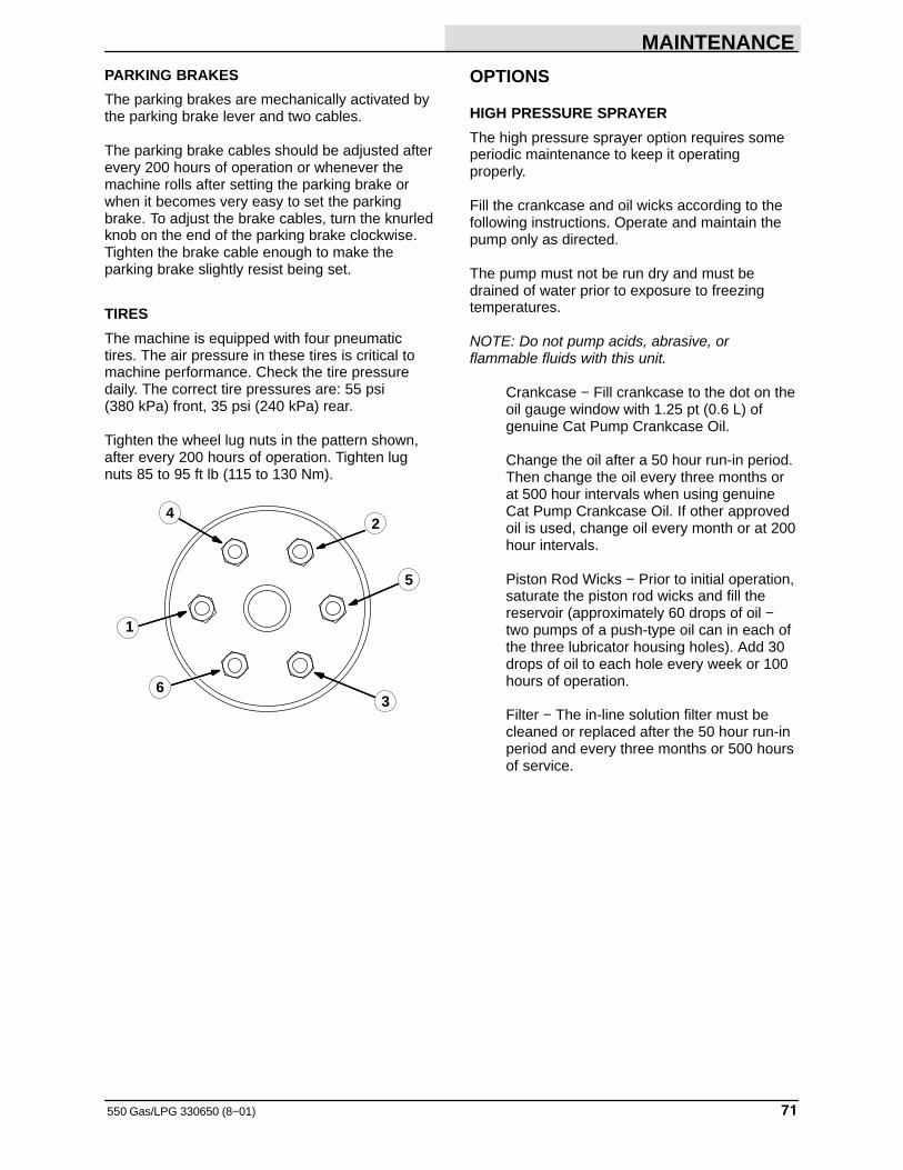
MAINTENANCE
71550 Gas/LPG 330650 (8−01)
PARKING BRAKES
The parking brakes are mechanically activated bythe parking brake lever and two cables.
The parking brake cables should be adjusted afterevery 200 hours of operation or whenever themachine rolls after setting the parking brake orwhen it becomes very easy to set the parkingbrake. To adjust the brake cables, turn the knurledknob on the end of the parking brake clockwise.Tighten the brake cable enough to make theparking brake slightly resist being set.
TIRES
The machine is equipped with four pneumatictires. The air pressure in these tires is critical tomachine performance. Check the tire pressuredaily. The correct tire pressures are: 55 psi (380 kPa) front, 35 psi (240 kPa) rear.
Tighten the wheel lug nuts in the pattern shown,after every 200 hours of operation. Tighten lugnuts 85 to 95 ft lb (115 to 130 Nm).
2
3
4
1
5
6
OPTIONS
HIGH PRESSURE SPRAYER
The high pressure sprayer option requires someperiodic maintenance to keep it operatingproperly.
Fill the crankcase and oil wicks according to thefollowing instructions. Operate and maintain thepump only as directed.
The pump must not be run dry and must bedrained of water prior to exposure to freezingtemperatures.
NOTE: Do not pump acids, abrasive, orflammable fluids with this unit.
Crankcase − Fill crankcase to the dot on theoil gauge window with 1.25 pt (0.6 L) ofgenuine Cat Pump Crankcase Oil.
Change the oil after a 50 hour run-in period.Then change the oil every three months orat 500 hour intervals when using genuineCat Pump Crankcase Oil. If other approvedoil is used, change oil every month or at 200hour intervals.
Piston Rod Wicks − Prior to initial operation,saturate the piston rod wicks and fill thereservoir (approximately 60 drops of oil −two pumps of a push-type oil can in each ofthe three lubricator housing holes). Add 30drops of oil to each hole every week or 100hours of operation.
Filter − The in-line solution filter must becleaned or replaced after the 50 hour run-inperiod and every three months or 500 hoursof service.
SPECIFICATIONS
550 Gas/LPG 330650 (2−06)72
MACHINE SPECIFICATIONS
POWER TYPE
CONTINENTAL ENGINES − (For machinesbelow serial number 006409)
Engine manufacturer/model − Continental TM27Engine type − pistonIgnition − breaker−less type sparkCycle − 4Aspiration − naturalCylinders − 4Bore − 3.58 in (90 mm)Stroke − 4.06 in (105 mm)Displacement − 164 cu in (2.7 L)Net power:
58 hp (43 kw) @ 2400 rpm governed70 hp (52 kw) @ 3000 rpm maximum
Fuels − gasoline, 85 octane unleaded, or LPGCooling system − waterElectrical system − 12 V nominal, 42 A alternator
GM ENGINES − (For machines serial number006409 and above)
Engine manufacturer/model − GM PowertrainEngine type − pistonIgnition − solid state distributorCycle − 4Aspiration − naturalCylinders − 4Bore − 4.00 in (101.60 mm)Stroke − 3.60 in (91.44 mm)Displacement − 181 cu in (3.0 L)Fuels − gasoline, 85 octane unleaded, or LPGNet power: gasoline
NA hp ( kw) @ NA rpm governed 83 hp (62 kw) @ 3000 rpm maximum
Net power: LPG 65 hp (49 kw) @ 2400 rpm governed NA hp ( kw) @ NA rpm maximum
Cooling system − waterElectrical system − 12 V nominal, 50 A alternator
POWER TRAIN
Propelling − hydraulic drive motors (2)Scrub brush − hydraulic drive motors (2)Vacuum fan − belt driven
STEERING
Type − articulated framePower source − double action hydraulic cylinderEmergency steering − manual
BRAKING SYSTEM
Service brakes − hydraulic caliper disc brakes(2), (one per front wheel) foot brake mastercylinder actuated.
Parking brakes − mechanical caliper disc brakes(2), (one per front wheel), cable actuated.
SUSPENSION SYSTEM
Front − two 8.00 x 16.5 6-ply rating tubeless tiresRear − two 8.00 x 16.5 6-ply rating tubeless tires
SYSTEM FLUID CAPACITIES
(For machines below serial number 007006)Hydraulic system, reservoir − 11.5 gal (45 L)
Hydraulic system, total system − 13.8 gal (52 L)
(For machines serial number 007006 and above)Hydraulic system, reservoir − 14.2 gal (54 L)
Hydraulic system, total system − 18.3 gal (69 L)
Standard solution tank − 140 gal (530 L)
Standard recovery tank − 120 gal (455 L)
SRS solution tank − 265 gal (1000 L)
SRS cleaning solution tank − 10 gal (37 L)
CONTINENTAL ENGINES − (For machinesbelow serial number 006409)
Engine cooling system: radiator − 6.4 qt (6 L)
total system − 13.4 qt (13 L)
Fuel tank, LPG − 33 lb (15 kg)
Engine lubricating oil − 7 qt (6.6 L)
GM ENGINES − (For machines serial number006409 and above)
Engine cooling system:radiator/hoses − 8.75 qt (8 L)total system − 12.75 qt (12 L)
Fuel tank, LPG − 33 lb (15 kg)
Engine lubricating oil with filter − 5.0 qt (4.7 L)
SPECIFICATIONS
73550 Gas/LPG 330650 (2−06)
GENERAL MACHINEDIMENSIONS/CAPACITIES
Length − 156 in (3960 mm)
Width − 61 in (1550 mm)
Height − 61 in (1550 mm)Height with overhead guard − 84 in
(2130 mm)
Track, front − 46.7 in (1185 mm)Track, rear − 45.3 in (1150 mm)
Wheel base − 58.75 in (1490 mm)
Scrub brush (2), path width − 50 in (1270 mm)Scrub brush (2), diameter − 11 in (280 mm)
Rear squeegee path width − 56.5 in (1435 mm)
Debris hopper capacity − 2.6 cu ft (0.073 m3)
MACHINE WEIGHTS
GVWR − 7200 lb (3270 kg)
GENERAL MACHINE PERFORMANCE
Maximum forward speed − 9 mph (14.5 km/h)Maximum reverse speed − 5 mph (8 km/h)Turning radius, right − 109 in (2770 mm)Turning radius, left − 100 in (2540 mm)Maximum rated climb and descent angle − 10�Maximum rated climb and ascent angle when
tanks are full − 8�
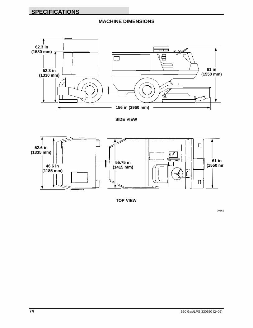
SPECIFICATIONS
550 Gas/LPG 330650 (2−06)74
MACHINE DIMENSIONS
SIDE VIEW
TOP VIEW
156 in (3960 mm)
62.3 in(1580 mm)
52.3 in(1330 mm)
61 in(1550 mm)
61 in(1550 mm
55.75 in(1415 mm)46.6 in
(1185 mm)
52.6 in(1335 mm)
00362
INDEX
75550 Gas/LPG 330650 (3−11)
A
Adjusting rear squeegee blade deflection, 68
Adjusting side squeegee blade deflection, 64
Air filter, 40
Air filter service indicator, 40
Air intake system, 40
Aisle turn, 73
Alternator and radiator fan belt, To adjustalternator and radiator fan belt, 55
Ammeter, 14
B
Battery, 54Ammeter, 14charging system light, 14
Belts, 55Alternator and radiator fan belt, 55Vacuum fan drive belt, 55
To adjust vacuum fan drive belt, 55
Brake pedal, 13
Brakes, 70Machine specifications, 72Parking, Adjustment, 71Service, 70
BrushesScrub brush lever, 13Scrub head position lever, 17
Button, Horn, 17
Bypass valve, 24
C
Capacities, 73
Carburetor, 43, 47Idle adjustment, 43
Chains, 55
Changing LPG fuel tank, 46
Check engine light, 14
Circuit breakers, 16
Control panelAmmeter, 14charging system light, 14Circuit breakers, 16Engine choke knob, 17Engine coolant temperature, 16Engine hour meter, 15Engine oil pressure, 16engine oil pressure light, 16Fuel level gauge, 15
Fuses, 15Hazard light switch, 15Operating lights switch, 15Panel lamp, 15Rotating light switch, 15Scrub brush lever, 13Scrub head position lever, 17Solution lever, 17Squeegee position lamp, 14Squeegee switch, 16SRS cleaning solution flow knob, 17SRS liquid low level lamps, 17Tank drain lamp, 15Throttle lever, 17Throttle switch, 17
Controls, 11, 12Ammeter, 14Brake pedal, 13Check engine light, 14Circuit breakers, 16Directional pedal, 13Engine choke knob, 17Engine coolant temperature gauge, 16Engine hour meter, 15Engine oil pressure gauge, 16Fuel level gauge, 15Fuses, 15Hazard light switch, 15Horn button, 17Ignition switch, 14Operating lights switch, 15Operation, 10–23Parking brake lever, 14Rotating light switch, 15Scrub brush lever, 13Scrub brush pressure lamp, 15Scrub head lock lever, 13Scrub head position lever, 17Solution lever, 17Squeegee position lamp, 14Squeegee switch, 16SRS cleaning solution flow knob, 17SRS liquid low level lamps, 17Steering wheel, 17Tank drain lamp, 15Throttle lever, 17Throttle switch, 17
Cylinder head, 52
Cylinder head bolt tightening, 52
INDEX
550 Gas/LPG 330650 (3−11)76
D
Debris hopper, Empty and clean, 21
Dimensions, 73
Directional pedal, 13
Distributor, 50Distributor ignition timing, 51
Distributor ignition timing, 51
Double scrubbing, 21
E
ElectricalBattery, 54Circuit breakers, 16Fuses, 15Ignition switch, 14
Electrical system, 50, 54
Engine, 39–41Air filter, 40Air filter service indicator, 40Air intake system, 40Alternator and radiator fan belt, 55Carburetor, 43
Idle adjustment, 43Cooling system, 39Cylinder head, 52
Cylinder head bolt tightening, 52Distributor, 50Electrical system, 50Engine choke knob, Light, 17Engine coolant temperature, Light, 16Fuel filters, 42, 43In−line fuel filter, 43Fuel system−gasoline, 42, 43Fuel system−LPG, 44Governor, 49LPG, Carburetor, 47Lubrication, 32, 39Machine specifications, 72Oil pressure, Light, 16oil pressure light, 16PCV system, 53Spark Plugs, 50Throttle lever, Light, 17Throttle switch, Light, 17To replace air filter element, 41, 42Tune−up chart, 53
Engine choke knob, 17
Engine coolant temperature gauge, 16
Engine hour meter, 15
Engine oil pressure gauge, 16
F
Fluid capacities, Machine specifications, 72
Fuel filters, 42, 43
In-line fuel filter, 43
Fuel fiter lock, 47
Fuel level gauge, 15
Fuel system-gasoline, 42, 43
Fuel system-LPG, 44
Fuel tank, Changing LPG, 46
Fuses, 15
G
Gauge, Fuel level, 15
GaugesAmmeter, 14Engine coolant temperature, 16Engine oil pressure, 16
Governor, 49To adjust governor, 49
H
Hazard light switch, 15
High pressure sprayer, 23, 71
Horn button, 17
Hydraulic components troubleshooting, 38
Hydraulic fluid, 35
Hydraulic fluid filter, 37
Hydraulic fluid reservoir, 35
Hydraulic fluid reservoir breather, 37
Hydraulic hoses, 37
Hydraulics, 35–37Components troubleshooting, 38Fluid, 35–37Fluid level, 36Hoses, 37Hydraulic fluid filter, 37Hydraulic fluid reservoir breather, 37Reservoir, 35
I
Ignition switch, 14
INDEX
77550 Gas/LPG 330650 (3−11)
J
Jack points, 26
K
KnobsEngine choke knob, 17SRS cleaning solution flow knob, 17
L
LampsPanel lamp, 15Scrub brush pressure lamp, 15Squeegee position lamp, 14SRS liquid low level lamps, 17Tank drain lamp, 15
Leveling the rear squeegee, 65
LeversParking brake, 14Scrub brush, 13Scrub head lock lever, 13Scrub head position, 17Solution lever, 17Throttle lever, 17
Lightsbattery charging system, 14Check engine, 14engine oil pressure, 16Hazard light switch, 15Operating lights switch, 15Rotating light switch, 15Squeegee position lamp, 14
LPGChanging the fuel tank, 46Fuel filter lock, 47Oil pressure switch, 47Vaporizer−regulator, 47
LPG fuel, Troubleshooting, 48
LPG fuel troubleshooting, 48
Lubrication, 32Engine, 32, 39Machine pivot, 33Rear squeegee casters, 34Rear wheels, 34Scrub brush idler plugs, 34Scrub head hinges, 34Scrub head pivot, 33Vacuum fan shaft, 32
M
Machine components, 10
Machine dimensions, 74
Machine jacking, 26
Machine leaks, 21
Machine operation, 18
Machine pivot, 33
Machine specifications, 72–74Braking system, 72Machine capacities, 73Machine dimensions, 73Machine performance, 73Machine wieghts, 73Power train, 72Power type, 72Steering, 72Suspension system, 72System fluid capacities, 72
Machine tie down location, 25
Machine wieghts, Machine specifications, 73
Maintenance, Intervals, 30
Maintenance chart, 30
N
Normal scrubbing information, 18
O
Oil pressure switch, 47
Operating lights switch, 15
Operation, 9–54
Operation on grades, 21
Operator seat, 13
Options, 71Hazard light switch, 15High pressure sprayer, 23–25, 71Operating lights switch, 15Panel lamp, 15Rotating light switch, 15SRS cleaning solution flow knob, 17SRS liquid low level lamps, 17Vacuum wand, 23–25
Options operation, 23–25
INDEX
550 Gas/LPG 330650 (3−11)78
P
Panel lamp, 15
Parking brake, 71
Parking brake lever, 14
PCV system, 53
PedalsBrake, 13Directional, 13
Pivot lock pin, 14
Post operation checklist-engine operating, 21
Post operation checklist-engine stopped, 21
Power train, Machine specifications, 72
Pre‐start checklist, 18
R
Radiator, 39Coolant level, 39Coolant type, 39Flushing system, 39
Rear squeegee, 64–66Blade deflection, 68Leveling, 65Replacing blades, 65–67
Rear squeegee casters, 34
Rear wheels, 34
Recommended first 50-hour machineinspection, 29–50
Recovery tank, 60Drain and clean, 21Tank drain lamp, 15
Replacing rear squeegee blades, 65–67
Replacing side squeegee blades, 64
Rotating light switch, 15
S
SafetyLabels, 7Precautions, 5–7
Scrub brush idler plugs, Lubrication, 34
Scrub brush lever, 13
Scrub brush pressure lamp, 15
Scrub brushes, 58–61Check, 21Checking brush pattern, 21Lever, 13, 17Replacing, 58–60
Scrub head, 56–59To adjust scrub brush pattern, 56To adjust scrub head pattern, 56
Scrub head hinges, Lubrication, 34
Scrub head lock lever, 13
Scrub head pivot, 33
Scrub head position lever, 17
Scrubbing, Double, 21
Seat, 13Adjustment, 13
Side squeegee, Blade deflection, 64
Side squeegees, 64Replacing blades, 64
Solution dispensing tube, 63
Solution lever, 17
Solution system, 60Recovery tank, 60Solution dispensing tube, 63Solution lever, 17SRS cleaning solution flow knob, 17SRS liquid low level lamps, 17SRS metering solution pump, 63SRS solution tank, 62SRS water spray deflector, 61Troubleshooting, 63Water spray deflector, 60
Spark plugs, 50
Squeegee position lamp, 14
Squeegee switch, 16
Squeegees, 64–66Blade deflection, 64, 68Deflection, 21Leveling, 65Rear, 64–66Replacing rear blades, 65–67Replacing side blades, 64Side, 64Switch, 16
SRS cleaning solution flow knob, 17
SRS liquid low level lamps, 17
SRS metering solution pump, 63
SRS solution tank, 62
SRS water spray deflector, 61
Steering, Machine specifications, 72
Steering wheel, 17
Storing machine, 27
Suspension, Machine specifications, 72
INDEX
79550 Gas/LPG 330650 (3−11)
SwitchesHazard light switch, 15Ignition, 14Operating lights switch, 15Rotating light switch, 15Squeegee, 16Throttle switch, 17
T
Tank drain lamp, 15
Throttle lever, 17
Throttle switch, 17
Tie down location, 25
Tires, 70, 71
To adjust alternator and radiator fan belt, 55
To adjust governor, 49
To adjust vacuum fan drive belt, 55
To drain and clean recovery tank and emptyhopper, 20–22
To fill solution tank, 19
To replace air filter element, 41, 42
To scrub, 19
To start machine, 18
To stop machine, 21
Towing and transporting machine, 24
Towing machine, 24
Towing the machine, 24
Transporting machine, 24
Transporting the machine, 24
Travel speed, 73
Troubleshooting, 22–24Hydraulic components, 38LPG fuel, 48Solution system, 63
Troubleshooting solution system, 63
Tune-up chart, 53
V
Vacuum fan drive belt, 55
Vacuum fan shaft, 32
Vacuum hoses, Check, 21
Vacuum wand, 23
Vaporizer-regulator, 47
W
Water spray deflector, 60

INDEX
550 Gas/LPG 330650 (3−11)80