Embed Size (px)
Citation preview
For Technical Service Call Your Local Bio-Rad Office or in the U.S. Call 1-800-4BIORAD (1-800-424-6723)
Gene Pulser® IIElectroporation System
Instruction Manual
Catalog Numbers165-2105, 165-2106, 165-2107, 165-2108, 165-2109, 165-2110

Life ScienceGroup
2000 Alfred Nobel DriveHercules, California 94547Telephone (510) 741-1000Fax: (510) 741-5800www.bio-rad.com
Australia, Bio-Rad Laboratories Pty. Ltd., Block Y, Unit 1, Regents Park Industrial Estate, 391 Park Road, Regents Park, NSW 2143Phone 02 9914 2800 • Fax 02 9914 2889Austria, Bio-Rad Laboratories Ges.m.b.H., Auhofstraße 78D, A-1130 Wien • Phone (01)-877 89 01 • Fax (01)-876 56 29Belgium, Bio-Rad Laboratories S.A.-N.V., Begoniastraat 5, B-9810 Nazareth • Phone 09-385 55 11 • Free Phone 0800/97032 • Fax 09-385 65 54Brazil, Bio-Rad Laboratories (Brazil), Rua dos Invalidos 212 - 5 andar, Lapa - Rio de Janeiro - RJ, CEP 20331-020 • Phone 55 21 507 6191Canada, Bio-Rad Laboratories (Canada) Ltd., 5671 McAdam Road, Mississauga, Ontario L4Z 1N9 • Phone (905) 712-2771 • Fax (905) 712-2990China, Bio-Rad China (Beijing), Rm 615, Shang Fang Plaza, No. 27, North Third Round Center Road, West District, Beijing 100029 Phone 86-10-8201-1366/68 • Fax 86-10-8201-1367Denmark, Bio-Rad Laboratories, Generatorvej 8 C, 2730 Herlev • Phone 45 44 52-1000 • Fax 45 44 52-1001 Finland, Bio-Rad Laboratories, Pihatörmä 1A, FIN-02240 Espoo • Phone 358 (0)9 804 2200 • Fax 358 (0)9 804 1110France, Bio-Rad Laboratories, 3, Boulevard Raymond Poincaré, 92430 Marnes-la-Coquette • Phone 01 47 95 69 65 • Fax 01 47 41 9133Germany, Bio-Rad Laboratories GmbH, Heidemannstraße 164, D-80939 München, Postfach 45 01 33, D-80901 MünchenPhone 089 318 84-177 • Fax 089 318 84-123Hong Kong, Bio-Rad Pacific Ltd., Unit 1111, 11/F, New Kowloon Plaza, 38 Tai Kok Tsui Road, Tai Kok Tsui, KowloonPhone 852-2789-3300 • Fax 852-2789-1257India, Bio-Rad Laboratories (India) Pvt. Ltd., B&B1, Enkay Towers Vanijyanikunj, Udhyog Vihar Phase V, Gurgaon, Haryana 122016 Phone (91-124)-6398112/113/114 • Fax (91-124)-6398115Israel, Bio-Rad Laboratories, Ltd., 14 Homa Street, P.O. Box 5044, Rishon Le Zion 75150 • Phone 03 951 4124 • Fax 03 951 4129Italy, Bio-Rad Laboratories S.r.l., Via M. Peroglio 23, 00144 Rome • Phone 34 91 590 5200 • Fax 34 91 590 5211Japan, Nippon Bio-Rad Laboratories KK, 7-18 Higashi-Nippori 5-chome, Arakawa-ku Tokyo 116-0014 • Phone 03-5811-6270 • Fax 03-5811-6272Korea, Bio-Rad Korea Ltd., Cambridge Building, 1461-15 Seocho-Dong Seocho-Ku, Seoul 137-070 • Phone 82-2-3473-4460 • Fax 82-2-3472-7003Latin America, Bio-Rad Latin America, 14100 Palmetto Frontage Road, Suite 101, Miami Lakes, Florida USA 33016 • Phone 305-894-5950 • Fax 305-894-5960 Mexico, Bio-Rad Laboratorios Mexico, Adolfo Prieto No. 1653, Col. De Valle, CP. 03100, Mexico D.F. • Phone 52 5 534 2552 to 54 • Fax 52 5 524 5971 The Netherlands, Bio-Rad Laboratories B.V., Fokkerstraat 10, 3905 KV Veenendaal • Phone 0318-540666 • Fax 0318-542216New Zealand, Bio-Rad Laboratories Pty Ltd., PO Box 300-571, Albany, Auckland • Phone 64-9-4152280 • Fax 64-9-443 3097Norway, Bio-Rad Laboratories, Johan Scharffenbergs vei 91, N-0694 Oslo • Phone 47-23-38-41-30 • Fax 47-23-38-41-39Russia, Bio-Rad Laboratorii, ul. Butirskaya 79 "B", office 156 RF-125015 Moscow • Phone 7 095 979 98 00 • Fax 7 095 979 98 56 Singapore, Bio-Rad Laboratories, Singapore, 211 Henderson Rd. #03-02, Henderson Industrial Park, 159552 • Phone 65-2729877 • Fax 65-2734835Spain, Bio-Rad Laboratories, S.A., Lopez de Hoyos, 245-247, 28043 Madrid • Phone 34-91-590-5200 • Fax 34-91-590-5211Sweden, Bio-Rad Laboratories AB, Vintergatan 1, Box 1097, S-172 22 Sundbyberg • Phone 46 (0)8-55 51 27 00 • Fax 46 (0)8-55 51 27 80Switzerland, Bio-Rad Laboratories AG, Nenzlingerweg 2, CH-4153 Reinach • Phone 061-717-9555 • Fax 061-717-9550United Kingdom, Bio-Rad Laboratories Ltd., Bio-Rad House, Maylands Avenue, Hemel Hempstead, Hertfordshire HP2 7TDPhone 0181 328 2000 • Free Phone 0800-181134 • Fax 01442-259118
00-000 0000 Sig 1200Bulletin 0000 US/EG Rev A
Bio-RadLaboratories
M1652105 Rev C
WarrantyThe Gene Pulser II electroporation system is warranted against defects in materials and workmanship for
1 year. If any defects occur in the instruments or accessories during this warranty period, Bio-Rad Laboratorieswill repair or replace the defective parts at its discretion without charge. The following defects, however, arespecifically excluded:
1. Defects caused by improper operation.
2. Repair or modification done by anyone other than Bio-Rad Laboratories or an authorized agent.
3. Damage caused by substituting alternative parts.
4. Use of fittings or spare parts supplied by anyone other than Bio-Rad Laboratories.
5. Damage caused by accident or misuse.
6. Damage caused by disaster.
7. Corrosion caused by improper solvent or sample.
This warranty does not apply to parts listed below:
Fuses
For any inquiry or request for repair service, contact Bio-Rad Laboratories. Inform Bio-Rad of the modeland serial number of your instrument.
IMPORTANT: This Bio-Rad instrument is designed and certified to meet IEC 1010-1* safety standards. Certified products are safe to use when operated in accordance with the instruction manual.This instrument should not be modified or altered in any way. Alteration of this instrument will:
Void the manufacturer’s warranty
Void the IEC 1010-1 safety certification
Create a potential safety hazard
Bio-Rad Laboratories is not responsible for any injury or damage caused by the use of this instrument forpurposes other than those for which it is intended, or by modifications of the instrument not performed byBio-Rad Laboratories or an authorized agent.
*IEC 1010-1 is an internationally accepted electrical safety standard for laboratory instruments.
Table of ContentsPage
Section 1 Introduction .............................................................................................11.1 Gene Pulser II System Description .......................................................................1
Section 2 Unpacking and System Installation.......................................................22.1 Safety .....................................................................................................................22.2 Unpacking The System Components....................................................................32.3 Setting Up The System..........................................................................................3
Section 3 Guide to Switches and Keypads.............................................................73.1 Gene Pulser II Unit Control Panel ........................................................................83.2 Pulse Controller II Front Panel ...........................................................................133.3 Pulse Controller PLUS Front Panel ....................................................................143.4 Capacitance Extender II Front Panel ..................................................................153.5 Capacitance Extender PLUS Front Panel ...........................................................16
Section 4 Operation................................................................................................164.1 Instructions for Using the Gene Pulser II unit and
the Pulse Controller II (or PLUS) Accessory .....................................................164.2 Instructions for Using the Gene Pulser II unit with
the Capacitance Extender II (or PLUS ) Accessory Module .............................17
Section 5 The Pulse Trac™ system.........................................................................185.1 Pulse Trac System Description ...........................................................................185.2 Pulse Trac Diagnostic Algorithm........................................................................18
Section 6 Instrument Diagnostics and Troubleshooting....................................20
Section 7 Specifications and Product Information.............................................217.1 System Specifications .........................................................................................217.2 Product Information ............................................................................................22
Appendix A Review of Electroporation Fundamentals ..........................................22
i

ii
Section 1Introduction
This manual will familiarize you with the features and the operation of the Gene Pulser IIapparatus with its accessory components, the Pulse Controller II or Pulse Controller PLUS module and the Capacitance Extender II or Capacitance Extender PLUS module.
Section 2, Unpacking and System Installation, contains important safety information aswell as instructions on unpacking and connecting the Gene Pulser instrument to the PulseController II or Pulse Controller PLUS module and the Capacitance Extender II or CapacitanceExtender PLUS module for electroporation.
Use Section 3, Guide to Switches and Keypads, to learn about the controls and read-outinformation that the Gene Pulser II apparatus provides with the Pulse Controller II or PulseController PLUS module and Capacitance Extender II or Capacitance Extender PLUS module.
In Section 4, Operation, you can examine basic set up and protocols for both prokaryotic andeukaryotic electroporation.
1.1 Gene Pulser II System DescriptionThe new Gene Pulser II system* is a completely redesigned electroporation system, which
offers improved performance, flexibility, sample protection, and safety. The Gene Pulser II system uses the Pulse Trac™ waveform delivery system to generate the most accurate expo-nential decay pulses possible for optimal cell transformation within an electroporation cuvette.The Pulse Trac delivery system accurately calculates the time constant of each pulse based onwhat is actually delivered to the sample. The revolutionary Pulse Trac waveform delivery system provides
• Sample conductivity measurement integrated with pulse output for true waveform deliveryregardless of sample
• Internal calibration and circuit monitoring program for accurate pulse delivery throughout thelifetime of the unit
• Improved time constant accuracy
Other features of the new Gene Pulser II system include
• Error free assembly, since each module uses unique cable connectors, keyed to fit only in theproper orientation and location
• Automatic display of time constant after every pulse, to make it easier to record this essen-tial pulse parameter
• Easier optimization of novel prokaryotic applications with a wider range of high voltagecapacitors (1.0 , 3.0, 10, 25, and 50 µF) in the Gene Pulser II unit
• Pinpointing of optimal field strengths, with voltage selection in 2 V increments for mam-malian cell electroporation (low voltage/high capacitance) and operation at a higher maximumvoltage (up to 500 V). In addition, voltage selection in 10 V increments for bacterial (high volt-age/low capacitance) electroporation
• Increased control of high voltage pulses used for bacteria and yeast electro-transformation withthe five new resistors in the Pulse Controller PLUS module
* United States Patent numbers 4,750,100; 4,910,149 and patents in application.
1
• Expanded range of precision capacitors for reproducible mammalian cell electroporation;25 µF–3,275 µF with the Capacitance Extender PLUS module or 25 µF–1,075 µF with theCapacitance Extender II module. This permits greater time constant reproducibility and flex-ibility with electronically calibrated capacitors in 25 µF increments. At any time, the PulseTrac circuitry can verify and calibrate these capacitors within ±10% variation for the ulti-mate in pulse reproducibility and precision.
• Designed and certified to meet IEC 1010 safety standards
• Entire system is completely protected from sample arcs, regardless of module or sample used
• Expanded safety, with charges automatically diverted safely to ground whenever the circuitis interrupted during pulse delivery.
The Gene Pulser II unit may be used with either of two new types of accessory modules. Forelectroporation of bacteria and yeast, use the Pulse Controller II or Pulse Controller PLUS mod-ule. For electroporation of mammalian cells and embryonic tissue, use the Capacitance ExtenderII or Capacitance Extender PLUS module.
Section 2Unpacking and System Installation
Read this important information before you use the Gene Pulser II electroporation devicewith the Pulse Controller II or Pulse Controller PLUS module and the Capacitance Extender IIor Capacitance Extender PLUS module.
2.1 SafetyThis instrument is intended for laboratory use only.
This product conforms to the “Class A” standards for electromagnetic emissions intended forlaboratory equipment applications. It is possible that emissions from this product may interferewith some sensitive appliances when placed nearby or in the same circuit as those appliances. Theuser should be aware of this potential and take appropriate measures to avoid interference.
No part of the Gene Pulser II system should be used if obvious external case damage hasoccurred or the electronic displays are not functioning as described in the manual. This instru-ment is only to be used with the components provided (or their authorized additions orreplacements) including, but not limited to, supplied cables and shocking chamber. The operatingtemperature range for the Gene Pulser II system and its associated components is 0–35 °C.
This Bio-Rad instrument is designed and certified to meet IEC 1010* safety standards.There are no user serviceable parts within the unit. The operator should make no attempt toopen any case cover or defeat any safety interlock. This instrument must not be altered or mod-ified in any way. Alteration of this instrument will
• Void the manufacturer’s warranty
• Void the IEC 1010 safety certification
• Create a potential safety hazard
Bio-Rad is not responsible for any injury or damage caused by the use of this instrument forpurposes other than those for which it is intended or by modification of the instrument not per-formed by Bio-Rad or an authorized agent.
2
*IEC 1010 is an internationally accepted electrical safety standard for laboratory instruments.
2.2 Unpacking the System ComponentsRemove all packing material and connect components on a flat, dry surface near an appro-
priate electrical outlet.
The Gene Pulser II apparatus should arrive complete with the following components
1 Gene Pulser II unit
1 Gene Pulser II shocking chamber (clear plastic cover with attached red and blackcables, base with attached leads, and cuvette holder)
1 Cuvette rack
5 0.1 cm cuvettes
5 0.2 cm cuvettes
5 0.4 cm cuvettes
1 Warranty card (please complete and return)
The Pulse Controller II or Pulse Controller PLUS accessory to the Gene Pulser II unit shouldarrive complete with the following components
1 Pulse Controller II or Pulse Controller PLUS module (with integrated leads)
1 Warranty card (please complete and return)
The Capacitance Extender II or Capacitance Extender PLUS accessory to the Gene PulserII unit should arrive complete with the following components
1 Capacitance Extender II or Capacitance Extender PLUS module accessory (withintegrated leads)
1 RS 232 readout cable (25 pin)
1 Warranty card (please complete and return)
2.3 Setting Up the System
Setting Up the Gene Pulser II Unit
To use the Gene Pulser II unit with either the Pulse Controller II or Pulse Controller PLUSand the Capacitance Extender II or Capacitance Extender PLUS, follow this procedure.
1. Verify Gene Pulser II unit voltage compatibility with local electrical output by checking thatthe red voltage switches in the back of the unit are in the proper position (Figure 2.1).
• Units operating in the 110-120 V range must have the red voltage switches positioned so 115V is visible on both switches.
• Units operating in the 220-240 V range must have the red voltage switches positioned so 230V is visible on both switches.
2. Attach the power cord to the three pronged receptacle on the back of the Gene Pulser II unit(Figure 2.1) and plug the unit into an appropriate electrical outlet or power strip.
3
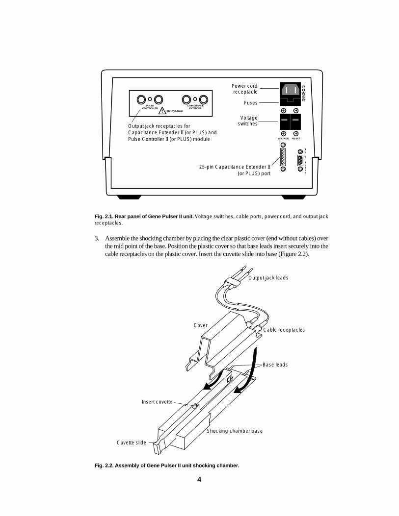
Fig. 2.1. Rear panel of Gene Pulser II unit. Voltage switches, cable ports, power cord, and output jackreceptacles.
3. Assemble the shocking chamber by placing the clear plastic cover (end without cables) overthe mid point of the base. Position the plastic cover so that base leads insert securely into thecable receptacles on the plastic cover. Insert the cuvette slide into base (Figure 2.2).
Fig. 2.2. Assembly of Gene Pulser II unit shocking chamber.
HIGH-VOLTAGE
CAPACITANCEEXTENDER
VOLTAGE SELECT
PULSECONTROLLER
POWER
TO
PRINTER
4
Output jack receptacles forCapacitance Extender II (or PLUS) andPulse Controller II (or PLUS) module
25-pin Capacitance Extender II(or PLUS) port
Cover
Insert cuvette
Cuvette slide
Shocking chamber base
Base leads
Cable receptacles
Output jack leads
Power cordreceptacle
Fuses
Voltageswitches
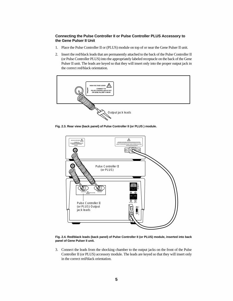
Connecting the Pulse Controller II or Pulse Controller PLUS Accessory tothe Gene Pulser II Unit
1. Place the Pulse Controller II or (PLUS) module on top of or near the Gene Pulser II unit.
2. Insert the red/black leads that are permanently attached to the back of the Pulse Controller II(or Pulse Controller PLUS) into the appropriately labeled receptacle on the back of the GenePulser II unit. The leads are keyed so that they will insert only into the proper output jack inthe correct red/black orientation.
Fig. 2.3. Rear view (back panel) of Pulse Controller II (or PLUS ) module.
Fig. 2.4. Red/black leads (back panel) of Pulse Controller II (or PLUS) module, inserted into backpanel of Gene Pulser II unit.
3. Connect the leads from the shocking chamber to the output jacks on the front of the PulseController II (or PLUS) accessory module. The leads are keyed so that they will insert onlyin the correct red/black orientation.
HIGH-VOLTAGE
CAPACITANCEEXTENDER
VOLTAGE SELECT
PULSECONTROLLER
DISCONNECT 25-PIN CABLE FROM GENE PULSER II OR CAPACITANCEEXTENDER BEFORE REMOVING CAPACITANCE EXTENDER HV OUT LEADS.
CONNECT TO CAPACITANCE EXTENDER CONTROL ON GENE PULSER II REAR.
POWER
TO
PRINTER
HIGH-VOLTAGE LEADS
CONNECT TOCAPACITANCE EXTENDER HV OUT
ON GENE PULSER® II REAR
HIGH-VOLTAGE LEADS
CONNECT TOPULSE CONTROLLER HV OUT
ON GENE PULSER® II REAR
5
Pulse Controller II(or PLUS) Outputjack leads
Pulse Controller II(or PLUS)
Output jack leads
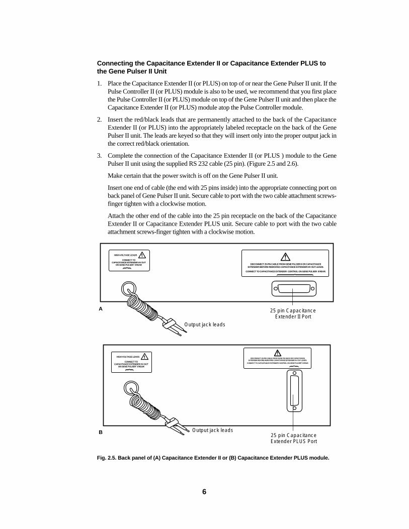
Connecting the Capacitance Extender II or Capacitance Extender PLUS tothe Gene Pulser II Unit
1. Place the Capacitance Extender II (or PLUS) on top of or near the Gene Pulser II unit. If thePulse Controller II (or PLUS) module is also to be used, we recommend that you first placethe Pulse Controller II (or PLUS) module on top of the Gene Pulser II unit and then place theCapacitance Extender II (or PLUS) module atop the Pulse Controller module.
2. Insert the red/black leads that are permanently attached to the back of the CapacitanceExtender II (or PLUS) into the appropriately labeled receptacle on the back of the GenePulser II unit. The leads are keyed so that they will insert only into the proper output jack inthe correct red/black orientation.
3. Complete the connection of the Capacitance Extender II (or PLUS ) module to the GenePulser II unit using the supplied RS 232 cable (25 pin). (Figure 2.5 and 2.6).
Make certain that the power switch is off on the Gene Pulser II unit.
Insert one end of cable (the end with 25 pins inside) into the appropriate connecting port onback panel of Gene Pulser II unit. Secure cable to port with the two cable attachment screws-finger tighten with a clockwise motion.
Attach the other end of the cable into the 25 pin receptacle on the back of the CapacitanceExtender II or Capacitance Extender PLUS unit. Secure cable to port with the two cableattachment screws-finger tighten with a clockwise motion.
Fig. 2.5. Back panel of (A) Capacitance Extender II or (B) Capacitance Extender PLUS module.
DISCONNECT 25-PIN CABLE FROM GENE PULSER II OR CAPACITANCEEXTENDER BEFORE REMOVING CAPACITANCE EXTENDER HV OUT LEADS.
CONNECT TO CAPACITANCE EXTENDER CONTROL ON GENE PULSER® II REAR.
HIGH-VOLTAGE LEADS
CONNECT TOCAPACITANCE EXTENDER HV OUT
ON GENE PULSER® II REAR
DISCONNECT 25-PIN CABLE FROM GENE PULSER II OR CAPACITANCEEXTENDER BEFORE REMOVING CAPACITANCE EXTENDER HV OUT LEADS.
CONNECT TO CAPACITANCE EXTENDER CONTROL ON GENE PULSER II REAR.
HIGH-VOLTAGE LEADS
CONNECT TOCAPACITANCE EXTENDER HV OUT
ON GENE PULSER® II REAR
6
Output jack leads
A 25 pin CapacitanceExtender II Port
Output jack leads B 25 pin CapacitanceExtender PLUS Port
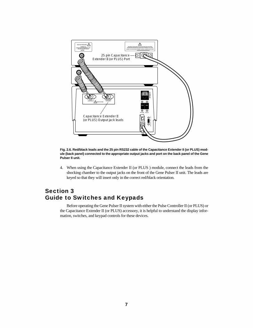
Fig. 2.6. Red/black leads and the 25 pin RS232 cable of the Capacitance Extender II (or PLUS) mod-ule (back panel) connected to the appropriate output jacks and port on the back panel of the GenePulser II unit.
4. When using the Capacitance Extender II (or PLUS ) module, connect the leads from theshocking chamber to the output jacks on the front of the Gene Pulser II unit. The leads arekeyed so that they will insert only in the correct red/black orientation.
Section 3Guide to Switches and Keypads
Before operating the Gene Pulser II system with either the Pulse Controller II (or PLUS) orthe Capacitance Extender II (or PLUS) accessory, it is helpful to understand the display infor-mation, switches, and keypad controls for these devices.
HIGH-VOLTAGE
CAPACITANCEEXTENDER
VOLTAGE SELECT
PULSECONTROLLER
DISCONNECT 25-PIN CABLE FROM GENE PULSER II OR CAPACITANCEEXTENDER BEFORE REMOVING CAPACITANCE EXTENDER HV OUT LEADS.
CONNECT TO CAPACITANCE EXTENDER CONTROL ON GENE PULSER II REAR.
POWER
TO
PRINTER
HIGH-VOLTAGE LEADS
CONNECT TOCAPACITANCE EXTENDER HV OUT
ON GENE PULSER® II REAR
7
Capacitance Extender II (or PLUS) Output jack leads
25 pin CapacitanceExtender II (or PLUS) Port
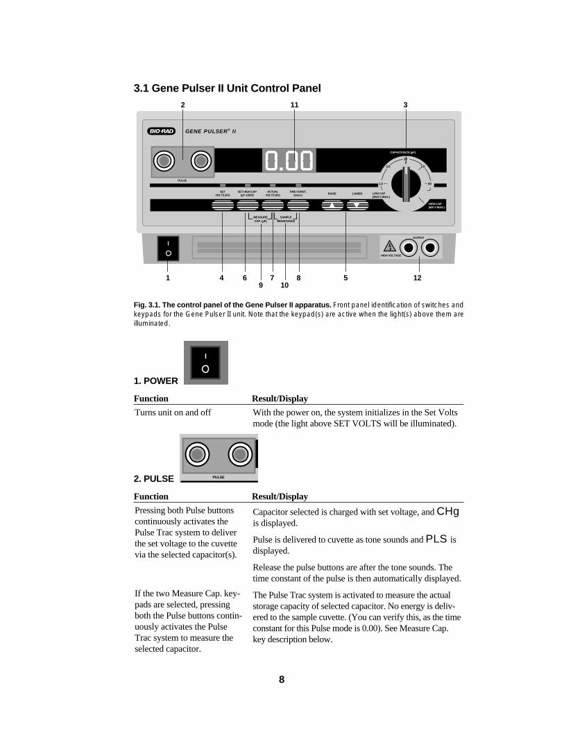
3.1 Gene Pulser II Unit Control Panel
Fig. 3.1. The control panel of the Gene Pulser II apparatus. Front panel identification of switches andkeypads for the Gene Pulser II unit. Note that the keypad(s) are active when the light(s) above them areilluminated.
1. POWER
Function Result/Display
2. PULSE
Function Result/Display
Capacitor selected is charged with set voltage, and CHgis displayed.
Pulse is delivered to cuvette as tone sounds and PLS isdisplayed.
Release the pulse buttons are after the tone sounds. Thetime constant of the pulse is then automatically displayed.
The Pulse Trac system is activated to measure the actualstorage capacity of selected capacitor. No energy is deliv-ered to the sample cuvette. (You can verify this, as the timeconstant for this Pulse mode is 0.00). See Measure Cap.key description below.
Pressing both Pulse buttonscontinuously activates thePulse Trac system to deliverthe set voltage to the cuvettevia the selected capacitor(s).
If the two Measure Cap. key-pads are selected, pressingboth the Pulse buttons contin-uously activates the PulseTrac system to measure theselected capacitor.
PULSE
With the power on, the system initializes in the Set Voltsmode (the light above SET VOLTS will be illuminated).
Turns unit on and off
HIGH VOLTAGE
OUTPUT
PULSE
SETVOLTS (kV)
ACTUALVOLTS (kV)
TIME CONST.(msec) RAISE LOWER
HIGH CAP(500 V MAX.)
SET HIGH CAP(µF x1000)
MEASURECAP. (µF)
GENE PULSER® II
CAPACITANCE (µF)
LOW CAP(2500 V MAX.)
10
1.0 50
3.0 2.5
SAMPLERESISTANCE
8
1 12
11
109876 54
32
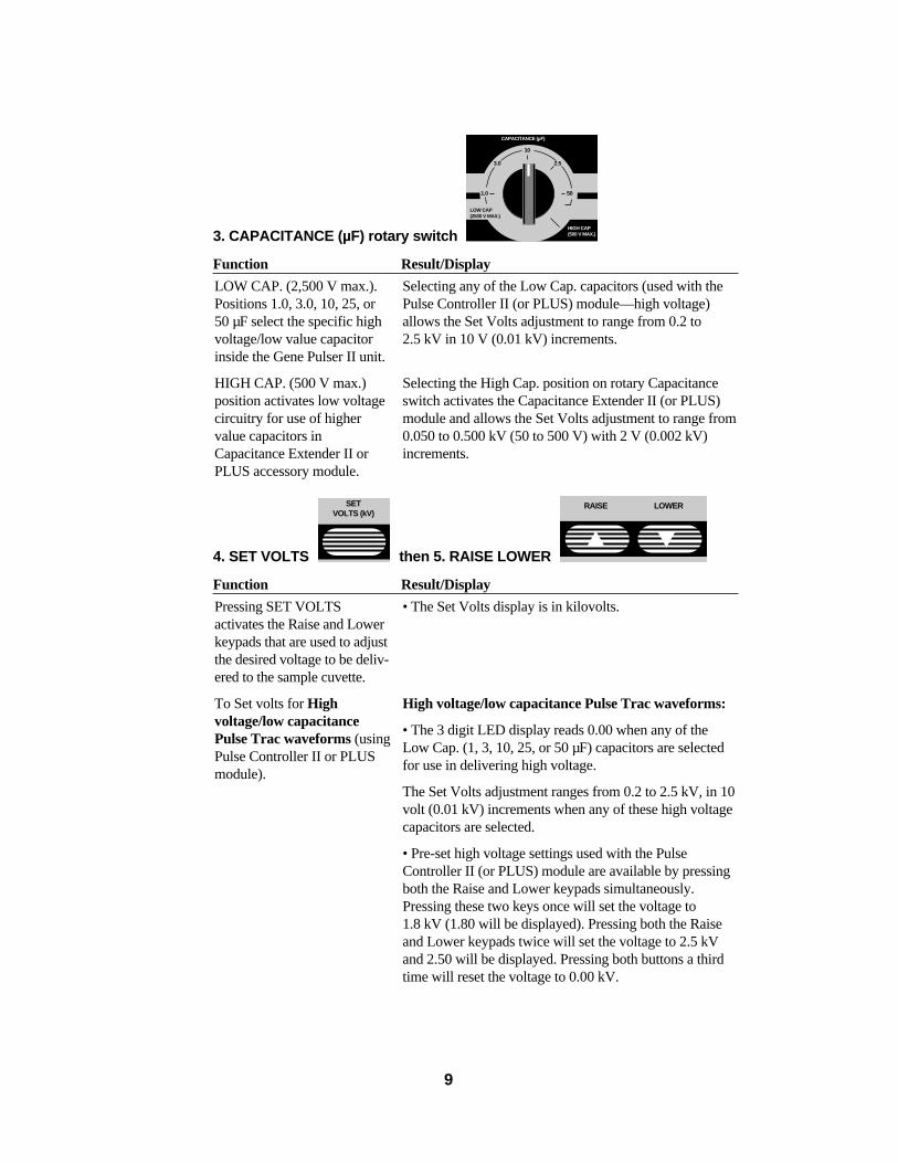
3. CAPACITANCE (µF) rotary switch
Function Result/Display
4. SET VOLTS then 5. RAISE LOWER
Function Result/Display
• The Set Volts display is in kilovolts.
High voltage/low capacitance Pulse Trac waveforms:
• The 3 digit LED display reads 0.00 when any of theLow Cap. (1, 3, 10, 25, or 50 µF) capacitors are selectedfor use in delivering high voltage.
The Set Volts adjustment ranges from 0.2 to 2.5 kV, in 10volt (0.01 kV) increments when any of these high voltagecapacitors are selected.
• Pre-set high voltage settings used with the PulseController II (or PLUS) module are available by pressingboth the Raise and Lower keypads simultaneously.Pressing these two keys once will set the voltage to1.8 kV (1.80 will be displayed). Pressing both the Raiseand Lower keypads twice will set the voltage to 2.5 kVand 2.50 will be displayed. Pressing both buttons a thirdtime will reset the voltage to 0.00 kV.
Pressing SET VOLTSactivates the Raise and Lowerkeypads that are used to adjustthe desired voltage to be deliv-ered to the sample cuvette.
To Set volts for Highvoltage/low capacitancePulse Trac waveforms (usingPulse Controller II or PLUSmodule).
RAISE LOWERSETVOLTS (kV)
Selecting any of the Low Cap. capacitors (used with thePulse Controller II (or PLUS) module—high voltage)allows the Set Volts adjustment to range from 0.2 to2.5 kV in 10 V (0.01 kV) increments.
Selecting the High Cap. position on rotary Capacitanceswitch activates the Capacitance Extender II (or PLUS)module and allows the Set Volts adjustment to range from0.050 to 0.500 kV (50 to 500 V) with 2 V (0.002 kV)increments.
LOW CAP. (2,500 V max.).Positions 1.0, 3.0, 10, 25, or50 µF select the specific highvoltage/low value capacitorinside the Gene Pulser II unit.
HIGH CAP. (500 V max.)position activates low voltagecircuitry for use of highervalue capacitors inCapacitance Extender II orPLUS accessory module.
HIGH CAP(500 V MAX.)
CAPACITANCE (µF)
LOW CAP(2500 V MAX.)
10
1.0 50
3.0 2.5
9
Function Result/Display
6. SET HIGH CAP. (µF x 1,000)
then 5. RAISE/LOWER
Function Result/Display
When the power is turned on, the capacitor selected is0.025 (x 1,000) or 25 µF. The display reads .025.
Adjustments can be made in 25 µF increments using theRaise or Lower buttons. Choose capacitors between 25 to1,075 µF [displayed as .025 to 1.07 (x 1,000) µF] in theCapacitance Extender II module or 25 to 3,275 µF [dis-played as .025 to 3.27 (x 1,000) µF] in the CapacitanceExtender PLUS module.
The LED abbreviates the display of capacitors larger than975 µF as 1.00=1.000, 1.02 =1.025, 1.05 =1.050, 1.07 =1.075 (x 1,000) µF, etc., but actual capacitor valuesare as cited.
Dashes (– – –) will appear on LED display if Capacitancerotary switch is not set on High Cap. position.
If the Capacitance Extender II (or PLUS) module is notconnected to the Gene Pulser II unit, no will be dis-played.
Allows Raise and Lowerkeypads to adjust the selec-tion of capacitors of theCapacitance Extender II (or PLUS) module.
RAISE LOWER
SET HIGH CAP(µF x1000)
Low voltage/high capacitance Pulse Trac waveforms:
The 3 digit LED display reads .000 if the High Cap. posi-tion is selected.
The Set Volts adjustment ranges from 0.050 to 0.500 kV(50 to 500 V) with 2 V (0.002 kV) increments when HighCap. position is selected on rotary Capacitance switch.[Note: If the voltage is set at 0.00, the display will readno if the pulse buttons are pressed].
Pre-set low voltage settings used with the CapacitanceExtender II (or PLUS) module are available by pressingboth the Raise and Lower keypads simultaneously.Pressing these two keys once will set the voltageto 0.360 kV (and 0.360 will be displayed). Pressing boththe Raise and Lower keypads twice will set the voltage to0.500 kV and .500 will be displayed. Pressing both but-tons a third time will reset the voltage to .000 kV.
To Set volts for Lowvoltage/high capacitancePulse Trac waveforms (usingCapacitance Extender II orPLUS module).
10
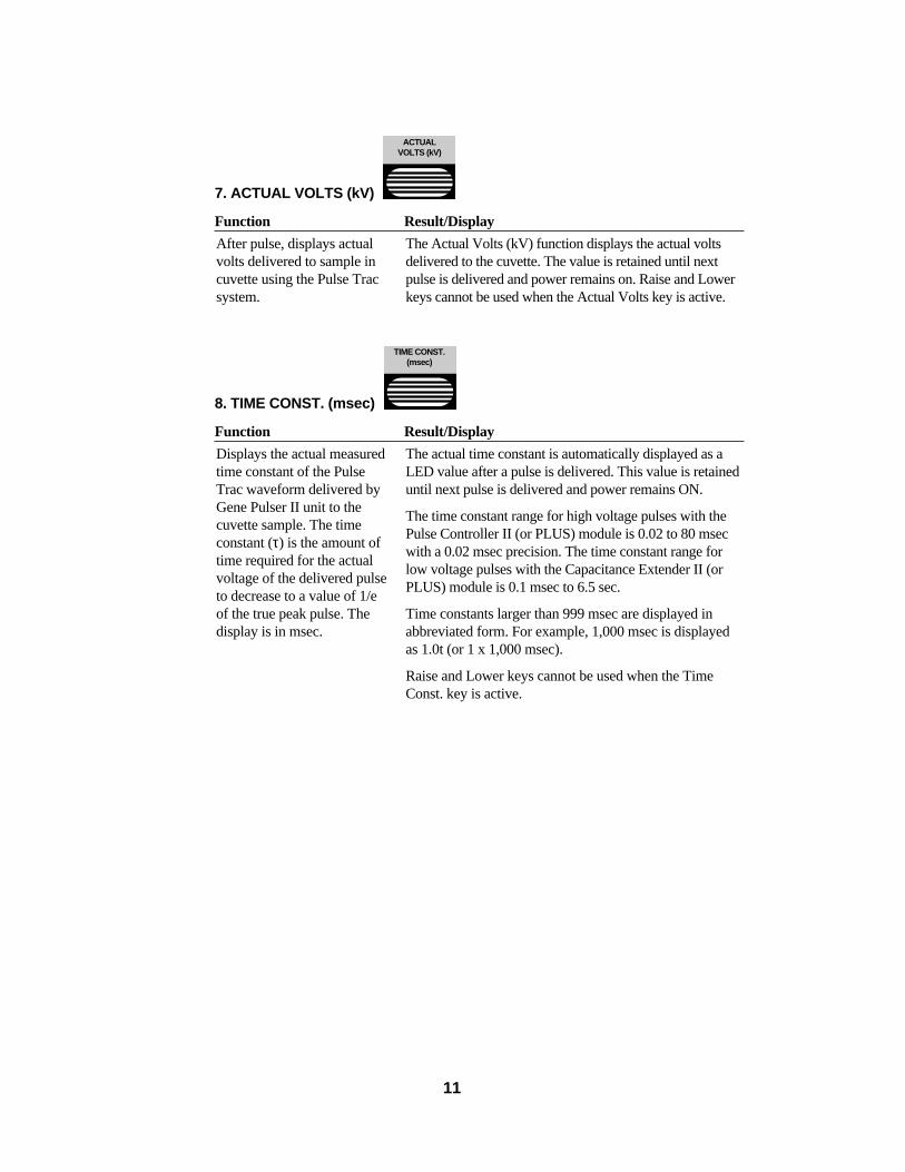
7. ACTUAL VOLTS (kV)
Function Result/Display
8. TIME CONST. (msec)
Function Result/Display
The actual time constant is automatically displayed as aLED value after a pulse is delivered. This value is retaineduntil next pulse is delivered and power remains ON.
The time constant range for high voltage pulses with thePulse Controller II (or PLUS) module is 0.02 to 80 msecwith a 0.02 msec precision. The time constant range forlow voltage pulses with the Capacitance Extender II (orPLUS) module is 0.1 msec to 6.5 sec.
Time constants larger than 999 msec are displayed inabbreviated form. For example, 1,000 msec is displayedas 1.0t (or 1 x 1,000 msec).
Raise and Lower keys cannot be used when the TimeConst. key is active.
Displays the actual measuredtime constant of the PulseTrac waveform delivered byGene Pulser II unit to thecuvette sample. The timeconstant (τ) is the amount oftime required for the actualvoltage of the delivered pulseto decrease to a value of 1/eof the true peak pulse. Thedisplay is in msec.
TIME CONST.(msec)
The Actual Volts (kV) function displays the actual voltsdelivered to the cuvette. The value is retained until nextpulse is delivered and power remains on. Raise and Lowerkeys cannot be used when the Actual Volts key is active.
After pulse, displays actualvolts delivered to sample incuvette using the Pulse Tracsystem.
ACTUALVOLTS (kV)
11
12
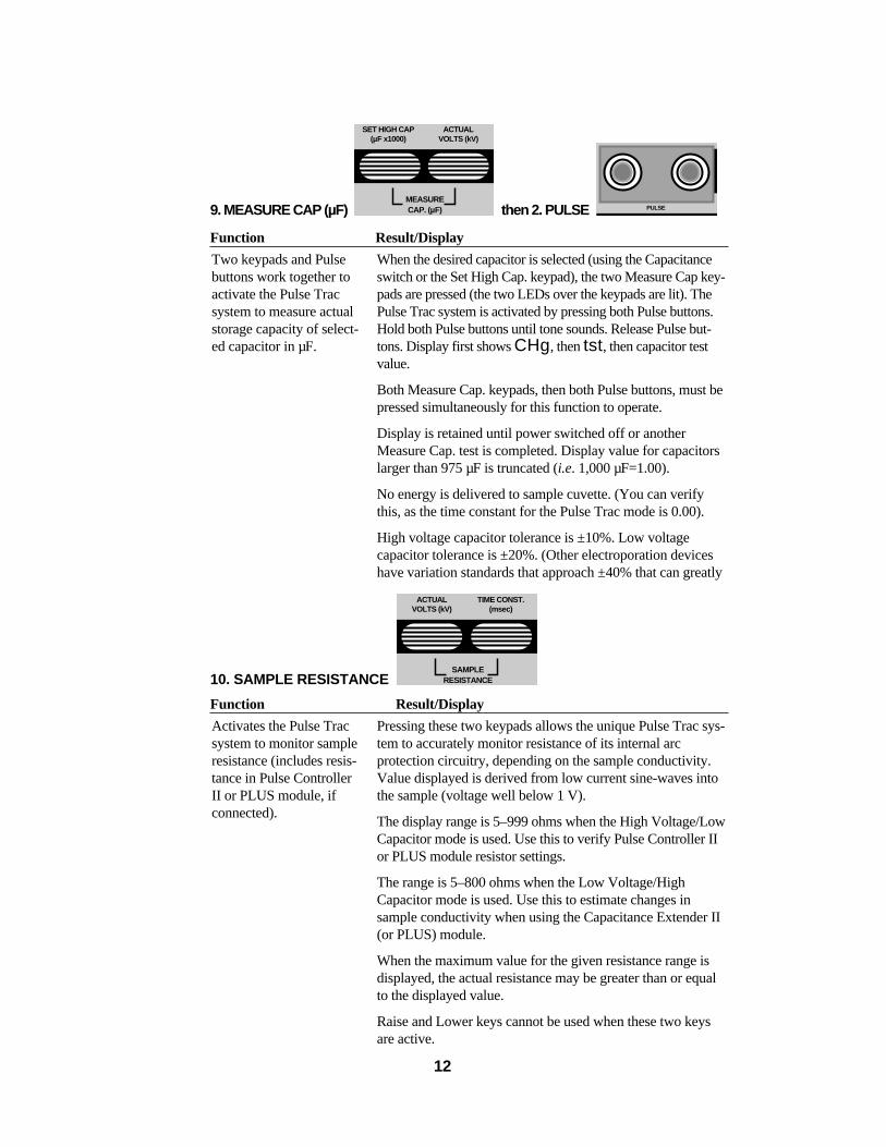
9. MEASURE CAP (µF) then 2. PULSE
Function Result/Display
10. SAMPLE RESISTANCE
Function Result/Display
Pressing these two keypads allows the unique Pulse Trac sys-tem to accurately monitor resistance of its internal arcprotection circuitry, depending on the sample conductivity.Value displayed is derived from low current sine-waves intothe sample (voltage well below 1 V).
The display range is 5–999 ohms when the High Voltage/LowCapacitor mode is used. Use this to verify Pulse Controller IIor PLUS module resistor settings.
The range is 5–800 ohms when the Low Voltage/HighCapacitor mode is used. Use this to estimate changes insample conductivity when using the Capacitance Extender II(or PLUS) module.
When the maximum value for the given resistance range isdisplayed, the actual resistance may be greater than or equalto the displayed value.
Raise and Lower keys cannot be used when these two keysare active.
Activates the Pulse Tracsystem to monitor sampleresistance (includes resis-tance in Pulse ControllerII or PLUS module, ifconnected).
ACTUALVOLTS (kV)
TIME CONST.(msec)
SAMPLERESISTANCE
When the desired capacitor is selected (using the Capacitanceswitch or the Set High Cap. keypad), the two Measure Cap key-pads are pressed (the two LEDs over the keypads are lit). ThePulse Trac system is activated by pressing both Pulse buttons.Hold both Pulse buttons until tone sounds. Release Pulse but-tons. Display first shows CHg, then tst, then capacitor testvalue.
Both Measure Cap. keypads, then both Pulse buttons, must bepressed simultaneously for this function to operate.
Display is retained until power switched off or anotherMeasure Cap. test is completed. Display value for capacitorslarger than 975 µF is truncated (i.e. 1,000 µF=1.00).
No energy is delivered to sample cuvette. (You can verifythis, as the time constant for the Pulse Trac mode is 0.00).
High voltage capacitor tolerance is ±10%. Low voltagecapacitor tolerance is ±20%. (Other electroporation deviceshave variation standards that approach ±40% that can greatly
Two keypads and Pulsebuttons work together toactivate the Pulse Tracsystem to measure actualstorage capacity of select-ed capacitor in µF.
PULSE
ACTUALVOLTS (kV)
SET HIGH CAP(µF x1000)
MEASURECAP. (µF)
11. LED
Function Result/Display
12. Shocking Chamber Output Jack
Function Result/Display
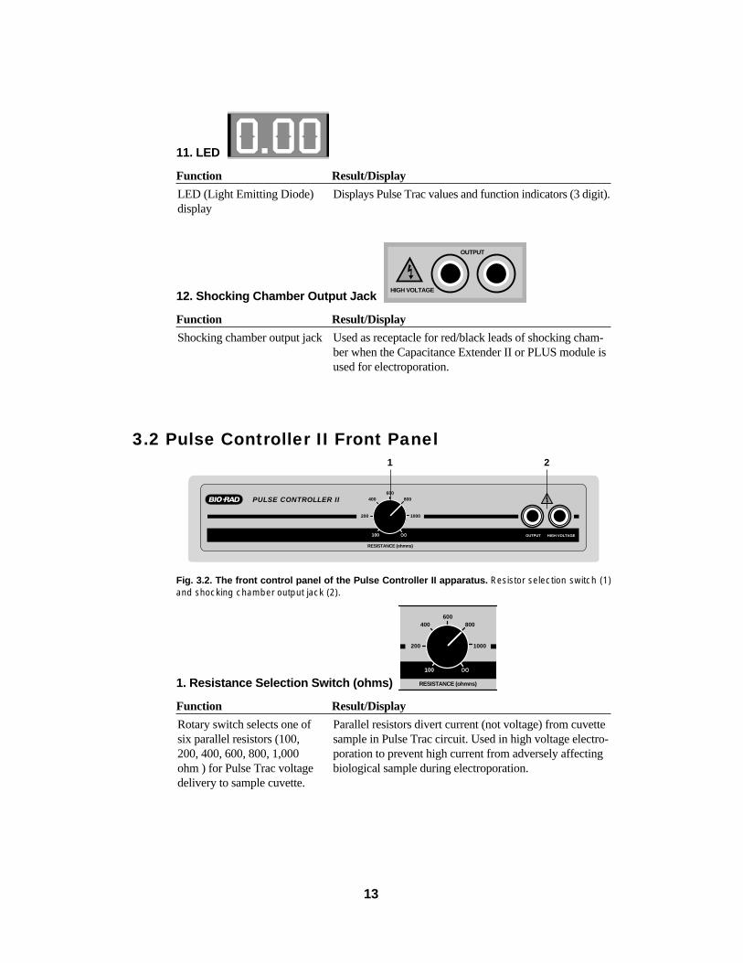
3.2 Pulse Controller II Front Panel
Fig. 3.2. The front control panel of the Pulse Controller II apparatus. Resistor selection switch (1)and shocking chamber output jack (2).
1. Resistance Selection Switch (ohms)
Function Result/Display
Parallel resistors divert current (not voltage) from cuvettesample in Pulse Trac circuit. Used in high voltage electro-poration to prevent high current from adversely affectingbiological sample during electroporation.
Rotary switch selects one ofsix parallel resistors (100,200, 400, 600, 800, 1,000ohm ) for Pulse Trac voltagedelivery to sample cuvette.
400 800600
200
RESISTANCE (ohmns)
1000
100
PULSE CONTROLLER II 400 800600
200
RESISTANCE (ohmns)
1000
100 OUTPUT HIGH VOLTAGE
Used as receptacle for red/black leads of shocking cham-ber when the Capacitance Extender II or PLUS module isused for electroporation.
Shocking chamber output jack
HIGH VOLTAGE
OUTPUT
Displays Pulse Trac values and function indicators (3 digit).LED (Light Emitting Diode)display
13
1 2
Function Result/Display
2. Shocking chamber output jack
Function Result/Display
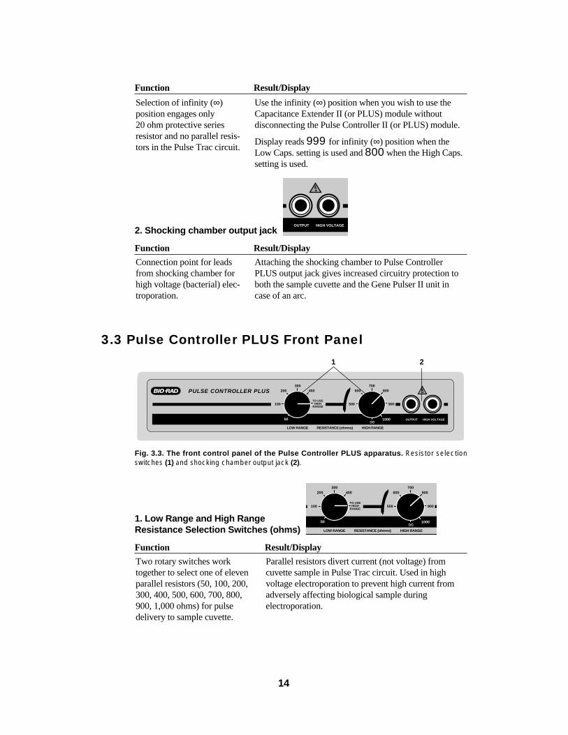
3.3 Pulse Controller PLUS Front Panel
Fig. 3.3. The front control panel of the Pulse Controller PLUS apparatus. Resistor selection switches (1) and shocking chamber output jack (2).
1. Low Range and High Range Resistance Selection Switches (ohms)
Function Result/Display
Parallel resistors divert current (not voltage) fromcuvette sample in Pulse Trac circuit. Used in highvoltage electroporation to prevent high current fromadversely affecting biological sample duringelectroporation.
Two rotary switches worktogether to select one of elevenparallel resistors (50, 100, 200,300, 400, 500, 600, 700, 800,900, 1,000 ohms) for pulsedelivery to sample cuvette.
200 400300
100
LOW RANGE RESISTANCE (ohmns)
TO USEHIGH
RANGE
50
600 800700
500 900
HIGH RANGE
1000
PULSE CONTROLLER PLUS 200 400300
100
LOW RANGE RESISTANCE (ohmns)
TO USEHIGH
RANGE
50
600 800700
500 900
HIGH RANGE
1000 OUTPUT HIGH VOLTAGE
Attaching the shocking chamber to Pulse ControllerPLUS output jack gives increased circuitry protection toboth the sample cuvette and the Gene Pulser II unit incase of an arc.
Connection point for leadsfrom shocking chamber forhigh voltage (bacterial) elec-troporation.
OUTPUT HIGH VOLTAGE
Use the infinity (∞) position when you wish to use theCapacitance Extender II (or PLUS) module withoutdisconnecting the Pulse Controller II (or PLUS) module.
Display reads 999 for infinity (∞) position when theLow Caps. setting is used and 800 when the High Caps.setting is used.
Selection of infinity (∞)position engages only20 ohm protective seriesresistor and no parallel resis-tors in the Pulse Trac circuit.
14
1 2
Function Result/Display
2. Shocking chamber output jack
Function Result/Display
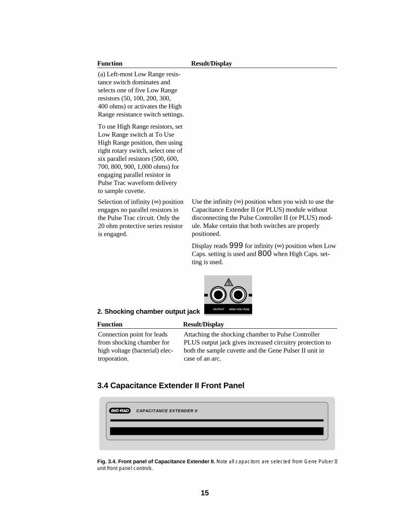
3.4 Capacitance Extender II Front Panel
Fig. 3.4. Front panel of Capacitance Extender II. Note all capacitors are selected from Gene Pulser IIunit front panel controls.
CAPACITANCE EXTENDER II
Attaching the shocking chamber to Pulse ControllerPLUS output jack gives increased circuitry protection toboth the sample cuvette and the Gene Pulser II unit incase of an arc.
Connection point for leadsfrom shocking chamber forhigh voltage (bacterial) elec-troporation.
OUTPUT HIGH VOLTAGE
Use the infinity (∞) position when you wish to use theCapacitance Extender II (or PLUS) module withoutdisconnecting the Pulse Controller II (or PLUS) mod-ule. Make certain that both switches are properlypositioned.
Display reads 999 for infinity (∞) position when LowCaps. setting is used and 800 when High Caps. set-ting is used.
Selection of infinity (∞) positionengages no parallel resistors inthe Pulse Trac circuit. Only the20 ohm protective series resistoris engaged.
(a) Left-most Low Range resis-tance switch dominates andselects one of five Low Rangeresistors (50, 100, 200, 300,400 ohms) or activates the HighRange resistance switch settings.
To use High Range resistors, setLow Range switch at To UseHigh Range position, then usingright rotary switch, select one ofsix parallel resistors (500, 600,700, 800, 900, 1,000 ohms) forengaging parallel resistor inPulse Trac waveform delivery to sample cuvette.
15
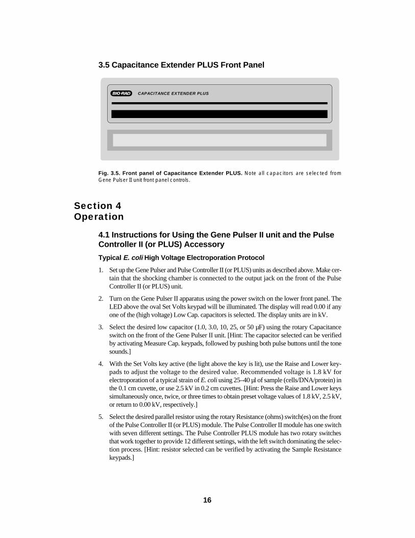
3.5 Capacitance Extender PLUS Front Panel
Fig. 3.5. Front panel of Capacitance Extender PLUS. Note all capacitors are selected from Gene Pulser II unit front panel controls.
Section 4Operation
4.1 Instructions for Using the Gene Pulser II unit and the PulseController II (or PLUS) Accessory
Typical E. coli High Voltage Electroporation Protocol
1. Set up the Gene Pulser and Pulse Controller II (or PLUS) units as described above. Make cer-tain that the shocking chamber is connected to the output jack on the front of the PulseController II (or PLUS) unit.
2. Turn on the Gene Pulser II apparatus using the power switch on the lower front panel. TheLED above the oval Set Volts keypad will be illuminated. The display will read 0.00 if anyone of the (high voltage) Low Cap. capacitors is selected. The display units are in kV.
3. Select the desired low capacitor (1.0, 3.0, 10, 25, or 50 µF) using the rotary Capacitanceswitch on the front of the Gene Pulser II unit. [Hint: The capacitor selected can be verifiedby activating Measure Cap. keypads, followed by pushing both pulse buttons until the tonesounds.]
4. With the Set Volts key active (the light above the key is lit), use the Raise and Lower key-pads to adjust the voltage to the desired value. Recommended voltage is 1.8 kV forelectroporation of a typical strain of E. coli using 25–40 µl of sample (cells/DNA/protein) inthe 0.1 cm cuvette, or use 2.5 kV in 0.2 cm cuvettes. [Hint: Press the Raise and Lower keyssimultaneously once, twice, or three times to obtain preset voltage values of 1.8 kV, 2.5 kV,or return to 0.00 kV, respectively.]
5. Select the desired parallel resistor using the rotary Resistance (ohms) switch(es) on the frontof the Pulse Controller II (or PLUS) module. The Pulse Controller II module has one switchwith seven different settings. The Pulse Controller PLUS module has two rotary switchesthat work together to provide 12 different settings, with the left switch dominating the selec-tion process. [Hint: resistor selected can be verified by activating the Sample Resistancekeypads.]
CAPACITANCE EXTENDER PLUS
16

6. Place the cell/DNA/protein suspension at the bottom of the chilled electroporation cuvettebetween the aluminum plates. Use up to 0.4 ml (400 µl) of solution in a 0.2 cm cuvette andup to 0.08 ml (80 µl) in a 0.1 cm cuvette.
7. Insert the cuvette into the cuvette slide. Push the slide into the shocking chamber until thecuvette makes firm contact with the shocking chamber electrodes.
8. Press both Pulse buttons simultaneously and hold until tone sounds (CHg will flash andPLS will be displayed during this process). Release both Pulse buttons once tone sounds.The time constant is automatically displayed after every pulse.
9. Remove the cuvette from the chamber, immediately add the appropriate outgrowth medi-um to the cuvette, and quickly, but gently, resuspend the cells with a transfer pipette.
10. Transfer the cell suspension to a sterile culture tube and incubate under the appropriate out-growth conditions.
11. Check and record the pulse parameters. Time constant is automatically displayed after everypulse. Check actual volts delivered.
4.2 Instructions for Using the Gene Pulser II unit with theCapacitance Extender II (or PLUS ) Accessory Module
Typical Low Voltage Electroporation (Mammalian Cells) Protocol
1. Set up the Gene Pulser and Capacitance Extender II (or PLUS) units as described above.Make certain that the shocking chamber is connected to the output jack on the front of theGene Pulser II unit. [Hint: You can keep the Pulse Controller II (or PLUS) connected to theGene Pulser II unit when using the Capacitance Extender II (or PLUS) module. Simply setthe Pulse Controller II (or PLUS) module to the infinity (∞) position. For the Pulse ControllerPLUS module, make certain that both switches are properly positioned].
2. Turn on the Gene Pulser II apparatus using the power switch on the lower front panel. TheLED above the oval Set Volts keypad will be illuminated. The display will read .000 if the(low voltage) High Cap. position is selected on the Capacitance switch (on the front panel ofthe Gene Pulser II unit). The display units are in kV.
3. Verify that the rotary Capacitance switch on the front of the Gene Pulser II unit is set to theHigh Cap. position (fully clockwise). Select the desired capacitor by pressing the Set HighCap (µF x 1,000) keypad and then adjust capacitor value by using the Raise and Lower key-pads.
4. With the Set Volts key active (the light above the key is lit), use the Raise and Lower key-pads to adjust the voltage to the desired value. Suggested voltage of 0.2 to 0.4 kV, using400–800 µl (cells/DNA/protein) is recommended for electroporation of most mammaliancells in the 0.4 cm cuvette. [Hint: press the Raise and Lower keys simultaneously once, twice,or three times to obtain preset voltage values of 0.360 kV, 0.500 kV, or return to 0.00 kV,respectively. Capacitor selected can be verified by activating Measure Cap. keypads, fol-lowed by pushing both pulse buttons.]
5. Place the cell/DNA/protein suspension at the bottom of the electroporation cuvette betweenthe aluminum plates (typically at room temperature). Use up to 0.8 ml (800 µl) of solution inthe 0.4 cm cuvette.
6. Insert the cuvette into the cuvette slide. Push the slide into the shocking chamber until thecuvette makes firm contact with the chamber electrodes.
17
7. Press both Pulse buttons simultaneously and hold until tone sounds (CHg will flash andPLS will be displayed during this process). Release both Pulse buttons when the tonesounds. The time constant is automatically displayed after every pulse. [Hint: large capaci-tors may require several seconds to safely charge. Do not release PULSE buttons until tonesounds.]
8. Remove the cuvette from the chamber and immediately add the appropriate outgrowth medi-um to the cuvette and quickly but gently resuspend the cells with a transfer pipette.
9. Transfer the cell suspension to a sterile container and incubate under the appropriate outgrowth conditions.
10. Check and record the pulse parameters. Time constant is automatically displayed after everypulse. Check actual volts delivered, and sample resistance.
Section 5The Pulse Trac System
5.1 Pulse Trac System DescriptionThe Pulse Trac system monitors and adjusts for the total resistance and capacitance of the
complete circuit, including the sample in the cuvette. Sample resistance depends on both its con-ductivity and its cross-sectional area in the cuvette. The unique Pulse Trac circuitry monitorsthe resistance of the sample and delivers the desired voltage regardless of sample volume or con-ductivity. An advantage of the Pulse Trac system is that the measured τ for every pulse is basedon the actual voltage delivered to the cuvette sample, including the entire electrical circuit andsample resistance; not on some theoretical calculation based on the settings you have chosenon the instrument or the overall pulse decay time. When you are optimizing electroporation withthe Pulse Trac system, the electrical variables are controlled with exacting precision so thatyour results reflect only the biological variables in your experimental design.
Minimize any variation in the electrical circuitry between experiments with the Pulse Tracdiagnostic algorithm (see Section 5.2 for operation instructions). This test algorithm examinesthe complete electrical circuit and electronically selects the right combination of capacitors todeliver the most accurate and reproducible pulse for optimal and consistent electroporation overthe lifetime of the unit.
5.2 Pulse Trac Diagnostic AlgorithmThis test algorithm tests and selects the optimal capacitor circuit of the Gene Pulser II unit
and the Capacitance Extender II or PLUS module in the range of 100–1,075 µF. This is the keybank of electronically selected capacitors used in low voltage /high capacitance precision pulsedelivery. When completed, this test algorithm is active as long as the power to the unit is on. Thetest algorithm tightens the already rigorous capacitor tolerance from ±20% to ±10% (other unitdesigns can have a capacitor variance as high as ±40%).
Note: the high voltage capacitors in the Gene Pulser II unit are not part of this system, asthey are pre-selected to the same 10% tolerance that this test algorithm provides.
To activate the Pulse Trac test algorithm, use Measure Cap and Pulse as follows (test requires~30 seconds to complete).
18
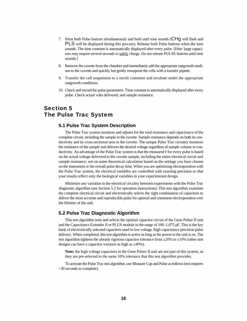
9. MEASURE CAP (µF) then 2. PULSE
Function Result/Display
The two Measure Cap keypads are pressed (the two LEDsover the keypads are lit) and held continuously for 4 secondsuntil ALg is displayed. Release Measure Cap. keypads.
The PULSE TRAC algorithm is activated by pressing bothPulse buttons. Hold both Pulse buttons continuously(about 25 seconds) until a long tone sounds and dnE is displayed. Display characters will vary as test progressesthrough the circuit. Release Pulse buttons.
After tone sounds and Pulse buttons are released, dnE(done) will flash and the display will appear 00.0.The Measure Cap. keypads are still active (lights abovekeypads are lit).
When the test has been completed, select any of the lowvoltage/ High (value) capacitors using the Set High Cap.keypad and the Raise /Lower keypads as described inSection 3.1. Any capacitor now selected (100–1,075 µFrange) will be verified as a precision capacitor with theflashed Prc CAP display.
Low voltage capacitor tolerance is now ±10%. High voltagecapacitor tolerance is already ±10%. (Other electroporationdevices have variation standards that approach ±40% thatcan greatly hinder consistent electroporation results.)
The test algorithm is locked on until the power to the unitis turned off. To discontinue this test after the ALg hasbeen selected, turn the unit power off.
No energy is delivered to sample cuvette during this test.You can verify this, as the time constant for this PulseTrac mode is 000 and the Actual Volts (kV) deliveredvalue is .000.
Two Measure Cap. keypadsand Pulse buttons worktogether to activate the PulseTrac test algorithm to recali-brate the low voltagecapacitors between 100–1,075µF.
Test algorithm can be usedwhen the CapacitanceExtender II or PLUS moduleis properly connected to theGene Pulser II unit and thecapacitor selection switch isset in the High Cap. position.
PULSE
ACTUALVOLTS (kV)
SET HIGH CAP(µF x1000)
MEASURECAP. (µF)
19
Section 6Instrument Diagnostics and Troubleshooting
Problem Likely Cause
1. Display does not light when unit is turned on.
2. Apparatus displays nowhen pulse button are pressed.
3. When the pulse buttons are pressed, the display continues to flash CHg, but the tone does not sound.
4. Arcing in the cuvette Arcing in the cuvette is usually caused by a sample mediumthat is too conductive. The limit of conductivity depends onthe voltage, electrode gap, and sample volume.
When using the Pulse Controller II or PLUS module, arcsoccasionally occur in high voltage delivery (typical E. coliprotocol) if the sample is 10 meq or higher. Causes ofexcessive conductivity include:
1. Washing and resuspending cells in a buffer that is toohigh in ionic strength.
2. Insufficient washing of cells; salts of growth medium arenot removed.
3. Lysed cells in the preparation.; cell contents contribute toconductivity.
4. DNA solution too high in salt content. Ligation mixture,or CsCl carry-over during DNA purification. DiluteDNA 1/100 with ultra-pure water or use Prep-A-Gene®
purification matrix.
5. Electroporation of cells above 0 °C (cell lysis).
No pulse delivery.
Pulse buttons not depressed long enough. Large capacitorsor conditions that generate long time constants require alonger charging time (several seconds) to maintain safepulse delivery. The pulse buttons should not be releaseduntil the tone sounds.
Only one pulse button depressed. Both of the red pulse but-tons must be pressed continuously until the tone sounds forpulse delivery.
Sample resistance too high. Lower sample resistance (e.g.,increase ionic strength of the media). Use the Gene PulserII unit with the Pulse Controller II or PLUS module forpulse delivery into high resistance samples.
Voltage set at zero. Press Set Volts keypad. Adjust voltagewith Raise and Lower keypads to desired voltage.
Capacitance (µF) select switch set on High Cap., butCapacitance Extender II or PLUS module is not properlyconnected to Gene Pulser II unit. Check leads as connectedto rear of Gene Pulser II unit and RS232 cable connection.
Power is not supplied to electronics. Check power cord andwall outlet power source. Check that power switch is on.Check/replace fuse.
20
Section 7Specifications and Product Information
7.1 System Specifications
Gene Pulser II SystemInput voltage 100/120 V RMS, 50/60 Hz
220/240 V RMS, 50/60 HzInput current 15 amp RMSMaximum output voltage and current 2,500 V at 125 amp peak (normal load);
limited to 1,500 A during arc.Output waveform Pulse Trac exponential decay with RC time con-
stant dependent on sample and capacitorselected
Output voltage adjustment 50–2,500 V range (depending on the capacitor)with 10 V adjustment precision for the high voltagerange and 2 V for the low-voltage range(50–500 V).
Ambient operating environment Temperature 0–35 °CHumidity 0–95% without condensation
Regulatory Passes requirements of IEC 1010. In addition, thesystem passes requirements for FCC, Class A.
Dimensions 34 x 31 x 19 cmWeight 10.41 kg
Pulse Controller II SystemSelectable resistance, ohms, (parallel) 100, 200, 400, 600, 800, 1,000, infinity ohms;
measured with Gene Pulser II apparatusDimensions 23 x 31 x 7.7 cmWeight 1.7 kg
Pulse Controller PLUS SystemSelectable resistance, ohms, (parallel) 50, 100, 200, 300, 400, 500, 600, 700, 800, 900,
1,000, infinity ohms; measured with Gene Pulser IIapparatus
Dimensions 23 x 31 x 7.7 cmWeight 1.87 kg
Capacitance Extender II SystemSelectable capacitors, µF 25 to 1,075 µF, in 25 µF increments; measured
with Gene Pulser II apparatusDimensions 23 x 31 x 9.7 cmWeight 2.57 kg
Capacitance Extender PLUS SystemSelectable capacitors, µF 25 to 3,275 µF, in 25 µF increments; measured
with Gene Pulser II apparatusDimensions 23 x 31 x 13.7 cmWeight 3.64 kg
21
7.2 Product InformationCatalog Number Product Description
165-2105 Gene Pulser II Apparatus, 100/120 V, 50/60 Hz; includes 1 shockingchamber, 15 sterile sample cuvettes (five 0.1 cm gap, five 0.2 cm gap andfive 0.4 cm gap), 1 cuvette rack
165-2106 Gene Pulser II Apparatus, 220/240 V, 50/60Hz; includes 1 shockingchamber, 15 sterile sample cuvettes (five 0.1 cm gap, five 0.2 cm gap andfive 0.4 cm gap), 1 cuvette rack
165-2107 Capacitance Extender II, 25–1075 µF range measured by Gene Pulser IIapparatus; includes integrated leads
165-2108 Capacitance Extender PLUS, 25–3,275 µF range measured by Gene Pulser IIapparatus; includes integrated leads
165-2109 Pulse Controller II, 100-1,000 ohm range, seven settings (100, 200, 400, 600,800, 1,000, infinity ohms); includes integrated leads
165-2110 Pulse Controller PLUS, 50–1,000 ohm range, twelve settings (50, 100, 200, 300,400, 500, 600, 700, 800, 900, 1,000, infinity ohms); includes integrated leads
165-2111 Gene Pulser II /E.coli Pulser™ shocking chamber
165-2095 Gene Pulser Cuvette Rack
165-2094 Gene Pulser Electroprotocols
165-2088 Gene Pulser Cuvettes, 0.4 cm electrode gap, package of 50, sterile
165-2086 Gene Pulser/E. coli Pulser Cuvettes, 0.2 cm electrode gap, package of 50,sterile
165-2089 Gene Pulser /E. coli Pulser Cuvettes, 0.1 cm electrode gap, package of 50,sterile
Appendix AReview of Electroporation Fundamentals
Electroporation is a physical process that transiently permeabilizes prokaryotic and eukary-otic cell membranes with an electrical pulse, thus permitting cell uptake of a wide variety ofbiological molecules. Electro-transformation provides the researcher with a valuable alterna-tive to chemical and other physical methods that may be ineffective or toxic when transformingcertain cell types.
22

How Electroporation WorksThe delivered pulse decays exponentially through time, and is defined by two pulse param-
eters, the initial field strength (kV/cm) and the time constant (τ). Both the field strength and thetime constant must be characterized for each cell type. You determine the field strength byselecting the voltage (kV) that is delivered across the cuvette electrode gap (cm). Generally, thelarger the cell, the lower the field strength required for efficient electroporation. The time con-stant, τ (msec) = resistance, R (ohms) x capacitance, C (microfarads), in the complete pulsecircuit is equivalent to the amount of time it takes for the initial peak voltage (V0) to drop to thevalue of V0/e; this is a decay time for the pulse to decrease to a value of about 37% of V0 (Fig. A.1.).
Fig. A.1. Electroporation delivers an electrical pulse to permeabilize cell membranes for the uptakeof biological molecules. The pulse decays exponentially over a short time (msec). The time constant,τ (msec) is the time required for the initial voltage (V0) to decay to 37% of V0. Also, the time constant,(τ, msec) = resistance, R (ohms) x capacitance, C (microfarads) in the complete pulse circuit, (τ = R x C).
Key Optimization Concepts Electroporation must be optimized for each cell type, since the pulse must penetrate cells that
differ in diameter, membrane/cell wall composition, and in the medium needed to support mem-brane/cell wall integrity during electroporation. Key parameters for optimal electroporation are:
The time constant (τ)
This is an essential parameter because it precisely describes each pulse delivered to your sam-ple. τ is equivalent to the amount of time it takes for the initial peak voltage (V0) to drop to thevalue of V0/e; this is a decay time for the pulse to decrease to a value of about 37% of V0, (FigureA.1). The time constant for each pulse is also the product of the total resistance and capacitanceof the pulse circuit [τ = R x C ].
The resistance and capacitance of the pulse circuit will directly influence the rate of decay[τ, (msec)] of the exponential pulse waveform that is delivered to the sample.
23
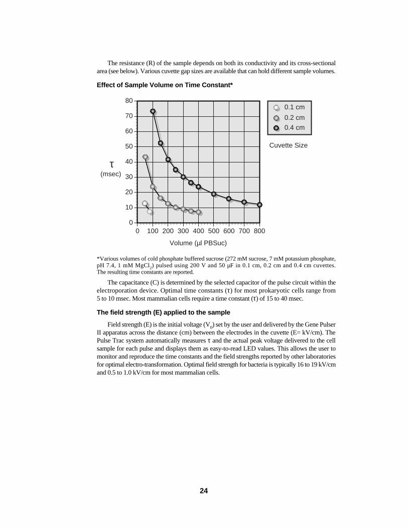
The resistance (R) of the sample depends on both its conductivity and its cross-sectionalarea (see below). Various cuvette gap sizes are available that can hold different sample volumes.
Effect of Sample Volume on Time Constant*
*Various volumes of cold phosphate buffered sucrose (272 mM sucrose, 7 mM potassium phosphate,pH 7.4, 1 mM MgCl2) pulsed using 200 V and 50 µF in 0.1 cm, 0.2 cm and 0.4 cm cuvettes. The resulting time constants are reported.
The capacitance (C) is determined by the selected capacitor of the pulse circuit within theelectroporation device. Optimal time constants (τ) for most prokaryotic cells range from 5 to 10 msec. Most mammalian cells require a time constant (τ) of 15 to 40 msec.
The field strength (E) applied to the sample
Field strength (E) is the initial voltage (V0) set by the user and delivered by the Gene PulserII apparatus across the distance (cm) between the electrodes in the cuvette (E= kV/cm). ThePulse Trac system automatically measures τ and the actual peak voltage delivered to the cellsample for each pulse and displays them as easy-to-read LED values. This allows the user tomonitor and reproduce the time constants and the field strengths reported by other laboratoriesfor optimal electro-transformation. Optimal field strength for bacteria is typically 16 to 19 kV/cmand 0.5 to 1.0 kV/cm for most mammalian cells.
0
10
20
30
40τ
50
60
70
80
0 100 200 300 400
Volume (µl PBSuc)
Cuvette Size
(msec)
500 600 700 800
0.1 cm
0.2 cm
0.4 cm
24