Embed Size (px)
Citation preview
SENTRON
Automatic Transfer Controller
ATC5300
Manual
Edition 02/2010A5E02469035-01
General Information 1
Functional Information 2
Applications 3
Parameter Setup 4
Wiring Diagrams 5
Appendix A
s
Legal information
Warning notice system
This manual contains notices you have to observe in order to ensure your personal safety, as well as to prevent damage to property. The notices referring to your personal safety are highlighted in the manual by a safety alert symbol, notices referring only to property damage have no safety alert symbol. These notices shown below are graded according to the degree of danger.
If more than one degree of danger is present, the warning notice representing the highest degree of danger will be used. A notice warning of injury to persons with a safety alert symbol may also include a warning relating to property damage.
Qualified Personnel
The product/system described in this documentation may be operated only by personnel qualified for the specific task in accordance with the relevant documentation for the specific task, in particular its warning notices and safety instructions. Qualified personnel are those who, based on their training and experience, are capable of identifying risks and avoiding potential hazards when working with these products/systems.
Proper use of Siemens products
Note the following:
Trademarks
All names identified by ® are registered trademarks of the Siemens AG. The remaining trademarks in this publication may be trademarks whose use by third parties for their own purposes could violate the rights of the owner.
Disclaimer of Liability
We have reviewed the contents of this publication to ensure consistency with the hardware and software described. Since variance cannot be precluded entirely, we cannot guarantee full consistency. However, the information in this publication is reviewed regularly and any necessary corrections are included in subsequent editions.
DANGER
indicates that death or severe personal injury will result if proper precautions are not taken.
WARNING
indicates that death or severe personal injury may result if proper precautions are not taken.
CAUTION
with a safety alert symbol, indicates that minor personal injury can result if proper precautions are not taken.
CAUTION
without a safety alert symbol, indicates that property damage can result if proper precautions are not taken.
NOTICE
indicates that an unintended result or situation can occur if the corresponding information is not taken into account.
WARNING
Siemens products may only be used for the applications described in the catalog and in the relevant technical documentation. If products and components from other manufacturers are used, these must be recommended or approved by Siemens. Proper transport, storage, installation, assembly, commissioning, operation and maintenance are required to ensure that the products operate safely and without any problems. The permissible ambient conditions must be adhered to. The information in the relevant documentation must be observed.
Siemens AGIndustry SectorPostfach 48 4890026 NÜRNBERGGERMANY
® 02.2010Copyright © Siemens AG 2010Technical data subject to change
ATC5300Manual, Edition 02/2010, A5E02469035-01 3
Table of ContentsTable of Contents
1 General Information . . . . . . . . . . . . . . . . . . . . . . . . . . . . . . . . . . . . . . . . . . . . . . . . . . . . . . . . . . . . . . . . . 5
1.1 Version . . . . . . . . . . . . . . . . . . . . . . . . . . . . . . . . . . . . . . . . . . . . . . . . . . . . . . . . . . . . . . . . . . . . 5
1.2 Description . . . . . . . . . . . . . . . . . . . . . . . . . . . . . . . . . . . . . . . . . . . . . . . . . . . . . . . . . . . . . . . . . . 5
1.3 Applications . . . . . . . . . . . . . . . . . . . . . . . . . . . . . . . . . . . . . . . . . . . . . . . . . . . . . . . . . . . . . . . . . 6
1.4 Installation . . . . . . . . . . . . . . . . . . . . . . . . . . . . . . . . . . . . . . . . . . . . . . . . . . . . . . . . . . . . . . . . . . 6
1.5 Notes about the Power Supply Circuits . . . . . . . . . . . . . . . . . . . . . . . . . . . . . . . . . . . . . . . . . . . . 6
2 Functional Information . . . . . . . . . . . . . . . . . . . . . . . . . . . . . . . . . . . . . . . . . . . . . . . . . . . . . . . . . . . . . . 7
2.1 Front Panel . . . . . . . . . . . . . . . . . . . . . . . . . . . . . . . . . . . . . . . . . . . . . . . . . . . . . . . . . . . . . . . . . 7
2.2 Measure Selection . . . . . . . . . . . . . . . . . . . . . . . . . . . . . . . . . . . . . . . . . . . . . . . . . . . . . . . . . . . . 8
2.3 Status LEDs . . . . . . . . . . . . . . . . . . . . . . . . . . . . . . . . . . . . . . . . . . . . . . . . . . . . . . . . . . . . . . . . . 8
2.4 Operating Mode Selection . . . . . . . . . . . . . . . . . . . . . . . . . . . . . . . . . . . . . . . . . . . . . . . . . . . . . . 92.4.1 OFF-RESET Mode . . . . . . . . . . . . . . . . . . . . . . . . . . . . . . . . . . . . . . . . . . . . . . . . . . . . . . . . . . . 92.4.2 MAN Mode . . . . . . . . . . . . . . . . . . . . . . . . . . . . . . . . . . . . . . . . . . . . . . . . . . . . . . . . . . . . . . . . . . 92.4.3 AUT Mode . . . . . . . . . . . . . . . . . . . . . . . . . . . . . . . . . . . . . . . . . . . . . . . . . . . . . . . . . . . . . . . . . 102.4.4 TEST Mode . . . . . . . . . . . . . . . . . . . . . . . . . . . . . . . . . . . . . . . . . . . . . . . . . . . . . . . . . . . . . . . . 102.4.5 Main Line Failure Simulation . . . . . . . . . . . . . . . . . . . . . . . . . . . . . . . . . . . . . . . . . . . . . . . . . . . 10
2.5 Voltage Controls . . . . . . . . . . . . . . . . . . . . . . . . . . . . . . . . . . . . . . . . . . . . . . . . . . . . . . . . . . . . 11
2.6 Real-Time Clock Setup . . . . . . . . . . . . . . . . . . . . . . . . . . . . . . . . . . . . . . . . . . . . . . . . . . . . . . . 12
2.7 Display of Statistic Data . . . . . . . . . . . . . . . . . . . . . . . . . . . . . . . . . . . . . . . . . . . . . . . . . . . . . . . 12
2.8 Alarms . . . . . . . . . . . . . . . . . . . . . . . . . . . . . . . . . . . . . . . . . . . . . . . . . . . . . . . . . . . . . . . . . . . . 13
2.9 Automatic Test . . . . . . . . . . . . . . . . . . . . . . . . . . . . . . . . . . . . . . . . . . . . . . . . . . . . . . . . . . . . . . 15
2.10 Diagnostic Messages . . . . . . . . . . . . . . . . . . . . . . . . . . . . . . . . . . . . . . . . . . . . . . . . . . . . . . . . 15
2.11 Keypad Lock . . . . . . . . . . . . . . . . . . . . . . . . . . . . . . . . . . . . . . . . . . . . . . . . . . . . . . . . . . . . . . . 16
2.12 Remote Control . . . . . . . . . . . . . . . . . . . . . . . . . . . . . . . . . . . . . . . . . . . . . . . . . . . . . . . . . . . . . 16
Table of Contents
Table of Contents
ATC53004 Manual, Edition 02/2010, A5E02469035-01
3 Applications . . . . . . . . . . . . . . . . . . . . . . . . . . . . . . . . . . . . . . . . . . . . . . . . . . . . . . . . . . . . . . . . . . . . . . 17
3.1 Utility-to-Generator Application . . . . . . . . . . . . . . . . . . . . . . . . . . . . . . . . . . . . . . . . . . . . . . . . . . 17
3.2 Utility-to-Utility Application . . . . . . . . . . . . . . . . . . . . . . . . . . . . . . . . . . . . . . . . . . . . . . . . . . . . . 17
3.3 Generator-to-Generator Application . . . . . . . . . . . . . . . . . . . . . . . . . . . . . . . . . . . . . . . . . . . . . . 17
3.4 EJP Function . . . . . . . . . . . . . . . . . . . . . . . . . . . . . . . . . . . . . . . . . . . . . . . . . . . . . . . . . . . . . . . 18
3.5 General Information . . . . . . . . . . . . . . . . . . . . . . . . . . . . . . . . . . . . . . . . . . . . . . . . . . . . . . . . . . 183.5.1 Control of Changeover Devices . . . . . . . . . . . . . . . . . . . . . . . . . . . . . . . . . . . . . . . . . . . . . . . . . 183.5.2 Control of Motorized Circuit Breakers . . . . . . . . . . . . . . . . . . . . . . . . . . . . . . . . . . . . . . . . . . . . . 183.5.3 Control of Motorized Changeover Switches . . . . . . . . . . . . . . . . . . . . . . . . . . . . . . . . . . . . . . . . 193.5.4 Contactors Control . . . . . . . . . . . . . . . . . . . . . . . . . . . . . . . . . . . . . . . . . . . . . . . . . . . . . . . . . . . 19
4 Parameter Setup . . . . . . . . . . . . . . . . . . . . . . . . . . . . . . . . . . . . . . . . . . . . . . . . . . . . . . . . . . . . . . . . . . . 21
4.1 Parameters Setup . . . . . . . . . . . . . . . . . . . . . . . . . . . . . . . . . . . . . . . . . . . . . . . . . . . . . . . . . . . . 21
4.2 Menu Table . . . . . . . . . . . . . . . . . . . . . . . . . . . . . . . . . . . . . . . . . . . . . . . . . . . . . . . . . . . . . . . . . 224.2.1 Menu P1 - System Ratings . . . . . . . . . . . . . . . . . . . . . . . . . . . . . . . . . . . . . . . . . . . . . . . . . . . . . 224.2.2 Menu P2 - General Data . . . . . . . . . . . . . . . . . . . . . . . . . . . . . . . . . . . . . . . . . . . . . . . . . . . . . . . 234.2.3 Menu P3 - Line 1 Voltage Control . . . . . . . . . . . . . . . . . . . . . . . . . . . . . . . . . . . . . . . . . . . . . . . . 254.2.4 Menu P4 - Line 2 Voltage Control . . . . . . . . . . . . . . . . . . . . . . . . . . . . . . . . . . . . . . . . . . . . . . . . 264.2.5 Menu P5 - Programmable Inputs . . . . . . . . . . . . . . . . . . . . . . . . . . . . . . . . . . . . . . . . . . . . . . . . 274.2.6 Menu P6 - Programmable Outputs . . . . . . . . . . . . . . . . . . . . . . . . . . . . . . . . . . . . . . . . . . . . . . . 294.2.7 Menu P7 - Communication Ports . . . . . . . . . . . . . . . . . . . . . . . . . . . . . . . . . . . . . . . . . . . . . . . . 314.2.8 Menu P8 - Automatic Test . . . . . . . . . . . . . . . . . . . . . . . . . . . . . . . . . . . . . . . . . . . . . . . . . . . . . 32
5 Wiring Diagrams . . . . . . . . . . . . . . . . . . . . . . . . . . . . . . . . . . . . . . . . . . . . . . . . . . . . . . . . . . . . . . . . . . . 33
5.1 General Connection . . . . . . . . . . . . . . . . . . . . . . . . . . . . . . . . . . . . . . . . . . . . . . . . . . . . . . . . . . 335.1.1 Motorized Circuit Breakers Control . . . . . . . . . . . . . . . . . . . . . . . . . . . . . . . . . . . . . . . . . . . . . . . 335.1.2 Motorized Changeover Switch Control . . . . . . . . . . . . . . . . . . . . . . . . . . . . . . . . . . . . . . . . . . . . 345.1.3 Contactors Control . . . . . . . . . . . . . . . . . . . . . . . . . . . . . . . . . . . . . . . . . . . . . . . . . . . . . . . . . . . 35
5.2 ATC5300 in Combination with SIEMENS Products . . . . . . . . . . . . . . . . . . . . . . . . . . . . . . . . . . 365.2.1 Circuit Breakers Accessories . . . . . . . . . . . . . . . . . . . . . . . . . . . . . . . . . . . . . . . . . . . . . . . . . . . 365.2.2 General Connection . . . . . . . . . . . . . . . . . . . . . . . . . . . . . . . . . . . . . . . . . . . . . . . . . . . . . . . . . . 375.2.3 SENTRON 3VL . . . . . . . . . . . . . . . . . . . . . . . . . . . . . . . . . . . . . . . . . . . . . . . . . . . . . . . . . . . . . . 385.2.4 SENTRON 3VT . . . . . . . . . . . . . . . . . . . . . . . . . . . . . . . . . . . . . . . . . . . . . . . . . . . . . . . . . . . . . . 405.2.5 SENTRON 3WL . . . . . . . . . . . . . . . . . . . . . . . . . . . . . . . . . . . . . . . . . . . . . . . . . . . . . . . . . . . . . 435.2.6 SENTRON 3WT8 . . . . . . . . . . . . . . . . . . . . . . . . . . . . . . . . . . . . . . . . . . . . . . . . . . . . . . . . . . . . 44
5.3 Mechanical Dimensions and Panel Cut-Out . . . . . . . . . . . . . . . . . . . . . . . . . . . . . . . . . . . . . . . . 45
5.4 RS 485 Interface Wiring . . . . . . . . . . . . . . . . . . . . . . . . . . . . . . . . . . . . . . . . . . . . . . . . . . . . . . . 45
5.5 Technical Characteristics . . . . . . . . . . . . . . . . . . . . . . . . . . . . . . . . . . . . . . . . . . . . . . . . . . . . . . 465.5.1 SENTRON 3VL . . . . . . . . . . . . . . . . . . . . . . . . . . . . . . . . . . . . . . . . . . . . . . . . . . . . . . . . . . . . . . 475.5.2 SENTRON 3VT . . . . . . . . . . . . . . . . . . . . . . . . . . . . . . . . . . . . . . . . . . . . . . . . . . . . . . . . . . . . . . 47
6 Appendix . . . . . . . . . . . . . . . . . . . . . . . . . . . . . . . . . . . . . . . . . . . . . . . . . . . . . . . . . . . . . . . . . . . . . . . . . 49
ATC5300Manual, Edition 02/2010, A5E02469035-01 5
General Information 1General Information
1.1 Version
• SENTRON ATC5300 - housing 144 x 144 mm with calendar clock and RS 485 interface.
1.2 Description
• Microprocessor-based automatic transfer switch.
• Two measure inputs for three-phase + neutral voltage.
• DC 12-24-48 V power supply.
• AC 220-240 V power supply.
• Two 3-digit 7-segment LED displays.
• 22 status and measure LED indicators.
• 8-key membrane keypad.
• RS 232 serial interface for set-up, remote control and supervision.
• RS 485 opto-isolated interface (ATC5300).
• Calendar watch with event gathering (ATC5300).
• Non-volatile memory for events and statistical data.
• 8 programmable digital inputs.
• 7 programmable relay outputs (5 NO + 2 NC / NO).
Warning
This equipment must be installed by trained personnel, complying to current standards, to avoid damages or safety hazards. Products illustrated herein are subject to alterations and changes without prior notice.
• Technical data and descriptions in the publication are accurate, to the best of our knowledge, but no liabilities for errors, omissions or contingencies arising therefrom are accepted.
• A magneto-thermal circuit breaker must be included in the electrical installation of the building. It must be installed close by the equipment and within easy reach of the operator. It must be marked as the disconnecting device of the equipment: IEC / EN 61010-1 § 6.12.2.1
• Fit the instrument in an enclosure or cabinet with minimum IP40 degree protection.
General Information
1.3 Applications
ATC53006 Manual, Edition 02/2010, A5E02469035-01
1.3 Applications
• Utility-to-utility, utility-to-generator or generator-to-generator changeover.
• Control of motorized circuit breakers, motorized switches or contactors.
• Generator management with automatic test and rotation-emergency.
• Three-phase, two-phase or single-phase voltage controls.
• L-L voltage and / or L-N voltage control.
• Controls of minimum voltage, maximum voltage, phase loss, asymmetry, minimum frequency, maximum frequency, with independent enable and delay.
• Voltage thresholds with programmable hysteresis.
1.4 Installation
• Install the unit following the wiring diagrams on the last pages of this manual.
• Use the appropriate wiring diagram for the application.
• Program parameters as a function of the wiring diagram adopted and pay particular attention to the programming of inputs / outputs.
1.5 Notes about the Power Supply Circuits
• SENTRON ATC5300 has a double power supply circuit, that means that it can operate with both AC and DC supply or with only one of the two indifferently.
• In presence of both power supplies, the energy is taken from the AC source. In this case only a little power is drawn from the DC source, needed to allow operation of the supply circuit itself.
ATC5300Manual, Edition 02/2010, A5E02469035-01 7
Functional Information 2Functional Information
2.1 Front Panel
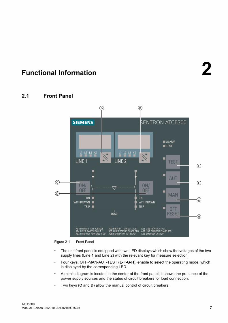
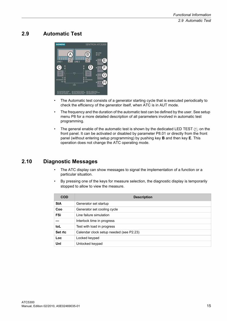
Figure 2-1 Front Panel
• The unit front panel is equipped with two LED displays which show the voltages of the two supply lines (Line 1 and Line 2) with the relevant key for measure selection.
• Four keys, OFF-MAN-AUT-TEST (E-F-G-H), enable to select the operating mode, which is displayed by the corresponding LED.
• A mimic diagram is located in the center of the front panel; it shows the presence of the power supply sources and the status of circuit breakers for load connection.
• Two keys (C and D) allow the manual control of circuit breakers.
Functional Information
2.2 Measure Selection
ATC53008 Manual, Edition 02/2010, A5E02469035-01
2.2 Measure Selection
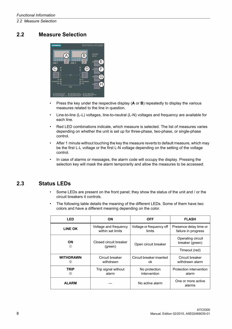
• Press the key under the respective display (A or B) repeatedly to display the various measures related to the line in question.
• Line-to-line (L-L) voltages, line-to-neutral (L-N) voltages and frequency are available for each line.
• Red LED combinations indicate, which measure is selected. The list of measures varies depending on whether the unit is set up for three-phase, two-phase, or single-phase control.
• After 1 minute without touching the key the measure reverts to default measure, which may be the first L-L voltage or the first L-N voltage depending on the setting of the voltage control.
• In case of alarms or messages, the alarm code will occupy the display. Pressing the selection key will mask the alarm temporarily and allow the measures to be accessed.
2.3 Status LEDs
• Some LEDs are present on the front panel; they show the status of the unit and / or the circuit breakers it controls.
• The following table details the meaning of the different LEDs. Some of them have two colors and have a different meaning depending on the color.
LED ON OFF FLASH
LINE OKVoltage and frequency
within set limitsVoltage or frequency off
limitsPresence delay time or
failure in progress
ON¿
Closed circuit breaker (green)
Open circuit breaker
Operating circuit breaker (green)
Timeout (red)
WITHDRAWNÀ
Circuit breaker withdrawn
Circuit breaker inserted ok
Circuit breaker withdrawn alarm
TRIPÀ
Trip signal without alarm
No protection intervention
Protection intervention alarm
ALARM — No active alarmOne or more active
alarms
Functional Information
2.4 Operating Mode Selection
ATC5300Manual, Edition 02/2010, A5E02469035-01 9
2.4 Operating Mode Selection
• The four keys OFF-RESET / MAN / AUT / TEST allow to select the required operating mode, which will be shown when the corresponding red LED lights up.
• If the LED showing the selected operating mode flashes, it indicates that the unit is communicating through the serial interface and that it might perform commands given from remote, including even the change of the mode itself.
2.4.1 OFF-RESET Mode
• In this mode the unit is disabled, and does not perform any actions.
• All visual displays, concerning both measures and status LEDs, remain active.
• If the control of changeover devices is the pulse-type, in OFF-RESET both controls remain disabled. On the contrary, if it is in continuous control mode, the behaviour depends upon P2.25 programming.
• To access programming menus it is always necessary to shift to OFF-RESET mode beforehand.
• By pressing the OFF-RESET key retentive alarms can be cleared, provided that the conditions generating the alarm have been removed.
2.4.2 MAN Mode
• In MAN mode it is possible to control circuit breakers manually by pressing the relevant key (C and D keys) for a minimum time of 300 ms.
• At each key pressure the circuit breaker status is switched over. The command is accepted only when 1 sec has elapsed from the end of the previous switching.
• If a manual command is given to close a circuit breaker while the other is still closed, the unit will first open the other circuit breaker and then close the one commanded, while interposing the programmed interlock time.
• When operating with a generator set, the generator startup and shutdown can be manually commanded on the secondary line by pressing and holding down the MAN key for 5 seconds.
TESTAutomatic test enabled
(green)Automatic test disabled
Automatic test in progress (green)
Calender watch not set (red)
¿ If auxiliary signals (feedback) have been suitably connected and programmed, the LEDs represent the circuit breakers status; otherwise they represent the status of control outputs.
À If the respective signals were suitably connected and programmed, the LEDs represent the circuit breakers status, if not LEDs will remain off.
LED ON OFF FLASH
ATC530010 Manual, Edition 02/2010, A5E02469035-01
2.4.3 AUT Mode
• In automatic mode the unit itself performs both circuit breaker opening and closing operations, the startup and shutdown of the generator set, if any.
• When the main line exceeds the limits, after the set delay times (line LED off), the unit disconnects the load from the main line and connects it to the secondary line, controlling both the startup of the generator set, if any, and the handling and interlock times between circuit breakers.
• The unit may be programmed to disconnect the load from the main line before or after the secondary line has been made available.
• When the main line returns within the limits, the unit switches over the load again and controls the generator set cooling cycle, if any.
• Automatic operating cycles vary both as a function of the type of application (utility-to-utility, utility-to-generator or generator-to-generator) and as a function of the type of switching devices used (motorized circuit breakers, switches or contactors).
2.4.4 TEST Mode
• The TEST mode allows to control the proper operation of the generator set also under standard presence conditions of the main line.
• When shifting to TEST the generator set on the secondary line is immediately started.
• Both voltage controls are activated and, if an anomaly occurs on the main line during the test, the load is switched over automatically.
• Under standard conditions of main line presence, load remains on the line and the generator set works with no load (off-load test).
• If you want to shift the load to the generator (on-load test), press key E (TEST) and key D (line 2 ON-OFF) together for 5 seconds.
• In TEST mode, once the load has been shifted to the generator, either due to a main line failure or to perform an on-load test, it does not revert automatically to the main line, unless you switch to AUT mode.
• Delay and interlock times are the same as in the automatic mode.
2.4.5 Main Line Failure Simulation
• Starting from the automatic mode, it is possible to simulate a 1 min. voltage failure on the main line.
• The unit will respond in the same manner and timeframe set for standard automatic operation. The proper operation of transfer cycles may thus be controlled.
• Starting from AUT mode, press the AUT key and the line 2 ON-OFF key together for 10 consecutive seconds.
• The letters F.SI (Failure Simulation) will be shown on the display during the execution of the whole cycle.
• To stop the test before completion, repeat the starting procedure or switch to OFF-RESET mode.
Functional Information
2.5 Voltage Controls
ATC5300Manual, Edition 02/2010, A5E02469035-01 11
2.5 Voltage Controls
• All the conditions which can help establish whether a power source is or is not suitable are defined by the user through menu P1 (ratings) and menus P3 and P4 (line 1 and line 2 voltage limits, respectively).
• The system ratings can be set through menu P1, including rated voltage and frequency, which will be used as reference to set percent thresholds.
• A voltage ratio (TV) can be set whenever a voltage lower than the actual system voltage is applied to the unit voltage inputs. Also in this case, both the visualization and the setting of thresholds will be implemented in actual magnitudes referred to the system.
• The controller can be programmed to perform voltage controls on three-phase with or without neutral, two-phase or single-phase utilities (P1.03).
• In the case of three-phase or two-phase utility, you can choose whether to monitor L-L voltage or L-N voltage, or both (P1.04). In every case, the rated voltage set with P1.01 has to be equal to the phase-to-phase voltage.
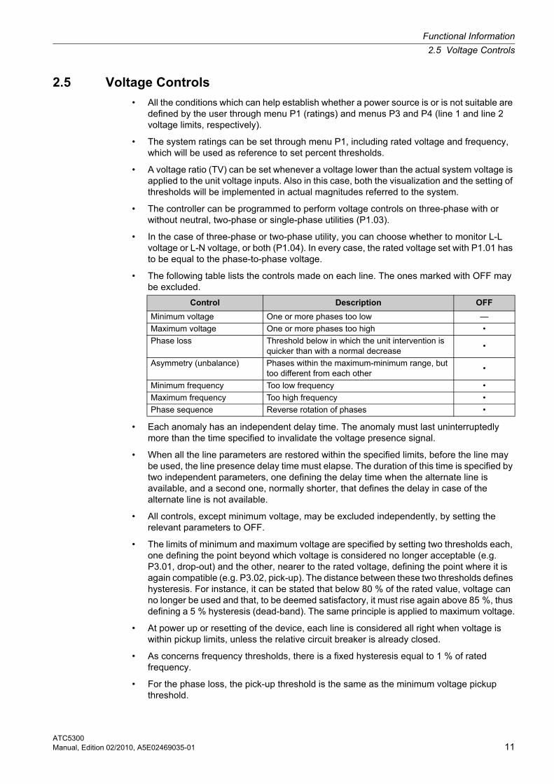
• The following table lists the controls made on each line. The ones marked with OFF may be excluded.
• Each anomaly has an independent delay time. The anomaly must last uninterruptedly more than the time specified to invalidate the voltage presence signal.
• When all the line parameters are restored within the specified limits, before the line may be used, the line presence delay time must elapse. The duration of this time is specified by two independent parameters, one defining the delay time when the alternate line is available, and a second one, normally shorter, that defines the delay in case of the alternate line is not available.
• All controls, except minimum voltage, may be excluded independently, by setting the relevant parameters to OFF.
• The limits of minimum and maximum voltage are specified by setting two thresholds each, one defining the point beyond which voltage is considered no longer acceptable (e.g. P3.01, drop-out) and the other, nearer to the rated voltage, defining the point where it is again compatible (e.g. P3.02, pick-up). The distance between these two thresholds defines hysteresis. For instance, it can be stated that below 80 % of the rated value, voltage can no longer be used and that, to be deemed satisfactory, it must rise again above 85 %, thus defining a 5 % hysteresis (dead-band). The same principle is applied to maximum voltage.
• At power up or resetting of the device, each line is considered all right when voltage is within pickup limits, unless the relative circuit breaker is already closed.
• As concerns frequency thresholds, there is a fixed hysteresis equal to 1 % of rated frequency.
• For the phase loss, the pick-up threshold is the same as the minimum voltage pickup threshold.
Control Description OFF
Minimum voltage One or more phases too low —
Maximum voltage One or more phases too high •
Phase loss Threshold below in which the unit intervention is quicker than with a normal decrease
•
Asymmetry (unbalance) Phases within the maximum-minimum range, but too different from each other
•
Minimum frequency Too low frequency •
Maximum frequency Too high frequency •
Phase sequence Reverse rotation of phases •
Functional Information
2.6 Real-Time Clock Setup
ATC530012 Manual, Edition 02/2010, A5E02469035-01
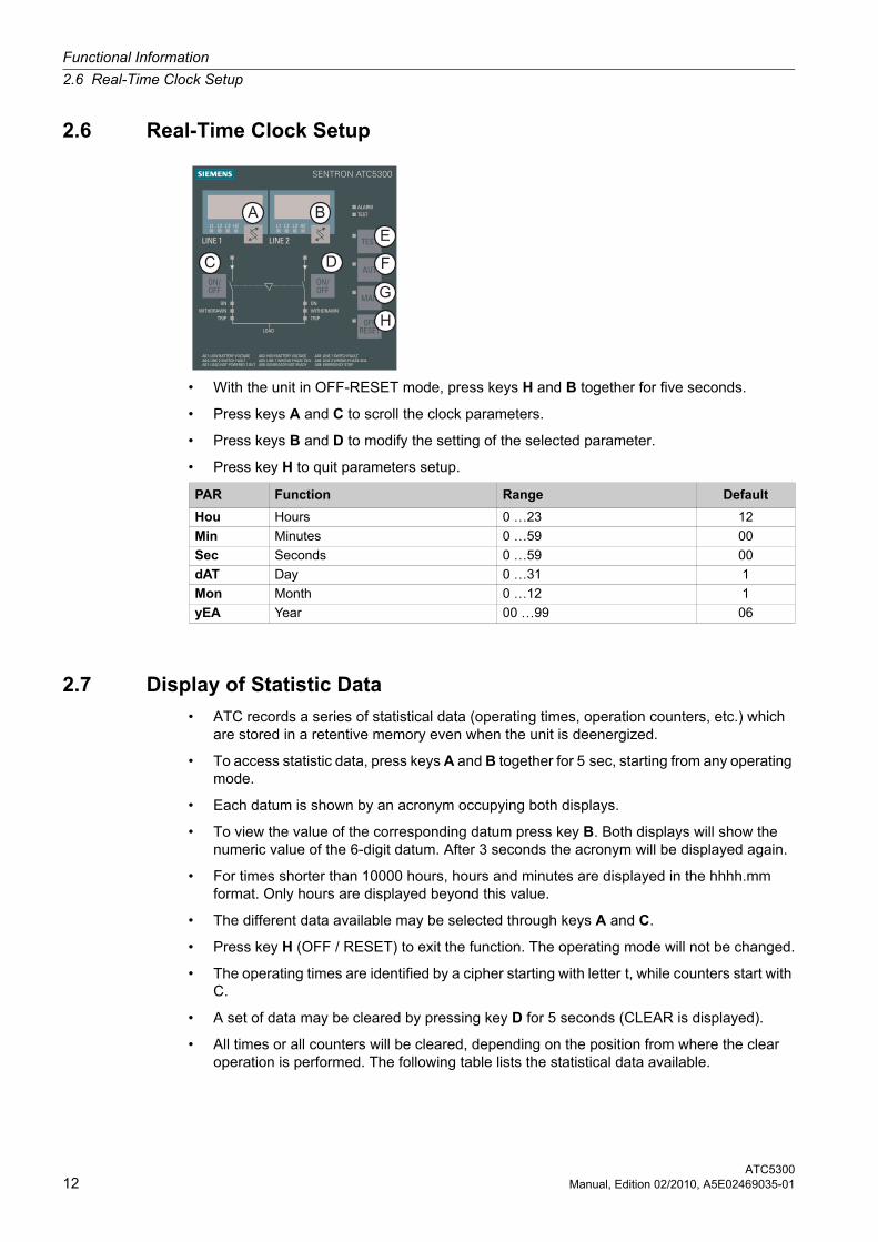
2.6 Real-Time Clock Setup
• With the unit in OFF-RESET mode, press keys H and B together for five seconds.
• Press keys A and C to scroll the clock parameters.
• Press keys B and D to modify the setting of the selected parameter.
• Press key H to quit parameters setup.
2.7 Display of Statistic Data
• ATC records a series of statistical data (operating times, operation counters, etc.) which are stored in a retentive memory even when the unit is deenergized.
• To access statistic data, press keys A and B together for 5 sec, starting from any operating mode.
• Each datum is shown by an acronym occupying both displays.
• To view the value of the corresponding datum press key B. Both displays will show the numeric value of the 6-digit datum. After 3 seconds the acronym will be displayed again.
• For times shorter than 10000 hours, hours and minutes are displayed in the hhhh.mm format. Only hours are displayed beyond this value.
• The different data available may be selected through keys A and C.
• Press key H (OFF / RESET) to exit the function. The operating mode will not be changed.
• The operating times are identified by a cipher starting with letter t, while counters start with C.
• A set of data may be cleared by pressing key D for 5 seconds (CLEAR is displayed).
• All times or all counters will be cleared, depending on the position from where the clear operation is performed. The following table lists the statistical data available.
PAR Function Range Default
Hou Hours 0 …23 12
Min Minutes 0 …59 00
Sec Seconds 0 …59 00
dAT Day 0 …31 1
Mon Month 0 …12 1
yEA Year 00 …99 06
Functional Information
2.8 Alarms
ATC5300Manual, Edition 02/2010, A5E02469035-01 13
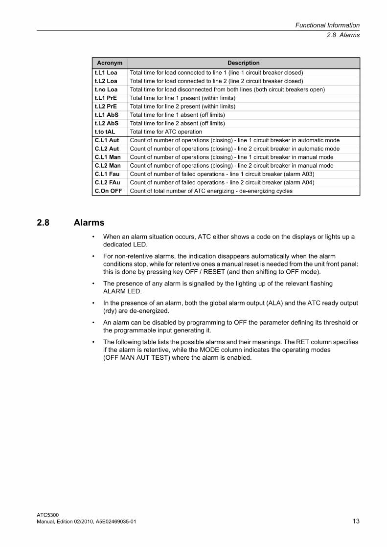
2.8 Alarms
• When an alarm situation occurs, ATC either shows a code on the displays or lights up a dedicated LED.
• For non-retentive alarms, the indication disappears automatically when the alarm conditions stop, while for retentive ones a manual reset is needed from the unit front panel: this is done by pressing key OFF / RESET (and then shifting to OFF mode).
• The presence of any alarm is signalled by the lighting up of the relevant flashing ALARM LED.
• In the presence of an alarm, both the global alarm output (ALA) and the ATC ready output (rdy) are de-energized.
• An alarm can be disabled by programming to OFF the parameter defining its threshold or the programmable input generating it.
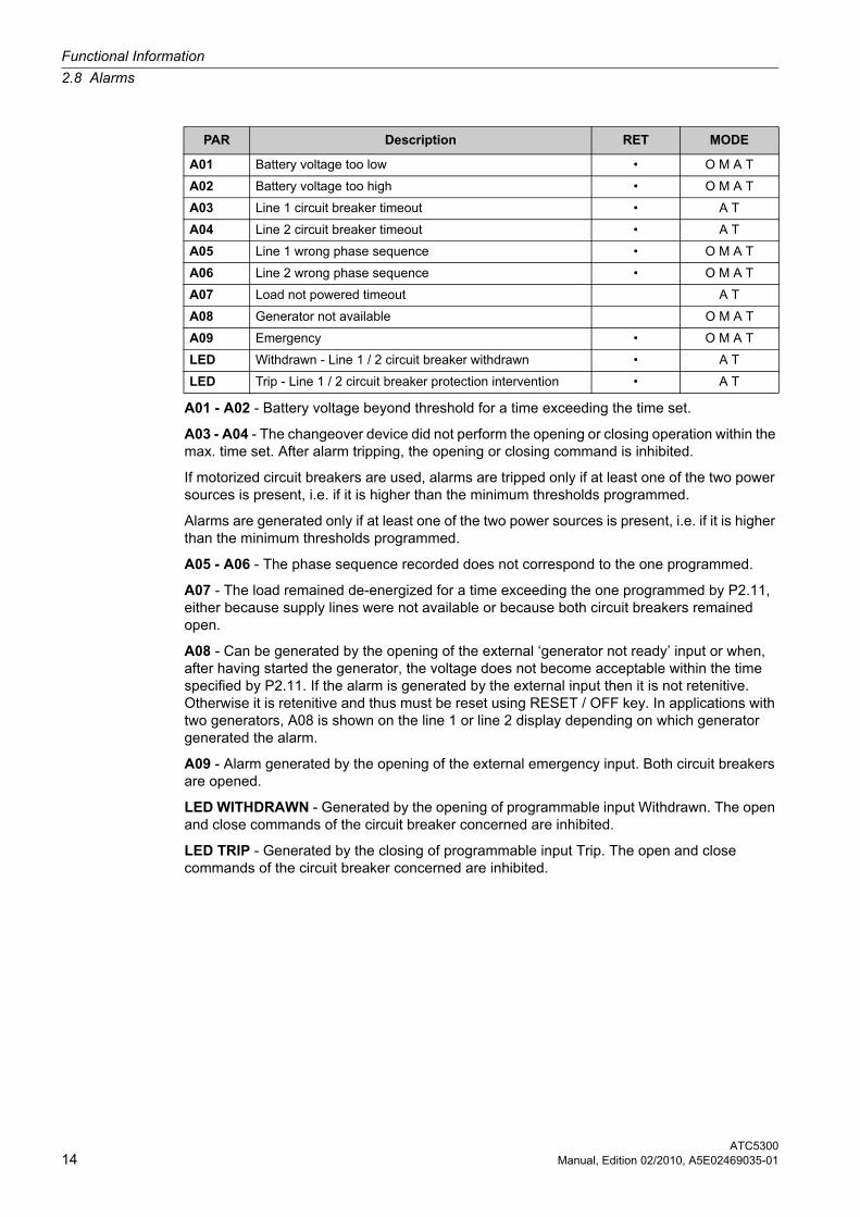
• The following table lists the possible alarms and their meanings. The RET column specifies if the alarm is retentive, while the MODE column indicates the operating modes (OFF MAN AUT TEST) where the alarm is enabled.
Acronym Description
t.L1 Loa Total time for load connected to line 1 (line 1 circuit breaker closed)
t.L2 Loa Total time for load connected to line 2 (line 2 circuit breaker closed)
t.no Loa Total time for load disconnected from both lines (both circuit breakers open)
t.L1 PrE Total time for line 1 present (within limits)
t.L2 PrE Total time for line 2 present (within limits)
t.L1 AbS Total time for line 1 absent (off limits)
t.L2 AbS Total time for line 2 absent (off limits)
t.to tAL Total time for ATC operation
C.L1 Aut Count of number of operations (closing) - line 1 circuit breaker in automatic mode
C.L2 Aut Count of number of operations (closing) - line 2 circuit breaker in automatic mode
C.L1 Man Count of number of operations (closing) - line 1 circuit breaker in manual mode
C.L2 Man Count of number of operations (closing) - line 2 circuit breaker in manual mode
C.L1 Fau Count of number of failed operations - line 1 circuit breaker (alarm A03)
C.L2 FAu Count of number of failed operations - line 2 circuit breaker (alarm A04)
C.On OFF Count of total number of ATC energizing - de-energizing cycles
Functional Information
2.8 Alarms
ATC530014 Manual, Edition 02/2010, A5E02469035-01
A01 - A02 - Battery voltage beyond threshold for a time exceeding the time set.
A03 - A04 - The changeover device did not perform the opening or closing operation within the max. time set. After alarm tripping, the opening or closing command is inhibited.
If motorized circuit breakers are used, alarms are tripped only if at least one of the two power sources is present, i.e. if it is higher than the minimum thresholds programmed.
Alarms are generated only if at least one of the two power sources is present, i.e. if it is higher than the minimum thresholds programmed.
A05 - A06 - The phase sequence recorded does not correspond to the one programmed.
A07 - The load remained de-energized for a time exceeding the one programmed by P2.11, either because supply lines were not available or because both circuit breakers remained open.
A08 - Can be generated by the opening of the external ‘generator not ready’ input or when, after having started the generator, the voltage does not become acceptable within the time specified by P2.11. If the alarm is generated by the external input then it is not retenitive. Otherwise it is retenitive and thus must be reset using RESET / OFF key. In applications with two generators, A08 is shown on the line 1 or line 2 display depending on which generator generated the alarm.
A09 - Alarm generated by the opening of the external emergency input. Both circuit breakers are opened.
LED WITHDRAWN - Generated by the opening of programmable input Withdrawn. The open and close commands of the circuit breaker concerned are inhibited.
LED TRIP - Generated by the closing of programmable input Trip. The open and close commands of the circuit breaker concerned are inhibited.
PAR Description RET MODE
A01 Battery voltage too low • O M A T
A02 Battery voltage too high • O M A T
A03 Line 1 circuit breaker timeout • A T
A04 Line 2 circuit breaker timeout • A T
A05 Line 1 wrong phase sequence • O M A T
A06 Line 2 wrong phase sequence • O M A T
A07 Load not powered timeout A T
A08 Generator not available O M A T
A09 Emergency • O M A T
LED Withdrawn - Line 1 / 2 circuit breaker withdrawn • A T
LED Trip - Line 1 / 2 circuit breaker protection intervention • A T
Functional Information
2.9 Automatic Test
ATC5300Manual, Edition 02/2010, A5E02469035-01 15
2.9 Automatic Test
• The Automatic test consists of a generator starting cycle that is executed periodically to check the efficiency of the generator itself, when ATC is in AUT mode.
• The frequency and the duration of the automatic test can be defined by the user. See setup menu P8 for a more detailed description of all parameters involved in automatic test programming.
• The general enable of the automatic test is shown by the dedicated LED TEST on the front panel. It can be activated or disabled by parameter P8.01 or directly from the front panel (without entering setup programming) by pushing key B and then key E. This operation does not change the ATC operating mode.
2.10 Diagnostic Messages
• The ATC display can show messages to signal the implementation of a function or a particular situation.
• By pressing one of the keys for measure selection, the diagnostic display is temporarily stopped to allow to view the measure.
COD Description
StA Generator set startup
Coo Generator set cooling cycle
FSi Line failure simulation
— Interlock time in progress
toL Test with load in progress
Set rtc Calendar clock setup needed (see P2.23)
Loc Locked keypad
Unl Unlocked keypad
Functional Information
2.11 Keypad Lock
ATC530016 Manual, Edition 02/2010, A5E02469035-01
2.11 Keypad Lock
• The ATC keypad can be locked either by means of a programmable input or with a particular procedure from front keys.
• Once the keypad is locked, it will only be possible to view measures, but not to change operating mode or to operate manually on circuit breakers. Only the keys for measure selection will remain enabled.
• Any attempt to use the locked keys will cause the word Loc to be displayed.
• To lock or unlock the keypad, press key A and, while holding it down, press key B three times without releasing it at the end.
• Then release key A and press it 5 times, then release both keys.
• When the keypad is locked, the display shows the word Loc. When the keypad is unlocked, the display shows the word UnL.
2.12 Remote Control
• It is possible to connect ATC to a PC through its serial interface and to monitor the operation of the device using SENTRON SOFTWARE ATC or using a generic SCADA software that supports Modbus protocol.
• ATC5300 can be connected directly in peer-to-peer configuration using the RS 232 serial interface port and the attached cable to the software.
• ATC5300 can also be connected through RS 485 interface in a network configuration, using the wiring diagrams reported on the following pages.
ATC5300Manual, Edition 02/2010, A5E02469035-01 17
Applications 3Applications
3.1 Utility-to-Generator Application
• In the utility-to-generator application (U-G, default setting) the load is usually connected to the utility (Line 1). Following voltage or frequency anomaly, after the delay set in P2.15, a start signal is sent to generator (Line 2).
• When generator voltage is within programmed limits, the load is connected to the generator end until the utility line reverts to standard values.
• At this time the load is transferred back and the generator is kept in operation without load for a time set by P2.16 to allow it to cool.
• The ATC switch sends a start / stop command to the generator through a relay output and can receive digital signals from the generator indicating its status (generator ready, ok to load taking, etc) through programmable inputs.
• An automatic test can be programmed, i.e. the generator can be started at set times to control its operation even if the utility is generally within limits, by setting execution interval, starting time, days of the week when the test shall be carried out, its duration, etc.. Refer to the relevant menu to set the automatic test.
3.2 Utility-to-Utility Application
• In the utility-to-utility (U-U) application, the load is usually connected to the main utility and the transfer to the secondary utility occurs if / when the main line anomaly or transfer signal is given from the outside.
3.3 Generator-to-Generator Application
• In this case two generators are controlled, each with a start-stop relay and feedback signals, if any.
• In this application a rotation between generators can be programmed, i.e. the load can be shifted from one to the other at regular intervals, with the purpose of sharing out the generator work equally.
• It is also possible to set the time of day when rotation shall occur, so that load supply cut-off occurs at a specified time.
• In case of a problem to either generator, the load is shifted to the one in stand-by in all cases.
Applications
3.4 EJP Function
ATC530018 Manual, Edition 02/2010, A5E02469035-01
3.4 EJP Function
• For applications requiring the EJP function, it is possible to use two programmable inputs set to functions S.GE (start generator) and E.tr (External transfer).
• Parameter P2.26 can also be used to define a generator start delay.
3.5 General Information
3.5.1 Control of Changeover Devices
• For the line changeover, ATC can control different types of devices such as motorized circuit breakers, motorized changeovers or contactors.
• Depending on the type of changeover devices used with the ATC, appropriate wiring diagrams shall be used with related programming of programmable inputs / outputs.
• Programmable outputs are set by default for the application with motorized circuit breakers. See the attached wiring diagrams at the end of this manual.
• The device status feedback inputs shall be normally wired, so as to ensure reliable system operation.
• Nonetheless, it is however possible to avoid their wiring and set programmable inputs for other functions. In this case the unit behaves as if the device carried out at once the command sent.
• If the device status inputs are not used, then ATC, after power-on, sends an open command to bring the switching devices in a defined position.
• If instead the device status inputs are used, then ATC, after power-on, does not send commands to the switching device until the relative line status is not stable, that is when the presence / absence delay have elapsed.
• Internal control relays are neither interlocked electrically nor mechanically.
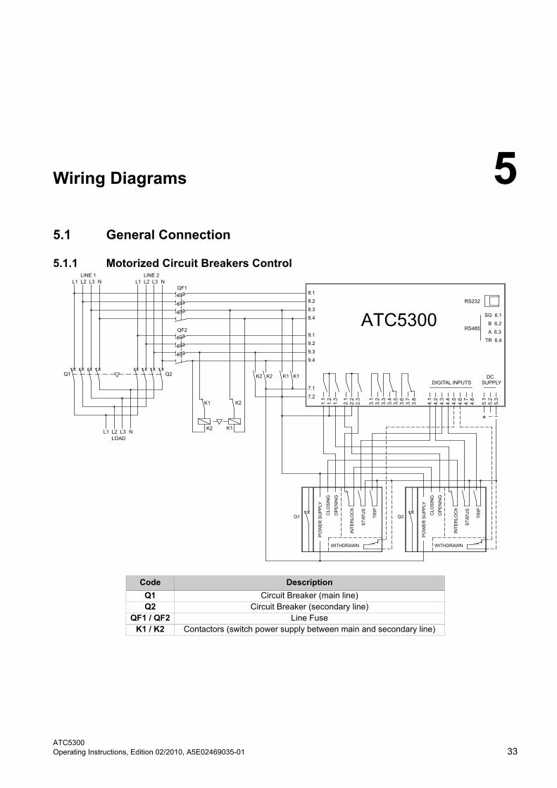
3.5.2 Control of Motorized Circuit Breakers
• For the control of motorized circuit breakers, 4 outputs are needed (open and close commands for line 1 and line 2) and two inputs for circuit breakers status feedback, plus any additional optional inputs for alarm signalling (WITHDRAWN and TRIP).
• Open and close commands can be kept in continuous or pulse mode, i.e. kept until the circuit breaker has reached the required position + safety time.
• The two command modes can be selected through the appropriate parameter P2.07, set on "COn" or "PUL" in the general data menu.
• TRIP inputs are ignored for a 15-second window every time an open command is sent to circuit breakers. This prevents a false alarm from being activated if the circuit breakers temporarily send a TRIP signal during the opening through their release coil.
• A 0.5-second interval is interposed between the opening and closing commands of the same circuit breaker.
• If feedback inputs are used, should the circuit breaker not close, a second attempt is conducted before generating the alarm.
Applications
3.5 General Information
ATC5300Manual, Edition 02/2010, A5E02469035-01 19
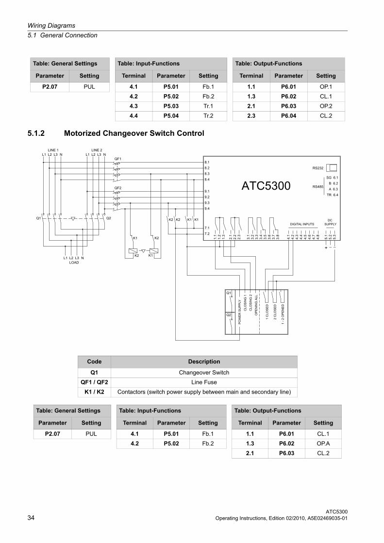
3.5.3 Control of Motorized Changeover Switches
• The application with motorized switches is very similar to the previous one, but provides for the use of three outputs only (line 1, line 2 and all open positions) and two inputs for circuit breaker status.
• CL.1, CL.2 and OP.A output functions and Fb.1 and Fb.2 input functions are required.
• It is possible to select the command mode, either pulse or continuous.
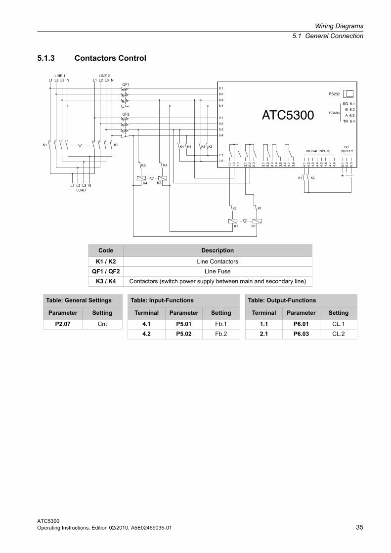
3.5.4 Contactors Control
• If a pair of contactors is used, two outputs (CL.1 and CL.2) and two status inputs are required.
• In this case, the command must be programmed in contactors control mode (P2.07 = Cnt).

Applications
3.5 General Information
ATC530020 Manual, Edition 02/2010, A5E02469035-01
ATC5300Manual, Edition 02/2010, A5E02469035-01 21
Parameter Setup 4Parameter Setup
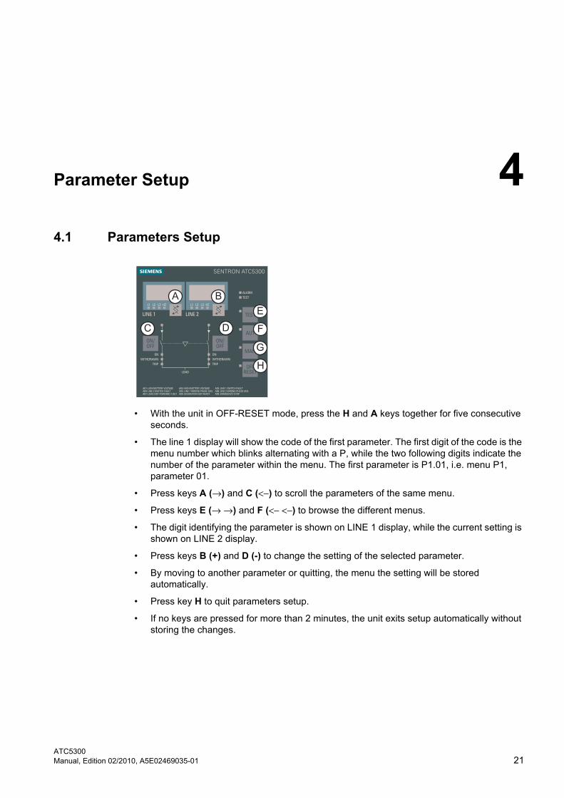
4.1 Parameters Setup
• With the unit in OFF-RESET mode, press the H and A keys together for five consecutive seconds.
• The line 1 display will show the code of the first parameter. The first digit of the code is the menu number which blinks alternating with a P, while the two following digits indicate the number of the parameter within the menu. The first parameter is P1.01, i.e. menu P1, parameter 01.
• Press keys A (→) and C (<−) to scroll the parameters of the same menu.
• Press keys E (→ →) and F (<− <−) to browse the different menus.
• The digit identifying the parameter is shown on LINE 1 display, while the current setting is shown on LINE 2 display.
• Press keys B (+) and D (-) to change the setting of the selected parameter.
• By moving to another parameter or quitting, the menu the setting will be stored automatically.
• Press key H to quit parameters setup.
• If no keys are pressed for more than 2 minutes, the unit exits setup automatically without storing the changes.
Parameter Setup
4.2 Menu Table
ATC530022 Manual, Edition 02/2010, A5E02469035-01
4.2 Menu Table
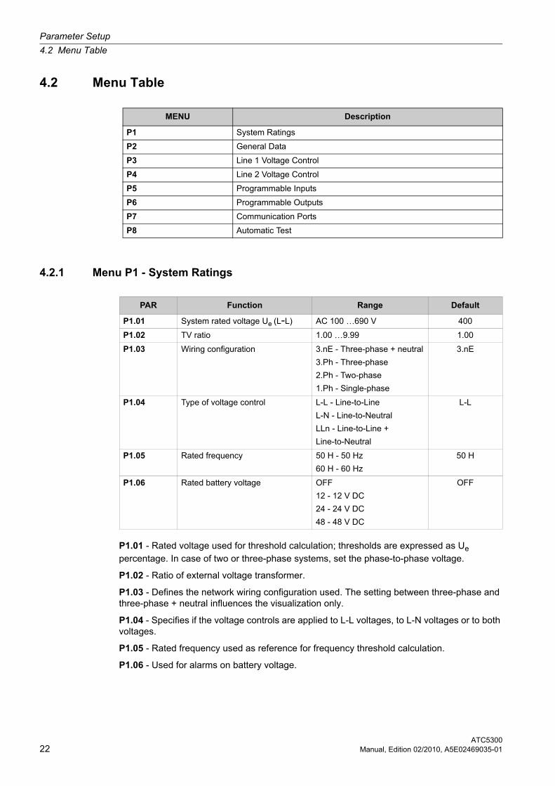
4.2.1 Menu P1 - System Ratings
P1.01 - Rated voltage used for threshold calculation; thresholds are expressed as Ue percentage. In case of two or three-phase systems, set the phase-to-phase voltage.
P1.02 - Ratio of external voltage transformer.
P1.03 - Defines the network wiring configuration used. The setting between three-phase and three-phase + neutral influences the visualization only.
P1.04 - Specifies if the voltage controls are applied to L-L voltages, to L-N voltages or to both voltages.
P1.05 - Rated frequency used as reference for frequency threshold calculation.
P1.06 - Used for alarms on battery voltage.
MENU Description
P1 System Ratings
P2 General Data
P3 Line 1 Voltage Control
P4 Line 2 Voltage Control
P5 Programmable Inputs
P6 Programmable Outputs
P7 Communication Ports
P8 Automatic Test
PAR Function Range Default
P1.01 System rated voltage Ue (L-L) AC 100 …690 V 400
P1.02 TV ratio 1.00 …9.99 1.00
P1.03 Wiring configuration 3.nE - Three-phase + neutral
3.Ph - Three-phase
2.Ph - Two-phase
1.Ph - Single-phase
3.nE
P1.04 Type of voltage control L-L - Line-to-Line
L-N - Line-to-Neutral
LLn - Line-to-Line +
Line-to-Neutral
L-L
P1.05 Rated frequency 50 H - 50 Hz
60 H - 60 Hz
50 H
P1.06 Rated battery voltage OFF
12 - 12 V DC
24 - 24 V DC
48 - 48 V DC
OFF
Parameter Setup
4.2 Menu Table
ATC5300Manual, Edition 02/2010, A5E02469035-01 23
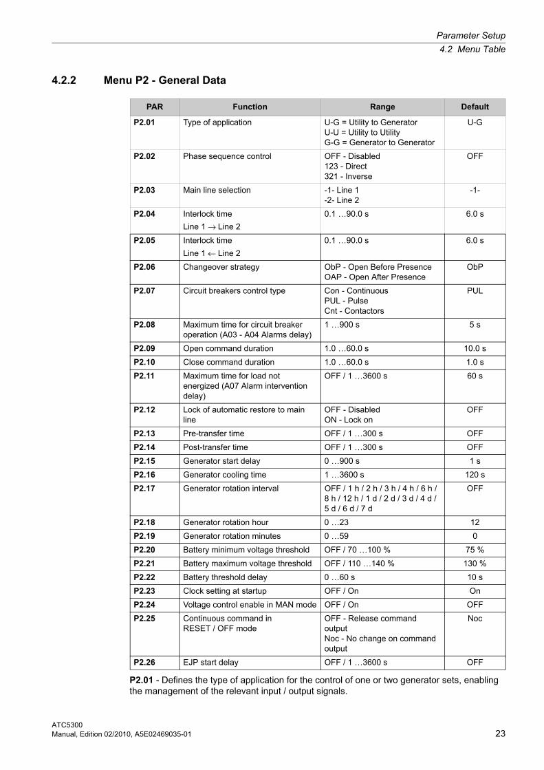
4.2.2 Menu P2 - General Data
P2.01 - Defines the type of application for the control of one or two generator sets, enabling the management of the relevant input / output signals.
PAR Function Range Default
P2.01 Type of application U-G = Utility to Generator U-U = Utility to Utility G-G = Generator to Generator
U-G
P2.02 Phase sequence control OFF - Disabled 123 - Direct 321 - Inverse
OFF
P2.03 Main line selection -1- Line 1-2- Line 2
-1-
P2.04 Interlock time
Line 1 → Line 2
0.1 …90.0 s 6.0 s
P2.05 Interlock time
Line 1 ← Line 2
0.1 …90.0 s 6.0 s
P2.06 Changeover strategy ObP - Open Before Presence OAP - Open After Presence
ObP
P2.07 Circuit breakers control type Con - Continuous PUL - Pulse Cnt - Contactors
PUL
P2.08 Maximum time for circuit breaker operation (A03 - A04 Alarms delay)
1 …900 s 5 s
P2.09 Open command duration 1.0 …60.0 s 10.0 s
P2.10 Close command duration 1.0 …60.0 s 1.0 s
P2.11 Maximum time for load not energized (A07 Alarm intervention delay)
OFF / 1 …3600 s 60 s
P2.12 Lock of automatic restore to main line
OFF - Disabled ON - Lock on
OFF
P2.13 Pre-transfer time OFF / 1 …300 s OFF
P2.14 Post-transfer time OFF / 1 …300 s OFF
P2.15 Generator start delay 0 …900 s 1 s
P2.16 Generator cooling time 1 …3600 s 120 s
P2.17 Generator rotation interval OFF / 1 h / 2 h / 3 h / 4 h / 6 h / 8 h / 12 h / 1 d / 2 d / 3 d / 4 d / 5 d / 6 d / 7 d
OFF
P2.18 Generator rotation hour 0 …23 12
P2.19 Generator rotation minutes 0 …59 0
P2.20 Battery minimum voltage threshold OFF / 70 …100 % 75 %
P2.21 Battery maximum voltage threshold OFF / 110 …140 % 130 %
P2.22 Battery threshold delay 0 …60 s 10 s
P2.23 Clock setting at startup OFF / On On
P2.24 Voltage control enable in MAN mode OFF / On OFF
P2.25 Continuous command in RESET / OFF mode
OFF - Release command output Noc - No change on command output
Noc
P2.26 EJP start delay OFF / 1 …3600 s OFF
ATC530024 Manual, Edition 02/2010, A5E02469035-01
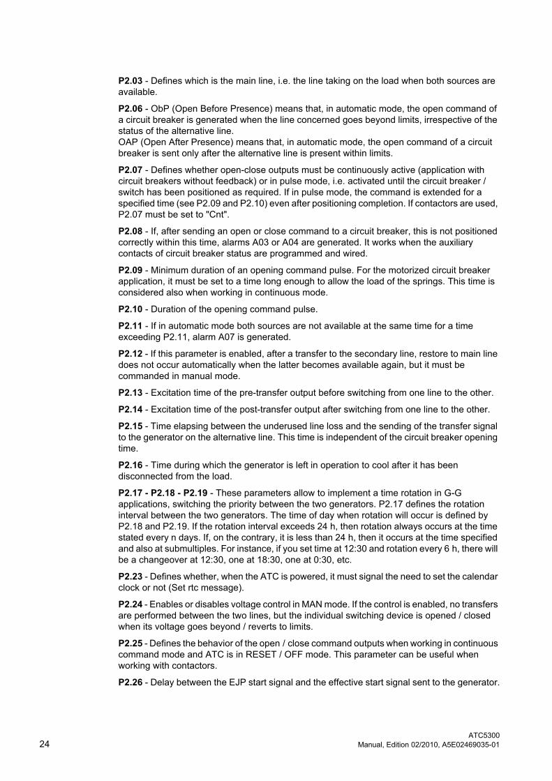
P2.03 - Defines which is the main line, i.e. the line taking on the load when both sources are available.
P2.06 - ObP (Open Before Presence) means that, in automatic mode, the open command of a circuit breaker is generated when the line concerned goes beyond limits, irrespective of the status of the alternative line. OAP (Open After Presence) means that, in automatic mode, the open command of a circuit breaker is sent only after the alternative line is present within limits.
P2.07 - Defines whether open-close outputs must be continuously active (application with circuit breakers without feedback) or in pulse mode, i.e. activated until the circuit breaker /switch has been positioned as required. If in pulse mode, the command is extended for a specified time (see P2.09 and P2.10) even after positioning completion. If contactors are used, P2.07 must be set to "Cnt".
P2.08 - If, after sending an open or close command to a circuit breaker, this is not positioned correctly within this time, alarms A03 or A04 are generated. It works when the auxiliary contacts of circuit breaker status are programmed and wired.
P2.09 - Minimum duration of an opening command pulse. For the motorized circuit breaker application, it must be set to a time long enough to allow the load of the springs. This time is considered also when working in continuous mode.
P2.10 - Duration of the opening command pulse.
P2.11 - If in automatic mode both sources are not available at the same time for a time exceeding P2.11, alarm A07 is generated.
P2.12 - If this parameter is enabled, after a transfer to the secondary line, restore to main line does not occur automatically when the latter becomes available again, but it must be commanded in manual mode.
P2.13 - Excitation time of the pre-transfer output before switching from one line to the other.
P2.14 - Excitation time of the post-transfer output after switching from one line to the other.
P2.15 - Time elapsing between the underused line loss and the sending of the transfer signal to the generator on the alternative line. This time is independent of the circuit breaker opening time.
P2.16 - Time during which the generator is left in operation to cool after it has been disconnected from the load.
P2.17 - P2.18 - P2.19 - These parameters allow to implement a time rotation in G-G applications, switching the priority between the two generators. P2.17 defines the rotation interval between the two generators. The time of day when rotation will occur is defined by P2.18 and P2.19. If the rotation interval exceeds 24 h, then rotation always occurs at the time stated every n days. If, on the contrary, it is less than 24 h, then it occurs at the time specified and also at submultiples. For instance, if you set time at 12:30 and rotation every 6 h, there will be a changeover at 12:30, one at 18:30, one at 0:30, etc.
P2.23 - Defines whether, when the ATC is powered, it must signal the need to set the calendar clock or not (Set rtc message).
P2.24 - Enables or disables voltage control in MAN mode. If the control is enabled, no transfers are performed between the two lines, but the individual switching device is opened / closed when its voltage goes beyond / reverts to limits.
P2.25 - Defines the behavior of the open / close command outputs when working in continuous command mode and ATC is in RESET / OFF mode. This parameter can be useful when working with contactors.
P2.26 - Delay between the EJP start signal and the effective start signal sent to the generator.
Parameter Setup
4.2 Menu Table
ATC5300Manual, Edition 02/2010, A5E02469035-01 25
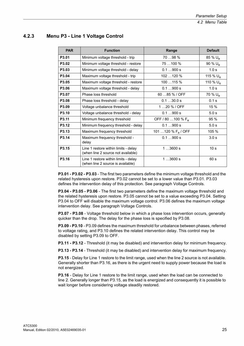
4.2.3 Menu P3 - Line 1 Voltage Control
P3.01 - P3.02 - P3.03 - The first two parameters define the minimum voltage threshold and the related hysteresis upon restore. P3.02 cannot be set to a lower value than P3.01. P3.03 defines the intervention delay of this protection. See paragraph Voltage Controls.
P3.04 - P3.05 - P3.06 - The first two parameters define the maximum voltage threshold and the related hysteresis upon restore. P3.05 cannot be set to a value exceeding P3.04. Setting P3.04 to OFF will disable the maximum voltage control. P3.06 defines the maximum voltage intervention delay. See paragraph Voltage Controls.
P3.07 - P3.08 - Voltage threshold below in which a phase loss intervention occurs, generally quicker than the drop. The delay for the phase loss is specified by P3.08.
P3.09 - P3.10 - P3.09 defines the maximum threshold for unbalance between phases, referred to voltage rating, and P3.10 defines the related intervention delay. This control may be disabled by setting P3.09 to OFF.
P3.11 - P3.12 - Threshold (it may be disabled) and intervention delay for minimum frequency.
P3.13 - P3.14 - Threshold (it may be disabled) and intervention delay for maximum frequency.
P3.15 - Delay for Line 1 restore to the limit range, used when the line 2 source is not available. Generally shorter than P3.16, as there is the urgent need to supply power because the load is not energized.
P3.16 - Delay for Line 1 restore to the limit range, used when the load can be connected to line 2. Generally longer than P3.15, as the load is energized and consequently it is possible to wait longer before considering voltage steadily restored.
PAR Function Range Default
P3.01 Minimum voltage threshold - trip 70 …98 % 85 % Ue
P3.02 Minimum voltage threshold - restore 75 …100 % 90 % Ue
P3.03 Minimum voltage threshold - delay 0.1 …900 s 1.0 s
P3.04 Maximum voltage threshold - trip 102 …120 % 115 % Ue
P3.05 Maximum voltage threshold - restore 100 …115 % 110 % Ue
P3.06 Maximum voltage threshold - delay 0.1 …900 s 1.0 s
P3.07 Phase loss threshold 60 …85 % / OFF 70 % Ue
P3.08 Phase loss threshold - delay 0.1 …30.0 s 0.1 s
P3.09 Voltage unbalance threshold 1 …20 % / OFF 15 %
P3.10 Voltage unbalance threshold - delay 0.1 …900 s 5.0 s
P3.11 Minimum frequency threshold OFF / 80 …100 % Fe 95 %
P3.12 Minimum frequency threshold - delay 0.1 …900 s 5.0 s
P3.13 Maximum frequency threshold 101 …120 % Fe / OFF 105 %
P3.14 Maximum frequency threshold - delay
0.1 …900 s 3.0 s
P3.15 Line 1 restore within limits - delay (when line 2 source not available)
1 …3600 s 10 s
P3.16 Line 1 restore within limits - delay (when line 2 source is available)
1 …3600 s 60 s
Parameter Setup
4.2 Menu Table
ATC530026 Manual, Edition 02/2010, A5E02469035-01
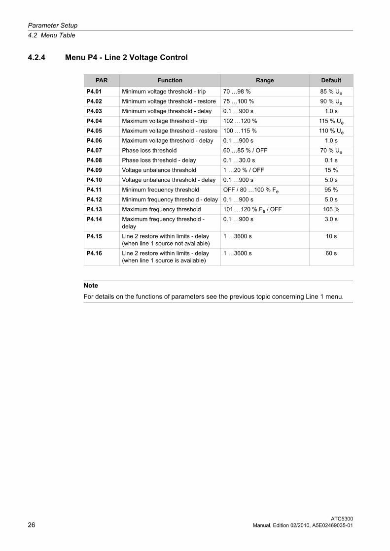
4.2.4 Menu P4 - Line 2 Voltage Control
PAR Function Range Default
P4.01 Minimum voltage threshold - trip 70 …98 % 85 % Ue
P4.02 Minimum voltage threshold - restore 75 …100 % 90 % Ue
P4.03 Minimum voltage threshold - delay 0.1 …900 s 1.0 s
P4.04 Maximum voltage threshold - trip 102 …120 % 115 % Ue
P4.05 Maximum voltage threshold - restore 100 …115 % 110 % Ue
P4.06 Maximum voltage threshold - delay 0.1 …900 s 1.0 s
P4.07 Phase loss threshold 60 …85 % / OFF 70 % Ue
P4.08 Phase loss threshold - delay 0.1 …30.0 s 0.1 s
P4.09 Voltage unbalance threshold 1 …20 % / OFF 15 %
P4.10 Voltage unbalance threshold - delay 0.1 …900 s 5.0 s
P4.11 Minimum frequency threshold OFF / 80 …100 % Fe 95 %
P4.12 Minimum frequency threshold - delay 0.1 …900 s 5.0 s
P4.13 Maximum frequency threshold 101 …120 % Fe / OFF 105 %
P4.14 Maximum frequency threshold - delay
0.1 …900 s 3.0 s
P4.15 Line 2 restore within limits - delay (when line 1 source not available)
1 …3600 s 10 s
P4.16 Line 2 restore within limits - delay (when line 1 source is available)
1 …3600 s 60 s
Note
For details on the functions of parameters see the previous topic concerning Line 1 menu.
Parameter Setup
4.2 Menu Table
ATC5300Manual, Edition 02/2010, A5E02469035-01 27
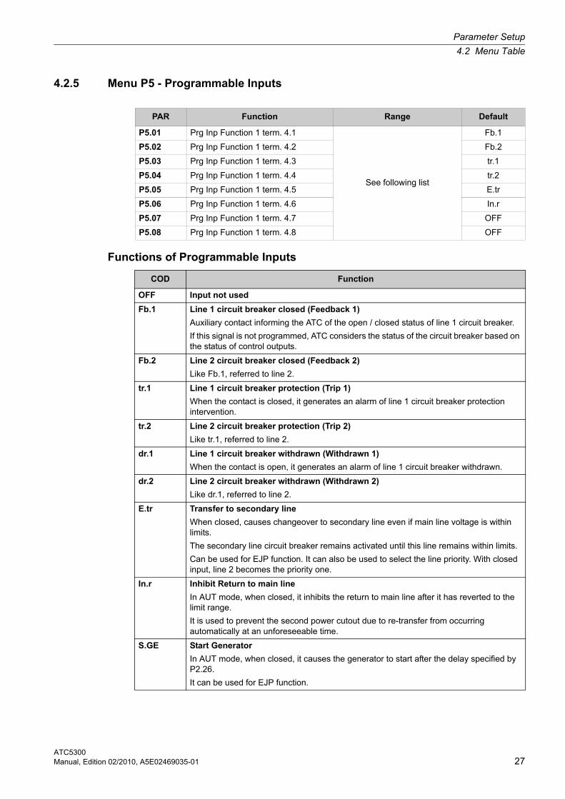
4.2.5 Menu P5 - Programmable Inputs
Functions of Programmable Inputs
PAR Function Range Default
P5.01 Prg Inp Function 1 term. 4.1
See following list
Fb.1
P5.02 Prg Inp Function 1 term. 4.2 Fb.2
P5.03 Prg Inp Function 1 term. 4.3 tr.1
P5.04 Prg Inp Function 1 term. 4.4 tr.2
P5.05 Prg Inp Function 1 term. 4.5 E.tr
P5.06 Prg Inp Function 1 term. 4.6 In.r
P5.07 Prg Inp Function 1 term. 4.7 OFF
P5.08 Prg Inp Function 1 term. 4.8 OFF
COD Function
OFF Input not used
Fb.1 Line 1 circuit breaker closed (Feedback 1)
Auxiliary contact informing the ATC of the open / closed status of line 1 circuit breaker.
If this signal is not programmed, ATC considers the status of the circuit breaker based on the status of control outputs.
Fb.2 Line 2 circuit breaker closed (Feedback 2)
Like Fb.1, referred to line 2.
tr.1 Line 1 circuit breaker protection (Trip 1)
When the contact is closed, it generates an alarm of line 1 circuit breaker protection intervention.
tr.2 Line 2 circuit breaker protection (Trip 2)
Like tr.1, referred to line 2.
dr.1 Line 1 circuit breaker withdrawn (Withdrawn 1)
When the contact is open, it generates an alarm of line 1 circuit breaker withdrawn.
dr.2 Line 2 circuit breaker withdrawn (Withdrawn 2)
Like dr.1, referred to line 2.
E.tr Transfer to secondary line
When closed, causes changeover to secondary line even if main line voltage is within limits.
The secondary line circuit breaker remains activated until this line remains within limits.
Can be used for EJP function. It can also be used to select the line priority. With closed input, line 2 becomes the priority one.
In.r Inhibit Return to main line
In AUT mode, when closed, it inhibits the return to main line after it has reverted to the limit range.
It is used to prevent the second power cutout due to re-transfer from occurring automatically at an unforeseeable time.
S.GE Start Generator
In AUT mode, when closed, it causes the generator to start after the delay specified by P2.26.
It can be used for EJP function.
Parameter Setup
4.2 Menu Table
ATC530028 Manual, Edition 02/2010, A5E02469035-01
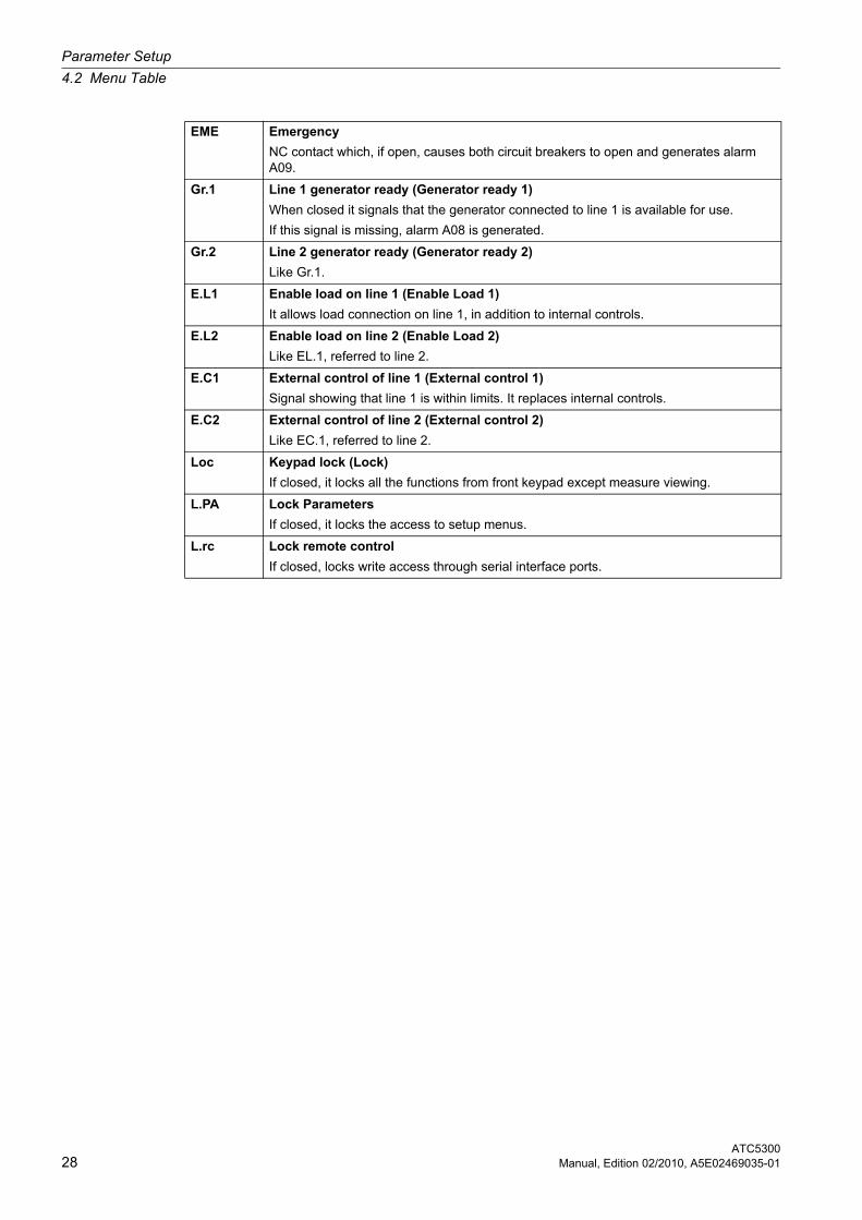
EME Emergency
NC contact which, if open, causes both circuit breakers to open and generates alarm A09.
Gr.1 Line 1 generator ready (Generator ready 1)
When closed it signals that the generator connected to line 1 is available for use.
If this signal is missing, alarm A08 is generated.
Gr.2 Line 2 generator ready (Generator ready 2)
Like Gr.1.
E.L1 Enable load on line 1 (Enable Load 1)
It allows load connection on line 1, in addition to internal controls.
E.L2 Enable load on line 2 (Enable Load 2)
Like EL.1, referred to line 2.
E.C1 External control of line 1 (External control 1)
Signal showing that line 1 is within limits. It replaces internal controls.
E.C2 External control of line 2 (External control 2)
Like EC.1, referred to line 2.
Loc Keypad lock (Lock)
If closed, it locks all the functions from front keypad except measure viewing.
L.PA Lock Parameters
If closed, it locks the access to setup menus.
L.rc Lock remote control
If closed, locks write access through serial interface ports.
Parameter Setup
4.2 Menu Table
ATC5300Manual, Edition 02/2010, A5E02469035-01 29
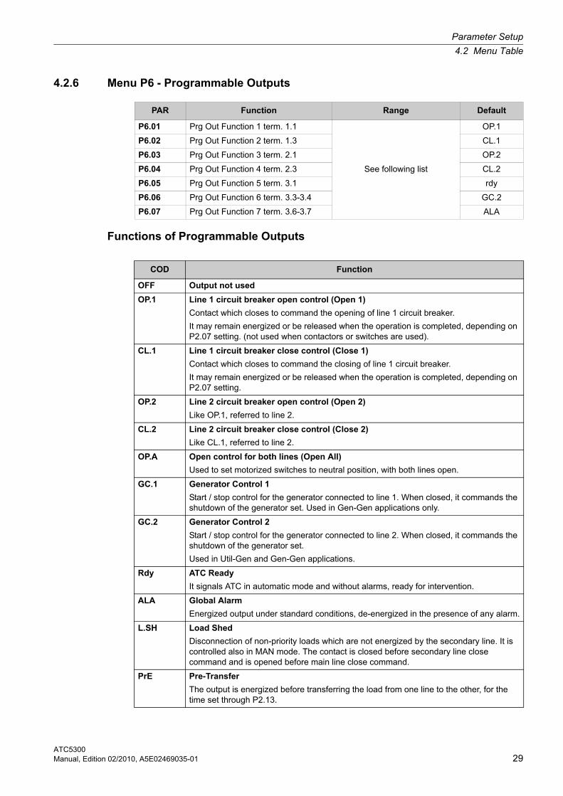
4.2.6 Menu P6 - Programmable Outputs
Functions of Programmable Outputs
PAR Function Range Default
P6.01 Prg Out Function 1 term. 1.1
See following list
OP.1
P6.02 Prg Out Function 2 term. 1.3 CL.1
P6.03 Prg Out Function 3 term. 2.1 OP.2
P6.04 Prg Out Function 4 term. 2.3 CL.2
P6.05 Prg Out Function 5 term. 3.1 rdy
P6.06 Prg Out Function 6 term. 3.3-3.4 GC.2
P6.07 Prg Out Function 7 term. 3.6-3.7 ALA
COD Function
OFF Output not used
OP.1 Line 1 circuit breaker open control (Open 1)
Contact which closes to command the opening of line 1 circuit breaker.
It may remain energized or be released when the operation is completed, depending on P2.07 setting. (not used when contactors or switches are used).
CL.1 Line 1 circuit breaker close control (Close 1)
Contact which closes to command the closing of line 1 circuit breaker.
It may remain energized or be released when the operation is completed, depending on P2.07 setting.
OP.2 Line 2 circuit breaker open control (Open 2)
Like OP.1, referred to line 2.
CL.2 Line 2 circuit breaker close control (Close 2)
Like CL.1, referred to line 2.
OP.A Open control for both lines (Open All)
Used to set motorized switches to neutral position, with both lines open.
GC.1 Generator Control 1
Start / stop control for the generator connected to line 1. When closed, it commands the shutdown of the generator set. Used in Gen-Gen applications only.
GC.2 Generator Control 2
Start / stop control for the generator connected to line 2. When closed, it commands the shutdown of the generator set.
Used in Util-Gen and Gen-Gen applications.
Rdy ATC Ready
It signals ATC in automatic mode and without alarms, ready for intervention.
ALA Global Alarm
Energized output under standard conditions, de-energized in the presence of any alarm.
L.SH Load Shed
Disconnection of non-priority loads which are not energized by the secondary line. It is controlled also in MAN mode. The contact is closed before secondary line close command and is opened before main line close command.
PrE Pre-Transfer
The output is energized before transferring the load from one line to the other, for the time set through P2.13.

Parameter Setup
4.2 Menu Table
ATC530030 Manual, Edition 02/2010, A5E02469035-01
PoS Post-Transfer
The output is energized after transferring the load from one line to the other, for the time set through P2.14.
L1.S Line 1 Status
The output is energized when there are all the conditions to connect load to line 1.
L2.S Line 2 Status
The output is energized when there are all the conditions to connect load to line 2.
Parameter Setup
4.2 Menu Table
ATC5300Manual, Edition 02/2010, A5E02469035-01 31
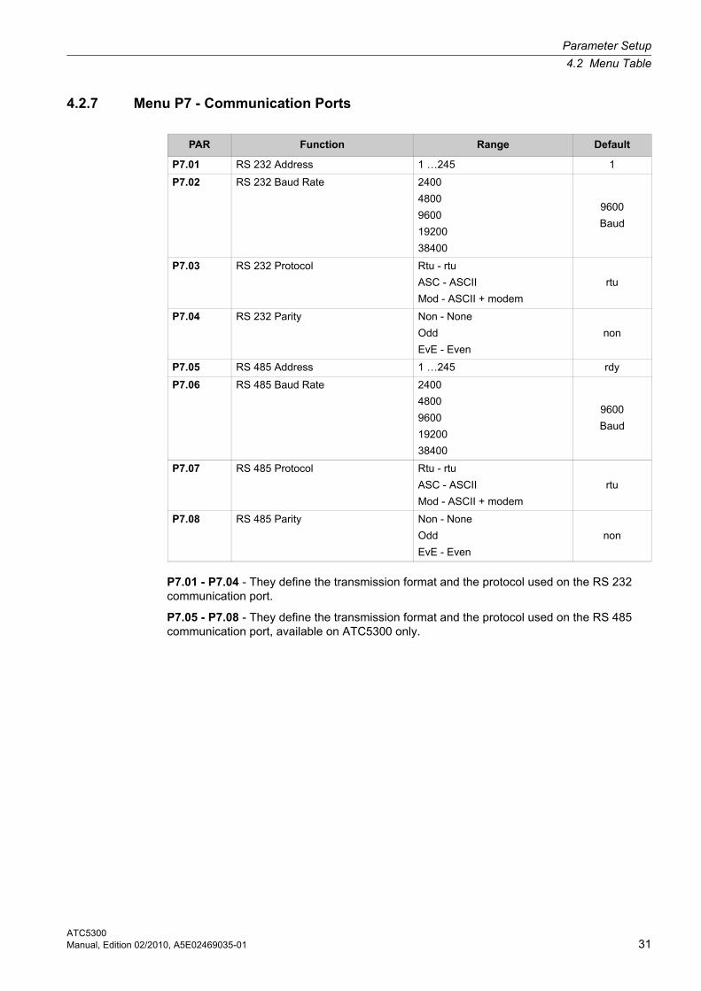
4.2.7 Menu P7 - Communication Ports
P7.01 - P7.04 - They define the transmission format and the protocol used on the RS 232 communication port.
P7.05 - P7.08 - They define the transmission format and the protocol used on the RS 485 communication port, available on ATC5300 only.
PAR Function Range Default
P7.01 RS 232 Address 1 …245 1
P7.02 RS 232 Baud Rate 2400
4800
9600
19200
38400
9600
Baud
P7.03 RS 232 Protocol Rtu - rtu
ASC - ASCII
Mod - ASCII + modem
rtu
P7.04 RS 232 Parity Non - None
Odd
EvE - Even
non
P7.05 RS 485 Address 1 …245 rdy
P7.06 RS 485 Baud Rate 2400
4800
9600
19200
38400
9600
Baud
P7.07 RS 485 Protocol Rtu - rtu
ASC - ASCII
Mod - ASCII + modem
rtu
P7.08 RS 485 Parity Non - None
Odd
EvE - Even
non
Parameter Setup
4.2 Menu Table
ATC530032 Manual, Edition 02/2010, A5E02469035-01
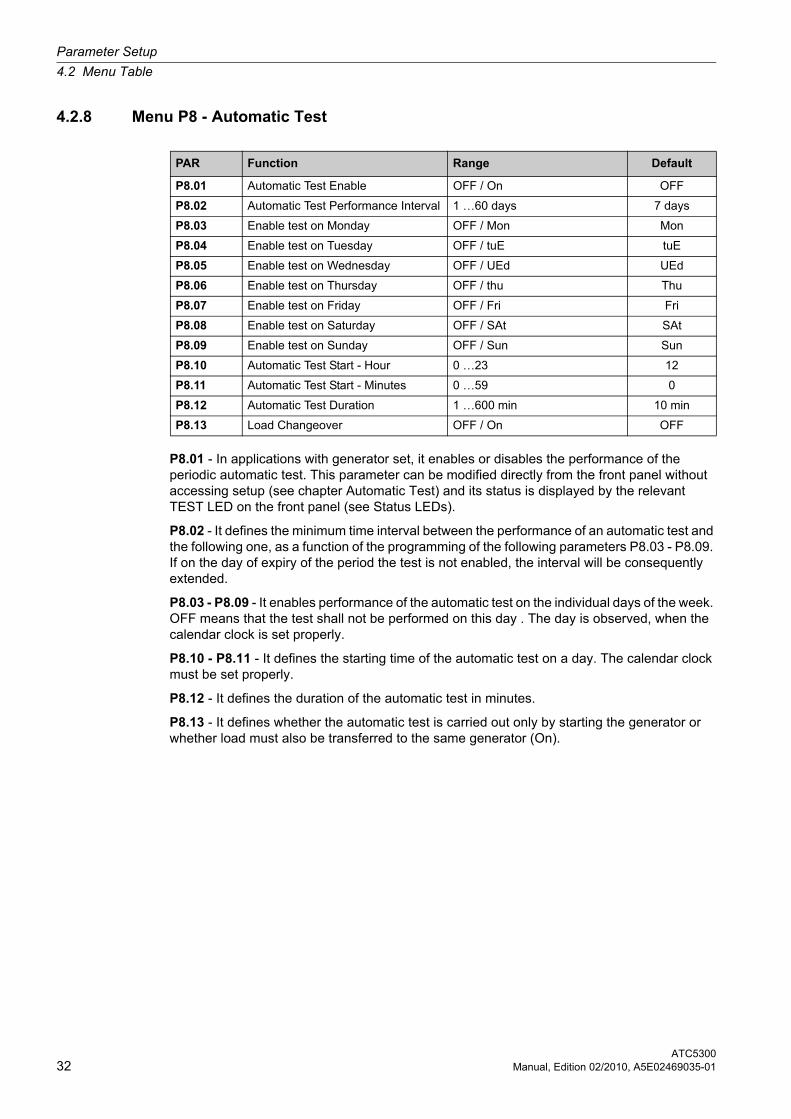
4.2.8 Menu P8 - Automatic Test
P8.01 - In applications with generator set, it enables or disables the performance of the periodic automatic test. This parameter can be modified directly from the front panel without accessing setup (see chapter Automatic Test) and its status is displayed by the relevant TEST LED on the front panel (see Status LEDs).
P8.02 - It defines the minimum time interval between the performance of an automatic test and the following one, as a function of the programming of the following parameters P8.03 - P8.09. If on the day of expiry of the period the test is not enabled, the interval will be consequently extended.
P8.03 - P8.09 - It enables performance of the automatic test on the individual days of the week. OFF means that the test shall not be performed on this day . The day is observed, when the calendar clock is set properly.
P8.10 - P8.11 - It defines the starting time of the automatic test on a day. The calendar clock must be set properly.
P8.12 - It defines the duration of the automatic test in minutes.
P8.13 - It defines whether the automatic test is carried out only by starting the generator or whether load must also be transferred to the same generator (On).
PAR Function Range Default
P8.01 Automatic Test Enable OFF / On OFF
P8.02 Automatic Test Performance Interval 1 …60 days 7 days
P8.03 Enable test on Monday OFF / Mon Mon
P8.04 Enable test on Tuesday OFF / tuE tuE
P8.05 Enable test on Wednesday OFF / UEd UEd
P8.06 Enable test on Thursday OFF / thu Thu
P8.07 Enable test on Friday OFF / Fri Fri
P8.08 Enable test on Saturday OFF / SAt SAt
P8.09 Enable test on Sunday OFF / Sun Sun
P8.10 Automatic Test Start - Hour 0 …23 12
P8.11 Automatic Test Start - Minutes 0 …59 0
P8.12 Automatic Test Duration 1 …600 min 10 min
P8.13 Load Changeover OFF / On OFF
ATC5300Operating Instructions, Edition 02/2010, A5E02469035-01 33
Wiring Diagrams 5Wiring Diagrams
5.1 General Connection
5.1.1 Motorized Circuit Breakers Control
Code Description
Q1 Circuit Breaker (main line)Q2 Circuit Breaker (secondary line)
QF1 / QF2 Line FuseK1 / K2 Contactors (switch power supply between main and secondary line)
Wiring Diagrams
5.1 General Connection
ATC530034 Operating Instructions, Edition 02/2010, A5E02469035-01
5.1.2 Motorized Changeover Switch Control
Table: General Settings Table: Input-Functions Table: Output-Functions
Parameter Setting Terminal Parameter Setting Terminal Parameter Setting
P2.07 PUL 4.1 P5.01 Fb.1 1.1 P6.01 OP.1
4.2 P5.02 Fb.2 1.3 P6.02 CL.1
4.3 P5.03 Tr.1 2.1 P6.03 OP.2
4.4 P5.04 Tr.2 2.3 P6.04 CL.2
Code Description
Q1 Changeover Switch
QF1 / QF2 Line Fuse
K1 / K2 Contactors (switch power supply between main and secondary line)
Table: General Settings Table: Input-Functions Table: Output-Functions
Parameter Setting Terminal Parameter Setting Terminal Parameter Setting
P2.07 PUL 4.1 P5.01 Fb.1 1.1 P6.01 CL.1
4.2 P5.02 Fb.2 1.3 P6.02 OP.A
2.1 P6.03 CL.2
8.1
Wiring Diagrams
5.1 General Connection
ATC5300Operating Instructions, Edition 02/2010, A5E02469035-01 35
5.1.3 Contactors Control
Code Description
K1 / K2 Line Contactors
QF1 / QF2 Line Fuse
K3 / K4 Contactors (switch power supply between main and secondary line)
Table: General Settings Table: Input-Functions Table: Output-Functions
Parameter Setting Terminal Parameter Setting Terminal Parameter Setting
P2.07 Cnt 4.1 P5.01 Fb.1 1.1 P6.01 CL.1
4.2 P5.02 Fb.2 2.1 P6.03 CL.2
1.1
1.2
1.3
2.1
2.2
2.3
3.1
3.2
3.3
3.4
3.5
3.8
3.7
3.6
4.5
4.4
4.3
4.2
4.1
4.6
4.7
4.8
5.2
5.1
5.3
9.4
9.3
9.2
9.1
8.4
8.3
8.2
8.1
7.1
7.2
A 6.3
TR 6.4
B 6.2
SG 6.1
DIGITAL INPUTS
RS232
RS485
SUPPLYDC
+ _ _
L1 L2 L3 NLINE 1
L1LINE 2
L3L2 N
L2L1 L3 NLOAD
K2K1
K4
K4K3
K3
K4 K4 K3 K3
ATC5300
QF1
QF2
K1 K2
K2 K1
K1 K2
ATC530036 Operating Instructions, Edition 02/2010, A5E02469035-01
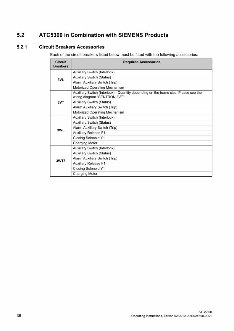
5.2 ATC5300 in Combination with SIEMENS Products
5.2.1 Circuit Breakers Accessories
Each of the circuit breakers listed below must be fitted with the following accessories:
Circuit Breakers
Required Accessories
3VL
Auxiliary Switch (Interlock)
Auxiliary Switch (Status)
Alarm Auxiliary Switch (Trip)
Motorized Operating Mechanism
3VT
Auxiliary Switch (Interlock) - Quantity depending on the frame size. Please see the wiring diagram "SENTRON 3VT".
Auxiliary Switch (Status)
Alarm Auxiliary Switch (Trip)
Motorized Operating Mechanism
3WL
Auxiliary Switch (Interlock)
Auxiliary Switch (Status)
Alarm Auxiliary Switch (Trip)
Auxiliary Release F1
Closing Solenoid Y1
Charging Motor
3WT8
Auxiliary Switch (Interlock)
Auxiliary Switch (Status)
Alarm Auxiliary Switch (Trip)
Auxiliary Release F1
Closing Solenoid Y1
Charging Motor
Wiring Diagrams
5.2 ATC5300 in Combination with SIEMENS Products
ATC5300Operating Instructions, Edition 02/2010, A5E02469035-01 37
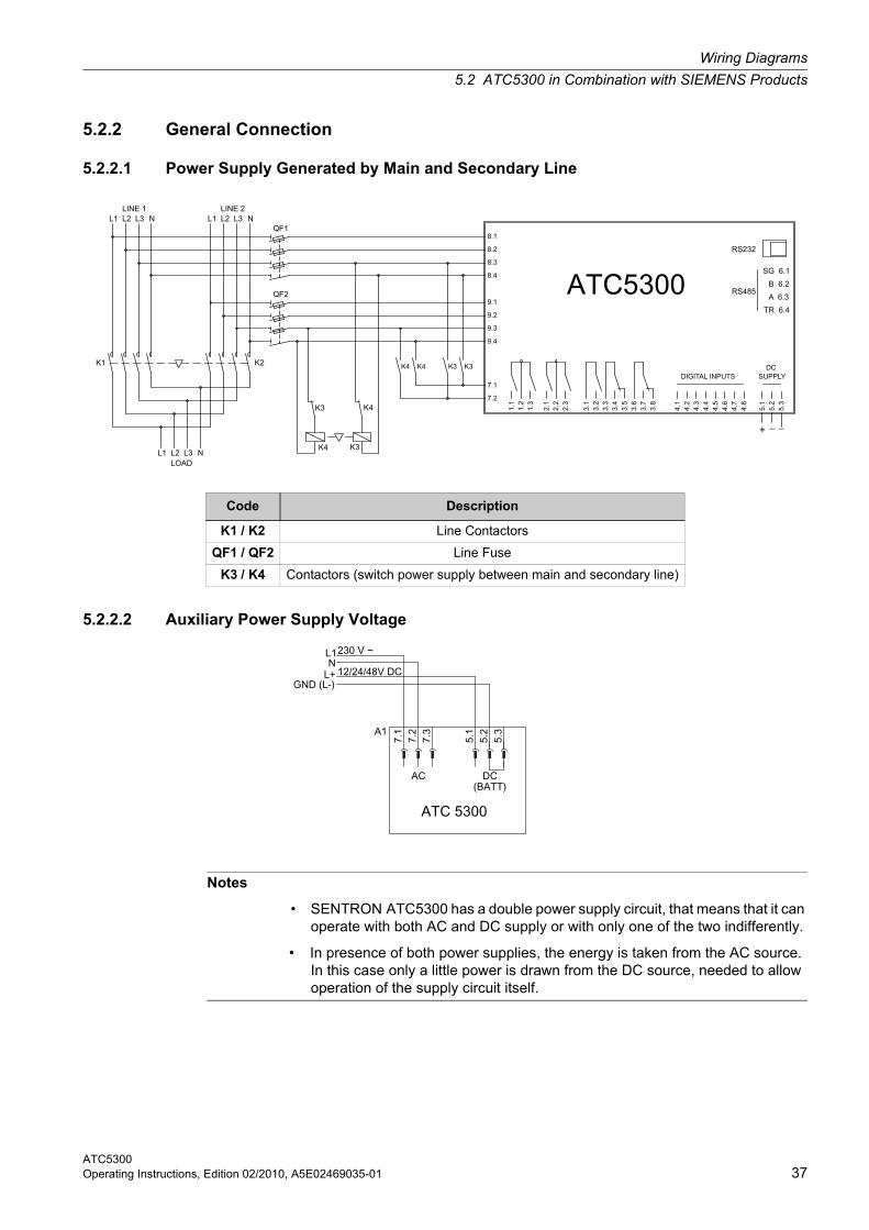
5.2.2 General Connection
5.2.2.1 Power Supply Generated by Main and Secondary Line
5.2.2.2 Auxiliary Power Supply Voltage
Code Description
K1 / K2 Line Contactors
QF1 / QF2 Line Fuse
K3 / K4 Contactors (switch power supply between main and secondary line)
Notes
• SENTRON ATC5300 has a double power supply circuit, that means that it can operate with both AC and DC supply or with only one of the two indifferently.
• In presence of both power supplies, the energy is taken from the AC source. In this case only a little power is drawn from the DC source, needed to allow operation of the supply circuit itself.
Wiring Diagrams
5.2 ATC5300 in Combination with SIEMENS Products
ATC530038 Operating Instructions, Edition 02/2010, A5E02469035-01
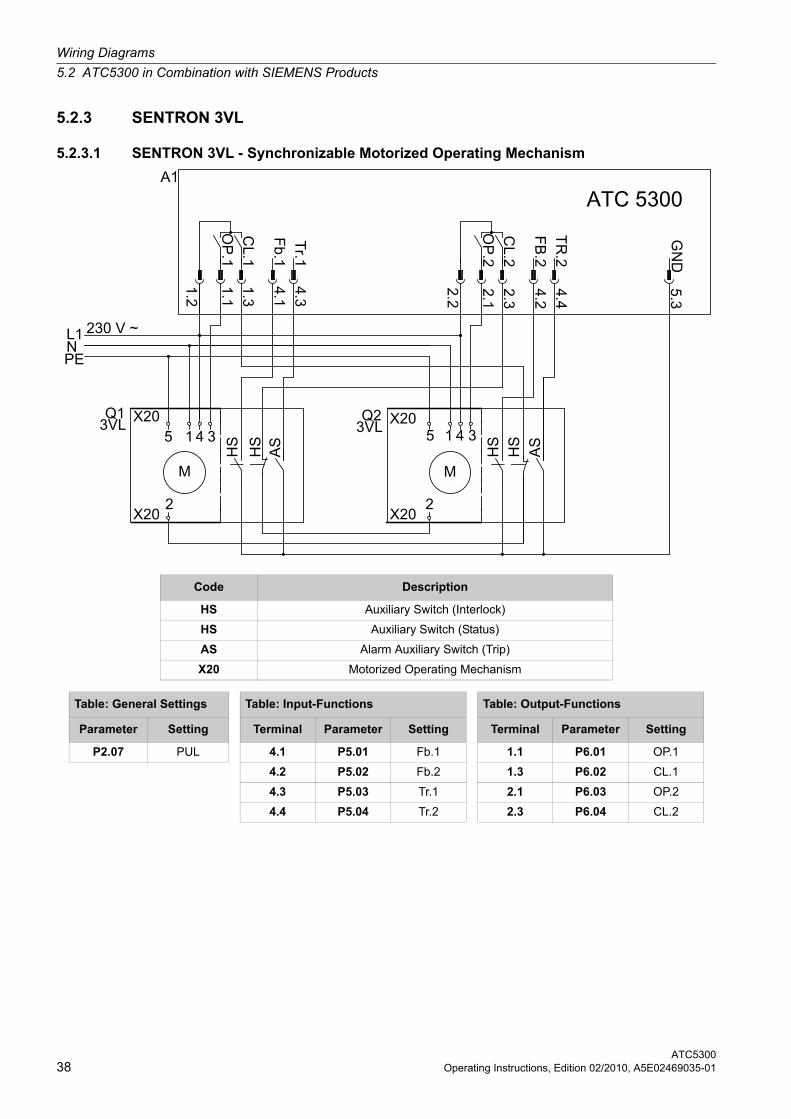
5.2.3 SENTRON 3VL
5.2.3.1 SENTRON 3VL - Synchronizable Motorized Operating Mechanism
Code Description
HS Auxiliary Switch (Interlock)
HS Auxiliary Switch (Status)
AS Alarm Auxiliary Switch (Trip)
X20 Motorized Operating Mechanism
Table: General Settings Table: Input-Functions Table: Output-Functions
Parameter Setting Terminal Parameter Setting Terminal Parameter Setting
P2.07 PUL 4.1 P5.01 Fb.1 1.1 P6.01 OP.1
4.2 P5.02 Fb.2 1.3 P6.02 CL.1
4.3 P5.03 Tr.1 2.1 P6.03 OP.2
4.4 P5.04 Tr.2 2.3 P6.04 CL.2
Wiring Diagrams
5.2 ATC5300 in Combination with SIEMENS Products
ATC5300Operating Instructions, Edition 02/2010, A5E02469035-01 39
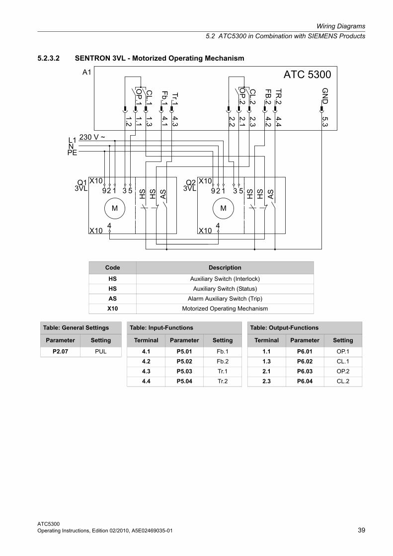
5.2.3.2 SENTRON 3VL - Motorized Operating Mechanism
Code Description
HS Auxiliary Switch (Interlock)
HS Auxiliary Switch (Status)
AS Alarm Auxiliary Switch (Trip)
X10 Motorized Operating Mechanism
Table: General Settings Table: Input-Functions Table: Output-Functions
Parameter Setting Terminal Parameter Setting Terminal Parameter Setting
P2.07 PUL 4.1 P5.01 Fb.1 1.1 P6.01 OP.1
4.2 P5.02 Fb.2 1.3 P6.02 CL.1
4.3 P5.03 Tr.1 2.1 P6.03 OP.2
4.4 P5.04 Tr.2 2.3 P6.04 CL.2
Wiring Diagrams
5.2 ATC5300 in Combination with SIEMENS Products
ATC530040 Operating Instructions, Edition 02/2010, A5E02469035-01
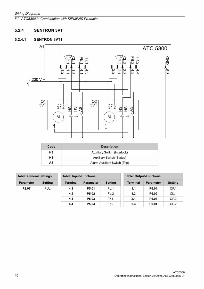
5.2.4 SENTRON 3VT
5.2.4.1 SENTRON 3VT1
Code Description
HS Auxiliary Switch (Interlock)
HS Auxiliary Switch (Status)
AS Alarm Auxiliary Switch (Trip)
Table: General Settings Table: Input-Functions Table: Output-Functions
Parameter Setting Terminal Parameter Setting Terminal Parameter Setting
P2.07 PUL 4.1 P5.01 Fb.1 1.1 P6.01 OP.1
4.2 P5.02 Fb.2 1.3 P6.02 CL.1
4.3 P5.03 Tr.1 2.1 P6.03 OP.2
4.4 P5.04 Tr.2 2.3 P6.04 CL.2
Wiring Diagrams
5.2 ATC5300 in Combination with SIEMENS Products
ATC5300Operating Instructions, Edition 02/2010, A5E02469035-01 41
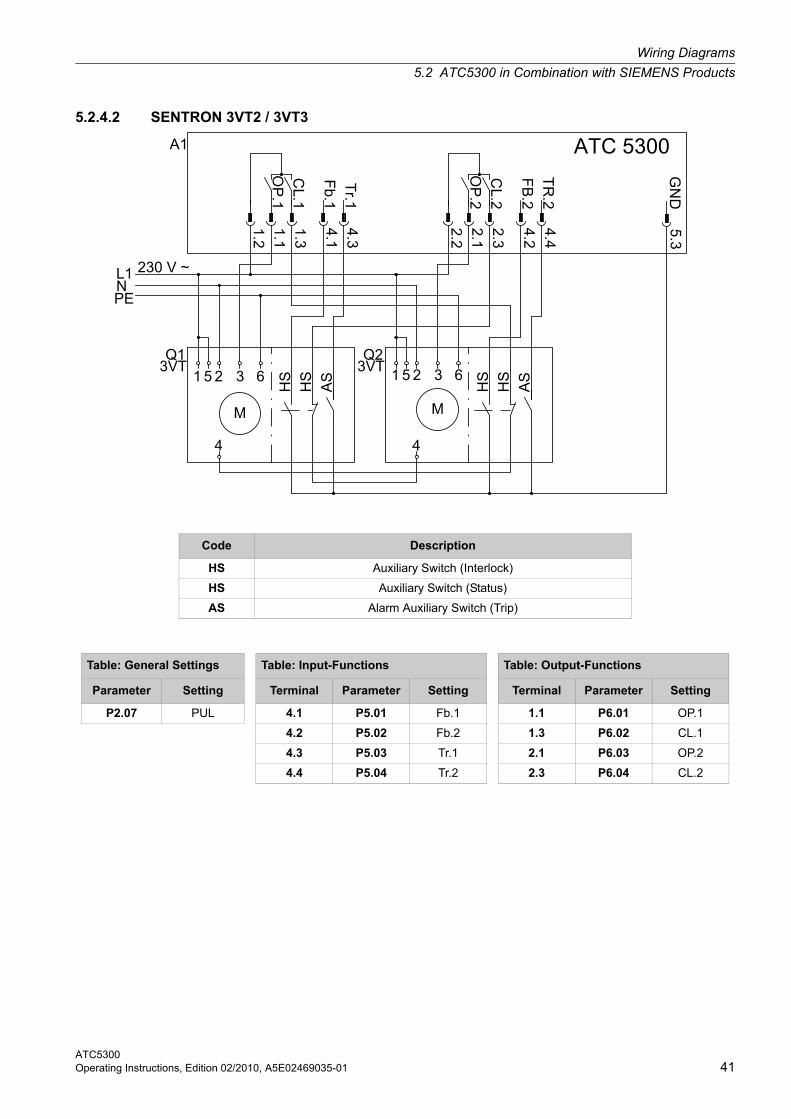
5.2.4.2 SENTRON 3VT2 / 3VT3
Code Description
HS Auxiliary Switch (Interlock)
HS Auxiliary Switch (Status)
AS Alarm Auxiliary Switch (Trip)
Table: General Settings Table: Input-Functions Table: Output-Functions
Parameter Setting Terminal Parameter Setting Terminal Parameter Setting
P2.07 PUL 4.1 P5.01 Fb.1 1.1 P6.01 OP.1
4.2 P5.02 Fb.2 1.3 P6.02 CL.1
4.3 P5.03 Tr.1 2.1 P6.03 OP.2
4.4 P5.04 Tr.2 2.3 P6.04 CL.2
Wiring Diagrams
5.2 ATC5300 in Combination with SIEMENS Products
ATC530042 Operating Instructions, Edition 02/2010, A5E02469035-01
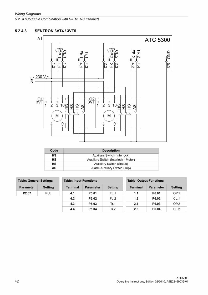
5.2.4.3 SENTRON 3VT4 / 3VT5
Code Description
HS Auxiliary Switch (Interlock)HS Auxiliary Switch (Interlock - Motor)HS Auxiliary Switch (Status)AS Alarm Auxiliary Switch (Trip)
Table: General Settings Table: Input-Functions Table: Output-Functions
Parameter Setting Terminal Parameter Setting Terminal Parameter Setting
P2.07 PUL 4.1 P5.01 Fb.1 1.1 P6.01 OP.1
4.2 P5.02 Fb.2 1.3 P6.02 CL.1
4.3 P5.03 Tr.1 2.1 P6.03 OP.2
4.4 P5.04 Tr.2 2.3 P6.04 CL.2
Wiring Diagrams
5.2 ATC5300 in Combination with SIEMENS Products
ATC5300Operating Instructions, Edition 02/2010, A5E02469035-01 43
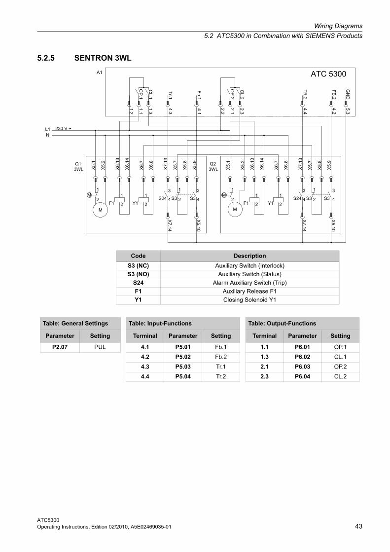
5.2.5 SENTRON 3WL
Code Description
S3 (NC) Auxiliary Switch (Interlock)
S3 (NO) Auxiliary Switch (Status)
S24 Alarm Auxiliary Switch (Trip)
F1 Auxiliary Release F1
Y1 Closing Solenoid Y1
Table: General Settings Table: Input-Functions Table: Output-Functions
Parameter Setting Terminal Parameter Setting Terminal Parameter Setting
P2.07 PUL 4.1 P5.01 Fb.1 1.1 P6.01 OP.1
4.2 P5.02 Fb.2 1.3 P6.02 CL.1
4.3 P5.03 Tr.1 2.1 P6.03 OP.2
4.4 P5.04 Tr.2 2.3 P6.04 CL.2
Wiring Diagrams
5.2 ATC5300 in Combination with SIEMENS Products
ATC530044 Operating Instructions, Edition 02/2010, A5E02469035-01
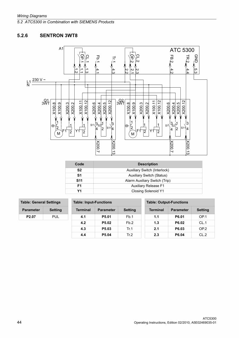
5.2.6 SENTRON 3WT8
Code Description
S2 Auxiliary Switch (Interlock)
S1 Auxiliary Switch (Status)
S11 Alarm Auxiliary Switch (Trip)
F1 Auxiliary Release F1
Y1 Closing Solenoid Y1
Table: General Settings Table: Input-Functions Table: Output-Functions
Parameter Setting Terminal Parameter Setting Terminal Parameter Setting
P2.07 PUL 4.1 P5.01 Fb.1 1.1 P6.01 OP.1
4.2 P5.02 Fb.2 1.3 P6.02 CL.1
4.3 P5.03 Tr.1 2.1 P6.03 OP.2
4.4 P5.04 Tr.2 2.3 P6.04 CL.2
Wiring Diagrams
5.3 Mechanical Dimensions and Panel Cut-Out
ATC5300Operating Instructions, Edition 02/2010, A5E02469035-01 45
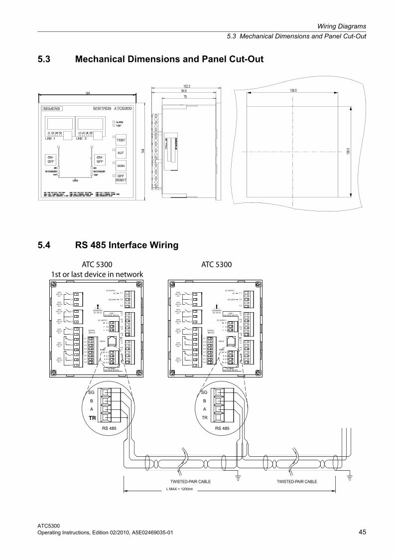
5.3 Mechanical Dimensions and Panel Cut-Out
5.4 RS 485 Interface Wiring
VOLTAGE INPUTSLINE 2
VOLTAGE INPUTSLINE 2
LINE 1VOLTAGE INPUTS VOLTAGE INPUTS
LINE 1
AC SUPPLY AC SUPPLY
TR
RS 485
SG
B
A
TR
RS 485
SG
B
A
TWISTED-PAIR CABLE TWISTED-PAIR CABLE
ATC 53001st or last device in network
ATC 5300
INPUTSDIGITAL
3.3
250V 5A
250V 5AAC1
B300
AC1
B300
3.6
3.8
3.7
3.5
3.4
4.4
4.2
4.3
4.6
4.5
4.7
4.8
250V 5A
250V 12A
250V 12A
250V 5A
250V 5A
2.1
AC1
B300
B300
AC1
AC1
3.1
3.2
2.2
2.3
B300
AC1
B300
B300
AC1
1.3
1.2
1.1
4.19.1
RS485
TR 6.4
A 6.3
B 6.2
SG 6.1
RS232
9.3
9.4N
L3
9.2L2
L1
220-240V
0V
+DC SUPPLY
-- 5.3
5.2
5.1
8.4N
L38.3
8.2L2
L18.1
7.3
7.2
7.1
3.2
3.7250V 5AAC1
3.8
B300
3.6
3.5
B300
AC1250V 5A
3.3
3.4
2.3250V 5A
B300
AC1250V 5A
AC1
3.1
B300
B300
AC1250V 12A
2.2
2.1
1.1250V 12A
B300250V 5A
AC1
AC1
1.3
1.2
B300
N8.4
4.8 TR 6.4
4.6
4.7
4.5
4.4
4.2
4.3
4.1
RS485
B 6.2
A 6.3
SG 6.1
RS232
9.4N
9.2
9.3L3
L2
9.1L1
220-240V
DIGITALINPUTS
+DC SUPPLY
5.2-- 5.3
5.1L2
8.3L3
L1
8.2
8.1
7.3
7.2
0V 7.1
100-690VAC50 / 60 Hz 50 / 60 Hz
100-690VAC
L MAX = 1200mt
Wiring Diagrams
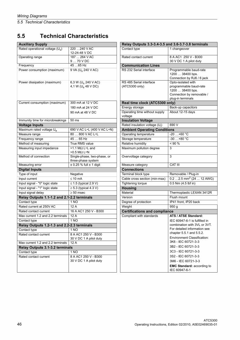
5.5 Technical Characteristics
ATC530046 Operating Instructions, Edition 02/2010, A5E02469035-01
5.5 Technical CharacteristicsAuxiliary Supply Relay Outputs 3.3-3.4-3.5 and 3.6-3.7-3.8 terminalsRated operational voltage (Us) 220 …240 V AC
12-24-48 V DCContact type 1 changeover
Operating range 187 ... 264 V AC 9 … 70 V DC
Rated contact current 8 A AC1 250 V - B300 30 V DC 1 A pilot duty
Frequency 45 …65 Hz Communication LinesPower consumption (maximum) 9 VA (Us 240 V AC) RS 232 Serial interface Programmable baud-rate
1200 … 38400 bps. Connection by RJ6 / 6 jack
Power dissipation (maximum) 6,3 W (Us 240 V AC) 4,1 W (Us 48 V DC)
RS 485 Serial interface (ATC5300 only)
Opto-isolated with programmable baud-rate 1200 … 38400 bps. Connection by removable / plug-in terminals
Current consumption (maximum) 300 mA at 12 V DC 180 mA at 24 V DC
90 mA at 48 V DC
Real time clock (ATC5300 only)Energy storage Back-up capacitors
Operating time without supply voltage
About 12-15 days
Immunity time for microbreakings 50 ms Insulation VoltageVoltage Inputs Rated insulation voltage (Ui) 690 V
Maximum rated voltage Ue 690 V AC L-L (400 V AC L-N) Ambient Operating ConditionsMeasure range 80 … 800 V AC L-L Operating temperature -20 …+60 °C
Frequency range 45 … 65 Hz Storage temperature -30 …+80 °C
Method of measuring True RMS value Relative humidity < 90 %
Measuring input impedance >1.1 MΩ L-L and >0.5 MΩ L-N
Maximum pollution degree 3
Method of connection Single-phase, two-phase, or three-phase system
Overvoltage category 3
Measuring error ± 0.25 % full ± 1 digit Measure category CAT III
Digital Inputs ConnectionsType of input Negative Terminal block type Removable / Plug-in
Input current ≤ 10 mA Cable cross section (min-max) 0.2 …2.5 mm2 (24 ... 12 AWG)
Input signal - "0" logic state ≤ 1.5 (typical 2.9 V) Tightening torque 0.5 Nm (4.5 lbf in)
Input signal - "1" logic state ≥ 5.3 (typical 4.3 V) HousingInput signal delay ≥ 50 msec Material Thermoplastic LEXAN 3412R
Relay Outputs 1.1-1.2 and 2.1-2.2 terminals Version Flush mount
Contact type 1 NO Degree of protection IP41 front, IP20 back
Rated current at 250V AC 12 A Weight 950 g
Rated contact current 16 A AC1 250 V - B300 Certifications and complianceMax current 1.2 and 2.2 terminals 12 A Compliant with standards ATS / ATSE Standard:
IEC 60947-6-1 is fulfilled in combination with 3VL or 3VT. For detailed information see chapter 5.5.1 and 5.5.2.
Environment Classification:3K6 - IEC 60721-3-3
3B2 - IEC 60721-3-3
3C3 - IEC 60721-3-3
3S2 - IEC 60721-3-3
3M6 - IEC 60721-3-3
EMC Standard: according to IEC 60947-6-1
Contact type 1 NO
Relay Outputs 1.2-1.3 and 2.2-2.3 terminalsContact type 1 NO
Rated contact current 8 A AC1 250 V - B300 30 V DC 1 A pilot duty
Max current 1.2 and 2.2 terminals 12 A
Relay Outputs 3.1-3.2 terminalsContact type 1 NO
Rated contact current 8 A AC1 250 V - B300 30 V DC 1 A pilot duty
Wiring Diagrams
5.5 Technical Characteristics
ATC5300Operating Instructions, Edition 02/2010, A5E02469035-01 47
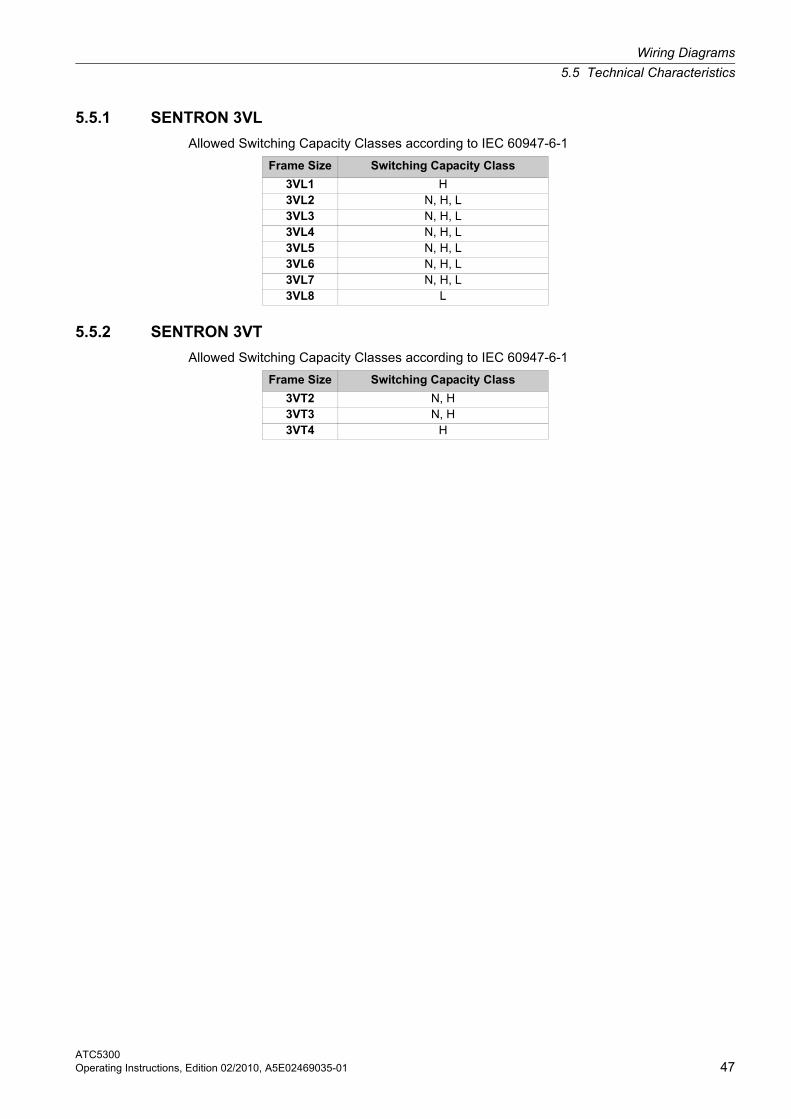
5.5.1 SENTRON 3VL
Allowed Switching Capacity Classes according to IEC 60947-6-1
5.5.2 SENTRON 3VT
Allowed Switching Capacity Classes according to IEC 60947-6-1
Frame Size Switching Capacity Class
3VL1 H3VL2 N, H, L3VL3 N, H, L3VL4 N, H, L3VL5 N, H, L3VL6 N, H, L3VL7 N, H, L3VL8 L
Frame Size Switching Capacity Class
3VT2 N, H3VT3 N, H3VT4 H

Wiring Diagrams
5.5 Technical Characteristics
ATC530048 Operating Instructions, Edition 02/2010, A5E02469035-01
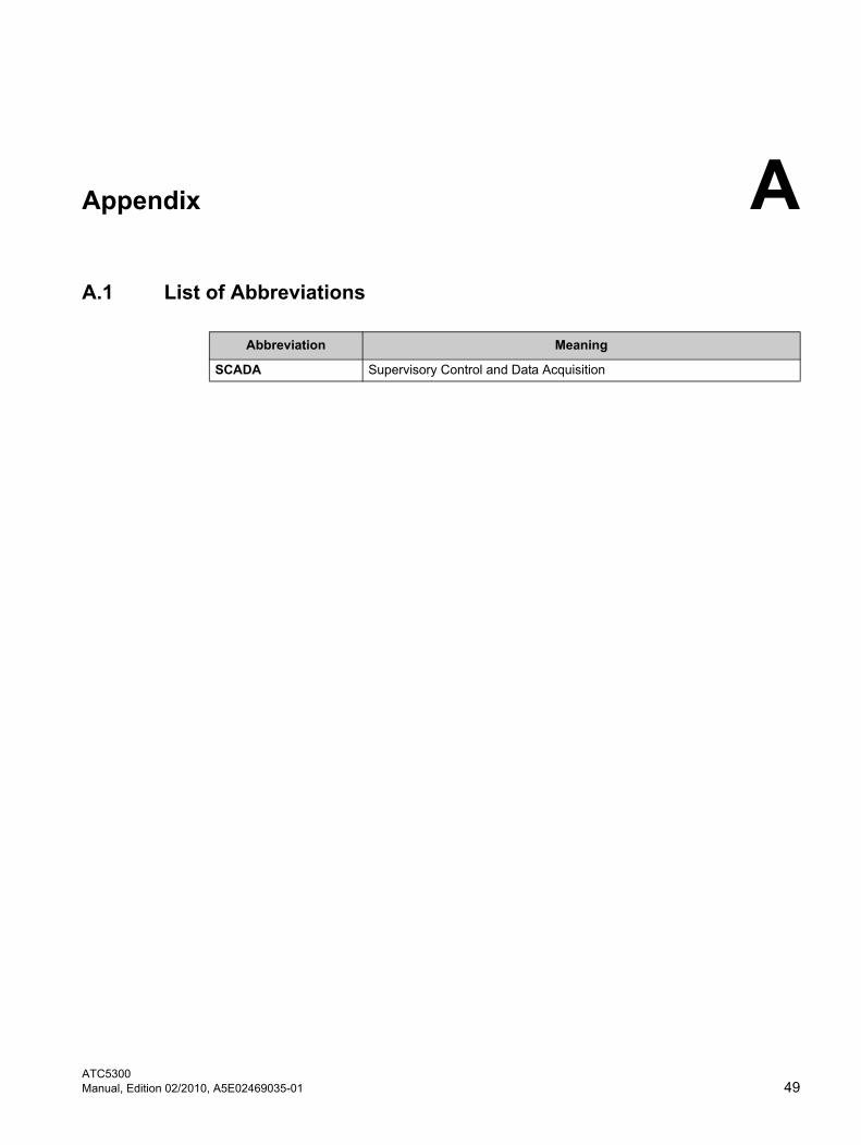
ATC5300Manual, Edition 02/2010, A5E02469035-01 49
Appendix AAppendix
A.1 List of Abbreviations
Abbreviation Meaning
SCADA Supervisory Control and Data Acquisition

Appendix
ATC530050 Manual, Edition 02/2010, A5E02469035-01