Embed Size (px)
Citation preview
www.powers.com 1
aD
hesiV
e a
nch
or
s
GeNeRAL INFoRMATIoN
TECH
MAN
UAL
– AD
HESI
VE A
NCH
ORS
©20
15 P
OW
ERS
VO
LUM
E 1
– 9/
2015
– R
EV. G
Section contentS
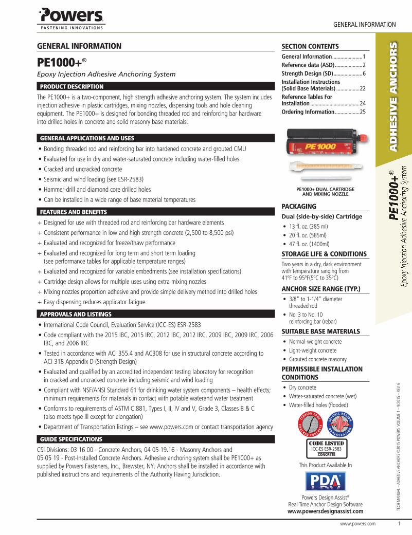
Pe1000+ dual cartridge and mixing nozzle
packagIngdual (side-by-side) cartridge
• 13 fl. oz. (385 ml)• 20 fl. oz. (585ml)• 47 fl. oz. (1400ml)
storage lIFe & condItIonsTwo years in a dry, dark environment with temperature ranging from 41ºF to 95ºF(5ºC to 35ºC)
anchor sIze range (typ.)• 3/8" to 1-1/4" diameter
threaded rod• No. 3 to No. 10
reinforcing bar (rebar)
suItable base materIals• Normal-weight concrete• Light-weight concrete• Grouted concrete masonry
permIssIble InstallatIon condItIons• Dry concrete• Water-saturated concrete (wet)• Water-filled holes (flooded)
CR
AC
K E D C O N C RE
TE
TE
NS ION ZONE
QU
A L I F I C A T I ON
SEIS
M IC REGION
Code listedICC-eS eSR-2583
concrete
This Product Available In
®
Powers Design Assist® Real Time Anchor Design Software www.powersdesignassist.com
general InFormatIon
pE1000+®
Epoxy Injection Adhesive Anchoring System
proDUCT DESCrIpTIon
The PE1000+ is a two-component, high strength adhesive anchoring system. The system includes injection adhesive in plastic cartridges, mixing nozzles, dispensing tools and hole cleaning equipment. The PE1000+ is designed for bonding threaded rod and reinforcing bar hardware into drilled holes in concrete and solid masonry base materials.
GEnErAL AppLICATIonS AnD USES
• Bonding threaded rod and reinforcing bar into hardened concrete and grouted CMU
• Evaluated for use in dry and water-saturated concrete including water-filled holes
• Cracked and uncracked concrete
• Seismic and wind loading (see ESR-2583)
• Hammer-drill and diamond core drilled holes
• Can be installed in a wide range of base material temperatures
fEATUrES AnD BEnEfITS
+ Designed for use with threaded rod and reinforcing bar hardware elements
+ Consistent performance in low and high strength concrete (2,500 to 8,500 psi)
+ Evaluated and recognized for freeze/thaw performance
+ Evaluated and recognized for long term and short term loading (see performance tables for applicable temperature ranges)
+ Evaluated and recognized for variable embedments (see installation specifications)
+ Cartridge design allows for multiple uses using extra mixing nozzles
+ Mixing nozzles proportion adhesive and provide simple delivery method into drilled holes
+ Easy dispensing reduces applicator fatigue
ApproVALS AnD LISTInGS
• International Code Council, Evaluation Service (ICC-ES) ESR-2583
• Code compliant with the 2015 IBC, 2015 IRC, 2012 IBC, 2012 IRC, 2009 IBC, 2009 IRC, 2006 IBC, and 2006 IRC
• Tested in accordance with ACI 355.4 and AC308 for use in structural concrete according to ACI 318 Appendix D (Strength Design)
• Evaluated and qualified by an accredited independent testing laboratory for recognition in cracked and uncracked concrete including seismic and wind loading
• Compliant with NSF/ANSI Standard 61 for drinking water system components – health effects; minimum requirements for materials in contact with potable waterand water treatment
• Conforms to requirements of ASTM C 881, Types I, II, IV and V, Grade 3, Classes B & C (also meets type lll except for elongation)
• Department of Transportation listings – see www.powers.com or contact transportation agency
GUIDE SpECIfICATIonS
CSI Divisions: 03 16 00 - Concrete Anchors, 04 05 19.16 - Masonry Anchors and 05 05 19 - Post-Installed Concrete Anchors. Adhesive anchoring system shall be PE1000+ as supplied by Powers Fasteners, Inc., Brewster, Ny. Anchors shall be installed in accordance with published instructions and requirements of the Authority Having Jurisdiction.
General Information ......................1Reference data (ASD) ....................2Strength Design (SD) .....................6Installation Instructions (Solid Base Materials) .................22Reference Tables For Installation ....................................24Ordering Information ..................25
Ad
hesiv
e A
nch
or
s
www.powers.com 2
TECH MAN
UAL – AdHEsivE ANCHo
rs ©2015 Po
WErs vo
LUME 1 – 9/2015 – rEv. g
RefeRence data (aSd)
RefeRence data (aSd)
Installation Table for PE1000+ (Solid Concrete Base Materials)Dimension/Property Notation Units Nominal Anchor Size
Threaded Rod - - 3/8" 1/2" - 5/8" 3/4" 7/8" 1" - 1-1/4" -
Reinforcing Bar - - #3 - #4 #5 #6 #7 #8 #9 - #10
Nominal anchor diameter d in. (mm)
0.375 (9.5)
0.500 (12.7)
0.625 (15.9)
0.750 (19.1)
0.875 (22.2)
1.000 (25.4)
1.125 (28.6)
1.250 (31.8)
1.250 (31.8)
Carbide drill bit nominal size do [dbit] in. 7/16 ANsi
9/16 ANsi
5/8ANsi
11/16 or 3/4 ANsi
7/8 ANsi
1 ANsi
1-1/8 ANsi
1-3/8 ANsi
1-3/8 ANsi
1-1/2 ANsi
diamond core bit nominal size do [dbit] in. - 5/8 3/4 7/8 1 1-1/8 - - -
Minimum nominal embedment hnomin.
(mm)2-3/8 (61)
2-3/4 (70)
3-1/8 (79)
3-1/2 (89)
3-1/2 (89)
4 (102)
4-1/2 (114)
5 (127)
5 (127)
Minimum spacing distance sminin.
(mm)1-7/8 (48)
2-1/2 (62)
3-1/8 (80)
3-3/4 (95)
4-3/8 (111)
5 (127)
5-5/8 (143)
6-1/4 (159)
6-1/4 (159)
Minimum edge distance cminin.
(mm)1-3/4 (45)
2-3/4 (70)
Maximum torque1
For c ≥ 5dTinst
ft.-lbf. (N-m)
15 (20)
33 (44)
60 (81)
105 (142)
125 (169)
165 (223) - 280
(379) -
For c < 5d 7 (9)
15 (20)
27 (36)
47 (63)
56 (75)
74 (100) - 126
(170) -
Maximum torque1,2
For c ≥ 5dTinst
ft.-lbf. (N-m)
10 (13)
25 (33)
50 (67)
90 (122)
125 (169)
165 (223) - 280
(379) -
For c < 5d 5 (6)
11 (14)
22 (29)
40 (54)
56 (75)
74 (100) - 126
(170) -
Effective cross sectional area of threaded rod Asein.2
(mm2)0.078 (50)
0.142 (92)
0.226 (146)
0.335 (216)
0.462 (298)
0.606 (391) - 0.969
(625) -
Effective cross sectional area of reinforcing bar Asein.2
(mm2)0.110 (71)
0.200 (129)
0.310 (200)
0.440 (284)
0.600 (387)
0.790 (510)
1.000 (645) - 1.270
(819)
1. Torque may not be applied until the full cure time of the adhesive has been achieved.2. Applies to ASTM A36/F 1554 Grade 36 threaded rods.
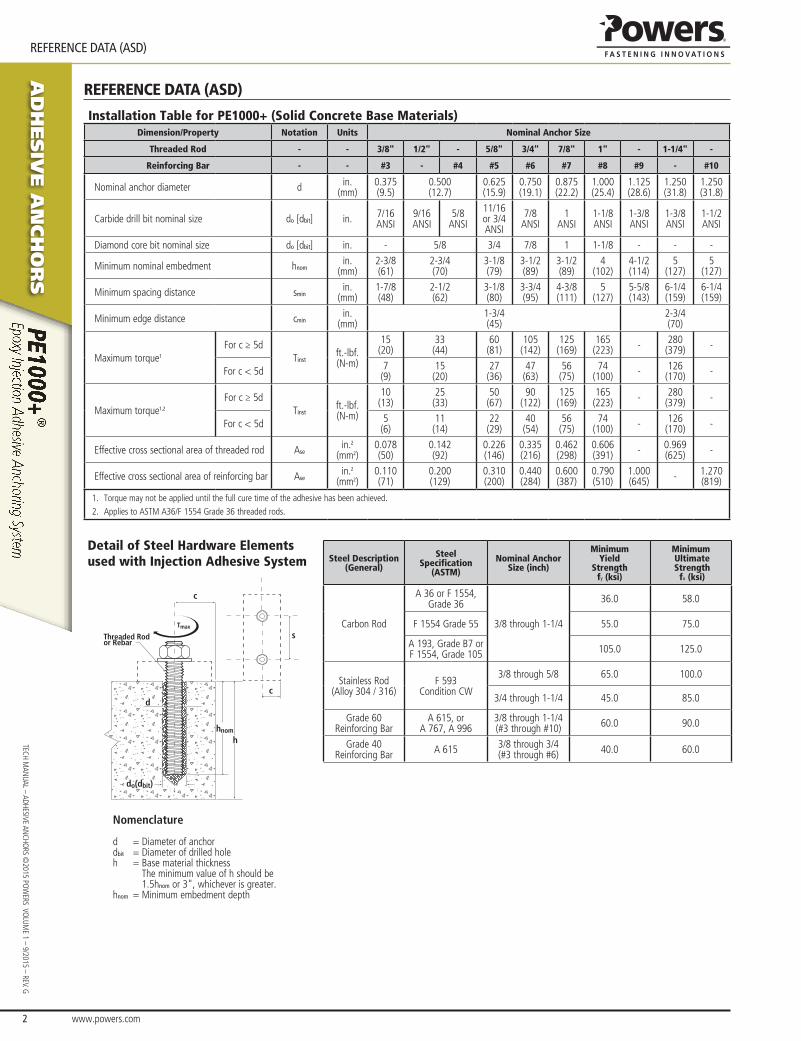
Detail of Steel Hardware Elements used with Injection Adhesive System Steel Description
(General)
Steel Specification
(ASTM)
Nominal Anchor Size (inch)
Minimum Yield
Strength fy (ksi)
Minimum Ultimate Strength
fu (ksi)
Carbon rod
A 36 or F 1554, grade 36
3/8 through 1-1/4
36.0 58.0
F 1554 grade 55 55.0 75.0
A 193, grade B7 or F 1554, grade 105 105.0 125.0
stainless rod (Alloy 304 / 316)
F 593 Condition CW
3/8 through 5/8 65.0 100.0
3/4 through 1-1/4 45.0 85.0
grade 60 reinforcing Bar
A 615, or A 767, A 996
3/8 through 1-1/4 (#3 through #10) 60.0 90.0
grade 40 reinforcing Bar A 615 3/8 through 3/4
(#3 through #6) 40.0 60.0
Tmax
hnom
h
c
c
s
d
do(dbit)
Threaded Rodor Rebar
Nomenclature
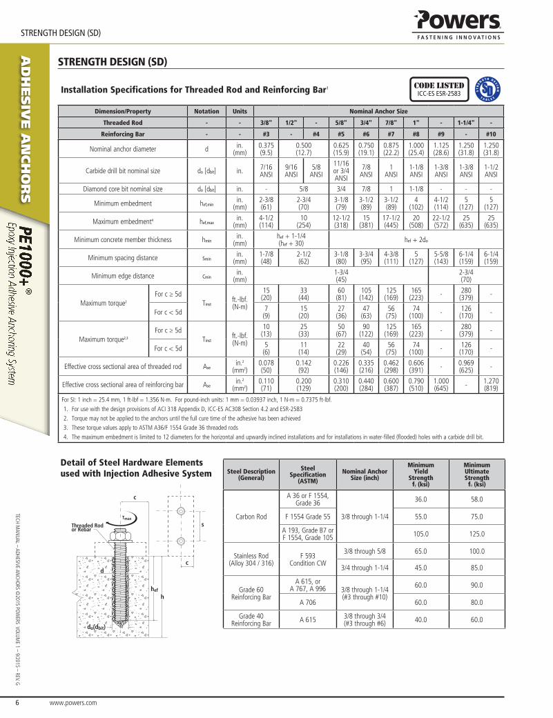
d = diameter of anchordbit = diameter of drilled holeh = Base material thickness
The minimum value of h should be 1.5hnom or 3", whichever is greater.
hnom = Minimum embedment depth
www.powers.com 3
aD
hesiV
e a
nch
or
s
ReFeReNCe DATA (ASD)
TECH
MAN
UAL
– AD
HESI
VE A
NCH
ORS
©20
15 P
OW
ERS
VO
LUM
E 1
– 9/
2015
– R
EV. G
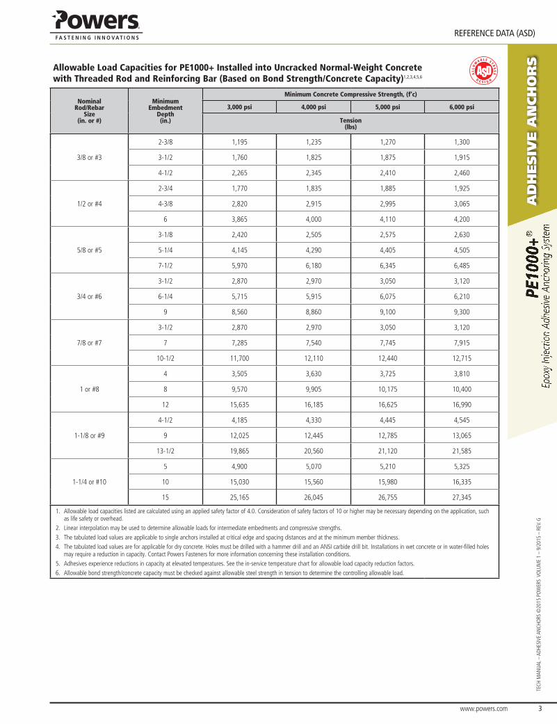
Allowable Load Capacities for PE1000+ Installed into Uncracked Normal-Weight Concrete with Threaded Rod and Reinforcing Bar (Based on Bond Strength/Concrete Capacity)1,2,3,4,5,6
Nominal Rod/Rebar
Size (in. or #)
Minimum Embedment
Depth (in.)
Minimum Concrete Compressive Strength, (f’c)
3,000 psi 4,000 psi 5,000 psi 6,000 psi
Tension (lbs)
3/8 or #3
2-3/8 1,195 1,235 1,270 1,300
3-1/2 1,760 1,825 1,875 1,915
4-1/2 2,265 2,345 2,410 2,460
1/2 or #4
2-3/4 1,770 1,835 1,885 1,925
4-3/8 2,820 2,915 2,995 3,065
6 3,865 4,000 4,110 4,200
5/8 or #5
3-1/8 2,420 2,505 2,575 2,630
5-1/4 4,145 4,290 4,405 4,505
7-1/2 5,970 6,180 6,345 6,485
3/4 or #6
3-1/2 2,870 2,970 3,050 3,120
6-1/4 5,715 5,915 6,075 6,210
9 8,560 8,860 9,100 9,300
7/8 or #7
3-1/2 2,870 2,970 3,050 3,120
7 7,285 7,540 7,745 7,915
10-1/2 11,700 12,110 12,440 12,715
1 or #8
4 3,505 3,630 3,725 3,810
8 9,570 9,905 10,175 10,400
12 15,635 16,185 16,625 16,990
1-1/8 or #9
4-1/2 4,185 4,330 4,445 4,545
9 12,025 12,445 12,785 13,065
13-1/2 19,865 20,560 21,120 21,585
1-1/4 or #10
5 4,900 5,070 5,210 5,325
10 15,030 15,560 15,980 16,335
15 25,165 26,045 26,755 27,345
1. Allowable load capacities listed are calculated using an applied safety factor of 4.0. Consideration of safety factors of 10 or higher may be necessary depending on the application, such as life safety or overhead.
2. Linear interpolation may be used to determine allowable loads for intermediate embedments and compressive strengths.3. The tabulated load values are applicable to single anchors installed at critical edge and spacing distances and at the minimum member thickness.4. The tabulated load values are for applicable for dry concrete. Holes must be drilled with a hammer drill and an ANSI carbide drill bit. Installations in wet concrete or in water-filled holes
may require a reduction in capacity. Contact Powers Fasteners for more information concerning these installation conditions.5. Adhesives experience reductions in capacity at elevated temperatures. See the in-service temperature chart for allowable load capacity reduction factors.6. Allowable bond strength/concrete capacity must be checked against allowable steel strength in tension to determine the controlling allowable load.
aD
hesiV
e a
nch
or
s
www.powers.com 4
TECH MAN
UAL – ADHESIVE ANCHO
RS ©2015 PO
WERS VO
LUME 1 – 9/2015 – REV. G
ReFeReNCe DATA (ASD)
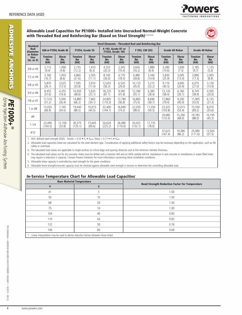
Allowable Load Capacities for PE1000+ Installed into Uncracked Normal-Weight Concrete with Threaded Rod and Reinforcing Bar (Based on Steel Strength)1,2,3,4,5,6
Nominal Rod
Diameter or Rebar
Size(in. or #)
Steel Elements - Threaded Rod and Reinforcing Bar
A36 or F1554, Grade 36 F1554, Grade 55 A 193, Grade B7 or F1554, Grade 105 F 593, CW (SS) Grade 60 Rebar Grade 40 Rebar
Tensionlbs
(kN)
Shearlbs
(kN)
Tensionlbs
(kN)
Shearlbs
(kN)
Tensionlbs
(kN)
Shearlbs
(kN)
Tensionlbs
(kN)
Shearlbs
(kN)
Tensionlbs
(kN)
Shearlbs
(kN)
Tensionlbs
(kN)
Shearlbs
(kN)
3/8 or #3 2,115(9.4)
1,090(4.8)
2,735(12.2)
1,410(6.3)
4,555(20.3)
2,345(10.4)
3,645(16.2)
1,880(8.4)
3,280(14.6)
1,690(7.5)
2,185(9.7)
1,125(5.0)
1/2 or #4 3,760(16.7)
1,935(8.6)
4,860(21.6)
2,505(11.1)
8,100(36.0)
4,170(18.5)
6,480(28.8)
3,340(14.9)
5,830(25.9)
3,005(13.4)
3,890(17.3)
2,005(8.9)
5/8 or #5 5,870(26.1)
3,025(13.5)
7,595(33.8)
3,910(17.4)
12,655(56.3)
6,520(29.0)
10,125(45.0)
5,215(23.2)
9,110(40.5)
4,695(20.9)
6,075(27.0)
3,130(13.9)
3/4 or #6 8,455(37.6)
4,355(19.4)
10,935(48.6)
5,635(25.1)
18,225(81.1)
9,390(41.8)
12,390(55.1)
6,385(28.4)
13,120(58.4)
6,760(30.1)
8,745(38.9)
4,505(20.0)
7/8 or #7 11,510(51.2)
5,930(26.4)
14,885(66.2)
7,665(34.1)
24,805(110.3)
12,780(56.8)
16,865(75.0)
8,690(38.7)
17,860(79.4)
9,200(40.9)
11,905(53.0)
6,135(27.3)
1 or #8 15,035(66.9)
7,745(34.5)
19,440(86.5)
10,015(44.5)
32,400(144.1)
16,690(74.2)
22,030(98.0)
11,350(50.5)
23,325(103.8)
12,015(53.4)
15,550(69.2)
8,010(35.6)
#9 29,680(132.0)
15,290(68.0)
19,785(88.0)
10,195(45.3)
1-1/4 23,490(104.5)
12,100(53.8)
30,375(135.1)
15,645(69.6)
50,620(225.2)
26,080(116.0)
34,425(153.1)
17,735(78.9)
#10 37,625(167.4)
19,380(86.2)
25,080(111.6)
12,920(57.5)
1. AISC defined steel strength (ASD): Tensile = 0.33 • Fu • Anom, Shear = 0.17 • Fu • Anom
2. Allowable load capacities listed are calculated for the steel element type. Consideration of applying additional safety factors may be necessary depending on the application, such as life safety or overhead.
3. The tabulated load values are applicable to single anchors at critical edge and spacing distances and at the minimum member thickness.4. The tabulated load values are for dry concrete. Holes must be drilled with a hammer drill and an ANSI carbide drill bit. Installation in wet concrete or installations in water-filled holes
may require a reduction in capacity. Contact Powers Fasteners for more information concerning these installation conditions.5. Allowable shear capacity is controlled by steel strength for the given conditions.6. Allowable bond strength/concrete capacity must be checked against allowable steel strength in tension to determine the controlling allowable load.
In-Service Temperature Chart for Allowable Load Capacities1
Base Material TemperatureBond Strength Reduction Factor for Temperature
oF oC
41 5 1.00
50 10 1.00
68 20 1.00
75 14 1.00
104 40 0.85
110 43 0.82
122 50 0.76
140 60 0.69
1. Linear interpolation may be used to derive reduction factors between those listed.
www.powers.com 5
aD
hesiV
e a
nch
or
s
ReFeReNCe DATA (ASD)
TECH
MAN
UAL
– AD
HESI
VE A
NCH
ORS
©20
15 P
OW
ERS
VO
LUM
E 1
– 9/
2015
– R
EV. G
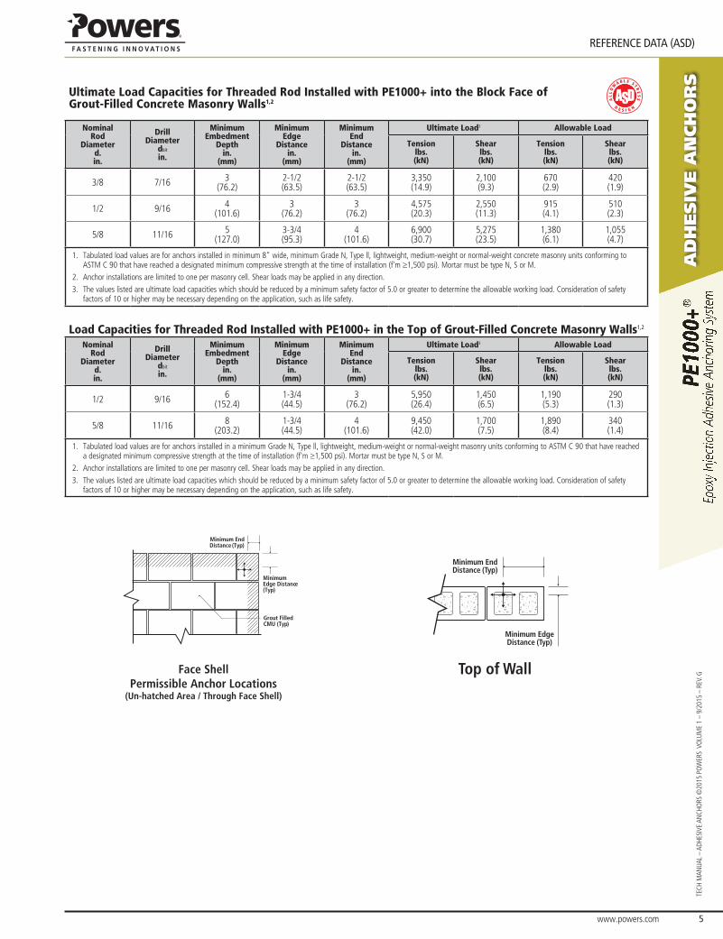
ultimate load capacities for threaded rod Installed with pe1000+ into the block Face of grout-Filled concrete masonry walls1,2
NominalRod
Diameterd.in.
DrillDiameter
dbit
in.
MinimumEmbedment
Depthin.
(mm)
MinimumEdge
Distancein.
(mm)
MinimumEnd
Distancein.
(mm)
Ultimate Load3 Allowable Load
Tensionlbs.(kN)
Shearlbs.(kN)
Tensionlbs.(kN)
Shearlbs.(kN)
3/8 7/16 3(76.2)
2-1/2(63.5)
2-1/2(63.5)
3,350(14.9)
2,100(9.3)
670(2.9)
420(1.9)
1/2 9/16 4(101.6)
3(76.2)
3(76.2)
4,575(20.3)
2,550 (11.3)
915(4.1)
510(2.3)
5/8 11/16 5(127.0)
3-3/4(95.3)
4(101.6)
6,900(30.7)
5,275 (23.5)
1,380(6.1)
1,055(4.7)
1. Tabulated load values are for anchors installed in minimum 8" wide, minimum Grade N, Type ll, lightweight, medium-weight or normal-weight concrete masonry units conforming to ASTM C 90 that have reached a designated minimum compressive strength at the time of installation (f'm ≥1,500 psi). Mortar must be type N, S or M.
2. Anchor installations are limited to one per masonry cell. Shear loads may be applied in any direction.3. The values listed are ultimate load capacities which should be reduced by a minimum safety factor of 5.0 or greater to determine the allowable working load. Consideration of safety
factors of 10 or higher may be necessary depending on the application, such as life safety.
Load Capacities for Threaded Rod Installed with PE1000+ in the Top of Grout-Filled Concrete Masonry Walls1,2
NominalRod
Diameterd.in.
DrillDiameter
dbit
in.
MinimumEmbedment
Depthin.
(mm)
MinimumEdge
Distancein.
(mm)
MinimumEnd
Distancein.
(mm)
Ultimate Load3 Allowable Load
Tensionlbs.(kN)
Shearlbs.(kN)
Tensionlbs.(kN)
Shearlbs.(kN)
1/2 9/16 6(152.4)
1-3/4(44.5)
3(76.2)
5,950(26.4)
1,450(6.5)
1,190(5.3)
290(1.3)
5/8 11/16 8(203.2)
1-3/4(44.5)
4(101.6)
9,450(42.0)
1,700(7.5)
1,890(8.4)
340(1.4)
1. Tabulated load values are for anchors installed in a minimum Grade N, Type ll, lightweight, medium-weight or normal-weight masonry units conforming to ASTM C 90 that have reached a designated minimum compressive strength at the time of installation (f'm ≥1,500 psi). Mortar must be type N, S or M.
2. Anchor installations are limited to one per masonry cell. Shear loads may be applied in any direction.3. The values listed are ultimate load capacities which should be reduced by a minimum safety factor of 5.0 or greater to determine the allowable working load. Consideration of safety
factors of 10 or higher may be necessary depending on the application, such as life safety.
Minimum End Distance (Typ)
Minimum Edge Distance (Typ)
Face Shell Permissible Anchor Locations
(Un-hatched Area / Through Face Shell)
Grout Filled CMU (Typ)
Top of Wall
Minimum End Distance (Typ)
Minimum Edge Distance (Typ)
aD
hesiV
e a
nch
or
s
www.powers.com 6
TECH MAN
UAL – ADHESIVE ANCHO
RS ©2015 PO
WERS VO
LUME 1 – 9/2015 – REV. G
STReNGTH DeSIGN (SD)
strength desIgn (sd)
Installation Specifications for Threaded Rod and Reinforcing Bar1 Code listedICC-eS eSR-2583
Dimension/Property Notation Units Nominal Anchor Size
Threaded Rod - - 3/8" 1/2" - 5/8" 3/4" 7/8" 1" - 1-1/4" -
Reinforcing Bar - - #3 - #4 #5 #6 #7 #8 #9 - #10
Nominal anchor diameter d in. (mm)
0.375 (9.5)
0.500 (12.7)
0.625 (15.9)
0.750 (19.1)
0.875 (22.2)
1.000 (25.4)
1.125 (28.6)
1.250 (31.8)
1.250 (31.8)
Carbide drill bit nominal size do [dbit] in. 7/16 ANSI
9/16 ANSI
5/8 ANSI
11/16 or 3/4 ANSI
7/8 ANSI
1 ANSI
1-1/8 ANSI
1-3/8 ANSI
1-3/8 ANSI
1-1/2 ANSI
Diamond core bit nominal size do [dbit] in. - 5/8 3/4 7/8 1 1-1/8 - - -
Minimum embedment hef,minin.
(mm)2-3/8 (61)
2-3/4 (70)
3-1/8 (79)
3-1/2 (89)
3-1/2 (89)
4 (102)
4-1/2 (114)
5 (127)
5 (127)
Maximum embedment4 hef,maxin.
(mm)4-1/2 (114)
10(254)
12-1/2(318)
15(381)
17-1/2(445)
20(508)
22-1/2(572)
25(635)
25(635)
Minimum concrete member thickness hminin.
(mm)hef + 1-1/4 (hef + 30) hef + 2do
Minimum spacing distance sminin.
(mm)1-7/8 (48)
2-1/2 (62)
3-1/8 (80)
3-3/4 (95)
4-3/8 (111)
5 (127)
5-5/8 (143)
6-1/4 (159)
6-1/4 (159)
Minimum edge distance cminin.
(mm)1-3/4 (45)
2-3/4 (70)
Maximum torque2
For c ≥ 5dTinst
ft.-lbf. (N-m)
15 (20)
33 (44)
60 (81)
105 (142)
125 (169)
165 (223) - 280
(379) -
For c < 5d 7 (9)
15 (20)
27 (36)
47 (63)
56 (75)
74 (100) - 126
(170) -
Maximum torque2,3
For c ≥ 5dTinst
ft.-lbf. (N-m)
10 (13)
25 (33)
50 (67)
90 (122)
125 (169)
165 (223) - 280
(379) -
For c < 5d 5 (6)
11 (14)
22 (29)
40 (54)
56 (75)
74 (100) - 126
(170) -
Effective cross sectional area of threaded rod Asein.2
(mm2)0.078 (50)
0.142 (92)
0.226 (146)
0.335 (216)
0.462 (298)
0.606 (391) - 0.969
(625) -
Effective cross sectional area of reinforcing bar Asein.2
(mm2)0.110 (71)
0.200 (129)
0.310 (200)
0.440 (284)
0.600 (387)
0.790 (510)
1.000 (645) - 1.270
(819)
For SI: 1 inch = 25.4 mm, 1 ft-lbf = 1.356 N-m. For pound-inch units: 1 mm = 0.03937 inch, 1 N-m = 0.7375 ft-lbf.1. For use with the design provisions of ACI 318 Appendix D, ICC-ES AC308 Section 4.2 and ESR-25832. Torque may not be applied to the anchors until the full cure time of the adhesive has been achieved3. These torque values apply to ASTM A36/F 1554 Grade 36 threaded rods4. The maximum embedment is limited to 12 diameters for the horizontal and upwardly inclined installations and for installations in water-filled (flooded) holes with a carbide drill bit.
Detail of Steel Hardware Elements used with Injection Adhesive System Steel Description
(General)
Steel Specification
(ASTM)
Nominal Anchor Size (inch)
Minimum Yield
Strength fy (ksi)
Minimum Ultimate Strength
fu (ksi)
Carbon Rod
A 36 or F 1554, Grade 36
3/8 through 1-1/4
36.0 58.0
F 1554 Grade 55 55.0 75.0
A 193, Grade B7 or F 1554, Grade 105 105.0 125.0
Stainless Rod (Alloy 304 / 316)
F 593 Condition CW
3/8 through 5/8 65.0 100.0
3/4 through 1-1/4 45.0 85.0
Grade 60 Reinforcing Bar
A 615, or A 767, A 996 3/8 through 1-1/4
(#3 through #10)
60.0 90.0
A 706 60.0 80.0
Grade 40 Reinforcing Bar A 615 3/8 through 3/4
(#3 through #6) 40.0 60.0
Tmax
hef
h
c
c
s
d
do(dbit)
Threaded Rodor Rebar
www.powers.com 7
aD
hesiV
e a
nch
or
s
STReNGTH DeSIGN (SD)
TECH
MAN
UAL
– AD
HESI
VE A
NCH
ORS
©20
15 P
OW
ERS
VO
LUM
E 1
– 9/
2015
– R
EV. G
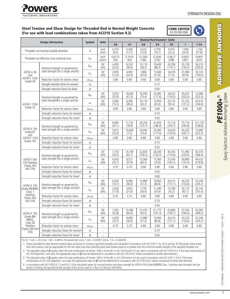
Steel Tension and Shear Design for Threaded Rod in Normal Weight Concrete(For use with load combinations taken from ACI318 Section 9.2)
Code listedICC-eS eSR-2583
Design Information Symbol UnitsNominal Rod Diameter1 (inch)
3/8 1/2 5/8 3/4 7/8 1 1-1/4
Threaded rod nominal outside diameter d inch(mm)
0.375(9.5)
0.500(12.7)
0.625(15.9)
0.750(19.1)
0.875(22.2)
1.000(25.4)
1.250(31.8)
Threaded rod effective cross-sectional area Aseinch2
(mm2)0.0775
(50)0.1419
(92)0.2260(146)
0.3345(216)
0.4617(298)
0.6057(391)
0.9691(625)
ASTM A 36 and
ASTM F 1554 Grade 36
Nominal strength as governed by steel strength (for a single anchor)
Nsalbf
(kN)4,495(20.0)
8,230(36.6)
13,110(58.3)
19,400(86.3)
26,780(119.1)
35,130(156.3)
56,210(250.0)
Vsalbf
(kN)2,695(12.0)
4,940(22.0)
7,860(35.0)
11,640(51.8)
16,070(71.4)
21,080(93.8)
33,725(150.0)
Reduction factor for seismic shear aV,seis - 0.80 0.80 0.80 0.80 0.80 0.80 0.80
Strength reduction factor for tension2 f - 0.75
Strength reduction factor for shear2 f - 0.65
ASTM F 1554 Grade 55
Nominal strength as governed by steel strength(for a single anchor)
Nsalbf
(kN)5,810(25.9)
10,640(47.3)
16,950(75.4)
25,085(111.6)
34,625(154.0)
45,425(202.0)
72,680(323.3)
Vsalbf
(kN)3,485(15.5)
6,385(28.4)
10,170(45.2)
15,050(67.0)
20,775(92.4)
27,255(121.2)
43,610(194.0)
Reduction factor for seismic shear aV,seis - 0.80 0.80 0.80 0.80 0.80 0.80 0.80
Strength reduction factor for tension2 f - 0.75
Strength reduction factor for shear2 f - 0.65
ASTM A 193Grade B7
and ASTM F 1554
Grade 105
Nominal strength as governed by steel strength (for a single anchor)
Nsalbf
(kN)9,685(43.1)
17,735(78.9)
28,250(125.7)
41,810(186.0)
57,710(256.7)
75,710(336.8)
121,135(538.8)
Vsalbf
(kN)5,815(25.9)
10,640(7.3)
16,950(75.4)
25,085(111.6)
34,625(154.0)
45,425(202.1)
72,680(323.3)
Reduction factor for seismic shear aV,seis - 0.80 0.80 0.80 0.80 0.80 0.80 0.80
Strength reduction factor for tension2 f - 0.75
Strength reduction factor for shear2 f - 0.65
ASTM F 593CW Stainless(Types 304 and 316)
Nominal strength as governed by steel strength (for a single anchor)
Nsalbf
(kN)7,750(34.5)
14,190(63.1)
22,600(100.5)
28,430(126.5)
39,245(174.6)
51,485(229.0)
82,370(366.4)
Vsalbf
(kN)4,650(20.7)
8,515(37.9)
13,560(60.3)
17,060(75.9)
23,545(104.7)
30,890(137.4)
49,425(219.8)
Reduction factor for seismic shear aV,seis - 0.70 0.70 0.80 0.80 0.80 0.80 0.80
Strength reduction factor for tension3 f - 0.65
Strength reduction factor for shear3 f - 0.60
ASTM A 193Grade B8/B8M,
Class 1 Stainless
(Types 304and 316)
Nominal strength as governed by steel strength (for a single anchor)4
Nsalbf
(kN)4,420(19.7)
8,090(36.0)
12,880(57.3)
19,065(84.8)
26,315(117.1)
34,525(153.6)
55,240(245.7)
Vsalbf
(kN)2,650(11.8)
4,855(21.6)
7,730(34.4)
11,440(50.9)
15,790(70.2)
20,715(92.1)
33,145(147.4)
Reduction factor for seismic shear aV,seis - 0.70 0.70 0.80 0.80 0.80 0.80 0.80
Strength reduction factor for tension2 f - 0.75
Strength reduction factor for shear2 f - 0.65
ASTM A 193Grade B8/
B8M2,Class 2B Stainless
(Types 304 and 316)
Nominal strength as governed by steel strength (for a single anchor)
Nsalbf
(kN)7,365(32.8)
13,480(60.0)
21,470(95.5)
31,775(141.3)
43,860(195.1)
57,545(256.0)
92,065(409.5)
Vsalbf
(kN)4,420(19.7)
8,085(36.0)
12,880(57.3)
19,065(84.8)
26,315(117.1)
34,525(153.6)
55,240(245.7)
Reduction factor for seismic shear aV,seis - 0.70 0.70 0.80 0.80 0.80 0.80 0.80
Strength reduction factor for tension2 f - 0.75
Strength reduction factor for shear2 f - 0.65
For SI: 1 inch = 25.4 mm, 1 lbf = 4.448 N. For pound-inch units: 1 mm = 0.03937 inches, 1 N = 0.2248 lbf.1. Values provided for steel element material types are based on minimum specified strengths and calculated in accordance with ACI 318-11 Eq. (D-2) and Eq. (D-29) except where noted.
Nuts and washers must be appropriate for the rod. Nuts must have specified proof load stresses equal to or greater than the minimum tensile strength of the specified threaded rod.2. The tabulated value of f applies when the load combinations of Section 1605.2 of the IBC or ACI 318 Section 9.2 are used in accordance with ACI 318 D.4.3. If the load combinations of
ACI 318 Appendix C are used, the appropriate value of f must be determined in accordance with ACI 318 D.4.4. Values correspond to ductile steel elements.3. The tabulated value of f applies when the load combinations of Section 1605.2 of the IBC or ACI 318 Section 9.2 are used in accordance with ACI 318-11 D.4.3. If the load
combinations of ACI 318 Appendix C are used, the appropriate value of f must be determined in accordance with ACI 318 D.4.4. Values correspond to brittle steel elements4. In accordance with ACI 318 D.5.1.2 and D.6.1.2 the calculated values for nominal tension and shear strength for ASTM A193 Grade B8/B8M Class 1 stainless steel threaded rods are
based on limiting the specified tensile strength of the anchor steel to 1.9fy or 57,000 psi (393 MPa).
aD
hesiV
e a
nch
or
s
www.powers.com 8
TECH MAN
UAL – ADHESIVE ANCHO
RS ©2015 PO
WERS VO
LUME 1 – 9/2015 – REV. G
STReNGTH DeSIGN (SD)
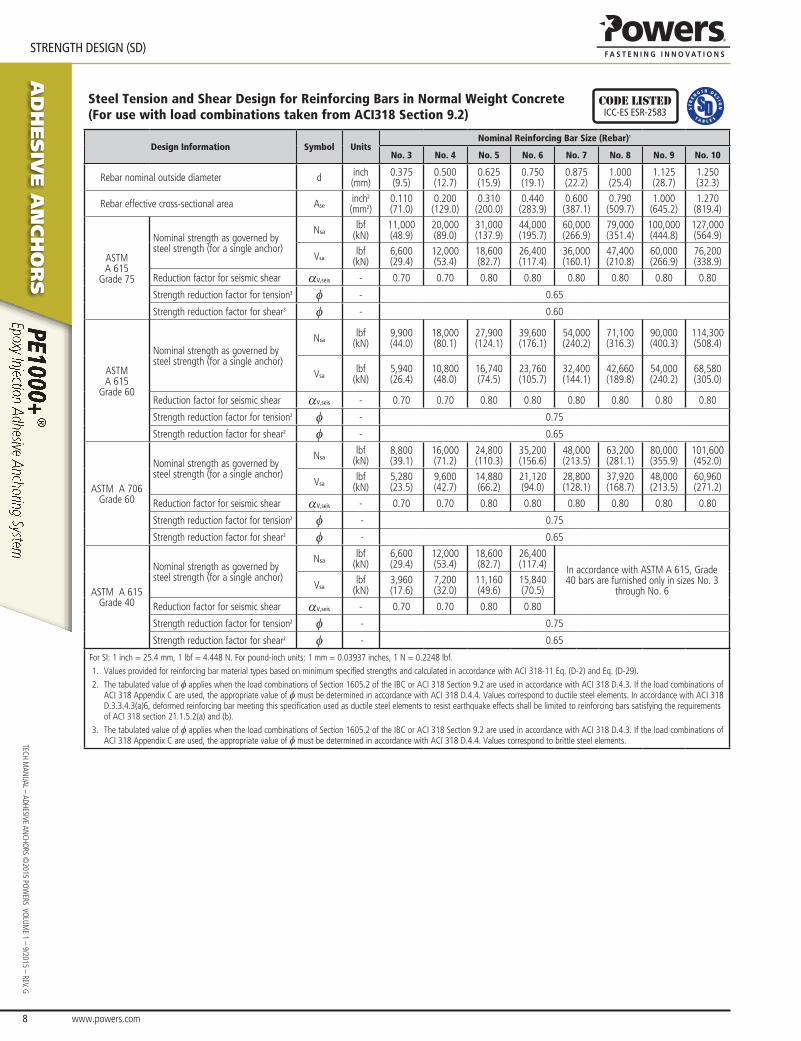
Steel Tension and Shear Design for Reinforcing Bars in Normal Weight Concrete(For use with load combinations taken from ACI318 Section 9.2)
Code listedICC-eS eSR-2583
Design Information Symbol UnitsNominal Reinforcing Bar Size (Rebar)1
No. 3 No. 4 No. 5 No. 6 No. 7 No. 8 No. 9 No. 10
Rebar nominal outside diameter d inch(mm)
0.375(9.5)
0.500(12.7)
0.625(15.9)
0.750(19.1)
0.875(22.2)
1.000(25.4)
1.125(28.7)
1.250(32.3)
Rebar effective cross-sectional area Aseinch2
(mm2)0.110(71.0)
0.200(129.0)
0.310(200.0)
0.440(283.9)
0.600(387.1)
0.790(509.7)
1.000(645.2)
1.270(819.4)
ASTMA 615
Grade 75
Nominal strength as governed by steel strength (for a single anchor)
Nsalbf
(kN)11,000(48.9)
20,000(89.0)
31,000(137.9)
44,000(195.7)
60,000(266.9)
79,000(351.4)
100,000(444.8)
127,000(564.9)
Vsalbf
(kN)6,600(29.4)
12,000(53.4)
18,600(82.7)
26,400(117.4)
36,000(160.1)
47,400(210.8)
60,000(266.9)
76,200(338.9)
Reduction factor for seismic shear aV,seis - 0.70 0.70 0.80 0.80 0.80 0.80 0.80 0.80
Strength reduction factor for tension3 f - 0.65
Strength reduction factor for shear3 f - 0.60
ASTMA 615
Grade 60
Nominal strength as governed by steel strength (for a single anchor)
Nsalbf
(kN)9,900(44.0)
18,000(80.1)
27,900(124.1)
39,600(176.1)
54,000(240.2)
71,100(316.3)
90,000(400.3)
114,300(508.4)
Vsalbf
(kN)5,940(26.4)
10,800(48.0)
16,740(74.5)
23,760(105.7)
32,400(144.1)
42,660(189.8)
54,000(240.2)
68,580(305.0)
Reduction factor for seismic shear aV,seis - 0.70 0.70 0.80 0.80 0.80 0.80 0.80 0.80
Strength reduction factor for tension2 f - 0.75
Strength reduction factor for shear2 f - 0.65
ASTM A 706 Grade 60
Nominal strength as governed by steel strength (for a single anchor)
Nsalbf
(kN)8,800(39.1)
16,000(71.2)
24,800(110.3)
35,200(156.6)
48,000(213.5)
63,200(281.1)
80,000(355.9)
101,600(452.0)
Vsalbf
(kN)5,280(23.5)
9,600(42.7)
14,880(66.2)
21,120(94.0)
28,800(128.1)
37,920(168.7)
48,000(213.5)
60,960(271.2)
Reduction factor for seismic shear aV,seis - 0.70 0.70 0.80 0.80 0.80 0.80 0.80 0.80
Strength reduction factor for tension2 f - 0.75
Strength reduction factor for shear2 f - 0.65
ASTM A 615 Grade 40
Nominal strength as governed by steel strength (for a single anchor)
Nsalbf
(kN)6,600(29.4)
12,000(53.4)
18,600(82.7)
26,400(117.4) In accordance with ASTM A 615, Grade
40 bars are furnished only in sizes No. 3 through No. 6Vsa
lbf(kN)
3,960(17.6)
7,200(32.0)
11,160(49.6)
15,840(70.5)
Reduction factor for seismic shear aV,seis - 0.70 0.70 0.80 0.80
Strength reduction factor for tension2 f - 0.75
Strength reduction factor for shear2 f - 0.65
For SI: 1 inch = 25.4 mm, 1 lbf = 4.448 N. For pound-inch units: 1 mm = 0.03937 inches, 1 N = 0.2248 lbf.1. Values provided for reinforcing bar material types based on minimum specified strengths and calculated in accordance with ACI 318-11 Eq. (D-2) and Eq. (D-29).2. The tabulated value of f applies when the load combinations of Section 1605.2 of the IBC or ACI 318 Section 9.2 are used in accordance with ACI 318 D.4.3. If the load combinations of
ACI 318 Appendix C are used, the appropriate value of f must be determined in accordance with ACI 318 D.4.4. Values correspond to ductile steel elements. In accordance with ACI 318 D.3.3.4.3(a)6, deformed reinforcing bar meeting this specification used as ductile steel elements to resist earthquake effects shall be limited to reinforcing bars satisfying the requirements of ACI 318 section 21.1.5.2(a) and (b).
3. The tabulated value of f applies when the load combinations of Section 1605.2 of the IBC or ACI 318 Section 9.2 are used in accordance with ACI 318 D.4.3. If the load combinations of ACI 318 Appendix C are used, the appropriate value of f must be determined in accordance with ACI 318 D.4.4. Values correspond to brittle steel elements.
www.powers.com 9
aD
hesiV
e a
nch
or
s
STReNGTH DeSIGN (SD)
TECH
MAN
UAL
– AD
HESI
VE A
NCH
ORS
©20
15 P
OW
ERS
VO
LUM
E 1
– 9/
2015
– R
EV. G
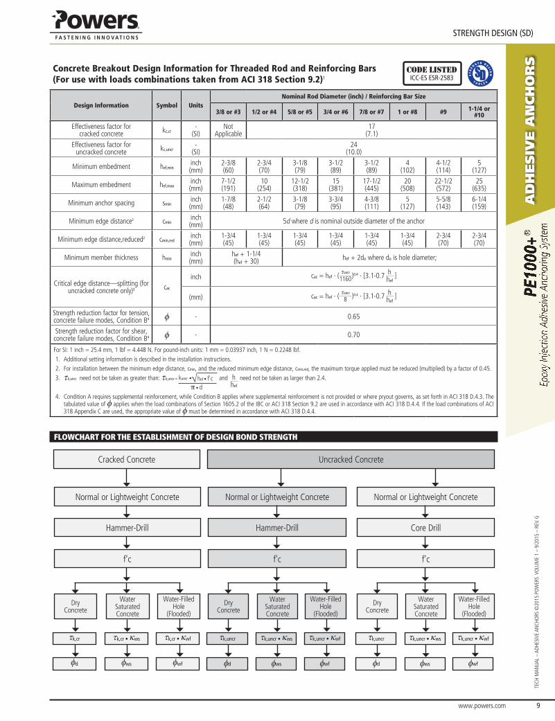
Concrete Breakout Design Information for Threaded Rod and Reinforcing Bars (For use with loads combinations taken from ACI 318 Section 9.2)1
Code listedICC-eS eSR-2583
Design Information Symbol UnitsNominal Rod Diameter (inch) / Reinforcing Bar Size
3/8 or #3 1/2 or #4 5/8 or #5 3/4 or #6 7/8 or #7 1 or #8 #9 1-1/4 or #10
Effectiveness factor for cracked concrete kc,cr
-(SI)
Not Applicable
17(7.1)
Effectiveness factor for uncracked concrete kc,uncr
-(SI)
24(10.0)
Minimum embedment hef,mininch(mm)
2-3/8(60)
2-3/4(70)
3-1/8(79)
3-1/2(89)
3-1/2(89)
4(102)
4-1/2(114)
5(127)
Maximum embedment hef,maxinch(mm)
7-1/2(191)
10(254)
12-1/2(318)
15(381)
17-1/2(445)
20(508)
22-1/2(572)
25(635)
Minimum anchor spacing smininch(mm)
1-7/8(48)
2-1/2(64)
3-1/8(79)
3-3/4(95)
4-3/8(111)
5(127)
5-5/8(143)
6-1/4(159)
Minimum edge distance2 cmininch(mm) 5d where d is nominal outside diameter of the anchor
Minimum edge distance,reduced2 cmin,redinch(mm)
1-3/4(45)
1-3/4(45)
1-3/4(45)
1-3/4(45)
1-3/4(45)
1-3/4(45)
2-3/4(70)
2-3/4(70)
Minimum member thickness hmininch(mm)
hef + 1-1/4(hef + 30) hef + 2do where do is hole diameter;
Critical edge distance—splitting (for uncracked concrete only)3 cac
inch cac = hef ∙ (tuncr
1160)0.4 ∙ [3.1-0.7 hhef
]
(mm) cac = hef ∙ (tuncr
8 )0.4 ∙ [3.1-0.7 hhef
]
Strength reduction factor for tension, concrete failure modes, Condition B4 f - 0.65
Strength reduction factor for shear, concrete failure modes, Condition B4 f - 0.70
For SI: 1 inch = 25.4 mm, 1 lbf = 4.448 N. For pound-inch units: 1 mm = 0.03937 inch, 1 N = 0.2248 lbf.1. Additional setting information is described in the installation instructions.2. For installation between the minimum edge distance, cmin, and the reduced minimum edge distance, cmin,red, the maximum torque applied must be reduced (multiplied) by a factor of 0.45.3. tk,uncr need not be taken as greater than: tk,uncr = √ hef • f'ckuncr •
π • d
and hhef
need not be taken as larger than 2.4.
4. Condition A requires supplemental reinforcement, while Condition B applies where supplemental reinforcement is not provided or where pryout governs, as set forth in ACI 318 D.4.3. The tabulated value of f applies when the load combinations of Section 1605.2 of the IBC or ACI 318 Section 9.2 are used in accordance with ACI 318 D.4.4. If the load combinations of ACI 318 Appendix C are used, the appropriate value of f must be determined in accordance with ACI 318 D.4.4.
fLoWCHArT for THE ESTABLISHMEnT of DESIGn BonD STrEnGTH
Cracked Concrete
Normal or Lightweight Concrete
Dry Concrete
Water Saturated Concrete
Water-Filled Hole
(Flooded)
Hammer-Drill
f’c
tk,cr tk,cr • κws tk,cr • κwf
fd fws fwf
Uncracked Concrete
Normal or Lightweight Concrete
Dry Concrete
Water Saturated Concrete
Water-Filled Hole
(Flooded)
Hammer-Drill
f’c
tk,uncr tk,uncr • κws tk,uncr • κwf
fd fws fwf
Normal or Lightweight Concrete
Dry Concrete
Water Saturated Concrete
Water-Filled Hole
(Flooded)
Core Drill
f’c
tk,uncr tk,uncr • κws tk,uncr • κwf
fd fws fwf
aD
hesiV
e a
nch
or
s
www.powers.com 10
TECH MAN
UAL – ADHESIVE ANCHO
RS ©2015 PO
WERS VO
LUME 1 – 9/2015 – REV. G
STReNGTH DeSIGN (SD)
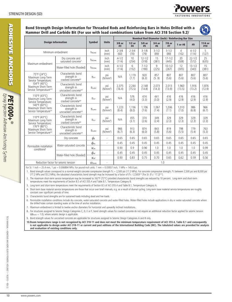
Bond Strength Design Information for Threaded Rods and Reinforcing Bars in Holes Drilled with a Hammer Drill and Carbide Bit (For use with load combinations taken from ACI 318 Section 9.2)1
Design Information Symbol UnitsNominal Rod Diameter (inch) / Reinforcing Bar Size
3/8 or #3
1/2 or #4
5/8 or #5
3/4 or #6
7/8 or #7 1 or #8 #9 11/4 or
#10
Minimum embedment hef,mininch(mm)
2-3/8(60)
2-3/4(70)
3-1/8(79)
3-1/2(89)
3-1/2(89)
4(102
4-1/2(114)
5 (127)
Maximum embedment
Dry concrete and saturated concrete7 hef,max
inch(mm)
4-1/2(114)
10(254)
12-1/2(318)
15(381)
17-1/2(445)
20(508)
22-1/2(572)
25 (635)
Water-filled hole (flooded) hef,maxinch(mm)
4-1/2(114)
6(152)
7-1/2(190)
9(225)
10-1/2(267)
12(305)
13-1/2(343)
15 (381)
75°F (24°C) Maximum Long-Term Service Temperature;
104°F (40°C)Maximum Short-Term Service Temperature4,10
Characteristic bond strength in
cracked concrete5,8tk,cr
psi(N/mm2) N/A 1,119
(7.7)920(6.3)
857(5 .9)
807(5.6)
807(5.6)
807(5.6)
807(5.6)
Characteristic bond strength in
uncracked concrete5,9tk,uncr
psi(N/mm2)
2,375(16.4)
2,244(15.5)
2,148(14.8)
2,073(14.3)
2,013(13.9)
1,960(13.5)
1,916(13.2)
1,876(12.9)
110°F (43°C)Maximum Long-Term Service Temperature;
140°F (60°C) Maximum Short-Term Service Temperature2,4
Characteristic bond strength in
cracked concrete5,8tk,cr
psi(N/mm2) N/A 576
(4.0)474(3.3)
441(3.0)
416(2.9)
416(2.9)
416(2.9)
416(2.9)
Characteristic bond strength in
uncracked concrete5,9tk,uncr
psi(N/mm2)
1,223(8.4)
1,156(8.0)
1,106(7.6)
1,067(7.4)
1,036(7.1)
1,010(7.0)
986(6.8)
966(6.7)
110°F (43°C) Maximum Long-Term Service Temperature;
176°F (80°C) Maximum Short-Term Service Temperature3,4
Characteristic bond strength in
cracked concrete5,8tk,cr
psi(N/mm2) N/A 455
(3.1)374(2.6)
349(2.4)
329(2.3)
329(2.3)
329(2.3)
329(2.3)
Characteristic bond strength in
uncracked concrete5,9tk,uncr
psi(N/mm2)
966(6.7)
913(6.3)
874(6.0)
843(5.8)
819(5.6)
798(5.5)
779(5.4)
763(5.3)
Permissible installation conditions6
Dry concrete fd - 0.65 0.65 0.65 0.65 0.65 0.65 0.65 0.65
Water-saturated concretefws - 0.45 0.45 0.45 0.45 0.45 0.45 0.45 0.45
κws 0.93 0.9 0.96 1.0 1.0 1.0 1.0 0.99
Water-filled hole (flooded)fwf - 0.45 0.45 0.45 0.45 0.45 0.45 0.45 0.45
κwf 0.93 0.83 0.75 0.70 0.65 0.62 0.59 0.56
Reduction factor for seismic tension aN,seis - 1.0
For SI: 1 inch = 25.4 mm, 1 psi = 0.006894 MPa. For pound-inch units: 1 mm = 0.03937 inch, 1 MPa = 145.0 psi.1. Bond strength values correspond to a normal-weight concrete compressive strength f'c = 2,500 psi (17.2 MPa). For concrete compressive strength, f'c between 2,500 psi and 8,000 psi
(17.2 MPa and 55.2 MPa), the tabulated characteristic bond strength may be increased by a factor of (f'c / 2,500)0.12 [For SI: (f'c / 17.2)0.12]. 2. The maximum short-term service temperature may be increased to 162°F (72°C) provided characteristic bond strengths are reduced by 10 percent. Long-term and short-term
temperatures meet the requirements of Section 8.5 of ACI 355.4 and Table 8.1, Temperature Category B.3. Long-term and short-term temperatures meet the requirements of Section 8.5 of ACI 355.4 and Table 8.1, Temperature Category A.4. Short-term base material service temperatures are those that occur over brief intervals, e.g. as a result of diurnal cycling. Long-term base material service temperatures are roughly
constant over significant periods of time.5. Characteristic bond strengths are for sustained loads including dead and live loads.6. Permissible installation conditions include dry concrete, water-saturated concrete and water-filled holes. Water-filled holes include applications in dry or water-saturated concrete where
the drilled holes contain standing water at the time of anchor installation.7. Maximum embedment is limited to twelve anchor diameters for horizontal and upwardly inclined installations. 8. For structures assigned to Seismic Design Categories C, D, E or F, bond strength values for cracked concrete do not require an additional reduction factor applied for seismic tension
(aN,seis = 1.0), where seismic design is applicable. 9. Bond strength values for uncracked concrete are applicable for structures assigned to Seismic Design Categories A and B only.10. Room temperature range is not recognized by ACI 318-11 and does not meet the minimum temperature requirement of ACI 355.4, Table 8.1 and consequently
is not applicable to design under ACI 318-11 or current and past editions of the International Building Code (IBC). The tabulated values are provided for analysis and evaluation of existing conditions only.
www.powers.com 11
aD
hesiV
e a
nch
or
s
STReNGTH DeSIGN (SD)
TECH
MAN
UAL
– AD
HESI
VE A
NCH
ORS
©20
15 P
OW
ERS
VO
LUM
E 1
– 9/
2015
– R
EV. G
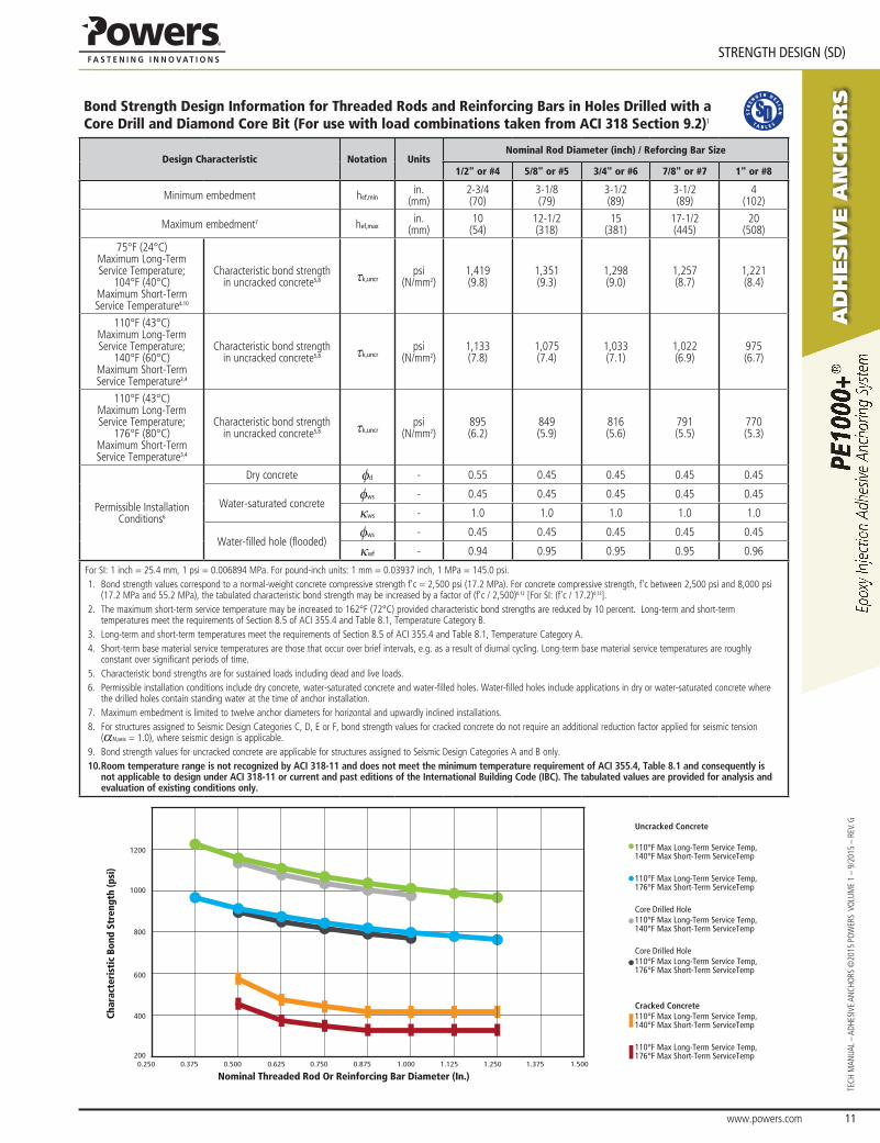
Bond Strength Design Information for Threaded Rods and Reinforcing Bars in Holes Drilled with a Core Drill and Diamond Core Bit (For use with load combinations taken from ACI 318 Section 9.2)1
Design Characteristic Notation UnitsNominal Rod Diameter (inch) / Reforcing Bar Size
1/2" or #4 5/8" or #5 3/4" or #6 7/8" or #7 1" or #8
Minimum embedment hef,minin.
(mm)2-3/4 (70)
3-1/8 (79)
3-1/2 (89)
3-1/2 (89)
4 (102)
Maximum embedment7 hef,maxin.
(mm)10
(54)12-1/2(318)
15(381)
17-1/2(445)
20(508)
75°F (24°C) Maximum Long-Term Service Temperature;
104°F (40°C) Maximum Short-Term Service Temperature4,10
Characteristic bond strength in uncracked concrete5,8 tk,uncr
psi (N/mm2)
1,419 (9.8)
1,351 (9.3)
1,298 (9.0)
1,257 (8.7)
1,221 (8.4)
110°F (43°C) Maximum Long-Term Service Temperature;
140°F (60°C) Maximum Short-Term Service Temperature2,4
Characteristic bond strength in uncracked concrete5,8 tk,uncr
psi (N/mm2)
1,133 (7.8)
1,075 (7.4)
1,033(7.1)
1,022(6.9)
975(6.7)
110°F (43°C) Maximum Long-Term Service Temperature;
176°F (80°C) Maximum Short-Term Service Temperature3,4
Characteristic bond strength in uncracked concrete5,8 tk,uncr
psi (N/mm2)
895(6.2)
849(5.9)
816(5.6)
791(5.5)
770(5.3)
Permissible Installation Conditions6
Dry concrete fd - 0.55 0.45 0.45 0.45 0.45
Water-saturated concretefws - 0.45 0.45 0.45 0.45 0.45
κws - 1.0 1.0 1.0 1.0 1.0
Water-filled hole (flooded)fws - 0.45 0.45 0.45 0.45 0.45
κwf - 0.94 0.95 0.95 0.95 0.96
For SI: 1 inch = 25.4 mm, 1 psi = 0.006894 MPa. For pound-inch units: 1 mm = 0.03937 inch, 1 MPa = 145.0 psi.1. Bond strength values correspond to a normal-weight concrete compressive strength f'c = 2,500 psi (17.2 MPa). For concrete compressive strength, f'c between 2,500 psi and 8,000 psi
(17.2 MPa and 55.2 MPa), the tabulated characteristic bond strength may be increased by a factor of (f'c / 2,500)0.12 [For SI: (f'c / 17.2)0.12]. 2. The maximum short-term service temperature may be increased to 162°F (72°C) provided characteristic bond strengths are reduced by 10 percent. Long-term and short-term
temperatures meet the requirements of Section 8.5 of ACI 355.4 and Table 8.1, Temperature Category B.3. Long-term and short-term temperatures meet the requirements of Section 8.5 of ACI 355.4 and Table 8.1, Temperature Category A.4. Short-term base material service temperatures are those that occur over brief intervals, e.g. as a result of diurnal cycling. Long-term base material service temperatures are roughly
constant over significant periods of time.5. Characteristic bond strengths are for sustained loads including dead and live loads.6. Permissible installation conditions include dry concrete, water-saturated concrete and water-filled holes. Water-filled holes include applications in dry or water-saturated concrete where
the drilled holes contain standing water at the time of anchor installation.7. Maximum embedment is limited to twelve anchor diameters for horizontal and upwardly inclined installations. 8. For structures assigned to Seismic Design Categories C, D, E or F, bond strength values for cracked concrete do not require an additional reduction factor applied for seismic tension
(aN,seis = 1.0), where seismic design is applicable. 9. Bond strength values for uncracked concrete are applicable for structures assigned to Seismic Design Categories A and B only.10. Room temperature range is not recognized by ACI 318-11 and does not meet the minimum temperature requirement of ACI 355.4, Table 8.1 and consequently is
not applicable to design under ACI 318-11 or current and past editions of the International Building Code (IBC). The tabulated values are provided for analysis and evaluation of existing conditions only.
200
400
600
800
1000
1200
Uncracked Concrete
110°F Max Long-Term Service Temp,140°F Max Short-Term ServiceTemp
110°F Max Long-Term Service Temp,176°F Max Short-Term ServiceTemp
Core Drilled Hole110°F Max Long-Term Service Temp,140°F Max Short-Term ServiceTemp
Core Drilled Hole 110°F Max Long-Term Service Temp,176°F Max Short-Term ServiceTemp
Cracked Concrete110°F Max Long-Term Service Temp,140°F Max Short-Term ServiceTemp 110°F Max Long-Term Service Temp,176°F Max Short-Term ServiceTemp
0.250 0.375 0.500 0.625 0.750 0.875 1.000 1.125 1.250 1.375 1.500
Nominal Threaded Rod Or Reinforcing Bar Diameter (In.)
Char
acte
rist
ic B
ond
Stre
ngth
(psi
)
aD
hesiV
e a
nch
or
s
www.powers.com 12
TECH MAN
UAL – ADHESIVE ANCHO
RS ©2015 PO
WERS VO
LUME 1 – 9/2015 – REV. G
STReNGTH DeSIGN (SD)
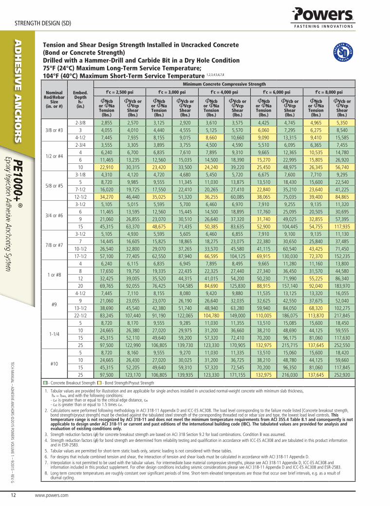
Tension and Shear Design Strength Installed in Uncracked Concrete (Bond or Concrete Strength)Drilled with a Hammer-Drill and Carbide Bit in a Dry Hole Condition75°F (24°C) Maximum Long-Term Service Temperature;104°F (40°C) Maximum Short-Term Service Temperature 1,2,3,4,5,6,7,8
Nominal Rod/Rebar
Size(in. or #)
Embed.Depth
hef
(in.)
Minimum Concrete Compressive Strength
f'c = 2,500 psi f'c = 3,000 psi f'c = 4,000 psi f'c = 6,000 psi f'c = 8,000 psi
ΦNcbor ΦNaTension
(lbs.)
ΦVcb or ΦVcpShear(lbs.)
ΦNcbor ΦNaTension
(lbs.)
ΦVcb or ΦVcpShear(lbs.)
ΦNcbor ΦNaTension
(lbs.)
ΦVcb or ΦVcpShear(lbs.)
ΦNcbor ΦNaTension
(lbs.)
ΦVcb or ΦVcpShear(lbs.)
ΦNcbor ΦNaTension
(lbs.)
ΦVcb or ΦVcpShear(lbs.)
3/8 or #32-3/8 2,855 2,570 3,125 2,920 3,610 3,575 4,425 4,745 4,965 5,350
3 4,055 4,010 4,440 4,555 5,125 5,570 6,060 7,295 6,275 8,5404-1/2 7,445 7,935 8,155 9,015 8,660 10,660 9,090 13,315 9,410 15,585
1/2 or #4
2-3/4 3,555 3,305 3,895 3,755 4,500 4,590 5,510 6,095 6,365 7,4554 6,240 6,700 6,835 7,610 7,895 9,310 9,665 12,365 10,535 14,7806 11,465 13,235 12,560 15,035 14,500 18,390 15,270 22,995 15,805 26,92010 22,910 30,315 23,420 33,500 24,240 39,220 25,450 48,975 26,345 56,740
5/8 or #5
3-1/8 4,310 4,120 4,720 4,680 5,450 5,720 6,675 7,600 7,710 9,2955 8,720 9,985 9,555 11,345 11,030 13,875 13,510 18,430 15,600 22,540
7-1/2 16,020 19,725 17,550 22,410 20,265 27,410 22,840 35,210 23,640 41,22512-1/2 34,270 46,440 35,025 51,320 36,255 60,085 38,065 75,035 39,400 84,865
3/4 or #6
3-1/2 5,105 5,015 5,595 5,700 6,460 6,970 7,910 9,255 9,135 11,3206 11,465 13,595 12,560 15,445 14,500 18,895 17,760 25,095 20,505 30,6959 21,060 26,855 23,070 30,510 26,640 37,320 31,740 49,025 32,855 57,39515 45,315 63,370 48,675 71,435 50,385 83,635 52,900 104,445 54,755 117,935
7/8 or #7
3-1/2 5,105 4,930 5,595 5,605 6,460 6,855 7,910 9,100 9,135 11,1307 14,445 16,605 15,825 18,865 18,275 23,075 22,380 30,650 25,840 37,485
10-1/2 26,540 32,800 29,070 37,265 33,570 45,580 41,115 60,540 43,425 71,45017-1/2 57,100 77,405 62,550 87,940 66,595 104,125 69,915 130,030 72,370 152,235
1 or #8
4 6,240 6,115 6,835 6,945 7,895 8,495 9,665 11,280 11,160 13,8008 17,650 19,750 19,335 22,435 22,325 27,440 27,340 36,450 31,570 44,58012 32,425 39,005 35,520 44,315 41,015 54,200 50,230 71,990 55,225 86,34020 69,765 92,055 76,425 104,585 84,690 125,830 88,915 157,140 92,040 183,970
#9
4-1/2 7,445 7,110 8,155 8,080 9,420 9,880 11,535 13,125 13,320 16,0559 21,060 23,055 23,070 26,190 26,640 32,035 32,625 42,550 37,675 52,040
13-1/2 38,690 45,540 42,380 51,740 48,940 63,280 59,940 84,050 68,320 102,27522-1/2 83,245 107,440 91,190 122,065 104,780 149,000 110,005 186,075 113,870 217,845
1-1/4
5 8,720 8,170 9,555 9,285 11,030 11,355 13,510 15,085 15,600 18,45010 24,665 26,380 27,020 29,975 31,200 36,660 38,210 48,690 44,125 59,55515 45,315 52,110 49,640 59,200 57,320 72,410 70,200 96,175 81,060 117,63025 97,500 122,990 106,805 139,730 123,330 170,905 132,975 215,715 137,645 252,550
#10
5 8,720 8,160 9,555 9,270 11,030 11,335 13,510 15,060 15,600 18,42010 24,665 26,430 27,020 30,025 31,200 36,725 38,210 48,780 44,125 59,66015 45,315 52,205 49,640 59,310 57,320 72,545 70,200 96,350 81,060 117,84525 97,500 123,170 106,805 139,935 123,330 171,155 132,975 216,030 137,645 252,920
■ - Concrete Breakout Strength ■ - Bond Strength/Pryout Strength
1. Tabular values are provided for illustration and are applicable for single anchors installed in uncracked normal-weight concrete with minimum slab thickness, ha = hmin, and with the following conditions: - ca1 is greater than or equal to the critical edge distance, cac - ca2 is greater than or equal to 1.5 times ca1.
2. Calculations were performed following methodology in ACI 318-11 Appendix D and ICC-ES AC308. The load level corresponding to the failure mode listed [Concrete breakout strength, bond strength/pryout strength] must be checked against the tabulated steel strength of the corresponding threaded rod or rebar size and type, the lowest load level controls. This temperature range is not recognized by ACI 318-11 and does not meet the minimum temperature requirements from ACI 355.4 Table 8.1 and consequently is not applicable to design under ACI 318-11 or current and past editions of the international building code (IBC). The tabulated values are provided for analysis and evaluation of existing conditions only.
3. Strength reduction factors (f) for concrete breakout strength are based on ACI 318 Section 9.2 for load combinations. Condition B was assumed. 4. Strength reduction factors (f) for bond strength are determined from reliability testing and qualification in accordance with ICC-ES AC308 and are tabulated in this product information
and in ESR-2583.5. Tabular values are permitted for short-term static loads only, seismic loading is not considered with these tables. 6. For designs that include combined tension and shear, the interaction of tension and shear loads must be calculated in accordance with ACI 318-11 Appendix D.7. Interpolation is not permitted to be used with the tabular values. For intermediate base material compressive strengths, please see ACI 318-11 Appendix D, ICC-ES AC308 and
information included in this product supplement. For other design conditions including seismic considerations please see ACI 318-11 Appendix D and ICC-ES AC308 and ESR-2583. 8. Long term concrete temperatures are roughly constant over significant periods of time. Short-term elevated temperatures are those that occur over brief intervals, e.g. as a result of
diurnal cycling.
www.powers.com 13
aD
hesiV
e a
nch
or
s
STReNGTH DeSIGN (SD)
TECH
MAN
UAL
– AD
HESI
VE A
NCH
ORS
©20
15 P
OW
ERS
VO
LUM
E 1
– 9/
2015
– R
EV. G
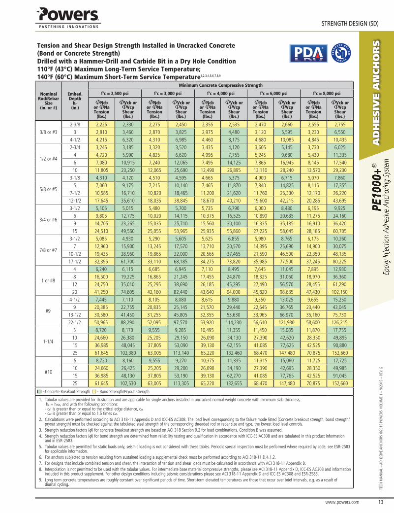
Tension and Shear Design Strength Installed in Uncracked Concrete(Bond or Concrete Strength)Drilled with a Hammer-Drill and Carbide Bit in a Dry Hole Condition110°F (43°C) Maximum Long-Term Service Temperature; 140°F (60°C) Maximum Short-Term Service Temperature1,2,3,4,5,6,7,8,9
®
Nominal Rod/Rebar
Size(in. or #)
Embed.Depth
hef
(in.)
Minimum Concrete Compressive Strength
f'c = 2,500 psi f'c = 3,000 psi f'c = 4,000 psi f'c = 6,000 psi f'c = 8,000 psi
ΦNcbor ΦNaTension
(lbs.)
ΦVcb or ΦVcpShear(lbs.)
ΦNcbor ΦNaTension
(lbs.)
ΦVcb or ΦVcpShear(lbs.)
ΦNcbor ΦNaTension
(lbs.)
ΦVcb or ΦVcpShear(lbs.)
ΦNcbor ΦNaTension
(lbs.)
ΦVcb or ΦVcpShear(lbs.)
ΦNcbor ΦNaTension
(lbs.)
ΦVcb or ΦVcpShear(lbs.)
3/8 or #32-3/8 2,225 2,330 2,275 2,450 2,355 2,535 2,470 2,660 2,555 2,755
3 2,810 3,460 2,870 3,825 2,975 4,480 3,120 5,595 3,230 6,5504-1/2 4,215 6,320 4,310 6,985 4,460 8,175 4,680 10,085 4,845 10,435
1/2 or #4
2-3/4 3,245 3,185 3,320 3,520 3,435 4,120 3,605 5,145 3,730 6,0254 4,720 5,990 4,825 6,620 4,995 7,755 5,245 9,680 5,430 11,3356 7,080 10,915 7,240 12,065 7,495 14,125 7,865 16,945 8,145 17,54010 11,805 23,250 12,065 25,690 12,490 26,895 13,110 28,240 13,570 29,230
5/8 or #5
3-1/8 4,310 4,120 4,510 4,595 4,665 5,375 4,900 6,715 5,070 7,8605 7,060 9,175 7,215 10,140 7,465 11,870 7,840 14,825 8,115 17,355
7-1/2 10,585 16,710 10,820 18,465 11,200 21,620 11,760 25,330 12,170 26,22012-1/2 17,645 35,610 18,035 38,845 18,670 40,210 19,600 42,215 20,285 43,695
3/4 or #6
3-1/2 5,105 5,015 5,480 5,700 5,735 6,790 6,000 8,480 6,195 9,9256 9,805 12,775 10,020 14,115 10,375 16,525 10,890 20,635 11,275 24,1609 14,705 23,265 15,035 25,710 15,560 30,100 16,335 35,185 16,910 36,42015 24,510 49,560 25,055 53,965 25,935 55,860 27,225 58,645 28,185 60,705
7/8 or #7
3-1/2 5,085 4,930 5,290 5,605 5,625 6,855 5,980 8,765 6,175 10,2607 12,960 15,900 13,245 17,570 13,710 20,570 14,395 25,690 14,900 30,075
10-1/2 19,435 28,960 19,865 32,000 20,565 37,465 21,590 46,500 22,350 48,13517-1/2 32,395 61,700 33,110 68,185 34,275 73,820 35,985 77,500 37,245 80,225
1 or #8
4 6,240 6,115 6,685 6,945 7,110 8,495 7,645 11,045 7,895 12,9308 16,500 19,225 16,865 21,245 17,455 24,870 18,325 31,060 18,970 36,36012 24,750 35,010 25,295 38,690 26,185 45,295 27,490 56,570 28,455 61,29020 41,250 74,605 42,160 82,440 43,640 94,000 45,820 98,685 47,430 102,150
#9
4-1/2 7,445 7,110 8,105 8,080 8,615 9,880 9,350 13,025 9,655 15,2509 20,385 22,755 20,835 25,145 21,570 29,440 22,645 36,765 23,440 43,045
13-1/2 30,580 41,450 31,255 45,805 32,355 53,630 33,965 66,970 35,160 75,73022-1/2 50,965 88,290 52,095 97,570 53,920 114,230 56,610 121,930 58,600 126,215
1-1/4
5 8,720 8,170 9,555 9,285 10,495 11,355 11,450 15,085 11,870 17,75510 24,660 26,380 25,205 29,150 26,090 34,130 27,390 42,620 28,350 49,89515 36,985 48,045 37,805 53,090 39,130 62,155 41,085 77,625 42,525 90,88025 61,645 102,380 63,005 113,140 65,220 132,460 68,470 147,480 70,875 152,660
#10
5 8,720 8,160 9,555 9,270 10,375 11,335 11,315 15,060 11,725 17,72510 24,660 26,425 25,205 29,200 26,090 34,190 27,390 42,695 28,350 49,98515 36,985 48,130 37,805 53,190 39,130 62,270 41,085 77,765 42,525 91,04525 61,645 102,530 63,005 113,305 65,220 132,655 68,470 147,480 70,875 152,660
■ - Concrete Breakout Strength ■ - Bond Strength/Pryout Strength
1. Tabular values are provided for illustration and are applicable for single anchors installed in uncracked normal-weight concrete with minimum slab thickness, ha = hmin, and with the following conditions: - ca1 is greater than or equal to the critical edge distance, cac - ca2 is greater than or equal to 1.5 times ca1.
2. Calculations were performed according to ACI 318-11 Appendix D and ICC-ES AC308. The load level corresponding to the failure mode listed [Concrete breakout strength, bond strength/pryout strength] must be checked against the tabulated steel strength of the corresponding threaded rod or rebar size and type, the lowest load level controls.
3. Strength reduction factors (f) for concrete breakout strength are based on ACI 318 Section 9.2 for load combinations. Condition B was assumed. 4. Strength reduction factors (f) for bond strength are determined from reliability testing and qualification in accordance with ICC-ES AC308 and are tabulated in this product information
and in ESR-2583.5. Tabular values are permitted for static loads only, seismic loading is not considered with these tables. Periodic special inspection must be performed where required by code, see ESR-2583
for applicable information.6. For anchors subjected to tension resulting from sustained loading a supplemental check must be performed according to ACI 318-11 D.4.1.2.7. For designs that include combined tension and shear, the interaction of tension and shear loads must be calculated in accordance with ACI 318-11 Appendix D.8. Interpolation is not permitted to be used with the tabular values. For intermediate base material compressive strengths, please see ACI 318-11 Appendix D, ICC-ES AC308 and information
included in this product supplement. For other design conditions including seismic considerations please see ACI 318-11 Appendix D and ICC-ES AC308 and ESR-2583. 9. Long term concrete temperatures are roughly constant over significant periods of time. Short-term elevated temperatures are those that occur over brief intervals, e.g. as a result of
diurnal cycling.
aD
hesiV
e a
nch
or
s
www.powers.com 14
TECH MAN
UAL – ADHESIVE ANCHO
RS ©2015 PO
WERS VO
LUME 1 – 9/2015 – REV. G
STReNGTH DeSIGN (SD)
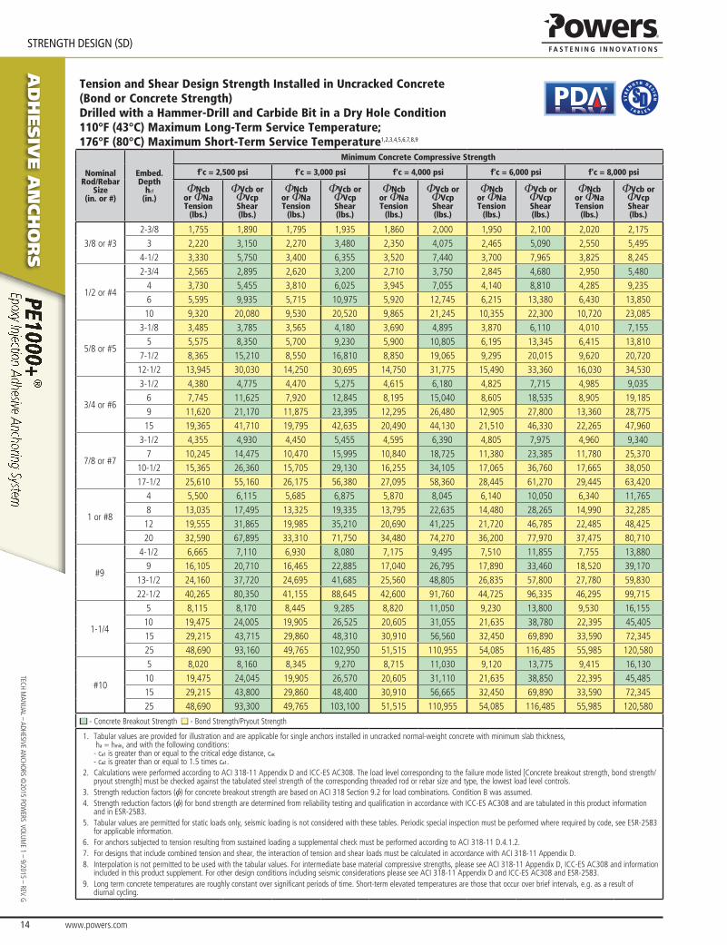
Tension and Shear Design Strength Installed in Uncracked Concrete(Bond or Concrete Strength)Drilled with a Hammer-Drill and Carbide Bit in a Dry Hole Condition110°F (43°C) Maximum Long-Term Service Temperature;176°F (80°C) Maximum Short-Term Service Temperature1,2,3,4,5,6,7,8,9
®
Nominal Rod/Rebar
Size(in. or #)
Embed.Depth
hef
(in.)
Minimum Concrete Compressive Strength
f'c = 2,500 psi f'c = 3,000 psi f'c = 4,000 psi f'c = 6,000 psi f'c = 8,000 psi
ΦNcbor ΦNaTension
(lbs.)
ΦVcb or ΦVcpShear(lbs.)
ΦNcbor ΦNaTension
(lbs.)
ΦVcb or ΦVcpShear(lbs.)
ΦNcbor ΦNaTension
(lbs.)
ΦVcb or ΦVcpShear(lbs.)
ΦNcbor ΦNaTension
(lbs.)
ΦVcb or ΦVcpShear(lbs.)
ΦNcbor ΦNaTension
(lbs.)
ΦVcb or ΦVcpShear(lbs.)
3/8 or #32-3/8 1,755 1,890 1,795 1,935 1,860 2,000 1,950 2,100 2,020 2,175
3 2,220 3,150 2,270 3,480 2,350 4,075 2,465 5,090 2,550 5,4954-1/2 3,330 5,750 3,400 6,355 3,520 7,440 3,700 7,965 3,825 8,245
1/2 or #4
2-3/4 2,565 2,895 2,620 3,200 2,710 3,750 2,845 4,680 2,950 5,4804 3,730 5,455 3,810 6,025 3,945 7,055 4,140 8,810 4,285 9,2356 5,595 9,935 5,715 10,975 5,920 12,745 6,215 13,380 6,430 13,85010 9,320 20,080 9,530 20,520 9,865 21,245 10,355 22,300 10,720 23,085
5/8 or #5
3-1/8 3,485 3,785 3,565 4,180 3,690 4,895 3,870 6,110 4,010 7,1555 5,575 8,350 5,700 9,230 5,900 10,805 6,195 13,345 6,415 13,810
7-1/2 8,365 15,210 8,550 16,810 8,850 19,065 9,295 20,015 9,620 20,72012-1/2 13,945 30,030 14,250 30,695 14,750 31,775 15,490 33,360 16,030 34,530
3/4 or #6
3-1/2 4,380 4,775 4,470 5,275 4,615 6,180 4,825 7,715 4,985 9,0356 7,745 11,625 7,920 12,845 8,195 15,040 8,605 18,535 8,905 19,1859 11,620 21,170 11,875 23,395 12,295 26,480 12,905 27,800 13,360 28,77515 19,365 41,710 19,795 42,635 20,490 44,130 21,510 46,330 22,265 47,960
7/8 or #7
3-1/2 4,355 4,930 4,450 5,455 4,595 6,390 4,805 7,975 4,960 9,3407 10,245 14,475 10,470 15,995 10,840 18,725 11,380 23,385 11,780 25,370
10-1/2 15,365 26,360 15,705 29,130 16,255 34,105 17,065 36,760 17,665 38,05017-1/2 25,610 55,160 26,175 56,380 27,095 58,360 28,445 61,270 29,445 63,420
1 or #8
4 5,500 6,115 5,685 6,875 5,870 8,045 6,140 10,050 6,340 11,7658 13,035 17,495 13,325 19,335 13,795 22,635 14,480 28,265 14,990 32,28512 19,555 31,865 19,985 35,210 20,690 41,225 21,720 46,785 22,485 48,42520 32,590 67,895 33,310 71,750 34,480 74,270 36,200 77,970 37,475 80,710
#9
4-1/2 6,665 7,110 6,930 8,080 7,175 9,495 7,510 11,855 7,755 13,8809 16,105 20,710 16,465 22,885 17,040 26,795 17,890 33,460 18,520 39,170
13-1/2 24,160 37,720 24,695 41,685 25,560 48,805 26,835 57,800 27,780 59,83022-1/2 40,265 80,350 41,155 88,645 42,600 91,760 44,725 96,335 46,295 99,715
1-1/4
5 8,115 8,170 8,445 9,285 8,820 11,050 9,230 13,800 9,530 16,15510 19,475 24,005 19,905 26,525 20,605 31,055 21,635 38,780 22,395 45,40515 29,215 43,715 29,860 48,310 30,910 56,560 32,450 69,890 33,590 72,34525 48,690 93,160 49,765 102,950 51,515 110,955 54,085 116,485 55,985 120,580
#10
5 8,020 8,160 8,345 9,270 8,715 11,030 9,120 13,775 9,415 16,13010 19,475 24,045 19,905 26,570 20,605 31,110 21,635 38,850 22,395 45,48515 29,215 43,800 29,860 48,400 30,910 56,665 32,450 69,890 33,590 72,34525 48,690 93,300 49,765 103,100 51,515 110,955 54,085 116,485 55,985 120,580
■ - Concrete Breakout Strength ■ - Bond Strength/Pryout Strength
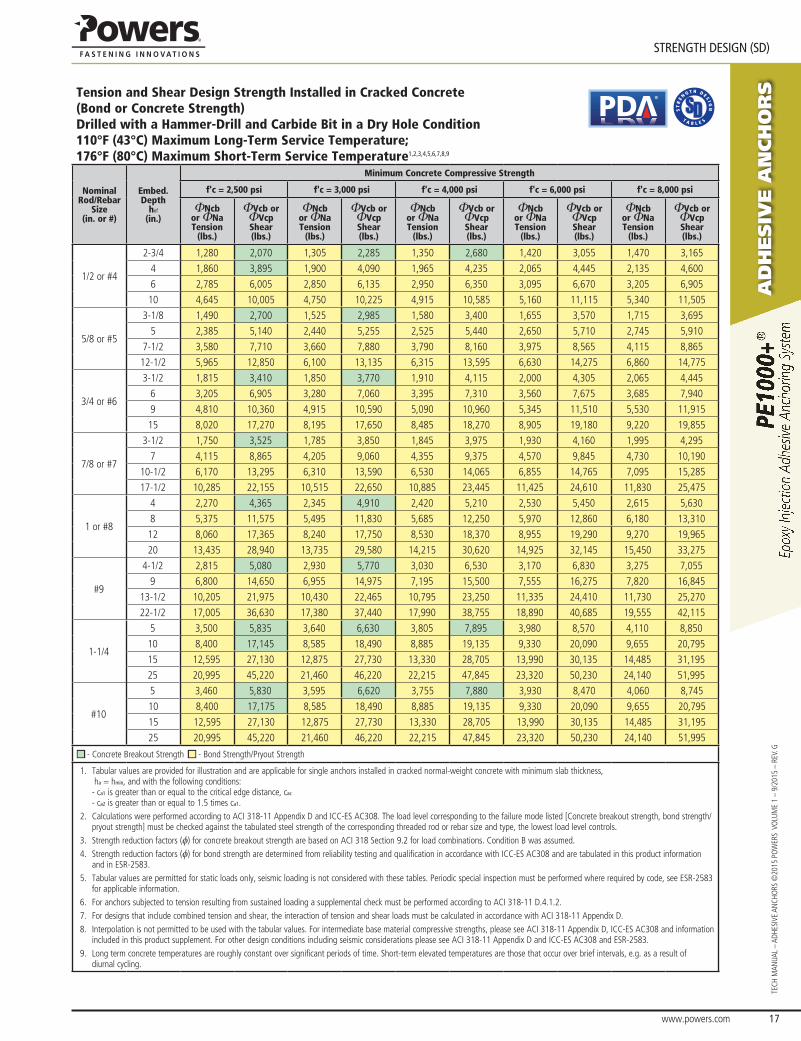
1. Tabular values are provided for illustration and are applicable for single anchors installed in uncracked normal-weight concrete with minimum slab thickness, ha = hmin, and with the following conditions: - ca1 is greater than or equal to the critical edge distance, cac - ca2 is greater than or equal to 1.5 times ca1.
2. Calculations were performed according to ACI 318-11 Appendix D and ICC-ES AC308. The load level corresponding to the failure mode listed [Concrete breakout strength, bond strength/pryout strength] must be checked against the tabulated steel strength of the corresponding threaded rod or rebar size and type, the lowest load level controls.
3. Strength reduction factors (f) for concrete breakout strength are based on ACI 318 Section 9.2 for load combinations. Condition B was assumed. 4. Strength reduction factors (f) for bond strength are determined from reliability testing and qualification in accordance with ICC-ES AC308 and are tabulated in this product information
and in ESR-2583.5. Tabular values are permitted for static loads only, seismic loading is not considered with these tables. Periodic special inspection must be performed where required by code, see ESR-2583
for applicable information.6. For anchors subjected to tension resulting from sustained loading a supplemental check must be performed according to ACI 318-11 D.4.1.2.7. For designs that include combined tension and shear, the interaction of tension and shear loads must be calculated in accordance with ACI 318-11 Appendix D.8. Interpolation is not permitted to be used with the tabular values. For intermediate base material compressive strengths, please see ACI 318-11 Appendix D, ICC-ES AC308 and information
included in this product supplement. For other design conditions including seismic considerations please see ACI 318-11 Appendix D and ICC-ES AC308 and ESR-2583. 9. Long term concrete temperatures are roughly constant over significant periods of time. Short-term elevated temperatures are those that occur over brief intervals, e.g. as a result of
diurnal cycling.
www.powers.com 15
aD
hesiV
e a
nch
or
s
STReNGTH DeSIGN (SD)
TECH
MAN
UAL
– AD
HESI
VE A
NCH
ORS
©20
15 P
OW
ERS
VO
LUM
E 1
– 9/
2015
– R
EV. G
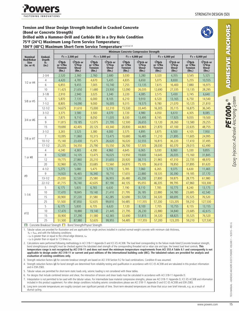
Tension and Shear Design Strength Installed in Cracked Concrete(Bond or Concrete Strength)Drilled with a Hammer-Drill and Carbide Bit in a Dry Hole Condition75°F (24°C) Maximum Long-Term Service Temperature;104°F (40°C) Maximum Short-Term Service Temperature1,2,3,4,5,6,7,8
Nominal Rod/Rebar
Size(in. or #)
Embed.Depth
hef
(in.)
Minimum Concrete Compressive Strength
f'c = 2,500 psi f'c = 3,000 psi f'c = 4,000 psi f'c = 6,000 psi f'c = 8,000 psi
ΦNcbor ΦNaTension
(lbs.)
ΦVcb or ΦVcpShear(lbs.)
ΦNcbor ΦNaTension
(lbs.)
ΦVcb or ΦVcpShear(lbs.)
ΦNcbor ΦNaTension
(lbs.)
ΦVcb or ΦVcpShear(lbs.)
ΦNcbor ΦNaTension
(lbs.)
ΦVcb or ΦVcpShear(lbs.)
ΦNcbor ΦNaTension
(lbs.)
ΦVcb or ΦVcpShear(lbs.)
1/2 or #4
2-3/4 2,520 2,360 2,760 2,680 3,030 3,280 3,320 4,355 3,545 5,325
4 4,420 4,785 4,670 5,435 4,835 6,650 5,075 8,830 5,255 10,555
6 6,855 9,455 7,005 10,740 7,255 13,135 7,615 16,400 7,880 16,975
10 11,425 21,650 11,680 23,930 12,090 26,035 12,690 27,335 13,135 28,295
5/8 or #5
3-1/8 2,910 2,940 3,025 3,340 3,220 4,085 3,515 5,430 3,745 6,640
5 5,870 7,135 6,000 8,105 6,210 9,910 6,520 13,165 6,750 14,540
7-1/2 8,805 14,090 9,000 16,005 9,315 19,575 9,780 21,070 10,125 21,810
12-1/2 14,675 31,610 15,000 32,310 15,530 33,445 16,305 35,115 16,875 36,345
3/4 or #6
3-1/2 3,375 3,580 3,500 4,070 3,720 4,980 4,050 6,610 4,305 8,085
6 7,875 9,710 8,050 11,035 8,330 13,495 8,745 17,925 9,055 19,500
9 11,815 19,185 12,075 21,795 12,500 26,655 13,120 28,260 13,580 29,255
15 19,690 42,405 20,125 43,340 20,830 44,865 21,870 47,100 22,635 48,755
7/8 or #7
3-1/2 3,265 3,525 3,380 4,000 3,575 4,895 3,875 6,500 4,105 7,950
7 10,095 11,860 10,315 13,475 10,680 16,485 11,210 21,895 11,605 24,995
10-1/2 15,140 23,430 15,475 26,620 16,020 32,555 16,815 36,220 17,410 37,495
17-1/2 25,235 54,350 25,790 55,550 26,700 57,505 28,030 60,370 29,015 62,490
1 or #8
4 4,240 4,365 4,390 4,960 4,645 6,065 5,030 8,060 5,330 9,855
8 12,500 14,105 13,475 16,025 13,950 19,600 14,645 26,035 15,160 31,845
12 19,775 27,860 20,210 31,655 20,920 38,715 21,965 47,310 22,735 48,970
20 32,960 65,755 33,685 72,560 34,870 75,105 36,610 78,850 37,895 81,620
#9
4-1/2 5,275 5,080 5,475 5,770 5,785 7,060 6,265 9,375 6,630 11,465
9 14,920 16,465 16,340 18,710 17,655 22,880 18,535 30,390 19,185 37,170
13-1/2 25,030 32,530 25,580 36,955 26,480 45,200 27,800 59,875 28,775 61,980
22-1/2 41,715 76,740 42,635 87,190 44,135 95,055 46,335 99,795 47,960 103,300
1-1/4
5 6,175 5,835 6,765 6,630 7,190 8,110 7,785 10,775 8,240 13,175
10 17,470 18,845 19,140 21,410 21,795 26,185 22,880 34,780 23,685 42,540
15 30,900 37,220 31,580 42,285 32,690 51,720 34,320 68,695 35,525 76,520
25 51,500 87,850 52,635 99,810 54,485 117,355 57,200 123,205 59,210 127,530
#10
5 6,175 5,830 6,735 6,620 7,120 8,100 7,705 10,755 8,155 13,155
10 17,470 18,880 19,140 21,445 21,795 26,230 22,880 34,840 23,685 42,615
15 30,900 37,290 31,580 42,365 32,690 51,815 34,320 68,825 35,525 76,520
25 51,500 87,980 52,635 99,955 54,485 117,355 57,200 123,205 59,210 127,530
■ - Concrete Breakout Strength ■ - Bond Strength/Pryout Strength1. Tabular values are provided for illustration and are applicable for single anchors installed in cracked normal-weight concrete with minimum slab thickness,
ha = hmin, and with the following conditions: - ca1 is greater than or equal to the critical edge distance, cac - ca2 is greater than or equal to 1.5 times ca1.
2. Calculations were performed following methodology in ACI 318-11 Appendix D and ICC-ES AC308. The load level corresponding to the failure mode listed [Concrete breakout strength, bond strength/pryout strength] must be checked against the tabulated steel strength of the corresponding threaded rod or rebar size and type, the lowest load level controls. This temperature range is not recognized by ACI 318-11 and does not meet the minimum temperature requirements from ACI 355.4 Table 8.1 and consequently is not applicable to design under ACI 318-11 or current and past editions of the international building code (IBC). The tabulated values are provided for analysis and evaluation of existing conditions only.
3. Strength reduction factors (f) for concrete breakout strength are based on ACI 318 Section 9.2 for load combinations. Condition B was assumed. 4. Strength reduction factors (f) for bond strength are determined from reliability testing and qualification in accordance with ICC-ES AC308 and are tabulated in this product information
and in ESR-2583.5. Tabular values are permitted for short-term static loads only, seismic loading is not considered with these tables. 6. For designs that include combined tension and shear, the interaction of tension and shear loads must be calculated in accordance with ACI 318-11 Appendix D.7. Interpolation is not permitted to be used with the tabular values. For intermediate base material compressive strengths, please see ACI 318-11 Appendix D, ICC-ES AC308 and information
included in this product supplement. For other design conditions including seismic considerations please see ACI 318-11 Appendix D and ICC-ES AC308 and ESR-2583. 8. Long term concrete temperatures are roughly constant over significant periods of time. Short-term elevated temperatures are those that occur over brief intervals, e.g. as a result of
diurnal cycling.
aD
hesiV
e a
nch
or
s
www.powers.com 16
TECH MAN
UAL – ADHESIVE ANCHO
RS ©2015 PO
WERS VO
LUME 1 – 9/2015 – REV. G
STReNGTH DeSIGN (SD)
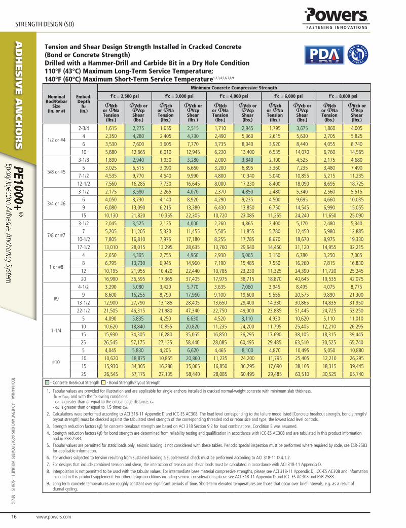
Tension and Shear Design Strength Installed in Cracked Concrete(Bond or Concrete Strength)Drilled with a Hammer-Drill and Carbide Bit in a Dry Hole Condition110°F (43°C) Maximum Long-Term Service Temperature;140°F (60°C) Maximum Short-Term Service Temperature1,2,3,4,5,6,7,8,9
®
Nominal Rod/Rebar
Size(in. or #)
Embed.Depth
hef
(in.)
Minimum Concrete Compressive Strength
f'c = 2,500 psi f'c = 3,000 psi f'c = 4,000 psi f'c = 6,000 psi f'c = 8,000 psi
ΦNcbor ΦNaTension
(lbs.)
ΦVcb or ΦVcpShear(lbs.)
ΦNcbor ΦNaTension
(lbs.)
ΦVcb or ΦVcpShear(lbs.)
ΦNcbor ΦNaTension
(lbs.)
ΦVcb or ΦVcpShear(lbs.)
ΦNcbor ΦNaTension
(lbs.)
ΦVcb or ΦVcpShear(lbs.)
ΦNcbor ΦNaTension
(lbs.)
ΦVcb or ΦVcpShear(lbs.)
1/2 or #4
2-3/4 1,615 2,275 1,655 2,515 1,710 2,945 1,795 3,675 1,860 4,005
4 2,350 4,280 2,405 4,730 2,490 5,360 2,615 5,630 2,705 5,825
6 3,530 7,600 3,605 7,770 3,735 8,040 3,920 8,440 4,055 8,740
10 5,880 12,665 6,010 12,945 6,220 13,400 6,535 14,070 6,760 14,565
5/8 or #5
3-1/8 1,890 2,940 1,930 3,280 2,000 3,840 2,100 4,525 2,175 4,680
5 3,025 6,515 3,090 6,660 3,200 6,895 3,360 7,235 3,480 7,490
7-1/2 4,535 9,770 4,640 9,990 4,800 10,340 5,040 10,855 5,215 11,235
12-1/2 7,560 16,285 7,730 16,645 8,000 17,230 8,400 18,090 8,695 18,725
3/4 or #6
3-1/2 2,175 3,580 2,265 4,070 2,370 4,850 2,480 5,340 2,560 5,515
6 4,050 8,730 4,140 8,920 4,290 9,235 4,500 9,695 4,660 10,035
9 6,080 13,090 6,215 13,380 6,430 13,850 6,750 14,545 6,990 15,055
15 10,130 21,820 10,355 22,305 10,720 23,085 11,255 24,240 11,650 25,090
7/8 or #7
3-1/2 2,045 3,525 2,125 4,000 2,260 4,865 2,400 5,170 2,480 5,340
7 5,205 11,205 5,320 11,455 5,505 11,855 5,780 12,450 5,980 12,885
10-1/2 7,805 16,810 7,975 17,180 8,255 17,785 8,670 18,670 8,975 19,330
17-1/2 13,010 28,015 13,295 28,635 13,760 29,640 14,450 31,120 14,955 32,215
1 or #8
4 2,650 4,365 2,755 4,960 2,930 6,065 3,150 6,780 3,250 7,005
8 6,795 13,730 6,945 14,960 7,190 15,485 7,550 16,260 7,815 16,830
12 10,195 21,955 10,420 22,440 10,785 23,230 11,325 24,390 11,720 25,245
20 16,990 36,595 17,365 37,405 17,975 38,715 18,870 40,645 19,535 42,075
#9
4-1/2 3,290 5,080 3,420 5,770 3,635 7,060 3,945 8,495 4,075 8,775
9 8,600 16,255 8,790 17,960 9,100 19,600 9,555 20,575 9,890 21,300
13-1/2 12,900 27,790 13,185 28,405 13,650 29,400 14,330 30,865 14,835 31,950
22-1/2 21,505 46,315 21,980 47,340 22,750 49,000 23,885 51,445 24,725 53,250
1-1/4
5 4,090 5,835 4,250 6,630 4,520 8,110 4,930 10,620 5,110 11,010
10 10,620 18,840 10,855 20,820 11,235 24,200 11,795 25,405 12,210 26,295
15 15,930 34,305 16,280 35,065 16,850 36,295 17,690 38,105 18,315 39,445
25 26,545 57,175 27,135 58,440 28,085 60,495 29,485 63,510 30,525 65,740
#10
5 4,045 5,830 4,205 6,620 4,465 8,100 4,870 10,495 5,050 10,880
10 10,620 18,875 10,855 20,860 11,235 24,200 11,795 25,405 12,210 26,295
15 15,930 34,305 16,280 35,065 16,850 36,295 17,690 38,105 18,315 39,445
25 26,545 57,175 27,135 58,440 28,085 60,495 29,485 63,510 30,525 65,740
■ - Concrete Breakout Strength ■ - Bond Strength/Pryout Strength
1. Tabular values are provided for illustration and are applicable for single anchors installed in cracked normal-weight concrete with minimum slab thickness, ha = hmin, and with the following conditions: - ca1 is greater than or equal to the critical edge distance, cac - ca2 is greater than or equal to 1.5 times ca1.
2. Calculations were performed according to ACI 318-11 Appendix D and ICC-ES AC308. The load level corresponding to the failure mode listed [Concrete breakout strength, bond strength/pryout strength] must be checked against the tabulated steel strength of the corresponding threaded rod or rebar size and type, the lowest load level controls.
3. Strength reduction factors (f) for concrete breakout strength are based on ACI 318 Section 9.2 for load combinations. Condition B was assumed. 4. Strength reduction factors (f) for bond strength are determined from reliability testing and qualification in accordance with ICC-ES AC308 and are tabulated in this product information
and in ESR-2583.5. Tabular values are permitted for static loads only, seismic loading is not considered with these tables. Periodic special inspection must be performed where required by code, see ESR-2583
for applicable information.6. For anchors subjected to tension resulting from sustained loading a supplemental check must be performed according to ACI 318-11 D.4.1.2.7. For designs that include combined tension and shear, the interaction of tension and shear loads must be calculated in accordance with ACI 318-11 Appendix D.8. Interpolation is not permitted to be used with the tabular values. For intermediate base material compressive strengths, please see ACI 318-11 Appendix D, ICC-ES AC308 and information
included in this product supplement. For other design conditions including seismic considerations please see ACI 318-11 Appendix D and ICC-ES AC308 and ESR-2583. 9. Long term concrete temperatures are roughly constant over significant periods of time. Short-term elevated temperatures are those that occur over brief intervals, e.g. as a result of
diurnal cycling.
www.powers.com 17
aD
hesiV
e a
nch
or
s
STReNGTH DeSIGN (SD)
TECH
MAN
UAL
– AD
HESI
VE A
NCH
ORS
©20
15 P
OW
ERS
VO
LUM
E 1
– 9/
2015
– R
EV. G
Tension and Shear Design Strength Installed in Cracked Concrete(Bond or Concrete Strength)Drilled with a Hammer-Drill and Carbide Bit in a Dry Hole Condition110°F (43°C) Maximum Long-Term Service Temperature;176°F (80°C) Maximum Short-Term Service Temperature1,2,3,4,5,6,7,8,9
®
Nominal Rod/Rebar
Size(in. or #)
Embed.Depth
hef
(in.)
Minimum Concrete Compressive Strength
f'c = 2,500 psi f'c = 3,000 psi f'c = 4,000 psi f'c = 6,000 psi f'c = 8,000 psi
ΦNcbor ΦNaTension
(lbs.)
ΦVcb or ΦVcpShear(lbs.)
ΦNcbor ΦNaTension
(lbs.)
ΦVcb or ΦVcpShear(lbs.)
ΦNcbor ΦNaTension
(lbs.)
ΦVcb or ΦVcpShear(lbs.)
ΦNcbor ΦNaTension
(lbs.)
ΦVcb or ΦVcpShear(lbs.)
ΦNcbor ΦNaTension
(lbs.)
ΦVcb or ΦVcpShear(lbs.)
1/2 or #4
2-3/4 1,280 2,070 1,305 2,285 1,350 2,680 1,420 3,055 1,470 3,165
4 1,860 3,895 1,900 4,090 1,965 4,235 2,065 4,445 2,135 4,600
6 2,785 6,005 2,850 6,135 2,950 6,350 3,095 6,670 3,205 6,905
10 4,645 10,005 4,750 10,225 4,915 10,585 5,160 11,115 5,340 11,505
5/8 or #5
3-1/8 1,490 2,700 1,525 2,985 1,580 3,400 1,655 3,570 1,715 3,695
5 2,385 5,140 2,440 5,255 2,525 5,440 2,650 5,710 2,745 5,910
7-1/2 3,580 7,710 3,660 7,880 3,790 8,160 3,975 8,565 4,115 8,865
12-1/2 5,965 12,850 6,100 13,135 6,315 13,595 6,630 14,275 6,860 14,775
3/4 or #6
3-1/2 1,815 3,410 1,850 3,770 1,910 4,115 2,000 4,305 2,065 4,445
6 3,205 6,905 3,280 7,060 3,395 7,310 3,560 7,675 3,685 7,940
9 4,810 10,360 4,915 10,590 5,090 10,960 5,345 11,510 5,530 11,915
15 8,020 17,270 8,195 17,650 8,485 18,270 8,905 19,180 9,220 19,855
7/8 or #7
3-1/2 1,750 3,525 1,785 3,850 1,845 3,975 1,930 4,160 1,995 4,295
7 4,115 8,865 4,205 9,060 4,355 9,375 4,570 9,845 4,730 10,190
10-1/2 6,170 13,295 6,310 13,590 6,530 14,065 6,855 14,765 7,095 15,285
17-1/2 10,285 22,155 10,515 22,650 10,885 23,445 11,425 24,610 11,830 25,475
1 or #8
4 2,270 4,365 2,345 4,910 2,420 5,210 2,530 5,450 2,615 5,630
8 5,375 11,575 5,495 11,830 5,685 12,250 5,970 12,860 6,180 13,310
12 8,060 17,365 8,240 17,750 8,530 18,370 8,955 19,290 9,270 19,965
20 13,435 28,940 13,735 29,580 14,215 30,620 14,925 32,145 15,450 33,275
#9
4-1/2 2,815 5,080 2,930 5,770 3,030 6,530 3,170 6,830 3,275 7,055
9 6,800 14,650 6,955 14,975 7,195 15,500 7,555 16,275 7,820 16,845
13-1/2 10,205 21,975 10,430 22,465 10,795 23,250 11,335 24,410 11,730 25,270
22-1/2 17,005 36,630 17,380 37,440 17,990 38,755 18,890 40,685 19,555 42,115
1-1/4
5 3,500 5,835 3,640 6,630 3,805 7,895 3,980 8,570 4,110 8,850
10 8,400 17,145 8,585 18,490 8,885 19,135 9,330 20,090 9,655 20,795
15 12,595 27,130 12,875 27,730 13,330 28,705 13,990 30,135 14,485 31,195
25 20,995 45,220 21,460 46,220 22,215 47,845 23,320 50,230 24,140 51,995
#10
5 3,460 5,830 3,595 6,620 3,755 7,880 3,930 8,470 4,060 8,745
10 8,400 17,175 8,585 18,490 8,885 19,135 9,330 20,090 9,655 20,795
15 12,595 27,130 12,875 27,730 13,330 28,705 13,990 30,135 14,485 31,195
25 20,995 45,220 21,460 46,220 22,215 47,845 23,320 50,230 24,140 51,995
■ - Concrete Breakout Strength ■ - Bond Strength/Pryout Strength
1. Tabular values are provided for illustration and are applicable for single anchors installed in cracked normal-weight concrete with minimum slab thickness, ha = hmin, and with the following conditions: - ca1 is greater than or equal to the critical edge distance, cac - ca2 is greater than or equal to 1.5 times ca1.
2. Calculations were performed according to ACI 318-11 Appendix D and ICC-ES AC308. The load level corresponding to the failure mode listed [Concrete breakout strength, bond strength/pryout strength] must be checked against the tabulated steel strength of the corresponding threaded rod or rebar size and type, the lowest load level controls.
3. Strength reduction factors (f) for concrete breakout strength are based on ACI 318 Section 9.2 for load combinations. Condition B was assumed. 4. Strength reduction factors (f) for bond strength are determined from reliability testing and qualification in accordance with ICC-ES AC308 and are tabulated in this product information
and in ESR-2583.5. Tabular values are permitted for static loads only, seismic loading is not considered with these tables. Periodic special inspection must be performed where required by code, see ESR-2583
for applicable information.6. For anchors subjected to tension resulting from sustained loading a supplemental check must be performed according to ACI 318-11 D.4.1.2.7. For designs that include combined tension and shear, the interaction of tension and shear loads must be calculated in accordance with ACI 318-11 Appendix D.8. Interpolation is not permitted to be used with the tabular values. For intermediate base material compressive strengths, please see ACI 318-11 Appendix D, ICC-ES AC308 and information
included in this product supplement. For other design conditions including seismic considerations please see ACI 318-11 Appendix D and ICC-ES AC308 and ESR-2583. 9. Long term concrete temperatures are roughly constant over significant periods of time. Short-term elevated temperatures are those that occur over brief intervals, e.g. as a result of
diurnal cycling.
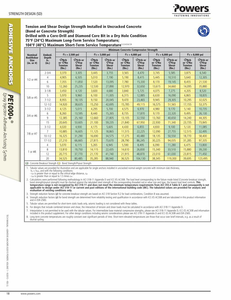
aD
hesiV
e a
nch
or
s
www.powers.com 18
TECH MAN
UAL – ADHESIVE ANCHO
RS ©2015 PO
WERS VO
LUME 1 – 9/2015 – REV. G
STReNGTH DeSIGN (SD)
Tension and Shear Design Strength Installed in Uncracked Concrete(Bond or Concrete Strength)Drilled with a Core-Drill and Diamond Core Bit in a Dry Hole Condition75°F (24°C) Maximum Long-Term Service Temperature;104°F (40°C) Maximum Short-Term Service Temperature1,2,3,4,5,6,7,8
Nominal Rod/Rebar
Size(in. or #)
Embed.Depth
hef
(in.)
Minimum Concrete Compressive Strength
f'c = 2,500 psi f'c = 3,000 psi f'c = 4,000 psi f'c = 6,000 psi f'c = 8,000 psi
ΦNcbor ΦNaTension
(lbs.)
ΦVcb or ΦVcpShear(lbs.)
ΦNcbor ΦNaTension
(lbs.)
ΦVcb or ΦVcpShear(lbs.)
ΦNcbor ΦNaTension
(lbs.)
ΦVcb or ΦVcpShear(lbs.)
ΦNcbor ΦNaTension
(lbs.)
ΦVcb or ΦVcpShear(lbs.)
ΦNcbor ΦNaTension
(lbs.)
ΦVcb or ΦVcpShear(lbs.)
1/2 or #4
2-3/4 3,370 3,305 3,445 3,755 3,565 4,470 3,745 5,585 3,875 6,540
4 4,905 6,505 5,010 7,190 5,190 8,415 5,445 10,510 5,640 12,305
6 7,355 11,850 7,520 13,095 7,780 15,330 8,170 19,145 8,455 21,530
10 12,260 25,235 12,530 27,890 12,970 32,650 13,615 34,660 14,095 35,880
5/8 or #5
3-1/8 3,450 4,120 3,600 4,680 3,840 5,725 4,075 7,275 4,205 8,520
5 5,970 9,960 6,100 11,005 6,315 12,885 6,630 16,090 6,865 18,835
7-1/2 8,955 18,135 9,150 20,045 9,470 23,465 9,945 29,305 10,295 32,025
12-1/2 14,920 38,635 15,250 42,695 15,785 49,115 16,575 51,565 17,155 53,375
3/4 or #6
3-1/2 4,125 5,015 4,295 5,700 4,575 6,970 4,980 9,170 5,140 10,735
6 8,260 13,595 8,440 15,265 8,735 17,870 9,170 22,320 9,495 26,130
9 12,385 25,160 12,660 27,805 13,105 32,550 13,760 40,650 14,240 44,305
15 20,645 53,605 21,100 59,235 21,840 67,950 22,930 71,340 23,735 73,845
7/8 or #7
3-1/2 4,020 4,930 4,175 5,605 4,430 6,855 4,830 9,100 5,120 11,085
7 10,885 16,605 11,125 18,865 11,515 22,225 12,090 27,755 12,515 32,495
10-1/2 16,325 31,290 16,690 34,575 17,275 40,480 18,135 50,550 18,770 58,400
17-1/2 27,210 66,665 27,815 73,670 28,790 86,245 30,225 94,035 31,285 97,335
1 or #8
4 5,070 6,115 5,265 6,945 5,590 8,495 6,090 11,280 6,475 13,800
8 13,810 19,750 14,115 22,435 14,610 26,830 15,340 33,510 15,880 39,230
12 20,715 37,770 21,170 41,740 21,915 48,870 23,010 61,030 23,815 71,450
20 34,525 80,485 35,285 88,940 36,525 104,130 38,345 119,300 39,695 123,495
■ - Concrete Breakout Strength ■ - Bond Strength/Pryout Strength
1. Tabular values are provided for illustration and are applicable for single anchors installed in uncracked normal-weight concrete with minimum slab thickness, ha = hmin, and with the following conditions: - ca1 is greater than or equal to the critical edge distance, cac - ca2 is greater than or equal to 1.5 times ca1.
2. Calculations were performed following methodology in ACI 318-11 Appendix D and ICC-ES AC308. The load level corresponding to the failure mode listed [Concrete breakout strength, bond strength/pryout strength] must be checked against the tabulated steel strength of the corresponding threaded rod or rebar size and type, the lowest load level controls. This temperature range is not recognized by ACI 318-11 and does not meet the minimum temperature requirements from ACI 355.4 Table 8.1 and consequently is not applicable to design under ACI 318-11 or current and past editions of the international building code (IBC). The tabulated values are provided for analysis and evaluation of existing conditions only.
3. Strength reduction factors (f) for concrete breakout strength are based on ACI 318 Section 9.2 for load combinations. Condition B was assumed. 4. Strength reduction factors (f) for bond strength are determined from reliability testing and qualification in accordance with ICC-ES AC308 and are tabulated in this product information
and in ESR-2583.5. Tabular values are permitted for short-term static loads only, seismic loading is not considered with these tables. 6. For designs that include combined tension and shear, the interaction of tension and shear loads must be calculated in accordance with ACI 318-11 Appendix D.7. Interpolation is not permitted to be used with the tabular values. For intermediate base material compressive strengths, please see ACI 318-11 Appendix D, ICC-ES AC308 and information
included in this product supplement. For other design conditions including seismic considerations please see ACI 318-11 Appendix D and ICC-ES AC308 and ESR-2583. 8. Long term concrete temperatures are roughly constant over significant periods of time. Short-term elevated temperatures are those that occur over brief intervals, e.g. as a result of
diurnal cycling.
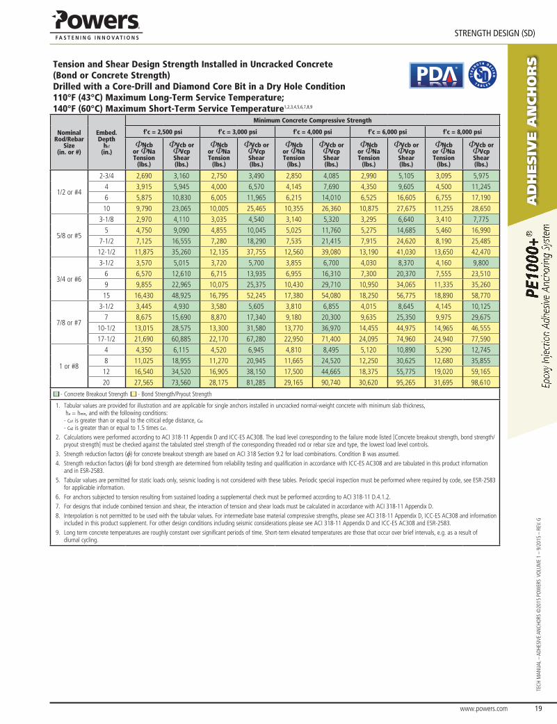
www.powers.com 19
aD
hesiV
e a
nch
or
s
STReNGTH DeSIGN (SD)
TECH
MAN
UAL
– AD
HESI
VE A
NCH
ORS
©20
15 P
OW
ERS
VO
LUM
E 1
– 9/
2015
– R
EV. G
Tension and Shear Design Strength Installed in Uncracked Concrete(Bond or Concrete Strength)Drilled with a Core-Drill and Diamond Core Bit in a Dry Hole Condition110°F (43°C) Maximum Long-Term Service Temperature;140°F (60°C) Maximum Short-Term Service Temperature1,2,3,4,5,6,7,8,9
®
Nominal Rod/Rebar
Size(in. or #)
Embed.Depth
hef
(in.)
Minimum Concrete Compressive Strength
f'c = 2,500 psi f'c = 3,000 psi f'c = 4,000 psi f'c = 6,000 psi f'c = 8,000 psi
ΦNcbor ΦNaTension
(lbs.)
ΦVcb or ΦVcpShear(lbs.)
ΦNcbor ΦNaTension
(lbs.)
ΦVcb or ΦVcpShear(lbs.)
ΦNcbor ΦNaTension
(lbs.)
ΦVcb or ΦVcpShear(lbs.)
ΦNcbor ΦNaTension
(lbs.)
ΦVcb or ΦVcpShear(lbs.)
ΦNcbor ΦNaTension
(lbs.)
ΦVcb or ΦVcpShear(lbs.)
1/2 or #4
2-3/4 2,690 3,160 2,750 3,490 2,850 4,085 2,990 5,105 3,095 5,975
4 3,915 5,945 4,000 6,570 4,145 7,690 4,350 9,605 4,500 11,245
6 5,875 10,830 6,005 11,965 6,215 14,010 6,525 16,605 6,755 17,190
10 9,790 23,065 10,005 25,465 10,355 26,360 10,875 27,675 11,255 28,650
5/8 or #5
3-1/8 2,970 4,110 3,035 4,540 3,140 5,320 3,295 6,640 3,410 7,775
5 4,750 9,090 4,855 10,045 5,025 11,760 5,275 14,685 5,460 16,990
7-1/2 7,125 16,555 7,280 18,290 7,535 21,415 7,915 24,620 8,190 25,485
12-1/2 11,875 35,260 12,135 37,755 12,560 39,080 13,190 41,030 13,650 42,470
3/4 or #6
3-1/2 3,570 5,015 3,720 5,700 3,855 6,700 4,030 8,370 4,160 9,800
6 6,570 12,610 6,715 13,935 6,955 16,310 7,300 20,370 7,555 23,510
9 9,855 22,965 10,075 25,375 10,430 29,710 10,950 34,065 11,335 35,260
15 16,430 48,925 16,795 52,245 17,380 54,080 18,250 56,775 18,890 58,770
7/8 or #7
3-1/2 3,445 4,930 3,580 5,605 3,810 6,855 4,015 8,645 4,145 10,125
7 8,675 15,690 8,870 17,340 9,180 20,300 9,635 25,350 9,975 29,675
10-1/2 13,015 28,575 13,300 31,580 13,770 36,970 14,455 44,975 14,965 46,555
17-1/2 21,690 60,885 22,170 67,280 22,950 71,400 24,095 74,960 24,940 77,590
1 or #8
4 4,350 6,115 4,520 6,945 4,810 8,495 5,120 10,890 5,290 12,745
8 11,025 18,955 11,270 20,945 11,665 24,520 12,250 30,625 12,680 35,855
12 16,540 34,520 16,905 38,150 17,500 44,665 18,375 55,775 19,020 59,165
20 27,565 73,560 28,175 81,285 29,165 90,740 30,620 95,265 31,695 98,610
■ - Concrete Breakout Strength ■ - Bond Strength/Pryout Strength
1. Tabular values are provided for illustration and are applicable for single anchors installed in uncracked normal-weight concrete with minimum slab thickness, ha = hmin, and with the following conditions: - ca1 is greater than or equal to the critical edge distance, cac - ca2 is greater than or equal to 1.5 times ca1.
2. Calculations were performed according to ACI 318-11 Appendix D and ICC-ES AC308. The load level corresponding to the failure mode listed [Concrete breakout strength, bond strength/pryout strength] must be checked against the tabulated steel strength of the corresponding threaded rod or rebar size and type, the lowest load level controls.
3. Strength reduction factors (f) for concrete breakout strength are based on ACI 318 Section 9.2 for load combinations. Condition B was assumed. 4. Strength reduction factors (f) for bond strength are determined from reliability testing and qualification in accordance with ICC-ES AC308 and are tabulated in this product information
and in ESR-2583.5. Tabular values are permitted for static loads only, seismic loading is not considered with these tables. Periodic special inspection must be performed where required by code, see ESR-2583
for applicable information.6. For anchors subjected to tension resulting from sustained loading a supplemental check must be performed according to ACI 318-11 D.4.1.2.7. For designs that include combined tension and shear, the interaction of tension and shear loads must be calculated in accordance with ACI 318-11 Appendix D.8. Interpolation is not permitted to be used with the tabular values. For intermediate base material compressive strengths, please see ACI 318-11 Appendix D, ICC-ES AC308 and information
included in this product supplement. For other design conditions including seismic considerations please see ACI 318-11 Appendix D and ICC-ES AC308 and ESR-2583. 9. Long term concrete temperatures are roughly constant over significant periods of time. Short-term elevated temperatures are those that occur over brief intervals, e.g. as a result of
diurnal cycling.
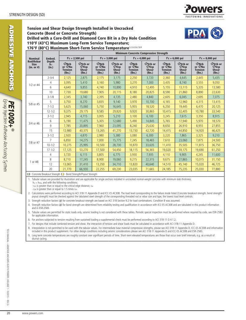
aD
hesiV
e a
nch
or
s
www.powers.com 20
TECH MAN
UAL – ADHESIVE ANCHO
RS ©2015 PO
WERS VO
LUME 1 – 9/2015 – REV. G
STReNGTH DeSIGN (SD)
Tension and Shear Design Strength Installed in Uncracked Concrete (Bond or Concrete Strength)Drilled with a Core-Drill and Diamond Core Bit in a Dry Hole Condition110°F (43°C) Maximum Long-Term Service Temperature; 176°F (80°C) Maximum Short-Term Service Temperature1,2,3,4,5,6,7,8,9
®
Nominal Rod/Rebar
Size(in. or #)
Embed.Depth
hef
(in.)
Minimum Concrete Compressive Strength
f'c = 2,500 psi f'c = 3,000 psi f'c = 4,000 psi f'c = 6,000 psi f'c = 8,000 psi
ΦNcbor ΦNaTension
(lbs.)
ΦVcb or ΦVcpShear(lbs.)
ΦNcbor ΦNaTension
(lbs.)
ΦVcb or ΦVcpShear(lbs.)
ΦNcbor ΦNaTension
(lbs.)
ΦVcb or ΦVcpShear(lbs.)
ΦNcbor ΦNaTension
(lbs.)
ΦVcb or ΦVcpShear(lbs.)
ΦNcbor ΦNaTension
(lbs.)
ΦVcb or ΦVcpShear(lbs.)
1/2 or #4
2-3/4 2,125 2,875 2,175 3,175 2,250 3,720 2,360 4,645 2,445 5,435
4 3,095 5,410 3,160 5,980 3,270 7,000 3,435 8,740 3,555 9,050
6 4,640 9,855 4,740 10,890 4,910 12,495 5,155 13,115 5,335 13,580
10 7,730 19,680 7,905 20,115 8,180 20,825 8,590 21,860 8,890 22,630
5/8 or #5
3-1/8 2,345 3,740 2,395 4,135 2,480 4,840 2,605 6,045 2,695 7,075
5 3,750 8,270 3,835 9,140 3,970 10,700 4,165 12,960 4,315 13,415
7-1/2 5,625 15,060 5,750 16,645 5,955 18,520 6,250 19,445 6,470 20,125
12-1/2 9,375 29,175 9,585 29,820 9,920 30,865 10,415 32,405 10,780 33,540
3/4 or #6
3-1/2 2,945 4,715 3,005 5,210 3,100 6,100 3,245 7,615 3,350 8,915
6 5,190 11,475 5,305 12,680 5,490 14,845 5,765 17,940 5,970 18,570
9 7,785 20,895 7,960 23,095 8,240 25,630 8,650 26,910 8,955 27,855
15 12,980 40,375 13,265 41,270 13,730 42,720 14,415 44,850 14,920 46,425
7/8 or #7
3-1/2 2,920 4,870 2,980 5,380 3,080 6,300 3,220 7,865 3,325 9,210
7 6,850 14,275 7,000 15,775 7,245 18,465 7,610 23,060 7,875 24,500
10-1/2 10,275 25,995 10,500 28,730 10,870 33,635 11,410 35,505 11,815 36,750
17-1/2 17,125 53,270 17,500 54,450 18,115 56,365 19,020 59,175 19,690 61,250
1 or #8
4 3,720 6,115 3,805 6,775 3,930 7,935 4,110 9,905 4,245 11,600
8 8,710 17,245 8,900 19,060 9,215 22,315 9,675 27,865 10,015 31,150
12 13,065 31,410 13,350 34,710 13,820 40,640 14,510 45,140 15,020 46,725
20 21,770 66,930 22,255 69,230 23,035 71,665 24,185 75,235 25,030 77,880
■ - Concrete Breakout Strength ■ - Bond Strength/Pryout Strength
1. Tabular values are provided for illustration and are applicable for single anchors installed in uncracked normal-weight concrete with minimum slab thickness, ha = hmin, and with the following conditions: - ca1 is greater than or equal to the critical edge distance, cac - ca2 is greater than or equal to 1.5 times ca1.
2. Calculations were performed according to ACI 318-11 Appendix D and ICC-ES AC308. The load level corresponding to the failure mode listed [Concrete breakout strength, bond strength/pryout strength] must be checked against the tabulated steel strength of the corresponding threaded rod or rebar size and type, the lowest load level controls.
3. Strength reduction factors (f) for concrete breakout strength are based on ACI 318 Section 9.2 for load combinations. Condition B was assumed. 4. Strength reduction factors (f) for bond strength are determined from reliability testing and qualification in accordance with ICC-ES AC308 and are tabulated in this product information
and in ESR-2583.5. Tabular values are permitted for static loads only, seismic loading is not considered with these tables. Periodic special inspection must be performed where required by code, see ESR-2583
for applicable information.6. For anchors subjected to tension resulting from sustained loading a supplemental check must be performed according to ACI 318-11 D.4.1.2.7. For designs that include combined tension and shear, the interaction of tension and shear loads must be calculated in accordance with ACI 318-11 Appendix D.8. Interpolation is not permitted to be used with the tabular values. For intermediate base material compressive strengths, please see ACI 318-11 Appendix D, ICC-ES AC308 and information
included in this product supplement. For other design conditions including seismic considerations please see ACI 318-11 Appendix D and ICC-ES AC308 and ESR-2583. 9. Long term concrete temperatures are roughly constant over significant periods of time. Short-term elevated temperatures are those that occur over brief intervals, e.g. as a result of
diurnal cycling.
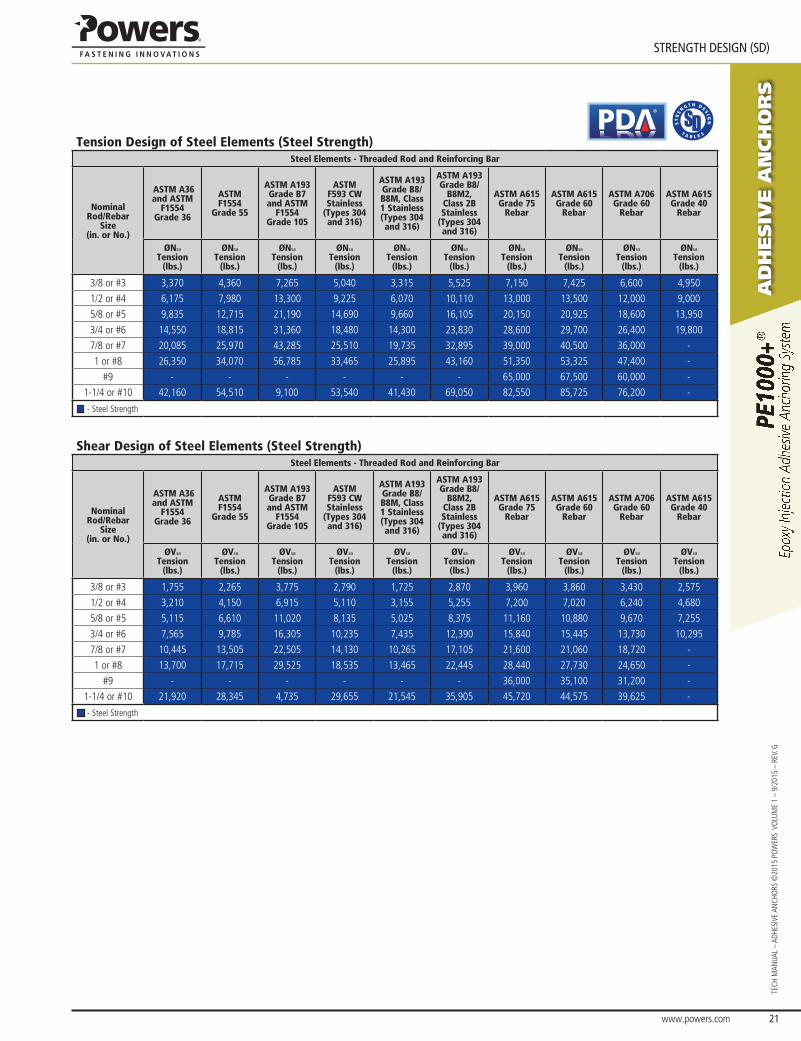
www.powers.com 21
aD
hesiV
e a
nch
or
s
STReNGTH DeSIGN (SD)
TECH
MAN
UAL
– AD
HESI
VE A
NCH
ORS
©20
15 P
OW
ERS
VO
LUM
E 1
– 9/
2015
– R
EV. G
Tension Design of Steel Elements (Steel Strength)
®
Steel Elements - Threaded Rod and Reinforcing Bar
Nominal Rod/Rebar
Size(in. or No.)
ASTM A36 and ASTM
F1554 Grade 36
ASTM F1554
Grade 55
ASTM A193 Grade B7 and ASTM
F1554 Grade 105
ASTM F593 CW Stainless
(Types 304 and 316)
ASTM A193 Grade B8/B8M, Class 1 Stainless (Types 304 and 316)
ASTM A193 Grade B8/
B8M2, Class 2B Stainless
(Types 304 and 316)
ASTM A615 Grade 75
Rebar
ASTM A615 Grade 60
Rebar
ASTM A706 Grade 60
Rebar
ASTM A615 Grade 40
Rebar
ØNsa
Tension(lbs.)
ØNsa
Tension(lbs.)
ØNsa
Tension(lbs.)
ØNsa
Tension(lbs.)
ØNsa
Tension(lbs.)
ØNsa
Tension(lbs.)
ØNsa
Tension(lbs.)
ØNsa
Tension(lbs.)
ØNsa
Tension(lbs.)
ØNsa
Tension(lbs.)
3/8 or #3 3,370 4,360 7,265 5,040 3,315 5,525 7,150 7,425 6,600 4,950
1/2 or #4 6,175 7,980 13,300 9,225 6,070 10,110 13,000 13,500 12,000 9,000
5/8 or #5 9,835 12,715 21,190 14,690 9,660 16,105 20,150 20,925 18,600 13,950
3/4 or #6 14,550 18,815 31,360 18,480 14,300 23,830 28,600 29,700 26,400 19,800
7/8 or #7 20,085 25,970 43,285 25,510 19,735 32,895 39,000 40,500 36,000 -
1 or #8 26,350 34,070 56,785 33,465 25,895 43,160 51,350 53,325 47,400 -
#9 - - - - - - 65,000 67,500 60,000 -
1-1/4 or #10 42,160 54,510 9,100 53,540 41,430 69,050 82,550 85,725 76,200 -
■ - Steel Strength
Shear Design of Steel Elements (Steel Strength)Steel Elements - Threaded Rod and Reinforcing Bar
Nominal Rod/Rebar
Size(in. or No.)
ASTM A36 and ASTM
F1554 Grade 36
ASTM F1554
Grade 55
ASTM A193 Grade B7 and ASTM
F1554 Grade 105
ASTM F593 CW Stainless
(Types 304 and 316)
ASTM A193 Grade B8/B8M, Class 1 Stainless (Types 304 and 316)
ASTM A193 Grade B8/
B8M2, Class 2B Stainless
(Types 304 and 316)
ASTM A615 Grade 75
Rebar
ASTM A615 Grade 60
Rebar
ASTM A706 Grade 60
Rebar
ASTM A615 Grade 40
Rebar
ØVsa
Tension(lbs.)
ØVsa
Tension(lbs.)
ØVsa
Tension(lbs.)
ØVsa
Tension(lbs.)
ØVsa
Tension(lbs.)
ØVsa
Tension(lbs.)
ØVsa
Tension(lbs.)
ØVsa
Tension(lbs.)
ØVsa
Tension(lbs.)
ØVsa
Tension(lbs.)
3/8 or #3 1,755 2,265 3,775 2,790 1,725 2,870 3,960 3,860 3,430 2,575
1/2 or #4 3,210 4,150 6,915 5,110 3,155 5,255 7,200 7,020 6,240 4,680
5/8 or #5 5,115 6,610 11,020 8,135 5,025 8,375 11,160 10,880 9,670 7,255
3/4 or #6 7,565 9,785 16,305 10,235 7,435 12,390 15,840 15,445 13,730 10,295
7/8 or #7 10,445 13,505 22,505 14,130 10,265 17,105 21,600 21,060 18,720 -
1 or #8 13,700 17,715 29,525 18,535 13,465 22,445 28,440 27,730 24,650 -
#9 - - - - - - 36,000 35,100 31,200 -
1-1/4 or #10 21,920 28,345 4,735 29,655 21,545 35,905 45,720 44,575 39,625 -
■ - Steel Strength
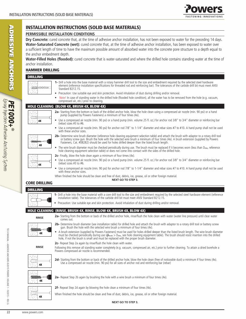
aD
hesiV
e a
nch
or
s
www.powers.com 22
TECH MAN
UAL – ADHESIVE ANCHO
RS ©2015 PO
WERS VO
LUME 1 – 9/2015 – REV. G
INSTALLATIoN INSTRuCTIoNS (SoLID BASe MATeRIALS)
InstallatIon InstructIons (solId base materIals)PerMissiBle insTallaTion condiTionsDry Concrete: cured concrete that, at the time of adhesive anchor installation, has not been exposed to water for the preceding 14 days.Water-Saturated Concrete (wet): cured concrete that, at the time of adhesive anchor installation, has been exposed to water over a sufficient length of time to have the maximum possible amount of absorbed water into the concrete pore structure to a depth equal to the anchor embedment depth.Water-Filled Holes (flooded): cured concrete that is water-saturated and where the drilled hole contains standing water at the time of anchor installation.
hammer drIllIng
DrILLInG1- Drill a hole into the base material with a rotary hammer drill tool to the size and embedment required by the selected steel hardware
element (reference installation specifications for threaded rod and reinforcing bar). The tolerances of the carbide drill bit must meet ANSI Standard B212.15.
• Precaution: Use suitable eye and skin protection. Avoid inhalation of dust during drilling and/or removal.• Note! In case of standing water in the drilled hole (flooded hole condition), all the water has to be removed from the hole (e.g. vacuum,
compressed air, etc.) prior to cleaning.
HoLE CLEAnInG (BLoW 4x, BrUSH 4x, BLoW 4x)
4X
2a- Starting from the bottom or back of the drilled anchor hole, blow the hole clean using a compressed air nozzle (min. 90 psi) or a hand pump (supplied by Powers Fasteners) a minimum of four times (4x).
• Use a compressed air nozzle (min. 90 psi) or a hand pump (min. volume 25 fl. oz.) for anchor rod 3/8" to 3/4" diameter or reinforcing bar (rebar) sizes #3 to #6.
• Use a compressed air nozzle (min. 90 psi) for anchor rod 7/8" to 1-1/4" diameter and rebar sizes #7 to #10. A hand pump shall not be used with these anchor sizes.
4X
2b- Determine wire brush diameter (reference hole cleaning equipment selection table) and attach the brush with adaptor to a rotary drill tool or battery screw gun. Brush the hole with the selected wire brush a minimum of four times (4x). A brush extension (supplied by Powers Fasteners, Cat. #08282) should be used for holes drilled deeper than the listed brush length.
• The wire brush diameter must be checked periodically during use. The brush must be replaced if it becomes worn (less than Dmin, reference hole cleaning equipment selection table) or does not come into contact with the sides of the drilled hole.
4X
2c- Finally, blow the hole clean again a minimum of four times (4x).• Use a compressed air nozzle (min. 90 psi) or a hand pump (min. volume 25 fl. oz.) for anchor rod 3/8" to 3/4" diameter or reinforcing bar
(rebar) sizes #3 to #6.
• Use a compressed air nozzle (min. 90 psi) for anchor rod 7/8" to 1-1/4" diameter and rebar sizes #7 to #10. A hand pump shall not be used with these anchor sizes.
When finished the hole should be clean and free of dust, debris, ice, grease, oil or other foreign material.next go to steP 3.
core drIllIng
DrILLInG1- Drill a hole into the base material with a core drill tool to the size and embedment required by the selected steel hardware element (reference
installation table). The tolerances of the carbide drill bit must meet ANSI Standard B212.15.
• Precaution: Use suitable eye and skin protection. Avoid inhalation of dust during drilling and/or removal.
HoLE CLEAnInG (rInSE, BrUSH 4x, rInSE, BLoW 4x, BrUSH 4x, BLoW 4x)
rinse 2a- Starting from the bottom or back of the drilled anchor hole, rinse/flush the hole clean with water (water line pressure) until clear water comes out.
4X
2b- Determine brush diameter (see installation table) for drilled hole and attach the brush with adaptor to a rotary drill tool or battery screw gun. Brush the hole with the selected wire brush a minimum of four times (4x).
• A brush extension (supplied by Powers Fasteners) must be used for holes drilled deeper than the listed brush length. The wire brush diameter must be checked periodically during use (fbrush > Dmin, see hole cleaning equipment table). The brush should resist insertion into the drilled hole, if not the brush is small and must be replaced with the proper brush diameter.
rinse2c- Repeat Step 2a again by rinse/flush the hole clean with water.Following this remove all standing water completely (e.g. vacuum, compressed air, etc.) prior to further cleaning. To attain a dried borehole a Powers compressed air nozzle is recommended.
4X
2d- Starting from the bottom or back of the drilled anchor hole, blow the hole clean (free of noticeable dust) a minimum if four times (4x). Use a compressed air nozzle (min. 90 psi) for all sizes of anchor rod and reinforcing bar (rebar)
4X2e- Repeat Step 2b again by brushing the hole with a wire brush a minimum of four times (4x).
4X
2f- Repeat Step 2d again by blowing the hole clean a minimum of four times (4x).
When finished the hole should be clean and free of dust, debris, ice, grease, oil or other foreign material.
next go to steP 3.
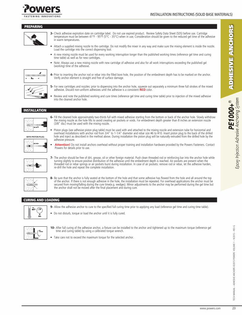
www.powers.com 23
aD
hesiV
e a
nch
or
s
INSTALLATIoN INSTRuCTIoNS (SoLID BASe MATeRIALS)
TECH
MAN
UAL
– AD
HESI
VE A
NCH
ORS
©20
15 P
OW
ERS
VO
LUM
E 1
– 9/
2015
– R
EV. G
prEpArInG
3- Check adhesive expiration date on cartridge label. Do not use expired product. Review Safety Data Sheet (SDS) before use. Cartridge temperature must be between 41°F - 95°F (5°C - 35°C) when in use; Consideration should be given to the reduced gel time of the adhesive in warm temperatures.
• Attach a supplied mixing nozzle to the cartridge. Do not modify the mixer in any way and make sure the mixing element is inside the nozzle. Load the cartridge into the correct dispensing tool.
• A new mixing nozzle must be used for every working interruption longer than the published working times (reference gel time and curing time table) as well as for new cartridges.
• Note: Always use a new mixing nozzle with new cartridge of adhesive and also for all work interruptions exceeding the published gel (working) time of the adhesive.
hef
4- Prior to inserting the anchor rod or rebar into the filled bore hole, the position of the embedment depth has to be marked on the anchor. Verify anchor element is straight and free of surface damage.
3X
5- For new cartridges and nozzles: prior to dispensing into the anchor hole, squeeze out separately a minimum three full strokes of the mixed adhesive. Discard non-uniform adhesives until the adhesive is a consistent red color.
• Review and note the published working and cure times (reference gel time and curing time table) prior to injection of the mixed adhesive into the cleaned anchor hole.
InSTALLATIon
6- Fill the cleaned hole approximately two-thirds full with mixed adhesive starting from the bottom or back of the anchor hole. Slowly withdraw the mixing nozzle as the hole fills to avoid creating air pockets or voids. For embedment depth greater than 8 inches an extension nozzle (3/8" dia.) must be used with the mixing nozzle.
• Piston plugs (see adhesive piston plug table) must be used with and attached to the mixing nozzle and extension tube for horizontal and overhead installations with anchor rod from 3/4" to 1-1/4" diameter and rebar size #6 to #10. Insert piston plug to the back of the drilled hole and inject as described in the method above. During installation the piston plug will be naturally extruded from the drilled hole by the adhesive pressure.
• attention! Do not install anchors overhead without proper training and installation hardware provided by the Powers Fasteners. Contact Powers for details prior to use.
with Piston Plug:
7- The anchor should be free of dirt, grease, oil or other foreign material. Push clean threaded rod or reinforcing bar into the anchor hole while turning slightly to ensure positive distribution of the adhesive until the embedment depth is reached. Air pockets are present when the threaded rod or rebar springs or air pockets burst during installation. In case of air pockets: remove rod or rebar, let the adhesive harden, re-drill the hole and repeat the complete installation.
8- Be sure that the anchor is fully seated at the bottom of the hole and that some adhesive has flowed from the hole and all around the top of the anchor. If there is not enough adhesive in the hole, the installation must be repeated. For overhead applications the anchor must be secured from moving/falling during the cure time(e.g. wedges). Minor adjustments to the anchor may be performed during the gel time but the anchor shall not be moved after the final placement and during cure.
CUrInG AnD LoADInG
e.g.
68˚F
8hrs
9- Allow the adhesive anchor to cure to the specified full curing time prior to applying any load (reference gel time and curing time table).
• Do not disturb, torque or load the anchor until it is fully cured.
Tmax
10- After full curing of the adhesive anchor, a fixture can be installed to the anchor and tightened up to the maximum torque (reference gel time and curing table) by using a calibrated torque wrench.
• Take care not to exceed the maximum torque for the selected anchor.
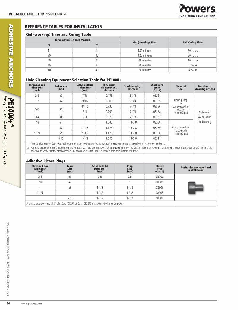
aD
hesiV
e a
nch
or
s
www.powers.com 24
TECH MAN
UAL – ADHESIVE ANCHO
RS ©2015 PO
WERS VO
LUME 1 – 9/2015 – REV. G
ReFeReNCe TABLeS FoR INSTALLATIoN
reFerence tables For InstallatIon
Gel (working) Time and Curing TableTemperature of Base Material
Gel (working) Time Full Curing Time˚F ˚C
41 5 180 minutes 50 hours
50 10 120 minutes 30 hours
68 20 30 minutes 10 hours
86 30 20 minutes 6 hours
104 40 20 minutes 4 hours
Hole Cleaning Equipment Selection Table for PE1000+Threaded rod
diameter (inch)
Rebar size (no.)
ANSI drill bit diameter
(inch)
Min. brush diameter, Dmin
(inches)
Brush length, L(inches)
Steel wire brush
(Cat. #)
Blowout tool
Number of cleaning actions
3/8 #3 7/16 0.475 6-3/4 08284Hand-pump
or compressed air
nozzle (min. 90 psi) 4x blowing
4x brushing
4x blowing
1/2 #4 9/16 0.600 6-3/4 08285
5/8 #511/16 0.735 7-7/8 08286
3/4 0.790 7-7/8 08278
3/4 #6 7/8 0.920 7-7/8 08287
7/8 #7 1 1.045 11-7/8 08288
Compressed airnozzle only
(min. 90 psi)
1 #8 1-1/8 1.175 11-7/8 08289
1-1/4 #9 1-3/8 1.425 11-7/8 08290
- #10 1-1/2 1.550 11-7/8 08291
1. An SDS-plus adaptor (Cat. #08283) or Jacobs chuck style adaptor (Cat. #08296) is required to attach a steel wire brush to the drill tool.2. For installations with 5/8 threaded rod and #5 rebar size, the preferred ANSI drill bit diameter is 3/4-inch. If an 11/16-inch ANSI drill bit is used the user must check before injecting the
adhesive to verify that the steel anchor element can be inserted into the cleaned bore hole without resistance.
Adhesive Piston PlugsThreaded Rod
Diameter(inch)
RebarSize(no.)
ANSI Drill BitDiameter
(inch)
PlugSize
(inch)
PlasticPlug
(Cat. #)
Horizontal and overheadinstallations
3/4 #6 7/8 7/8 08300
7/8 #7 1 1 08301
1 #8 1-1/8 1-1/8 08303
1-1/4 - 1-3/8 1-3/8 08305
- #10 1-1/2 1-1/2 08309
A plastic extension tube (3/8" dia., Cat. #08291 or Cat. #08297) must be used with piston plugs.
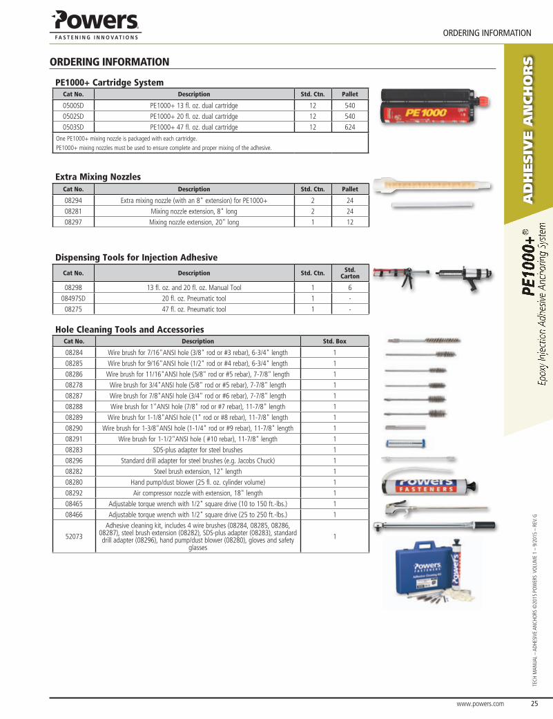
www.powers.com 25
aD
hesiV
e a
nch
or
s
oRDeRING INFoRMATIoN
TECH
MAN
UAL
– AD
HESI
VE A
NCH
ORS
©20
15 P
OW
ERS
VO
LUM
E 1
– 9/
2015
– R
EV. G
orderIng InFormatIon
PE1000+ Cartridge SystemCat No. Description Std. Ctn. Pallet
0500SD PE1000+ 13 fl. oz. dual cartridge 12 540
0502SD PE1000+ 20 fl. oz. dual cartridge 12 540
0503SD PE1000+ 47 fl. oz. dual cartridge 12 624
One PE1000+ mixing nozzle is packaged with each cartridge.PE1000+ mixing nozzles must be used to ensure complete and proper mixing of the adhesive.
Extra Mixing NozzlesCat No. Description Std. Ctn. Pallet
08294 Extra mixing nozzle (with an 8" extension) for PE1000+ 2 24
08281 Mixing nozzle extension, 8" long 2 24
08297 Mixing nozzle extension, 20" long 1 12
Dispensing Tools for Injection Adhesive
Cat No. Description Std. Ctn. Std. Carton
08298 13 fl. oz. and 20 fl. oz. Manual Tool 1 6
08497SD 20 fl. oz. Pneumatic tool 1 -
08275 47 fl. oz. Pneumatic tool 1 -
Hole Cleaning Tools and AccessoriesCat No. Description Std. Box
08284 Wire brush for 7/16"ANSI hole (3/8" rod or #3 rebar), 6-3/4" length 1
08285 Wire brush for 9/16"ANSI hole (1/2" rod or #4 rebar), 6-3/4" length 1
08286 Wire brush for 11/16"ANSI hole (5/8" rod or #5 rebar), 7-7/8" length 1
08278 Wire brush for 3/4"ANSI hole (5/8" rod or #5 rebar), 7-7/8" length 1
08287 Wire brush for 7/8"ANSI hole (3/4" rod or #6 rebar), 7-7/8" length 1
08288 Wire brush for 1"ANSI hole (7/8" rod or #7 rebar), 11-7/8" length 1
08289 Wire brush for 1-1/8"ANSI hole (1" rod or #8 rebar), 11-7/8" length 1
08290 Wire brush for 1-3/8"ANSI hole (1-1/4" rod or #9 rebar), 11-7/8" length 1
08291 Wire brush for 1-1/2"ANSI hole ( #10 rebar), 11-7/8" length 1
08283 SDS-plus adapter for steel brushes 1
08296 Standard drill adapter for steel brushes (e.g. Jacobs Chuck) 1
08282 Steel brush extension, 12" length 1
08280 Hand pump/dust blower (25 fl. oz. cylinder volume) 1
08292 Air compressor nozzle with extension, 18" length 1
08465 Adjustable torque wrench with 1/2" square drive (10 to 150 ft.-lbs.) 1
08466 Adjustable torque wrench with 1/2" square drive (25 to 250 ft.-lbs.) 1
52073
Adhesive cleaning kit, includes 4 wire brushes (08284, 08285, 08286, 08287), steel brush extension (08282), SDS-plus adapter (08283), standard drill adapter (08296), hand pump/dust blower (08280), gloves and safety
glasses
1