Embed Size (px)
Citation preview
GENERAL INSTRUCTIONS – NEW FULL SIZE C/K PICKUPS & CHASSIS-CABS PA
GE
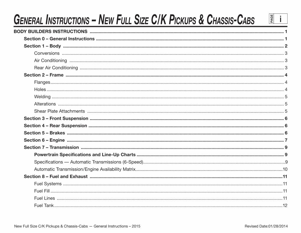
iBODY BUILDERS INSTRUCTIONS ......................................................................................................................................................... 1
Section 0 – General Instructions .................................................................................................................................................... 1
Section 1 – Body .............................................................................................................................................................................. 2
Conversions ............................................................................................................................................................................... 3
Air Conditioning ......................................................................................................................................................................... 3
Rear Air Conditioning ................................................................................................................................................................. 3
Section 2 – Frame ............................................................................................................................................................................ 4
Flanges ........................................................................................................................................................................................ 4
Holes ........................................................................................................................................................................................... 4
Welding ....................................................................................................................................................................................... 5
Alterations .................................................................................................................................................................................. 5
Shear Plate Attachments ........................................................................................................................................................... 5
Section 3 – Front Suspension ......................................................................................................................................................... 6
Section 4 – Rear Suspension .......................................................................................................................................................... 6
Section 5 – Brakes ........................................................................................................................................................................... 6
Section 6 – Engine ........................................................................................................................................................................... 7
Section 7 – Transmission ................................................................................................................................................................ 9
Powertrain Specifications and Line-Up Charts .................................................................................................................... 9
Specifications — Automatic Transmissions (6-Speed) ................................................................................................................9
Automatic Transmission/Engine Availability Matrix....................................................................................................................10
Section 8 – Fuel and Exhaust ........................................................................................................................................................11
Fuel Systems .............................................................................................................................................................................11
Fuel Fill .......................................................................................................................................................................................11
Fuel Lines ..................................................................................................................................................................................11
Fuel Tank ....................................................................................................................................................................................12
Revised Date:01/28/2014New Full Size C/K Pickups & Chassis-Cabs — General Instructions – 2015
General InstructIons – new Full sIze c/K PIcKuPs & chassIs-cabs PA
GE
��General InstructIons – new Full sIze c/K PIcKuPs & chassIs-cabs PA
GE
��BODY BUILDERS INSTRUCTIONS – Continued
Gaseous Fuel Conversions .......................................................................................................................................................12
Exhaust System ........................................................................................................................................................................13
2007I Diesel Exhaust Systems, option LMM, Duramax 6.6L Diesel ........................................................................................14
Sect�on 9 – Steer�ng ....................................................................................................................................................................... 15
Sect�on 10 – T�res ........................................................................................................................................................................... 15
Sect�on 12 – Electr�cal Battery and Battery Cables ................................................................................................................... 16
Auxiliary Battery (Heavy Duty Pickups, Gasoline Engines Only) ..............................................................................................16
Sect�on 13 – Cool�ng .......................................................................................................................................................................17
Revised Date:01/28/2014New Full Size C/K Pickups & Chassis-Cabs — General Instructions – 2015
GENERAL INSTRUCTIONS – NEW FULL SIZE C/K PICKUPS & CHASSIS-CABS PA
GE
1BODY BUILDERS INSTRUCTIONS
The Incomplete Vehicle Document (IVD) is supplied with each incomplete vehicle, and provides information that should be used by intermediate and final stage manufacturers in determining conformity to applicable Federal Motor Vehicle Safety Standards (FMVSS). The IVD also includes information which must be followed in order to ensure that Environmental Protection Agency (EPA) and California emissions certification requirements and NHTSA Fuel Regulations are met.
This Body Builders Book contains information that may be used in addition to the IVD for any manufacturer making alterations to a GM complete/incomplete vehicle. No alteration should be made to the incomplete vehicle which either directly or indirectly results in any component, assembly or system being in nonconformance with any applicable Federal Motor Vehicle Safety Standard or Emission Regulation. Intermediate and final stage manufacturers should be familiar with all Federal Motor Vehicle Safety Standards and Emission Regulations and aware of their specific responsibilities as manufacturers.
For further assistance contact Upfitter Integration at: 1 (800) 875-4742, or go to our Web site at “http://www.gmupfitter.com.”
Section 0 — General InstructionsCheck for proper clearance between body members and chassis components which may in anyway affect the reliability and performance of the vehicle by developing abrasion and wear points from moving parts or degradation from extreme environment or thermal exposure or may increase interior noise.
Check headlamp aim and all vehicle illumination systems for proper operation when the vehicle has been completed. Re-aim headlamps when necessary. Check for proper operation of windshield washer, wipers and defroster system.
Extreme care must be taken when working on vehicles equipped with Engine Control Module (ECM), Transmission Control Module (TCM), Power Take Off Control Module (PTOCM), Integrated Trailer Brake Controller (ITBC) or any electronic unit associated with an inflatable restraint system. (See Owner’s Manual).
If arc-welding is employed on the chassis, precautions must be taken to protect all vehicle components, especially brake and fuel lines, fuel tank assembly, electrical wiring and ECM/TCM/PTOCM or ITBC. To avoid electronic component damage, disconnect battery (batteries); disconnect the negative cable first, followed by the positive. To reconnect cables; connect the positive first, then the negative.
When welding components to the frame assembly, remove the wax coating in the area of the weld in order to obtain secure welds. After completion of the weld, a compatible corrosion protection should be applied to the affected weld areas.
Revised Date:01/28/2014New Full Size C/K Pickups & Chassis-Cabs — General Instructions – 2015

GENERAL INSTRUCTIONS – NEW FULL SIZE C/K PICKUPS & CHASSIS-CABS PA
GE
2(Section 0 — continued from previous page)
All labels on the vehicle (any message applied to the vehicle or vehicle component that informs, instructs, or warns) must appear on the completed vehicle so the user can read them easily and without obstruction.
Those installing aftermarket systems should provide information as to where and how to obtain service and replacement parts.
When installing a Power Take-Off (PTO) with hydraulic lines, the following care should be exercised:
• Route and secure all hydraulic lines so that they are not in close proximity to any parts of the exhaust system. Keep all fittings and connections away from the exhaust system. Make sure connections and fittings cannot leak on the exhaust system.
• Exhaust system heat can damage and degrade hydraulic lines and components. Oils and hydraulic fluid coming in contact with a hot exhaust system could result in a fire.
Section 1 — BodyAccessory items, such as refrigerator, hot water heater, furnace, etc., which operate on liquid propane gas should be located and protected to prevent exposure to any flame.
GM has established automotive refinishing standards for itself as well as its aftermarket retailers. Each division requires the dealer or retailer to use only materials and methods that meet GM standard GM 4901M when repairing, replacing or refinishing vehicles.
Each year, all new paint systems will be tested and evaluated. New or improved products will also be tested. The paint systems that pass this annual testing process will be published in this booklet, and updated annually.
If GM 4901M booklets are needed, call 1-800-269-5100.
Body structures, interior and accessory arrangements must be designed into the vehicle to provide for proper load distribution on both axles and not to exceed any gross axle weight ratings. Lateral load equalization must also be maintained. The resultant Center of Gravity of the unladen vehicle must be within the limits tabulated in the FMVSS 105 section of the Incomplete Vehicle Document.
Body insulation provided by General Motors should not be removed. This includes any thermal or underbody heat shields. This insulation is provided to protect the vehicle body and occupants from excessive heat and/or provide noise attenuation. Any replacement material internal to the occupant compartment must be certified for FMVSS 302 Flammability of Interior Materials. Areas of specific concern, but not limited to are:
• Underbody exhaust, muffler and tail pipe shields and insulators.
Revised Date:01/28/2014New Full Size C/K Pickups & Chassis-Cabs — General Instructions – 2015
GENERAL INSTRUCTIONS – NEW FULL SIZE C/K PICKUPS & CHASSIS-CABS PA
GE
3(Section 1 — continued from previous page)
• Rear load floor interior insulation.
• Front floor interior insulation.
• Dash mat insulation.
• Engine cowl insulation – interior and exterior.
• Engine cover insulation.
• Hood Insulation
Conversions
A minimum of 10º departure angle should be maintained if frame and/or body is extended.
Selected trim components above the belt line have energy absorbing foam added behind the trim (headliners, A, B and C garnish moldings), to comply with MVSS 201. Any modification could affect compliance.
If body builder installs seating other than that supplied with vehicle, it is the body builder’s responsibility to ensure that the seating and restraint systems comply with FMVSS requirements. The restraint systems supplied with the vehicle were designed to accommodate the seating reference points and seat travel of the original equipment seats only.
Air Conditioning
For additional information refer to Engine - Section 6.
NOTE: Air conditioning systems using R-134A refrigerant are equipped with metric fittings to prevent interchange with R-12 refrigerant components. Do not interchange R-134A components, refrigerant oil or service equipment with R-12 components, refrigerant oil or service equipment.
Rear Air Conditioning
This unit is equipped with A/C Swagelok® fittings (Option YF7) on the liquid tube (high pressure) and the suction (low pressure) return tube. These fittings are designed to accept matching threaded fittings. The connection of a rear A/C system requires a discharge, evacuation and recharge of the A/C system.
New Full Size C/K Pickups & Chassis-Cabs — General Instructions – 2014 Revised Date:01/28/2014New Full Size C/K Pickups & Chassis-Cabs — General Instructions – 2015
GENERAL INSTRUCTIONS – NEW FULL SIZE C/K PICKUPS & CHASSIS-CABS PA
GE
4(Section 1 — continued from previous page)
A modification to the A/C system which causes the A/C plumbing lines to increase in length (such as the addition of a rear after-market evaporator and blower assembly) will necessitate the following changes:
• Lubrication – PAG refrigerant oil must be added to rear system to provide lubrication for compressor. Refer to Service Manual for specifications.
• Refrigerant – Add R-134A refrigerant to system based on sizing of new tubes, hoses and evaporator. Contact your A/C supplier for recommended charge.
• Label – Revise/modify GM charge label (located on upper air baffle on top of radiator support) from factory recommended charge for a front system only to body builder’s new recommended dual system per SAE J639. This is important for servicing the A/C system so that the technician knows the correct amount to add to the modified system.
Section 2 — FrameHole drilling, welding, modifications, or alterations to the frame assembly are the responsibility of persons performing these operations. These same individuals assume complete responsibility for frame assembly, reliability, performance after alterations and compliance to applicable FMVSS requirements.
The following procedures and specific precautionary instructions are recommended for proper installation of special bodies and/or equipment on GM frames. Failure to follow these recommendations could result in serious damage to the basic vehicle.
Flanges
Do not drill holes in frame flanges.
Holes
Holes to mount brackets, supports, and out-riggers must be drilled in the vertical side rail web with the following restrictions:
• Material between edge of hole and inside of upper or lower flange must not be less than 37 mm (1.50 in.) for HSLA
• The minimum edge distance between any two (2) holes must be larger than twice the diameter of the larger hole.
• No holes should exceed 20 mm (0.75 in.) in diameter.
• All holes should be drilled in the frame using appropriate drilling practice and safety precautions.
Revised Date:01/28/2014New Full Size C/K Pickups & Chassis-Cabs — General Instructions – 2015
GENERAL INSTRUCTIONS – NEW FULL SIZE C/K PICKUPS & CHASSIS-CABS PA
GE
5(Section 2 — continued from previous page)
Welding
CAUTION: Fuel tank and fuel lines must be drained and all vapors purged to ensure non-combustible mixture before any welding, brazing or soldering.
When welding high-strength, low-allow (HSLA) side rails or crossmembers and brackets, emphasis is placed upon weld application techniques to avoid stress risers that may adversely affect frame operating stresses.
When welding is performed anywhere on the vehicle, precautionary measures should be taken to prevent damage to electrical system wiring or components. Prior to any welding, parts or components which could be damaged by excessive temperatures must be removed or adequately shielded; the battery cables should be disconnected at the battery. Also prior to welding, the area to be welded and surrounding area must be cleaned of all frame protective coating. After welding, when parts are cool, carefully inspect wiring and electrical components for shorts or other damage which could draw excessive currents and possibly cause an electrical system short when the battery is reconnected. Apply protective coating to areas where coating was removed.
Alterations
If the wheelbase is modified the alterer must take responsibility for compliance with affected FMVSS and for warranty on items such as driveshafts, universal joints, center bearings and rear transmission tailshaft, transfercase and transmission case fractures, output shaft bushings, bearings, brakes, fuel systems and any other related component failures. Additionally, the customer must be alerted in the modifier’s owner’s manual that parts for the reworked area are not available through the General Motors service parts system.
Shear Plate Attachments
Attachments of shear plates should be accomplished by using existing manufacturing holes already available in the frame side rails. no bew eht fo retnec eht ni rebmem edis emarf eht gnola decalp yltnetsisnoc era ,retemaid ni mm 52 yllamron ,seloh gnirutcafunaM
each frame.
When additional holes are required for shear plate attachment, they should be no larger than 19 mm (0.75 in.) in diameter. Holes are to be drilled no closer than 63.5 mm (2.5 in.) apart. For holes drilled forward of the rear axle, centers are to be no closer than 63.5 mm (2.5 in.) from the top or bottom flanges and no closer than 89 mm (3.5 in.) from any suspension attachments. For frame holes drilled rearward of the rear axle, hole centers are to be no closer than 51 mm (2.0 in.) from the top or bottom flange and no closer than 89 mm (3.5 in.) from suspension attachments.
No additional holes or notching of either top or bottom frame flanges is allowed.
Revised Date:01/28/2014New Full Size C/K Pickups & Chassis-Cabs — General Instructions – 2015
GENERAL INSTRUCTIONS – NEW FULL SIZE C/K PICKUPS & CHASSIS-CABS PA
GE
6Section 3 — Front Suspension
Since there is a large variation in completed vehicle front weight due to differences in body weight and equipment, the front suspension alignment must be checked and reset if necessary after the vehicle is completed. Caster and camber should be set with reference to the “A” dimensions.
See Truck Service Manual for complete alignment procedure, specifications and measurement of the “A” dimension under “Diagnosis and Front Alignment” section.
C/K Models are designed such that camber and caster do not need adjustment unless severe road impact or accident deformation occurs. Toe should be reset after the vehicle is completed and while at normal operating load with trim height as specified (K-Model).
Section 4 — Rear SuspensionClearance to body should be provided for the suspension, axle, driveshaft and tires under the following conditions: (1) Axle in full jounce against the metal-to-metal stop, (2) Axle at 4.5º roll with one side of axle in full jounce at the metal-to-metal stop and (3) Axle at design position. Allowance for the tire chain clearance shown on a maximum grown tire must allow for 42.2 mm (1.66 in.) clearance to the sides of the tire and 63.5 mm (2.5 in.) to the top of the tire. Be sure sufficient clearance is provided for suspension, axle and tire and wheel in full vertical travel (up and down).
NOTE: Notification to the consumer may be required in certain states if tire chains cannot be used.
Pipes, wiring, conduits and any other related components must not be placed where they cross the path of motion of the rear axle, driveshaft, axle brake pipes, hoses, spring or tires. Such crossing could result in rupture, wear-through, or separation due to normal axle motion.
See chassis data information for additional clearances and for assistance in calculating trim heights.
Section 5 — BrakesSee Truck Service Manual for brake specifications.
Due to the critical nature of brake systems, anyone making modifications or alterations must assume complete responsibility for system reliability, performance and certification to FMVSS 105 or FMVSS 121.
New Full Size C/K Pickups & Chassis-Cabs — General Instructions – 2014 Revised Date:01/28/2014New Full Size C/K Pickups & Chassis-Cabs — General Instructions – 2015
GENERAL INSTRUCTIONS – NEW FULL SIZE C/K PICKUPS & CHASSIS-CABS PA
GE
7(Section 5 — continued from previous page)
It is mandatory that no change be made to the brake main cylinder location, brake pedal push rod length or pedal position. Ensure that the hydraulic brake system is free of air and hydraulic leaks. Bleed brakes if required, following procedures as outlined in truck chassis service manual. Ensure that the vacuum booster system or hydraulic brake booster system is functional and free of leaks.
Check master cylinder fluid level and fill as necessary. (Refer to Owner’s Manual).
Check power steering fluid level for models equipped with hydroboost brake. (Refer to Owner’s Manual).
Added floor covering or carpeting must not restrict service or parking brake pedal travel from released position to full pedal travel.
No body part or chassis-mounted component may be located within 2.0 in. of brake hose routing in all wheel and axle positions. All exhaust system components must also have a minimum of 2.0 in. clearance to brake hoses in closest positions. (Be sure to account for brake hose travel with suspension.)
Body builder is to verify that the brake warning switch is operative. The brake warning switch on models equipped with vacuum-hydraulic brakes is located on the master cylinder. This includes both the brake system fluid level and parking brake actuator switch.
Section 6 — EngineFor additional information refer to Body - Section 1.
Air conditioning and auxiliary belt-driven equipment installation recommendations:
No alterations or additions to the accessory drive belt system will be warranted on serpentine belt systems.
The serpentine belt type of drive is designed as a total system, incorporating a single poly-V belt and an automatic tensioner. In this type of system, degrees of pulley wrap, belt tension, and pulley alignment are very critical factors. Modification is not recommended.
In some single belt serpentine systems, belt tension is determined by the automatic tensioner and its position relative to the belt. No adjustment required.
Due to the critical nature of the accelerator system, anyone making modifications or alterations assumes complete responsibility for system reliability, performance and compliance to FMVSS 124.
Revised Date:01/28/2014New Full Size C/K Pickups & Chassis-Cabs — General Instructions – 2015
GENERAL INSTRUCTIONS – NEW FULL SIZE C/K PICKUPS & CHASSIS-CABS PA
GE
8(Section 6 — continued from previous page)
• Caution must be taken so that the accelerator pedal remains properly located. Guidelines for accelerator pedal locations are as follows:
1) Ensure that the accelerator can freely operate from idle to wide-open throttle position and return. Make sure that the pedal will not hang up on any nearby items such as carpets, floor, screws, wiring harnesses, etc.
2) Accelerator to brake pedal relationship has been designed to provide minimum driver movement and should not be altered in any way.
Gasoline engine induction and/or ignition system is certified in compliance with the Federal Vehicle Emission Standards. Any alterations to the systems or components could void compliance and render the vehicle illegal. System includes:
• Fuel system – throttle body fuel rails and associated tubes, hoses and pipes, air cleaner, outside air hose and spacer heat stove and heat stove pipe, fuel pump and inlet manifold, fuel vapor canister.
• Exhaust system.
• Ignition system dis and coil packs, spark plugs, spark plug wires.
• Crankcase ventilation system.
Diesel engine induction and injector pump system is certified to be in compliance with the Federal Vehicle Emission Standards and/or Noise Standards. Any alterations to the system or components could void compliance and render the vehicle illegal. System includes:
• Fuel system – Injection pump, injector lines and injectors, fuel return hoses and pipes, air cleaner, outside air hose, fuel pump, fuel filter, fuel heater assembly and intake manifold.
• Exhaust system.
• Crankcase pressure regulation system.
• Charge air cooler system.
• Engine driven fan clutch – electronically controlled.
• External engine components, such as air cleaner, crankcase pressure regulator valve, alternator, injection pipes, fuel return hoses from injectors, exhaust manifolds, oil fill pipe, etc., must be provided with sufficient clearance for engine roll and torque.
• When a vehicle is equipped with a electronic fuel injection (EFI) engine, it has an engine control module ECM/TCM/PTOCM or ITBC. This ECM/TCM/PTOCM or ITBC must be maintained at a temperature below 185ºF at all times. This is most essential if the vehicle is put through a paint baking process. The ECM/TCM/PTOCM or ITBC will become inoperative if its temperature exceeds 185ºF. Therefore, it is recommended that temporary insulation be placed around the ECM/TCM/PTOCM or ITBC during the time the vehicle is in a paint oven or undergoing another high temperature process.
Revised Date:01/28/2014New Full Size C/K Pickups & Chassis-Cabs — General Instructions – 2015
GENERAL INSTRUCTIONS – NEW FULL SIZE C/K PICKUPS & CHASSIS-CABS PA
GE
9Section 7 — Transmission
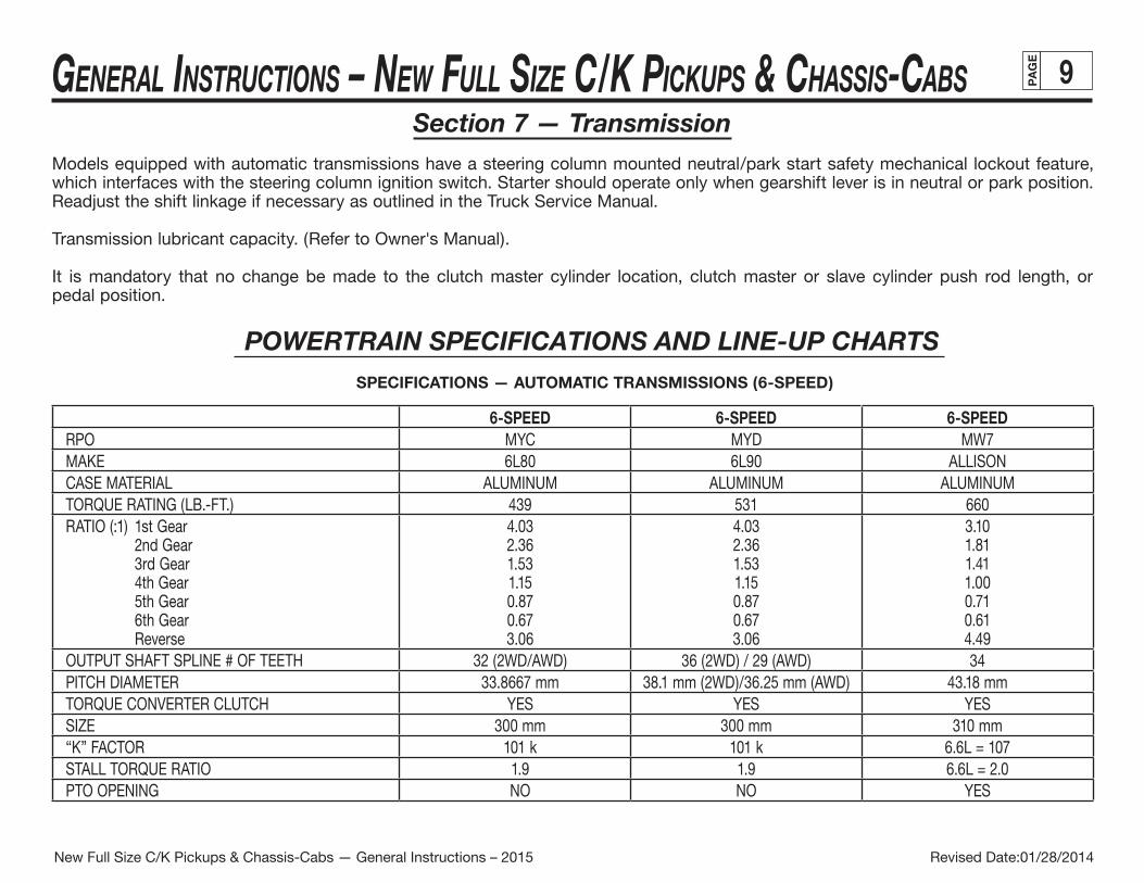
Models equipped with automatic transmissions have a steering column mounted neutral/park start safety mechanical lockout feature, which interfaces with the steering column ignition switch. Starter should operate only when gearshift lever is in neutral or park position. Readjust the shift linkage if necessary as outlined in the Truck Service Manual.
Transmission lubricant capacity. (Refer to Owner's Manual).
It is mandatory that no change be made to the clutch master cylinder location, clutch master or slave cylinder push rod length, or pedal position.
SPECIFICATIONS — AUTOMATIC TRANSMISSIONS (6-SPEED)
6-SPEED 6-SPEED 6-SPEEDRPO MYC MYD MW7MAKE 6L80 6L90 ALLISONCASE MATERIAL ALUMINUM ALUMINUM ALUMINUMTORQUE RATING (LB.-FT.) 439 531 660
raeG ts1 )1:( OITAR2nd Gear 3rd Gear 4th Gear 5th Gear 6th Gear Reverse
4.03 2.36 1.53 1.15 0.87 0.67 3.06
4.03 2.36 1.53 1.15 0.87 0.67 3.06
3.10 1.81 1.41 1.00 0.71 0.61 4.49
OUTPUT SHAFT SPLINE # OF TEETH 32 (2WD/AWD) 36 (2WD) / 29 (AWD) 34PITCH DIAMETER 33.8667 mm 38.1 mm (2WD)/36.25 mm (AWD) 43.18 mmTORQUE CONVERTER CLUTCH YES YES YESSIZE 300 mm 300 mm 310 mm“K” FACTOR 101 k 101 k 6.6L = 107STALL TORQUE RATIO 1.9 1.9 6.6L = 2.0PTO OPENING NO NO YES
POWERTRAIN SPECIFICATIONS AND LINE-UP CHARTS
Revised Date:01/28/2014New Full Size C/K Pickups & Chassis-Cabs — General Instructions – 2015
GENERAL INSTRUCTIONS – NEW FULL SIZE C/K PICKUPS & CHASSIS-CABS PA
GE
10(Section 7 — continued from previous page)
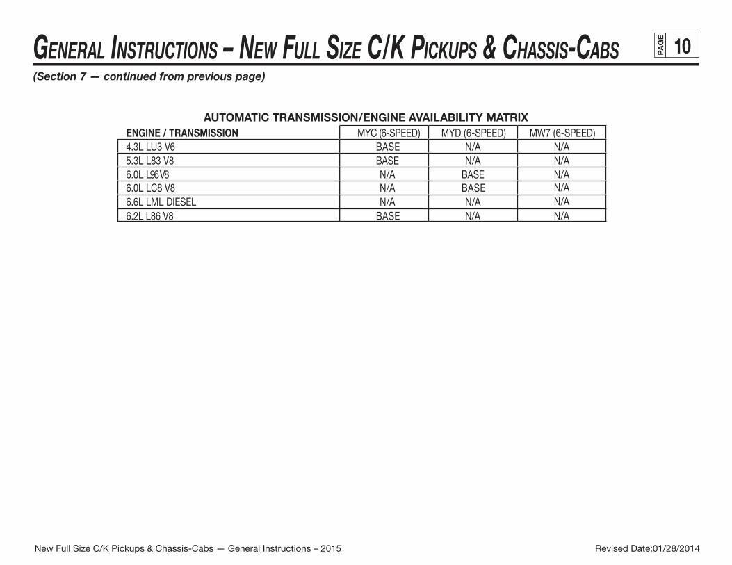
AUTOMATIC TRANSMISSION/ENGINE AVAILABILITY MATRIXENGINE / TRANSMISSION MYC (6-SPEED) MYD (6-SPEED) MW7 (6-SPEED)4.3L LU3 V6 BASE N/A N/A5.3L L83 V8 N/A N/A
N/A BASE N/A
N/A6.6L LML DIESEL N/A N/AN/A6.0L LC8 V8 N/A BASE
6.0L L96 V8
6.2L L86 V8 BASE N/A N/A
BASE
Revised Date:01/28/2014New Full Size C/K Pickups & Chassis-Cabs — General Instructions – 2015

GENERAL INSTRUCTIONS – NEW FULL SIZE C/K PICKUPS & CHASSIS-CABS PA
GE
11Section 8 — Fuel and Exhaust
Fuel Systems
The fuel evaporative emission control equipment is certified to be in compliance with the Federal and California Vehicle Emission Standards. The fuel tank is molded from multi-layer plastic and should not be repaired or altered. Metal fuel lines have a surface coating to reduce corrosion on inside and outside surfaces to comply with useful life requirements. All fuel hoses, including plastic lines, are made of a low permeation multi-layer material to comply with enhanced evaporative emission requirements. Any alterations to systems or components including materials, hose lengths and their location, except as described in the fuel fill system modifications section, could void compliance. The system includes:
• Fuel tank, fuel level sender, fuel fill and vent hoses and pipes, emission canisters, fuel feed, fuel return and vapor lines, purge control solenoids, fuel fill cap, canister vent solenoid.
For these reasons, NO ALTERATION OF THE FUEL SYSTEM IS RECOMMENDED.
Fuel Fill
It is recommended that when mounting the fuel filler pipe assembly and vent hose that a minimum of 3.0 in. clearance be provided to any body component to prevent contact between hoses and/or mating parts and that retention be provided to ensure routing and prevent failure due to wear and fatigue. Both the fill and vent hoses must be routed (and supported, if needed) such that there are no sags or kinks. As viewed from the filler neck, pipes and hoses must have a downward slope toward the tank. There should be a minimum of 4º of downward slope in the fill and vent pipe at any location. No fuel traps are allowed. Alterations of fuel line routings could affect the ability of the completed vehicle and are, therefore, not desirable. The complete fuel system must comply with FMVSS 301. If additional new hose is required when installing fuel tank filler neck, this hose must be suitable for use with unleaded fuels or diesel fuel respectively and must allow the vehicle to meet enhanced evaporative emissions requirements.
Fuel Lines
Fuel line routing precautions:
• 5 in. minimum clearance to exhaust system is required or a metal shield must be provided.
• Fuel lines should be clipped to chassis to prevent chafing. Metal clips must have rubber or plastic liners.
• Use corrosion resistant steel tubing with short sections of approved hose to connect components. Hose-to-tube connections should be clamped for diesel systems. Steel tube ends should be beaded for hose retention. Fuel supply is pressurized by an in-tank pump for MPFI systems. Coupled hose or nylon quick-connects must be used. Clamped hose is not acceptable for MPFI systems.
Revised Date:01/28/2014New Full Size C/K Pickups & Chassis-Cabs — General Instructions – 2015
GENERAL INSTRUCTIONS – NEW FULL SIZE C/K PICKUPS & CHASSIS-CABS PA
GE
12(Section 8 — continued from previous page)
All gasoline engine vehicles are equipped with fuel evaporative emission control equipment which is certified to be in compliance with the Federal or applicable California Vehicle Emission Standards. Alterations to fuel tank and metering unit, lines, canister or canisters, canister filters, canister purge control valves, relay switches, tank auxiliary vent valve, engine speed controller, or other devices/systems are therefore not allowable since vehicle adherence to C.A.R.B. and Federal regulations may be affected.
Diesel powered vehicles incorporate water drain provisions in the fuel system. These valves are only to be opened when siphoning water and contaminants from the fuel system.
eht sa hcus ,stnenopmoc metsys leuf lla ot ecnaraelc etauqeda si ereht taht hcus detacol eb tsum stlob-u dna stekcarb tnemhcatta ydoBfuel lines and the fuel level sending unit, under all operating conditions.
Fuel Tank
For vehicles with full frames, the tank must provide adequate clearance to top, front, rear and sides to body and other supports.
Tank may be pressurized to 1.25 PSI maximum to check for final line leakage or for forcing fuel through the system. Pressures greater than this amount may be detrimental and affect tank durability.
The use of auxiliary fuel tanks is not recommended. If an auxiliary fuel tank is added, the alterer must take responsibility for compliance with affected motor vehicle safety standards. Also, if an auxiliary fuel tank is added to a gasoline-powered vehicle, the fuel must be drawn through a pipe at the top of the tank (balance line between tanks is not permitted).
In gasoline engines the fuel pump is located in the fuel tank. The battery must be disconnected before starting any work on the fuel system.
Gaseous Fuel Conversions
In the use of dual fuel systems, the vehicle operator should strictly adhere to the manufacturer’s procedures for switching from gasoline to gaseous fuel operation. Improper switching procedures may result in overheating and damage to the exhaust system and the vehicle. The gaseous fuel tank should not be mounted in an enclosed area of the vehicle, such as the passenger compartment, truck, etc., and the system should be vented to the outside of the vehicle. In addition, vehicles converted to gaseous fuels should not be stored in enclosed places such as garages. Further, General Motors cautions purchasers that the design, location and installation of any type of fuel storage system involves significant technical and engineering considerations and that these statements on gaseous fuel conversions should not be interpreted to be an approval by General Motors of any modification to the original equipment fuel system. Conversions to gaseous fuel should be made in conformance with applicable Federal and State regulations. Removal of emission-control components or the addition of gaseous fuel systems, which could damage or reduce the longevity of those components could also cause the mechanical and emission performance warranty to be voided.
Revised Date:01/28/2014New Full Size C/K Pickups & Chassis-Cabs — General Instructions – 2015
GENERAL INSTRUCTIONS – NEW FULL SIZE C/K PICKUPS & CHASSIS-CABS PA
GE
13(Section 8 — continued from previous page)
Exhaust System
Particular care should be taken to prevent the possibility of exhaust fumes and carbon monoxide exposure to vehicle occupants in units completed by body builders. Holes and openings through the floor and all other parts of the body must be permanently and adequately sealed by the body builder to avoid exhaust intrusion into any occupant area. If it is necessary to change the exhaust outlet location, the exhaust discharge must be unobstructed and directed away from occupant areas. Alteration of the exhaust outlet or its position may increase exhaust noise and render the vehicle illegal in those areas with pass-by noise regulations. All vehicles >10,000 lbs. GVWR come under Federal noise regulations, vehicles ≤10,000 lbs. GVWR are regulated by various state and local regulations of the Environmental Protection Agency; see those regulations for rules, test procedure and noise levels permitted.
Tail pipe outlet location must be tested statically and with the vehicle in motion to ensure that exhaust gases do not penetrate side or rear windows or under body seams and holes. Auxiliary power plants should also be tested under the same conditions. Tail pipe exit ahead of rear wheels is not recommended.
Check for leaks in exhaust systems and repair as required.
Exhaust temperatures can exceed 1600ºF under extreme operating conditions, with pipe surface temperatures slightly less than this. Extreme care must be used when placing body components in the proximity of the exhaust system so as not to exceed the rated temperature limits of the components. Due to variants in underbody configurations of the vehicles, we are not in a position to make recommendations on how to insulate or design components in the proximity of the exhaust system.
Each manufacturer must make temperature checks of critical areas of his vehicle and adjust his design accordingly, or provide shielding to ensure safe operation of his body components.
The same can be said for the engine compartment. Obviously there will be additional heat radiated from the engine. How much is retained in the area will depend on how well this area is ventilated in your individual designs. Here again, temperature checks of interior areas surrounding the engine should be made to determine if your insulation is adequate. This is the same engineering practice we have followed on our complete vehicles incorporating these exhaust systems.
Exhaust system materials are selected and tested to withstand the operating environment of the vehicle. Do not modify the exhaust system in any way. The tail pipes are made of 409 stainless steel.
Heat shields are mounted to the underbody and/or exhaust system components (catalytic converter and muffler). Shields for the propshaft hanger bearings are also provided in some vehicles.
Revised Date:01/28/2014New Full Size C/K Pickups & Chassis-Cabs — General Instructions – 2015
GENERAL INSTRUCTIONS – NEW FULL SIZE C/K PICKUPS & CHASSIS-CABS PA
GE
14GENERAL INSTRUCTIONS – NEW FULL SIZE C/K PICKUPS & CHASSIS-CABS PA
GE
14(Section 8 — continued from previous page)
2007I Diesel Exhaust Systems, option LMM, Duramax 6.6L Diesel
With the exception of the tailpipe, do not modify the exhaust system in any way.
Exhaust system materials are selected and tested to withstand the operating environment of the vehicle. Tailpipes are made of 4 inch outer diameter 409 aluminized stainless steel w 1.8 mm wall thickness; modifications should have the same construction.
The exhaust gas temperature exiting the diesel particulate filter may be as high as 1200º F. The exhaust system is provided with a cooler on the tailpipe to reduce the exit gas temperature. If it is necessary to change the tailpipe outlet location, the exhaust cooler must be re-attached to the tailpipe after the final location is determined.
Alteration of the exhaust outlet or its position may increase exhaust noise and render the vehicle illegal in those areas with pass-by noise regulations. All vehicles >10,000 lbs GVWR come under Federal noise regulations of the Environmental Protection Agency; see those regulations for rules, test procedures, and permitted noise levels.
Care should be taken to prevent the possibility of exhaust gas / carbon monoxide exposure to vehicle occupants in 2nd units added by body builders. Holes and openings through the floor and all other parts of the body must be permanently and adequately sealed by the body builder to avoid exhaust gas intrusion into any occupant area. Exhaust discharge must be unobstructed and directed away from occupant areas. The tailpipe outlet location must be tested statically and with the vehicle in motion to ensure that exhaust gas does not penetrate side or rear windows or underbody seams and holes. Auxiliary power plants should also be tested under the same conditions. The tailpipe outlet must extend 2.0 to 2.5 in. outboard of the 2nd unit side panels. Positioning of the tailpipe exit ahead of the rear wheels is not recommended. If tailpipe modifications are necessary, check for leaks in the exhaust system and repair as required.
Exhaust temperatures can exceed 1600º F under extreme operating conditions, with pipe surface temperatures slightly less than this. Extreme care must be used when placing body components in the proximity of the exhaust system so as not to exceed the rated temperature limits of the components. Due to variants in underbody configurations of the installed 2nd units , we are not in a position to make recommendations on how to insulate or design components in the proximity of the exhaust system. Each manufacturer must make temperature checks of critical areas of his 2nd unit and adjust his design accordingly, or provide shielding to ensure safe operation of his 2nd unit components. For those portions of the vehicle provided by General Motors, heat shields are mounted to the underbody and/or exhaust system components to manage the exhaust temperatures.
Revised Date:01/28/2014New Full Size C/K Pickups & Chassis-Cabs — General Instructions – 2015
GENERAL INSTRUCTIONS – NEW FULL SIZE C/K PICKUPS & CHASSIS-CABS PA
GE
15GENERAL INSTRUCTIONS – NEW FULL SIZE C/K PICKUPS & CHASSIS-CABS PA
GE
15Section 9 — Steering
Check power steering fluid level and system operations. (Refer to Owner’s Manual).
Steering wheel and horn pad must not be altered or replaced.
The steering column mast jacket must not be altered.
Section 10 — TiresCheck wheel lug nuts for proper torque; specifications are provided in the Owner’s Manual.
Substitution of tires of greater capacity than those offered as original equipment by vehicle manufacturer is not approved for use on original equipment wheels. Any usage of higher capacity tires must be accompanied by higher capacity wheels. However, the wheel offset (the distance from centerline of rim to wheel mounting face) must be the same as the replaced original equipment wheel to ensure proper wheel bearing loading and clearance of tires to body and chassis components. Increasing tire and wheel capacity does not necessarily increase vehicle GVW ratings.
Any substitution of tires may affect Speedometer/Odometer accuracy.
It is recommended that tire chain clearance guideline J683, from the Society of Automotive Engineers, be adhered to in designing rear wheelhouse clearance.
Check tires and inflate to recommended tire pressure according to the tire pressure information provided in Owner’s Manual and tire inflation label provided with vehicle.
All vehicles with a GVWR <10,000 lbs. are provided with a factory-installed tire pressure monitoring system per FMVSS 138. See the Incomplete Vehicle Documents for important information regarding this system.
Revised Date:01/28/2014New Full Size C/K Pickups & Chassis-Cabs — General Instructions – 2015
GENERAL INSTRUCTIONS – NEW FULL SIZE C/K PICKUPS & CHASSIS-CABS PA
GE
16GENERAL INSTRUCTIONS – NEW FULL SIZE C/K PICKUPS & CHASSIS-CABS PA
GE
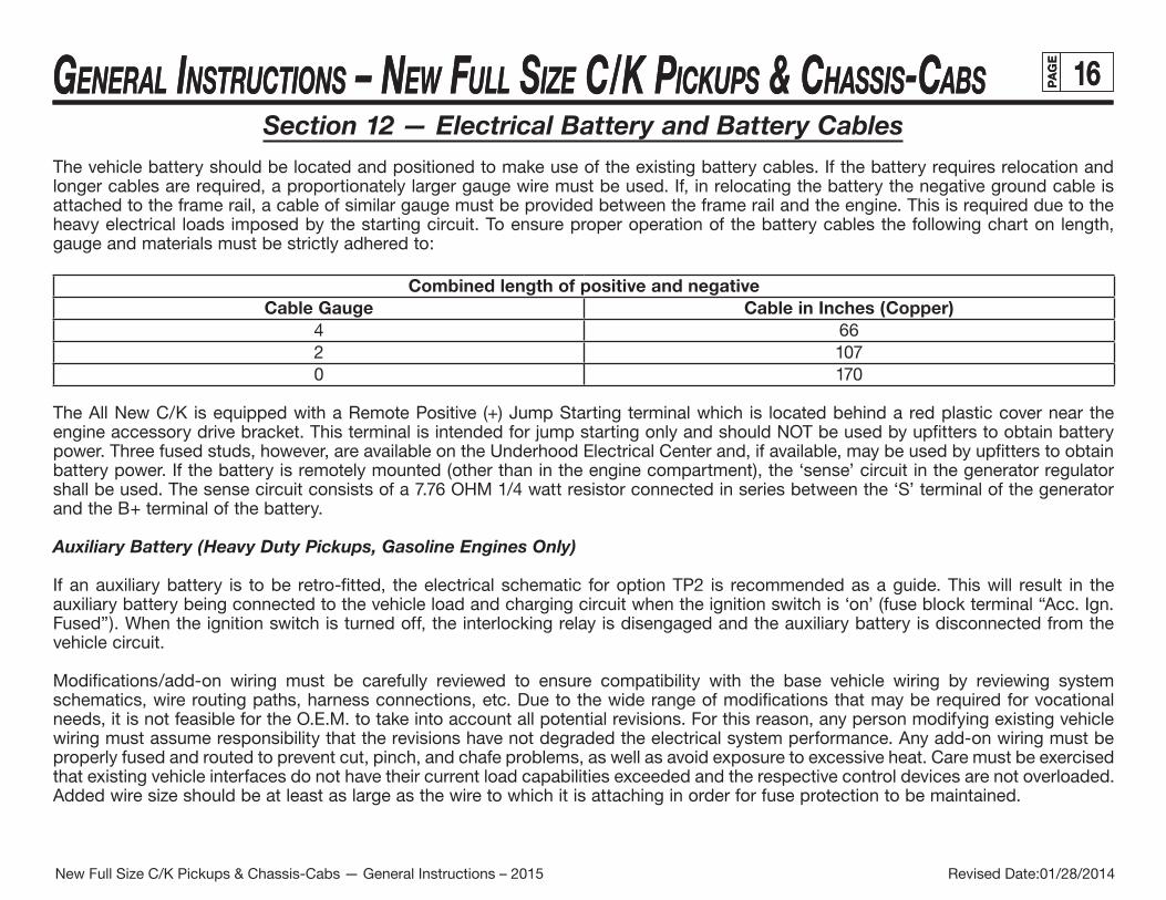
16Section 12 — Electrical Battery and Battery Cables
The vehicle battery should be located and positioned to make use of the existing battery cables. If the battery requires relocation and longer cables are required, a proportionately larger gauge wire must be used. If, in relocating the battery the negative ground cable is attached to the frame rail, a cable of similar gauge must be provided between the frame rail and the engine. This is required due to the heavy electrical loads imposed by the starting circuit. To ensure proper operation of the battery cables the following chart on length, gauge and materials must be strictly adhered to:
Combined length of positive and negativeCable Gauge Cable in Inches (Copper)
4 662 1070 170
The All New C/K is equipped with a Remote Positive (+) Jump Starting terminal which is located behind a red plastic cover near the engine accessory drive bracket. This terminal is intended for jump starting only and should NOT be used by upfitters to obtain battery power. Three fused studs, however, are available on the Underhood Electrical Center and, if available, may be used by upfitters to obtain battery power. If the battery is remotely mounted (other than in the engine compartment), the ‘sense’ circuit in the generator regulator shall be used. The sense circuit consists of a 7.76 OHM 1/4 watt resistor connected in series between the ‘S’ terminal of the generator and the B+ terminal of the battery.
Auxiliary Battery (Heavy Duty Pickups, Gasoline Engines Only)
If an auxiliary battery is to be retro-fitted, the electrical schematic for option TP2 is recommended as a guide. This will result in the auxiliary battery being connected to the vehicle load and charging circuit when the ignition switch is ‘on’ (fuse block terminal “Acc. Ign. Fused”). When the ignition switch is turned off, the interlocking relay is disengaged and the auxiliary battery is disconnected from the vehicle circuit.
Modifications/add-on wiring must be carefully reviewed to ensure compatibility with the base vehicle wiring by reviewing system schematics, wire routing paths, harness connections, etc. Due to the wide range of modifications that may be required for vocational needs, it is not feasible for the O.E.M. to take into account all potential revisions. For this reason, any person modifying existing vehicle wiring must assume responsibility that the revisions have not degraded the electrical system performance. Any add-on wiring must be properly fused and routed to prevent cut, pinch, and chafe problems, as well as avoid exposure to excessive heat. Care must be exercised that existing vehicle interfaces do not have their current load capabilities exceeded and the respective control devices are not overloaded. Added wire size should be at least as large as the wire to which it is attaching in order for fuse protection to be maintained.
Revised Date:01/28/2014New Full Size C/K Pickups & Chassis-Cabs — General Instructions – 2015
GENERAL INSTRUCTIONS – NEW FULL SIZE C/K PICKUPS & CHASSIS-CABS PA
GE
17GENERAL INSTRUCTIONS – NEW FULL SIZE C/K PICKUPS & CHASSIS-CABS PA
GE
17(Section 12 — continued from previous page)
A wiring repair kit is available through your dealer. This kit contains instructions, tools and components for making repairs to wiring harness components. This kit would also greatly assist in accomplishing necessary add-on wiring, such as body marker lamps, so that system reliability/durability is maintained.
Electrical wiring components can be obtained through your authorized GM dealer. Many Packard Electric components are also available through Pioneer Standard Company (1-800-PACKARD). Pioneer may also be able to assist in making necessary wiring additions by providing custom wiring stubs or jumpers to your specifications.
Section 13 — CoolingTo provide satisfactory engine cooling, the following conditions must be met:
1. Do not locate any large objects in front of the radiator core or grille, such as batteries, spare tires, lights/sirens, etc. They restrict air flow into the radiator core and influence fan blade stress.
2. Grille opening, size configuration and the external baffles provided should not be altered in any manner. Any reduction in cooling ability may adversely affect engine/transmission performance.
3. Fan clutches not conforming to the original equipment specifications may not operate correctly and may stay “on” continuously, never come on, or cycle on and off excessively. This will result in a reduction of fuel economy, engine overheat at times, and annoying cycling respectively.
4. Heavy duty cooling equipment is required when snow plows, winches, etc., are installed.
5. If a heater unit is not installed in the vehicle or a heater shut-off valve is required, a line connecting the heater connection on the engine to the heater connection on the surge tank outlet hose (gas) or lower radiator hose (diesel) must be installed. When a shut-off valve is required in the heating system, it must be teed into the system in such a manner as to maintain continuous flow between engine heater connection – surge tank outlet hose/lower radiator hose connection at all times.
Do not install any internal flow restrictors.
NOTE: SCPI unit does not have internal coolant passages.
Revised Date:01/28/2014New Full Size C/K Pickups & Chassis-Cabs — General Instructions – 2015