Embed Size (px)
Citation preview
Isolation - Before commencing work make sure that the unit is electrically isolated from the mains and
switched live supply.
111. 06. 18. Leaflet Number 671504
Genie-DC and DCE 12V and 230VUniversal Surface Mounted FansInstallation and Maintenance
superimposed on page 6.
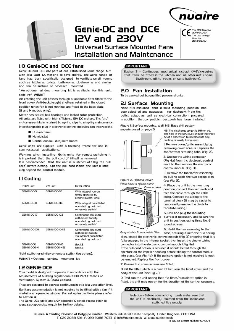
Figure 2. Remove cover.
Cover screws.
NB. The discharge spigot is 98mm od.The hole in the structure should thereforebe of a dimension to accomodate anyducting or cavity lining used.
Press tabs to release cover.
The EMC Directive 2014/30/EU The Low Voltage Directive 2014/35/EU
Easy stretch fit removable filter.
System 3 – Continuous mechanical extract (MEV) requires that fans be fitt ed in the kitchen and all other wet rooms
(bathroom, utility room, en-suite bathroom).
1.0 Genie-DC and DCE fansGenie-DC and DCE are part of our established Genie range but with low watt DC mot or s to save energy. The Genie range of fans has been specifically designed to ventilate small rooms such as kitchens, toilets, bathrooms, cloakrooms and similar and can be surface or recessed mounted.* An optional window mounting kit is available for this unit,code ref: WINKITAir entering the unit passes through a washable filter fitted to the front cover. Anti-backdraught shutters, retained in the closedposition when fan is not running, are fitted to the base plate(S and H models only).Motor has sealed, ball bearings and locked rotor protection.All units are fitted with high efficiency 12V DC motors. The fan/motor assembly is retained by spring clips to simplify maintenance.Interchangeable plug in electronic control modules can incorporate:
■ Run-on timer■ Humidistat■ Continuous low duty with boost.
Genie units are supplied with a finishing frame for use in semi-recessed applications.
Warning: when installing Genie units for remote switching it is important that the pull cord (if fitted) is removed. It is recommended that the unit is switched of f (by the pull cord) before cutting. Cut the pull cord inside the unit a little way beyond the control module.
1.1 Coding230V unit 12V unit Descr iption
GENIE-DC-S GENIE-DC-S12 With integral run-ontimer, operated byremote switch* only.
GENIE-DC-H GENIE-DC-H12 With integral humidistat,operated by pull cordor remote switch*
GENIE-DC-X GENIE-DC-X12 Continuous low dutywith boost facilityoperated by pull cordor remote switch*
GENIE-DC-XH GENIE-DC-XH12 Continuous low dutywith boost facilityvia internal humidistatoperated by pull cord
GENIE-DCE GENIE-DCE-12 See 1.2GENIE-DCE-H GENIE-DCE-H12 See 1.2
*light switch or similar or remote switch (by others).
WINKIT = Optional window mounting kit.
1.2 GENIE-DCEThis model is designed to operate in accordance with the requirements of building regulations 2000 Part F Means of Ventilation, System 3. (2010 Edition).
They are designed to operate continuously at a low ventilation level.
Sanitary accommodation is not required to be fitted with a fan if it contains an openable window. For set up instructions please refer to section 4.The Genie-DCE units are SAP appendix Q listed. Please refer to www.sap-appendixq.org.uk for further details.
2.0 Fan InstallationTo be carried out by qualified personnel only.
2.1 Surface MountingNot e. It is assumed that a solid mounting position has been select ed and passages for ductwork fr om the outlet spigot, as well as electrical connection prepared. In addition that compatible ductwork has been installed.
Figure 1. Surface mounted, wall. NB. Base drill pattern
1. Remove cover/grille assembly byremoving cover screws. Depress thetop/bottom retaining tabs. (Fig. 2).
2. Unplug the wiring connector(Fig 4a) from the electronic controlmodule, then remove the electroniccontrol module. (Fig. 3).
3. Remove the fan/motor assemblyby pulling aside the two spring clips(see Fig. 3).
4. Place the unit in the mountingposition, connect the ductwork andfeed the cable through the cableentry. Connect the wiring to theterminal block (it may be easier totemporarily remove the block tofacilitate wiring).
5. Drill and plug the mountingsurface if necessary and secure theunit in position, using three No. 6wood screws.
6. Re-fit the fan assembly to thecase, securing it with the two spring
clips. Install the electronic control module (Fig. 3) ensuring that it isfully engaged in the internal socket then insert the plug-in wiringconnector into the electronic control module (Fig 4a).If the pull-cord option is required it should be fed through the aperture on the impeller housing before sliding the control moduleinto place. (see Fig 4b). If the pullcord option is not required it mustbe removed. Replace the front cover.
7. Ensure two cover screws are fitted.
8. Fit the filter which is a push fit between the front cover and thebody of the unit (see Fig. 2).
9. Test run the unit noting that if a timer/humidistat option isfitted, the unit may run-on for the duration of the control sequence.
Nuaire: A Trading Division of Polypipe Limited Western Industrial Estate Caerphilly United Kingdom CF83 1NA T: 029 2088 5911 F: 029 2088 7033 E: [email protected] W: www.nuaire.co.uk
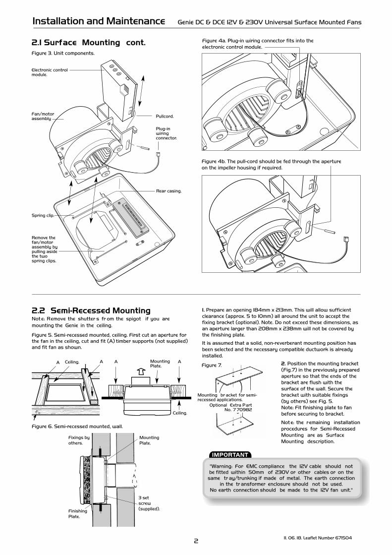
Mounting br acket for semi-recessed applications.
Optional Extra Part No. 7 70982
1. Prepare an opening 184mm x 213mm. This will allow sufficient clearance (approx. 5 to 10mm) all around the unit to accept the fixing bracket (optional). Note. Do not exceed these dimensions, as an aperture larger than 208mm x 238mm will not be covered by the finishing plate.
It is assumed that a solid, non-reverberant mounting position has been selected and the necessary compatible ductwork is already installed.
2. Position the mounting bracket (Fig.7) in the previously prepared aperture so that the ends of the bracket are flush with the surface of the wall. Secure the bracket with suitable fixings(by others) see Fig. 5.Note: Fit finishing plate to fan before securing to bracket.
Not e: the remaining installation procedures for Semi-Recessed Mounting are as Surface Mounting description.
Plug-in wiring connector.
Installation and Maintenance Genie DC & DCE 12V & 230V Universal Surface Mounted Fans
211. 06. 18. Leaflet Number 671504
Remove thefan/motorassembly bypulling asidethe twospring clips.
Pullcord.
Figure 4a. Plug-in wiring connector fits into the electronic control module.
Spring clip.
Figure 4b. The pull-cord should be fed through the apertureon the impeller housing if required.
Rear casing.
"Warning: For EMC compliance the 12V cable should not be fitted within 50mm of 230V or other cables or on the
same tr ay/trunking if made of metal. The earth connection in the tr ansformer enclosure should not be used.
No earth connection should be made to the 12V fan unit."
Fixings byothers.
FinishingPlate.
3 setscrew(supplied).
MountingPlate.
2.2 Semi-Recessed MountingNot e: Remove the shutter s fr om the spigot if you are mounting the Genie in the ceiling.
Figure 5. Semi-recessed mounted, ceiling. First cut an aperture for the fan in the ceiling, cut and fit (A) timber supports (not supplied) and fit fan as shown.
Figure 6. Semi-recessed mounted, wall.
AA AA
Ceiling.
MountingPlate.
Ceiling.Figure 7.
2.1 Surface Mounting cont.Figure 3. Unit components.
Electronic control module.
Fan/motorassembly
311. 06. 18. Leaflet Number 671504
Installation and Maintenance Genie DC & DCE 12V & 230V Universal Surface Mounted Fans
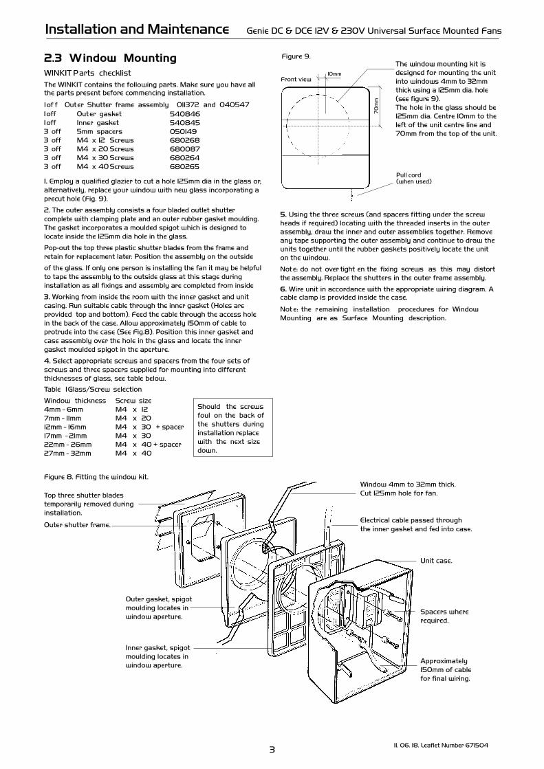
Front view10mm
70
mm
.
Figure 9.The window mounting kit is designed for mounting the unit into windows 4mm to 32mm thick using a 125mm dia. hole (see figure 9).The hole in the glass should be 125mm dia. Centre 10mm to the left of the unit centre line and 70mm from the top of the unit.
Pull cord (when used)
Should the screws foul on the back of the shutters during installation replace with the next size down.
Figure 8. Fitting the window kit.Window 4mm to 32mm thick. Cut 125mm hole for fan.
Electrical cable passed through the inner gasket and fed into case.
Unit case.
Spacers where required.
Approximately 150mm of cable for final wiring.
Inner gasket, spigotmoulding locates in window aperture.
Top three shutter blades temporarily removed duringinstallation.
Outer shutter frame.
Outer gasket, spigotmoulding locates in window aperture.
2.3 Window MountingWINKIT Parts checklistThe WINKIT contains the following parts. Make sure you have all the parts present before commencing installation.
1 of f Outer Shutter frame assembly 011372 and 040547540846540845050149680268680087680264
1 off Outer gasket1 off Inner gasket3 off 5mm spacers 3 off M4 x 12 Screws 3 off M4 x 20 Screws 3 off M4 x 30 Screws 3 off M4 x 40 Screws 680265
1. Employ a qualified glazier to cut a hole 125mm dia in the glass or,alternatively, replace your window with new glass incorporating aprecut hole (Fig. 9).
2. The outer assembly consists a four bladed outlet shuttercomplete with clamping plate and an outer rubber gasket moulding.The gasket incorporates a moulded spigot which is designed tolocate inside the 125mm dia hole in the glass.
Pop-out the top three plastic shutter blades from the frame andretain for replacement later. Position the assembly on the outside
of the glass. If only one person is installing the fan it may be helpfulto tape the assembly to the outside glass at this stage during installation as all fixings and assembly are completed from inside
3. Working from inside the room with the inner gasket and unitcasing. Run suitable cable through the inner gasket (Holes areprovided top and bottom). Feed the cable through the access holein the back of the case. Allow approximately 150mm of cable toprotrude into the case (See Fig.8). Position this inner gasket andcase assembly over the hole in the glass and locate the innergasket moulded spigot in the aperture.
4. Select appropriate screws and spacers from the four sets ofscrews and three spacers supplied for mounting into differentthicknesses of glass, see table below.
Table 1 Glass/Screw selection
Window thickness4mm - 6mm
Screw size M4 x 12
7mm - 11mm12mm - 16mm17mm - 21mm22mm - 26mm27mm - 32mm
M4 x 20M4 x 30 + spacer M4 x 30M4 x 40 + spacer M4 x 40
5. Using the three screws (and spacers fitting under the screw heads if required) locating with the threaded inserts in the outer assembly, draw the inner and outer assemblies together. Remove any tape supporting the outer assembly and continue to draw the units together until the rubber gaskets positively locate the unit on the window.
Not e: do not over tight en the fixing screws as this may distort the assembly. Replace the shutters in the outer frame assembly.
6. Wire unit in accordance with the appropriate wiring diagram. A cable clamp is provided inside the case.
Not e: the remaining installation procedures for Window Mounting are as Surface Mounting description.
Ensure boost speed is set higher than trickle speed setting
12V fan units must be installed in accor dance with these instructions and IEE Wiring Regulations BS7 6 7 1
for SEL V installations.
Isolation - Before commencing work mak e sure the unit is electrically isolated fr om the mains and switched live supply. Means for double pole disconnection must be incorporated in
the fixed wiring in accordance with the wiring regulations.
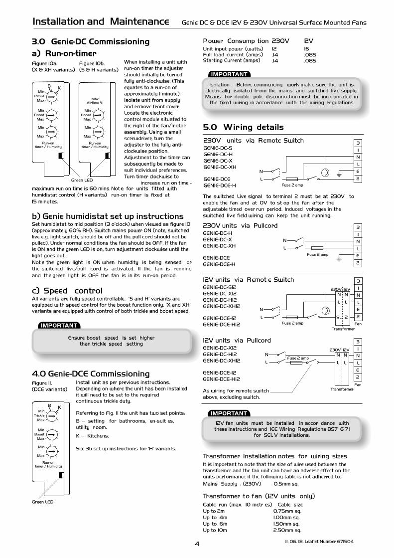
3.0 Genie-DC Commissioning a) Run-on-timer
When installing a unit withrun-on timer the adjustershould initially be turnedfully anti-clockwise. (Thisequates to a run-on ofapproximately 1 minute).Isolate unit from supply and remove front cover. Locate the electronic control module situated tothe right of the fan/motorassembly. Using a smallscrewdriver, turn theadjuster to the fully anti-clockwise position.Adjustment to the timer can subsequently be made tosuit individual preferences.Turn timer clockwise to
increase run on time - maximum run on time is 60 mins. Not e: for units fitted with humidistat control (H variants) run-on timer is fixed at 15 minutes.
b) Genie humidistat set up instructionsSet humidistat to mid position (3 o’clock) when viewed as figure 10 (approximately 60% RH). Switch mains power ON (note, switched live e.g. light switch, should be off and the pull cord should not be pulled). Under normal conditions the fan should be OFF. If the fan is ON and the green LED is on, turn adjustment clockwise until the light goes out.Not e the green light is ON when humidity is being sensed or the switched live/pull cord is activated. If the fan is running and the green light is OFF the fan is in its run-on period.
c) Speed controlAll variants are fully speed controllable. ‘S and H’ variants are equipped with speed control for the boost function only. ‘X and XH’ variants are equipped with control of both trickle and boost speed.
4.0 Genie-DCE CommissioningInstall unit as per previous instructions. Depending on where the unit has been installed it will need to be set to the required continuous trickle duty.
Referring to Fig. 11 the unit has two set points:
B – setting for bathrooms, en-suit es, utility room.
K – Kitchens.
See 3b set up instructions for ‘H’ variants.
P ower Consump tion 230V 12V12 16.14 .085
Unit input power (watts) Full load current (amps) Starting Current (amps) .14 .085
5.0 Wiring details
4 11. 06. 18. Leaflet Number 671504
Installation and Maintenance Genie DC & DCE 12V & 230V Universal Surface Mounted Fans
L
N
3
1
2
N
L
E
Fuse 2 amp
230V units via Remote SwitchGENIE-DC-S GENIE-DC-H GENIE-DC-XGENIE-DC-XH
GENIE-DCE GENIE-DCE-H
230V units via PullcordGENIE-DC-H GENIE-DC-XGENIE-DC-XH
GENIE-DCE GENIE-DCE-H
L
N
3
1
2
E
N
L
Fan
Fuse 2 amp
Transformer
230V 12VN
L
N
L
GENIE-DC-X12GENIE-DC-H12GENIE-DC-XH12
GENIE-DCE-12GENIE-DCE-H12
As wiring for remote switch above, excluding switch.
Transformer Installation notes for wiring sizesIt is important to note that the size of wire used between the transformer and the fan unit can have an adverse effect on the units performance if the following table is not adherred to.Mains Supply : (230V) 0.5mm sq.
Transformer to fan (12V units only)Cable run (max. 10 metr es) Cable sizeUp to 2m 0.75mm sq.
1.00mm sq.1.50mm sq.
Up to 4m Up to 6m Up to 10m 2.50mm sq.
L
N
3
1
2
Fuse 2 amp E
N
L
12V units via Remot e SwitchGENIE-DC-S12GENIE-DC-X12GENIE-DC-H12GENIE-DC-XH12
GENIE-DCE-12GENIE-DCE-H12
12V units via Pullcord
The switched Live signal to terminal 2 must be at 230V toenable the fan and at 0V to st op the fan after the adjustable timed over run period. Induced voltages in the switched live field wiring can keep the unit running.
Run-ontimer / Humidity
B KMin
TrickleMax
MinBoost
Max
Min
Max
Run-ontimer / Humidity
MinBoost
Max
Min
Max
MaxAirflow %
L
N
3
1
2
N
L
E
Fuse 2 amp Fan
230V 12VN
L
N
L
SL 2
Transformer
Run-ontimer / Humidity
B KMin
TrickleMax
MinBoost
Max
Min
Max
Figure 10a.(X & XH variants)
Figure 11.(DCE variants)
Green LED
Figure 10b.(S & H variants)
Green LED
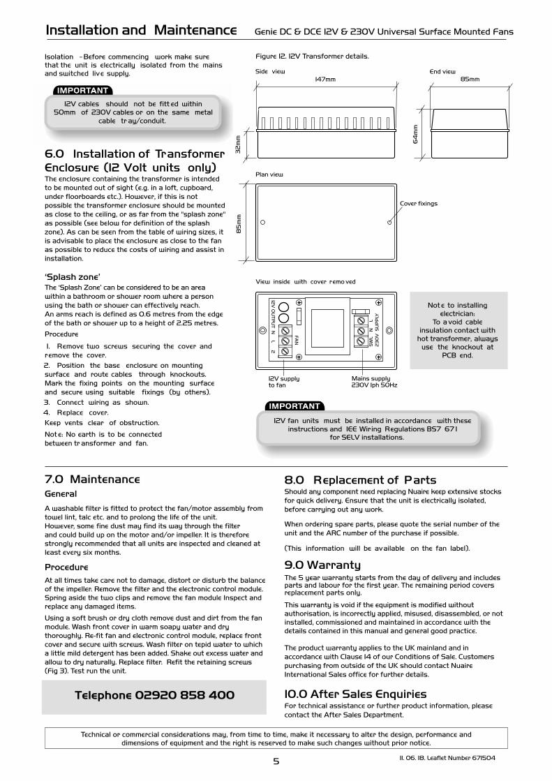
147mm 85mm
64
mm
32
mm
85
mm
End view
Plan view
Cover fixings
View inside with cover remo ved12
V O
UT
PU
T N
L 2
FA
N
SW
L
N
L2
30
V S
UP
PLY
12V supplyto fan
Mains supply230V 1ph 50Hz
12V fan units must be installed in accordance with these instructions and IEE Wiring Regulations BS7 67 1
for SELV installations.
5 11. 06. 18. Leaflet Number 671504
Installation and Maintenance Genie DC & DCE 12V & 230V Universal Surface Mounted Fans
Isolation - Before commencing work make sure that the unit is electrically isolated from the mains and switched live supply.
Figure 12. 12V Transformer details.
Side view
7.0 MaintenanceGeneral
A washable filter is fitted to protect the fan/motor assembly from towel lint, talc etc. and to prolong the life of the unit. However, some fine dust may find its way through the filter and could build up on the motor and/or impeller. It is therefore strongly recommended that all units are inspected and cleaned at least every six months.
ProcedureAt all times take care not to damage, distort or disturb the balance of the impeller. Remove the filter and the electronic control module. Spring aside the two clips and remove the fan module Inspect and replace any damaged items.
Using a soft brush or dry cloth remove dust and dirt from the fan module. Wash front cover in warm soapy water and dry thoroughly. Re-fit fan and electronic control module, replace front cover and secure with screws. Wash filter on tepid water to which a little mild detergent has been added. Shake out excess water and allow to dry naturally. Replace filter. Refit the retaining screws (Fig 3). Test run the unit.
8.0 Replacement of PartsShould any component need replacing Nuaire keep extensive stocks for quick delivery. Ensure that the unit is electrically isolated, before carrying out any work.
When ordering spare parts, please quote the serial number of the unit and the ARC number of the purchase if possible.
(This information will be available on the fan label).
9.0 WarrantyThe 5 year warranty starts from the day of delivery and includes parts and labour for the first year. The remaining period covers replacement parts only.
This warranty is void if the equipment is modified without authorisation, is incorrectly applied, misused, disassembled, or not installed, commissioned and maintained in accordance with the details contained in this manual and general good practice.
The product warranty applies to the UK mainland and in accordance with Clause 14 of our Conditions of Sale. Customers purchasing from outside of the UK should contact Nuaire International Sales office for further details.
10.0 After Sales EnquiriesFor technical assistance or further product information, please contact the After Sales Department.
Telephone 02920 858 400
Technical or commercial considerations may, from time to time, make it necessary to alter the design, performance and dimensions of equipment and the right is reserved to make such changes without prior notice.
Not e to installing electrician:
To a void cable insulation contact with
hot transformer, always use the knockout at
PCB end.
12V cables should not be fitt ed within 50mm of 230V cables or on the same metal
cable tr ay/conduit.
6.0 Installation of TransformerEnclosure (12 Volt units only)The enclosure containing the transformer is intended to be mounted out of sight (e.g. in a loft, cupboard, under floorboards etc.). However, if this is not possible the transformer enclosure should be mounted as close to the ceiling, or as far from the "splash zone" as possible (see below for definition of the splash zone). As can be seen from the table of wiring sizes, it is advisable to place the enclosure as close to the fan as possible to reduce the costs of wiring and assist in installation.
‘Splash zone’The ‘Splash Zone’ can be considered to be an area within a bathroom or shower room where a person using the bath or shower can effectively reach. An arms reach is defined as 0.6 metres from the edge of the bath or shower up to a height of 2.25 metres.
Procedure
1. Remove two screws securing the cover andremove the cover.2. Position the base enclosure on mounting surface and route cables through knockouts.Mark the fixing points on the mounting surface and secure using suitable fixings (by others).3. Connect wiring as shown.4. Replace cover.Keep vents clear of obstruction.
Not e: No earth is to be connected between tr ansformer and fan.
6 11. 06. 18. Leaflet Number 671504
Installation and Maintenance Genie DC & DCE 12V & 230V Universal Surface Mounted Fans
Western Industrial Estate
Caerphilly United Kingdom
CF83 1NA
T: 029 2088 5911
F: 029 2088 7033
W: www.nuaire.co.uk
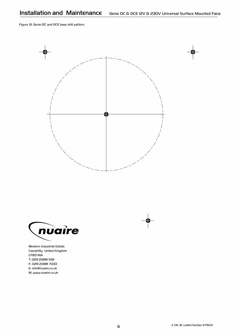
Figure 13. Genie-DC and DCE base drill pattern.