Embed Size (px)
Citation preview
Scale Drift Correction of CameraGeo-Localization using Geo-Tagged Images
Kazuya Iwami1 and Satoshi Ikehata2 and Kiyoharu Aizawa1
1 The University of Tokyo, Japan{iwami,aizawa}@hal.t.u-tokyo.ac.jp
2 National Institute of Informatics, [email protected]
Abstract. Camera geo-localization from a monocular video is a funda-mental task for video analysis and autonomous navigation. Although 3Dreconstruction is a key technique to obtain camera poses, monocular 3Dreconstruction in a large environment tends to result in the accumulationof errors in rotation, translation, and especially in scale: a problem knownas scale drift. To overcome these errors, we propose a novel frameworkthat integrates incremental structure from motion (SfM) and a scale driftcorrection method utilizing geo-tagged images, such as those provided byGoogle Street View. Our correction method begins by obtaining sparse6-DoF correspondences between the reconstructed 3D map coordinatesystem and the world coordinate system, by using geo-tagged images.Then, it corrects scale drift by applying pose graph optimization overSim(3) constraints and bundle adjustment. Experimental evaluations onlarge-scale datasets show that the proposed framework not only suffi-ciently corrects scale drift, but also achieves accurate geo-localization ina kilometer-scale environment.
1 Introduction
Camera geo-localization from a monocular video in a kilometer-scale environ-ment is a essential technology for AR, video analysis, and autonomous naviga-tion. To achieve accurate geo-localization, 3D reconstruction from a video is akey technique. Incremental structure from motion (SfM) and visual simultaneouslocalization and mapping (visual SLAM) achieve large-scale 3D reconstructionsby simultaneously localizing camera poses with six degrees-of-freedom (6-DoF)and reconstructing a 3D environment map [1,2].
Unlike for a stereo camera, an absolute scale of the real world cannot bederived using a single observation from a monocular camera. Although it ispossible to estimate an environment’s relative scale from a series of monocularobservations, errors in the relative scale estimation accumulate over time, andthis is referred to as scale drift [3,4].
For an accurate geo-localization not affected by scale drift ,prior informationin a geographic information system (GIS) has been utilized in previous stud-ies. For example, point clouds, 3D models, building footprints, and road maps
arX
iv:1
808.
0854
4v1
[cs
.CV
] 2
6 A
ug 2
018
2 K. Iwami and S. Ikehata and K. Aizawa
have been proven to be efficient for correcting reconstructed 3D maps [5,6,7,8,9].However, these priors are only available in limited situations, e.g., in an areathat is observed in advance, or in an environment consisting of simply-shapedbuildings. Therefore, there is a good chance that other GIS information can helpto extend the area in which a 3D map can be corrected.
Hence, in this paper, motivated by the recent availability of massive publicrepositories of geo-tagged images taken all over the world, we propose a novelframework for correcting the scale drift of monocular 3D reconstruction by uti-lizing geo-tagged images, such as those in Google Street View [10], and achieveaccurate camera geo-localization. Owing to the high coverage of Google StreetView, our proposal is more scalable than those in previous studies.
The proposed framework integrates incremental SfM and a scale drift correc-tion method utilizing geo-tagged images. Our correction method begins by com-puting 6-DoF correspondences between the reconstructed 3D map coordinatesystem and the world coordinate system, by using geo-tagged images. Owing tosignificant differences in illumination, viewpoint, and the environment resultingfrom differences in time, it tends to be difficult to acquire correspondences be-tween video frames and geo-tagged images (Fig. 2). Therefore, a new correctionmethod that can deal with the large scale drift of a 3D map using a limited num-ber of correspondences is required. Bundle adjustment with constraints of globalposition information, which represents one of the most important correctionmethods, cannot be applied directly. This is because bundle adjustment tendsto get stuck in a local minimum when starting from a 3D map including largeerrors [4]. Hence, the proposed correction method consists of two coarse-to-finesteps: pose graph optimization over Sim(3) constraints, and bundle adjustment.In these steps, our key idea is to extend the pose graph optimization methodproposed for the loop closure technique of monocular SLAM [4], such that it in-corporates the correspondences between the 3D map coordinate system and theworld coordinate system. This step corrects the large errors, and enables bun-dle adjustment to obtain precise results. After implementing this framework, weconducted experiments to evaluate the proposal.
The contributions of this work are as follows. First, we propose a novelframework for camera geo-localization that can correct scale drift by utilizinggeo-tagged images. Second, we extend the pose graph optimization approachto dealing with scale drift using a limited number of correspondences to geo-tags. Finally, we validate the effectiveness of the proposal through experimentalevaluations on kilometer-scale datasets.
2 Related Work
2.1 Monocular 3D Reconstruction
Incremental SfM and visual SLAM are important approaches to reconstructing3D maps from monocular videos. Klein et al. proposed PTAM for small ARworkspaces [11]. Mur-Artal et al. developed ORB-SLAM, which can reconstruct
Scale Drift Correction of Camera Geo-Localization using Geo-Tagged Images 3
large-scale outdoor environments [2]. For accurate 3D reconstruction, the loopclosure technique has commonly been employed in recent SLAM approaches [4,2].Loop closure deals with errors that accumulate between two camera poses thatoccur at the same location, i.e., when the camera trajectory forms a loop. Lu andMilios [12] formulated this technique as a pose graph optimization problem, andStrasdat et al. [4] extended pose graph optimization to deal with scale drift formonocular visual SLAM. It is certain that loop closure can significantly improve3D maps, but this is only effective if a loop exists in the video.
2.2 Geo-registration of Reconstructions
Correcting reconstructed 3D maps by using geo-referenced information has beenregarded as a geo-registration problem. Kaminsky et al. proposed a methodthat aligns 3D reconstructions to 2D aerial images [13]. Wendel et al. used anoverhead digital surface model (DSM) for the geo-registration of 3D maps [14].Similar to our work, Wang et al. used Google Street View geo-tagged images anda Google Earth 3D model for the geo-registration of reconstructed 3D maps [15].However, because all these methods focus on estimating a best-fitting similaritytransformation to geo-referenced information, they only correct the global scalein terms of 3D map correction.
Methods for geo-registration using non-linear transformations have also beenproposed. To integrate GPS information, Lhuillier et al. proposed incrementalSfM using bundle adjustment with constraints from GPS [16], and Rehder et al.formulated a global pose estimation problem using stereo visual odometry, iner-tial measurements, and infrequent GPS information as a 6-DoF pose graph op-timization problem [17]. In terms of correcting camera poses using sparse globalinformation, Rehder’s method is similar to our pose graph optimization ap-proach. However, our 7-DoF pose graph optimization differs in focusing on scaledrift resulting from monocular 3D reconstruction, and in utilizing geo-taggedimages. In addition to GPS information, various kinds of reference data havebeen used for the non-linear geo-registration or geo-localization of a video, suchas point clouds [5,6], 3D models [7], building footprints [8], and road maps [9].In this paper, we address a method that introduces geo-tagged images to thenon-linear geo-registration of 3D maps.
3 Proposed Method
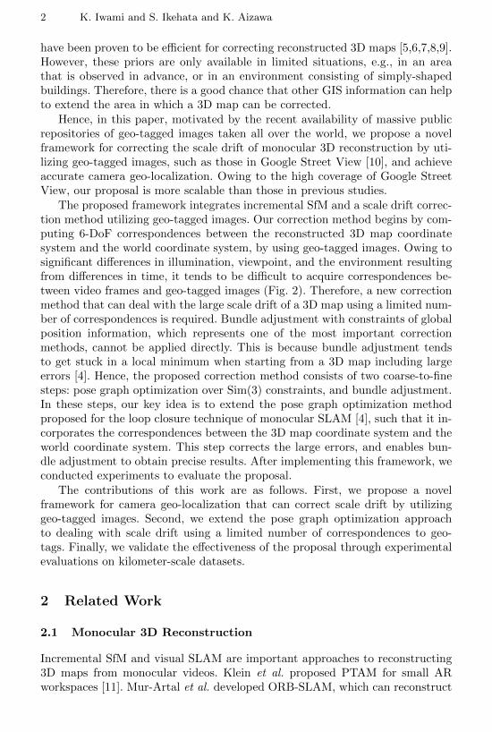
Fig. 1 provides a flowchart of the proposed framework, which is roughly dividedinto three parts. The first part is incremental SfM, and is described in Sec. 3.2.The second part computes 6-DoF correspondences between the 3D map coordi-nate system and the world coordinate system (as defined below), by making useof geo-tagged images (Sec. 3.3). The third part then uses the correspondences tocorrect the scale drift of the 3D map, by applying pose graph optimization overSim(3) constraints (Sec. 3.5) and bundle adjustment (Sec. 3.6) incrementally.The initialization of the scale drift correction method is described in Sec. 3.4.
4 K. Iwami and S. Ikehata and K. Aizawa
New image
Is the image KF?
Similar GI Retrieval
Keypoint Matching
Enough valid matches?
Pose Graph Optimization
Bundle Adjustment
Incremental SfM
GI Localization
Initializationyes
yes
Obtaining correspondences btw 3D map & world coordinate system
Scale drift correction
Fig. 1. A flowchart of our proposal. KF and GI denote a keyframe and geo-taggedimage, respectively. Initialization is performed only once in a whole reconstruction.
3.1 World Coordinate System
In this paper, the world coordinates are represented by 3D coordinates (x, y, z),where the xz-plane corresponds to the Universal Transverse Mercator (UTM)coordinate system, which is an orthogonal coordinate system using meters, andy corresponds to the height from the ground in meters. The UTM coordinatescan be converted into latitude and longitude if necessary.
3.2 Incremental SfM
As large-scale incremental SfM, we use ORB-SLAM [2] (with no real-time con-straints). This is one of the best-performing monocular SLAM systems. Framesthat are important for 3D reconstruction are selected as keyframes by ORB-SLAM. Every time a new keyframe is selected, our correction method is per-formed, and the 3D map reconstructed up to that point is corrected. In the 3Dreconstruction, we identify 3D map points and their corresponding 2D keypointsin the keyframes (collectively denoted by Cmap-kf).
Our proposed framework does not depend on a certain 3D reconstructionmethod, and can be applied to the other monocular 3D reconstruction methods,such as incremental SfM and feature-based visual SLAM.
Scale Drift Correction of Camera Geo-Localization using Geo-Tagged Images 5
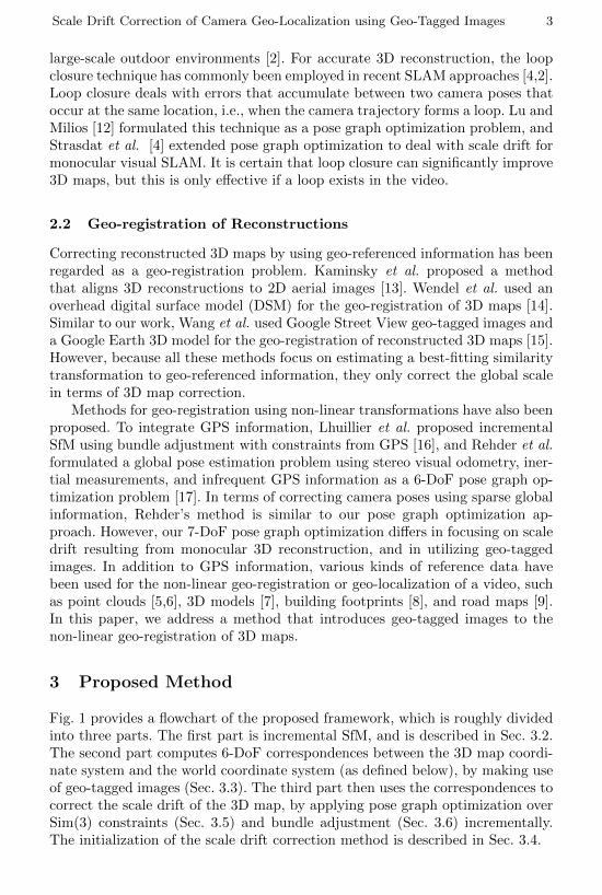
Fig. 2. Examples of keypoint matches between keyframes (without blue squares) andgeo-tagged images of Google Street View (with blue squares) after kVLD validation.Top: pairs of images where valid matches are found. Yellow lines denote kVLD graphstructures, which are composed of inliers. Bottom: rejected pairs of images where a suf-ficient number of matches is not found because of differences in illumination, viewpoint,and environment, despite being taken in almost the same location.
3.3 Obtaining Correspondences between 3D Map and WorldCoordinates
Here, we describe the second part of the proposed method, which uses geo-taggedimages to compute a 6-DoF correspondence, Cmap-world, between the 3D map andworld coordinate system. For this purpose, we modify Agarwal’s method [18] tointegrate it into ORB-SLAM. This part consists of the following four steps: geo-tagged image collection, similar geo-tagged image retrieval, keypoint matching,and geo-tagged image localization.
Geo-tagged Image Collection. Google Street View [10] is a browsable street-level GIS, which is one of the largest repositories of global geo-tagged images(i.e., images and their associated geo-tags). All images are high-resolution RGBpanorama images, containing highly accurate world positions [19]. We make useof this data by converting each panorama image into eight rectilinear imageswith the same field-of-view as our input video, with eight horizontal directions.Note that because each geo-tag has a position and rotation in the world coordi-nates, we can obtain the 6-DoF correspondences between the 3D map coordinatesystem and world coordinate system if geo-tagged images are localized in the 3Dmap coordinate system.
Similar Geo-tagged Image Retrieval. When a new keyframe is selected,we retrieve the top-k similar geo-tagged images. The retrieval system employs abag-of-words approach based on SIFT descriptors [18].
Keypoint Matching. Given the pairs of keyframes and retrieved geo-tagged
6 K. Iwami and S. Ikehata and K. Aizawa
camera poseof geo-tagged image
(node S m)relative pose constraint(edge e 1i, j , edge e 2k, l)
position of geo-tag(fixed parameter)
distance error(edge e 3m)
camera pose of key frame
(node S n)
Before Optimization After Optimization
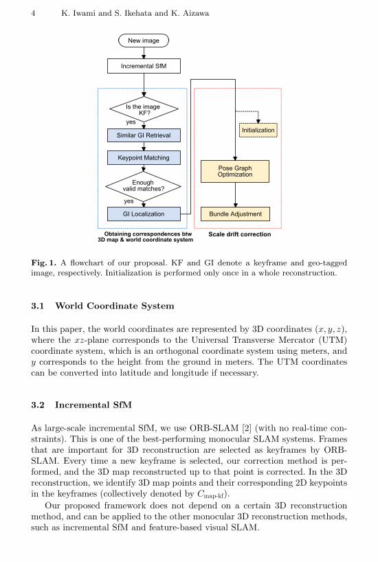
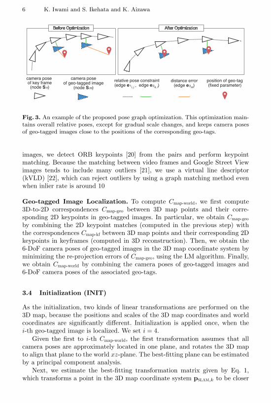
Fig. 3. An example of the proposed pose graph optimization. This optimization main-tains overall relative poses, except for gradual scale changes, and keeps camera posesof geo-tagged images close to the positions of the corresponding geo-tags.
images, we detect ORB keypoints [20] from the pairs and perform keypointmatching. Because the matching between video frames and Google Street Viewimages tends to include many outliers [21], we use a virtual line descriptor(kVLD) [22], which can reject outliers by using a graph matching method evenwhen inlier rate is around 10
Geo-tagged Image Localization. To compute Cmap-world, we first compute3D-to-2D correspondences Cmap-geo between 3D map points and their corre-sponding 2D keypoints in geo-tagged images. In particular, we obtain Cmap-geo
by combining the 2D keypoint matches (computed in the previous step) withthe correspondences Cmap-kf between 3D map points and their corresponding 2Dkeypoints in keyframes (computed in 3D reconstruction). Then, we obtain the6-DoF camera poses of geo-tagged images in the 3D map coordinate system byminimizing the re-projection errors of Cmap-geo, using the LM algorithm. Finally,we obtain Cmap-world by combining the camera poses of geo-tagged images and6-DoF camera poses of the associated geo-tags.
3.4 Initialization (INIT)
As the initialization, two kinds of linear transformations are performed on the3D map, because the positions and scales of the 3D map coordinates and worldcoordinates are significantly different. Initialization is applied once, when thei-th geo-tagged image is localized. We set i = 4.
Given the first to i-th Cmap-world, the first transformation assumes that allcamera poses are approximately located in one plane, and rotates the 3D mapto align that plane to the world xz-plane. The best-fitting plane can be estimatedby a principal component analysis.
Next, we estimate the best-fitting transformation matrix given by Eq. 1,which transforms a point in the 3D map coordinate system pSLAM,k to be closer

Scale Drift Correction of Camera Geo-Localization using Geo-Tagged Images 7
to a corresponding point in the world coordinate system pworld,k (pSLAM,k andpworld,k are denoted using a homogeneous representation):
A =
s ∗ cos(θ) 0 −s ∗ sin(θ) a
0 s 0 1s ∗ sin(θ) 0 s ∗ cos(θ) b
0 0 0 1
(1)
Using the first to i-th Cmap-world, we estimate the four matrix parameters[a, b, s, θ] by minimizing the following cost using RANSAC [23] and the Levenberg-Marquart (LM) algorithm:
E =∑
k∈1,2...i
‖pworld,k −ApSLAM,k‖2 (2)
The camera poses of the geo-tagged images in Cmap-world, keyframes, and 3D mappoint can then be transformed using the resulting matrix.
3.5 Pose Graph Optimization over Sim(3) Constraints (PGO)
We correct the 3D map focusing on scale drift by using the newest three ofCmap-world. This correction is performed every time a new Cmap-world is found afterinitialization. Then, we propose a graph-based non-linear optimization method(pose graph optimization) on Lie manifolds, which simultaneously corrects thescale drift and aligns the 3D map with the world coordinates.
Notation. A 3D rigid body transformation G ∈ SE(3) and a 3D similaritytransformation S ∈ Sim(3) are defined by Eq. 3, where R ∈ SO(3), t ∈ R3, ands ∈ R+. Here, SO(3), SE(3), and Sim(3) are Lie groups, and so(3), se(3), andsim(3) are their corresponding Lie algebras. A Lie group can be transformedinto a Lie algebra using its exponential map, and the inverse transformationis defined by the inverse logarithm map. Each Lie algebra is represented by avector of its coefficients. For example, sim(3) is represented as the seven-vectorξ = (ω1, ω2, ω3, σ, ν1, ν2, ν3)T = (ω, σ,ν)T, and the exponential map expSim(3)
and logarithm map logSim(3) are defined as in Eq. 4 and Eq. 5, respectively,where W is a term similar to Rodriguez’s formula. Further details of Sim(3) aregiven in [4].
G =
[R t0 1
]S =
[sR t0 1
](3)
expSim(3)(ξ) =
[eσ expSO(3)(ω) Wν
0 1
]= S (4)
logSim(3)(S) = expSim(3)−1(S) = ξ (5)
Proposed pose graph optimization. In a general pose graph optimizationapproach [12,17], camera poses and relative transformations between two camera
8 K. Iwami and S. Ikehata and K. Aizawa
poses are represented as elements of SE(3). However, in our approach, 6-DoFcamera poses and relative transformations are converted into 7-DoF cameraposes, represented by elements of Sim(3). This is achieved by leaving the rotationR and translation t of a camera pose unchanged, and setting the scale s to 1. Theidea that camera poses and relative pose constraints can be handled in Sim(3)was proposed by Strasdat et al. [4], for dealing with the scale drift problem inmonocular SLAM. In this paper, we introduce 7-DoF pose graph optimization,which has previously only been used in the context of loop closure, to correct3D reconstruction by utilizing sparse correspondences between two coordinatesystems. Our pose graph contains two kinds of nodes and three kinds of edges,as follows (see Fig. 3):
– Node Sn ∈ Sim(3), where n ∈ C1: the camera pose of the nth keyframe.
– Node Sm ∈ Sim(3), where m ∈ C2: the camera pose of the mth geo-taggedimage.
– Edge e1i,j , where (i, j) ∈ C3: the relative pose constraint between the ith
and jth keyframes. (Eq. 6)
– Edge e2k,l, where (k, l) ∈ C4: the relative pose constraint between the kth
keyframe and the lth geo-tagged image. (Eq. 7)
– Edge e3m , where m ∈ C2: the distance error between the position of the mth
geo-tagged image and the world position ym of the corresponding geo-tag.(Eq. 8)
e1i,j = logSim(3)(∆Si,j · Si · S−1j ) ∈ R7 (6)
e2k,l= logSim(3)(∆Sk,l · Sk · S−1l ) ∈ R7 (7)
e3m = trans(Sm)− ym ∈ R3 (8)
where trans(S) ≡ (S1,4,S2,4,S3,4)T. Here, N is the total number of keyframes,and M is the total number of geo-tagged images that have correspondencesto keyframes. The set C1 contains all the keyframes positioned between thetwo that have the newest and the third newest Cmap-world. The set C2 containsthe newest three of Cmap-world. The set C3 contains the pairs of keyframes thatobserve the same 3D map point in 3D reconstruction, and C4 contains pairsof keyframes and their corresponding geo-tagged images. Finally, ∆Si,j is theconverted Sim(3) relative transformation between Si and Sj , which is calculatedbefore the optimization and remains fixed during the optimization.
Note that we newly introduced the nodes Sm, edges e2k,l, and edges e3m
to Strasdat’s pose graph optimization. Minimizing e1i,j and e2k,lsuppresses
changes in the relative transformations between camera poses, with the exceptionof gradual scale changes. Minimizing e3m keeps the positions of the geo-taggedimages close to the positions obtained from the associated geo-tags. Our overall
Scale Drift Correction of Camera Geo-Localization using Geo-Tagged Images 9
cost function EPGO is defined as follows:
EPGO({Si}i∈C1∪C2
) = λ1∑
(i,j)∈C3
eT1i,je1i,j
+ λ2∑
(k,l)∈C4
eT2k,le2k,l
+ λ3∑m∈C2
eT3me3m
(9)
The corrected camera poses of keyframes Sn and geo-tagged images Sm areobtained by minimizing the cost function EPGO on Lie manifolds using the LMalgorithm. Following this optimization, we also reflect this correction in the 3Dmap points, as in [4].
3.6 Bundle Adjustment (BA)
Following the pose graph optimization, we refine the 3D reconstruction by ap-plying bundle adjustment with the constraints of the geo-tagged images. Bundleadjustment is a classic method that jointly refines the 3D structure and cameraposes (and camera intrinsic parameters) by minimizing the total re-projectionerrors. Each re-projection error ri,j between the ith 3D point and jth camera isdefined as:
ri,j = xi − π(RjXi + tj) (10)
π(p) = [fxpxpz
+ cx, fypypz
+ cy]T (11)
where Xi is a 3D point and xi is the 2D observation of that 3D point; Rj
and tj are the rotation and translation of the jth camera pose, respectively;p = [px,py,pz]
T is a 3D point; π(·) : R3 7→ R2 is the projection function;(fx, fy) is the focal length; and (cx, cy) is the center of projection.
To incorporate global position information of geo-tagged images with bundleadjustment, we add a penalty term corresponding to the constraint for a geo-tagged image [16]. The total cost function with this constraint is given by:
EBA({Xi
}i∈C5
,{Tj
}j∈C1
) =∑
(i,j)∈Cmap-kf
ρ(rTi,jri,j) + λ∑m∈C3
‖tm − ym‖2 (12)
where T is a camera pose of a keyframe represented as an element of SE(3), ρ isthe Huber robust cost function, C5 consists of map points observed by keyframesin C1, and C1 and C3 are defined in Sec. 3.5. Both the positions of 3D points andthe camera poses of keyframes are optimized by minimizing the cost function onLie manifolds using the LM algorithm. This step can potentially correct the 3Dmap more precisely when it starts from a reasonably good 3D map.
4 Experiments
In this section, we evaluate the proposed method on the Malaga dataset [24],using geo-tagged images obtained from Google Street View. We also investigatethe performance of pose graph optimization and bundle adjustment using theKITTI Dataset [25].
10 K. Iwami and S. Ikehata and K. Aizawa
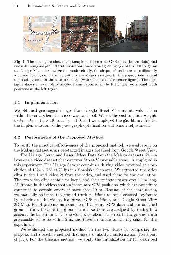
Fig. 4. The left figure shows an example of inaccurate GPS data (brown dots) andmanually assigned ground truth positions (back crosses) on Google Maps. Although weuse Google Maps to visualize the results clearly, the shapes of roads are not sufficientlyaccurate. Our ground truth positions are always assigned in the appropriate lane ofthe road, as seen in the satellite image (white crosses in the center figure). The rightfigure shows an example of a video frame captured at the left of the two ground truthpositions in the left figure.
4.1 Implementation
We obtained geo-tagged images from Google Street View at intervals of 5 mwithin the area where the video was captured. We set the cost function weightsto λ1 = λ2 = 1.0 × 10⁵ and λ3 = 1.0, and we employed the g2o library [26] forthe implementation of the pose graph optimization and bundle adjustment.
4.2 Performance of the Proposed Method
To verify the practical effectiveness of the proposed method, we evaluate it onthe Malaga dataset using geo-tagged images obtained from Google Street View.
The Malaga Stereo and Laser Urban Data Set (the Malaga dataset) [24]—alarge-scale video dataset that captures Street-View-usable areas—is employed inthis experiment. The Malaga dataset contains a driving video captured at a res-olution of 1024 × 768 at 20 fps in a Spanish urban area. We extracted two videoclips (video 1 and video 2) from the video, and used these for the evaluation.The two video clips contain no loops, and their trajectories are over 1 km long.All frames in the videos contain inaccurate GPS positions, which are sometimesconfirmed to contain errors of more than 10 m. Because of the inaccuracies,we manually assigned the ground truth positions to some selected keyframesby referring to the videos, inaccurate GPS positions, and Google Street View3D Map. Fig. 4 presents an example of inaccurate GPS data and our assignedground truth. Because the ground truth positions are assigned by taking intoaccount the lane from which the video was taken, the errors in the ground truthare considered to be within 2 m, and these errors are sufficiently small for thisexperiment.
We evaluated the proposed method on the two videos by comparing theproposal and a baseline method that uses a similarity transformation (like a partof [15]). For the baseline method, we apply the initialization (INIT: described
Scale Drift Correction of Camera Geo-Localization using Geo-Tagged Images 11
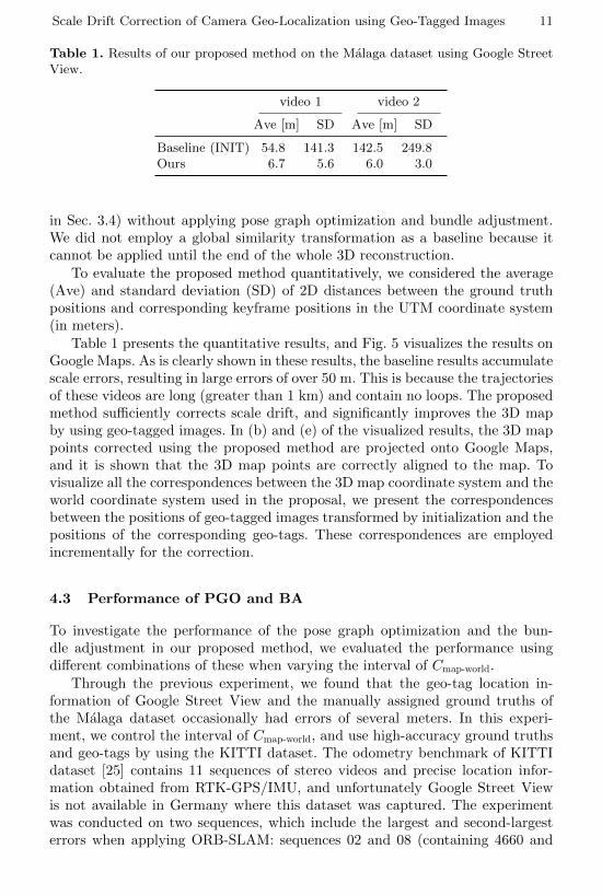
Table 1. Results of our proposed method on the Malaga dataset using Google StreetView.
video 1 video 2
Ave [m] SD Ave [m] SD
Baseline (INIT) 54.8 141.3 142.5 249.8Ours 6.7 5.6 6.0 3.0
in Sec. 3.4) without applying pose graph optimization and bundle adjustment.We did not employ a global similarity transformation as a baseline because itcannot be applied until the end of the whole 3D reconstruction.
To evaluate the proposed method quantitatively, we considered the average(Ave) and standard deviation (SD) of 2D distances between the ground truthpositions and corresponding keyframe positions in the UTM coordinate system(in meters).
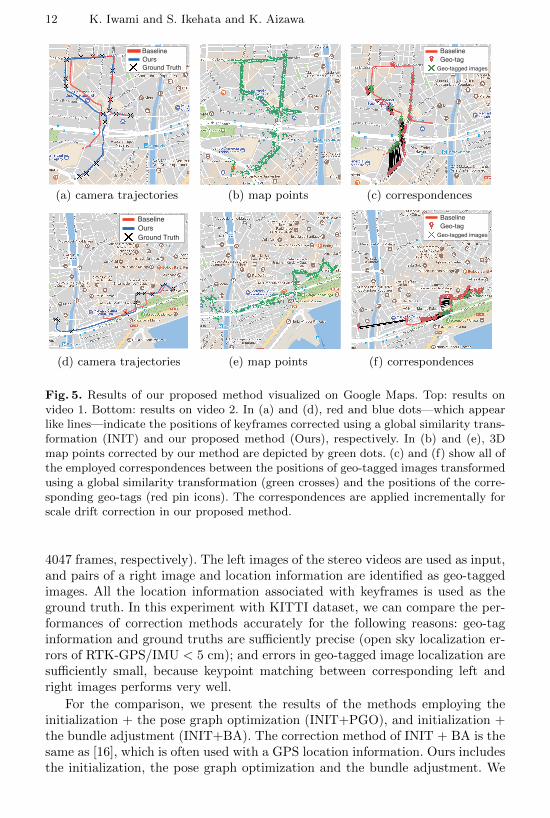
Table 1 presents the quantitative results, and Fig. 5 visualizes the results onGoogle Maps. As is clearly shown in these results, the baseline results accumulatescale errors, resulting in large errors of over 50 m. This is because the trajectoriesof these videos are long (greater than 1 km) and contain no loops. The proposedmethod sufficiently corrects scale drift, and significantly improves the 3D mapby using geo-tagged images. In (b) and (e) of the visualized results, the 3D mappoints corrected using the proposed method are projected onto Google Maps,and it is shown that the 3D map points are correctly aligned to the map. Tovisualize all the correspondences between the 3D map coordinate system and theworld coordinate system used in the proposal, we present the correspondencesbetween the positions of geo-tagged images transformed by initialization and thepositions of the corresponding geo-tags. These correspondences are employedincrementally for the correction.
4.3 Performance of PGO and BA
To investigate the performance of the pose graph optimization and the bun-dle adjustment in our proposed method, we evaluated the performance usingdifferent combinations of these when varying the interval of Cmap-world.
Through the previous experiment, we found that the geo-tag location in-formation of Google Street View and the manually assigned ground truths ofthe Malaga dataset occasionally had errors of several meters. In this experi-ment, we control the interval of Cmap-world, and use high-accuracy ground truthsand geo-tags by using the KITTI dataset. The odometry benchmark of KITTIdataset [25] contains 11 sequences of stereo videos and precise location infor-mation obtained from RTK-GPS/IMU, and unfortunately Google Street Viewis not available in Germany where this dataset was captured. The experimentwas conducted on two sequences, which include the largest and second-largesterrors when applying ORB-SLAM: sequences 02 and 08 (containing 4660 and
12 K. Iwami and S. Ikehata and K. Aizawa
BaselineOursGround Truth
(a) camera trajectories (b) map points
BaselineGeo-tag
Geo-tagged images
(c) correspondences
BaselineOursGround Truth
(d) camera trajectories (e) map points
BaselineGeo-tag
Geo-tagged images
(f) correspondences
Fig. 5. Results of our proposed method visualized on Google Maps. Top: results onvideo 1. Bottom: results on video 2. In (a) and (d), red and blue dots—which appearlike lines—indicate the positions of keyframes corrected using a global similarity trans-formation (INIT) and our proposed method (Ours), respectively. In (b) and (e), 3Dmap points corrected by our method are depicted by green dots. (c) and (f) show all ofthe employed correspondences between the positions of geo-tagged images transformedusing a global similarity transformation (green crosses) and the positions of the corre-sponding geo-tags (red pin icons). The correspondences are applied incrementally forscale drift correction in our proposed method.
4047 frames, respectively). The left images of the stereo videos are used as input,and pairs of a right image and location information are identified as geo-taggedimages. All the location information associated with keyframes is used as theground truth. In this experiment with KITTI dataset, we can compare the per-formances of correction methods accurately for the following reasons: geo-taginformation and ground truths are sufficiently precise (open sky localization er-rors of RTK-GPS/IMU < 5 cm); and errors in geo-tagged image localization aresufficiently small, because keypoint matching between corresponding left andright images performs very well.
For the comparison, we present the results of the methods employing theinitialization + the pose graph optimization (INIT+PGO), and initialization +the bundle adjustment (INIT+BA). The correction method of INIT + BA is thesame as [16], which is often used with a GPS location information. Ours includesthe initialization, the pose graph optimization and the bundle adjustment. We
Scale Drift Correction of Camera Geo-Localization using Geo-Tagged Images 13
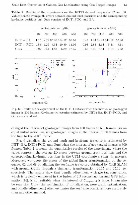
Table 2. Results of the experiments on the KITTI dataset: sequences 02 and 08.Values denote average 2D errors between ground truth positions and the correspondingkeyframe positions [m]. Ours consists of INIT, PGO, and BA.
geotag interval (#02) geotag interval (#08)
100 200 300 400 500 100 200 300 400 500
INIT + BA 1.15 2.22 65.86 164.17 96.66 0.45 1.24 18.43 148.17 52.40
INIT + PGO 4.57 4.26 7.54 10.89 11.96 0.93 2.83 4.64 5.44 9.11
Ours 2.27 2.51 4.87 6.89 12.35 0.50 2.06 2.84 4.19 6.38
sequence 02 sequence 08
Fig. 6. Results of the experiment on the KITTI dataset when the interval of geo-taggedimages is 300 frames. Keyframe trajectories estimated by INIT+BA, INIT+PGO, andOurs are visualized.
changed the interval of geo-tagged images from 100 frames to 500 frames. For anequal initialization, we set geo-tagged images in the interval of 50 frames fromthe first to the 200th frame.
Fig. 6 visualizes the ground truth and keyframe trajectories estimated byINIT+BA, INIT+PGO, and Ours when the interval of geo-tagged images is 300frames. Table 2 presents the quantitative results of the experiment, where thevalues represent the average 2D errors between ground truth positions and thecorresponding keyframe positions in the UTM coordinate system (in meters).Moreover, we report the errors of the global linear transformation on the se-quence 02 and 08 by aligning the keyframe trajectory obtained by ORB-SLAMwith ground truths through a similarity transformation: 20.15 and 25.12, re-spectively. The results show that bundle adjustment with geo-tag constraints,which is typically employed in the fusion of 3D reconstruction and GPS infor-mation [16], is not suitable when the interval of Cmap-world is large. It can alsobe seen that Ours (the combination of initialization, pose graph optimization,and bundle adjustment) often estimates the keyframe positions more accuratelythan any other method.
14 K. Iwami and S. Ikehata and K. Aizawa
sequence 02 sequence 08
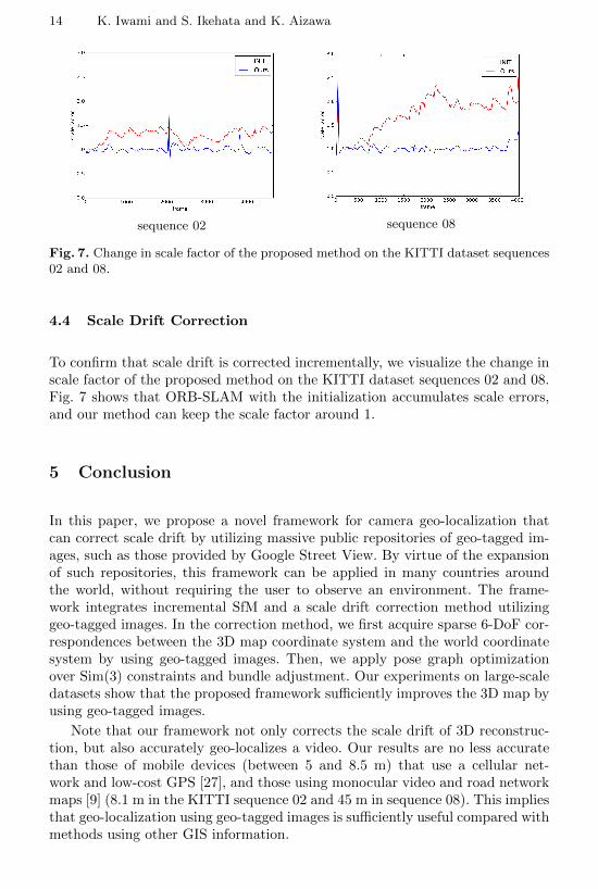
Fig. 7. Change in scale factor of the proposed method on the KITTI dataset sequences02 and 08.
4.4 Scale Drift Correction
To confirm that scale drift is corrected incrementally, we visualize the change inscale factor of the proposed method on the KITTI dataset sequences 02 and 08.Fig. 7 shows that ORB-SLAM with the initialization accumulates scale errors,and our method can keep the scale factor around 1.
5 Conclusion
In this paper, we propose a novel framework for camera geo-localization thatcan correct scale drift by utilizing massive public repositories of geo-tagged im-ages, such as those provided by Google Street View. By virtue of the expansionof such repositories, this framework can be applied in many countries aroundthe world, without requiring the user to observe an environment. The frame-work integrates incremental SfM and a scale drift correction method utilizinggeo-tagged images. In the correction method, we first acquire sparse 6-DoF cor-respondences between the 3D map coordinate system and the world coordinatesystem by using geo-tagged images. Then, we apply pose graph optimizationover Sim(3) constraints and bundle adjustment. Our experiments on large-scaledatasets show that the proposed framework sufficiently improves the 3D map byusing geo-tagged images.
Note that our framework not only corrects the scale drift of 3D reconstruc-tion, but also accurately geo-localizes a video. Our results are no less accuratethan those of mobile devices (between 5 and 8.5 m) that use a cellular net-work and low-cost GPS [27], and those using monocular video and road networkmaps [9] (8.1 m in the KITTI sequence 02 and 45 m in sequence 08). This impliesthat geo-localization using geo-tagged images is sufficiently useful compared withmethods using other GIS information.
Scale Drift Correction of Camera Geo-Localization using Geo-Tagged Images 15
Acknowledgment
This work was partially supported by VTEC laboratories Inc.
References
1. Engel, J., Schops, T., Cremers, D.: LSD-SLAM: Large-scale direct monocular slam.In: European Conference on Computer Vision, Springer (2014) 834–849
2. Mur-Artal, R., Montiel, J.M.M., Tardos, J.D.: ORB-SLAM: a versatile and ac-curate monocular SLAM system. IEEE Transactions on Robotics 31(5) (2015)1147–1163
3. Clemente, L.A., Davison, A.J., Reid, I.D., Neira, J., Tardos, J.D.: Mapping largeloops with a single hand-held camera. In: Robotics: Science and Systems. Volume 2.(2007)
4. Strasdat, H., Montiel, J., Davison, A.J.: Scale drift-aware large scale monocularSLAM. Robotics: Science and Systems VI (2010)
5. Middelberg, S., Sattler, T., Untzelmann, O., Kobbelt, L.: Scalable 6-DoF local-ization on mobile devices. In: European conference on computer vision, Springer(2014) 268–283
6. Caselitz, T., Steder, B., Ruhnke, M., Burgard, W.: Monocular camera localizationin 3d lidar maps. In: Intelligent Robots and Systems (IROS), 2016 IEEE/RSJInternational Conference on, IEEE (2016) 1926–1931
7. Tamaazousti, M., Gay-Bellile, V., Collette, S.N., Bourgeois, S., Dhome, M.: Non-linear refinement of structure from motion reconstruction by taking advantage ofa partial knowledge of the environment. In: Computer Vision and Pattern Recog-nition (CVPR), 2011 IEEE Conference on, IEEE (2011) 3073–3080
8. Untzelmann, O., Sattler, T., Middelberg, S., Kobbelt, L.: A scalable collaborativeonline system for city reconstruction. In: Proceedings of the IEEE InternationalConference on Computer Vision Workshops. (2013) 644–651
9. Brubaker, M.A., Geiger, A., Urtasun, R.: Map-based probabilistic visual self-localization. IEEE transactions on pattern analysis and machine intelligence 38(4)(2016) 652–665
10. : Google street view https://www.google.com/streetview/.11. Klein, G., Murray, D.: Parallel tracking and mapping for small AR workspaces.
In: Mixed and Augmented Reality, 2007. ISMAR 2007. 6th IEEE and ACM Inter-national Symposium on, IEEE (2007) 225–234
12. Lu, F., Milios, E.: Globally consistent range scan alignment for environment map-ping. Autonomous robots 4(4) (1997) 333–349
13. Kaminsky, R.S., Snavely, N., Seitz, S.M., Szeliski, R.: Alignment of 3D point cloudsto overhead images. In: Computer Vision and Pattern Recognition Workshops,2009. CVPR Workshops 2009. IEEE Computer Society Conference on. (2009) 63–70
14. Wendel, A., Irschara, A., Bischof, H.: Automatic alignment of 3D reconstruc-tions using a digital surface model. In: Computer Vision and Pattern RecognitionWorkshops (CVPRW), 2011 IEEE Computer Society Conference on, IEEE (2011)29–36
15. Wang, C.P., Wilson, K., Snavely, N.: Accurate georegistration of point clouds usinggeographic data. In: 3DTV-Conference, 2013 International Conference on. (2013)33–40
16 K. Iwami and S. Ikehata and K. Aizawa
16. Lhuillier, M.: Incremental fusion of structure-from-motion and GPS using con-strained bundle adjustments. IEEE transactions on pattern analysis and machineintelligence 34(12) (2012) 2489–2495
17. Rehder, J., Gupta, K., Nuske, S., Singh, S.: Global pose estimation with limitedgps and long range visual odometry. In: Robotics and Automation (ICRA), 2012IEEE International Conference on. (2012) 627–633
18. Agarwal, P., Burgard, W., Spinello, L.: Metric localization using google streetview. In: Intelligent Robots and Systems (IROS), 2015 IEEE/RSJ InternationalConference on, IEEE (2015) 3111–3118
19. Klingner, B., Martin, D., Roseborough, J.: Street view motion-from-structure-from-motion. In: Proceedings of the IEEE International Conference on ComputerVision. (2013) 953–960
20. Rublee, E., Rabaud, V., Konolige, K., Bradski, G.: ORB: An efficient alternative toSIFT or SURF. In: Computer Vision (ICCV), 2011 IEEE International Conferenceon, IEEE (2011) 2564–2571
21. Majdik, A.L., Albers-Schoenberg, Y., Scaramuzza, D.: Mav urban localizationfrom google street view data. In: Intelligent Robots and Systems (IROS), 2013IEEE/RSJ International Conference on, IEEE (2013) 3979–3986
22. Liu, Z., Marlet, R.: Virtual line descriptor and semi-local matching method forreliable feature correspondence. In: British Machine Vision Conference 2012. (2012)16–1
23. Fischler, M.A., Bolles, R.C.: Random sample consensus: a paradigm for modelfitting with applications to image analysis and automated cartography. Commu-nications of the ACM 24(6) (1981) 381–395
24. Blanco-Claraco, J.L., Moreno-Duenas, F.A., Gonzalez-Jimenez, J.: The malagaurban dataset: High-rate stereo and LiDAR in a realistic urban scenario. TheInternational Journal of Robotics Research 33(2) (2014) 207–214
25. Geiger, A., Lenz, P., Urtasun, R.: Are we ready for autonomous driving? the kittivision benchmark suite. In: Computer Vision and Pattern Recognition (CVPR),2012 IEEE Conference on. (2012) 3354–3361
26. Kummerle, R., Grisetti, G., Strasdat, H., Konolige, K., Burgard, W.: g2o: Ageneral framework for graph optimization. In: Robotics and Automation (ICRA),2011 IEEE International Conference on, IEEE (2011) 3607–3613
27. Zandbergen, P.A., Barbeau, S.J.: Positional accuracy of assisted GPS data fromhigh-sensitivity GPS-enabled mobile phones. The Journal of Navigation 64(3)(2011) 381–399


![OpenStreetSLAM: Global Vehicle Localization Using ...towards performing image based localization using large geo-tagged image corpora acquired from specially equipped plat-forms [3]](https://img.pdfslide.net/doc/110x75/602b02f9e18ddd21da6c4d3e/openstreetslam-global-vehicle-localization-using-towards-performing-image-based.jpg)