Embed Size (px)
Citation preview
GEOCOMP PRODUCTS
Automated Laboratory Testing Systems for Soil, Rock, and Geosynthetics
� Load and strain control
� Multi-language support
� Software and firmware upgrades by internet
� Remote diagnostics and technical support
Introducing our newest Version 5
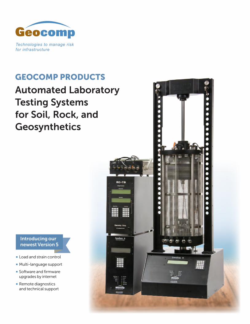
LoadTrac IIIncremental Consolidation ASTM D2435 / D4546, AASHTO T 216
Unconfined Compression ASTM D1663 / D2166, AASHTO T 208
CBR
Geocomp Laboratory Systems are automated universal testing stations
which measure the mechanical properties of soil, rock, and geosynthetics.
These state-of-the-art systems are capable of production work as well as
high-quality research.
Our laboratory testing systems have been successfully used for more than
30 years by government agencies, universities, and private companies
worldwide.
We are pleased to release Version 5 of our systems, a complete upgrade
of electronics and software that provides more features and support of
additional test types.
All components of our systems are designed, developed and supported
by our dedicated, in-house professionals who continuously research
new products and publications to provide upgrades as testing technology
advances.
All systems produced by Geocomp deliver the winning combination
of ease-of-use and technical sophistication.
Unique, technically sophisticated and easy‑to‑use automated systems for reliable testing capabilities
LoadTrac IIIIncremental Consolidation ASTM D2435 / D4546, AASHTO T 216
Unconfined Compression ASTM D1663 / D2166, AASHTO T 208
Products our clients can count on
ON THE COVER:
Geocomp’s RC‑TS: An entirely new
and better approach to Resonant
Column-Torsional Shear Testing Geocomp’s RC-TS pioneers a new approach to
resonant column testing in which rotation of the top
of the specimen is measured very precisely by two
accelerometers and torque is measured directly at
the base. Measured rotation and torque are used to
directly calculate shear modulus and damping. This
system eliminates errors associated with back EMF
factors present in other devices. The theory and design
behind the Geocomp RC-TS is described in a paper
published in the ASTM Geotechnical Testing Journal,
New Approach to Resonant Column Testing.1 This
paper received ASTM’s highest award, the Hogentogler
Award in 2013. The newly revised ASTM standard D4015
includes the new method.
1 Werden, S.K., Drnevich, V.P., Hall, J.R., Hankour, C., Conlee, C.T., and Marr, W.A.
2013. “New Approach to Resonant Column Testing. Geotechnical Testing
Journal, 362, 20120122. ASTM International. doi:10.1520/GTJ20120122]
FlowTrac IIPressure and Volume Control for:
Constant Rate of Strain Consilidation
Triaxial
Stress Path Triaxial
PermeabilityASTM D5084 / D2434
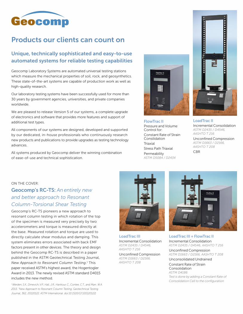
LoadTrac III + FlowTrac IIIncremental Consolidation ASTM D2435 / D4546, AASHTO T 216
Unconfined Compression ASTM D1663 / D2166, AASHTO T 208
Unconsolidated Undrained
Constant Rate of Strain Consolidation ASTM D4186Test is done by adding a Constant Rate of
Consolidation Cell to the configuration
LoadTrac II + Cyclic RMResilient ModulusAASHTO T 294, T 307
SHRP Protocol P46
NCHRP RTT 285
LoadTrac II + FlowTrac IIIncremental Consolidation ASTM D2435 / D4546, AASHTO T 216
Unconfined Compression ASTM D1663 / D2166, AASHTO T 208
Constant Rate of Strain Consolidation ASTM D4186
CBR
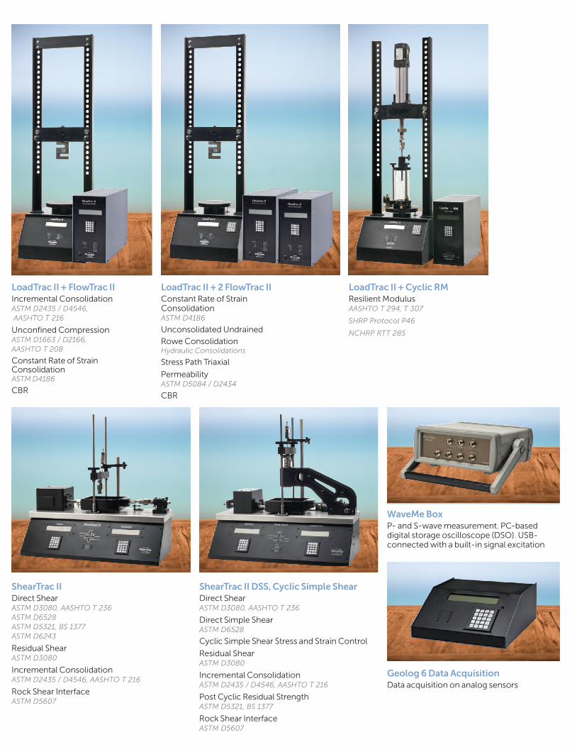
ShearTrac IIDirect ShearASTM D3080, AASHTO T 236ASTM D6528ASTM D5321, BS 1377ASTM D6243
Residual Shear ASTM D3080
Incremental Consolidation ASTM D2435 / D4546, AASHTO T 216
Rock Shear InterfaceASTM D5607
WaveMe BoxP- and S-wave measurement. PC-based digital storage oscilloscope (DSO). USB-connected with a built-in signal excitation
Geolog 6 Data AcquisitionData acquisition on analog sensors
ShearTrac II DSS, Cyclic Simple ShearDirect Shear ASTM D3080, AASHTO T 236
Direct Simple Shear ASTM D6528
Cyclic Simple Shear Stress and Strain Control
Residual Shear ASTM D3080
Incremental Consolidation ASTM D2435 / D4546, AASHTO T 216
Post Cyclic Residual StrengthASTM D5321, BS 1377
Rock Shear InterfaceASTM D5607
LoadTrac II + 2 FlowTrac IIConstant Rate of Strain Consolidation ASTM D4186
Unconsolidated Undrained
Rowe Consolidation Hydraulic Consolidations
Stress Path Triaxial
PermeabilityASTM D5084 / D2434
CBR
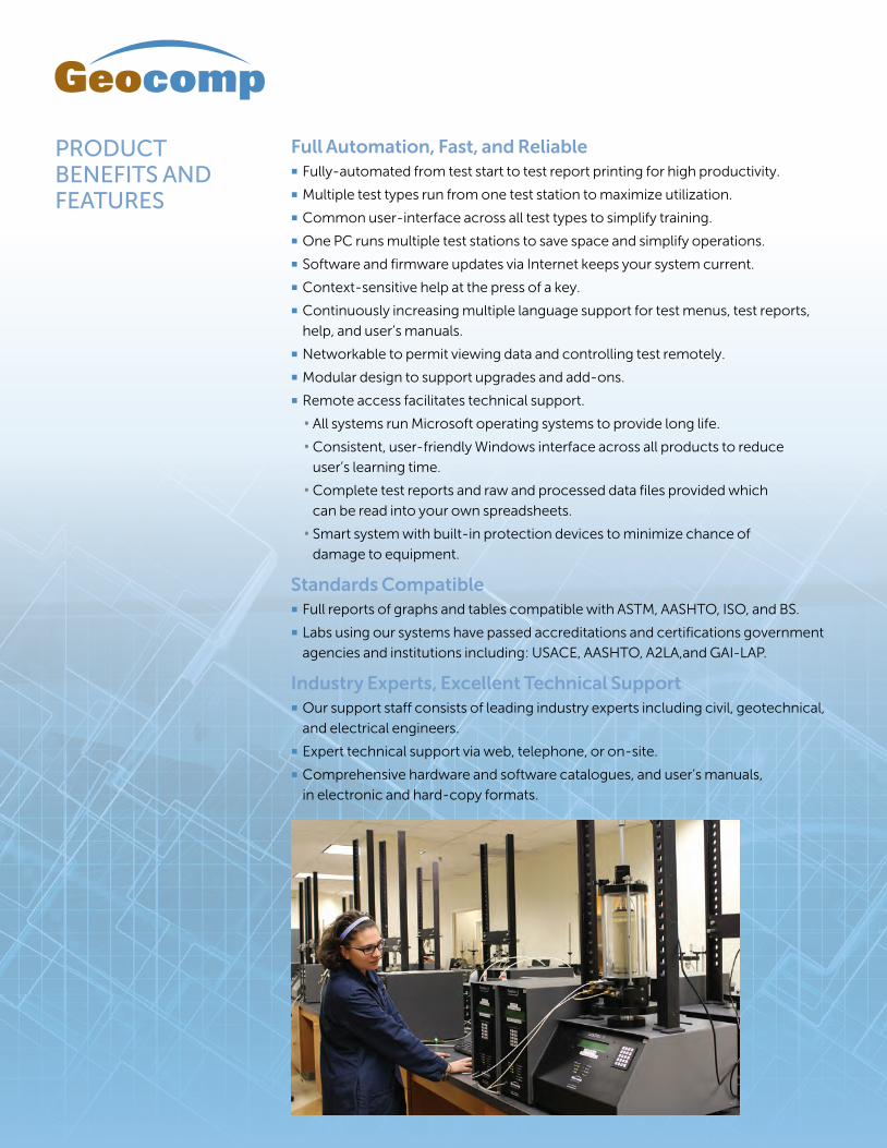
ShearTrac III Large Shear BoxDirect Shear ASTM D3080, AASHTO T 236
Direct Simple Shear ASTM D6528
Interface Shear of Geosynthetics ASTM D5321, BS 1377
Internal Shear of Geosynthetic Clay Liners ASTM D6243
Cyclic ShearTrac III Large Shear BoxDirect Shear ASTM D3080, AASHTO T 236
Direct Simple ShearASTM D5321, BS 1377
Interface Shear of Geosynthetics ASTM D5321, BS 1377
Internal Shear of Geosynthetic Clay Liners ASTM D6243
Cyclic Direct Simple Shear of Soils
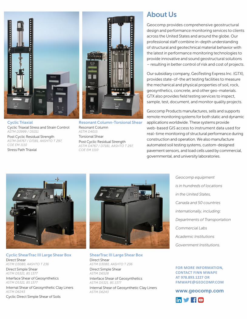
Resonant Column‑Torsional ShearResonant Column ASTM D4015
Torsional Shear
Post Cyclic Residual Strength ASTM D4767 / D7181, AASHTO T 297, COE EM 1110
Cyclic Triaxial Cyclic Triaxial Stress and Strain Control ASTM D3999 / D5311
Post Cyclic Residual Strength ASTM D4767 / D7181, AASHTO T 297, COE EM 1110
Stress Path Triaxial
About UsGeocomp provides comprehensive geostructural
design and performance monitoring services to clients
across the United States and around the globe. Our
professional staff combine in-depth understanding
of structural and geotechnical material behavior with
the latest in performance monitoring technologies to
provide innovative and sound geostructural solutions
– resulting in better control of risk and cost of projects.
Our subsidiary company, GeoTesting Express Inc. (GTX),
provides state-of-the art testing facilities to measure
the mechanical and physical properties of soil, rock,
geosynthetics, concrete, and other geo-materials.
GTX also provides field testing services to inspect,
sample, test, document, and monitor quality projects.
Geocomp Products manufactures, sells and supports
remote monitoring systems for both static and dynamic
applications worldwide. These systems provide
web-based GIS access to instrument data used for
real-time monitoring of structural performance during
construction and operation. We also manufacture
automated soil testing systems, custom-designed
pavement sensors, and load cells used by commercial,
governmental, and university laboratories.
Geocomp equipment
is in hundreds of locations
in the United States,
Canada and 50 countries
internationally, including:
Departments of Transportation
Commercial Labs
Academic Institutions
Government Institutions.
FOR MORE INFORMATION, CONTACT FINN MWAPE AT 978.893.1227 OR [email protected]
Full Automation, Fast, and Reliable � Fully-automated from test start to test report printing for high productivity.
� Multiple test types run from one test station to maximize utilization.
� Common user-interface across all test types to simplify training.
� One PC runs multiple test stations to save space and simplify operations.
� Software and firmware updates via Internet keeps your system current.
� Context-sensitive help at the press of a key.
� Continuously increasing multiple language support for test menus, test reports,
help, and user’s manuals.
� Networkable to permit viewing data and controlling test remotely.
� Modular design to support upgrades and add-ons.
� Remote access facilitates technical support.
• All systems run Microsoft operating systems to provide long life.
• Consistent, user-friendly Windows interface across all products to reduce
user’s learning time.
• Complete test reports and raw and processed data files provided which
can be read into your own spreadsheets.
• Smart system with built-in protection devices to minimize chance of
damage to equipment.
Standards Compatible � Full reports of graphs and tables compatible with ASTM, AASHTO, ISO, and BS.
� Labs using our systems have passed accreditations and certifications government
agencies and institutions including: USACE, AASHTO, A2LA,and GAI-LAP.
Industry Experts, Excellent Technical Support � Our support staff consists of leading industry experts including civil, geotechnical,
and electrical engineers.
� Expert technical support via web, telephone, or on-site.
� Comprehensive hardware and software catalogues, and user’s manuals,
in electronic and hard-copy formats.
PRODUCT BENEFITS AND FEATURES

We design and manufacture automated laboratory testing systems and
remote monitoring devices. We focus on creating products
that help our clients accomplish their goals efficiently and quickly,
whether it be in teaching, research, commercial, or other
applications. We design our automated testing systems to help the user
perform tests efficiently and quickly and produce high-quality
results. Our remote monitoring systems are robust, versatile, and are easy
to use in varying environmental settings. We serve numerous clients in over
50 countries. Join our many satisfied customers and make us your trusted
source for remote monitoring equipment and automated laboratory testing
systems.
Contact us to be added to our orders list.
GEOCOMP PRODUCTS
A u t o m a t e d Tr i a x i a l , R e s i l i e n t M o d u l u s ,a n d R e s o n a n t C o l u m n - T o r s i o n a l S y s t e m s
Automated Triaxial Stress Path
Triaxial
Cyclic Triaxial
Resilient Modulus
Resonant Column - Torsional Shear
Benefits and Features• Chooseloadcapacitytofituser
needsfrom45and90kN(10,000and20,000lbs.)models
• Totalautomation,control,datacollectionandreportingoftestresults
• Preparetablesandplotsofreportqualitywithinminutesofcompletingatest
• Geo-NETcompatibilityletsunitbeaccessedandcontrolledoveracomputernetwork
• Generatecolumnsofdataforeasyreductionusingyourownspreadsheetsoftware
• Accuratedisplacementratecontrolfrom0.00003to35mmperminute(0.000001to1.3inchesperminute)
• StandalonethroughfrontkeypadandLCDmenucapability
Applicable Test Standards
• ASTMD4767/D7181/D2850
• AASHTOT297
• COEEM1110ConsolidatedUndrainedCompression/ExtensionTests,ConsolidatedDrainedCompression/Extensiontests,StressPathTests
• BS(BritishStandard)
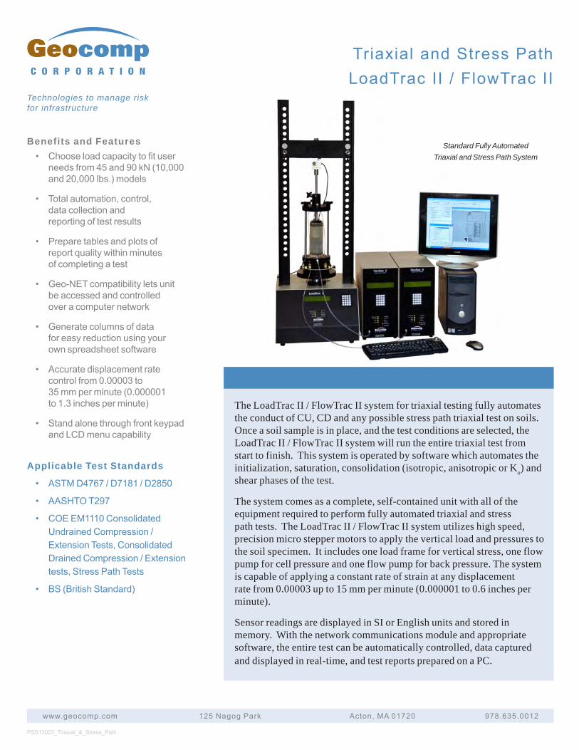
The LoadTrac II / FlowTrac II system for triaxial testing fully automates the conduct of CU, CD and any possible stress path triaxial test on soils. Once a soil sample is in place, and the test conditions are selected, the LoadTrac II / FlowTrac II system will run the entire triaxial test from start to finish. This system is operated by software which automates the initialization, saturation, consolidation (isotropic, anisotropic or Ko) and shear phases of the test.
The system comes as a complete, self-contained unit with all of the equipment required to perform fully automated triaxial and stress path tests. The LoadTrac II / FlowTrac II system utilizes high speed, precision micro stepper motors to apply the vertical load and pressures to the soil specimen. It includes one load frame for vertical stress, one flow pump for cell pressure and one flow pump for back pressure. The system is capable of applying a constant rate of strain at any displacement rate from 0.00003 up to 15 mm per minute (0.000001 to 0.6 inches per minute).
Sensor readings are displayed in SI or English units and stored in memory. With the network communications module and appropriate software, the entire test can be automatically controlled, data captured and displayed in real-time, and test reports prepared on a PC.
PSS13023_Triaxial_&_Stress_Path
www.geocomp.com 125NagogPark Acton,MA01720 978.635.0012
C O R P O R A T I O N
Technologies to manage risk for infrastructure
Standard Fully Automated Triaxial and Stress Path System
TriaxialandStressPathLoadTracII/FlowTracII
TriaxialandStressPathLoadTracII/FlowTracII
www.geocomp.com 125NagogPark Acton,MA01720 978.635.0012
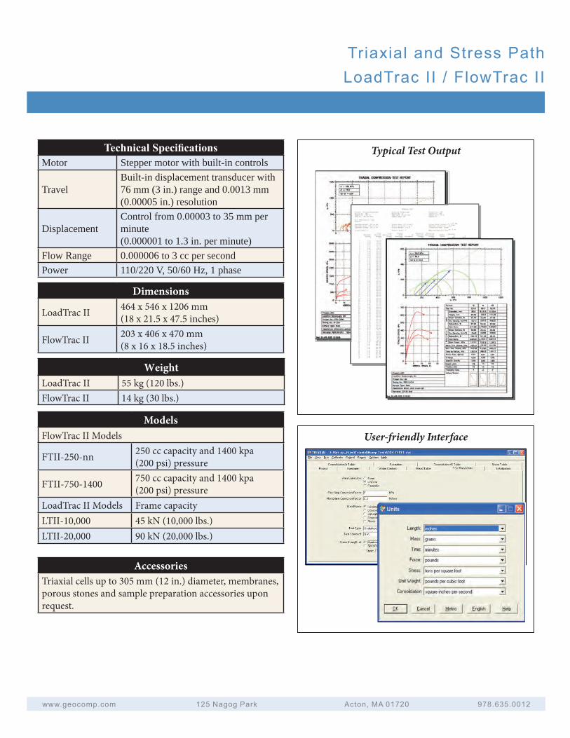
Technical Specifi cationsMotor Stepper motor with built-in controls
TravelBuilt-in displacement transducer with 76 mm (3 in.) range and 0.0013 mm (0.00005 in.) resolution
DisplacementControl from 0.00003 to 35 mm per minute (0.000001 to 1.3 in. per minute)
Flow Range 0.000006 to 3 cc per secondPower 110/220 V, 50/60 Hz, 1 phase
Typical Test Output
User-friendly InterfaceModels
FlowTrac II Models
FTII-250-nn 250 cc capacity and 1400 kpa (200 psi) pressure
FTII-750-1400 750 cc capacity and 1400 kpa (200 psi) pressure
LoadTrac II Models Frame capacityLTII-10,000 45 kN (10,000 lbs.)LTII-20,000 90 kN (20,000 lbs.)
AccessoriesTriaxial cells up to 305 mm (12 in.) diameter, membranes, porous stones and sample preparation accessories upon request.
Dimensions
LoadTrac II 464 x 546 x 1206 mm(18 x 21.5 x 47.5 inches)
FlowTrac II 203 x 406 x 470 mm(8 x 16 x 18.5 inches)
WeightLoadTrac II 55 kg (120 lbs.)FlowTrac II 14 kg (30 lbs.)
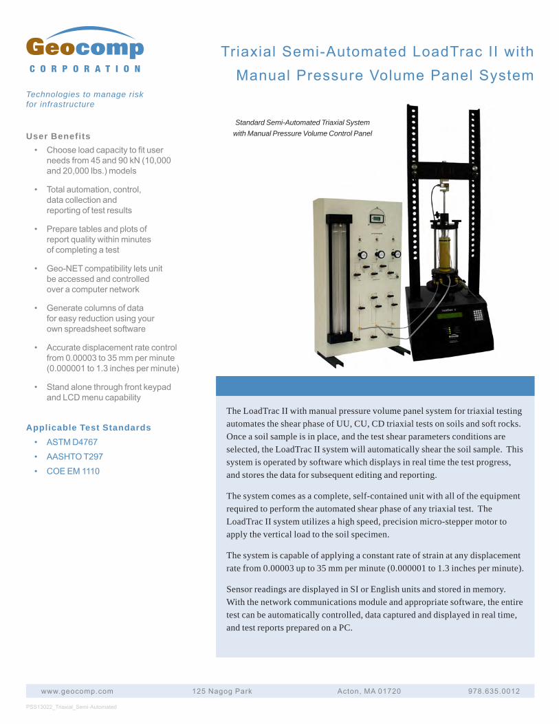
User Benefits• Chooseloadcapacitytofituser
needsfrom45and90kN(10,000and20,000lbs.)models
• Totalautomation,control,datacollectionandreportingoftestresults
• Preparetablesandplotsofreportqualitywithinminutesofcompletingatest
• Geo-NETcompatibilityletsunitbeaccessedandcontrolledoveracomputernetwork
• Generatecolumnsofdataforeasyreductionusingyourownspreadsheetsoftware
• Accuratedisplacementratecontrolfrom0.00003to35mmperminute(0.000001to1.3inchesperminute)
• StandalonethroughfrontkeypadandLCDmenucapability
Applicable Test Standards• ASTMD4767
• AASHTOT297
• COEEM1110
The LoadTrac II with manual pressure volume panel system for triaxial testing automates the shear phase of UU, CU, CD triaxial tests on soils and soft rocks. Once a soil sample is in place, and the test shear parameters conditions are selected, the LoadTrac II system will automatically shear the soil sample. This system is operated by software which displays in real time the test progress, and stores the data for subsequent editing and reporting.
The system comes as a complete, self-contained unit with all of the equipment required to perform the automated shear phase of any triaxial test. The LoadTrac II system utilizes a high speed, precision micro-stepper motor to apply the vertical load to the soil specimen.
The system is capable of applying a constant rate of strain at any displacement rate from 0.00003 up to 35 mm per minute (0.000001 to 1.3 inches per minute).
Sensor readings are displayed in SI or English units and stored in memory. With the network communications module and appropriate software, the entire test can be automatically controlled, data captured and displayed in real time, and test reports prepared on a PC.
PSS13022_Triaxial_Semi-Automated
www.geocomp.com 125NagogPark Acton,MA01720 978.635.0012
C O R P O R A T I O N
Technologies to manage risk for infrastructure
Standard Semi-Automated Triaxial System with Manual Pressure Volume Control Panel
TriaxialSemi-AutomatedLoadTracIIwithManualPressureVolumePanelSystem
TriaxialSemi-AutomatedLoadTracIIwithManualPressureVolumePanelSystem
www.geocomp.com 125NagogPark Acton,MA01720 978.635.0012
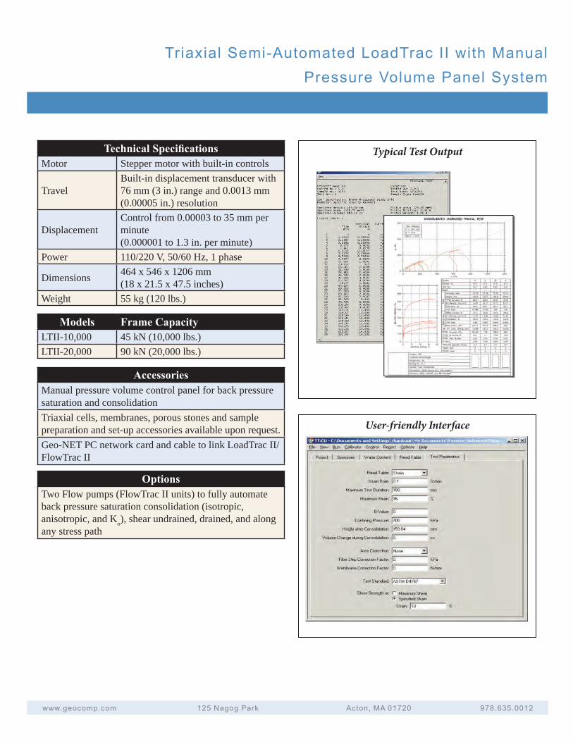
Technical Specifi cationsMotor Stepper motor with built-in controls
TravelBuilt-in displacement transducer with 76 mm (3 in.) range and 0.0013 mm (0.00005 in.) resolution
DisplacementControl from 0.00003 to 35 mm per minute (0.000001 to 1.3 in. per minute)
Power 110/220 V, 50/60 Hz, 1 phase
Dimensions 464 x 546 x 1206 mm(18 x 21.5 x 47.5 inches)
Weight 55 kg (120 lbs.)
Typical Test Output
User-friendly Interface
Models Frame CapacityLTII-10,000 45 kN (10,000 lbs.)LTII-20,000 90 kN (20,000 lbs.)
AccessoriesManual pressure volume control panel for back pressure saturation and consolidationTriaxial cells, membranes, porous stones and sample preparation and set-up accessories available upon request.Geo-NET PC network card and cable to link LoadTrac II/FlowTrac II
OptionsTwo Flow pumps (FlowTrac II units) to fully automate back pressure saturation consolidation (isotropic, anisotropic, and Ko), shear undrained, drained, and along any stress path
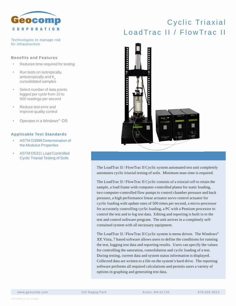
The LoadTrac II / FlowTrac II Cyclic system automated test unit completely automates cyclic triaxial testing of soils. Minimum man-time is required.
The LoadTrac II / FlowTrac II Cyclic consists of a triaxial cell to retain the sample, a load frame with computer-controlled platen for static loading, two computer-controlled flow pumps to control chamber pressure and back pressure, a high performance linear actuator servo control actuator for cyclic loading with update rates of 500 times per second, a micro-processor for accurately controlling cyclic loading, a PC with a Pentium processor to control the test and to log test data. Editing and reporting is built in to the test and control software program. The unit arrives in a completely self-contained system with all necessary equipment.
The LoadTrac II / FlowTrac II Cyclic system is menu driven. The Windows® XP, Vista, 7 based software allows users to define the conditions for running the test, logging test data and reporting results. Users can specify the values for controlling the saturation, consolidation and cyclic loading of a test. During testing, current data and system status information is displayed. Collected data are written to a file on the system’s hard drive. The reporting software performs all required calculations and permits users a variety of options in graphing and generating test data.
PSS13008_Cyclic_Triaxial
www.geocomp.com 125 Nagog Park Acton, MA 01720 978.635.0012
C O R P O R A T I O N
Technologies to manage risk for infrastructure
Cyc l i c Tr iax ia l LoadTrac I I / F lowTrac I I
Benefits and Features• Reduces time required for testing
• Run tests on isotropically,anisotropically and Koconsolidated samples
• Select number of data pointslogged per cycle from 10 to500 readings per second
• Reduce test error andimprove quality control
• Operates in a Windows® OS
Applicable Test Standards• ASTM D3999 Determination of
the Modulus Properties
• ASTM D5311 Load ControlledCyclic Triaxial Testing of Soils
Cyc l i c Tr iax ia l LoadTrac I I / F lowTrac I I
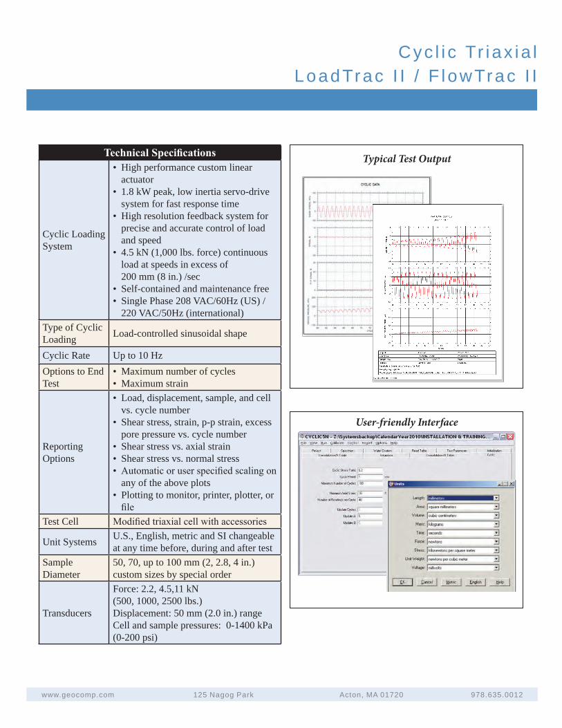
Technical Specifi cations
Cyclic Loading System
• High performance custom linearactuator
• 1.8 kW peak, low inertia servo-drivesystem for fast response time
• High resolution feedback system forprecise and accurate control of loadand speed
• 4.5 kN (1,000 lbs. force) continuousload at speeds in excess of200 mm (8 in.) /sec
• Self-contained and maintenance free• Single Phase 208 VAC/60Hz (US) /
220 VAC/50Hz (international)Type of Cyclic Loading Load-controlled sinusoidal shape
Cyclic Rate Up to 10 HzOptions to End Test
• Maximum number of cycles• Maximum strain
Reporting Options
• Load, displacement, sample, and cellvs. cycle number
• Shear stress, strain, p-p strain, excesspore pressure vs. cycle number
• Shear stress vs. axial strain• Shear stress vs. normal stress• Automatic or user specifi ed scaling on
any of the above plots• Plotting to monitor, printer, plotter, or
fi leTest Cell Modifi ed triaxial cell with accessories
Unit Systems U.S., English, metric and SI changeableat any time before, during and after test
Sample Diameter
50, 70, up to 100 mm (2, 2.8, 4 in.)custom sizes by special order
Transducers
Force: 2.2, 4.5,11 kN (500, 1000, 2500 lbs.)Displacement: 50 mm (2.0 in.) rangeCell and sample pressures: 0-1400 kPa (0-200 psi)
User-friendly Interface
www.geocomp.com 125 Nagog Park Acton, MA 01720 978.635.0012
Typical Test Output

Geocomp’s load frame does more than just Resilient Modulus testing.
With software and accessories, the fol lowing tests can also be done:
• California bearing ratio
• Compression testing of weakrocks and cement mixtures
• Constant rate of strainconsolidation testing
• Cyclic triaxial testing
• Incremental consolidation
• Triaxial testing
• Unconfined compression
Our system generates data in a variety of formats, so users get the most use out of the data.Options include:
• A complete final test report withall appropriate calculations on thedata and constitutive relationshipsbased on Publication No.FHWA-RD-97-083
• A text file of raw data and a text fileof data in engineering units
Either can be easily loaded into a spreadsheet for further data analysis.
Geocomp’s LoadTrac II Resilient Modulus unit fully automates resilient modulus tests on base / subbase / subgrade materials. The LoadTrac II meets or exceeds all specifications for Resilient Modulus Testing of Base / Subbase / Subgrade Materials by AASHTO T294 / T307, SHRP Protocol P46 and NCHRP Report 285. It minimizes man time during testing and offers a versatile platform for performing additional geotechnical tests. The LoadTrac II performs resilient modulus tests from beginning to end according to the latest AASHTO standards without human intervention.
Resilient modulus testing is a complicated test in which the stiffness of the sample changes with loading. Since the performance of cyclic loading systems depends on the stiffness of the sample, most systems fail to apply the correct load throughout the test. Our system uses real-time adjustment of a PID controller to adjust the system control parameters as the stiffness of the specimen changes. This feature permits our system to apply an accurate load from the beginning to the end of the test.
Training time is short, as most people are familiar with the Windows® operating environment. Users can configure a wide variety of graphical screens to display the test results including tabular and graphical display of channel values with time, graphical display of stresses, strains, displacements and resilient modulus values.
PSS13016_Resilient_Modulus
www.geocomp.com 125 Nagog Park Acton, MA 01720 978.635.0012
C O R P O R A T I O N
Technologies to manage risk for infrastructure
Res i l i en t Modu lusLoadTrac I I -RM
Res i l i en t Modu lusLoadTrac I I -RM
www.geocomp.com 125 Nagog Park Acton, MA 01720 978.635.0012
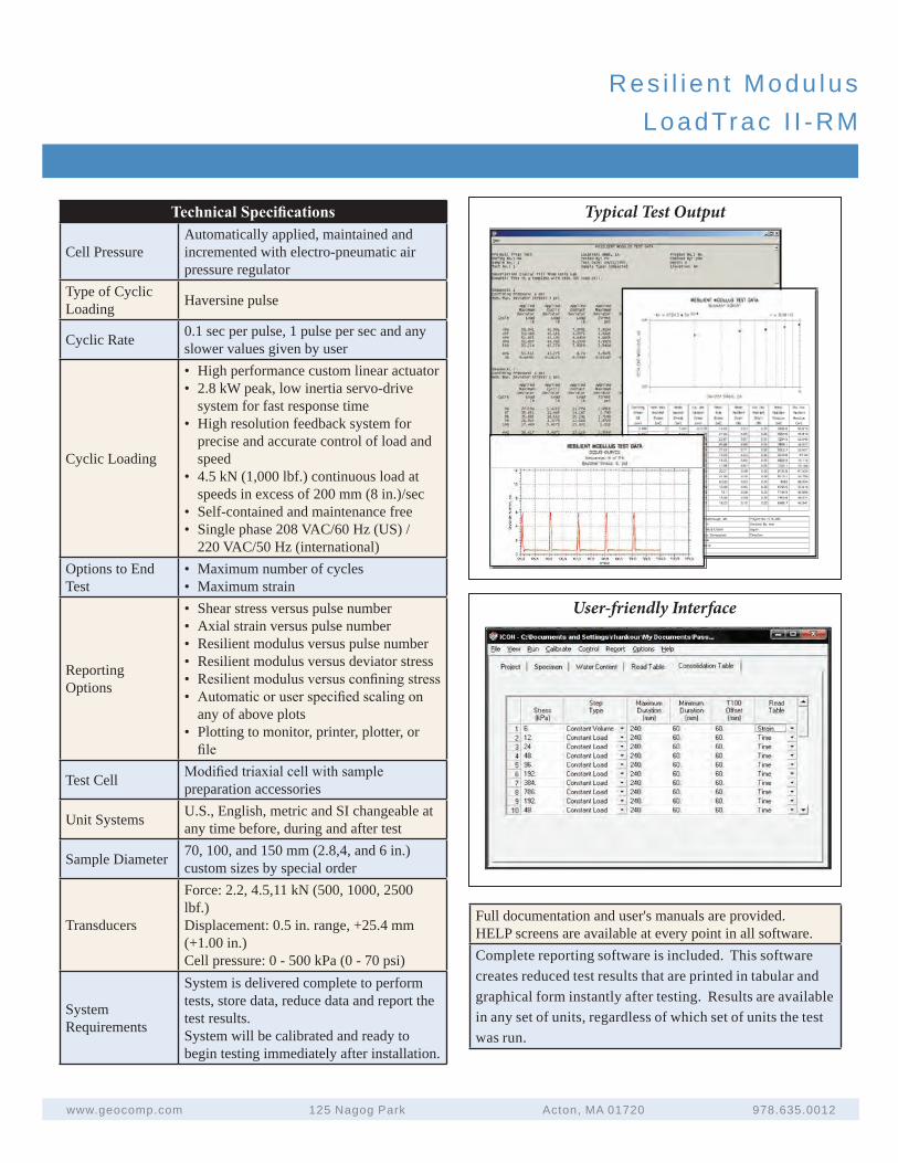
Technical Specifi cations
Cell PressureAutomatically applied, maintained and incremented with electro-pneumatic air pressure regulator
Type of Cyclic Loading Haversine pulse
Cyclic Rate 0.1 sec per pulse, 1 pulse per sec and any slower values given by user
Cyclic Loading
• High performance custom linear actuator• 2.8 kW peak, low inertia servo-drive
system for fast response time• High resolution feedback system for
precise and accurate control of load andspeed
• 4.5 kN (1,000 lbf.) continuous load atspeeds in excess of 200 mm (8 in.)/sec
• Self-contained and maintenance free• Single phase 208 VAC/60 Hz (US) /
220 VAC/50 Hz (international)Options to End Test
• Maximum number of cycles• Maximum strain
Reporting Options
• Shear stress versus pulse number• Axial strain versus pulse number• Resilient modulus versus pulse number• Resilient modulus versus deviator stress• Resilient modulus versus confi ning stress• Automatic or user specifi ed scaling on
any of above plots• Plotting to monitor, printer, plotter, or
fi le
Test Cell Modifi ed triaxial cell with sample preparation accessories
Unit Systems U.S., English, metric and SI changeable atany time before, during and after test
Sample Diameter 70, 100, and 150 mm (2.8,4, and 6 in.)custom sizes by special order
Transducers
Force: 2.2, 4.5,11 kN (500, 1000, 2500 lbf.)Displacement: 0.5 in. range, +25.4 mm(+1.00 in.)Cell pressure: 0 - 500 kPa (0 - 70 psi)
System Requirements
System is delivered complete to perform tests, store data, reduce data and report the test results. System will be calibrated and ready to begin testing immediately after installation.
Typical Test Output
User-friendly Interface
Full documentation and user's manuals are provided. HELP screens are available at every point in all software.Complete reporting software is included. This software creates reduced test results that are printed in tabular and graphical form instantly after testing. Results are available in any set of units, regardless of which set of units the test was run.
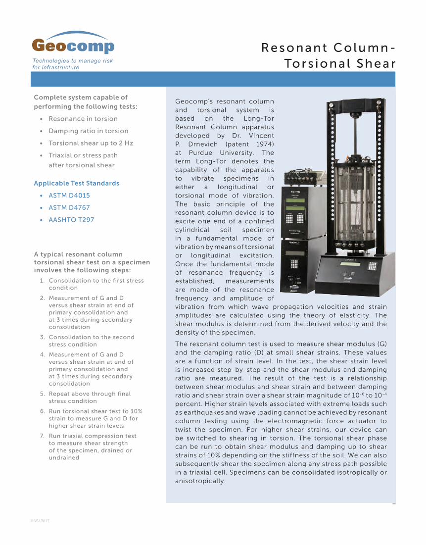
Complete system capable of
performing the following tests:
• Resonance in torsion
• Damping ratio in torsion
• Torsional shear up to 2 Hz
• Triaxial or stress path
after torsional shear
Applicable Test Standards
• ASTM D4015
• ASTM D4767
• AASHTO T297
PSS13017
A typical resonant column torsional shear test on a specimen involves the following steps:
1. Consolidation to the first stresscondition
2. Measurement of G and Dversus shear strain at end ofprimary consolidation andat 3 times during secondaryconsolidation
3. Consolidation to the secondstress condition
4. Measurement of G and Dversus shear strain at end ofprimary consolidation andat 3 times during secondaryconsolidation
5. Repeat above through finalstress condition
6. Run torsional shear test to 10%strain to measure G and D forhigher shear strain levels
7. Run triaxial compression testto measure shear strengthof the specimen, drained orundrained
R e s o n a n t C o l u m n -To r s i o n a l S h e a r
Geocomp’s resonant column and torsional system is based on the Long-Tor Resonant Column apparatus developed by Dr. Vincent P. Drnevich (patent 1974)at Purdue University. Theterm Long-Tor denotes thecapability of the apparatusto vibrate specimens ineither a longitudinal ortorsional mode of vibration.The basic principle of theresonant column device is toexcite one end of a confinedcylindrical soil specimenin a fundamental mode ofvibration by means of torsional or longitudinal excitation.Once the fundamental modeof resonance frequency isestablished, measurementsare made of the resonancefrequency and amplitude ofvibration from which wave propagation velocities and strainamplitudes are calculated using the theory of elasticity. Theshear modulus is determined from the derived velocity and thedensity of the specimen.
The resonant column test is used to measure shear modulus (G) and the damping ratio (D) at small shear strains. These values are a function of strain level. In the test, the shear strain level is increased step-by-step and the shear modulus and damping ratio are measured. The result of the test is a relationship between shear modulus and shear strain and between damping ratio and shear strain over a shear strain magnitude of 10-6 to 10-4 percent. Higher strain levels associated with extreme loads such as earthquakes and wave loading cannot be achieved by resonant column testing using the electromagnetic force actuator to twist the specimen. For higher shear strains, our device can be switched to shearing in torsion. The torsional shear phase can be run to obtain shear modulus and damping up to shear strains of 10% depending on the stiffness of the soil. We can also subsequently shear the specimen along any stress path possible in a triaxial cell. Specimens can be consolidated isotropically or anisotropically.
B o s t o n A t l a n t a C h i c a g o L o s A n g e l e s N e w Yo r k
R e s o n a n t C o l u m n -To r s i o n a l S h e a r
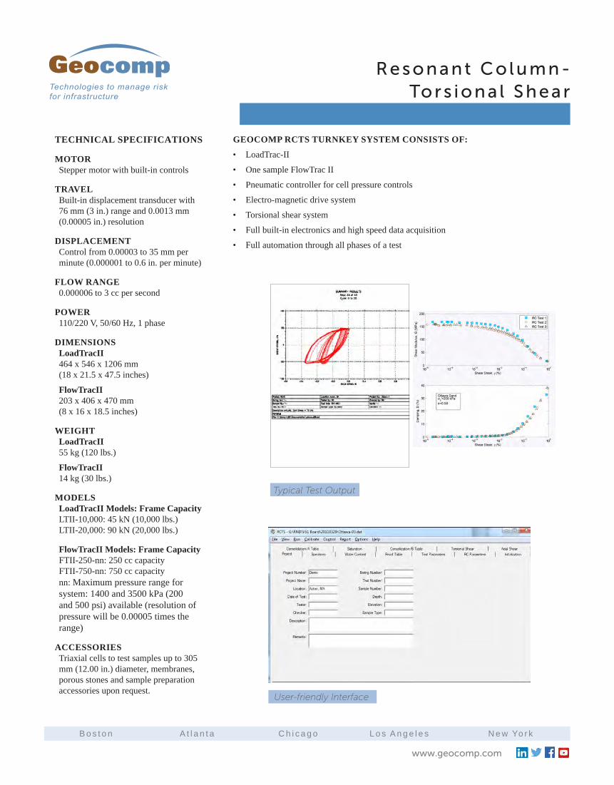
TECHNICAL SPECIFICATIONS
MOTORStepper motor with built-in controls
TRAVELBuilt-in displacement transducer with 76 mm (3 in.) range and 0.0013 mm (0.00005 in.) resolution
DISPLACEMENTControl from 0.00003 to 35 mm per minute (0.000001 to 0.6 in. per minute)
FLOW RANGE0.000006 to 3 cc per second
POWER110/220 V, 50/60 Hz, 1 phase
DIMENSIONSLoadTracII 464 x 546 x 1206 mm (18 x 21.5 x 47.5 inches)
FlowTracII 203 x 406 x 470 mm (8 x 16 x 18.5 inches)
WEIGHTLoadTracII 55 kg (120 lbs.)
FlowTracII 14 kg (30 lbs.)
MODELSLoadTracII Models: Frame Capacity LTII-10,000: 45 kN (10,000 lbs.) LTII-20,000: 90 kN (20,000 lbs.)
FlowTracII Models: Frame Capacity FTII-250-nn: 250 cc capacity FTII-750-nn: 750 cc capacity nn: Maximum pressure range for system: 1400 and 3500 kPa (200 and 500 psi) available (resolution of pressure will be 0.00005 times the range)
ACCESSORIESTriaxial cells to test samples up to 305 mm (12.00 in.) diameter, membranes, porous stones and sample preparation accessories upon request.
GEOCOMP RCTS TURNKEY SYSTEM CONSISTS OF:
• LoadTrac-II
• One sample FlowTrac II
• Pneumatic controller for cell pressure controls
• Electro-magnetic drive system
• Torsional shear system
• Full built-in electronics and high speed data acquisition
• Full automation through all phases of a test
Typical Test Output
User-friendly Interface
www.geocomp.com
A u t o m a t e d C o n s o l i d a t i o n S y s t e m s
CV15004
Incremental Consolidation – Loadtrac III
Incremental Consolidation – Loadtrac II
Controlled-Strain Loading Consolidation - LoadTrac III
Controlled-Strain Loading Consolidation - LoadTrac II
Rowe Consolidation
Benefits and Features
• Totalautomationofdatacollectionandreportingoftestresults
• Preparetablesandplotsofreportqualitywithinminutesofcompletingatest
• Generatecolumnsofdataforeasyreductionusingyourownspreadsheetsoftware
• AbilitytoaccessandcontroltheunitoveracomputernetworkusingGeo-Netoption
Applicable Test Standards
• ASTMD2435IncrementalConsolidation
• AASHTOT216IncrementalConsolidation
• ASTMD4546One-DimensionalSwellorSettlementPotentialofCohesiveSoils
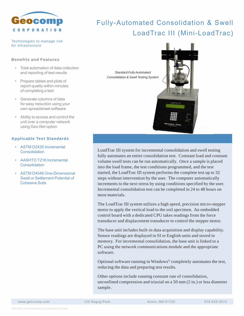
LoadTrac III system for incremental consolidation and swell testing fully automates an entire consolidation test. Constant load and constant volume swell tests can be run automatically. Once a sample is placed into the load frame, the test conditions programmed, and the test started, the LoadTrac III system performs the complete test up to 32 steps without intervention by the user. The computer automatically increments to the next stress by using conditions specified by the user. Incremental consolidation test can be completed in 24 to 48 hours on most materials.
The LoadTrac III system utilizes a high speed, precision micro-stepper motor to apply the vertical load to the soil specimen. An embedded control board with a dedicated CPU takes readings from the force transducer and displacement transducer to control the stepper motor.
The base unit includes built-in data acquisition and display capability. Sensor readings are displayed in SI or English units and stored in memory. For incremental consolidation, the base unit is linked to a PC using the network communications module and the appropriate software.
Optional software running in Windows® completely automates the test, reducing the data and preparing test results.
Other options include running constant rate of consolidation, unconfined compression and triaxial on a 50 mm (2 in.) or less diameter sample.
PSS13015_Fully-Automated_Consolidation_&_Swell
www.geocomp.com 125NagogPark Acton,MA01720 978.635.0012
C O R P O R A T I O N
Technologies to manage risk for infrastructure
Standard Fully Automated Consolidation & Swell Testing System
Fully-AutomatedConsolidation&SwellLoadTracIII(Mini-LoadTrac)
Fully-AutomatedConsolidation&SwellLoadTracIII(Mini-LoadTrac)
www.geocomp.com 125NagogPark Acton,MA01720 978.635.0012
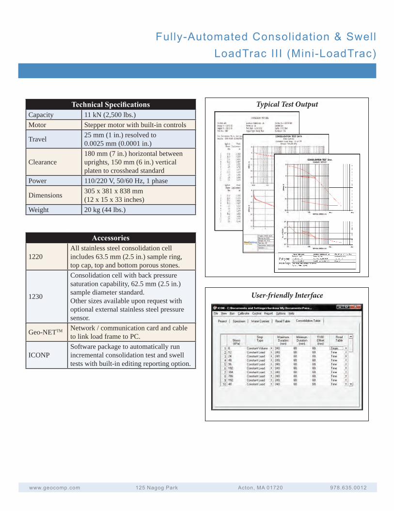
Technical Specifi cationsCapacity 11 kN (2,500 lbs.)Motor Stepper motor with built-in controls
Travel 25 mm (1 in.) resolved to 0.0025 mm (0.0001 in.)
Clearance180 mm (7 in.) horizontal between uprights, 150 mm (6 in.) vertical platen to crosshead standard
Power 110/220 V, 50/60 Hz, 1 phase
Dimensions 305 x 381 x 838 mm(12 x 15 x 33 inches)
Weight 20 kg (44 lbs.)
Typical Test Output
User-friendly Interface
Accessories
1220All stainless steel consolidation cell includes 63.5 mm (2.5 in.) sample ring, top cap, top and bottom porous stones.
1230
Consolidation cell with back pressure saturation capability, 62.5 mm (2.5 in.) sample diameter standard. Other sizes available upon request with optional external stainless steel pressure sensor.
Geo-NETTM Network / communication card and cable to link load frame to PC.
ICONPSoftware package to automatically run incremental consolidation test and swell tests with built-in editing reporting option.
Benefits and Features• Choosecapacitytofituser
needsfrom45to90kN(10,000to20,000lbs.)models
• Totalautomation,control,datacollectionandreportingoftestresults
• Preparetablesandplotsofreportqualitywithinminutesofcompletingatest
• Geo-NETcompatibilityletsunitbeaccessedandcontrolledoveracomputernetwork
• Generatecolumnsofdataforeasyreductionusingyourownspreadsheetsoftware
Applicable Test Standards• ASTMD2435Incremental
Consolidation
• AASHTOT216IncrementalConsolidation
• ASTMD4546OneDimensionalSwellorSettlementPotentialofCohesiveSoils
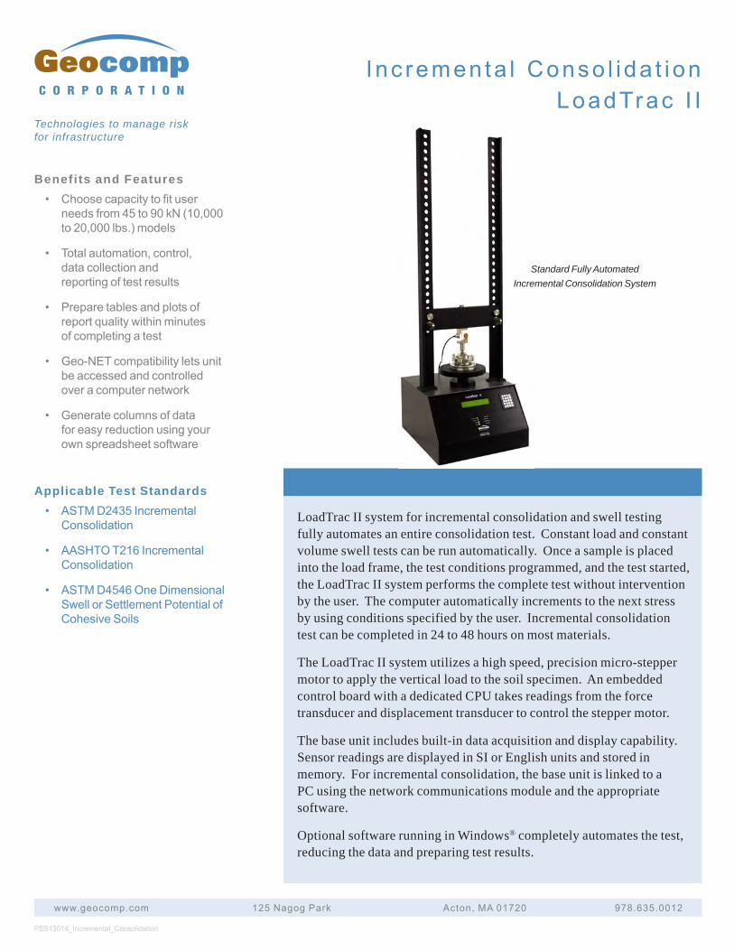
LoadTrac II system for incremental consolidation and swell testing fully automates an entire consolidation test. Constant load and constant volume swell tests can be run automatically. Once a sample is placed into the load frame, the test conditions programmed, and the test started, the LoadTrac II system performs the complete test without intervention by the user. The computer automatically increments to the next stress by using conditions specified by the user. Incremental consolidation test can be completed in 24 to 48 hours on most materials.
The LoadTrac II system utilizes a high speed, precision micro-stepper motor to apply the vertical load to the soil specimen. An embedded control board with a dedicated CPU takes readings from the force transducer and displacement transducer to control the stepper motor.
The base unit includes built-in data acquisition and display capability. Sensor readings are displayed in SI or English units and stored in memory. For incremental consolidation, the base unit is linked to a PC using the network communications module and the appropriate software.
Optional software running in Windows® completely automates the test, reducing the data and preparing test results.
PSS13014_Incremental_Consolidation
www.geocomp.com 125NagogPark Acton,MA01720 978.635.0012
C O R P O R A T I O N
Technologies to manage risk for infrastructure
Standard Fully Automated Incremental Consolidation System
I nc remen ta l Conso l i da t i onLoadTrac I I
I nc remen ta l Conso l i da t i onLoadTrac I I
www.geocomp.com 125NagogPark Acton,MA01720 978.635.0012
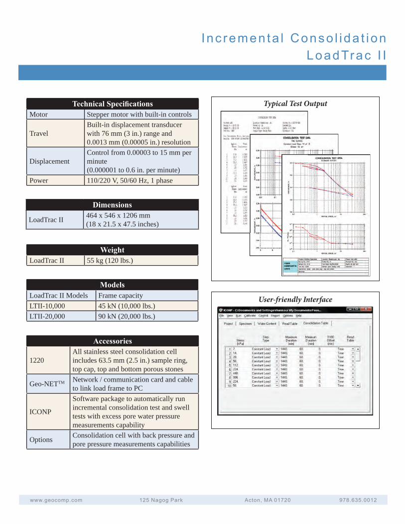
Technical Specifi cationsMotor Stepper motor with built-in controls
TravelBuilt-in displacement transducer with 76 mm (3 in.) range and 0.0013 mm (0.00005 in.) resolution
DisplacementControl from 0.00003 to 15 mm per minute (0.000001 to 0.6 in. per minute)
Power 110/220 V, 50/60 Hz, 1 phase
Typical Test Output
User-friendly Interface
Dimensions
LoadTrac II 464 x 546 x 1206 mm(18 x 21.5 x 47.5 inches)
WeightLoadTrac II 55 kg (120 lbs.)
ModelsLoadTrac II Models Frame capacityLTII-10,000 45 kN (10,000 lbs.)LTII-20,000 90 kN (20,000 lbs.)
Accessories
1220All stainless steel consolidation cell includes 63.5 mm (2.5 in.) sample ring, top cap, top and bottom porous stones
Geo-NETTM Network / communication card and cable to link load frame to PC
ICONP
Software package to automatically run incremental consolidation test and swell tests with excess pore water pressure measurements capability
Options Consolidation cell with back pressure and pore pressure measurements capabilities
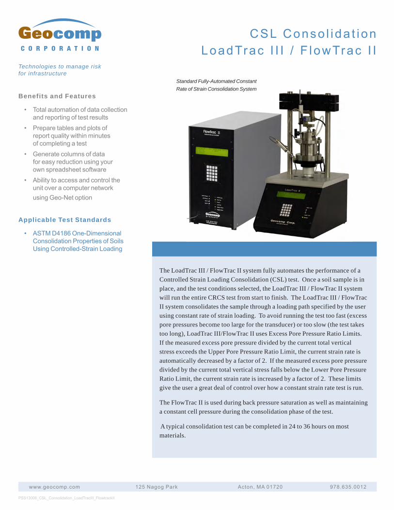
Benefits and Features
• Totalautomationofdatacollectionandreportingoftestresults
• Preparetablesandplotsofreportqualitywithinminutesofcompletingatest
• Generatecolumnsofdataforeasyreductionusingyourownspreadsheetsoftware
• AbilitytoaccessandcontroltheunitoveracomputernetworkusingGeo-Netoption
Applicable Test Standards
• ASTMD4186One-DimensionalConsolidationPropertiesofSoilsUsingControlled-StrainLoading
The LoadTrac III / FlowTrac II system fully automates the performance of a Controlled Strain Loading Consolidation (CSL) test. Once a soil sample is in place, and the test conditions selected, the LoadTrac III / FlowTrac II system will run the entire CRCS test from start to finish. The LoadTrac III / FlowTrac II system consolidates the sample through a loading path specified by the user using constant rate of strain loading. To avoid running the test too fast (excess pore pressures become too large for the transducer) or too slow (the test takes too long), LoadTrac III/FlowTrac II uses Excess Pore Pressure Ratio Limits. If the measured excess pore pressure divided by the current total vertical stress exceeds the Upper Pore Pressure Ratio Limit, the current strain rate is automatically decreased by a factor of 2. If the measured excess pore pressure divided by the current total vertical stress falls below the Lower Pore Pressure Ratio Limit, the current strain rate is increased by a factor of 2. These limits give the user a great deal of control over how a constant strain rate test is run.
The FlowTrac II is used during back pressure saturation as well as maintaining a constant cell pressure during the consolidation phase of the test.
A typical consolidation test can be completed in 24 to 36 hours on most materials.
PSS13006_CSL_Consolidation_LoadTracIII_FlowtrackII
www.geocomp.com 125NagogPark Acton,MA01720 978.635.0012
C O R P O R A T I O N
Technologies to manage risk for infrastructure
CSLConso l i da t i onLoadTrac I I I / F lowTrac I I
Standard Fully-Automated Constant Rate of Strain Consolidation System
CSLConso l i da t i onLoadTrac I I I / F lowTrac I I
www.geocomp.com 125NagogPark Acton,MA01720 978.635.0012
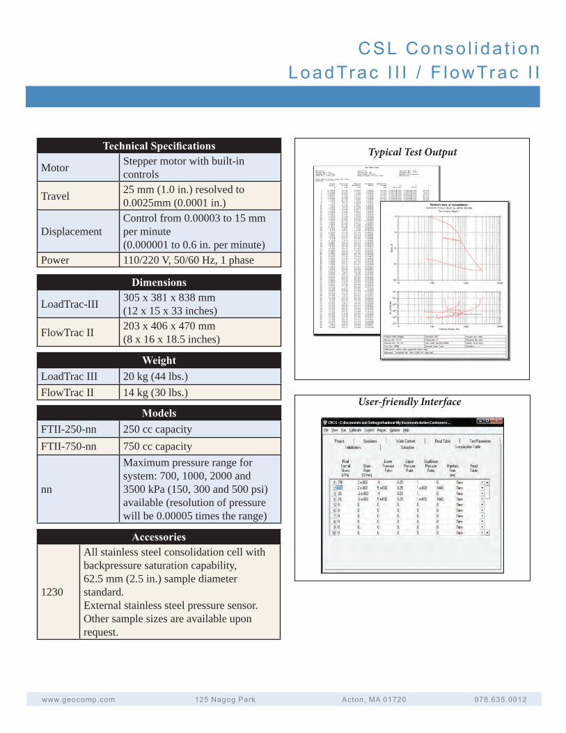
Technical Specifi cations
Motor Stepper motor with built-in controls
Travel 25 mm (1.0 in.) resolved to 0.0025mm (0.0001 in.)
DisplacementControl from 0.00003 to 15 mm per minute (0.000001 to 0.6 in. per minute)
Power 110/220 V, 50/60 Hz, 1 phase
Dimensions
LoadTrac-III 305 x 381 x 838 mm(12 x 15 x 33 inches)
FlowTrac II 203 x 406 x 470 mm(8 x 16 x 18.5 inches)
WeightLoadTrac III 20 kg (44 lbs.)FlowTrac II 14 kg (30 lbs.)
Accessories
1230
All stainless steel consolidation cell with backpressure saturation capability, 62.5 mm (2.5 in.) sample diameter standard.External stainless steel pressure sensor.Other sample sizes are available upon request.
Typical Test Output
ModelsFTII-250-nn 250 cc capacityFTII-750-nn 750 cc capacity
nn
Maximum pressure range for system: 700, 1000, 2000 and 3500 kPa (150, 300 and 500 psi) available (resolution of pressure will be 0.00005 times the range)
User-friendly Interface
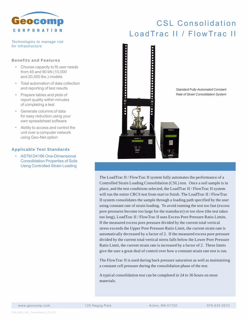
Benefits and Features• Choosecapacitytofituserneeds
from45and90kN(10,000and20,000lbs.)models
• Totalautomationofdatacollectionandreportingoftestresults
• Preparetablesandplotsofreportqualitywithinminutesofcompletingatest
• Generatecolumnsofdataforeasyreductionusingyourownspreadsheetsoftware
• AbilitytoaccessandcontroltheunitoveracomputernetworkusingGeo-Netoption
Applicable Test Standards• ASTMD4186One-Dimensional
ConsolidationPropertiesofSoilsUsingControlled-StrainLoading
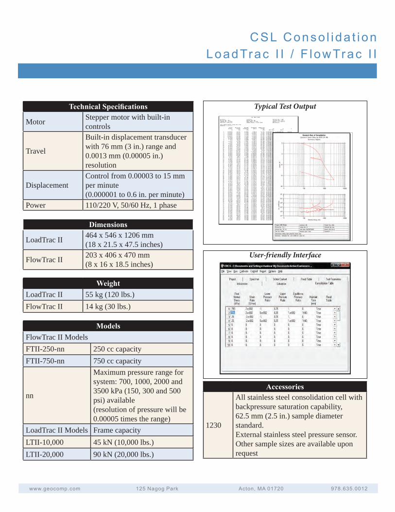
The LoadTrac II / FlowTrac II system fully automates the performance of a Controlled Strain Loading Consolidation (CSL) test. Once a soil sample is in place, and the test conditions selected, the LoadTrac II / FlowTrac II system will run the entire CRCS test from start to finish. The LoadTrac II / FlowTrac II system consolidates the sample through a loading path specified by the user using constant rate of strain loading. To avoid running the test too fast (excess pore pressures become too large for the transducer) or too slow (the test takes too long), LoadTrac II / FlowTrac II uses Excess Pore Pressure Ratio Limits. If the measured excess pore pressure divided by the current total vertical stress exceeds the Upper Pore Pressure Ratio Limit, the current strain rate is automatically decreased by a factor of 2. If the measured excess pore pressure divided by the current total vertical stress falls below the Lower Pore Pressure Ratio Limit, the current strain rate is increased by a factor of 2. These limits give the user a great deal of control over how a constant strain rate test is run.
The FlowTrac II is used during back pressure saturation as well as maintaining a constant cell pressure during the consolidation phase of the test.
A typical consolidation test can be completed in 24 to 36 hours on most materials.
PSS13005_CSL_Consolidation_LTII_FTII
www.geocomp.com 125NagogPark Acton,MA01720 978.635.0012
C O R P O R A T I O N
Technologies to manage risk for infrastructure
Standard Fully-Automated Constant Rate of Strain Consolidation System
CSLConso l i da t i onLoadTrac I I / F lowTrac I I
CSLConso l i da t i onLoadTrac I I / F lowTrac I I
www.geocomp.com 125NagogPark Acton,MA01720 978.635.0012
Technical Specifi cations
Motor Stepper motor with built-in controls
Travel
Built-in displacement transducer with 76 mm (3 in.) range and 0.0013 mm (0.00005 in.) resolution
DisplacementControl from 0.00003 to 15 mm per minute (0.000001 to 0.6 in. per minute)
Power 110/220 V, 50/60 Hz, 1 phase
Dimensions
LoadTrac II 464 x 546 x 1206 mm(18 x 21.5 x 47.5 inches)
FlowTrac II 203 x 406 x 470 mm(8 x 16 x 18.5 inches)
WeightLoadTrac II 55 kg (120 lbs.)FlowTrac II 14 kg (30 lbs.)
Accessories
1230
All stainless steel consolidation cell with backpressure saturation capability, 62.5 mm (2.5 in.) sample diameter standard. External stainless steel pressure sensor.Other sample sizes are available upon request
Typical Test Output
User-friendly Interface
ModelsFlowTrac II ModelsFTII-250-nn 250 cc capacityFTII-750-nn 750 cc capacity
nn
Maximum pressure range for system: 700, 1000, 2000 and 3500 kPa (150, 300 and 500 psi) available (resolution of pressure will be 0.00005 times the range)
LoadTrac II Models Frame capacityLTII-10,000 45 kN (10,000 lbs.)LTII-20,000 90 kN (20,000 lbs.)
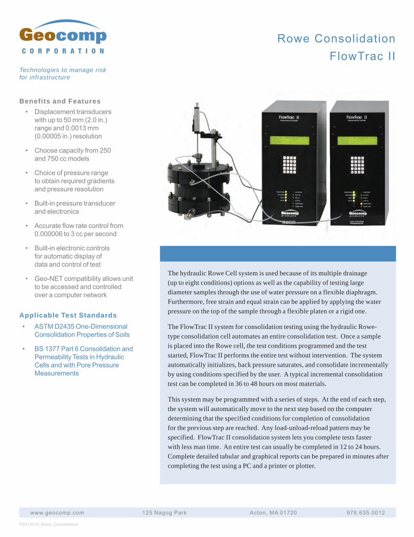
Benefits and Features• Displacement transducers
with up to 50 mm (2.0 in.)range and 0.0013 mm(0.00005 in.) resolution
• Choose capacity from 250and 750 cc models
• Choice of pressure rangeto obtain required gradientsand pressure resolution
• Built-in pressure transducerand electronics
• Accurate flow rate control from0.000006 to 3 cc per second
• Built-in electronic controlsfor automatic display ofdata and control of test
• Geo-NET compatibility allows unitto be accessed and controlledover a computer network
Applicable Test Standards• ASTM D2435 One-Dimensional
Consolidation Properties of Soils
• BS 1377 Part 6 Consolidation andPermeability Tests in HydraulicCells and with Pore PressureMeasurements
The hydraulic Rowe Cell system is used because of its multiple drainage (up to eight conditions) options as well as the capability of testing large diameter samples through the use of water pressure on a flexible diaphragm. Furthermore, free strain and equal strain can be applied by applying the water pressure on the top of the sample through a flexible platen or a rigid one.
The FlowTrac II system for consolidation testing using the hydraulic Rowe-type consolidation cell automates an entire consolidation test. Once a sample is placed into the Rowe cell, the test conditions programmed and the test started, FlowTrac II performs the entire test without intervention. The system automatically initializes, back pressure saturates, and consolidate incrementally by using conditions specified by the user. A typical incremental consolidation test can be completed in 36 to 48 hours on most materials.
This system may be programmed with a series of steps. At the end of each step, the system will automatically move to the next step based on the computer determining that the specified conditions for completion of consolidation for the previous step are reached. Any load-unload-reload pattern may be specified. FlowTrac II consolidation system lets you complete tests faster with less man time. An entire test can usually be completed in 12 to 24 hours. Complete detailed tabular and graphical reports can be prepared in minutes after completing the test using a PC and a printer or plotter.
PSS13019_Rowe_Consolidation
www.geocomp.com 125 Nagog Park Acton, MA 01720 978.635.0012
C O R P O R A T I O N
Technologies to manage risk for infrastructure
Rowe ConsolidationFlowTrac II
Rowe ConsolidationFlowTrac II
www.geocomp.com 125 Nagog Park Acton, MA 01720 978.635.0012
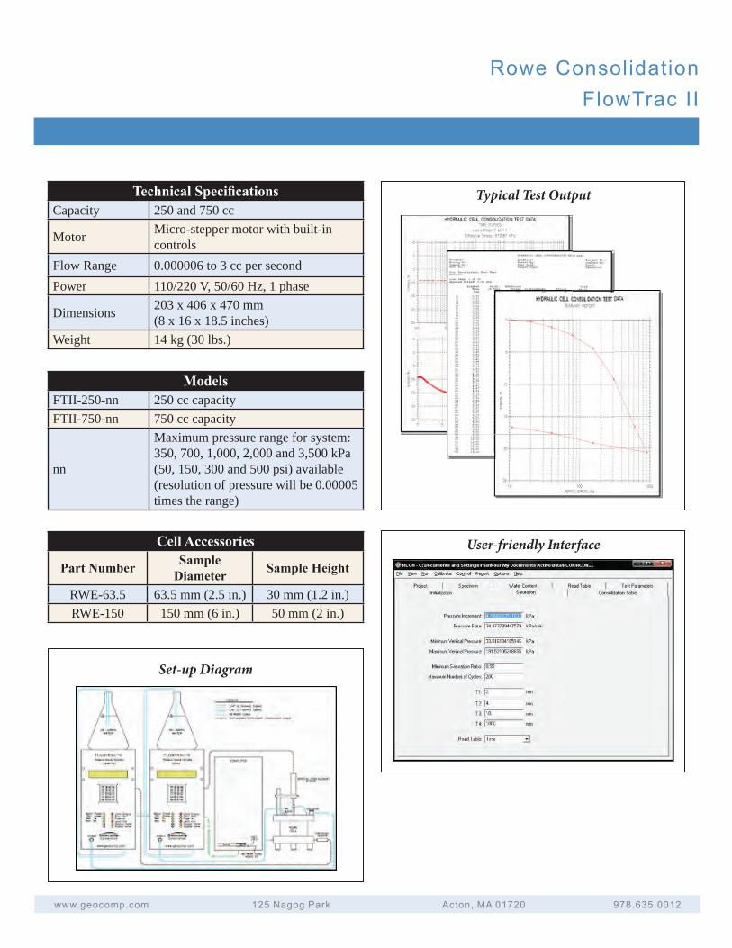
Technical Specifi cationsCapacity 250 and 750 cc
Motor Micro-stepper motor with built-in controls
Flow Range 0.000006 to 3 cc per secondPower 110/220 V, 50/60 Hz, 1 phase
Dimensions 203 x 406 x 470 mm(8 x 16 x 18.5 inches)
Weight 14 kg (30 lbs.)
Typical Test Output
User-friendly Interface
ModelsFTII-250-nn 250 cc capacityFTII-750-nn 750 cc capacity
nn
Maximum pressure range for system: 350, 700, 1,000, 2,000 and 3,500 kPa (50, 150, 300 and 500 psi) available (resolution of pressure will be 0.00005 times the range)
Cell Accessories
Part Number Sample Diameter Sample Height
RWE-63.5 63.5 mm (2.5 in.) 30 mm (1.2 in.)RWE-150 150 mm (6 in.) 50 mm (2 in.)
Set-up Diagram
A u t o m a t e d D i r e c t S h e a r a n d D i r e c t S i m p l e S h e a r S y s t e m s
Direct Shear
Residual Shear
Rock Interface Shear
Large Direct Shear
Large Interface Shear
Direct Simple Shear
Cyclic Simple Shear
Large Cyclic Simple Shear
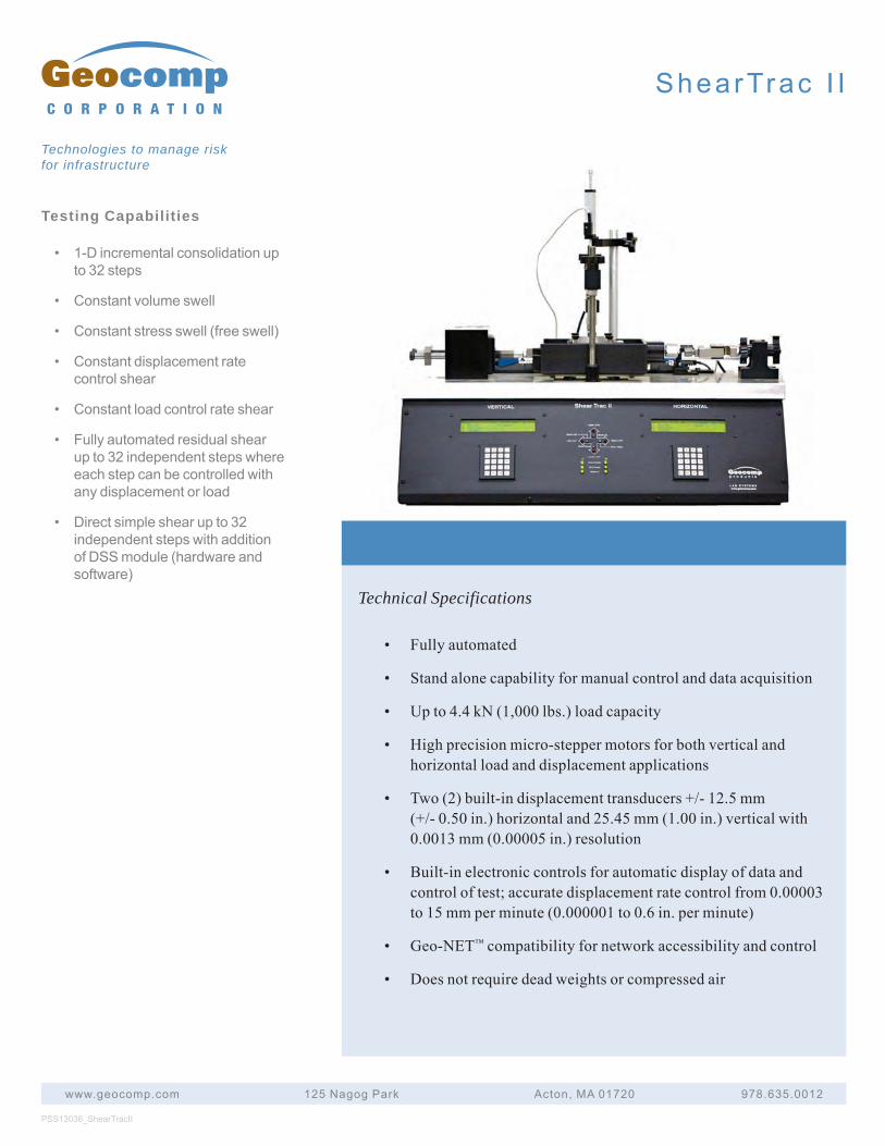
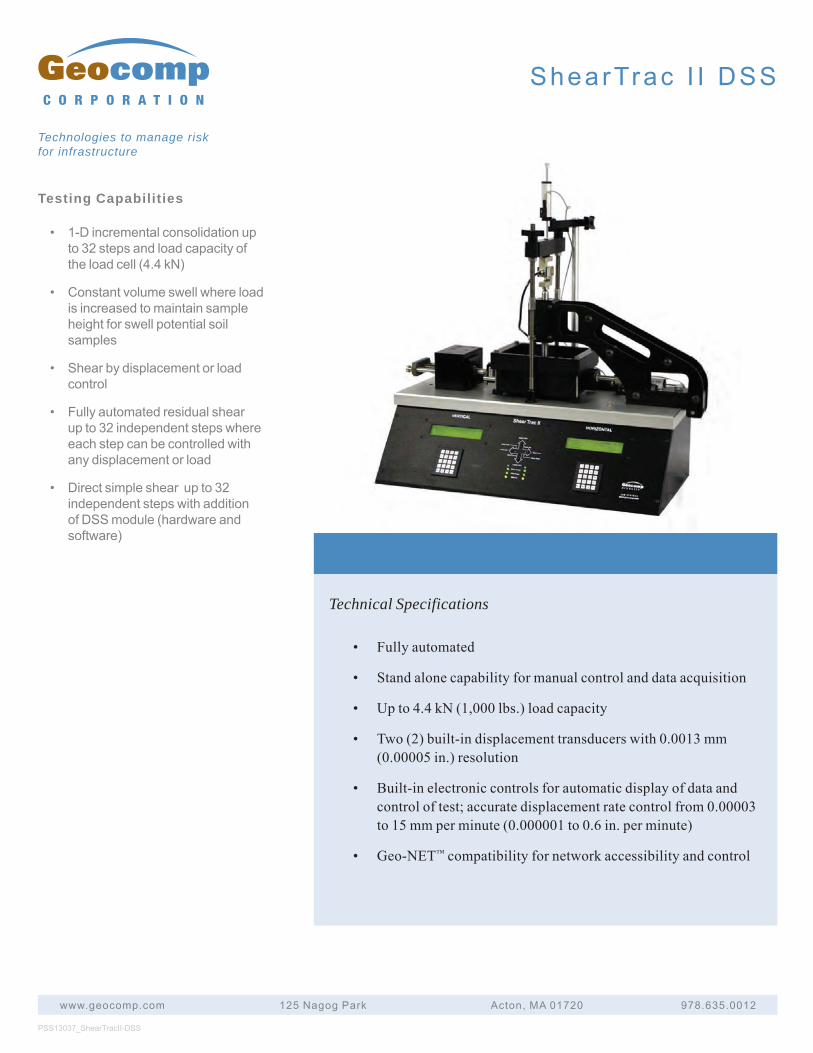
Testing Capabilities
• 1-D incremental consolidation upto 32 steps
• Constant volume swell
• Constant stress swell (free swell)
• Constant displacement ratecontrol shear
• Constant load control rate shear
• Fully automated residual shearup to 32 independent steps whereeach step can be controlled withany displacement or load
• Direct simple shear up to 32independent steps with additionof DSS module (hardware andsoftware)
PSS13036_ShearTracII
www.geocomp.com 125 Nagog Park Acton, MA 01720 978.635.0012
C O R P O R A T I O N
Technologies to manage risk for infrastructure
ShearTrac I I
Technical Specifications
• Fully automated
• Stand alone capability for manual control and data acquisition
• Up to 4.4 kN (1,000 lbs.) load capacity
• High precision micro-stepper motors for both vertical andhorizontal load and displacement applications
• Two (2) built-in displacement transducers +/- 12.5 mm(+/- 0.50 in.) horizontal and 25.45 mm (1.00 in.) vertical with0.0013 mm (0.00005 in.) resolution
• Built-in electronic controls for automatic display of data andcontrol of test; accurate displacement rate control from 0.00003to 15 mm per minute (0.000001 to 0.6 in. per minute)
• Geo-NET™ compatibility for network accessibility and control
• Does not require dead weights or compressed air
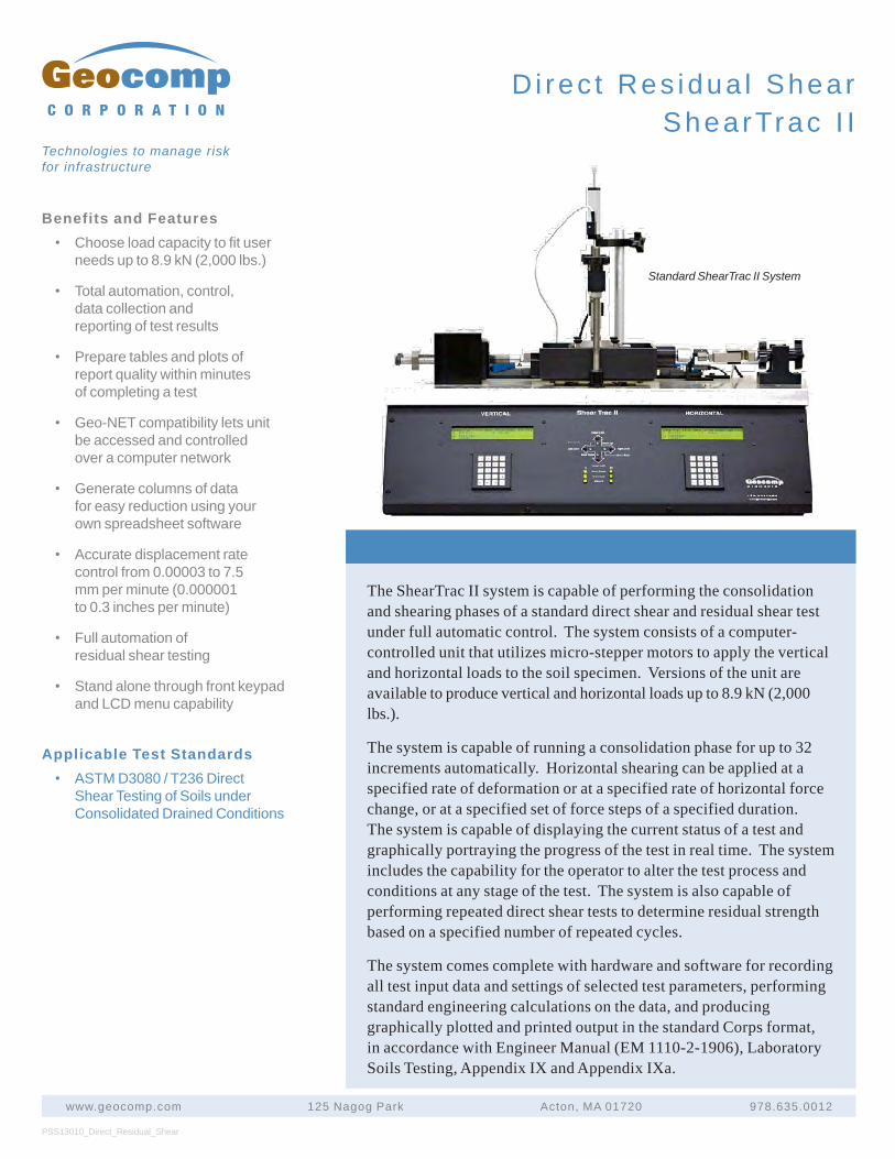
The ShearTrac II system is capable of performing the consolidation and shearing phases of a standard direct shear and residual shear test under full automatic control. The system consists of a computer-controlled unit that utilizes micro-stepper motors to apply the vertical and horizontal loads to the soil specimen. Versions of the unit are available to produce vertical and horizontal loads up to 8.9 kN (2,000 lbs.).
The system is capable of running a consolidation phase for up to 32 increments automatically. Horizontal shearing can be applied at a specified rate of deformation or at a specified rate of horizontal force change, or at a specified set of force steps of a specified duration. The system is capable of displaying the current status of a test and graphically portraying the progress of the test in real time. The system includes the capability for the operator to alter the test process and conditions at any stage of the test. The system is also capable of performing repeated direct shear tests to determine residual strength based on a specified number of repeated cycles.
The system comes complete with hardware and software for recording all test input data and settings of selected test parameters, performing standard engineering calculations on the data, and producing graphically plotted and printed output in the standard Corps format, in accordance with Engineer Manual (EM 1110-2-1906), Laboratory Soils Testing, Appendix IX and Appendix IXa.
PSS13010_Direct_Residual_Shear
www.geocomp.com 125 Nagog Park Acton, MA 01720 978.635.0012
C O R P O R A T I O N
Technologies to manage risk for infrastructure
Di rec t Res idua l ShearShearTrac I I
Standard ShearTrac II System
Benefits and Features• Choose load capacity to fit user
needs up to 8.9 kN (2,000 lbs.)
• Total automation, control,data collection andreporting of test results
• Prepare tables and plots ofreport quality within minutesof completing a test
• Geo-NET compatibility lets unitbe accessed and controlledover a computer network
• Generate columns of datafor easy reduction using yourown spreadsheet software
• Accurate displacement ratecontrol from 0.00003 to 7.5mm per minute (0.000001to 0.3 inches per minute)
• Full automation ofresidual shear testing
• Stand alone through front keypadand LCD menu capability
Applicable Test Standards• ASTM D3080 / T236 Direct
Shear Testing of Soils underConsolidated Drained Conditions
Di rec t Res idua l ShearShearTrac I I
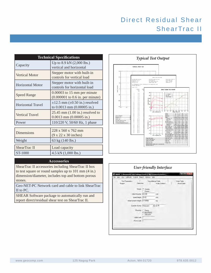
Technical Specifications
Capacity Up to 8.9 kN (2,000 lbs.)vertical and horizontal
Vertical Motor Stepper motor with built-in controls for vertical load
Horizontal Motor Stepper motor with built-in controls for horizontal load
Speed Range 0.00003 to 15 mm per minute (0.000001 to 0.6 in. per minute)
Horizontal Travel ±12.5 mm (±0.50 in.) resolved to 0.0013 mm (0.00005 in.)
Vertical Travel 25.45 mm (1.00 in.) resolved to 0.0013 mm (0.00005 in.)
Power 110/220 V, 50/60 Hz, 1 phase
User-friendly Interface
www.geocomp.com 125 Nagog Park Acton, MA 01720 978.635.0012
AccessoriesShearTrac II accessories including ShearTrac II box to test square or round samples up to 101 mm (4 in.) dimension/diameter, includes top and bottom porous stones.Geo-NET-PC Network card and cable to link ShearTrac II to PC.SHEAR Software package to automatically run and report direct/residual shear test on ShearTrac II.
Typical Test Output
Dimensions 228 x 560 x 762 mm (9 x 22 x 30 inches)
Weight 63 kg (140 lbs.)
ShearTrac II Load capacityST-1000 4.5 kN (1,000 lbs.)
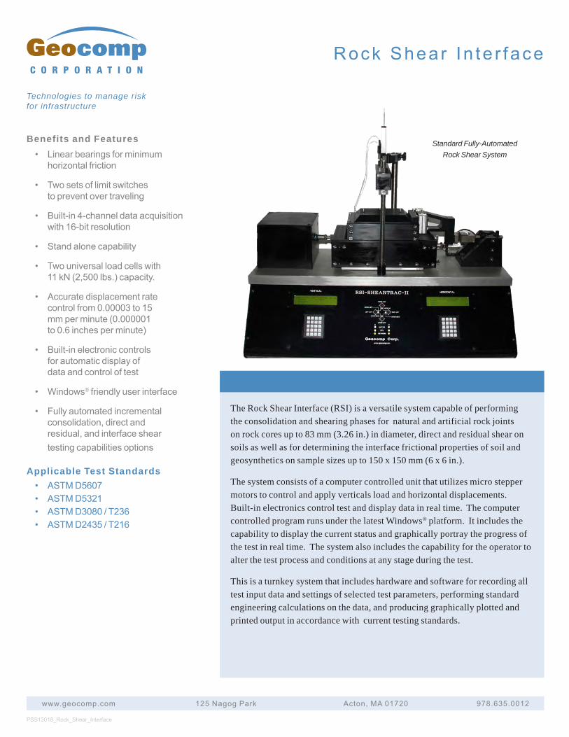
Benefits and Features• Linearbearingsforminimum
horizontalfriction
• Twosetsoflimitswitchestopreventovertraveling
• Built-in4-channeldataacquisitionwith16-bitresolution
• Standalonecapability
• Twouniversalloadcellswith11kN(2,500lbs.)capacity.
• Accuratedisplacementratecontrolfrom0.00003to15mmperminute(0.000001to0.6inchesperminute)
• Built-inelectroniccontrolsforautomaticdisplayofdataandcontroloftest
• Windows®friendlyuserinterface
• Fullyautomatedincrementalconsolidation,directandresidual,andinterfacesheartestingcapabilitiesoptions
Applicable Test Standards• ASTMD5607• ASTMD5321• ASTMD3080/T236• ASTMD2435/T216
The Rock Shear Interface (RSI) is a versatile system capable of performing the consolidation and shearing phases for natural and artificial rock joints on rock cores up to 83 mm (3.26 in.) in diameter, direct and residual shear on soils as well as for determining the interface frictional properties of soil and geosynthetics on sample sizes up to 150 x 150 mm (6 x 6 in.).
The system consists of a computer controlled unit that utilizes micro stepper motors to control and apply verticals load and horizontal displacements. Built-in electronics control test and display data in real time. The computer controlled program runs under the latest Windows® platform. It includes the capability to display the current status and graphically portray the progress of the test in real time. The system also includes the capability for the operator to alter the test process and conditions at any stage during the test.
This is a turnkey system that includes hardware and software for recording all test input data and settings of selected test parameters, performing standard engineering calculations on the data, and producing graphically plotted and printed output in accordance with current testing standards.
PSS13018_Rock_Shear_Interface
www.geocomp.com 125NagogPark Acton,MA01720 978.635.0012
C O R P O R A T I O N
Technologies to manage risk for infrastructure
Standard Fully-Automated Rock Shear System
Rock Shear In te r face
Rock Shear In te r face
www.geocomp.com 125NagogPark Acton,MA01720 978.635.0012
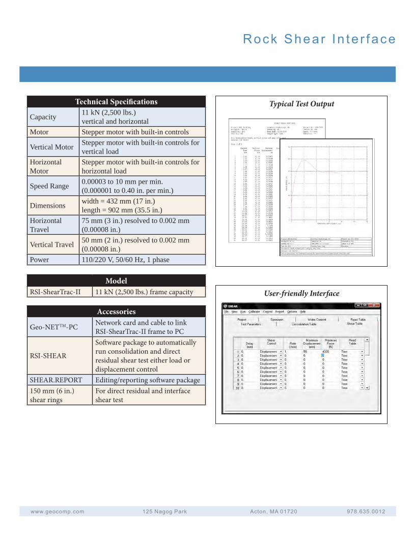
Technical Specifications
Capacity 11 kN (2,500 lbs.)vertical and horizontal
Motor Stepper motor with built-in controls
Vertical Motor Stepper motor with built-in controls for vertical load
Horizontal Motor
Stepper motor with built-in controls for horizontal load
Speed Range 0.00003 to 10 mm per min. (0.000001 to 0.40 in. per min.)
Dimensions width = 432 mm (17 in.) length = 902 mm (35.5 in.)
Horizontal Travel
75 mm (3 in.) resolved to 0.002 mm (0.00008 in.)
Vertical Travel 50 mm (2 in.) resolved to 0.002 mm (0.00008 in.)
Power 110/220 V, 50/60 Hz, 1 phase
Typical Test Output
User-friendly InterfaceModel
RSI-ShearTrac-II 11 kN (2,500 lbs.) frame capacity
Accessories
Geo-NETTM-PC Network card and cable to link RSI-ShearTrac-II frame to PC
RSI-SHEAR
Software package to automatically run consolidation and direct residual shear test either load or displacement control
SHEAR.REPORT Editing/reporting software package150 mm (6 in.) shear rings
For direct residual and interface shear test
Testing Capabilities
• Interfacefrictionalpropertiesofsoil&geosynthetics
• InternalfrictionofGC
• Directshearonsoilandaggregates
• 1-Dincrementalconsolidationupto32steps
• Constantvolumeswell
• Constantstressswell(freeswell)
• Constantdisplacementratecontrolshear
• Constantloadcontrolrateshear
• Directshearupto32independentsteps
• CapabilitytoupgradetoDSStesting
PSS13038_Large_ShearTracIII
www.geocomp.com 125NagogPark Acton,MA01720 978.635.0012
C O R P O R A T I O N
Technologies to manage risk for infrastructure
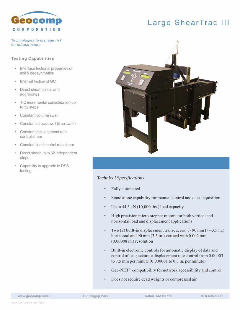
Large ShearTrac I I I
Technical Specifications
• Fullyautomated
• Standalonecapabilityformanualcontrolanddataacquisition
• Upto44.5kN(10,000lbs.)loadcapacity
• Highprecisionmicro-steppermotorsforbothverticalandhorizontalloadanddisplacementapplications
• Two(2)built-indisplacementtransducers+/-90mm(+/-3.5in.)horizontaland90mm(3.5in.)verticalwith0.002mm(0.00008in.)resolution
• Built-inelectroniccontrolsforautomaticdisplayofdataandcontroloftest;accuratedisplacementratecontrolfrom0.00003to7.5mmperminute(0.000001to0.3in.perminute)
• Geo-NET™compatibilityfornetworkaccessibilityandcontrol
• Doesnotrequiredeadweightsorcompressedair
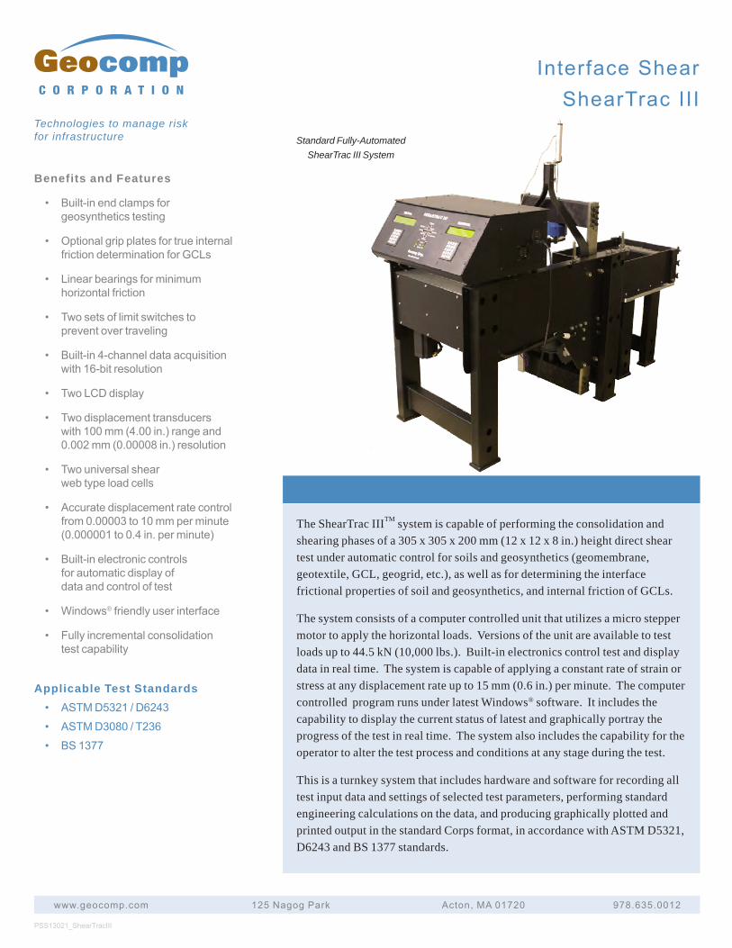
Benefits and Features
• Built-inendclampsforgeosyntheticstesting
• OptionalgripplatesfortrueinternalfrictiondeterminationforGCLs
• Linearbearingsforminimumhorizontalfriction
• Twosetsoflimitswitchestopreventovertraveling
• Built-in4-channeldataacquisitionwith16-bitresolution
• TwoLCDdisplay
• Twodisplacementtransducerswith100mm(4.00in.)rangeand0.002mm(0.00008in.)resolution
• Twouniversalshearwebtypeloadcells
• Accuratedisplacementratecontrolfrom0.00003to10mmperminute(0.000001to0.4in.perminute)
• Built-inelectroniccontrolsforautomaticdisplayofdataandcontroloftest
• Windows®friendlyuserinterface
• Fullyincrementalconsolidationtestcapability
Applicable Test Standards• ASTMD5321/D6243
• ASTMD3080/T236
• BS1377
The ShearTrac IIITM system is capable of performing the consolidation and shearing phases of a 305 x 305 x 200 mm (12 x 12 x 8 in.) height direct shear test under automatic control for soils and geosynthetics (geomembrane, geotextile, GCL, geogrid, etc.), as well as for determining the interface frictional properties of soil and geosynthetics, and internal friction of GCLs.
The system consists of a computer controlled unit that utilizes a micro stepper motor to apply the horizontal loads. Versions of the unit are available to test loads up to 44.5 kN (10,000 lbs.). Built-in electronics control test and display data in real time. The system is capable of applying a constant rate of strain or stress at any displacement rate up to 15 mm (0.6 in.) per minute. The computer controlled program runs under latest Windows® software. It includes the capability to display the current status of latest and graphically portray the progress of the test in real time. The system also includes the capability for the operator to alter the test process and conditions at any stage during the test.
This is a turnkey system that includes hardware and software for recording all test input data and settings of selected test parameters, performing standard engineering calculations on the data, and producing graphically plotted and printed output in the standard Corps format, in accordance with ASTM D5321, D6243 and BS 1377 standards.
PSS13021_ShearTracIII
www.geocomp.com 125NagogPark Acton,MA01720 978.635.0012
C O R P O R A T I O N
Technologies to manage risk for infrastructure Standard Fully-Automated
ShearTrac III System
InterfaceShearShearTracIII
InterfaceShearShearTracIII
www.geocomp.com 125NagogPark Acton,MA01720 978.635.0012
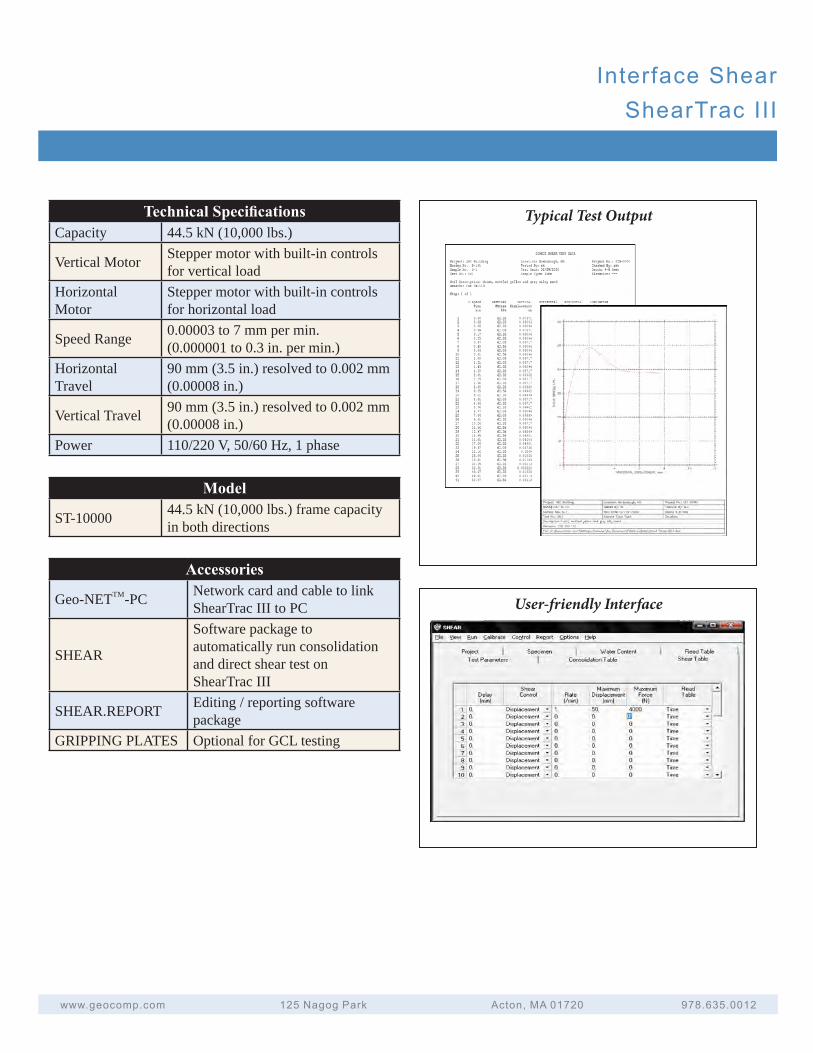
Technical SpecificationsCapacity 44.5 kN (10,000 lbs.)
Vertical Motor Stepper motor with built-in controls for vertical load
Horizontal Motor
Stepper motor with built-in controls for horizontal load
Speed Range 0.00003 to 7 mm per min. (0.000001 to 0.3 in. per min.)
Horizontal Travel
90 mm (3.5 in.) resolved to 0.002 mm (0.00008 in.)
Vertical Travel 90 mm (3.5 in.) resolved to 0.002 mm (0.00008 in.)
Power 110/220 V, 50/60 Hz, 1 phase
Typical Test Output
User-friendly Interface
Model
ST-10000 44.5 kN (10,000 lbs.) frame capacity in both directions
Accessories
Geo-NETTM-PC Network card and cable to link ShearTrac III to PC
SHEAR
Software package to automatically run consolidation and direct shear test on ShearTrac III
SHEAR.REPORT Editing / reporting software package
GRIPPING PLATES Optional for GCL testing
Testing Capabilities
• 1-D incremental consolidation upto 32 steps and load capacity ofthe load cell (4.4 kN)
• Constant volume swell where loadis increased to maintain sampleheight for swell potential soilsamples
• Shear by displacement or loadcontrol
• Fully automated residual shearup to 32 independent steps whereeach step can be controlled withany displacement or load
• Direct simple shear up to 32independent steps with additionof DSS module (hardware andsoftware)
PSS13037_ShearTracII-DSS
www.geocomp.com 125 Nagog Park Acton, MA 01720 978.635.0012
C O R P O R A T I O N
Technologies to manage risk for infrastructure
ShearTrac I I DSS
Technical Specifications
• Fully automated
• Stand alone capability for manual control and data acquisition
• Up to 4.4 kN (1,000 lbs.) load capacity
• Two (2) built-in displacement transducers with 0.0013 mm(0.00005 in.) resolution
• Built-in electronic controls for automatic display of data andcontrol of test; accurate displacement rate control from 0.00003to 15 mm per minute (0.000001 to 0.6 in. per minute)
• Geo-NET™ compatibility for network accessibility and control
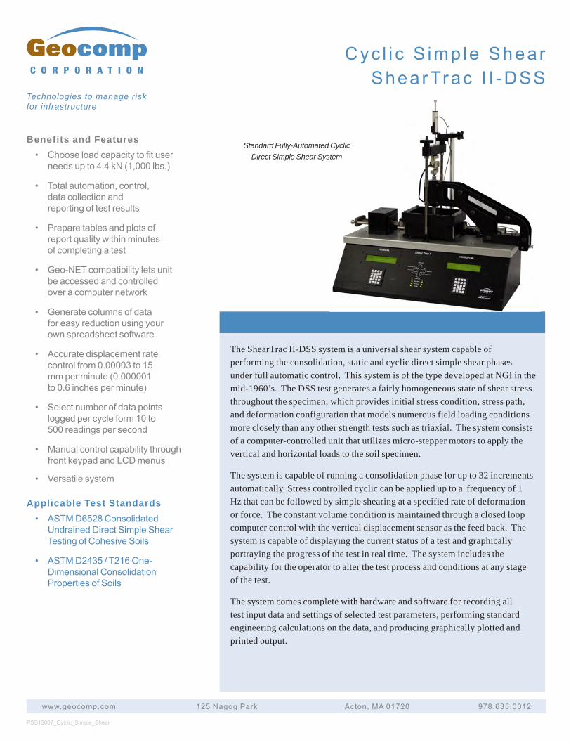
Benefits and Features• Chooseloadcapacitytofituser
needsupto4.4kN(1,000lbs.)
• Totalautomation,control,datacollectionandreportingoftestresults
• Preparetablesandplotsofreportqualitywithinminutesofcompletingatest
• Geo-NETcompatibilityletsunitbeaccessedandcontrolledoveracomputernetwork
• Generatecolumnsofdataforeasyreductionusingyourownspreadsheetsoftware
• Accuratedisplacementratecontrolfrom0.00003to15mmperminute(0.000001to0.6inchesperminute)
• Selectnumberofdatapointsloggedpercycleform10to500readingspersecond
• ManualcontrolcapabilitythroughfrontkeypadandLCDmenus
• Versatilesystem
Applicable Test Standards• ASTMD6528Consolidated
UndrainedDirectSimpleShearTestingofCohesiveSoils
• ASTMD2435/T216One-DimensionalConsolidationPropertiesofSoils
The ShearTrac II-DSS system is a universal shear system capable of performing the consolidation, static and cyclic direct simple shear phases under full automatic control. This system is of the type developed at NGI in the mid-1960’s. The DSS test generates a fairly homogeneous state of shear stress throughout the specimen, which provides initial stress condition, stress path, and deformation configuration that models numerous field loading conditions more closely than any other strength tests such as triaxial. The system consists of a computer-controlled unit that utilizes micro-stepper motors to apply the vertical and horizontal loads to the soil specimen.
The system is capable of running a consolidation phase for up to 32 increments automatically. Stress controlled cyclic can be applied up to a frequency of 1 Hz that can be followed by simple shearing at a specified rate of deformation or force. The constant volume condition is maintained through a closed loop computer control with the vertical displacement sensor as the feed back. The system is capable of displaying the current status of a test and graphically portraying the progress of the test in real time. The system includes the capability for the operator to alter the test process and conditions at any stage of the test.
The system comes complete with hardware and software for recording all test input data and settings of selected test parameters, performing standard engineering calculations on the data, and producing graphically plotted and printed output.
PSS13007_Cyclic_Simple_Shear
www.geocomp.com 125NagogPark Acton,MA01720 978.635.0012
C O R P O R A T I O N
Technologies to manage risk for infrastructure
Standard Fully-Automated Cyclic Direct Simple Shear System
Cyc l i c S imp le ShearShearTrac I I -DSS
Cyc l i c S imp le ShearShearTrac I I -DSS
www.geocomp.com 125NagogPark Acton,MA01720 978.635.0012
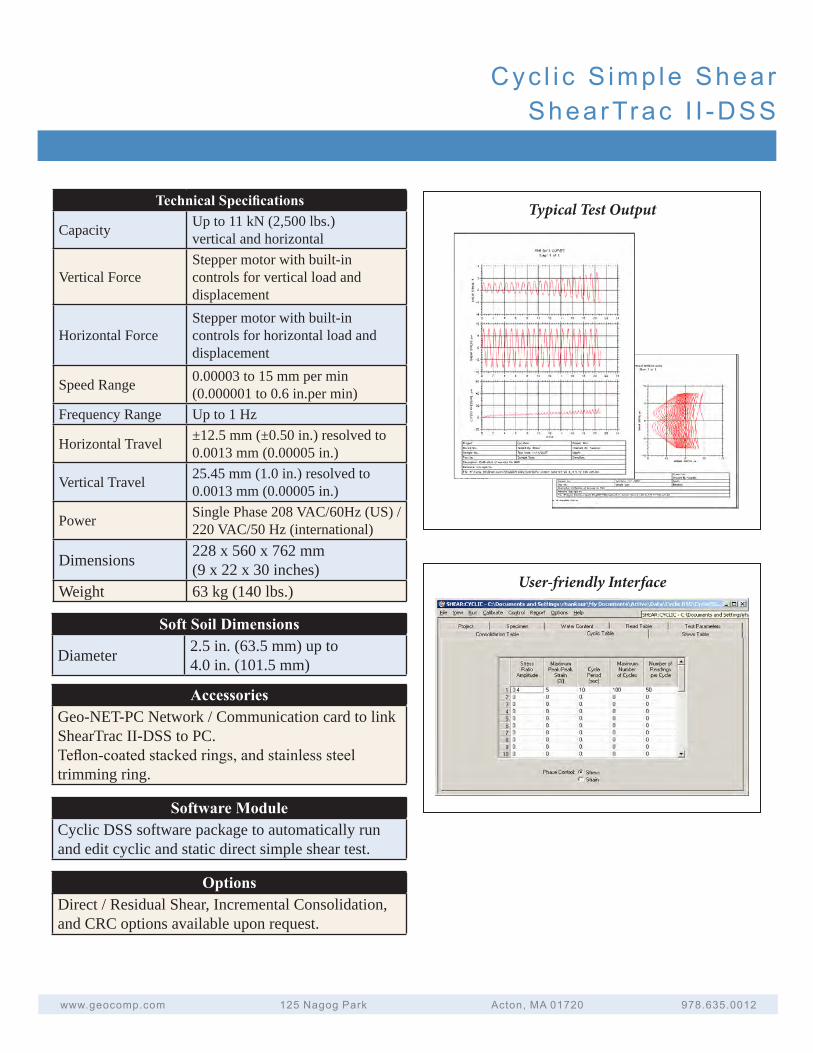
Typical Test OutputTechnical Specifications
Capacity Up to 11 kN (2,500 lbs.)vertical and horizontal
Vertical ForceStepper motor with built-in controls for vertical load and displacement
Horizontal ForceStepper motor with built-in controls for horizontal load and displacement
Speed Range 0.00003 to 15 mm per min (0.000001 to 0.6 in.per min)
Frequency Range Up to 1 Hz
Horizontal Travel ±12.5 mm (±0.50 in.) resolved to 0.0013 mm (0.00005 in.)
Vertical Travel 25.45 mm (1.0 in.) resolved to 0.0013 mm (0.00005 in.)
Power Single Phase 208 VAC/60Hz (US) / 220 VAC/50 Hz (international)
Dimensions 228 x 560 x 762 mm (9 x 22 x 30 inches)
Weight 63 kg (140 lbs.)
AccessoriesGeo-NET-PC Network / Communication card to link ShearTrac II-DSS to PC. Teflon-coated stacked rings, and stainless steel trimming ring.
User-friendly Interface
Soft Soil Dimensions
Diameter 2.5 in. (63.5 mm) up to 4.0 in. (101.5 mm)
Software ModuleCyclic DSS software package to automatically run and edit cyclic and static direct simple shear test.
OptionsDirect / Residual Shear, Incremental Consolidation, and CRC options available upon request.
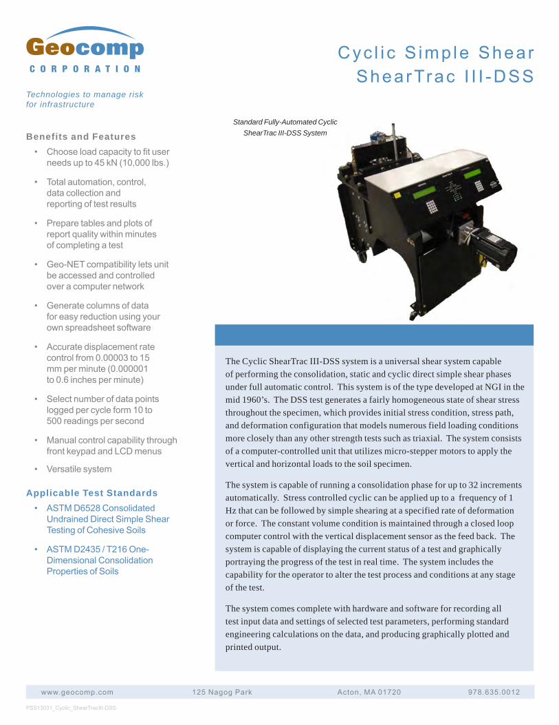
Benefits and Features• Chooseloadcapacitytofituser
needsupto45kN(10,000lbs.)
• Totalautomation,control,datacollectionandreportingoftestresults
• Preparetablesandplotsofreportqualitywithinminutesofcompletingatest
• Geo-NETcompatibilityletsunitbeaccessedandcontrolledoveracomputernetwork
• Generatecolumnsofdataforeasyreductionusingyourownspreadsheetsoftware
• Accuratedisplacementratecontrolfrom0.00003to15mmperminute(0.000001to0.6inchesperminute)
• Selectnumberofdatapointsloggedpercycleform10to500readingspersecond
• ManualcontrolcapabilitythroughfrontkeypadandLCDmenus
• Versatilesystem
Applicable Test Standards• ASTMD6528Consolidated
UndrainedDirectSimpleShearTestingofCohesiveSoils
• ASTMD2435/T216One-DimensionalConsolidationPropertiesofSoils
The Cyclic ShearTrac III-DSS system is a universal shear system capable of performing the consolidation, static and cyclic direct simple shear phases under full automatic control. This system is of the type developed at NGI in the mid 1960’s. The DSS test generates a fairly homogeneous state of shear stress throughout the specimen, which provides initial stress condition, stress path, and deformation configuration that models numerous field loading conditions more closely than any other strength tests such as triaxial. The system consists of a computer-controlled unit that utilizes micro-stepper motors to apply the vertical and horizontal loads to the soil specimen.
The system is capable of running a consolidation phase for up to 32 increments automatically. Stress controlled cyclic can be applied up to a frequency of 1 Hz that can be followed by simple shearing at a specified rate of deformation or force. The constant volume condition is maintained through a closed loop computer control with the vertical displacement sensor as the feed back. The system is capable of displaying the current status of a test and graphically portraying the progress of the test in real time. The system includes the capability for the operator to alter the test process and conditions at any stage of the test.
The system comes complete with hardware and software for recording all test input data and settings of selected test parameters, performing standard engineering calculations on the data, and producing graphically plotted and printed output.
PSS13031_Cyclic_ShearTracIII-DSS
www.geocomp.com 125NagogPark Acton,MA01720 978.635.0012
C O R P O R A T I O N
Technologies to manage risk for infrastructure
Standard Fully-Automated Cyclic ShearTrac III-DSS System
Cyc l i c S imp le ShearShearTrac I I I -DSS
Cyc l i c S imp le ShearShearTrac I I I -DSS
www.geocomp.com 125NagogPark Acton,MA01720 978.635.0012
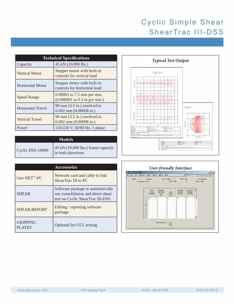
Typical Test OutputTechnical SpecificationsCapacity 45 kN (10,000 lbs.)
Vertical Motor Stepper motor with built-in controls for vertical load
Horizontal Motor Stepper motor with built-in controls for horizontal load
Speed Range 0.00003 to 7.5 mm per min. (0.000001 to 0.3 in per min.)
Horizontal Travel 90 mm (3.5 in.) resolved to 0.002 mm (0.00008 in.)
Vertical Travel 90 mm (3.5 in.) resolved to 0.002 mm (0.00008 in.)
Power 110/220 V, 50/60 Hz, 1 phase
User-friendly Interface
Models
Cyclic DSS-10000 45 kN (10,000 lbs.) frame capacity in both directions
Accessories
Geo-NET™-PC Network card and cable to link ShearTrac III to PC
SHEARSoftware package to automatically run consolidation and direct shear test on Cyclic ShearTrac III-DSS
SHEAR.REPORT Editing / reporting software package
GRIPPING PLATES Optional for GCL testing
A u t o m a t e d P e r m e a b i l i t y S y s t e m s
CV15004
Benefits and Features• Chooseloadcapacitytofituser
needsfrom45and90kN(10,000and20,000lbs.)models
• Totalautomation,control,datacollectionandreportingoftestresults
• Preparetablesandplotsofreportqualitywithinminutesofcompletingatest
• Geo-NETcompatibilityletsunitbeaccessedandcontrolledoveracomputernetwork
• Generatecolumnsofdataforeasyreductionusingyourownspreadsheetsoftware
• Choosevolumecapacitytofituserneedsfrom250and750ccmodels
• Accuratedisplacementratecontrolfrom0.00003to15mmperminute(0.000001to0.6inchesperminute)
• Accuratepressureandvolumemeasurementswithintegratedsensors
• StandalonethroughfrontkeypadandLCDmenu
Applicable Test Standards• ASTMD5084FlexibleWall
Permeability
• ASTMD2434RigidWallPermeability
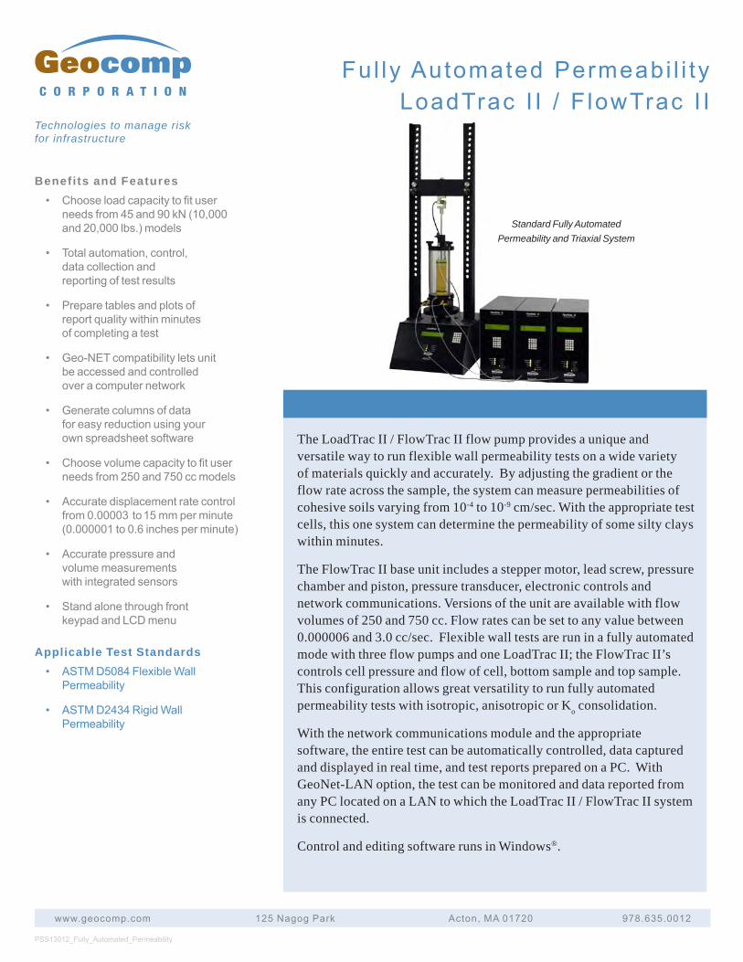
The LoadTrac II / FlowTrac II flow pump provides a unique and versatile way to run flexible wall permeability tests on a wide variety of materials quickly and accurately. By adjusting the gradient or the flow rate across the sample, the system can measure permeabilities of cohesive soils varying from 10-4 to 10-9 cm/sec. With the appropriate test cells, this one system can determine the permeability of some silty clays within minutes.
The FlowTrac II base unit includes a stepper motor, lead screw, pressure chamber and piston, pressure transducer, electronic controls and network communications. Versions of the unit are available with flow volumes of 250 and 750 cc. Flow rates can be set to any value between 0.000006 and 3.0 cc/sec. Flexible wall tests are run in a fully automated mode with three flow pumps and one LoadTrac II; the FlowTrac II’s controls cell pressure and flow of cell, bottom sample and top sample. This configuration allows great versatility to run fully automated permeability tests with isotropic, anisotropic or Ko consolidation.
With the network communications module and the appropriate software, the entire test can be automatically controlled, data captured and displayed in real time, and test reports prepared on a PC. With GeoNet-LAN option, the test can be monitored and data reported from any PC located on a LAN to which the LoadTrac II / FlowTrac II system is connected.
Control and editing software runs in Windows®.
PSS13012_Fully_Automated_Permeability
www.geocomp.com 125NagogPark Acton,MA01720 978.635.0012
C O R P O R A T I O N
Technologies to manage risk for infrastructure
Standard Fully Automated Permeability and Triaxial System
Ful ly AutomatedPermeabi l i tyLoadTrac I I / F lowTrac I I
Fu l l y Au tomated Permeab i l i t yLoadTrac I I / F lowTrac I I
www.geocomp.com 125NagogPark Acton,MA01720 978.635.0012
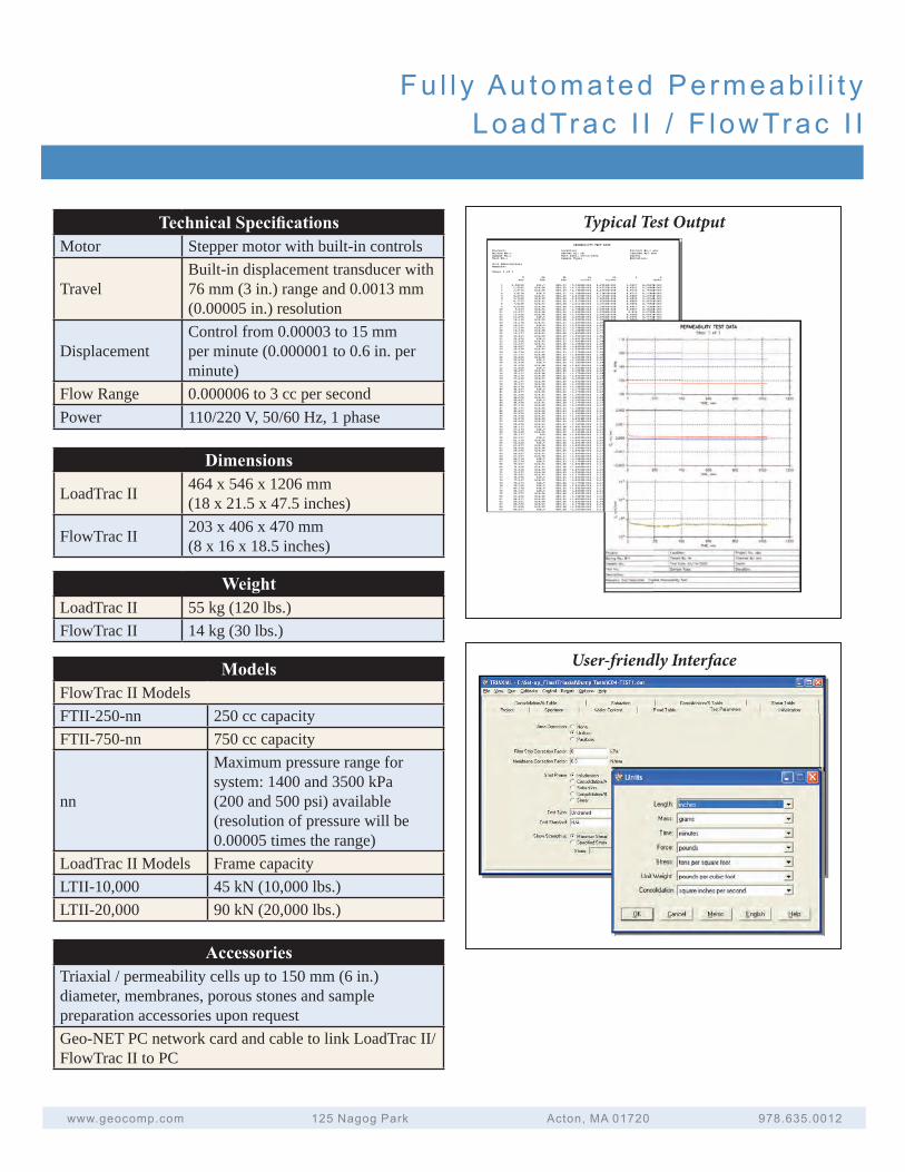
Technical Specifi cationsMotor Stepper motor with built-in controls
TravelBuilt-in displacement transducer with 76 mm (3 in.) range and 0.0013 mm (0.00005 in.) resolution
DisplacementControl from 0.00003 to 15 mm per minute (0.000001 to 0.6 in. per minute)
Flow Range 0.000006 to 3 cc per secondPower 110/220 V, 50/60 Hz, 1 phase
Typical Test Output
User-friendly Interface
Dimensions
LoadTrac II 464 x 546 x 1206 mm(18 x 21.5 x 47.5 inches)
FlowTrac II 203 x 406 x 470 mm(8 x 16 x 18.5 inches)
WeightLoadTrac II 55 kg (120 lbs.)FlowTrac II 14 kg (30 lbs.)
ModelsFlowTrac II ModelsFTII-250-nn 250 cc capacityFTII-750-nn 750 cc capacity
nn
Maximum pressure range for system: 1400 and 3500 kPa (200 and 500 psi) available (resolution of pressure will be 0.00005 times the range)
LoadTrac II Models Frame capacityLTII-10,000 45 kN (10,000 lbs.)LTII-20,000 90 kN (20,000 lbs.)
AccessoriesTriaxial / permeability cells up to 150 mm (6 in.) diameter, membranes, porous stones and sample preparation accessories upon requestGeo-NET PC network card and cable to link LoadTrac II/ FlowTrac II to PC
Benefits and Features
• Totalautomation,control,datacollectionandreportingoftestresults
• Preparetablesandplotsofreportqualitywithinminutesofcompletingatest
• Geo-NETcompatibilityletsunitbeaccessedandcontrolledoveracomputernetwork
• Generatecolumnsofdataforeasyreductionusingyourownspreadsheetsoftware
• Choosevolumecapacitytofituserneedsfrom250and750ccmodels
• Accuratepressureandvolumemeasurementswithintegratedsensors
• StandalonethroughfrontkeypadandLCDmenucapability
Applicable Test Standards
• ASTMD5084FlexibleWallPermeability
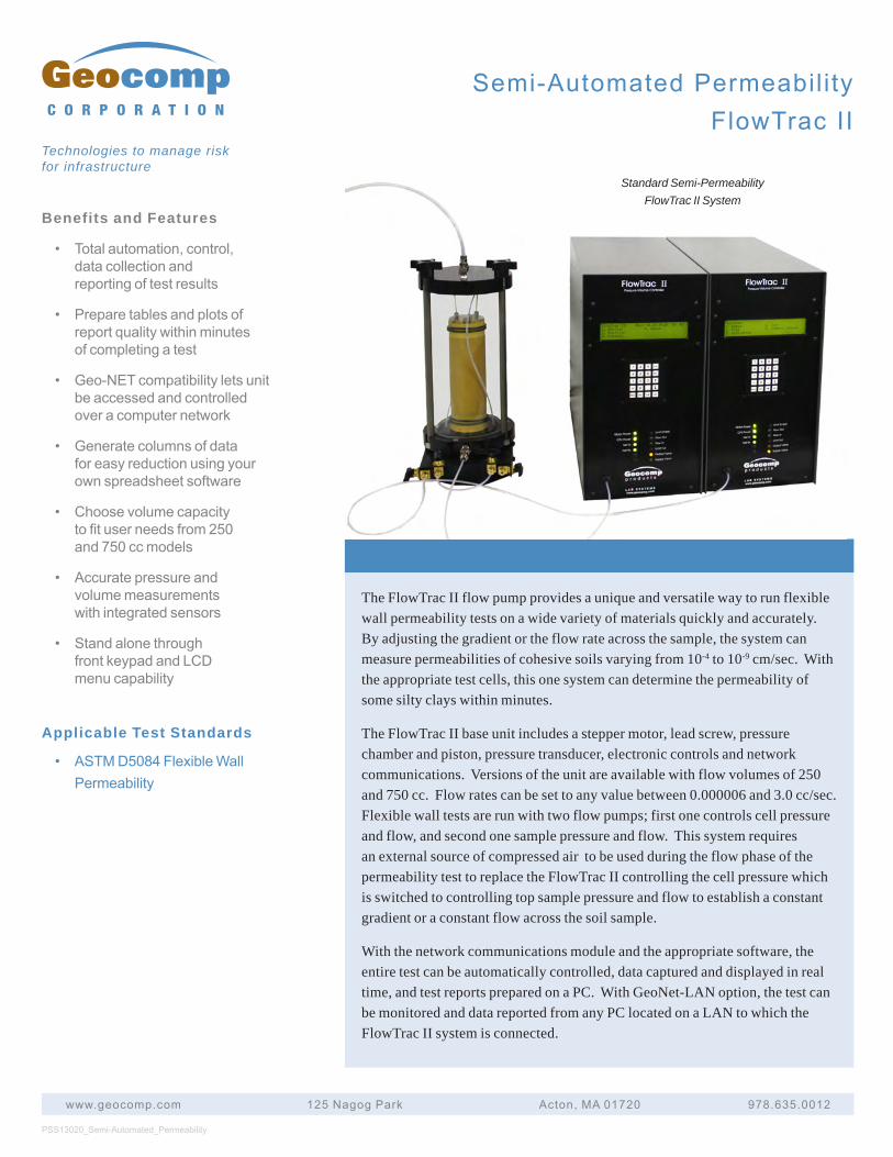
The FlowTrac II flow pump provides a unique and versatile way to run flexible wall permeability tests on a wide variety of materials quickly and accurately. By adjusting the gradient or the flow rate across the sample, the system can measure permeabilities of cohesive soils varying from 10-4 to 10-9 cm/sec. With the appropriate test cells, this one system can determine the permeability of some silty clays within minutes.
The FlowTrac II base unit includes a stepper motor, lead screw, pressure chamber and piston, pressure transducer, electronic controls and network communications. Versions of the unit are available with flow volumes of 250 and 750 cc. Flow rates can be set to any value between 0.000006 and 3.0 cc/sec. Flexible wall tests are run with two flow pumps; first one controls cell pressure and flow, and second one sample pressure and flow. This system requires an external source of compressed air to be used during the flow phase of the permeability test to replace the FlowTrac II controlling the cell pressure which is switched to controlling top sample pressure and flow to establish a constant gradient or a constant flow across the soil sample.
With the network communications module and the appropriate software, the entire test can be automatically controlled, data captured and displayed in real time, and test reports prepared on a PC. With GeoNet-LAN option, the test can be monitored and data reported from any PC located on a LAN to which the FlowTrac II system is connected.
PSS13020_Semi-Automated_Permeability
www.geocomp.com 125NagogPark Acton,MA01720 978.635.0012
C O R P O R A T I O N
Technologies to manage risk for infrastructure
Standard Semi-Permeability FlowTrac II System
Semi-AutomatedPermeabil ityFlowTracII
Semi-AutomatedPermeabil ityFlowTracII
www.geocomp.com 125NagogPark Acton,MA01720 978.635.0012
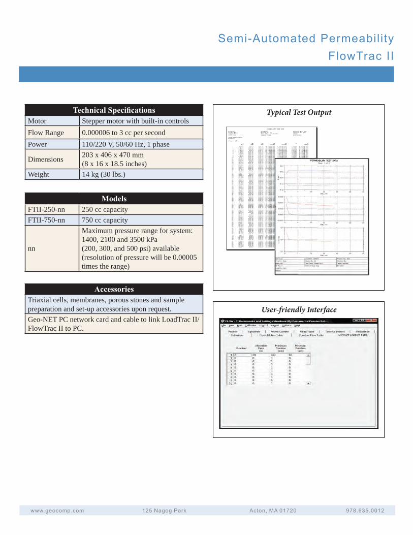
Technical Specifi cationsMotor Stepper motor with built-in controlsFlow Range 0.000006 to 3 cc per secondPower 110/220 V, 50/60 Hz, 1 phase
Dimensions 203 x 406 x 470 mm(8 x 16 x 18.5 inches)
Weight 14 kg (30 lbs.)
Typical Test Output
User-friendly Interface
ModelsFTII-250-nn 250 cc capacityFTII-750-nn 750 cc capacity
nn
Maximum pressure range for system: 1400, 2100 and 3500 kPa (200, 300, and 500 psi) available (resolution of pressure will be 0.00005 times the range)
AccessoriesTriaxial cells, membranes, porous stones and sample preparation and set-up accessories upon request.Geo-NET PC network card and cable to link LoadTrac II/FlowTrac II to PC.
C o m p o n e n t s & A c c e s s o r i e s
Loadtrac II - Loadframe
Loadtrac III - Loadframe
Flowatrac II – Pressure Volume Control
Unconfined Accessories for Loadtrac II & III
California Bearing Ratio
Geolog Acquisition System
Consolidation Cells
Triaxial Cell 3400
Triaxial Cell 3500
Triaxial Cell 3600
Pressure Panel
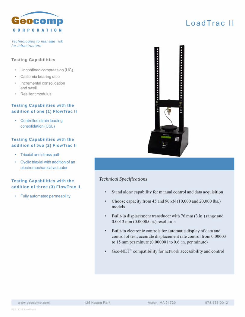
Testing Capabilities
• Unconfinedcompression(UC)• Californiabearingratio• Incrementalconsolidation
andswell• Resilientmodulus
Testing Capabilities with the addition of one (1) FlowTrac II
• Controlledstrainloadingconsolidation(CSL)
Testing Capabilities with the addition of two (2) FlowTrac II
• Triaxialandstresspath
• Cyclictriaxialwithadditionofanelectromechanicalactuator
Testing Capabilities with the addition of three (3) FlowTrac II
• Fullyautomatedpermeability
PSS13034_LoadTracII
www.geocomp.com 125NagogPark Acton,MA01720 978.635.0012
C O R P O R A T I O N
Technologies to manage risk for infrastructure
LoadTrac I I
Technical Specifications
• Standalonecapabilityformanualcontrolanddataacquisition
• Choosecapacityfrom45and90kN(10,000and20,000lbs.)models
• Built-indisplacementtransducerwith76mm(3in.)rangeand0.0013mm(0.00005in.)resolution
• Built-inelectroniccontrolsforautomaticdisplayofdataandcontroloftest;accuratedisplacementratecontrolfrom0.00003to15mmperminute(0.000001to0.6in.perminute)
• Geo-NET™compatibilityfornetworkaccessibilityandcontrol
Testing Capabilities
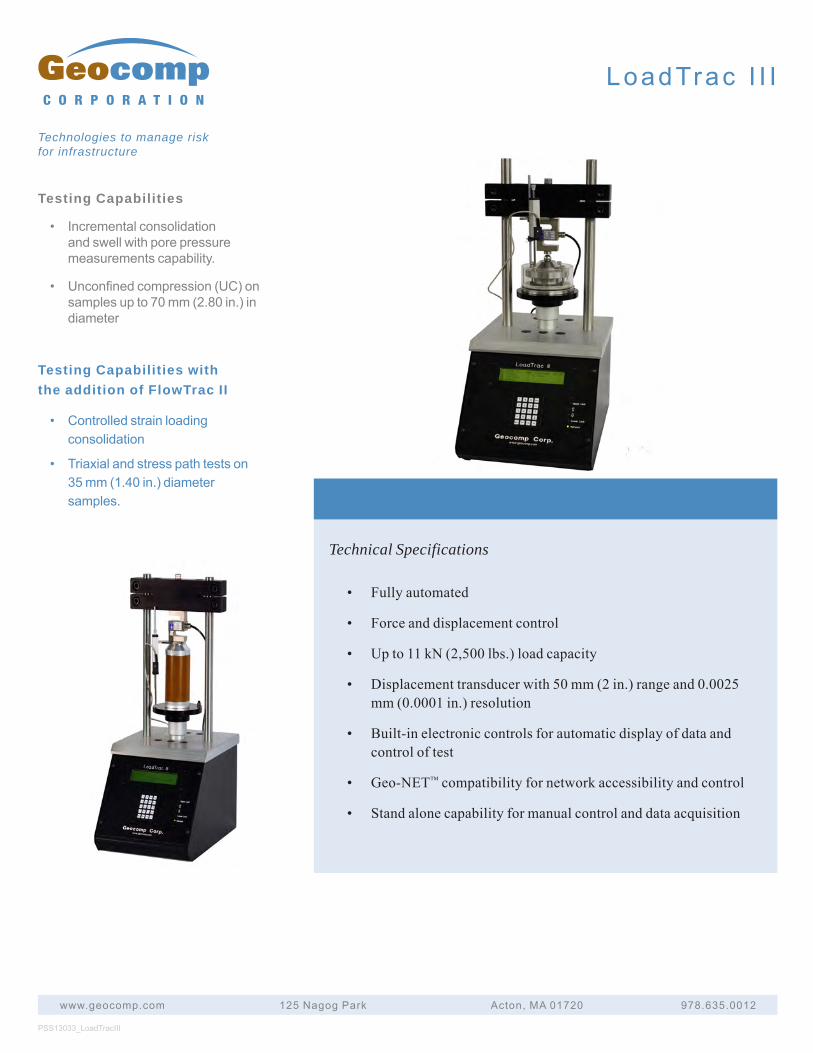
• Incrementalconsolidationandswellwithporepressuremeasurementscapability.
• Unconfinedcompression(UC)onsamplesupto70mm(2.80in.)indiameter
Testing Capabilities with the addition of FlowTrac II
• Controlledstrainloadingconsolidation
• Triaxialandstresspathtestson35mm(1.40in.)diametersamples.
PSS13033_LoadTracIII
www.geocomp.com 125NagogPark Acton,MA01720 978.635.0012
C O R P O R A T I O N
Technologies to manage risk for infrastructure
LoadTrac I I I
Technical Specifications
• Fullyautomated
• Forceanddisplacementcontrol
• Upto11kN(2,500lbs.)loadcapacity
• Displacementtransducerwith50mm(2in.)rangeand0.0025mm(0.0001in.)resolution
• Built-inelectroniccontrolsforautomaticdisplayofdataandcontroloftest
• Geo-NET™compatibilityfornetworkaccessibilityandcontrol
• Standalonecapabilityformanualcontrolanddataacquisition
Testing Capabilities
• FullyAutomatedPermeability
• Semi-AutomatedPermeability
• RoweCellHydraulicConsolidation
Testing Capabilities with the addition of LoadTrac II
• TriaxialandStressPath
• FullyAutomatedPermeability
• CyclicTriaxialwithElecromechanicalActuator
PSS13032_FlowTracII
www.geocomp.com 125NagogPark Acton,MA01720 978.635.0012
C O R P O R A T I O N
Technologies to manage risk for infrastructure
F lowTrac I I
Technical Specifications
• Fullautomationforcontrolofvolumeandpressure
• Standaloneorcomputercontrolunit
• Pressurecapacityof1400kPa(200psi)standard
• Upto3500kPa(500psi)perrequest
• Pressureresolutionof0.00005timesthemax.range
• Pumpcapacity250ccstandard.750ccuponrequest
• Flowrangefrom0.000006to3ccpersecond
• Volumeaccuracyof1mm3
• Limitmicro-switchestopreventpumppistonovertravel
• Embeddedcontroller
• Integratedsignalconditioning,dataacquisition
• Built-insolenoidvalvesfortruefullautomation
• ArcnetnetworkandcommunicationwithPCandotherunits
• Remotenetworkaccess,monitoring,andcontrol
• Doesnotrequirecompressedair
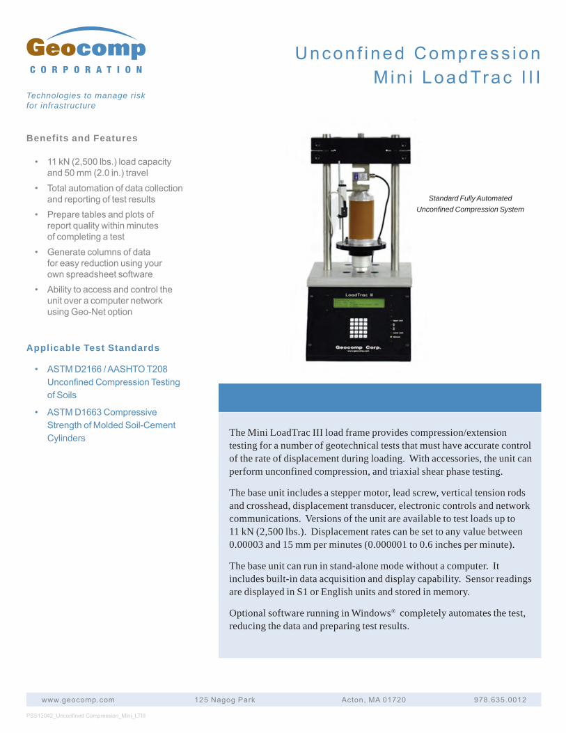
Benefits and Features
• 11 kN (2,500 lbs.) load capacityand 50 mm (2.0 in.) travel
• Total automation of data collectionand reporting of test results
• Prepare tables and plots ofreport quality within minutesof completing a test
• Generate columns of datafor easy reduction using yourown spreadsheet software
• Ability to access and control theunit over a computer networkusing Geo-Net option
Applicable Test Standards
• ASTM D2166 / AASHTO T208Unconfined Compression Testingof Soils
• ASTM D1663 CompressiveStrength of Molded Soil-CementCylinders
PSS13042_Unconfi ned Compression_Mini_LTIII
www.geocomp.com 125 Nagog Park Acton, MA 01720 978.635.0012
C O R P O R A T I O N
Technologies to manage risk for infrastructure
Uncon f ined Compress ionMin i LoadTrac I I I
The Mini LoadTrac III load frame provides compression/extension testing for a number of geotechnical tests that must have accurate control of the rate of displacement during loading. With accessories, the unit can perform unconfined compression, and triaxial shear phase testing.
The base unit includes a stepper motor, lead screw, vertical tension rods and crosshead, displacement transducer, electronic controls and network communications. Versions of the unit are available to test loads up to 11 kN (2,500 lbs.). Displacement rates can be set to any value between 0.00003 and 15 mm per minutes (0.000001 to 0.6 inches per minute).
The base unit can run in stand-alone mode without a computer. It includes built-in data acquisition and display capability. Sensor readings are displayed in S1 or English units and stored in memory.
Optional software running in Windows® completely automates the test, reducing the data and preparing test results.
Standard Fully Automated Unconfined Compression System
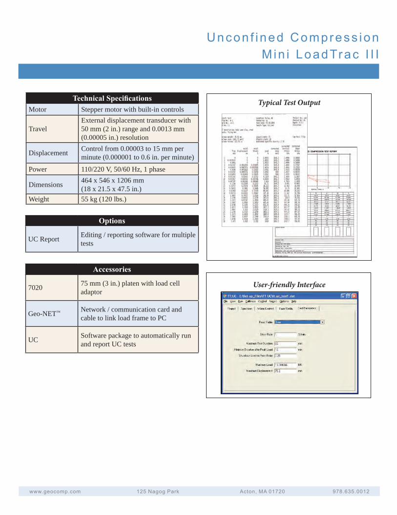
Uncon f ined Compress ionMin i LoadTrac I I I
www.geocomp.com 125 Nagog Park Acton, MA 01720 978.635.0012
Typical Test OutputTechnical Specifi cationsMotor Stepper motor with built-in controls
TravelExternal displacement transducer with 50 mm (2 in.) range and 0.0013 mm (0.00005 in.) resolution
Displacement Control from 0.00003 to 15 mm per minute (0.000001 to 0.6 in. per minute)
Power 110/220 V, 50/60 Hz, 1 phase
Dimensions 464 x 546 x 1206 mm(18 x 21.5 x 47.5 in.)
Weight 55 kg (120 lbs.)
User-friendly Interface
Options
UC Report Editing / reporting software for multiple tests
Accessories
7020 75 mm (3 in.) platen with load cell adaptor
Geo-NET™ Network / communication card and cable to link load frame to PC
UC Software package to automatically run and report UC tests
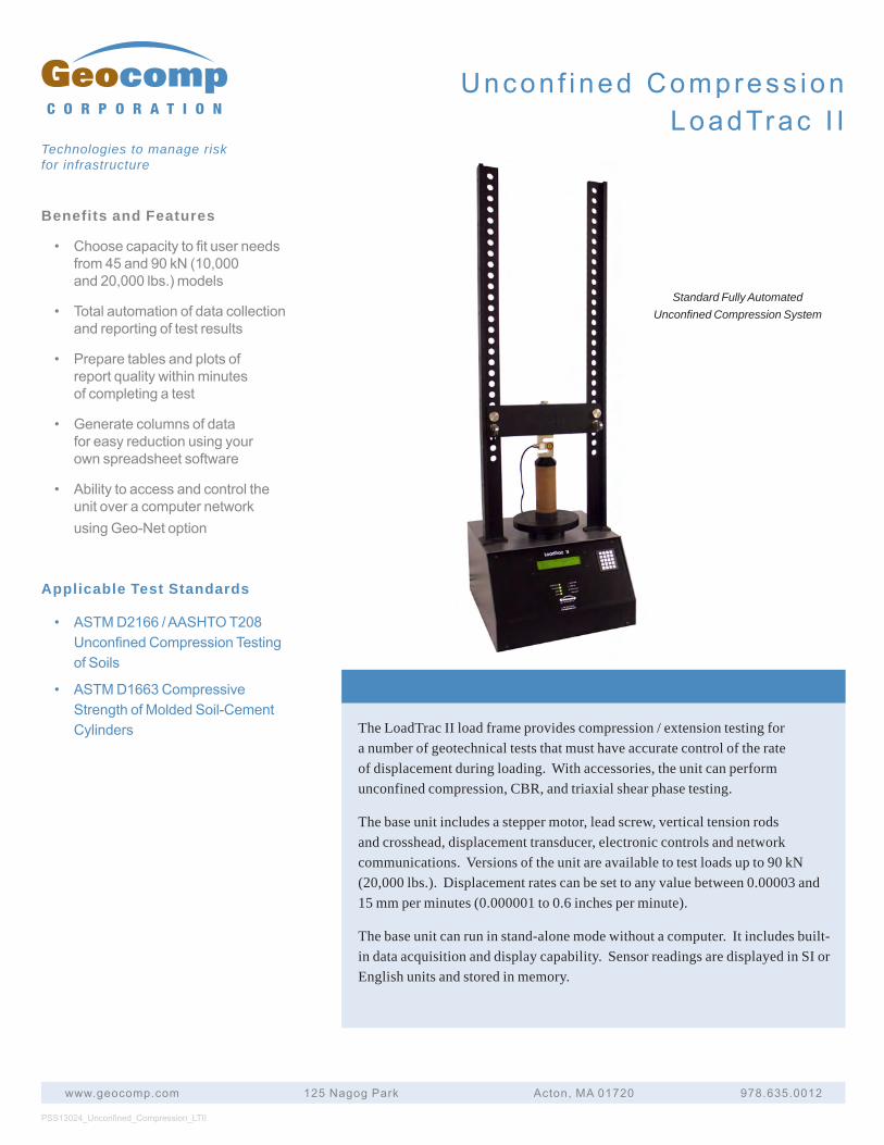
Benefits and Features
• Choosecapacitytofituserneedsfrom45and90kN(10,000and20,000lbs.)models
• Totalautomationofdatacollectionandreportingoftestresults
• Preparetablesandplotsofreportqualitywithinminutesofcompletingatest
• Generatecolumnsofdataforeasyreductionusingyourownspreadsheetsoftware
• AbilitytoaccessandcontroltheunitoveracomputernetworkusingGeo-Netoption
Applicable Test Standards
• ASTMD2166/AASHTOT208UnconfinedCompressionTestingofSoils
• ASTMD1663CompressiveStrengthofMoldedSoil-CementCylinders The LoadTrac II load frame provides compression / extension testing for
a number of geotechnical tests that must have accurate control of the rate of displacement during loading. With accessories, the unit can perform unconfined compression, CBR, and triaxial shear phase testing.
The base unit includes a stepper motor, lead screw, vertical tension rods and crosshead, displacement transducer, electronic controls and network communications. Versions of the unit are available to test loads up to 90 kN (20,000 lbs.). Displacement rates can be set to any value between 0.00003 and 15 mm per minutes (0.000001 to 0.6 inches per minute).
The base unit can run in stand-alone mode without a computer. It includes built-in data acquisition and display capability. Sensor readings are displayed in SI or English units and stored in memory.
PSS13024_Unconfined_Compression_LTII
www.geocomp.com 125NagogPark Acton,MA01720 978.635.0012
C O R P O R A T I O N
Technologies to manage risk for infrastructure
Standard Fully Automated Unconfined Compression System
Uncon f ined Compress ionLoadTrac I I
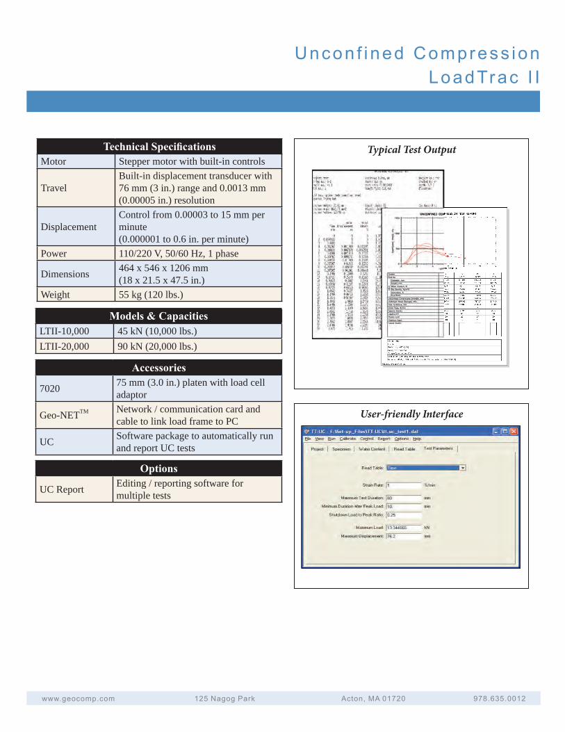
Uncon f ined Compress ionLoadTrac I I
www.geocomp.com 125NagogPark Acton,MA01720 978.635.0012
Technical Specifi cationsMotor Stepper motor with built-in controls
TravelBuilt-in displacement transducer with 76 mm (3 in.) range and 0.0013 mm (0.00005 in.) resolution
DisplacementControl from 0.00003 to 15 mm per minute (0.000001 to 0.6 in. per minute)
Power 110/220 V, 50/60 Hz, 1 phase
Dimensions 464 x 546 x 1206 mm(18 x 21.5 x 47.5 in.)
Weight 55 kg (120 lbs.)
Typical Test Output
User-friendly Interface
Models & CapacitiesLTII-10,000 45 kN (10,000 lbs.)LTII-20,000 90 kN (20,000 lbs.)
Accessories
7020 75 mm (3.0 in.) platen with load cell adaptor
Geo-NETTM Network / communication card and cable to link load frame to PC
UC Software package to automatically run and report UC tests
Options
UC Report Editing / reporting software for multiple tests
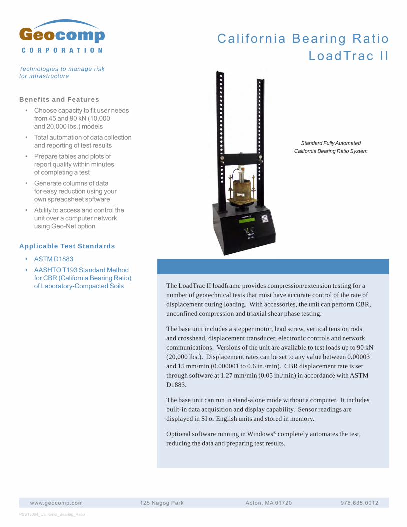
Benefits and Features• Choosecapacitytofituserneeds
from45and90kN(10,000and20,000lbs.)models
• Totalautomationofdatacollectionandreportingoftestresults
• Preparetablesandplotsofreportqualitywithinminutesofcompletingatest
• Generatecolumnsofdataforeasyreductionusingyourownspreadsheetsoftware
• AbilitytoaccessandcontroltheunitoveracomputernetworkusingGeo-Netoption
Applicable Test Standards
• ASTMD1883• AASHTOT193StandardMethod
forCBR(CaliforniaBearingRatio)ofLaboratory-CompactedSoils The LoadTrac II loadframe provides compression/extension testing for a
number of geotechnical tests that must have accurate control of the rate of displacement during loading. With accessories, the unit can perform CBR, unconfined compression and triaxial shear phase testing.
The base unit includes a stepper motor, lead screw, vertical tension rods and crosshead, displacement transducer, electronic controls and network communications. Versions of the unit are available to test loads up to 90 kN (20,000 lbs.). Displacement rates can be set to any value between 0.00003 and 15 mm/min (0.000001 to 0.6 in./min). CBR displacement rate is set through software at 1.27 mm/min (0.05 in./min) in accordance with ASTM D1883.
The base unit can run in stand-alone mode without a computer. It includes built-in data acquisition and display capability. Sensor readings are displayed in SI or English units and stored in memory.
Optional software running in Windows® completely automates the test, reducing the data and preparing test results.
PSS13004_California_Bearing_Ratio
www.geocomp.com 125NagogPark Acton,MA01720 978.635.0012
C O R P O R A T I O N
Technologies to manage risk for infrastructure
Ca l i f o rn ia Bear ing Ra t ioLoadTrac I I
Standard Fully Automated California Bearing Ratio System
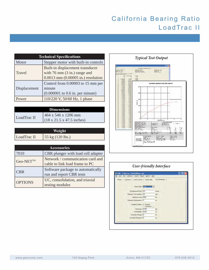
Ca l i f o rn ia Bear ing Ra t ioLoadTrac I I
Technical Specifi cationsMotor Stepper motor with built-in controls
TravelBuilt-in displacement transducer with 76 mm (3 in.) range and 0.0013 mm (0.00005 in.) resolution
DisplacementControl from 0.00003 to 15 mm per minute (0.000001 to 0.6 in. per minute)
Power 110/220 V, 50/60 Hz, 1 phase
Dimensions
LoadTrac II 464 x 546 x 1206 mm(18 x 21.5 x 47.5 inches)
WeightLoadTrac II 55 kg (120 lbs.)
Accessories7010 CBR plunger with load cell adapter
Geo-NETTM Network / communication card and cable to link load frame to PC
CBR Software package to automatically run and report CBR tests
OPTIONS UC, consolidation, and triaxial testing modules
User-friendly Interface
www.geocomp.com 125NagogPark Acton,MA01720 978.635.0012
Typical Test Output
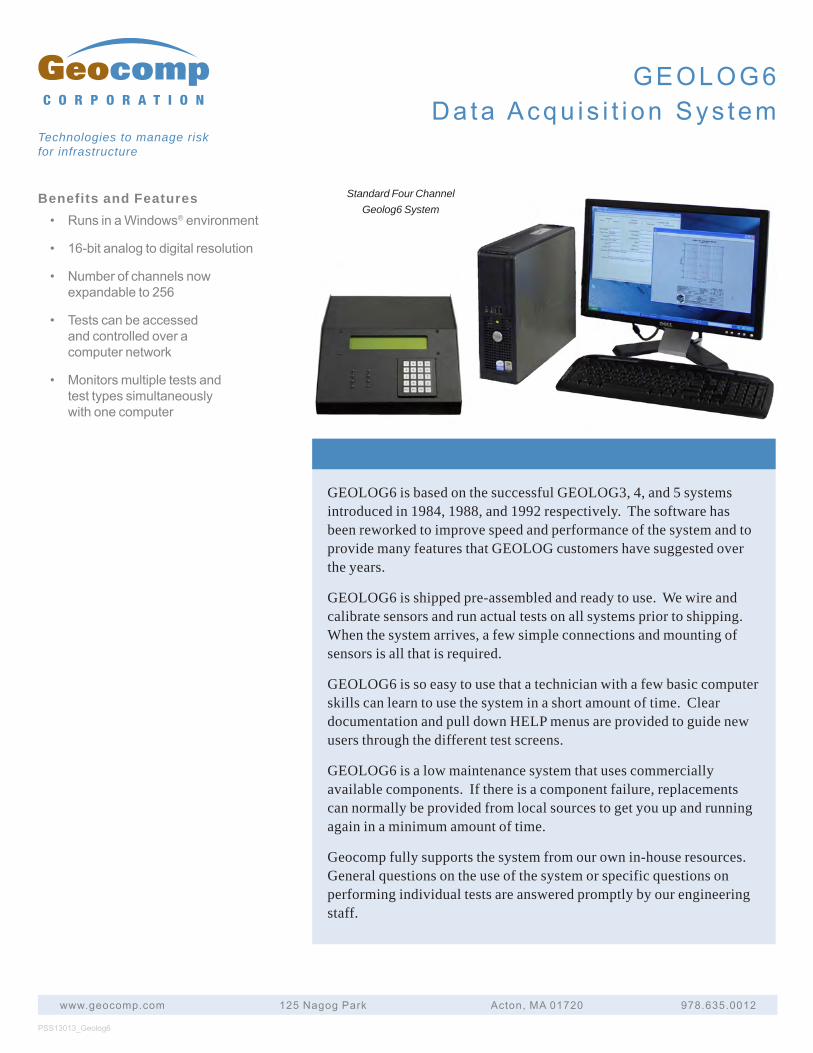
Benefits and Features• RunsinaWindows®environment
• 16-bitanalogtodigitalresolution
• Numberofchannelsnowexpandableto256
• Testscanbeaccessedandcontrolledoveracomputernetwork
• Monitorsmultipletestsandtesttypessimultaneouslywithonecomputer
GEOLOG6 is based on the successful GEOLOG3, 4, and 5 systems introduced in 1984, 1988, and 1992 respectively. The software has been reworked to improve speed and performance of the system and to provide many features that GEOLOG customers have suggested over the years.
GEOLOG6 is shipped pre-assembled and ready to use. We wire and calibrate sensors and run actual tests on all systems prior to shipping. When the system arrives, a few simple connections and mounting of sensors is all that is required.
GEOLOG6 is so easy to use that a technician with a few basic computer skills can learn to use the system in a short amount of time. Clear documentation and pull down HELP menus are provided to guide new users through the different test screens.
GEOLOG6 is a low maintenance system that uses commercially available components. If there is a component failure, replacements can normally be provided from local sources to get you up and running again in a minimum amount of time.
Geocomp fully supports the system from our own in-house resources. General questions on the use of the system or specific questions on performing individual tests are answered promptly by our engineering staff.
PSS13013_Geolog6
www.geocomp.com 125NagogPark Acton,MA01720 978.635.0012
C O R P O R A T I O N
Technologies to manage risk for infrastructure
Standard Four Channel Geolog6 System
GEOLOG6Da ta Acqu is i t i on Sys tem
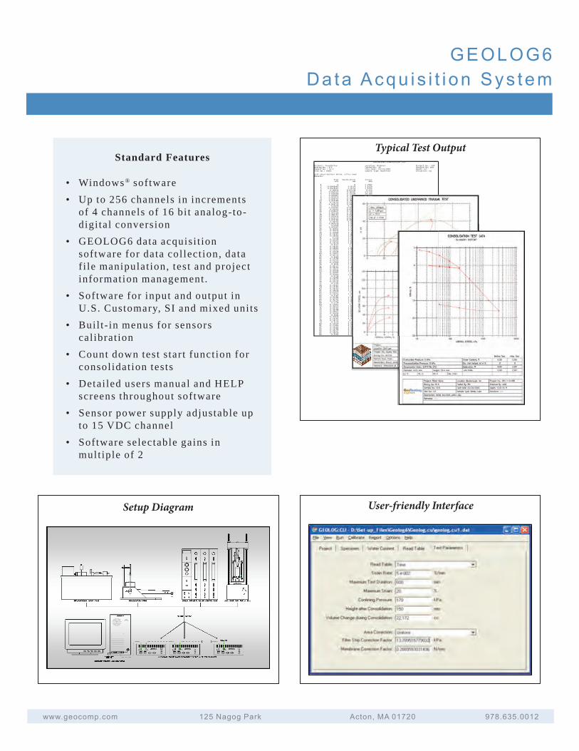
GEOLOG6Da ta Acqu is i t i on Sys tem
www.geocomp.com 125NagogPark Acton,MA01720 978.635.0012
Typical Test Output
User-friendly InterfaceSetup Diagram
Standard Features
• Windows® software• Up to 256 channels in increments
of 4 channels of 16 bi t analog-to-digi tal conversion
• GEOLOG6 data acquisi t ionsoftware for data collect ion, datafi le manipulat ion, test and projectinformation management.
• Software for input and output inU.S. Customary, SI and mixed units
• Buil t- in menus for sensorscal ibrat ion
• Count down test s tar t function forconsolidat ion tests
• Detailed users manual and HELPscreens throughout software
• Sensor power supply adjustable upto 15 VDC channel
• Software selectable gains inmult iple of 2
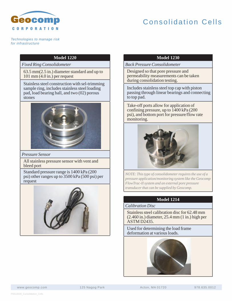
PSS13030_Consolidation_Cells
www.geocomp.com 125 Nagog Park Acton, MA 01720 978.635.0012
C O R P O R A T I O N
Technologies to manage risk for infrastructure
Conso l i da t i on Ce l l s
Model 1220Fixed Ring Consolidometer63.5 mm(2.5 in.) diameter standard and up to 101 mm (4.0 in.) per request
Stainless steel construction with sel-trimming sample ring, includes stainless steel loading pad, load bearing ball, and two (02) porous stones
Pressure SensorAll stainless pressure sensor with vent and bleed portStandard pressure range is 1400 kPa (200 psi) other ranges up to 3500 kPa (500 psi) per request
Model 1230Back Pressure ConsolidometerDesigned so that pore pressure and permeability measurements can be taken during consolidation testing.
Includes stainless steel top cap with piston passing through linear bearings and connecting to top pad.
Take-off ports allow for application of confining pressure, up to 1400 kPa (200 psi), and bottom port for pressure/flow rate monitoring.
NOTE: This type of consolidometer requires the use of a pressure application/monitoring system like the Geocomp FlowTrac-II system and an external pore pressure transducer that can be supplied by Geocomp.
Model 1214Calibration DiscStainless steel calibration disc for 62.48 mm (2.460 in.) diameter, 25.4 mm (1 in.) high per ASTM D2435.Used for determining the load frame deformation at various loads.
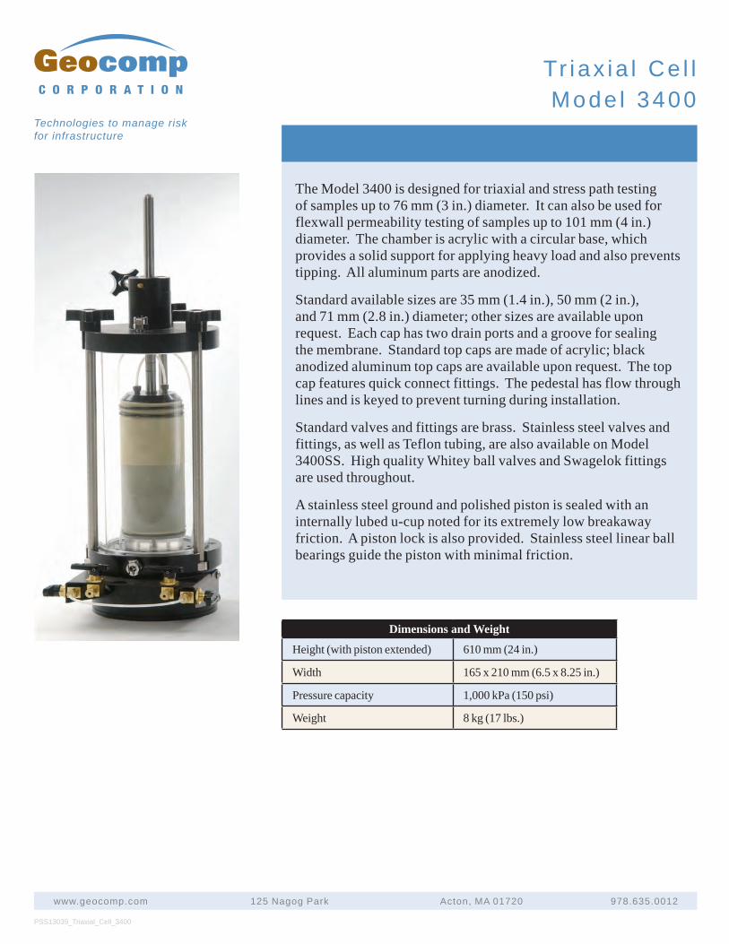
PSS13039_Triaxial_Cell_3400
www.geocomp.com 125 Nagog Park Acton, MA 01720 978.635.0012
C O R P O R A T I O N
Technologies to manage risk for infrastructure
Tr iax ia l Ce l lMode l 3400
The Model 3400 is designed for triaxial and stress path testing of samples up to 76 mm (3 in.) diameter. It can also be used for flexwall permeability testing of samples up to 101 mm (4 in.) diameter. The chamber is acrylic with a circular base, which provides a solid support for applying heavy load and also prevents tipping. All aluminum parts are anodized.
Standard available sizes are 35 mm (1.4 in.), 50 mm (2 in.), and 71 mm (2.8 in.) diameter; other sizes are available upon request. Each cap has two drain ports and a groove for sealing the membrane. Standard top caps are made of acrylic; black anodized aluminum top caps are available upon request. The top cap features quick connect fittings. The pedestal has flow through lines and is keyed to prevent turning during installation.
Standard valves and fittings are brass. Stainless steel valves and fittings, as well as Teflon tubing, are also available on Model 3400SS. High quality Whitey ball valves and Swagelok fittings are used throughout.
A stainless steel ground and polished piston is sealed with an internally lubed u-cup noted for its extremely low breakaway friction. A piston lock is also provided. Stainless steel linear ball bearings guide the piston with minimal friction.
Dimensions and Weight
Height (with piston extended) 610 mm (24 in.)
Width 165 x 210 mm (6.5 x 8.25 in.)
Pressure capacity 1,000 kPa (150 psi)
Weight 8 kg (17 lbs.)
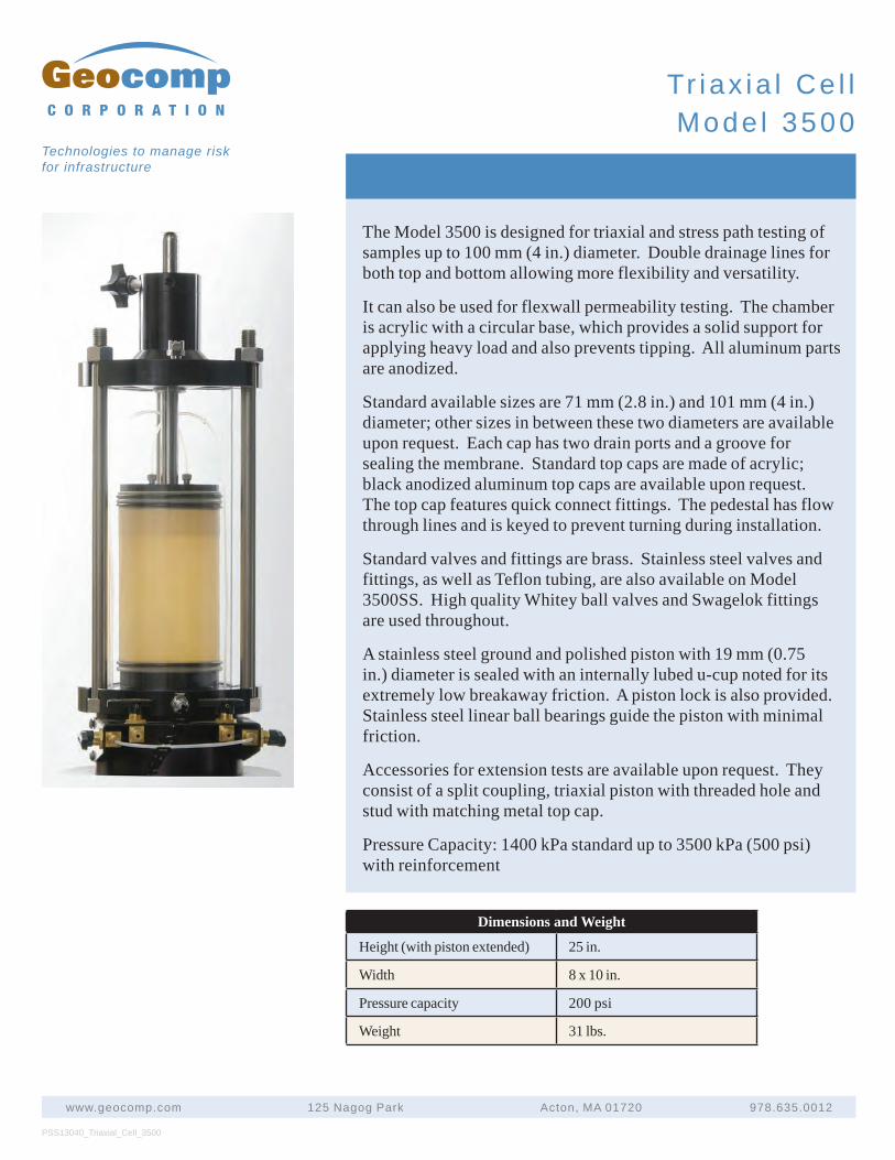
PSS13040_Triaxial_Cell_3500
www.geocomp.com 125 Nagog Park Acton, MA 01720 978.635.0012
C O R P O R A T I O N
Technologies to manage risk for infrastructure
Tr iax ia l Ce l lMode l 3500
The Model 3500 is designed for triaxial and stress path testing of samples up to 100 mm (4 in.) diameter. Double drainage lines for both top and bottom allowing more flexibility and versatility.
It can also be used for flexwall permeability testing. The chamber is acrylic with a circular base, which provides a solid support for applying heavy load and also prevents tipping. All aluminum parts are anodized.
Standard available sizes are 71 mm (2.8 in.) and 101 mm (4 in.) diameter; other sizes in between these two diameters are available upon request. Each cap has two drain ports and a groove for sealing the membrane. Standard top caps are made of acrylic; black anodized aluminum top caps are available upon request. The top cap features quick connect fittings. The pedestal has flow through lines and is keyed to prevent turning during installation.
Standard valves and fittings are brass. Stainless steel valves and fittings, as well as Teflon tubing, are also available on Model 3500SS. High quality Whitey ball valves and Swagelok fittings are used throughout.
A stainless steel ground and polished piston with 19 mm (0.75 in.) diameter is sealed with an internally lubed u-cup noted for its extremely low breakaway friction. A piston lock is also provided. Stainless steel linear ball bearings guide the piston with minimal friction.
Accessories for extension tests are available upon request. They consist of a split coupling, triaxial piston with threaded hole and stud with matching metal top cap.
Pressure Capacity: 1400 kPa standard up to 3500 kPa (500 psi) with reinforcement
Dimensions and Weight
Height (with piston extended) 25 in.
Width 8 x 10 in.
Pressure capacity 200 psi
Weight 31 lbs.
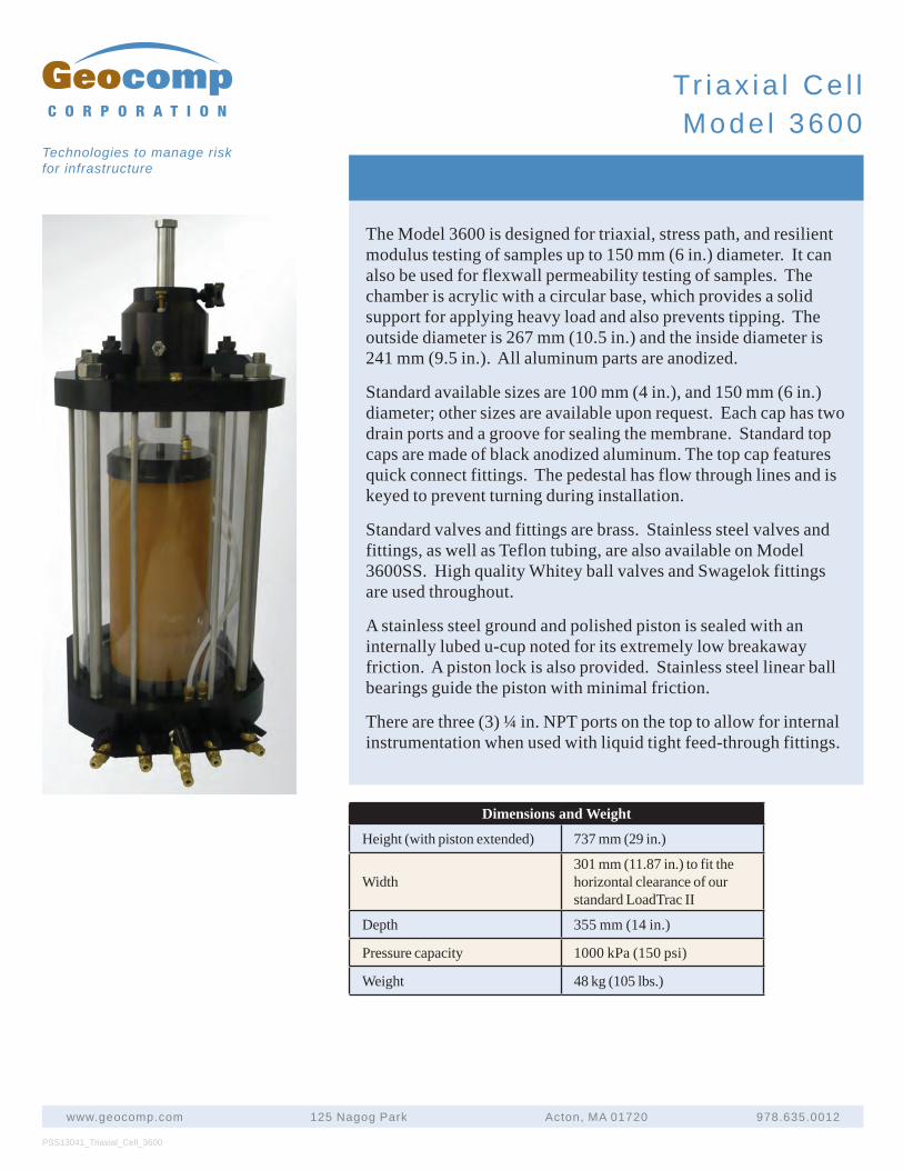
PSS13041_Triaxial_Cell_3600
www.geocomp.com 125 Nagog Park Acton, MA 01720 978.635.0012
C O R P O R A T I O N
Technologies to manage risk for infrastructure
Tr iax ia l Ce l lMode l 3600
The Model 3600 is designed for triaxial, stress path, and resilient modulus testing of samples up to 150 mm (6 in.) diameter. It can also be used for flexwall permeability testing of samples. The chamber is acrylic with a circular base, which provides a solid support for applying heavy load and also prevents tipping. The outside diameter is 267 mm (10.5 in.) and the inside diameter is 241 mm (9.5 in.). All aluminum parts are anodized.
Standard available sizes are 100 mm (4 in.), and 150 mm (6 in.) diameter; other sizes are available upon request. Each cap has two drain ports and a groove for sealing the membrane. Standard top caps are made of black anodized aluminum. The top cap features quick connect fittings. The pedestal has flow through lines and is keyed to prevent turning during installation.
Standard valves and fittings are brass. Stainless steel valves and fittings, as well as Teflon tubing, are also available on Model 3600SS. High quality Whitey ball valves and Swagelok fittings are used throughout.
A stainless steel ground and polished piston is sealed with an internally lubed u-cup noted for its extremely low breakaway friction. A piston lock is also provided. Stainless steel linear ball bearings guide the piston with minimal friction.
There are three (3) ¼ in. NPT ports on the top to allow for internal instrumentation when used with liquid tight feed-through fittings.
Dimensions and Weight
Height (with piston extended) 737 mm (29 in.)
Width301 mm (11.87 in.) to fit the horizontal clearance of our standard LoadTrac II
Depth 355 mm (14 in.)
Pressure capacity 1000 kPa (150 psi)
Weight 48 kg (105 lbs.)
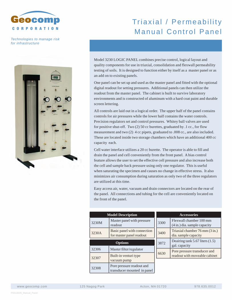
PSS13035_Manual_Panel
www.geocomp.com 125 Nagog Park Acton, MA 01720 978.635.0012
C O R P O R A T I O N
Technologies to manage risk for infrastructure
Tr iax ia l / Pe rmeab i l i t yManua l Con t ro l Pane l
Model 3230 LOGIC PANEL combines precise control, logical layout and quality components for use in triaxial, consolidation and flexwall permeability testing of soils. It is designed to function either by itself as a master panel or as an add on to existing panels.
One panel can be set up and used as the master panel and fitted with the optional digital readout for setting pressures. Additional panels can then utilize the readout from the master panel. The cabinet is built to survive laboratory environments and is constructed of aluminum with a hard coat paint and durable screen lettering.
All controls are laid out in a logical order. The upper half of the panel contains controls for air pressures while the lower half contains the water controls. Precision regulators set and control pressures. Whitey ball valves are used for positive shut-off. Two (2) 50 cc burettes, graduated by .1 cc., for flow measurement and two (2) 4 cc pipets, graduated to .008 cc., are also included. These are located inside two storage chambers which have an additional 400 cc capacity each.
Cell water interface utilizes a 20 cc burette. The operator is able to fill and drain the panel and cell conveniently from the front panel. A bias control feature allows the user to set the effective cell pressure and also increase both the cell and sample back pressure using only one regulator. This is useful when saturating the specimen and causes no change in effective stress. It also minimizes air consumption during saturation as only two of the three regulators are utilized at this time.
Easy access air, water, vacuum and drain connectors are located on the rear of the panel. All connections and tubing for the cell are conveniently located on the front of the panel.
Model Description
3230M Master panel with pressure readout
3230A Basic panel with connection for master panel readout
Options
32306 Master fi lter/regulator
32307 Built-in venturi type vacuum pump
32308 Pore pressure readout and transducer mounted in panel
Accessories
3300 Flexwall chamber 100 mm (4 in.) dia. sample capacity
3400 Triaxial chamber 76 mm (3 in.) dia. sample capacity
3872 Deairing tank 5.67 liters (1.5) gal. capacity
6630 Pore pressure transducer and readout with moveable cabinet
F i e l d M e a s u r e m e n t s
iSite Wireless Data Loggers
iSite Highspeed Data Loggers
iNoise for Noise Monitoring
Dynamic Concrete Strain Gages
Dynamic Asphalt Strain Gages
Soil Compression Gages
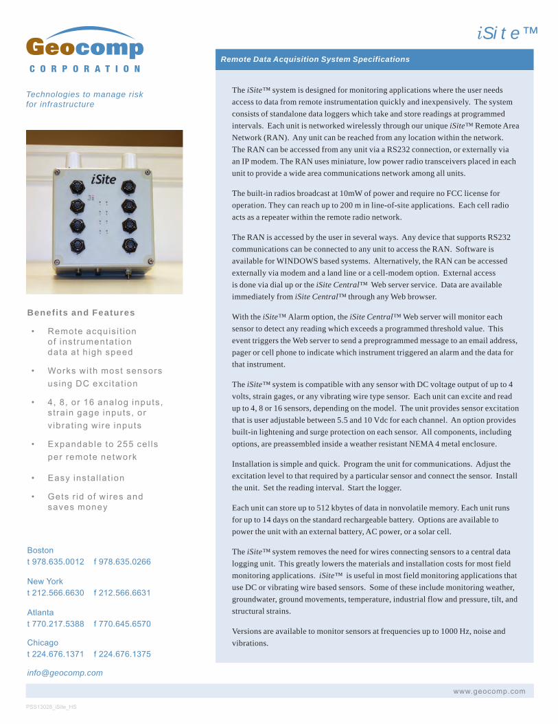
Benefits and Features
• Remoteacquis i t ionof instrumentat iondataat h ighspeed
• Workswi thmost sensorsusingDCexci tat ion
• 4, 8, or 16analoginputs,st ra ingageinputs, orv ibrat ingwireinputs
• Expandableto255cel lsperremotenetwork
• Easyinsta l la t ion
• Getsr id of wiresandsavesmoney
Remote Data Acquisition System Specifications
The iSite™ system is designed for monitoring applications where the user needs access to data from remote instrumentation quickly and inexpensively. The system consists of standalone data loggers which take and store readings at programmed intervals. Each unit is networked wirelessly through our unique iSite™ Remote Area Network (RAN). Any unit can be reached from any location within the network. The RAN can be accessed from any unit via a RS232 connection, or externally via an IP modem. The RAN uses miniature, low power radio transceivers placed in each unit to provide a wide area communications network among all units.
The built-in radios broadcast at 10mW of power and require no FCC license for operation. They can reach up to 200 m in line-of-site applications. Each cell radio acts as a repeater within the remote radio network.
The RAN is accessed by the user in several ways. Any device that supports RS232 communications can be connected to any unit to access the RAN. Software is available for WINDOWS based systems. Alternatively, the RAN can be accessed externally via modem and a land line or a cell-modem option. External access is done via dial up or the iSite Central™ Web server service. Data are available immediately from iSite Central™ through any Web browser.
With the iSite™ Alarm option, the iSite Central™ Web server will monitor each sensor to detect any reading which exceeds a programmed threshold value. This event triggers the Web server to send a preprogrammed message to an email address, pager or cell phone to indicate which instrument triggered an alarm and the data for that instrument.
The iSite™ system is compatible with any sensor with DC voltage output of up to 4 volts, strain gages, or any vibrating wire type sensor. Each unit can excite and read up to 4, 8 or 16 sensors, depending on the model. The unit provides sensor excitation that is user adjustable between 5.5 and 10 Vdc for each channel. An option provides built-in lightening and surge protection on each sensor. All components, including options, are preassembled inside a weather resistant NEMA 4 metal enclosure.
Installation is simple and quick. Program the unit for communications. Adjust the excitation level to that required by a particular sensor and connect the sensor. Install the unit. Set the reading interval. Start the logger.
Each unit can store up to 512 kbytes of data in nonvolatile memory. Each unit runs for up to 14 days on the standard rechargeable battery. Options are available to power the unit with an external battery, AC power, or a solar cell.
The iSite™ system removes the need for wires connecting sensors to a central data logging unit. This greatly lowers the materials and installation costs for most field monitoring applications. iSite™ is useful in most field monitoring applications that use DC or vibrating wire based sensors. Some of these include monitoring weather, groundwater, ground movements, temperature, industrial flow and pressure, tilt, and structural strains.
Versions are available to monitor sensors at frequencies up to 1000 Hz, noise and vibrations.
PSS13028_iSite_HS
C O R P O R A T I O N
Technologies to manage risk for infrastructure
iS i te™
Bostont978.635.0012 f978.635.0266
NewYorkt212.566.6630 f212.566.6631
Atlantat770.217.5388 f770.645.6570
Chicagot224.676.1371 f224.676.1375
www.geocomp.com
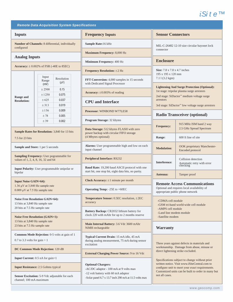
Remote Data Acquisition System Specifications
iS i te™
www.geocomp.com
Inputs
Number of Channels: 8 differential, individually configured
Analog Inputs
Accuracy: ± 0.002% of FSR (-40E to 85EC)
Range and Resolution:
Input Range(mV)
Resolution(μV)
± 2500 0.15± 1250 0.075± 625 0.037± 313 0.019± 156 0.009± 78 0.005± 39 0.002
Sample Rates for Resolution: 3,840 for 13 bits
7.5 for 23 bits
Sample and Store: 1 per 5 seconds
Sampling Frequency: User pogrammable for values of 1, 2, 4, 8, 16, 32 and 64
Input Polarity: User programmable unipolar or bipolar
Input Noise GAIN=64):1.36 μV at 3,840 Hz sample rate0.009 μV at 7.5 Hz sample rate
Noise Free Resolution GAIN=64):13 bits at 3,840 Hz sample rate20 bits at 7.5 Hz sample rate
Noise Free Resolution (GAIN=1):13 bits at 3,840 Hz sample rate23 bits at 7.5 Hz sample rate
Common Mode Rejection: 0-5 volts at gain of 1
0.7 to 3.3 volts for gain > 1
DC Common Mode Rejection: 120 dB
Input Current: 0.5 nA for gain>1
Input Resistance: 2.5 Gohms typical
Sensor Excitation: 5-9 Vdc adjustable for each channel; 100 mA maximum
Frequency Inputs
Sample Rate:16 kHz
Maximum Frequency: 8,000 Hz
Minimum Frequency: 400 Hz
Frequency Resolution: ±2 Hz
FFT Conversion: 4,000 samples in 15 seconds with Dedicated Signal Processor
Accuracy: ±0.003% of reading
CPU and Interface
Processor: WINBOND W77LE58
Program Storage: 32 kbytes
Data Storage: 512 kbytes FLASH with zero power backup with circular FIFO storage (4 Mbytes optional)
Alarms: User programmable high and low on each input channel
Peripheral Interface: RS232
Baud Rate: 19,200 baud ASCII protocol with one start bit, one stop bit, eight data bits, no parity.
Clock Accuracy: ±1 minute per month
Operating Temp: -25E to +60EC
Temperature Sensor: 0.5EC resolution, ±2EC accuracy
Battery Backup: CR2032 lithium battery for clock 220 with mAhr for up to 2 months reserve
Main Internal Battery: 3.6 Vdc 3600 mAhr NiMH rechargeable
Typical Current Drain: 15 mA idle, 45 mA during analog measurement, 75 mA during sensor excitation
External Charging Power Source: 9 to 16 Vdc
Optional Chargers:-AC/DC adaptor - 100 mA at 9 volts max-12 volt battery with 60 mA adaptor-Solar panel 6.7 x 13.7 inch 290 mA at 11.5 volts max
Sensor Connectors
MIL-C-26482 12-10 size circular bayonet lock connector
Enclosure
Size: 7.8 x 7.8 x 4.7 inches195 x 195 x 120 mm7.1 l (3.2 kgm)
Lightening And Surge Protection (Optional):1st stage: tripolar plasma surge arrestors
2nd stage: SiDactor™ medium voltage surge arrestors
3rd stage: SiDactor™ low voltage surge arrestors
Radio Transceiver (optional)
Frequency:915 MHz ISM band 2 way2.5 GHz Spread Spectrum
Range: 600 ft line of site
Modulation: OOK proprietary Manchester-Encoded protocol
Interference:Collision detectionAutomatic retry with error checking
Antenna: Tamper proof
Remote Access Communications Optional and requires local availability of appropriate public phone network
-CDMA cell module -GSM tri-band world-wide cell module -AMPS cell module -Land line modem module -Satellite modem
Warranty
Three years against defects in materials and workmanship. Damage from abuse, misuse or direct lightening strike excluded.
Specifications subject to change without prior written notice. Visit www.iSiteCentral.com to configure unit to meet your exact requirements. Customized units can be built to order in many but not all cases.
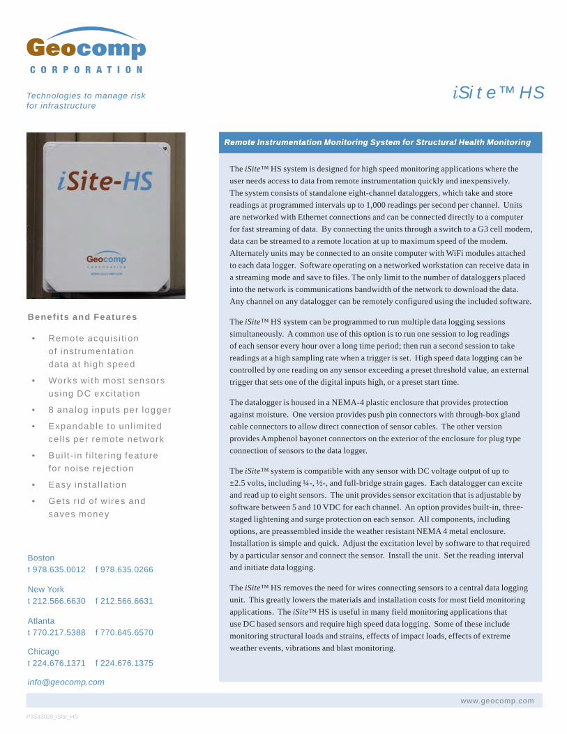
Benefits and Features
• Remote acquis i t ionof instrumentat iondata at h igh speed
• Works wi th most sensorsusing DC exci tat ion
• 8 analog inputs per logger
• Expandable to unl imi tedcel ls per remote network
• Bui l t - in f i l ter ing featurefor noise re ject ion
• Easy insta l la t ion
• Gets r id of wires andsaves money
Remote Instrumentation Monitoring System for Structural Health Monitoring
The iSite™ HS system is designed for high speed monitoring applications where the user needs access to data from remote instrumentation quickly and inexpensively. The system consists of standalone eight-channel dataloggers, which take and store readings at programmed intervals up to 1,000 readings per second per channel. Units are networked with Ethernet connections and can be connected directly to a computer for fast streaming of data. By connecting the units through a switch to a G3 cell modem, data can be streamed to a remote location at up to maximum speed of the modem. Alternately units may be connected to an onsite computer with WiFi modules attached to each data logger. Software operating on a networked workstation can receive data in a streaming mode and save to files. The only limit to the number of dataloggers placed into the network is communications bandwidth of the network to download the data. Any channel on any datalogger can be remotely configured using the included software.
The iSite™ HS system can be programmed to run multiple data logging sessions simultaneously. A common use of this option is to run one session to log readings of each sensor every hour over a long time period; then run a second session to take readings at a high sampling rate when a trigger is set. High speed data logging can be controlled by one reading on any sensor exceeding a preset threshold value, an external trigger that sets one of the digital inputs high, or a preset start time.
The datalogger is housed in a NEMA-4 plastic enclosure that provides protection against moisture. One version provides push pin connectors with through-box gland cable connectors to allow direct connection of sensor cables. The other version provides Amphenol bayonet connectors on the exterior of the enclosure for plug type connection of sensors to the data logger.
The iSite™ system is compatible with any sensor with DC voltage output of up to ±2.5 volts, including ¼-, ½-, and full-bridge strain gages. Each datalogger can excite and read up to eight sensors. The unit provides sensor excitation that is adjustable by software between 5 and 10 VDC for each channel. An option provides built-in, three-staged lightening and surge protection on each sensor. All components, including options, are preassembled inside the weather resistant NEMA 4 metal enclosure. Installation is simple and quick. Adjust the excitation level by software to that required by a particular sensor and connect the sensor. Install the unit. Set the reading interval and initiate data logging.
The iSite™ HS removes the need for wires connecting sensors to a central data logging unit. This greatly lowers the materials and installation costs for most field monitoring applications. The iSite™ HS is useful in many field monitoring applications that use DC based sensors and require high speed data logging. Some of these include monitoring structural loads and strains, effects of impact loads, effects of extreme weather events, vibrations and blast monitoring.
PSS13028_iSite_HS
C O R P O R A T I O N
Technologies to manage risk for infrastructure
iS i te™ HS
Bostont 978.635.0012 f 978.635.0266
New Yorkt 212.566.6630 f 212.566.6631
Atlanta t 770.217.5388 f 770.645.6570
Chicago t 224.676.1371 f 224.676.1375
Remote Instrumentation Monitoring System for Structural Health Monitoring
www.geocomp.com
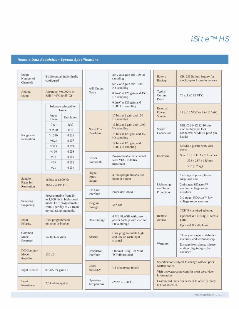
Remote Data Acquisition System Specifications
iS i te™ HS
www.geocomp.com
Inputs Number of Channels
8 differential, individually configured
Analog Inputs
Accuracy: "0.002% of FSR (-40°C to 85°C)
Range and Resolution
Software selected by channel
Input Range Resolution
(mV) (μV)"2500 0.15"1250 0.075"625 0.037"313 0.019"156 0.009"78 0.005"39 0.002"20 0.001
Sample Rates for Resolution
16 bits at 1,000 Hz
18 bits at 150 Hz
Sampling Frequency
Programmable from 25 to 1,000 Hz in high speed mode. User programmable from 1 per day to 25 Hz in normal sampling mode.
Input Polarity
User programmable unipolar or bipolar
Common Mode Rejection
1.2 to 4.05 volts
DC Common Mode Rejection
120 dB
Input Current 0.5 nA for gain >1
Input Resistance 2.5 Gohms typical
A/D Output Noise
3mV at 2 gain and 150 Hz sampling
6mV at 2 gain and 1,000 Hz sampling
0.2mV at 128 gain and 150 Hz sampling
0.6mV at 128 gain and 1,000 Hz sampling
Noise Free Resolution
17 bits at 2 gain and 150 Hz sampling
16 bits at 2 gain and 1,000 Hz sampling
15 bits at 128 gain and 150 Hz sampling
14 bits at 128 gain and 1,000 Hz sampling
Sensor Excitation
Programmable per channel 5-10 VDC, 100 mA maximum
Digital Input/ Output
4 lines programmable for input or output
CPU and Interface Processor: ARM 9
Program Storage 512 KB
Data Storage4 MB FLASH with zero power backup with circular FIFO storage
AlarmsUser programmable high and low on each input channel
Peripheral Interface
Ethernet using 100 Mbit TCP/IP protocol
Clock Accuracy "1 minute per month
Operating Temperature -25°C to +60°C
Battery Backup
CR1225 lithium battery for clock; up to 2 months reserve
Typical Current Drain
70 mA @ 12 VDC
External Power Source
12 to 18 VDC or 9 to 12 VAC
Sensor Connectors
MIL-C-26482 12-10 size circular bayonet lock connector, or Molex push pin header
Enclosure
NEMA 4 plastic with lock cover
Size: 13.1 x 11.3 x 7.3 inches
333 x 287 x 185 mm
5 lb (3.2 kg)
Lightening and Surge Protection
1st stage: tripolar plasma surge arrestors
2nd stage: SiDactor™ medium voltage surge arrestors
3rd stage: SiDactor™ low voltage surge arrestors
Remote Access
TCP/IP via wired ethernet
Optional WiFi using IP access point
Optional IP cell phone
Warranty
Three years against defects in materials and workmanship.
Damage from abuse, misuse or direct lightning strike excluded.
Specifications subject to change without prior written notice.
Visit www.geocomp.com for most up-to-date information.
Customized units can be built to order in many but not all cases.
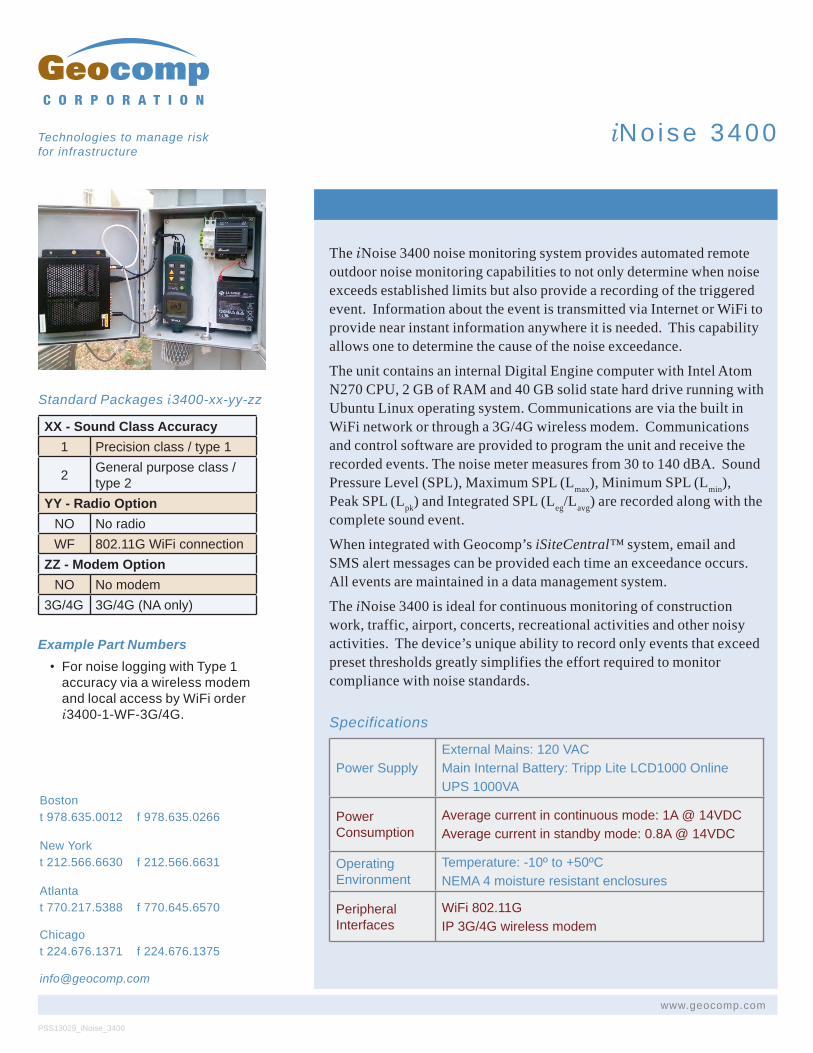
The iNoise 3400 noise monitoring system provides automated remote outdoor noise monitoring capabilities to not only determine when noise exceeds established limits but also provide a recording of the triggered event. Information about the event is transmitted via Internet or WiFi to provide near instant information anywhere it is needed. This capability allows one to determine the cause of the noise exceedance.
The unit contains an internal Digital Engine computer with Intel Atom N270 CPU, 2 GB of RAM and 40 GB solid state hard drive running with Ubuntu Linux operating system. Communications are via the built in WiFi network or through a 3G/4G wireless modem. Communications and control software are provided to program the unit and receive the recorded events. The noise meter measures from 30 to 140 dBA. Sound Pressure Level (SPL), Maximum SPL (Lmax), Minimum SPL (Lmin), Peak SPL (Lpk) and Integrated SPL (Leg/Lavg) are recorded along with the complete sound event.
When integrated with Geocomp’s iSiteCentral™ system, email and SMS alert messages can be provided each time an exceedance occurs. All events are maintained in a data management system.
The iNoise 3400 is ideal for continuous monitoring of construction work, traffic, airport, concerts, recreational activities and other noisy activities. The device’s unique ability to record only events that exceed preset thresholds greatly simplifies the effort required to monitor compliance with noise standards.
Specifications
PSS13029_iNoise_3400
www.geocomp.com
C O R P O R A T I O N
Technologies to manage risk for infrastructure
iNo ise 3400
Bostont 978.635.0012 f 978.635.0266
New Yorkt 212.566.6630 f 212.566.6631
Atlanta t 770.217.5388 f 770.645.6570
Chicago t 224.676.1371 f 224.676.1375
Standard Packages i3400-xx-yy-zz
XX - Sound Class Accuracy1 Precision class / type 1
2 General purpose class / type 2
YY - Radio OptionNO No radioWF 802.11G WiFi connection
ZZ - Modem OptionNO No modem
3G/4G 3G/4G (NA only)
Example Part Numbers• For noise logging with Type 1
accuracy via a wireless modem and local access by WiFi order i3400-1-WF-3G/4G.
Power SupplyExternal Mains: 120 VACMain Internal Battery: Tripp Lite LCD1000 Online UPS 1000VA
Power Consumption
Average current in continuous mode: 1A @ 14VDCAverage current in standby mode: 0.8A @ 14VDC
Operating Environment
Temperature: -10º to +50ºCNEMA 4 moisture resistant enclosures
Peripheral Interfaces
WiFi 802.11GIP 3G/4G wireless modem
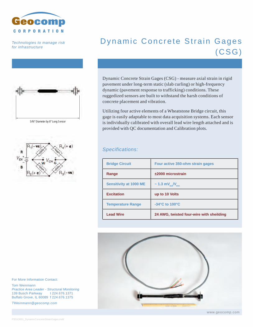
Dynamic Concrete Strain Gages (CSG) - measure axial strain in rigid pavement under long-term static (slab curling) or high-frequency dynamic (pavement response to trafficking) conditions. These ruggedized sensors are built to withstand the harsh conditions of concrete placement and vibration.
Utilizing four active elements of a Wheatstone Bridge circuit, this gage is easily adaptable to most data acquisition systems. Each sensor is individually calibrated with overall lead wire length attached and is provided with QC documentation and Calibration plots.
Specifications:
Bridge Circuit Four active 350-ohm strain gages
Range ±2000 microstrain
Sensitivity at 1000 ME ~ 1.3 mVout/Vexc
Excitation up to 10 Volts
Temperature Range -34°C to 100°C
Lead Wire 24 AWG, twisted four-wire with sheilding
PSS13001_DynamicConcreteStrainGages.indd
www.geocomp.com
C O R P O R A T I O N
Technologies to manage risk for infrastructure
For More Information Contact:
Tom Weinmann Practice Area Leader - Structural Monitoring 139 Busch Parkway t 224.676.1371 Buffalo Grove, IL 60089 f 224.676.1375
Dynamic Conc re te S t ra in Gages (CSG)
5/16" Diameter by 8" Long Sensor
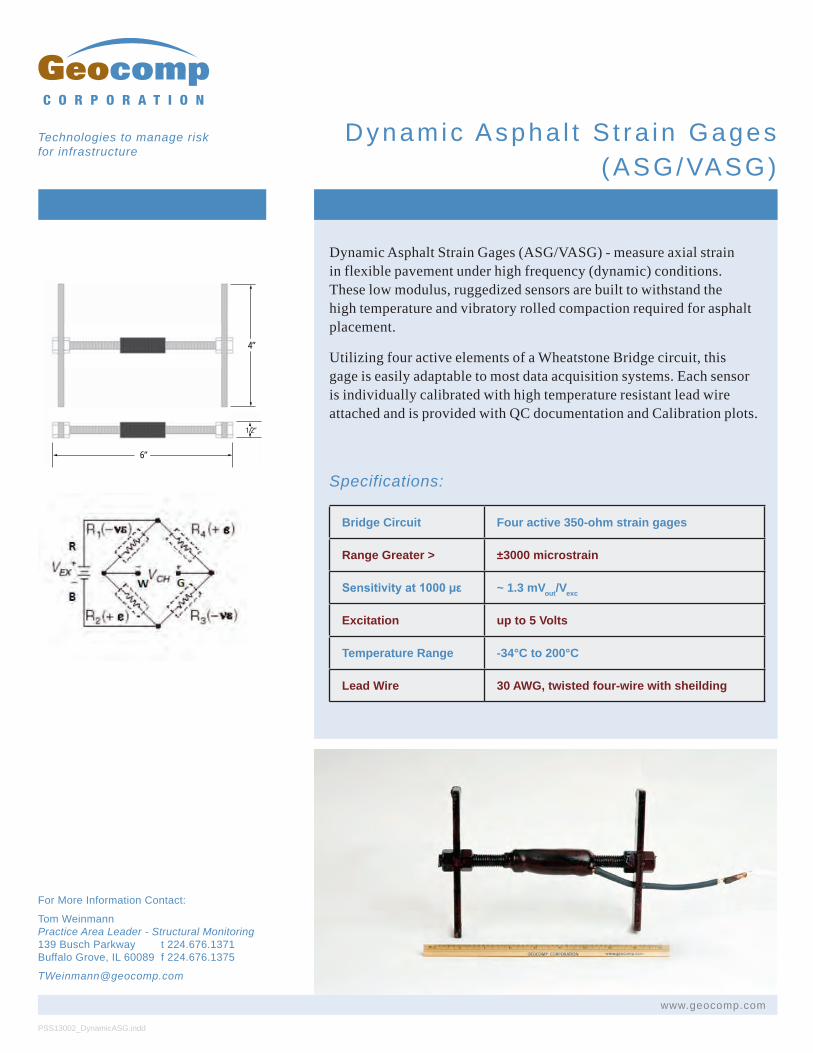
Dynamic Asphalt Strain Gages (ASG/VASG) - measure axial strain in flexible pavement under high frequency (dynamic) conditions. These low modulus, ruggedized sensors are built to withstand the high temperature and vibratory rolled compaction required for asphalt placement.
Utilizing four active elements of a Wheatstone Bridge circuit, this gage is easily adaptable to most data acquisition systems. Each sensor is individually calibrated with high temperature resistant lead wire attached and is provided with QC documentation and Calibration plots.
Specifications:
Bridge Circuit Four active 350-ohm strain gages
Range Greater > ±3000 microstrain
Sensitivity at 1000 µε ~ 1.3 mVout/Vexc
Excitation up to 5 Volts
Temperature Range -34°C to 200°C
Lead Wire 30 AWG, twisted four-wire with sheilding
PSS13002_DynamicASG.indd
www.geocomp.com
C O R P O R A T I O N
Technologies to manage risk for infrastructure
For More Information Contact:
Tom Weinmann Practice Area Leader - Structural Monitoring 139 Busch Parkway t 224.676.1371 Buffalo Grove, IL 60089 f 224.676.1375
Dynamic Aspha l t S t ra in Gages(ASG/VASG)
4”
1/2”
6”
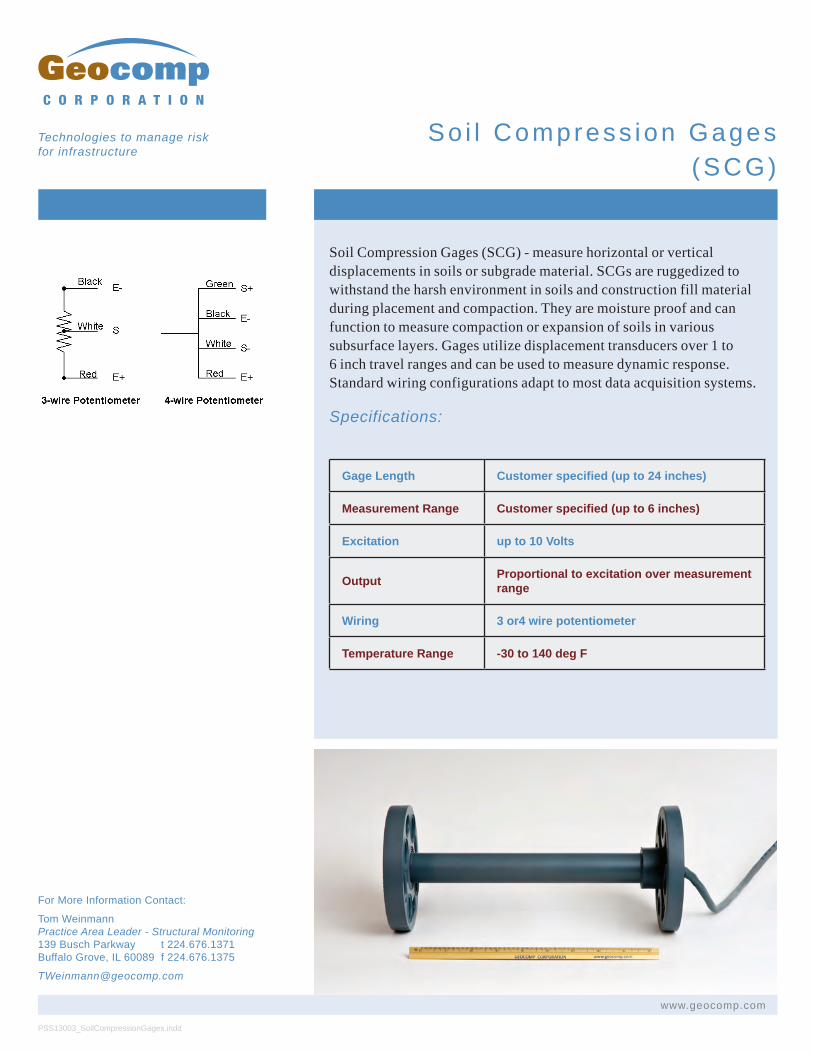
Soil Compression Gages (SCG) - measure horizontal or vertical displacements in soils or subgrade material. SCGs are ruggedized to withstand the harsh environment in soils and construction fill material during placement and compaction. They are moisture proof and can function to measure compaction or expansion of soils in various subsurface layers. Gages utilize displacement transducers over 1 to 6 inch travel ranges and can be used to measure dynamic response. Standard wiring configurations adapt to most data acquisition systems.
Specifications:
Gage Length Customer specified (up to 24 inches)
Measurement Range Customer specified (up to 6 inches)
Excitation up to 10 Volts
Output Proportional to excitation over measurement range
Wiring 3 or4 wire potentiometer
Temperature Range -30 to 140 deg F
PSS13003_SoilCompressionGages.indd
www.geocomp.com
C O R P O R A T I O N
Technologies to manage risk for infrastructure
For More Information Contact:
Tom Weinmann Practice Area Leader - Structural Monitoring 139 Busch Parkway t 224.676.1371 Buffalo Grove, IL 60089 f 224.676.1375
So i l Compress ion Gages (SCG)
33PB008

We design and manufacture automated laboratory testing systems and
remote monitoring devices. We focus on creating products
that help our clients accomplish their goals efficiently and quickly,
whether it be in teaching, research, commercial, or other
applications. We design our automated testing systems to help the user
perform tests efficiently and quickly and produce high-quality
results. Our remote monitoring systems are robust, versatile, and are easy
to use in varying environmental settings. We serve numerous clients in over
50 countries. Join our many satisfied customers and make us your trusted
source for remote monitoring equipment and automated laboratory testing
systems.
Contact us to be added to our orders list.
GEOCOMP PRODUCTS