Embed Size (px)
Citation preview
Geometrical optics
Ing. Jaroslav Jíra, CSc.
Physics 2
Basic Terms
Optics - Branch of Physics, concerning the interaction of light with matter Geometrical Optics - subset of optics concerning interaction of light with macroscopic material (material larger than a human hair – 50μm)
Light can travel through a medium like: empty space, air, glass, water
Light rays traveling in the same medium will travel in a straight line.
Generally, when light strikes the surface of an object, a part of light is reflected. The rest can be either absorbed (and transformed into heat) or it passes through the object if the object is transparent.
At the boundary between two media, the light ray can change direction by:
Reflection or Refraction
incident ray reflected ray
normal to surface
αi αr
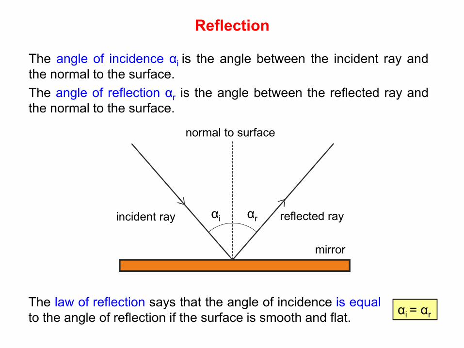
Reflection
mirror
The angle of incidence αi is the angle between the incident ray and the normal to the surface. The angle of reflection αr is the angle between the reflected ray and the normal to the surface.
The law of reflection says that the angle of incidence is equal to the angle of reflection if the surface is smooth and flat. αi = αr
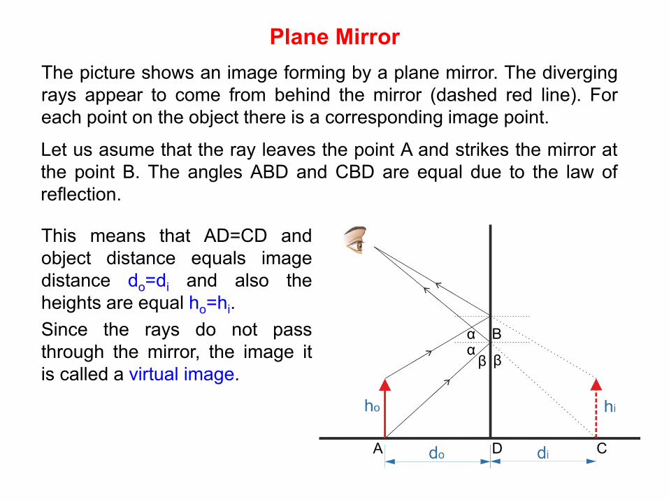
Plane Mirror The picture shows an image forming by a plane mirror. The diverging rays appear to come from behind the mirror (dashed red line). For each point on the object there is a corresponding image point.
α α β β
B
A D C
This means that AD=CD and object distance equals image distance do=di and also the heights are equal ho=hi. Since the rays do not pass through the mirror, the image it is called a virtual image.
Let us asume that the ray leaves the point A and strikes the mirror at the point B. The angles ABD and CBD are equal due to the law of reflection.
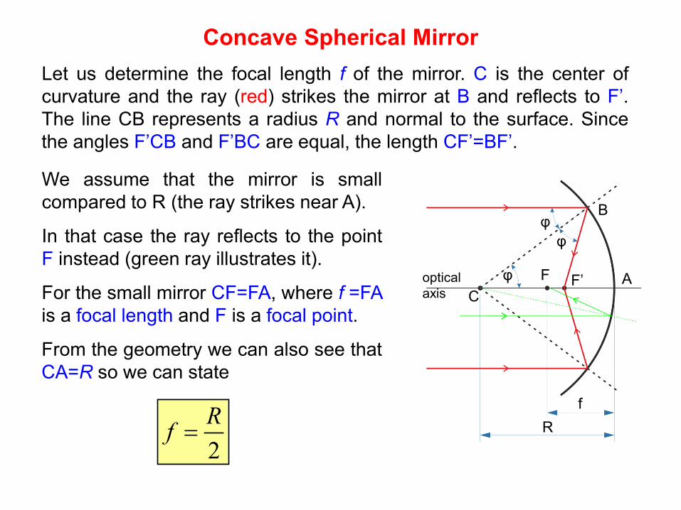
Concave Spherical Mirror Let us determine the focal length f of the mirror. C is the center of curvature and the ray (red) strikes the mirror at B and reflects to F’. The line CB represents a radius R and normal to the surface. Since the angles F’CB and F’BC are equal, the length CF’=BF’.
R
f
C
B
A F F’
φ φ
φ
We assume that the mirror is small compared to R (the ray strikes near A).
In that case the ray reflects to the point F instead (green ray illustrates it).
For the small mirror CF=FA, where f =FA is a focal length and F is a focal point.
From the geometry we can also see that CA=R so we can state
optical axis
2Rf =
Concave Spherical Mirror Image construction
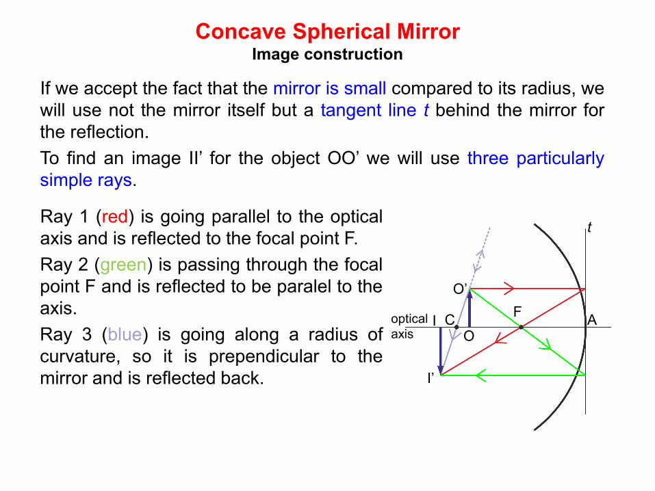
If we accept the fact that the mirror is small compared to its radius, we will use not the mirror itself but a tangent line t behind the mirror for the reflection. To find an image II’ for the object OO’ we will use three particularly simple rays.
A F C
O
O’
I
I’
t Ray 1 (red) is going parallel to the optical axis and is reflected to the focal point F. Ray 2 (green) is passing through the focal point F and is reflected to be paralel to the axis. Ray 3 (blue) is going along a radius of curvature, so it is prependicular to the mirror and is reflected back.
optical axis
Concave Spherical Mirror Mirror equation
do
di
R
γ α β
δ
φ
φ
O C I A
P
s
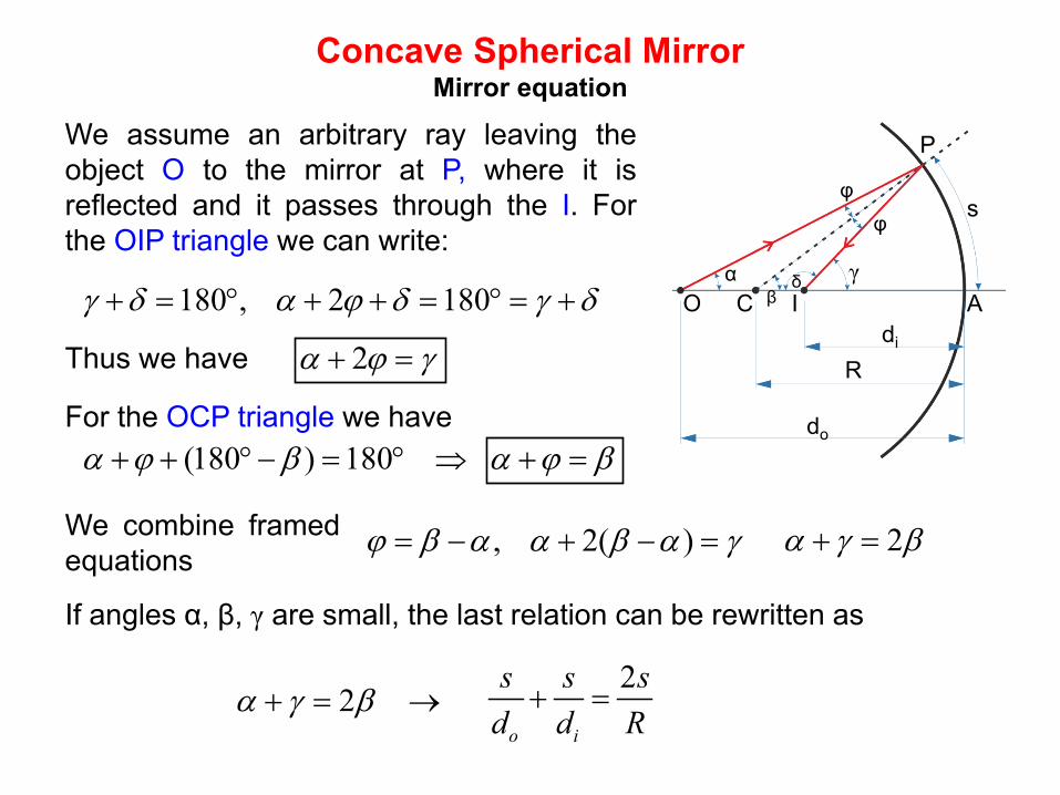
We assume an arbitrary ray leaving the object O to the mirror at P, where it is reflected and it passes through the I. For the OIP triangle we can write:
180 , 2 180γ δ α ϕ δ γ δ+ = ° + + = ° = +
Thus we have 2α ϕ γ+ =
For the OCP triangle we have (180 ) 180α ϕ β+ + °− = ° ⇒
We combine framed equations
, 2( )ϕ β α α β α γ= − + − =
α ϕ β+ =
2α γ β+ =
If angles α, β, γ are small, the last relation can be rewritten as
2
o i
s s sd d R
+ =2α γ β+ = →
Concave Spherical Mirror Mirror equation - continued
do
di
R
γ α β
δ
φ
φ
O C I A
P
s
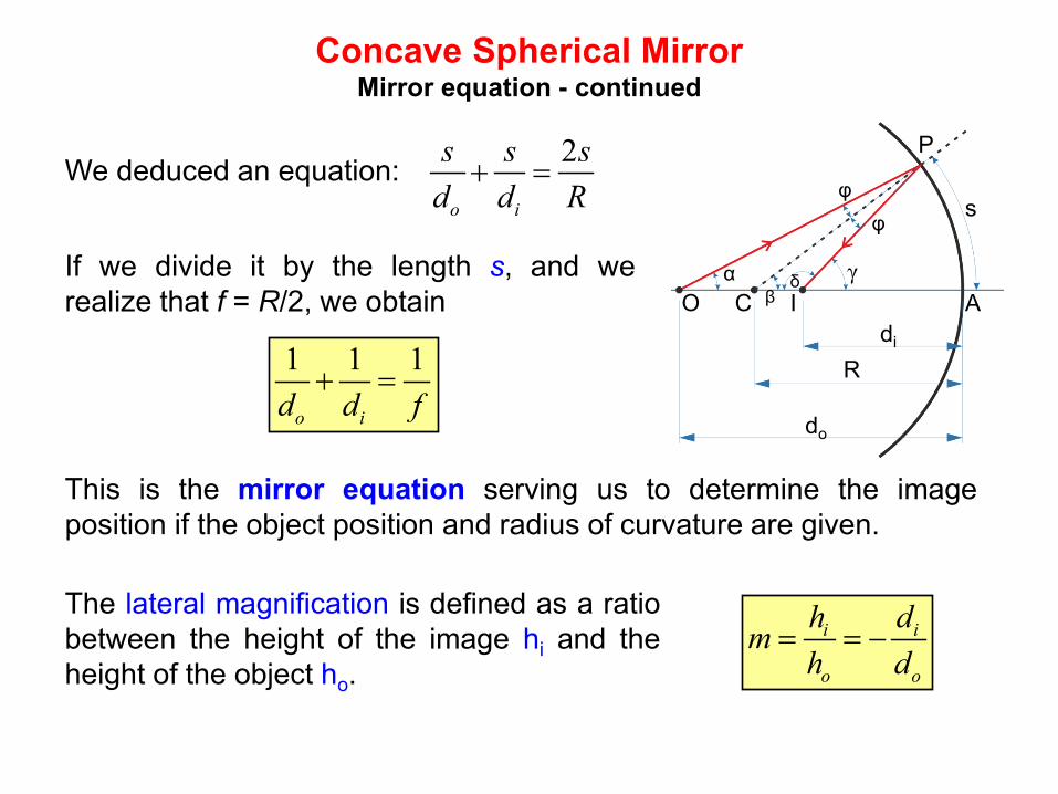
We deduced an equation: 2
o i
s s sd d R
+ =
If we divide it by the length s, and we realize that f = R/2, we obtain
1 1 1
o id d f+ =
This is the mirror equation serving us to determine the image position if the object position and radius of curvature are given.
The lateral magnification is defined as a ratio between the height of the image hi and the height of the object ho.
i i
o o
h dmh d
= = −
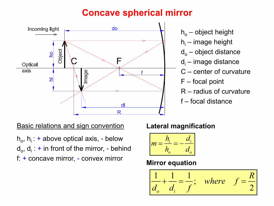
Concave spherical mirror
ho – object height hi – image height do – object distance di – image distance C – center of curvature F – focal point R – radius of curvature f – focal distance
Basic relations and sign convention
ho, hi : + above optical axis, - below do, di : + in front of the mirror, - behind f: + concave mirror, - convex mirror
i i
o o
h dmh d
= = −
Mirror equation
1 1 1 ;2o i
Rwhere fd d f
+ = =
Lateral magnification
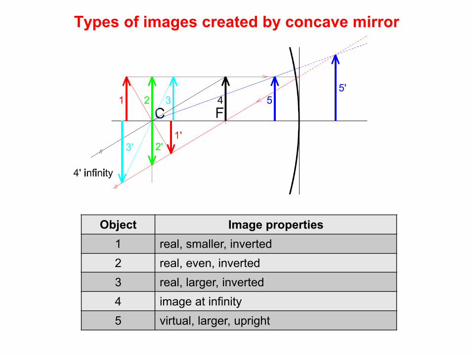
Types of images created by concave mirror
Object Image properties 1 real, smaller, inverted 2 real, even, inverted 3 real, larger, inverted 4 image at infinity 5 virtual, larger, upright
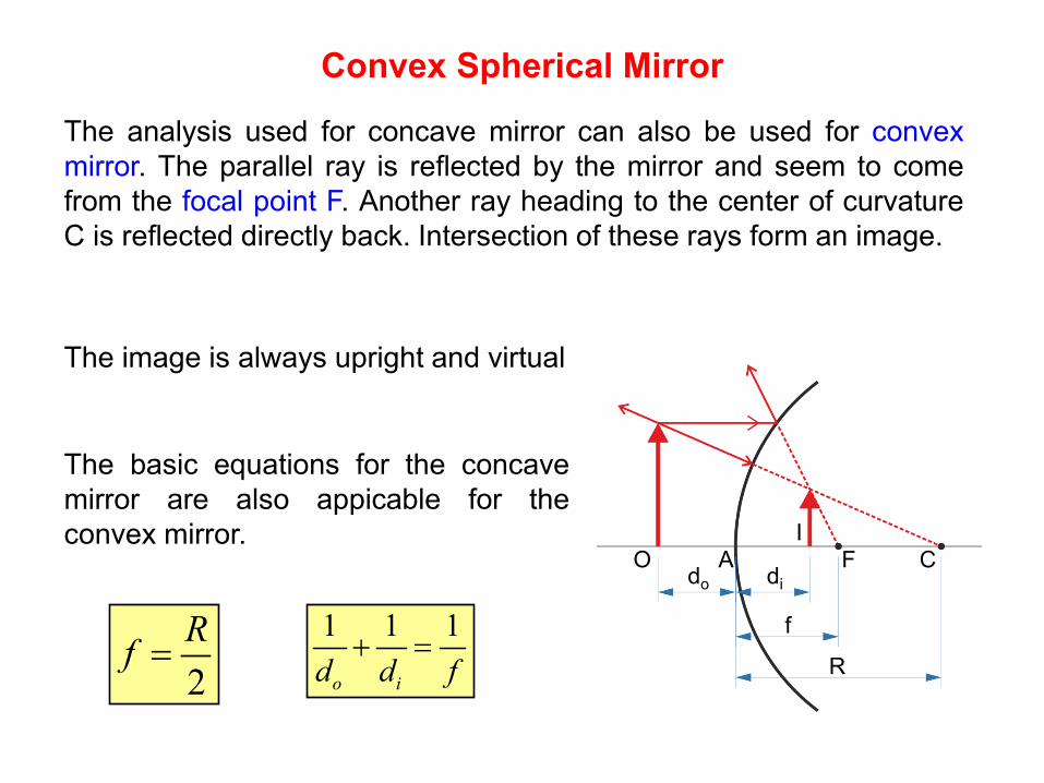
Convex Spherical Mirror
do di
R
O C
I A F
The analysis used for concave mirror can also be used for convex mirror. The parallel ray is reflected by the mirror and seem to come from the focal point F. Another ray heading to the center of curvature C is reflected directly back. Intersection of these rays form an image.
f
2Rf =
1 1 1
o id d f+ =
The basic equations for the concave mirror are also appicable for the convex mirror.
The image is always upright and virtual
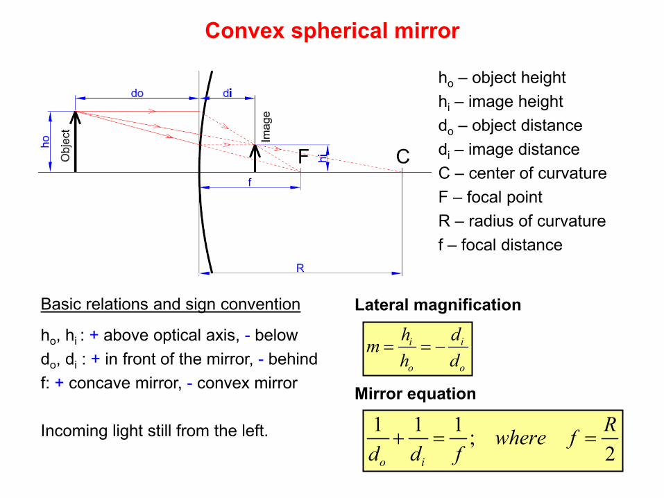
Convex spherical mirror
ho – object height hi – image height do – object distance di – image distance C – center of curvature F – focal point R – radius of curvature f – focal distance
Basic relations and sign convention
ho, hi : + above optical axis, - below do, di : + in front of the mirror, - behind f: + concave mirror, - convex mirror Incoming light still from the left.
i i
o o
h dmh d
= = −
Mirror equation
1 1 1 ;2o i
Rwhere fd d f
+ = =
Lateral magnification
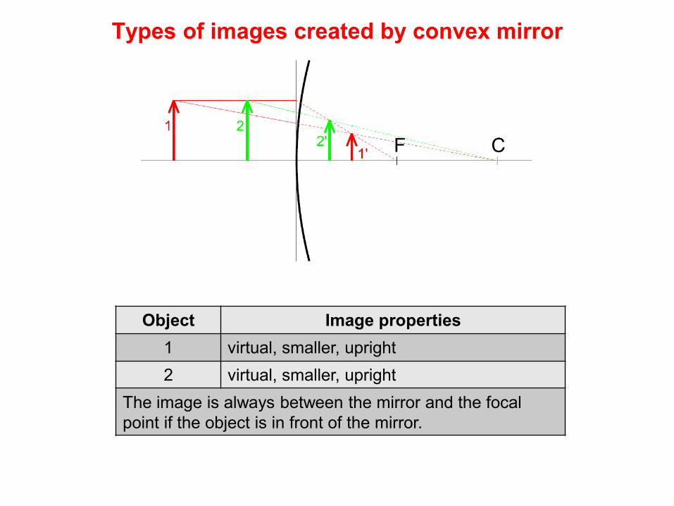
Types of images created by convex mirror
Object Image properties 1 virtual, smaller, upright 2 virtual, smaller, upright
The image is always between the mirror and the focal point if the object is in front of the mirror.
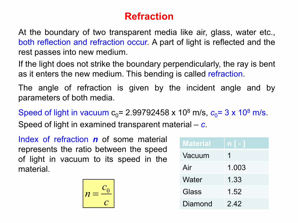
At the boundary of two transparent media like air, glass, water etc., both reflection and refraction occur. A part of light is reflected and the rest passes into new medium. If the light does not strike the boundary perpendicularly, the ray is bent as it enters the new medium. This bending is called refraction.
0cnc
=
Refraction
Index of refraction n of some material represents the ratio between the speed of light in vacuum to its speed in the material.
Material n [ - ] Vacuum 1 Air 1.003 Water 1.33 Glass 1.52 Diamond 2.42
The angle of refraction is given by the incident angle and by parameters of both media.
Speed of light in vacuum c0= 2.99792458 x 10⁸ m/s, c0= 3 x 10⁸ m/s. Speed of light in examined transparent material – c.
Refraction normal to surface
incident ray reflected ray
refracted ray
α α
β
medium n1
medium n2
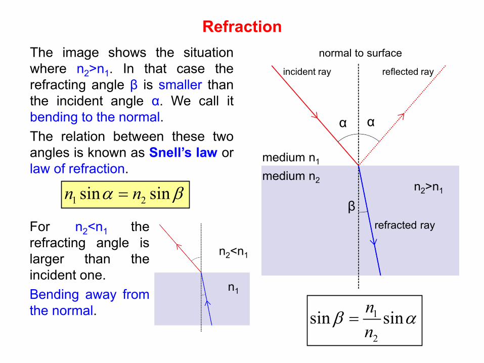
The image shows the situation where n2>n1. In that case the refracting angle β is smaller than the incident angle α. We call it bending to the normal. The relation between these two angles is known as Snell’s law or law of refraction.
1 2sin sinn nα β=
For n2<n1 the refracting angle is larger than the incident one. Bending away from the normal.
n1
n2<n1
1
2
sin sinnn
β α=
n2>n1
Critical Angle and Total Reflection
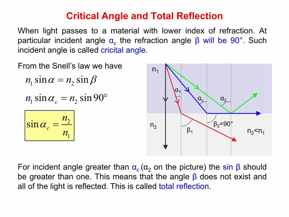
From the Snell’s law we have
1 2sin sinn nα β=
1 2sin sin 90cn nα = °
2
1
sin cnn
α =n2<n1
n1
n2
α1 αc α2
For incident angle greater than αc (α2 on the picture) the sin β should be greater than one. This means that the angle β does not exist and all of the light is reflected. This is called total reflection.
β1
β2=90°
When light passes to a material with lower index of refraction. At particular incident angle αc the refraction angle β will be 90°. Such incident angle is called cricital angle.
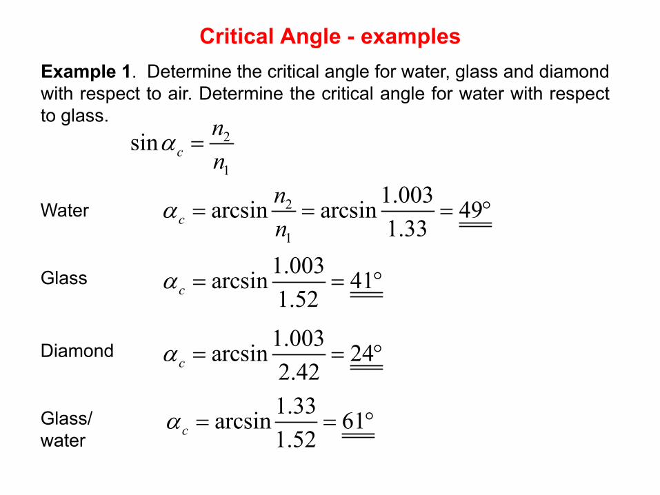
Critical Angle - examples Example 1. Determine the critical angle for water, glass and diamond with respect to air. Determine the critical angle for water with respect to glass.
2
1
1.003arcsin arcsin 491.33c
nn
α = = = °
2
1
sin cnn
α =
Water
1.003arcsin 411.52cα = = °Glass
1.003arcsin 242.42cα = = °Diamond
1.33arcsin 611.52cα = = °Glass/
water
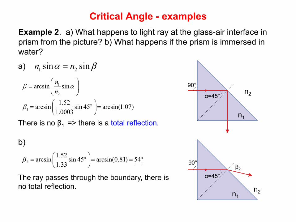
Critical Angle - examples Example 2. a) What happens to light ray at the glass-air interface in prism from the picture? b) What happens if the prism is immersed in water?
1 2sin sinn nα β=
1
2
1
arcsin sin
1.52arcsin sin 45 arcsin(1.07)1.0003
nn
β α
β
=
= ° =
21.52arcsin sin 45 arcsin(0.81) 541.33
β = ° = = ° β2
α=45°
90°
90°
α=45°
a)
b)
There is no β1 => there is a total reflection.
The ray passes through the boundary, there is no total reflection.
n2
n1
n2 n1
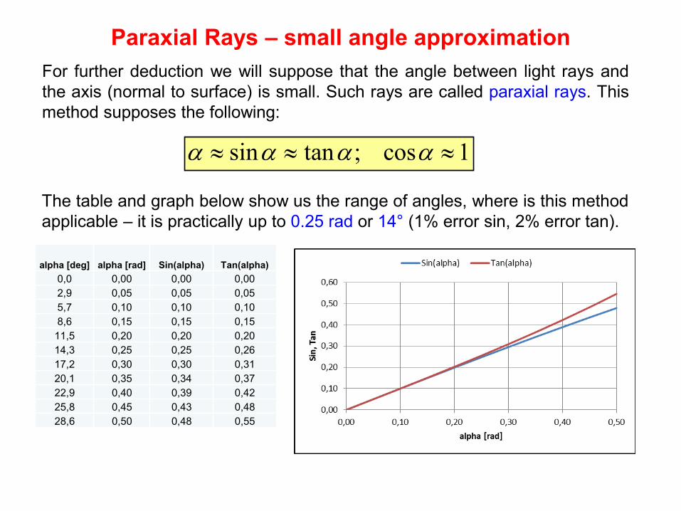
Paraxial Rays – small angle approximation For further deduction we will suppose that the angle between light rays and the axis (normal to surface) is small. Such rays are called paraxial rays. This method supposes the following:
sin tan ; cos 1α α α α≈ ≈ ≈
The table and graph below show us the range of angles, where is this method applicable – it is practically up to 0.25 rad or 14° (1% error sin, 2% error tan).
alpha [deg] alpha [rad] Sin(alpha) Tan(alpha) 0,0 0,00 0,00 0,00 2,9 0,05 0,05 0,05 5,7 0,10 0,10 0,10 8,6 0,15 0,15 0,15
11,5 0,20 0,20 0,20 14,3 0,25 0,25 0,26 17,2 0,30 0,30 0,31 20,1 0,35 0,34 0,37 22,9 0,40 0,39 0,42 25,8 0,45 0,43 0,48 28,6 0,50 0,48 0,55
Refraction at Spherical Surface
n1 n2
h
di
R
do
α β γ δ
φ1 φ2
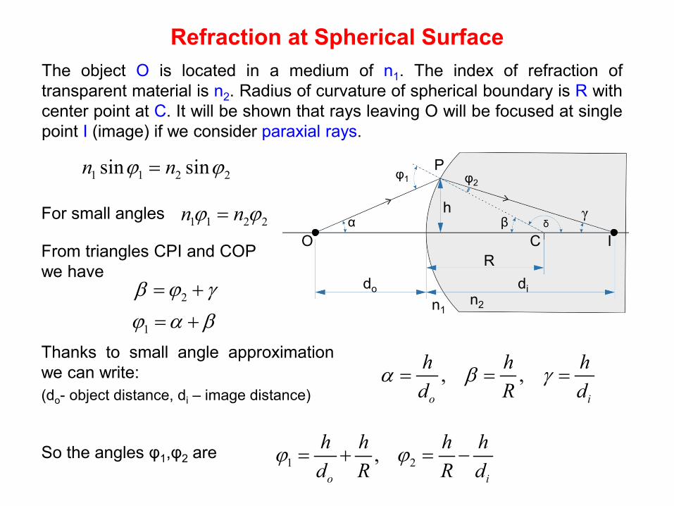
The object O is located in a medium of n1. The index of refraction of transparent material is n2. Radius of curvature of spherical boundary is R with center point at C. It will be shown that rays leaving O will be focused at single point I (image) if we consider paraxial rays.
O I C
P 1 1 2 2sin sinn nϕ ϕ=
For small angles 1 1 2 2n nϕ ϕ=
From triangles CPI and COP we have
2β ϕ γ= +
1ϕ α β= +
, ,o i
h h hd R d
α β γ= = =Thanks to small angle approximation we can write: (do- object distance, di – image distance)
So the angles φ1,φ2 are 1 2,
o i
h h h hd R R d
ϕ ϕ= + = −
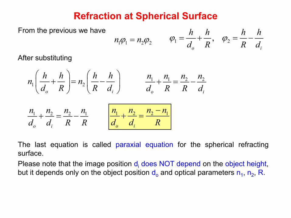
Refraction at Spherical Surface From the previous we have
1 1 2 2n nϕ ϕ= 1 2,o i
h h h hd R R d
ϕ ϕ= + = −
After substituting
1 2o i
h h h hn nd R R d
+ = −
1 1 2 2
o i
n n n nd R R d
+ = −
1 2 2 1
o i
n n n nd d R R
+ = − 1 2 2 1
o i
n n n nd d R
−+ =
The last equation is called paraxial equation for the spherical refracting surface. Please note that the image position di does NOT depend on the object height, but it depends only on the object position do and optical parameters n1, n2, R.
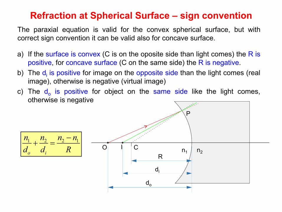
Refraction at Spherical Surface – sign convention The paraxial equation is valid for the convex spherical surface, but with correct sign convention it can be valid also for concave surface.
do
R
di
P
a) If the surface is convex (C is on the oposite side than light comes) the R is positive, for concave surface (C on the same side) the R is negative.
b) The di is positive for image on the opposite side than the light comes (real image), otherwise is negative (virtual image)
c) The do is positive for object on the same side like the light comes, otherwise is negative
O C I n1 n2
1 2 2 1
o i
n n n nd d R
−+ =
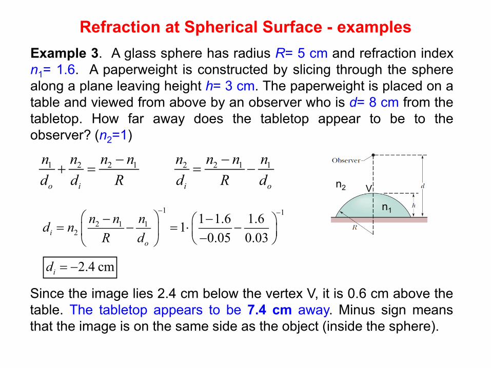
Refraction at Spherical Surface - examples Example 3. A glass sphere has radius R= 5 cm and refraction index n1= 1.6. A paperweight is constructed by slicing through the sphere along a plane leaving height h= 3 cm. The paperweight is placed on a table and viewed from above by an observer who is d= 8 cm from the tabletop. How far away does the tabletop appear to be to the observer? (n2=1)
1 2 2 1
o i
n n n nd d R
−+ = 2 2 1 1
i o
n n n nd R d
−= −
1 12 1 1
21 1.6 1.61
0.05 0.03io
n n nd nR d
− − − − = − = ⋅ − −
2.4 cmid = −
V
Since the image lies 2.4 cm below the vertex V, it is 0.6 cm above the table. The tabletop appears to be 7.4 cm away. Minus sign means that the image is on the same side as the object (inside the sphere).
n1
n2
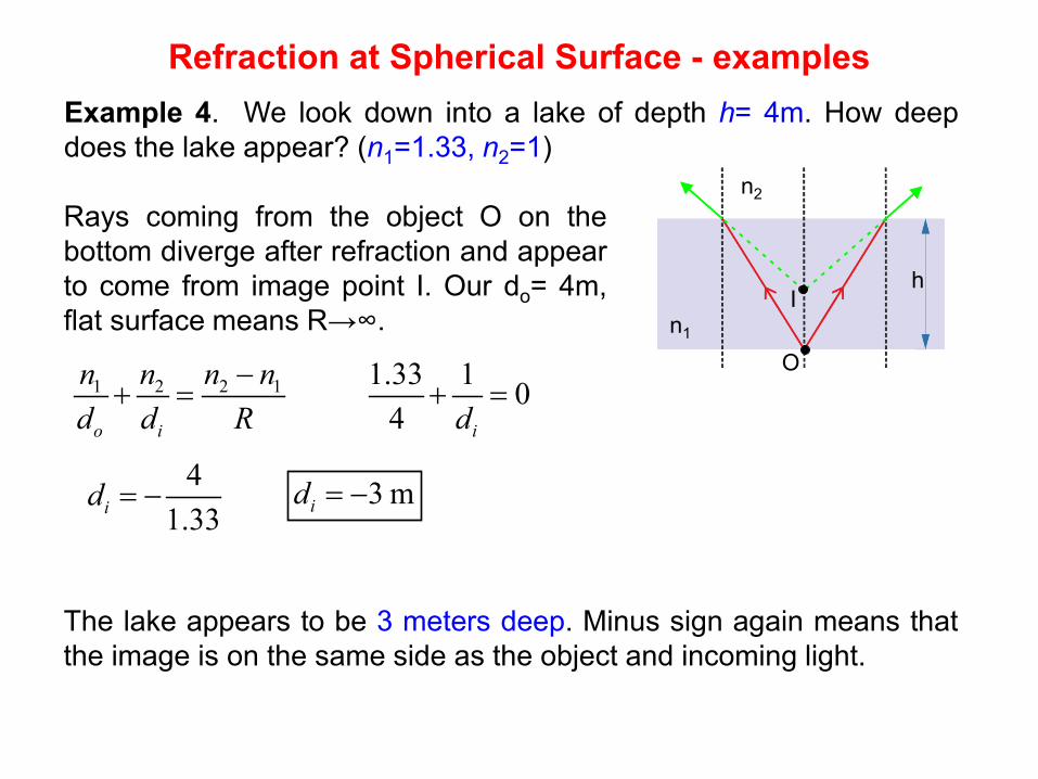
Refraction at Spherical Surface - examples Example 4. We look down into a lake of depth h= 4m. How deep does the lake appear? (n1=1.33, n2=1)
1 2 2 1
o i
n n n nd d R
−+ =
h
The lake appears to be 3 meters deep. Minus sign again means that the image is on the same side as the object and incoming light.
n1
n2
O
I
Rays coming from the object O on the bottom diverge after refraction and appear to come from image point I. Our do= 4m, flat surface means R→∞.
1.33 1 04 id
+ =
41.33id = − 3 mid = −
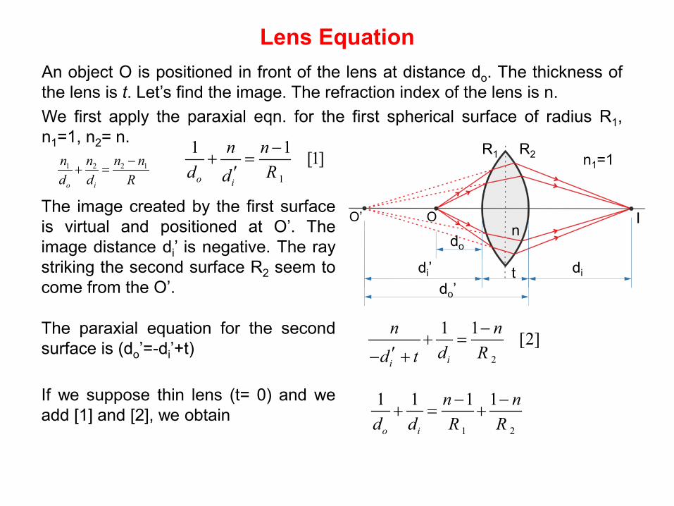
Lens Equation An object O is positioned in front of the lens at distance do. The thickness of the lens is t. Let’s find the image. The refraction index of the lens is n. We first apply the paraxial eqn. for the first spherical surface of radius R1, n1=1, n2= n.
1
1 1 [1]o i
n nd Rd
−+ =
′n1=1
n
The image created by the first surface is virtual and positioned at O’. The image distance di’ is negative. The ray striking the second surface R2 seem to come from the O’.
I O O’
The paraxial equation for the second surface is (do’=-di’+t)
2
1 1 [2]ii
n nd Rd t
−+ =
′− +
1 2 2 1
o i
n n n nd d R
−+ =
If we suppose thin lens (t= 0) and we add [1] and [2], we obtain
1 2
1 1 1 1
o i
n nd d R R
− −+ = +
do
di di’ t do’
R1 R2
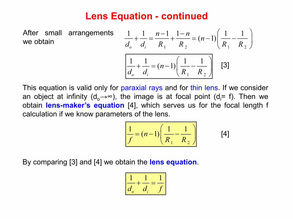
Lens Equation - continued
This equation is valid only for paraxial rays and for thin lens. If we consider an object at infinity (do→∞), the image is at focal point (di= f). Then we obtain lens-maker’s equation [4], which serves us for the focal length f calculation if we know parameters of the lens.
[3]
After small arrangements we obtain
1 2 1 2
1 1 1 1 1 1( 1)o i
n n nd d R R R R
− −+ = + = − −
1 2
1 1 1 1( 1)o i
nd d R R
+ = − −
1 2
1 1 1( 1)nf R R
= − −
[4]
By comparing [3] and [4] we obtain the lens equation.
1 1 1
o id d f+ =
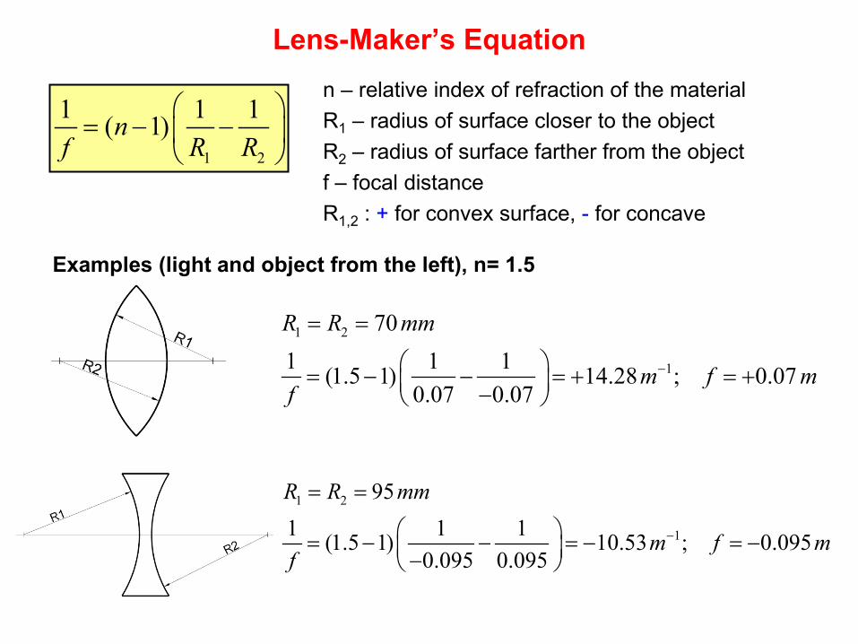
Lens-Maker’s Equation
1 2
1 1 1( 1)nf R R
= − −
n – relative index of refraction of the material R1 – radius of surface closer to the object R2 – radius of surface farther from the object f – focal distance R1,2 : + for convex surface, - for concave
Examples (light and object from the left), n= 1.5
1 2
1
701 1 1(1.5 1) 14.28 ; 0.07
0.07 0.07
R R mm
m f mf
−
= =
= − − = + = + −
1 2
1
951 1 1(1.5 1) 10.53 ; 0.095
0.095 0.095
R R mm
m f mf
−
= =
= − − = − = − −
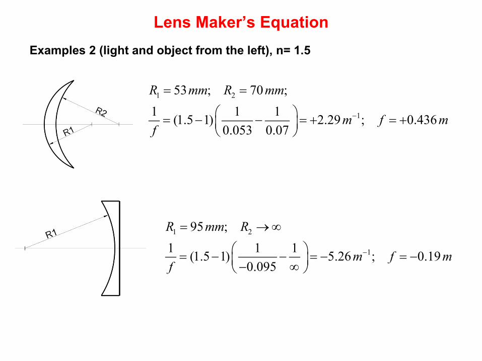
Lens Maker’s Equation Examples 2 (light and object from the left), n= 1.5
1 2
1
53 ; 70 ;1 1 1(1.5 1) 2.29 ; 0.436
0.053 0.07
R mm R mm
m f mf
−
= =
= − − = + = +
1 2
1
95 ;1 1 1(1.5 1) 5.26 ; 0.19
0.095
R mm R
m f mf
−
= →∞
= − − = − = − − ∞
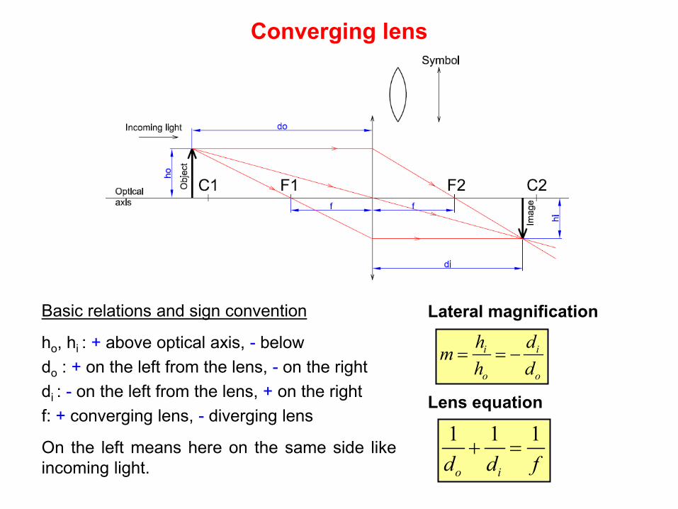
Converging lens
Basic relations and sign convention
ho, hi : + above optical axis, - below do : + on the left from the lens, - on the right di : - on the left from the lens, + on the right f: + converging lens, - diverging lens
On the left means here on the same side like incoming light.
i i
o o
h dmh d
= = −
Lens equation
1 1 1
o id d f+ =
Lateral magnification
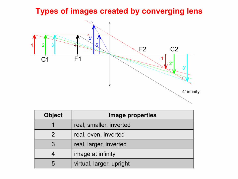
Types of images created by converging lens
Object Image properties 1 real, smaller, inverted 2 real, even, inverted 3 real, larger, inverted 4 image at infinity 5 virtual, larger, upright
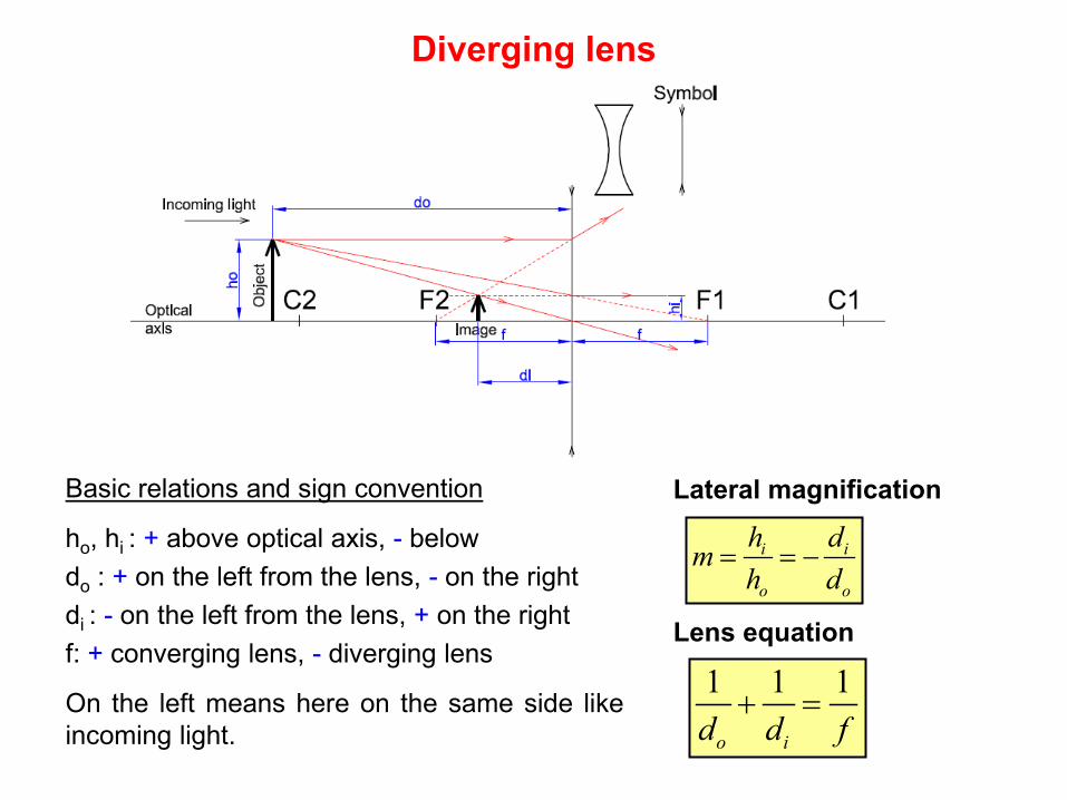
Diverging lens
Basic relations and sign convention
ho, hi : + above optical axis, - below do : + on the left from the lens, - on the right di : - on the left from the lens, + on the right f: + converging lens, - diverging lens
On the left means here on the same side like incoming light.
i i
o o
h dmh d
= = −
Lens equation
1 1 1
o id d f+ =
Lateral magnification
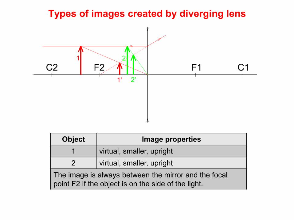
Types of images created by diverging lens
Object Image properties 1 virtual, smaller, upright 2 virtual, smaller, upright
The image is always between the mirror and the focal point F2 if the object is on the side of the light.
A program for the lens simulation
http://physics.bu.edu/~duffy/HTML5/Lenses.html
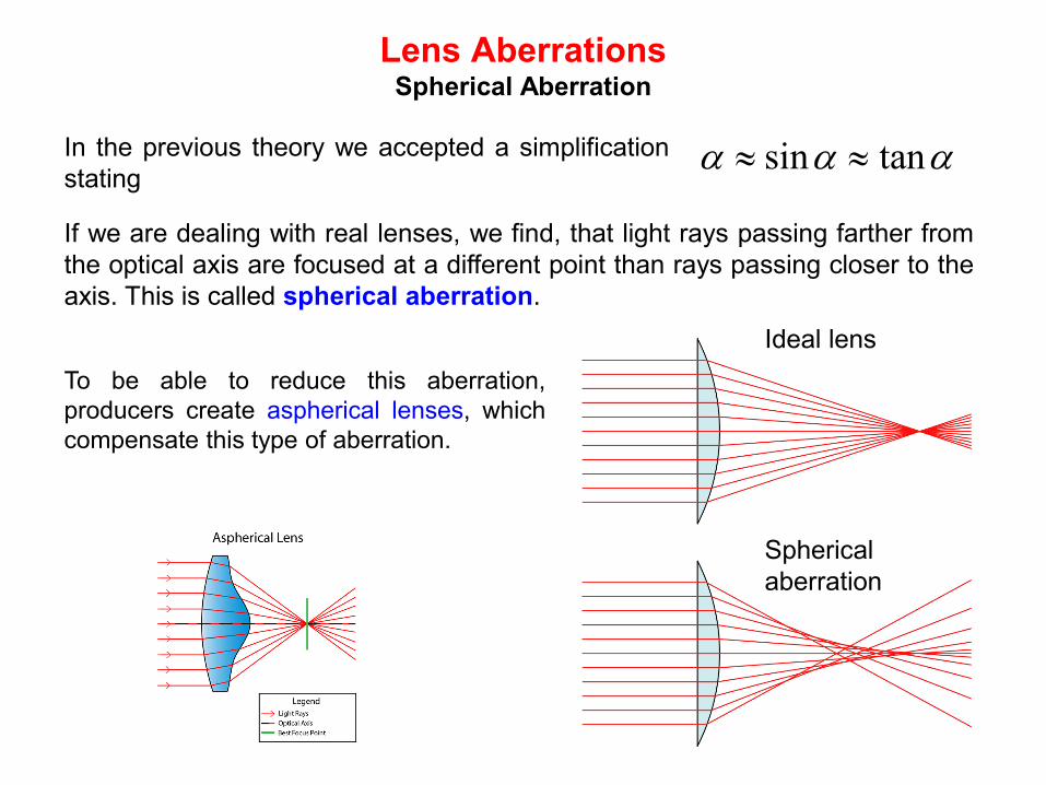
Lens Aberrations Spherical Aberration
In the previous theory we accepted a simplification stating
sin tanα α α≈ ≈
If we are dealing with real lenses, we find, that light rays passing farther from the optical axis are focused at a different point than rays passing closer to the axis. This is called spherical aberration.
Ideal lens
Spherical aberration
To be able to reduce this aberration, producers create aspherical lenses, which compensate this type of aberration.
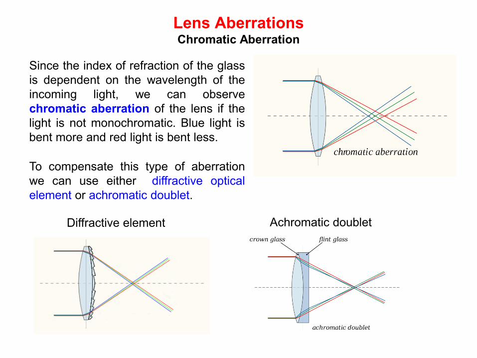
Lens Aberrations Chromatic Aberration
Since the index of refraction of the glass is dependent on the wavelength of the incoming light, we can observe chromatic aberration of the lens if the light is not monochromatic. Blue light is bent more and red light is bent less.
To compensate this type of aberration we can use either diffractive optical element or achromatic doublet.
Diffractive element Achromatic doublet
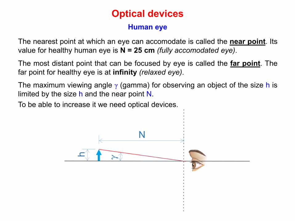
Optical devices Human eye
The nearest point at which an eye can accomodate is called the near point. Its value for healthy human eye is N = 25 cm (fully accomodated eye).
The most distant point that can be focused by eye is called the far point. The far point for healthy eye is at infinity (relaxed eye).
The maximum viewing angle γ (gamma) for observing an object of the size h is limited by the size h and the near point N. To be able to increase it we need optical devices.
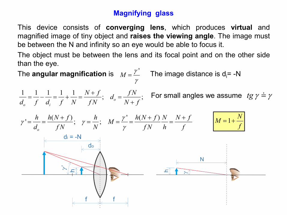
Magnifying glass
This device consists of converging lens, which produces virtual and magnified image of tiny object and raises the viewing angle. The image must be between the N and infinity so an eye would be able to focus it. The object must be between the lens and its focal point and on the other side than the eye. The angular magnification is The image distance is di= -N 'M γ
γ=
1 1 1 1 1 ; ;oo i
N f f Ndd f d f N f N N f
+= − = + = =
+For small angles we assume tg γ γ
( ) ' ( )' ; ;o
h h N f h h N f N N fMd f N N f N h f
γγ γγ
+ + += = = = = = 1 NM
f= +
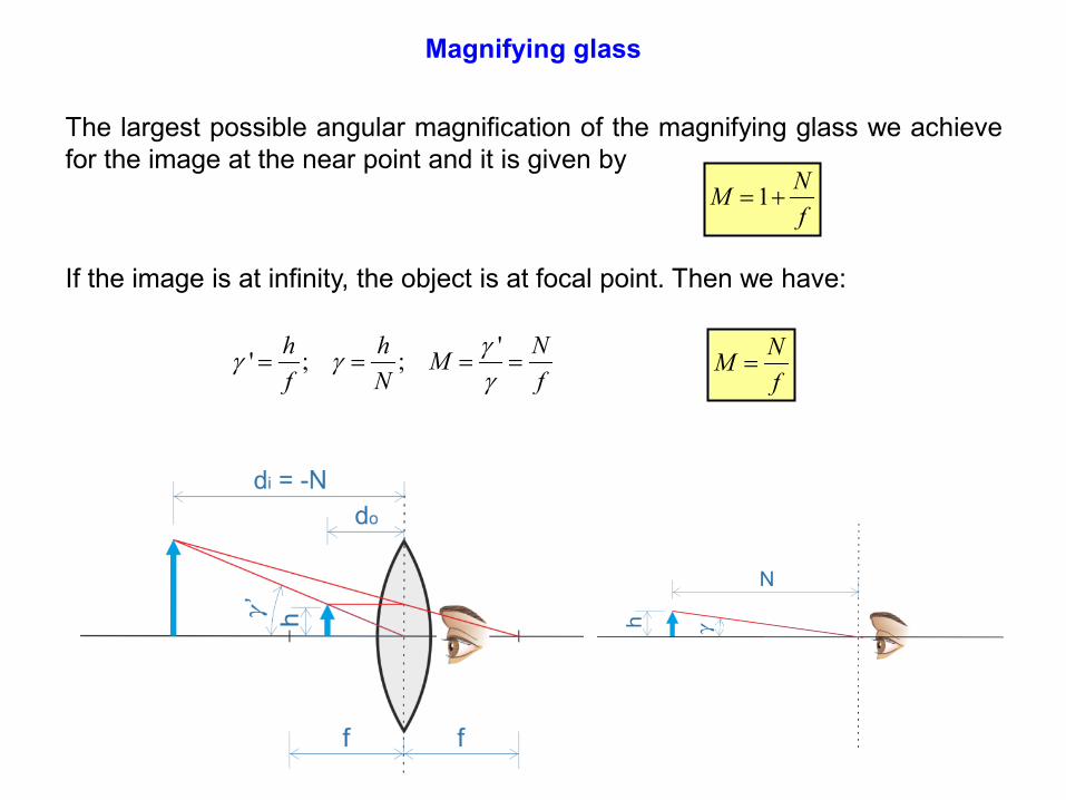
Magnifying glass
The largest possible angular magnification of the magnifying glass we achieve for the image at the near point and it is given by
1 NMf
= +
If the image is at infinity, the object is at focal point. Then we have:
'' ; ;h h NMf N f
γγ γγ
= = = = NMf
=
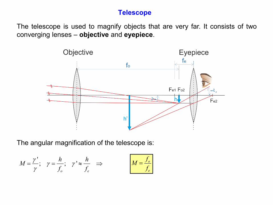
Telescope
The angular magnification of the telescope is:
' ; ; 'o e
h hMf f
γ γ γγ
= = ≈ ⇒
The telescope is used to magnify objects that are very far. It consists of two converging lenses – objective and eyepiece.
o
e
fMf
=
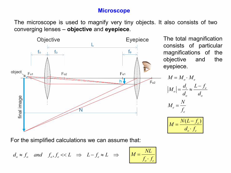
Microscope
The microscope is used to magnify very tiny objects. It also consists of two converging lenses – objective and eyepiece.
The total magnification consists of particular magnifications of the objective and the eyepiece.
o e
i eo
o o
ee
M M Md L fMd d
NMf
= ⋅−
= ≈
=
( )e
o e
N L fMd f
−=
⋅
For the simplified calculations we can assume that:
,o o o e ed f and f f L L f L≈ << ⇒ − ≈ ⇒o e
NLMf f
=⋅
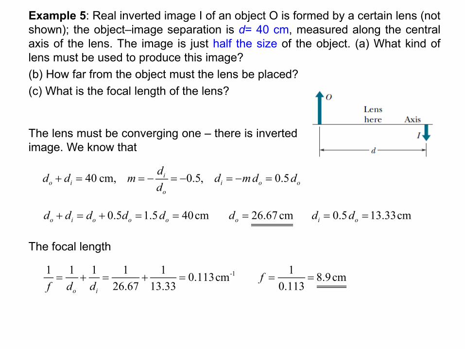
Example 5: Real inverted image I of an object O is formed by a certain lens (not shown); the object–image separation is d= 40 cm, measured along the central axis of the lens. The image is just half the size of the object. (a) What kind of lens must be used to produce this image? (b) How far from the object must the lens be placed? (c) What is the focal length of the lens?
The lens must be converging one – there is inverted image. We know that
40 cm, 0.5, 0.5io i i o o
o
dd d m d m d dd
+ = = − = − = − =
0.5 1.5 40cmo i o o od d d d d+ = + = = 26.67cmod = 0.5 13.33cmi od d= =
The focal length
-11 1 1 1 1 0.113cm26.67 13.33o if d d
= + = + =1 8.9cm
0.113f = =
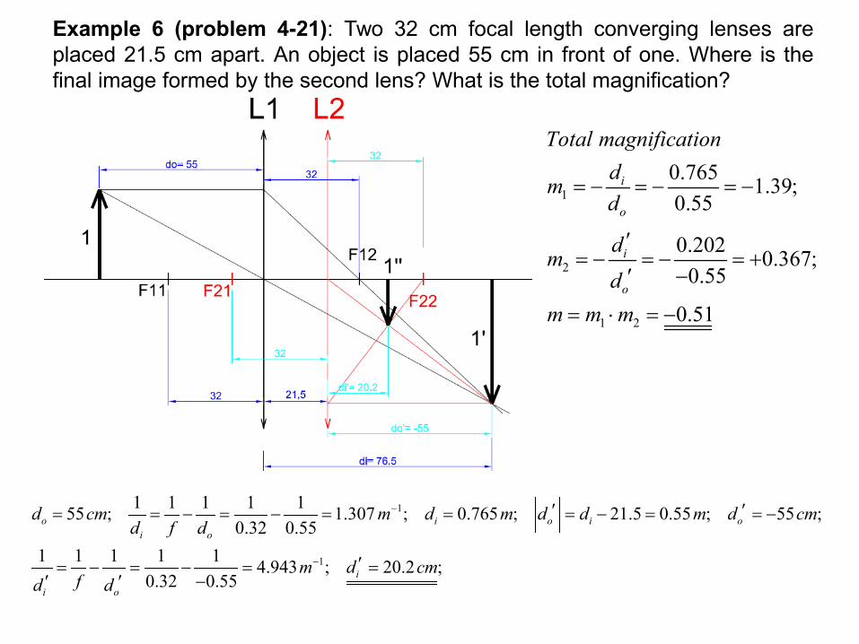
Example 6 (problem 4-21): Two 32 cm focal length converging lenses are placed 21.5 cm apart. An object is placed 55 cm in front of one. Where is the final image formed by the second lens? What is the total magnification?
1
1
1 1 1 1 155 ; 1.307 ; 0.765 ; 21.5 0.55 ; 55 ;0.32 0.55
1 1 1 1 1 4.943 ; 20.2 ;0.32 0.55
o i o i oi o
i
i o
d cm m d m d d m d cmd f d
m d cmfd d
−
−
′ ′= = − = − = = = − = = −
′= − = − = =−′ ′
1
2
1 2
0.765 1.39;0.55
0.202 0.367;0.55
0.51
i
o
i
o
Total magnificationdmd
dmd
m m m
= − = − = −
′= − = − = +
−′
= ⋅ = −