Embed Size (px)
Citation preview
Autodesk Design Academy 2009 Geometry Using Autodesk Inventor
Geometry Using Autodesk Inventor
About This Unit
In every field of engineering, the concepts in geometry are applied at every level. Students learning and visualizing these concepts using Autodesk Inventor will master them and make direct connections to these applications in engineering. The design process uses symmetry, rotations and many other concepts in many facets. Autodesk Inventor can be used as a powerful tool to teach, reinforce and see the importance of geometry.
In this unit, the focus is on two-dimensional geometry with some applications in three dimensions. Instead of using a textbook and working problems, the student will create IPT and IAM files using these concepts. The definitions, structures and geometric relationships will become engaging and challenging exercises for every student. By using Inventor, the connections between geometry and engineering will become apparent and vital.
Lessons
• 3D Solids of Rotation
• Congruent Triangles
• Trigonometric Functions
• Special Quadrilaterals
• Tessellations, Rotations, and Symmetry
• Medians, Altitudes, and Bisectors
© 2008 Autodesk, Inc. 1
Autodesk Design Academy 2009 Geometry Using Autodesk Inventor
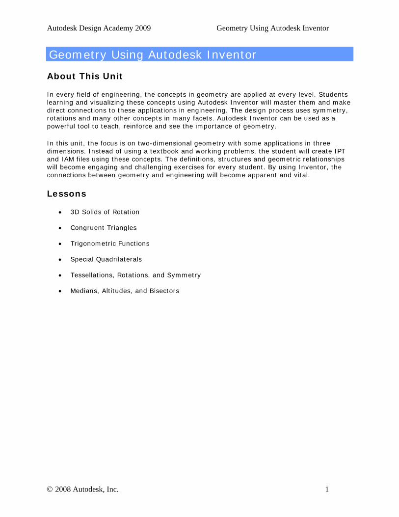
Lesson 1 - 3D Solids of Rotation
About This Lesson
After completing this lesson, you will be able to:
• Calculate the surface area of geometric shapes. • Calculate the volume of geometric shapes. • Demonstrate the application of area and volume formula.
This lesson focuses on creating three-dimensional solids by revolving a two-dimensional figure around an axis.
The students use the Measure command to determine surface area and iProperties to determine volume.
Exercises
• Construct a Cone by Rotation
• Determine the Surface Area of a Cone
• Determine the Volume of a Cone
© 2008 Autodesk, Inc. 2
Autodesk Design Academy 2009 Geometry Using Autodesk Inventor
Standards
Autodesk Design Academy meets content standards for Science, Technology, Engineering, Math (STEM), and Language Arts. To review the list of standards for each lesson, see the National Academic Standards Cross References document in the Printable Lessons folder.
This lesson relates to engineering and math standards.
Key Terms
axis hypotenuse surface area
circumference lateral area vertex
diameter pi volume
height slant height
Lesson Plan
1. Review 3D solids of rotation. (Demonstration) 2. Complete Exercise 1: Construct a Cone by Rotation (Students) 3. Complete Exercise 2: Determine Surface Area of a Cone (Students) 4. Complete Exercise 3: Determine the Volume of a Cone (Students) 5. Evaluate Students. (Evaluation)
© 2008 Autodesk, Inc. 3
Autodesk Design Academy 2009 Geometry Using Autodesk Inventor
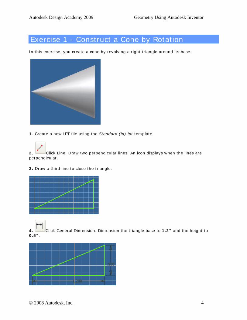
Exercise 1 - Construct a Cone by Rotation
In this exercise, you create a cone by revolving a right triangle around its base.
1. Create a new IPT file using the Standard (in).ipt template.
2. Click Line. Draw two perpendicular lines. An icon displays when the lines are perpendicular.
3. Draw a third line to close the triangle.
4. Click General Dimension. Dimension the triangle base to 1.2" and the height to 0.5".
© 2008 Autodesk, Inc. 4
Autodesk Design Academy 2009 Geometry Using Autodesk Inventor
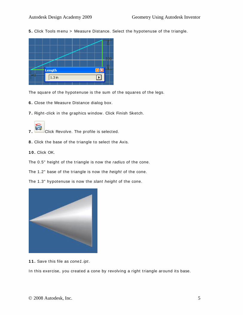
5. Click Tools menu > Measure Distance. Select the hypotenuse of the triangle.
The square of the hypotenuse is the sum of the squares of the legs.
6. Close the Measure Distance dialog box.
7. Right-click in the graphics window. Click Finish Sketch.
7. Click Revolve. The profile is selected.
8. Click the base of the triangle to select the Axis.
10. Click OK. The 0.5" height of the triangle is now the radius of the cone. The 1.2" base of the triangle is now the height of the cone. The 1.3" hypotenuse is now the slant height of the cone.
11. Save this file as cone1.ipt. In this exercise, you created a cone by revolving a right triangle around its base.
© 2008 Autodesk, Inc. 5
Autodesk Design Academy 2009 Geometry Using Autodesk Inventor
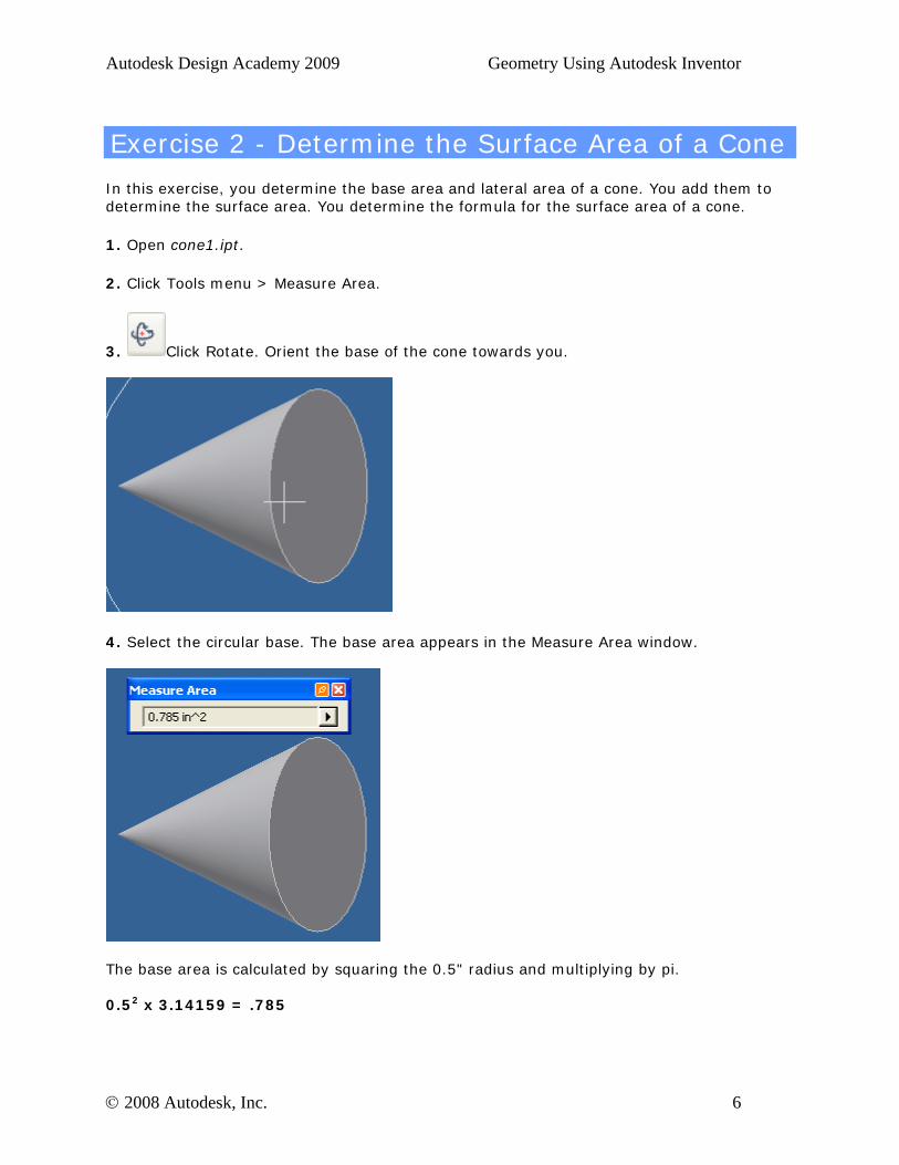
Exercise 2 - Determine the Surface Area of a Cone
In this exercise, you determine the base area and lateral area of a cone. You add them to determine the surface area. You determine the formula for the surface area of a cone.
1. Open cone1.ipt.
2. Click Tools menu > Measure Area.
3. Click Rotate. Orient the base of the cone towards you.
4. Select the circular base. The base area appears in the Measure Area window.
The base area is calculated by squaring the 0.5" radius and multiplying by pi. 0.52 x 3.14159 = .785
© 2008 Autodesk, Inc. 6
Autodesk Design Academy 2009 Geometry Using Autodesk Inventor
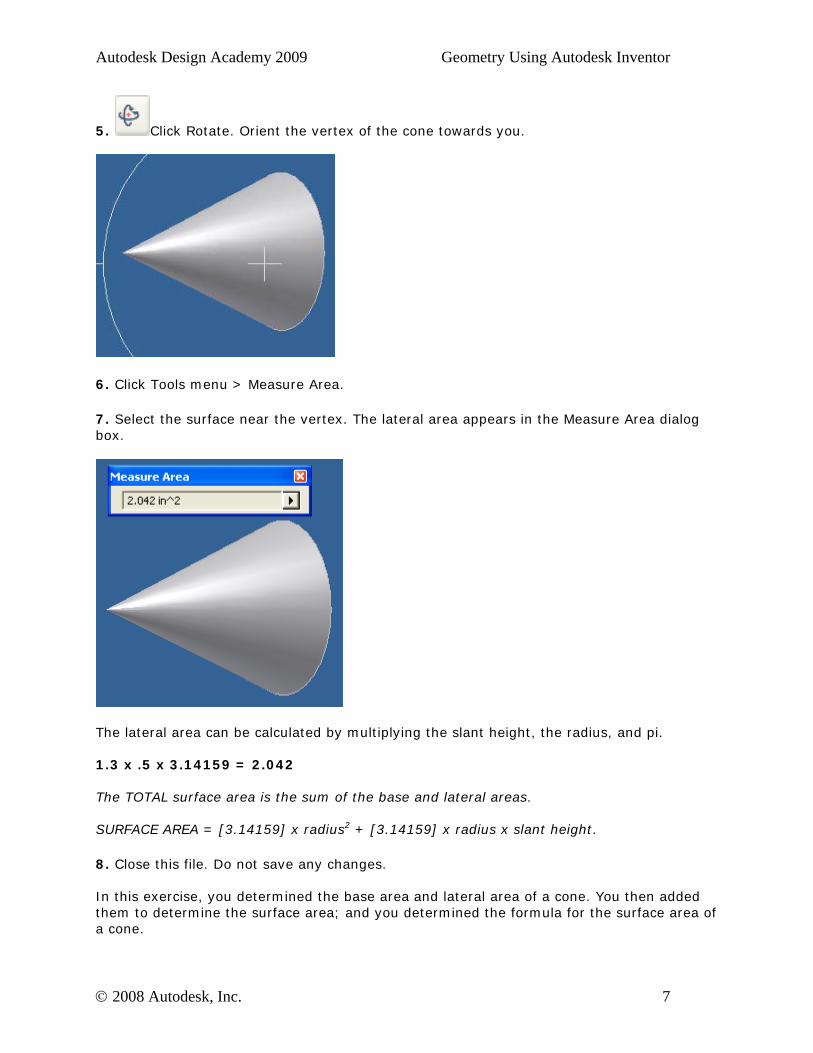
5. Click Rotate. Orient the vertex of the cone towards you.
6. Click Tools menu > Measure Area.
7. Select the surface near the vertex. The lateral area appears in the Measure Area dialog box.
The lateral area can be calculated by multiplying the slant height, the radius, and pi. 1.3 x .5 x 3.14159 = 2.042 The TOTAL surface area is the sum of the base and lateral areas. SURFACE AREA = [3.14159] x radius2 + [3.14159] x radius x slant height.
8. Close this file. Do not save any changes. In this exercise, you determined the base area and lateral area of a cone. You then added them to determine the surface area; and you determined the formula for the surface area of a cone.
© 2008 Autodesk, Inc. 7
Autodesk Design Academy 2009 Geometry Using Autodesk Inventor
Exercise 3 - Determine the Volume of a Cone
In this exercise, you determine the volume of a cone. You also determine the formula for the volume of a cone.
1. Open cone1.ipt.
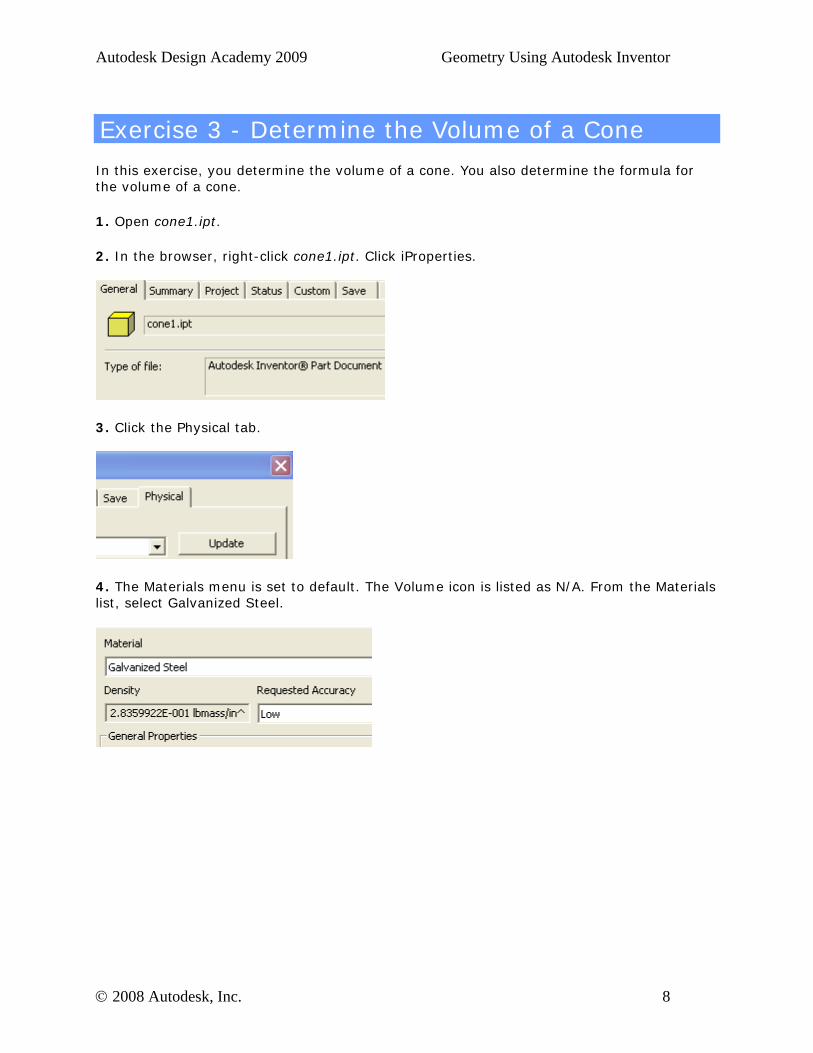
2. In the browser, right-click cone1.ipt. Click iProperties.
3. Click the Physical tab.
4. The Materials menu is set to default. The Volume icon is listed as N/A. From the Materials list, select Galvanized Steel.
© 2008 Autodesk, Inc. 8
Autodesk Design Academy 2009 Geometry Using Autodesk Inventor
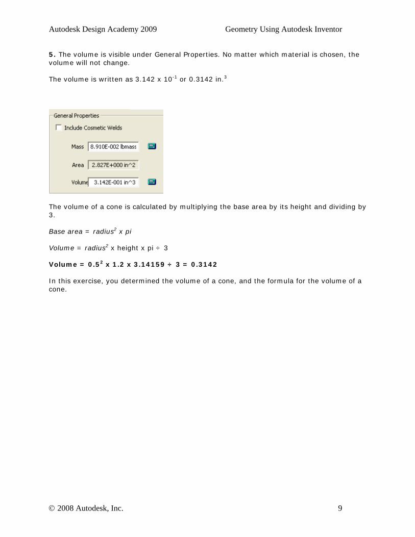
5. The volume is visible under General Properties. No matter which material is chosen, the volume will not change. The volume is written as 3.142 x 10⁻¹ or 0.3142 in.3
The volume of a cone is calculated by multiplying the base area by its height and dividing by 3. Base area = radius2 x pi Volume = radius2 x height x pi ÷ 3 Volume = 0.52 x 1.2 x 3.14159 ÷ 3 = 0.3142 In this exercise, you determined the volume of a cone, and the formula for the volume of a cone.
© 2008 Autodesk, Inc. 9

Autodesk Design Academy 2009 Geometry Using Autodesk Inventor
Lesson 2 - Congruent Triangles
About This Lesson
After completing this lesson, you will be able to:
• Construct congruent triangles. • Compare triangles for congruency. • Apply the SSS, SAS, and ASA postulates.
This lesson focuses on constructing congruent triangles and understanding why these triangles are the same size and shape.
Students construct congruent triangles using the postulates of SSS, SAS, and ASA.
Upon completion of this lesson, students will demonstrate an understanding of why triangles are congruent and why the corresponding parts of congruent triangles are congruent.
Exercises
• Congruent Triangles by SSS
• Congruent Triangles by SAS
• Congruent Triangles by ASA
© 2008 Autodesk, Inc. 10
Autodesk Design Academy 2009 Geometry Using Autodesk Inventor
Standards
Autodesk Design Academy meets content standards for Science, Technology, Engineering, Math (STEM), and Language Arts. To review the list of standards for each lesson, see the National Academic Standards Cross References document in the Printable Lessons folder.
This lesson relates to engineering and math standards.
Key Terms
congruent angles included angle
congruent segments included side
congruent triangles similar triangles
Lesson Plan
1. Review Congruent Triangles. (Demonstration) 2. Complete Exercise 1: Construct Congruent Triangles by SSS 3. Complete Exercise 2: Construct Congruent Triangles by SAS 4. Complete Exercise 3: Construct Congruent Triangles by ASA 5. Evaluate Students. (Evaluation)
© 2008 Autodesk, Inc. 11
Autodesk Design Academy 2009 Geometry Using Autodesk Inventor
Exercise 1 - Construct Congruent Triangles by SSS
In this exercise, you construct congruent triangles by creating corresponding equal sides in each triangle. If three sides of one triangle are congruent to three sides of another, the triangles are congruent.
1. Create a new IPT file using the Standard (in).ipt template.
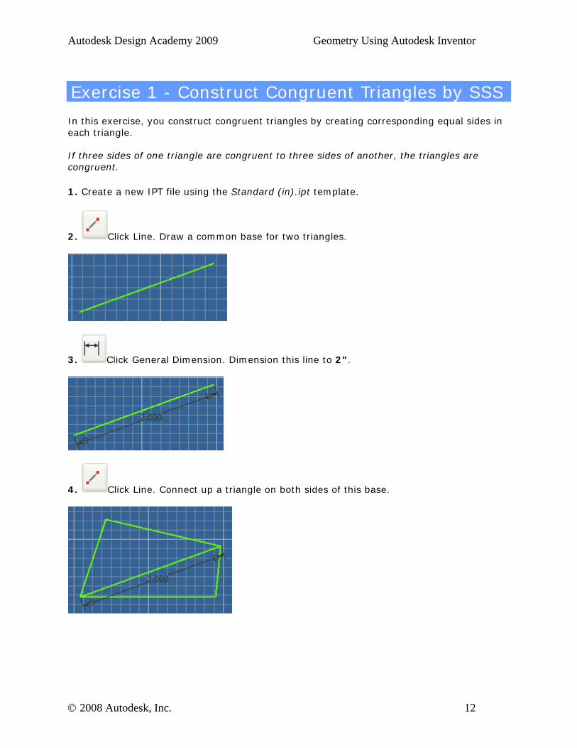
2. Click Line. Draw a common base for two triangles.
3. Click General Dimension. Dimension this line to 2".
4. Click Line. Connect up a triangle on both sides of this base.
© 2008 Autodesk, Inc. 12
Autodesk Design Academy 2009 Geometry Using Autodesk Inventor
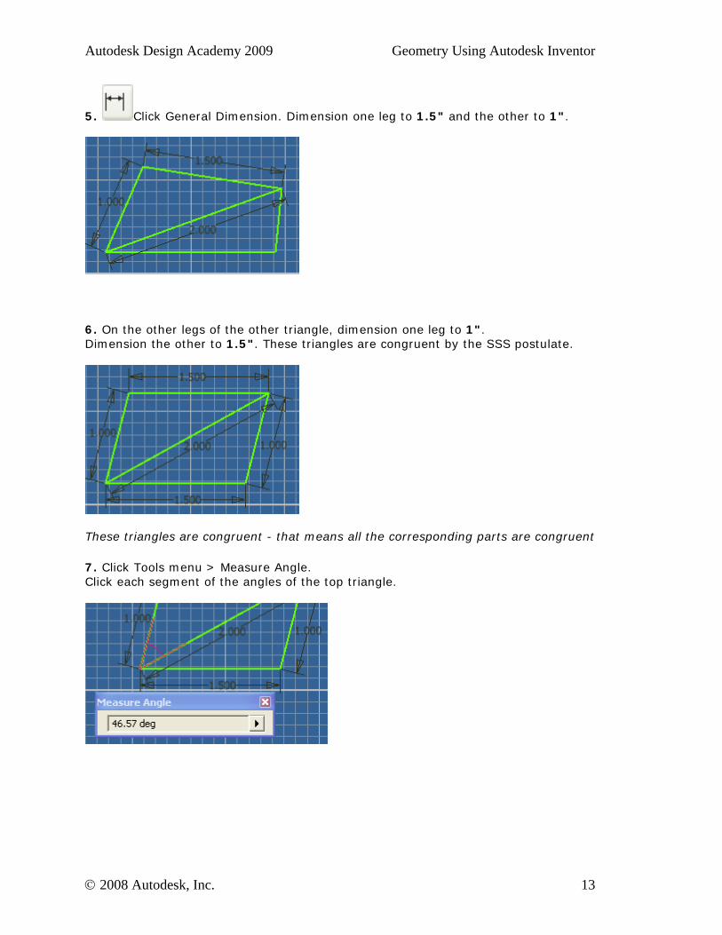
5. Click General Dimension. Dimension one leg to 1.5" and the other to 1".
6. On the other legs of the other triangle, dimension one leg to 1". Dimension the other to 1.5". These triangles are congruent by the SSS postulate.
These triangles are congruent - that means all the corresponding parts are congruent
7. Click Tools menu > Measure Angle. Click each segment of the angles of the top triangle.
© 2008 Autodesk, Inc. 13
Autodesk Design Academy 2009 Geometry Using Autodesk Inventor
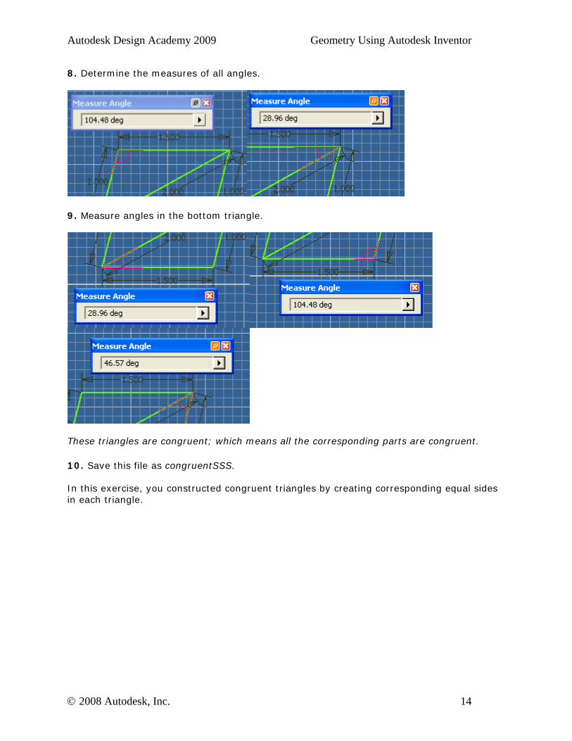
8. Determine the measures of all angles.
9. Measure angles in the bottom triangle.
These triangles are congruent; which means all the corresponding parts are congruent.
10. Save this file as congruentSSS. In this exercise, you constructed congruent triangles by creating corresponding equal sides in each triangle.
© 2008 Autodesk, Inc. 14
Autodesk Design Academy 2009 Geometry Using Autodesk Inventor
Exercise 2 - Construct Congruent Triangles by SAS
In this exercise, you construct congruent triangles by creating two equal sides and the included angle in each triangle. If two sides and the included angle of one triangle are congruent to two sides and the included angle of another, the triangles are congruent
1. Create a new IPT file using the Standard (in).ipt template.
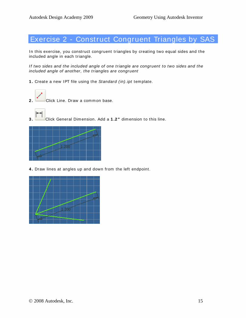
2. Click Line. Draw a common base.
3. Click General Dimension. Add a 1.2" dimension to this line.
4. Draw lines at angles up and down from the left endpoint.
© 2008 Autodesk, Inc. 15
Autodesk Design Academy 2009 Geometry Using Autodesk Inventor
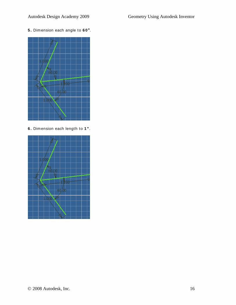
5. Dimension each angle to 60o.
6. Dimension each length to 1".
© 2008 Autodesk, Inc. 16
Autodesk Design Academy 2009 Geometry Using Autodesk Inventor
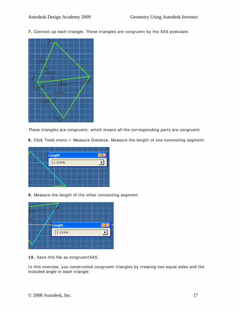
7. Connect up each triangle. These triangles are congruent by the SAS postulate.
These triangles are congruent; which means all the corresponding parts are congruent.
8. Click Tools menu > Measure Distance. Measure the length of one connecting segment.
9. Measure the length of the other connecting segment.
10. Save this file as congruentSAS. In this exercise, you constructed congruent triangles by creating two equal sides and the included angle in each triangle.
© 2008 Autodesk, Inc. 17
Autodesk Design Academy 2009 Geometry Using Autodesk Inventor
Exercise 3 - Construct Congruent Triangles by ASA
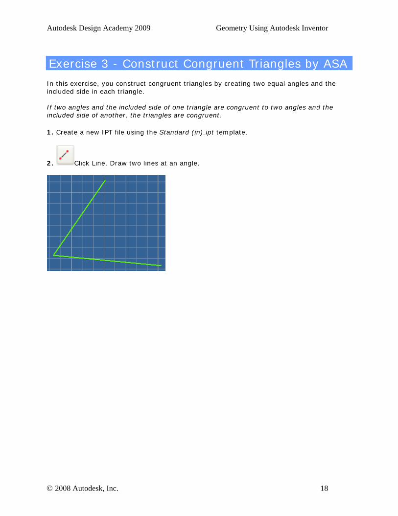
In this exercise, you construct congruent triangles by creating two equal angles and the included side in each triangle. If two angles and the included side of one triangle are congruent to two angles and the included side of another, the triangles are congruent.
1. Create a new IPT file using the Standard (in).ipt template.
2. Click Line. Draw two lines at an angle.
© 2008 Autodesk, Inc. 18
Autodesk Design Academy 2009 Geometry Using Autodesk Inventor
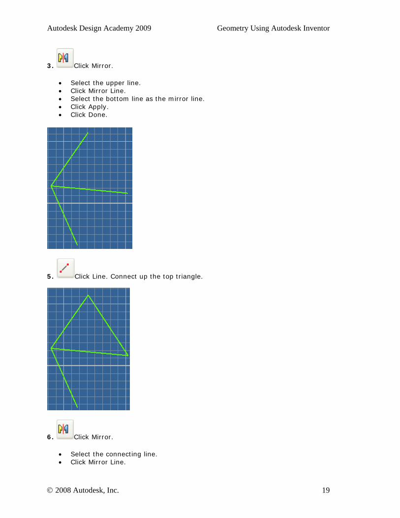
3. Click Mirror.
• Select the upper line. • Click Mirror Line. • Select the bottom line as the mirror line. • Click Apply. • Click Done.
5. Click Line. Connect up the top triangle.
6. Click Mirror.
• Select the connecting line. • Click Mirror Line.
© 2008 Autodesk, Inc. 19
Autodesk Design Academy 2009 Geometry Using Autodesk Inventor
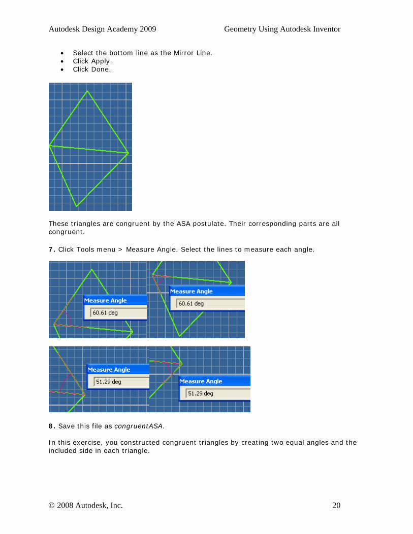
• Select the bottom line as the Mirror Line. • Click Apply. • Click Done.
These triangles are congruent by the ASA postulate. Their corresponding parts are all congruent.
7. Click Tools menu > Measure Angle. Select the lines to measure each angle.
8. Save this file as congruentASA. In this exercise, you constructed congruent triangles by creating two equal angles and the included side in each triangle.
© 2008 Autodesk, Inc. 20
Autodesk Design Academy 2009 Geometry Using Autodesk Inventor
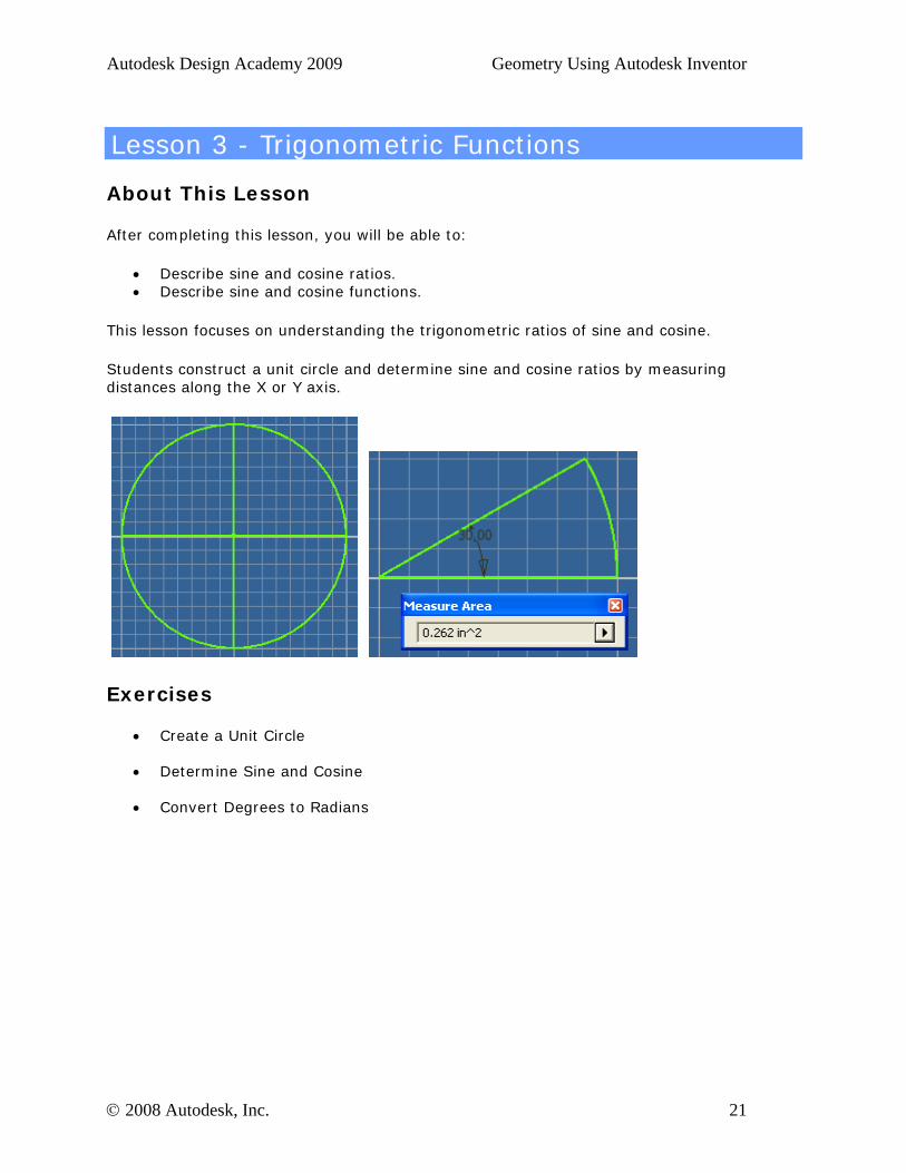
Lesson 3 - Trigonometric Functions
About This Lesson
After completing this lesson, you will be able to:
• Describe sine and cosine ratios. • Describe sine and cosine functions.
This lesson focuses on understanding the trigonometric ratios of sine and cosine.
Students construct a unit circle and determine sine and cosine ratios by measuring distances along the X or Y axis.
Exercises
• Create a Unit Circle
• Determine Sine and Cosine
• Convert Degrees to Radians
© 2008 Autodesk, Inc. 21
Autodesk Design Academy 2009 Geometry Using Autodesk Inventor
Standards
Autodesk Design Academy meets content standards for Science, Technology, Engineering, Math (STEM), and Language Arts. To review the list of standards for each lesson, see the National Academic Standards Cross References document in the Printable Lessons folder.
This lesson relates to engineering and math standards.
Key Terms
amplitude degrees phase shift sector
circumference period quadrant sine ratio
cosine ratio periodic function radians unit circle
Lesson Plan
1. Review Sine and Cosine Functions. (Demonstration) 2. Review Right Triangles. (Demonstration) 3. Complete Exercise 1: Create a Unit Circle 4. Complete Exercise 2: Determine Sine and Cosine 5. Complete Exercise 3: Convert Degrees to Radians 6. Evaluate Students. (Evaluation)
© 2008 Autodesk, Inc. 22
Autodesk Design Academy 2009 Geometry Using Autodesk Inventor
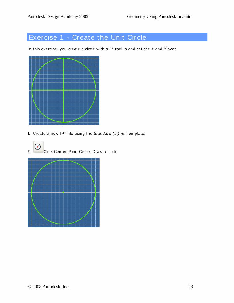
Exercise 1 - Create the Unit Circle
In this exercise, you create a circle with a 1" radius and set the X and Y axes.
1. Create a new IPT file using the Standard (in).ipt template.
2. Click Center Point Circle. Draw a circle.
© 2008 Autodesk, Inc. 23
Autodesk Design Academy 2009 Geometry Using Autodesk Inventor
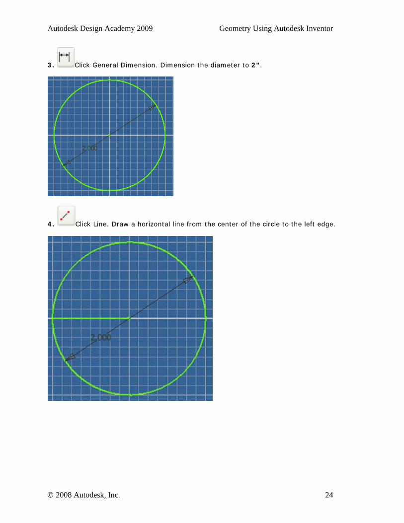
3. Click General Dimension. Dimension the diameter to 2".
4. Click Line. Draw a horizontal line from the center of the circle to the left edge.
© 2008 Autodesk, Inc. 24
Autodesk Design Academy 2009 Geometry Using Autodesk Inventor
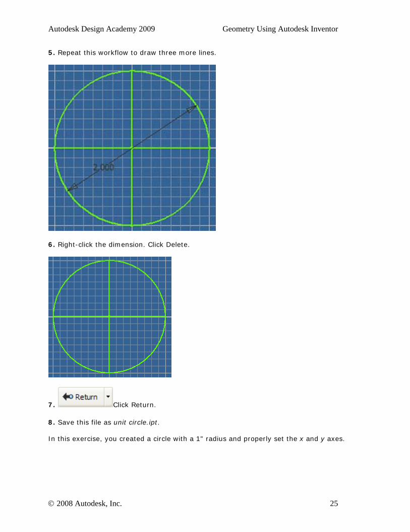
5. Repeat this workflow to draw three more lines.
6. Right-click the dimension. Click Delete.
7. Click Return.
8. Save this file as unit circle.ipt. In this exercise, you created a circle with a 1" radius and properly set the x and y axes.
© 2008 Autodesk, Inc. 25
Autodesk Design Academy 2009 Geometry Using Autodesk Inventor
Exercise 2 - Determining Sine and Cosine
In this exercise, you determine the sine and cosine ratios of an angle by measuring the distances along the x and y axes.
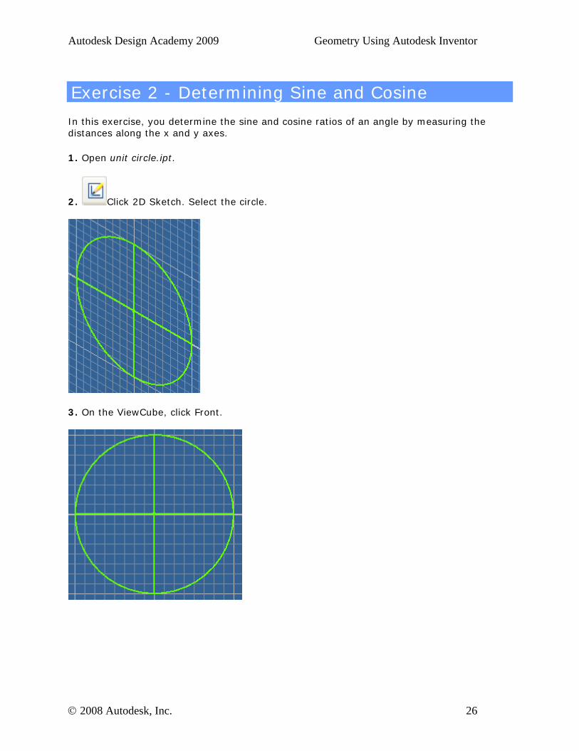
1. Open unit circle.ipt.
2. Click 2D Sketch. Select the circle.
3. On the ViewCube, click Front.
© 2008 Autodesk, Inc. 26
Autodesk Design Academy 2009 Geometry Using Autodesk Inventor
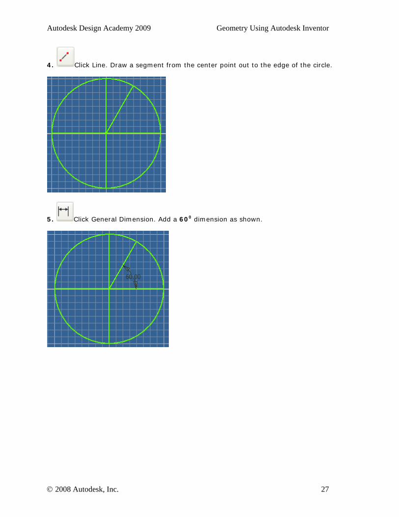
4. Click Line. Draw a segment from the center point out to the edge of the circle.
5. Click General Dimension. Add a 600 dimension as shown.
© 2008 Autodesk, Inc. 27
Autodesk Design Academy 2009 Geometry Using Autodesk Inventor
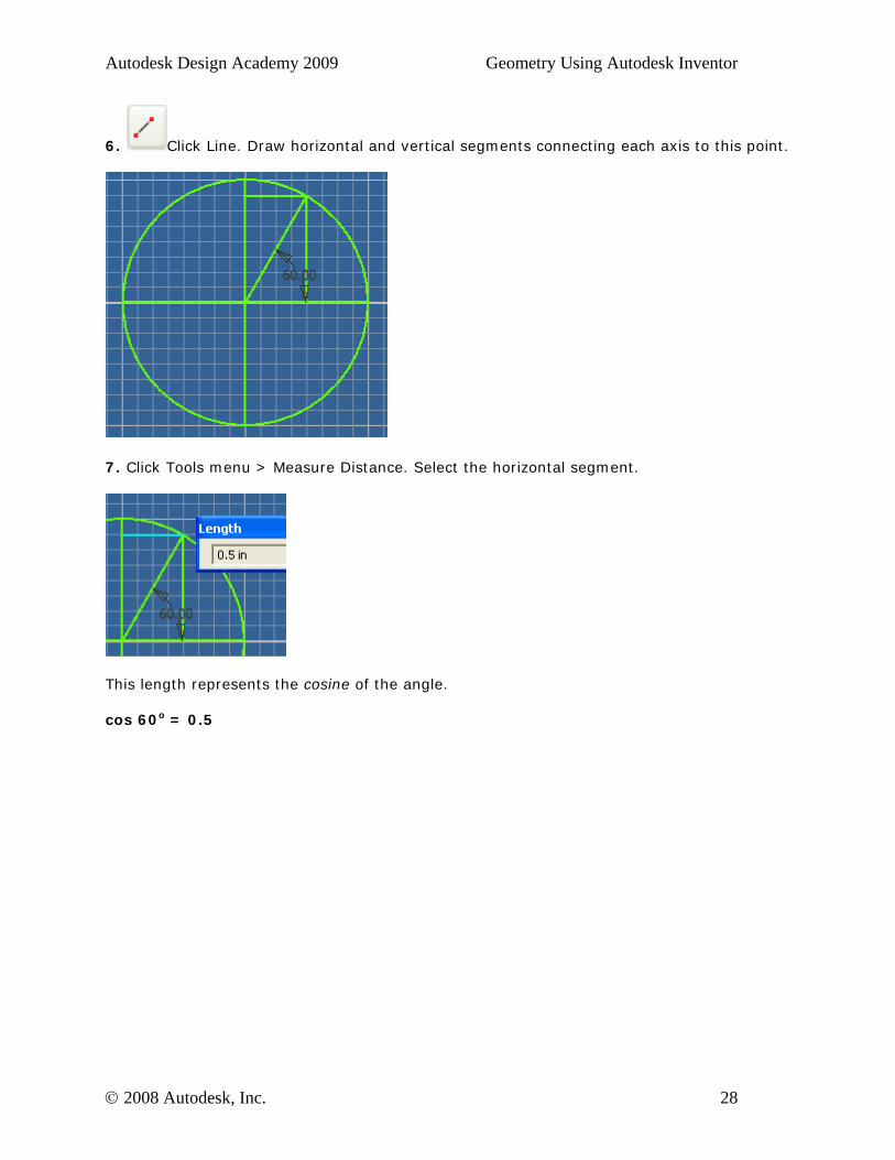
6. Click Line. Draw horizontal and vertical segments connecting each axis to this point.
7. Click Tools menu > Measure Distance. Select the horizontal segment.
This length represents the cosine of the angle. cos 60o = 0.5
© 2008 Autodesk, Inc. 28

Autodesk Design Academy 2009 Geometry Using Autodesk Inventor
8. Click Tools menu > Measure Distance. Select the vertical segment.
This length represents the sine ratio of the angle. sin 60o = 0.866
9. Close this file. Do not save any changes. In this exercise, you determined the sine and cosine ratios of an angle by measuring the distances along the x and y axes.
© 2008 Autodesk, Inc. 29
Autodesk Design Academy 2009 Geometry Using Autodesk Inventor
Exercise 3 - Converting Degrees to Radians
In this exercise, you learn to re-express angle measure from degrees to radians. Radians represent a specific arc length along the unit circle. Radians also represent a specific sector area within the unit circle.
1. Open unit circle.ipt.
2. Click 2D Sketch. Select the circle.
3. On the ViewCube, click Front.
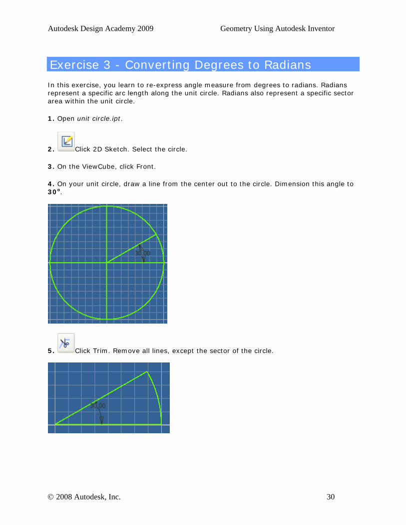
4. On your unit circle, draw a line from the center out to the circle. Dimension this angle to 30o.
5. Click Trim. Remove all lines, except the sector of the circle.
© 2008 Autodesk, Inc. 30
Autodesk Design Academy 2009 Geometry Using Autodesk Inventor
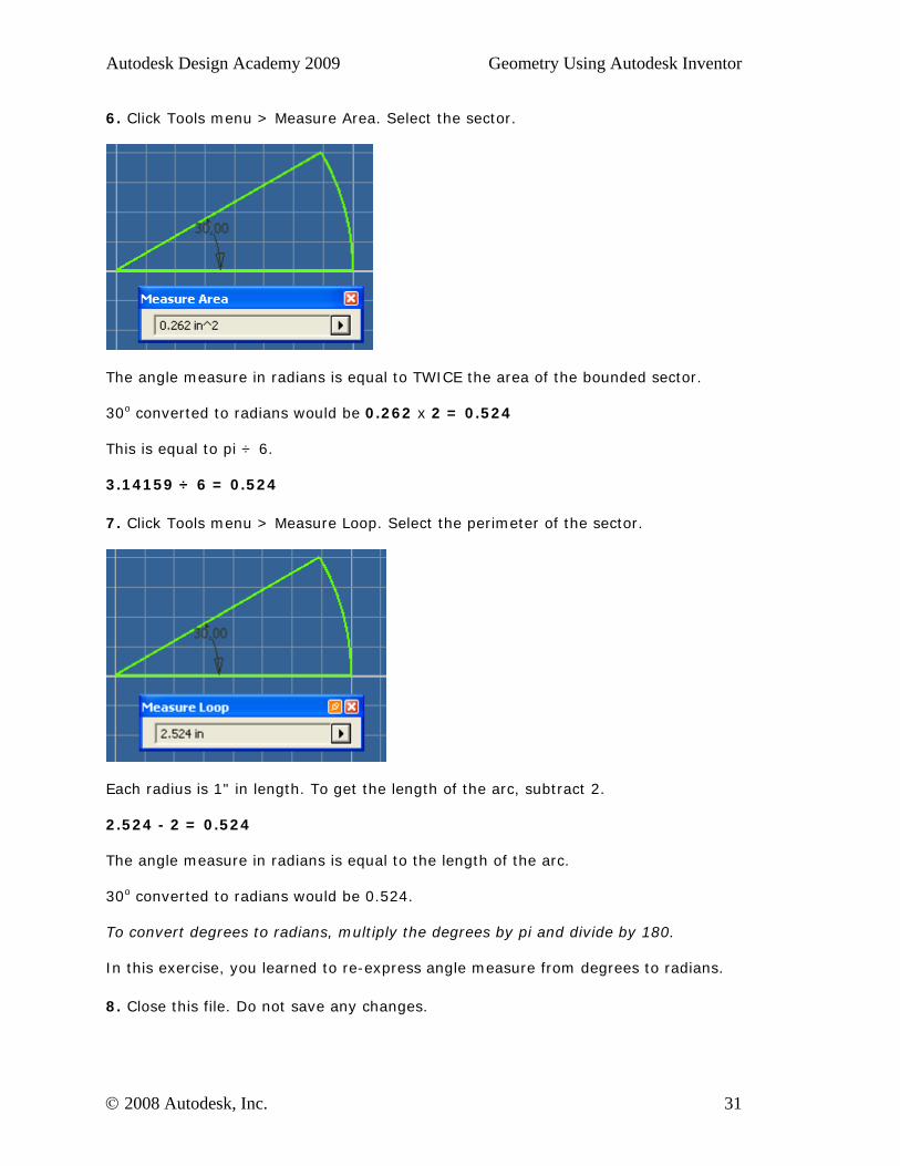
6. Click Tools menu > Measure Area. Select the sector.
The angle measure in radians is equal to TWICE the area of the bounded sector. 30o converted to radians would be 0.262 x 2 = 0.524 This is equal to pi ÷ 6. 3.14159 ÷ 6 = 0.524
7. Click Tools menu > Measure Loop. Select the perimeter of the sector.
Each radius is 1" in length. To get the length of the arc, subtract 2. 2.524 - 2 = 0.524 The angle measure in radians is equal to the length of the arc. 30o converted to radians would be 0.524. To convert degrees to radians, multiply the degrees by pi and divide by 180. In this exercise, you learned to re-express angle measure from degrees to radians.
8. Close this file. Do not save any changes.
© 2008 Autodesk, Inc. 31
Autodesk Design Academy 2009 Geometry Using Autodesk Inventor
Lesson 4 - Special Quadrilaterals
About This Lesson
After completing this lesson, you will be able to:
• Construct special four-sided figures such as parallelograms and trapezoids. • Describe the properties of the four-sided figures.
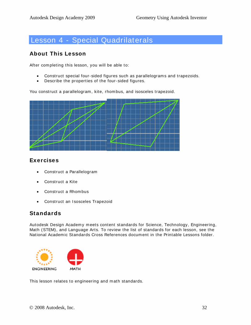
You construct a parallelogram, kite, rhombus, and isosceles trapezoid.
Exercises
• Construct a Parallelogram
• Construct a Kite
• Construct a Rhombus
• Construct an Isosceles Trapezoid
Standards
Autodesk Design Academy meets content standards for Science, Technology, Engineering, Math (STEM), and Language Arts. To review the list of standards for each lesson, see the National Academic Standards Cross References document in the Printable Lessons folder.
This lesson relates to engineering and math standards.
© 2008 Autodesk, Inc. 32
Autodesk Design Academy 2009 Geometry Using Autodesk Inventor
Key Terms
altitude convex polygon opposite angle supplementary
adjacent angle included angle opposite aide symmetry
adjacent side isosceles regular polygon vertex
Lesson Plan
1. Review properties of special quadrilaterals. (Demonstration) 2. Complete Exercise 1: Construct a Parallelogram 3. Complete Exercise 2: Construct a Kite 4. Complete Exercise 3: Construct a Rhombus 5. Complete Exercise 4: Construct an Isosceles Trapezoid 6. Evaluate Students. (Evaluation)
© 2008 Autodesk, Inc. 33
Autodesk Design Academy 2009 Geometry Using Autodesk Inventor
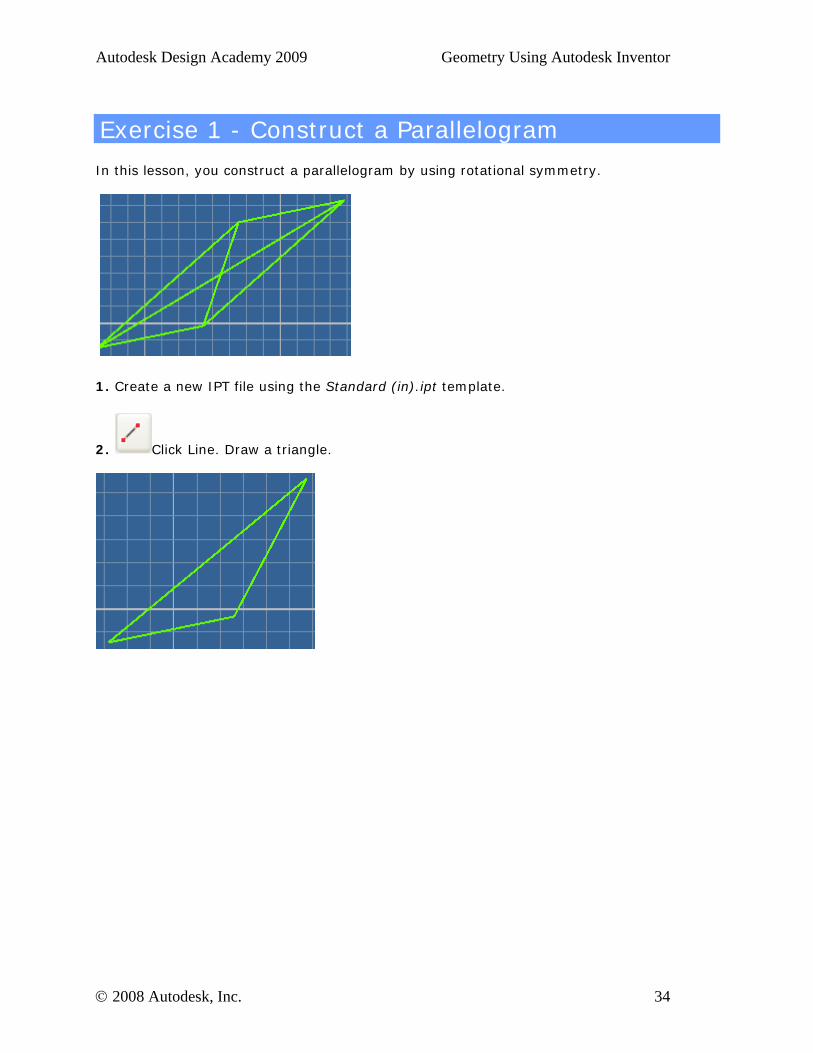
Exercise 1 - Construct a Parallelogram
In this lesson, you construct a parallelogram by using rotational symmetry.
1. Create a new IPT file using the Standard (in).ipt template.
2. Click Line. Draw a triangle.
© 2008 Autodesk, Inc. 34
Autodesk Design Academy 2009 Geometry Using Autodesk Inventor
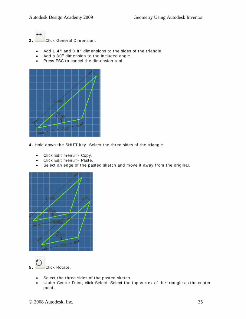
3. Click General Dimension.
• Add 1.4" and 0.8" dimensions to the sides of the triangle. • Add a 30o dimension to the included angle. • Press ESC to cancel the dimension tool.
4. Hold down the SHIFT key. Select the three sides of the triangle.
• Click Edit menu > Copy. • Click Edit menu > Paste. • Select an edge of the pasted sketch and move it away from the original.
5. Click Rotate.
• Select the three sides of the pasted sketch. • Under Center Point, click Select. Select the top vertex of the triangle as the center
point.
© 2008 Autodesk, Inc. 35
Autodesk Design Academy 2009 Geometry Using Autodesk Inventor
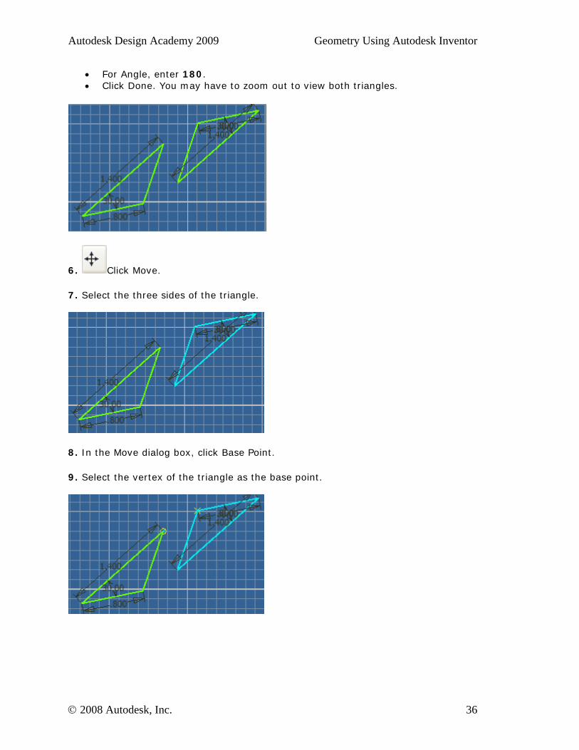
• For Angle, enter 180. • Click Done. You may have to zoom out to view both triangles.
6. Click Move.
7. Select the three sides of the triangle.
8. In the Move dialog box, click Base Point.
9. Select the vertex of the triangle as the base point.
© 2008 Autodesk, Inc. 36
Autodesk Design Academy 2009 Geometry Using Autodesk Inventor
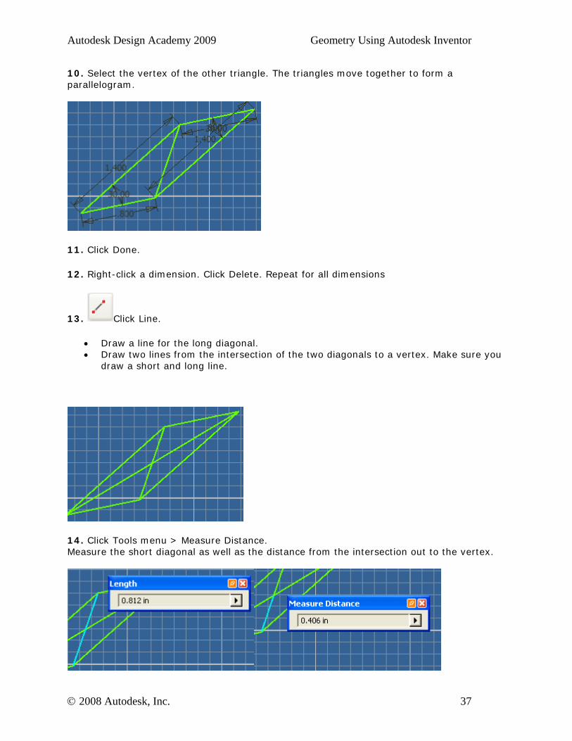
10. Select the vertex of the other triangle. The triangles move together to form a parallelogram.
11. Click Done.
12. Right-click a dimension. Click Delete. Repeat for all dimensions
13. Click Line.
• Draw a line for the long diagonal. • Draw two lines from the intersection of the two diagonals to a vertex. Make sure you
draw a short and long line.
14. Click Tools menu > Measure Distance. Measure the short diagonal as well as the distance from the intersection out to the vertex.
© 2008 Autodesk, Inc. 37
Autodesk Design Academy 2009 Geometry Using Autodesk Inventor
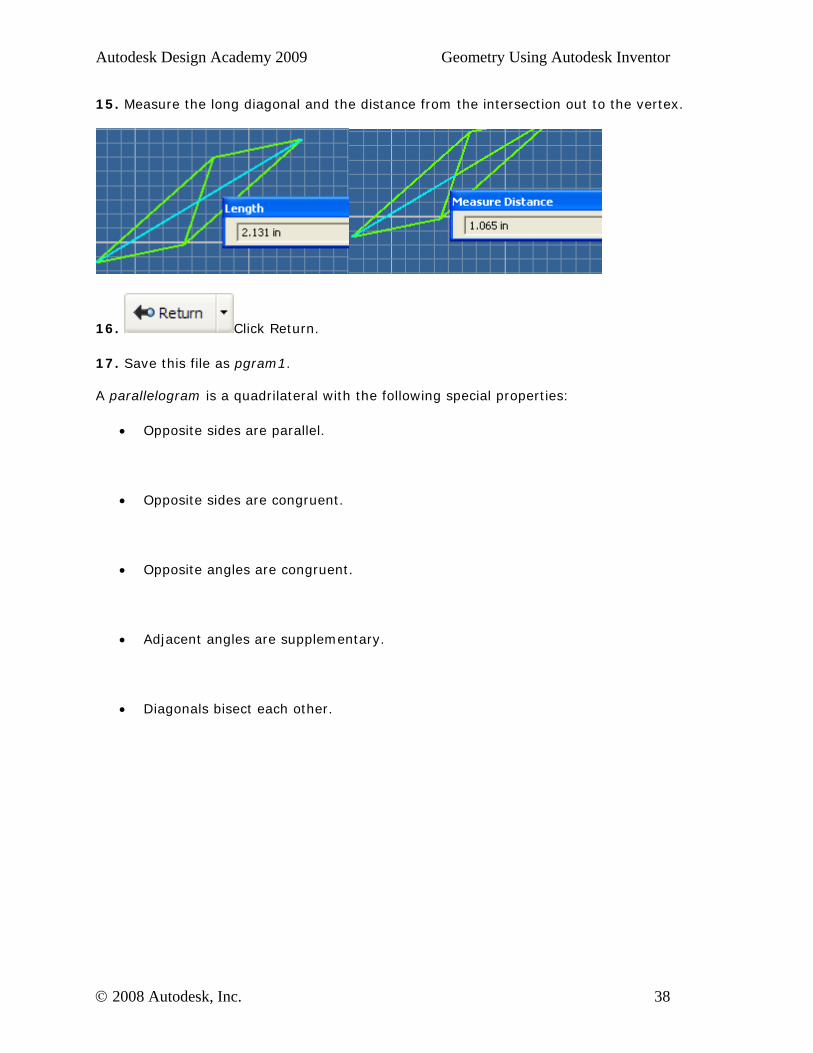
15. Measure the long diagonal and the distance from the intersection out to the vertex.
16. Click Return.
17. Save this file as pgram1. A parallelogram is a quadrilateral with the following special properties:
• Opposite sides are parallel.
• Opposite sides are congruent.
• Opposite angles are congruent.
• Adjacent angles are supplementary.
• Diagonals bisect each other.
© 2008 Autodesk, Inc. 38
Autodesk Design Academy 2009 Geometry Using Autodesk Inventor
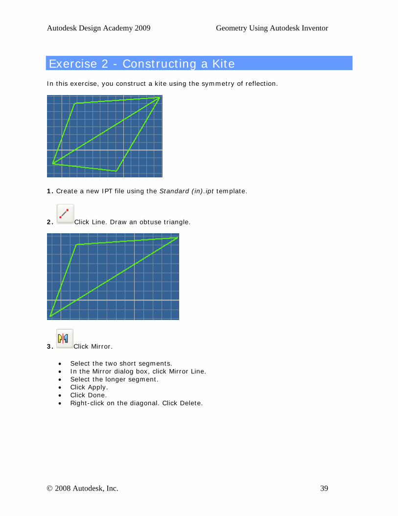
Exercise 2 - Constructing a Kite
In this exercise, you construct a kite using the symmetry of reflection.
1. Create a new IPT file using the Standard (in).ipt template.
2. Click Line. Draw an obtuse triangle.
3. Click Mirror.
• Select the two short segments. • In the Mirror dialog box, click Mirror Line. • Select the longer segment. • Click Apply. • Click Done. • Right-click on the diagonal. Click Delete.
© 2008 Autodesk, Inc. 39
Autodesk Design Academy 2009 Geometry Using Autodesk Inventor
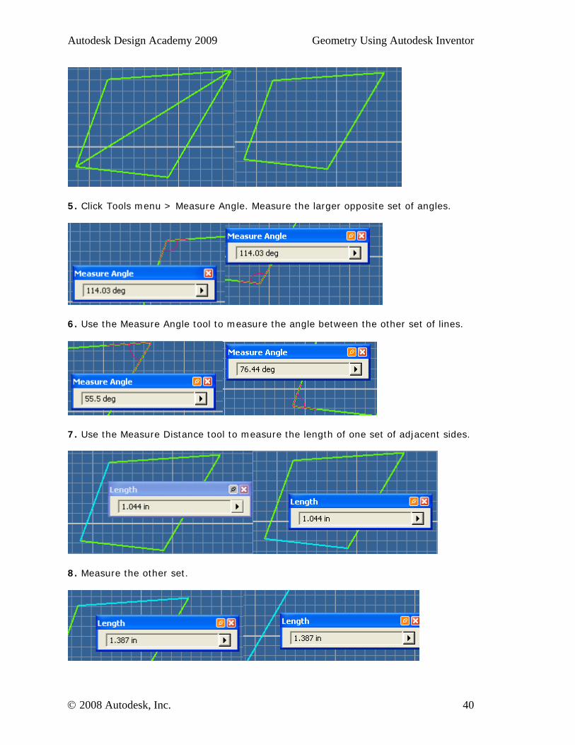
5. Click Tools menu > Measure Angle. Measure the larger opposite set of angles.
6. Use the Measure Angle tool to measure the angle between the other set of lines.
7. Use the Measure Distance tool to measure the length of one set of adjacent sides.
8. Measure the other set.
© 2008 Autodesk, Inc. 40
Autodesk Design Academy 2009 Geometry Using Autodesk Inventor
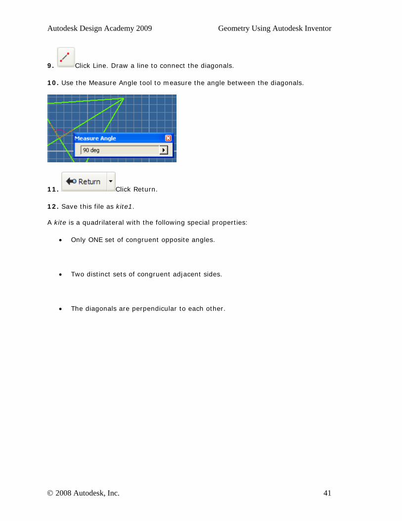
9. Click Line. Draw a line to connect the diagonals.
10. Use the Measure Angle tool to measure the angle between the diagonals.
11. Click Return.
12. Save this file as kite1. A kite is a quadrilateral with the following special properties:
• Only ONE set of congruent opposite angles.
• Two distinct sets of congruent adjacent sides.
• The diagonals are perpendicular to each other.
© 2008 Autodesk, Inc. 41
Autodesk Design Academy 2009 Geometry Using Autodesk Inventor
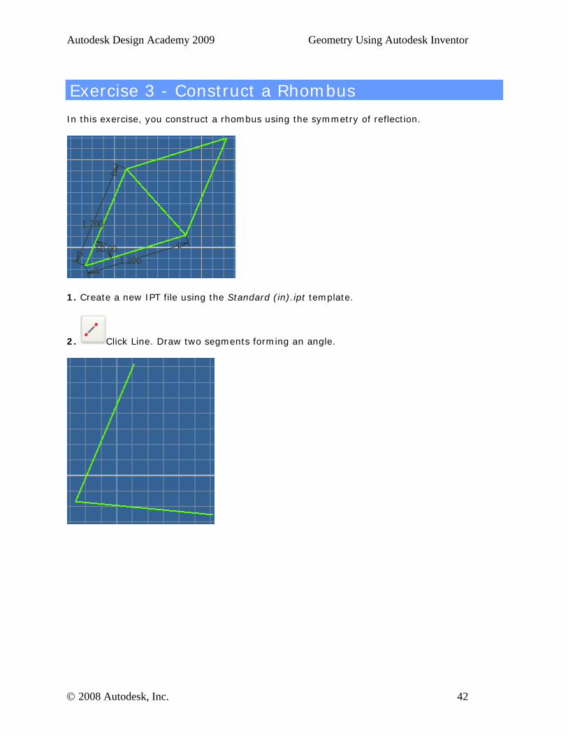
Exercise 3 - Construct a Rhombus
In this exercise, you construct a rhombus using the symmetry of reflection.
1. Create a new IPT file using the Standard (in).ipt template.
2. Click Line. Draw two segments forming an angle.
© 2008 Autodesk, Inc. 42
Autodesk Design Academy 2009 Geometry Using Autodesk Inventor
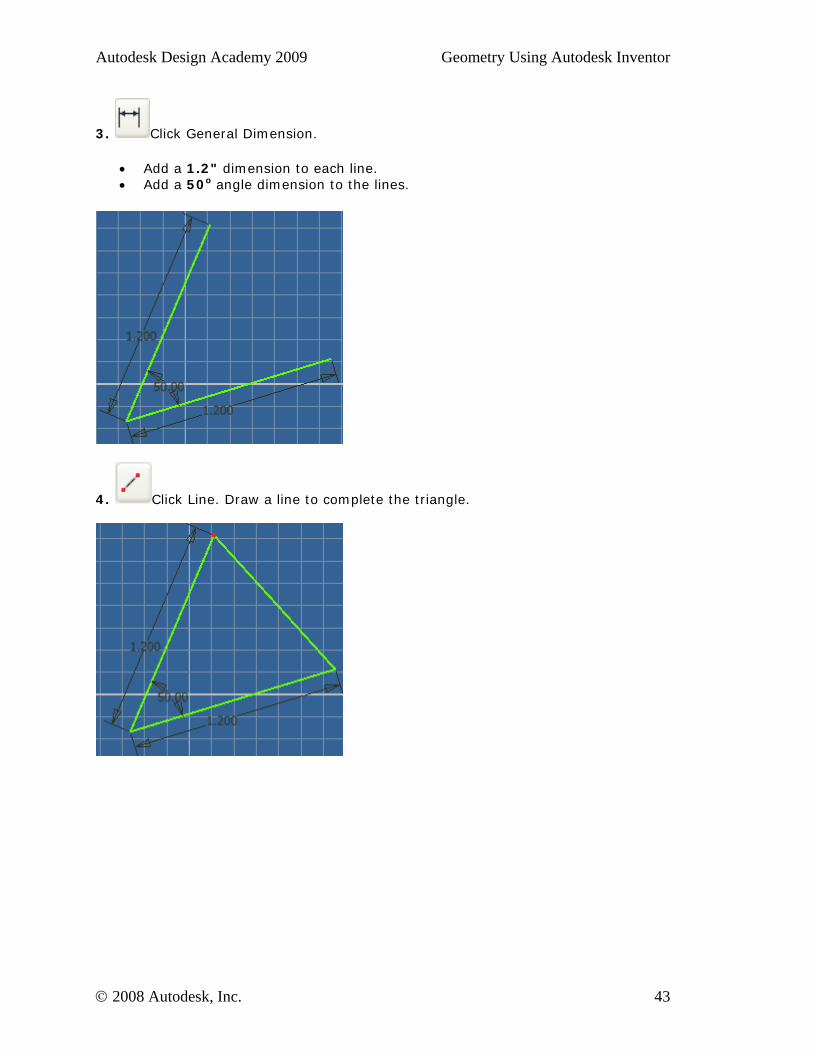
3. Click General Dimension.
• Add a 1.2" dimension to each line. • Add a 50o angle dimension to the lines.
4. Click Line. Draw a line to complete the triangle.
© 2008 Autodesk, Inc. 43
Autodesk Design Academy 2009 Geometry Using Autodesk Inventor
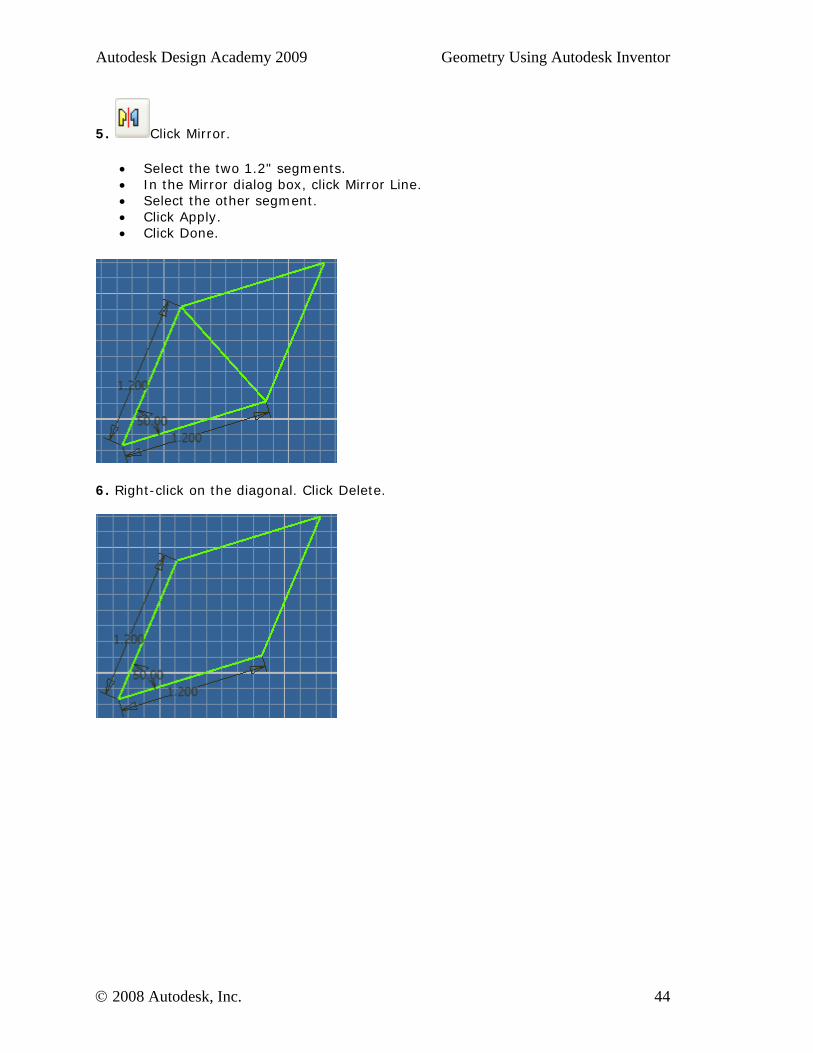
5. Click Mirror.
• Select the two 1.2" segments. • In the Mirror dialog box, click Mirror Line. • Select the other segment. • Click Apply. • Click Done.
6. Right-click on the diagonal. Click Delete.
© 2008 Autodesk, Inc. 44
Autodesk Design Academy 2009 Geometry Using Autodesk Inventor
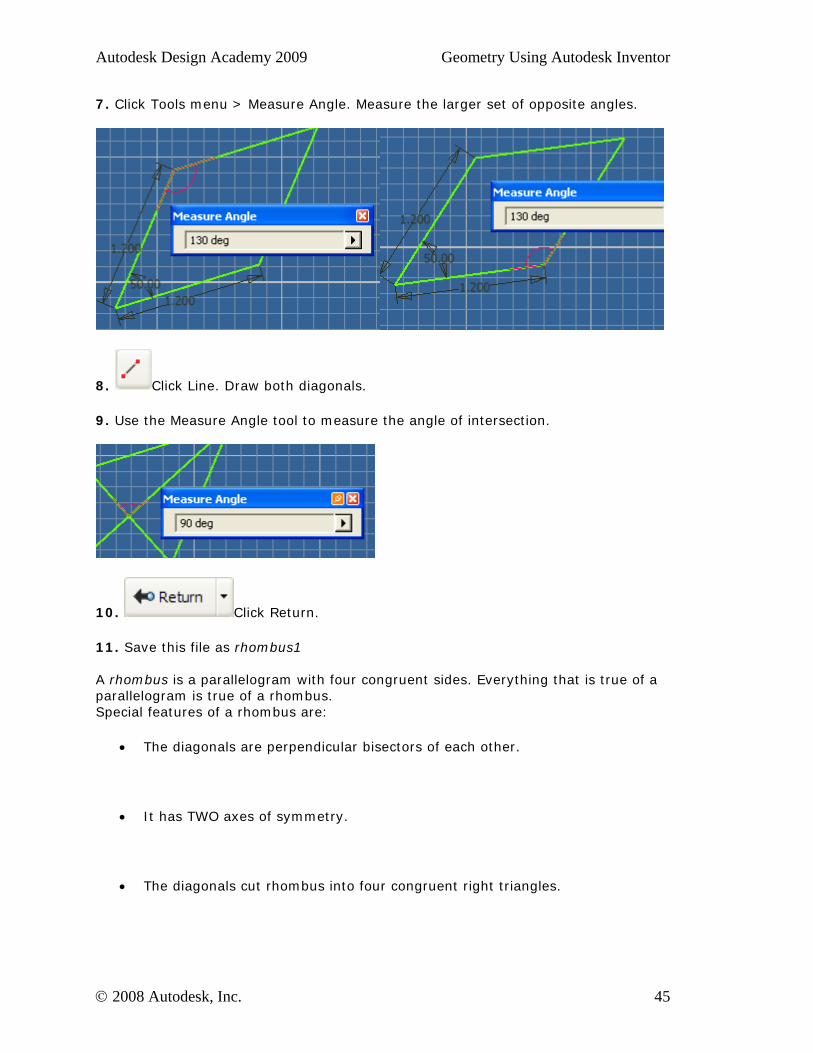
7. Click Tools menu > Measure Angle. Measure the larger set of opposite angles.
8. Click Line. Draw both diagonals.
9. Use the Measure Angle tool to measure the angle of intersection.
10. Click Return.
11. Save this file as rhombus1 A rhombus is a parallelogram with four congruent sides. Everything that is true of a parallelogram is true of a rhombus. Special features of a rhombus are:
• The diagonals are perpendicular bisectors of each other.
• It has TWO axes of symmetry.
• The diagonals cut rhombus into four congruent right triangles.
© 2008 Autodesk, Inc. 45
Autodesk Design Academy 2009 Geometry Using Autodesk Inventor
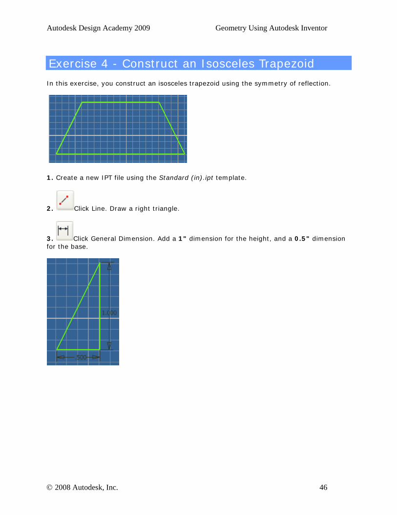
Exercise 4 - Construct an Isosceles Trapezoid
In this exercise, you construct an isosceles trapezoid using the symmetry of reflection.
1. Create a new IPT file using the Standard (in).ipt template.
2. Click Line. Draw a right triangle.
3. Click General Dimension. Add a 1" dimension for the height, and a 0.5" dimension for the base.
© 2008 Autodesk, Inc. 46
Autodesk Design Academy 2009 Geometry Using Autodesk Inventor
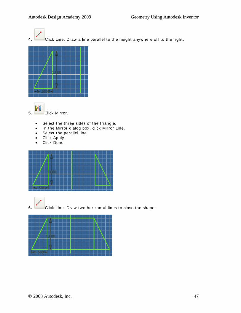
4. Click Line. Draw a line parallel to the height anywhere off to the right.
5. Click Mirror.
• Select the three sides of the triangle. • In the Mirror dialog box, click Mirror Line. • Select the parallel line. • Click Apply. • Click Done.
6. Click Line. Draw two horizontal lines to close the shape.
© 2008 Autodesk, Inc. 47
Autodesk Design Academy 2009 Geometry Using Autodesk Inventor
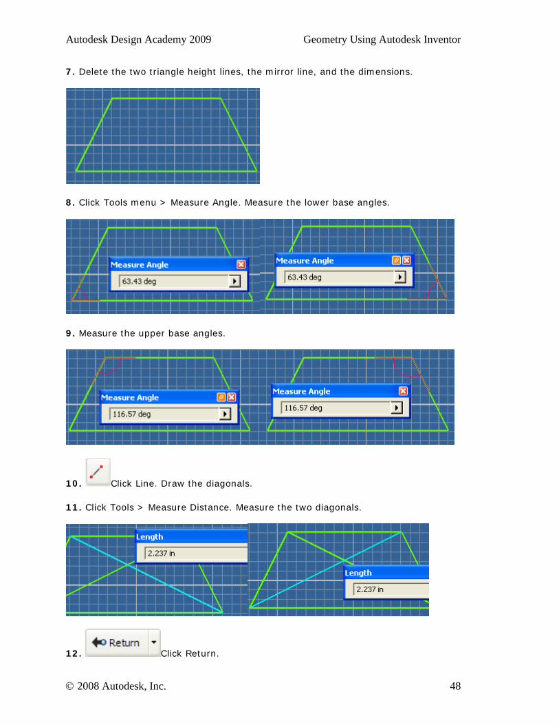
7. Delete the two triangle height lines, the mirror line, and the dimensions.
8. Click Tools menu > Measure Angle. Measure the lower base angles.
9. Measure the upper base angles.
10. Click Line. Draw the diagonals.
11. Click Tools > Measure Distance. Measure the two diagonals.
12. Click Return.
© 2008 Autodesk, Inc. 48
Autodesk Design Academy 2009 Geometry Using Autodesk Inventor
13. Save the file as trapezoid1. There are two different definitions of a trapezoid. One definition states that ONLY one set of lines is parallel. Another definition states that AT LEAST one set of lines is parallel. The special properties of the isosceles trapezoid drawn above are:
• It has two sets of congruent adjacent angles. • It has one set of parallel sides. • It has one set of congruent sides. • The diagonals are congruent.
© 2008 Autodesk, Inc. 49
Autodesk Design Academy 2009 Geometry Using Autodesk Inventor
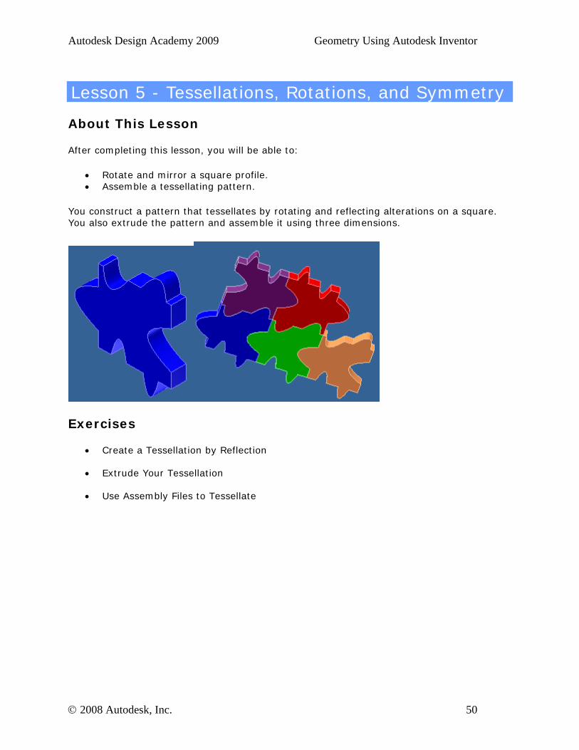
Lesson 5 - Tessellations, Rotations, and Symmetry
About This Lesson
After completing this lesson, you will be able to:
• Rotate and mirror a square profile. • Assemble a tessellating pattern.
You construct a pattern that tessellates by rotating and reflecting alterations on a square. You also extrude the pattern and assemble it using three dimensions.
Exercises
• Create a Tessellation by Reflection
• Extrude Your Tessellation
• Use Assembly Files to Tessellate
© 2008 Autodesk, Inc. 50
Autodesk Design Academy 2009 Geometry Using Autodesk Inventor
Standards
Autodesk Design Academy meets content standards for Science, Technology, Engineering, Math (STEM), and Language Arts. To review the list of standards for each lesson, see the National Academic Standards Cross References document in the Printable Lessons folder.
This lesson relates to engineering and math standards.
Key Terms
axis of symmetry reflection
diagonal rotation
plane surface symmetric
Lesson Plan
1. Review Properties of Rotation and Reflection. (Demonstration) 2. Review Properties of Tessellations. (Demonstration) 3. Complete Exercise 1: Create a Tessellation by Reflection 4. Complete Exercise 2: Extrude Your Tessellation 5. Complete Exercise 3: Use Assembly Files to Tessellate 6. Evaluate Students. (Evaluation)
© 2008 Autodesk, Inc. 51
Autodesk Design Academy 2009 Geometry Using Autodesk Inventor
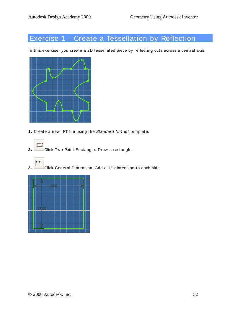
Exercise 1 - Create a Tessellation by Reflection
In this exercise, you create a 2D tessellated piece by reflecting cuts across a central axis.
1. Create a new IPT file using the Standard (in).ipt template.
2. Click Two Point Rectangle. Draw a rectangle.
3. Click General Dimension. Add a 1" dimension to each side.
© 2008 Autodesk, Inc. 52
Autodesk Design Academy 2009 Geometry Using Autodesk Inventor
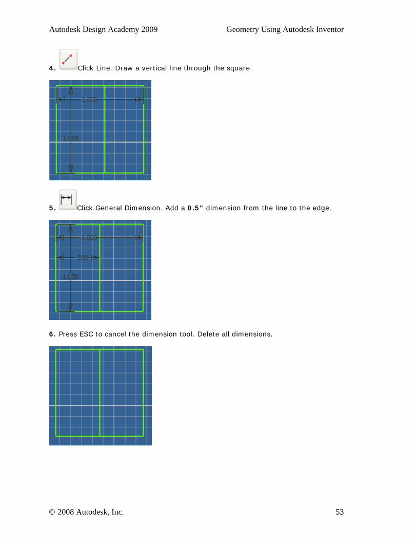
4. Click Line. Draw a vertical line through the square.
5. Click General Dimension. Add a 0.5" dimension from the line to the edge.
6. Press ESC to cancel the dimension tool. Delete all dimensions.
© 2008 Autodesk, Inc. 53
Autodesk Design Academy 2009 Geometry Using Autodesk Inventor
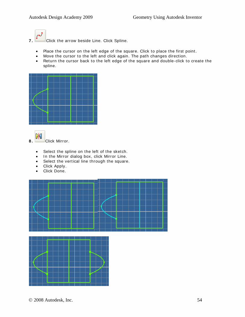
7. Click the arrow beside Line. Click Spline.
• Place the cursor on the left edge of the square. Click to place the first point. • Move the cursor to the left and click again. The path changes direction. • Return the cursor back to the left edge of the square and double-click to create the
spline.
8. Click Mirror.
• Select the spline on the left of the sketch. • In the Mirror dialog box, click Mirror Line. • Select the vertical line through the square. • Click Apply. • Click Done.
© 2008 Autodesk, Inc. 54
Autodesk Design Academy 2009 Geometry Using Autodesk Inventor
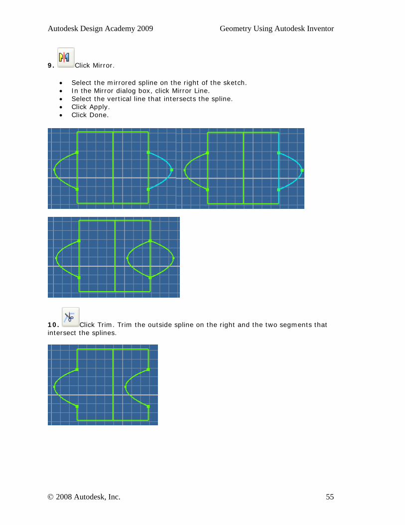
9. Click Mirror.
• Select the mirrored spline on the right of the sketch. • In the Mirror dialog box, click Mirror Line. • Select the vertical line that intersects the spline. • Click Apply. • Click Done.
10. Click Trim. Trim the outside spline on the right and the two segments that intersect the splines.
© 2008 Autodesk, Inc. 55
Autodesk Design Academy 2009 Geometry Using Autodesk Inventor
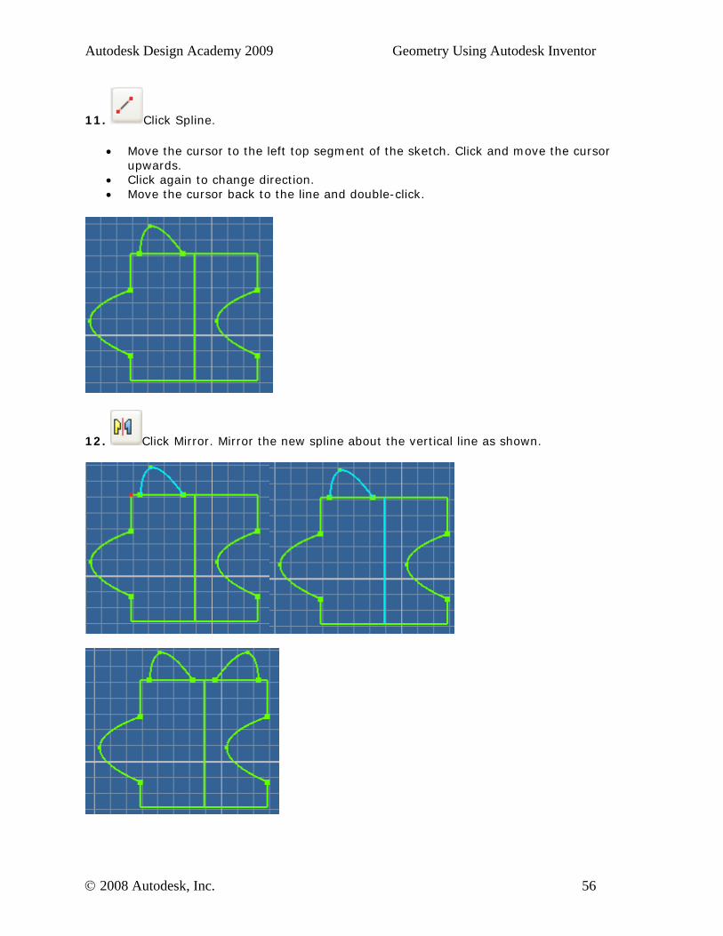
11. Click Spline.
• Move the cursor to the left top segment of the sketch. Click and move the cursor upwards.
• Click again to change direction. • Move the cursor back to the line and double-click.
12. Click Mirror. Mirror the new spline about the vertical line as shown.
© 2008 Autodesk, Inc. 56
Autodesk Design Academy 2009 Geometry Using Autodesk Inventor
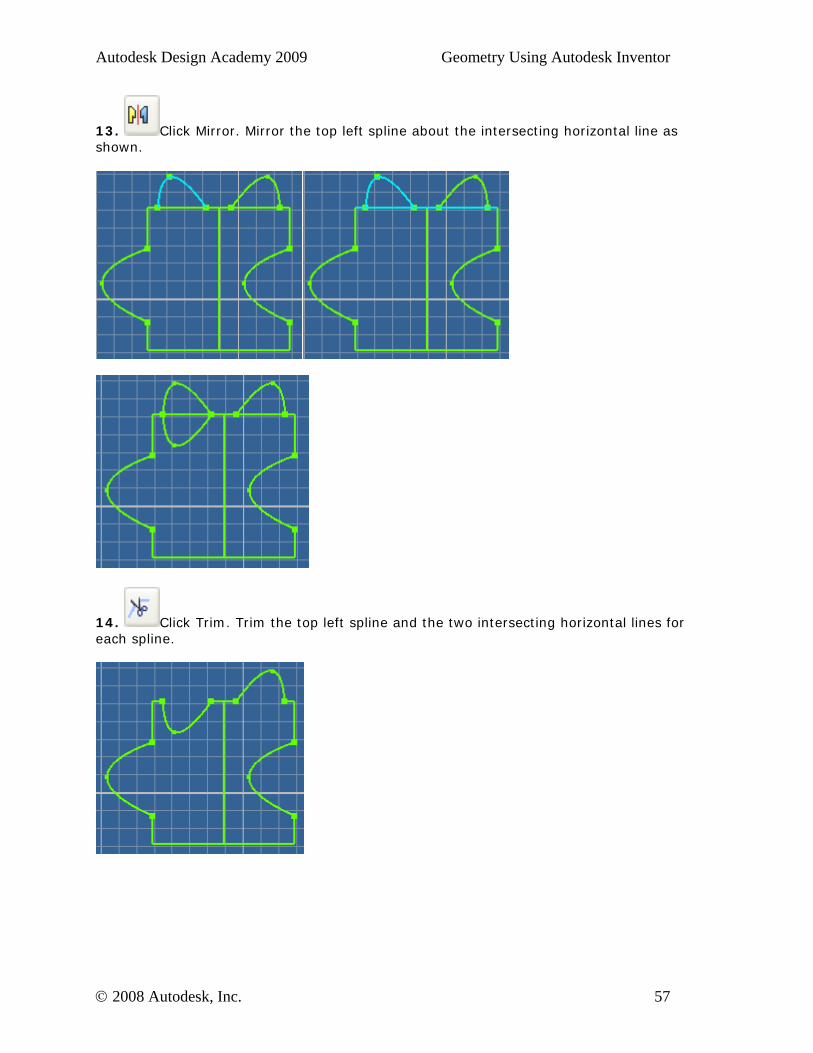
13. Click Mirror. Mirror the top left spline about the intersecting horizontal line as shown.
14. Click Trim. Trim the top left spline and the two intersecting horizontal lines for each spline.
© 2008 Autodesk, Inc. 57
Autodesk Design Academy 2009 Geometry Using Autodesk Inventor
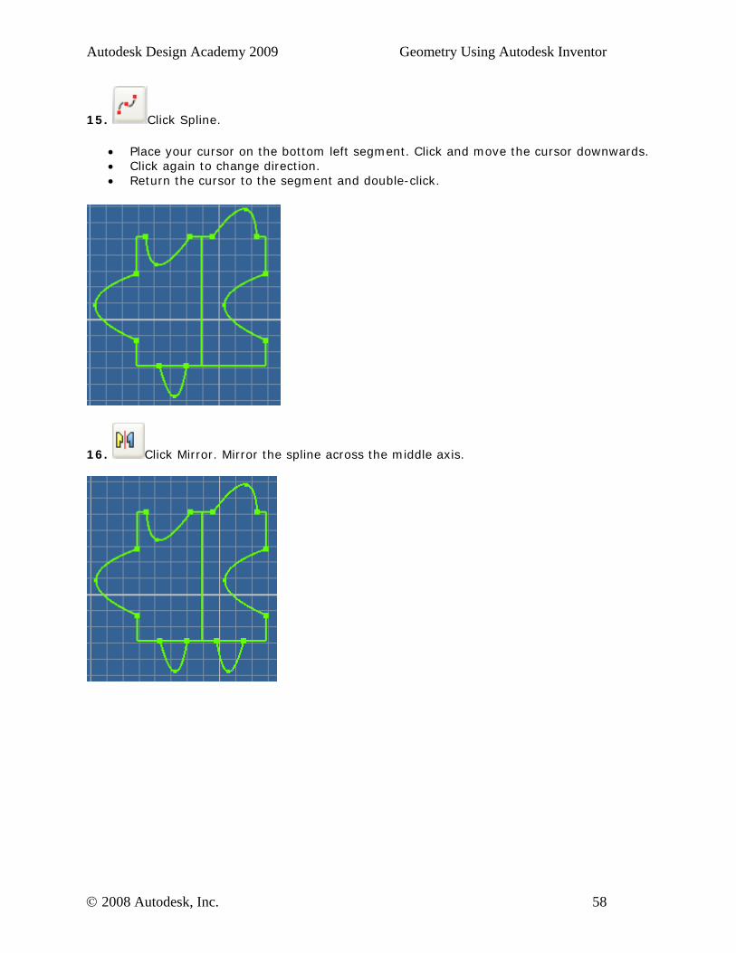
15. Click Spline.
• Place your cursor on the bottom left segment. Click and move the cursor downwards. • Click again to change direction. • Return the cursor to the segment and double-click.
16. Click Mirror. Mirror the spline across the middle axis.
© 2008 Autodesk, Inc. 58
Autodesk Design Academy 2009 Geometry Using Autodesk Inventor
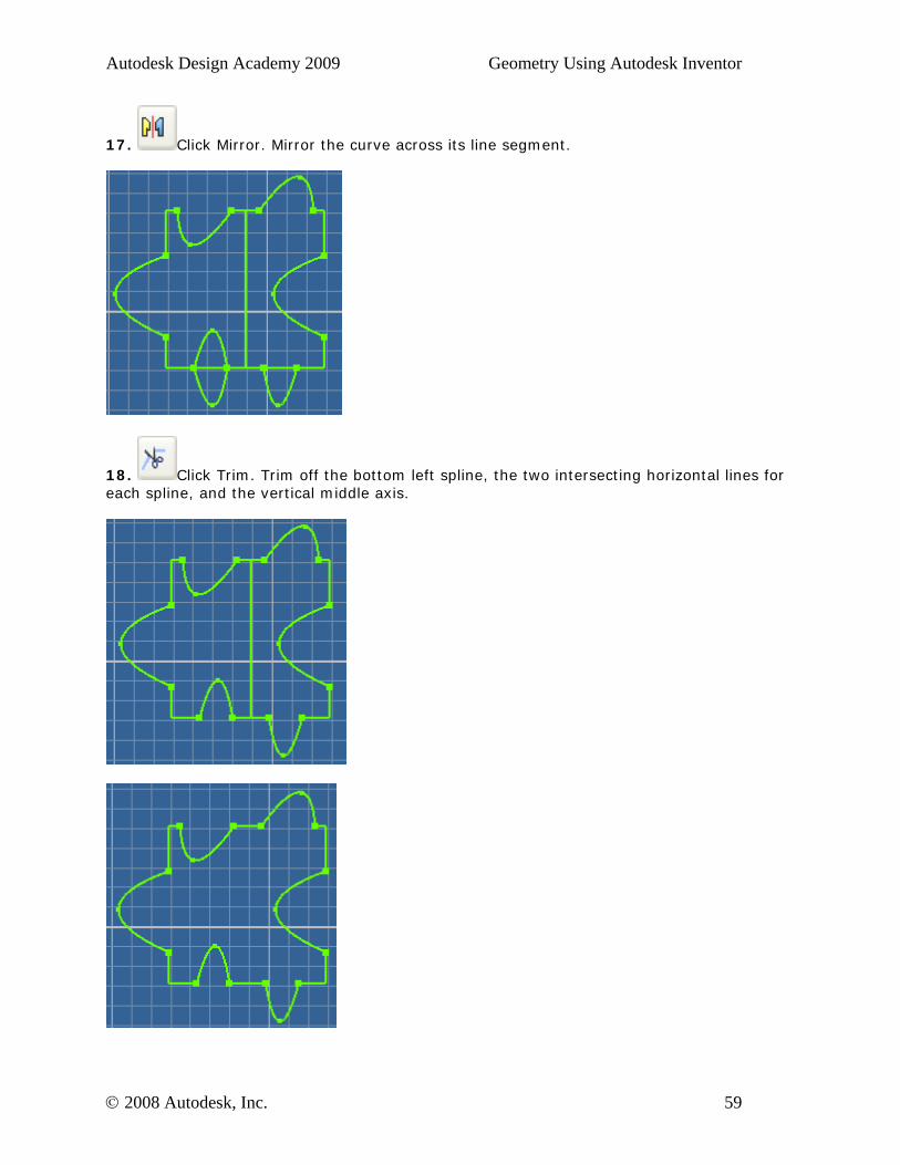
17. Click Mirror. Mirror the curve across its line segment.
18. Click Trim. Trim off the bottom left spline, the two intersecting horizontal lines for each spline, and the vertical middle axis.
© 2008 Autodesk, Inc. 59

Autodesk Design Academy 2009 Geometry Using Autodesk Inventor
19. Click Return.
20. Save the file as 1tess.ipt. In this exercise, you created a 2D tessellated piece by reflecting cuts across a central axis.
© 2008 Autodesk, Inc. 60

Autodesk Design Academy 2009 Geometry Using Autodesk Inventor
Exercise 2 - Extrude Your Tessellation
In this exercise, you create a 3D tessellated piece from your 2D tessellated piece.
1. Open tess1.ipt file.
2. On the ViewCube, click Front.
3. Click Extrude.
• For Distance, enter 0.2". • Click OK.
© 2008 Autodesk, Inc. 61
Autodesk Design Academy 2009 Geometry Using Autodesk Inventor
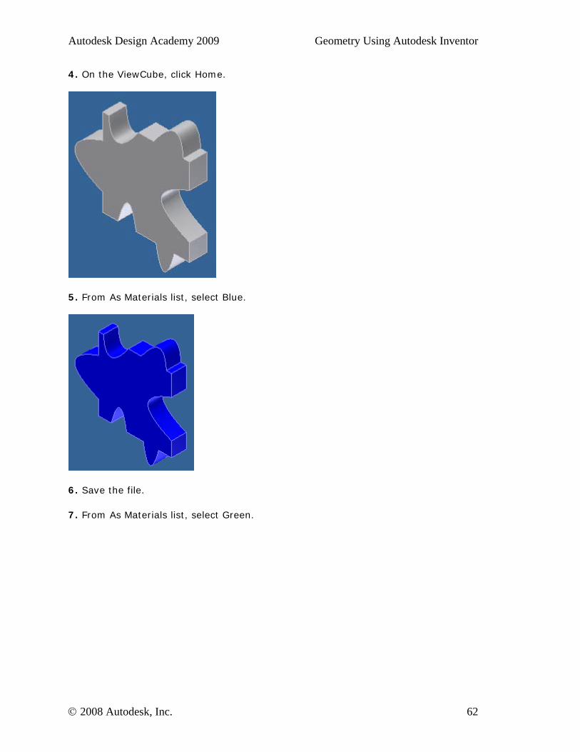
4. On the ViewCube, click Home.
5. From As Materials list, select Blue.
6. Save the file.
7. From As Materials list, select Green.
© 2008 Autodesk, Inc. 62
Autodesk Design Academy 2009 Geometry Using Autodesk Inventor
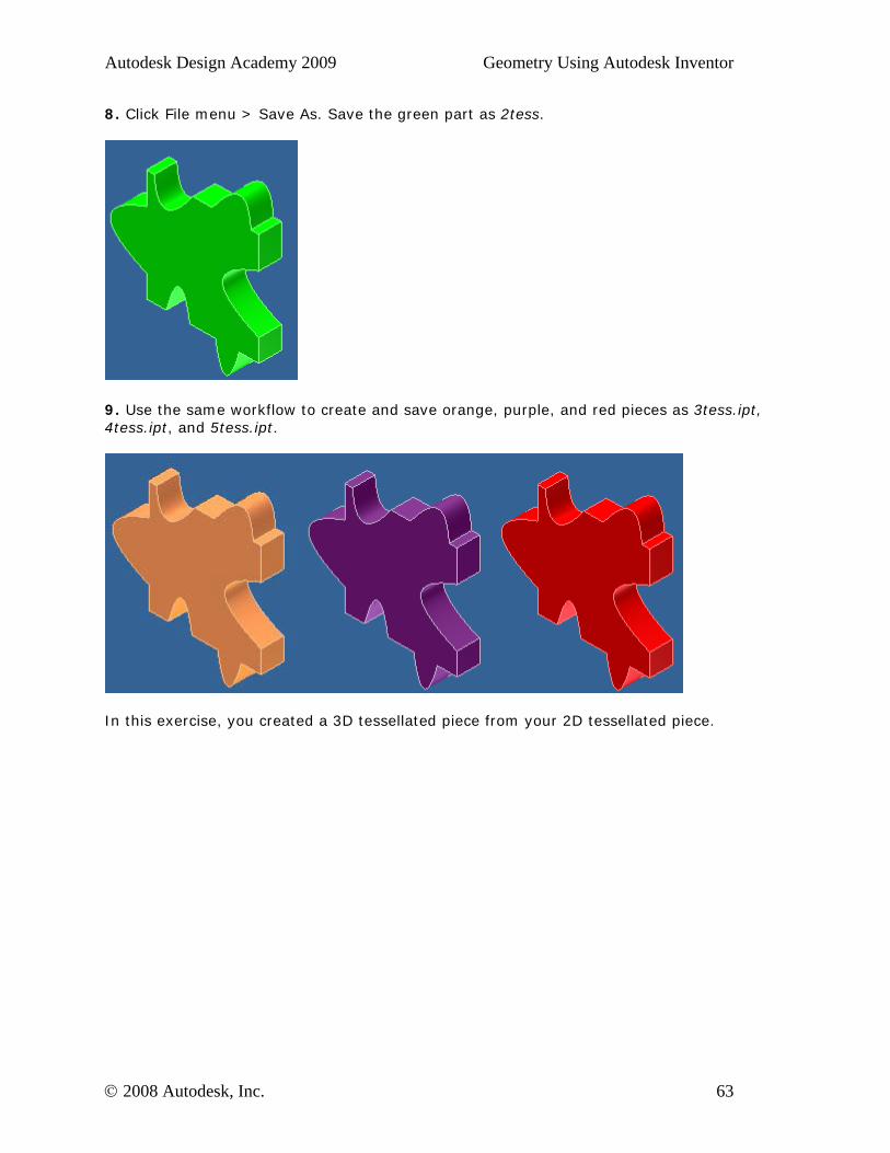
8. Click File menu > Save As. Save the green part as 2tess.
9. Use the same workflow to create and save orange, purple, and red pieces as 3tess.ipt, 4tess.ipt, and 5tess.ipt.
In this exercise, you created a 3D tessellated piece from your 2D tessellated piece.
© 2008 Autodesk, Inc. 63
Autodesk Design Academy 2009 Geometry Using Autodesk Inventor
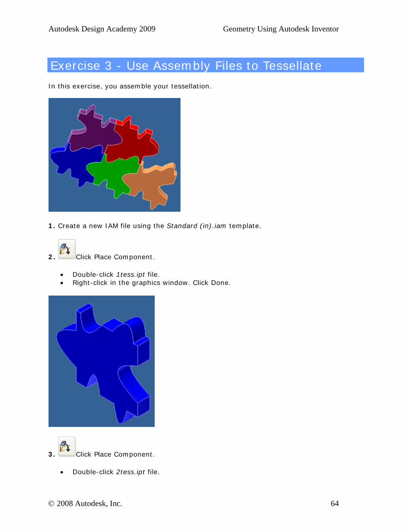
Exercise 3 - Use Assembly Files to Tessellate
In this exercise, you assemble your tessellation.
1. Create a new IAM file using the Standard (in).iam template.
2. Click Place Component.
• Double-click 1tess.ipt file. • Right-click in the graphics window. Click Done.
3. Click Place Component.
• Double-click 2tess.ipt file.
© 2008 Autodesk, Inc. 64
Autodesk Design Academy 2009 Geometry Using Autodesk Inventor
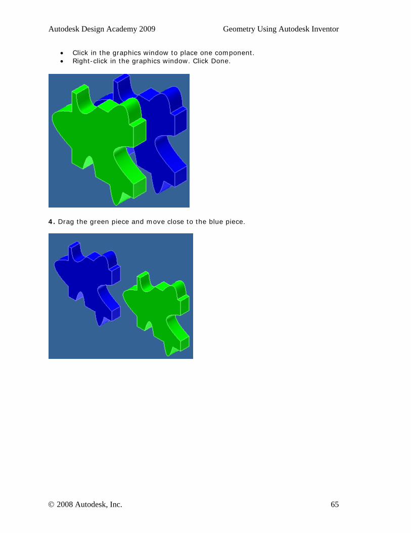
• Click in the graphics window to place one component. • Right-click in the graphics window. Click Done.
4. Drag the green piece and move close to the blue piece.
© 2008 Autodesk, Inc. 65
Autodesk Design Academy 2009 Geometry Using Autodesk Inventor
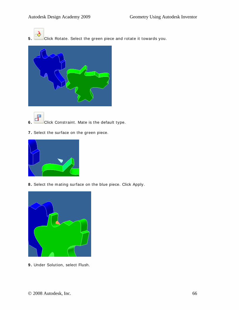
5. Click Rotate. Select the green piece and rotate it towards you.
6. Click Constraint. Mate is the default type.
7. Select the surface on the green piece.
8. Select the mating surface on the blue piece. Click Apply.
9. Under Solution, select Flush.
© 2008 Autodesk, Inc. 66
Autodesk Design Academy 2009 Geometry Using Autodesk Inventor
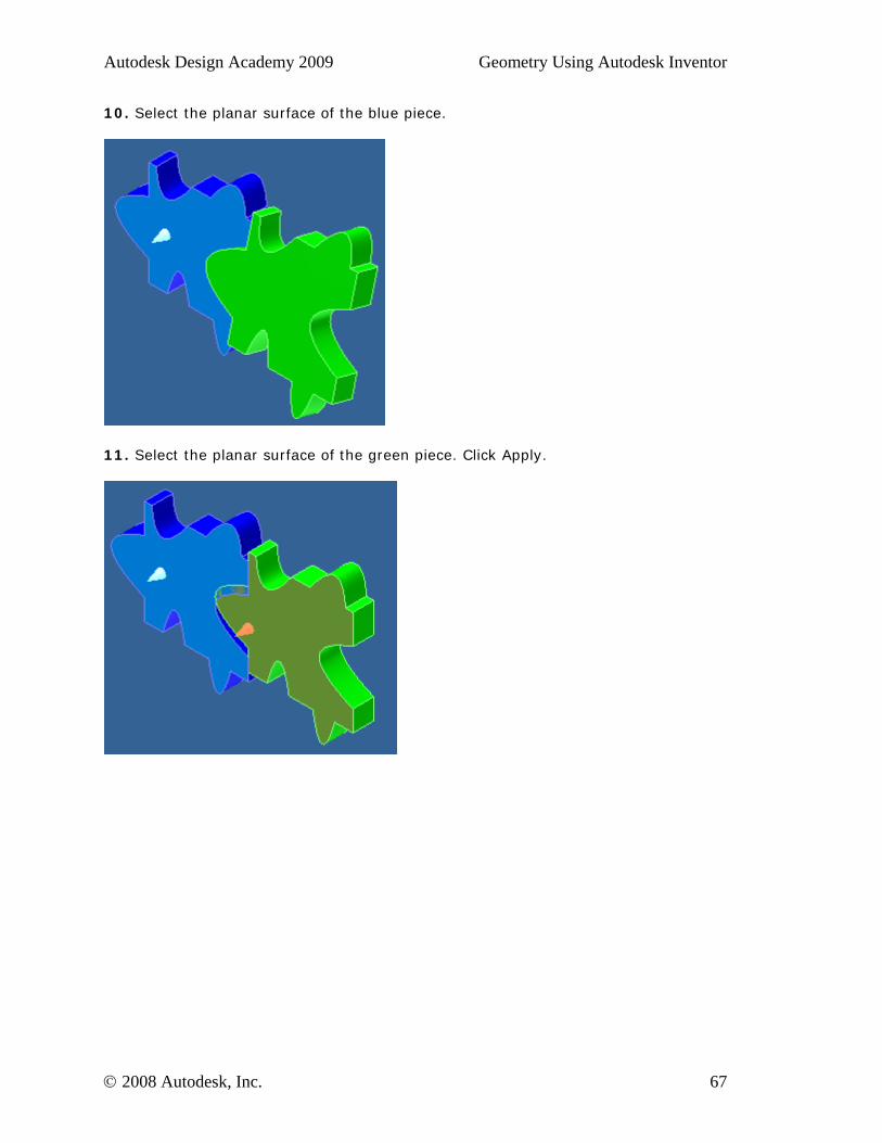
10. Select the planar surface of the blue piece.
11. Select the planar surface of the green piece. Click Apply.
© 2008 Autodesk, Inc. 67
Autodesk Design Academy 2009 Geometry Using Autodesk Inventor
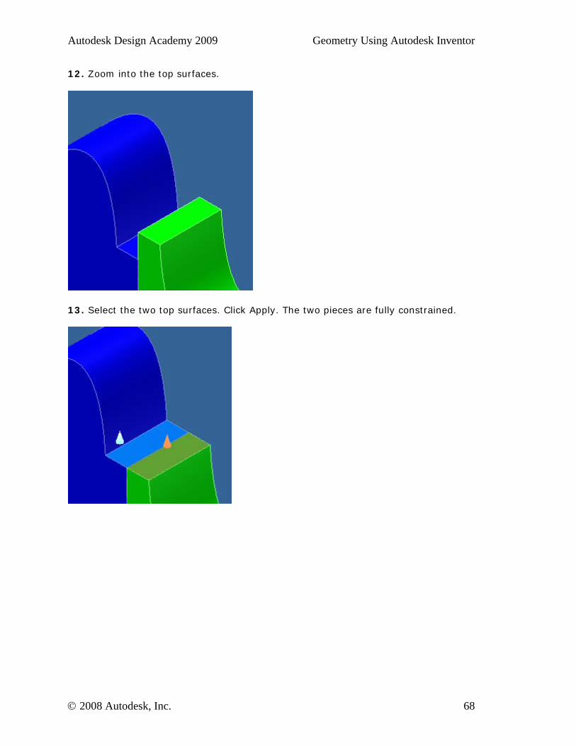
12. Zoom into the top surfaces.
13. Select the two top surfaces. Click Apply. The two pieces are fully constrained.
© 2008 Autodesk, Inc. 68
Autodesk Design Academy 2009 Geometry Using Autodesk Inventor
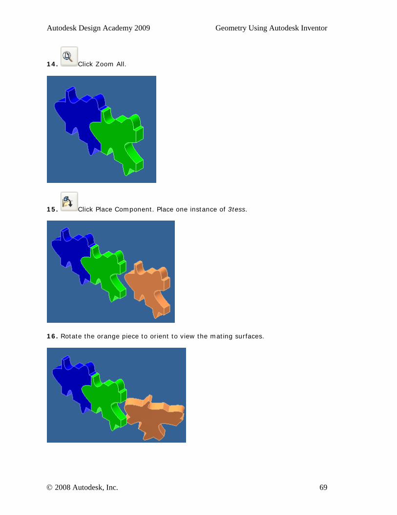
14. Click Zoom All.
15. Click Place Component. Place one instance of 3tess.
16. Rotate the orange piece to orient to view the mating surfaces.
© 2008 Autodesk, Inc. 69
Autodesk Design Academy 2009 Geometry Using Autodesk Inventor
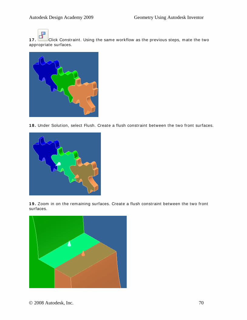
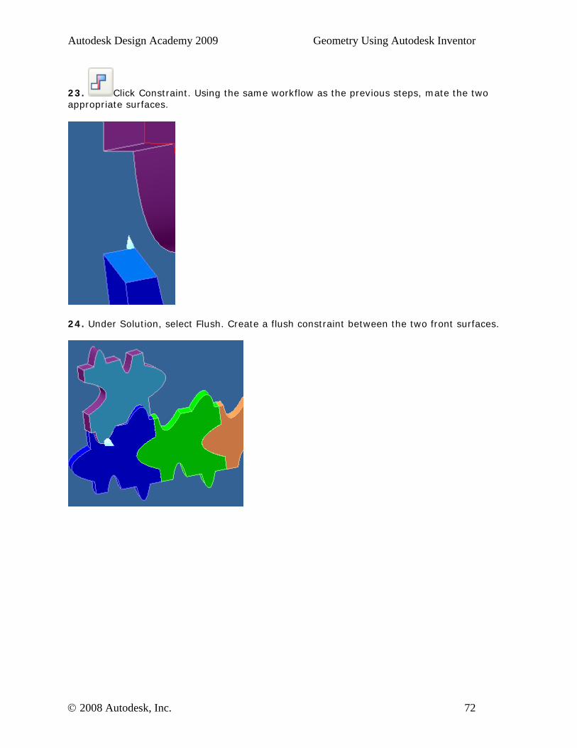
17. Click Constraint. Using the same workflow as the previous steps, mate the two appropriate surfaces.
18. Under Solution, select Flush. Create a flush constraint between the two front surfaces.
19. Zoom in on the remaining surfaces. Create a flush constraint between the two front surfaces.
© 2008 Autodesk, Inc. 70
Autodesk Design Academy 2009 Geometry Using Autodesk Inventor
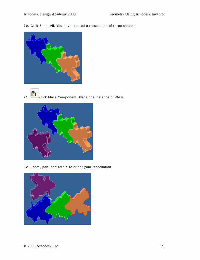
20. Click Zoom All. You have created a tessellation of three shapes.
21. Click Place Component. Place one instance of 4tess.
22. Zoom, pan, and rotate to orient your tessellation.
© 2008 Autodesk, Inc. 71
Autodesk Design Academy 2009 Geometry Using Autodesk Inventor
23. Click Constraint. Using the same workflow as the previous steps, mate the two appropriate surfaces.
24. Under Solution, select Flush. Create a flush constraint between the two front surfaces.
© 2008 Autodesk, Inc. 72

Autodesk Design Academy 2009 Geometry Using Autodesk Inventor
25. Zoom in on the remaining surfaces. Create a flush constraint between the two front surfaces.
26. Click Zoom All. You now have a four piece tessellation.
27. Click Place Component. Place one instance of 5tess.
© 2008 Autodesk, Inc. 73
Autodesk Design Academy 2009 Geometry Using Autodesk Inventor
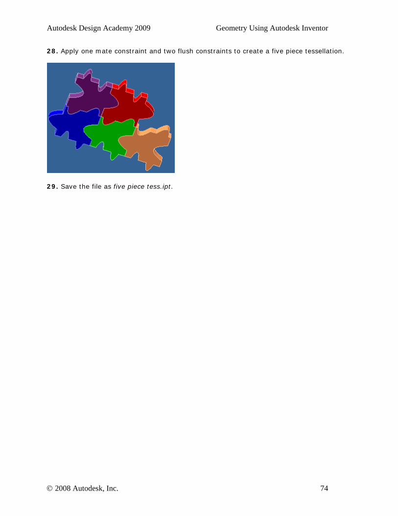
28. Apply one mate constraint and two flush constraints to create a five piece tessellation.
29. Save the file as five piece tess.ipt.
© 2008 Autodesk, Inc. 74
Autodesk Design Academy 2009 Geometry Using Autodesk Inventor
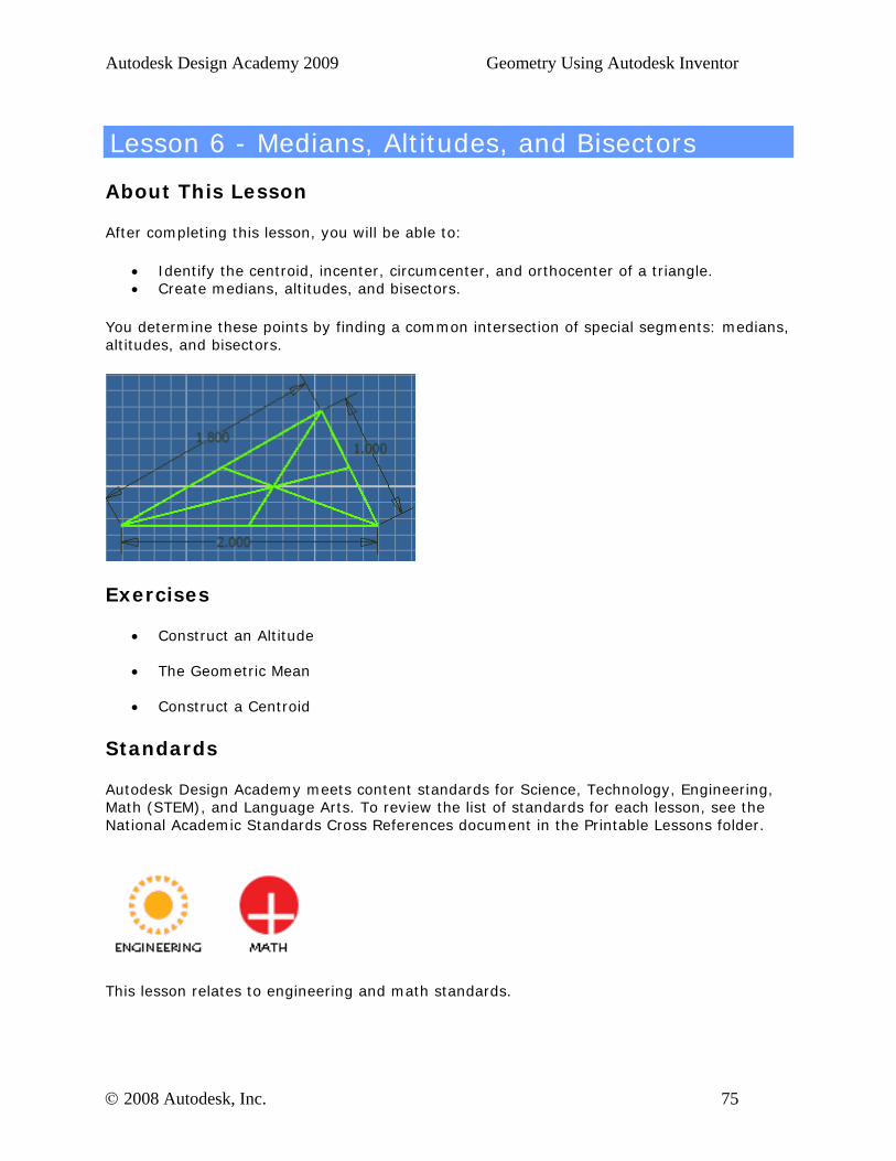
Lesson 6 - Medians, Altitudes, and Bisectors
About This Lesson
After completing this lesson, you will be able to:
• Identify the centroid, incenter, circumcenter, and orthocenter of a triangle. • Create medians, altitudes, and bisectors.
You determine these points by finding a common intersection of special segments: medians, altitudes, and bisectors.
Exercises
• Construct an Altitude
• The Geometric Mean
• Construct a Centroid
Standards
Autodesk Design Academy meets content standards for Science, Technology, Engineering, Math (STEM), and Language Arts. To review the list of standards for each lesson, see the National Academic Standards Cross References document in the Printable Lessons folder.
This lesson relates to engineering and math standards.
© 2008 Autodesk, Inc. 75
Autodesk Design Academy 2009 Geometry Using Autodesk Inventor
Key Terms
altitude concurrent inscribe similar triangles
bisect geometric mean perpendicular bisector supplementary
circumscribe hypotenuse point of tangency vertex
Lesson Plan
1. Review Properties of Triangles. (Demonstration) 2. Review Properties of Medians and Altitudes. (Demonstration) 3. Complete Exercise 1: Construct an Altitude 4. Complete Exercise 2: The Geometric Mean 5. Complete Exercise 3: Construct a Centroid 6. Evaluate Students. (Evaluation)
© 2008 Autodesk, Inc. 76
Autodesk Design Academy 2009 Geometry Using Autodesk Inventor
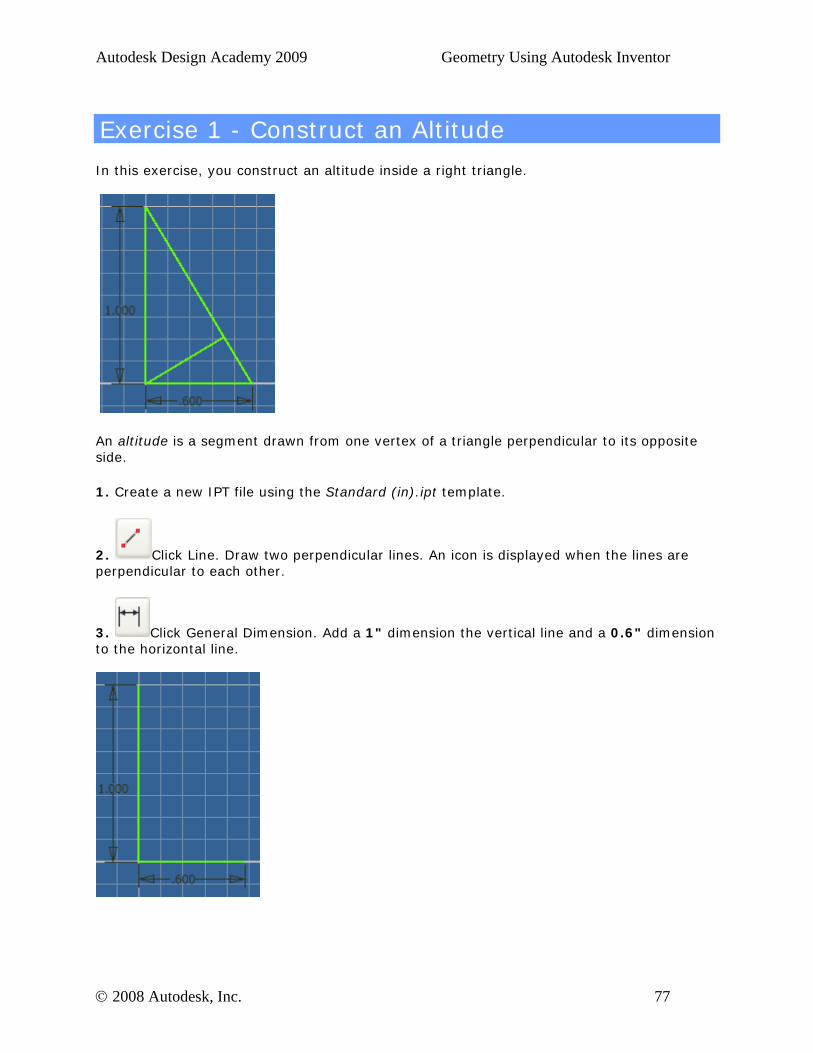
Exercise 1 - Construct an Altitude
In this exercise, you construct an altitude inside a right triangle.
An altitude is a segment drawn from one vertex of a triangle perpendicular to its opposite side.
1. Create a new IPT file using the Standard (in).ipt template.
2. Click Line. Draw two perpendicular lines. An icon is displayed when the lines are perpendicular to each other.
3. Click General Dimension. Add a 1" dimension the vertical line and a 0.6" dimension to the horizontal line.
© 2008 Autodesk, Inc. 77

Autodesk Design Academy 2009 Geometry Using Autodesk Inventor
4. Click Line. Draw a line to close the triangle.
5. From the right angle vertex, draw a line perpendicular to the hypotenuse.
6. Keep this file open for the next exercise. In this exercise, you constructed an altitude inside a right triangle.
© 2008 Autodesk, Inc. 78
Autodesk Design Academy 2009 Geometry Using Autodesk Inventor
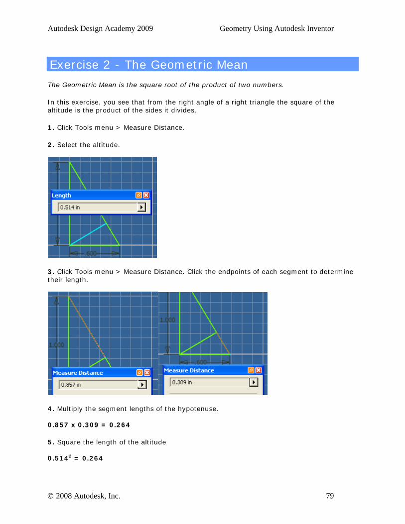
Exercise 2 - The Geometric Mean
The Geometric Mean is the square root of the product of two numbers.
In this exercise, you see that from the right angle of a right triangle the square of the altitude is the product of the sides it divides.
1. Click Tools menu > Measure Distance.
2. Select the altitude.
3. Click Tools menu > Measure Distance. Click the endpoints of each segment to determine their length.
4. Multiply the segment lengths of the hypotenuse. 0.857 x 0.309 = 0.264
5. Square the length of the altitude 0.5142 = 0.264
© 2008 Autodesk, Inc. 79

Autodesk Design Academy 2009 Geometry Using Autodesk Inventor
6. Click Return.
7. Save the file as geomean1.ipt. In this exercise, you learned that from the right angle of a right triangle the square of the altitude is the product of the sides it divides.
© 2008 Autodesk, Inc. 80
Autodesk Design Academy 2009 Geometry Using Autodesk Inventor
Exercise 3 - Construct a Centroid
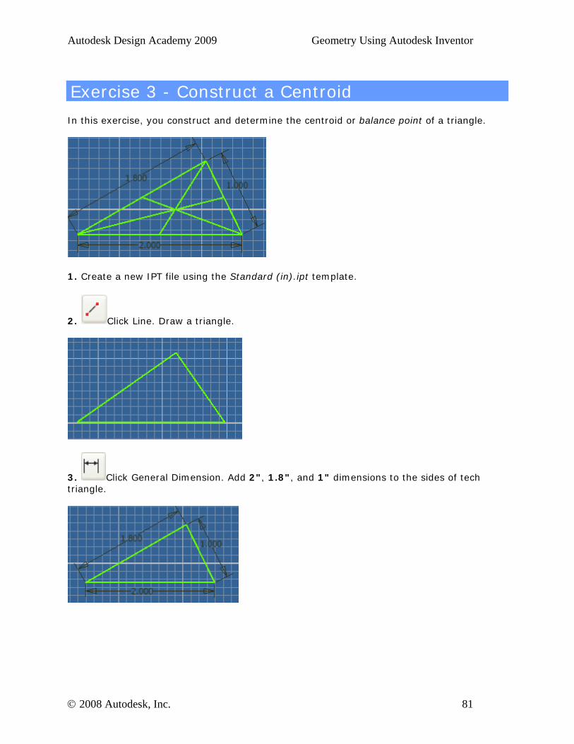
In this exercise, you construct and determine the centroid or balance point of a triangle.
1. Create a new IPT file using the Standard (in).ipt template.
2. Click Line. Draw a triangle.
3. Click General Dimension. Add 2", 1.8", and 1" dimensions to the sides of tech triangle.
© 2008 Autodesk, Inc. 81
Autodesk Design Academy 2009 Geometry Using Autodesk Inventor
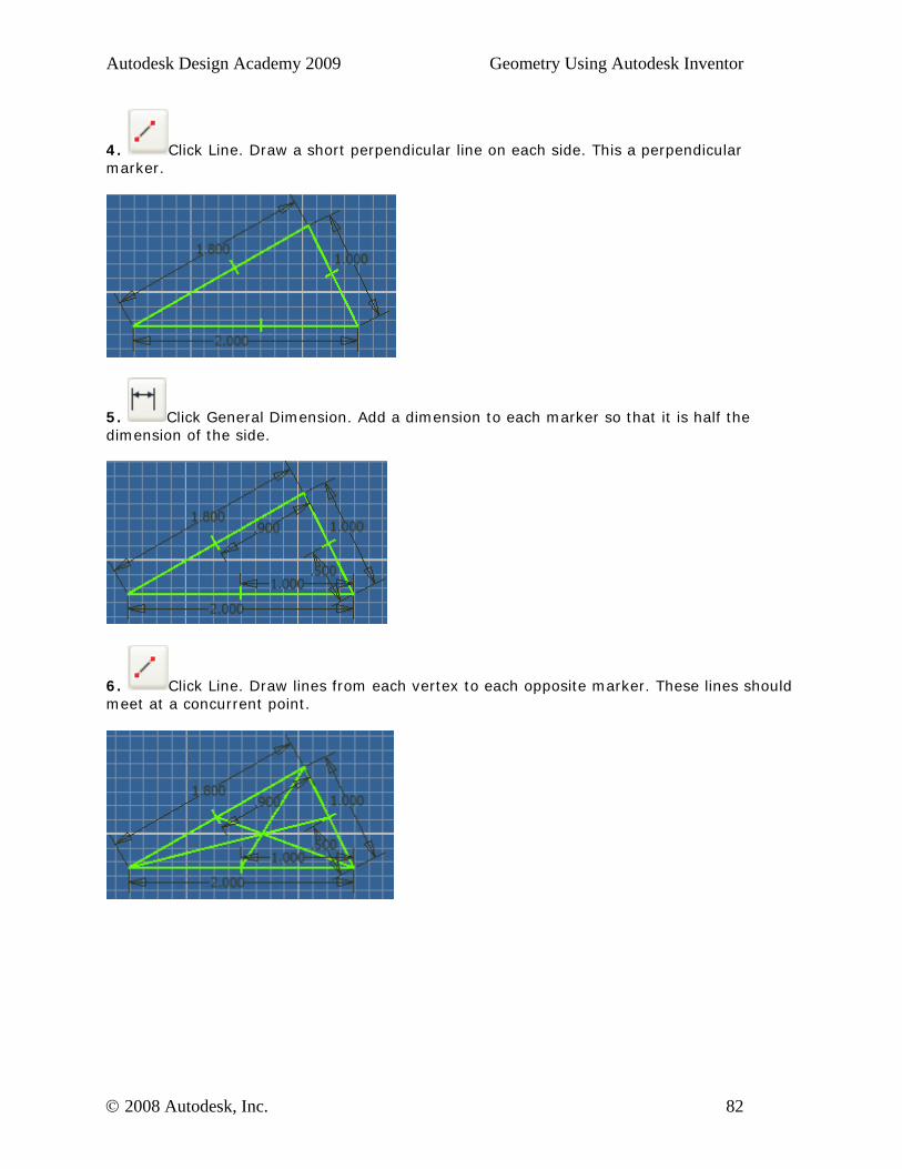
4. Click Line. Draw a short perpendicular line on each side. This a perpendicular marker.
5. Click General Dimension. Add a dimension to each marker so that it is half the dimension of the side.
6. Click Line. Draw lines from each vertex to each opposite marker. These lines should meet at a concurrent point.
© 2008 Autodesk, Inc. 82
Autodesk Design Academy 2009 Geometry Using Autodesk Inventor
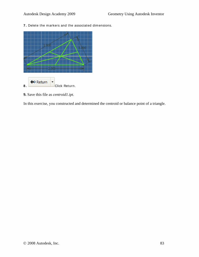
7. Delete the markers and the associated dimensions.
8. Click Return.
9. Save this file as centroid1.ipt. In this exercise, you constructed and determined the centroid or balance point of a triangle.
© 2008 Autodesk, Inc. 83


![3dsmaxdesign 2010 Using Autodesk Revit Files00[1]](https://img.pdfslide.net/doc/110x75/577d281e1a28ab4e1ea53829/3dsmaxdesign-2010-using-autodesk-revit-files001.jpg)