Embed Size (px)
DESCRIPTION
Getting started
Citation preview

Getting Started with EdgeCAM September 2007 1
Contents
Introduction .......................................................................................... 3 About this Guide...................................................................................3
Other Resources.................................................................................... 4 What is EdgeCAM?................................................................................5 Supporting Applications.........................................................................6
Installing EdgeCAM ............................................................................... 7 Fitting the security key..........................................................................7 Running EdgeCAM without a Security Key................................................7 Installing EdgeCAM...............................................................................8 If the EdgeCAM CD doesn't Autorun........................................................8 What else can I Install? .........................................................................9
Preparing EdgeCAM ............................................................................. 10 Switching to Student Edition Mode........................................................10 Starting EdgeCAM...............................................................................11 Registering EdgeCAM ..........................................................................11 The EdgeCAM User Interface................................................................12
Customising the User Interface........................................................... 13 Checking the Defaults File ...................................................................14
The Milling Exercise............................................................................. 15 Loading the CAD model .......................................................................16 Selecting the Isometric View................................................................17 Zooming In and Out............................................................................17 Creating the Stock..............................................................................18

2 September 2007 Getting Started with EdgeCAM
Using Undo ........................................................................................19 Showing Translucent Stock ..................................................................19 Finding the Features ...........................................................................20 Saving and Opening your Work ............................................................21 Specifying the ToolStore Database........................................................22 Specifying the Material ........................................................................23 Creating the Machining Sequence .........................................................24 Drilling the Hole .................................................................................25 Roughing the Part...............................................................................26 Rest Roughing the Part........................................................................28 Machining the Flat Lands .....................................................................29 Profiling the Inner Profile (Upper Boss)..................................................30 Profiling the Outer Profile (Lower Boss) .................................................32 Profiling the Pockets ...........................................................................33 Simulating the Machining ....................................................................34 Generating CNC Code .........................................................................36 Exercise Summary..............................................................................37
Creating a Code Generator Exercise .................................................... 38 Starting the Code Wizard.....................................................................38 Opening the Template.........................................................................38 Working through the Screens...............................................................40 Reviewing the Settings........................................................................40 Saving the Configuration .....................................................................41 Compiling ..........................................................................................41 Using the Code Generator....................................................................41

Getting Started with EdgeCAM September 2007 3
Introduction About this Guide
In this guide you work through a series of exercises that teach you some of the
basics of using EdgeCAM and EdgeCAM Solid Machinist. You become familiar with the user interface and some of the EdgeCAM concepts.
The guide starts with some overview information and a basic installation procedure. This is followed by some preparation of EdgeCAM for the exercises.
You then work through the complete process of producing toolpaths for
machining a part supplied as a solid model.
Please note that:
• In the exercises you use the intelligence of EdgeCAM to quickly produce results. You see how EdgeCAM speeds up your work by automatically setting
many of the machining details for you. As your knowledge of EdgeCAM increases you will learn how you can also take more detailed control of your machining, if necessary.
• As a general introduction to the EdgeCAM software the guide is not a substitute for a formal instructor-led training course.
• The guide assumes that you are familiar with a PC and Microsoft Windows. Some experience with CAD/CAM methods and terminology would be beneficial, but not essential.
• The guide is for use with EdgeCAM version 12.00 and above.
4 September 2007 Getting Started with EdgeCAM
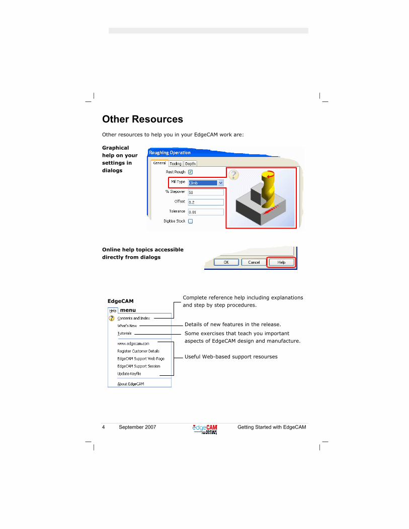
Other Resources Other resources to help you in your EdgeCAM work are:
Graphical help on your settings in
dialogs
Online help topics accessible
directly from dialogs
Complete reference help including explanations and step by step procedures.
EdgeCAM
Some exercises that teach you important aspects of EdgeCAM design and manufacture.
Useful Web-based support resourses
menu
Details of new features in the release.
Getting Started with EdgeCAM September 2007 5
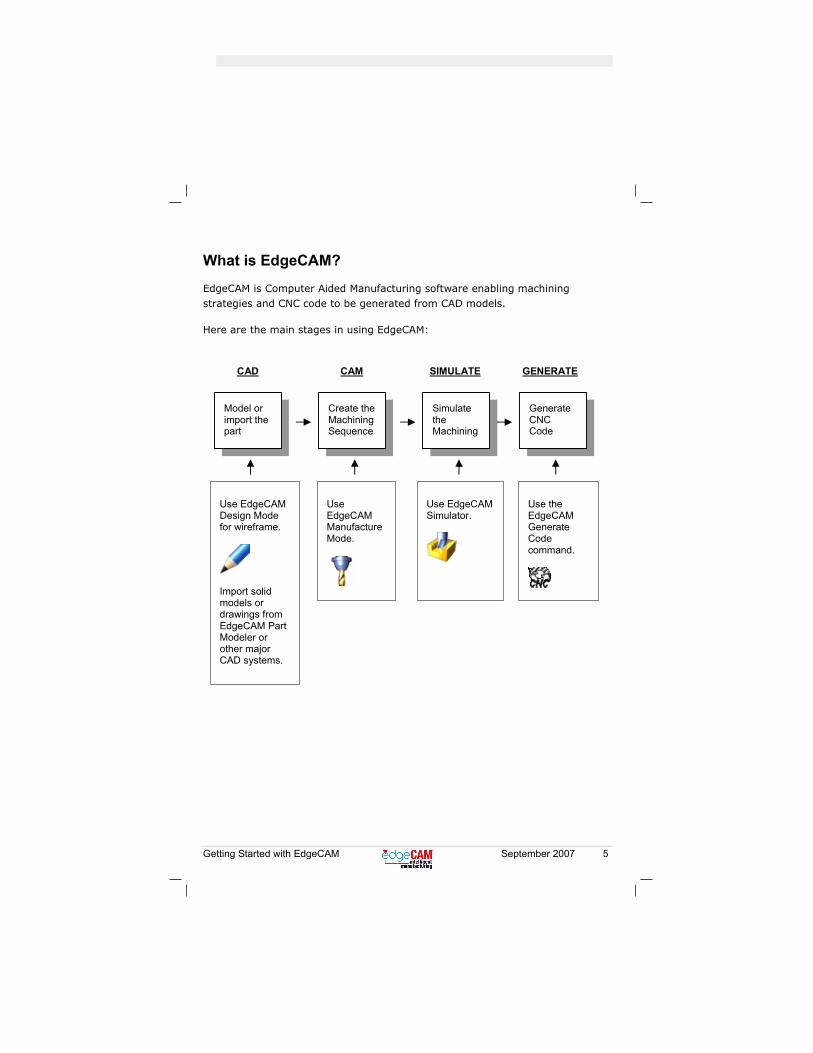
Model or import the part
Create the Machining Sequence
Simulate the Machining
Generate CNC Code
Use EdgeCAM Design Mode for wireframe.
Import solid models or drawings from EdgeCAM Part Modeler or other major CAD systems.
Use EdgeCAM Manufacture Mode.
Use EdgeCAM Simulator.
Use the EdgeCAM Generate Code command.
CAD CAM SIMULATE GENERATE
What is EdgeCAM?
EdgeCAM is Computer Aided Manufacturing software enabling machining strategies and CNC code to be generated from CAD models.
Here are the main stages in using EdgeCAM:
6 September 2007 Getting Started with EdgeCAM
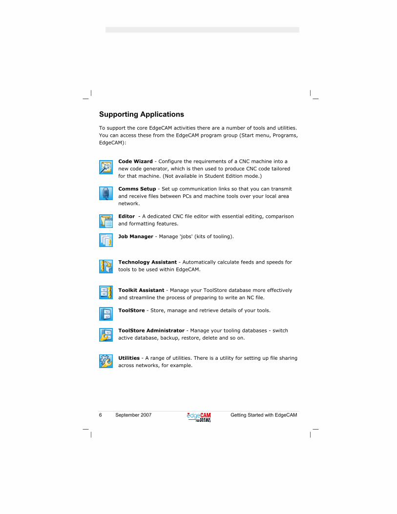
Supporting Applications
To support the core EdgeCAM activities there are a number of tools and utilities.
You can access these from the EdgeCAM program group (Start menu, Programs, EdgeCAM):
Code Wizard - Configure the requirements of a CNC machine into a new code generator, which is then used to produce CNC code tailored for that machine. (Not available in Student Edition mode.)
Comms Setup - Set up communication links so that you can transmit and receive files between PCs and machine tools over your local area network.
Editor - A dedicated CNC file editor with essential editing, comparison and formatting features.
Job Manager - Manage 'jobs' (kits of tooling).
Technology Assistant - Automatically calculate feeds and speeds for tools to be used within EdgeCAM.
Toolkit Assistant - Manage your ToolStore database more effectively
and streamline the process of preparing to write an NC file.
ToolStore - Store, manage and retrieve details of your tools.
ToolStore Administrator - Manage your tooling databases - switch active database, backup, restore, delete and so on.
Utilities - A range of utilities. There is a utility for setting up file sharing across networks, for example.
Getting Started with EdgeCAM September 2007 7
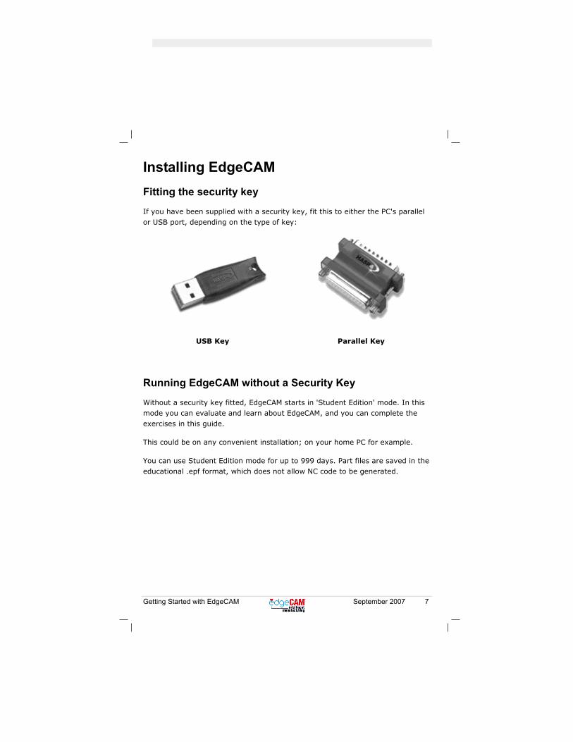
Installing EdgeCAM Fitting the security key
If you have been supplied with a security key, fit this to either the PC's parallel
or USB port, depending on the type of key:
USB Key
Parallel Key
Running EdgeCAM without a Security Key
Without a security key fitted, EdgeCAM starts in 'Student Edition' mode. In this mode you can evaluate and learn about EdgeCAM, and you can complete the exercises in this guide.
This could be on any convenient installation; on your home PC for example.
You can use Student Edition mode for up to 999 days. Part files are saved in the educational .epf format, which does not allow NC code to be generated.

8 September 2007 Getting Started with EdgeCAM
Installing EdgeCAM
On inserting the CD this screen appears:
Click Install EdgeCAM and follow the on-screen instructions.
For a quick and easy installation that is ready for the exercises, at the prompts accept all the default choices. At the Select Components prompt choose Typical.
If the EdgeCAM CD doesn't Autorun If the opening screen doesn't appear when you insert the installation CD you need to run the setup executable. You can open Windows explorer, then navigate to and open:
CD Rom drive\EdgeCAM\Setup.exe
For example if 'D:' is your CD Rom drive you would open:
D:\EdgeCAM\Setup.exe
(Note that you do not use the setup.exe in the root folder of the CD.)

Getting Started with EdgeCAM September 2007 9
What else can I Install?
You have already installed the necessary software for the exercises.
For your information, here are some other software options:
Install If
EdgeCAM CAD Link You want to be able to launch
EdgeCAM from your CAD system. You can install links in:
• Autodesk Inventor
• SolidWorks
• Solid Edge
Note that EdgeCAM Part Modeler automatically includes a link to EdgeCAM.
EdgeCAM Part Modeler You want to install EdgeCAM Part Modeler; a powerful solids-based CAD
package.

10 September 2007 Getting Started with EdgeCAM
Preparing EdgeCAM Switching to Student Edition Mode
So that you can complete the exercises no matter what EdgeCAM licence you
have, you use EdgeCAM in Student Edition mode.
If you do not have a security key fitted EdgeCAM automatically starts in this mode (if you are learning on an installation at your home for example).
If you do have a security key fitted, before starting EdgeCAM:
• Find the Windows' Notification Area (usually at the bottom-right of the screen, where the time is displayed).
• In this area right-click the EdgeCLS icon and in the menu that opens click Run
Student Edition to enable it.
The next time EdgeCAM starts it will be in Student Edition mode.
Switching back to Normal Licenced Mode
You might need to change back to normal licenced mode in between exercise sessions. To do this close EdgeCAM (you can use the Close button in the top right corner of the EdgeCAM window - see page 21) and repeat the step above - clicking 'Run Student Edition' again disables it, and EdgeCAM will next start in
the normal licenced mode.
Getting Started with EdgeCAM September 2007 11
Starting EdgeCAM
In a standard installation:
• Click the EdgeCAM icon on your desktop.
• Alternatively click the Start button, then All Programs, then EdgeCAM then
EdgeCAM.
• You see a message dialog stating you are in Student Edition Mode. Confirm in the dialog to continue.
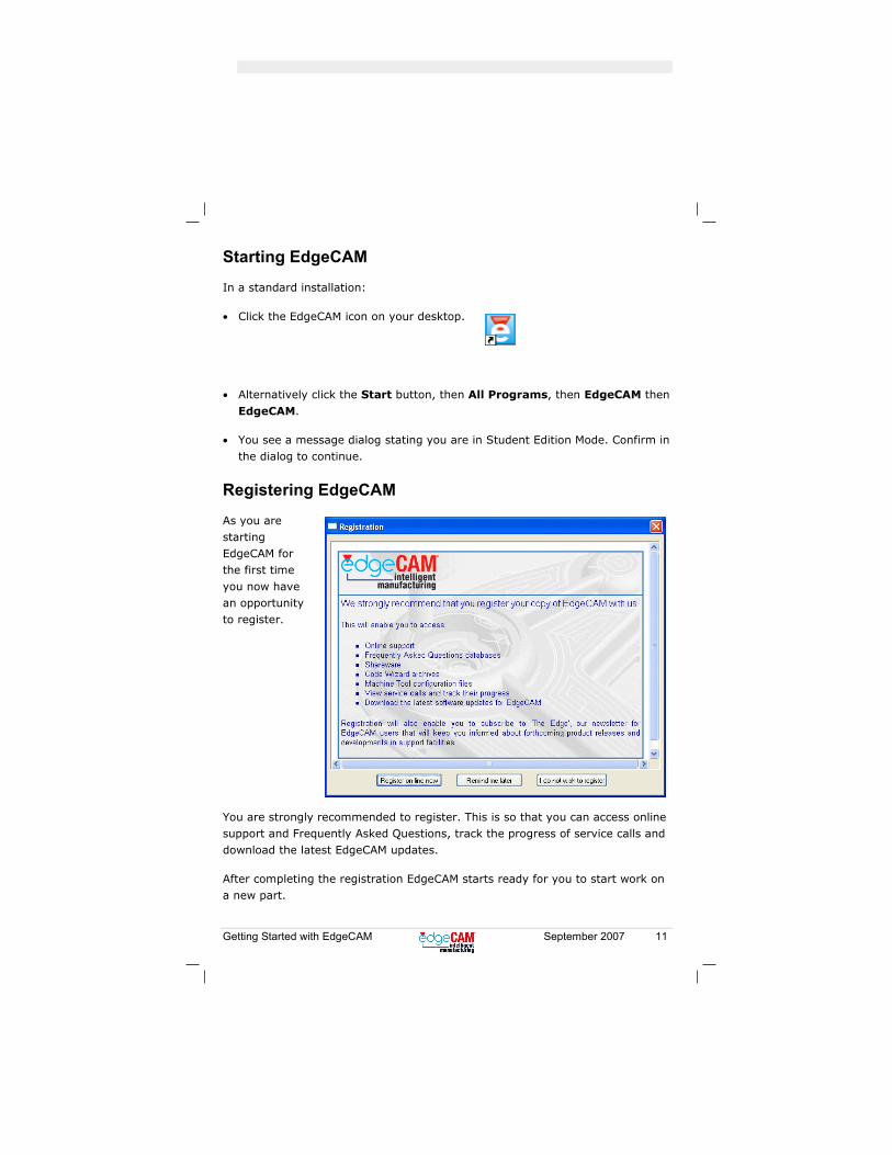
Registering EdgeCAM
As you are starting EdgeCAM for the first time
you now have an opportunity to register.
You are strongly recommended to register. This is so that you can access online support and Frequently Asked Questions, track the progress of service calls and download the latest EdgeCAM updates.
After completing the registration EdgeCAM starts ready for you to start work on a new part.
12 September 2007 Getting Started with EdgeCAM
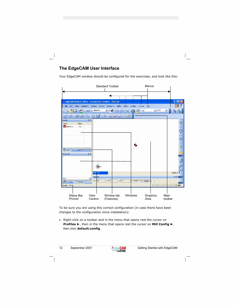
Menus Standard Toolbar
Status Bar Prompt
View Caption
Window tab (Features)
Windows Graphics Area
Main toolbar
The EdgeCAM User Interface
Your EdgeCAM window should be configured for the exercises, and look like this:
To be sure you are using this correct configuration (in case there have been
changes to the configuration since installation):
• Right-click on a toolbar and in the menu that opens rest the cursor on Profiles ►, then in the menu that opens rest the cursor on Mill Config ►, then click default.config.
Getting Started with EdgeCAM September 2007 13
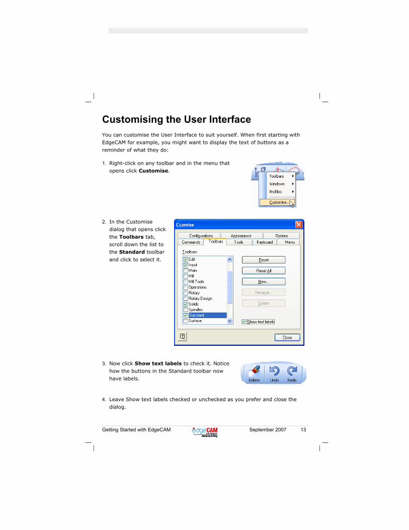
Customising the User Interface You can customise the User Interface to suit yourself. When first starting with EdgeCAM for example, you might want to display the text of buttons as a reminder of what they do:
1. Right-click on any toolbar and in the menu that
opens click Customise.
2. In the Customise dialog that opens click the Toolbars tab, scroll down the list to the Standard toolbar
and click to select it.
3. Now click Show text labels to check it. Notice how the buttons in the Standard toolbar now have labels.
4. Leave Show text labels checked or unchecked as you prefer and close the dialog.

14 September 2007 Getting Started with EdgeCAM
Checking the Defaults File
The default installation of EdgeCAM is suitable for the exercises.
To be sure you are using the correct defaults file (in case there have been changes to the defaults since installation):
1. Click the Options menu and click Select Defaults to open the Defaults dialog.
2. If the file entered in the Name box is not mill_mm.dft, click the Browse button and use the browser dialog to navigate to and open:
installation folder\Cam\Supprt\mill_mm.dft for example:
c:\Program Files\EdgeCAM\Cam\Support\mill_mm.dft
This enables the milling (XY) environment and millimetre (mm) units. (The defaults file also contains many other settings, such as the Tolerance setting.)
3. If you had to change to mill_mm.dft, and you want EdgeCAM to automatically use this file every time it starts, click in the Load on Entry box and in the list that opens click Selected File.
(Note that you do not need to re-set the defaults every time you re-open saved work, as the settings become part of the saved file.)
4. Click OK.

Getting Started with EdgeCAM September 2007 15
The Milling Exercise In the exercise you learn how to:
• Open a solid model.
• Change the view - select Isometric and zoom in and out.
• Create stock.
• Specify the stock material.
• Undo after a mistake.
• Find 'features' in the solid model, on which to base your machining.
• Save your work.
• Specify a ToolStore database.
• Create machining for the features using 'operations'. An operation is a
complete package for producing the feature, including cycles (that control the toolpath) and any necessary moves to tool change, tool changes and so on.
• Simulate your machining.
• Generate CNC code for the machining.

16 September 2007 Getting Started with EdgeCAM
Loading the CAD model
1. In the Standard toolbar (or File menu) click the Open
button.
2. In the Open dialog that appears, navigate to the folder:
installation folder\Cam\Examples\tutorial\Solid Machinist\Parasolid
For example:
C:\Program Files\EdgeCAM\Cam\Examples\tutorial\Solid Machinist\Parasolid
3. From this folder open prismatic milling.x_t.
The part opens looking like this:
Getting Started with EdgeCAM September 2007 17
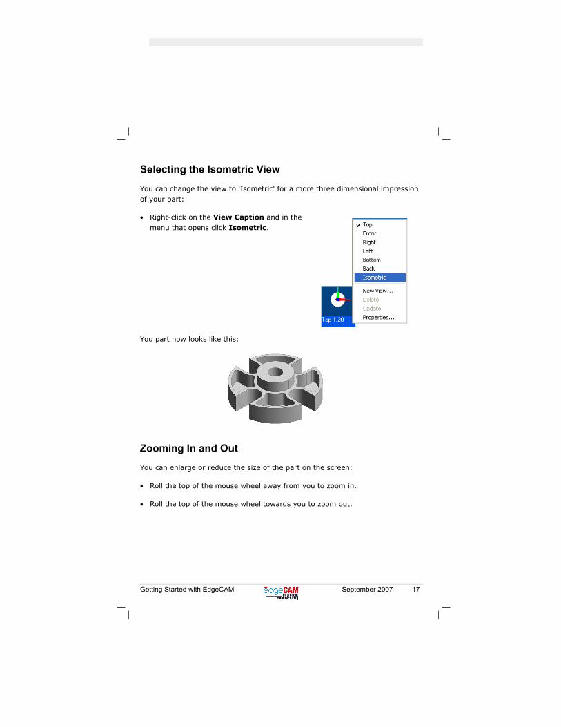
Selecting the Isometric View
You can change the view to 'Isometric' for a more three dimensional impression of your part:
• Right-click on the View Caption and in the menu that opens click Isometric.
You part now looks like this:
Zooming In and Out
You can enlarge or reduce the size of the part on the screen:
• Roll the top of the mouse wheel away from you to zoom in.
• Roll the top of the mouse wheel towards you to zoom out.
18 September 2007 Getting Started with EdgeCAM
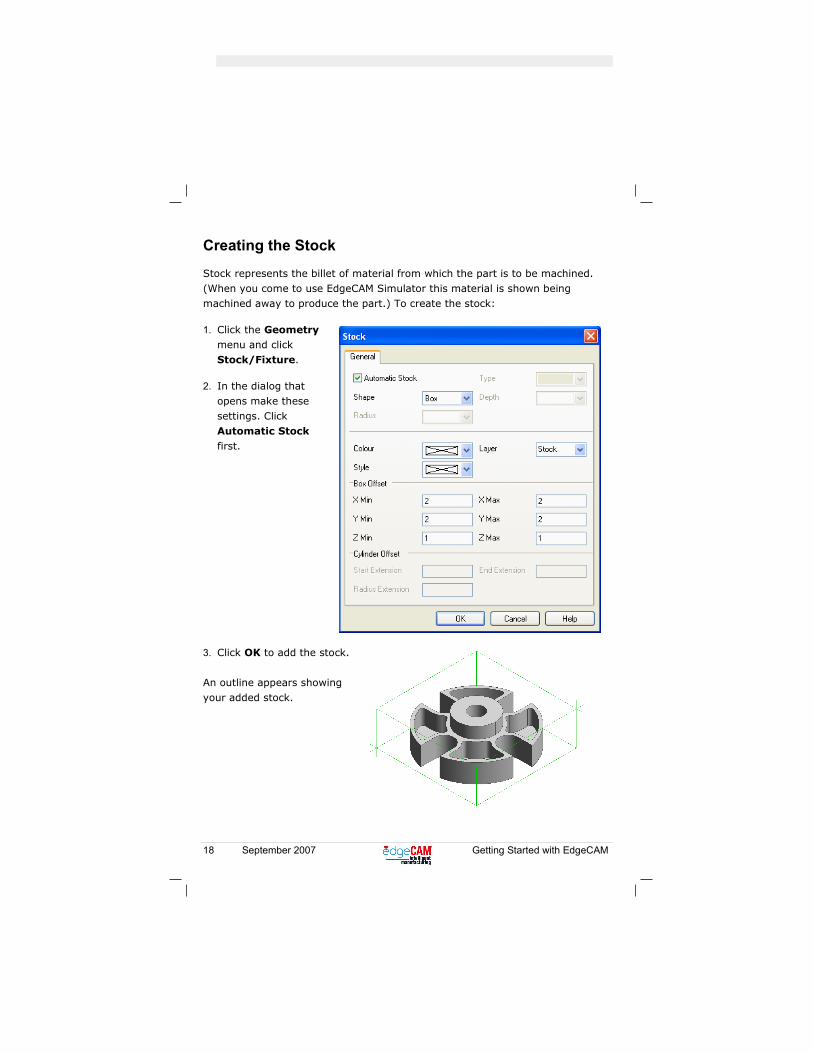
Creating the Stock
Stock represents the billet of material from which the part is to be machined. (When you come to use EdgeCAM Simulator this material is shown being machined away to produce the part.) To create the stock:
1. Click the Geometry menu and click Stock/Fixture.
2. In the dialog that opens make these settings. Click Automatic Stock first.
3. Click OK to add the stock.
An outline appears showing your added stock.

Getting Started with EdgeCAM September 2007 19
Using Undo
If you make a mistake you can cancel your last action:
1. In the Standard toolbar click the Undo button.
Your added stock disappears. You could now recreate stock with different settings, for example.
Our stock is OK however, so to 'undo the undo':
2. In the Standard toolbar click the Redo button.
Your stock re-appears.
Showing Translucent Stock
1. In the Display toolbar (to the right of the Standard toolbar) click the Toggle Stock button.
The stock display changes to 'translucent'.
2. Click the button again to switch back (to 'wireframe').
Leave the stock displayed as you prefer (stock is shown as wireframe in the
exercises).
20 September 2007 Getting Started with EdgeCAM
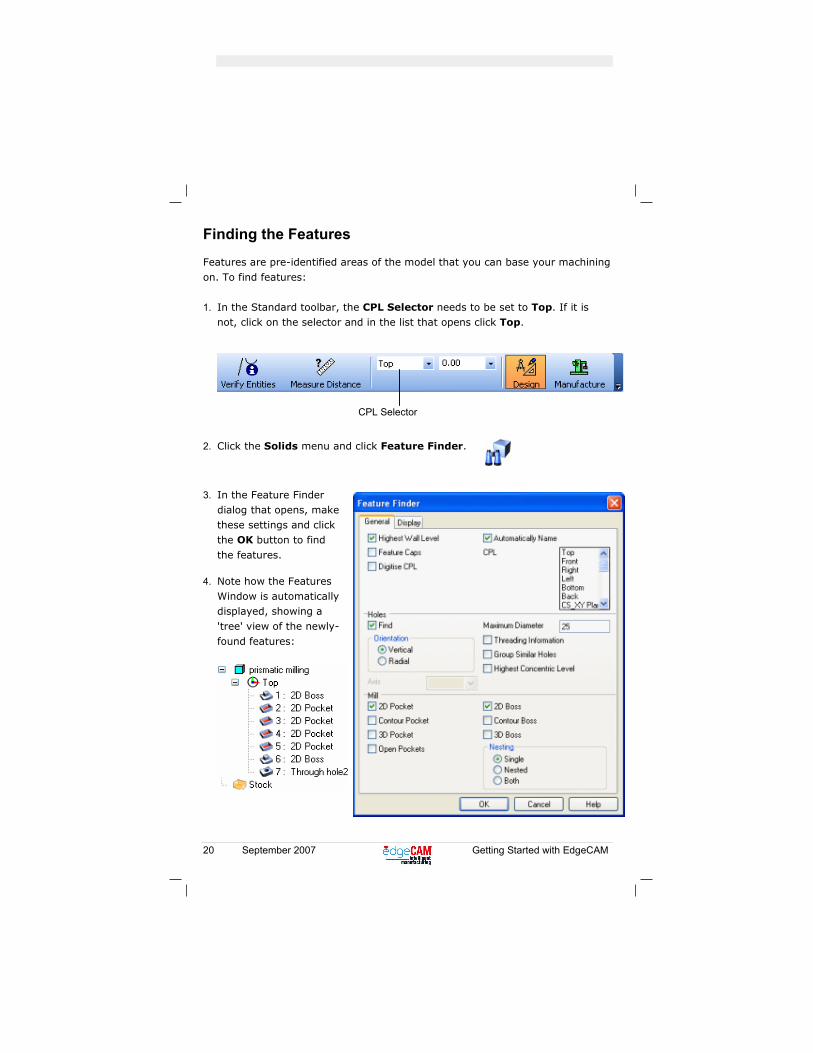
CPL Selector
Finding the Features
Features are pre-identified areas of the model that you can base your machining
on. To find features:
1. In the Standard toolbar, the CPL Selector needs to be set to Top. If it is not, click on the selector and in the list that opens click Top.
2. Click the Solids menu and click Feature Finder.
3. In the Feature Finder dialog that opens, make these settings and click the OK button to find
the features.
4. Note how the Features Window is automatically displayed, showing a 'tree' view of the newly-
found features:
Getting Started with EdgeCAM September 2007 21
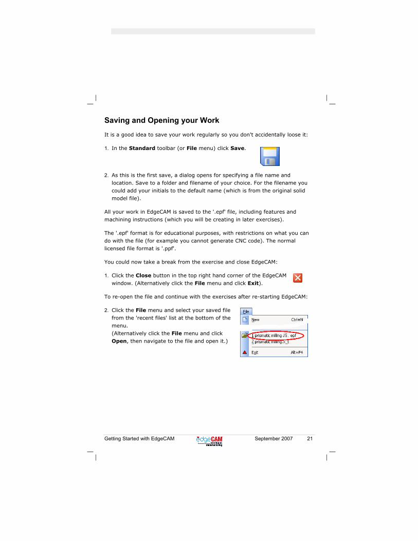
Saving and Opening your Work
It is a good idea to save your work regularly so you don't accidentally loose it:
1. In the Standard toolbar (or File menu) click Save.
2. As this is the first save, a dialog opens for specifying a file name and location. Save to a folder and filename of your choice. For the filename you
could add your initials to the default name (which is from the original solid model file).
All your work in EdgeCAM is saved to the '.epf' file, including features and machining instructions (which you will be creating in later exercises).
The '.epf' format is for educational purposes, with restrictions on what you can do with the file (for example you cannot generate CNC code). The normal licensed file format is '.ppf'.
You could now take a break from the exercise and close EdgeCAM:
1. Click the Close button in the top right hand corner of the EdgeCAM
window. (Alternatively click the File menu and click Exit).
To re-open the file and continue with the exercises after re-starting EdgeCAM:
2. Click the File menu and select your saved file from the 'recent files' list at the bottom of the
menu. (Alternatively click the File menu and click Open, then navigate to the file and open it.)
22 September 2007 Getting Started with EdgeCAM
Specifying the ToolStore Database
You will be selecting pre-defined tools from the ToolStore.
Using the ToolStore you can access tools from different databases, so you need to ensure you are using the correct example database, that is installed with EdgeCAM:
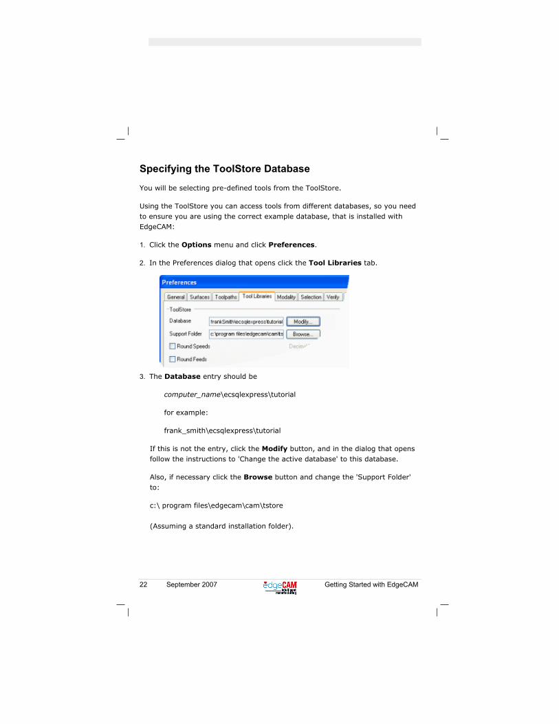
1. Click the Options menu and click Preferences.
2. In the Preferences dialog that opens click the Tool Libraries tab.
3. The Database entry should be
computer_name\ecsqlexpress\tutorial
for example:
frank_smith\ecsqlexpress\tutorial
If this is not the entry, click the Modify button, and in the dialog that opens follow the instructions to 'Change the active database' to this database.
Also, if necessary click the Browse button and change the 'Support Folder' to:
c:\ program files\edgecam\cam\tstore (Assuming a standard installation folder).
Getting Started with EdgeCAM September 2007 23
Specifying the Material
As you will be using operations, speeds and feeds are automatically calculated.
These are based on the material being machined, so you need to specify this:
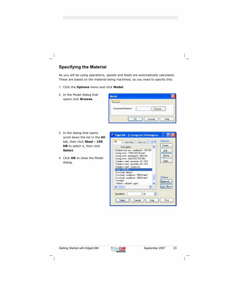
1. Click the Options menu and click Model.
2. In the Model dialog that opens click Browse.
3. In the dialog that opens scroll down the list in the All tab, then click Steel - 150 HB to select it, then click Select.
4. Click OK to close the Model dialog.
24 September 2007 Getting Started with EdgeCAM
Creating the Machining Sequence
You now start to create your machining instructions:
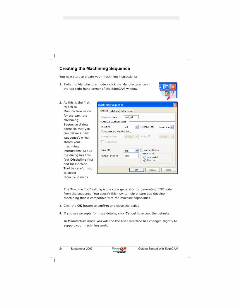
1. Switch to Manufacture mode - click the Manufacture icon in the top right hand corner of the EdgeCAM window.
2. As this is the first switch to Manufacture mode for the part, the Machining
Sequence dialog opens so that you can define a new 'sequence', which stores your machining
instructions. Set up the dialog like this (set Discipline first and for Machine Tool be careful not to select
fanuc3x-in.mcp).
The 'Machine Tool' setting is the code generator for generating CNC code from the sequence. You specify this now to help ensure you develop machining that is compatible with the machine capabilities.
3. Click the OK button to confirm and close the dialog.
4. If you see prompts for more details, click Cancel to accept the defaults.
In Manufacture mode you will find the User Interface has changed slightly to support your machining work.
Getting Started with EdgeCAM September 2007 25
Drilling the Hole
Now you drill the hole through the centre of the part:
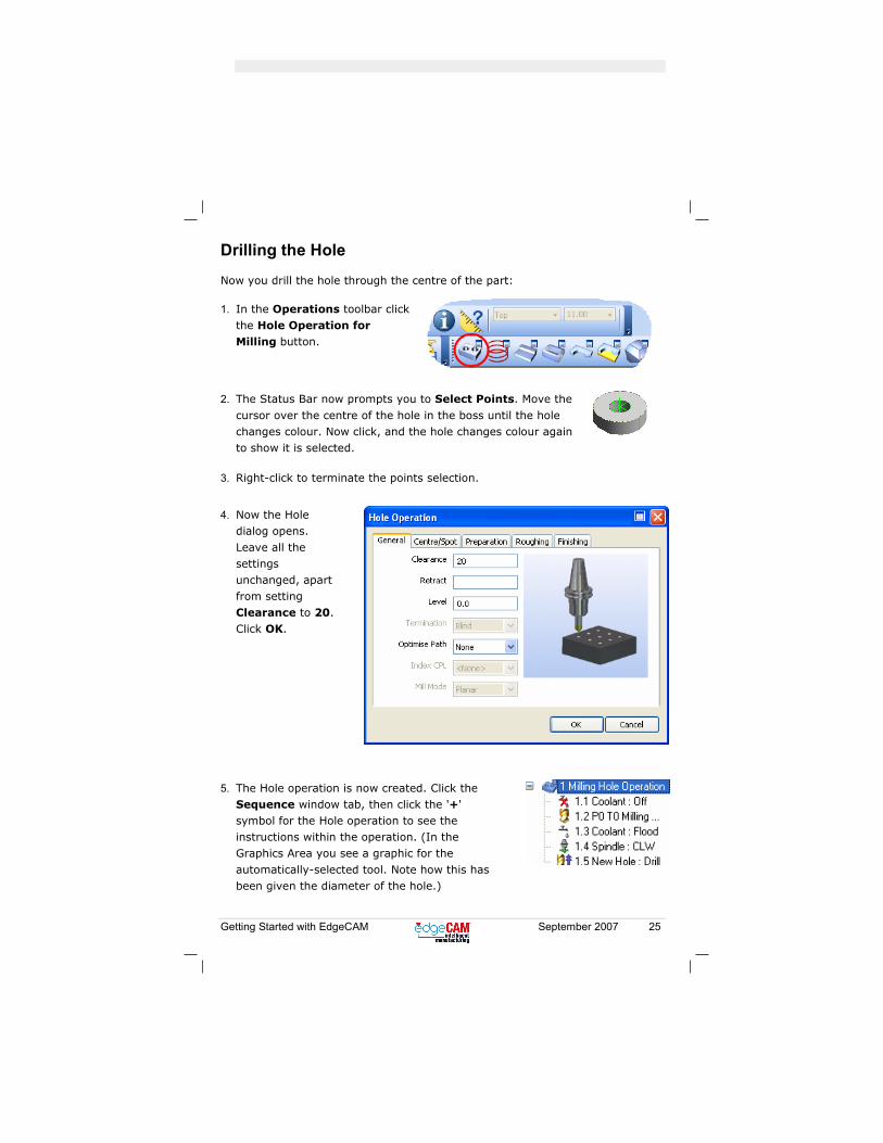
1. In the Operations toolbar click the Hole Operation for Milling button.
2. The Status Bar now prompts you to Select Points. Move the
cursor over the centre of the hole in the boss until the hole changes colour. Now click, and the hole changes colour again to show it is selected.
3. Right-click to terminate the points selection.
4. Now the Hole
dialog opens.
Leave all the settings unchanged, apart from setting Clearance to 20. Click OK.
5. The Hole operation is now created. Click the
Sequence window tab, then click the '+' symbol for the Hole operation to see the instructions within the operation. (In the Graphics Area you see a graphic for the
automatically-selected tool. Note how this has been given the diameter of the hole.)
26 September 2007 Getting Started with EdgeCAM
Roughing the Part
Now you rough the part:
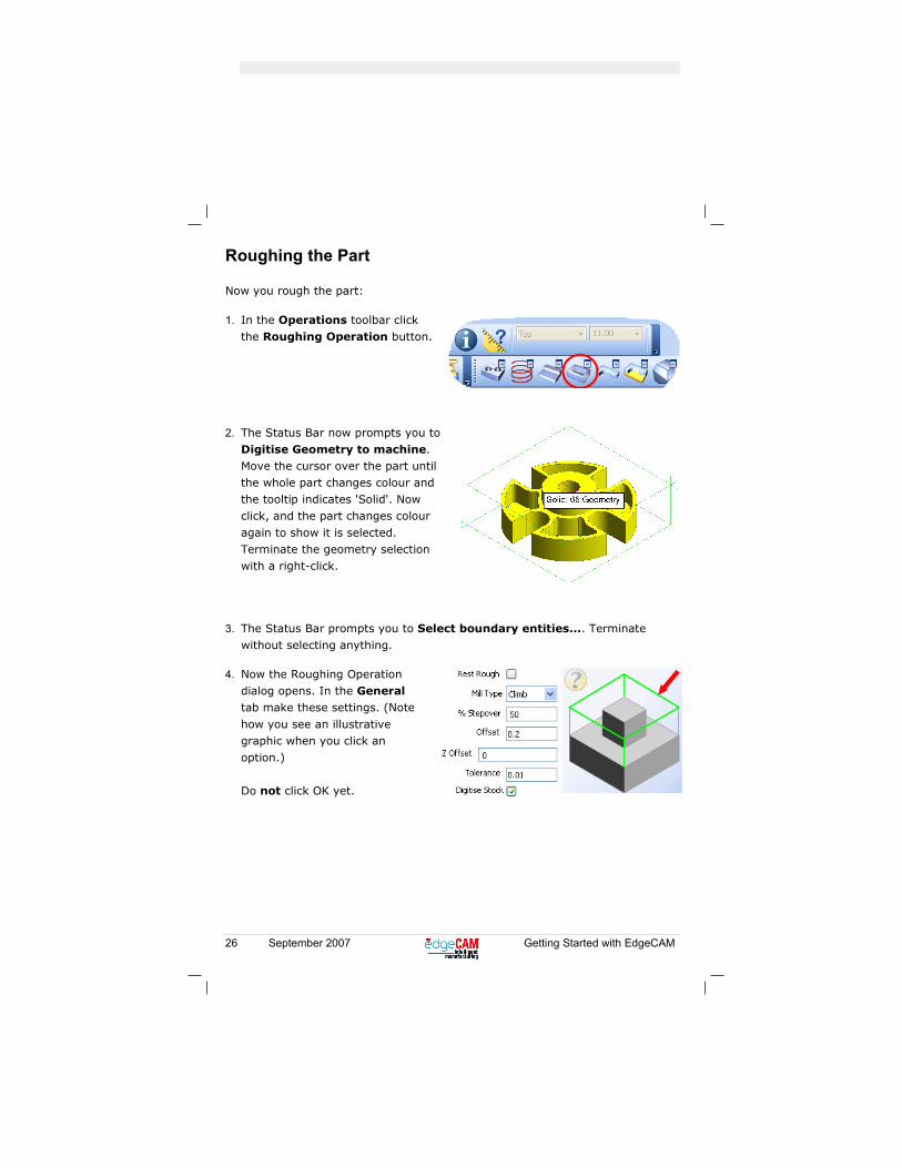
1. In the Operations toolbar click the Roughing Operation button.
2. The Status Bar now prompts you to
Digitise Geometry to machine. Move the cursor over the part until the whole part changes colour and the tooltip indicates 'Solid'. Now click, and the part changes colour
again to show it is selected. Terminate the geometry selection with a right-click.
3. The Status Bar prompts you to Select boundary entities.... Terminate without selecting anything.
4. Now the Roughing Operation dialog opens. In the General tab make these settings. (Note
how you see an illustrative graphic when you click an option.) Do not click OK yet.

Getting Started with EdgeCAM September 2007 27
5. Click the Tooling tab and in this tab click Find to open the ToolStore. In the ToolStore's tooling list scroll to 14 mm Endmill - 4 Flute 13A F30M and click to select it. Click the Select button.
6. Click the Depth tab and set Clearance to 5, Level to 0, Depth to 0 and Cut Increment to 2. Click OK to close the dialog.
7. The Status Bar now prompts you to Digitise Stock. Rest the cursor on one of the lines comprising the top
profile of the stock. The line changes colour and the tooltip indicates 'Stock'. Double-click to select the whole top profile. Then right-click to terminate the stock selection.
The Roughing operation is now created. The toolpath is displayed on the part.
8. Click the Sequence window tab. Now click
the '+' symbol for the Roughing operation
to see the instructions within the operation.

28 September 2007 Getting Started with EdgeCAM
Rest Roughing the Part
In the previous roughing operation the tool was too large to remove all the material (the tool could not fit into the pockets, for example). You now 'rest rough' with a smaller tool to remove this material.
To do this repeat the previous Roughing operation, but with slight changes. Here is a summary, with the changes marked '*':
1. In the Operations toolbar click Roughing Operation.
2. Select the whole solid.
3. Select no boundaries.
4. In the Roughing Dialog, General tab, set Rest Rough to checked *, set Offset to 0.2, set Digitise Stock to unchecked * (you can leave the other settings as they are).
5. Click the Tooling tab and from the ToolStore select the tool 6 mm Endmill - long series* (you can leave the other settings as they are).
6. Click the Depth tab and set Clearance to 5, Level to 0, Depth to 0 and Cut Increment to 2. Click OK to close the dialog and generate the operation (there will be no prompt for stock).
7. In the Sequence window rest the cursor on 3
Roughing Operation (that you have just created). Notice how the toolpath for the operation becomes highlighted.
Getting Started with EdgeCAM September 2007 29
Machining the Flat Lands
You now use a finishing tool on the flat areas, removing the material left by the
0.2 offset in the previous Roughing operations:
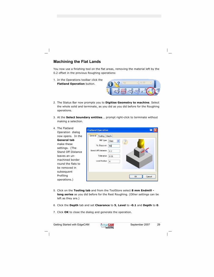
1. In the Operations toolbar click the Flatland Operation button.
2. The Status Bar now prompts you to Digitise Geometry to machine. Select the whole solid and terminate, as you did as you did before for the Roughing operations.
3. At the Select boundary entities... prompt right-click to terminate without
making a selection.
4. The Flatland Operation dialog now opens. In the General tab
make these settings. (The Stand Off Distance leaves an un-machined border round the flats to
be removed in subsequent Profiling operations.)
5. Click on the Tooling tab and from the ToolStore select 8 mm Endmill - long series as you did before for the Rest Roughing. (Other settings can be left as they are.)
6. Click the Depth tab and set Clearance to 5, Level to -0.1 and Depth to 0.
7. Click OK to close the dialog and generate the operation.
30 September 2007 Getting Started with EdgeCAM
Profiling the Inner Profile (Upper Boss)
Now you profile finish the upper central boss:
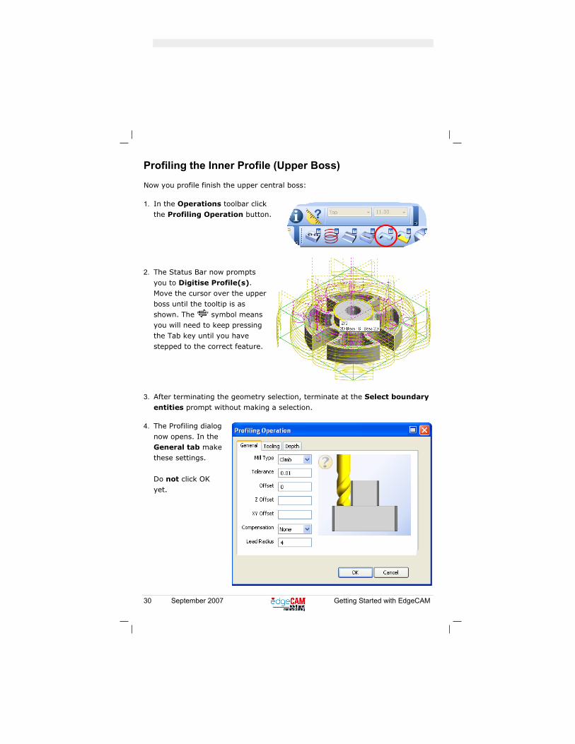
1. In the Operations toolbar click the Profiling Operation button.
2. The Status Bar now prompts
you to Digitise Profile(s). Move the cursor over the upper boss until the tooltip is as shown. The ' ' symbol means you will need to keep pressing the Tab key until you have
stepped to the correct feature.
3. After terminating the geometry selection, terminate at the Select boundary
entities prompt without making a selection.
4. The Profiling dialog now opens. In the General tab make these settings.
Do not click OK yet.
Getting Started with EdgeCAM September 2007 31
5. Click the Tooling tab and from the ToolStore select the 5 mm diameter SSM-ZX-2 Flute-5 (other settings can be left as they are).
6. Click the Depth tab and set Clearance to 5, Level to 0, Depth to 0, Cut Increment to 2 and Cusp Height to 0.
7. Click OK to close the dialog and generate the toolpath.
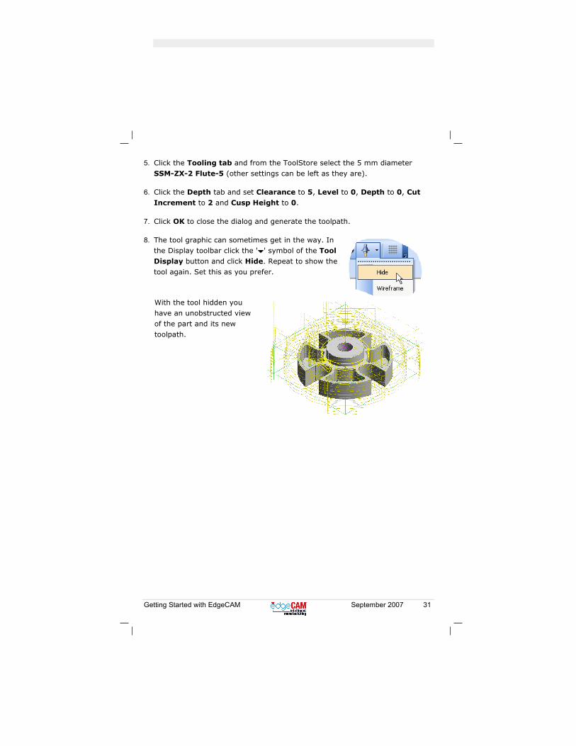
8. The tool graphic can sometimes get in the way. In the Display toolbar click the ' ' symbol of the Tool Display button and click Hide. Repeat to show the
tool again. Set this as you prefer.
With the tool hidden you have an unobstructed view of the part and its new toolpath.

32 September 2007 Getting Started with EdgeCAM
Profiling the Outer Profile (Lower Boss)
Now you machine the outer perimeter of the part.
To do this repeat the previous Profiling operation, but with slight changes. Here is a summary, with the changes marked '*':
1. In the Operations toolbar click Profiling Operation.
2. For the profile select the lower 2D Boss*.
3. Select no boundaries.
4. In the Profiling dialog, General tab, set: Offset to 0 and Lead Radius to 4. (Other settings can be left as they are).
5. In the Profiling dialog Tooling tab open the ToolStore and select the 5 mm diameter SSM-ZX-2 Flute-5. (Other settings can be left as they are.)
6. In the Profiling dialog Depth tab, set: Clearance to 5, Level to 0, Depth to 0, Cut Increment to 2, Cusp Height to 0. Click OK to close the dialog and generate the operation.
7. Rest the cursor on the new operation to highlight its toolpath.
Getting Started with EdgeCAM September 2007 33
Profiling the Pockets
You now start to machine the pockets.
To do this repeat the previous Profiling operations, but with slight changes. Here is a summary, with the changes marked '*':
1. In the Operations toolbar click Profiling Operation.
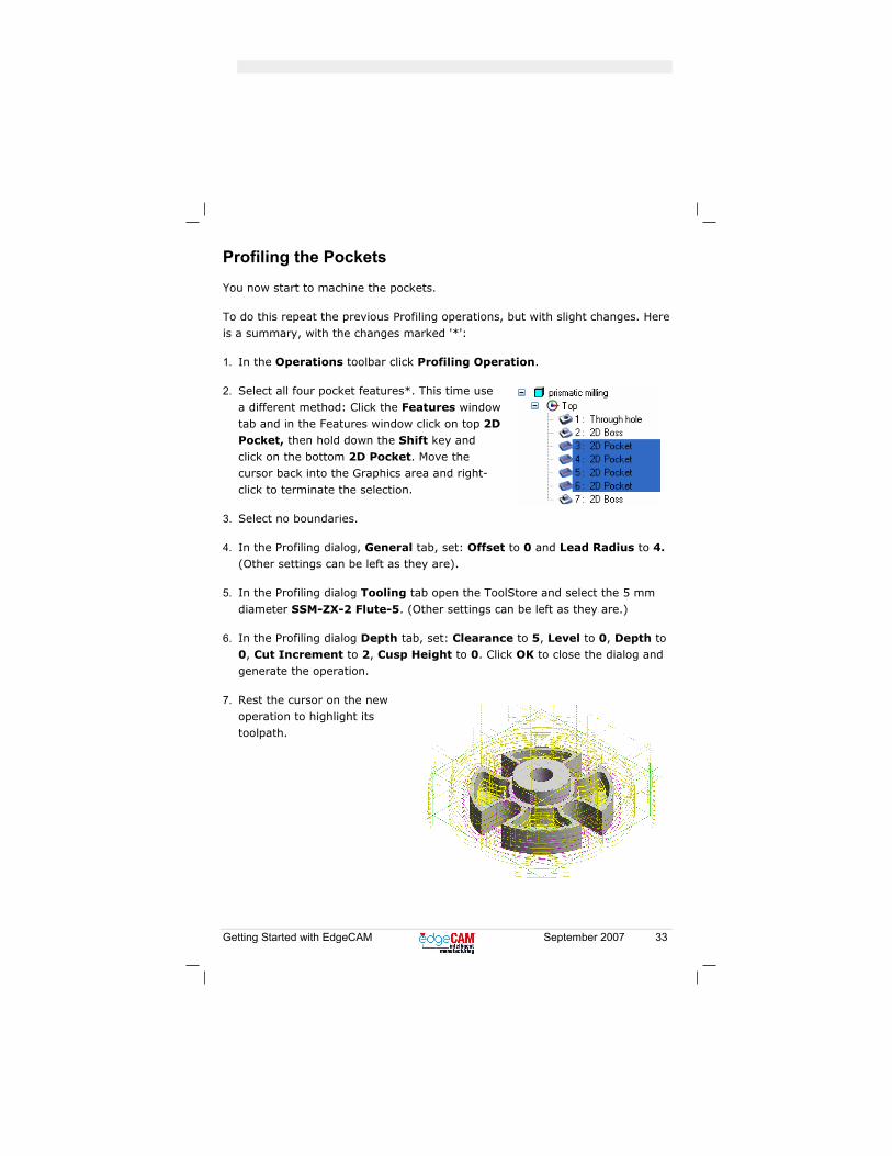
2. Select all four pocket features*. This time use
a different method: Click the Features window tab and in the Features window click on top 2D Pocket, then hold down the Shift key and click on the bottom 2D Pocket. Move the cursor back into the Graphics area and right-click to terminate the selection.
3. Select no boundaries.
4. In the Profiling dialog, General tab, set: Offset to 0 and Lead Radius to 4. (Other settings can be left as they are).
5. In the Profiling dialog Tooling tab open the ToolStore and select the 5 mm
diameter SSM-ZX-2 Flute-5. (Other settings can be left as they are.)
6. In the Profiling dialog Depth tab, set: Clearance to 5, Level to 0, Depth to 0, Cut Increment to 2, Cusp Height to 0. Click OK to close the dialog and generate the operation.
7. Rest the cursor on the new operation to highlight its toolpath.

34 September 2007 Getting Started with EdgeCAM
Simulating the Machining
You have now created the machining, so you can simulate it. Simulating gives
you a visual 'confidence check' of your machining. You can check, for example, that you have not forgotten to machine a feature, and that there are no tool collisions.
You will be quickly running through the main features of the Simulator, there are many more you will use with experience.
• In the Main toolbar underneath the Standard toolbar (or in the View menu) click Simulate Machining.
You see the Simulator window containing your un-machined stock:

Getting Started with EdgeCAM September 2007 35
• Click the button for starting the simulation.
You see your part being machined out of
the stock.
• As the simulation continues, click the Speed Control button.
• In the Speed Control that appears, drag
the slider to the left and right to control the speed of the simulation.
• Use these buttons to control the simulation at any time:
Play/Resume
Shuttle
Pause
To Start
To End
36 September 2007 Getting Started with EdgeCAM
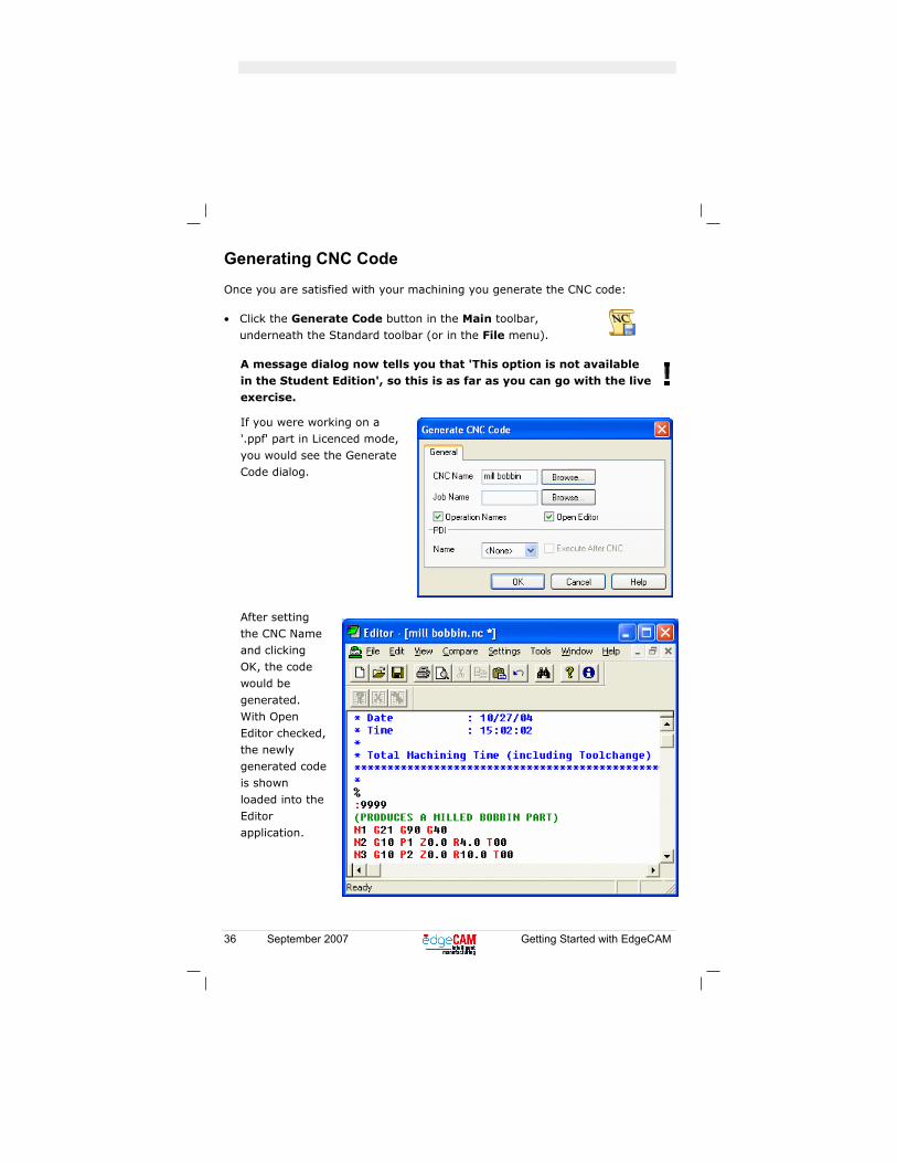
Generating CNC Code
Once you are satisfied with your machining you generate the CNC code:
• Click the Generate Code button in the Main toolbar, underneath the Standard toolbar (or in the File menu).
A message dialog now tells you that 'This option is not available in the Student Edition', so this is as far as you can go with the live exercise.
If you were working on a '.ppf' part in Licenced mode, you would see the Generate Code dialog.
After setting the CNC Name and clicking OK, the code would be
generated. With Open Editor checked, the newly generated code is shown
loaded into the Editor application.

Getting Started with EdgeCAM September 2007 37
Exercise Summary
You have now completed the exercise.
You have taken a solid model design and produced CNC code for producing parts to the design.
You have learnt how to:
• Open solid model parts generated in CAD packages.
• Change view - select Isometric and zoom.
• Create stock representing the raw billet.
• Specify the stock material.
• Find 'Features' in the model: holes, pockets and bosses.
• Save your work.
• Specify a ToolStore database.
• Create machining for the features, using operations.
• Use Simulator to provide a visual confidence check of your machining.
• Generate the CNC code.
38 September 2007 Getting Started with EdgeCAM
Creating a Code Generator Exercise A code generator interprets your EdgeCAM machining sequence to produce CNC code that is tailored for a particular target CNC machine. When you create a code generator you configure the characteristics of the target machine into it.
Code generators are stored files; a typical example is the 'facnuc3x.mcp' you
used earlier. (There are also '.tcp' turning code generators and '.wcp' wire erosion code generators.) You create and configure code generators using the Code Wizard.
Starting the Code Wizard
Before you can use Code Wizard you need to switch to the normal licenced mode; see page 10 for details.
Then, in a standard installation:
• Click the Start button, then All Programs ► EdgeCAM ► Code Wizard.
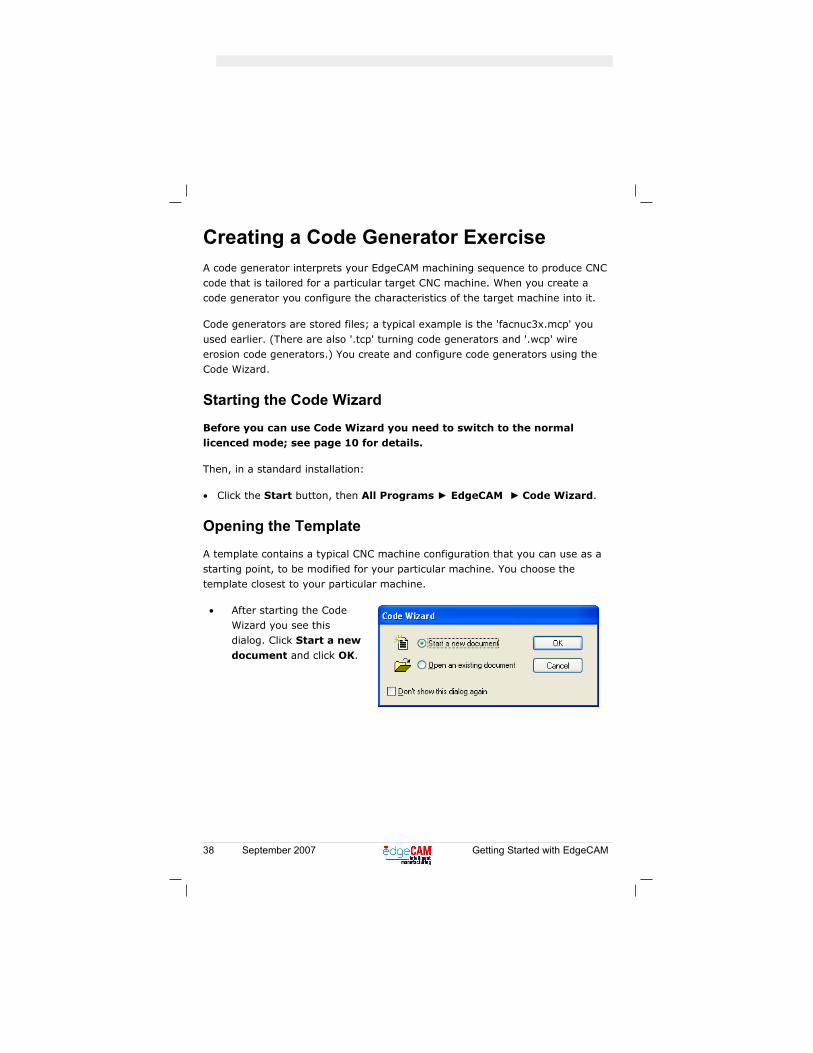
Opening the Template
A template contains a typical CNC machine configuration that you can use as a
starting point, to be modified for your particular machine. You choose the template closest to your particular machine.
• After starting the Code Wizard you see this dialog. Click Start a new
document and click OK.
Getting Started with EdgeCAM September 2007 39
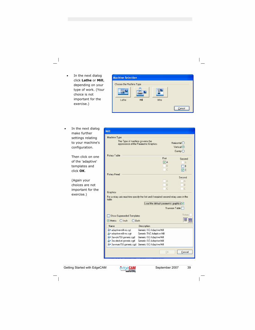
• In the next dialog click Lathe or Mill, depending on your type of work. (Your
choice is not important for the exercise.)
• In the next dialog make further settings relating to your machine's
configuration. Then click on one of the 'adaptive' templates and click OK.
(Again your choices are not important for the exercise.)
40 September 2007 Getting Started with EdgeCAM
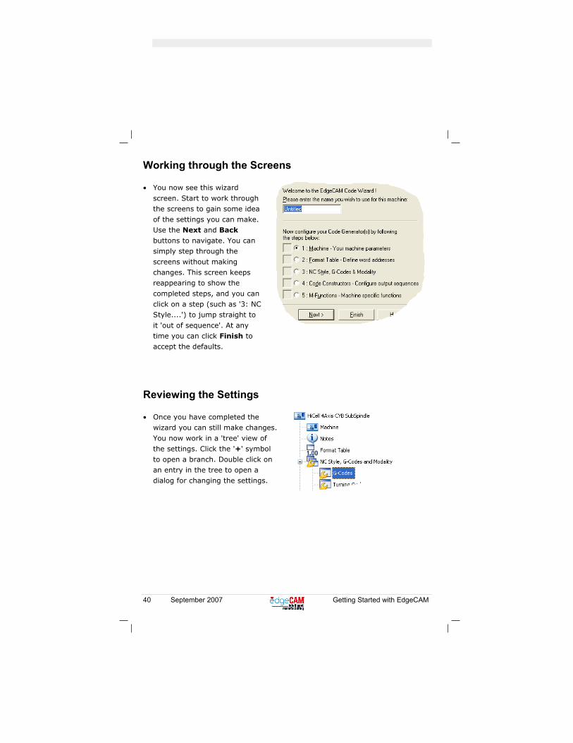
Working through the Screens
• You now see this wizard
screen. Start to work through the screens to gain some idea of the settings you can make. Use the Next and Back buttons to navigate. You can simply step through the
screens without making changes. This screen keeps reappearing to show the completed steps, and you can click on a step (such as '3: NC Style....') to jump straight to
it 'out of sequence'. At any time you can click Finish to accept the defaults.
Reviewing the Settings
• Once you have completed the wizard you can still make changes.
You now work in a 'tree' view of the settings. Click the '+' symbol to open a branch. Double click on an entry in the tree to open a dialog for changing the settings.

Getting Started with EdgeCAM September 2007 41
Saving the Configuration
You can save your settings. Once saved you can restore and change them later,
in the tree view, without having to work through the wizard again:
1. In the toolbar (under the menus), or in the File menu, click Save.
2. Use the dialog to save the '.cgd' file with a name, and in a folder, of your choice.
Compiling
• In the toolbar (under the menus), or in the File menu, click Compile.
A code generator file is created. This is automatically named after the saved
'.cgd' file (or 'Untitled' if there was no save), with the appropriate extension (such as '.mcp' for a milling code generator).
Using the Code Generator
You use the code generator by specifying it as the Machine Tool setting in the Machining Sequence dialog.
You did this in the milling exercise; see page 24.

42 September 2007 Getting Started with EdgeCAM
Index
boundary entities - selecting ............... 26
CAD part - loading .............................. 16
cancelling............................................ 19
clearance - setting .............................. 25
CNC code
editor ............................................. 36
generating ..................................... 36
code generator
compiling ....................................... 41
creating.......................................... 38
specifying ...................................... 24
using.............................................. 41
Code Wizard
opening template........................... 38
saving configurations..................... 41
starting........................................... 38
stepping through............................ 40
defaults file - using correct.................. 14
EdgeCAM
introduction...................................... 5
registering...................................... 11
starting........................................... 11
features
finding............................................ 20
Features window - location ................. 12
Graphics Area - location......................12
hole - drilling........................................25
Hole operation - creating.....................25
installing ................................................8
Isometric view - selecting ....................17
licenced mode - switching to ...............10
lower boss - profiling ...........................32
machining - simulating ........................34
machining sequence - creating ...........24
Manufacture mode - switching to ........24
material - specifying ............................23
Milling exercise - introduction..............15
opening parts ......................................21
pockets - roughing...............................33
profiling operation - creating................32
registering EdgeCAM ..........................11
Roughing operation - creating.............26
saving parts .........................................21
Security Key - fitting ..............................7
sequence........ See machining sequence
setup executable - running....................8
simulating - speed control ...................35
simulating machining...........................34
solid model - loading ...........................16
specifying material ..............................23

Getting Started with EdgeCAM September 2007 43
Standard toolbar location.................... 12
starting EdgeCAM............................... 11
Status Bar - location ........................... 12
stock
creating.......................................... 18
showing translucent....................... 19
Student Edition mode
about ............................................... 7
switching to.................................... 10
template - opening .............................. 38
tool diameter - specifying.................... 27
tool graphic - hiding ............................ 31
ToolStore
selecting tools in ............................27
specifying database .......................23
Undo....................................................19
upper boss - roughing .........................26
User Interface
customising....................................13
overview.........................................12
View Caption - location .......................12
windows locations ...............................12
Zooming ..............................................17


![Skaffold - storage.googleapis.com · [getting-started getting-started] Hello world! [getting-started getting-started] Hello world! [getting-started getting-started] Hello world! 5](https://img.pdfslide.net/doc/110x75/5ec939f2a76a033f091c5ac7/skaffold-getting-started-getting-started-hello-world-getting-started-getting-started.jpg)


