Embed Size (px)
Citation preview
Getting Started with Altera’s DE2-70 Board
This document describes the scope of Altera’s DE2-70 Development and Education Board and the supporting materials provided by the Altera Corporation. It also explains the installation process needed to use a DE2-70 board connected to a computer that has the Quartus II CAD system installed on it.
Contents: Purpose of the DE2-70 Board Scope of the DE2-70 board and Supporting Material Installation and USB-Blaster Driver Using the DE2-70 Board
Altera’s DE2-70 Development and Education Board has been developed to provide an ideal vehicle for learning about digital logic and computer organization in a laboratory setting. It uses the state-of-the-art technology in both hardware and CAD tools to expose students to a wide range of topics covered in typical courses. The power of the board is such that it is also highly suitable for a variety of design projects as well as for the development of sophisticated digital systems. In addition to the DE2-70 board and the associated software, Altera provides supporting materials that include tutorials, laboratory exercises, and interesting demonstrations.
1 Purpose of the DE2-70 Board
University and college courses on the design of logic circuits and computer organization usually include a laboratory component. In a modern curriculum, the laboratory equipment should ideally exemplify state-of-the-art technology and design tools, but be suitable for exercises that range from the simple tasks that illustrate the most basic concepts to challenging designs that require knowledge of advanced topics. From the logistic point of view, it is ideal if the same equipment can be used in all cases. The DE2 board has been designed to provide the desired platform.
2 Scope of the DE2-70 Board and Supporting Material
The DE2-70 board features a powerful Cyclone R II FPGA chip. All important components on the board are connected to the pins of this chip, allowing the user to configure the connection between the various components as desired. For simple experiments, the DE2 board includes a sufficient number of switches (of both toggle and pushbutton variety), LEDs, and 7-segment displays. For more advanced experiments, there are SRAM, SDRAM, and Flash memory chips. For experiments that require a processor and simple I/O interfaces, it is easy to instantiate Altera’s Nios II processor and use interface standards such as RS-232 and PS/2. For experiments that involve sound or video signals, there are standard connectors provided on the board. For large design projects, it is possible to use the SD memory card.
Finally, it is possible to connect other user-designed boards to the DE2-70 board by means of two expansion headers. Software provided with the DE2-70 board features the Quartus II web edition design tools. It also includes a simple monitor program that allows the student to control various parts of the board in an easily understandable manner. There are also several applications that demonstrate the utility of the DE2-70 board. Traditionally, manufacturers of educational FPGA boards have provided a variety of boards and the CAD tools needed to implement designs on these boards. However, there has been a paucity of supporting materials that could be used directly for teaching purposes. Altera’s DE2-70 board is a significant departure from this trend. In addition to the DE2-70 board, Altera Corporation provides a full set of associated exercises that can be performed in a laboratory setting for typical courses on logic design and computer organization. In effect, the DE2-70 board and the available exercises can be used as a ready-to-teach platform for such laboratories. Of course, the DE2-70 board is also likely to be suitable for exercises that have been developed for other hardware platforms and can be ported to the DE2-70 platform.
3 Installation and USB-Blaster Driver
The DE2-70 board is shipped in a package that includes all parts necessary for its operation. The only essential parts are the 12-volt power adapter and the USB cable. There is also a protective plexiglass cover that may be
used in the laboratory environment to protect the board from accidental physical damage. Plug in the 12-volt adapter to provide power to the board. Use the USB cable to connect the USB connector (the one closest to the power switch) on the DE2-70 board to a USB port on a computer that runs the Quartus II software. Turn on the power switch on the DE2-70 board.
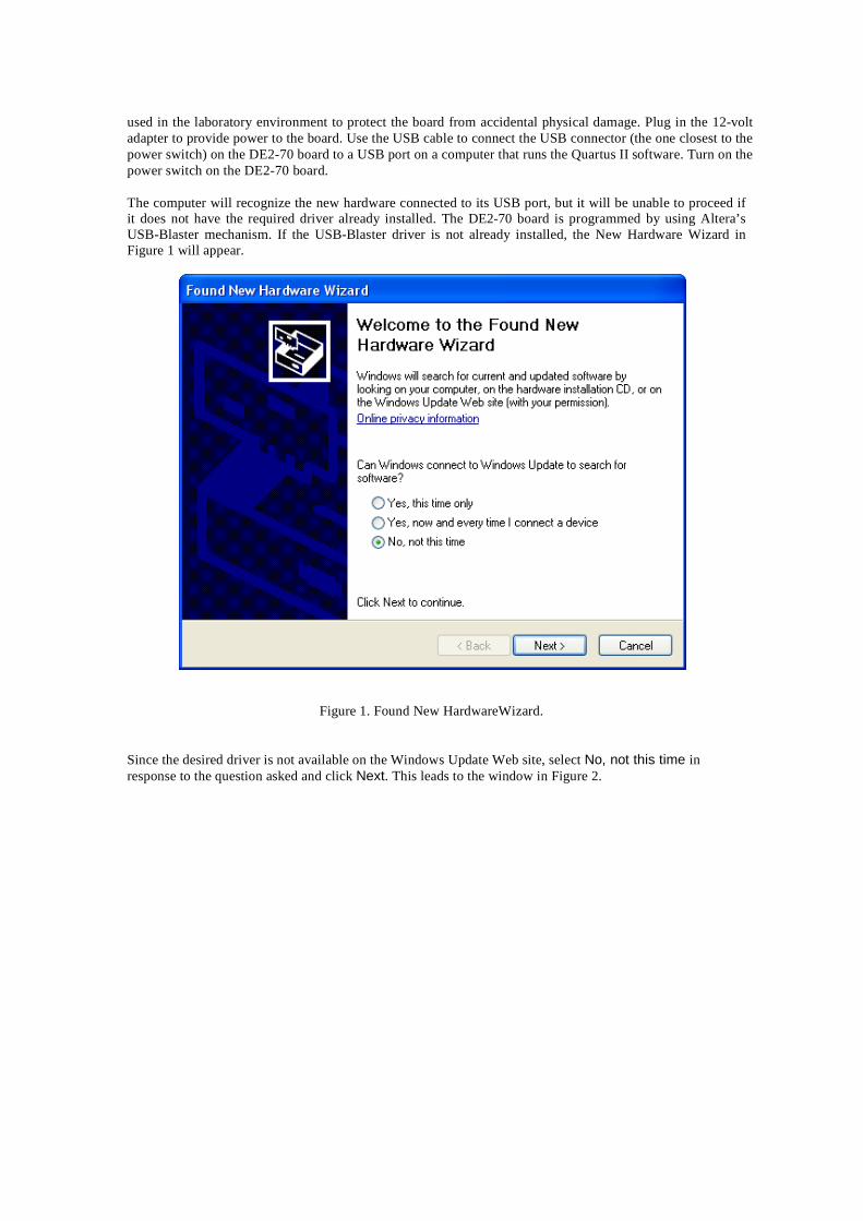
The computer will recognize the new hardware connected to its USB port, but it will be unable to proceed if it does not have the required driver already installed. The DE2-70 board is programmed by using Altera’s USB-Blaster mechanism. If the USB-Blaster driver is not already installed, the New Hardware Wizard in Figure 1 will appear.
Figure 1. Found New HardwareWizard.
Since the desired driver is not available on the Windows Update Web site, select No, not this time in response to the question asked and click Next. This leads to the window in Figure 2.
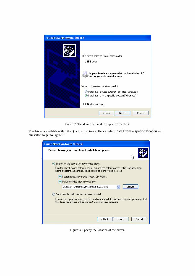
Figure 2. The driver is found in a specific location.
The driver is available within the Quartus II software. Hence, select Install from a specific location and clickNext to get to Figure 3.
Figure 3. Specify the location of the driver.
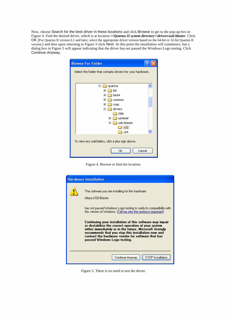
Now, choose Search for the best driver in these locations and click Browse to get to the pop-up box in Figure 4. Find the desired driver, which is at location \<Quartus II system directory>\drivers\usb-blaster. Click OK (For Quartus II version 6.1 and later, select the appropriate driver version based on the 64-bit or 32-bit Quartus II version.) and then upon returning to Figure 3 click Next. At this point the installation will commence, but a dialog box in Figure 5 will appear indicating that the driver has not passed the Windows Logo testing. Click Continue Anyway.
Figure 4. Browse to find the location.
Figure 5. There is no need to test the driver.
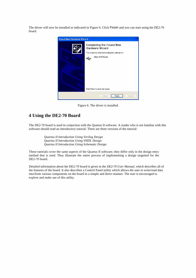
The driver will now be installed as indicated in Figure 6. Click Finish and you can start using the DE2-70 board.
Figure 6. The driver is installed. 4 Using the DE2-70 Board The DE2-70 board is used in conjuction with the Quartus II software. A reader who is not familiar with this software should read an introductory tutorial. There are three versions of the tutorial:
Quartus II Introduction Using Verilog Design Quartus II Introduction Using VHDL Design Quartus II Introduction Using Schematic Design
These tutorials cover the same aspects of the Quartus II software; they differ only in the design entry method that is used. They illustrate the entire process of implementing a design targetted for the DE2-70 board.
Detailed information about the DE2-70 board is given in the DE2-70 User Manual, which describes all of the features of the board. It also describes a Control Panel utility which allows the user to write/read data into/from various components on the board in a simple and direct manner. The user is encouraged to explore and make use of this utility.