Embed Size (px)
Citation preview

ibm.com/redbooks
Getting Started with WebSphere Enterprise Service Bus V6
Martin KeenBill Moore
Antonio CarvalhoMichael Hamann
Prasad ImandiRon Lotter
Philip NortonChristian RinglerGabriel Telerman
Build ESB solutions using SCA and Web services
Implement mediation flows in WebSphere Integration Developer
Learn by example with practical scenarios
Front cover


Getting Started with WebSphere Enterprise Service Bus V6
June 2006
International Technical Support Organization
SG24-7212-00
© Copyright International Business Machines Corporation 2006. All rights reserved.Note to U.S. Government Users Restricted Rights -- Use, duplication or disclosure restricted by GSA ADPSchedule Contract with IBM Corp.
First Edition (June 2006)
This edition applies to WebSphere Integration Developer V6.0.1 and WebSphere Enterprise Service Bus V6.0.1.
Note: Before using this information and the product it supports, read the information in “Notices” on page ix.
Contents
Notices . . . . . . . . . . . . . . . . . . . . . . . . . . . . . . . . . . . . . . . . . . . . . . . . . . . . . . . ixTrademarks . . . . . . . . . . . . . . . . . . . . . . . . . . . . . . . . . . . . . . . . . . . . . . . . . . . . x
Preface . . . . . . . . . . . . . . . . . . . . . . . . . . . . . . . . . . . . . . . . . . . . . . . . . . . . . . . xiThe team that wrote this redbook. . . . . . . . . . . . . . . . . . . . . . . . . . . . . . . . . . . . xiBecome a published author . . . . . . . . . . . . . . . . . . . . . . . . . . . . . . . . . . . . . . . xivComments welcome. . . . . . . . . . . . . . . . . . . . . . . . . . . . . . . . . . . . . . . . . . . . . xiv
Part 1. Product overview . . . . . . . . . . . . . . . . . . . . . . . . . . . . . . . . . . . . . . . . . . . . . . . . . . . . . 1
Chapter 1. Welcome to this redbook . . . . . . . . . . . . . . . . . . . . . . . . . . . . . . . 31.1 An introduction to this document . . . . . . . . . . . . . . . . . . . . . . . . . . . . . . . . . 41.2 How to read this redbook . . . . . . . . . . . . . . . . . . . . . . . . . . . . . . . . . . . . . . 4
Chapter 2. Key technologies and concepts . . . . . . . . . . . . . . . . . . . . . . . . . 72.1 Service-oriented architecture . . . . . . . . . . . . . . . . . . . . . . . . . . . . . . . . . . . 8
2.1.1 Drivers for SOA . . . . . . . . . . . . . . . . . . . . . . . . . . . . . . . . . . . . . . . . . . 82.1.2 Definition of SOA. . . . . . . . . . . . . . . . . . . . . . . . . . . . . . . . . . . . . . . . . 82.1.3 What is a service. . . . . . . . . . . . . . . . . . . . . . . . . . . . . . . . . . . . . . . . 10
2.2 Web services. . . . . . . . . . . . . . . . . . . . . . . . . . . . . . . . . . . . . . . . . . . . . . . 122.2.1 Core technologies of Web services. . . . . . . . . . . . . . . . . . . . . . . . . . 122.2.2 Properties of Web services . . . . . . . . . . . . . . . . . . . . . . . . . . . . . . . . 132.2.3 Web services and SOA . . . . . . . . . . . . . . . . . . . . . . . . . . . . . . . . . . . 15
2.3 Enterprise Service Bus . . . . . . . . . . . . . . . . . . . . . . . . . . . . . . . . . . . . . . . 162.3.1 Enterprise requirements for an ESB . . . . . . . . . . . . . . . . . . . . . . . . . 172.3.2 Minimum ESB capabilities. . . . . . . . . . . . . . . . . . . . . . . . . . . . . . . . . 202.3.3 Communication . . . . . . . . . . . . . . . . . . . . . . . . . . . . . . . . . . . . . . . . . 212.3.4 Extended ESB capabilities . . . . . . . . . . . . . . . . . . . . . . . . . . . . . . . . 21
2.4 Service Component Architecture. . . . . . . . . . . . . . . . . . . . . . . . . . . . . . . . 232.4.1 Anatomy of SCA . . . . . . . . . . . . . . . . . . . . . . . . . . . . . . . . . . . . . . . . 24
2.5 Service Data Objects. . . . . . . . . . . . . . . . . . . . . . . . . . . . . . . . . . . . . . . . . 282.5.1 SDO concepts . . . . . . . . . . . . . . . . . . . . . . . . . . . . . . . . . . . . . . . . . . 282.5.2 Applying SDO to SCA . . . . . . . . . . . . . . . . . . . . . . . . . . . . . . . . . . . . 29
Chapter 3. WebSphere Enterprise Service Bus overview and product positioning. . . . . . . . . . . . . . . . . . . . . . . . . . . . . . . . . . . . . . . . . . 31
3.1 Product overview. . . . . . . . . . . . . . . . . . . . . . . . . . . . . . . . . . . . . . . . . . . . 323.1.1 IBM WebSphere Application Server V6.0 . . . . . . . . . . . . . . . . . . . . . 333.1.2 IBM WebSphere Enterprise Service Bus V6.0 . . . . . . . . . . . . . . . . . 36
© Copyright IBM Corp. 2006. All rights reserved. iii
3.1.3 IBM WebSphere Process Server V6.0 . . . . . . . . . . . . . . . . . . . . . . . 413.1.4 IBM WebSphere MQ V6.0. . . . . . . . . . . . . . . . . . . . . . . . . . . . . . . . . 433.1.5 IBM WebSphere Message Broker V6.0 . . . . . . . . . . . . . . . . . . . . . . 443.1.6 IBM WebSphere Adapters V6.0 . . . . . . . . . . . . . . . . . . . . . . . . . . . . 46
3.2 Enterprise Service Bus product positioning. . . . . . . . . . . . . . . . . . . . . . . . 463.2.1 Comparing WebSphere Enterprise Service Bus to WebSphere Message
Broker . . . . . . . . . . . . . . . . . . . . . . . . . . . . . . . . . . . . . . . . . . . . . . . . 493.2.2 Summary. . . . . . . . . . . . . . . . . . . . . . . . . . . . . . . . . . . . . . . . . . . . . . 513.2.3 IBM SOA Foundation and Patterns for e-business . . . . . . . . . . . . . . 52
3.3 Development environment . . . . . . . . . . . . . . . . . . . . . . . . . . . . . . . . . . . . 523.3.1 User roles . . . . . . . . . . . . . . . . . . . . . . . . . . . . . . . . . . . . . . . . . . . . . 523.3.2 Rational Application Developer V6.0. . . . . . . . . . . . . . . . . . . . . . . . . 543.3.3 WebSphere Integration Developer V6.0 . . . . . . . . . . . . . . . . . . . . . . 54
Part 2. Configuration and usage . . . . . . . . . . . . . . . . . . . . . . . . . . . . . . . . . . . . . . . . . . . . . . 57
Chapter 4. Setting up the development environment . . . . . . . . . . . . . . . . 594.1 Overview of development environment . . . . . . . . . . . . . . . . . . . . . . . . . . . 60
4.1.1 Hardware and software requirements . . . . . . . . . . . . . . . . . . . . . . . . 604.1.2 Consider your current environment. . . . . . . . . . . . . . . . . . . . . . . . . . 60
4.2 Planning for multiple development environments . . . . . . . . . . . . . . . . . . . 614.2.1 Silent installation . . . . . . . . . . . . . . . . . . . . . . . . . . . . . . . . . . . . . . . . 614.2.2 Roles . . . . . . . . . . . . . . . . . . . . . . . . . . . . . . . . . . . . . . . . . . . . . . . . . 62
4.3 Installing the development environment . . . . . . . . . . . . . . . . . . . . . . . . . . 624.3.1 Installing WebSphere Integration Developer. . . . . . . . . . . . . . . . . . . 634.3.2 Using Rational Product Updater . . . . . . . . . . . . . . . . . . . . . . . . . . . . 704.3.3 Starting WebSphere Integration Developer . . . . . . . . . . . . . . . . . . . 75
4.4 Team development . . . . . . . . . . . . . . . . . . . . . . . . . . . . . . . . . . . . . . . . . . 764.5 Integration test considerations . . . . . . . . . . . . . . . . . . . . . . . . . . . . . . . . . 844.6 Troubleshooting installation issues . . . . . . . . . . . . . . . . . . . . . . . . . . . . . . 86
Chapter 5. Setting up the runtime environment . . . . . . . . . . . . . . . . . . . . . 895.1 Overview of the runtime environment . . . . . . . . . . . . . . . . . . . . . . . . . . . . 90
5.1.1 Hardware and software requirements . . . . . . . . . . . . . . . . . . . . . . . . 905.1.2 Consider your current environment. . . . . . . . . . . . . . . . . . . . . . . . . . 905.1.3 What gets installed . . . . . . . . . . . . . . . . . . . . . . . . . . . . . . . . . . . . . . 915.1.4 What gets customized. . . . . . . . . . . . . . . . . . . . . . . . . . . . . . . . . . . . 955.1.5 What gets configured . . . . . . . . . . . . . . . . . . . . . . . . . . . . . . . . . . . . 96
5.2 Stand-alone server topology . . . . . . . . . . . . . . . . . . . . . . . . . . . . . . . . . . . 975.3 Network Deployment topology . . . . . . . . . . . . . . . . . . . . . . . . . . . . . . . . . 995.4 Extending WebSphere Application Server V6. . . . . . . . . . . . . . . . . . . . . 101
5.4.1 Installation . . . . . . . . . . . . . . . . . . . . . . . . . . . . . . . . . . . . . . . . . . . . 1015.4.2 Augmenting profiles . . . . . . . . . . . . . . . . . . . . . . . . . . . . . . . . . . . . 1015.4.3 Final configuration steps . . . . . . . . . . . . . . . . . . . . . . . . . . . . . . . . . 102
iv Getting Started with WebSphere Enterprise Service Bus V6
5.5 Installing WebSphere Enterprise Service Bus. . . . . . . . . . . . . . . . . . . . . 1045.5.1 An initial runtime environment. . . . . . . . . . . . . . . . . . . . . . . . . . . . . 1045.5.2 A common development integration test runtime environment . . . . 113
5.6 Guidelines for staged test and production environments . . . . . . . . . . . . 1295.6.1 Development integration test environment . . . . . . . . . . . . . . . . . . . 1305.6.2 System test environment. . . . . . . . . . . . . . . . . . . . . . . . . . . . . . . . . 1315.6.3 Quality assurance environment. . . . . . . . . . . . . . . . . . . . . . . . . . . . 132
5.7 Problem determination for runtime installation and customization . . . . . 133
Chapter 6. WebSphere Enterprise Service Bus key concepts and related technologies . . . . . . . . . . . . . . . . . . . . . . . . . . . . . . . . . . . . . . . 135
6.1 Product overview. . . . . . . . . . . . . . . . . . . . . . . . . . . . . . . . . . . . . . . . . . . 1366.2 Key terms in WebSphere Enterprise Service Bus. . . . . . . . . . . . . . . . . . 1386.3 Structure of WebSphere Enterprise Service Bus . . . . . . . . . . . . . . . . . . 139
6.3.1 Mediations, service consumers, and service providers. . . . . . . . . . 1396.3.2 Mediation modules . . . . . . . . . . . . . . . . . . . . . . . . . . . . . . . . . . . . . 1406.3.3 Mediation flow components. . . . . . . . . . . . . . . . . . . . . . . . . . . . . . . 1416.3.4 Mediation flows . . . . . . . . . . . . . . . . . . . . . . . . . . . . . . . . . . . . . . . . 1426.3.5 Mediation primitives . . . . . . . . . . . . . . . . . . . . . . . . . . . . . . . . . . . . 144
6.4 Related technologies. . . . . . . . . . . . . . . . . . . . . . . . . . . . . . . . . . . . . . . . 1456.4.1 Service message objects . . . . . . . . . . . . . . . . . . . . . . . . . . . . . . . . 1456.4.2 WebSphere Enterprise Service Bus bindings . . . . . . . . . . . . . . . . . 1486.4.3 Quality of service. . . . . . . . . . . . . . . . . . . . . . . . . . . . . . . . . . . . . . . 1496.4.4 Common event infrastructure . . . . . . . . . . . . . . . . . . . . . . . . . . . . . 1556.4.5 Deployment of mediations. . . . . . . . . . . . . . . . . . . . . . . . . . . . . . . . 156
Chapter 7. WebSphere Integration Developer key concepts and common tasks. . . . . . . . . . . . . . . . . . . . . . . . . . . . . . . . . . . . . . . . . . . . . . 159
7.1 Key terms and concepts . . . . . . . . . . . . . . . . . . . . . . . . . . . . . . . . . . . . . 1607.1.1 User roles . . . . . . . . . . . . . . . . . . . . . . . . . . . . . . . . . . . . . . . . . . . . 1607.1.2 The workbench . . . . . . . . . . . . . . . . . . . . . . . . . . . . . . . . . . . . . . . . 1617.1.3 Workspaces . . . . . . . . . . . . . . . . . . . . . . . . . . . . . . . . . . . . . . . . . . 1627.1.4 Project types . . . . . . . . . . . . . . . . . . . . . . . . . . . . . . . . . . . . . . . . . . 1637.1.5 Perspectives . . . . . . . . . . . . . . . . . . . . . . . . . . . . . . . . . . . . . . . . . . 1637.1.6 Views. . . . . . . . . . . . . . . . . . . . . . . . . . . . . . . . . . . . . . . . . . . . . . . . 1647.1.7 Editors . . . . . . . . . . . . . . . . . . . . . . . . . . . . . . . . . . . . . . . . . . . . . . . 1697.1.8 Mediation module . . . . . . . . . . . . . . . . . . . . . . . . . . . . . . . . . . . . . . 1717.1.9 Exports . . . . . . . . . . . . . . . . . . . . . . . . . . . . . . . . . . . . . . . . . . . . . . 1737.1.10 Imports . . . . . . . . . . . . . . . . . . . . . . . . . . . . . . . . . . . . . . . . . . . . . 1747.1.11 Mediation flow components. . . . . . . . . . . . . . . . . . . . . . . . . . . . . . 1747.1.12 Mediation primitives . . . . . . . . . . . . . . . . . . . . . . . . . . . . . . . . . . . 175
7.2 Workspace configuration. . . . . . . . . . . . . . . . . . . . . . . . . . . . . . . . . . . . . 1767.2.1 Creating the initial workspace . . . . . . . . . . . . . . . . . . . . . . . . . . . . . 176
Contents v
7.2.2 Configuring desktop shortcuts. . . . . . . . . . . . . . . . . . . . . . . . . . . . . 1777.2.3 Capabilities . . . . . . . . . . . . . . . . . . . . . . . . . . . . . . . . . . . . . . . . . . . 178
7.3 Interface definition . . . . . . . . . . . . . . . . . . . . . . . . . . . . . . . . . . . . . . . . . . 1807.3.1 Importing a Project Interchange file . . . . . . . . . . . . . . . . . . . . . . . . 1807.3.2 Working with shared libraries . . . . . . . . . . . . . . . . . . . . . . . . . . . . . 1827.3.3 Modeling business objects . . . . . . . . . . . . . . . . . . . . . . . . . . . . . . . 1847.3.4 Defining interfaces . . . . . . . . . . . . . . . . . . . . . . . . . . . . . . . . . . . . . 191
7.4 Mediation module development . . . . . . . . . . . . . . . . . . . . . . . . . . . . . . . 1947.4.1 Creating a new mediation module. . . . . . . . . . . . . . . . . . . . . . . . . . 1947.4.2 Creating a new mediation flow component . . . . . . . . . . . . . . . . . . . 1967.4.3 Working with exports and imports . . . . . . . . . . . . . . . . . . . . . . . . . . 202
7.5 Running mediation modules . . . . . . . . . . . . . . . . . . . . . . . . . . . . . . . . . . 2077.5.1 Building and cleaning projects . . . . . . . . . . . . . . . . . . . . . . . . . . . . 2077.5.2 Managing test servers. . . . . . . . . . . . . . . . . . . . . . . . . . . . . . . . . . . 2087.5.3 Deploying mediation modules . . . . . . . . . . . . . . . . . . . . . . . . . . . . . 2227.5.4 Testing mediation modules . . . . . . . . . . . . . . . . . . . . . . . . . . . . . . . 224
7.6 Exporting resources . . . . . . . . . . . . . . . . . . . . . . . . . . . . . . . . . . . . . . . . 2247.6.1 Exporting to Project Interchange. . . . . . . . . . . . . . . . . . . . . . . . . . . 2257.6.2 Exporting enterprise applications . . . . . . . . . . . . . . . . . . . . . . . . . . 226
Part 3. Administration and testing . . . . . . . . . . . . . . . . . . . . . . . . . . . . . . . . . . . . . . . . . . . 227
Chapter 8. Testing, debugging and problem determination . . . . . . . . . . 2298.1 Testing tools . . . . . . . . . . . . . . . . . . . . . . . . . . . . . . . . . . . . . . . . . . . . . . 230
8.1.1 Integration Test Client . . . . . . . . . . . . . . . . . . . . . . . . . . . . . . . . . . . 2308.1.2 Web Services Explorer . . . . . . . . . . . . . . . . . . . . . . . . . . . . . . . . . . 2358.1.3 TCP/IP Monitor . . . . . . . . . . . . . . . . . . . . . . . . . . . . . . . . . . . . . . . . 240
8.2 Debugging tools . . . . . . . . . . . . . . . . . . . . . . . . . . . . . . . . . . . . . . . . . . . 2438.2.1 Integration debugger . . . . . . . . . . . . . . . . . . . . . . . . . . . . . . . . . . . . 2438.2.2 Setting up to use the debugger . . . . . . . . . . . . . . . . . . . . . . . . . . . . 2448.2.3 Overview of the Debug perspective . . . . . . . . . . . . . . . . . . . . . . . . 2448.2.4 Using the Integrated Debugger . . . . . . . . . . . . . . . . . . . . . . . . . . . . 246
8.3 Problem determination facilities . . . . . . . . . . . . . . . . . . . . . . . . . . . . . . . 2548.3.1 Isolating problems with the WebSphere Integration Developer
installation. . . . . . . . . . . . . . . . . . . . . . . . . . . . . . . . . . . . . . . . . . . . 2548.3.2 Isolating problems with the WebSphere Enterprise Service Bus
installation. . . . . . . . . . . . . . . . . . . . . . . . . . . . . . . . . . . . . . . . . . . . 2548.3.3 Application logging and tracing . . . . . . . . . . . . . . . . . . . . . . . . . . . . 2548.3.4 Runtime logging and tracing . . . . . . . . . . . . . . . . . . . . . . . . . . . . . . 2558.3.5 Analyzing messages on queue points. . . . . . . . . . . . . . . . . . . . . . . 2568.3.6 Using the CEI for problem determination . . . . . . . . . . . . . . . . . . . . 257
Chapter 9. Administering WebSphere Enterprise Service Bus. . . . . . . . 2619.1 Administrative console . . . . . . . . . . . . . . . . . . . . . . . . . . . . . . . . . . . . . . 262
vi Getting Started with WebSphere Enterprise Service Bus V6
9.2 Deploying mediation modules . . . . . . . . . . . . . . . . . . . . . . . . . . . . . . . . . 2649.2.1 Configuring Web service bindings. . . . . . . . . . . . . . . . . . . . . . . . . . 2649.2.2 Configuring JMS bindings . . . . . . . . . . . . . . . . . . . . . . . . . . . . . . . . 2669.2.3 Methods to deploy service mediation modules . . . . . . . . . . . . . . . . 267
9.3 Mediation module administration. . . . . . . . . . . . . . . . . . . . . . . . . . . . . . . 2719.3.1 Displaying SCA modules. . . . . . . . . . . . . . . . . . . . . . . . . . . . . . . . . 2729.3.2 Displaying imports and exports . . . . . . . . . . . . . . . . . . . . . . . . . . . . 2739.3.3 Displaying interfaces and bindings . . . . . . . . . . . . . . . . . . . . . . . . . 2759.3.4 Changing bindings . . . . . . . . . . . . . . . . . . . . . . . . . . . . . . . . . . . . . 276
Part 4. Development examples . . . . . . . . . . . . . . . . . . . . . . . . . . . . . . . . . . . . . . . . . . . . . . 279
Chapter 10. Preparing for the development examples . . . . . . . . . . . . . . 28110.1 An overview of the development examples. . . . . . . . . . . . . . . . . . . . . . 28210.2 Preparing your environment . . . . . . . . . . . . . . . . . . . . . . . . . . . . . . . . . 283
Chapter 11. Developing integration logic using mediation modules . . . 28911.1 Importing services . . . . . . . . . . . . . . . . . . . . . . . . . . . . . . . . . . . . . . . . . 290
11.1.1 Bindings . . . . . . . . . . . . . . . . . . . . . . . . . . . . . . . . . . . . . . . . . . . . 29011.1.2 Importing an existing Web service . . . . . . . . . . . . . . . . . . . . . . . . 29111.1.3 Connect two modules using SCA binding . . . . . . . . . . . . . . . . . . . 29511.1.4 EIS binding to CICS . . . . . . . . . . . . . . . . . . . . . . . . . . . . . . . . . . . 303
11.2 Creating clients of mediation modules . . . . . . . . . . . . . . . . . . . . . . . . . 31811.2.1 Web services client . . . . . . . . . . . . . . . . . . . . . . . . . . . . . . . . . . . . 31811.2.2 JMS client . . . . . . . . . . . . . . . . . . . . . . . . . . . . . . . . . . . . . . . . . . . 32511.2.3 SCA client . . . . . . . . . . . . . . . . . . . . . . . . . . . . . . . . . . . . . . . . . . . 341
11.3 Using services with mediation modules . . . . . . . . . . . . . . . . . . . . . . . . 34711.3.1 Mapping bindings . . . . . . . . . . . . . . . . . . . . . . . . . . . . . . . . . . . . . 34811.3.2 Request and response flows. . . . . . . . . . . . . . . . . . . . . . . . . . . . . 36111.3.3 Fault handling . . . . . . . . . . . . . . . . . . . . . . . . . . . . . . . . . . . . . . . . 371
Chapter 12. Developing mediation logic using mediation primitives. . . 38112.1 XSL Transformation mediation primitive . . . . . . . . . . . . . . . . . . . . . . . . 38212.2 Database Lookup mediation primitive . . . . . . . . . . . . . . . . . . . . . . . . . . 39412.3 Message Filter mediation primitive . . . . . . . . . . . . . . . . . . . . . . . . . . . . 40612.4 Message Logger mediation primitive. . . . . . . . . . . . . . . . . . . . . . . . . . . 41512.5 Stop mediation primitive . . . . . . . . . . . . . . . . . . . . . . . . . . . . . . . . . . . . 42412.6 Fail mediation primitive . . . . . . . . . . . . . . . . . . . . . . . . . . . . . . . . . . . . . 43212.7 Custom mediation primitive . . . . . . . . . . . . . . . . . . . . . . . . . . . . . . . . . . 439
Chapter 13. Configuring modules to provide quality of service . . . . . . . 45513.1 CEI events. . . . . . . . . . . . . . . . . . . . . . . . . . . . . . . . . . . . . . . . . . . . . . . 45613.2 Security . . . . . . . . . . . . . . . . . . . . . . . . . . . . . . . . . . . . . . . . . . . . . . . . . 46513.3 Transactions . . . . . . . . . . . . . . . . . . . . . . . . . . . . . . . . . . . . . . . . . . . . . 474
Contents vii
Part 5. Appendixes . . . . . . . . . . . . . . . . . . . . . . . . . . . . . . . . . . . . . . . . . . . . . . . . . . . . . . . . 485
Appendix A. Additional material . . . . . . . . . . . . . . . . . . . . . . . . . . . . . . . . 487Locating the Web material . . . . . . . . . . . . . . . . . . . . . . . . . . . . . . . . . . . . . . . 487Using the Web material . . . . . . . . . . . . . . . . . . . . . . . . . . . . . . . . . . . . . . . . . 488
How to use the Web material . . . . . . . . . . . . . . . . . . . . . . . . . . . . . . . . . . 488
Appendix B. Hints and tips. . . . . . . . . . . . . . . . . . . . . . . . . . . . . . . . . . . . . 489Resolving obstacles with WebSphere Integration Developer. . . . . . . . . . . . . 490
Force complete regeneration . . . . . . . . . . . . . . . . . . . . . . . . . . . . . . . . . . 490Update of business objects . . . . . . . . . . . . . . . . . . . . . . . . . . . . . . . . . . . . 490Renaming of resources . . . . . . . . . . . . . . . . . . . . . . . . . . . . . . . . . . . . . . . 491Testing of a mediation flow component stand-alone. . . . . . . . . . . . . . . . . 491Incompatible target runtimes. . . . . . . . . . . . . . . . . . . . . . . . . . . . . . . . . . . 492
Abbreviations and acronyms . . . . . . . . . . . . . . . . . . . . . . . . . . . . . . . . . . . 495
Related publications . . . . . . . . . . . . . . . . . . . . . . . . . . . . . . . . . . . . . . . . . . 497IBM Redbooks . . . . . . . . . . . . . . . . . . . . . . . . . . . . . . . . . . . . . . . . . . . . . . . . 497Other publications . . . . . . . . . . . . . . . . . . . . . . . . . . . . . . . . . . . . . . . . . . . . . 497Online resources . . . . . . . . . . . . . . . . . . . . . . . . . . . . . . . . . . . . . . . . . . . . . . 498How to get IBM Redbooks . . . . . . . . . . . . . . . . . . . . . . . . . . . . . . . . . . . . . . . 498Help from IBM . . . . . . . . . . . . . . . . . . . . . . . . . . . . . . . . . . . . . . . . . . . . . . . . 498
Index . . . . . . . . . . . . . . . . . . . . . . . . . . . . . . . . . . . . . . . . . . . . . . . . . . . . . . . 499
viii Getting Started with WebSphere Enterprise Service Bus V6
Notices
This information was developed for products and services offered in the U.S.A.
IBM may not offer the products, services, or features discussed in this document in other countries. Consult your local IBM representative for information on the products and services currently available in your area. Any reference to an IBM product, program, or service is not intended to state or imply that only that IBM product, program, or service may be used. Any functionally equivalent product, program, or service that does not infringe any IBM intellectual property right may be used instead. However, it is the user's responsibility to evaluate and verify the operation of any non-IBM product, program, or service.
IBM may have patents or pending patent applications covering subject matter described in this document. The furnishing of this document does not give you any license to these patents. You can send license inquiries, in writing, to: IBM Director of Licensing, IBM Corporation, North Castle Drive Armonk, NY 10504-1785 U.S.A.
The following paragraph does not apply to the United Kingdom or any other country where such provisions are inconsistent with local law: INTERNATIONAL BUSINESS MACHINES CORPORATION PROVIDES THIS PUBLICATION "AS IS" WITHOUT WARRANTY OF ANY KIND, EITHER EXPRESS OR IMPLIED, INCLUDING, BUT NOT LIMITED TO, THE IMPLIED WARRANTIES OF NON-INFRINGEMENT, MERCHANTABILITY OR FITNESS FOR A PARTICULAR PURPOSE. Some states do not allow disclaimer of express or implied warranties in certain transactions, therefore, this statement may not apply to you.
This information could include technical inaccuracies or typographical errors. Changes are periodically made to the information herein; these changes will be incorporated in new editions of the publication. IBM may make improvements and/or changes in the product(s) and/or the program(s) described in this publication at any time without notice.
Any references in this information to non-IBM Web sites are provided for convenience only and do not in any manner serve as an endorsement of those Web sites. The materials at those Web sites are not part of the materials for this IBM product and use of those Web sites is at your own risk.
IBM may use or distribute any of the information you supply in any way it believes appropriate without incurring any obligation to you.
Information concerning non-IBM products was obtained from the suppliers of those products, their published announcements or other publicly available sources. IBM has not tested those products and cannot confirm the accuracy of performance, compatibility or any other claims related to non-IBM products. Questions on the capabilities of non-IBM products should be addressed to the suppliers of those products.
This information contains examples of data and reports used in daily business operations. To illustrate them as completely as possible, the examples include the names of individuals, companies, brands, and products. All of these names are fictitious and any similarity to the names and addresses used by an actual business enterprise is entirely coincidental.
COPYRIGHT LICENSE: This information contains sample application programs in source language, which illustrates programming techniques on various operating platforms. You may copy, modify, and distribute these sample programs in any form without payment to IBM, for the purposes of developing, using, marketing or distributing application programs conforming to the application programming interface for the operating platform for which the sample programs are written. These examples have not been thoroughly tested under all conditions. IBM, therefore, cannot guarantee or imply reliability, serviceability, or function of these programs. You may copy, modify, and distribute these sample programs in any form without payment to IBM for the purposes of developing, using, marketing, or distributing application programs conforming to IBM's application programming interfaces.
© Copyright IBM Corp. 2006. All rights reserved. ix
TrademarksThe following terms are trademarks of the International Business Machines Corporation in the United States, other countries, or both:
Redbooks (logo) ™z/OS®ClearCase®Cloudscape™CICS®
DB2 Universal Database™DB2®Everyplace®IBM®IMS™
Rational®Redbooks™Tivoli®WebSphere®
The following terms are trademarks of other companies:
EJB, Java, Java Naming and Directory Interface, JavaMail, JavaServer, JavaServer Pages, JDBC, JSP, J2EE, Visual Java, and all Java-based trademarks are trademarks of Sun Microsystems, Inc. in the United States, other countries, or both.
Windows, and the Windows logo are trademarks of Microsoft Corporation in the United States, other countries, or both.
Linux is a trademark of Linus Torvalds in the United States, other countries, or both.
Other company, product, or service names may be trademarks or service marks of others.
x Getting Started with WebSphere Enterprise Service Bus V6
Preface
IBM® WebSphere® Enterprise Service Bus is a flexible connectivity infrastructure for integrating applications and services. It is designed to enable the development of a service-oriented architecture (SOA).
This IBM Redbook guides you through the capabilities and product features of WebSphere Enterprise Service Bus V6.0. It also contains step-by-step examples of how to build resources for WebSphere Enterprise Service Bus using WebSphere Integration Developer.
� Part 1 introduces WebSphere Enterprise Service Bus and positions it among other SOA and Enterprise Service Bus product offerings from IBM.
� Part 2 describes how to install and configure both WebSphere Enterprise Service Bus and WebSphere Integration Developer and explains how to perform key concepts and tasks using these products.
� Part 3 explains the administration and testing capabilities, including step-by-step examples.
� Part 4 provides development examples that show step-by-step how to develop solutions using mediation primitives, how to integrate with services, and how to deliver qualities of service.
The team that wrote this redbookThis redbook was produced by a team of specialists from around the world working at the International Technical Support Organization (ITSO), Raleigh Center.
Martin Keen is a Senior IT Specialist at the ITSO, Raleigh Center. He writes extensively about WebSphere products, SOA, and Patterns for e-business. He also teaches IBM classes worldwide about WebSphere, SOA, and business process management. Before joining the ITSO, Martin worked in the EMEA WebSphere Lab Services team in Hursley, UK. Martin holds a bachelor’s degree in Computer Studies from Southampton Institute of Higher Education.
Bill Moore is a WebSphere specialist. He writes extensively and teaches classes on WebSphere and related topics. Before joining the ITSO, Bill was a Senior AIM Consultant at the IBM Transarc laboratory in Sydney, Australia. He has 21 years of application development experience on a wide range of computing platforms and using many different coding languages. He holds a
© Copyright IBM Corp. 2006. All rights reserved. xi
Master of Arts degree in English from the University of Waikato, in Hamilton, New Zealand. His current areas of expertise include application development tools, object-oriented programming and design, and e-business application development.
Antonio Carvalho is a System Specialist at IBM Information Technology Services Delivery in Brazil. He joined IBM in 1996 and has been working with Problem Management solutions and Web developing. He holds a degree in Technology from Faculdades Associadas de Sao Paulo (FASP) in Sao Paulo, Brazil. His areas of expertise include experience in object-oriented programming, J2EE™, and application integration.
Michael Hamann is an IT Specialist at IBM Software Services for WebSphere Software Education in Germany. He holds a degree in Geography from the University of Tuebingen, Germany. He has worked for IBM for seven years as an instructor, course developer, and consultant. His areas of expertise include WebSphere MQ, WebSphere Message Broker, WebSphere Adapters, and WebSphere Process Server.
Prasad Imandi is an Advisory Software Engineer in Level 2 support, AIM organization in RTP, NC. He has worked for IBM for 11 years, working with WebSphere MQ, WebSphere Message Broker products, and lately with the Process Choreography component. He holds a Masters degree in Computer Science and Engineering from Jadavpur University, India. His current area of expertise is WebSphere Message Broker.
Ron Lotter is a Senior Software Engineer in the Software Services for WebSphere organization in RTP, NC. He has worked for IBM for 23 years holding various management and technical positions and has seven years of experience with the WebSphere product family. He holds a Masters degree in Electrical Engineering from Case Western Reserve University in Cleveland, Ohio. His areas of expertise include WebSphere Application Server on z/OS® and J2EE development.
Philip Norton is a Software Engineer in the WebSphere organization in Hursley, UK. He has four years of experience servicing WebSphere MQ JMS and developing WebSphere Enterprise Service Bus. He holds a degree in Computer Science from the University of Kent at Canterbury. His areas of expertise include WebSphere MQ, WebSphere ESB, and Java™ programming, including JMS and J2EE development and Application Integration.
Christian Ringler is a certified Senior IT architect and Senior Consultant at IBM Business Consulting Services in Germany. He has worked for five years at IBM Global Services. Before joining IBM, he worked six years for Oracle Consulting. He holds a masters degree in Computer Science from the Friedrich-Alexander University of Erlangen-Nuremberg. His areas of expertise include J2EE
xii Getting Started with WebSphere Enterprise Service Bus V6
architectures, business process integration, and the introduction of service-oriented architecture concepts in client environments, particularly the automotive industry.
Gabriel Telerman is an IT Specialist with IBM Software Services for WebSphere in the UK. He has seven years of experience with IBM. He holds a degree in Computer Studies from Glasgow Caledonian University. His areas of expertise include object-oriented programming, enterprise Java, Web development, Web services, service-oriented architecture, and enterprise application integration.
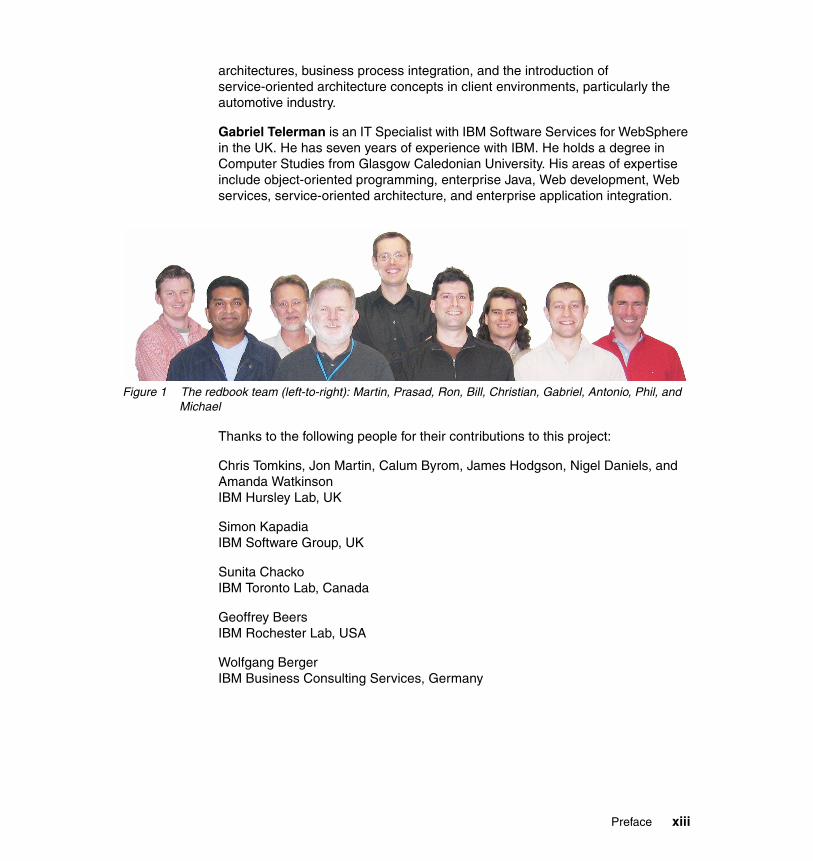
Figure 1 The redbook team (left-to-right): Martin, Prasad, Ron, Bill, Christian, Gabriel, Antonio, Phil, and Michael
Thanks to the following people for their contributions to this project:
Chris Tomkins, Jon Martin, Calum Byrom, James Hodgson, Nigel Daniels, and Amanda WatkinsonIBM Hursley Lab, UK
Simon KapadiaIBM Software Group, UK
Sunita ChackoIBM Toronto Lab, Canada
Geoffrey BeersIBM Rochester Lab, USA
Wolfgang BergerIBM Business Consulting Services, Germany
Preface xiii
Become a published authorJoin us for a two- to six-week residency program! Help write an IBM Redbook dealing with specific products or solutions, while getting hands-on experience with leading-edge technologies. You'll team with IBM technical professionals, Business Partners, or customers.
Your efforts will help increase product acceptance and customer satisfaction. As a bonus, you'll develop a network of contacts in IBM development labs, and increase your productivity and marketability.
Find out more about the residency program, browse the residency index, and apply online at:
ibm.com/redbooks/residencies.html
Comments welcomeYour comments are important to us!
We want our Redbooks™ to be as helpful as possible. Send us your comments about this or other Redbooks in one of the following ways:
� Use the online Contact us review redbook form found at:
ibm.com/redbooks
� Send your comments in an e-mail to:
� Mail your comments to:
IBM Corporation, International Technical Support OrganizationDept. HYTD Mail Station P0992455 South RoadPoughkeepsie, NY 12601-5400
xiv Getting Started with WebSphere Enterprise Service Bus V6
Part 1 Product overview
Part 1
© Copyright IBM Corp. 2006. All rights reserved. 1

2 Getting Started with WebSphere Enterprise Service Bus V6
Chapter 1. Welcome to this redbook
This chapter introduces this redbook to you and provides guidelines for how to read it. It includes the following sections:
� An introduction to this document� How to read this redbook
1
© Copyright IBM Corp. 2006. All rights reserved. 3
1.1 An introduction to this documentA warm welcome to this redbook from the IBM Redbook team. We all assembled for five intense weeks in Raleigh, North Carolina, to put together this resource. We hope you find it a useful read.
This redbook is aimed at integration developers, IT architects, and system administrators. It discusses how WebSphere Enterprise Service Bus fits into service-oriented architecture (SOA) and Enterprise Service Bus strategy from IBM and gives an in-depth overview of the WebSphere Enterprise Service Bus product features.
We have also spent considerable time constructing a wealth of development examples that provide step-by-step instructions for building almost everything that WebSphere Enterprise Service Bus has to offer. You can follow along with these examples, or you can import completed solutions from the additional material that is supplied with this redbook.
1.2 How to read this redbookAs much as we would love for you to read every page of this book cover-to-cover, we anticipate you might not quite have the time! To help you locate the information you need and to provide guidance on which chapters might interest you, this section provides a short description of each chapter.
Part 1. Product overviewThis part introduces readers to the WebSphere Enterprise Service Bus offerings, and SOA related technologies in general.
� Chapter 1. Welcome to this redbook
� Chapter 2. Key technologies and concepts
Provides an overview of SOA, Web services, Enterprise Service Bus, Service Component Architecture, and Service Data Objects.
� Chapter 3. WebSphere Enterprise Service Bus overview and product positioning
Introduces the product features of WebSphere Enterprise Service Bus and related products and positions these product features alongside WebSphere Message Broker.
4 Getting Started with WebSphere Enterprise Service Bus V6
Part 2. Configuration and usageThis part describes how to install and to configure a development and runtime environment and the key concepts, terminology, and tasks in using WebSphere Enterprise Service Bus and WebSphere Integration Developer. This part is aimed primarily at integration developers and system administrators.
� Chapter 4. Setting up the development environment
Describes the installation options for WebSphere Integration Developer, and discusses configuration issues including considerations for building an environment for team development.
� Chapter 5. Setting up the runtime environment
Describes the installation options for WebSphere Enterprise Service Bus and how to plan for test and production environments.
� Chapter 6. WebSphere Enterprise Service Bus key concepts and related technologies
Explains the key terminology used in WebSphere Enterprise Service Bus, focusing on the mediation capabilities. Defines terms such as mediation flow, and mediation primitive.
� Chapter 7. WebSphere Integration Developer key concepts and common tasks
Describes step-by-step how to use WebSphere Integration Developer to complete common tasks, ranging from navigating the Business Integration perspective to building mediation flows.
Part 3. Administration and testingThis part explains many of the key system administration capabilities of WebSphere Enterprise Service Bus and the testing and debugging capabilities of WebSphere Integration Developer.
� Chapter 8. Testing, debugging and problem determination
Describes how to test and debug mediation flows and how to solve runtime problems.
� Chapter 9. Administering WebSphere Enterprise Service Bus
Describes the administration capabilities and tasks that are specific to WebSphere Enterprise Service Bus, including the deployment and management of mediation modules.
Chapter 1. Welcome to this redbook 5
Part 4. Development examplesThis part of the redbook provides step-by-step instructions for building solutions in WebSphere Integration Developer for WebSphere Enterprise Service Bus. Each WebSphere Enterprise Service Bus product feature is explained separately in its own development example. This section is aimed at integration developers who want in-depth hands-on instructions on how to build solutions for WebSphere Enterprise Service Bus.
� Chapter 10. Preparing for the development examples
The development examples all use a common set of services. You must complete the steps in this chapter to prepare your WebSphere Integration Developer workspace before attempting any of the development examples in this redbook.
� Chapter 11. Developing integration logic using mediation modules
Step-by-step development examples for importing Web services, SCA services, and Enterprise Information Systems into mediation modules. Instructions for creating Web service, SCA, and JMS clients to mediation modules. Examples of how to manipulate service calls in a mediation module including changing bindings, request and response flows, and fault handling.
� Chapter 12. Developing mediation logic using mediation primitives
Step-by-step development examples for each of the mediation primitives that are shipped with WebSphere Enterprise Service Bus. Includes development examples for the XSL Transformation, Database Lookup, Message Filter, Message Logging, Stop, Fail, and Custom mediation primitives.
� Chapter 13. Configuring modules to provide quality of service
Step-by-step development examples of how to configure and browse CEI events, apply security, and use transactions.
Part 5. AppendixesThis part of the redbook includes the additional materials for the redbook and a list of hints and tips discovered by the redbook team.
� Appendix A. Additional material
Solutions are provided for each of the development examples in Part 4. Additionally, many of the development examples require resources supplied with this redbook. This appendix describes how to locate the redbook additional material.
� Appendix B. Hints and tips
Lists a few obstacles that the team ran into while creating the development examples for this redbook and workarounds for them.
6 Getting Started with WebSphere Enterprise Service Bus V6
Chapter 2. Key technologies and concepts
This chapter describes the key technologies and concepts that apply to architecting and building solutions in WebSphere Enterprise Service Bus. It includes the following sections:
� Service-oriented architecture� Web services� Enterprise Service Bus� Service Component Architecture� Service Data Objects
2
© Copyright IBM Corp. 2006. All rights reserved. 7
2.1 Service-oriented architectureService-oriented architecture (SOA) is an approach to defining integration architectures based on the concept of a service. Applications collaborate by invoking each others services and services can be composed into larger sequences to implement business processes.
2.1.1 Drivers for SOAThe main driver for SOA is to define an architectural approach that assists in the flexible integration of IT systems. Organizations spend a considerable amount of time and money trying to achieve rapid, flexible integration of IT systems across all elements of the business cycle. The drivers behind this objective include:
� Increasing the speed at which businesses can implement new products and processes, can change existing ones, or can recombine them in new ways
� Reducing implementation and ownership costs of IT systems and the integration between them
� Enabling flexible pricing models by outsourcing more fine-grained elements of the business than were previously possible or by moving from fixed to variable pricing, based on transaction volumes
� Simplifying the integration work that is required by mergers and acquisitions
� Achieving better IT utilization and return on investment
� Achieving implementation of business processes at a level that is independent from the applications and platforms that are used to support the processes
SOA prescribes a set of design principles and an architectural approach to achieve this rapid flexible integration. In the following sections we provide an overview of some of the elements in SOA that achieve this aim.
2.1.2 Definition of SOASOA is an integration architecture approach based on the concept of a service. The business and infrastructure functions that are required to build distributed systems are provided as services that collectively, or individually, deliver application functionality to either end-user applications or other services.
SOA specifies that within any given architecture, there should be a consistent mechanism for services to communicate. That mechanism should be coupled loosely and should support the use of explicit interfaces.
8 Getting Started with WebSphere Enterprise Service Bus V6
SOA brings the benefits of loose coupling and encapsulation to integration at an enterprise level. It applies successful concepts proved by Object Oriented development, Component Based Design, and Enterprise Application Integration technology to an architectural approach for IT system integration.
Services are the building blocks to SOA, providing function out of which distributed systems can be built. Services can be invoked independently by either external or internal service consumers to process simple functions, or can be chained together to form more complex functionality and so to quickly devise new functionality.
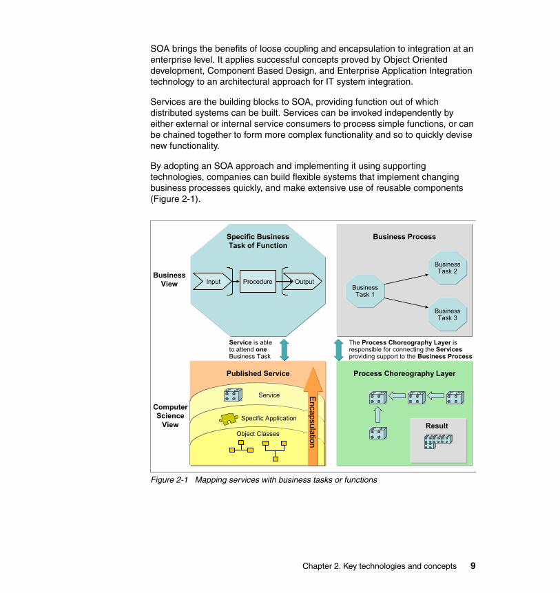
By adopting an SOA approach and implementing it using supporting technologies, companies can build flexible systems that implement changing business processes quickly, and make extensive use of reusable components (Figure 2-1).
Figure 2-1 Mapping services with business tasks or functions
Process Choreography Layer
Z
Input OutputProcedureBusiness
View
Specific BusinessTask of Function
ComputerScience
View
Published Service
Service is able to attend oneBusiness Task
Service
Specific Application
Object Classes
Encapsulation
Business Process
BusinessTask 1
BusinessTask 2
BusinessTask 3
The Process Choreography Layer is responsible for connecting the Services providing support to the Business Process
Result
Chapter 2. Key technologies and concepts 9
2.1.3 What is a serviceHaving outlined SOA as being an architectural approach to defining integration architectures based on services, it is important to define what is meant by a service in this context in order to fully describe SOA and to understand what can be achieved by using it. A service can be defined as any discrete function that can be offered to an external consumer. This function can be an individual business function or a collection of functions that together form a process.
There are many additional aspects to a service that we must also consider in the definition of a service within an SOA. The most commonly agreed-on aspects are that services:
� Encapsulate reusable business functions
� Are defined by explicit, implementation-independent interfaces
� Are invoked through communication protocols that stress location transparency and interoperability
Reusable business functionsA service can be any business function. In an SOA, however, it is preferable that the function is genuinely reusable. The goal of a service in an SOA is that it can be used and reused by one or more systems that participate in the architecture. For example, while the reuse of a Java logging API can be described as design time (when a decision is made to reuse an available package and bind it into application code), the intention of SOA is to achieve the reuse of services at:
� Runtime
Each service is deployed in one place and one place only and is invoked remotely by anything that must use it. The advantage of this approach is that changes to the service (for example, to the calculation algorithm or the reference data on which it depends) need only be applied in a single place.
� Deployment time
Each service is built once but redeployed locally to each system or to the set of systems that must use it. The advantage of this approach is increased flexibility to achieve performance targets or to customize the service (perhaps according to geography).
10 Getting Started with WebSphere Enterprise Service Bus V6
Explicit implementation-independent interfacesThe use of explicit interfaces to define and to encapsulate service function is of particular importance to making services genuinely reusable. The interface should encapsulate only those aspects of process and behavior that are used in the interaction between the service consumer and the service provider. An explicit interface definition, or contract, is used to bind a service consumer and a service provider. It should specify only the mutual behavior that is required for the interaction and should specify nothing about the implementation of the consumer or the provider.
By explicitly defining the interaction in this way, those aspects of either system (for example the platform on which they are based) that are not part of the interaction are free to change without affecting the other system. This implementation-independent interface allows either system to change implementation or identity freely.
Communication protocols that stress location transparencySOA does not specify that any specific protocol be used to provide access to a service. A key principle in SOA is that a service is not defined by the communication protocol that it uses but instead, should be defined in a protocol-independent way that allows different protocols to be used to access the same service.
Ideally, a service should only be defined once, through a service interface, and should have many implementations with different access protocols. This type of definition helps to increase the reusability of any service definition.
Chapter 2. Key technologies and concepts 11
2.2 Web servicesThis section describes the core technologies of Web services, as well as how an SOA uses Web services.
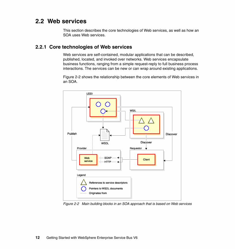
2.2.1 Core technologies of Web servicesWeb services are self-contained, modular applications that can be described, published, located, and invoked over networks. Web services encapsulate business functions, ranging from a simple request-reply to full business process interactions. The services can be new or can wrap around existing applications.
Figure 2-2 shows the relationship between the core elements of Web services in an SOA.
Figure 2-2 Main building blocks in an SOA approach that is based on Web services
12 Getting Started with WebSphere Enterprise Service Bus V6
The following are the core technologies used for Web services.
� XML: Extensible Markup Language (XML) is the markup language that underlies most of the specifications used for Web services. XML is a generic language that can describe any kind of content in a structured way, separated from its presentation to a specific device.
� SOAP: Simple Object Access Protocol (SOAP) is a network, transport, and programming language and platform-neutral protocol that allows a client to call a remote service. The message format is XML.
� WSDL: Web Services Description Language (WSDL) is an XML-based interface and implementation description language. The service provider uses a WSDL document in order to specify the operations that a Web service provides and the parameters and data types of these operations. A WSDL document also contains the service access information.
� WSIL: Web Services Inspection Language (WSIL) is an XML-based specification that locates Web services without using UDDI. However, WSIL can also be used with UDDI, that is, it is orthogonal to UDDI and does not replace it.
� UDDI: Universal Description, Discovery, and Integration (UDDI) is both a client-side API and a SOAP-based server implementation that can be used to store and retrieve information about service providers and Web services.
2.2.2 Properties of Web servicesAll Web services share the following properties:
� Web services are self-contained
On the client side, no additional software is required. A programming language with XML and HTTP client support is enough to get you started. On the server side, merely an HTTP server and a SOAP server are required. It is possible to enable an existing application for Web services without writing a single line of code.
� Web services are self-describing
The definition of the message format travels with the message. No external metadata repositories or code generation tools are required.
� Web services can be published, located, and invoked across the Web
This technology uses established lightweight Internet standards such as HTTP. It leverages the existing infrastructure. Some additional standards that are required to do so include SOAP, WSDL, and UDDI.
Chapter 2. Key technologies and concepts 13

� Web services are modular
Simple Web services can be aggregated to more complex ones, either using workflow techniques or by calling lower-layer Web services from a Web service implementation. Web services can be chained together to perform higher-level business functions. This shortens development time and enables best-of-breed implementations.
� Web services are language-independent and interoperable
The client and server can be implemented in different environments. Existing code does not have to be changed to be Web service enabled. Basically, you can use any language to implement Web service clients and servers. In this redbook, we discuss only the use of Java for Web services.
� Web services are inherently open and standard-based
XML and HTTP are the major technical foundation for Web services. A large part of the Web service technology has been built using open-source projects. Therefore, vendor independence and interoperability are realistic goals.
� Web services are loosely coupled
Traditionally, application design has depended on tight interconnections at both ends. Web services require a simpler level of coordination that allows a more flexible reconfiguration for an integration of the services in question.
� Web services are dynamic
Dynamic e-business can become reality using Web services, because with UDDI and WSDL, the Web service description and discovery can be automated. In addition, Web services can be implemented and deployed without disturbing the clients that use them.
� Web services provide programmatic access
The approach provides no graphical user interface; it operates at the code level. Service consumers have to know the interfaces to Web services but do not have to know the implementation details of services.
� Web services provide the ability to wrap existing applications
Already existing stand-alone applications can easily be integrated into the service-oriented architecture by implementing a Web service as an interface.
� Web services build on proven, mature technology
There are a lot of commonalities, as well as a few fundamental differences, with other distributed computing frameworks.
14 Getting Started with WebSphere Enterprise Service Bus V6
2.2.3 Web services and SOASOA represents a conceptual architecture of how to integrate applications. Web services are a specific set of standards and specifications that are one method of enabling SOA.
There are many logical links between Web services and SOA that suggest they are complementary:
� Web services provide an open standard and machine-readable model for creating explicit, implementation-independent descriptions of service interfaces.
� Web services provide communication mechanisms that are location-transparent and interoperable.
� Web services are evolving, through Business Process Execution Language for Web Services (WS-BPEL), document-style SOAP, and Web Services Definition Language (WSDL), as well as technologies such as WS-ResourceFramework to support the technical implementation of well-designed services that encapsulate and model reusable function in a flexible manner.
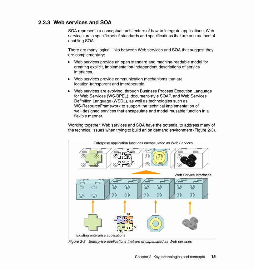
Working together, Web services and SOA have the potential to address many of the technical issues when trying to build an on demand environment (Figure 2-3).
Figure 2-3 Enterprise applications that are encapsulated as Web services
Web Service Interfaces
Existing enterprise applications
Enterprise application functions encapsulated as Web Services
Chapter 2. Key technologies and concepts 15

2.3 Enterprise Service BusThe Enterprise Service Bus (ESB) is emerging as a middleware infrastructure component that supports the implementation of SOA within an enterprise. ESB supports the concepts of SOA implementation by:
� Decoupling the consumer’s view of a service from the actual implementation of the service
� Decoupling technical aspects of service interactions
� Integrating and managing services in the enterprise
These concepts are achieved by replacing direct connections between service consumers and providers with a hub and spoke architecture (Figure 2-4).
Figure 2-4 Direct connection and central hub integration styles
Direct Connection
Hub and Spoke
Service Consumer
Service Consumer
Service Consumer
Service Provider
Service Provider
Service Provider
Service Consumer
Service Consumer
Service Consumer
Service Provider
Service Provider
Service Provider
Hub:ESB
16 Getting Started with WebSphere Enterprise Service Bus V6
You can use the ESB to perform some of the following middleware functions:
� Map service requests from one protocol and address to another
� Transform data formats
� Support a variety of security and transactional models between service consumers and service providers and recognize that consumers and providers might support or require different models
� Aggregate or disaggregate service requests and responses
� Support communication protocols between multiple platforms with appropriate qualities of service
� Provide messaging capabilities such as message correlation and publish/subscribe to support different messaging models, such as events and asynchronous request/response
2.3.1 Enterprise requirements for an ESBUsing an ESB to implement an SOA has a number of advantages. In an SOA, services should, by definition, be reusable by a number of different consumers, so that the benefits of reduced connections are achieved. In addition the ESB:
� Supports high volumes of individual interactions.
� Supports more established integration styles, such as message-oriented and event-driven integration, to extend the reach of the SOA. The ESB should allow applications to be SOA-enabled either directly or through the use of adapters.
� Supports centralization of enterprise-level qualities of service and manageability requirements into the hub.
Chapter 2. Key technologies and concepts 17
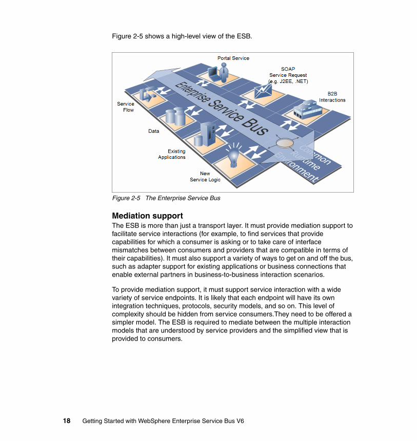
Figure 2-5 shows a high-level view of the ESB.
Figure 2-5 The Enterprise Service Bus
Mediation supportThe ESB is more than just a transport layer. It must provide mediation support to facilitate service interactions (for example, to find services that provide capabilities for which a consumer is asking or to take care of interface mismatches between consumers and providers that are compatible in terms of their capabilities). It must also support a variety of ways to get on and off the bus, such as adapter support for existing applications or business connections that enable external partners in business-to-business interaction scenarios.
To provide mediation support, it must support service interaction with a wide variety of service endpoints. It is likely that each endpoint will have its own integration techniques, protocols, security models, and so on. This level of complexity should be hidden from service consumers.They need to be offered a simpler model. The ESB is required to mediate between the multiple interaction models that are understood by service providers and the simplified view that is provided to consumers.
18 Getting Started with WebSphere Enterprise Service Bus V6

Protocol independenceServices can be offered by a variety of sources. Without an ESB infrastructure, any service consumer that needs to invoke a service needs to connect directly to a service provider using the protocol, transport, and interaction pattern that is used by the provider. With an ESB, the infrastructure shields the consumer from the details of how to connect to the provider.
In an ESB, there is no direct connection between the consumer and provider. Consumers access the ESB to invoke services and the ESB acts as an intermediary, passing the request to the provider using the appropriate protocol, transport, and interaction pattern for the provider. This mediation enables the ESB to shield the consumer from the infrastructure details of how to connect to the provider. The ESB should support several integration mechanisms, all of which could be described as invoking services through specific addresses and protocols, even if in some cases the address is the name of a CICS® transaction and the protocol is a J2EE resource adapter that integrates with the CICS Transaction Gateway. By using the ESB, the consumers are unaware of how the service is invoked on the provider.
Because the ESB removes the direct connection between service consumer and providers, an ESB enables the substitution of one service implementation by another with no effect to the consumers of that service. Thus, an ESB allows the reach of an SOA to extend to non-SOA-enabled service providers. It can also be used to support migration of the non-SOA providers to using an SOA approach without impacting the consumers of the service.
Support for multiple interaction patternsTo fully support the variety of interaction patterns that are required in a comprehensive service-oriented architecture (for example, request/response, publish/subscribe, and events), the ESB must support in one infrastructure the three major styles of Enterprise Integration:
� SOAs in which applications communicate through reusable services with well-defined, explicit interfaces. Service-oriented interactions leverage underlying messaging and event communication models.
� Message-driven architectures in which applications send messages through the ESB to receiving applications.
� Event-driven architectures in which applications generate and consume messages independently of one another.
The ESB does this while providing additional capabilities to mediate or to transform service messages and interactions, enabling a wide variety of behaviors and supporting the various models of coupling interaction.
Chapter 2. Key technologies and concepts 19
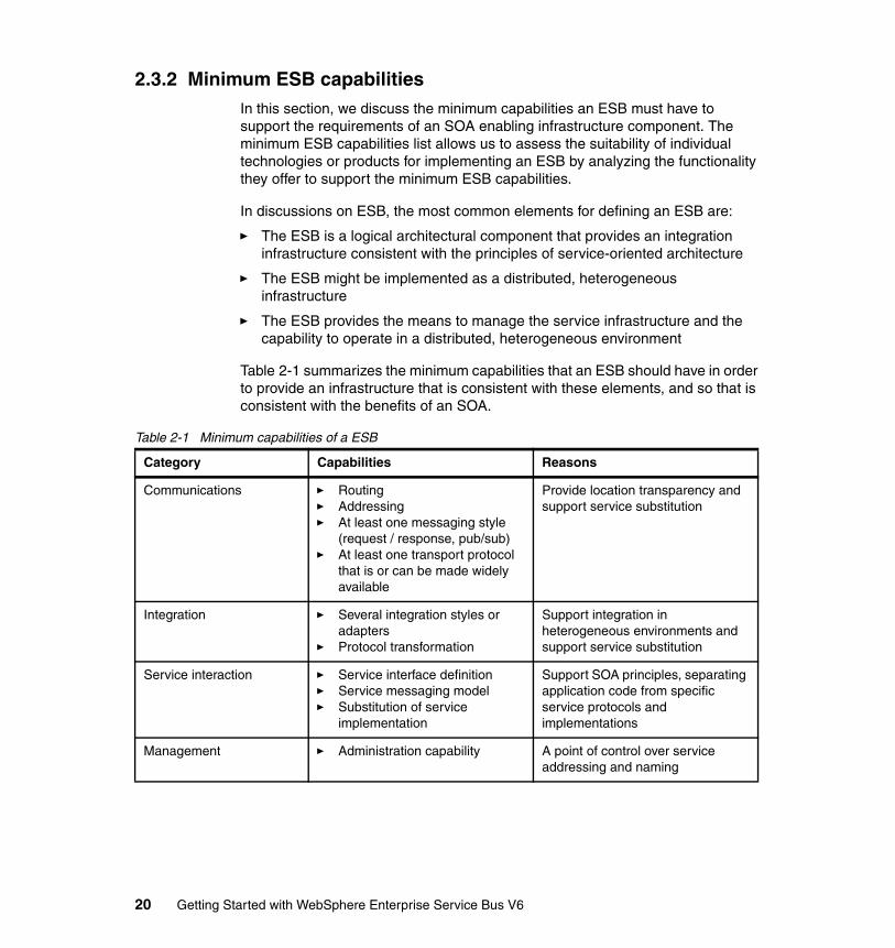
2.3.2 Minimum ESB capabilitiesIn this section, we discuss the minimum capabilities an ESB must have to support the requirements of an SOA enabling infrastructure component. The minimum ESB capabilities list allows us to assess the suitability of individual technologies or products for implementing an ESB by analyzing the functionality they offer to support the minimum ESB capabilities.
In discussions on ESB, the most common elements for defining an ESB are:
� The ESB is a logical architectural component that provides an integration infrastructure consistent with the principles of service-oriented architecture
� The ESB might be implemented as a distributed, heterogeneous infrastructure
� The ESB provides the means to manage the service infrastructure and the capability to operate in a distributed, heterogeneous environment
Table 2-1 summarizes the minimum capabilities that an ESB should have in order to provide an infrastructure that is consistent with these elements, and so that is consistent with the benefits of an SOA.
Table 2-1 Minimum capabilities of a ESB
Category Capabilities Reasons
Communications � Routing� Addressing� At least one messaging style
(request / response, pub/sub)� At least one transport protocol
that is or can be made widely available
Provide location transparency and support service substitution
Integration � Several integration styles or adapters
� Protocol transformation
Support integration in heterogeneous environments and support service substitution
Service interaction � Service interface definition� Service messaging model� Substitution of service
implementation
Support SOA principles, separating application code from specific service protocols and implementations
Management � Administration capability A point of control over service addressing and naming
20 Getting Started with WebSphere Enterprise Service Bus V6
2.3.3 CommunicationThe ESB needs to supply a communication layer to support service interactions. It should support communication through a variety of protocols. It should provide underlying support for message and event oriented middleware and integrate with existing HTTP infrastructure and other enterprise application integration (EAI) technologies. As a minimum capability the ESB should support at least the protocols that make sense given the requirements of a specific situation.
The ESB should be able to route between all these communication technologies through a consistent naming and administration model.
Service interactionThe ESB needs to support SOA concepts for the use of interfaces and support declaration service operations and quality of service requirements. The ESB should also support service messaging models consistent with those interfaces, and be capable of transmitting the required interaction context, such as security, transaction or message correlation information.
IntegrationThe ESB should support linking to a variety of systems that do not directly support service-style interactions so that a variety of services can be offered in a heterogeneous environment. This linking includes existing systems, packaged applications and other EAI technologies. Integration technologies might be protocols (for example JDBC™, FTP, or EDI) or adapters such as the J2EE Connector Architecture resource adapters or WebSphere Business Integration Adapters. It also includes service client invocation through client APIs for various languages (Java, C++, C#) and platforms (J2EE, .Net), CORBA and RMI.
ManagementAs with any other infrastructure component the ESB needs to have administration capabilities to allow it to be managed and monitored and so to provide a point of control over service addressing and naming. In addition, it should be capable of integration into systems management software.
2.3.4 Extended ESB capabilitiesThe minimum capabilities that are described in 2.3.2, “Minimum ESB capabilities” on page 20 can help assess the suitability of individual technologies or products for implementing an ESB. However, these minimum capabilities only establish which technologies are candidates. The detailed requirements of any particular scenario drive additional ESB capabilities that can then be used to select specific, appropriate products.
Chapter 2. Key technologies and concepts 21
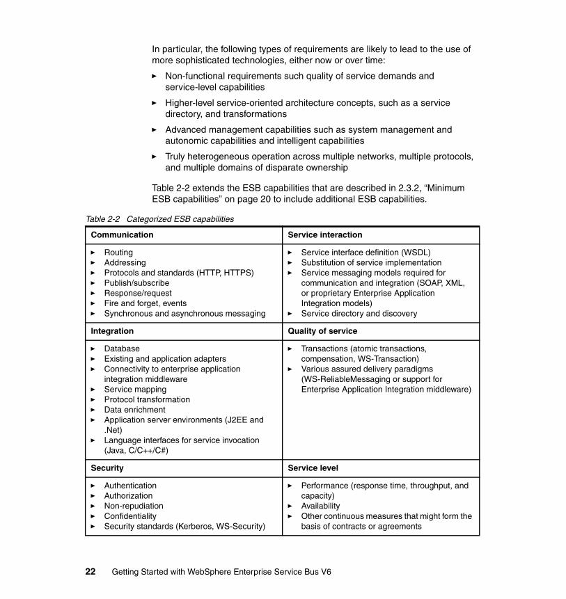
In particular, the following types of requirements are likely to lead to the use of more sophisticated technologies, either now or over time:
� Non-functional requirements such quality of service demands and service-level capabilities
� Higher-level service-oriented architecture concepts, such as a service directory, and transformations
� Advanced management capabilities such as system management and autonomic capabilities and intelligent capabilities
� Truly heterogeneous operation across multiple networks, multiple protocols, and multiple domains of disparate ownership
Table 2-2 extends the ESB capabilities that are described in 2.3.2, “Minimum ESB capabilities” on page 20 to include additional ESB capabilities.
Table 2-2 Categorized ESB capabilities
Communication Service interaction
� Routing� Addressing� Protocols and standards (HTTP, HTTPS)� Publish/subscribe� Response/request� Fire and forget, events� Synchronous and asynchronous messaging
� Service interface definition (WSDL)� Substitution of service implementation� Service messaging models required for
communication and integration (SOAP, XML, or proprietary Enterprise Application Integration models)
� Service directory and discovery
Integration Quality of service
� Database� Existing and application adapters� Connectivity to enterprise application
integration middleware� Service mapping� Protocol transformation� Data enrichment� Application server environments (J2EE and
.Net)� Language interfaces for service invocation
(Java, C/C++/C#)
� Transactions (atomic transactions, compensation, WS-Transaction)
� Various assured delivery paradigms (WS-ReliableMessaging or support for Enterprise Application Integration middleware)
Security Service level
� Authentication� Authorization� Non-repudiation� Confidentiality� Security standards (Kerberos, WS-Security)
� Performance (response time, throughput, and capacity)
� Availability� Other continuous measures that might form the
basis of contracts or agreements
22 Getting Started with WebSphere Enterprise Service Bus V6
2.4 Service Component ArchitectureService Component Architecture (SCA) was developed to simplify the integration between business applications and the development of new services. SOA is an abstract way to interpret the services and his correlations, SCA is defined as the implementation of the SOA architecture. Its standards allow the creation of services and the integration between them.
SCA separates application business logic and the implementation details. It provides a model that defines interfaces, implementations, and references in a technology neutral way, letting you then bind these elements to any technology specific implementation. The ability to separate business logic from infrastructure logic reduces the IT resources needed to build an enterprise application, and gives developers more time to work on solving a particular business problem rather than focusing on the details of which implementation technology to use.
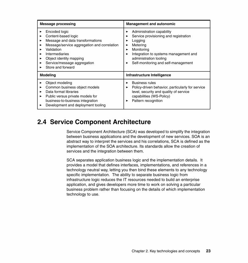
Message processing Management and autonomic
� Encoded logic� Content-based logic� Message and data transformations� Message/service aggregation and correlation� Validation� Intermediaries� Object identity mapping� Service/message aggregation� Store and forward
� Administration capability� Service provisioning and registration� Logging� Metering� Monitoring� Integration to systems management and
administration tooling� Self-monitoring and self-management
Modeling Infrastructure Intelligence
� Object modeling� Common business object models� Data format libraries� Public versus private models for
business-to-business integration� Development and deployment tooling
� Business rules� Policy-driven behavior, particularly for service
level, security and quality of service capabilities (WS-Policy)
� Pattern recognition
Chapter 2. Key technologies and concepts 23
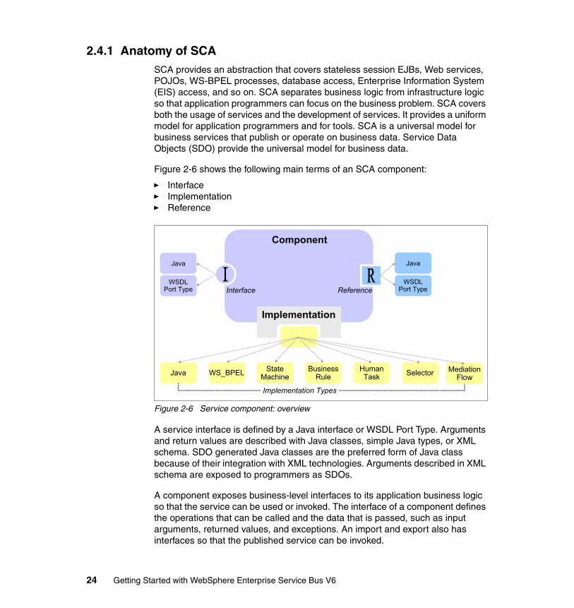
2.4.1 Anatomy of SCASCA provides an abstraction that covers stateless session EJBs, Web services, POJOs, WS-BPEL processes, database access, Enterprise Information System (EIS) access, and so on. SCA separates business logic from infrastructure logic so that application programmers can focus on the business problem. SCA covers both the usage of services and the development of services. It provides a uniform model for application programmers and for tools. SCA is a universal model for business services that publish or operate on business data. Service Data Objects (SDO) provide the universal model for business data.
Figure 2-6 shows the following main terms of an SCA component:
� Interface� Implementation� Reference
Figure 2-6 Service component: overview
A service interface is defined by a Java interface or WSDL Port Type. Arguments and return values are described with Java classes, simple Java types, or XML schema. SDO generated Java classes are the preferred form of Java class because of their integration with XML technologies. Arguments described in XML schema are exposed to programmers as SDOs.
A component exposes business-level interfaces to its application business logic so that the service can be used or invoked. The interface of a component defines the operations that can be called and the data that is passed, such as input arguments, returned values, and exceptions. An import and export also has interfaces so that the published service can be invoked.
HumanTask
HumanTaskJavaJava WS_BPELWS_BPEL Business
RuleBusiness
Rule SelectorSelectorStateMachine
StateMachine
Implementation Types
Java
WSDLPort Type Interface Reference
JavaJava
WSDLPort Type
Component
Implementation
MediationFlow
MediationFlow
24 Getting Started with WebSphere Enterprise Service Bus V6

All components have interfaces of the WSDL type. Only Java components support Java-type interfaces. If a component, import or export, has more than one interface, all interfaces must be the same type.
A component can be called synchronously or asynchronously; this is independent of whether the implementation is synchronous or asynchronous. The component interfaces are defined in the synchronous form and asynchronous support is also generated for them. You can specify a preferred interaction style as synchronous or asynchronous. The asynchronous type advertises to users of the interface that it contains at least one operation that can take a significant amount of time to complete. As a consequence, the calling service must avoid keeping a transaction open while waiting for the operation to complete and send its response. The interaction style applies to all the operations in the interface.
You can also apply a role-based permission qualifier to an interface so that only authorized applications can invoke the service with that interface. If the operations require different levels of permission for their use, you must define separate interfaces to control their access.
A service can be implemented in a range of languages (for example Java, WS-BPEL, state-machine definitions, and so on). When implementing a service, the focus is on the business purpose and less on infrastructure technology.
SCA and non-SCA services can use other service components in their implementations. They do not hard code the other services they use. They declare soft links called service references. Service wires resolve service references. You can use SCA wiring to create SCA applications by component assembly.
Figure 2-7 on page 26 shows a service component and a number of references. When a component wants to use the services of another component, it must have a partner reference or simply a reference. We can consider an in-line reference, which means that the referenced service component is defined within the same scope of the referencing component. In other words, both components are defined within the same module.
Applications that are not defined as SCA components, for example, JavaServer™ Pages™ (JSPs), can still invoke SCA components. They do so through the use of stand-alone references. Stand-alone references contain partner references that identify the components to call. Stand-alone references do not have any implementation or interface.
Chapter 2. Key technologies and concepts 25
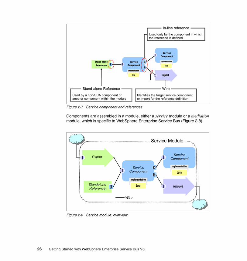
Figure 2-7 Service component and references
Components are assembled in a module, either a service module or a mediation module, which is specific to WebSphere Enterprise Service Bus (Figure 2-8).
Figure 2-8 Service module: overview
Used by a non-SCA component or another component within the module
Stand-alone Reference
Used only by the component in which the reference is defined
In-line reference
Identifies the target service component or import for the reference definition
Wire
Import
Export
StandaloneReference
ServiceComponent
ServiceComponent
Service Module
Wire
26 Getting Started with WebSphere Enterprise Service Bus V6
The implementations of components that are used in a module assembly might reside within the module. Components that belong to other modules can be used through imports. Components in different modules can be wired together by publishing the services as exports that have their interfaces and dragging the exports into the required assembly diagram to create imports.
When wiring components, you can also specify quality of service qualifiers on the implementations, partner references, and interfaces of the component.
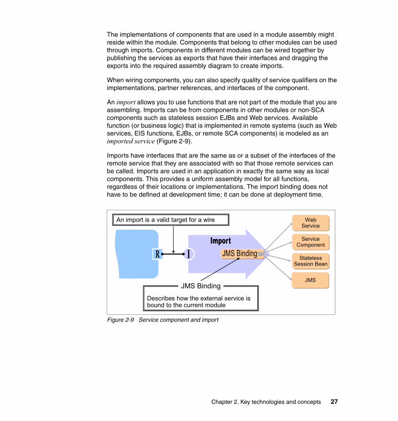
An import allows you to use functions that are not part of the module that you are assembling. Imports can be from components in other modules or non-SCA components such as stateless session EJBs and Web services. Available function (or business logic) that is implemented in remote systems (such as Web services, EIS functions, EJBs, or remote SCA components) is modeled as an imported service (Figure 2-9).
Imports have interfaces that are the same as or a subset of the interfaces of the remote service that they are associated with so that those remote services can be called. Imports are used in an application in exactly the same way as local components. This provides a uniform assembly model for all functions, regardless of their locations or implementations. The import binding does not have to be defined at development time; it can be done at deployment time.
Figure 2-9 Service component and import
An import is a valid target for a wire
Describes how the external service is bound to the current module
JMS Binding
WebService
ServiceComponent
StatelessSession Bean
JMS
Chapter 2. Key technologies and concepts 27

An export is a published interface from a component (Figure 2-10) that offers the component business service to the outside world, for example, as a Web service. Exports have interfaces that are the same as or a subset of the interfaces of the component that they are associated with so that the published service can be called. An export dragged from another module into an assembly diagram automatically creates an import.
Figure 2-10 Service component and export
2.5 Service Data ObjectsBusiness data that is exchanged in an integrated application in WebSphere Enterprise Service Bus is represented by business objects. The objects are based on Service Data Objects (SDOs), which is a new data access technology.
2.5.1 SDO conceptsThere are a a few key SDO concepts that can provide a framework for understanding business object architecture, including the design and use of business objects in WebSphere Enterprise Service Bus. The fundamental concept in the SDO architecture is the data object. In fact, the term SDO is often used interchangeably with the term data object. A data object is a data structure that holds primitive data, multi-valued fields (other data objects), or both.
The data object also has references to metadata that provide information about the data found in the data object. In the SDO programming model, data objects are represented by the commonj.sdo.DataObject Java interface definition. This interface includes method definitions that allow clients to obtain and set the properties associated with DataObject.
Describes how the service is bound externally
esbBinding
Identifies the component to be exported
Target
WebService
ServiceComponent JMS
28 Getting Started with WebSphere Enterprise Service Bus V6
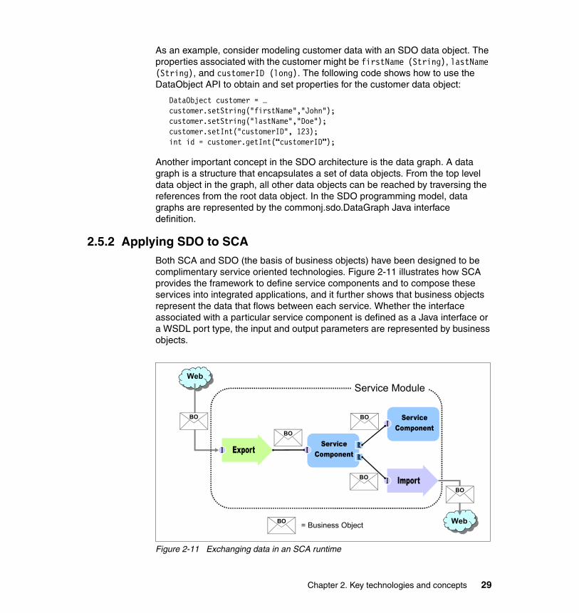
As an example, consider modeling customer data with an SDO data object. The properties associated with the customer might be firstName (String), lastName (String), and customerID (long). The following code shows how to use the DataObject API to obtain and set properties for the customer data object:
DataObject customer = …customer.setString("firstName","John");customer.setString("lastName","Doe");customer.setInt("customerID", 123);int id = customer.getInt(“customerID”);
Another important concept in the SDO architecture is the data graph. A data graph is a structure that encapsulates a set of data objects. From the top level data object in the graph, all other data objects can be reached by traversing the references from the root data object. In the SDO programming model, data graphs are represented by the commonj.sdo.DataGraph Java interface definition.
2.5.2 Applying SDO to SCABoth SCA and SDO (the basis of business objects) have been designed to be complimentary service oriented technologies. Figure 2-11 illustrates how SCA provides the framework to define service components and to compose these services into integrated applications, and it further shows that business objects represent the data that flows between each service. Whether the interface associated with a particular service component is defined as a Java interface or a WSDL port type, the input and output parameters are represented by business objects.
Figure 2-11 Exchanging data in an SCA runtime
Service Module
BO
BO BO
BO
BO
BO = Business Object
Web
Web
Chapter 2. Key technologies and concepts 29

30 Getting Started with WebSphere Enterprise Service Bus V6
Chapter 3. WebSphere Enterprise Service Bus overview and product positioning
This chapter gives a general product overview of WebSphere Enterprise Service Bus and related products. The products discussed here are:
� WebSphere Application Server V6.0� WebSphere Enterprise Service Bus V6.0� WebSphere Process Server V6.0� WebSphere MQ V6.0� WebSphere Message Broker V6.0� WebSphere Adapters V6.0� Rational Application Developer V6.0� WebSphere Integration Developer V6.0
Additionally, this chapter compares the ESB capabilities of WebSphere Enterprise Service Bus and WebSphere Message Broker to help you to determine which product might be appropriate in your situation.
3
© Copyright IBM Corp. 2006. All rights reserved. 31

3.1 Product overviewThis section provides an overview of the functions of WebSphere Enterprise Service Bus and other related WebSphere products.
The IBM SOA Reference Architecture defines the IT services required to support an SOA. It includes development environment, services management, application integration, and runtime process services. The capabilities of the architecture can be implemented on a build-as-you-go basis as new requirements are addressed over time.
Figure 3-1 shows the IBM SOA reference architecture and the supporting software.
Figure 3-1 IBM SOA Reference Architecture with product mapping
In this chapter, we concentrate on the two products that provide the ESB capabilities for an SOA and their related products:
� WebSphere Enterprise Service Bus provides ESB functions for SOAs built on open standards. It is based on WebSphere Application Server Network Deployment and inherits its built-in messaging provider and quality of services. WebSphere Process Server is built on top of WebSphere Enterprise Service Bus and adds a business process runtime.
� WebSphere Message Broker provides advanced ESB functionality for universal support of messaging applications. It is based on WebSphere MQ and takes advantage of the services that is provided by its messaging infrastructure.
Interaction ServicesWebSphere Portal
Server
Process ServicesWebSphere Process
Server
Information ServicesWebSphere
Information Integration
Partner ServicesWebSphere
Partner Gateway
Business App ServicesWebSphere
Application Server
Access ServicesWebSphere BusinessIntegration Adapters/
WebSphere Adapters/HATS
Infrastructure Services
WebSphere Enterprise Service Bus WebSphere Message BrokerESB
Rational Application Developer
WebSphere Integration Developer
WebSphere BusinessModeler
Business Innovation & Optimization ServicesWebSphere Business Monitor
IBM TivoliCompositeApplication
Manager
Dev
elop
men
tSe
rvic
es
IT S
ervi
ces
Man
agem
ent
32 Getting Started with WebSphere Enterprise Service Bus V6
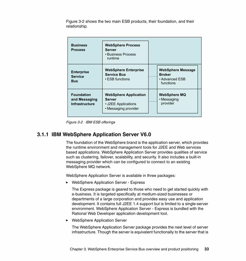
Figure 3-2 shows the two main ESB products, their foundation, and their relationship.
Figure 3-2 IBM ESB offerings
3.1.1 IBM WebSphere Application Server V6.0The foundation of the WebSphere brand is the application server, which provides the runtime environment and management tools for J2EE and Web services based applications. WebSphere Application Server provides qualities of service such as clustering, failover, scalability, and security. It also includes a built-in messaging provider which can be configured to connect to an existing WebSphere MQ network.
WebSphere Application Server is available in three packages:
� WebSphere Application Server - Express
The Express package is geared to those who need to get started quickly with e-business. It is targeted specifically at medium-sized businesses or departments of a large corporation and provides easy use and application development. It contains full J2EE 1.4 support but is limited to a single-server environment. WebSphere Application Server - Express is bundled with the Rational Web Developer application development tool.
� WebSphere Application Server
The WebSphere Application Server package provides the next level of server infrastructure. Though the server is equivalent functionally to the server that is
WebSphere ProcessServer• Business Processruntime
WebSphere EnterpriseService Bus• ESB functions
WebSphere ApplicationServer• J2EE Applications• Messaging provider
WebSphere MessageBroker• Advanced ESBfunctions
WebSphere MQ• Messagingprovider
BusinessProcess
EnterpriseServiceBus
Foundationand MessagingInfrastructure
Chapter 3. WebSphere Enterprise Service Bus overview and product positioning 33
shipped with Express, this package differs slightly in packaging and licensing. The development tool included is a trial version of Rational Application Developer, a fully J2EE 1.4 compliant development tool.
� WebSphere Application Server Network Deployment
WebSphere Application Server Network Deployment is an even higher level of server infrastructure in the WebSphere Application Server family. It extends the WebSphere Application Server base package to include clustering capabilities, Edge components, and high availability for distributed configurations. These features become more important at larger enterprises, where applications tend to service a larger customer base and more elaborate performance and availability requirements are in place.
WebSphere Application Server V6 provides full support for the J2EE 1.4 specification. The J2EE specification defines the concept of containers to provide runtime support for applications. There are three types of containers in the application server implementation:
� Web container
The Web container processes HTML, servlets, JSP™ files and other types of server-side includes. It provides infrastructure support such as Web container transport chains, session management, and Web services engine.
� EJB™ container
The EJB container provides all the runtime services that are needed to deploy and manage enterprise beans. Is is a server process that handles requests for both session and entity beans. The container provides low-level services, including threading and transaction support.
� Client container
The client container is a separately installed component on the client’s machine. It allows the client to run applications in an environment that is compatible with J2EE.
In addition to the definition of containers as a runtime environment for application components, the application server supports the following features that are prescribed by the J2EE:
� J2EE Connector Architecture
� Java Naming and Directory Interface™ (JNDI) name space
� Security: J2EE security, Java 2 security, JAAS
� JMS provider: WebSphere messaging (default messaging provider), WebSphere MQ JMS provider, generic JMS providers.
� Web services engine: WS-I Basic Profile, WS-Security, JAX-RPC, JAXR, SAAJ, UDDI.
34 Getting Started with WebSphere Enterprise Service Bus V6
With Network Deployment, clustering application servers automatically enables plug-in workload management for the application servers and the servlets they host. The routing is based on weights associated with the cluster members. If all cluster members have identical weights, the plug-in sends equal requests to all members of the cluster. Workload management for EJB containers can be performed by configuring the Web container and EJB containers on separate application servers. Multiple application servers with the EJB containers can be clustered, which enables the distribution of EJB requests between the EJB containers.
WebSphere Application Server Network Deployment also provides high availability features. The following is a quick overview of the failover capabilities:
� Web container failover
The Web server plug-in in the Web server is aware of the configuration of all Web containers and can route around a failed Web container in a cluster. Sessions can be persisted to a database or in-memory using data replication services.
� EJB container failover
Client code and the ORB plug-in can route to the next EJB container in the cluster.
� Critical services failover
Hot standby and peer failover for critical services (such as workload management routing, PMI aggregation, JMS messaging, transaction manager, and so on) is provided through the use of high availability domains. A high availability domain defines a set of WebSphere processes (core group) that provides high availability function to each other.
One or more members of the core group can act as a high availability coordinator, managing the high availability activities within the core group processes. If a high availability coordinator server fails, another server in the core group takes over the duties of that coordinator. High availability policies define how the failover occurs. Workload management information is shared between core members and failover of critical services is done among them in a peer-to-peer fashion. Little configuration is necessary, and in many cases, this function works with the defaults that are created automatically as you create the processes.
� JMS messaging failover
The messaging engine keeps messages in a remote database. When a server in a cluster fails, WebSphere selects an online server to run the messaging engine and the workload manager routes JMS connections to that server.
Chapter 3. WebSphere Enterprise Service Bus overview and product positioning 35
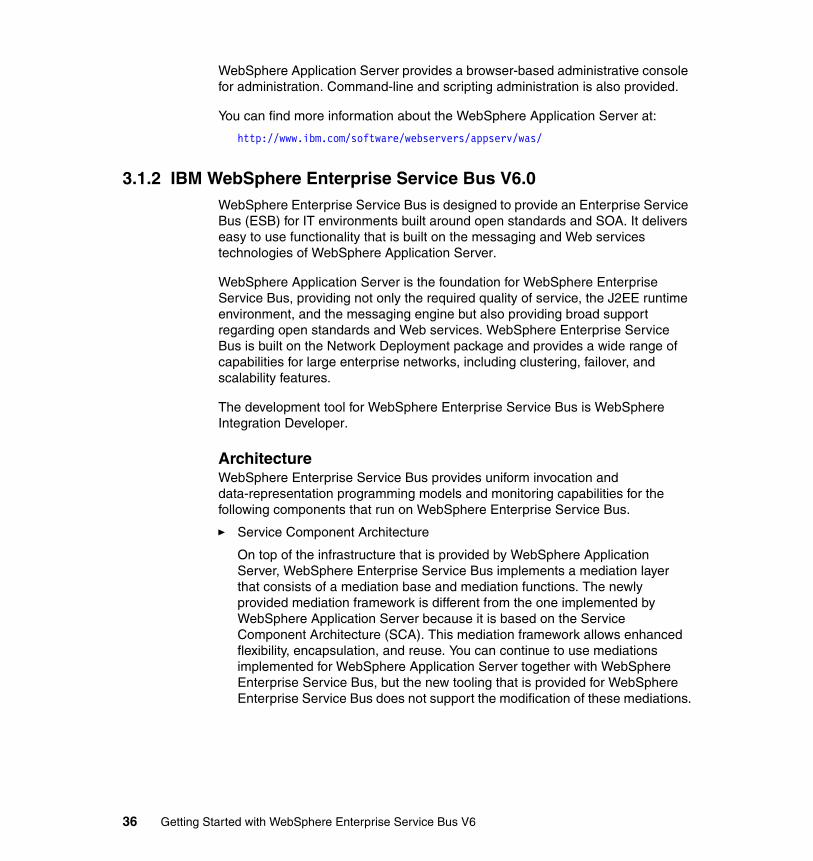
WebSphere Application Server provides a browser-based administrative console for administration. Command-line and scripting administration is also provided.
You can find more information about the WebSphere Application Server at:
http://www.ibm.com/software/webservers/appserv/was/
3.1.2 IBM WebSphere Enterprise Service Bus V6.0WebSphere Enterprise Service Bus is designed to provide an Enterprise Service Bus (ESB) for IT environments built around open standards and SOA. It delivers easy to use functionality that is built on the messaging and Web services technologies of WebSphere Application Server.
WebSphere Application Server is the foundation for WebSphere Enterprise Service Bus, providing not only the required quality of service, the J2EE runtime environment, and the messaging engine but also providing broad support regarding open standards and Web services. WebSphere Enterprise Service Bus is built on the Network Deployment package and provides a wide range of capabilities for large enterprise networks, including clustering, failover, and scalability features.
The development tool for WebSphere Enterprise Service Bus is WebSphere Integration Developer.
ArchitectureWebSphere Enterprise Service Bus provides uniform invocation and data-representation programming models and monitoring capabilities for the following components that run on WebSphere Enterprise Service Bus.
� Service Component Architecture
On top of the infrastructure that is provided by WebSphere Application Server, WebSphere Enterprise Service Bus implements a mediation layer that consists of a mediation base and mediation functions. The newly provided mediation framework is different from the one implemented by WebSphere Application Server because it is based on the Service Component Architecture (SCA). This mediation framework allows enhanced flexibility, encapsulation, and reuse. You can continue to use mediations implemented for WebSphere Application Server together with WebSphere Enterprise Service Bus, but the new tooling that is provided for WebSphere Enterprise Service Bus does not support the modification of these mediations.
36 Getting Started with WebSphere Enterprise Service Bus V6
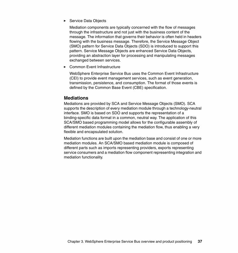
� Service Data Objects
Mediation components are typically concerned with the flow of messages through the infrastructure and not just with the business content of the message. The information that governs their behavior is often held in headers flowing with the business message. Therefore, the Service Message Object (SMO) pattern for Service Data Objects (SDO) is introduced to support this pattern. Service Message Objects are enhanced Service Data Objects, providing an abstraction layer for processing and manipulating messages exchanged between services.
� Common Event Infrastructure
WebSphere Enterprise Service Bus uses the Common Event Infrastructure (CEI) to provide event management services, such as event generation, transmission, persistence, and consumption. The format of those events is defined by the Common Base Event (CBE) specification.
MediationsMediations are provided by SCA and Service Message Objects (SMO). SCA supports the description of every mediation module through a technology-neutral interface. SMO is based on SDO and supports the representation of a binding-specific data format in a common, neutral way. The application of this SCA/SMO based programming model allows for the configurable assembly of different mediation modules containing the mediation flow, thus enabling a very flexible and encapsulated solution.
Mediation functions are built upon the mediation base and consist of one or more mediation modules. An SCA/SMO based mediation module is composed of different parts such as imports representing providers, exports representing service consumers and a mediation flow component representing integration and mediation functionality.
Chapter 3. WebSphere Enterprise Service Bus overview and product positioning 37
Figure 3-3 shows a mediation module acting on the flow of services requests between service consumers and providers.
Figure 3-3 WebSphere Enterprise Service Bus mediation module
WebSphere Enterprise Service Bus provides prebuilt components called mediation primitives that can be used in mediation flows to perform XSLT message transformation, logging, routing, and database lookup. It also supports the implementation of custom mediation primitives.
WebSphere Enterprise Service Bus supports different binding types for imports and exports, thus allowing the connection of different kinds of service consumers and providers. Supported binding types are JMS binding, Web services binding, WebSphere adapter binding, EJB binding, as well as SCA binding used for module to module communication.
The mediation framework and its mediation modules separate the processing of requests from the processing of replies. They allow the mediation flow components to pass a potentially modified request from a service consumer to a service provider and to pass a potentially modified reply from a service provider to a service consumer. The request processing within a mediation flow component can send a reply back to the consumer without necessarily needing to contact a service provider.
WebSphere Enterprise Service Bus
ServiceProvider
ServiceProvider
ServiceProvider
ServiceProvider
ServiceConsumer
ServiceConsumer
ServiceConsumer
Mediation Module
ImportsExport
38 Getting Started with WebSphere Enterprise Service Bus V6
Figure 3-4 shows a service consumer sending a request over the ESB. The ESB passes the request to the service provider. The service provider runs the service, then, optionally sends a reply to the consumer.
Figure 3-4 ESB passing request from consumer to provider
ClientsJ2EE clients from WebSphere Application Server Network Deployment, including Web services clients, EJB clients, and JMS clients can be used to extend connectivity of the ESB. Additionally WebSphere Enterprise Service Bus provides Message Service Clients for C/C++ and .NET, Web services clients for C++, and SCA clients for Java.
WebSphere Enterprise Service Bus
ServiceProvider
ServiceProvider
ServiceProvider
ServiceProvider
ServiceConsumer
ServiceConsumer
ServiceConsumer Reply
(optional)
Request
Chapter 3. WebSphere Enterprise Service Bus overview and product positioning 39
You can find more information about the WebSphere Enterprise Service Bus at:
http://www.ibm.com/software/integration/wsesb/
Mediation functions in WebSphere Enterprise Service Bus versus WebSphere Application Server
Before the announcement of WebSphere Enterprise Service Bus, the service integration bus in WebSphere Application Server was often positioned as a basic ESB. Although this is still a useful strategy for development environments, WebSphere Enterprise Service Bus is now the recommended solution for environments where the service integration bus was used.
WebSphere Enterprise Service Bus adds the following functionality to the service integration bus.
� Easy to build mediation layer� Simplified administration� Pre-built mediation functions� Broad connectivity
Mediation functions in WebSphere Enterprise Service Bus are service intermediaries that:
� Operate on interactions between service endpoints (consumer and provider)
� Are administered as part of WebSphere Enterprise Service Bus
� Are created using visual tooling exploiting supplied and custom mediation functions
� Have access to binding specific header data like SOAP and JMS headers
Mediation handlers in the WebSphere Application Server service integration bus are message handlers that:
� Operate on messages traversing the bus � Are administered as part of the bus� Are created by implementing Java programs� Allow access to the full WebSphere messaging header information
40 Getting Started with WebSphere Enterprise Service Bus V6
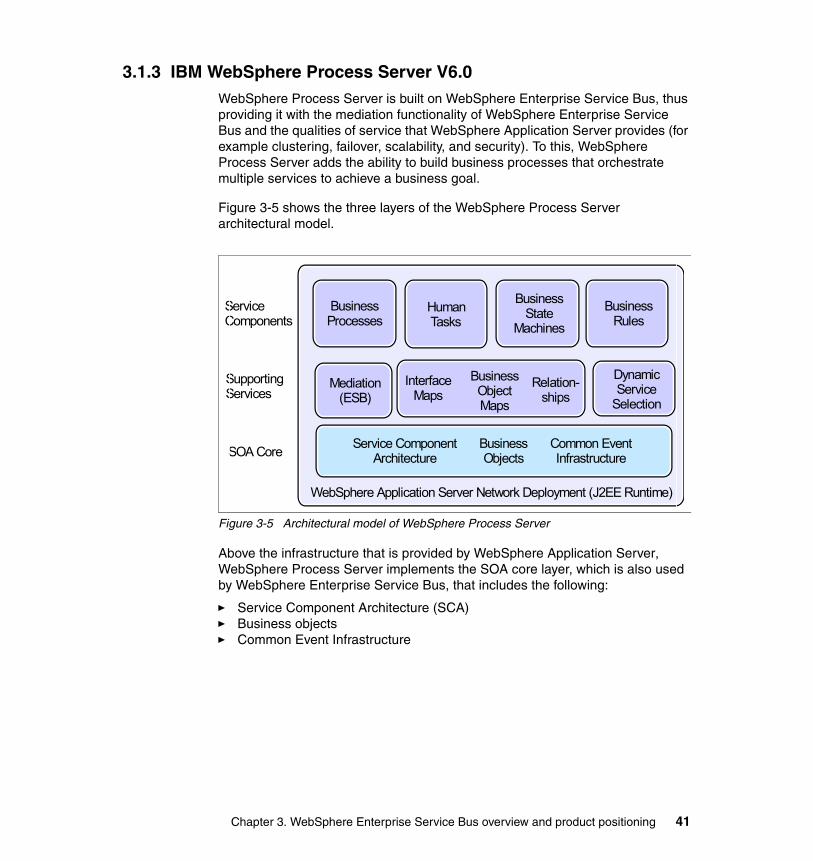
3.1.3 IBM WebSphere Process Server V6.0WebSphere Process Server is built on WebSphere Enterprise Service Bus, thus providing it with the mediation functionality of WebSphere Enterprise Service Bus and the qualities of service that WebSphere Application Server provides (for example clustering, failover, scalability, and security). To this, WebSphere Process Server adds the ability to build business processes that orchestrate multiple services to achieve a business goal.
Figure 3-5 shows the three layers of the WebSphere Process Server architectural model.
Figure 3-5 Architectural model of WebSphere Process Server
Above the infrastructure that is provided by WebSphere Application Server, WebSphere Process Server implements the SOA core layer, which is also used by WebSphere Enterprise Service Bus, that includes the following:
� Service Component Architecture (SCA)� Business objects� Common Event Infrastructure
Service ComponentArchitecture
WebSphere Application Server Network Deployment (J2EE Runtime)
BusinessObjects
Common EventInfrastructure
BusinessState
Machines
BusinessProcesses
HumanTasks
BusinessRules
InterfaceMaps
BusinessObject Maps
Relation- ships
ServiceComponents
SupportingServices
SOA Core
Mediation (ESB)
Dynamic Service
Selection
Chapter 3. WebSphere Enterprise Service Bus overview and product positioning 41
On top of this SOA Core layer lies the service components and supporting services layers. WebSphere Process Server implements a number of components and services that can be used in an integration solution. In the service components layer, you find the following:
� Business processes
The business process component in WebSphere Process Server implements a WS-BPEL compliant process engine.
� Human tasks
Human tasks in WebSphere Process Server are stand-alone components which can be used to assign work to employees or to invoke any other service.
� Business state machines
A business state machine provides another way of modeling a business process. This enables businesses to represent their business processes based on states and events.
� Business rules
Business rules are a means of implementing and enforcing business policy through externalizing of business function. This enables dynamic changes of a business process.
These components can use the features of a number of supporting services in WebSphere Process Server. Most of these can be classified as some form of transformation. There are a number of transformation challenges when connecting components and external services, each of which is being addressed by a component of WebSphere Process Server:
� Interface maps
Very often interfaces of existing components match semantically but not syntactically. Interface maps allow the invocation of these components by translating these calls. Additionally business object maps can be used to translate the actual business object parameters of a service invocation.
� Business object maps
A business object map is used to translate one type of business object into another type of business object.
� Relationships
In business integration scenarios it is often necessary to access the same data in various backend systems for example an ERP system and a CRM system. A common problem for keeping business objects in sync is that different backend systems use different keys to represent the same objects. The relationship service in WebSphere Process Server can be used to
42 Getting Started with WebSphere Enterprise Service Bus V6
establish relationship instances between objects in these disparate backend systems. These relationships are accessed from a business object map when translating one business object format into another.
� Dynamic service selection
A selector component allows dynamic selection and invocation of different services, which all share the same interface.
� Mediation
This component is inherited from WebSphere Enterprise Service Bus.
The primary development tool for WebSphere Process Server is WebSphere Integration Developer. This is the same tool used for WebSphere Enterprise Service Bus development tasks.
You can find more information about IBM WebSphere Process Server V6 at:
http://www.ibm.com/software/integration/wps/
3.1.4 IBM WebSphere MQ V6.0IBM WebSphere MQ is an established and reliable message queuing middleware platform. A message queuing infrastructure built upon WebSphere MQ technology can provide an available, reliable, scalable, secure, and maintainable transport for messages with delivery assurance.
The Message Queuing Interface (MQI) is the core API that is provided by WebSphere MQ. It is a procedural API suitable for applications developed within procedural programming languages. Procedural languages like C and COBOL most likely utilize MQI directly while object oriented languages like Java and C++ are supported with object oriented APIs built upon MQI.
WebSphere MQ also supports Java Message Service (JMS) and WebSphere message client API (XMS), a programming API that allows access from C, C++, and .NET applications.
WebSphere MQ provides features to assure security of access, authentication of identity and security and integrity of communication. The Object Authority Manager (OAM) is the default authorization service for command and object management. All actions performed by an application connected to a queue manager, are authenticated by the OAM.
WebSphere MQ provides high availability through workload balancing and failover capabilities. Administration of WebSphere MQ is typically done using control commands or the Eclipse-based WebSphere MQ Explorer administration tool (Windows® or Linux® only).
Chapter 3. WebSphere Enterprise Service Bus overview and product positioning 43
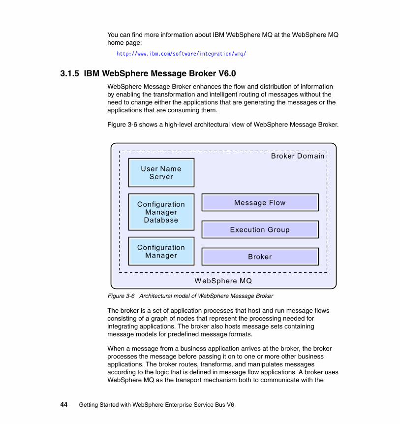
You can find more information about IBM WebSphere MQ at the WebSphere MQ home page:
http://www.ibm.com/software/integration/wmq/
3.1.5 IBM WebSphere Message Broker V6.0WebSphere Message Broker enhances the flow and distribution of information by enabling the transformation and intelligent routing of messages without the need to change either the applications that are generating the messages or the applications that are consuming them.
Figure 3-6 shows a high-level architectural view of WebSphere Message Broker.
Figure 3-6 Architectural model of WebSphere Message Broker
The broker is a set of application processes that host and run message flows consisting of a graph of nodes that represent the processing needed for integrating applications. The broker also hosts message sets containing message models for predefined message formats.
When a message from a business application arrives at the broker, the broker processes the message before passing it on to one or more other business applications. The broker routes, transforms, and manipulates messages according to the logic that is defined in message flow applications. A broker uses WebSphere MQ as the transport mechanism both to communicate with the
ConfigurationManager
W ebSphere MQ
ConfigurationManagerDatabase
User NameServer
Broker
Execution Group
Message Flow
Broker Domain
44 Getting Started with WebSphere Enterprise Service Bus V6
Configuration Manager, from which it receives configuration information, and to communicate with any other brokers to which it is associated. Each broker has a database in which it stores the information that it needs to process messages at run time.
Execution groups enable message flows within the broker to be grouped together. Each broker contains a default execution group. You can create additional execution groups as long as they have unique names within the broker. Each execution group is a separate operating system process and, therefore, the contents of an execution group remain separate from the contents of other execution groups within the same broker. This design can be useful for isolating pieces of information for security because the message flows execute in separate address spaces or as unique processes. Message flow applications are deployed to a specific execution group. To enhance performance, the same message flows and message sets can be running in different execution groups.
The Configuration Manager is the interface between the Message Brokers Toolkit and the brokers in the broker domain. The Configuration Manager stores configuration details for the broker domain in an internal repository, providing a central store for resources in the broker domain. The Configuration Manager is responsible for deploying message flow applications to the brokers and delivering reports on the progress of the deployment and on the status of the broker. When the Message Brokers Toolkit connects to the Configuration Manager, the status of the brokers in the domain is derived from the configuration information stored in the Configuration Manager’s internal repository.
WebSphere Message Broker together with WebSphere MQ provide high availability features. This is quite important because WebSphere Message Broker acts as a hub and therefore needs to be eliminated as a single point of failure.
Load balancing and high availability can be achieved by providing multiple broker instances serving the same logical hub with each instance is mapped to its own WebSphere MQ queue manager. The different broker instances could reside on different machines.
WebSphere Message Broker provides the Message Broker Toolkit, a graphical environment for developing and deploying message flow applications.
You can find more information about IBM WebSphere Message Broker at the WebSphere Message Broker home page:
http://www.ibm.com/software/integration/wbimessagebroker/v6/
Chapter 3. WebSphere Enterprise Service Bus overview and product positioning 45
3.1.6 IBM WebSphere Adapters V6.0Not all applications provide a Web service or messaging interface. In these instances, adapters can be used to link applications to the ESB. WebSphere Adapters are compliant to the Java 2 Platform, Enterprise Edition Connector Architecture version 1.5. They enable inbound and outbound connectivity between enterprise information systems and SCA based applications hosted by WebSphere Enterprise Service Bus or WebSphere Process Server. The WebSphere Adapters are deployed as part of an J2EE application as an embedded resource adapter.
IBM also offers WebSphere Business Integration Adapters. These adapters are not standard based and reside outside of the application server. The server communicates with these adapters uses a JMS transport layer.
3.2 Enterprise Service Bus product positioningThe product you select to implement an ESB depends on the requirements of your solution. We introduce two strategic products that provide ESB capabilities:
� WebSphere Enterprise Service Bus� WebSphere Message Broker
Now, we give a quick comparison of the two products.
WebSphere Enterprise Service Bus is designed to provide the core functionality of an ESB for a predominantly Web services based environment. It is built on WebSphere Application Server, which provides the foundation for the transport layer. WebSphere Enterprise Service Bus adds a mediation layer based on the SCA programming model on top of this foundation to provide intelligent connectivity. If the customer has a lot of Web services in their environment, WebSphere Enterprise Service Bus is likely to be the better product to use.
WebSphere Message Broker provides a more advanced ESB solution with advanced integration capabilities such as universal connectivity and any-to-any transformation for data-centric deployments. It can handle services integration as well as integration with non-services applications. WebSphere MQ provides the transport backbone for messaging applications. Typically, customers who need a higher performance and throughput product in a message-centric environment would use WebSphere Message Broker.
46 Getting Started with WebSphere Enterprise Service Bus V6
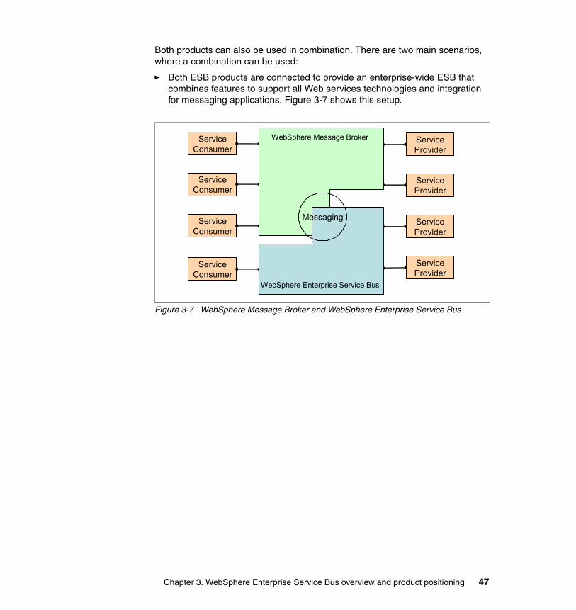
Both products can also be used in combination. There are two main scenarios, where a combination can be used:
� Both ESB products are connected to provide an enterprise-wide ESB that combines features to support all Web services technologies and integration for messaging applications. Figure 3-7 shows this setup.
Figure 3-7 WebSphere Message Broker and WebSphere Enterprise Service Bus
ServiceProvider
ServiceProvider
ServiceProvider
ServiceProvider
ServiceConsumer
ServiceConsumer
ServiceConsumer
ServiceConsumer
WebSphere Enterprise Service Bus
WebSphere Message Broker
Messaging
Chapter 3. WebSphere Enterprise Service Bus overview and product positioning 47
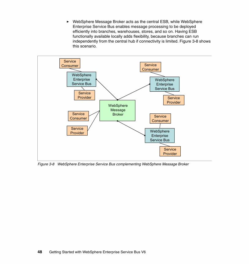
� WebSphere Message Broker acts as the central ESB, while WebSphere Enterprise Service Bus enables message processing to be deployed efficiently into branches, warehouses, stores, and so on. Having ESB functionally available locally adds flexibility, because branches can run independently from the central hub if connectivity is limited. Figure 3-8 shows this scenario.
Figure 3-8 WebSphere Enterprise Service Bus complementing WebSphere Message Broker
ServiceConsumer
WebSphereMessageBroker
WebSphereEnterprise
Service Bus
WebSphereEnterprise
Service Bus
WebSphereEnterprise
Service Bus
ServiceConsumer Service
Consumer
ServiceConsumer
ServiceProvider Service
Provider
ServiceProvider
ServiceProvider
48 Getting Started with WebSphere Enterprise Service Bus V6
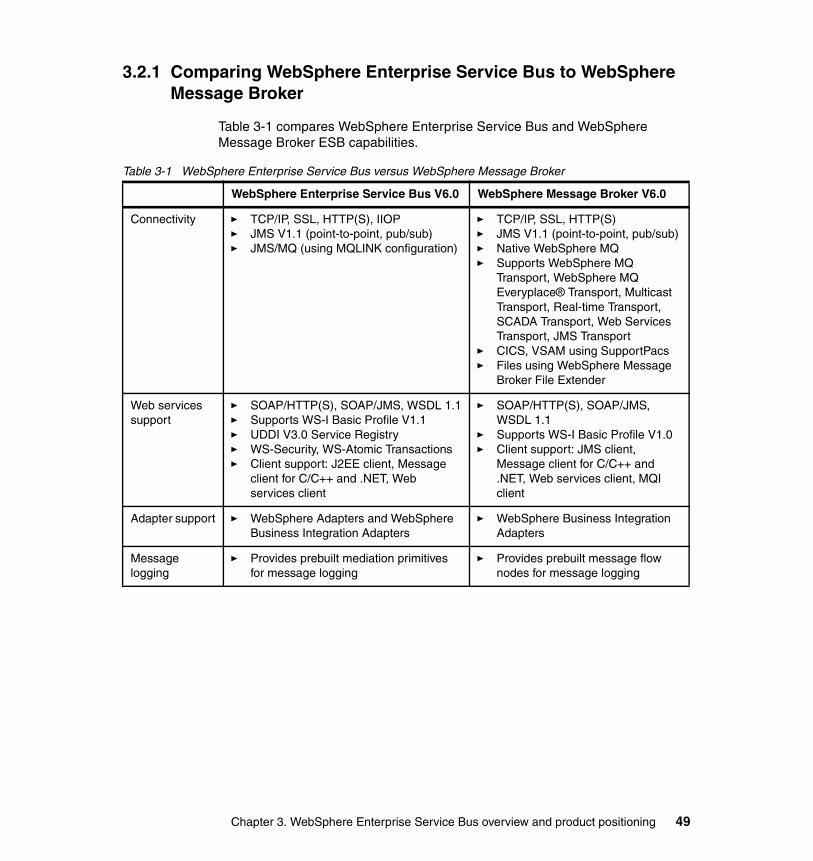
3.2.1 Comparing WebSphere Enterprise Service Bus to WebSphere Message Broker
Table 3-1 compares WebSphere Enterprise Service Bus and WebSphere Message Broker ESB capabilities.
Table 3-1 WebSphere Enterprise Service Bus versus WebSphere Message Broker
WebSphere Enterprise Service Bus V6.0 WebSphere Message Broker V6.0
Connectivity � TCP/IP, SSL, HTTP(S), IIOP� JMS V1.1 (point-to-point, pub/sub)� JMS/MQ (using MQLINK configuration)
� TCP/IP, SSL, HTTP(S)� JMS V1.1 (point-to-point, pub/sub)� Native WebSphere MQ� Supports WebSphere MQ
Transport, WebSphere MQ Everyplace® Transport, Multicast Transport, Real-time Transport, SCADA Transport, Web Services Transport, JMS Transport
� CICS, VSAM using SupportPacs� Files using WebSphere Message
Broker File Extender
Web services support
� SOAP/HTTP(S), SOAP/JMS, WSDL 1.1� Supports WS-I Basic Profile V1.1� UDDI V3.0 Service Registry� WS-Security, WS-Atomic Transactions� Client support: J2EE client, Message
client for C/C++ and .NET, Web services client
� SOAP/HTTP(S), SOAP/JMS, WSDL 1.1
� Supports WS-I Basic Profile V1.0� Client support: JMS client,
Message client for C/C++ and .NET, Web services client, MQI client
Adapter support � WebSphere Adapters and WebSphere Business Integration Adapters
� WebSphere Business Integration Adapters
Message logging
� Provides prebuilt mediation primitives for message logging
� Provides prebuilt message flow nodes for message logging
Chapter 3. WebSphere Enterprise Service Bus overview and product positioning 49
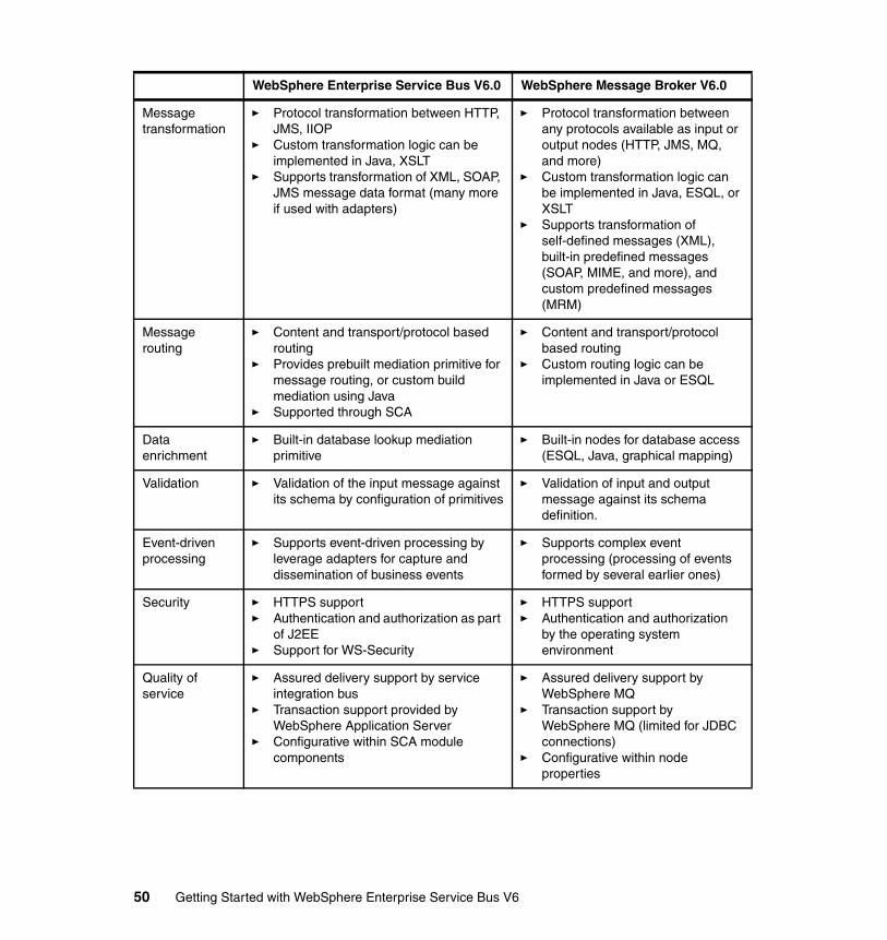
Message transformation
� Protocol transformation between HTTP, JMS, IIOP
� Custom transformation logic can be implemented in Java, XSLT
� Supports transformation of XML, SOAP, JMS message data format (many more if used with adapters)
� Protocol transformation between any protocols available as input or output nodes (HTTP, JMS, MQ, and more)
� Custom transformation logic can be implemented in Java, ESQL, or XSLT
� Supports transformation of self-defined messages (XML), built-in predefined messages (SOAP, MIME, and more), and custom predefined messages (MRM)
Message routing
� Content and transport/protocol based routing
� Provides prebuilt mediation primitive for message routing, or custom build mediation using Java
� Supported through SCA
� Content and transport/protocol based routing
� Custom routing logic can be implemented in Java or ESQL
Data enrichment
� Built-in database lookup mediation primitive
� Built-in nodes for database access (ESQL, Java, graphical mapping)
Validation � Validation of the input message against its schema by configuration of primitives
� Validation of input and output message against its schema definition.
Event-driven processing
� Supports event-driven processing by leverage adapters for capture and dissemination of business events
� Supports complex event processing (processing of events formed by several earlier ones)
Security � HTTPS support� Authentication and authorization as part
of J2EE� Support for WS-Security
� HTTPS support� Authentication and authorization
by the operating system environment
Quality of service
� Assured delivery support by service integration bus
� Transaction support provided by WebSphere Application Server
� Configurative within SCA module components
� Assured delivery support by WebSphere MQ
� Transaction support by WebSphere MQ (limited for JDBC connections)
� Configurative within node properties
WebSphere Enterprise Service Bus V6.0 WebSphere Message Broker V6.0
50 Getting Started with WebSphere Enterprise Service Bus V6
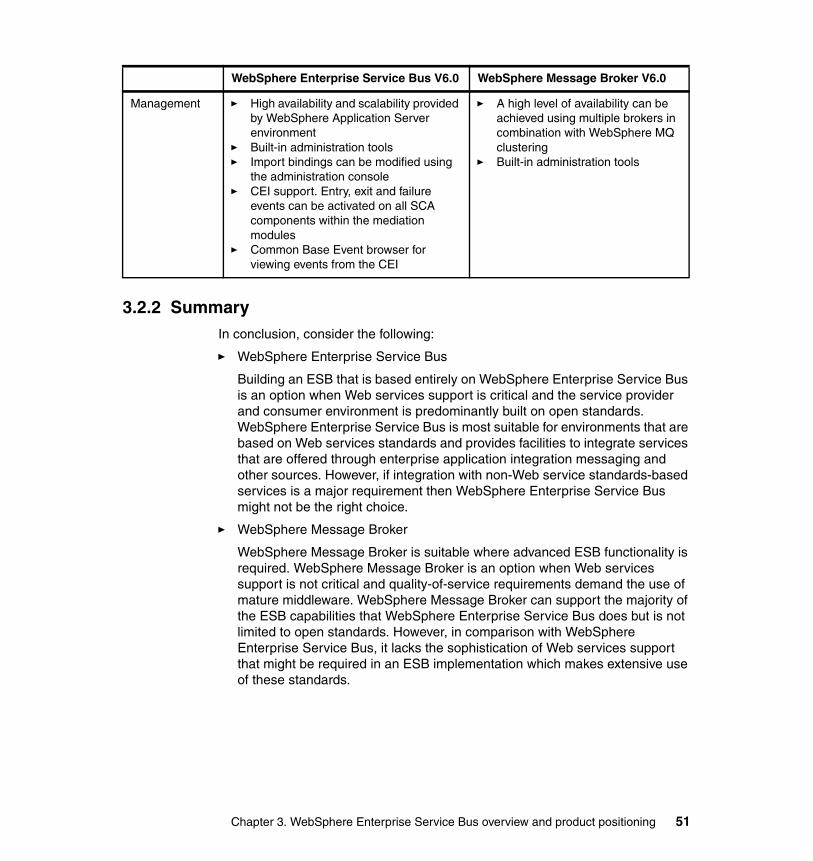
3.2.2 SummaryIn conclusion, consider the following:
� WebSphere Enterprise Service Bus
Building an ESB that is based entirely on WebSphere Enterprise Service Bus is an option when Web services support is critical and the service provider and consumer environment is predominantly built on open standards. WebSphere Enterprise Service Bus is most suitable for environments that are based on Web services standards and provides facilities to integrate services that are offered through enterprise application integration messaging and other sources. However, if integration with non-Web service standards-based services is a major requirement then WebSphere Enterprise Service Bus might not be the right choice.
� WebSphere Message Broker
WebSphere Message Broker is suitable where advanced ESB functionality is required. WebSphere Message Broker is an option when Web services support is not critical and quality-of-service requirements demand the use of mature middleware. WebSphere Message Broker can support the majority of the ESB capabilities that WebSphere Enterprise Service Bus does but is not limited to open standards. However, in comparison with WebSphere Enterprise Service Bus, it lacks the sophistication of Web services support that might be required in an ESB implementation which makes extensive use of these standards.
Management � High availability and scalability provided by WebSphere Application Server environment
� Built-in administration tools� Import bindings can be modified using
the administration console� CEI support. Entry, exit and failure
events can be activated on all SCA components within the mediation modules
� Common Base Event browser for viewing events from the CEI
� A high level of availability can be achieved using multiple brokers in combination with WebSphere MQ clustering
� Built-in administration tools
WebSphere Enterprise Service Bus V6.0 WebSphere Message Broker V6.0
Chapter 3. WebSphere Enterprise Service Bus overview and product positioning 51
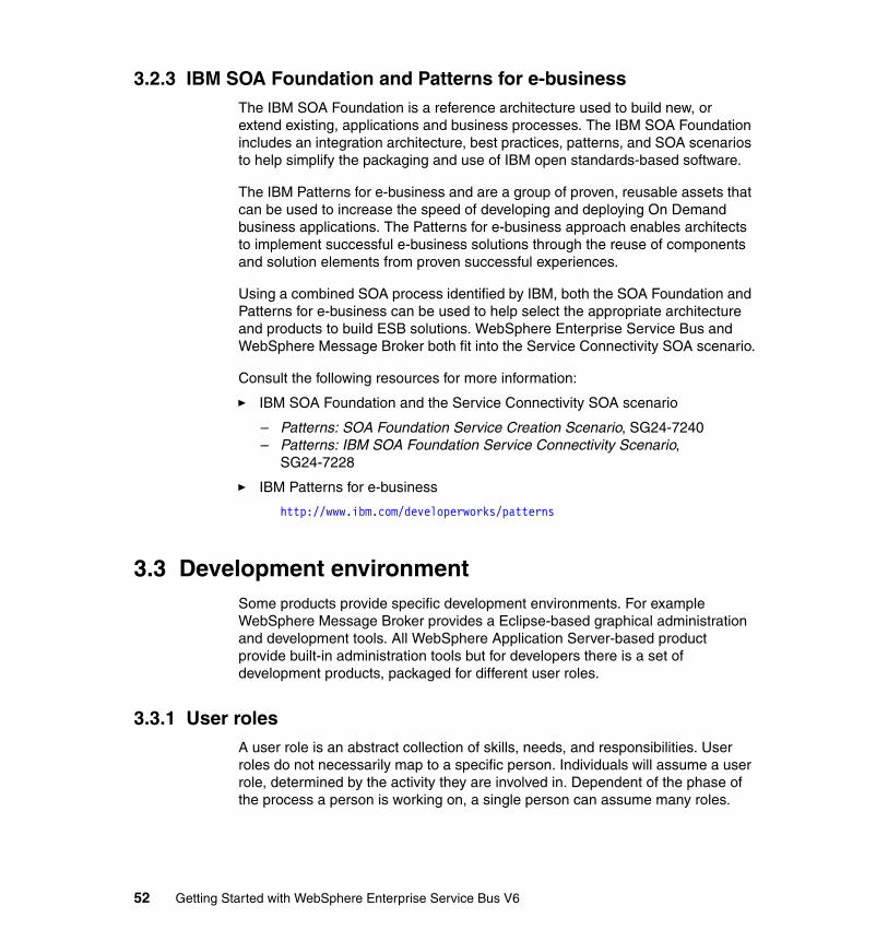
3.2.3 IBM SOA Foundation and Patterns for e-businessThe IBM SOA Foundation is a reference architecture used to build new, or extend existing, applications and business processes. The IBM SOA Foundation includes an integration architecture, best practices, patterns, and SOA scenarios to help simplify the packaging and use of IBM open standards-based software.
The IBM Patterns for e-business and are a group of proven, reusable assets that can be used to increase the speed of developing and deploying On Demand business applications. The Patterns for e-business approach enables architects to implement successful e-business solutions through the reuse of components and solution elements from proven successful experiences.
Using a combined SOA process identified by IBM, both the SOA Foundation and Patterns for e-business can be used to help select the appropriate architecture and products to build ESB solutions. WebSphere Enterprise Service Bus and WebSphere Message Broker both fit into the Service Connectivity SOA scenario.
Consult the following resources for more information:
� IBM SOA Foundation and the Service Connectivity SOA scenario
– Patterns: SOA Foundation Service Creation Scenario, SG24-7240– Patterns: IBM SOA Foundation Service Connectivity Scenario,
SG24-7228
� IBM Patterns for e-business
http://www.ibm.com/developerworks/patterns
3.3 Development environmentSome products provide specific development environments. For example WebSphere Message Broker provides a Eclipse-based graphical administration and development tools. All WebSphere Application Server-based product provide built-in administration tools but for developers there is a set of development products, packaged for different user roles.
3.3.1 User rolesA user role is an abstract collection of skills, needs, and responsibilities. User roles do not necessarily map to a specific person. Individuals will assume a user role, determined by the activity they are involved in. Dependent of the phase of the process a person is working on, a single person can assume many roles.
52 Getting Started with WebSphere Enterprise Service Bus V6
For the life cycle of an SOA, the ESB user roles are shown in Figure 3-9.
Figure 3-9 SOA life cycle role mapping
The line of business manager and the business analyst are responsible for modeling the solution. While the line of business manager is concentrating on the strategy, the business analyst models the solution that supports the strategy. The integration developer and the application developer assemble the solution and work together with the administrators and deployers to deploy the solution. Then the administrators are responsible for managing the solution.
Here, we concentrate on the two roles involved in the assembly phase:
� Integration developer
The integration developer focuses on the SOA solutions. This role needs some programming experience, but expects the tools to simplify and abstract advanced implementation details. This role develops SCA-based applications, such as mediation modules, using existing components.
The integration developer uses WebSphere Integration Developer for all the tasks in this role.
� Application developer
The application developer focuses on development of components and services used by the SOA solution. This includes developing Web services, resource adapters, and custom mediations.
The application developer uses Rational Application Developer for development.
Model Assemble Deploy Manage
• Business Analyst
• Line of Business Managers
• IntegrationDeveloper
• ApplicationDeveloper
• ServerAdministrator
• SolutionAdministrator
• SolutionDeployer
• IntegrationDeveloper
• ApplicationDeveloper
• ServerAdministrator
• SolutionAdministrator
Chapter 3. WebSphere Enterprise Service Bus overview and product positioning 53
3.3.2 Rational Application Developer V6.0For J2EE application developers IBM offers Rational Application Developer for WebSphere software. It is based on the Rational Software Development Platform. It includes all features of Rational Web Developer included in WebSphere Application Server - Express and additionally provides EJB and Web service development tools. So all components to be deployed to WebSphere Application Server and WebSphere Application Server Network Deployment can be developed using Rational Application Developer.
For developers using modeling language technologies for creating Java and service-oriented applications, Rational Software Architect adds modeling features to the functions available in Rational Application Developer.
3.3.3 WebSphere Integration Developer V6.0In WebSphere Integration Developer the integration developer can create all components to be deployed to WebSphere Enterprise Service Bus and WebSphere Process Server.
WebSphere Integration Developer provides editors to work on SCA modules, interfaces, data types, and all kinds of SCA components. It also supports integrated debugging for modules and components, a unit test environment, and a end-to-end framework.
WebSphere Integration Developer supports the top-down and the bottom-up development approach. It is designed to hide the complexity of WSDL, XSD, XPath and XSLT. So integration developers do not need to have deep skills in these technologies to create a solution. Wherever the supplied mediation primitives do not meet the needs, custom mediation primitives can be created visually or by writing Java code. These more advanced task are typically performed by more advanced integration developers or application developers.
54 Getting Started with WebSphere Enterprise Service Bus V6
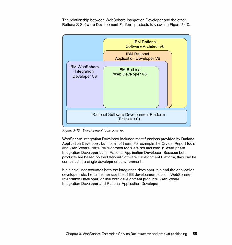
The relationship between WebSphere Integration Developer and the other Rational® Software Development Platform products is shown in Figure 3-10.
Figure 3-10 Development tools overview
WebSphere Integration Developer includes most functions provided by Rational Application Developer, but not all of them. For example the Crystal Report tools and WebSphere Portal development tools are not included in WebSphere Integration Developer but in Rational Application Developer. Because both products are based on the Rational Software Development Platform, they can be combined in a single development environment.
If a single user assumes both the integration developer role and the application developer role, he can either use the J2EE development tools in WebSphere Integration Developer, or use both development products, WebSphere Integration Developer and Rational Application Developer.
IBM RationalSoftware Architect V6
IBM RationalApplication Developer V6
IBM RationalWeb Developer V6
Rational Software Development Platform(Eclipse 3.0)
IBM WebSphereIntegration
Developer V6
Chapter 3. WebSphere Enterprise Service Bus overview and product positioning 55

56 Getting Started with WebSphere Enterprise Service Bus V6
Part 2 Configuration and usage
Part 2
© Copyright IBM Corp. 2006. All rights reserved. 57

58 Getting Started with WebSphere Enterprise Service Bus V6

Chapter 4. Setting up the development environment
This chapter discusses the WebSphere Enterprise Service Bus development environment, WebSphere Integration Developer V6.0.1. It discusses the following topics:
� Overview of development environment� Planning for multiple development environments� Installing the development environment� Team development� Integration test considerations� Troubleshooting installation issues
4
© Copyright IBM Corp. 2006. All rights reserved. 59
4.1 Overview of development environmentWebSphere Integration Developer V6.0.1 is the development environment for WebSphere Enterprise Service Bus V6.0 and WebSphere Process Server V6.0.1. It provides an environment for building and testing integrated applications based on a services-oriented architecture.
The application development in WebSphere Integration Developer V6.0.1 is based on Service Component Architecture. Besides developing Service Component Architecture components and modules, WebSphere Integration Developer is also used to assemble mediations, components using mediation primitives, and to create mediation modules. WebSphere Integration Developer includes an integrated unit test environment for WebSphere Process Server and WebSphere Enterprise Service Bus, allowing developers to deploy their modules to the integrated test server and perform unit testing using the integration test client.
4.1.1 Hardware and software requirementsThe WebSphere Integration Developer product Web site provides the list of minimum hardware and software required. You can find this information at:
http://www.ibm.com/software/integration/wid/sysreqs
4.1.2 Consider your current environmentWebSphere Integration Developer is based on Rational Software Development Platform which is shared by several IBM products. You can find the list of IBM products that are based on Rational Software Development Platform at:
http://publib.boulder.ibm.com/infocenter/dmndhelp/v6rxmx/index.jsp?topic=/com.ibm.wbit.help.install.doc/topics/cinsdp.html
If your current environment has any existing Rational Software Development Platform products installed, the installation of WebSphere Integration Developer integrates into the existing Rational Software Development Platform.
WebSphere Integration Developer V6.0.1 is based on Rational Software Development Platform V6.0.1 and is only compatible with other products that are based on this level. If you have a product that uses an earlier version of Rational
Note: Rational Software Development Platform is installed only once when the first product is installed. Subsequent products use the common user interface and add product specific functionality that is provided by the plug-ins.
60 Getting Started with WebSphere Enterprise Service Bus V6
Software Development Platform, you are required to upgrade that product or uninstall it, so that you can install WebSphere Integration Developer V6.0.1.
WebSphere Integration Developer can coexist with WebSphere Studio Application Developer Integration Edition V5.1.1 and previous releases. WebSphere Integration Developer V6.0.1 cannot coexist with WebSphere Integration Developer V6.0.
4.2 Planning for multiple development environmentsWhen setting up multiple WebSphere Integration Developer environments, ensure that each developer workstation has sufficient disk space for the installation. WebSphere Integration Developer installation requires about 5.5 GB of disk space for the installation directory as well as 1 GB of disk space for temporary files.
While it might be convenient to install on multiple workstations from a network installation image, due to the size of the installation image, it is recommended that the installation image be copied to the local drive of the workstation before starting the WebSphere Integration Developer installation. This will ensure the installation completes successfully, and does not get affected by network issues.
You can find information about creating a network installation image at:
http://publib.boulder.ibm.com/infocenter/dmndhelp/v6rxmx/index.jsp?topic=/com.ibm.wbit.help.install.doc/topics/tinstnet.html
When installing on Windows operating systems, WebSphere Integration Developer by default gets installed in C:\Program Files\IBM\WebSphere\ID\6.0. Its recommended the installation directory be changed to a short fully qualified directory name to avoid problems with path length exceeding 256 characters on Windows. When setting up multiple development environment, it helps to use a standard directory name for the installation for ease of management.
4.2.1 Silent installationInstead of using the installation wizard, it is possible to install WebSphere Integration Developer non-interactively, using a response file. Silent installation could be very useful when setting up multiple development environments.
Note: Installing WebSphere Integration Developer silently using the provided response file installs the default features. It installs the Integrated Development Environment and does not install the Integrated Test Environment.
Chapter 4. Setting up the development environment 61
Prior to performing a silent installation, you must:
1. Configure the response file used for the installation.2. Check the workstation for any issues related to co-existence or upgrade.3. Ensure the workstation has sufficient disk space for the installation.
The sample response file is called responsefile.txt and is in the \disk1\util directory. Based on your development environment requirements, it is recommended that you make a copy of the response file and modify it accordingly.
If your developers intend to work mainly on developing mediation flow components and test only applications created by the mediation flow editor, you can modify the response file and select WebSphere Enterprise Service Bus server only as the unit test server for the installation and do not have to install WebSphere Process Server.
You can find information about configuring the response file and starting a silent installation at:
http://publib.boulder.ibm.com/infocenter/dmndhelp/v6rxmx/index.jsp?topic=/com.ibm.wbit.help.install.doc/topics/thushadditional.html
4.2.2 RolesWebSphere Integration Developer supports several user roles for different activities and functionality. WebSphere Integration Developer hides product features based on the role selected. A specific user role can be enabled or disabled from the Welcome page on WebSphere Integration Developer. The hidden features can be enabled when first accessed or through Window → Preferences → Workbench → Capabilities. Integration Developer is primary role used for developing mediation modules and build SOA solutions.
For more information about user roles, see 3.3.1, “User roles” on page 52.
4.3 Installing the development environmentThis section describes how to install WebSphere Integration Developer and essential product updates. It assumes a Windows environment. It discusses the following topics:
� Installing WebSphere Integration Developer� Using Rational Product Updater� Starting WebSphere Integration Developer
62 Getting Started with WebSphere Enterprise Service Bus V6
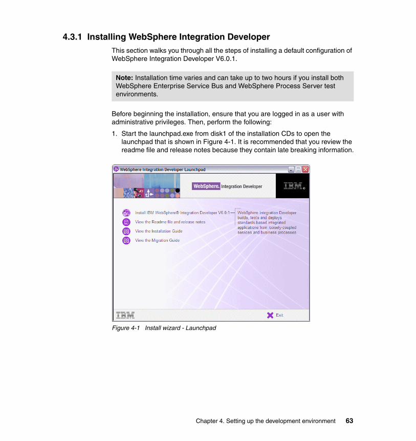
4.3.1 Installing WebSphere Integration DeveloperThis section walks you through all the steps of installing a default configuration of WebSphere Integration Developer V6.0.1.
Before beginning the installation, ensure that you are logged in as a user with administrative privileges. Then, perform the following:
1. Start the launchpad.exe from disk1 of the installation CDs to open the launchpad that is shown in Figure 4-1. It is recommended that you review the readme file and release notes because they contain late breaking information.
Figure 4-1 Install wizard - Launchpad
Note: Installation time varies and can take up to two hours if you install both WebSphere Enterprise Service Bus and WebSphere Process Server test environments.
Chapter 4. Setting up the development environment 63
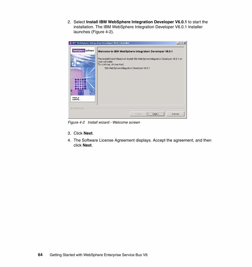
2. Select Install IBM WebSphere Integration Developer V6.0.1 to start the installation. The IBM WebSphere Integration Developer V6.0.1 Installer launches (Figure 4-2).
Figure 4-2 Install wizard - Welcome screen
3. Click Next.
4. The Software License Agreement displays. Accept the agreement, and then click Next.
64 Getting Started with WebSphere Enterprise Service Bus V6
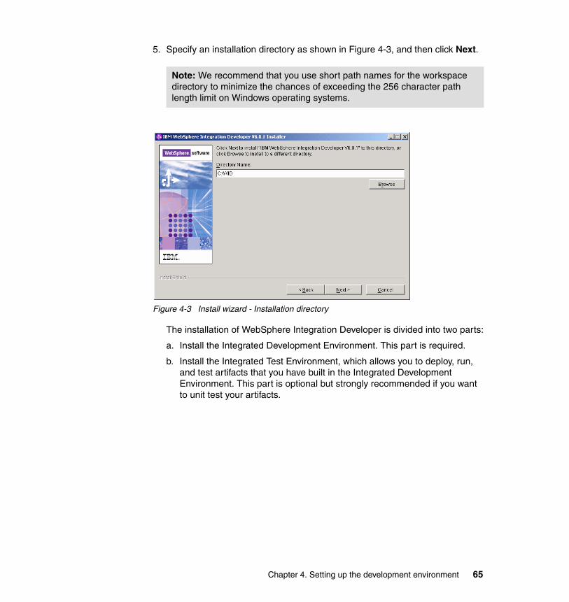
5. Specify an installation directory as shown in Figure 4-3, and then click Next.
Figure 4-3 Install wizard - Installation directory
The installation of WebSphere Integration Developer is divided into two parts:
a. Install the Integrated Development Environment. This part is required.
b. Install the Integrated Test Environment, which allows you to deploy, run, and test artifacts that you have built in the Integrated Development Environment. This part is optional but strongly recommended if you want to unit test your artifacts.
Note: We recommend that you use short path names for the workspace directory to minimize the chances of exceeding the 256 character path length limit on Windows operating systems.
Chapter 4. Setting up the development environment 65

6. Click Integrated Test Environment and click Next (Figure 4-4).
Figure 4-4 Install wizard - Integrated Test Environment
The Integrated Test Environment of WebSphere Integration Developer offers two server types: WebSphere Process Server and WebSphere Enterprise Service Bus. We recommend installing both.
7. Select WebSphere Enterprise Service Bus in addition to WebSphere Process Server and click Next (Figure 4-5).
Figure 4-5 Install wizard - Select Integration Test Environment
66 Getting Started with WebSphere Enterprise Service Bus V6
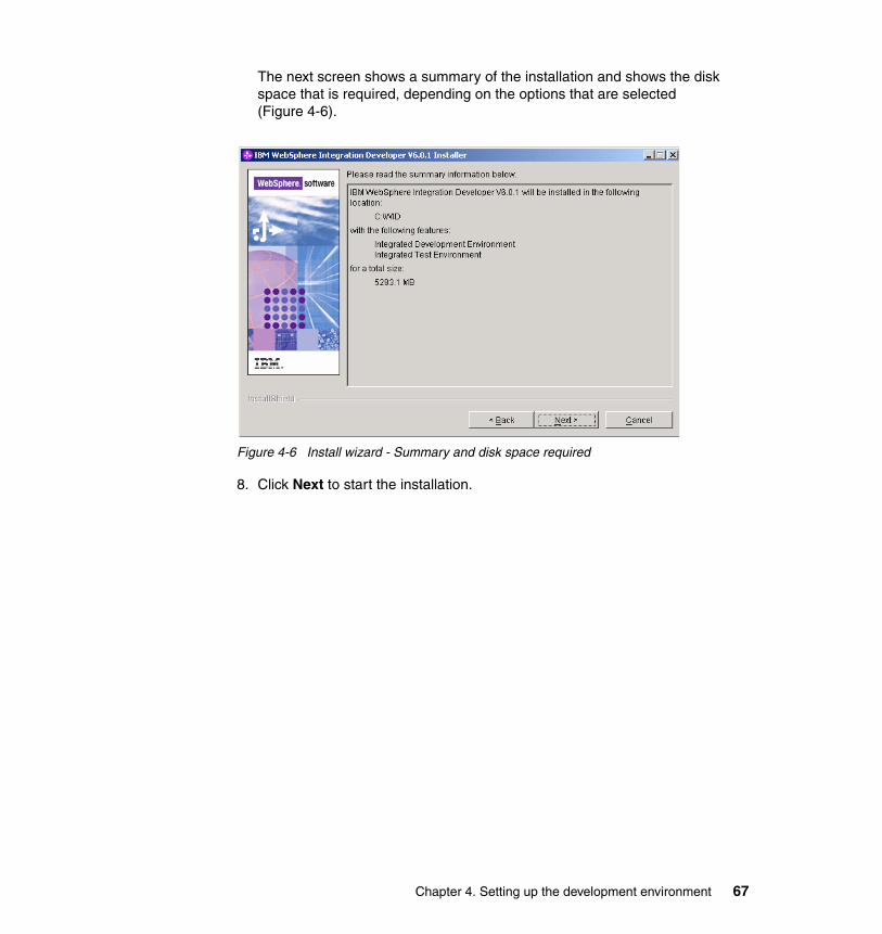
The next screen shows a summary of the installation and shows the disk space that is required, depending on the options that are selected (Figure 4-6).
Figure 4-6 Install wizard - Summary and disk space required
8. Click Next to start the installation.
Chapter 4. Setting up the development environment 67
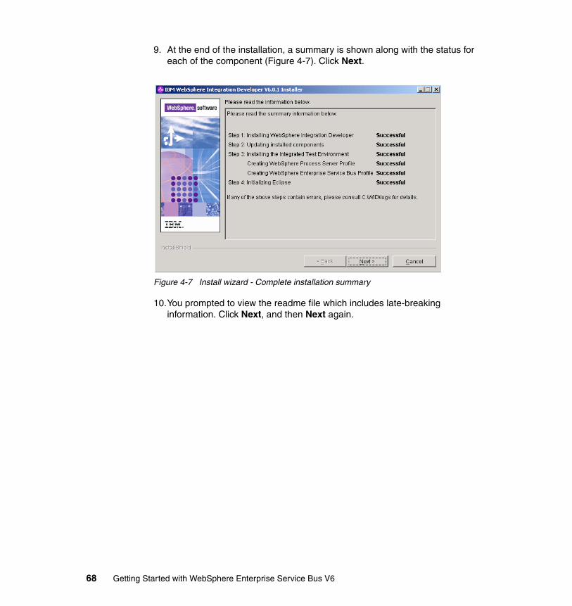
9. At the end of the installation, a summary is shown along with the status for each of the component (Figure 4-7). Click Next.
Figure 4-7 Install wizard - Complete installation summary
10.You prompted to view the readme file which includes late-breaking information. Click Next, and then Next again.
68 Getting Started with WebSphere Enterprise Service Bus V6
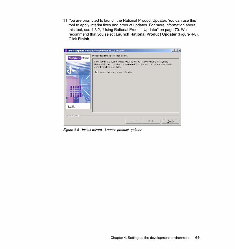
11.You are prompted to launch the Rational Product Updater. You can use this tool to apply interim fixes and product updates. For more information about this tool, see 4.3.2, “Using Rational Product Updater” on page 70. We recommend that you select Launch Rational Product Updater (Figure 4-8). Click Finish.
Figure 4-8 Install wizard - Launch product updater
Chapter 4. Setting up the development environment 69
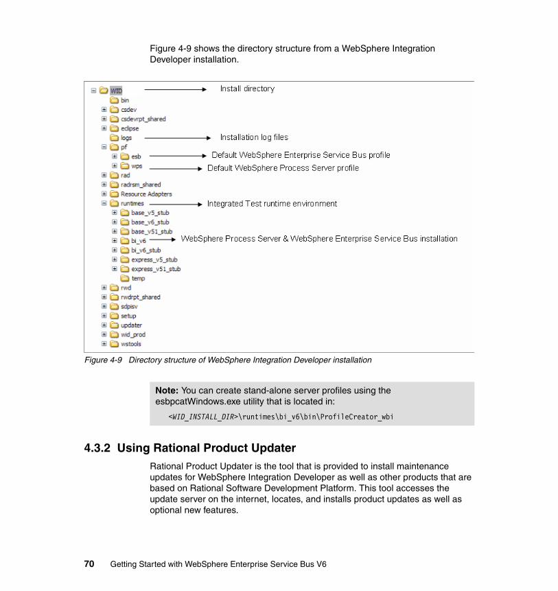
Figure 4-9 shows the directory structure from a WebSphere Integration Developer installation.
Figure 4-9 Directory structure of WebSphere Integration Developer installation
4.3.2 Using Rational Product UpdaterRational Product Updater is the tool that is provided to install maintenance updates for WebSphere Integration Developer as well as other products that are based on Rational Software Development Platform. This tool accesses the update server on the internet, locates, and installs product updates as well as optional new features.
Note: You can create stand-alone server profiles using the esbpcatWindows.exe utility that is located in:
<WID_INSTALL_DIR>\runtimes\bi_v6\bin\ProfileCreator_wbi
70 Getting Started with WebSphere Enterprise Service Bus V6
After completing a successful installation, we strongly recommended that you check for product updates so that you can install fixes and prevent encountering known problems.
You can launch Rational Product Updater from the installation wizard or by selecting Start → Programs → IBM WebSphere → Integration Developer V6.0.1 → Rational Product Updater.
It is possible to change the update site preference within Rational Product Updater, so updates can be installed from a local or a network drive rather than from the internet update server. You need to download the updates to a local driver and change the update site preference.
You can download recommended updates for WebSphere Integration Developer from:
http://www-1.ibm.com/support/docview.wss?rs=2308&uid=swg27006685
You can find further information about changing the update site preference at:
http://publib.boulder.ibm.com/infocenter/dmndhelp/v6rxmx/index.jsp?topic=/com.ibm.orca.updater.doc/topics/tupdatesites.html
While you can modify the update policy as required, you can also use the update policy that is shipped with each fixpack. This can be found in the WID directory after unzipping the fixpack. The filename is policy_601_interim_fixnnn.xml, where nnn is the fix number.
After completing WebSphere Integration Developer installation, we installed updates using Rational Product Updater. We downloaded the updates and used the update policy that shipped with the fix. The following provides details on each step in installing an update using Rational Product Updater:
1. If the Rational Product Updater s not running, launch it by selecting Start → Programs → IBM WebSphere → Integration Developer V6.0.1 → Rational Product Updater.
Chapter 4. Setting up the development environment 71
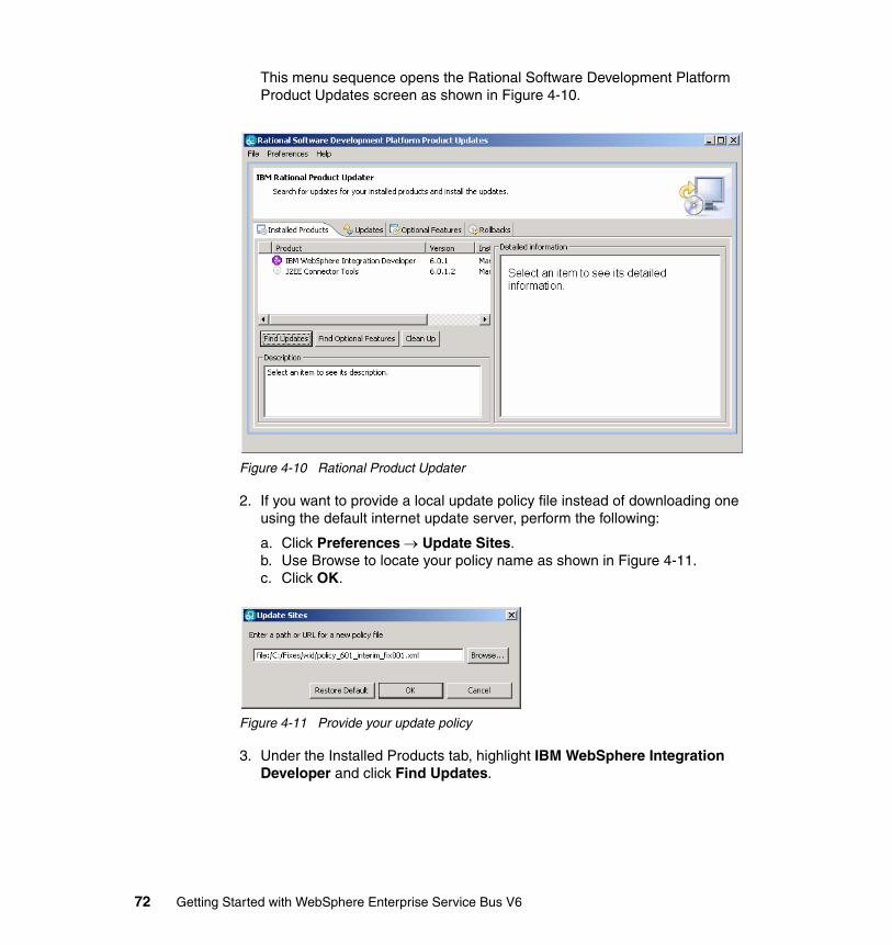
This menu sequence opens the Rational Software Development Platform Product Updates screen as shown in Figure 4-10.
Figure 4-10 Rational Product Updater
2. If you want to provide a local update policy file instead of downloading one using the default internet update server, perform the following:
a. Click Preferences → Update Sites.b. Use Browse to locate your policy name as shown in Figure 4-11.c. Click OK.
Figure 4-11 Provide your update policy
3. Under the Installed Products tab, highlight IBM WebSphere Integration Developer and click Find Updates.
72 Getting Started with WebSphere Enterprise Service Bus V6

4. When you have located the updates (either locally or using the Internet) the Product Updater switches to the Updates view (Figure 4-12).
Figure 4-12 Selecting the updates to install
Highlighting each update that is shown in the update window provides a brief description of that update in the Description box and detailed information about that update in the Detailed information box. You can select or deselect an update to install using the check box.
After completing selections, click Install Updates to start the installation.
Chapter 4. Setting up the development environment 73
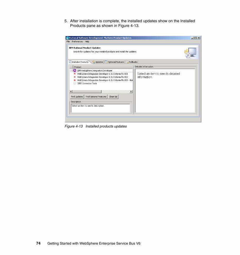
5. After installation is complete, the installed updates show on the Installed Products pane as shown in Figure 4-13.
Figure 4-13 Installed products updates
74 Getting Started with WebSphere Enterprise Service Bus V6

4.3.3 Starting WebSphere Integration DeveloperTo start WebSphere Integration Developer, perform the following:
1. Click Start → Programs → IBM WebSphere → Integration Developer V6.0.1 → WebSphere Integration Developer V6.0.1.
2. This menu sequence launches the Workspace Launcher window (Figure 4-14). Enter a path where a workspace should be created and click OK.
Figure 4-14 Workspace Launcher
Note: We recommend that you use short path names for the workspace directory to minimize the chances of exceeding the 256 character path length limit on Windows operating systems.
Chapter 4. Setting up the development environment 75
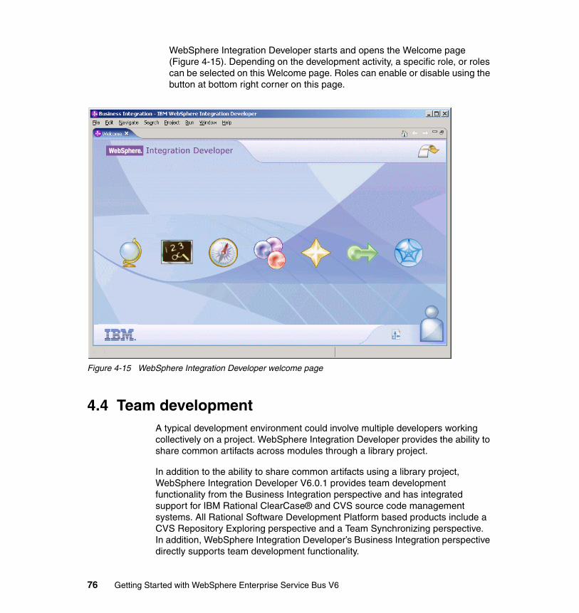
WebSphere Integration Developer starts and opens the Welcome page (Figure 4-15). Depending on the development activity, a specific role, or roles can be selected on this Welcome page. Roles can enable or disable using the button at bottom right corner on this page.
Figure 4-15 WebSphere Integration Developer welcome page
4.4 Team developmentA typical development environment could involve multiple developers working collectively on a project. WebSphere Integration Developer provides the ability to share common artifacts across modules through a library project.
In addition to the ability to share common artifacts using a library project, WebSphere Integration Developer V6.0.1 provides team development functionality from the Business Integration perspective and has integrated support for IBM Rational ClearCase® and CVS source code management systems. All Rational Software Development Platform based products include a CVS Repository Exploring perspective and a Team Synchronizing perspective. In addition, WebSphere Integration Developer’s Business Integration perspective directly supports team development functionality.
76 Getting Started with WebSphere Enterprise Service Bus V6
The Business Integration perspective in WebSphere Integration Developer V6.0.1 supports the following operations for team development support.
� Share a project
� Synchronize changes between the local application and source code repository
� Commit local changes to source code repository
� Update local workspace artifacts with the version on source code repository
You must configure a connection to the CVS server using CVS Repository Exploring perspective. For information about CVS server configuration and implementation and how to connect a CVS client to it, see Rational Application Developer V6 Programming Guide, SG24-6449.
The primary artifact that will be managed in a team development environment is a module. While WebSphere Integration Developer generates several staging projects when each application project is built, these generated projects are marked as derived. By default, CVS does not commit any files or folders from the generated staging projects marked as derived. The staging projects is regenerated when a user extracts the module from CVS, because WebSphere Integration Developer by default has the Build Automatically flag selected.
From more information about packaging in WebSphere Integration Developer, refer to:
http://www-128.ibm.com/developerworks/websphere/library/techarticles/0512_phan2/0512_phan2.html
Developers can share the project by checking it into a CVS repository from Business Integration perspective using the following instructions:
1. Right-click a mediation module and select Team → Share Project.
The next screen requires you to select the repository plug-in that will be used for source code management system.
Note: This section assumes the CVS source code management system as the source code repository.
Note: If the default of Build Automatically is modified, you must build the project by selecting Project → Build Project, after you check out from CVS.
Chapter 4. Setting up the development environment 77
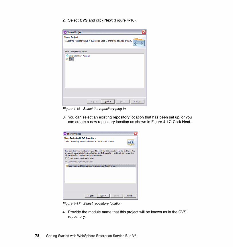
2. Select CVS and click Next (Figure 4-16).
Figure 4-16 Select the repository plug-in
3. You can select an existing repository location that has been set up, or you can create a new repository location as shown in Figure 4-17. Click Next.
Figure 4-17 Select repository location
4. Provide the module name that this project will be known as in the CVS repository.
78 Getting Started with WebSphere Enterprise Service Bus V6
It is important that you select Use project name as module name as shown in Figure 4-18. In WebSphere Integration Developer, the module file depends on the module name, and any changes in the module name results in naming errors.
Figure 4-18 Module name
Chapter 4. Setting up the development environment 79
5. The next panel shows the all the files for the module that are checked into CVS repository (Figure 4-19). Click Finish.
Figure 4-19 Share project resources
6. There are uncommitted changes that are yet to be shared, as shown in Figure 4-20. Click Yes.
Figure 4-20 Commit changes
80 Getting Started with WebSphere Enterprise Service Bus V6
7. You are presented with a window that shows you the number of files that are to be added to CVS repository. Click Details to see the list of files that will be added (Figure 4-21). Because the entire module is being added to CVS repository, all the files are selected. Click Yes.
Figure 4-21 Number of resources
8. You can add an optional comment on version tracking as shown in Figure 4-22. Click OK.
Figure 4-22 Version
All the files and folders for the module are uploaded to the CVS repository, and the module is available for check out. In the workspace, the module and the artifacts within the module that have been shared are marked with a small disk
Chapter 4. Setting up the development environment 81
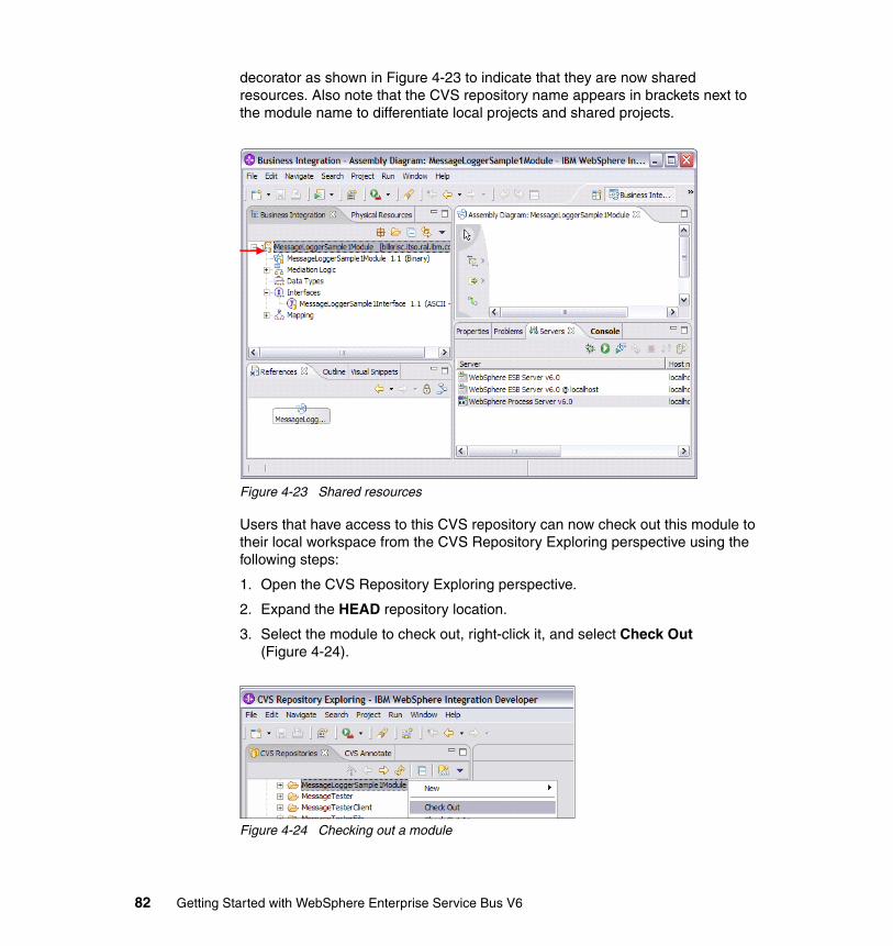
decorator as shown in Figure 4-23 to indicate that they are now shared resources. Also note that the CVS repository name appears in brackets next to the module name to differentiate local projects and shared projects.
Figure 4-23 Shared resources
Users that have access to this CVS repository can now check out this module to their local workspace from the CVS Repository Exploring perspective using the following steps:
1. Open the CVS Repository Exploring perspective.
2. Expand the HEAD repository location.
3. Select the module to check out, right-click it, and select Check Out (Figure 4-24).
Figure 4-24 Checking out a module
82 Getting Started with WebSphere Enterprise Service Bus V6
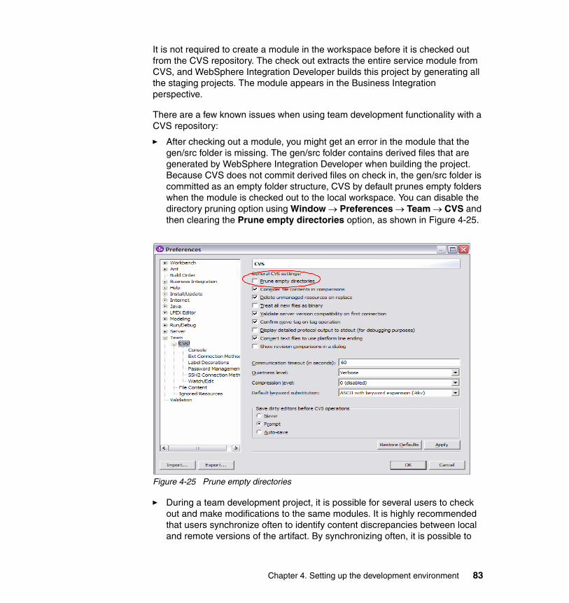
It is not required to create a module in the workspace before it is checked out from the CVS repository. The check out extracts the entire service module from CVS, and WebSphere Integration Developer builds this project by generating all the staging projects. The module appears in the Business Integration perspective.
There are a few known issues when using team development functionality with a CVS repository:
� After checking out a module, you might get an error in the module that the gen/src folder is missing. The gen/src folder contains derived files that are generated by WebSphere Integration Developer when building the project. Because CVS does not commit derived files on check in, the gen/src folder is committed as an empty folder structure, CVS by default prunes empty folders when the module is checked out to the local workspace. You can disable the directory pruning option using Window → Preferences → Team → CVS and then clearing the Prune empty directories option, as shown in Figure 4-25.
Figure 4-25 Prune empty directories
� During a team development project, it is possible for several users to check out and make modifications to the same modules. It is highly recommended that users synchronize often to identify content discrepancies between local and remote versions of the artifact. By synchronizing often, it is possible to
Chapter 4. Setting up the development environment 83
identify conflicts early. It is good practice to avoid having two or more people developing the same artifact at the same time.
Synchronizing between the local workspace and CVS repository can be performed from the Business Integration perspective by right-clicking a project and selecting Team → Synchronize with repository.
� Eclipse provides the option of committing files to CVS repository without synchronizing the workspace first by right-clicking a project and selecting Team → Commit from the context menu. We do not recommended this approach because all the local changes are committed to the server and will overwrite any existing conflicts between the local workspace and the CVS repository. We recommended that you perform a synchronize with the repository first and check any existing conflicts before committing the local workspace to CVS.
� If synchronize with repository shows conflicts between the local workspace and the repository, we recommended that you check the conflicts and, accordingly, either update the local workspace with the remote version on CVS or commit the local workspace version to CVS.
� In addition to service modules, it is possible to manage library projects using a CVS repository. It should be noted that module projects could be dependant on a library and that changes to artifacts in the library can affect these module projects.
4.5 Integration test considerationsThis section refers to the development environment not just as a software tool or a development workstation but as a complete stage in the integration development life cycle. Typically, a development project consists of a number of integration developers building a solution. Each developer is responsible for a set of deliverables and need not be concerned with the specifics of how one module connects to another.
Integration developers write mediation modules, unit test their components using the Integration Test Client, and commit their modules to a source repository, such as CVS. Assembling the complete solution by specifying bindings between modules is the responsibility of the integration specialist.
Note: For more in-depth information about team development, see Team development with WebSphere Integration Developer and WebSphere Process Server: Developing applications using CVS, which is available at:
http://www.ibm.com/developerworks/websphere/library/techarticles/0604_beers/0604_beers.html
84 Getting Started with WebSphere Enterprise Service Bus V6
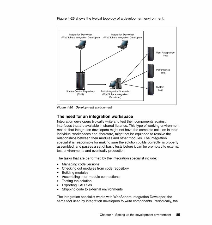
Figure 4-26 shows the typical topology of a development environment.
Figure 4-26 Development environment
The need for an integration workspaceIntegration developers typically write and test their components against interfaces that are available in shared libraries. This type of working environment means that integration developers might not have the complete solution in their individual workspaces and, therefore, might not be equipped to resolve the relationships between their modules and other modules. The integration specialist is responsible for making sure the solution builds correctly, is properly assembled, and passes a set of basic tests before it can be promoted to external test environments and eventually production.
The tasks that are performed by the integration specialist include:
� Managing code versions� Checking out modules from code repository� Building modules� Assembling inter-module connections� Testing the solution� Exporting EAR files� Shipping code to external environments
The integration specialist works with WebSphere Integration Developer, the same tool used by integration developers to write components. Periodically, the
User AcceptanceTest
PerformanceTest
SystemTestBuild/Integration Specialist
(WebSphere IntegrationDeveloper)
Source Control Repository(CVS)
Integration Developer(WebSphere Integration Developer)
Integration Developer(WebSphere Integration Developer)
Chapter 4. Setting up the development environment 85
integration developer enforces a code freeze, checks all modules out from the source code repository, ensures all modules build without errors, makes sure the bindings between modules are set correctly, smoke-tests the solution, tags all modules with a version level, and exports the complete solution as a set of EAR files to be promoted to external test environments.
It is common, at the start of an integration project, to allocate integration test activities to a member of the development team. However, as the project grows and the number of activities increases, you need a dedicated resource to own these tasks and to manage communications between the development environment and other external environments.
Given the nature of integration projects, you should plan for a dedicated resource to fulfill the role of the integration specialist.
4.6 Troubleshooting installation issuesThe final panel of WebSphere Integration Developer installation provides a detailed summary of the installation. This panel shows all the components that were selected for installation and shows the status of the installation for each of these components. This panel also shows the directory name where logs are located.
The logs are located in the WID_INSTALL_DIR\logs directory. If any of the components show a status of failure, you should review the logs for further information.
Depending on the components selected for installation, an installation of WebSphere Integration Developer can also install a complete WebSphere Process Server V6.0.1 and WebSphere Enterprise Service Bus V6.0.1 environment to be used as integration test servers.
The servers are installed in the WID_INSTALL_DIR\runtimes\bi_v6 directory. The logs for the server installation are in the WID_INSTALL_DIR\runtimes\bi_v6\logs directory.
86 Getting Started with WebSphere Enterprise Service Bus V6
If the installation summary shows a failure when installing the server, you need to check the logs for the server. In addition to logs, you can enable further debugging for installation by starting the installation using the following command:
<disk1>\setup\setup.exe -log # !C:\install-log.txt @ALL
For silent installation using a response file, you can start further debugging using the following command:
<..disk1\setup>\setup.exe -silent -options c:\myresponsefile.txt -log # !C:\install-log.txt @ALL
Finally, we also recommended that you check the WebSphere Integration Developer support Web site for any known issues:
http://www-306.ibm.com/software/integration/wid/support/
Chapter 4. Setting up the development environment 87

88 Getting Started with WebSphere Enterprise Service Bus V6
Chapter 5. Setting up the runtime environment
This chapter discusses the WebSphere Enterprise Service Bus runtime environment. We provide an overview of the runtime environment and a description of the runtime topologies that can be configured. We also provide details of the runtime environments that we installed. Finally, we discuss some considerations for establishing various test and production environments that address common requirements.
This chapter includes the following topics:
� Overview of the runtime environment� Stand-alone server topology� Network Deployment topology� Extending WebSphere Application Server V6� Installing WebSphere Enterprise Service Bus� Guidelines for staged test and production environments� Problem determination for runtime installation and customization
5
© Copyright IBM Corp. 2006. All rights reserved. 89
5.1 Overview of the runtime environmentIn this section, we discuss the runtime environment in general terms, so that you can get an understanding of what is involved in establishing the runtime environments needed for development, test, and production activities. If you are familiar with WebSphere Application Server V5, the terminology and configuration topologies are identical to those that you have already encountered. If you have experience with WebSphere Application Server V6, you are already acquainted with the idea of a profile. It is used in the same way for WebSphere Enterprise Service Bus.
5.1.1 Hardware and software requirementsIt is always best to consult the WebSphere Enterprise Service Bus product Web site to obtain the most up-to-date information regarding supported hardware and software. You can find this information at:
http://www.ibm.com/software/integration/wsesb/sysreqs
5.1.2 Consider your current environmentWebSphere Enterprise Service Bus V6.01 is based on WebSphere Application Server Network Deployment V6.0.2.3. Your first decision when planning the runtime environment, is between extending your current WebSphere Application Server Network Deployment environment by adding WebSphere Enterprise Service Bus to it or by creating separate WebSphere Enterprise Service Bus servers.
If you have WebSphere Application Server Network Deployment V6 installed and configured to support your development, test and production requirements, you will most likely want to extend these environments by adding WebSphere Enterprise Service Bus to them. We discuss more about how to do that in 5.4, “Extending WebSphere Application Server V6” on page 101.
If you do not have an existing WebSphere Application Server Network Deployment V6 runtime environment, then you need to create new servers to run WebSphere Enterprise Service Bus. We took this approach, and we discuss the installation and customization steps that we took in detail in 5.5, “Installing WebSphere Enterprise Service Bus” on page 104.
The following sections describe installation and customization steps you take when you do not have an existing WebSphere Application Server Network Deployment V6 installation or, if you do, in the case where you chose to not extend that installation with the WebSphere Enterprise Service Bus libraries.
90 Getting Started with WebSphere Enterprise Service Bus V6
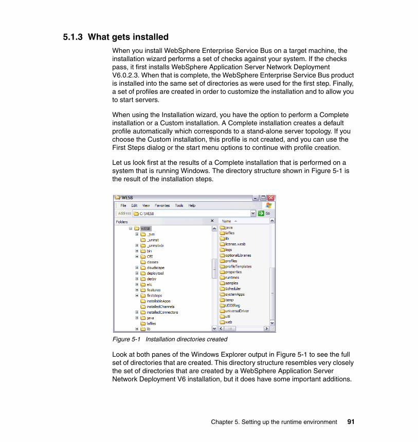
5.1.3 What gets installedWhen you install WebSphere Enterprise Service Bus on a target machine, the installation wizard performs a set of checks against your system. If the checks pass, it first installs WebSphere Application Server Network Deployment V6.0.2.3. When that is complete, the WebSphere Enterprise Service Bus product is installed into the same set of directories as were used for the first step. Finally, a set of profiles are created in order to customize the installation and to allow you to start servers.
When using the Installation wizard, you have the option to perform a Complete installation or a Custom installation. A Complete installation creates a default profile automatically which corresponds to a stand-alone server topology. If you choose the Custom installation, this profile is not created, and you can use the First Steps dialog or the start menu options to continue with profile creation.
Let us look first at the results of a Complete installation that is performed on a system that is running Windows. The directory structure shown in Figure 5-1 is the result of the installation steps.
Figure 5-1 Installation directories created
Look at both panes of the Windows Explorer output in Figure 5-1 to see the full set of directories that are created. This directory structure resembles very closely the set of directories that are created by a WebSphere Application Server Network Deployment V6 installation, but it does have some important additions.
Chapter 5. Setting up the runtime environment 91
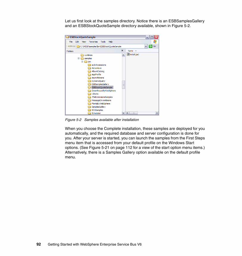
Let us first look at the samples directory. Notice there is an ESBSamplesGallery and an ESBStockQuoteSample directory available, shown in Figure 5-2.
Figure 5-2 Samples available after installation
When you choose the Complete installation, these samples are deployed for you automatically, and the required database and server configuration is done for you. After your server is started, you can launch the samples from the First Steps menu item that is accessed from your default profile on the Windows Start options. (See Figure 5-21 on page 112 for a view of the start option menu items.) Alternatively, there is a Samples Gallery option available on the default profile menu.
92 Getting Started with WebSphere Enterprise Service Bus V6
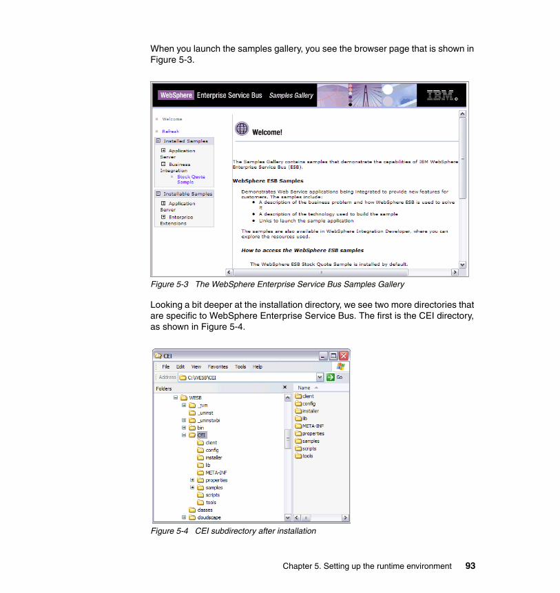
When you launch the samples gallery, you see the browser page that is shown in Figure 5-3.
Figure 5-3 The WebSphere Enterprise Service Bus Samples Gallery
Looking a bit deeper at the installation directory, we see two more directories that are specific to WebSphere Enterprise Service Bus. The first is the CEI directory, as shown in Figure 5-4.
Figure 5-4 CEI subdirectory after installation
Chapter 5. Setting up the runtime environment 93
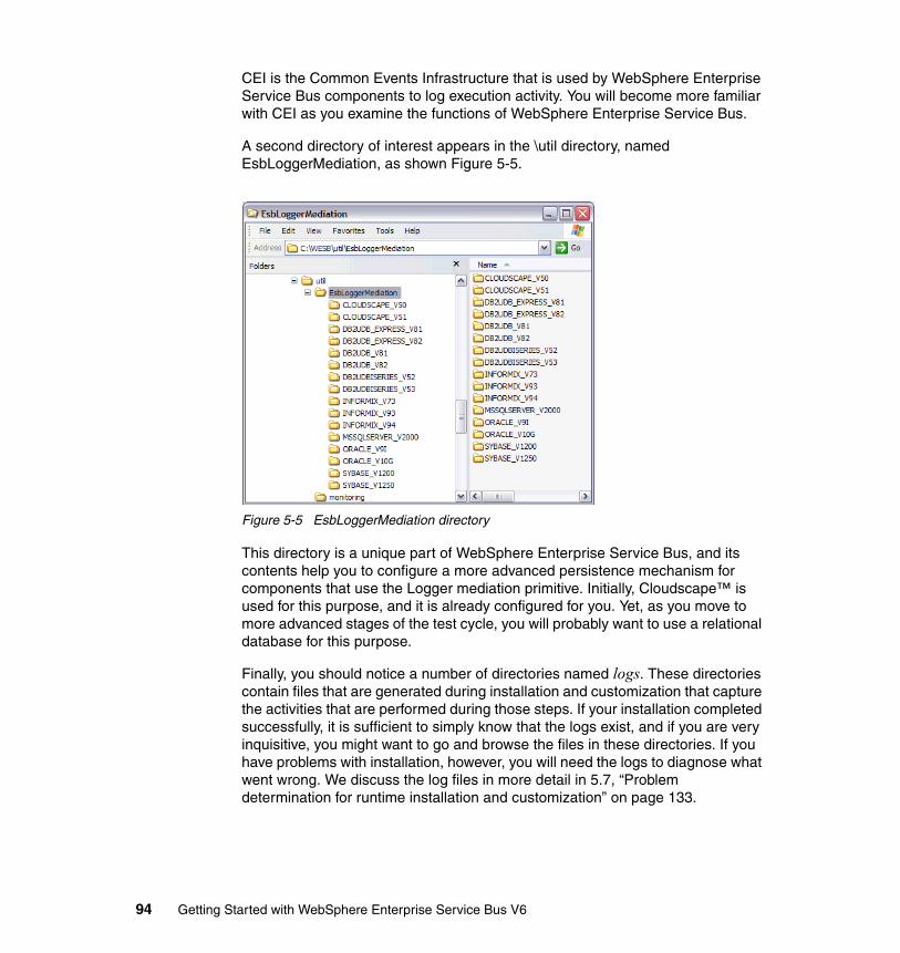
CEI is the Common Events Infrastructure that is used by WebSphere Enterprise Service Bus components to log execution activity. You will become more familiar with CEI as you examine the functions of WebSphere Enterprise Service Bus.
A second directory of interest appears in the \util directory, named EsbLoggerMediation, as shown Figure 5-5.
Figure 5-5 EsbLoggerMediation directory
This directory is a unique part of WebSphere Enterprise Service Bus, and its contents help you to configure a more advanced persistence mechanism for components that use the Logger mediation primitive. Initially, Cloudscape™ is used for this purpose, and it is already configured for you. Yet, as you move to more advanced stages of the test cycle, you will probably want to use a relational database for this purpose.
Finally, you should notice a number of directories named logs. These directories contain files that are generated during installation and customization that capture the activities that are performed during those steps. If your installation completed successfully, it is sufficient to simply know that the logs exist, and if you are very inquisitive, you might want to go and browse the files in these directories. If you have problems with installation, however, you will need the logs to diagnose what went wrong. We discuss the log files in more detail in 5.7, “Problem determination for runtime installation and customization” on page 133.
94 Getting Started with WebSphere Enterprise Service Bus V6
5.1.4 What gets customizedGenerally, the process of customization is one that modifies the product installation libraries so that a working version is created. For WebSphere Enterprise Service Bus, the customization process is encapsulated by the tasks performed to create profiles. A profile is a set of directories and files on the machine that are specific to a given server. You can have multiple profiles on a machine, each representing a different server, its configuration, and the commands to interact with it. These profiles make use of the product installation libraries as though they were in read-only mode. Files that must be updated for a particular server are copied and kept as part of the profile.
If you choose a Complete installation, a default profile is created for you, which provides a customized stand-alone server. You can continue to create other profiles for a Deployment Manager and a Custom Node, which we discuss in detail in 5.5.2, “A common development integration test runtime environment” on page 113. If you choose to perform a Custom installation, no profiles are created automatically, and you have full control over that process using the First Steps dialog.
All of the profiles can coexist on a given machine, although depending on what kind they are and how they were built (using common or unique TCP/IP ports, for example), the servers that are associated with them cannot be started at the same time.
Chapter 5. Setting up the runtime environment 95
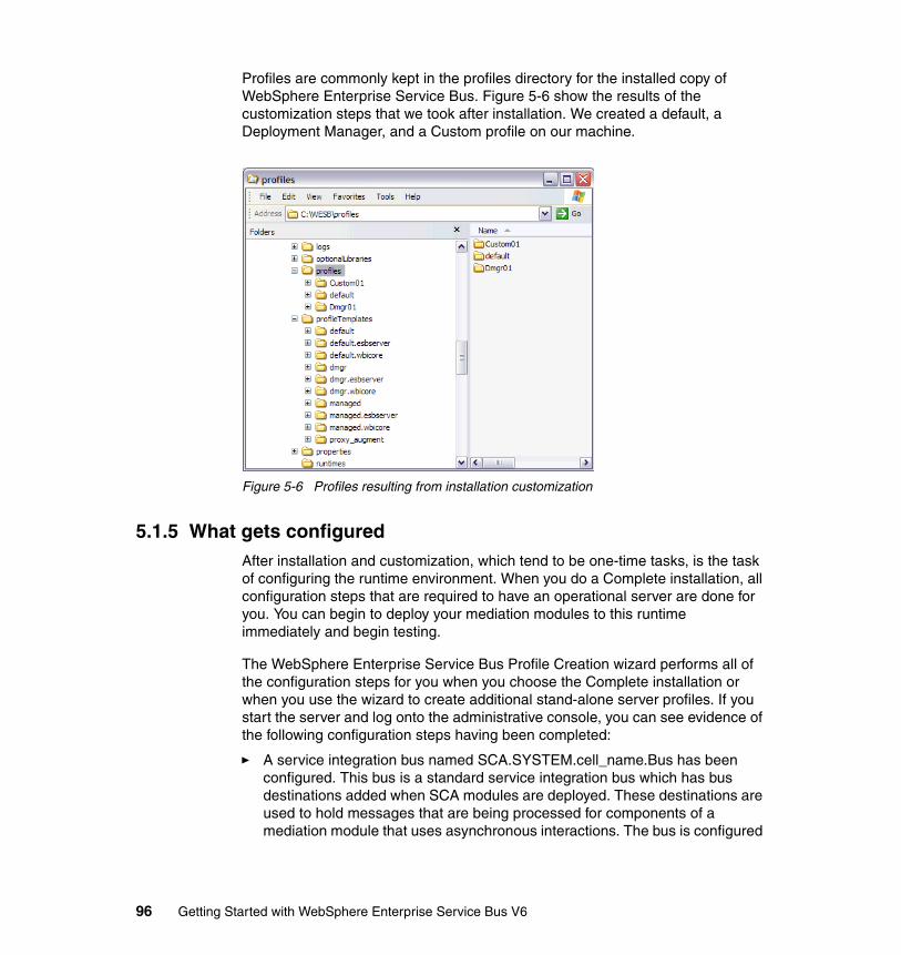
Profiles are commonly kept in the profiles directory for the installed copy of WebSphere Enterprise Service Bus. Figure 5-6 show the results of the customization steps that we took after installation. We created a default, a Deployment Manager, and a Custom profile on our machine.
Figure 5-6 Profiles resulting from installation customization
5.1.5 What gets configuredAfter installation and customization, which tend to be one-time tasks, is the task of configuring the runtime environment. When you do a Complete installation, all configuration steps that are required to have an operational server are done for you. You can begin to deploy your mediation modules to this runtime immediately and begin testing.
The WebSphere Enterprise Service Bus Profile Creation wizard performs all of the configuration steps for you when you choose the Complete installation or when you use the wizard to create additional stand-alone server profiles. If you start the server and log onto the administrative console, you can see evidence of the following configuration steps having been completed:
� A service integration bus named SCA.SYSTEM.cell_name.Bus has been configured. This bus is a standard service integration bus which has bus destinations added when SCA modules are deployed. These destinations are used to hold messages that are being processed for components of a mediation module that uses asynchronous interactions. The bus is configured
96 Getting Started with WebSphere Enterprise Service Bus V6
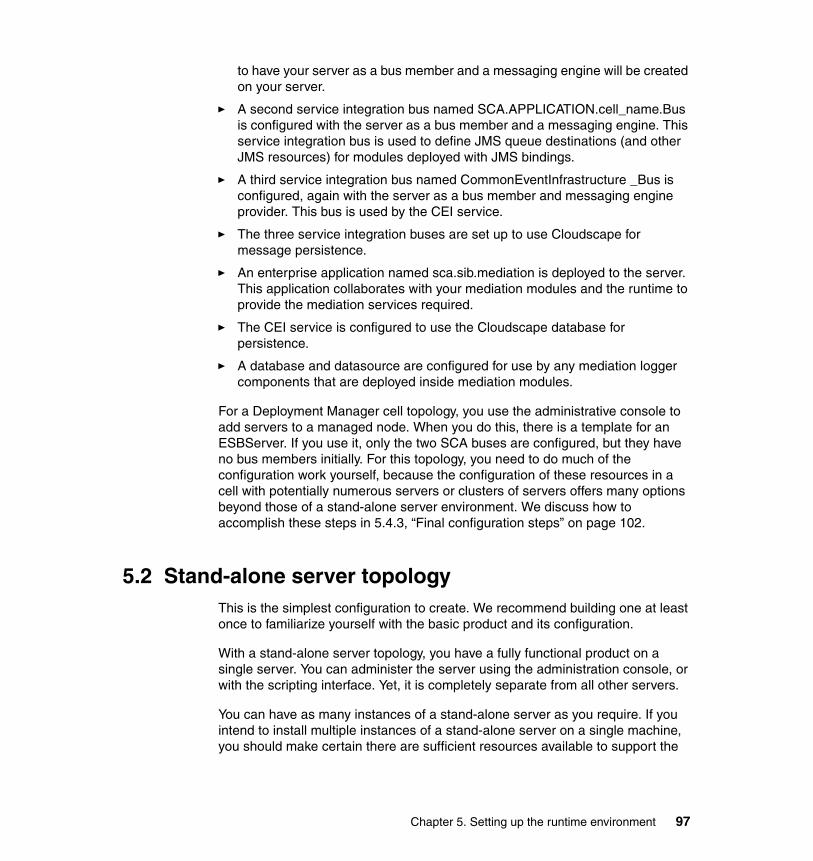
to have your server as a bus member and a messaging engine will be created on your server.
� A second service integration bus named SCA.APPLICATION.cell_name.Bus is configured with the server as a bus member and a messaging engine. This service integration bus is used to define JMS queue destinations (and other JMS resources) for modules deployed with JMS bindings.
� A third service integration bus named CommonEventInfrastructure _Bus is configured, again with the server as a bus member and messaging engine provider. This bus is used by the CEI service.
� The three service integration buses are set up to use Cloudscape for message persistence.
� An enterprise application named sca.sib.mediation is deployed to the server. This application collaborates with your mediation modules and the runtime to provide the mediation services required.
� The CEI service is configured to use the Cloudscape database for persistence.
� A database and datasource are configured for use by any mediation logger components that are deployed inside mediation modules.
For a Deployment Manager cell topology, you use the administrative console to add servers to a managed node. When you do this, there is a template for an ESBServer. If you use it, only the two SCA buses are configured, but they have no bus members initially. For this topology, you need to do much of the configuration work yourself, because the configuration of these resources in a cell with potentially numerous servers or clusters of servers offers many options beyond those of a stand-alone server environment. We discuss how to accomplish these steps in 5.4.3, “Final configuration steps” on page 102.
5.2 Stand-alone server topologyThis is the simplest configuration to create. We recommend building one at least once to familiarize yourself with the basic product and its configuration.
With a stand-alone server topology, you have a fully functional product on a single server. You can administer the server using the administration console, or with the scripting interface. Yet, it is completely separate from all other servers.
You can have as many instances of a stand-alone server as you require. If you intend to install multiple instances of a stand-alone server on a single machine, you should make certain there are sufficient resources available to support the
Chapter 5. Setting up the runtime environment 97
workload. You should also take care to use unique TCP/IP ports for each stand-alone server if you intend to run them concurrently.
When you install WebSphere Enterprise Service Bus, you are copying the product libraries to the target machine, and they are not modified afterward, except through the installation of maintenance to the product. Installation only needs to happen once for any machine that will run WebSphere Enterprise Service Bus in any topology.
In order to create a customized runtime server, you create a profile. If you intend to customize multiple servers on a single machine, the names of the profiles must be unique. Figure 5-7 illustrates a stand-alone server with the default profile.
Figure 5-7 Stand-alone server topology
There are occasions when you might want to install WebSphere Enterprise Service Bus more than once on a given machine. Consider a situation where you want to create a system integration test (SIT) environment, and a quality assurance (QA) environment on the same machine. You could install the product twice, and create two profiles to support the two test environments. You would also have the flexibility to install maintenance for WebSphere Enterprise Service Bus into the SIT environment without disturbing the QA environment. When fully tested, the service could subsequently be installed to the QA environment.
Tip: Installing WebSphere Enterprise Service Bus a second time on the same machine gives you the ability to run servers at different maintenance levels.
Machine A
WebSphere Application Server
WebSphere Enterprise Service Bus
Core product files(System files)
Profile, default
Serverserver1
98 Getting Started with WebSphere Enterprise Service Bus V6
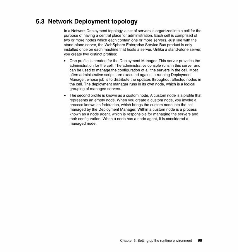
5.3 Network Deployment topologyIn a Network Deployment topology, a set of servers is organized into a cell for the purpose of having a central place for administration. Each cell is comprised of two or more nodes which each contain one or more servers. Just like with the stand-alone server, the WebSphere Enterprise Service Bus product is only installed once on each machine that hosts a server. Unlike a stand-alone server, you create two distinct profiles:
� One profile is created for the Deployment Manager. This server provides the administration for the cell. The administrative console runs in this server and can be used to manage the configuration of all the servers in the cell. Most often administrative scripts are executed against a running Deployment Manager, whose job is to distribute the updates throughout affected nodes in the cell. The deployment manager runs in its own node, which is a logical grouping of managed servers.
� The second profile is known as a custom node. A custom node is a profile that represents an empty node. When you create a custom node, you invoke a process known as federation, which brings the custom node into the cell managed by the Deployment Manager. Within a custom node is a process known as a node agent, which is responsible for managing the servers and their configuration. When a node has a node agent, it is considered a managed node.
Chapter 5. Setting up the runtime environment 99
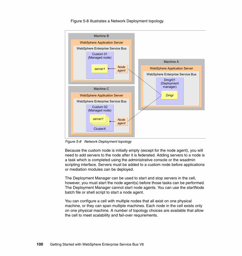
Figure 5-8 illustrates a Network Deployment topology.
Figure 5-8 Network Deployment topology
Because the custom node is initially empty (except for the node agent), you will need to add servers to the node after it is federated. Adding servers to a node is a task which is completed using the administrative console or the wsadmin scripting interface. Servers must be added to a custom node before applications or mediation modules can be deployed.
The Deployment Manager can be used to start and stop servers in the cell, however, you must start the node agent(s) before those tasks can be performed. The Deployment Manager cannot start node agents. You can use the startNode batch file or shell script to start a node agent.
You can configure a cell with multiple nodes that all exist on one physical machine, or they can span multiple machines. Each node in the cell exists only on one physical machine. A number of topology choices are available that allow the cell to meet scalability and fail-over requirements.
Machine C
WebSphere Application Server
WebSphere Enterprise Service Bus
Custom 02(Managed node)
server1server1server1
ClusterX
Nodeagent
Machine B
WebSphere Application Server
WebSphere Enterprise Service Bus
Custom 01(Managed node)
server1 Nodeagent
Machine A
WebSphere Application Server
WebSphere Enterprise Service Bus
Dmgr01(Deployment
manager)
Dmgr
100 Getting Started with WebSphere Enterprise Service Bus V6
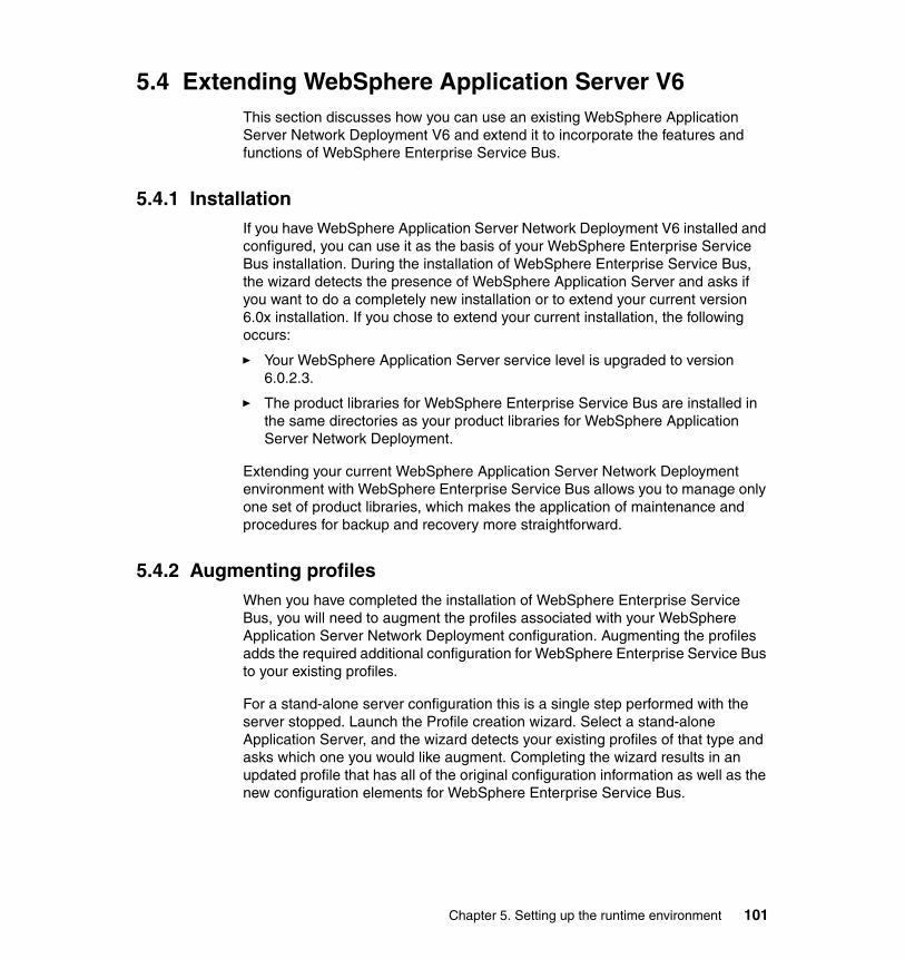
5.4 Extending WebSphere Application Server V6This section discusses how you can use an existing WebSphere Application Server Network Deployment V6 and extend it to incorporate the features and functions of WebSphere Enterprise Service Bus.
5.4.1 Installation If you have WebSphere Application Server Network Deployment V6 installed and configured, you can use it as the basis of your WebSphere Enterprise Service Bus installation. During the installation of WebSphere Enterprise Service Bus, the wizard detects the presence of WebSphere Application Server and asks if you want to do a completely new installation or to extend your current version 6.0x installation. If you chose to extend your current installation, the following occurs:
� Your WebSphere Application Server service level is upgraded to version 6.0.2.3.
� The product libraries for WebSphere Enterprise Service Bus are installed in the same directories as your product libraries for WebSphere Application Server Network Deployment.
Extending your current WebSphere Application Server Network Deployment environment with WebSphere Enterprise Service Bus allows you to manage only one set of product libraries, which makes the application of maintenance and procedures for backup and recovery more straightforward.
5.4.2 Augmenting profilesWhen you have completed the installation of WebSphere Enterprise Service Bus, you will need to augment the profiles associated with your WebSphere Application Server Network Deployment configuration. Augmenting the profiles adds the required additional configuration for WebSphere Enterprise Service Bus to your existing profiles.
For a stand-alone server configuration this is a single step performed with the server stopped. Launch the Profile creation wizard. Select a stand-alone Application Server, and the wizard detects your existing profiles of that type and asks which one you would like augment. Completing the wizard results in an updated profile that has all of the original configuration information as well as the new configuration elements for WebSphere Enterprise Service Bus.
Chapter 5. Setting up the runtime environment 101

If you have a Deployment Manager cell, the process requires several more steps:
1. Stop all of the servers and node agents in the cell.
2. Stop the Deployment Manager.
3. Launch the Profile creation wizard and augment the Deployment Manager profile.
4. Start the Deployment Manager.
5. Unfederate each managed node in the cell. You can use the removeNode command found in the \bin directory of the custom profile for the node.
6. Launch the Profile creation wizard and augment the custom profile that is associated with the unfederated node.
7. Federate the node back into the cell. You can use the addNode command in the \bin directory of the custom profile for the node.
5.4.3 Final configuration stepsAfter you augment the profiles, there remain two final configuration steps.
First, you must enable the server to host SCA modules. If you look at the server before you start this process, you notice that it has the two SCA buses defined to it but has not associated these SCA buses with a messaging engine (there are no bus members). You need to configure the persistence mechanism that is used by the buses and to configure their bus members.
Fortunately, there is a helper dialog to help with this task the first time the server gains ESB capabilities. Follow these steps:
1. In the administrative console, select Servers → Application servers → your_server and the Advanced Configuration link under the Business Integration heading.
2. In the Service Component Architecture section of the pane, select Default Destination Location if you want to be able to deploy mediation modules to this server and if you want to use the messaging resources of this server. Also select the check box that indicates that you want to use the default datasource values for message persistence, which is Cloudscape. By
Note: Use caution when unfederating and federating managed nodes. Options on the command allow you to preserve existing servers and application deployments, but they might be lost if not specified properly. For information about the addNode and removeNode commands, see:
http://publib.boulder.ibm.com/infocenter/dmndhelp/v6rxmx/index.jsp
102 Getting Started with WebSphere Enterprise Service Bus V6
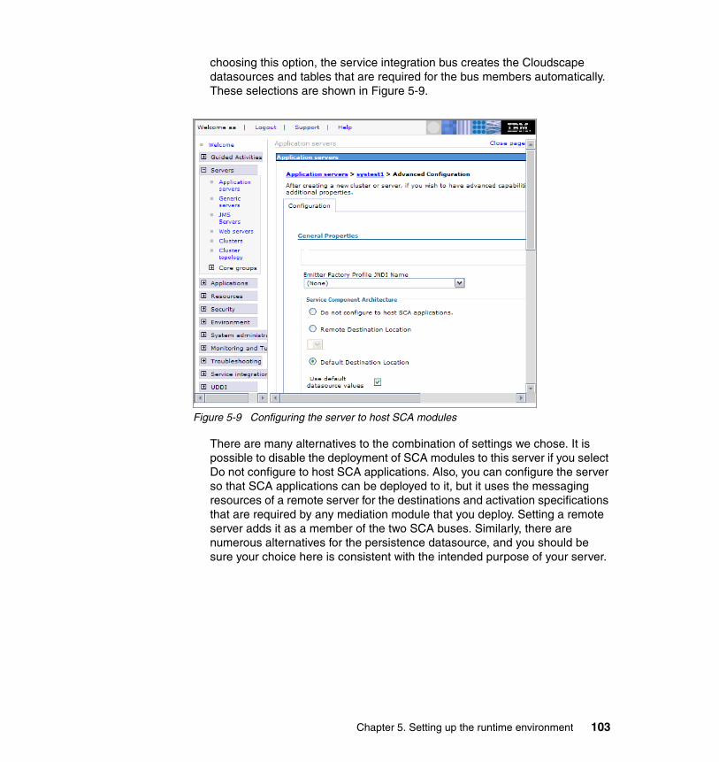
choosing this option, the service integration bus creates the Cloudscape datasources and tables that are required for the bus members automatically. These selections are shown in Figure 5-9.
Figure 5-9 Configuring the server to host SCA modules
There are many alternatives to the combination of settings we chose. It is possible to disable the deployment of SCA modules to this server if you select Do not configure to host SCA applications. Also, you can configure the server so that SCA applications can be deployed to it, but it uses the messaging resources of a remote server for the destinations and activation specifications that are required by any mediation module that you deploy. Setting a remote server adds it as a member of the two SCA buses. Similarly, there are numerous alternatives for the persistence datasource, and you should be sure your choice here is consistent with the intended purpose of your server.
Chapter 5. Setting up the runtime environment 103
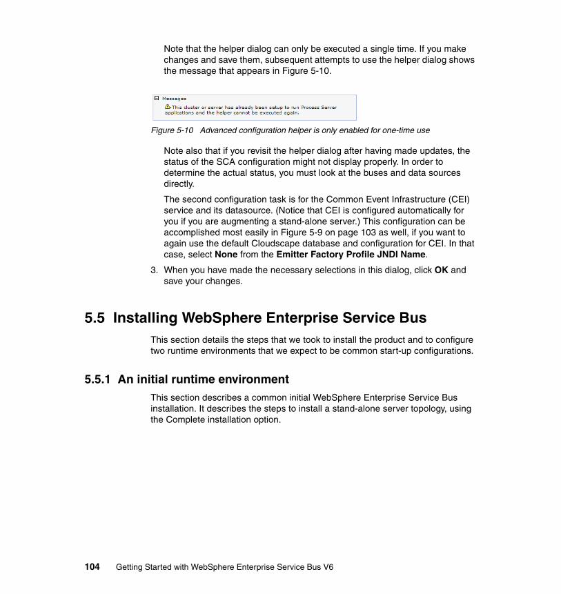
Note that the helper dialog can only be executed a single time. If you make changes and save them, subsequent attempts to use the helper dialog shows the message that appears in Figure 5-10.
Figure 5-10 Advanced configuration helper is only enabled for one-time use
Note also that if you revisit the helper dialog after having made updates, the status of the SCA configuration might not display properly. In order to determine the actual status, you must look at the buses and data sources directly.
The second configuration task is for the Common Event Infrastructure (CEI) service and its datasource. (Notice that CEI is configured automatically for you if you are augmenting a stand-alone server.) This configuration can be accomplished most easily in Figure 5-9 on page 103 as well, if you want to again use the default Cloudscape database and configuration for CEI. In that case, select None from the Emitter Factory Profile JNDI Name.
3. When you have made the necessary selections in this dialog, click OK and save your changes.
5.5 Installing WebSphere Enterprise Service BusThis section details the steps that we took to install the product and to configure two runtime environments that we expect to be common start-up configurations.
5.5.1 An initial runtime environmentThis section describes a common initial WebSphere Enterprise Service Bus installation. It describes the steps to install a stand-alone server topology, using the Complete installation option.
104 Getting Started with WebSphere Enterprise Service Bus V6
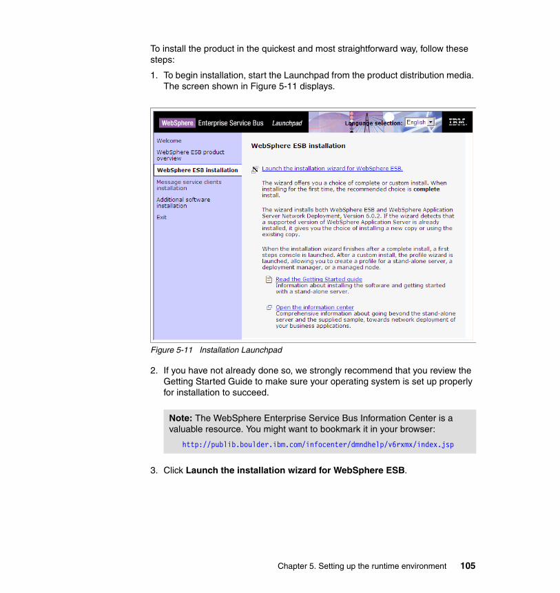
To install the product in the quickest and most straightforward way, follow these steps:
1. To begin installation, start the Launchpad from the product distribution media. The screen shown in Figure 5-11 displays.
Figure 5-11 Installation Launchpad
2. If you have not already done so, we strongly recommend that you review the Getting Started Guide to make sure your operating system is set up properly for installation to succeed.
3. Click Launch the installation wizard for WebSphere ESB.
Note: The WebSphere Enterprise Service Bus Information Center is a valuable resource. You might want to bookmark it in your browser:
http://publib.boulder.ibm.com/infocenter/dmndhelp/v6rxmx/index.jsp
Chapter 5. Setting up the runtime environment 105
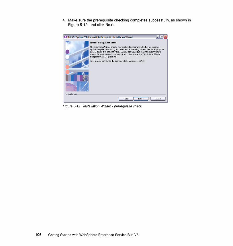
4. Make sure the prerequisite checking completes successfully, as shown in Figure 5-12, and click Next.
Figure 5-12 Installation Wizard - prerequisite check
106 Getting Started with WebSphere Enterprise Service Bus V6

5. Review the results of the prerequisite check for an existing WebSphere Enterprise Service Bus, as shown in Figure 5-13, and click Next.
Figure 5-13 Installation Wizard - checking for existing installation
Note: This installation was on a workstation that had WebSphere Integration Developer installed. So, the checks for existing products found the runtime installed. Because we will not run the WebSphere Integration Developer Test Environment concurrently with the WebSphere Enterprise Service Bus server, we chose not to modify the default port assignments.
Chapter 5. Setting up the runtime environment 107
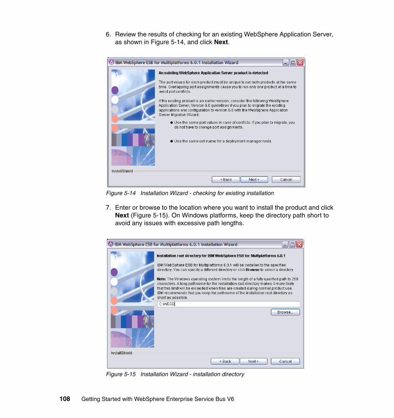
6. Review the results of checking for an existing WebSphere Application Server, as shown in Figure 5-14, and click Next.
Figure 5-14 Installation Wizard - checking for existing installation
7. Enter or browse to the location where you want to install the product and click Next (Figure 5-15). On Windows platforms, keep the directory path short to avoid any issues with excessive path lengths.
Figure 5-15 Installation Wizard - installation directory
108 Getting Started with WebSphere Enterprise Service Bus V6
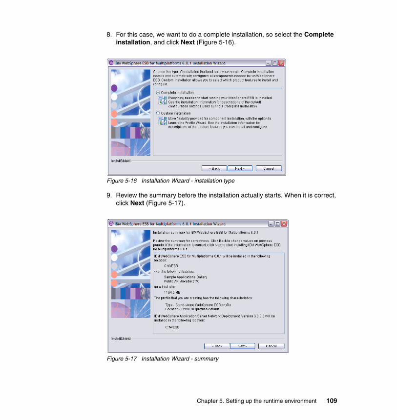
8. For this case, we want to do a complete installation, so select the Complete installation, and click Next (Figure 5-16).
Figure 5-16 Installation Wizard - installation type
9. Review the summary before the installation actually starts. When it is correct, click Next (Figure 5-17).
Figure 5-17 Installation Wizard - summary
Chapter 5. Setting up the runtime environment 109
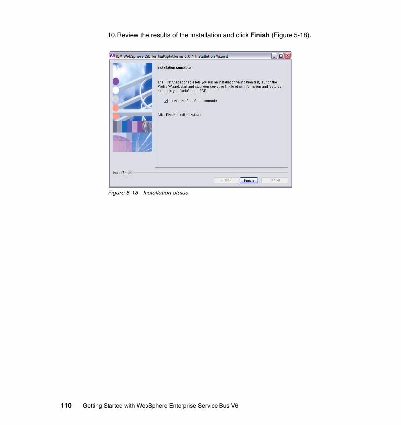
10.Review the results of the installation and click Finish (Figure 5-18).
Figure 5-18 Installation status
110 Getting Started with WebSphere Enterprise Service Bus V6
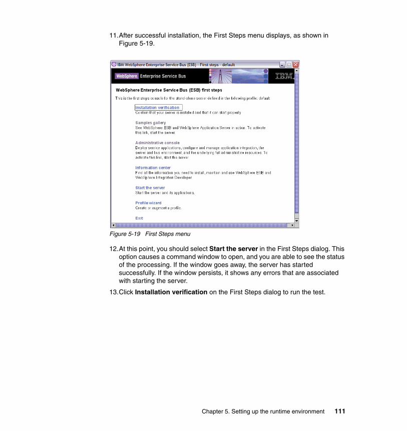
11.After successful installation, the First Steps menu displays, as shown in Figure 5-19.
Figure 5-19 First Steps menu
12.At this point, you should select Start the server in the First Steps dialog. This option causes a command window to open, and you are able to see the status of the processing. If the window goes away, the server has started successfully. If the window persists, it shows any errors that are associated with starting the server.
13.Click Installation verification on the First Steps dialog to run the test.
Chapter 5. Setting up the runtime environment 111
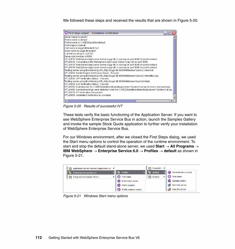
We followed these steps and received the results that are shown in Figure 5-20.
Figure 5-20 Results of successful IVT
These tests verify the basic functioning of the Application Server. If you want to see WebSphere Enterprise Service Bus in action, launch the Samples Gallery and invoke the sample Stock Quote application to further verify your installation of WebSphere Enterprise Service Bus.
For our Windows environment, after we closed the First Steps dialog, we used the Start menu options to control the operation of the runtime environment. To start and stop the default stand-alone server, we used Start → All Programs → IBM WebSphere → Enterprise Service 6.0 → Profiles → default as shown in Figure 5-21.
Figure 5-21 Windows Start menu options
112 Getting Started with WebSphere Enterprise Service Bus V6
5.5.2 A common development integration test runtime environmentIn this section, we describe a runtime environment that uses the Network Deployment topology. This configuration could support multiple developers doing integration test activities. Because we configure a cell with multiple servers, common application packaging and deployment scenarios can be used. For example, it is good practice to deploy Web service providers in a server separate from Web service consumers, and this configuration would support that, while still providing a single point of administrative control.
To configure our cell on a single machine, we only have customization and configuration tasks to complete, which are as follows:
1. Creating a new WebSphere Enterprise Service Bus deployment manager profile.
2. Starting the deployment manager server.
3. Creating a new WebSphere Enterprise Service Bus custom profile.
4. Federating the custom node to the deployment manager.
5. Adding a server to the new managed node.
6. Configuring the SCA service integration buses in the new server.
7. Configuring the CEI service in the new server.
Chapter 5. Setting up the runtime environment 113
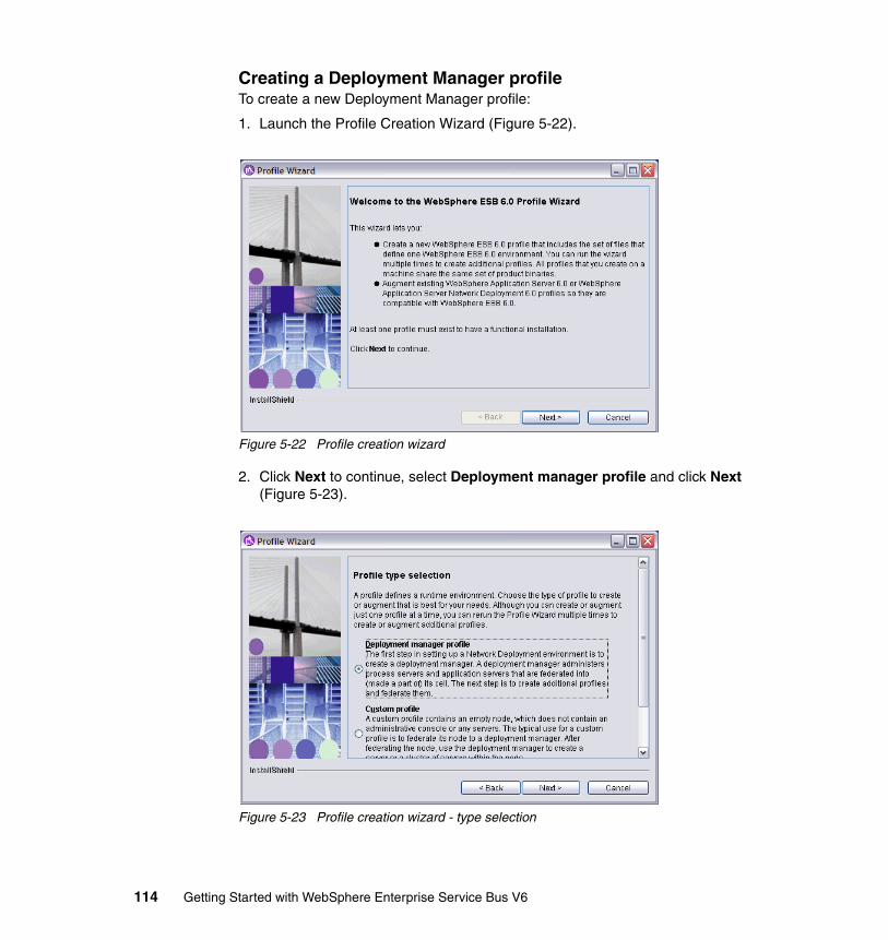
Creating a Deployment Manager profileTo create a new Deployment Manager profile:
1. Launch the Profile Creation Wizard (Figure 5-22).
Figure 5-22 Profile creation wizard
2. Click Next to continue, select Deployment manager profile and click Next (Figure 5-23).
Figure 5-23 Profile creation wizard - type selection
114 Getting Started with WebSphere Enterprise Service Bus V6
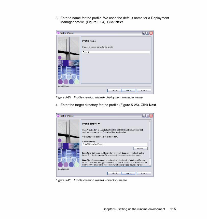
3. Enter a name for the profile. We used the default name for a Deployment Manager profile. (Figure 5-24). Click Next.
Figure 5-24 Profile creation wizard- deployment manager name
4. Enter the target directory for the profile (Figure 5-25). Click Next.
Figure 5-25 Profile creation wizard - directory name
Chapter 5. Setting up the runtime environment 115
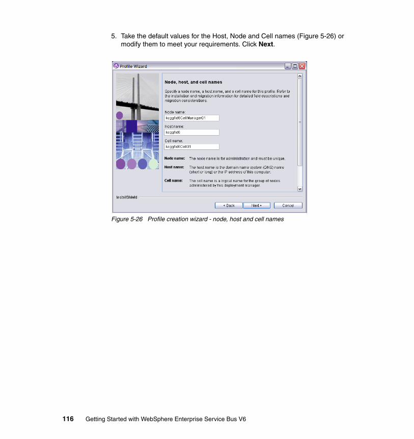
5. Take the default values for the Host, Node and Cell names (Figure 5-26) or modify them to meet your requirements. Click Next.
Figure 5-26 Profile creation wizard - node, host and cell names
116 Getting Started with WebSphere Enterprise Service Bus V6
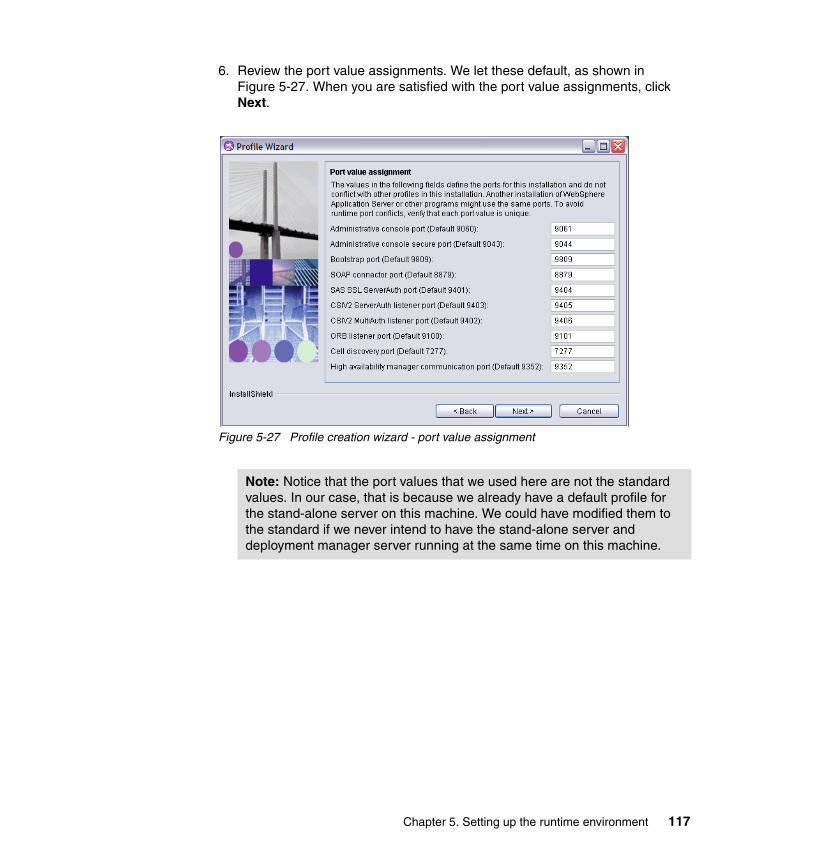
6. Review the port value assignments. We let these default, as shown in Figure 5-27. When you are satisfied with the port value assignments, click Next.
Figure 5-27 Profile creation wizard - port value assignment
Note: Notice that the port values that we used here are not the standard values. In our case, that is because we already have a default profile for the stand-alone server on this machine. We could have modified them to the standard if we never intend to have the stand-alone server and deployment manager server running at the same time on this machine.
Chapter 5. Setting up the runtime environment 117
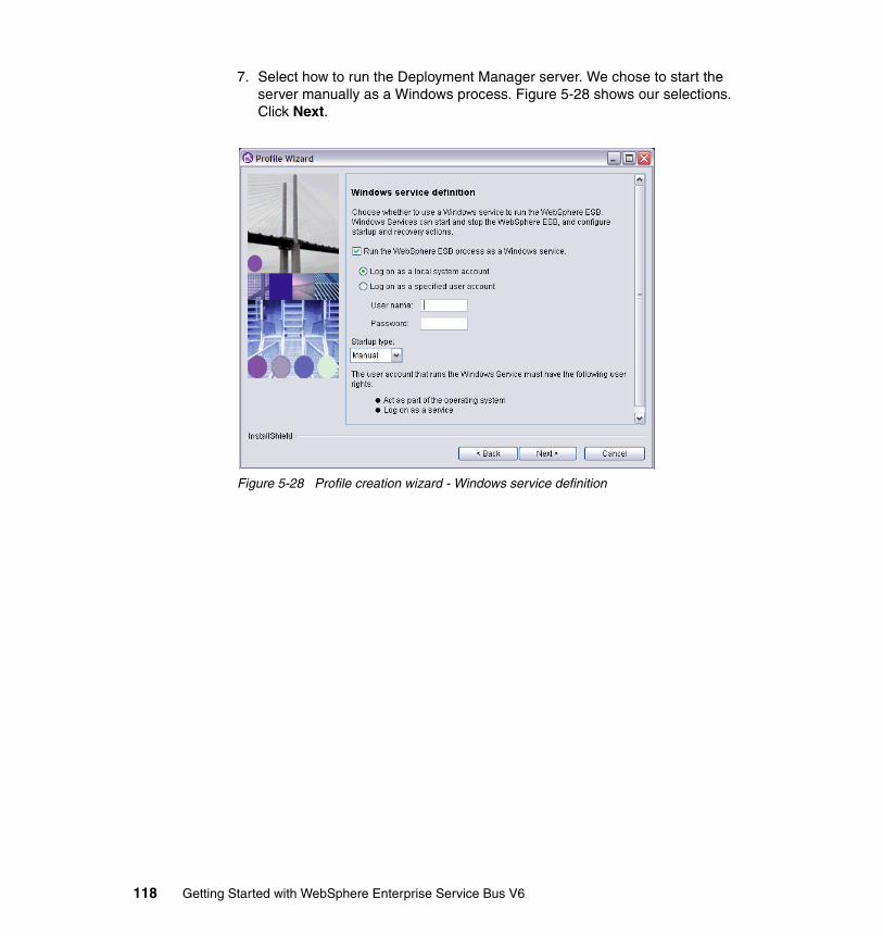
7. Select how to run the Deployment Manager server. We chose to start the server manually as a Windows process. Figure 5-28 shows our selections. Click Next.
Figure 5-28 Profile creation wizard - Windows service definition
118 Getting Started with WebSphere Enterprise Service Bus V6
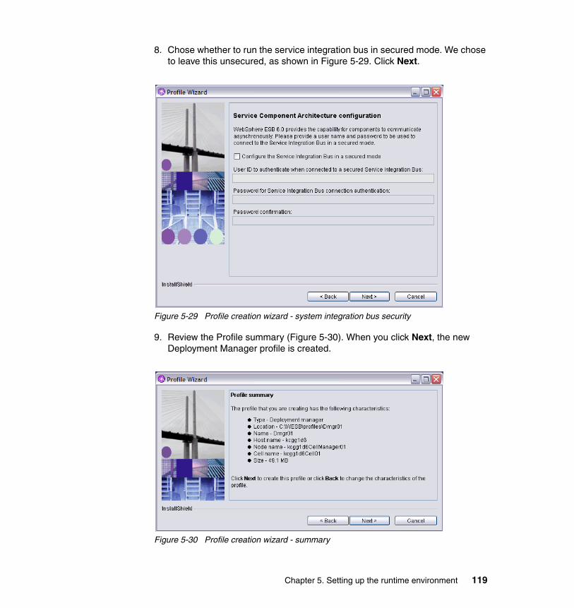
8. Chose whether to run the service integration bus in secured mode. We chose to leave this unsecured, as shown in Figure 5-29. Click Next.
Figure 5-29 Profile creation wizard - system integration bus security
9. Review the Profile summary (Figure 5-30). When you click Next, the new Deployment Manager profile is created.
Figure 5-30 Profile creation wizard - summary
Chapter 5. Setting up the runtime environment 119
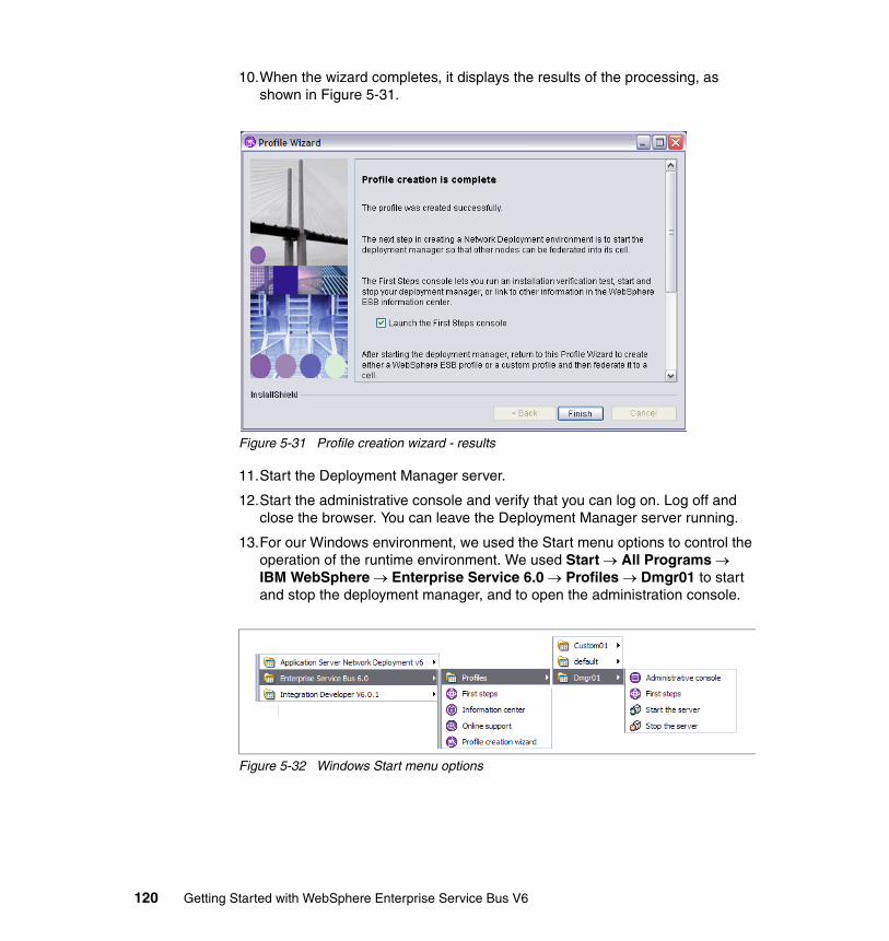
10.When the wizard completes, it displays the results of the processing, as shown in Figure 5-31.
Figure 5-31 Profile creation wizard - results
11.Start the Deployment Manager server.
12.Start the administrative console and verify that you can log on. Log off and close the browser. You can leave the Deployment Manager server running.
13.For our Windows environment, we used the Start menu options to control the operation of the runtime environment. We used Start → All Programs → IBM WebSphere → Enterprise Service 6.0 → Profiles → Dmgr01 to start and stop the deployment manager, and to open the administration console.
Figure 5-32 Windows Start menu options
120 Getting Started with WebSphere Enterprise Service Bus V6
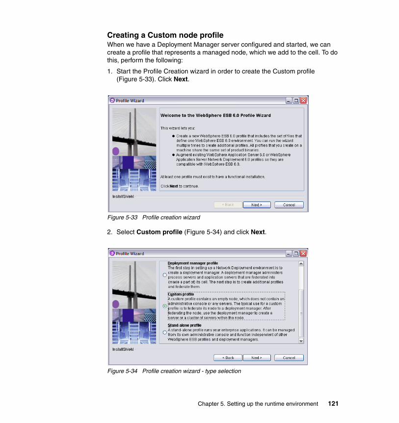
Creating a Custom node profileWhen we have a Deployment Manager server configured and started, we can create a profile that represents a managed node, which we add to the cell. To do this, perform the following:
1. Start the Profile Creation wizard in order to create the Custom profile (Figure 5-33). Click Next.
Figure 5-33 Profile creation wizard
2. Select Custom profile (Figure 5-34) and click Next.
Figure 5-34 Profile creation wizard - type selection
Chapter 5. Setting up the runtime environment 121
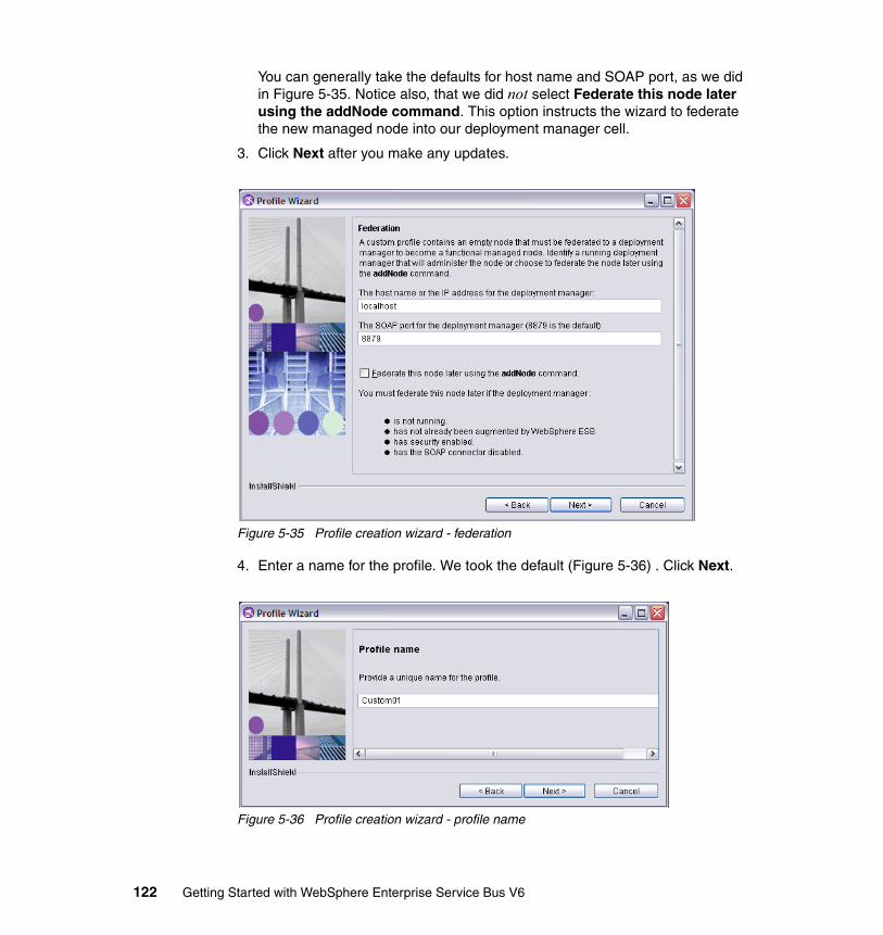
You can generally take the defaults for host name and SOAP port, as we did in Figure 5-35. Notice also, that we did not select Federate this node later using the addNode command. This option instructs the wizard to federate the new managed node into our deployment manager cell.
3. Click Next after you make any updates.
Figure 5-35 Profile creation wizard - federation
4. Enter a name for the profile. We took the default (Figure 5-36) . Click Next.
Figure 5-36 Profile creation wizard - profile name
122 Getting Started with WebSphere Enterprise Service Bus V6
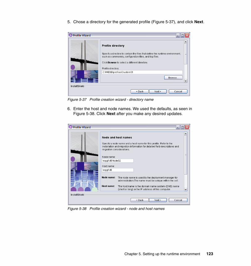
5. Chose a directory for the generated profile (Figure 5-37), and click Next.
Figure 5-37 Profile creation wizard - directory name
6. Enter the host and node names. We used the defaults, as seen in Figure 5-38. Click Next after you make any desired updates.
Figure 5-38 Profile creation wizard - node and host names
Chapter 5. Setting up the runtime environment 123

Click Next and review the port assignments. Notice that we accepted the port assignments that were generated by the wizard, although they are not the default values (Figure 5-39). Because we have a stand-alone server already configured on this machine, the wizard generated port values that would not conflict with that configuration.
7. Click Next.
Figure 5-39 Profile creation wizard - port value assignments
124 Getting Started with WebSphere Enterprise Service Bus V6

8. Review the summary information for accuracy. When you click Next, the profile is created (Figure 5-40).
Figure 5-40 Profile creation wizard - summary
9. The final dialog reports the results of the profile creation, as shown in Figure 5-41. Click Finish when your review is complete.
Figure 5-41 Profile creation wizard - results
10.Now that you have the custom profile created, you should start the node agent for the managed node. In the Windows Explorer, browse to the directory where you created the profile. From there, open the bin directory and find the startNode.bat command file. Run the command to start the node agent.
Chapter 5. Setting up the runtime environment 125
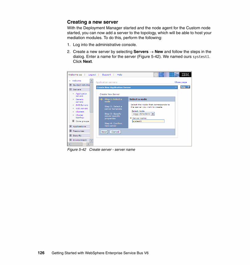
Creating a new serverWith the Deployment Manager started and the node agent for the Custom node started, you can now add a server to the topology, which will be able to host your mediation modules. To do this, perform the following:
1. Log into the administrative console.
2. Create a new server by selecting Servers → New and follow the steps in the dialog. Enter a name for the server (Figure 5-42). We named ours systest1. Click Next.
Figure 5-42 Create server - server name
126 Getting Started with WebSphere Enterprise Service Bus V6
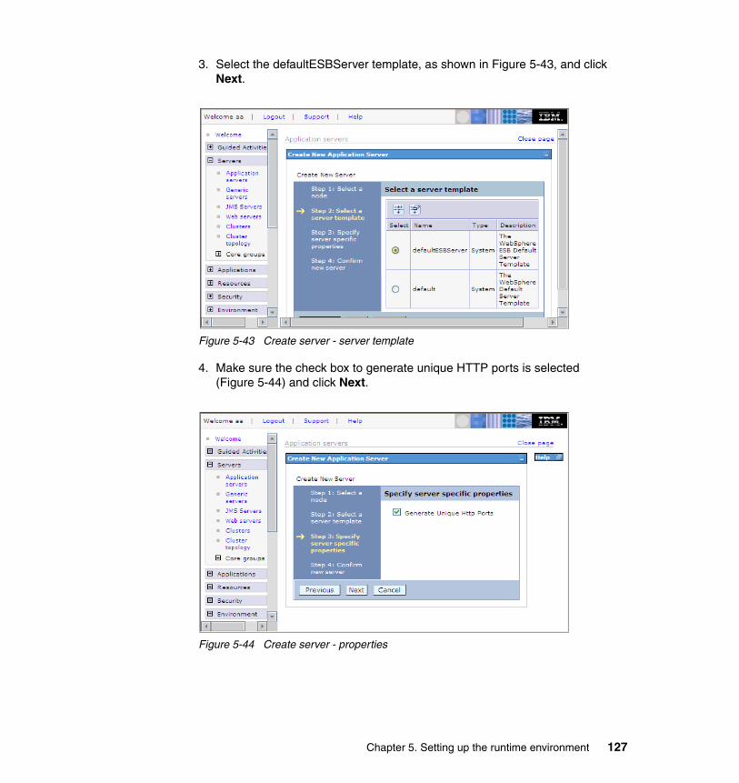
3. Select the defaultESBServer template, as shown in Figure 5-43, and click Next.
Figure 5-43 Create server - server template
4. Make sure the check box to generate unique HTTP ports is selected (Figure 5-44) and click Next.
Figure 5-44 Create server - properties
Chapter 5. Setting up the runtime environment 127
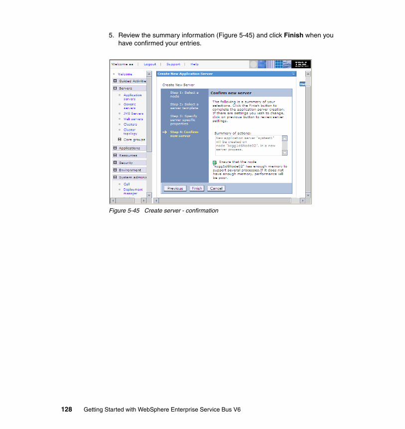
5. Review the summary information (Figure 5-45) and click Finish when you have confirmed your entries.
Figure 5-45 Create server - confirmation
128 Getting Started with WebSphere Enterprise Service Bus V6
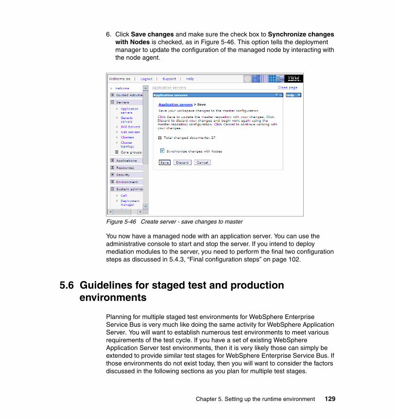
6. Click Save changes and make sure the check box to Synchronize changes with Nodes is checked, as in Figure 5-46. This option tells the deployment manager to update the configuration of the managed node by interacting with the node agent.
Figure 5-46 Create server - save changes to master
You now have a managed node with an application server. You can use the administrative console to start and stop the server. If you intend to deploy mediation modules to the server, you need to perform the final two configuration steps as discussed in 5.4.3, “Final configuration steps” on page 102.
5.6 Guidelines for staged test and production environments
Planning for multiple staged test environments for WebSphere Enterprise Service Bus is very much like doing the same activity for WebSphere Application Server. You will want to establish numerous test environments to meet various requirements of the test cycle. If you have a set of existing WebSphere Application Server test environments, then it is very likely those can simply be extended to provide similar test stages for WebSphere Enterprise Service Bus. If those environments do not exist today, then you will want to consider the factors discussed in the following sections as you plan for multiple test stages.
Chapter 5. Setting up the runtime environment 129
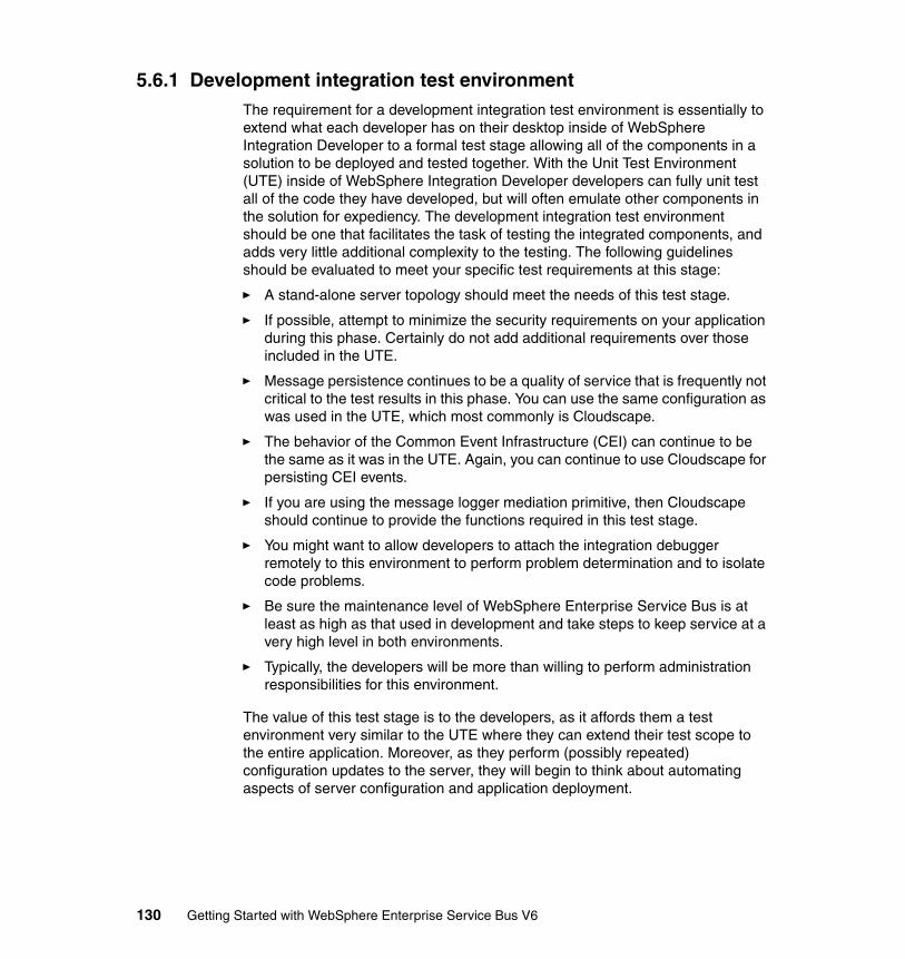
5.6.1 Development integration test environmentThe requirement for a development integration test environment is essentially to extend what each developer has on their desktop inside of WebSphere Integration Developer to a formal test stage allowing all of the components in a solution to be deployed and tested together. With the Unit Test Environment (UTE) inside of WebSphere Integration Developer developers can fully unit test all of the code they have developed, but will often emulate other components in the solution for expediency. The development integration test environment should be one that facilitates the task of testing the integrated components, and adds very little additional complexity to the testing. The following guidelines should be evaluated to meet your specific test requirements at this stage:
� A stand-alone server topology should meet the needs of this test stage.
� If possible, attempt to minimize the security requirements on your application during this phase. Certainly do not add additional requirements over those included in the UTE.
� Message persistence continues to be a quality of service that is frequently not critical to the test results in this phase. You can use the same configuration as was used in the UTE, which most commonly is Cloudscape.
� The behavior of the Common Event Infrastructure (CEI) can continue to be the same as it was in the UTE. Again, you can continue to use Cloudscape for persisting CEI events.
� If you are using the message logger mediation primitive, then Cloudscape should continue to provide the functions required in this test stage.
� You might want to allow developers to attach the integration debugger remotely to this environment to perform problem determination and to isolate code problems.
� Be sure the maintenance level of WebSphere Enterprise Service Bus is at least as high as that used in development and take steps to keep service at a very high level in both environments.
� Typically, the developers will be more than willing to perform administration responsibilities for this environment.
The value of this test stage is to the developers, as it affords them a test environment very similar to the UTE where they can extend their test scope to the entire application. Moreover, as they perform (possibly repeated) configuration updates to the server, they will begin to think about automating aspects of server configuration and application deployment.
130 Getting Started with WebSphere Enterprise Service Bus V6
5.6.2 System test environmentMoving to a system test environment begins to introduce many of the complexities of a real production environment, with perhaps the exception of scale. The application is now tested at a functional level and all of its components have been tested in the packaging scheme that is likely to exist in a production environment. So the requirements of this test stage are more those of moving the runtime toward a real production environment. The testing includes a higher load than was applied in the prior test phase, and many of the test cases dealing with security, failure, and recovery can only be attempted now for the first time.
Consider the following:
� A Network Deployment topology will most likely be required because the need to administer the cell from a single point of control will probably be a high priority. Also, the throughput requirements might be such that a single messaging engine cannot handle the load.
� Global security should be turned on for the cell to control access to the administrative console as well as to perform test cases dealing with authentication and authorized access to parts of the application.
� Message persistence should be configured to use a relational data store, such as DB2® Universal Database™. Also, the default settings for persistence might need to be modified to represent production requirements. Losing messages in a production environment is rarely acceptable.
� If the CEI events are to be enabled, then a relational database should be configured for these as well.
� There will be a need to run various utilities against the newly defined databases in this environment. For example, clean-up utilities might need to be run against the CEI database. Scripts are provided for DB2 Universal Database V8.1 and V8.2.1 which invoke the runstats and reorg DB2 utilities. Use runstats to update the database statistics after a large number of records have been purged from the database, or inserted into it. Also, after using the reorg script or adding/removing indexes from a table, runstats should be executed. The scripts are found in the install_root/event/dbscripts/db2 directory.
� Configure a relational database datasource if your mediation modules are using the logger primitive.
� Consider using automated scripts to configure the servers and deploy the applications into this test stage to make sure they will support the production environment.
� Use the problem determination facilities of your application and the WebSphere Enterprise Service Bus runtime to isolate problems.
Chapter 5. Setting up the runtime environment 131
� Consider modifying the configuration of the queue points and activation specification options to enable them to sustain higher loads.
� Consider configuring additional bus topologies, for example a foreign bus or MQLink to an existing WebSphere MQ network. A service integration bus must be wholly contained in a single cell. You can, however have more than one bus in a cell and you can connect buses with a foreign link whether they are in the same cell or different cells.
� The maintenance level of WebSphere Enterprise Service Bus should be the same as the maintenance level used to exit development integration testing, although service might not be applied as frequently to this environment.
The system test environment is intended to support all of the possible test cases developed for the application.
5.6.3 Quality assurance environmentThe QA environment is often configured to match as closely as possible the actual production environment. With the exception that the databases and back-end systems accessed will still not be those used for production, virtually everything else should be identical. This environment is commonly used for early user testing and frequently used to measure application performance, throughput and end user response time.
Generally this environment is built to scale in the same manner as a production environment, so the size and number of servers configured should match very closely with those in production. The configuration can be enhanced over that used in a system test environment to allow for additional clustering, fail-over, and workload balancing.
The maintenance level of WebSphere Enterprise Service Bus in this environment should match that on which system testing exited. Most often the maintenance level will match that being used in production with the possible exception of some very small windows where service updates are applied here and quick regression testing is done, prior to the service being rolled into production.
132 Getting Started with WebSphere Enterprise Service Bus V6
5.7 Problem determination for runtime installation and customization
Although the wizards that direct you through initial product installation and customization worked well for us, there might be cases where you encounter problems in your environment. For help in identifying the cause of an installation or customization failure, see:
http://publib.boulder.ibm.com/infocenter/dmndhelp/v6rxmx/index.jsp
Under the topic Installing is the subtopic Troubleshooting installation, which should help you through the problem determination steps.
Generally problem determination is broken down into three basic areas, as follows:
� Did installation of WebSphere Application Server Network Deployment complete successfully?
� Did installation of WebSphere Enterprise Service Bus complete successfully?
� Did profile creation or augmentation complete successfully?
The tasks you perform to do problem determination depend on which of these three activities caused the problem.
In general, you should understand that each of the installation and customization steps you perform has associated with it a set of logs that capture the events that occur during that phase. If you can find the log file that contains the events that were being processed during the portion of installation or customization which failed, you should browse it to see if you can determine the error. The logs, however, are not all that easy to read or interpret, so if you find they are not helpful, you should contact IBM support to help diagnose your problem. The support team will most likely request the logs, so be sure you can find them and that they correspond to the state of the installation that was known to have the error.
As always, paying careful attention to the system prerequisites can help to avoid installation problems, and when provided, always capture error messages that appear at the user interface.
Chapter 5. Setting up the runtime environment 133

134 Getting Started with WebSphere Enterprise Service Bus V6
Chapter 6. WebSphere Enterprise Service Bus key concepts and related technologies
This chapter explains the key concepts of WebSphere Enterprise Service Bus and explores some of the most important related technologies. First, we give a short feature overview of the product and explain the key terms. Then, we break down the product structure in a top-down fashion. Finally, we discuss the following complementary technology viewpoints:
� The data view (Service Data Objects)� The external interfaces view (Bindings)� The system management view (Common Event Infrastructure)� The deployment view
6
© Copyright IBM Corp. 2006. All rights reserved. 135
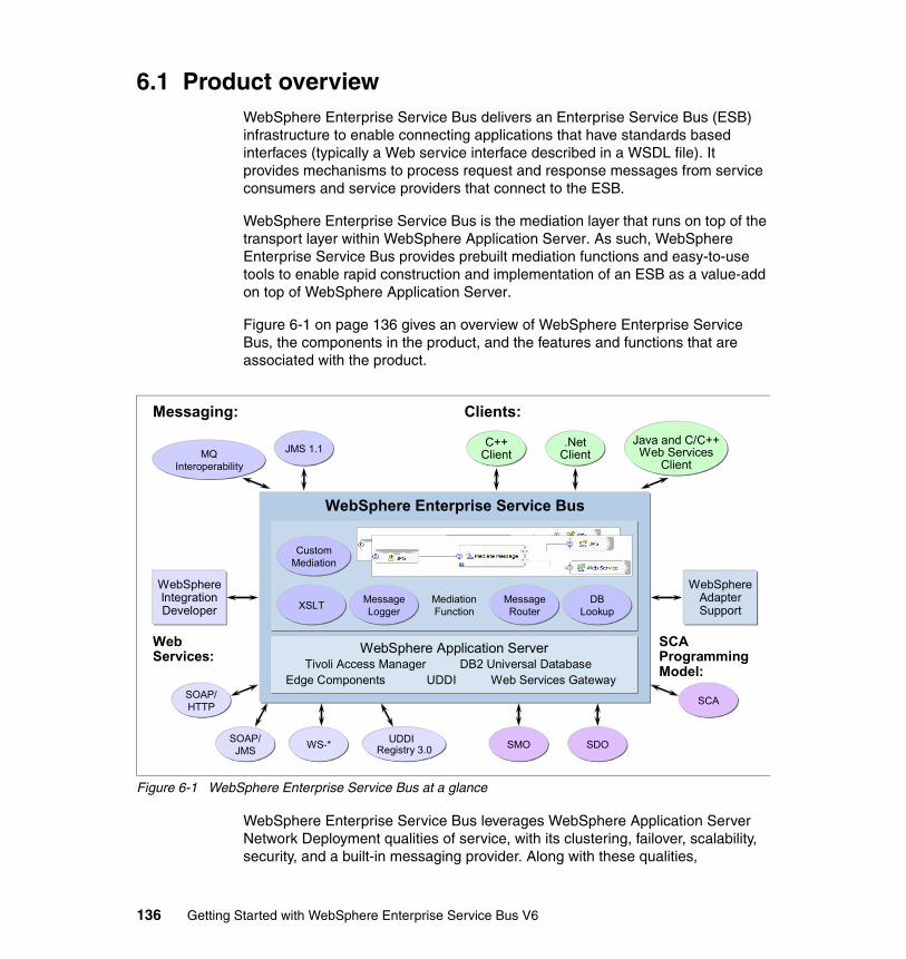
6.1 Product overviewWebSphere Enterprise Service Bus delivers an Enterprise Service Bus (ESB) infrastructure to enable connecting applications that have standards based interfaces (typically a Web service interface described in a WSDL file). It provides mechanisms to process request and response messages from service consumers and service providers that connect to the ESB.
WebSphere Enterprise Service Bus is the mediation layer that runs on top of the transport layer within WebSphere Application Server. As such, WebSphere Enterprise Service Bus provides prebuilt mediation functions and easy-to-use tools to enable rapid construction and implementation of an ESB as a value-add on top of WebSphere Application Server.
Figure 6-1 on page 136 gives an overview of WebSphere Enterprise Service Bus, the components in the product, and the features and functions that are associated with the product.
Figure 6-1 WebSphere Enterprise Service Bus at a glance
WebSphere Enterprise Service Bus leverages WebSphere Application Server Network Deployment qualities of service, with its clustering, failover, scalability, security, and a built-in messaging provider. Along with these qualities,
WebSphere Enterprise Service Bus
Mediation Function
CustomMediation
XSLT MessageLogger
MessageRouter
DBLookup
WebSphere Application ServerTivoli Access Manager
Edge Components UDDIDB2 Universal Database
Web Services GatewaySOAP/HTTP
SOAP/JMS WS-* UDDI
Registry 3.0 SMO SDO
SCA
MQInteroperability
JMS 1.1 C++Client
.NetClient
Java and C/C++Web Services
Client
WebSphereIntegrationDeveloper
WebSphereAdapterSupport
Clients:Messaging:
Web Services:
SCAProgrammingModel:
136 Getting Started with WebSphere Enterprise Service Bus V6
WebSphere Enterprise Service Bus includes a number of key WebSphere Application Server related features, including UDDI as a service registry, the Web services gateway, Tivoli® Access Manager, DB2 Universal Database, and Edge components.
WebSphere Enterprise Service Bus adds the following value to the application server:
� Provides built-in mediation functions, which can be used to create integration logic for connectivity.
� The SCA programming model supports rapid development of mediation flow components.
� WebSphere Integration Developer is an easy-to-use tool that supports WebSphere Enterprise Service Bus.
� Leveraging WebSphere Application Server, WebSphere Enterprise Service Bus offers JMS messaging and WebSphere MQ interoperability for messaging, as well as a comprehensive clients package for connectivity.
� Offers support for J2EE Connector Architecture based WebSphere Adapters.
To implement an SOA properly, it is necessary to have a single invocation model and a single data model. Service Component Architecture (SCA) is this invocation model — every integration component is described through an interface. These services can then be assembled in a component assembly editor thus enabling a very flexible and encapsulated solution.
WebSphere Enterprise Service Bus introduces a new component type to the SCA model — the mediation flow component. From the perspective of the SCA, a mediation flow component is not different to any other service component.
Business Objects are the universal data description. They are used as data objects are passed between services and are based on the Service Data Object (SDO) standard. In WebSphere Enterprise Service Bus a special type of SDO is introduced, the Service Message Object (SMO).
Also part of the infrastructure is the Common Event Infrastructure (CEI), which is the foundation for monitoring applications. IBM uses this infrastructure throughout its product portfolio, and monitoring products from Tivoli as well as WebSphere Business Monitor exploit it. The event definition (Common Business Event) is standardized through the OASIS standards body, so that other companies as well as customers can use the same infrastructure to monitor their environment.
Chapter 6. WebSphere Enterprise Service Bus key concepts and related technologies 137
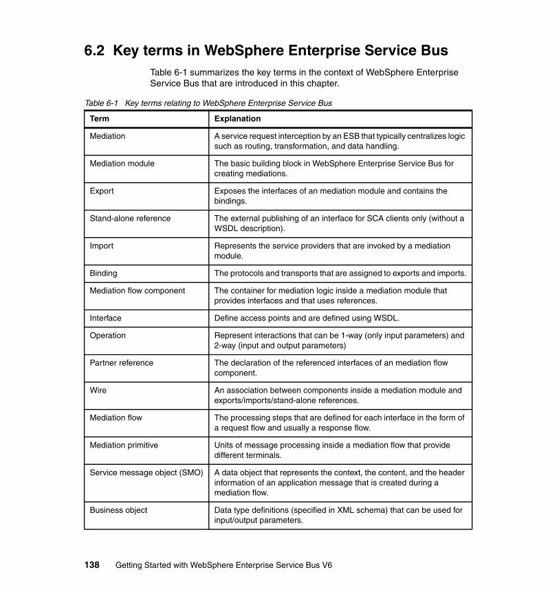
6.2 Key terms in WebSphere Enterprise Service BusTable 6-1 summarizes the key terms in the context of WebSphere Enterprise Service Bus that are introduced in this chapter.
Table 6-1 Key terms relating to WebSphere Enterprise Service Bus
Term Explanation
Mediation A service request interception by an ESB that typically centralizes logic such as routing, transformation, and data handling.
Mediation module The basic building block in WebSphere Enterprise Service Bus for creating mediations.
Export Exposes the interfaces of an mediation module and contains the bindings.
Stand-alone reference The external publishing of an interface for SCA clients only (without a WSDL description).
Import Represents the service providers that are invoked by a mediation module.
Binding The protocols and transports that are assigned to exports and imports.
Mediation flow component The container for mediation logic inside a mediation module that provides interfaces and that uses references.
Interface Define access points and are defined using WSDL.
Operation Represent interactions that can be 1-way (only input parameters) and 2-way (input and output parameters)
Partner reference The declaration of the referenced interfaces of an mediation flow component.
Wire An association between components inside a mediation module and exports/imports/stand-alone references.
Mediation flow The processing steps that are defined for each interface in the form of a request flow and usually a response flow.
Mediation primitive Units of message processing inside a mediation flow that provide different terminals.
Service message object (SMO) A data object that represents the context, the content, and the header information of an application message that is created during a mediation flow.
Business object Data type definitions (specified in XML schema) that can be used for input/output parameters.
138 Getting Started with WebSphere Enterprise Service Bus V6

6.3 Structure of WebSphere Enterprise Service BusThis section explores the structure of WebSphere Enterprise Service Bus by working through the different layers of the product architecture in a top-down manner.
6.3.1 Mediations, service consumers, and service providersA service interaction in SOA defines both service consumers and service providers. The role of WebSphere Enterprise Service Bus is to intercept the requests of service consumers and fulfill additional tasks in mediations in order to support loose coupling. When the mediation completes, the relevant service provider(s) should be invoked. The mediation tasks include:
� Centralizing the routing logic so that service providers can be exchanged transparently
� Performing tasks like protocol translation and transport mapping
� Acting as a facade in order to provide different interfaces between service consumers and providers
� Adding logic to provide tasks such as logging
As shown in Figure 6-2 mediations customize the protocol and the details of a request and also modify the results of the reply.
Figure 6-2 Enterprise Service Bus and mediations
Chapter 6. WebSphere Enterprise Service Bus key concepts and related technologies 139
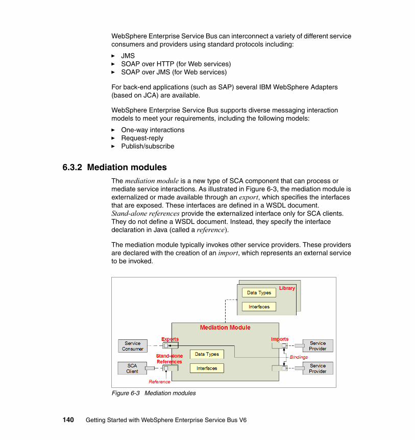
WebSphere Enterprise Service Bus can interconnect a variety of different service consumers and providers using standard protocols including:
� JMS� SOAP over HTTP (for Web services)� SOAP over JMS (for Web services)
For back-end applications (such as SAP) several IBM WebSphere Adapters (based on JCA) are available.
WebSphere Enterprise Service Bus supports diverse messaging interaction models to meet your requirements, including the following models:
� One-way interactions� Request-reply� Publish/subscribe
6.3.2 Mediation modulesThe mediation module is a new type of SCA component that can process or mediate service interactions. As illustrated in Figure 6-3, the mediation module is externalized or made available through an export, which specifies the interfaces that are exposed. These interfaces are defined in a WSDL document. Stand-alone references provide the externalized interface only for SCA clients. They do not define a WSDL document. Instead, they specify the interface declaration in Java (called a reference).
The mediation module typically invokes other service providers. These providers are declared with the creation of an import, which represents an external service to be invoked.
Figure 6-3 Mediation modules
140 Getting Started with WebSphere Enterprise Service Bus V6
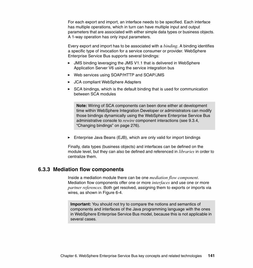
For each export and import, an interface needs to be specified. Each interface has multiple operations, which in turn can have multiple input and output parameters that are associated with either simple data types or business objects. A 1-way operation has only input parameters.
Every export and import has to be associated with a binding. A binding identifies a specific type of invocation for a service consumer or provider. WebSphere Enterprise Service Bus supports several bindings:
� JMS binding leveraging the JMS V1.1 that is delivered in WebSphere Application Server V6 using the service integration bus
� Web services using SOAP/HTTP and SOAP/JMS
� JCA compliant WebSphere Adapters
� SCA bindings, which is the default binding that is used for communication between SCA modules
� Enterprise Java Beans (EJB), which are only valid for import bindings
Finally, data types (business objects) and interfaces can be defined on the module level, but they can also be defined and referenced in libraries in order to centralize them.
6.3.3 Mediation flow componentsInside a mediation module there can be one mediation flow component. Mediation flow components offer one or more interfaces and use one or more partner references. Both get resolved, assigning them to exports or imports via wires, as shown in Figure 6-4.
Note: Wiring of SCA components can been done either at development time within WebSphere Integration Developer or administrators can modify those bindings dynamically using the WebSphere Enterprise Service Bus administrative console to rewire component interactions (see 9.3.4, “Changing bindings” on page 276).
Important: You should not try to compare the notions and semantics of components and interfaces of the Java programming language with the ones in WebSphere Enterprise Service Bus model, because this is not applicable in several cases.
Chapter 6. WebSphere Enterprise Service Bus key concepts and related technologies 141
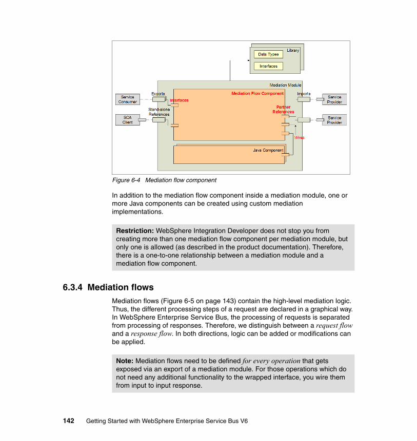
Figure 6-4 Mediation flow component
In addition to the mediation flow component inside a mediation module, one or more Java components can be created using custom mediation implementations.
6.3.4 Mediation flowsMediation flows (Figure 6-5 on page 143) contain the high-level mediation logic. Thus, the different processing steps of a request are declared in a graphical way. In WebSphere Enterprise Service Bus, the processing of requests is separated from processing of responses. Therefore, we distinguish between a request flow and a response flow. In both directions, logic can be added or modifications can be applied.
Restriction: WebSphere Integration Developer does not stop you from creating more than one mediation flow component per mediation module, but only one is allowed (as described in the product documentation). Therefore, there is a one-to-one relationship between a mediation module and a mediation flow component.
Note: Mediation flows need to be defined for every operation that gets exposed via an export of a mediation module. For those operations which do not need any additional functionality to the wrapped interface, you wire them from input to input response.
142 Getting Started with WebSphere Enterprise Service Bus V6
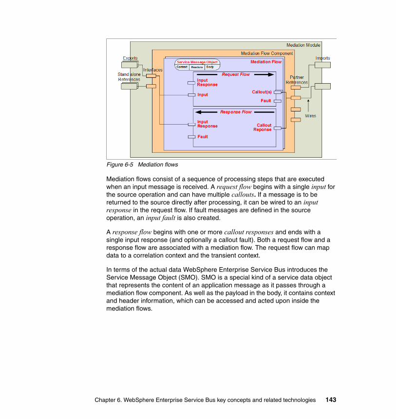
Figure 6-5 Mediation flows
Mediation flows consist of a sequence of processing steps that are executed when an input message is received. A request flow begins with a single input for the source operation and can have multiple callouts. If a message is to be returned to the source directly after processing, it can be wired to an input response in the request flow. If fault messages are defined in the source operation, an input fault is also created.
A response flow begins with one or more callout responses and ends with a single input response (and optionally a callout fault). Both a request flow and a response flow are associated with a mediation flow. The request flow can map data to a correlation context and the transient context.
In terms of the actual data WebSphere Enterprise Service Bus introduces the Service Message Object (SMO). SMO is a special kind of a service data object that represents the content of an application message as it passes through a mediation flow component. As well as the payload in the body, it contains context and header information, which can be accessed and acted upon inside the mediation flows.
Chapter 6. WebSphere Enterprise Service Bus key concepts and related technologies 143
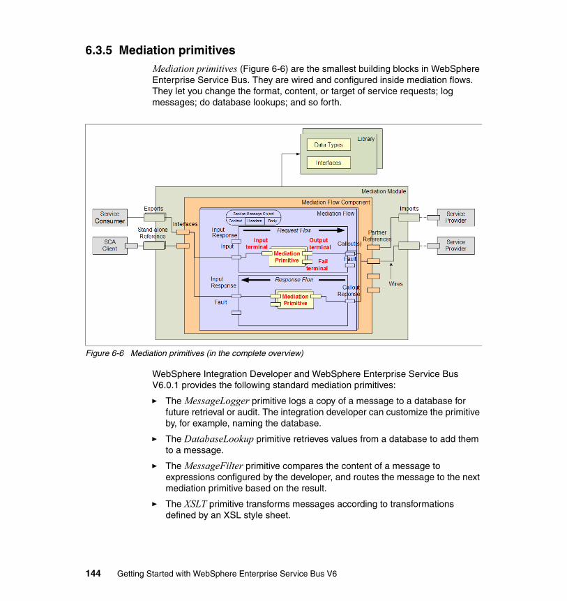
6.3.5 Mediation primitivesMediation primitives (Figure 6-6) are the smallest building blocks in WebSphere Enterprise Service Bus. They are wired and configured inside mediation flows. They let you change the format, content, or target of service requests; log messages; do database lookups; and so forth.
Figure 6-6 Mediation primitives (in the complete overview)
WebSphere Integration Developer and WebSphere Enterprise Service Bus V6.0.1 provides the following standard mediation primitives:
� The MessageLogger primitive logs a copy of a message to a database for future retrieval or audit. The integration developer can customize the primitive by, for example, naming the database.
� The DatabaseLookup primitive retrieves values from a database to add them to a message.
� The MessageFilter primitive compares the content of a message to expressions configured by the developer, and routes the message to the next mediation primitive based on the result.
� The XSLT primitive transforms messages according to transformations defined by an XSL style sheet.
144 Getting Started with WebSphere Enterprise Service Bus V6
� The Fail primitive throws an exception and terminates the path through the mediation flow.
� The Stop primitive silently terminates the path through the mediation flow.
� The Custom mediation primitive allows the user to implement their own mediate method using Java. The Custom mediation, like the other primitives, receives a Service Message Object and returns a Service Message Object. It can be used to perform tasks that cannot be performed by using the other mediation primitives.
Mediation primitives have three types of terminal:
� In terminal: All mediation primitives have an in terminal that can be wired to accept a message.
� Out terminal: Most mediation primitives have one or more out terminals that can be wired to propagate a message (exceptions are the stop and the fail primitive).
� Fault terminal: If an exception occurs during the processing of an input message, then the fail terminal propagates the original message, together with any exception information.
6.4 Related technologiesThis section explores some of the accompanying features of WebSphere Enterprise Service Bus in more detail.
6.4.1 Service message objectsMessages can come from a variety of sources, so the payload has to be able to carry a number of different types of messages. Mediation primitives need to be able to operate on these messages, and service message objects (SMOs) represents the common representation that is needed.
The types of messages that are handled by WebSphere Enterprise Service Bus include:
� SDO data object� SDO data graph� SCA component invocation message (request, reply or exception)� SOAP message� JMS message
Chapter 6. WebSphere Enterprise Service Bus key concepts and related technologies 145
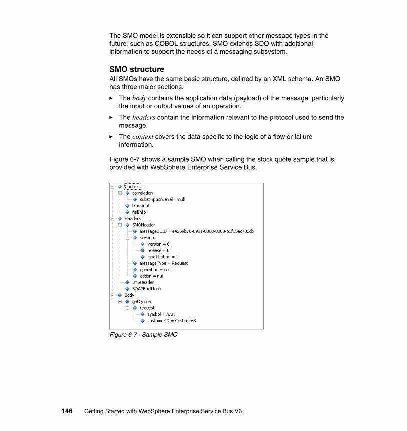
The SMO model is extensible so it can support other message types in the future, such as COBOL structures. SMO extends SDO with additional information to support the needs of a messaging subsystem.
SMO structureAll SMOs have the same basic structure, defined by an XML schema. An SMO has three major sections:
� The body contains the application data (payload) of the message, particularly the input or output values of an operation.
� The headers contain the information relevant to the protocol used to send the message.
� The context covers the data specific to the logic of a flow or failure information.
Figure 6-7 shows a sample SMO when calling the stock quote sample that is provided with WebSphere Enterprise Service Bus.
Figure 6-7 Sample SMO
146 Getting Started with WebSphere Enterprise Service Bus V6
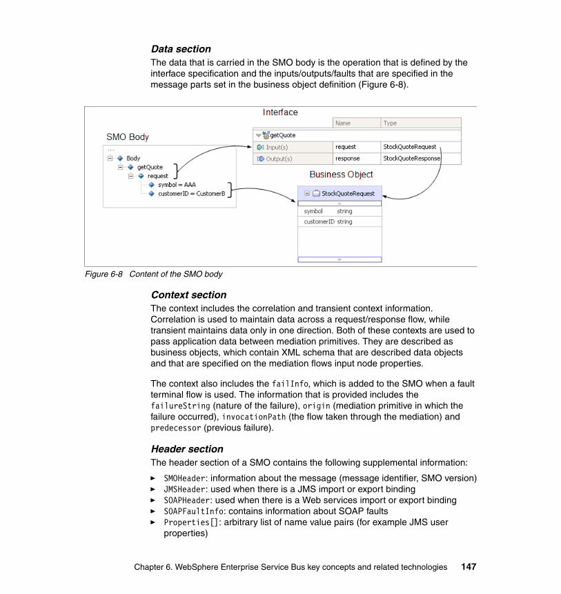
Data sectionThe data that is carried in the SMO body is the operation that is defined by the interface specification and the inputs/outputs/faults that are specified in the message parts set in the business object definition (Figure 6-8).
Figure 6-8 Content of the SMO body
Context sectionThe context includes the correlation and transient context information. Correlation is used to maintain data across a request/response flow, while transient maintains data only in one direction. Both of these contexts are used to pass application data between mediation primitives. They are described as business objects, which contain XML schema that are described data objects and that are specified on the mediation flows input node properties.
The context also includes the failInfo, which is added to the SMO when a fault terminal flow is used. The information that is provided includes the failureString (nature of the failure), origin (mediation primitive in which the failure occurred), invocationPath (the flow taken through the mediation) and predecessor (previous failure).
Header sectionThe header section of a SMO contains the following supplemental information:
� SMOHeader: information about the message (message identifier, SMO version)� JMSHeader: used when there is a JMS import or export binding� SOAPHeader: used when there is a Web services import or export binding� SOAPFaultInfo: contains information about SOAP faults� Properties[]: arbitrary list of name value pairs (for example JMS user
properties)
Chapter 6. WebSphere Enterprise Service Bus key concepts and related technologies 147
SMO manipulationDuring the execution of mediation flows the active mediation primitives can access and manipulate the SMO. There are three different ways to access SMOs:
� XPath V1.0 expressions
The primary mechanism that is used by all mediation primitives.
� XSL stylesheets
Used by the XSLT mediation primitive and are the common way to modify the SMO type within a flow. It can also be used to modify the SMO without changing the type (using XSLT function and logical processing with XSL choose statements).
� Java code
Using the Custom Mediation primitive, you can access the SMO either using the generic DataObject APIs (commonj.sdo.DataObject, which is loosely typed) or the SMO APIs (com.ibm.websphere.sibx.smobo, strongly typed).
6.4.2 WebSphere Enterprise Service Bus bindingsBindings identify a specific type of invocation for a service consumer or provider. Bindings can be applied to mediation module imports or exports. Exports let a mediation module offer a service to consumers. They define interactions between SCA modules and service consumers. Export bindings define the specific way that an SCA module is accessed by others.
Imports let a mediation module access external services (services that are outside the SCA module) in a transparent manner. Imports define interactions between SCA modules and service providers. Import bindings define the specific way that an external service is accessed.
WebSphere Enterprise Service Bus supports the following bindings:
� Web service binding
Using a Web service binding on an export it exposes the module as a Web service. To invoke an external Web service an import with a Web service binding is used. This binding always uses SOAP messages and two transports are available:
– SOAP/HTTP– SOAP/JMS
� SCA binding
– SCA bindings connect SCA modules with each other.– This is the default binding.
148 Getting Started with WebSphere Enterprise Service Bus V6
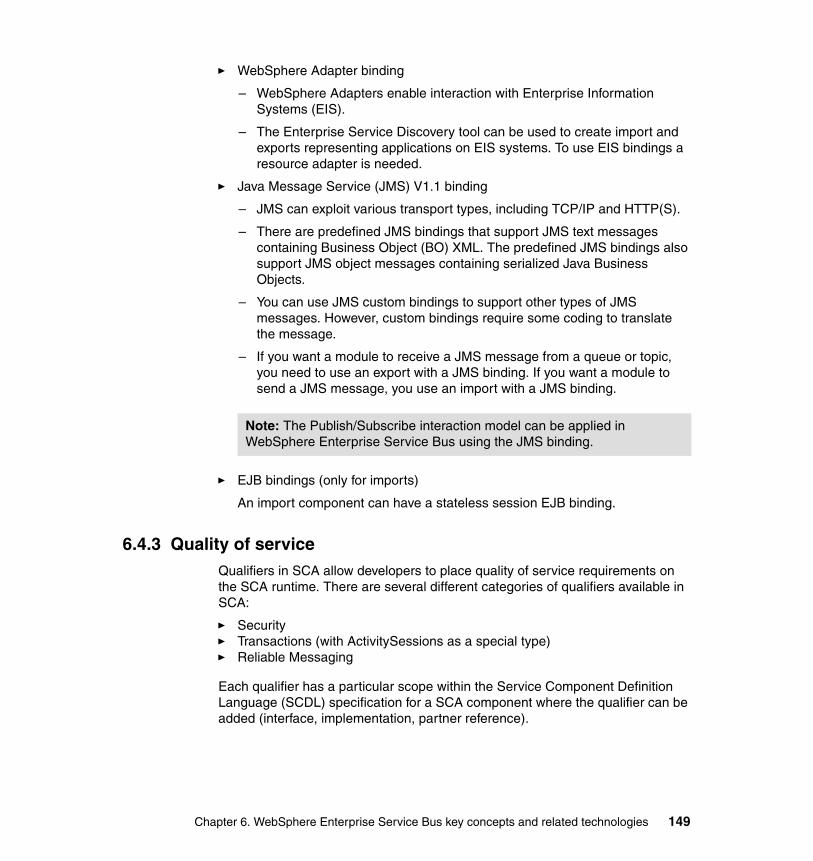
� WebSphere Adapter binding
– WebSphere Adapters enable interaction with Enterprise Information Systems (EIS).
– The Enterprise Service Discovery tool can be used to create import and exports representing applications on EIS systems. To use EIS bindings a resource adapter is needed.
� Java Message Service (JMS) V1.1 binding
– JMS can exploit various transport types, including TCP/IP and HTTP(S).
– There are predefined JMS bindings that support JMS text messages containing Business Object (BO) XML. The predefined JMS bindings also support JMS object messages containing serialized Java Business Objects.
– You can use JMS custom bindings to support other types of JMS messages. However, custom bindings require some coding to translate the message.
– If you want a module to receive a JMS message from a queue or topic, you need to use an export with a JMS binding. If you want a module to send a JMS message, you use an import with a JMS binding.
� EJB bindings (only for imports)
An import component can have a stateless session EJB binding.
6.4.3 Quality of serviceQualifiers in SCA allow developers to place quality of service requirements on the SCA runtime. There are several different categories of qualifiers available in SCA:
� Security� Transactions (with ActivitySessions as a special type)� Reliable Messaging
Each qualifier has a particular scope within the Service Component Definition Language (SCDL) specification for a SCA component where the qualifier can be added (interface, implementation, partner reference).
Note: The Publish/Subscribe interaction model can be applied in WebSphere Enterprise Service Bus using the JMS binding.
Chapter 6. WebSphere Enterprise Service Bus key concepts and related technologies 149
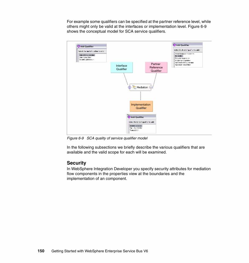
For example some qualifiers can be specified at the partner reference level, while others might only be valid at the interfaces or implementation level. Figure 6-9 shows the conceptual model for SCA service qualifiers.
Figure 6-9 SCA quality of service qualifier model
In the following subsections we briefly describe the various qualifiers that are available and the valid scope for each will be examined.
SecurityIn WebSphere Integration Developer you specify security attributes for mediation flow components in the properties view at the boundaries and the implementation of an component.
Partner ReferenceQualifier
InterfaceQualifier
Implementation Qualifier
150 Getting Started with WebSphere Enterprise Service Bus V6
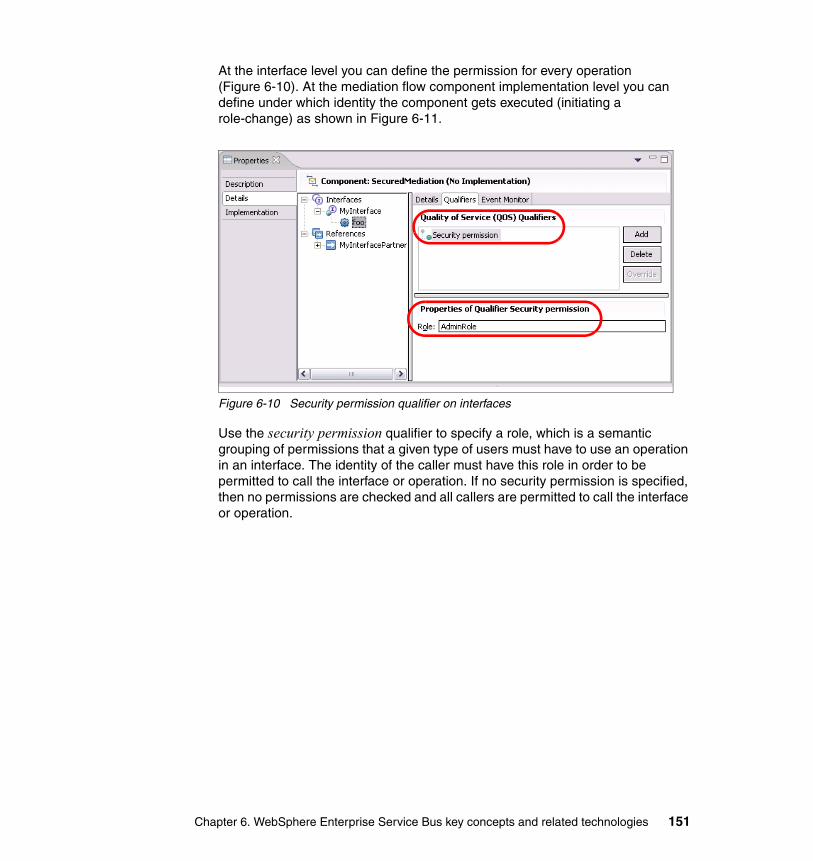
At the interface level you can define the permission for every operation (Figure 6-10). At the mediation flow component implementation level you can define under which identity the component gets executed (initiating a role-change) as shown in Figure 6-11.
Figure 6-10 Security permission qualifier on interfaces
Use the security permission qualifier to specify a role, which is a semantic grouping of permissions that a given type of users must have to use an operation in an interface. The identity of the caller must have this role in order to be permitted to call the interface or operation. If no security permission is specified, then no permissions are checked and all callers are permitted to call the interface or operation.
Chapter 6. WebSphere Enterprise Service Bus key concepts and related technologies 151

The security identity qualifier is a privilege specification that you can use to provide a logical name for the identity under which the implementation executes at run time (Figure 6-11). An implementation has to be created for this qualifier to be specified. If this qualifier is not specified, then the implementation executes under the identity of its caller. Alternatively it is executed under the hosting container’s identity if no caller identity is present. Roles are associated with the identity and the roles dictate whether the implementation is authorized to invoke other components.
Figure 6-11 Security identity qualifier for mediation components
Depending on the bindings you have created, WebSphere Enterprise Service Bus will generate the relevant J2EE artifacts. In order to integrate remote clients (for example using the Web service security specifications) with the J2EE application infrastructure, a proper distributed security infrastructure needs to be built. For additional information of securing Web Services, see WebSphere Version 6 Web Services Handbook Development and Deployment, SG24-6461.
152 Getting Started with WebSphere Enterprise Service Bus V6
Activity sessionsThis qualifier determines if the components processing will be executed under an activity session, which provides an alternate unit-of-work scope to the one provided by global transaction contexts. An activity session context can have a longer lifetime global transaction context and can encapsulate global transactions.
You can specify the activity session qualifier at all three levels:
� Interface level
Can optionally join a propagated (client) activity session.
� Implementation level
For the implementation the qualifier specifies if the component can run under an established activity session. The default is that if an activity session has been propagated from the client, the runtime environment will dispatch methods from the component in the activity session. Otherwise, the component will not run under any activity session.
� Partner reference level
By default, activity session context is always propagated to a target component when it is invoked using the synchronous programming model. If the client does not want a target component to federate with the client’s activity session, further qualification of the partner reference is required using the suspend activity session qualifier.
TransactionsThis qualifier determines the logical unit of work that the component processing executes. For a logical unit of work, all of the data modifications made during a transaction are either committed together as a unit or rolled back as a unit.
� On an interface level the join transaction qualifier determines if the hosting container will join any propagated transaction.
Note: Activity sessions are an extension of J2EE that were introduced with WebSphere Application Server V5. For more information, see:
http://publib.boulder.ibm.com/infocenter/wasinfo/v6r0/topic/com.ibm.websphere.base.doc/info/aes/ae/welc6tech_as.html
Chapter 6. WebSphere Enterprise Service Bus key concepts and related technologies 153

� On a implementation level the transaction qualifier can be set either to global (where multiple resource managers are required), local (default) (running in a local transaction) or any (dispatching the global transaction context if existent).
� For a partner reference you can specify the Suspend transaction qualifier, which can be set to false (so the synchronous invocations run completely within any global transaction) and true (where synchronous invocations occur outside any client global transaction).
In addition the asynchronous invocation determines if asynchronous invocations should occur as part of any client transaction. When set to call (default) the asynchronous invocations using the partner reference will occur immediately, while with commit the partner reference will be transacted as part of any client global transaction or extended local transaction which postpones the availability of the request.
Asynchronous reliabilityTo support asynchronous invocation of components, asynchronous reliability qualifiers can be specified for the partner reference only. They take effect when asynchronous programming calls are used by the client to invoke a service. The reliability qualifier specifications are:
� Reliability
The reliability qualifier determines the quality of an asynchronous message delivery. In general, better performance usually means less reliable message delivery. With an assured specification, the client application cannot tolerate the loss of a request or response message. With a best effort specification, the client application can tolerate the possible loss of the request or response message.
� Request expiration (milliseconds)
Request expiration is the length of time after which an asynchronous request will be discarded if it has not been delivered, beginning from the time when the request is issued. Zero denotes an indefinite expiration.
� Response expiration (milliseconds)
Response expiration is the length of time that the runtime environment must retain an asynchronous response or provide a callback, beginning from the time when the request is issued. Zero denotes an indefinite expiration.
Note: The different combinations of the interface and implementation qualifiers define the behavior for the target component. Not all combinations are allowed.
154 Getting Started with WebSphere Enterprise Service Bus V6
6.4.4 Common event infrastructureThe common event infrastructure CEI is a core component of WebSphere Enterprise Service Bus leveraged from WebSphere Application Server and provides facilities for the runtime environment to persistently store and retrieve events from different programming environments. This section briefly introduces the basic event-related concepts:
� Common Event Infrastructure (CEI)� Common Base Events (CBE)
Common Event InfrastructureIn WebSphere Enterprise Service Bus, the CEI is used to provide basic event management services, such as event generation, transmission, persistence, and consumption. CEI was developed to address industry-wide problems in exchanging events between incompatible systems, many of which employed different event infrastructures, event formats, and data stores.
Common Base EventAlthough CEI provides an infrastructure for event management, it does not define the format of events. This is defined by the Common Base Event specification, which provides a standard XML-based format for business events, system events, and performance information. Application developers and administrators can use the Common Base Event specification for structuring and developing event types.
The key concept in the Common Base Event model is the situation, which is any occurrence that happens anywhere in the computing system, such as a user login or a scheduled server shutdown. The Common Base Event model defines a set of standard situation types, such as StartSituation and CreateSituation, that accommodate most of the situations that might arise.
In the Common Base Event model, an event is a structured notification that reports information related to a situation. An event reports three kinds of information:
� The situation that has occurred
� The identity of the affected component
� The identity of the component that is reporting the situation, which might be the same as the affected component
In the WebSphere Integration Developer editors the specification of event monitoring is based on the operation level.
Chapter 6. WebSphere Enterprise Service Bus key concepts and related technologies 155
6.4.5 Deployment of mediationsWebSphere Integration Developer creates J2EE artifacts which are stored in EAR files. Logically, mediation modules can be thought of as one entity. In reality, SCA modules are defined by a number of XML files (stored in one JAR file later on), which are the basis for the generation of the J2EE artifacts.
J2EE staging projectsFor any given module project there will be up to four J2EE staging projects generated with naming conventions that are based on the modules project name (in the following called MyModule). In the Business Integration view of WebSphere Integration Developer you will not be able to see these projects. To view these you will need to change to another perspective such as the J2EE perspective.
A module can implement the following staging projects
� MyModuleApp - the enterprise application staging project
Enterprise application projects contain artifacts and metadata for an entire enterprise application. It includes information such as the name of the EJB projects contained within the enterprise application, and the context root for the Web modules within the enterprise application.
� MyModuleEJB - the EJB staging project
EJB projects contain artifacts and metadata for Enterprise Java Beans. This project holds generated EJBs that represent the runtime artifacts that make components. For example, an SCA export results in a generated stateless session EJB.
� MyModuleEJBClient - the EJB client staging project
EJB Client projects contain artifacts that represent the client-side for the EJBs in the EJB projects. For example they include stubs for remote and home interfaces so that clients of EJBs can interact with the EJBs.
� MyModuleWeb - the dynamic Web staging project
Dynamic Web projects contain artifacts that represent Web components such as servlets and JSPs. In particular the Web project contains a servlet that represents an HTTP router for inbound HTTP traffic.
156 Getting Started with WebSphere Enterprise Service Bus V6
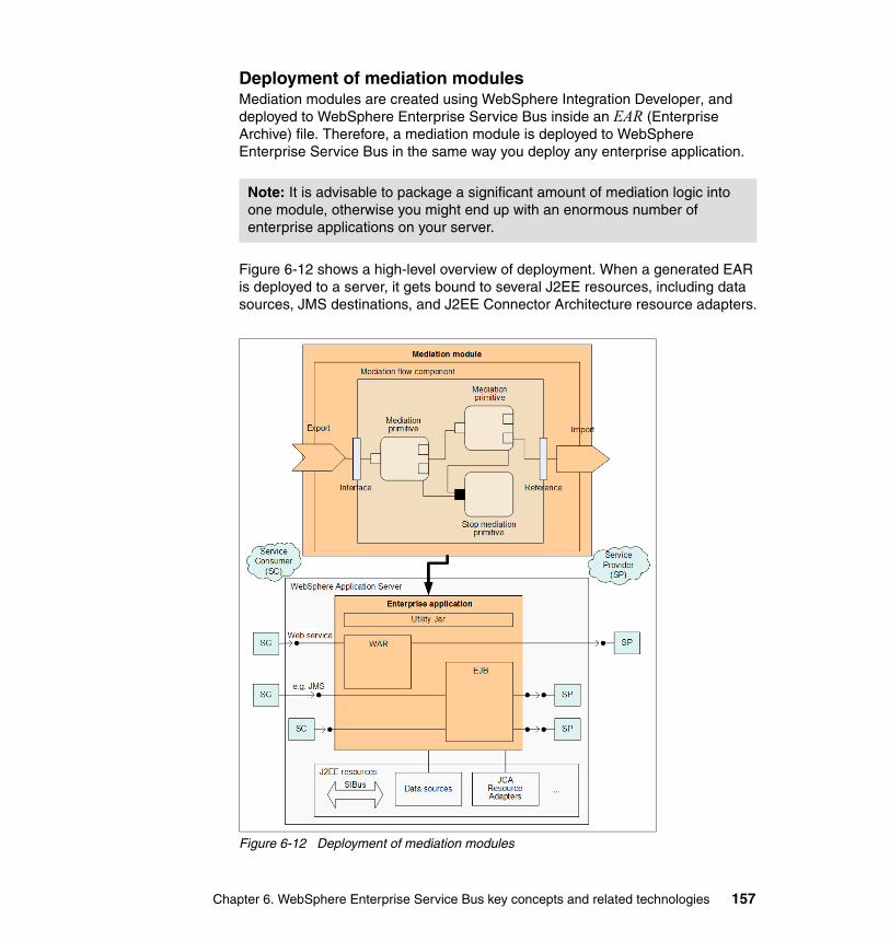
Deployment of mediation modulesMediation modules are created using WebSphere Integration Developer, and deployed to WebSphere Enterprise Service Bus inside an EAR (Enterprise Archive) file. Therefore, a mediation module is deployed to WebSphere Enterprise Service Bus in the same way you deploy any enterprise application.
Figure 6-12 shows a high-level overview of deployment. When a generated EAR is deployed to a server, it gets bound to several J2EE resources, including data sources, JMS destinations, and J2EE Connector Architecture resource adapters.
Figure 6-12 Deployment of mediation modules
Note: It is advisable to package a significant amount of mediation logic into one module, otherwise you might end up with an enormous number of enterprise applications on your server.
Chapter 6. WebSphere Enterprise Service Bus key concepts and related technologies 157

158 Getting Started with WebSphere Enterprise Service Bus V6

Chapter 7. WebSphere Integration Developer key concepts and common tasks
WebSphere Integration Developer is the development environment for building integrated business applications that are targeted for WebSphere Enterprise Service Bus and WebSphere Process Server. One of the primary purposes of WebSphere Integration Developer is to provide the appropriate tools to build and test SCA based applications easily.
This chapter discusses WebSphere Integration Developer key concepts and common tasks in terms of mediation module development for deployment to WebSphere Enterprise Service Bus.
Figure 7-1 presents an overview of the common tasks. It shows the main stages in the mediation module development process and provides assistance in navigating this chapter.
Figure 7-1 Common tasks
7
© Copyright IBM Corp. 2006. All rights reserved. 159
7.1 Key terms and conceptsWebSphere Integration Developer is built on the Rational Software Development Platform, which is based on Eclipse 3.0 technology.
Each IBM product that is built on Rational Software Development Platform coexists and shares plug-ins and features with other products that are based upon Rational Software Development Platform. Rational Software Development Platform is installed once per system with the first product that is installed. As other products that are built on this platform are installed on the system, only the necessary plug-ins are installed.
This section introduces some of the basic terms and concepts that are used in WebSphere Integration Developer. Many of these terms and concepts are common to all Rational Software Development Platform products.
7.1.1 User rolesTwo user roles are associated with WebSphere Integration Developer:
� Integration developer� Application developer
The integration developer is the primary role. It focuses on building service-oriented solutions. This user role expects the tooling to simplify and abstract advanced IT implementation details. The integration developer is familiar with basic programming constructs such as loops, conditions, and string manipulation.
The application developer is knowledgeable in development platforms such as J2EE, understands service-oriented architecture (SOA), Web services, and Java. Application developers implement application specific business logic and expose it as a service.
This chapter focuses on tools that the integration developer uses.
Note: For more information about Eclipse and tutorials, visit the following Web site and explore the Getting Started pages:
http://www.eclipse.org
160 Getting Started with WebSphere Enterprise Service Bus V6
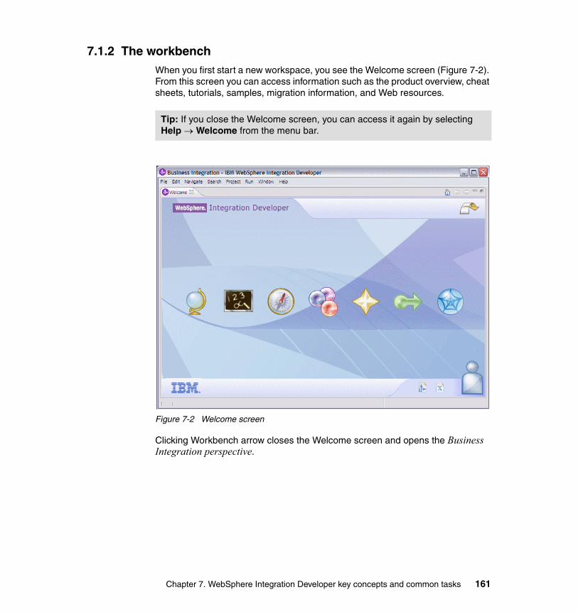
7.1.2 The workbenchWhen you first start a new workspace, you see the Welcome screen (Figure 7-2). From this screen you can access information such as the product overview, cheat sheets, tutorials, samples, migration information, and Web resources.
Figure 7-2 Welcome screen
Clicking Workbench arrow closes the Welcome screen and opens the Business Integration perspective.
Tip: If you close the Welcome screen, you can access it again by selecting Help → Welcome from the menu bar.
Chapter 7. WebSphere Integration Developer key concepts and common tasks 161
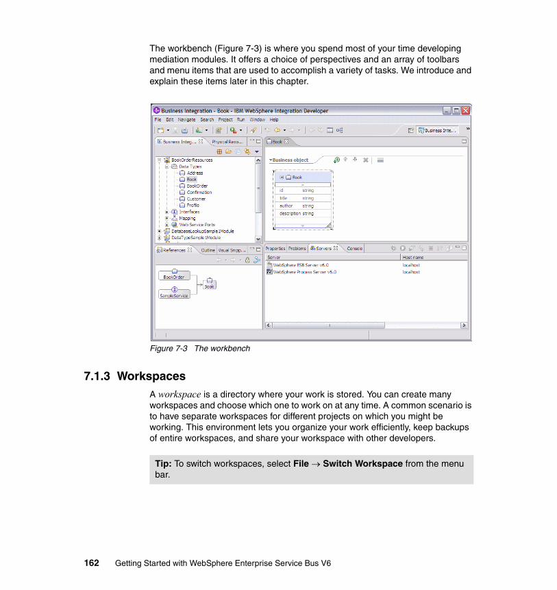
The workbench (Figure 7-3) is where you spend most of your time developing mediation modules. It offers a choice of perspectives and an array of toolbars and menu items that are used to accomplish a variety of tasks. We introduce and explain these items later in this chapter.
Figure 7-3 The workbench
7.1.3 WorkspacesA workspace is a directory where your work is stored. You can create many workspaces and choose which one to work on at any time. A common scenario is to have separate workspaces for different projects on which you might be working. This environment lets you organize your work efficiently, keep backups of entire workspaces, and share your workspace with other developers.
Tip: To switch workspaces, select File → Switch Workspace from the menu bar.
162 Getting Started with WebSphere Enterprise Service Bus V6
7.1.4 Project typesThere are two important project types when working with WebSphere Integration Developer:
� Module project
A module project represents a single deployable unit and encapsulates SCA components, J2EE projects, Java projects and required libraries. When deploying to WebSphere Enterprise Service Bus your choice of module type is limited to mediation modules.
� Shared library
A shared library is another type of business integration project. Unlike modules, libraries are not deployable units. Shared libraries hold resources that are shared between module projects. At run time, libraries are not shared but are deployed with the module that depends on it.
If you are deploying to WebSphere Enterprise Service Bus, you can only create two types of artifacts in a shared library: business objects and interfaces. The Mapping folder only applies to WebSphere Process Server projects.
Additionally, you can use shared libraries to hold WSDL bindings in a Web Service Bindings folder which is created when you copy WSDL files into your library.
7.1.5 PerspectivesA perspective is a role-based collection of views and editors. Perspectives are very useful because they offer users the tools that are most needed to perform their current job. Perspectives are fully customizable. Views and editors can be added, removed, and rearranged.
The primary WebSphere Integration Developer perspective is the Business Integration perspective. We use this perspective almost exclusively because it contains all the tools that we need to create, to develop, and to manage business integration projects. Figure 7-3 on page 162 shows the Business Integration perspective on the workbench.
Tip: Libraries can be added to the dependency list for a module from the Module Dependency editor. To open this editor, right-click the module folder and select Open Dependency Editor.
Tip: To restore any perspective to its default layout, select Window → Reset Perspective from the menu bar.
Chapter 7. WebSphere Integration Developer key concepts and common tasks 163
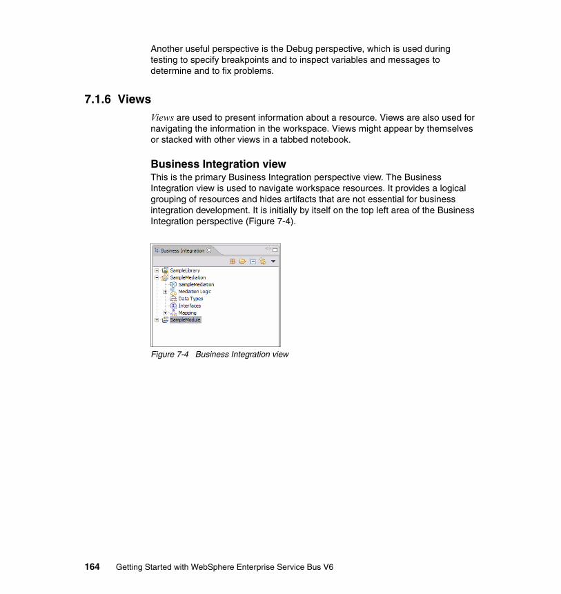
Another useful perspective is the Debug perspective, which is used during testing to specify breakpoints and to inspect variables and messages to determine and to fix problems.
7.1.6 ViewsViews are used to present information about a resource. Views are also used for navigating the information in the workspace. Views might appear by themselves or stacked with other views in a tabbed notebook.
Business Integration viewThis is the primary Business Integration perspective view. The Business Integration view is used to navigate workspace resources. It provides a logical grouping of resources and hides artifacts that are not essential for business integration development. It is initially by itself on the top left area of the Business Integration perspective (Figure 7-4).
Figure 7-4 Business Integration view
164 Getting Started with WebSphere Enterprise Service Bus V6
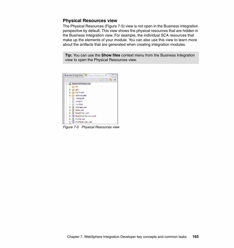
Physical Resources viewThe Physical Resources (Figure 7-5) view is not open in the Business Integration perspective by default. This view shows the physical resources that are hidden in the Business Integration view. For example, the individual SCA resources that make up the elements of your module. You can also use this view to learn more about the artifacts that are generated when creating integration modules.
Figure 7-5 Physical Resources view
Tip: You can use the Show files context menu from the Business Integration view to open the Physical Resources view.
Chapter 7. WebSphere Integration Developer key concepts and common tasks 165
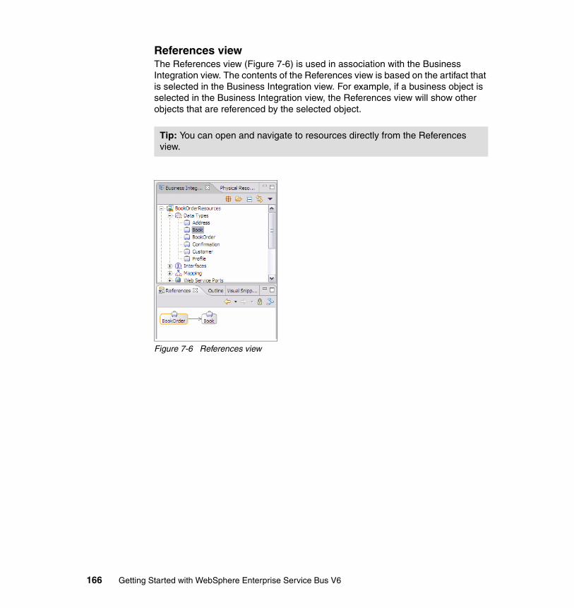
References viewThe References view (Figure 7-6) is used in association with the Business Integration view. The contents of the References view is based on the artifact that is selected in the Business Integration view. For example, if a business object is selected in the Business Integration view, the References view will show other objects that are referenced by the selected object.
Figure 7-6 References view
Tip: You can open and navigate to resources directly from the References view.
166 Getting Started with WebSphere Enterprise Service Bus V6
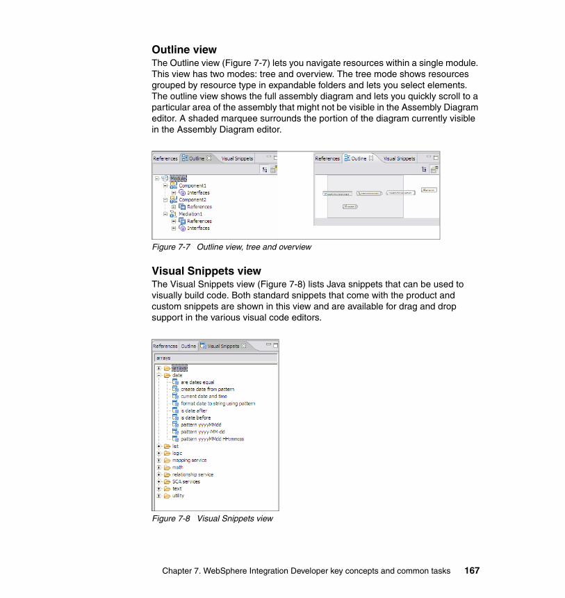
Outline viewThe Outline view (Figure 7-7) lets you navigate resources within a single module. This view has two modes: tree and overview. The tree mode shows resources grouped by resource type in expandable folders and lets you select elements. The outline view shows the full assembly diagram and lets you quickly scroll to a particular area of the assembly that might not be visible in the Assembly Diagram editor. A shaded marquee surrounds the portion of the diagram currently visible in the Assembly Diagram editor.
Figure 7-7 Outline view, tree and overview
Visual Snippets viewThe Visual Snippets view (Figure 7-8) lists Java snippets that can be used to visually build code. Both standard snippets that come with the product and custom snippets are shown in this view and are available for drag and drop support in the various visual code editors.
Figure 7-8 Visual Snippets view
Chapter 7. WebSphere Integration Developer key concepts and common tasks 167
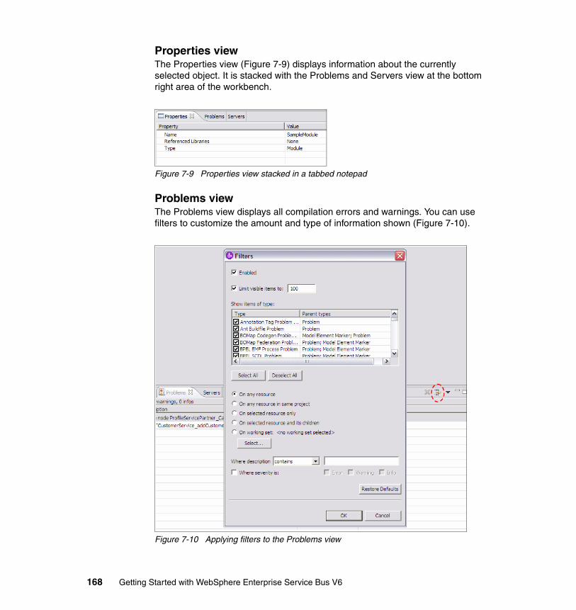
Properties viewThe Properties view (Figure 7-9) displays information about the currently selected object. It is stacked with the Problems and Servers view at the bottom right area of the workbench.
Figure 7-9 Properties view stacked in a tabbed notepad
Problems viewThe Problems view displays all compilation errors and warnings. You can use filters to customize the amount and type of information shown (Figure 7-10).
Figure 7-10 Applying filters to the Problems view
168 Getting Started with WebSphere Enterprise Service Bus V6
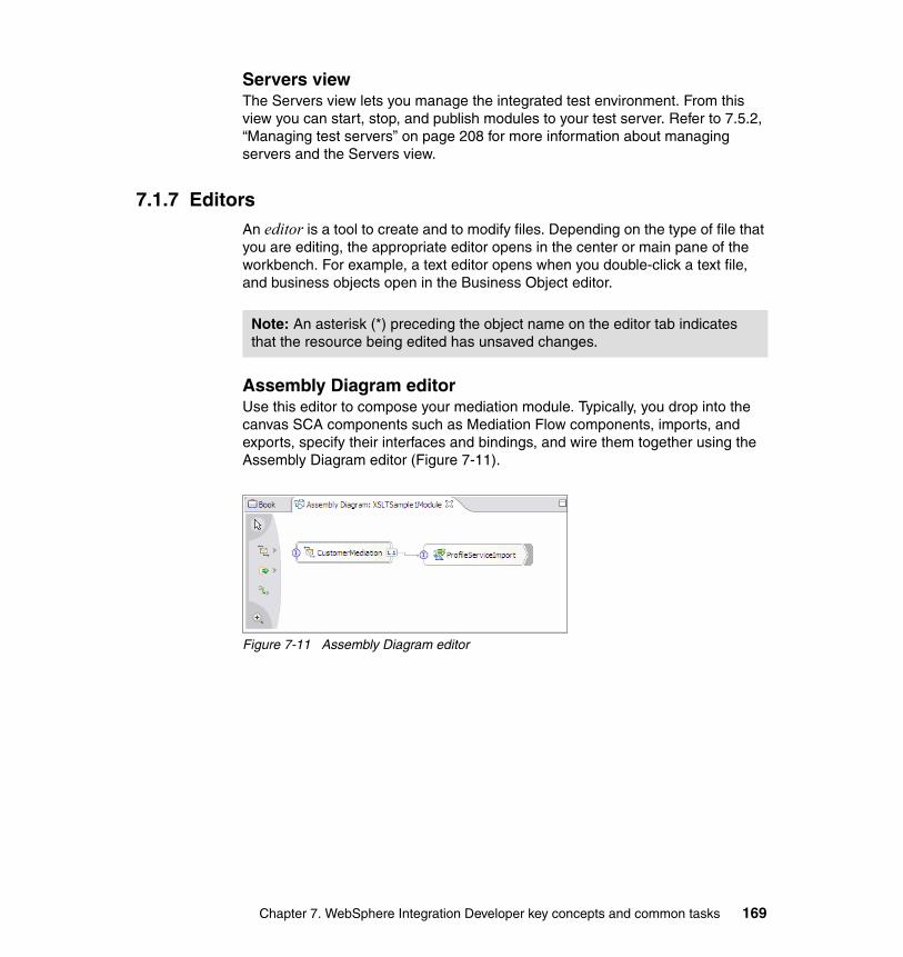
Servers viewThe Servers view lets you manage the integrated test environment. From this view you can start, stop, and publish modules to your test server. Refer to 7.5.2, “Managing test servers” on page 208 for more information about managing servers and the Servers view.
7.1.7 EditorsAn editor is a tool to create and to modify files. Depending on the type of file that you are editing, the appropriate editor opens in the center or main pane of the workbench. For example, a text editor opens when you double-click a text file, and business objects open in the Business Object editor.
Assembly Diagram editorUse this editor to compose your mediation module. Typically, you drop into the canvas SCA components such as Mediation Flow components, imports, and exports, specify their interfaces and bindings, and wire them together using the Assembly Diagram editor (Figure 7-11).
Figure 7-11 Assembly Diagram editor
Note: An asterisk (*) preceding the object name on the editor tab indicates that the resource being edited has unsaved changes.
Chapter 7. WebSphere Integration Developer key concepts and common tasks 169
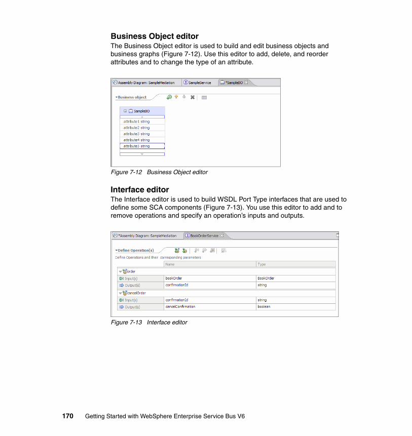
Business Object editorThe Business Object editor is used to build and edit business objects and business graphs (Figure 7-12). Use this editor to add, delete, and reorder attributes and to change the type of an attribute.
Figure 7-12 Business Object editor
Interface editorThe Interface editor is used to build WSDL Port Type interfaces that are used to define some SCA components (Figure 7-13). You use this editor to add and to remove operations and specify an operation’s inputs and outputs.
Figure 7-13 Interface editor
170 Getting Started with WebSphere Enterprise Service Bus V6
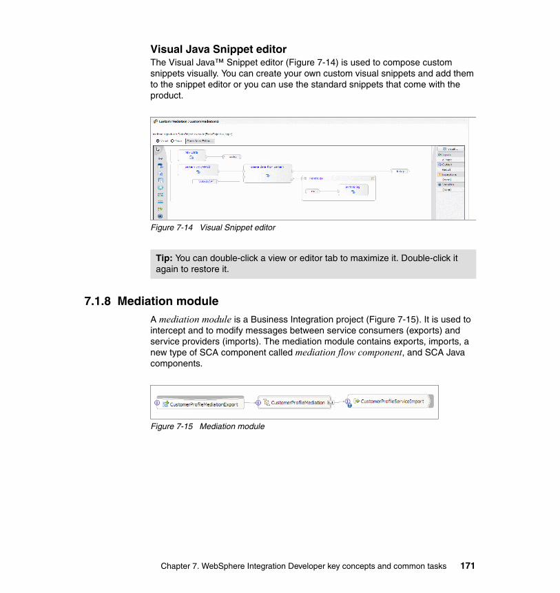
Visual Java Snippet editorThe Visual Java™ Snippet editor (Figure 7-14) is used to compose custom snippets visually. You can create your own custom visual snippets and add them to the snippet editor or you can use the standard snippets that come with the product.
Figure 7-14 Visual Snippet editor
7.1.8 Mediation moduleA mediation module is a Business Integration project (Figure 7-15). It is used to intercept and to modify messages between service consumers (exports) and service providers (imports). The mediation module contains exports, imports, a new type of SCA component called mediation flow component, and SCA Java components.
Figure 7-15 Mediation module
Tip: You can double-click a view or editor tab to maximize it. Double-click it again to restore it.
Chapter 7. WebSphere Integration Developer key concepts and common tasks 171
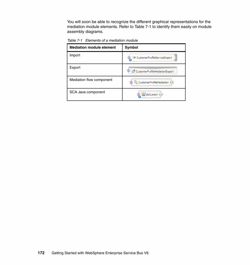
You will soon be able to recognize the different graphical representations for the mediation module elements. Refer to Table 7-1 to identify them easily on module assembly diagrams.
Table 7-1 Elements of a mediation module
Mediation module element Symbol
Import
Export
Mediation flow component
SCA Java component
172 Getting Started with WebSphere Enterprise Service Bus V6
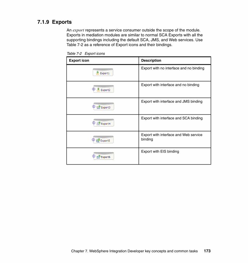
7.1.9 ExportsAn export represents a service consumer outside the scope of the module. Exports in mediation modules are similar to normal SCA Exports with all the supporting bindings including the default SCA, JMS, and Web services. Use Table 7-2 as a reference of Export icons and their bindings.
Table 7-2 Export icons
Export icon Description
Export with no interface and no binding
Export with interface and no binding
Export with interface and JMS binding
Export with interface and SCA binding
Export with interface and Web service binding
Export with EIS binding
Chapter 7. WebSphere Integration Developer key concepts and common tasks 173
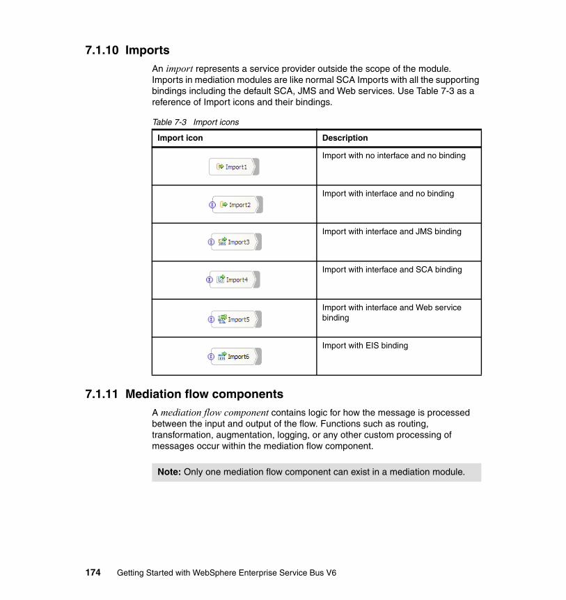
7.1.10 ImportsAn import represents a service provider outside the scope of the module. Imports in mediation modules are like normal SCA Imports with all the supporting bindings including the default SCA, JMS and Web services. Use Table 7-3 as a reference of Import icons and their bindings.
Table 7-3 Import icons
7.1.11 Mediation flow componentsA mediation flow component contains logic for how the message is processed between the input and output of the flow. Functions such as routing, transformation, augmentation, logging, or any other custom processing of messages occur within the mediation flow component.
Import icon Description
Import with no interface and no binding
Import with interface and no binding
Import with interface and JMS binding
Import with interface and SCA binding
Import with interface and Web service binding
Import with EIS binding
Note: Only one mediation flow component can exist in a mediation module.
174 Getting Started with WebSphere Enterprise Service Bus V6
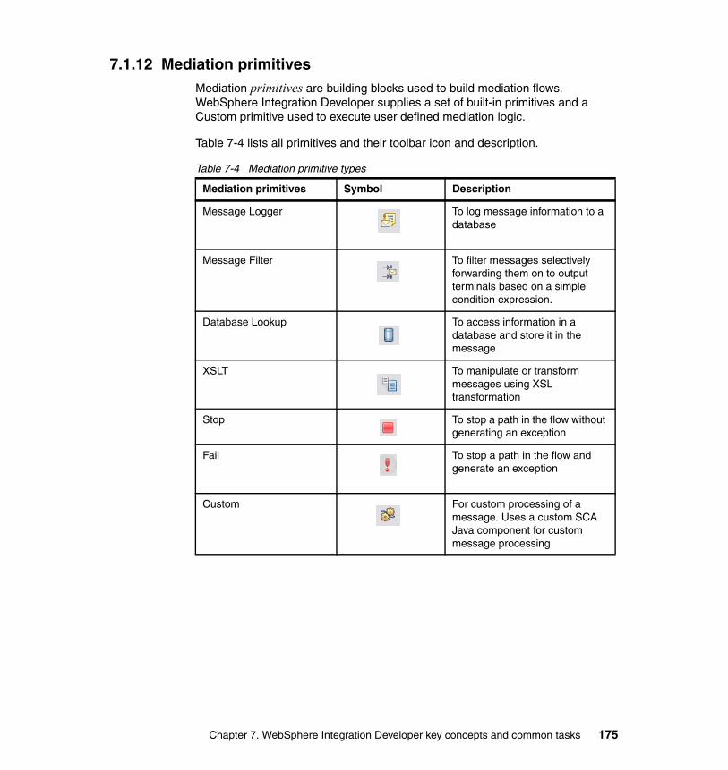
7.1.12 Mediation primitivesMediation primitives are building blocks used to build mediation flows. WebSphere Integration Developer supplies a set of built-in primitives and a Custom primitive used to execute user defined mediation logic.
Table 7-4 lists all primitives and their toolbar icon and description.
Table 7-4 Mediation primitive types
Mediation primitives Symbol Description
Message Logger To log message information to a database
Message Filter To filter messages selectively forwarding them on to output terminals based on a simple condition expression.
Database Lookup To access information in a database and store it in the message
XSLT To manipulate or transform messages using XSL transformation
Stop To stop a path in the flow without generating an exception
Fail To stop a path in the flow and generate an exception
Custom For custom processing of a message. Uses a custom SCA Java component for custom message processing
Chapter 7. WebSphere Integration Developer key concepts and common tasks 175
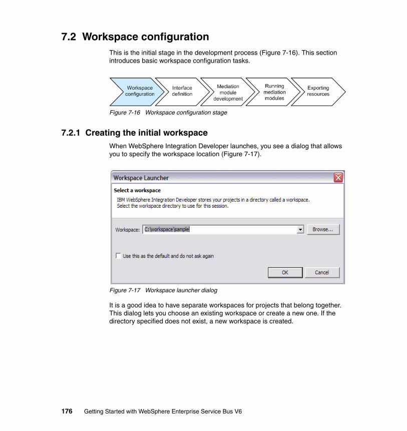
7.2 Workspace configurationThis is the initial stage in the development process (Figure 7-16). This section introduces basic workspace configuration tasks.
Figure 7-16 Workspace configuration stage
7.2.1 Creating the initial workspaceWhen WebSphere Integration Developer launches, you see a dialog that allows you to specify the workspace location (Figure 7-17).
Figure 7-17 Workspace launcher dialog
It is a good idea to have separate workspaces for projects that belong together. This dialog lets you choose an existing workspace or create a new one. If the directory specified does not exist, a new workspace is created.
176 Getting Started with WebSphere Enterprise Service Bus V6
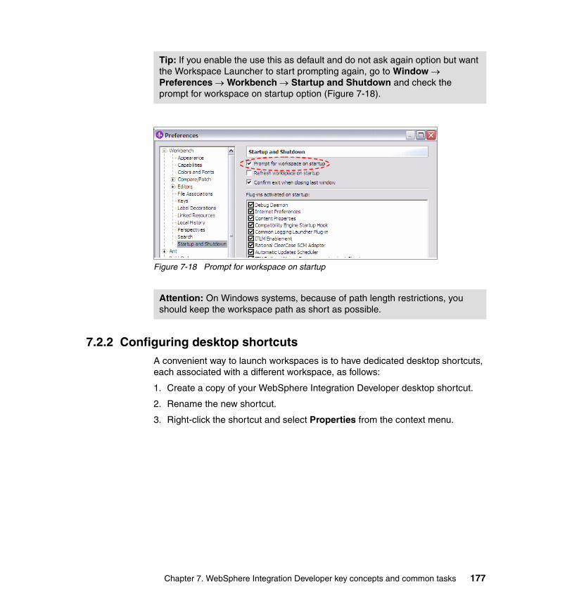
Figure 7-18 Prompt for workspace on startup
7.2.2 Configuring desktop shortcutsA convenient way to launch workspaces is to have dedicated desktop shortcuts, each associated with a different workspace, as follows:
1. Create a copy of your WebSphere Integration Developer desktop shortcut.
2. Rename the new shortcut.
3. Right-click the shortcut and select Properties from the context menu.
Tip: If you enable the use this as default and do not ask again option but want the Workspace Launcher to start prompting again, go to Window → Preferences → Workbench → Startup and Shutdown and check the prompt for workspace on startup option (Figure 7-18).
Attention: On Windows systems, because of path length restrictions, you should keep the workspace path as short as possible.
Chapter 7. WebSphere Integration Developer key concepts and common tasks 177
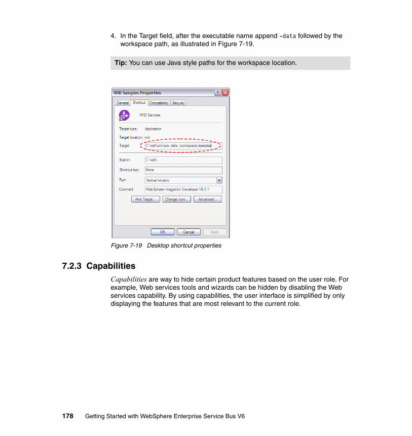
4. In the Target field, after the executable name append -data followed by the workspace path, as illustrated in Figure 7-19.
Figure 7-19 Desktop shortcut properties
7.2.3 CapabilitiesCapabilities are way to hide certain product features based on the user role. For example, Web services tools and wizards can be hidden by disabling the Web services capability. By using capabilities, the user interface is simplified by only displaying the features that are most relevant to the current role.
Tip: You can use Java style paths for the workspace location.
178 Getting Started with WebSphere Enterprise Service Bus V6

Capabilities that are not enabled can be enabled the first time the feature is accessed. Capabilities can also be enabled from the menu bar by selecting Window → Preferences, by expanding Workbench, and by selecting Capabilities (Figure 7-20).
Figure 7-20 Capabilities
Note: Capabilities are associated with a given workspace. It is important to be aware that it might be necessary for you to turn on certain capabilities in order to make sure that the features that you typically use during your developing activities are visible to you.
Chapter 7. WebSphere Integration Developer key concepts and common tasks 179
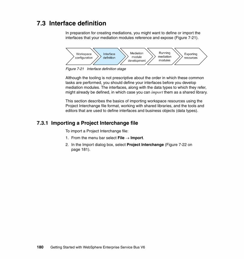
7.3 Interface definitionIn preparation for creating mediations, you might want to define or import the interfaces that your mediation modules reference and expose (Figure 7-21).
Figure 7-21 Interface definition stage
Although the tooling is not prescriptive about the order in which these common tasks are performed, you should define your interfaces before you develop mediation modules. The interfaces, along with the data types to which they refer, might already be defined, in which case you can import them as a shared library.
This section describes the basics of importing workspace resources using the Project Interchange file format, working with shared libraries, and the tools and editors that are used to define interfaces and business objects (data types).
7.3.1 Importing a Project Interchange fileTo import a Project Interchange file:
1. From the menu bar select File → Import.
2. In the Import dialog box, select Project Interchange (Figure 7-22 on page 181).
180 Getting Started with WebSphere Enterprise Service Bus V6
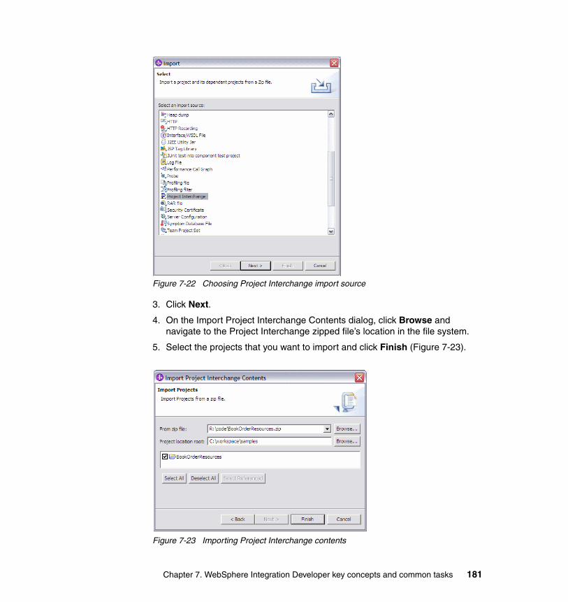
Figure 7-22 Choosing Project Interchange import source
3. Click Next.
4. On the Import Project Interchange Contents dialog, click Browse and navigate to the Project Interchange zipped file’s location in the file system.
5. Select the projects that you want to import and click Finish (Figure 7-23).
Figure 7-23 Importing Project Interchange contents
Chapter 7. WebSphere Integration Developer key concepts and common tasks 181

7.3.2 Working with shared librariesA shared library is a special type of Business Integration project that holds resources shared between modules.
Creating a new libraryTo create a new shared library:
1. Right-click the Business Integration view and select New → Library from the context menu.
2. Name the library and click Finish.
Adding libraries to a mediation module dependency listTo add a dependent library to a module:
1. Double-click the modules’ top level project folder to open the Module Dependency editor.
2. Click Add in the libraries section and select the library to add (Figure 7-24 on page 183).
3. Click OK.
Note: Only business objects and interfaces can exist in a WebSphere Enterprise Service Bus shared library. The mapping folder only applies to WebSphere Process Server projects. An additional Web Service Bindings folder is created automatically if you store WSDL files in a library.
182 Getting Started with WebSphere Enterprise Service Bus V6
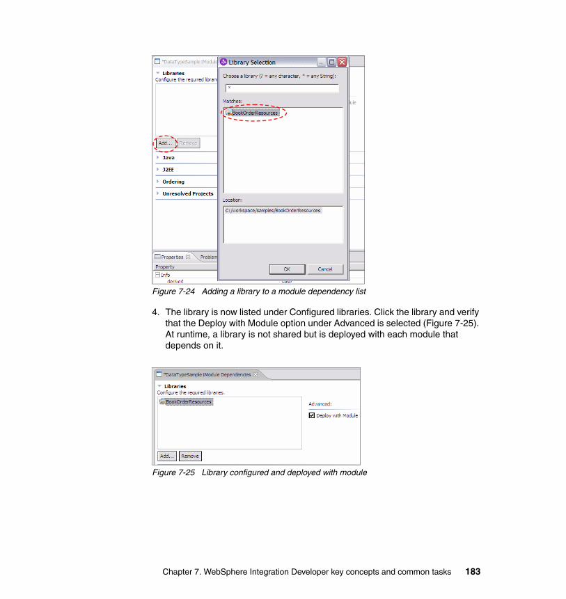
Figure 7-24 Adding a library to a module dependency list
4. The library is now listed under Configured libraries. Click the library and verify that the Deploy with Module option under Advanced is selected (Figure 7-25). At runtime, a library is not shared but is deployed with each module that depends on it.
Figure 7-25 Library configured and deployed with module
Chapter 7. WebSphere Integration Developer key concepts and common tasks 183
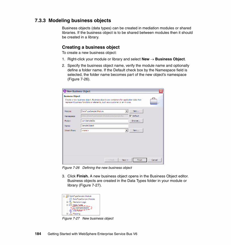
7.3.3 Modeling business objectsBusiness objects (data types) can be created in mediation modules or shared libraries. If the business object is to be shared between modules then it should be created in a library.
Creating a business objectTo create a new business object:
1. Right-click your module or library and select New → Business Object.
2. Specify the business object name, verify the module name and optionally define a folder name. If the Default check box by the Namespace field is selected, the folder name becomes part of the new object’s namespace (Figure 7-26).
Figure 7-26 Defining the new business object
3. Click Finish. A new business object opens in the Business Object editor. Business objects are created in the Data Types folder in your module or library (Figure 7-27).
Figure 7-27 New business object
184 Getting Started with WebSphere Enterprise Service Bus V6
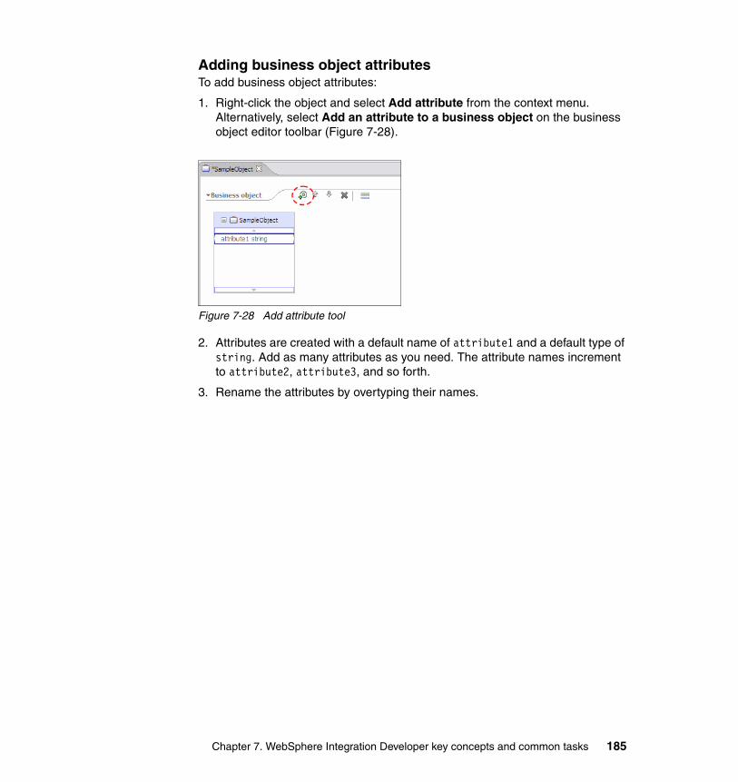
Adding business object attributesTo add business object attributes:
1. Right-click the object and select Add attribute from the context menu. Alternatively, select Add an attribute to a business object on the business object editor toolbar (Figure 7-28).
Figure 7-28 Add attribute tool
2. Attributes are created with a default name of attribute1 and a default type of string. Add as many attributes as you need. The attribute names increment to attribute2, attribute3, and so forth.
3. Rename the attributes by overtyping their names.
Chapter 7. WebSphere Integration Developer key concepts and common tasks 185
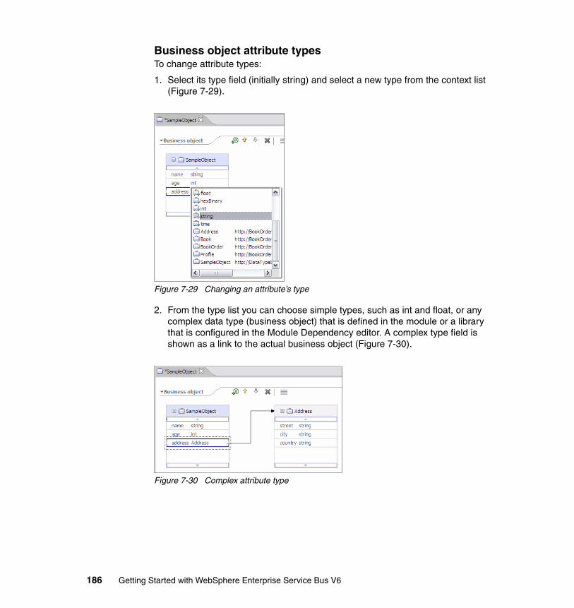
Business object attribute typesTo change attribute types:
1. Select its type field (initially string) and select a new type from the context list (Figure 7-29).
Figure 7-29 Changing an attribute’s type
2. From the type list you can choose simple types, such as int and float, or any complex data type (business object) that is defined in the module or a library that is configured in the Module Dependency editor. A complex type field is shown as a link to the actual business object (Figure 7-30).
Figure 7-30 Complex attribute type
186 Getting Started with WebSphere Enterprise Service Bus V6
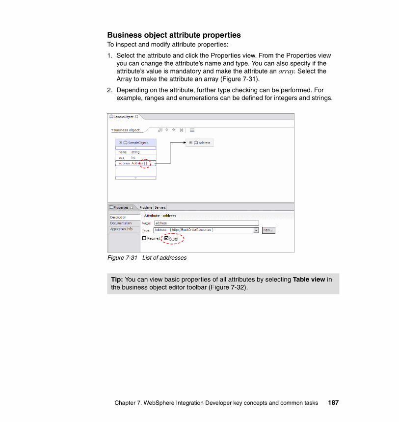
Business object attribute propertiesTo inspect and modify attribute properties:
1. Select the attribute and click the Properties view. From the Properties view you can change the attribute’s name and type. You can also specify if the attribute’s value is mandatory and make the attribute an array. Select the Array to make the attribute an array (Figure 7-31).
2. Depending on the attribute, further type checking can be performed. For example, ranges and enumerations can be defined for integers and strings.
Figure 7-31 List of addresses
Tip: You can view basic properties of all attributes by selecting Table view in the business object editor toolbar (Figure 7-32).
Chapter 7. WebSphere Integration Developer key concepts and common tasks 187
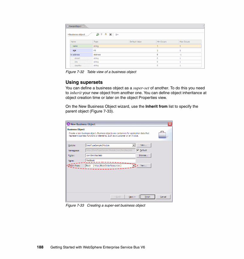
Figure 7-32 Table view of a business object
Using supersetsYou can define a business object as a super-set of another. To do this you need to inherit your new object from another one. You can define object inheritance at object creation time or later on the object Properties view.
On the New Business Object wizard, use the Inherit from list to specify the parent object (Figure 7-33).
Figure 7-33 Creating a super-set business object
188 Getting Started with WebSphere Enterprise Service Bus V6
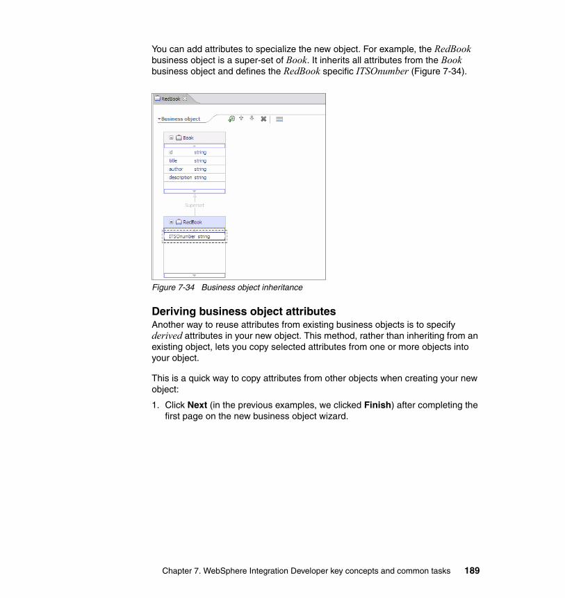
You can add attributes to specialize the new object. For example, the RedBook business object is a super-set of Book. It inherits all attributes from the Book business object and defines the RedBook specific ITSOnumber (Figure 7-34).
Figure 7-34 Business object inheritance
Deriving business object attributesAnother way to reuse attributes from existing business objects is to specify derived attributes in your new object. This method, rather than inheriting from an existing object, lets you copy selected attributes from one or more objects into your object.
This is a quick way to copy attributes from other objects when creating your new object:
1. Click Next (in the previous examples, we clicked Finish) after completing the first page on the new business object wizard.
Chapter 7. WebSphere Integration Developer key concepts and common tasks 189
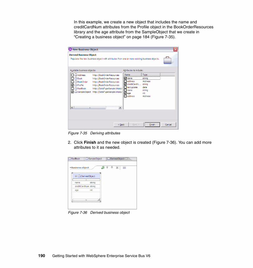
In this example, we create a new object that includes the name and creditCardNum attributes from the Profile object in the BookOrderResources library and the age attribute from the SampleObject that we create in “Creating a business object” on page 184 (Figure 7-35).
Figure 7-35 Deriving attributes
2. Click Finish and the new object is created (Figure 7-36). You can add more attributes to it as needed.
Figure 7-36 Derived business object
190 Getting Started with WebSphere Enterprise Service Bus V6
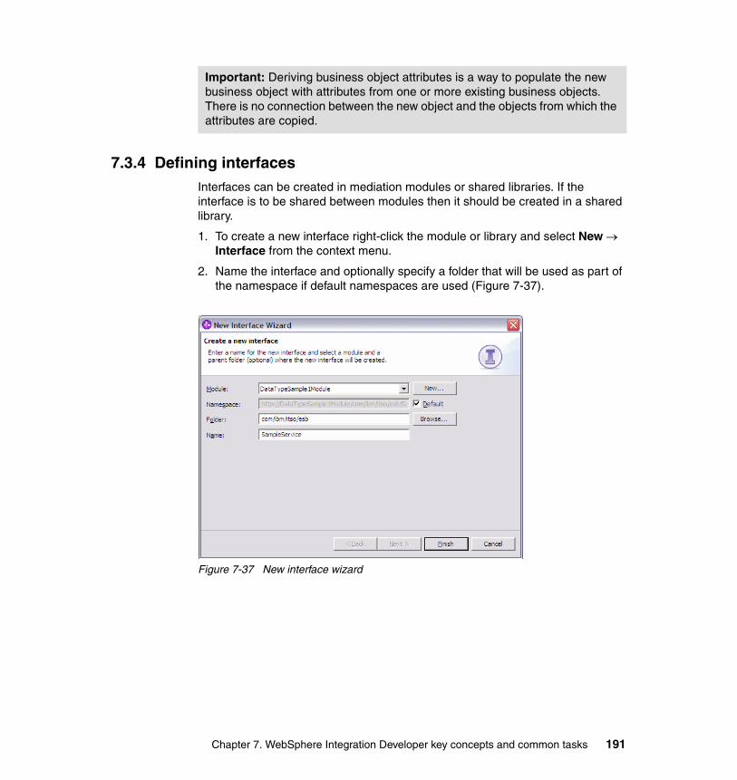
7.3.4 Defining interfacesInterfaces can be created in mediation modules or shared libraries. If the interface is to be shared between modules then it should be created in a shared library.
1. To create a new interface right-click the module or library and select New → Interface from the context menu.
2. Name the interface and optionally specify a folder that will be used as part of the namespace if default namespaces are used (Figure 7-37).
Figure 7-37 New interface wizard
Important: Deriving business object attributes is a way to populate the new business object with attributes from one or more existing business objects. There is no connection between the new object and the objects from which the attributes are copied.
Chapter 7. WebSphere Integration Developer key concepts and common tasks 191
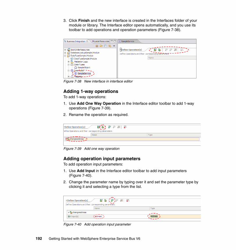
3. Click Finish and the new interface is created in the Interfaces folder of your module or library. The Interface editor opens automatically, and you use its toolbar to add operations and operation parameters (Figure 7-38).
Figure 7-38 New interface in interface editor
Adding 1-way operationsTo add 1-way operations:
1. Use Add One Way Operation in the Interface editor toolbar to add 1-way operations (Figure 7-39).
2. Rename the operation as required.
Figure 7-39 Add one way operation
Adding operation input parametersTo add operation input parameters:
1. Use Add Input in the Interface editor toolbar to add input parameters (Figure 7-40).
2. Change the parameter name by typing over it and set the parameter type by clicking it and selecting a type from the list.
Figure 7-40 Add operation input parameter
192 Getting Started with WebSphere Enterprise Service Bus V6
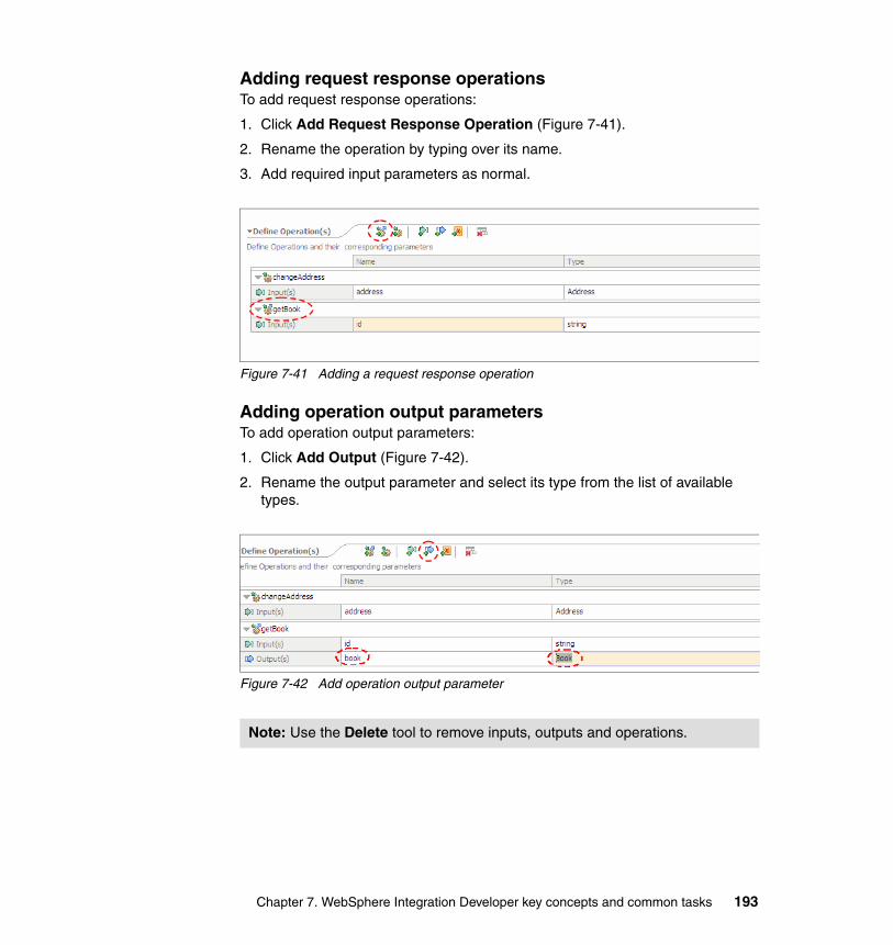
Adding request response operationsTo add request response operations:
1. Click Add Request Response Operation (Figure 7-41).
2. Rename the operation by typing over its name.
3. Add required input parameters as normal.
Figure 7-41 Adding a request response operation
Adding operation output parametersTo add operation output parameters:
1. Click Add Output (Figure 7-42).
2. Rename the output parameter and select its type from the list of available types.
Figure 7-42 Add operation output parameter
Note: Use the Delete tool to remove inputs, outputs and operations.
Chapter 7. WebSphere Integration Developer key concepts and common tasks 193
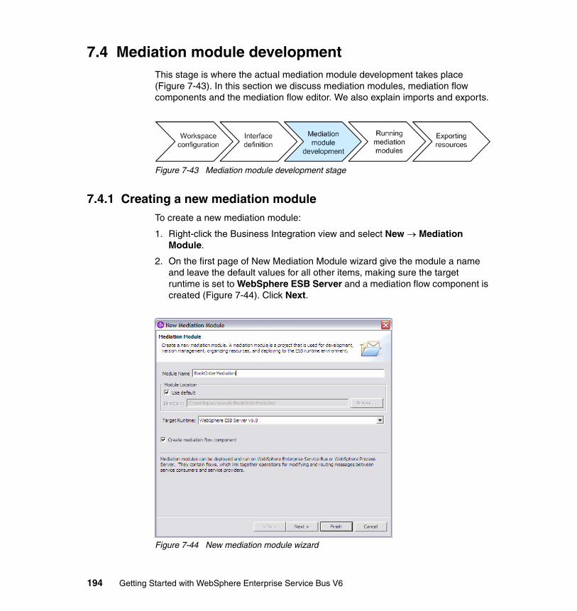
7.4 Mediation module developmentThis stage is where the actual mediation module development takes place (Figure 7-43). In this section we discuss mediation modules, mediation flow components and the mediation flow editor. We also explain imports and exports.
Figure 7-43 Mediation module development stage
7.4.1 Creating a new mediation moduleTo create a new mediation module:
1. Right-click the Business Integration view and select New → Mediation Module.
2. On the first page of New Mediation Module wizard give the module a name and leave the default values for all other items, making sure the target runtime is set to WebSphere ESB Server and a mediation flow component is created (Figure 7-44). Click Next.
Figure 7-44 New mediation module wizard
194 Getting Started with WebSphere Enterprise Service Bus V6
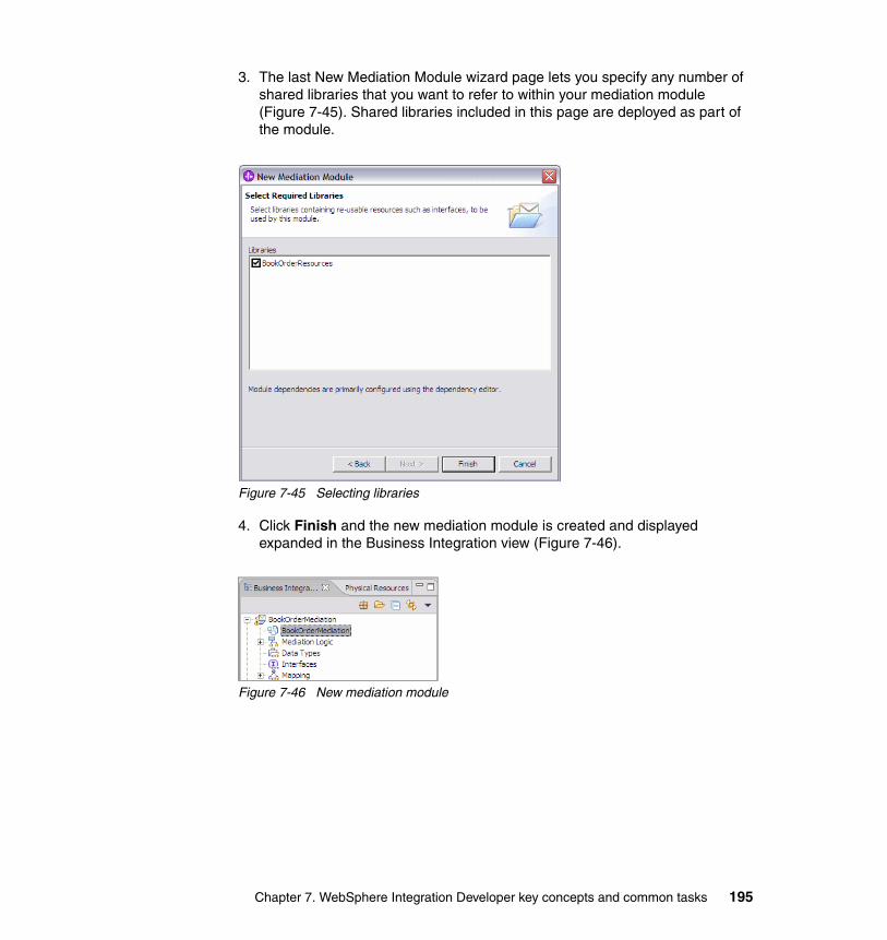
3. The last New Mediation Module wizard page lets you specify any number of shared libraries that you want to refer to within your mediation module (Figure 7-45). Shared libraries included in this page are deployed as part of the module.
Figure 7-45 Selecting libraries
4. Click Finish and the new mediation module is created and displayed expanded in the Business Integration view (Figure 7-46).
Figure 7-46 New mediation module
Chapter 7. WebSphere Integration Developer key concepts and common tasks 195
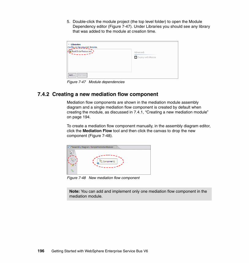
5. Double-click the module project (the top level folder) to open the Module Dependency editor (Figure 7-47). Under Libraries you should see any library that was added to the module at creation time.
Figure 7-47 Module dependencies
7.4.2 Creating a new mediation flow componentMediation flow components are shown in the mediation module assembly diagram and a single mediation flow component is created by default when creating the module, as discussed in 7.4.1, “Creating a new mediation module” on page 194.
To create a mediation flow component manually, in the assembly diagram editor, click the Mediation Flow tool and then click the canvas to drop the new component (Figure 7-48).
Figure 7-48 New mediation flow component
Note: You can add and implement only one mediation flow component in the mediation module.
196 Getting Started with WebSphere Enterprise Service Bus V6
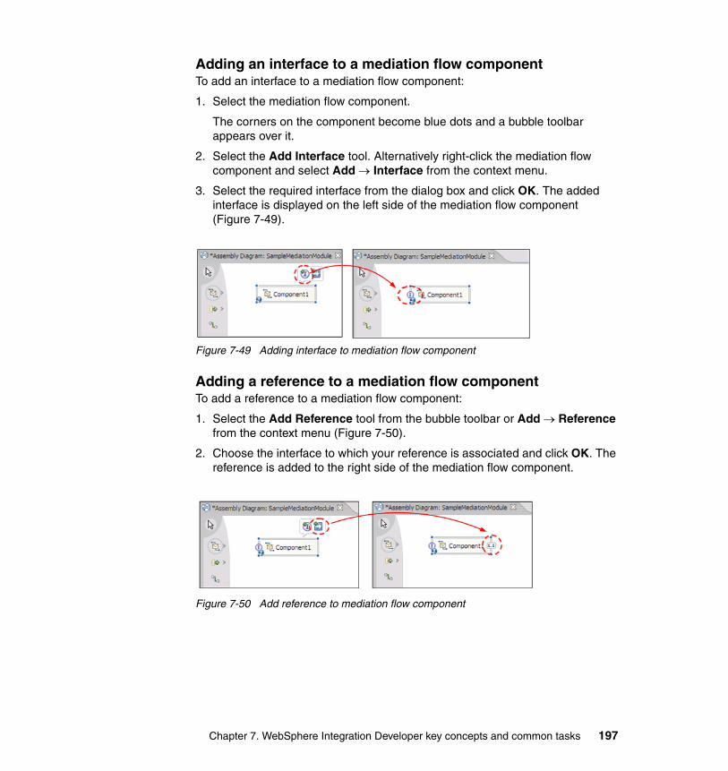
Adding an interface to a mediation flow componentTo add an interface to a mediation flow component:
1. Select the mediation flow component.
The corners on the component become blue dots and a bubble toolbar appears over it.
2. Select the Add Interface tool. Alternatively right-click the mediation flow component and select Add → Interface from the context menu.
3. Select the required interface from the dialog box and click OK. The added interface is displayed on the left side of the mediation flow component (Figure 7-49).
Figure 7-49 Adding interface to mediation flow component
Adding a reference to a mediation flow componentTo add a reference to a mediation flow component:
1. Select the Add Reference tool from the bubble toolbar or Add → Reference from the context menu (Figure 7-50).
2. Choose the interface to which your reference is associated and click OK. The reference is added to the right side of the mediation flow component.
Figure 7-50 Add reference to mediation flow component
Chapter 7. WebSphere Integration Developer key concepts and common tasks 197
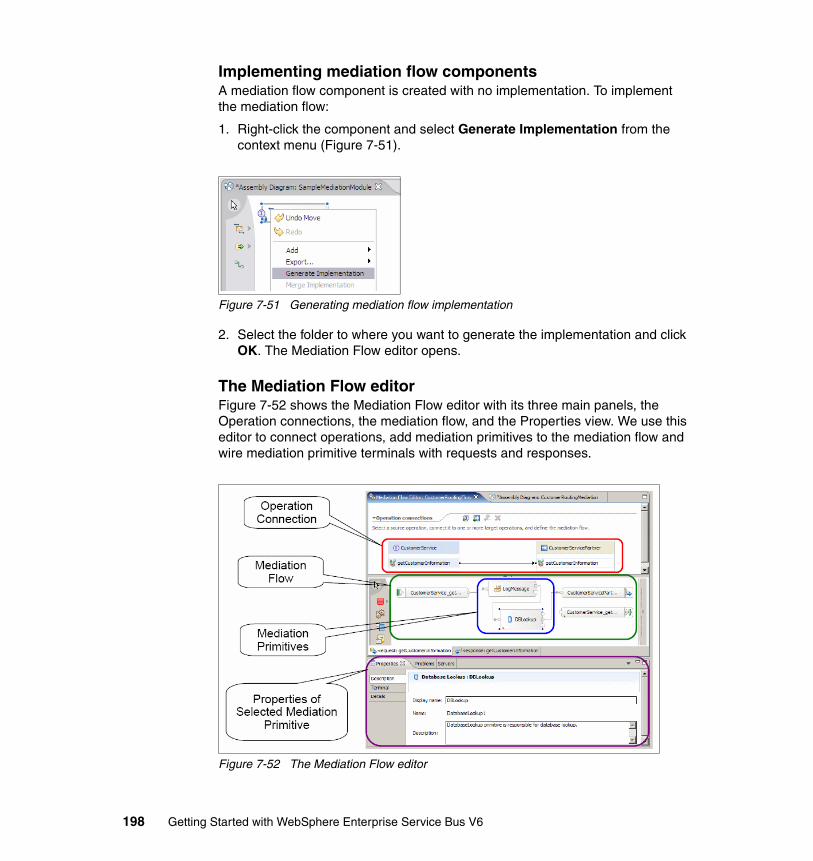
Implementing mediation flow componentsA mediation flow component is created with no implementation. To implement the mediation flow:
1. Right-click the component and select Generate Implementation from the context menu (Figure 7-51).
Figure 7-51 Generating mediation flow implementation
2. Select the folder to where you want to generate the implementation and click OK. The Mediation Flow editor opens.
The Mediation Flow editorFigure 7-52 shows the Mediation Flow editor with its three main panels, the Operation connections, the mediation flow, and the Properties view. We use this editor to connect operations, add mediation primitives to the mediation flow and wire mediation primitive terminals with requests and responses.
Figure 7-52 The Mediation Flow editor
198 Getting Started with WebSphere Enterprise Service Bus V6
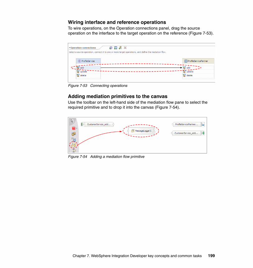
Wiring interface and reference operationsTo wire operations, on the Operation connections panel, drag the source operation on the interface to the target operation on the reference (Figure 7-53).
Figure 7-53 Connecting operations
Adding mediation primitives to the canvasUse the toolbar on the left-hand side of the mediation flow pane to select the required primitive and to drop it into the canvas (Figure 7-54).
Figure 7-54 Adding a mediation flow primitive
Chapter 7. WebSphere Integration Developer key concepts and common tasks 199
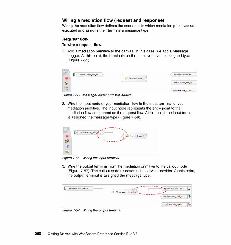
Wiring a mediation flow (request and response)Wiring the mediation flow defines the sequence in which mediation primitives are executed and assigns their terminal’s message type.
Request flowTo wire a request flow:
1. Add a mediation primitive to the canvas. In this case, we add a Message Logger. At this point, the terminals on the primitive have no assigned type (Figure 7-55).
Figure 7-55 MessageLogger primitive added
2. Wire the input node of your mediation flow to the input terminal of your mediation primitive. The input node represents the entry point to the mediation flow component on the request flow. At this point, the input terminal is assigned the message type (Figure 7-56).
Figure 7-56 Wiring the input terminal
3. Wire the output terminal from the mediation primitive to the callout node (Figure 7-57). The callout node represents the service provider. At this point, the output terminal is assigned the message type.
Figure 7-57 Wiring the output terminal
200 Getting Started with WebSphere Enterprise Service Bus V6
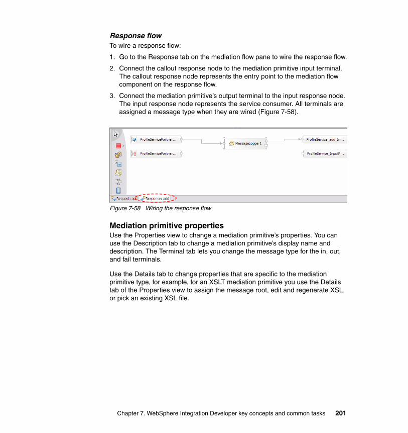
Response flowTo wire a response flow:
1. Go to the Response tab on the mediation flow pane to wire the response flow.
2. Connect the callout response node to the mediation primitive input terminal. The callout response node represents the entry point to the mediation flow component on the response flow.
3. Connect the mediation primitive’s output terminal to the input response node. The input response node represents the service consumer. All terminals are assigned a message type when they are wired (Figure 7-58).
Figure 7-58 Wiring the response flow
Mediation primitive propertiesUse the Properties view to change a mediation primitive’s properties. You can use the Description tab to change a mediation primitive’s display name and description. The Terminal tab lets you change the message type for the in, out, and fail terminals.
Use the Details tab to change properties that are specific to the mediation primitive type, for example, for an XSLT mediation primitive you use the Details tab of the Properties view to assign the message root, edit and regenerate XSL, or pick an existing XSL file.
Chapter 7. WebSphere Integration Developer key concepts and common tasks 201
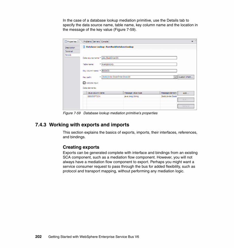
In the case of a database lookup mediation primitive, use the Details tab to specify the data source name, table name, key column name and the location in the message of the key value (Figure 7-59).
Figure 7-59 Database lookup mediation primitive’s properties
7.4.3 Working with exports and importsThis section explains the basics of exports, imports, their interfaces, references, and bindings.
Creating exportsExports can be generated complete with interface and bindings from an existing SCA component, such as a mediation flow component. However, you will not always have a mediation flow component to export. Perhaps you might want a service consumer request to pass through the bus for added flexibility, such as protocol and transport mapping, without performing any mediation logic.
202 Getting Started with WebSphere Enterprise Service Bus V6
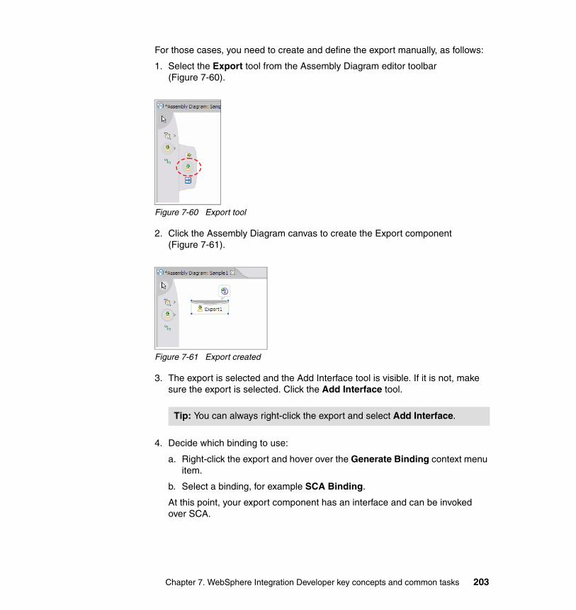
For those cases, you need to create and define the export manually, as follows:
1. Select the Export tool from the Assembly Diagram editor toolbar (Figure 7-60).
Figure 7-60 Export tool
2. Click the Assembly Diagram canvas to create the Export component (Figure 7-61).
Figure 7-61 Export created
3. The export is selected and the Add Interface tool is visible. If it is not, make sure the export is selected. Click the Add Interface tool.
4. Decide which binding to use:
a. Right-click the export and hover over the Generate Binding context menu item.
b. Select a binding, for example SCA Binding.
At this point, your export component has an interface and can be invoked over SCA.
Tip: You can always right-click the export and select Add Interface.
Chapter 7. WebSphere Integration Developer key concepts and common tasks 203
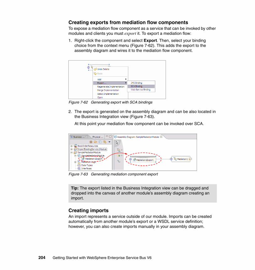
Creating exports from mediation flow componentsTo expose a mediation flow component as a service that can be invoked by other modules and clients you must export it. To export a mediation flow:
1. Right-click the component and select Export. Then, select your binding choice from the context menu (Figure 7-62). This adds the export to the assembly diagram and wires it to the mediation flow component.
Figure 7-62 Generating export with SCA bindings
2. The export is generated on the assembly diagram and can be also located in the Business Integration view (Figure 7-63).
At this point your mediation flow component can be invoked over SCA.
Figure 7-63 Generating mediation component export
Creating importsAn import represents a service outside of our module. Imports can be created automatically from another module’s export or a WSDL service definition; however, you can also create imports manually in your assembly diagram.
Tip: The export listed in the Business Integration view can be dragged and dropped into the canvas of another module’s assembly diagram creating an import.
204 Getting Started with WebSphere Enterprise Service Bus V6
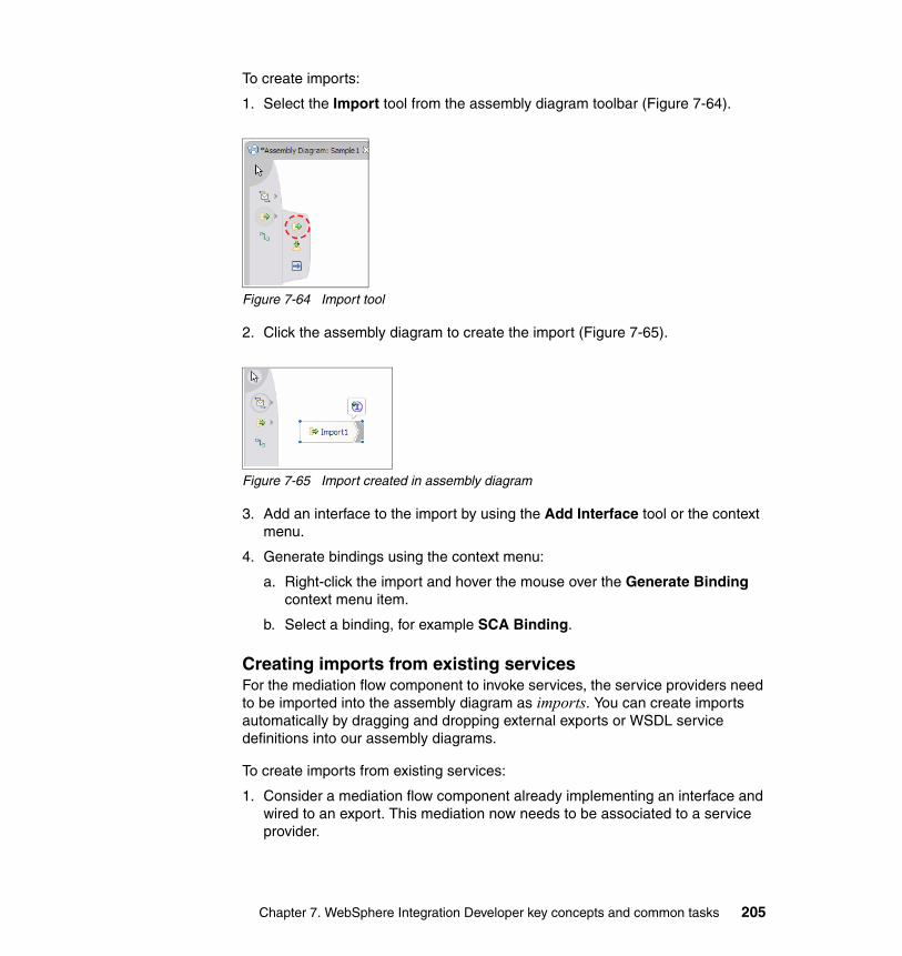
To create imports:
1. Select the Import tool from the assembly diagram toolbar (Figure 7-64).
Figure 7-64 Import tool
2. Click the assembly diagram to create the import (Figure 7-65).
Figure 7-65 Import created in assembly diagram
3. Add an interface to the import by using the Add Interface tool or the context menu.
4. Generate bindings using the context menu:
a. Right-click the import and hover the mouse over the Generate Binding context menu item.
b. Select a binding, for example SCA Binding.
Creating imports from existing servicesFor the mediation flow component to invoke services, the service providers need to be imported into the assembly diagram as imports. You can create imports automatically by dragging and dropping external exports or WSDL service definitions into our assembly diagrams.
To create imports from existing services:
1. Consider a mediation flow component already implementing an interface and wired to an export. This mediation now needs to be associated to a service provider.
Chapter 7. WebSphere Integration Developer key concepts and common tasks 205
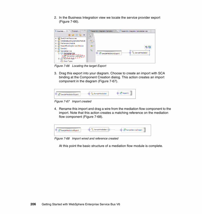
2. In the Business Integration view we locate the service provider export (Figure 7-66).
Figure 7-66 Locating the target Export
3. Drag this export into your diagram. Choose to create an import with SCA binding at the Component Creation dialog. This action creates an import component in the diagram (Figure 7-67).
Figure 7-67 Import created
4. Rename this import and drag a wire from the mediation flow component to the import. Note that this action creates a matching reference on the mediation flow component (Figure 7-68).
Figure 7-68 Import wired and reference created
At this point the basic structure of a mediation flow module is complete.
206 Getting Started with WebSphere Enterprise Service Bus V6
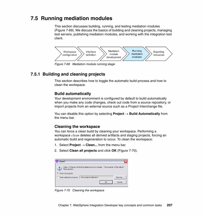
7.5 Running mediation modulesThis section discusses building, running, and testing mediation modules (Figure 7-69). We discuss the basics of building and cleaning projects, managing test servers, publishing mediation modules, and working with the integration test client.
Figure 7-69 Mediation module running stage
7.5.1 Building and cleaning projectsThis section describes how to toggle the automatic build process and how to clean the workspace.
Build automaticallyYour development environment is configured by default to build automatically when you make any code changes, check out code from a source repository, or import projects from an external source such as a Project Interchange file.
You can disable this option by selecting Project → Build Automatically from the menu bar.
Cleaning the workspaceYou can force a clean build by cleaning your workspace. Performing a workspace clean deletes all derived artifacts and staging projects, forcing an automatic build and regeneration to occur. To clean the workspace:
1. Select Project → Clean... from the menu bar.
2. Select Clean all projects and click OK (Figure 7-70).
Figure 7-70 Cleaning the workspace
Chapter 7. WebSphere Integration Developer key concepts and common tasks 207

7.5.2 Managing test serversThis section discusses the details of the test environment included in IBM WebSphere Integration Developer, how to set up different server configurations, and the tools that are used to publish applications. It also discusses how the development environment works with the server configurations.
Server profilesA server profile is a configuration that describes the runtime environment and includes all of the files required by the server at runtime. Creating profiles enables multiple servers to be configured from a single installation of WebSphere Enterprise Service Bus.
There are three types of profiles:
� Stand-alone
Hosts mediation modules and is the default WebSphere Enterprise Service Bus profile type.
� Managed node
Performs the same function as a stand-alone server but all administrative tasks for this profile are managed by a deployment manager.
� Deployment manager
Used to administer all managed nodes in a multi-node, multi-machine group, known as a cell.
For information about configuring each of these server profile types, see Chapter 5, “Setting up the runtime environment” on page 89.
208 Getting Started with WebSphere Enterprise Service Bus V6
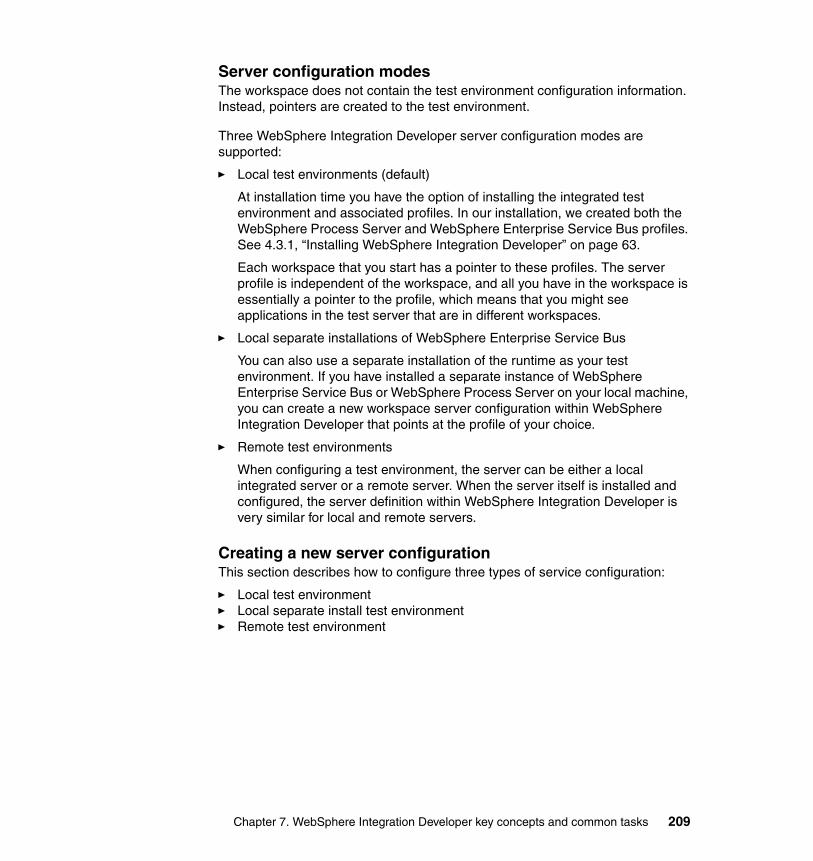
Server configuration modesThe workspace does not contain the test environment configuration information. Instead, pointers are created to the test environment.
Three WebSphere Integration Developer server configuration modes are supported:
� Local test environments (default)
At installation time you have the option of installing the integrated test environment and associated profiles. In our installation, we created both the WebSphere Process Server and WebSphere Enterprise Service Bus profiles. See 4.3.1, “Installing WebSphere Integration Developer” on page 63.
Each workspace that you start has a pointer to these profiles. The server profile is independent of the workspace, and all you have in the workspace is essentially a pointer to the profile, which means that you might see applications in the test server that are in different workspaces.
� Local separate installations of WebSphere Enterprise Service Bus
You can also use a separate installation of the runtime as your test environment. If you have installed a separate instance of WebSphere Enterprise Service Bus or WebSphere Process Server on your local machine, you can create a new workspace server configuration within WebSphere Integration Developer that points at the profile of your choice.
� Remote test environments
When configuring a test environment, the server can be either a local integrated server or a remote server. When the server itself is installed and configured, the server definition within WebSphere Integration Developer is very similar for local and remote servers.
Creating a new server configurationThis section describes how to configure three types of service configuration:
� Local test environment� Local separate install test environment� Remote test environment
Chapter 7. WebSphere Integration Developer key concepts and common tasks 209
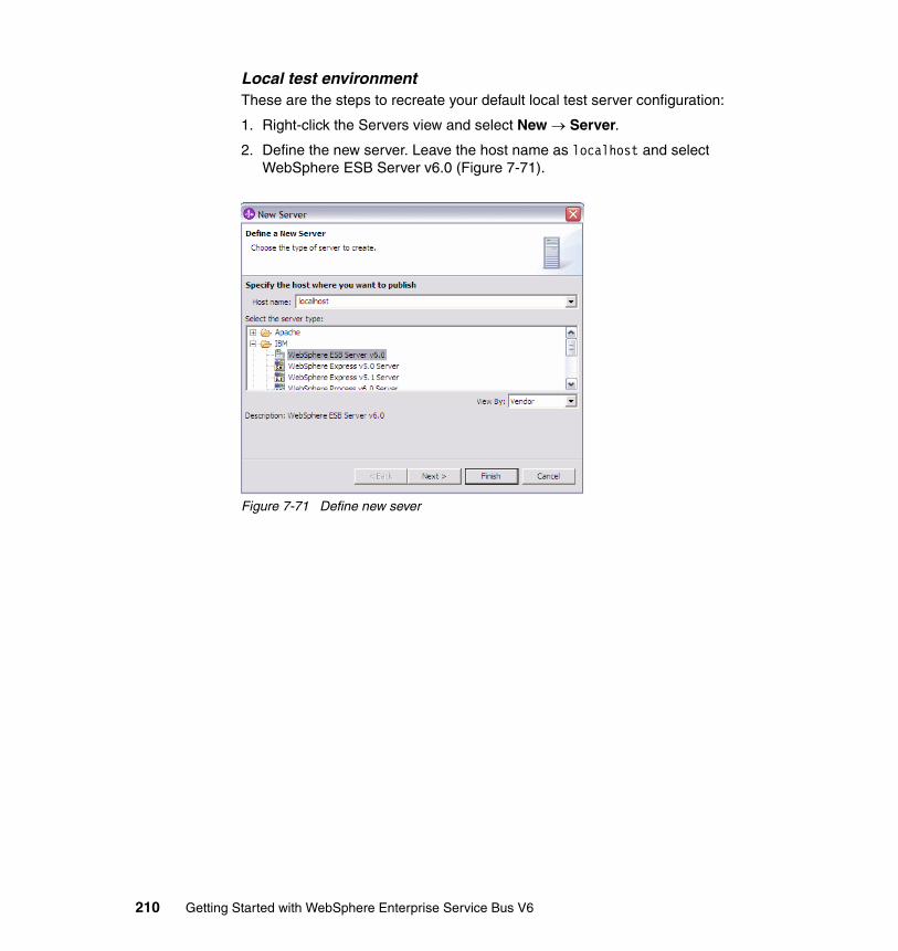
Local test environmentThese are the steps to recreate your default local test server configuration:
1. Right-click the Servers view and select New → Server.
2. Define the new server. Leave the host name as localhost and select WebSphere ESB Server v6.0 (Figure 7-71).
Figure 7-71 Define new sever
210 Getting Started with WebSphere Enterprise Service Bus V6
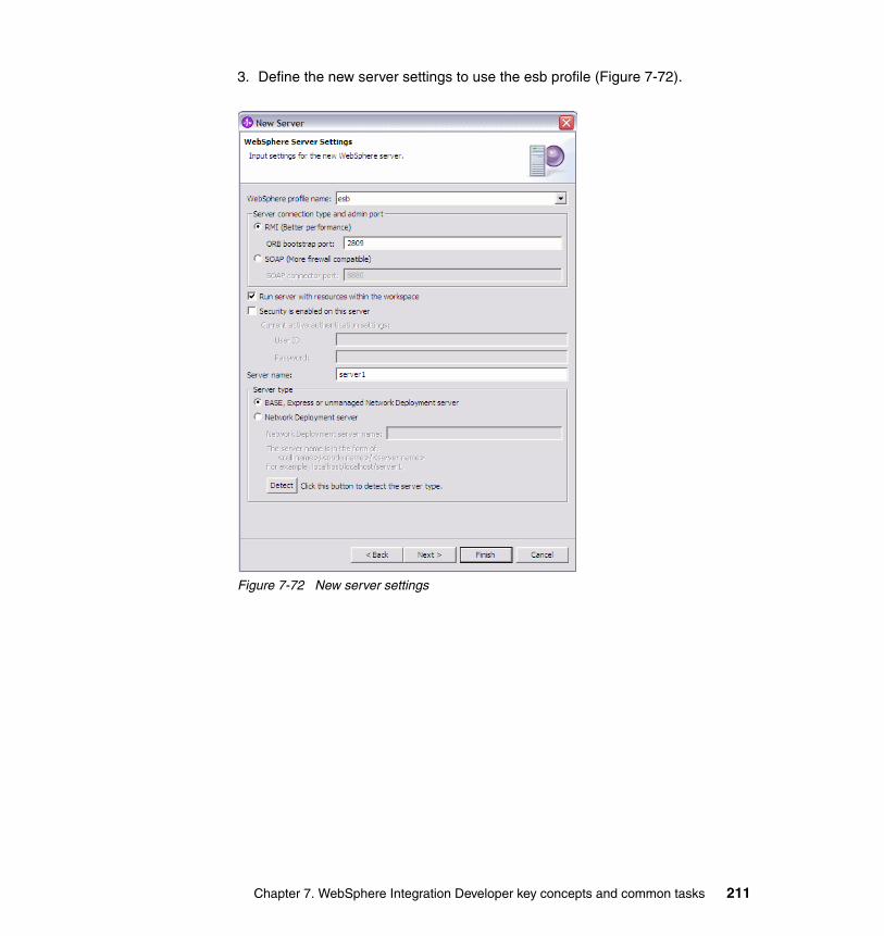
3. Define the new server settings to use the esb profile (Figure 7-72).
Figure 7-72 New server settings
Chapter 7. WebSphere Integration Developer key concepts and common tasks 211
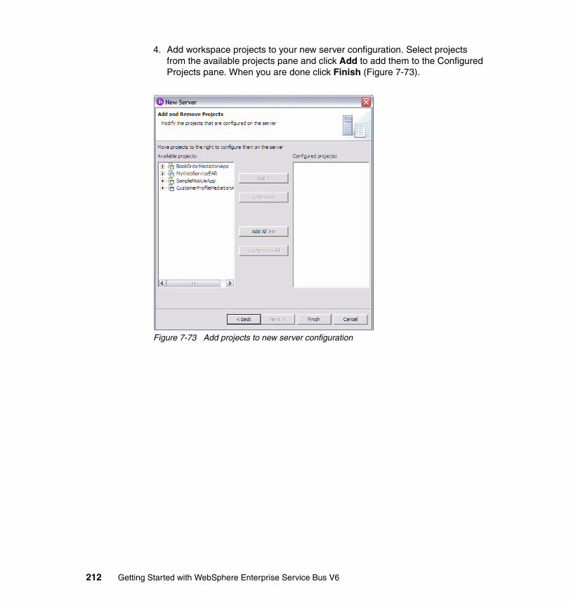
4. Add workspace projects to your new server configuration. Select projects from the available projects pane and click Add to add them to the Configured Projects pane. When you are done click Finish (Figure 7-73).
Figure 7-73 Add projects to new server configuration
212 Getting Started with WebSphere Enterprise Service Bus V6
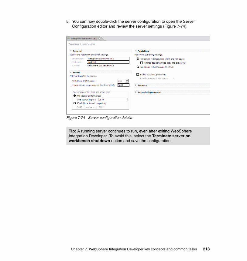
5. You can now double-click the server configuration to open the Server Configuration editor and review the server settings (Figure 7-74).
Figure 7-74 Server configuration details
Tip: A running server continues to run, even after exiting WebSphere Integration Developer. To avoid this, select the Terminate server on workbench shutdown option and save the configuration.
Chapter 7. WebSphere Integration Developer key concepts and common tasks 213
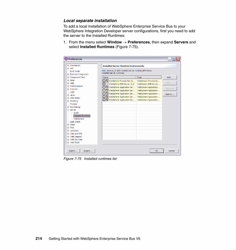
Local separate installationTo add a local installation of WebSphere Enterprise Service Bus to your WebSphere Integration Developer server configurations, first you need to add the server to the Installed Runtimes:
1. From the menu select Window → Preferences, then expand Servers and select Installed Runtimes (Figure 7-75).
Figure 7-75 Installed runtimes list
214 Getting Started with WebSphere Enterprise Service Bus V6
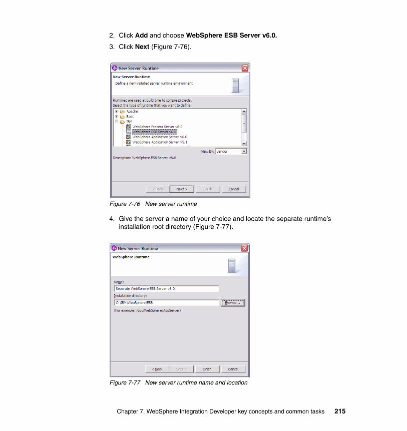
2. Click Add and choose WebSphere ESB Server v6.0.
3. Click Next (Figure 7-76).
Figure 7-76 New server runtime
4. Give the server a name of your choice and locate the separate runtime’s installation root directory (Figure 7-77).
Figure 7-77 New server runtime name and location
Chapter 7. WebSphere Integration Developer key concepts and common tasks 215
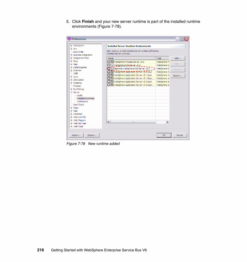
5. Click Finish and your new server runtime is part of the installed runtime environments (Figure 7-78).
Figure 7-78 New runtime added
216 Getting Started with WebSphere Enterprise Service Bus V6
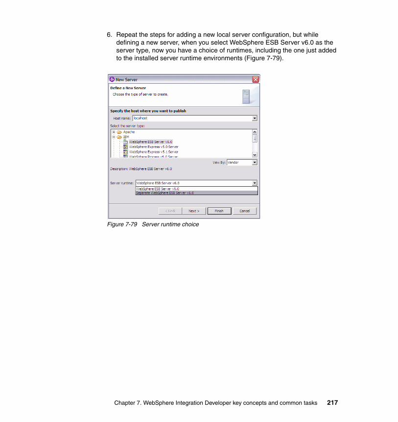
6. Repeat the steps for adding a new local server configuration, but while defining a new server, when you select WebSphere ESB Server v6.0 as the server type, now you have a choice of runtimes, including the one just added to the installed server runtime environments (Figure 7-79).
Figure 7-79 Server runtime choice
Chapter 7. WebSphere Integration Developer key concepts and common tasks 217
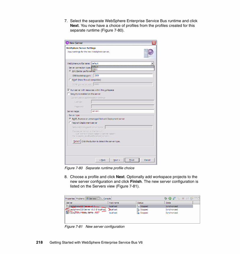
7. Select the separate WebSphere Enterprise Service Bus runtime and click Next. You now have a choice of profiles from the profiles created for this separate runtime (Figure 7-80).
Figure 7-80 Separate runtime profile choice
8. Choose a profile and click Next. Optionally add workspace projects to the new server configuration and click Finish. The new server configuration is listed on the Servers view (Figure 7-81).
Figure 7-81 New server configuration
218 Getting Started with WebSphere Enterprise Service Bus V6
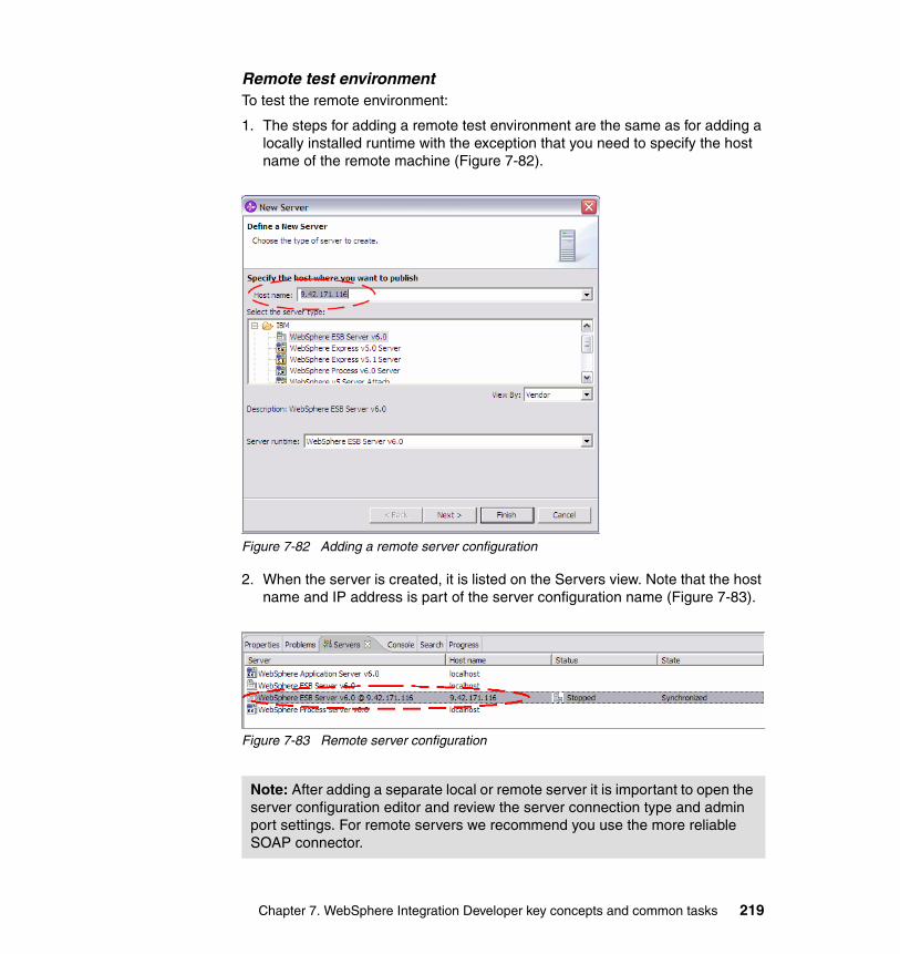
Remote test environmentTo test the remote environment:
1. The steps for adding a remote test environment are the same as for adding a locally installed runtime with the exception that you need to specify the host name of the remote machine (Figure 7-82).
Figure 7-82 Adding a remote server configuration
2. When the server is created, it is listed on the Servers view. Note that the host name and IP address is part of the server configuration name (Figure 7-83).
Figure 7-83 Remote server configuration
Note: After adding a separate local or remote server it is important to open the server configuration editor and review the server connection type and admin port settings. For remote servers we recommend you use the more reliable SOAP connector.
Chapter 7. WebSphere Integration Developer key concepts and common tasks 219

Commands to manage test serversWhen the server is configured, there are a few key commands to be aware of that are used to manage the test servers.
� Debug: only available for local test servers.
� Start: only available for local test servers.
� Restart: available on all active servers.
– Can restart in different modes (normal, debug, and profile).
� Stop
Figure 7-84 Servers view toolbar
Starting and stopping the serverThis section describes how to start and to stop the test environment server in the Servers view.
Starting the serverTo start the server:
1. In the Servers view, right-click the server that you want to start and select Start.
2. The console view comes to the foreground and displays logging information.
3. Wait until the Server server1 open for e-business message appears in the console and the server status in the Servers view is Started (Figure 7-85).
Figure 7-85 Server status
Tip: You can access the most commonly used server commands from the Servers view toolbar (Figure 7-84).
220 Getting Started with WebSphere Enterprise Service Bus V6

Stopping the serverTo stop the server:
1. In the Servers view, right-click the server that you want to stop and select Stop.
2. Wait until the server status is Stopped in the Servers view.
Starting the server in debug modeIf you want to debug code deployed to your test server, you need to start the server in debug mode:
1. Click the Debug tool on the Servers view toolbar or right-click the server and select Debug.
2. When the operation completes the server status in the Servers view should be Debugging (Figure 7-86).
Figure 7-86 Server started in debug mode
For more information about debugging, refer to 8.2, “Debugging tools” on page 243.
Running the administrative consoleYou can run the administrative console for a running server from within WebSphere Integration Developer. To do so:
1. Right-click the server and select Run administrative console from the context menu.
2. Click Log In to enter the console. Security is not enabled in the test environment.
Note: You might see a system error about the system not being able to find the file cell-wbi.xml. You can ignore this error safely.
Tip: If the server is already running, a quick way to switch to debug mode is to right-click the server and select Restart → Debug.
Chapter 7. WebSphere Integration Developer key concepts and common tasks 221
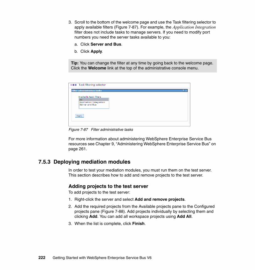
3. Scroll to the bottom of the welcome page and use the Task filtering selector to apply available filters (Figure 7-87). For example, the Application Integration filter does not include tasks to manage servers. If you need to modify port numbers you need the server tasks available to you:
a. Click Server and Bus.
b. Click Apply.
Figure 7-87 Filter administrative tasks
For more information about administering WebSphere Enterprise Service Bus resources see Chapter 9, “Administering WebSphere Enterprise Service Bus” on page 261.
7.5.3 Deploying mediation modulesIn order to test your mediation modules, you must run them on the test server. This section describes how to add and remove projects to the test server.
Adding projects to the test serverTo add projects to the test server:
1. Right-click the server and select Add and remove projects.
2. Add the required projects from the Available projects pane to the Configured projects pane (Figure 7-88). Add projects individually by selecting them and clicking Add. You can add all workspace projects using Add All.
3. When the list is complete, click Finish.
Tip: You can change the filter at any time by going back to the welcome page. Click the Welcome link at the top of the administrative console menu.
222 Getting Started with WebSphere Enterprise Service Bus V6
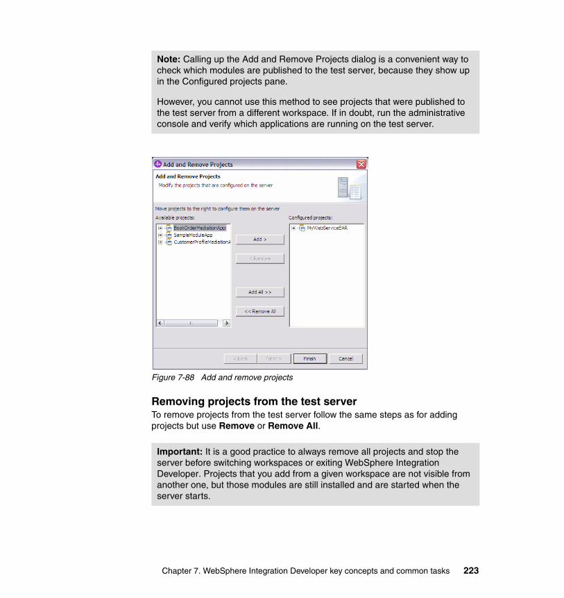
Figure 7-88 Add and remove projects
Removing projects from the test serverTo remove projects from the test server follow the same steps as for adding projects but use Remove or Remove All.
Note: Calling up the Add and Remove Projects dialog is a convenient way to check which modules are published to the test server, because they show up in the Configured projects pane.
However, you cannot use this method to see projects that were published to the test server from a different workspace. If in doubt, run the administrative console and verify which applications are running on the test server.
Important: It is a good practice to always remove all projects and stop the server before switching workspaces or exiting WebSphere Integration Developer. Projects that you add from a given workspace are not visible from another one, but those modules are still installed and are started when the server starts.
Chapter 7. WebSphere Integration Developer key concepts and common tasks 223
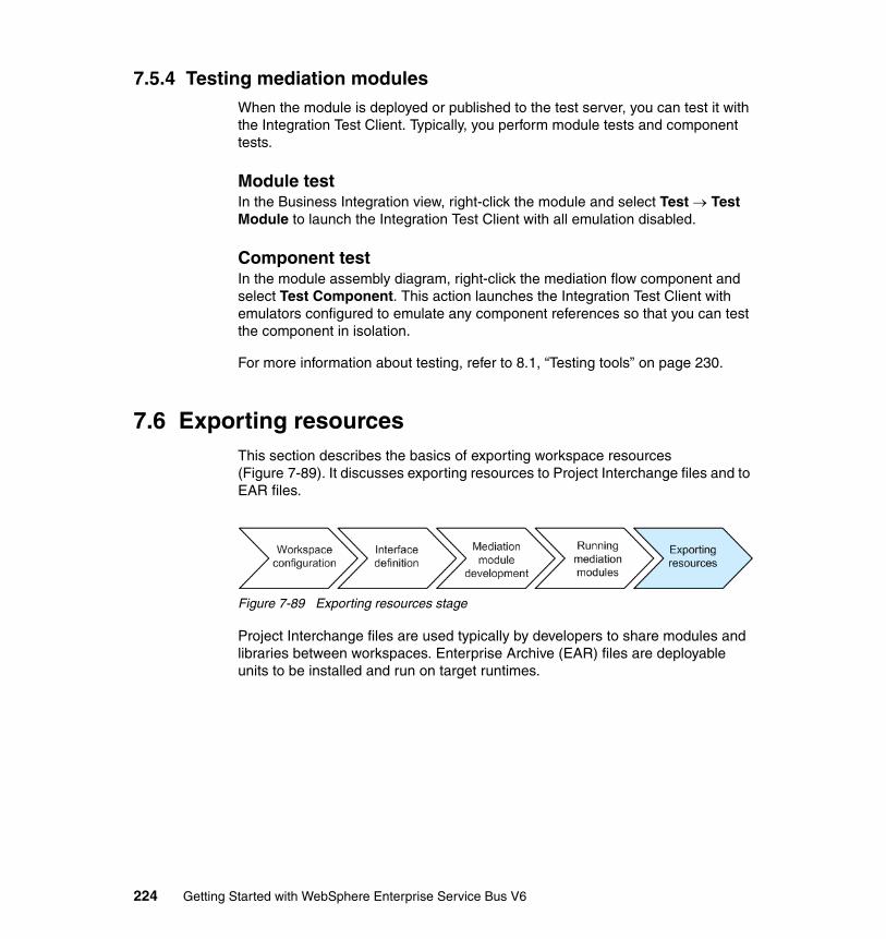
7.5.4 Testing mediation modulesWhen the module is deployed or published to the test server, you can test it with the Integration Test Client. Typically, you perform module tests and component tests.
Module testIn the Business Integration view, right-click the module and select Test → Test Module to launch the Integration Test Client with all emulation disabled.
Component testIn the module assembly diagram, right-click the mediation flow component and select Test Component. This action launches the Integration Test Client with emulators configured to emulate any component references so that you can test the component in isolation.
For more information about testing, refer to 8.1, “Testing tools” on page 230.
7.6 Exporting resourcesThis section describes the basics of exporting workspace resources (Figure 7-89). It discusses exporting resources to Project Interchange files and to EAR files.
Figure 7-89 Exporting resources stage
Project Interchange files are used typically by developers to share modules and libraries between workspaces. Enterprise Archive (EAR) files are deployable units to be installed and run on target runtimes.
224 Getting Started with WebSphere Enterprise Service Bus V6
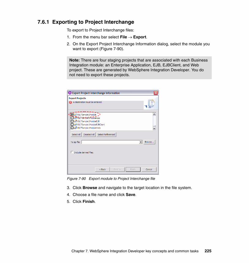
7.6.1 Exporting to Project InterchangeTo export to Project Interchange files:
1. From the menu bar select File → Export.
2. On the Export Project Interchange Information dialog, select the module you want to export (Figure 7-90).
Figure 7-90 Export module to Project Interchange file
3. Click Browse and navigate to the target location in the file system.
4. Choose a file name and click Save.
5. Click Finish.
Note: There are four staging projects that are associated with each Business Integration module: an Enterprise Application, EJB, EJBClient, and Web project. These are generated by WebSphere Integration Developer. You do not need to export these projects.
Chapter 7. WebSphere Integration Developer key concepts and common tasks 225
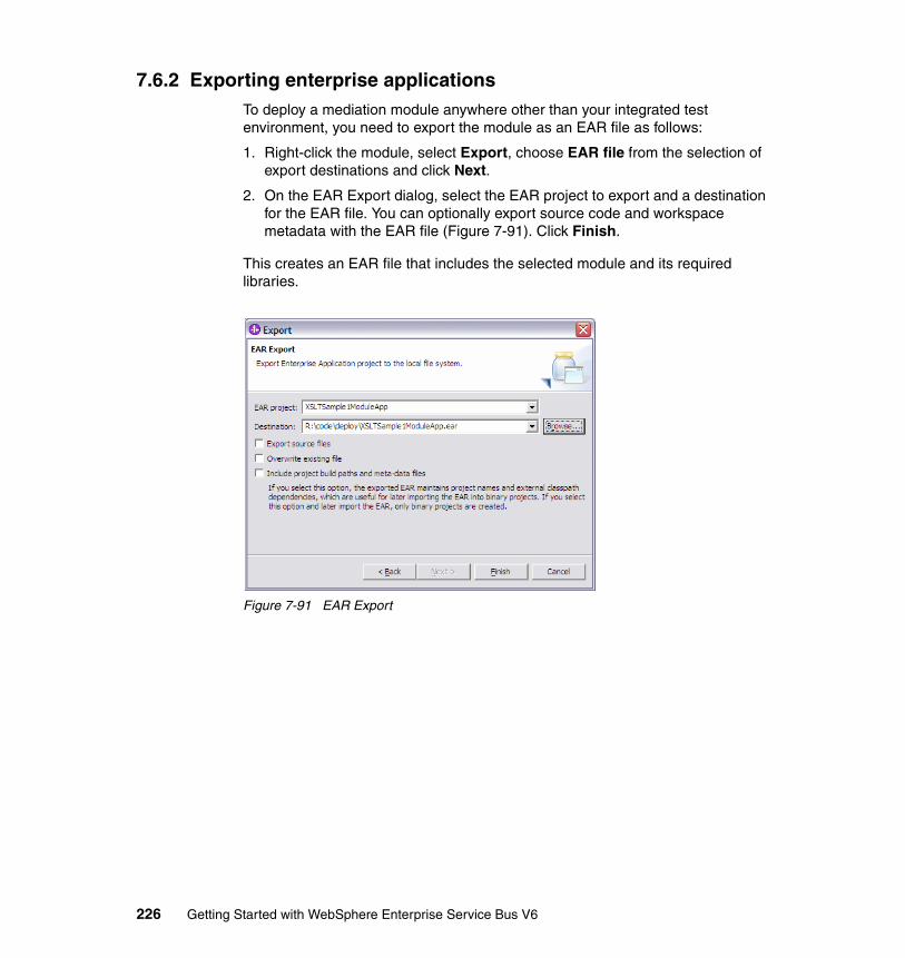
7.6.2 Exporting enterprise applicationsTo deploy a mediation module anywhere other than your integrated test environment, you need to export the module as an EAR file as follows:
1. Right-click the module, select Export, choose EAR file from the selection of export destinations and click Next.
2. On the EAR Export dialog, select the EAR project to export and a destination for the EAR file. You can optionally export source code and workspace metadata with the EAR file (Figure 7-91). Click Finish.
This creates an EAR file that includes the selected module and its required libraries.
Figure 7-91 EAR Export
226 Getting Started with WebSphere Enterprise Service Bus V6
Part 3 Administration and testing
Part 3
© Copyright IBM Corp. 2006. All rights reserved. 227

228 Getting Started with WebSphere Enterprise Service Bus V6

Chapter 8. Testing, debugging and problem determination
This chapter discusses the techniques and tools that are available to test the artifacts that you develop for WebSphere Enterprise Service Bus and to perform troubleshooting in the runtime environment. We look at the test tools in WebSphere Integration Developer and techniques for isolating code problems in development. We also discuss how you can perform problem determination in the more advanced test stages and in the production environment, using the capabilities of the WebSphere Enterprise Service Bus runtime. It includes the following sections:
� Testing tools� Debugging tools� Problem determination facilities
8
© Copyright IBM Corp. 2006. All rights reserved. 229
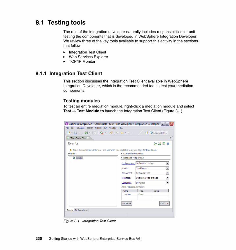
8.1 Testing toolsThe role of the integration developer naturally includes responsibilities for unit testing the components that is developed in WebSphere Integration Developer. We review three of the key tools available to support this activity in the sections that follow:
� Integration Test Client� Web Services Explorer� TCP/IP Monitor
8.1.1 Integration Test ClientThis section discusses the Integration Test Client available in WebSphere Integration Developer, which is the recommended tool to test your mediation components.
Testing modulesTo test an entire mediation module, right-click a mediation module and select Test → Test Module to launch the Integration Test Client (Figure 8-1).
Figure 8-1 Integration Test Client
230 Getting Started with WebSphere Enterprise Service Bus V6
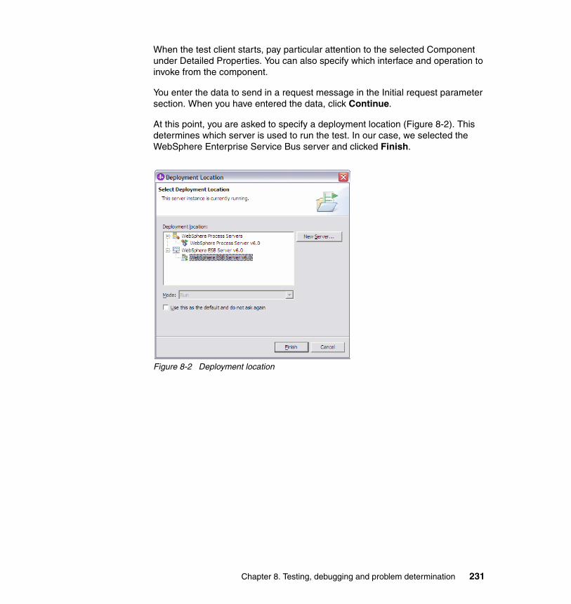
When the test client starts, pay particular attention to the selected Component under Detailed Properties. You can also specify which interface and operation to invoke from the component.
You enter the data to send in a request message in the Initial request parameter section. When you have entered the data, click Continue.
At this point, you are asked to specify a deployment location (Figure 8-2). This determines which server is used to run the test. In our case, we selected the WebSphere Enterprise Service Bus server and clicked Finish.
Figure 8-2 Deployment location
Chapter 8. Testing, debugging and problem determination 231
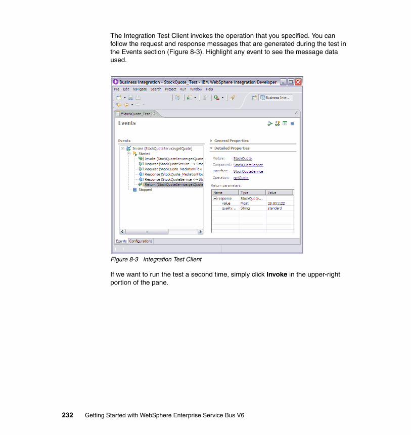
The Integration Test Client invokes the operation that you specified. You can follow the request and response messages that are generated during the test in the Events section (Figure 8-3). Highlight any event to see the message data used.
Figure 8-3 Integration Test Client
If we want to run the test a second time, simply click Invoke in the upper-right portion of the pane.
232 Getting Started with WebSphere Enterprise Service Bus V6
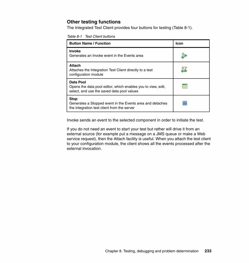
Other testing functionsThe Integrated Test Client provides four buttons for testing (Table 8-1).
Table 8-1 Test Client buttons
Invoke sends an event to the selected component in order to initiate the test.
If you do not need an event to start your test but rather will drive it from an external source (for example put a message on a JMS queue or make a Web service request), then the Attach facility is useful. When you attach the test client to your configuration module, the client shows all the events processed after the external invocation.
Button Name / Function Icon
InvokeGenerates an Invoke event in the Events area
AttachAttaches the Integration Test Client directly to a test configuration module
Data PoolOpens the data pool editor, which enables you to view, edit, select, and use the saved data pool values
StopGenerates a Stopped event in the Events area and detaches the integration test client from the server
Chapter 8. Testing, debugging and problem determination 233
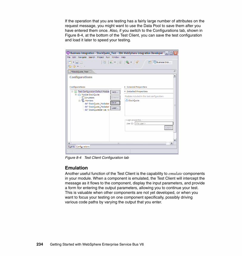
If the operation that you are testing has a fairly large number of attributes on the request message, you might want to use the Data Pool to save them after you have entered them once. Also, if you switch to the Configurations tab, shown in Figure 8-4, at the bottom of the Test Client, you can save the test configuration and load it later to speed your testing.
Figure 8-4 Test Client Configuration tab
EmulationAnother useful function of the Test Client is the capability to emulate components in your module. When a component is emulated, the Test Client will intercept the message as it flows to the component, display the input parameters, and provide a form for entering the output parameters, allowing you to continue your test. This is valuable when other components are not yet developed, or when you want to focus your testing on one component specifically, possibly driving various code paths by varying the output that you enter.
234 Getting Started with WebSphere Enterprise Service Bus V6
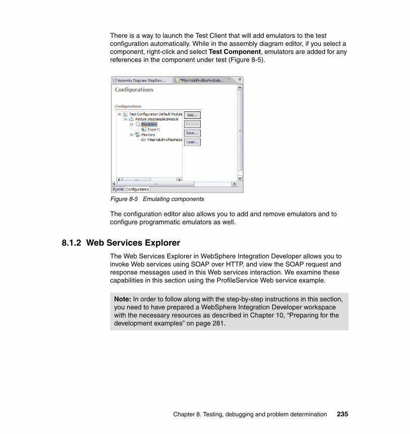
There is a way to launch the Test Client that will add emulators to the test configuration automatically. While in the assembly diagram editor, if you select a component, right-click and select Test Component, emulators are added for any references in the component under test (Figure 8-5).
Figure 8-5 Emulating components
The configuration editor also allows you to add and remove emulators and to configure programmatic emulators as well.
8.1.2 Web Services ExplorerThe Web Services Explorer in WebSphere Integration Developer allows you to invoke Web services using SOAP over HTTP, and view the SOAP request and response messages used in this Web services interaction. We examine these capabilities in this section using the ProfileService Web service example.
Note: In order to follow along with the step-by-step instructions in this section, you need to have prepared a WebSphere Integration Developer workspace with the necessary resources as described in Chapter 10, “Preparing for the development examples” on page 281.
Chapter 8. Testing, debugging and problem determination 235
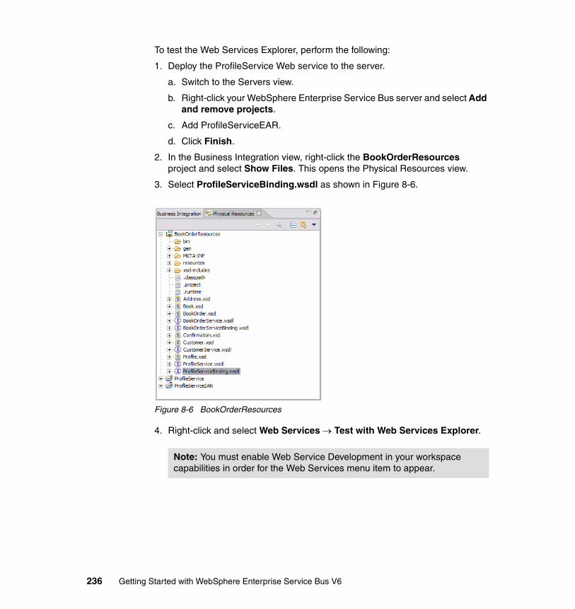
To test the Web Services Explorer, perform the following:
1. Deploy the ProfileService Web service to the server.
a. Switch to the Servers view.
b. Right-click your WebSphere Enterprise Service Bus server and select Add and remove projects.
c. Add ProfileServiceEAR.
d. Click Finish.
2. In the Business Integration view, right-click the BookOrderResources project and select Show Files. This opens the Physical Resources view.
3. Select ProfileServiceBinding.wsdl as shown in Figure 8-6.
Figure 8-6 BookOrderResources
4. Right-click and select Web Services → Test with Web Services Explorer.
Note: You must enable Web Service Development in your workspace capabilities in order for the Web Services menu item to appear.
236 Getting Started with WebSphere Enterprise Service Bus V6
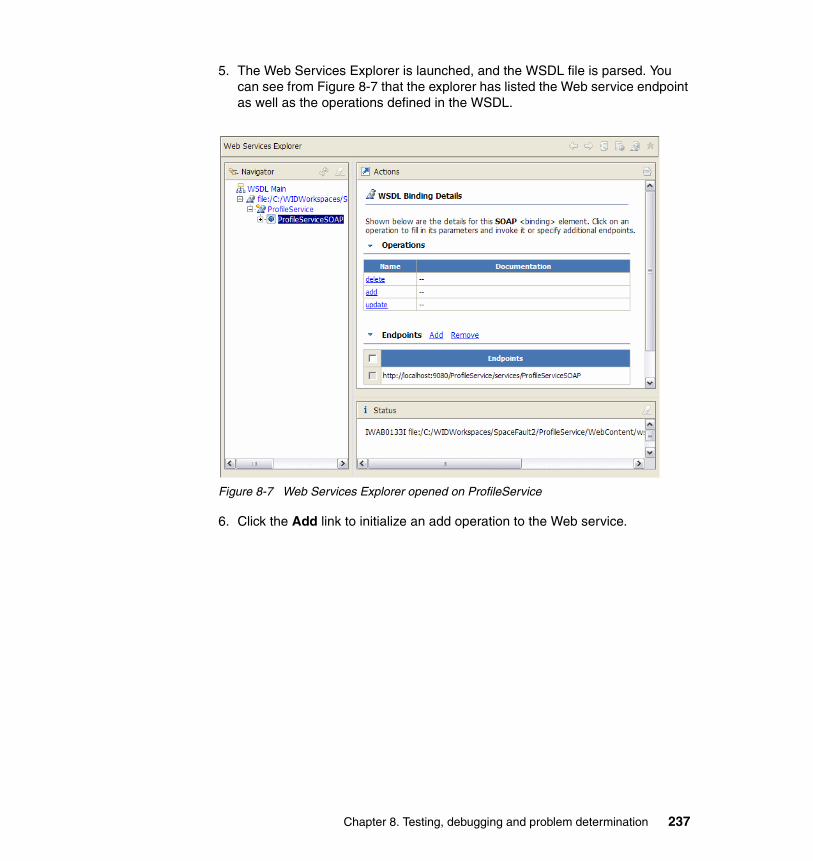
5. The Web Services Explorer is launched, and the WSDL file is parsed. You can see from Figure 8-7 that the explorer has listed the Web service endpoint as well as the operations defined in the WSDL.
Figure 8-7 Web Services Explorer opened on ProfileService
6. Click the Add link to initialize an add operation to the Web service.
Chapter 8. Testing, debugging and problem determination 237
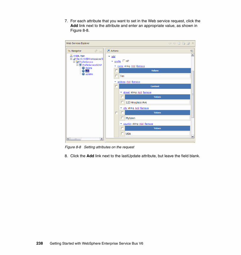
7. For each attribute that you want to set in the Web service request, click the Add link next to the attribute and enter an appropriate value, as shown in Figure 8-8.
Figure 8-8 Setting attributes on the request
8. Click the Add link next to the lastUpdate attribute, but leave the field blank.
238 Getting Started with WebSphere Enterprise Service Bus V6
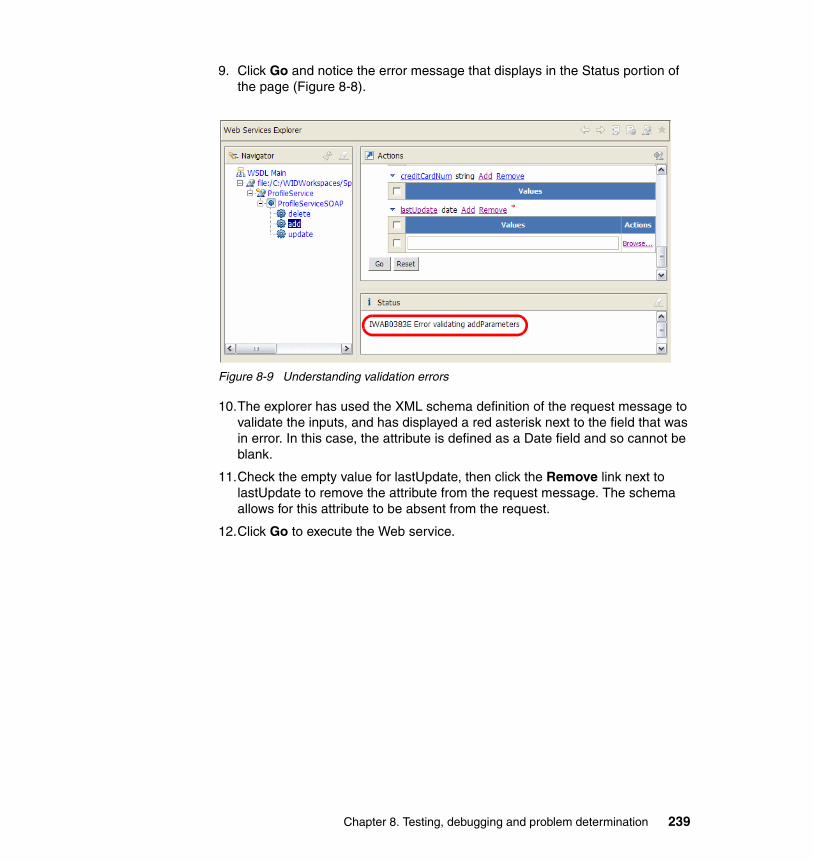
9. Click Go and notice the error message that displays in the Status portion of the page (Figure 8-8).
Figure 8-9 Understanding validation errors
10.The explorer has used the XML schema definition of the request message to validate the inputs, and has displayed a red asterisk next to the field that was in error. In this case, the attribute is defined as a Date field and so cannot be blank.
11.Check the empty value for lastUpdate, then click the Remove link next to lastUpdate to remove the attribute from the request message. The schema allows for this attribute to be absent from the request.
12.Click Go to execute the Web service.
Chapter 8. Testing, debugging and problem determination 239
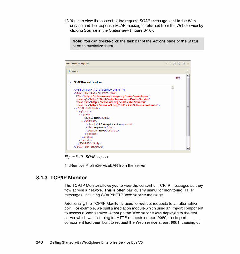
13.You can view the content of the request SOAP message sent to the Web service and the response SOAP messages returned from the Web service by clicking Source in the Status view (Figure 8-10).
Figure 8-10 SOAP request
14.Remove ProfileServiceEAR from the server.
8.1.3 TCP/IP MonitorThe TCP/IP Monitor allows you to view the content of TCP/IP messages as they flow across a network. This is often particularly useful for monitoring HTTP messages, including SOAP/HTTP Web service message.
Additionally, the TCP/IP Monitor is used to redirect requests to an alternative port. For example, we built a mediation module which used an Import component to access a Web service. Although the Web service was deployed to the test server which was listening for HTTP requests on port 9080, the Import component had been built to request the Web service at port 9081, causing our
Note: You can double-click the task bar of the Actions pane or the Status pane to maximize them.
240 Getting Started with WebSphere Enterprise Service Bus V6
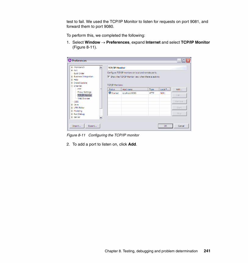
test to fail. We used the TCP/IP Monitor to listen for requests on port 9081, and forward them to port 9080.
To perform this, we completed the following:
1. Select Window → Preferences, expand Internet and select TCP/IP Monitor (Figure 8-11).
Figure 8-11 Configuring the TCP/IP monitor
2. To add a port to listen on, click Add.
Chapter 8. Testing, debugging and problem determination 241
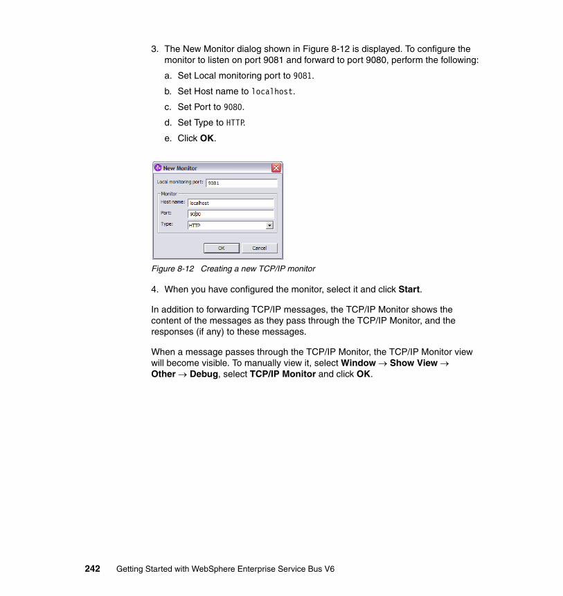
3. The New Monitor dialog shown in Figure 8-12 is displayed. To configure the monitor to listen on port 9081 and forward to port 9080, perform the following:
a. Set Local monitoring port to 9081.
b. Set Host name to localhost.
c. Set Port to 9080.
d. Set Type to HTTP.
e. Click OK.
Figure 8-12 Creating a new TCP/IP monitor
4. When you have configured the monitor, select it and click Start.
In addition to forwarding TCP/IP messages, the TCP/IP Monitor shows the content of the messages as they pass through the TCP/IP Monitor, and the responses (if any) to these messages.
When a message passes through the TCP/IP Monitor, the TCP/IP Monitor view will become visible. To manually view it, select Window → Show View → Other → Debug, select TCP/IP Monitor and click OK.
242 Getting Started with WebSphere Enterprise Service Bus V6
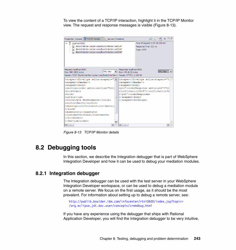
To view the content of a TCP/IP interaction, highlight it in the TCP/IP Monitor view. The request and response messages is visible (Figure 8-13).
Figure 8-13 TCP/IP Monitor details
8.2 Debugging toolsIn this section, we describe the Integration debugger that is part of WebSphere Integration Developer and how it can be used to debug your mediation modules.
8.2.1 Integration debuggerThe Integration debugger can be used with the test server in your WebSphere Integration Developer workspace, or can be used to debug a mediation module on a remote server. We focus on the first usage, as it should be the most prevalent. For information about setting up to debug a remote server, see:
http://publib.boulder.ibm.com/infocenter/rtnl0600/index.jsp?topic=/org.eclipse.jdt.doc.user/concepts/cremdbug.html
If you have any experience using the debugger that ships with Rational Application Developer, you will find the Integration debugger to be very intuitive,
Chapter 8. Testing, debugging and problem determination 243
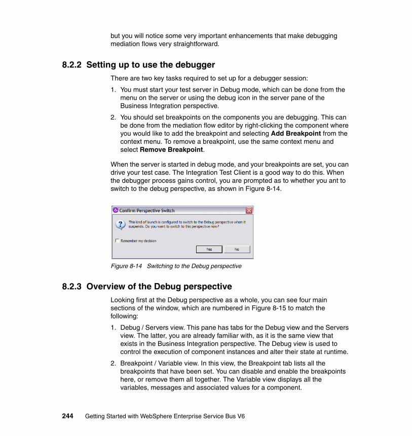
but you will notice some very important enhancements that make debugging mediation flows very straightforward.
8.2.2 Setting up to use the debuggerThere are two key tasks required to set up for a debugger session:
1. You must start your test server in Debug mode, which can be done from the menu on the server or using the debug icon in the server pane of the Business Integration perspective.
2. You should set breakpoints on the components you are debugging. This can be done from the mediation flow editor by right-clicking the component where you would like to add the breakpoint and selecting Add Breakpoint from the context menu. To remove a breakpoint, use the same context menu and select Remove Breakpoint.
When the server is started in debug mode, and your breakpoints are set, you can drive your test case. The Integration Test Client is a good way to do this. When the debugger process gains control, you are prompted as to whether you ant to switch to the debug perspective, as shown in Figure 8-14.
Figure 8-14 Switching to the Debug perspective
8.2.3 Overview of the Debug perspectiveLooking first at the Debug perspective as a whole, you can see four main sections of the window, which are numbered in Figure 8-15 to match the following:
1. Debug / Servers view. This pane has tabs for the Debug view and the Servers view. The latter, you are already familiar with, as it is the same view that exists in the Business Integration perspective. The Debug view is used to control the execution of component instances and alter their state at runtime.
2. Breakpoint / Variable view. In this view, the Breakpoint tab lists all the breakpoints that have been set. You can disable and enable the breakpoints here, or remove them all together. The Variable view displays all the variables, messages and associated values for a component.
244 Getting Started with WebSphere Enterprise Service Bus V6
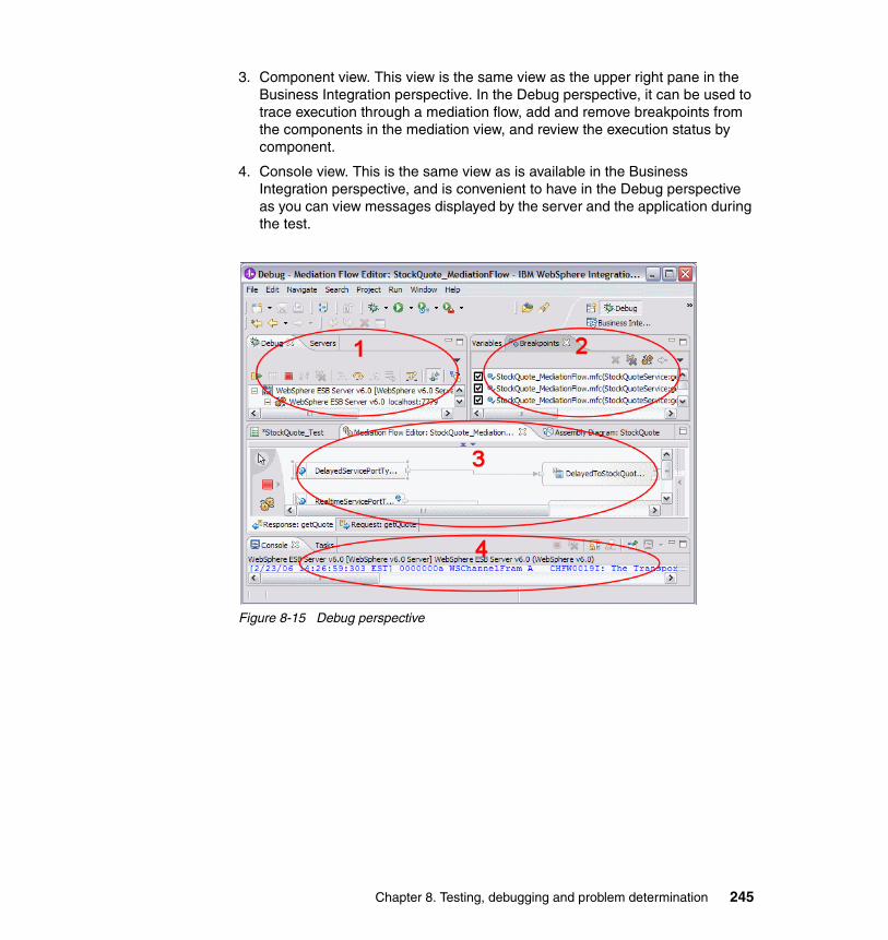
3. Component view. This view is the same view as the upper right pane in the Business Integration perspective. In the Debug perspective, it can be used to trace execution through a mediation flow, add and remove breakpoints from the components in the mediation view, and review the execution status by component.
4. Console view. This is the same view as is available in the Business Integration perspective, and is convenient to have in the Debug perspective as you can view messages displayed by the server and the application during the test.
Figure 8-15 Debug perspective
Chapter 8. Testing, debugging and problem determination 245
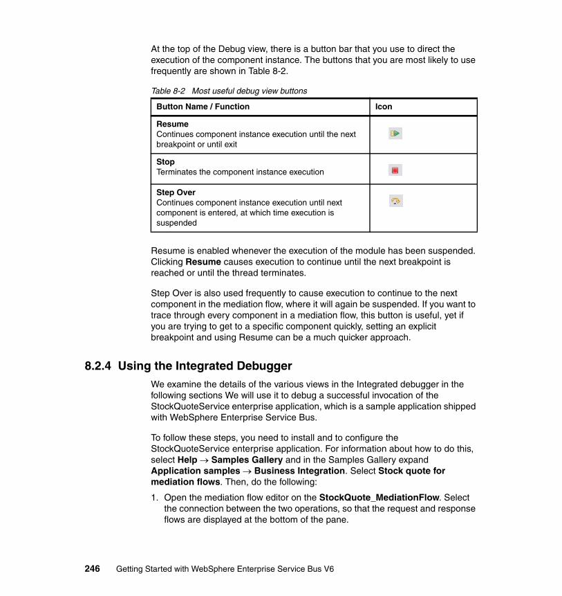
At the top of the Debug view, there is a button bar that you use to direct the execution of the component instance. The buttons that you are most likely to use frequently are shown in Table 8-2.
Table 8-2 Most useful debug view buttons
Resume is enabled whenever the execution of the module has been suspended. Clicking Resume causes execution to continue until the next breakpoint is reached or until the thread terminates.
Step Over is also used frequently to cause execution to continue to the next component in the mediation flow, where it will again be suspended. If you want to trace through every component in a mediation flow, this button is useful, yet if you are trying to get to a specific component quickly, setting an explicit breakpoint and using Resume can be a much quicker approach.
8.2.4 Using the Integrated DebuggerWe examine the details of the various views in the Integrated debugger in the following sections We will use it to debug a successful invocation of the StockQuoteService enterprise application, which is a sample application shipped with WebSphere Enterprise Service Bus.
To follow these steps, you need to install and to configure the StockQuoteService enterprise application. For information about how to do this, select Help → Samples Gallery and in the Samples Gallery expand Application samples → Business Integration. Select Stock quote for mediation flows. Then, do the following:
1. Open the mediation flow editor on the StockQuote_MediationFlow. Select the connection between the two operations, so that the request and response flows are displayed at the bottom of the pane.
Button Name / Function Icon
ResumeContinues component instance execution until the next breakpoint or until exit
StopTerminates the component instance execution
Step OverContinues component instance execution until next component is entered, at which time execution is suspended
246 Getting Started with WebSphere Enterprise Service Bus V6
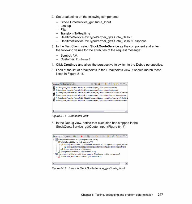
2. Set breakpoints on the following components:
– StockQuoteService_getQuote_Input– Lookup– Filter– TransformToRealtime– RealtimeServicePortTypePartner_getQuote_Callout– RealtimeServicePortTypePartner_getQuote_CalloutResponse
3. In the Test Client, select StockQuoteService as the component and enter the following values for the attributes of the request message:
– Symbol: AAA– Customer: CustomerB
4. Click Continue and allow the perspective to switch to the Debug perspective.
5. Look at the list of breakpoints in the Breakpoints view. It should match those listed in Figure 8-16.
Figure 8-16 Breakpoint view
6. In the Debug view, notice that execution has stopped in the StockQuoteService_getQuote_Input (Figure 8-17).
Figure 8-17 Break in StockQuoteService_getQuote_Input
Chapter 8. Testing, debugging and problem determination 247
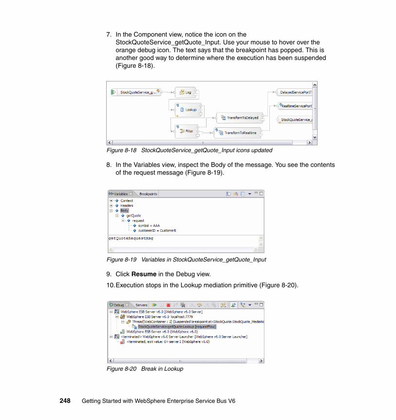
7. In the Component view, notice the icon on the StockQuoteService_getQuote_Input. Use your mouse to hover over the orange debug icon. The text says that the breakpoint has popped. This is another good way to determine where the execution has been suspended (Figure 8-18).
Figure 8-18 StockQuoteService_getQuote_Input icons updated
8. In the Variables view, inspect the Body of the message. You see the contents of the request message (Figure 8-19).
Figure 8-19 Variables in StockQuoteService_getQuote_Input
9. Click Resume in the Debug view.
10.Execution stops in the Lookup mediation primitive (Figure 8-20).
Figure 8-20 Break in Lookup
248 Getting Started with WebSphere Enterprise Service Bus V6
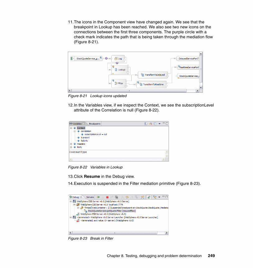
11.The icons in the Component view have changed again. We see that the breakpoint in Lookup has been reached. We also see two new icons on the connections between the first three components. The purple circle with a check mark indicates the path that is being taken through the mediation flow (Figure 8-21).
Figure 8-21 Lookup icons updated
12.In the Variables view, if we inspect the Context, we see the subscriptionLevel attribute of the Correlation is null (Figure 8-22).
Figure 8-22 Variables in Lookup
13.Click Resume in the Debug view.
14.Execution is suspended in the Filter mediation primitive (Figure 8-23).
Figure 8-23 Break in Filter
Chapter 8. Testing, debugging and problem determination 249
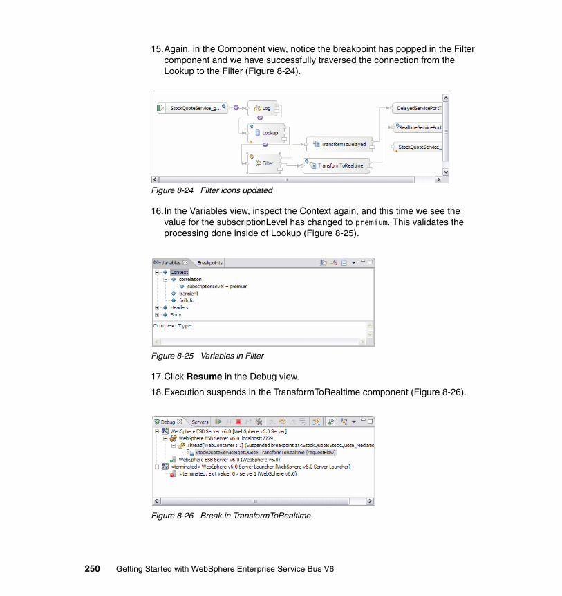
15.Again, in the Component view, notice the breakpoint has popped in the Filter component and we have successfully traversed the connection from the Lookup to the Filter (Figure 8-24).
Figure 8-24 Filter icons updated
16.In the Variables view, inspect the Context again, and this time we see the value for the subscriptionLevel has changed to premium. This validates the processing done inside of Lookup (Figure 8-25).
Figure 8-25 Variables in Filter
17.Click Resume in the Debug view.
18.Execution suspends in the TransformToRealtime component (Figure 8-26).
Figure 8-26 Break in TransformToRealtime
250 Getting Started with WebSphere Enterprise Service Bus V6
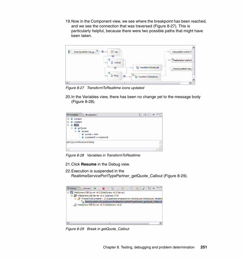
19.Now in the Component view, we see where the breakpoint has been reached, and we see the connection that was traversed (Figure 8-27). This is particularly helpful, because there were two possible paths that might have been taken.
Figure 8-27 TransformToRealtime icons updated
20.In the Variables view, there has been no change yet to the message body (Figure 8-28).
Figure 8-28 Variables in TransformToRealtime
21.Click Resume in the Debug view.
22.Execution is suspended in the RealtimeServicePortTypePartner_getQuote_Callout (Figure 8-29).
Figure 8-29 Break in getQuote_Callout
Chapter 8. Testing, debugging and problem determination 251
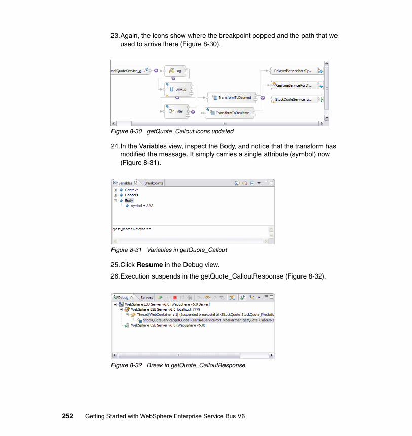
23.Again, the icons show where the breakpoint popped and the path that we used to arrive there (Figure 8-30).
Figure 8-30 getQuote_Callout icons updated
24.In the Variables view, inspect the Body, and notice that the transform has modified the message. It simply carries a single attribute (symbol) now (Figure 8-31).
Figure 8-31 Variables in getQuote_Callout
25.Click Resume in the Debug view.
26.Execution suspends in the getQuote_CalloutResponse (Figure 8-32).
Figure 8-32 Break in getQuote_CalloutResponse
252 Getting Started with WebSphere Enterprise Service Bus V6
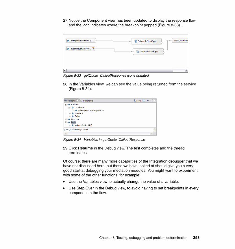
27.Notice the Component view has been updated to display the response flow, and the icon indicates where the breakpoint popped (Figure 8-33).
Figure 8-33 getQuote_CalloutResponse icons updated
28.In the Variables view, we can see the value being returned from the service (Figure 8-34).
Figure 8-34 Variables in getQuote_CalloutResponse
29.Click Resume in the Debug view. The test completes and the thread terminates.
Of course, there are many more capabilities of the Integration debugger that we have not discussed here, but those we have looked at should give you a very good start at debugging your mediation modules. You might want to experiment with some of the other functions, for example:
� Use the Variables view to actually change the value of a variable.
� Use Step Over in the Debug view, to avoid having to set breakpoints in every component in the flow.
Chapter 8. Testing, debugging and problem determination 253
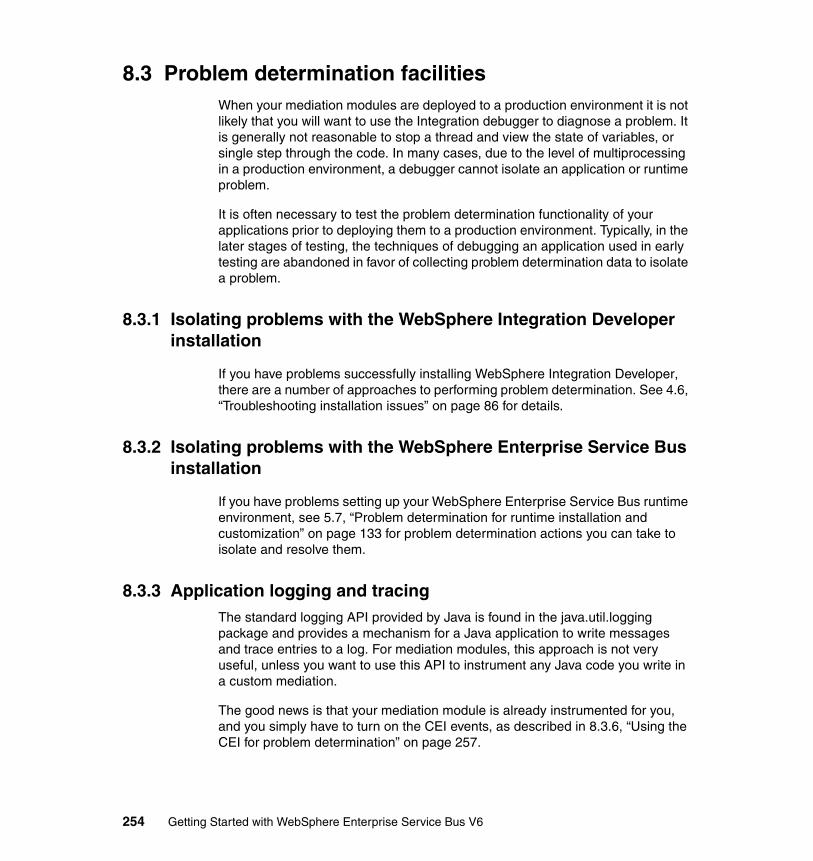
8.3 Problem determination facilitiesWhen your mediation modules are deployed to a production environment it is not likely that you will want to use the Integration debugger to diagnose a problem. It is generally not reasonable to stop a thread and view the state of variables, or single step through the code. In many cases, due to the level of multiprocessing in a production environment, a debugger cannot isolate an application or runtime problem.
It is often necessary to test the problem determination functionality of your applications prior to deploying them to a production environment. Typically, in the later stages of testing, the techniques of debugging an application used in early testing are abandoned in favor of collecting problem determination data to isolate a problem.
8.3.1 Isolating problems with the WebSphere Integration Developer installation
If you have problems successfully installing WebSphere Integration Developer, there are a number of approaches to performing problem determination. See 4.6, “Troubleshooting installation issues” on page 86 for details.
8.3.2 Isolating problems with the WebSphere Enterprise Service Bus installation
If you have problems setting up your WebSphere Enterprise Service Bus runtime environment, see 5.7, “Problem determination for runtime installation and customization” on page 133 for problem determination actions you can take to isolate and resolve them.
8.3.3 Application logging and tracingThe standard logging API provided by Java is found in the java.util.logging package and provides a mechanism for a Java application to write messages and trace entries to a log. For mediation modules, this approach is not very useful, unless you want to use this API to instrument any Java code you write in a custom mediation.
The good news is that your mediation module is already instrumented for you, and you simply have to turn on the CEI events, as described in 8.3.6, “Using the CEI for problem determination” on page 257.
254 Getting Started with WebSphere Enterprise Service Bus V6
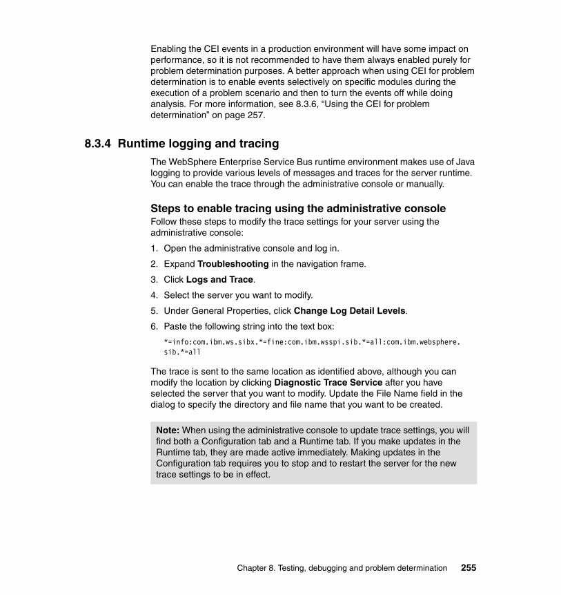
Enabling the CEI events in a production environment will have some impact on performance, so it is not recommended to have them always enabled purely for problem determination purposes. A better approach when using CEI for problem determination is to enable events selectively on specific modules during the execution of a problem scenario and then to turn the events off while doing analysis. For more information, see 8.3.6, “Using the CEI for problem determination” on page 257.
8.3.4 Runtime logging and tracingThe WebSphere Enterprise Service Bus runtime environment makes use of Java logging to provide various levels of messages and traces for the server runtime. You can enable the trace through the administrative console or manually.
Steps to enable tracing using the administrative consoleFollow these steps to modify the trace settings for your server using the administrative console:
1. Open the administrative console and log in.
2. Expand Troubleshooting in the navigation frame.
3. Click Logs and Trace.
4. Select the server you want to modify.
5. Under General Properties, click Change Log Detail Levels.
6. Paste the following string into the text box:
*=info:com.ibm.ws.sibx.*=fine:com.ibm.wsspi.sib.*=all:com.ibm.websphere. sib.*=all
The trace is sent to the same location as identified above, although you can modify the location by clicking Diagnostic Trace Service after you have selected the server that you want to modify. Update the File Name field in the dialog to specify the directory and file name that you want to be created.
Note: When using the administrative console to update trace settings, you will find both a Configuration tab and a Runtime tab. If you make updates in the Runtime tab, they are made active immediately. Making updates in the Configuration tab requires you to stop and to restart the server for the new trace settings to be in effect.
Chapter 8. Testing, debugging and problem determination 255
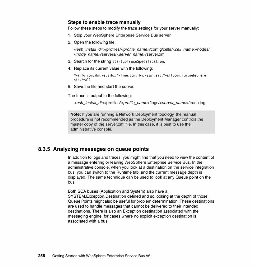
Steps to enable trace manuallyFollow these steps to modify the trace settings for your server manually:
1. Stop your WebSphere Enterprise Service Bus server.
2. Open the following file:
<esb_install_dir>/profiles/<profile_name>/config/cells/<cell_name>/nodes/<node_name>/servers/<server_name>/server.xml
3. Search for the string startupTraceSpecification.
4. Replace its current value with the following:
*=info:com.ibm.ws.sibx.*=fine:com.ibm.wsspi.sib.*=all:com.ibm.websphere.sib.*=all
5. Save the file and start the server.
The trace is output to the following:
<esb_install_dir>/profiles/<profile_name>/logs/<server_name>/trace.log
8.3.5 Analyzing messages on queue pointsIn addition to logs and traces, you might find that you need to view the content of a message entering or leaving WebSphere Enterprise Service Bus. In the administrative console, when you look at a destination on the service integration bus, you can switch to the Runtime tab, and the current message depth is displayed. The same technique can be used to look at any Queue point on the bus.
Both SCA buses (Application and System) also have a SYSTEM.Exception.Destination defined and so looking at the depth of those Queue Points might also be useful for problem determination. These destinations are used to handle messages that cannot be delivered to their intended destinations. There is also an Exception destination associated with the messaging engine, for cases where no explicit exception destination is associated with a bus.
Note: If you are running a Network Deployment topology, the manual procedure is not recommended as the Deployment Manager controls the master copy of the server.xml file. In this case, it is best to use the administrative console.
256 Getting Started with WebSphere Enterprise Service Bus V6
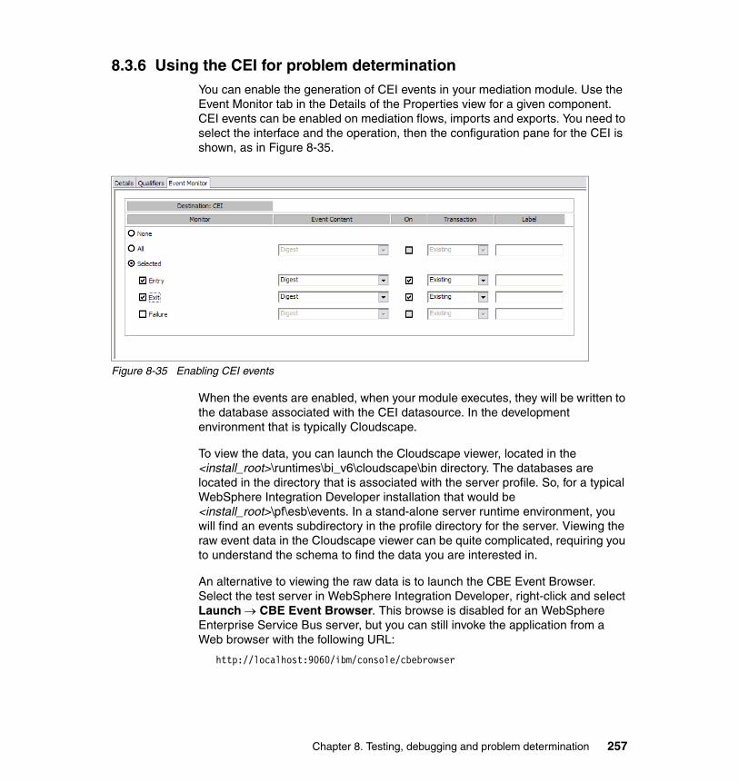
8.3.6 Using the CEI for problem determinationYou can enable the generation of CEI events in your mediation module. Use the Event Monitor tab in the Details of the Properties view for a given component. CEI events can be enabled on mediation flows, imports and exports. You need to select the interface and the operation, then the configuration pane for the CEI is shown, as in Figure 8-35.
Figure 8-35 Enabling CEI events
When the events are enabled, when your module executes, they will be written to the database associated with the CEI datasource. In the development environment that is typically Cloudscape.
To view the data, you can launch the Cloudscape viewer, located in the <install_root>\runtimes\bi_v6\cloudscape\bin directory. The databases are located in the directory that is associated with the server profile. So, for a typical WebSphere Integration Developer installation that would be <install_root>\pf\esb\events. In a stand-alone server runtime environment, you will find an events subdirectory in the profile directory for the server. Viewing the raw event data in the Cloudscape viewer can be quite complicated, requiring you to understand the schema to find the data you are interested in.
An alternative to viewing the raw data is to launch the CBE Event Browser. Select the test server in WebSphere Integration Developer, right-click and select Launch → CBE Event Browser. This browse is disabled for an WebSphere Enterprise Service Bus server, but you can still invoke the application from a Web browser with the following URL:
http://localhost:9060/ibm/console/cbebrowser
Chapter 8. Testing, debugging and problem determination 257
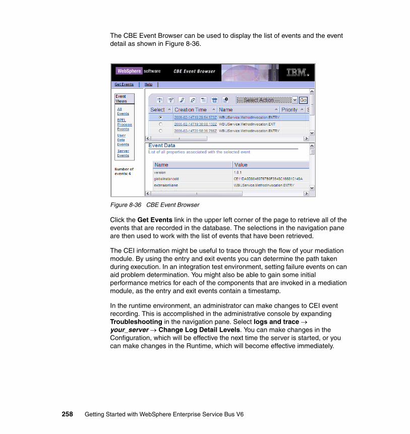
The CBE Event Browser can be used to display the list of events and the event detail as shown in Figure 8-36.
Figure 8-36 CBE Event Browser
Click the Get Events link in the upper left corner of the page to retrieve all of the events that are recorded in the database. The selections in the navigation pane are then used to work with the list of events that have been retrieved.
The CEI information might be useful to trace through the flow of your mediation module. By using the entry and exit events you can determine the path taken during execution. In an integration test environment, setting failure events on can aid problem determination. You might also be able to gain some initial performance metrics for each of the components that are invoked in a mediation module, as the entry and exit events contain a timestamp.
In the runtime environment, an administrator can make changes to CEI event recording. This is accomplished in the administrative console by expanding Troubleshooting in the navigation pane. Select logs and trace → your_server → Change Log Detail Levels. You can make changes in the Configuration, which will be effective the next time the server is started, or you can make changes in the Runtime, which will become effective immediately.
258 Getting Started with WebSphere Enterprise Service Bus V6
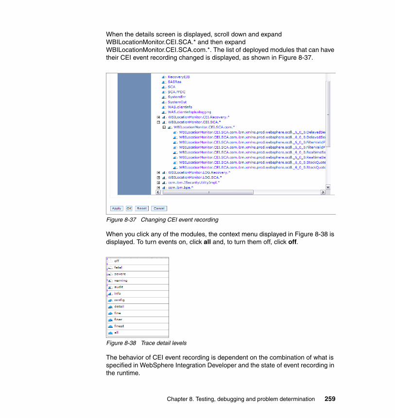
When the details screen is displayed, scroll down and expand WBILocationMonitor.CEI.SCA.* and then expand WBILocationMonitor.CEI.SCA.com.*. The list of deployed modules that can have their CEI event recording changed is displayed, as shown in Figure 8-37.
Figure 8-37 Changing CEI event recording
When you click any of the modules, the context menu displayed in Figure 8-38 is displayed. To turn events on, click all and, to turn them off, click off.
Figure 8-38 Trace detail levels
The behavior of CEI event recording is dependent on the combination of what is specified in WebSphere Integration Developer and the state of event recording in the runtime.
Chapter 8. Testing, debugging and problem determination 259
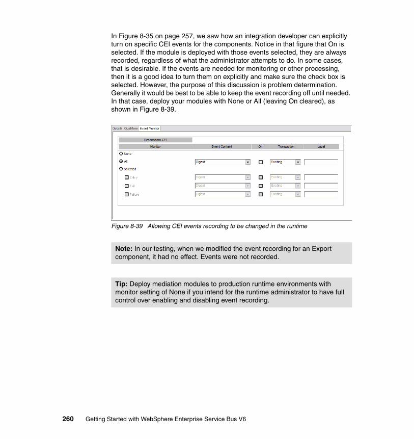
In Figure 8-35 on page 257, we saw how an integration developer can explicitly turn on specific CEI events for the components. Notice in that figure that On is selected. If the module is deployed with those events selected, they are always recorded, regardless of what the administrator attempts to do. In some cases, that is desirable. If the events are needed for monitoring or other processing, then it is a good idea to turn them on explicitly and make sure the check box is selected. However, the purpose of this discussion is problem determination. Generally it would be best to be able to keep the event recording off until needed. In that case, deploy your modules with None or All (leaving On cleared), as shown in Figure 8-39.
Figure 8-39 Allowing CEI events recording to be changed in the runtime
Note: In our testing, when we modified the event recording for an Export component, it had no effect. Events were not recorded.
Tip: Deploy mediation modules to production runtime environments with monitor setting of None if you intend for the runtime administrator to have full control over enabling and disabling event recording.
260 Getting Started with WebSphere Enterprise Service Bus V6
Chapter 9. Administering WebSphere Enterprise Service Bus
This chapter discusses the administration aspects of WebSphere Enterprise Service Bus V6.0.1.
WebSphere Enterprise Service Bus V6.0.1 is based on the WebSphere Application Server platform foundation and is built on top of WebSphere Application Server Network Deployment. WebSphere Enterprise Service Bus inherits all of the administration functionality from WebSphere Application Server Network Deployment, including clustering, fail-over, and security. In addition, WebSphere Enterprise Service Bus introduces new administration tasks to deploy, administer, and manage mediation modules and service integration applications.
This chapter focuses only on the new administration tasks that are introduced in WebSphere Enterprise Service Bus. For information about administration tasks that are common to WebSphere Application Server Network Deployment and high availability, consult the following redbooks:
� WebSphere Application Server V6 System Management & Configuration Handbook, SG24-6451
� WebSphere Application Server Network Deployment V6: High Availability Solutions, SG24-6688
9
© Copyright IBM Corp. 2006. All rights reserved. 261
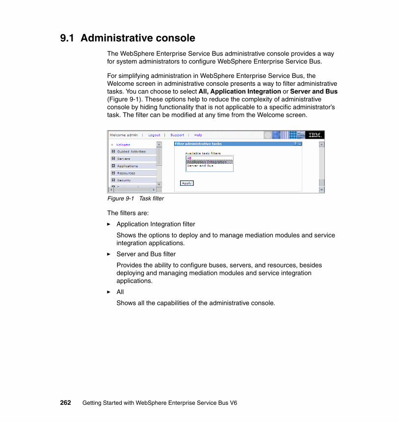
9.1 Administrative consoleThe WebSphere Enterprise Service Bus administrative console provides a way for system administrators to configure WebSphere Enterprise Service Bus.
For simplifying administration in WebSphere Enterprise Service Bus, the Welcome screen in administrative console presents a way to filter administrative tasks. You can choose to select All, Application Integration or Server and Bus (Figure 9-1). These options help to reduce the complexity of administrative console by hiding functionality that is not applicable to a specific administrator’s task. The filter can be modified at any time from the Welcome screen.
Figure 9-1 Task filter
The filters are:
� Application Integration filter
Shows the options to deploy and to manage mediation modules and service integration applications.
� Server and Bus filter
Provides the ability to configure buses, servers, and resources, besides deploying and managing mediation modules and service integration applications.
� All
Shows all the capabilities of the administrative console.
262 Getting Started with WebSphere Enterprise Service Bus V6
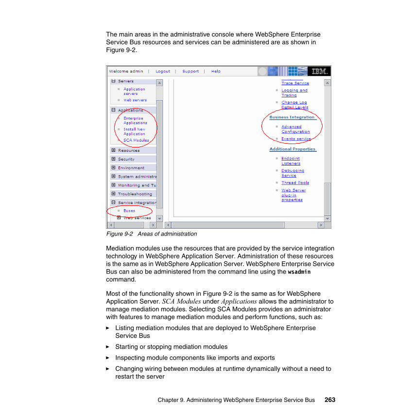
The main areas in the administrative console where WebSphere Enterprise Service Bus resources and services can be administered are as shown in Figure 9-2.
Figure 9-2 Areas of administration
Mediation modules use the resources that are provided by the service integration technology in WebSphere Application Server. Administration of these resources is the same as in WebSphere Application Server. WebSphere Enterprise Service Bus can also be administered from the command line using the wsadmin command.
Most of the functionality shown in Figure 9-2 is the same as for WebSphere Application Server. SCA Modules under Applications allows the administrator to manage mediation modules. Selecting SCA Modules provides an administrator with features to manage mediation modules and perform functions, such as:
� Listing mediation modules that are deployed to WebSphere Enterprise Service Bus
� Starting or stopping mediation modules
� Inspecting module components like imports and exports
� Changing wiring between modules at runtime dynamically without a need to restart the server
Chapter 9. Administering WebSphere Enterprise Service Bus 263
These features are discussed further in 9.3, “Mediation module administration” on page 271.
Selecting Advanced Configuration under Business Integration allows the administrator to configure the server to host SCA applications. For more information, see 5.4.3, “Final configuration steps” on page 102.
9.2 Deploying mediation modulesDepending on the mediation module, an administrator might have some tasks to complete before deploying the module to ensure a successful deployment and a working application. This section discusses some of the common tasks to consider before a deployment.
9.2.1 Configuring Web service bindingsIf the mediation module being deployed is using a Web service binding on an Import, an administrator must be ensure the Web service binding is using the correct host name and port number on which the Web service provider has been bound.
While a mismatch in the port will not affect the deployment, it will lead to failure of the service integration solution. It is possible to change the Web service binding at runtime after the mediation module is deployed using the administrative console (Applications → Enterprise Applications → application_instance → EJB modules → module_instance → Web services client bindings) as shown in Figure 9-3.
264 Getting Started with WebSphere Enterprise Service Bus V6
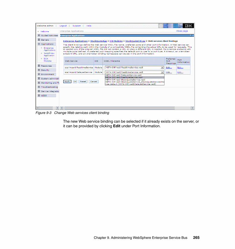
Figure 9-3 Change Web services client binding
The new Web service binding can be selected if it already exists on the server, or it can be provided by clicking Edit under Port Information.
Chapter 9. Administering WebSphere Enterprise Service Bus 265
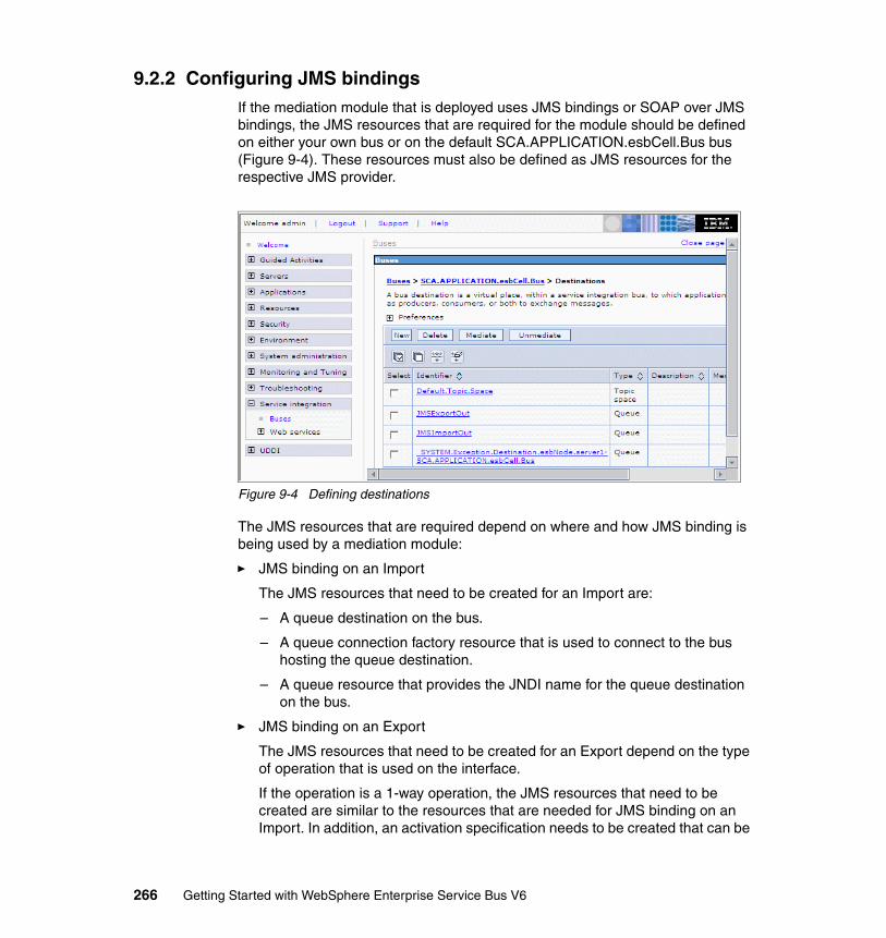
9.2.2 Configuring JMS bindingsIf the mediation module that is deployed uses JMS bindings or SOAP over JMS bindings, the JMS resources that are required for the module should be defined on either your own bus or on the default SCA.APPLICATION.esbCell.Bus bus (Figure 9-4). These resources must also be defined as JMS resources for the respective JMS provider.
Figure 9-4 Defining destinations
The JMS resources that are required depend on where and how JMS binding is being used by a mediation module:
� JMS binding on an Import
The JMS resources that need to be created for an Import are:
– A queue destination on the bus.
– A queue connection factory resource that is used to connect to the bus hosting the queue destination.
– A queue resource that provides the JNDI name for the queue destination on the bus.
� JMS binding on an Export
The JMS resources that need to be created for an Export depend on the type of operation that is used on the interface.
If the operation is a 1-way operation, the JMS resources that need to be created are similar to the resources that are needed for JMS binding on an Import. In addition, an activation specification needs to be created that can be
266 Getting Started with WebSphere Enterprise Service Bus V6
used by the mediation module to register the queue with a message listener in the mediation module.
If the operation is a request response operation, the following resources are required:
– A queue destination for the request.
– A queue destination for the response.
– JNDI resources for the queue connection factory resource that is used to connect to the bus hosting these queue destinations, and the queue resources that provides the JNDI name for the request and response queue destination on the bus.
In addition to these resources, you also have to create an activation specification that is used by the mediation module to register the input queue with the message listener in the mediation module.
� SOAP over JMS binding
The JMS resources needed for this type of binding are similar to the resources needed for a JMS binding on an Import.
9.2.3 Methods to deploy service mediation modulesDepending on the environment, a mediation module can be deployed in one of the following ways:
� From WebSphere Integration Developer by right-clicking a server in the Servers view and selecting Add and remove projects.
� By exporting a deployable EAR file from WebSphere Integration Developer and installing it into WebSphere Enterprise Service Bus using the administrative console.
� By exporting a deployable EAR file from WebSphere Integration Developer and installing it into WebSphere Enterprise Service Bus using the wsadmin command line utility.
� By exporting a deployable EAR file from WebSphere Integration Developer and installing it into WebSphere Enterprise Service Bus using the serviceDeploy command line utility.
Chapter 9. Administering WebSphere Enterprise Service Bus 267
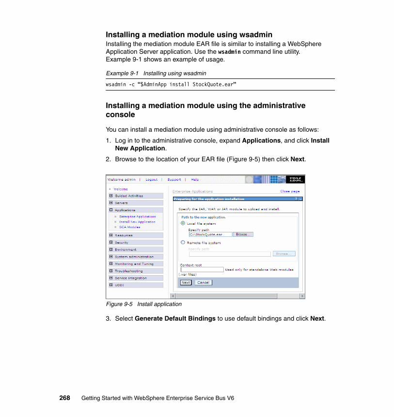
Installing a mediation module using wsadminInstalling the mediation module EAR file is similar to installing a WebSphere Application Server application. Use the wsadmin command line utility. Example 9-1 shows an example of usage.
Example 9-1 Installing using wsadmin
wsadmin -c “$AdminApp install StockQuote.ear”
Installing a mediation module using the administrative console
You can install a mediation module using administrative console as follows:
1. Log in to the administrative console, expand Applications, and click Install New Application.
2. Browse to the location of your EAR file (Figure 9-5) then click Next.
Figure 9-5 Install application
3. Select Generate Default Bindings to use default bindings and click Next.
268 Getting Started with WebSphere Enterprise Service Bus V6
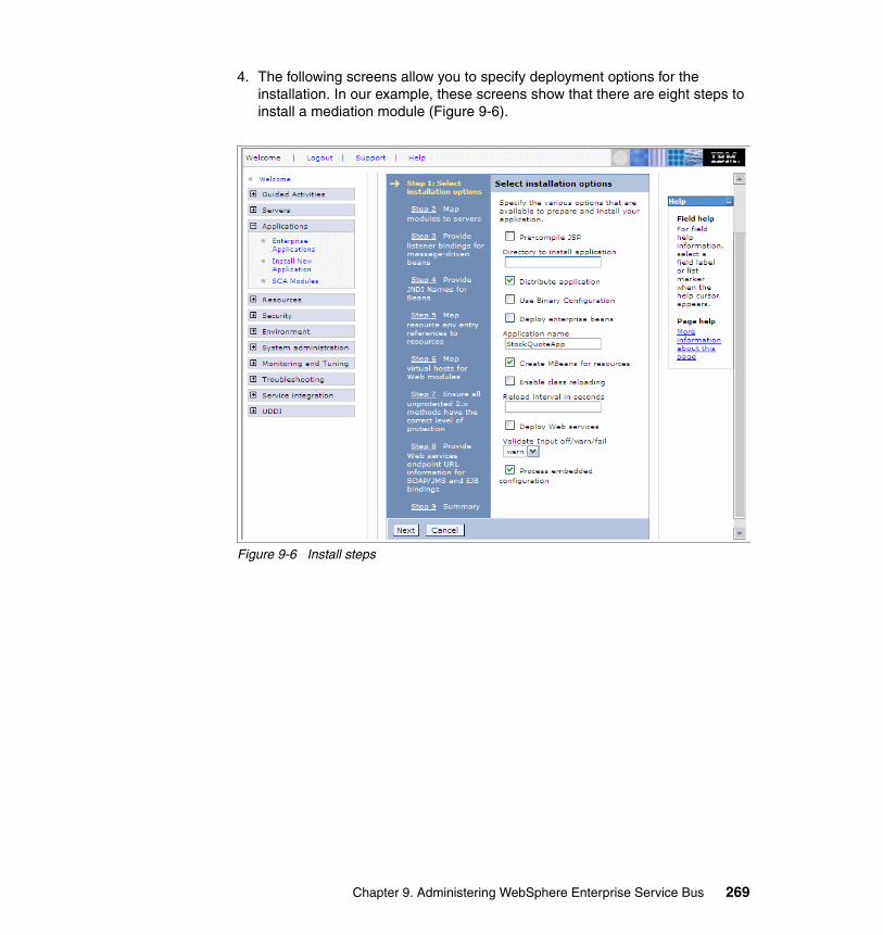
4. The following screens allow you to specify deployment options for the installation. In our example, these screens show that there are eight steps to install a mediation module (Figure 9-6).
Figure 9-6 Install steps
Chapter 9. Administering WebSphere Enterprise Service Bus 269
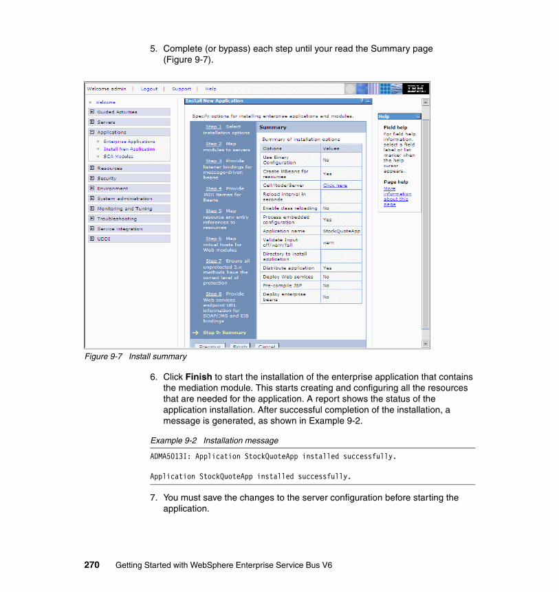
5. Complete (or bypass) each step until your read the Summary page (Figure 9-7).
Figure 9-7 Install summary
6. Click Finish to start the installation of the enterprise application that contains the mediation module. This starts creating and configuring all the resources that are needed for the application. A report shows the status of the application installation. After successful completion of the installation, a message is generated, as shown in Example 9-2.
Example 9-2 Installation message
ADMA5013I: Application StockQuoteApp installed successfully.
Application StockQuoteApp installed successfully.
7. You must save the changes to the server configuration before starting the application.
270 Getting Started with WebSphere Enterprise Service Bus V6
Installing a mediation module using service deployWebSphere Enterprise Service Bus provides a command line utility called serviceDeploy that you can use to build deployable mediation modules from zipped or JAR files that contain service components. You can export a mediation module from WebSphere Integration Developer to be used later by the serviceDeploy command for generation of deployable EAR file.
If a mediation module is exported from WebSphere Integration Developer as a zipped file or a JAR file, it will not contain any deployable code. It will contain only files that describe the module and its components.
Running serviceDeploy generates an installable EAR file that contains all the deployable code that is required for the module to run as a service application on WebSphere Enterprise Service Bus. An example of using serviceDeploy is shown in Example 9-3.
Example 9-3 Using Service Deploy
serviceDeploy.bat c:\temp\MyModule.zip -outputApplication MyModule.ear
The serviceDeploy utility is used commonly by development teams who use a version control system. After developers check in their mediation module projects into a source code repository, the modules can be extracted and built into installable EAR files using serviceDeploy. This method can be useful for deploying the application in a system test environment or a production environment. Using this method ensures that the runtime code is not checked in but that it is generated when required.
9.3 Mediation module administrationWebSphere Enterprise Service Bus allows users to view deployed mediation modules in the administrative console or using the command line. Details of the components inside that module, such as imports and exports, can also be displayed. SCA bindings that are defined in a mediation module import can be modified at runtime to change the flow of messages through the bus.
Chapter 9. Administering WebSphere Enterprise Service Bus 271
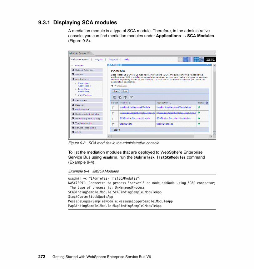
9.3.1 Displaying SCA modulesA mediation module is a type of SCA module. Therefore, in the administrative console, you can find mediation modules under Applications → SCA Modules (Figure 9-8).
Figure 9-8 SCA modules in the administrative console
To list the mediation modules that are deployed to WebSphere Enterprise Service Bus using wsadmin, run the $AdminTask listSCAModules command (Example 9-4).
Example 9-4 listSCAModules
wsadmin -c “$AdminTask listSCAModules”WASX7209I: Connected to process "server1" on node esbNode using SOAP connector; The type of process is: UnManagedProcessSCABindingSample1Module:SCABindingSample1ModuleAppStockQuote:StockQuoteAppMessageLoggerSample1Module:MessageLoggerSample1ModuleAppMapBindingSample1Module:MapBindingSample1ModuleApp
272 Getting Started with WebSphere Enterprise Service Bus V6
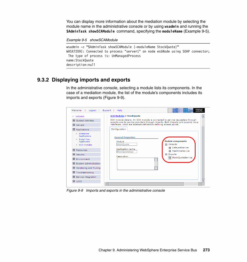
You can display more information about the mediation module by selecting the module name in the administrative console or by using wsadmin and running the $AdminTask showSCAModule command, specifying the moduleName (Example 9-5).
Example 9-5 showSCAModule
wsadmin -c “$AdminTask showSCAModule {-moduleName StockQuote}”WASX7209I: Connected to process "server1" on node esbNode using SOAP connector; The type of process is: UnManagedProcessname:StockQuotedescription:null
9.3.2 Displaying imports and exportsIn the administrative console, selecting a module lists its components. In the case of a mediation module, the list of the module’s components includes its imports and exports (Figure 9-9).
Figure 9-9 Imports and exports in the administrative console
Chapter 9. Administering WebSphere Enterprise Service Bus 273

To display a mediation modules imports using wsadmin, run the $AdminTask listSCAImports command, specifying the moduleName (Example 9-6).
Example 9-6 listSCAImports
wsadmin -c “$AdminTask listSCAImports {-moduleName StockQuote}”WASX7209I: Connected to process "server1" on node esbNode using SOAP connector; The type of process is: UnManagedProcessDelayedServiceRealtimeService
To display a mediation modules exports using wsadmin, run the $AdminTask listSCAExports command, specifying the moduleName (Example 9-7).
Example 9-7 listSCAExports
wsadmin -c “$AdminTask listSCAExports {-moduleName StockQuote}”WASX7209I: Connected to process "server1" on node esbNode using SOAP connector; The type of process is: UnManagedProcessStockQuoteService
To display more information about an import, run the $AdminTask showSCAImport command, specifying the module name and the import (Example 9-8).
Example 9-8 showSCAImport
wsadmin -c “$AdminTask showSCAImport {-moduleName StockQuote -import DelayedService}”WASX7209I: Connected to process "server1" on node esbNode using SOAP connector; The type of process is: UnManagedProcessimport:name=DelayedService,description=nullinterface:type=WSDLPortType,portType=ns1:DelayedServicePortType
To display more information about an export, run the $AdminTask showSCAExport command, specifying the module name and the export (Example 9-9).
Example 9-9 showSCAExport
wsadmin -c “$AdminTask showSCAExport {-moduleName StockQuote -export StockQuoteService}”WASX7209I: Connected to process "server1" on node esbNode using SOAP connector; The type of process is: UnManagedProcessexport:name=StockQuoteService,description=nullinterface:type=WSDLPortType,portType=ns1:StockQuoteService
274 Getting Started with WebSphere Enterprise Service Bus V6
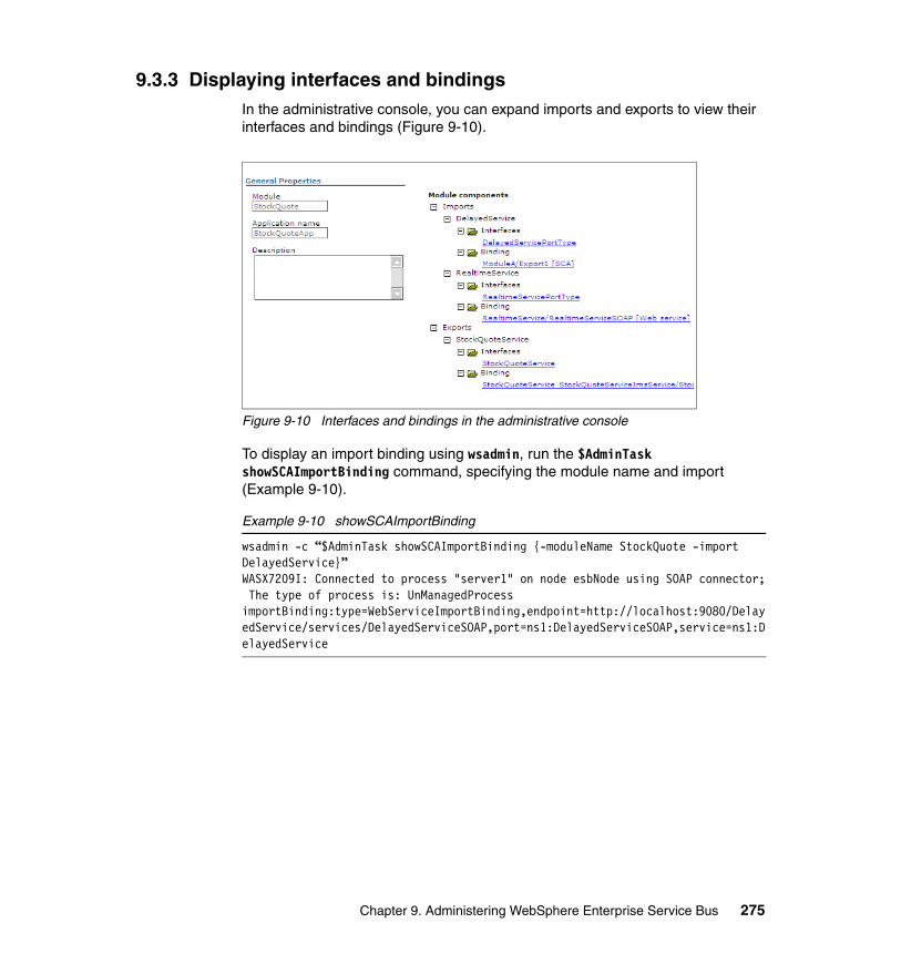
9.3.3 Displaying interfaces and bindingsIn the administrative console, you can expand imports and exports to view their interfaces and bindings (Figure 9-10).
Figure 9-10 Interfaces and bindings in the administrative console
To display an import binding using wsadmin, run the $AdminTask showSCAImportBinding command, specifying the module name and import (Example 9-10).
Example 9-10 showSCAImportBinding
wsadmin -c “$AdminTask showSCAImportBinding {-moduleName StockQuote -import DelayedService}”WASX7209I: Connected to process "server1" on node esbNode using SOAP connector; The type of process is: UnManagedProcessimportBinding:type=WebServiceImportBinding,endpoint=http://localhost:9080/DelayedService/services/DelayedServiceSOAP,port=ns1:DelayedServiceSOAP,service=ns1:DelayedService
Chapter 9. Administering WebSphere Enterprise Service Bus 275
To display an export binding using wsadmin, run the $AdminTask showSCAExportBinding command, specifying the module name and export (Example 9-11).
Example 9-11 showSCAExportBinding
wsadmin - c “$AdminTask showSCAExportBinding {-moduleName StockQuote -export StockQuoteService}”WASX7209I: Connected to process "server1" on node esbNode using SOAP connector; The type of process is: UnManagedProcessexportBinding:type=WebServiceExportBinding,port=_:StockQuoteService_StockQuoteServiceJmsPort,service=_:StockQuoteService_StockQuoteServiceJmsService
9.3.4 Changing bindingsUsing the administrative console or wsadmin, it is possible to modify a module’s SCA import bindings, giving the administrator the ability to change a deployed flow. This feature effectively allows a flow of mediation modules to be rewired at runtime, thus eliminating the need for a developer to use WebSphere Integration Developer to modify, export, and redeploy and does not require a server restart.
To modify SCA binding using the administrative console:
1. Select Applications and click SCA Modules → <module_instance>.
2. Select Imports → <import> → Binding and click the SCA binding that you want to modify.
Tip: The binding type is shown in square brackets after the name of the binding.
276 Getting Started with WebSphere Enterprise Service Bus V6
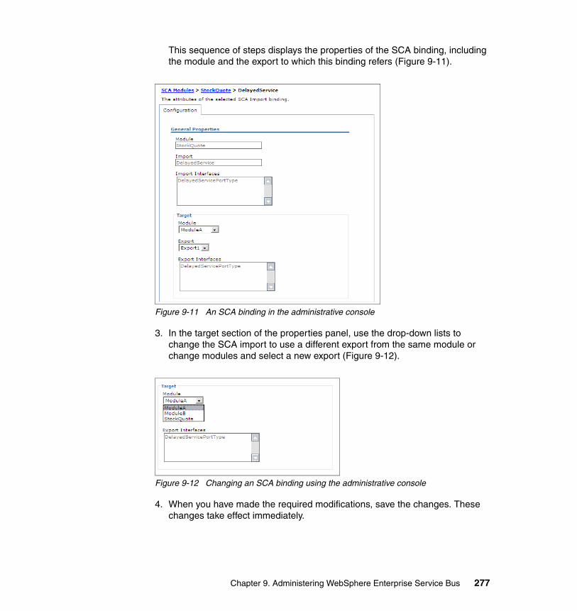
This sequence of steps displays the properties of the SCA binding, including the module and the export to which this binding refers (Figure 9-11).
Figure 9-11 An SCA binding in the administrative console
3. In the target section of the properties panel, use the drop-down lists to change the SCA import to use a different export from the same module or change modules and select a new export (Figure 9-12).
Figure 9-12 Changing an SCA binding using the administrative console
4. When you have made the required modifications, save the changes. These changes take effect immediately.
Chapter 9. Administering WebSphere Enterprise Service Bus 277

To change an SCA binding using wsadmin, run the $AdminTask modifySCAImportSCABinding command, specifying the moduleName, import, targetModule and targetExport (Example 9-12).
Example 9-12 modifySCAImportSCABinding
wsadmin -c “$AdminTask modifySCAImportSCABinding {-moduleName StockQuote -import StockQuoteService -targetModule ModuleB -targetExport Export1}”
Tip: It is not currently possible to modify binding types other than SCA using this method.
278 Getting Started with WebSphere Enterprise Service Bus V6
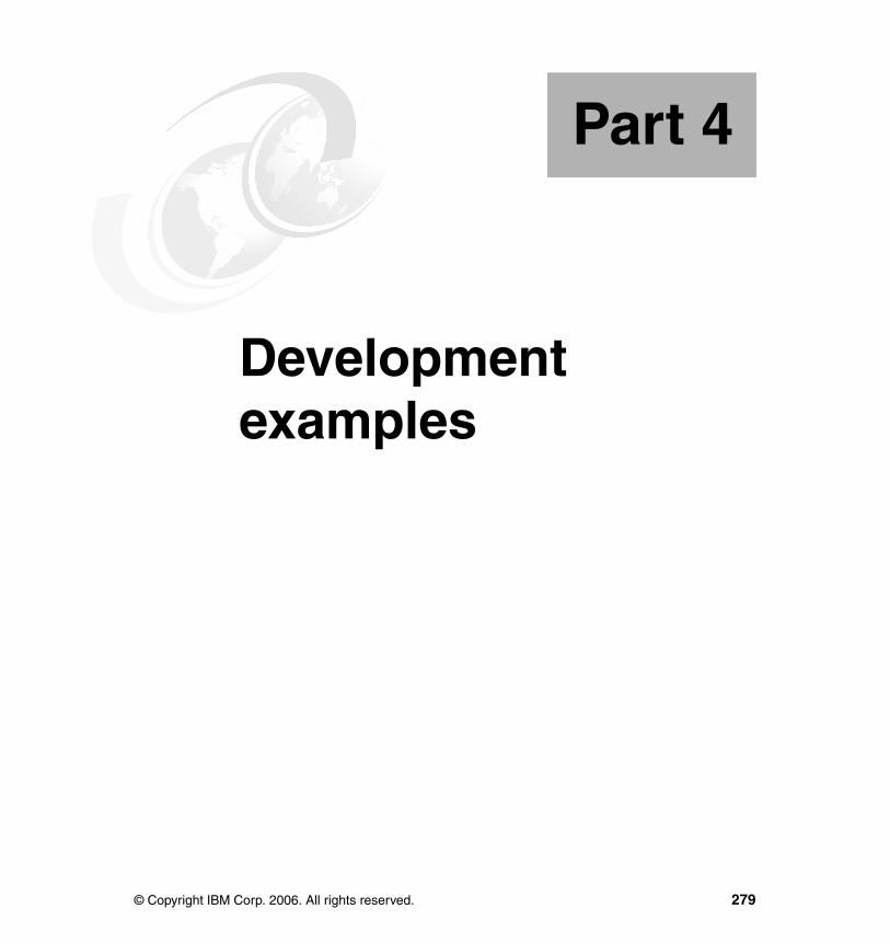
Part 4 Development examples
Part 4
© Copyright IBM Corp. 2006. All rights reserved. 279

280 Getting Started with WebSphere Enterprise Service Bus V6
Chapter 10. Preparing for the development examples
This chapter describes the steps necessary to prepare your workspace for the development examples that are described in the following chapters:
� Chapter 11, “Developing integration logic using mediation modules” on page 289
� Chapter 12, “Developing mediation logic using mediation primitives” on page 381
� Chapter 13, “Configuring modules to provide quality of service” on page 455
You should complete this chapter before attempting any of the development samples included in this redbook. This chapter assumes that you have installed WebSphere Integration Developer V6.0.1.
10
© Copyright IBM Corp. 2006. All rights reserved. 281
10.1 An overview of the development examplesPart 3 of this redbook describes a number of development examples, each of which provides step-by-step instructions that explain how to implement specific functions within WebSphere Enterprise Service Bus.
The development examples are grouped logically into three sections:
� Developing mediation logic using mediation primitives
Describes how to use the mediation primitives features of WebSphere Enterprise Service Bus to build mediation flows. Describes each mediation primitive and provides individual step-by-step instructions.
Chapter 12, “Developing mediation logic using mediation primitives” on page 381 includes these development examples.
� Developing integration logic using mediation modules
Describes how to import services into an ESB, expose services on the ESB to clients and how to map services on an ESB. Provides step-by-step instructions.
Chapter 11, “Developing integration logic using mediation modules” on page 289 includes these development examples.
� Configuring modules that provide quality of service
Provides step-by-step instructions for configuring quality of service settings, including CEI events, security, and transactions.
Chapter 13, “Configuring modules to provide quality of service” on page 455 includes these development examples.
For detailed information about how to perform basic tasks in WebSphere Integration Developer, refer to Chapter 7, “WebSphere Integration Developer key concepts and common tasks” on page 159.
282 Getting Started with WebSphere Enterprise Service Bus V6
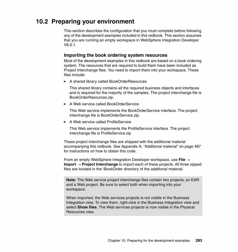
10.2 Preparing your environmentThis section describes the configuration that you must complete before following any of the development examples included in this redbook. This section assumes that you are running an empty workspace in WebSphere Integration Developer V6.0.1.
Importing the book ordering system resourcesMost of the development examples in this redbook are based on a book ordering system. The resources that are required to build them have been included as Project Interchange files. You need to import them into your workspace. These files include:
� A shared library called BookOrderResources
This shared library contains all the required business objects and interfaces and is required for the majority of the samples. The project interchange file is BookOrderResources.zip.
� A Web service called BookOrderService
This Web service implements the BookOrderService interface. The project interchange file is BookOrderService.zip.
� A Web service called ProfileService
This Web service implements the ProfileService interface. The project interchange file is ProfileService.zip
These project interchange files are shipped with the additional material accompanying this redbook. See Appendix A, “Additional material” on page 487 for instructions on how to obtain this code.
From an empty WebSphere Integration Developer workspace, use File → Import → Project Interchange to import each of these projects. All three zipped files are located in the \BookOrder directory of the additional material.
Note: The Web service project interchange files contain two projects, an EAR and a Web project. Be sure to select both when importing into your workspace.
When imported, the Web services projects is not visible in the Business Integration view. To view them, right-click in the Business Integration view and select Show files. The Web services projects is now visible in the Physical Resources view.
Chapter 10. Preparing for the development examples 283
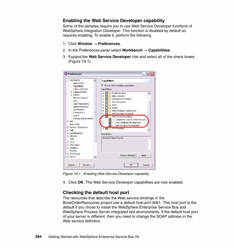
Enabling the Web Service Developer capabilitySome of the samples require you to use Web Service Developer functions of WebSphere Integration Developer. This function is disabled by default so requires enabling. To enable it, perform the following
1. Click Window → Preferences.
2. In the Preferences panel select Workbench → Capabilities.
3. Expand the Web Service Developer role and select all of the check boxes (Figure 10-1).
Figure 10-1 Enabling Web Service Developer capability
4. Click OK. The Web Service Developer capabilities are now enabled.
Checking the default host portThe resources that describe the Web service bindings in the BookOrderResources project use a default host port 9081. This host port is the default if you chose to install the WebSphere Enterprise Service Bus and WebSphere Process Server integrated test environments. If the default host port of your server is different, then you need to change the SOAP address in the Web service definition.
284 Getting Started with WebSphere Enterprise Service Bus V6

To check which default host port you are using, perform the following:
1. Start the WebSphere Enterprise Service Bus integrated test environment server.
2. Right-click the server and click Run administrative console.
3. Log in to the console.
4. Under Filter Administrative Tasks select All and click Apply (Figure 10-2).
Figure 10-2 Filter administrative tasks
5. In the navigation expand Servers and click Application servers.
6. Click server1.
7. Under Communications click Ports.
Chapter 10. Preparing for the development examples 285
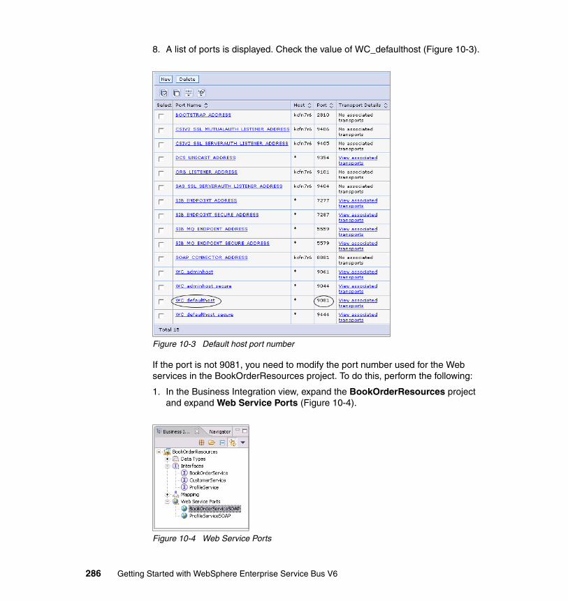
8. A list of ports is displayed. Check the value of WC_defaulthost (Figure 10-3).
Figure 10-3 Default host port number
If the port is not 9081, you need to modify the port number used for the Web services in the BookOrderResources project. To do this, perform the following:
1. In the Business Integration view, expand the BookOrderResources project and expand Web Service Ports (Figure 10-4).
Figure 10-4 Web Service Ports
286 Getting Started with WebSphere Enterprise Service Bus V6
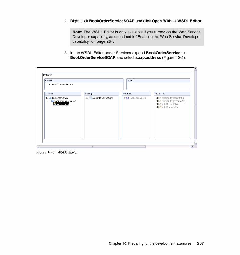
2. Right-click BookOrderServiceSOAP and click Open With → WSDL Editor.
3. In the WSDL Editor under Services expand BookOrderService → BookOrderServiceSOAP and select soap:address (Figure 10-5).
Figure 10-5 WSDL Editor
Note: The WSDL Editor is only available if you turned on the Web Service Developer capability, as described in “Enabling the Web Service Developer capability” on page 284.
Chapter 10. Preparing for the development examples 287
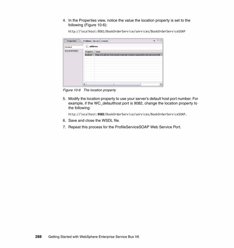
4. In the Properties view, notice the value the location property is set to the following (Figure 10-6):
http://localhost:9081/BookOrderService/services/BookOrderServiceSOAP
Figure 10-6 The location property
5. Modify the location property to use your server’s default host port number. For example, if the WC_defaulthost port is 9082, change the location property to the following:
http://localhost:9082/BookOrderService/services/BookOrderServiceSOAP.
6. Save and close the WSDL file.
7. Repeat this process for the ProfileServiceSOAP Web Service Port.
288 Getting Started with WebSphere Enterprise Service Bus V6
Chapter 11. Developing integration logic using mediation modules
This chapter provides step-by-step instructions on how to build basic integration logic in mediation modules for WebSphere Enterprise Service Bus. It contains the following three sections:
� 11.1, “Importing services” on page 290
Describes how to import and to use an existing Web service into a mediation module, how to link two mediation modules using an SCA binding, and how to bind to an Enterprise Information System such as CICS Transaction Server.
� 11.2, “Creating clients of mediation modules” on page 318
Describes how to build clients that invoke mediation modules and builds three clients with a JSP front-end: Web services, JMS, and SCA.
� 11.3, “Using services with mediation modules” on page 347
Describes how to perform protocol transformation in a mediation module by mapping bindings, how to build a mediation flow to manipulate a request and response message, and how to handle faults.
These development examples assume that you have configured your WebSphere Integration Developer workspace as described in Chapter 10, “Preparing for the development examples” on page 281. You might find it useful to refer to Chapter 7, “WebSphere Integration Developer key concepts and common tasks” on page 159 for more detailed information about how to perform specific tasks in WebSphere Integration Developer.
11
© Copyright IBM Corp. 2006. All rights reserved. 289
11.1 Importing servicesThis section introduces how to import resources into mediation module for use by an ESB. It discusses importing Web services, importing and exporting SCA modules, and importing an Enterprise Information System (EIS) such as CICS Transaction Service.
You can import each of the development examples in this section as Project Interchange files from the additional material that is supplied with this redbook in the \ImportingServices\Solutions directory.
11.1.1 BindingsBoth imports and exports require binding information, specifying the means of transport from and to the module. WebSphere Enterprise Service Bus supports the following bindings:
� SCA� Web service� EIS� JMS� EJB (import only)
We use many of the following bindings in the development examples in this redbook:
� Web service binding
The Web service binding is used in many of our samples, for example in 11.1.2, “Importing an existing Web service” on page 291 (import) and 11.3.1, “Mapping bindings” on page 348 (export).
� JMS binding
The JMS binding is used in 11.3.1, “Mapping bindings” on page 348 (import) and in 11.2.2, “JMS client” on page 325 (export).
There is no example of a JMS custom binding in this book, but you can find information about it in the following article:
http://www.ibm.com/developerworks/websphere/techjournal/0602_tost/0602_tost.html
� SCA binding
How to use SCA bindings is shown in 11.1.3, “Connect two modules using SCA binding” on page 295.
� EJB binding
There is no sample of an import with an EJB binding in this book.
290 Getting Started with WebSphere Enterprise Service Bus V6
� EIS binding
Look at 11.1.4, “EIS binding to CICS” on page 303 for an example on an import with an EIS binding.
11.1.2 Importing an existing Web serviceThis sample demonstrates how to invoke an existing Web service from a mediation module. In many cases, there will be existing Web services that you will want to make available to your ESB. Importing existing services makes them available to components that reside on the ESB.
This sample involves:
� Building a mediation module that imports an existing Web service.
� Using the Integration Test Client to send requests to the module.
The completed sample demonstrates that a book order request can be sent to a mediation module that forwards it to a Web service. The Web service returns a confirmation to the module that the book order was successful. Follow these steps:
1. Create a new mediation module.
a. In the Business Integration view, right-click and select New → Mediation Module.
b. Clear the box to create a mediation flow component.
c. Set the Module Name to ImportServiceSample1Module and click Next.
d. In the Select Required Libraries dialog check the BookOrderResources library and click Finish.
2. Open the assembly diagram for the ImportServiceSample1Module module.
Chapter 11. Developing integration logic using mediation modules 291
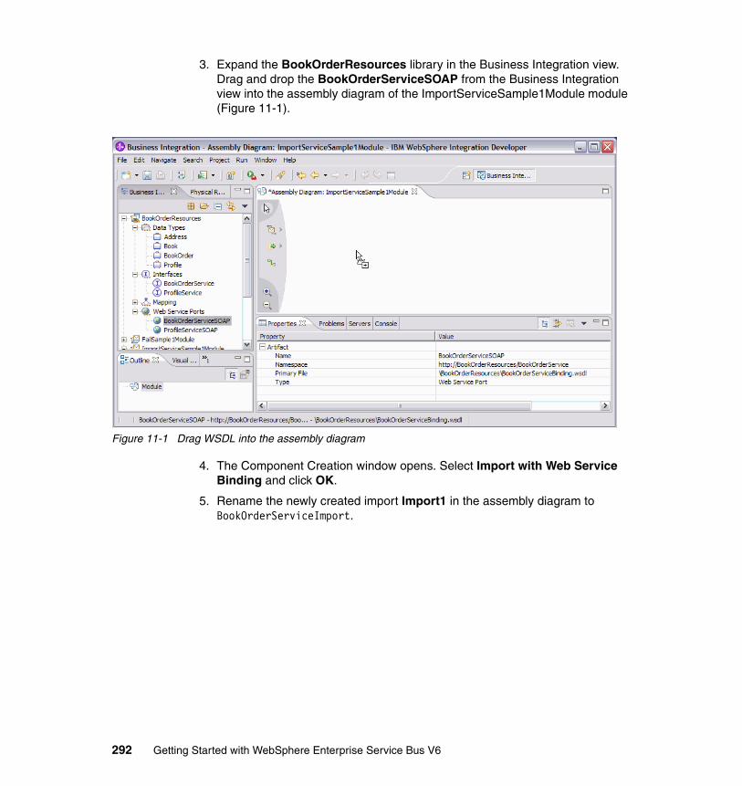
3. Expand the BookOrderResources library in the Business Integration view. Drag and drop the BookOrderServiceSOAP from the Business Integration view into the assembly diagram of the ImportServiceSample1Module module (Figure 11-1).
Figure 11-1 Drag WSDL into the assembly diagram
4. The Component Creation window opens. Select Import with Web Service Binding and click OK.
5. Rename the newly created import Import1 in the assembly diagram to BookOrderServiceImport.
292 Getting Started with WebSphere Enterprise Service Bus V6
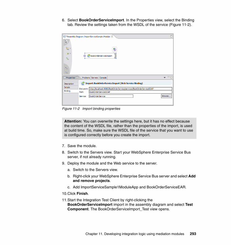
6. Select BookOrderServiceImport. In the Properties view, select the Binding tab. Review the settings taken from the WSDL of the service (Figure 11-2).
Figure 11-2 Import binding properties
7. Save the module.
8. Switch to the Servers view. Start your WebSphere Enterprise Service Bus server, if not already running.
9. Deploy the module and the Web service to the server.
a. Switch to the Servers view.
b. Right-click your WebSphere Enterprise Service Bus server and select Add and remove projects.
c. Add ImportServiceSample1ModuleApp and BookOrderServiceEAR.
10.Click Finish.
11.Start the Integration Test Client by right-clicking the BookOrderServiceImport import in the assembly diagram and select Test Component. The BookOrderServiceImport_Test view opens.
Attention: You can overwrite the settings here, but it has no effect because the content of the WSDL file, rather than the properties of the import, is used at build time. So, make sure the WSDL file of the service that you want to use is configured correctly before you create the import.
Chapter 11. Developing integration logic using mediation modules 293

12.Select the order operation and enter test data in the Initial request parameters section (Figure 11-3).
Figure 11-3 Test start settings
294 Getting Started with WebSphere Enterprise Service Bus V6
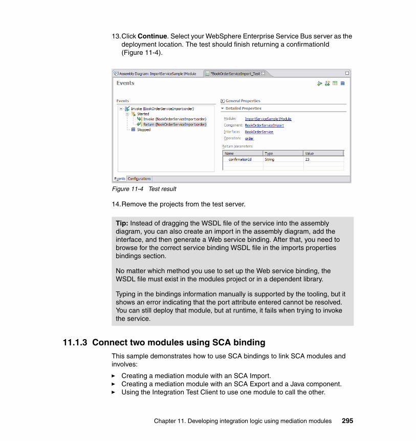
13.Click Continue. Select your WebSphere Enterprise Service Bus server as the deployment location. The test should finish returning a confirmationId (Figure 11-4).
Figure 11-4 Test result
14.Remove the projects from the test server.
11.1.3 Connect two modules using SCA bindingThis sample demonstrates how to use SCA bindings to link SCA modules and involves:
� Creating a mediation module with an SCA Import.� Creating a mediation module with an SCA Export and a Java component.� Using the Integration Test Client to use one module to call the other.
Tip: Instead of dragging the WSDL file of the service into the assembly diagram, you can also create an import in the assembly diagram, add the interface, and then generate a Web service binding. After that, you need to browse for the correct service binding WSDL file in the imports properties bindings section.
No matter which method you use to set up the Web service binding, the WSDL file must exist in the modules project or in a dependent library.
Typing in the bindings information manually is supported by the tooling, but it shows an error indicating that the port attribute entered cannot be resolved. You can still deploy that module, but at runtime, it fails when trying to invoke the service.
Chapter 11. Developing integration logic using mediation modules 295
The completed sample demonstrates how a mediation module can forward a book order request to another mediation module to handle:
1. Create a new mediation module.
a. In the Business Integration view, right-click and select New → Mediation Module.
b. Clear the box to create a mediation flow component.
c. Set the Module Name to SCABindingSample1Module and click Next.
d. In the Select Required Libraries dialog check the BookOrderResources library and click Finish.
2. Open the assembly diagram editor for SCABindingSample1Module.
3. Add an import to the assembly diagram by using .
4. Rename Import1 to SCABindingSample2ModuleImport.
5. Right-click SCABindingSample2ModuleImport and select Add Interface.
6. Select the BookOrderService interface and click OK.
7. Right-click the import and click Generate Binding → SCA Binding.
8. Save the module.
9. Create a new mediation module.
a. In the Business Integration view, right-click and select New → Mediation Module.
b. Clear the box to create a mediation flow component.
c. Set the Module Name to SCABindingSample2Module and click Next.
d. In the Select Required Libraries dialog tick the BookOrderResources library and click Finish.
10.Open the assembly diagram editor for SCABindingSample1Module.
11.Add an Export to the assembly diagram by using .
12.Rename Export1 to SCABindingSample1ModuleExport.
13.Right-click SCABindingSample1ModuleExport and select Add Interface.
14.Select the BookOrderService interface and click OK.
15.Right-click SCABindingSample1ModuleExport and select Generate Binding → SCA Binding.
16.For testing purposes, add a Java component to the assembly editor using .
17.Right-click Component1 and select Add → Interface.
18.Select the BookOrderService interface and click OK.
296 Getting Started with WebSphere Enterprise Service Bus V6
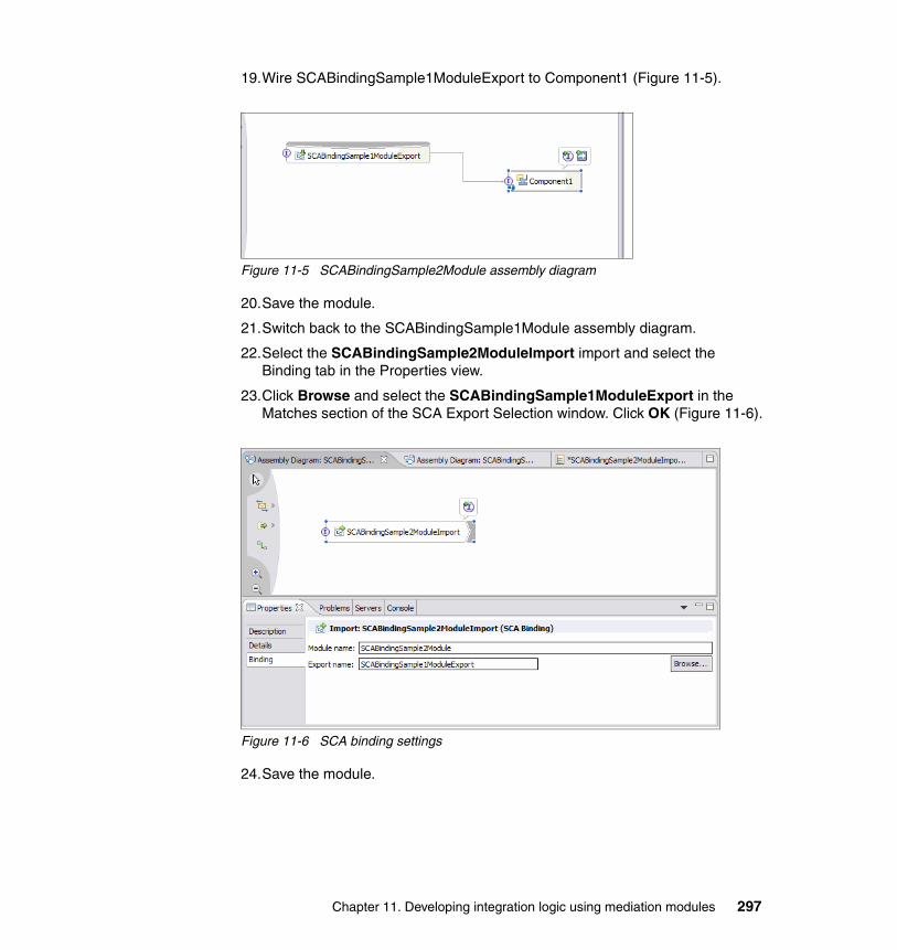
19.Wire SCABindingSample1ModuleExport to Component1 (Figure 11-5).
Figure 11-5 SCABindingSample2Module assembly diagram
20.Save the module.
21.Switch back to the SCABindingSample1Module assembly diagram.
22.Select the SCABindingSample2ModuleImport import and select the Binding tab in the Properties view.
23.Click Browse and select the SCABindingSample1ModuleExport in the Matches section of the SCA Export Selection window. Click OK (Figure 11-6).
Figure 11-6 SCA binding settings
24.Save the module.
Chapter 11. Developing integration logic using mediation modules 297
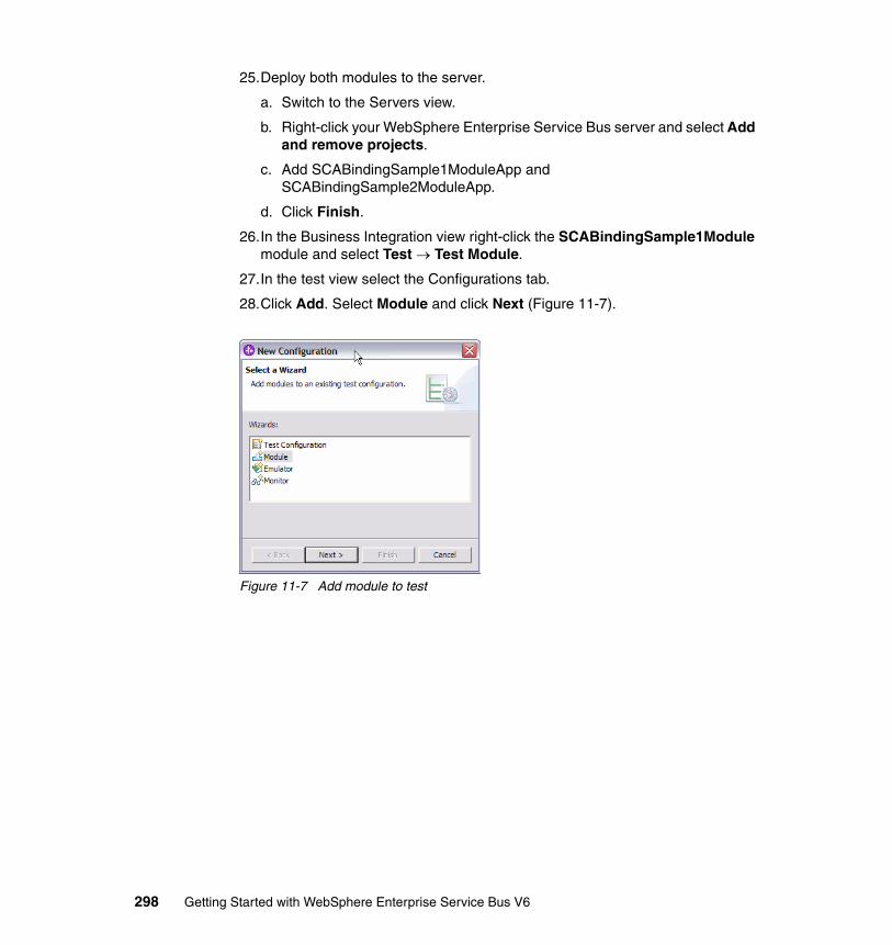
25.Deploy both modules to the server.
a. Switch to the Servers view.
b. Right-click your WebSphere Enterprise Service Bus server and select Add and remove projects.
c. Add SCABindingSample1ModuleApp and SCABindingSample2ModuleApp.
d. Click Finish.
26.In the Business Integration view right-click the SCABindingSample1Module module and select Test → Test Module.
27.In the test view select the Configurations tab.
28.Click Add. Select Module and click Next (Figure 11-7).
Figure 11-7 Add module to test
298 Getting Started with WebSphere Enterprise Service Bus V6
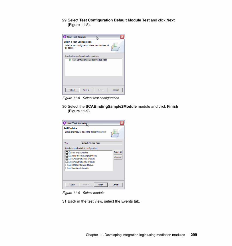
29.Select Test Configuration Default Module Test and click Next (Figure 11-8).
Figure 11-8 Select test configuration
30.Select the SCABindingSample2Module module and click Finish (Figure 11-9).
Figure 11-9 Select module
31.Back in the test view, select the Events tab.
Chapter 11. Developing integration logic using mediation modules 299
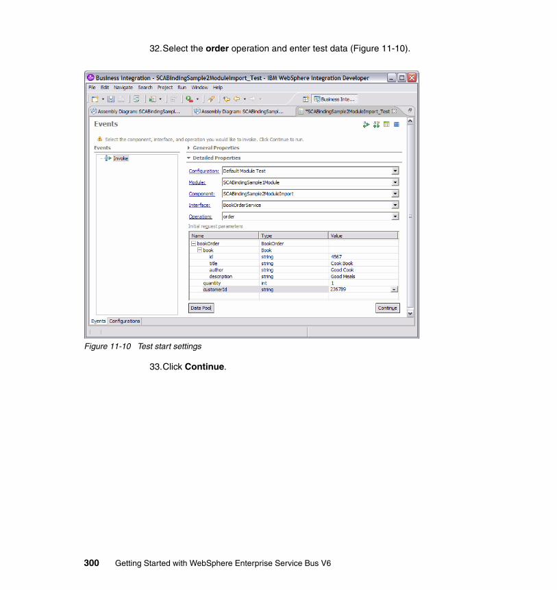
32.Select the order operation and enter test data (Figure 11-10).
Figure 11-10 Test start settings
33.Click Continue.
300 Getting Started with WebSphere Enterprise Service Bus V6
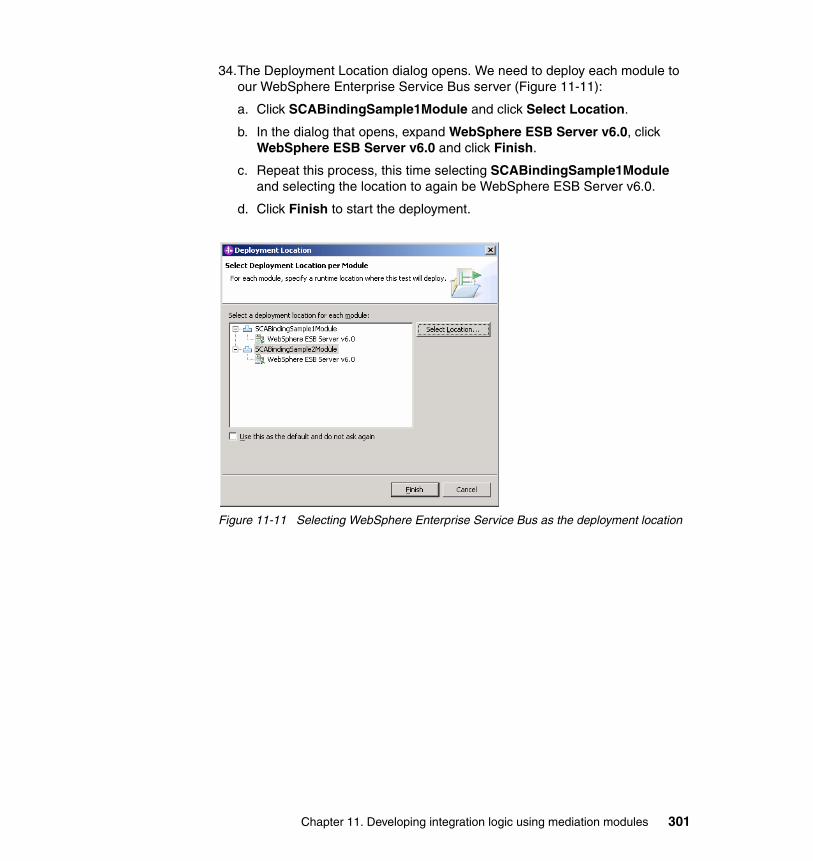
34.The Deployment Location dialog opens. We need to deploy each module to our WebSphere Enterprise Service Bus server (Figure 11-11):
a. Click SCABindingSample1Module and click Select Location.
b. In the dialog that opens, expand WebSphere ESB Server v6.0, click WebSphere ESB Server v6.0 and click Finish.
c. Repeat this process, this time selecting SCABindingSample1Module and selecting the location to again be WebSphere ESB Server v6.0.
d. Click Finish to start the deployment.
Figure 11-11 Selecting WebSphere Enterprise Service Bus as the deployment location
Chapter 11. Developing integration logic using mediation modules 301
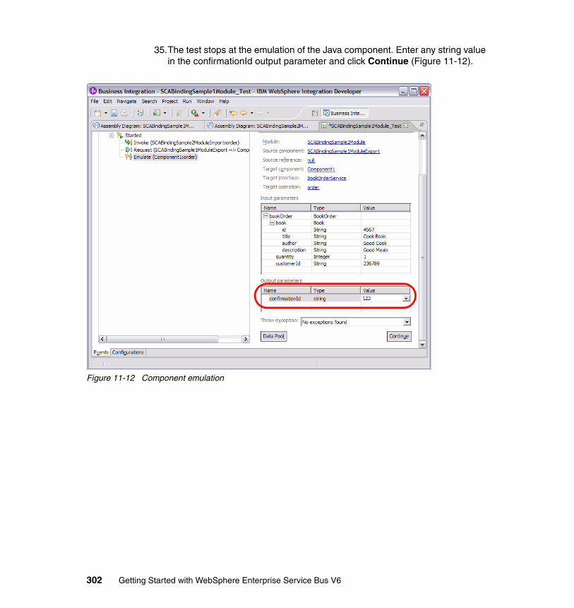
35.The test stops at the emulation of the Java component. Enter any string value in the confirmationId output parameter and click Continue (Figure 11-12).
Figure 11-12 Component emulation
302 Getting Started with WebSphere Enterprise Service Bus V6
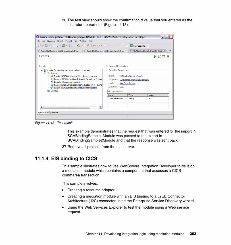
36.The test view should show the confirmationId value that you entered as the test return parameter (Figure 11-13).
Figure 11-13 Test result
This example demonstrates that the request that was entered for the import in SCABindingSample1Module was passed to the export in SCABindingSample2Module and that the response was sent back.
37.Remove all projects from the test server.
11.1.4 EIS binding to CICSThis sample illustrates how to use WebSphere Integration Developer to develop a mediation module which contains a component that accesses a CICS commarea transaction.
This sample involves:
� Creating a resource adapter.
� Creating a mediation module with an EIS binding to a J2EE Connector Architecture (J2C) connector using the Enterprise Service Discovery wizard.
� Using the Web Services Explorer to test the module using a Web service request.
Chapter 11. Developing integration logic using mediation modules 303
The completed sample demonstrates how a mediation module can use a Web service request to access a J2C interface to CICS.
For our sample, we use the EC01 transaction, which ships as a sample with the CICS Transaction Gateway. The transaction expects and returns a commarea that is defined by Example 11-1, which we use during the generation of the component.
Example 11-1 commarea example
01 DFHCOMMAREA. 02 ECIDATE PIC X(8). 02 FILLER PIC X(1). 02 ECITIME PIC X(8). 02 FILLER PIC X(3).
Follow these steps:
1. Start your WebSphere Enterprise Service Bus server.
2. Right-click the server and select Run administrative console and log in.
3. Click Resources → Resource Adapters and Install RAR.
4. Click Browse, locate your <WID_INSTALL>/Resource Adapters/cics15 directory, select the cicseci601.rar file, click Open, click Next and click OK.
5. A new resource adapter named ECIResourceAdapter appears in the list. Select it.
6. Select J2C Connection Factories under Additional Properties.
7. Click New.
8. Create a new J2C Connection Factory.
a. Set the Name to CICS01.b. Set JNDI Name to eis/CICS.c. Click OK.
9. Click the new connection factory CICS01.
10.Under Additional Properties select Custom Properties. You have to set a minimum of three properties:
a. Select ConnectionURL and set the value to the DNS name or IP address of the system running the CICS Transaction Gateway V6. Click OK.
b. Select PortNumber and set the value to port number CICS Transaction Gateway is listening on (default is 2006). Click OK.
c. Select ServerName and set the value to the name configured in the CTG for the particular CICS address space that is running the transaction you want to invoke. Click OK.
304 Getting Started with WebSphere Enterprise Service Bus V6
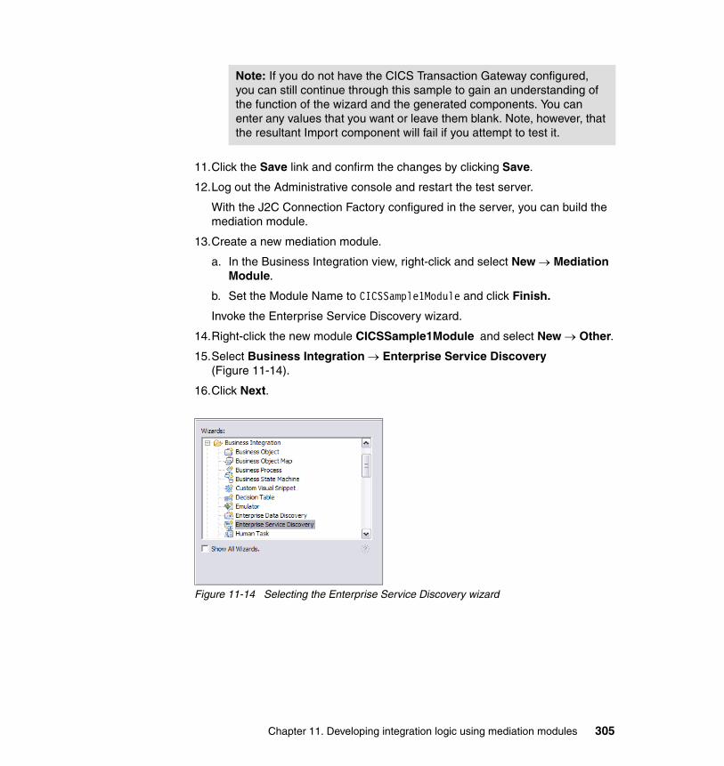
11.Click the Save link and confirm the changes by clicking Save.
12.Log out the Administrative console and restart the test server.
With the J2C Connection Factory configured in the server, you can build the mediation module.
13.Create a new mediation module.
a. In the Business Integration view, right-click and select New → Mediation Module.
b. Set the Module Name to CICSSample1Module and click Finish.
Invoke the Enterprise Service Discovery wizard.
14.Right-click the new module CICSSample1Module and select New → Other.
15.Select Business Integration → Enterprise Service Discovery (Figure 11-14).
16.Click Next.
Figure 11-14 Selecting the Enterprise Service Discovery wizard
Note: If you do not have the CICS Transaction Gateway configured, you can still continue through this sample to gain an understanding of the function of the wizard and the generated components. You can enter any values that you want or leave them blank. Note, however, that the resultant Import component will fail if you attempt to test it.
Chapter 11. Developing integration logic using mediation modules 305
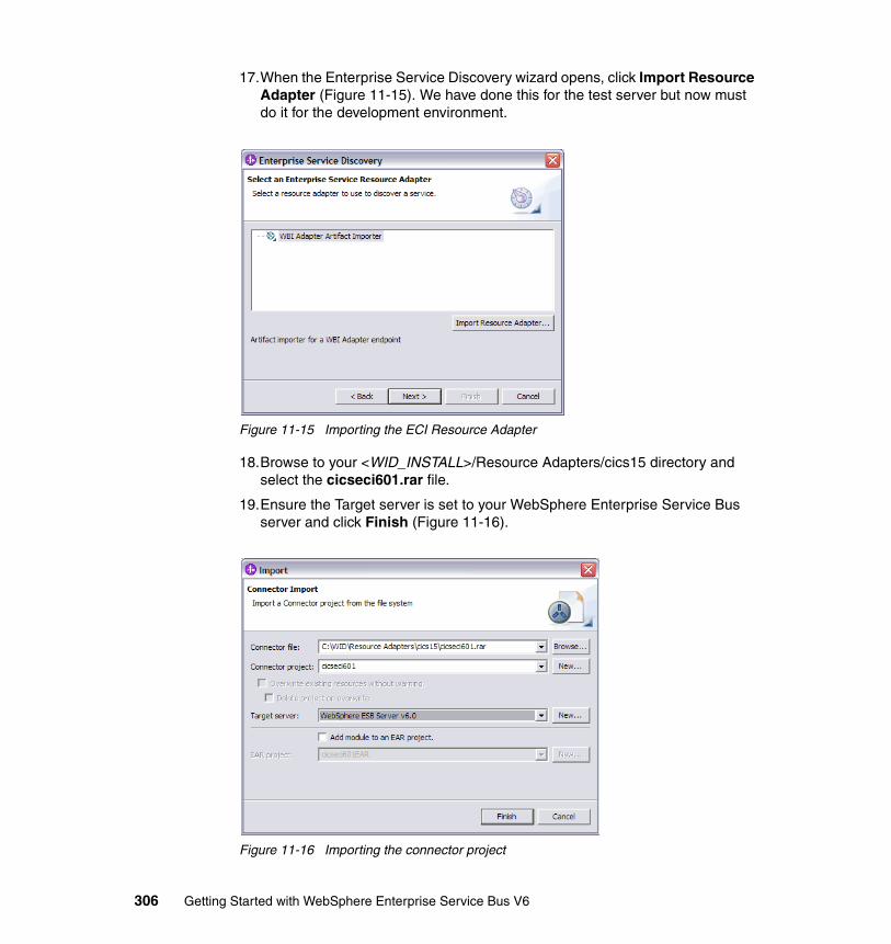
17.When the Enterprise Service Discovery wizard opens, click Import Resource Adapter (Figure 11-15). We have done this for the test server but now must do it for the development environment.
Figure 11-15 Importing the ECI Resource Adapter
18.Browse to your <WID_INSTALL>/Resource Adapters/cics15 directory and select the cicseci601.rar file.
19.Ensure the Target server is set to your WebSphere Enterprise Service Bus server and click Finish (Figure 11-16).
Figure 11-16 Importing the connector project
306 Getting Started with WebSphere Enterprise Service Bus V6
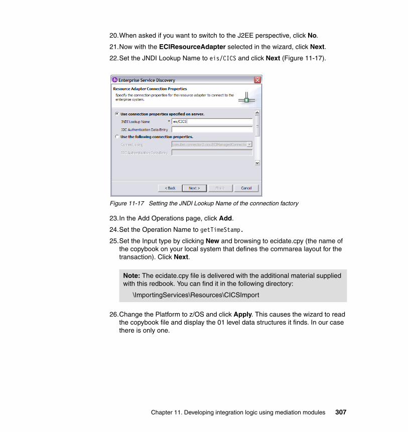
20.When asked if you want to switch to the J2EE perspective, click No.
21.Now with the ECIResourceAdapter selected in the wizard, click Next.
22.Set the JNDI Lookup Name to eis/CICS and click Next (Figure 11-17).
Figure 11-17 Setting the JNDI Lookup Name of the connection factory
23.In the Add Operations page, click Add.
24.Set the Operation Name to getTimeStamp.
25.Set the Input type by clicking New and browsing to ecidate.cpy (the name of the copybook on your local system that defines the commarea layout for the transaction). Click Next.
26.Change the Platform to z/OS and click Apply. This causes the wizard to read the copybook file and display the 01 level data structures it finds. In our case there is only one.
Note: The ecidate.cpy file is delivered with the additional material supplied with this redbook. You can find it in the following directory:
\ImportingServices\Resources\CICSImport
Chapter 11. Developing integration logic using mediation modules 307
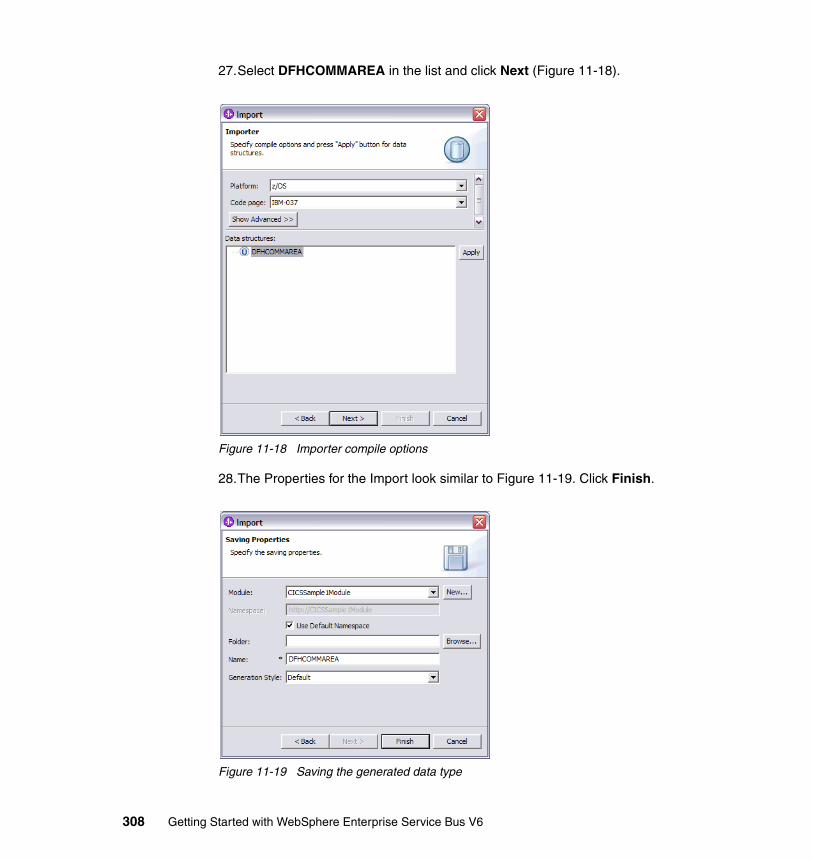
27.Select DFHCOMMAREA in the list and click Next (Figure 11-18).
Figure 11-18 Importer compile options
28.The Properties for the Import look similar to Figure 11-19. Click Finish.
Figure 11-19 Saving the generated data type
308 Getting Started with WebSphere Enterprise Service Bus V6
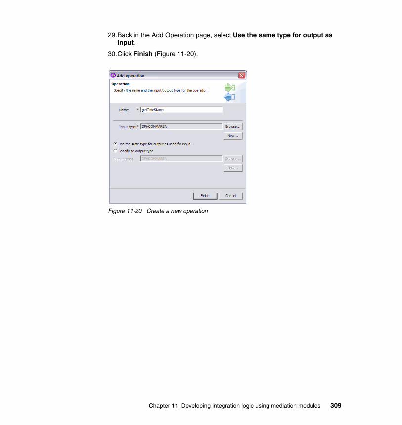
29.Back in the Add Operation page, select Use the same type for output as input.
30.Click Finish (Figure 11-20).
Figure 11-20 Create a new operation
Chapter 11. Developing integration logic using mediation modules 309
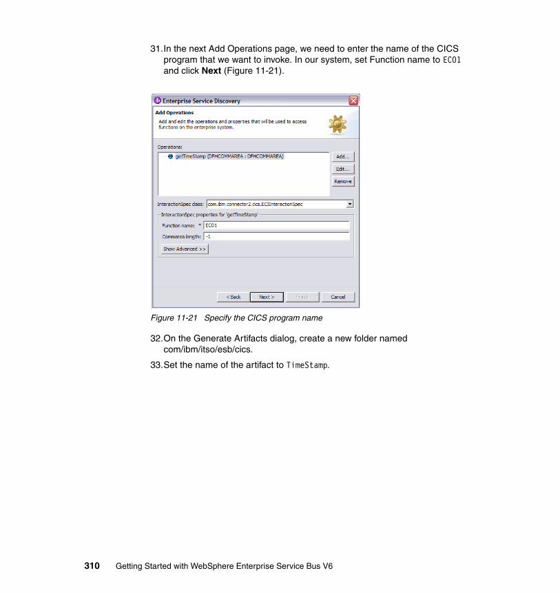
31.In the next Add Operations page, we need to enter the name of the CICS program that we want to invoke. In our system, set Function name to EC01 and click Next (Figure 11-21).
Figure 11-21 Specify the CICS program name
32.On the Generate Artifacts dialog, create a new folder named com/ibm/itso/esb/cics.
33.Set the name of the artifact to TimeStamp.
310 Getting Started with WebSphere Enterprise Service Bus V6
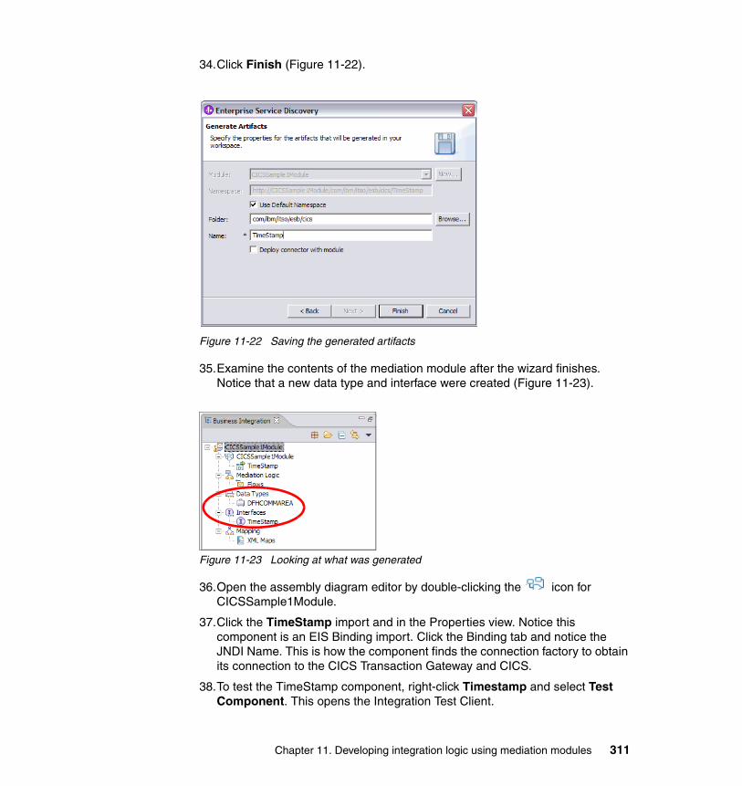
34.Click Finish (Figure 11-22).
Figure 11-22 Saving the generated artifacts
35.Examine the contents of the mediation module after the wizard finishes. Notice that a new data type and interface were created (Figure 11-23).
Figure 11-23 Looking at what was generated
36.Open the assembly diagram editor by double-clicking the icon for CICSSample1Module.
37.Click the TimeStamp import and in the Properties view. Notice this component is an EIS Binding import. Click the Binding tab and notice the JNDI Name. This is how the component finds the connection factory to obtain its connection to the CICS Transaction Gateway and CICS.
38.To test the TimeStamp component, right-click Timestamp and select Test Component. This opens the Integration Test Client.
Chapter 11. Developing integration logic using mediation modules 311
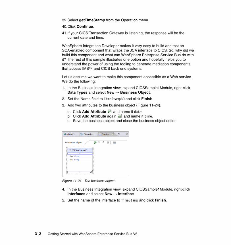
39.Select getTimeStamp from the Operation menu.
40.Click Continue.
41.If your CICS Transaction Gateway is listening, the response will be the current date and time.
WebSphere Integration Developer makes it very easy to build and test an SCA-enabled component that wraps the JCA interface to CICS. So, why did we build this component and what can WebSphere Enterprise Service Bus do with it? The rest of this sample illustrates one option and hopefully helps you to understand the power of using the tooling to generate mediation components that access IMS™ and CICS back end systems.
Let us assume we want to make this component accessible as a Web service. We do the following:
1. In the Business Integration view, expand CICSSample1Module, right-click Data Types and select New → Business Object.
2. Set the Name field to TimeStampBO and click Finish.
3. Add two attributes to the business object (Figure 11-24).
a. Click Add Attribute and name it date.b. Click Add Attribute again and name it time.c. Save the business object and close the business object editor.
Figure 11-24 The business object
4. In the Business Integration view, expand CICSSample1Module, right-click Interfaces and select New → Interface.
5. Set the name of the interface to TimeStamp and click Finish.
312 Getting Started with WebSphere Enterprise Service Bus V6

6. Define the interface (Figure 11-25).
a. Add a new 2-way operation by clicking Add Request Response Operation . Name it getStamp.
b. Add an input by clicking Add Input . and setting the Type to TimeStampBO.
c. Add an output by clicking Add Output .and setting the Type to TimeStampBO.
Figure 11-25 The TimeStamp interface
7. Save and close the interface
8. Add an export to the CICSSample1Module assembly diagram by using .
9. Rename Export1 to TimeStampServiceExport.
10.Rename Mediation1 to CICSMediation.
11.Right-click TimeStampServiceExport and select Add Interface.
12.Select the TimeStamp interface and click OK.
13.Wire the components together: TimeStampServiceExport to CICSMediation to TimeStamp (Figure 11-26).
Figure 11-26 Using the import in the assembly diagram
Chapter 11. Developing integration logic using mediation modules 313
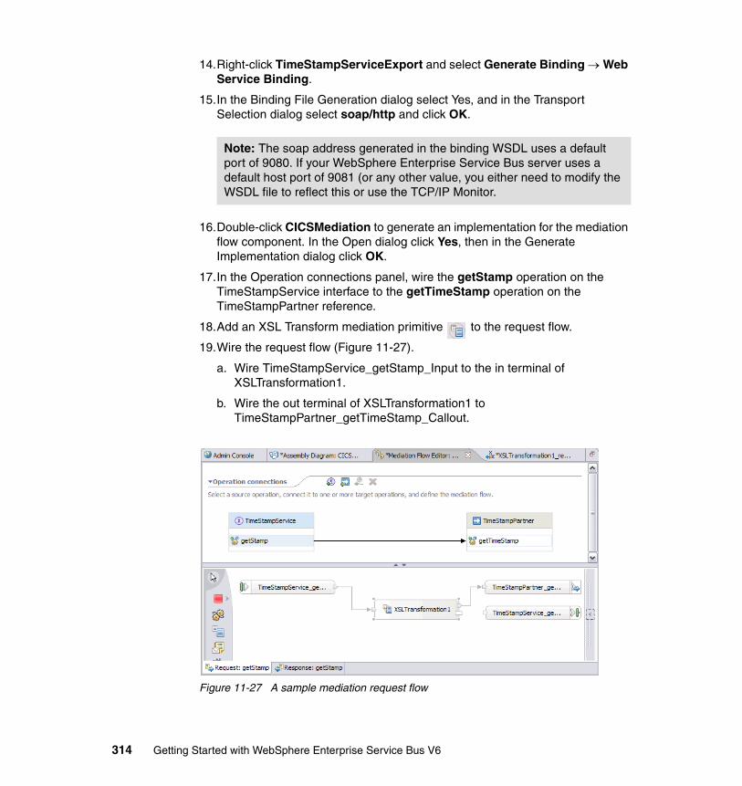
14.Right-click TimeStampServiceExport and select Generate Binding → Web Service Binding.
15.In the Binding File Generation dialog select Yes, and in the Transport Selection dialog select soap/http and click OK.
16.Double-click CICSMediation to generate an implementation for the mediation flow component. In the Open dialog click Yes, then in the Generate Implementation dialog click OK.
17.In the Operation connections panel, wire the getStamp operation on the TimeStampService interface to the getTimeStamp operation on the TimeStampPartner reference.
18.Add an XSL Transform mediation primitive to the request flow.
19.Wire the request flow (Figure 11-27).
a. Wire TimeStampService_getStamp_Input to the in terminal of XSLTransformation1.
b. Wire the out terminal of XSLTransformation1 to TimeStampPartner_getTimeStamp_Callout.
Figure 11-27 A sample mediation request flow
Note: The soap address generated in the binding WSDL uses a default port of 9080. If your WebSphere Enterprise Service Bus server uses a default host port of 9081 (or any other value, you either need to modify the WSDL file to reflect this or use the TCP/IP Monitor.
314 Getting Started with WebSphere Enterprise Service Bus V6

20.Click XSLTransform1 and in the Properties view select the Details tab.
21.Click New to create a new mapping and in the New XSLT Mapping dialog click Finish to accept the default message types.
22.Create the mapping (Figure 11-28 on page 315).
a. In the source panel select body → getStamp → input1 → date.
b. In the target panel select body → getTimeStamp → tns_1:getTimeStampInput → xsd1:ecidate.
c. In the source panel right-click date and select Create Mapping.
d. In the source panel select body → getStamp → input1 → time.
e. In the target panel select body → getTimeStamp → tns_1:getTimeStampInput → xsd1:ecitime.
f. In the source panel right-click time and select Create Mapping.
g. Save the mapping file and close it.
Figure 11-28 A simple XSLT transformation
23.Click Regenerate XSL.
24.In the mediation flow editor click the Response tab.
25.Add an XSL Transform mediation primitive to the response flow.
Chapter 11. Developing integration logic using mediation modules 315
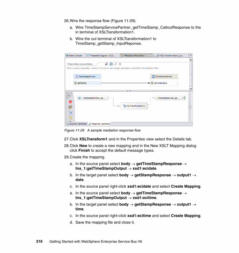
26.Wire the response flow (Figure 11-29).
a. Wire TimeStampServicePartner_getTimeStamp_CalloutResponse to the in terminal of XSLTransformation1.
b. Wire the out terminal of XSLTransformation1 to TimeStamp_getStamp_InputReponse.
Figure 11-29 A sample mediation response flow
27.Click XSLTransform1 and in the Properties view select the Details tab.
28.Click New to create a new mapping and in the New XSLT Mapping dialog click Finish to accept the default message types.
29.Create the mapping.
a. In the source panel select body → getTimeStampResponse → tns_1:getTimeStampOutput → xsd1:ecidate.
b. In the target panel select body → getStampResponse → output1 → date.
c. In the source panel right-click xsd1:ecidate and select Create Mapping.
a. In the source panel select body → getTimeStampResponse → tns_1:getTimeStampOutput → xsd1:ecitime.
b. In the target panel select body → getStampResponse → output1 → time.
c. In the source panel right-click xsd1:ecitime and select Create Mapping.
d. Save the mapping file and close it.
316 Getting Started with WebSphere Enterprise Service Bus V6
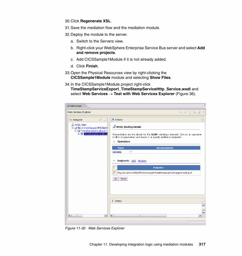
30.Click Regenerate XSL.
31.Save the mediation flow and the mediation module.
32.Deploy the module to the server.
a. Switch to the Servers view.
b. Right-click your WebSphere Enterprise Service Bus server and select Add and remove projects.
c. Add CICSSample1Module if it is not already added.
d. Click Finish.
33.Open the Physical Resources view by right-clicking the CICSSample1Module module and selecting Show Files.
34.In the CICSSample1Module project right-click TimeStampServiceExport_TimeStampServiceHttp_Service.wsdl and select Web Services → Test with Web Services Explorer (Figure 36).
Figure 11-30 Web Services Explorer
Chapter 11. Developing integration logic using mediation modules 317
35.In the Web Services Explorer, click the getStamp operation.
36.Next to Date, click Add and add the date 01-01-2006.
37.Next to Time, click Add and add the time 00:01.
38.Click Go and check the returned value which should come from CICS.
39.Remove the project from the server.
You have successfully built and tested a module that takes in a Web service request and calls a J2C connector.
11.2 Creating clients of mediation modulesThis section describes how to build clients that invoke mediation modules. Three clients are built:
� Web services client� JMS client� SCA client
Each client is invoked from a custom JSP page.
Each of the development examples in this section can be imported as Project Interchange files from the additional material supplied with this redbook in the \Clients\Solutions directory.
11.2.1 Web services clientThis example demonstrates how to create a Web services client with a JSP front-end that is capable of communicating with a mediation module. A Web services client uses Java to locate a service and invoke it. This sample involves:
� Modifying a mediation module to accept Web service requests.� Generating a Java Web service client.� Creating a JSP page to invoke the Web service client.� Using the generated client to invoke a Web service.
The completed sample demonstrates a Web services client making a request to create a new customer profile. The mediation module converts this request and invokes a Web service that creates a profile. The Web services client receives confirmation that a customer profile has been created. Follow these steps:
1. Import the XSL Transformation mediation primitive development example into your workspace.
a. Click File → Import → Project Interchange and click Next.
318 Getting Started with WebSphere Enterprise Service Bus V6
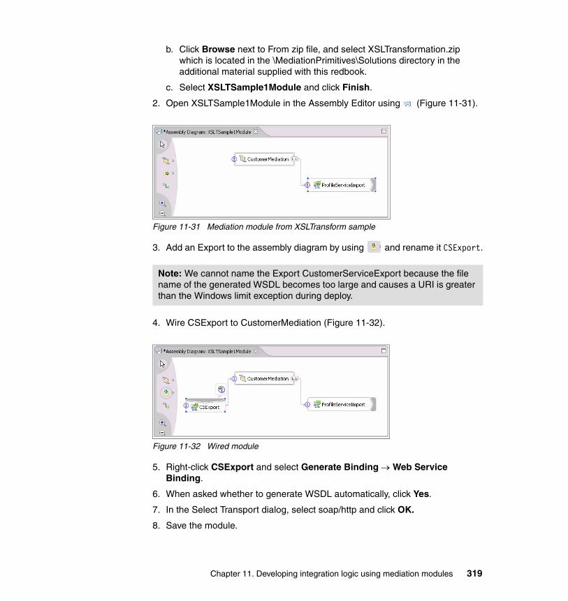
b. Click Browse next to From zip file, and select XSLTransformation.zip which is located in the \MediationPrimitives\Solutions directory in the additional material supplied with this redbook.
c. Select XSLTSample1Module and click Finish.
2. Open XSLTSample1Module in the Assembly Editor using (Figure 11-31).
Figure 11-31 Mediation module from XSLTransform sample
3. Add an Export to the assembly diagram by using and rename it CSExport.
4. Wire CSExport to CustomerMediation (Figure 11-32).
Figure 11-32 Wired module
5. Right-click CSExport and select Generate Binding → Web Service Binding.
6. When asked whether to generate WSDL automatically, click Yes.
7. In the Select Transport dialog, select soap/http and click OK.
8. Save the module.
Note: We cannot name the Export CustomerServiceExport because the file name of the generated WSDL becomes too large and causes a URI is greater than the Windows limit exception during deploy.
Chapter 11. Developing integration logic using mediation modules 319
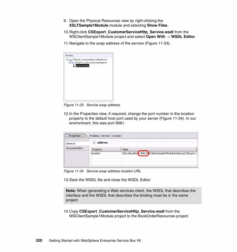
9. Open the Physical Resources view by right-clicking the XSLTSample1Module module and selecting Show Files.
10.Right-click CSExport_CustomerServiceHttp_Service.wsdl from the WSClientSample1Module project and select Open With → WSDL Editor.
11.Navigate to the soap address of the service (Figure 11-33).
Figure 11-33 Service soap address
12.In the Properties view, if required, change the port number in the location property to the default host port used by your server (Figure 11-34). In our environment, this was port 9081.
Figure 11-34 Service soap address location URL
13.Save the WSDL file and close the WSDL Editor.
14.Copy CSExport_CustomerServiceHttp_Service.wsdl from the WSClientSample1Module project to the BookOrderResources project.
Note: When generating a Web services client, the WSDL that describes the interface and the WSDL that describes the binding must be in the same project.
320 Getting Started with WebSphere Enterprise Service Bus V6
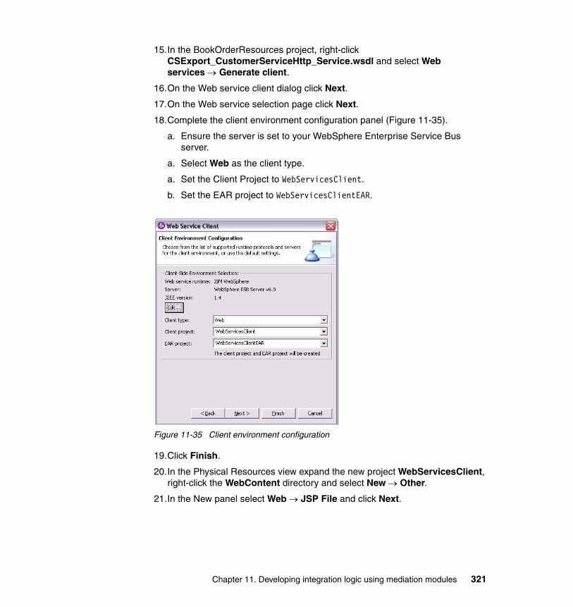
15.In the BookOrderResources project, right-click CSExport_CustomerServiceHttp_Service.wsdl and select Web services → Generate client.
16.On the Web service client dialog click Next.
17.On the Web service selection page click Next.
18.Complete the client environment configuration panel (Figure 11-35).
a. Ensure the server is set to your WebSphere Enterprise Service Bus server.
a. Select Web as the client type.
a. Set the Client Project to WebServicesClient.
b. Set the EAR project to WebServicesClientEAR.
Figure 11-35 Client environment configuration
19.Click Finish.
20.In the Physical Resources view expand the new project WebServicesClient, right-click the WebContent directory and select New → Other.
21.In the New panel select Web → JSP File and click Next.
Chapter 11. Developing integration logic using mediation modules 321
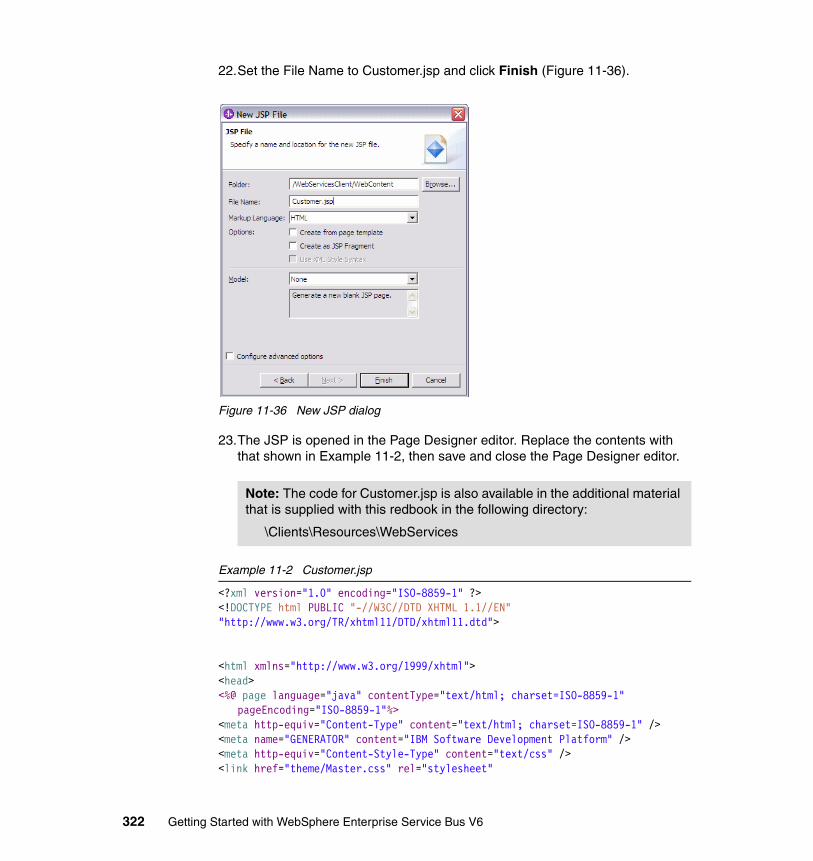
22.Set the File Name to Customer.jsp and click Finish (Figure 11-36).
Figure 11-36 New JSP dialog
23.The JSP is opened in the Page Designer editor. Replace the contents with that shown in Example 11-2, then save and close the Page Designer editor.
Example 11-2 Customer.jsp
<?xml version="1.0" encoding="ISO-8859-1" ?><!DOCTYPE html PUBLIC "-//W3C//DTD XHTML 1.1//EN" "http://www.w3.org/TR/xhtml11/DTD/xhtml11.dtd">
<html xmlns="http://www.w3.org/1999/xhtml"><head><%@ page language="java" contentType="text/html; charset=ISO-8859-1"
pageEncoding="ISO-8859-1"%><meta http-equiv="Content-Type" content="text/html; charset=ISO-8859-1" /><meta name="GENERATOR" content="IBM Software Development Platform" /><meta http-equiv="Content-Style-Type" content="text/css" /><link href="theme/Master.css" rel="stylesheet"
Note: The code for Customer.jsp is also available in the additional material that is supplied with this redbook in the following directory:
\Clients\Resources\WebServices
322 Getting Started with WebSphere Enterprise Service Bus V6
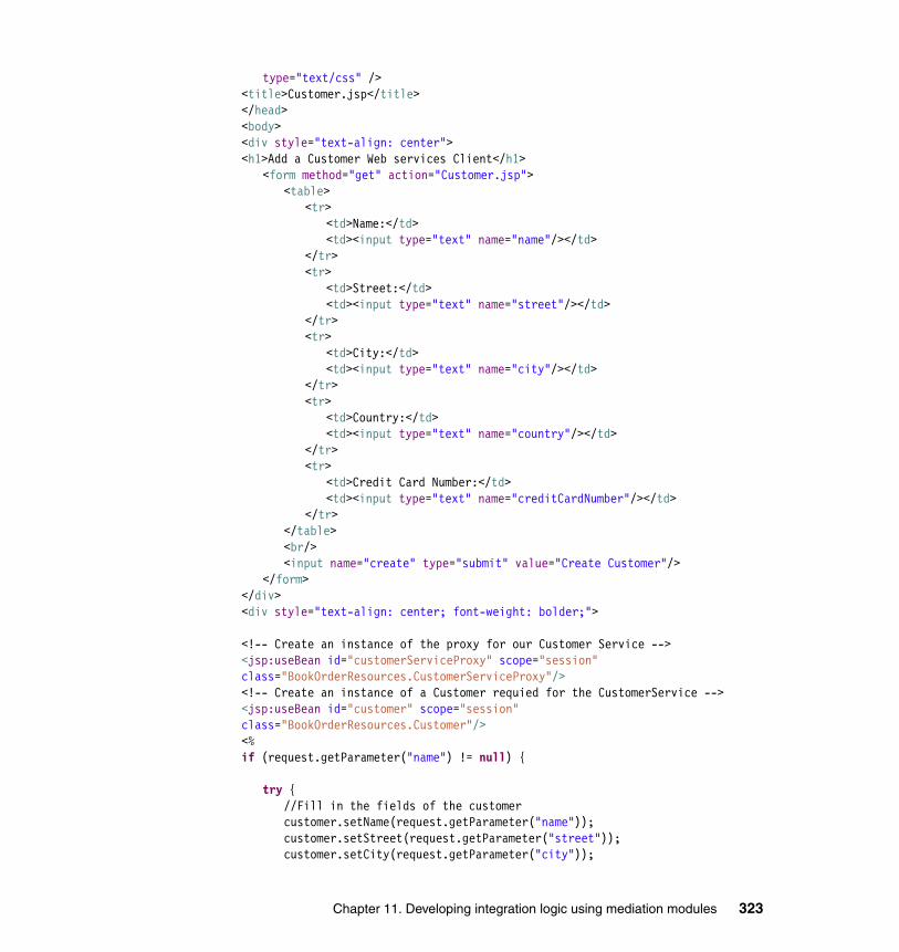
type="text/css" /><title>Customer.jsp</title></head><body><div style="text-align: center"><h1>Add a Customer Web services Client</h1>
<form method="get" action="Customer.jsp"><table>
<tr><td>Name:</td><td><input type="text" name="name"/></td>
</tr><tr>
<td>Street:</td><td><input type="text" name="street"/></td>
</tr><tr>
<td>City:</td><td><input type="text" name="city"/></td>
</tr><tr>
<td>Country:</td><td><input type="text" name="country"/></td>
</tr><tr>
<td>Credit Card Number:</td><td><input type="text" name="creditCardNumber"/></td>
</tr></table><br/><input name="create" type="submit" value="Create Customer"/>
</form></div><div style="text-align: center; font-weight: bolder;">
<!-- Create an instance of the proxy for our Customer Service --><jsp:useBean id="customerServiceProxy" scope="session" class="BookOrderResources.CustomerServiceProxy"/><!-- Create an instance of a Customer requied for the CustomerService --><jsp:useBean id="customer" scope="session" class="BookOrderResources.Customer"/><%if (request.getParameter("name") != null) {
try {//Fill in the fields of the customercustomer.setName(request.getParameter("name"));customer.setStreet(request.getParameter("street"));customer.setCity(request.getParameter("city"));
Chapter 11. Developing integration logic using mediation modules 323
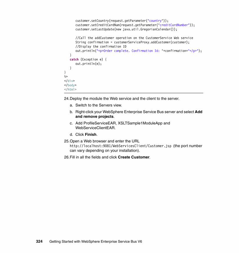
customer.setCountry(request.getParameter("country"));customer.setCreditCardNum(request.getParameter("creditCardNumber"));customer.setLastUpdate(new java.util.GregorianCalendar());
//Call the addCustomer operation on the CustomerService Web serviceString confirmation = customerServiceProxy.addCustomer(customer);//Display the confirmation IDout.println("<p>Order complete. Confirmation Id: "+confirmation+"</p>");
}catch (Exception e) {
out.println(e);}
}%></div></body></html>
24.Deploy the module the Web service and the client to the server.
a. Switch to the Servers view.
b. Right-click your WebSphere Enterprise Service Bus server and select Add and remove projects.
c. Add ProfileServiceEAR, XSLTSample1ModuleApp and WebServiceClientEAR.
d. Click Finish.
25.Open a Web browser and enter the URL http://localhost:9081/WebServicesClient/Customer.jsp (the port number can vary depending on your installation).
26.Fill in all the fields and click Create Customer.
324 Getting Started with WebSphere Enterprise Service Bus V6
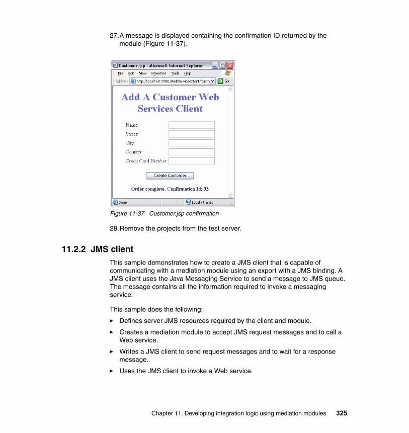
27.A message is displayed containing the confirmation ID returned by the module (Figure 11-37).
Figure 11-37 Customer.jsp confirmation
28.Remove the projects from the test server.
11.2.2 JMS clientThis sample demonstrates how to create a JMS client that is capable of communicating with a mediation module using an export with a JMS binding. A JMS client uses the Java Messaging Service to send a message to JMS queue. The message contains all the information required to invoke a messaging service.
This sample does the following:
� Defines server JMS resources required by the client and module.
� Creates a mediation module to accept JMS request messages and to call a Web service.
� Writes a JMS client to send request messages and to wait for a response message.
� Uses the JMS client to invoke a Web service.
Chapter 11. Developing integration logic using mediation modules 325
The completed sample demonstrates a JMS client making a request to create a new profile. The mediation module converts the JMS request message to a Web services request message and invokes a Web service that creates a profile. The module then converts the Web service response message to a JMS response message. The JMS client receives the response message containing confirmation that a customer profile has been created.
There are four JMS resources that are required for a mediation module to exchange messages with a JMS client:
� Input queue, which is used by the mediation module to receive request messages.
� Output queue, which is used by the mediation module to send response messages.
� QueueConnectionFactory, which is used by the mediation module to connect to the bus hosting the input and output queues.
� ActivationSpec, which is used by the mediation module to register the input queue with the mediation module’s message listener.
Create these resources using the administrative console as follows:
1. In the Servers view, right-click the WebSphere Enterprise Service Bus server and select Run administrative console.
2. Log in to the console.
3. Create the physical queues on the bus by clicking Service Integration → Buses.
4. Select SCA.APPLICATION.esbCell.Bus.
5. In the Destination resources section, click Destinations.
6. Click New and click Next to create a new Queue.
7. Set the Identifier field to profileServiceExportIn.
8. Click Next to see the Assign Queue to Bus member panel.
9. Click Next to see the Confirm queue creation panel.
10.Click Finish.
Attention: This sample requires WebSphere Enterprise Service Bus Fix Pack 1.
Note: If your WebSphere Enterprise Service Bus cell is not named esbCell, then the bus name reflects your cell name.
326 Getting Started with WebSphere Enterprise Service Bus V6

11.Create another new queue, using the same method, called profileServiceExportOut.
You should see both queues in the list of destinations (Figure 11-38).
Figure 11-38 List of destinations
We need to add references to these queues in JNDI so the client and module can access them as follows:
1. Click Resources → JMS Providers → Default messaging.
2. Under Destinations, click JMS queue.
Chapter 11. Developing integration logic using mediation modules 327

3. Click New to create a new queue (Figure 11-39).
a. Set the name field to profileServiceExportIn.
b. Set the JNDI name field to jms/profileServiceExportIn.
c. Select the SCA.APPLICATION.esbCell.Bus bus from the Bus name menu.
d. Select profileServiceExportIn from Queue name menu.
Figure 11-39 Administrative Console defining a queue.
4. Click OK.
328 Getting Started with WebSphere Enterprise Service Bus V6
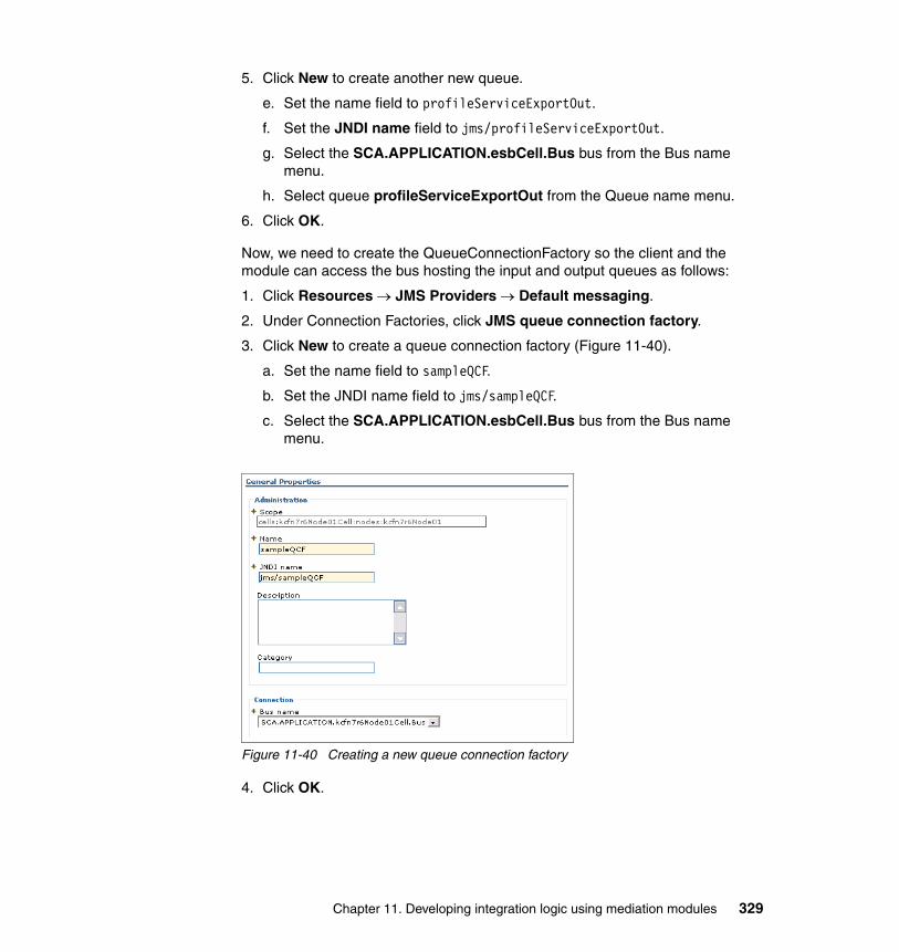
5. Click New to create another new queue.
e. Set the name field to profileServiceExportOut.
f. Set the JNDI name field to jms/profileServiceExportOut.
g. Select the SCA.APPLICATION.esbCell.Bus bus from the Bus name menu.
h. Select queue profileServiceExportOut from the Queue name menu.
6. Click OK.
Now, we need to create the QueueConnectionFactory so the client and the module can access the bus hosting the input and output queues as follows:
1. Click Resources → JMS Providers → Default messaging.
2. Under Connection Factories, click JMS queue connection factory.
3. Click New to create a queue connection factory (Figure 11-40).
a. Set the name field to sampleQCF.
b. Set the JNDI name field to jms/sampleQCF.
c. Select the SCA.APPLICATION.esbCell.Bus bus from the Bus name menu.
Figure 11-40 Creating a new queue connection factory
4. Click OK.
Chapter 11. Developing integration logic using mediation modules 329
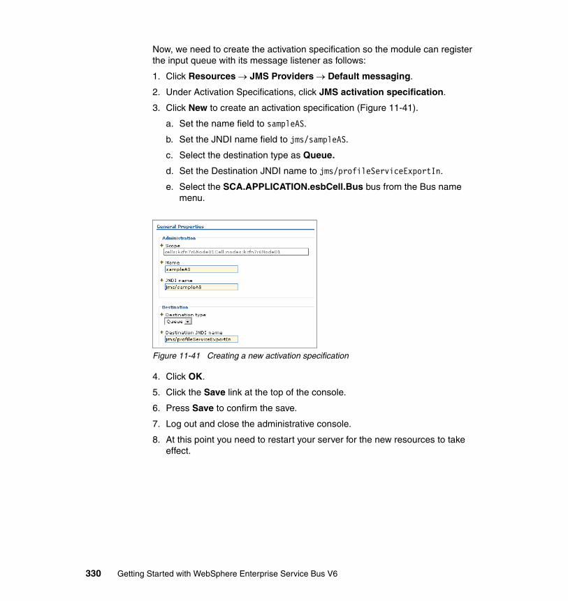
Now, we need to create the activation specification so the module can register the input queue with its message listener as follows:
1. Click Resources → JMS Providers → Default messaging.
2. Under Activation Specifications, click JMS activation specification.
3. Click New to create an activation specification (Figure 11-41).
a. Set the name field to sampleAS.
b. Set the JNDI name field to jms/sampleAS.
c. Select the destination type as Queue.
d. Set the Destination JNDI name to jms/profileServiceExportIn.
e. Select the SCA.APPLICATION.esbCell.Bus bus from the Bus name menu.
Figure 11-41 Creating a new activation specification
4. Click OK.
5. Click the Save link at the top of the console.
6. Press Save to confirm the save.
7. Log out and close the administrative console.
8. At this point you need to restart your server for the new resources to take effect.
330 Getting Started with WebSphere Enterprise Service Bus V6
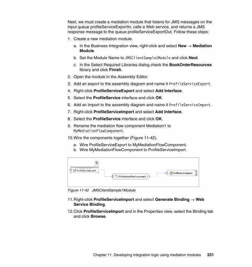
Next, we must create a mediation module that listens for JMS messages on the input queue profileServiceExportIn, calls a Web service, and returns a JMS response message to the queue profileServiceExportOut. Follow these steps:
1. Create a new mediation module.
a. In the Business Integration view, right-click and select New → Mediation Module.
b. Set the Module Name to JMSClientSample1Module and click Next.
c. In the Select Required Libraries dialog check the BookOrderResources library and click Finish.
2. Open the module in the Assembly Editor.
3. Add an export to the assembly diagram and name it ProfileServiceExport.
4. Right-click ProfileServiceExport and select Add Interface.
5. Select the ProfileService interface and click OK.
6. Add an import to the assembly diagram and name it ProfileServiceImport.
7. Right-click ProfileServiceImport and select Add Interface.
8. Select the ProfileService interface and click OK.
9. Rename the mediation flow component Mediation1 to MyMediationFlowComponent.
10.Wire the components together (Figure 11-42).
a. Wire ProfileServiceExport to MyMediationFlowComponent.b. Wire MyMediationFlowComponent to ProfileServiceImport.
Figure 11-42 JMSClientSample1Module
11.Right-click ProfileServiceImport and select Generate Binding → Web Service Binding.
12.Click ProfileServiceImport and in the Properties view, select the Binding tab and click Browse.
Chapter 11. Developing integration logic using mediation modules 331
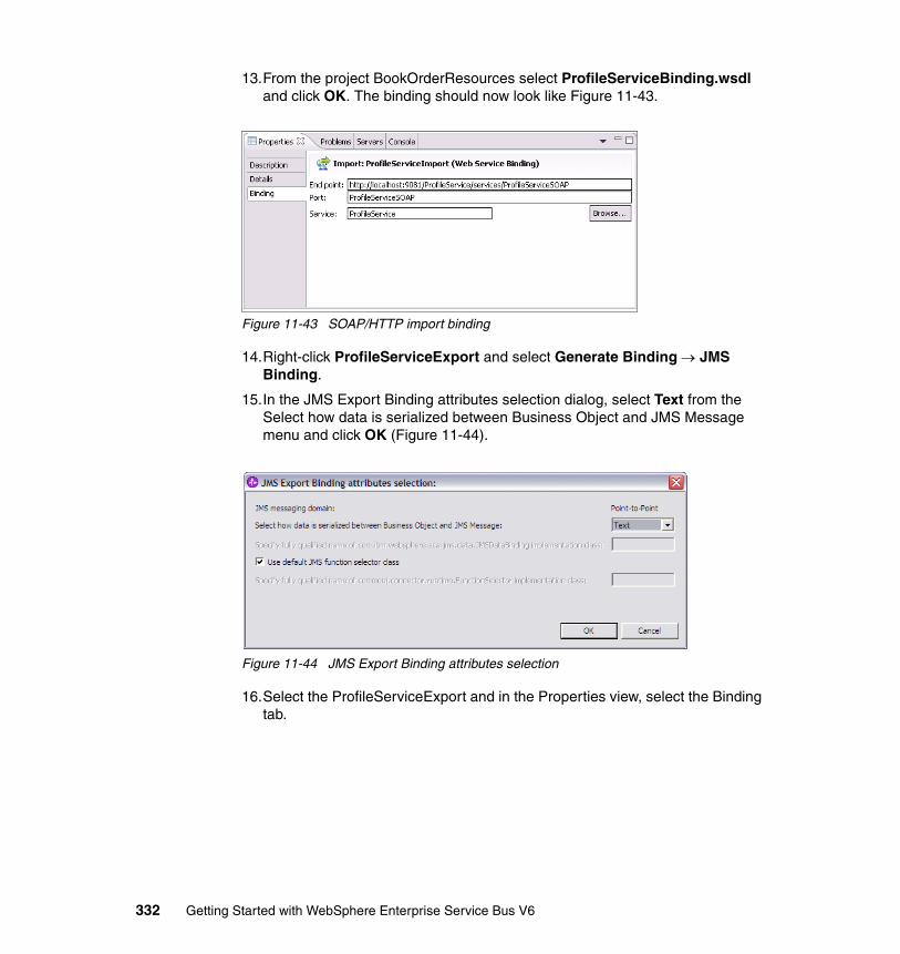
13.From the project BookOrderResources select ProfileServiceBinding.wsdl and click OK. The binding should now look like Figure 11-43.
Figure 11-43 SOAP/HTTP import binding
14.Right-click ProfileServiceExport and select Generate Binding → JMS Binding.
15.In the JMS Export Binding attributes selection dialog, select Text from the Select how data is serialized between Business Object and JMS Message menu and click OK (Figure 11-44).
Figure 11-44 JMS Export Binding attributes selection
16.Select the ProfileServiceExport and in the Properties view, select the Binding tab.
332 Getting Started with WebSphere Enterprise Service Bus V6
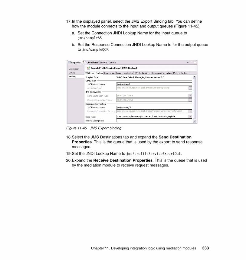
17.In the displayed panel, select the JMS Export Binding tab. You can define how the module connects to the input and output queues (Figure 11-45).
a. Set the Connection JNDI Lookup Name for the input queue to jms/sampleAS.
b. Set the Response Connection JNDI Lookup Name to for the output queue to jms/sampleQCF.
Figure 11-45 JMS Export binding
18.Select the JMS Destinations tab and expand the Send Destination Properties. This is the queue that is used by the export to send response messages.
19.Set the JNDI Lookup Name to jms/profileServiceExportOut.
20.Expand the Receive Destination Properties. This is the queue that is used by the mediation module to receive request messages.
Chapter 11. Developing integration logic using mediation modules 333

21.Set the JNDI Lookup Name to jms/profileServiceExportIn (Figure 11-46).
Figure 11-46 JMS Export binding destination properties
22.Select the Method Bindings tab.
23.Under Bound Methods click add.
24.Select com.ibm.websphere.sca.jms.data.impl.JMSDataBindingImplXML from the In Data Type menu.
25.Select com.ibm.websphere.sca.jms.data.impl.JMSDataBindingImplXML from the Out Data Type menu.
26.Back in the assembly diagram, right-click MyMediationModule and select Generate Implementation then click OK to accept the default destination. This opens the Mediation Flow Editor.
334 Getting Started with WebSphere Enterprise Service Bus V6
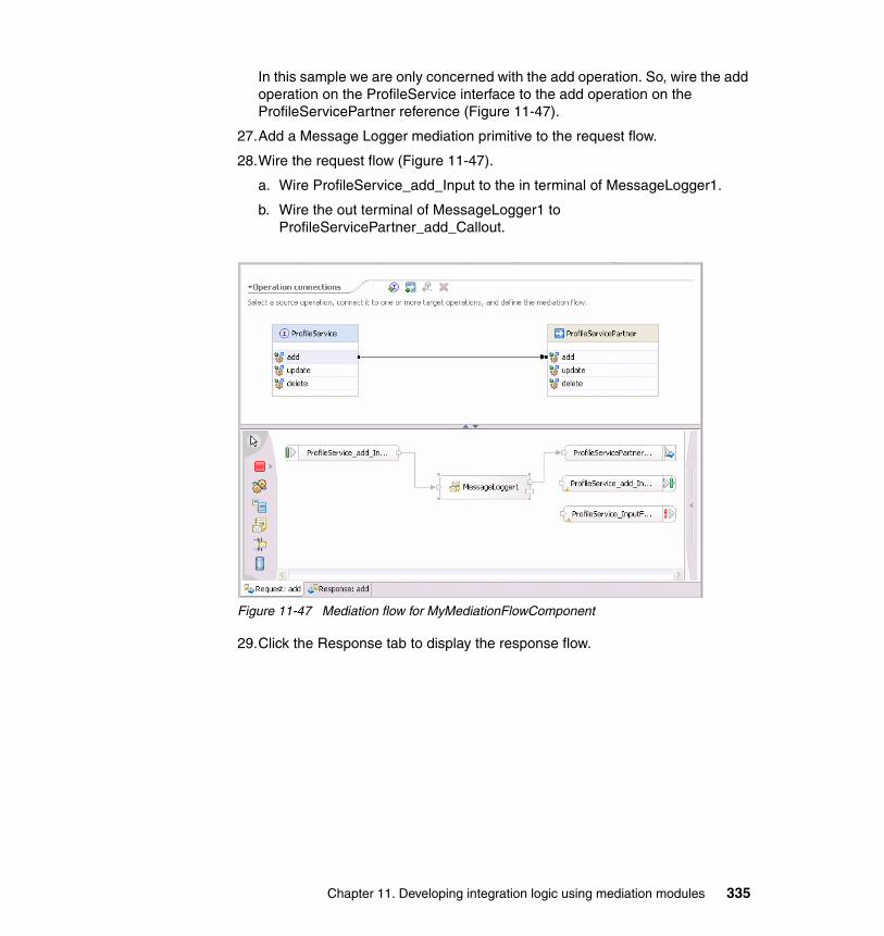
In this sample we are only concerned with the add operation. So, wire the add operation on the ProfileService interface to the add operation on the ProfileServicePartner reference (Figure 11-47).
27.Add a Message Logger mediation primitive to the request flow.
28.Wire the request flow (Figure 11-47).
a. Wire ProfileService_add_Input to the in terminal of MessageLogger1.
b. Wire the out terminal of MessageLogger1 to ProfileServicePartner_add_Callout.
Figure 11-47 Mediation flow for MyMediationFlowComponent
29.Click the Response tab to display the response flow.
Chapter 11. Developing integration logic using mediation modules 335
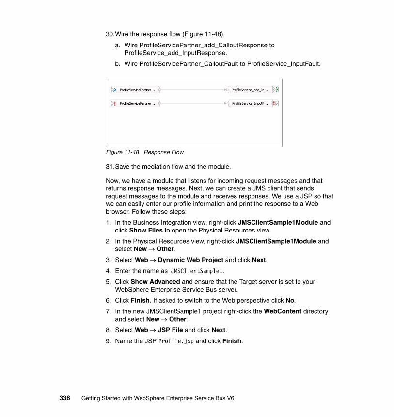
30.Wire the response flow (Figure 11-48).
a. Wire ProfileServicePartner_add_CalloutResponse to ProfileService_add_InputResponse.
b. Wire ProfileServicePartner_CalloutFault to ProfileService_InputFault.
Figure 11-48 Response Flow
31.Save the mediation flow and the module.
Now, we have a module that listens for incoming request messages and that returns response messages. Next, we can create a JMS client that sends request messages to the module and receives responses. We use a JSP so that we can easily enter our profile information and print the response to a Web browser. Follow these steps:
1. In the Business Integration view, right-click JMSClientSample1Module and click Show Files to open the Physical Resources view.
2. In the Physical Resources view, right-click JMSClientSample1Module and select New → Other.
3. Select Web → Dynamic Web Project and click Next.
4. Enter the name as JMSClientSample1.
5. Click Show Advanced and ensure that the Target server is set to your WebSphere Enterprise Service Bus server.
6. Click Finish. If asked to switch to the Web perspective click No.
7. In the new JMSClientSample1 project right-click the WebContent directory and select New → Other.
8. Select Web → JSP File and click Next.
9. Name the JSP Profile.jsp and click Finish.
336 Getting Started with WebSphere Enterprise Service Bus V6
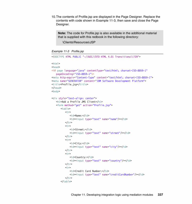
10.The contents of Profile.jsp are displayed in the Page Designer. Replace the contents with code shown in Example 11-3, then save and close the Page Designer.
Example 11-3 Profile.jsp
<!DOCTYPE HTML PUBLIC "-//W3C//DTD HTML 4.01 Transitional//EN">
<html><head><%@ page language="java" contentType="text/html; charset=ISO-8859-1"
pageEncoding="ISO-8859-1"%><meta http-equiv="Content-Type" content="text/html; charset=ISO-8859-1"><meta name="GENERATOR" content="IBM Software Development Platform"><title>Profile.jsp</title></head><body>
<div style="text-align: center"><h1>Add a Profile JMS Client</h1><form method="get" action="Profile.jsp">
<table><tr>
<td>Name:</td><td><input type="text" name="name"/></td>
</tr><tr>
<td>Street:</td><td><input type="text" name="street"/></td>
</tr><tr>
<td>City:</td><td><input type="text" name="city"/></td>
</tr><tr>
<td>Country:</td><td><input type="text" name="country"/></td>
</tr><tr>
<td>Credit Card Number:</td><td><input type="text" name="creditCardNumber"/></td>
</tr></table>
Note: The code for Profile.jsp is also available in the additional material that is supplied with this redbook in the following directory:
\Clients\Resources\JSP
Chapter 11. Developing integration logic using mediation modules 337

<br/><input name="create" type="submit" value="Create Profile"/>
</form>
<%if (request.getParameter("name") != null) {
//The Initial Context FactoryString icf = "com.ibm.websphere.naming.WsnInitialContextFactory";//the Provider URLString url = "iiop://localhost:2810/";//The Queue Connection Factory used to connect to the busString sampleQCF = "jms/sampleQCF";//The Queue used to send requests to the mediation moduleString sampleSendQueue = "jms/profileServiceExportIn";//The Queue used to receive responses from the mediation moduleString sampleReceiveQueue = "jms/profileServiceExportOut";//The XML representation of a Profile which is the Business Object required
by the add operation//on the ProfileService InterfaceString message = "<?xml version=\"1.0\" encoding=\"UTF-8\"?>";message += "<xs1:Profile xmlns:xs1=\"http://BookOrderResources\">";message += "<name>"+request.getParameter("name")+"</name>";message += "<xs2:Address xmlns:xs2=\"http://BookOrderResources\">";message += "<street>"+request.getParameter("street")+"</street>";message += "<city>"+request.getParameter("city")+"</city>";message += "<country>"+request.getParameter("country")+"</country>";message += "</xs2:Address>";message +=
"<creditCardNum>"+request.getParameter("creditCardNum")+"</creditCardNum>";message += "<lastUpdate>2006-02-16</lastUpdate>";message += "</xs1:Profile>";
try {//Create the Initial Context
java.util.Hashtable env = new java.util.Hashtable(); env.put(javax.naming.Context.INITIAL_CONTEXT_FACTORY, icf); env.put(javax.naming.Context.PROVIDER_URL, url); javax.naming.Context ctx = new javax.naming.directory.InitialDirContext(env); //Lookup the ConnectionFactory javax.jms.ConnectionFactory factory = (javax.jms.ConnectionFactory)ctx.lookup(sampleQCF);
//Create a Connection javax.jms.Connection connection = factory.createConnection(); //Start the Connection connection.start(); //Create a Session
338 Getting Started with WebSphere Enterprise Service Bus V6
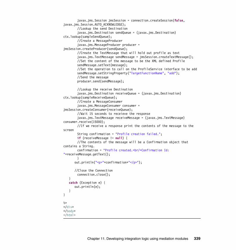
javax.jms.Session jmsSession = connection.createSession(false, javax.jms.Session.AUTO_ACKNOWLEDGE); //Lookup the send Destination javax.jms.Destination sendQueue = (javax.jms.Destination) ctx.lookup(sampleSendQueue); //Create a MessageProducer javax.jms.MessageProducer producer = jmsSession.createProducer(sendQueue); //Create the TextMessage that will hold out profile as text javax.jms.TextMessage sendMessage = jmsSession.createTextMessage(); //Set the content of the message to be the XML defined Profile sendMessage.setText(message); //Set the operation to call on the ProfileService interface to be add sendMessage.setStringProperty("TargetFunctionName", "add"); //Send the message producer.send(sendMessage); //Lookup the receive Destination javax.jms.Destination receiveQueue = (javax.jms.Destination) ctx.lookup(sampleReceiveQueue); //Create a MessageConsumer javax.jms.MessageConsumer consumer = jmsSession.createConsumer(receiveQueue); //Wait 15 seconds to receieve the response javax.jms.TextMessage receiveMessage = (javax.jms.TextMessage) consumer.receive(15000); //If we receive a response print the contents of the message to the screen String confirmation = "Profile creation failed."; if (receiveMessage != null) { //The contents of the message will be a Confirmation object that contains a String. confirmation = "Profile created.<br/>Confirmation Id: "+receiveMessage.getText(); }
out.println("<p>"+confirmation+"</p>");
//Close the Connection connection.close();
}catch (Exception e) {
out.println(e);}
}
%></div></body></html>
Chapter 11. Developing integration logic using mediation modules 339
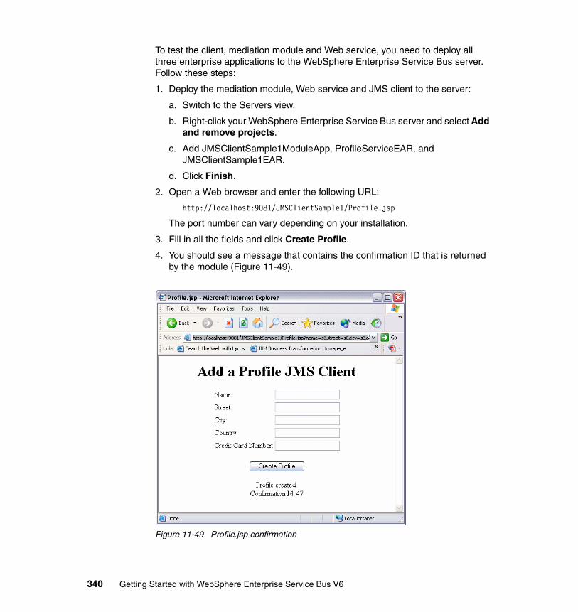
To test the client, mediation module and Web service, you need to deploy all three enterprise applications to the WebSphere Enterprise Service Bus server. Follow these steps:
1. Deploy the mediation module, Web service and JMS client to the server:
a. Switch to the Servers view.
b. Right-click your WebSphere Enterprise Service Bus server and select Add and remove projects.
c. Add JMSClientSample1ModuleApp, ProfileServiceEAR, and JMSClientSample1EAR.
d. Click Finish.
2. Open a Web browser and enter the following URL:
http://localhost:9081/JMSClientSample1/Profile.jsp
The port number can vary depending on your installation.
3. Fill in all the fields and click Create Profile.
4. You should see a message that contains the confirmation ID that is returned by the module (Figure 11-49).
Figure 11-49 Profile.jsp confirmation
340 Getting Started with WebSphere Enterprise Service Bus V6
You have successfully demonstrated how to create a JMS client and mediation module that allows this client to communicate with a Web service.
5. Remove the projects from the test server.
11.2.3 SCA clientThis sample demonstrates how to use the SCA programming model to create a client that is capable of communicating with a mediation module. An SCA client uses the Java SCA programming model to communicate with an SCA component.
This sample does the following:
� Creates a mediation module to accept SCA calls and to return a response.� Writes an SCA client to send requests and to receive responses.� Uses the SCA client to invoke an operation on the SCA module.
The completed sample demonstrates an SCA client making a request to order a book. The mediation module uses a Java component to return a confirmation of the order. The client receives a confirmation that the order was successful. Follow these steps:
1. Create a new mediation module.
a. In the Business Integration view, right-click and select New → Mediation Module.
b. Set the Module Name to SCAClientSample1Module and click Next.
c. In the Select Required Libraries dialog check the BookOrderResources library and click Finish.
2. Open the module in the Assembly Editor by double-clicking .
3. Right-click Mediation1 and select Delete. The mediation flow component is not required to test the SCA client.
4. Create a stand-alone reference to allow an SCA client to communicate with the module as follows:
a. In the Assembly Editor, add a stand-alone reference to the assembly diagram.
b. Right-click the stand-alone reference and select Add Reference.
c. Select the BookOrderService and click OK.
d. If asked to convert the WSDL interface to a Java interface click Yes.
Note: We use a Java component to implement the BookOrderService.
Chapter 11. Developing integration logic using mediation modules 341
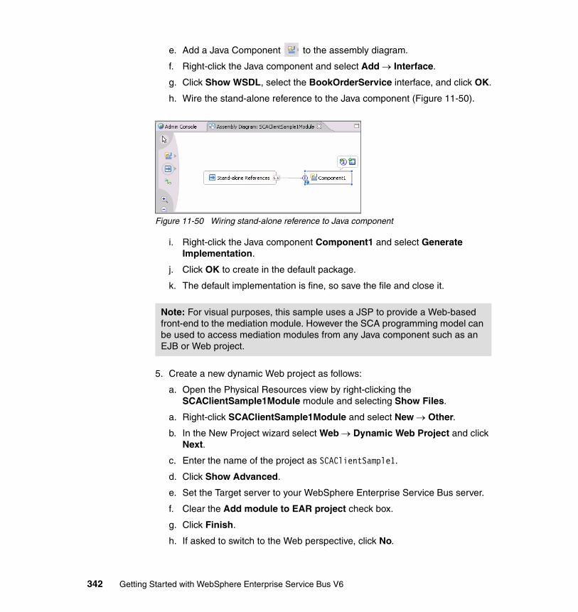
e. Add a Java Component to the assembly diagram.
f. Right-click the Java component and select Add → Interface.
g. Click Show WSDL, select the BookOrderService interface, and click OK.
h. Wire the stand-alone reference to the Java component (Figure 11-50).
Figure 11-50 Wiring stand-alone reference to Java component
i. Right-click the Java component Component1 and select Generate Implementation.
j. Click OK to create in the default package.
k. The default implementation is fine, so save the file and close it.
5. Create a new dynamic Web project as follows:
a. Open the Physical Resources view by right-clicking the SCAClientSample1Module module and selecting Show Files.
a. Right-click SCAClientSample1Module and select New → Other.
b. In the New Project wizard select Web → Dynamic Web Project and click Next.
c. Enter the name of the project as SCAClientSample1.
d. Click Show Advanced.
e. Set the Target server to your WebSphere Enterprise Service Bus server.
f. Clear the Add module to EAR project check box.
g. Click Finish.
h. If asked to switch to the Web perspective, click No.
Note: For visual purposes, this sample uses a JSP to provide a Web-based front-end to the mediation module. However the SCA programming model can be used to access mediation modules from any Java component such as an EJB or Web project.
342 Getting Started with WebSphere Enterprise Service Bus V6
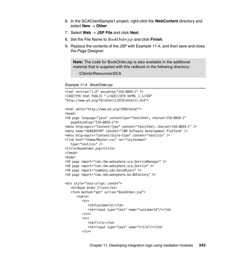
6. In the SCAClientSample1 project, right-click the WebContent directory and select New → Other.
7. Select Web → JSP File and click Next.
8. Set the File Name to BookOrder.jsp and click Finish.
9. Replace the contents of the JSP with Example 11-4, and then save and close the Page Designer.
Example 11-4 BookOrder.jsp
<?xml version="1.0" encoding="ISO-8859-1" ?><!DOCTYPE html PUBLIC "-//W3C//DTD XHTML 1.1//EN" "http://www.w3.org/TR/xhtml11/DTD/xhtml11.dtd">
<html xmlns="http://www.w3.org/1999/xhtml"><head><%@ page language="java" contentType="text/html; charset=ISO-8859-1"
pageEncoding="ISO-8859-1"%><meta http-equiv="Content-Type" content="text/html; charset=ISO-8859-1" /><meta name="GENERATOR" content="IBM Software Development Platform" /><meta http-equiv="Content-Style-Type" content="text/css" /><link href="theme/Master.css" rel="stylesheet"
type="text/css" /><title>BookOrder.jsp</title></head><body><%@ page import="com.ibm.websphere.sca.ServiceManager" %><%@ page import="com.ibm.websphere.sca.Service" %><%@ page import="commonj.sdo.DataObject" %><%@ page import="com.ibm.websphere.bo.BOFactory" %>
<div style="text-align: center"><h1>Book Order Client</h1><form method="get" action="BookOrder.jsp">
<table><tr>
<td>CustomerId:</td><td><input type="text" name="customerId"/></td>
</tr><tr>
<td>Title:</td><td><input type="text" name="title"/></td>
</tr>
Note: The code for BookOrder.jsp is also available in the additional material that is supplied with this redbook in the following directory:
\Clients\Resources\SCA
Chapter 11. Developing integration logic using mediation modules 343
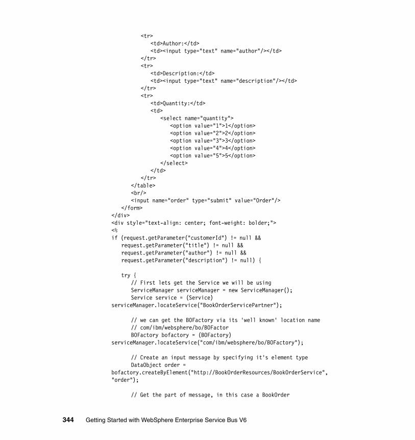
<tr><td>Author:</td><td><input type="text" name="author"/></td>
</tr><tr>
<td>Description:</td><td><input type="text" name="description"/></td>
</tr><tr>
<td>Quantity:</td><td>
<select name="quantity"><option value="1">1</option><option value="2">2</option><option value="3">3</option><option value="4">4</option><option value="5">5</option>
</select></td>
</tr></table><br/><input name="order" type="submit" value="Order"/>
</form></div><div style="text-align: center; font-weight: bolder;"><%if (request.getParameter("customerId") != null &&
request.getParameter("title") != null &&request.getParameter("author") != null &&request.getParameter("description") != null) {
try {// First lets get the Service we will be usingServiceManager serviceManager = new ServiceManager();Service service = (Service)
serviceManager.locateService("BookOrderServicePartner");
// we can get the BOFactory via its 'well known' location name// com/ibm/websphere/bo/BOFactorBOFactory bofactory = (BOFactory)
serviceManager.locateService("com/ibm/websphere/bo/BOFactory");
// Create an input message by specifying it's element typeDataObject order =
bofactory.createByElement("http://BookOrderResources/BookOrderService", "order");
// Get the part of message, in this case a BookOrder
344 Getting Started with WebSphere Enterprise Service Bus V6
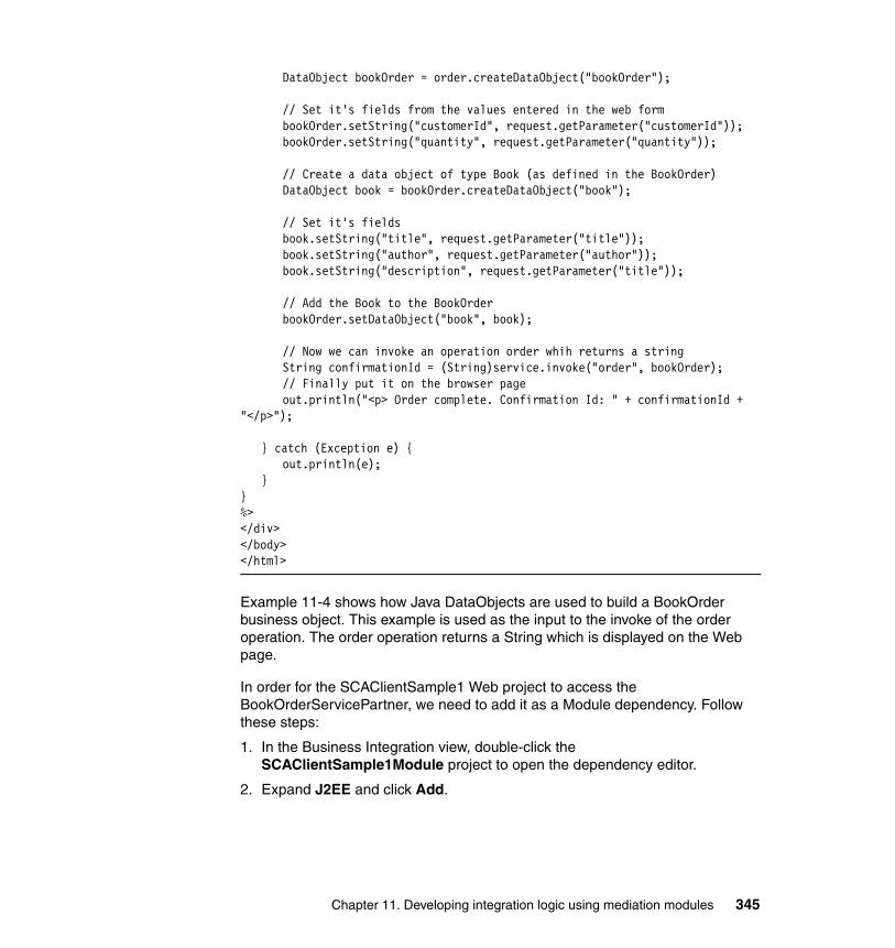
DataObject bookOrder = order.createDataObject("bookOrder");
// Set it's fields from the values entered in the web formbookOrder.setString("customerId", request.getParameter("customerId"));bookOrder.setString("quantity", request.getParameter("quantity"));
// Create a data object of type Book (as defined in the BookOrder)DataObject book = bookOrder.createDataObject("book");
// Set it's fieldsbook.setString("title", request.getParameter("title"));book.setString("author", request.getParameter("author"));book.setString("description", request.getParameter("title"));
// Add the Book to the BookOrderbookOrder.setDataObject("book", book);
// Now we can invoke an operation order whih returns a stringString confirmationId = (String)service.invoke("order", bookOrder);// Finally put it on the browser pageout.println("<p> Order complete. Confirmation Id: " + confirmationId +
"</p>");
} catch (Exception e) {out.println(e);
}}%></div></body></html>
Example 11-4 shows how Java DataObjects are used to build a BookOrder business object. This example is used as the input to the invoke of the order operation. The order operation returns a String which is displayed on the Web page.
In order for the SCAClientSample1 Web project to access the BookOrderServicePartner, we need to add it as a Module dependency. Follow these steps:
1. In the Business Integration view, double-click the SCAClientSample1Module project to open the dependency editor.
2. Expand J2EE and click Add.
Chapter 11. Developing integration logic using mediation modules 345

3. Select the SCAClientSample1 Web project and click OK (Figure 11-51).
Figure 11-51 Adding module dependencies
4. Save and close the dependencies editor.
Now, test the JSP.
1. Deploy the module to the server.
a. Switch to the Servers view.
b. Right-click your WebSphere Enterprise Service Bus server and select Add and remove projects.
c. Add SCAClientSample1ModuleApp.
d. Click Finish.
2. Enter the following URL into a Web browser:
http://localhost:9081/SCAClientSample1/BookOrder.jsp
The port number can vary depending on your installation.
346 Getting Started with WebSphere Enterprise Service Bus V6
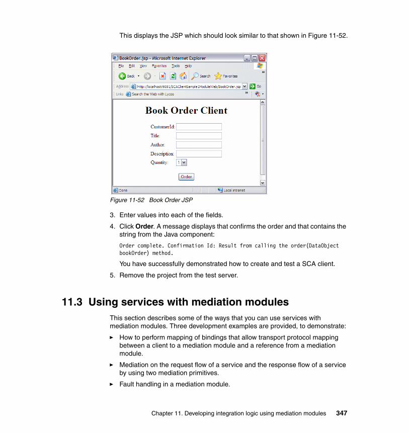
This displays the JSP which should look similar to that shown in Figure 11-52.
Figure 11-52 Book Order JSP
3. Enter values into each of the fields.
4. Click Order. A message displays that confirms the order and that contains the string from the Java component:
Order complete. Confirmation Id: Result from calling the order(DataObject bookOrder) method.
You have successfully demonstrated how to create and test a SCA client.
5. Remove the project from the test server.
11.3 Using services with mediation modulesThis section describes some of the ways that you can use services with mediation modules. Three development examples are provided, to demonstrate:
� How to perform mapping of bindings that allow transport protocol mapping between a client to a mediation module and a reference from a mediation module.
� Mediation on the request flow of a service and the response flow of a service by using two mediation primitives.
� Fault handling in a mediation module.
Chapter 11. Developing integration logic using mediation modules 347
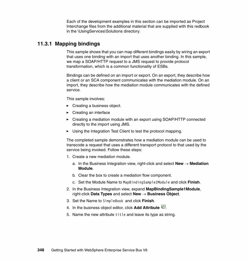
Each of the development examples in this section can be imported as Project Interchange files from the additional material that are supplied with this redbook in the \UsingServices\Solutions directory.
11.3.1 Mapping bindingsThis sample shows that you can map different bindings easily by wiring an export that uses one binding with an import that uses another binding. In this sample, we map a SOAP/HTTP request to a JMS request to provide protocol transformation, which is a common functionality of ESBs.
Bindings can be defined on an import or export. On an export, they describe how a client or an SCA component communicates with the mediation module. On an import, they describe how the mediation module communicates with the defined service.
This sample involves:
� Creating a business object.
� Creating an interface
� Creating a mediation module with an export using SOAP/HTTP connected directly to the import using JMS.
� Using the Integration Test Client to test the protocol mapping.
The completed sample demonstrates how a mediation module can be used to transcode a request that uses a different transport protocol to that used by the service being invoked. Follow these steps:
1. Create a new mediation module.
a. In the Business Integration view, right-click and select New → Mediation Module.
b. Clear the box to create a mediation flow component.
c. Set the Module Name to MapBindingSample1Module and click Finish.
2. In the Business Integration view, expand MapBindingSample1Module, right-click Data Types and select New → Business Object.
3. Set the Name to SimpleBook and click Finish.
4. In the business object editor, click Add Attribute .
5. Name the new attribute title and leave its type as string.
348 Getting Started with WebSphere Enterprise Service Bus V6
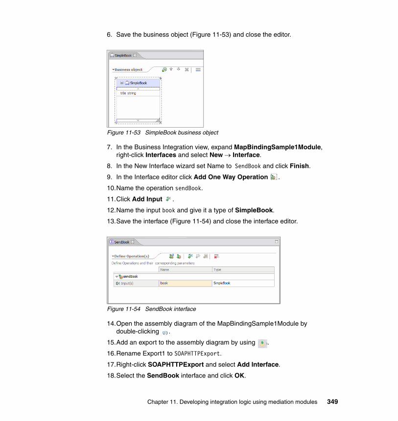
6. Save the business object (Figure 11-53) and close the editor.
Figure 11-53 SimpleBook business object
7. In the Business Integration view, expand MapBindingSample1Module, right-click Interfaces and select New → Interface.
8. In the New Interface wizard set Name to SendBook and click Finish.
9. In the Interface editor click Add One Way Operation .
10.Name the operation sendBook.
11.Click Add Input .
12.Name the input book and give it a type of SimpleBook.
13.Save the interface (Figure 11-54) and close the interface editor.
Figure 11-54 SendBook interface
14.Open the assembly diagram of the MapBindingSample1Module by double-clicking .
15.Add an export to the assembly diagram by using .
16.Rename Export1 to SOAPHTTPExport.
17.Right-click SOAPHTTPExport and select Add Interface.
18.Select the SendBook interface and click OK.
Chapter 11. Developing integration logic using mediation modules 349
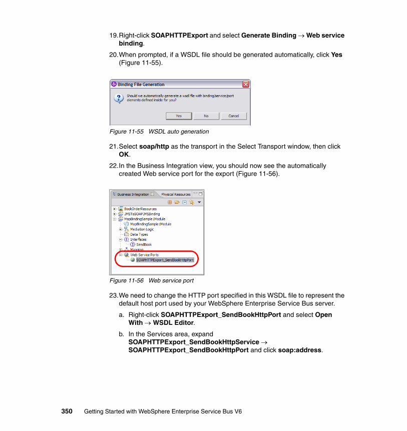
19.Right-click SOAPHTTPExport and select Generate Binding → Web service binding.
20.When prompted, if a WSDL file should be generated automatically, click Yes (Figure 11-55).
Figure 11-55 WSDL auto generation
21.Select soap/http as the transport in the Select Transport window, then click OK.
22.In the Business Integration view, you should now see the automatically created Web service port for the export (Figure 11-56).
Figure 11-56 Web service port
23.We need to change the HTTP port specified in this WSDL file to represent the default host port used by your WebSphere Enterprise Service Bus server.
a. Right-click SOAPHTTPExport_SendBookHttpPort and select Open With → WSDL Editor.
b. In the Services area, expand SOAPHTTPExport_SendBookHttpService → SOAPHTTPExport_SendBookHttpPort and click soap:address.
350 Getting Started with WebSphere Enterprise Service Bus V6
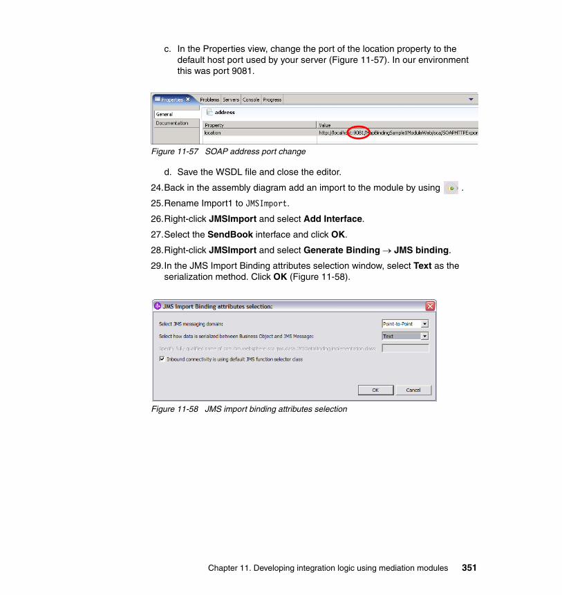
c. In the Properties view, change the port of the location property to the default host port used by your server (Figure 11-57). In our environment this was port 9081.
Figure 11-57 SOAP address port change
d. Save the WSDL file and close the editor.
24.Back in the assembly diagram add an import to the module by using .
25.Rename Import1 to JMSImport.
26.Right-click JMSImport and select Add Interface.
27.Select the SendBook interface and click OK.
28.Right-click JMSImport and select Generate Binding → JMS binding.
29.In the JMS Import Binding attributes selection window, select Text as the serialization method. Click OK (Figure 11-58).
Figure 11-58 JMS import binding attributes selection
Chapter 11. Developing integration logic using mediation modules 351
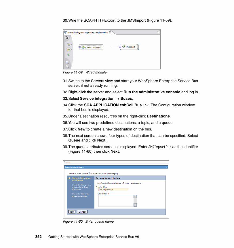
30.Wire the SOAPHTTPExport to the JMSImport (Figure 11-59).
Figure 11-59 Wired module
31.Switch to the Servers view and start your WebSphere Enterprise Service Bus server, if not already running.
32.Right-click the server and select Run the administrative console and log in.
33.Select Service integration → Buses.
34.Click the SCA.APPLICATION.esbCell.Bus link. The Configuration window for that bus is displayed.
35.Under Destination resources on the right-click Destinations.
36.You will see two predefined destinations, a topic, and a queue.
37.Click New to create a new destination on the bus.
38.The next screen shows four types of destination that can be specified. Select Queue and click Next.
39.The queue attributes screen is displayed. Enter JMSImportOut as the identifier (Figure 11-60) then click Next.
Figure 11-60 Enter queue name
352 Getting Started with WebSphere Enterprise Service Bus V6
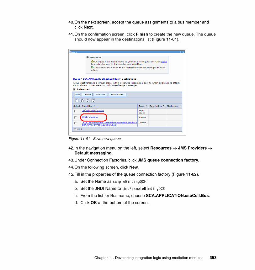
40.On the next screen, accept the queue assignments to a bus member and click Next.
41.On the confirmation screen, click Finish to create the new queue. The queue should now appear in the destinations list (Figure 11-61).
Figure 11-61 Save new queue
42.In the navigation menu on the left, select Resources → JMS Providers → Default messaging.
43.Under Connection Factories, click JMS queue connection factory.
44.On the following screen, click New.
45.Fill in the properties of the queue connection factory (Figure 11-62).
a. Set the Name as sampleBindingQCF.
b. Set the JNDI Name to jms/sampleBindingQCF.
c. From the list for Bus name, choose SCA.APPLICATION.esbCell.Bus.
d. Click OK at the bottom of the screen.
Chapter 11. Developing integration logic using mediation modules 353
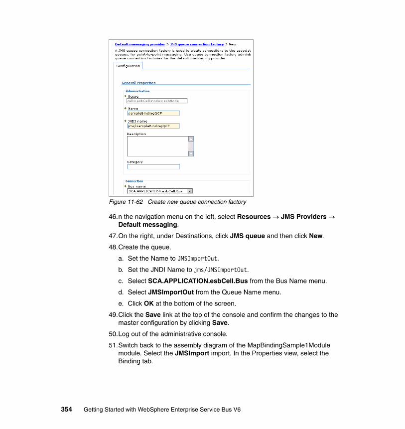
Figure 11-62 Create new queue connection factory
46.n the navigation menu on the left, select Resources → JMS Providers → Default messaging.
47.On the right, under Destinations, click JMS queue and then click New.
48.Create the queue.
a. Set the Name to JMSImportOut.
b. Set the JNDI Name to jms/JMSImportOut.
c. Select SCA.APPLICATION.esbCell.Bus from the Bus Name menu.
d. Select JMSImportOut from the Queue Name menu.
e. Click OK at the bottom of the screen.
49.Click the Save link at the top of the console and confirm the changes to the master configuration by clicking Save.
50.Log out of the administrative console.
51.Switch back to the assembly diagram of the MapBindingSample1Module module. Select the JMSImport import. In the Properties view, select the Binding tab.
354 Getting Started with WebSphere Enterprise Service Bus V6
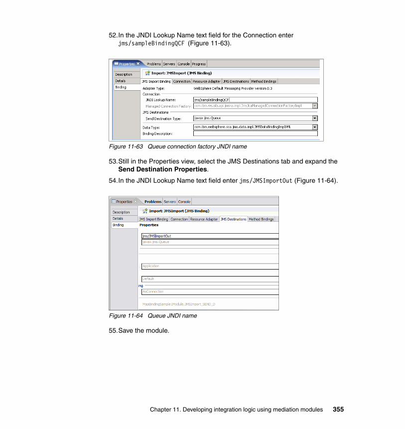
52.In the JNDI Lookup Name text field for the Connection enter jms/sampleBindingQCF (Figure 11-63).
Figure 11-63 Queue connection factory JNDI name
53.Still in the Properties view, select the JMS Destinations tab and expand the Send Destination Properties.
54.In the JNDI Lookup Name text field enter jms/JMSImportOut (Figure 11-64).
Figure 11-64 Queue JNDI name
55.Save the module.
Chapter 11. Developing integration logic using mediation modules 355
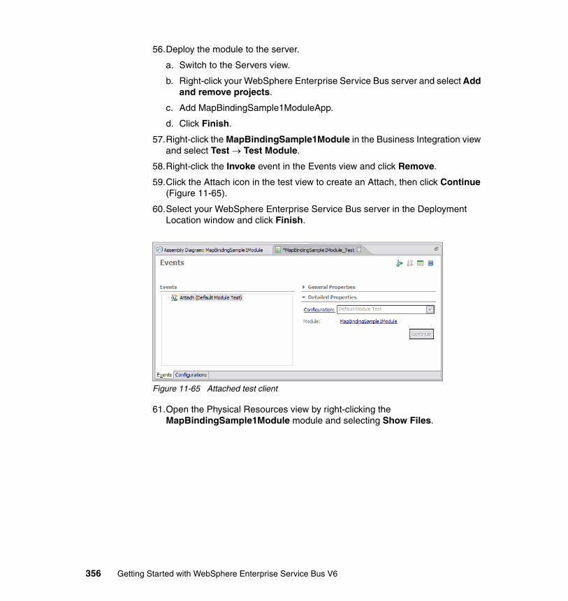
56.Deploy the module to the server.
a. Switch to the Servers view.
b. Right-click your WebSphere Enterprise Service Bus server and select Add and remove projects.
c. Add MapBindingSample1ModuleApp.
d. Click Finish.
57.Right-click the MapBindingSample1Module in the Business Integration view and select Test → Test Module.
58.Right-click the Invoke event in the Events view and click Remove.
59.Click the Attach icon in the test view to create an Attach, then click Continue (Figure 11-65).
60.Select your WebSphere Enterprise Service Bus server in the Deployment Location window and click Finish.
Figure 11-65 Attached test client
61.Open the Physical Resources view by right-clicking the MapBindingSample1Module module and selecting Show Files.
356 Getting Started with WebSphere Enterprise Service Bus V6
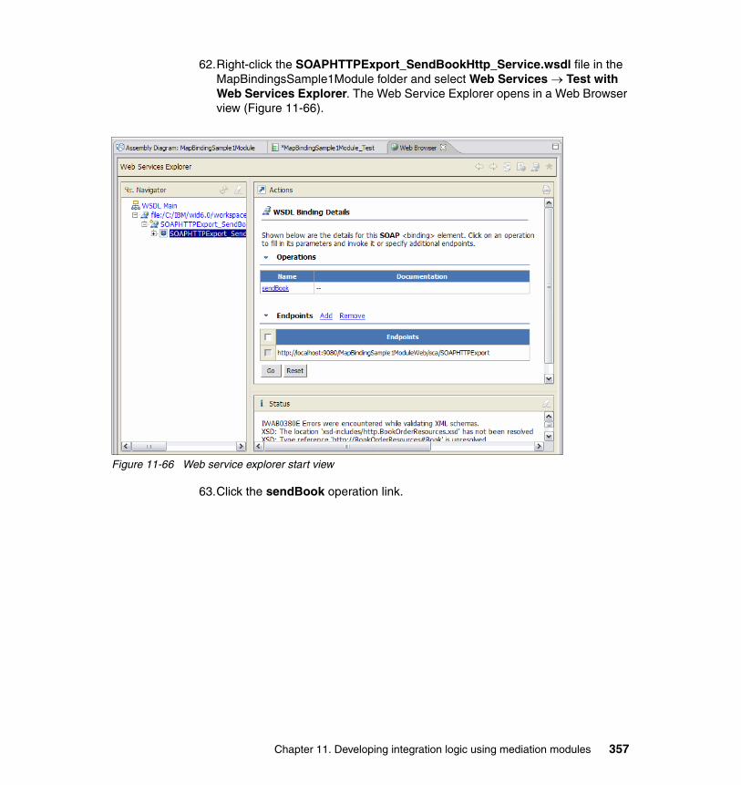
62.Right-click the SOAPHTTPExport_SendBookHttp_Service.wsdl file in the MapBindingsSample1Module folder and select Web Services → Test with Web Services Explorer. The Web Service Explorer opens in a Web Browser view (Figure 11-66).
Figure 11-66 Web service explorer start view
63.Click the sendBook operation link.
Chapter 11. Developing integration logic using mediation modules 357
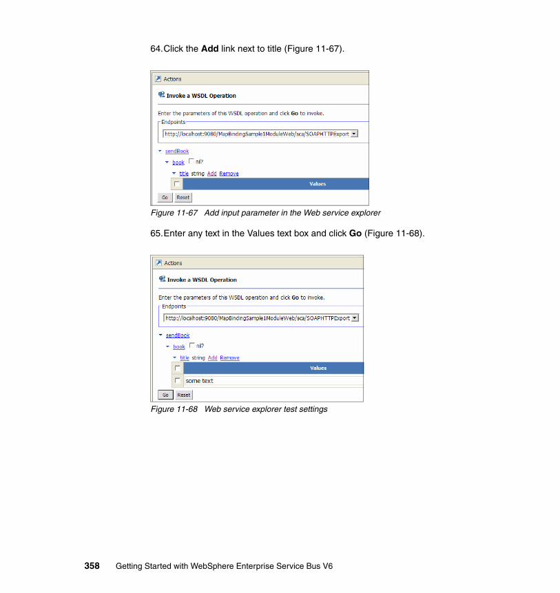
64.Click the Add link next to title (Figure 11-67).
Figure 11-67 Add input parameter in the Web service explorer
65.Enter any text in the Values text box and click Go (Figure 11-68).
Figure 11-68 Web service explorer test settings
358 Getting Started with WebSphere Enterprise Service Bus V6
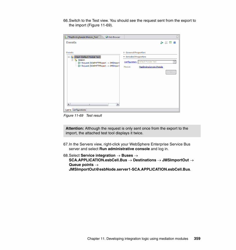
66.Switch to the Test view. You should see the request sent from the export to the import (Figure 11-69).
Figure 11-69 Test result
67.In the Servers view, right-click your WebSphere Enterprise Service Bus server and select Run administrative console and log in.
68.Select Service integration → Buses → SCA.APPLICATION.esbCell.Bus → Destinations → JMSImportOut → Queue points → [email protected].
Attention: Although the request is only sent once from the export to the import, the attached test tool displays it twice.
Chapter 11. Developing integration logic using mediation modules 359
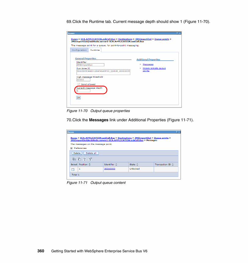
69.Click the Runtime tab. Current message depth should show 1 (Figure 11-70).
Figure 11-70 Output queue properties
70.Click the Messages link under Additional Properties (Figure 11-71).
Figure 11-71 Output queue content
360 Getting Started with WebSphere Enterprise Service Bus V6
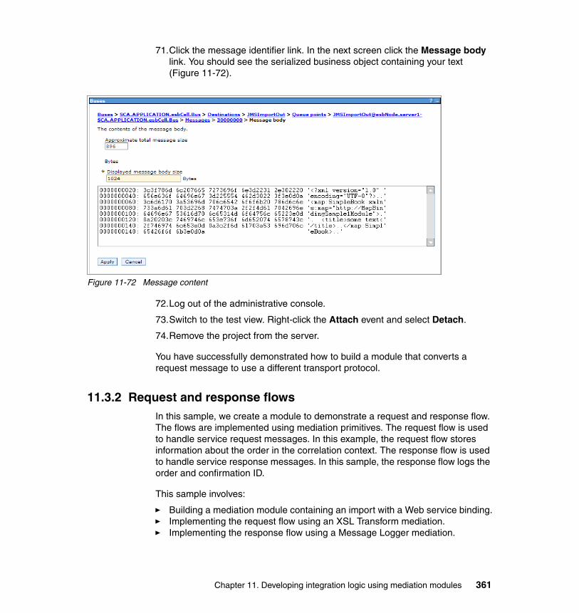
71.Click the message identifier link. In the next screen click the Message body link. You should see the serialized business object containing your text (Figure 11-72).
Figure 11-72 Message content
72.Log out of the administrative console.
73.Switch to the test view. Right-click the Attach event and select Detach.
74.Remove the project from the server.
You have successfully demonstrated how to build a module that converts a request message to use a different transport protocol.
11.3.2 Request and response flowsIn this sample, we create a module to demonstrate a request and response flow. The flows are implemented using mediation primitives. The request flow is used to handle service request messages. In this example, the request flow stores information about the order in the correlation context. The response flow is used to handle service response messages. In this sample, the response flow logs the order and confirmation ID.
This sample involves:
� Building a mediation module containing an import with a Web service binding.� Implementing the request flow using an XSL Transform mediation.� Implementing the response flow using a Message Logger mediation.
Chapter 11. Developing integration logic using mediation modules 361
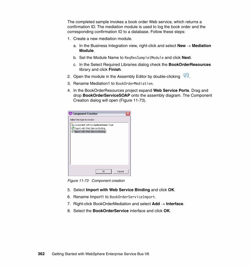
The completed sample invokes a book order Web service, which returns a confirmation ID. The mediation module is used to log the book order and the corresponding confirmation ID to a database. Follow these steps:
1. Create a new mediation module.
a. In the Business Integration view, right-click and select New → Mediation Module.
b. Set the Module Name to ReqResSample1Module and click Next.
c. In the Select Required Libraries dialog check the BookOrderResources library and click Finish.
2. Open the module in the Assembly Editor by double-clicking .
3. Rename Mediation1 to BookOrderMediation.
4. In the BookOrderResources project expand Web Service Ports. Drag and drop BookOrderServiceSOAP onto the assembly diagram. The Component Creation dialog will open (Figure 11-73).
Figure 11-73 Component creation
5. Select Import with Web Service Binding and click OK.
6. Rename Import1 to BookOrderServiceImport.
7. Right-click BookOrderMediation and select Add → Interface.
8. Select the BookOrderService interface and click OK.
362 Getting Started with WebSphere Enterprise Service Bus V6
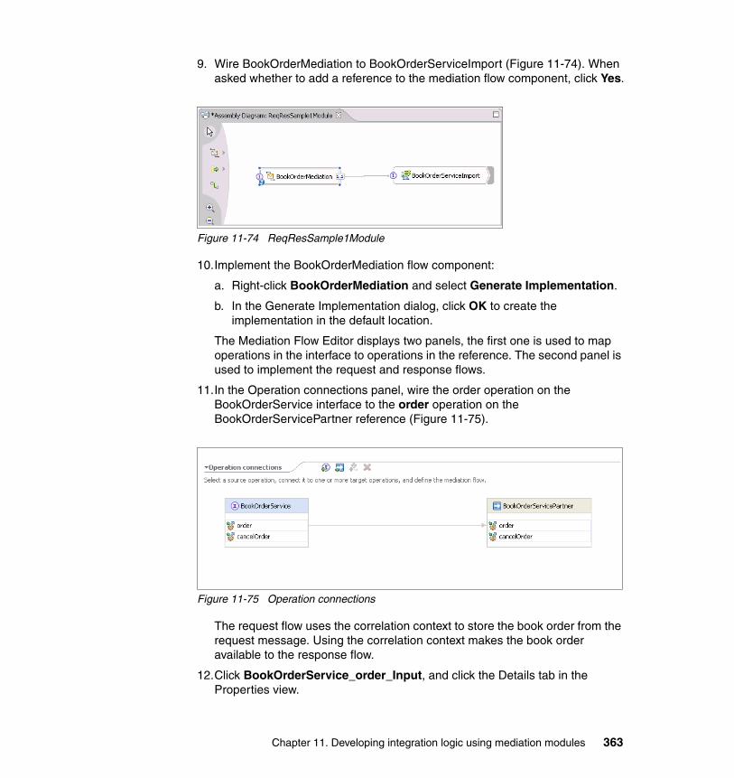
9. Wire BookOrderMediation to BookOrderServiceImport (Figure 11-74). When asked whether to add a reference to the mediation flow component, click Yes.
Figure 11-74 ReqResSample1Module
10.Implement the BookOrderMediation flow component:
a. Right-click BookOrderMediation and select Generate Implementation.
b. In the Generate Implementation dialog, click OK to create the implementation in the default location.
The Mediation Flow Editor displays two panels, the first one is used to map operations in the interface to operations in the reference. The second panel is used to implement the request and response flows.
11.In the Operation connections panel, wire the order operation on the BookOrderService interface to the order operation on the BookOrderServicePartner reference (Figure 11-75).
Figure 11-75 Operation connections
The request flow uses the correlation context to store the book order from the request message. Using the correlation context makes the book order available to the response flow.
12.Click BookOrderService_order_Input, and click the Details tab in the Properties view.
Chapter 11. Developing integration logic using mediation modules 363

13.Next to Correlation context, click Browse (Figure 11-76).
Figure 11-76 Correlation context browse
Choose what type of business object to store in the correlation context:
1. In the Data Type Selection dialog, choose the BookOrder data type and click OK (Figure 11-77).
Figure 11-77 Data type selection
2. Add an XSLTransform mediation primitive to the request flow by using .
364 Getting Started with WebSphere Enterprise Service Bus V6
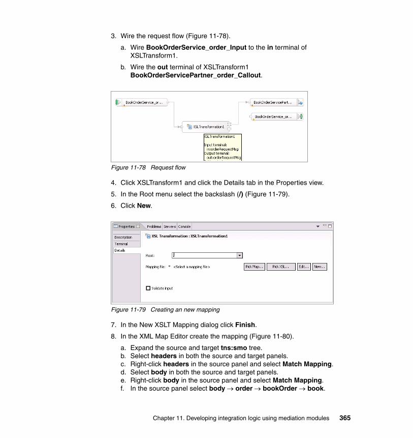
3. Wire the request flow (Figure 11-78).
a. Wire BookOrderService_order_Input to the in terminal of XSLTransform1.
b. Wire the out terminal of XSLTransform1 BookOrderServicePartner_order_Callout.
Figure 11-78 Request flow
4. Click XSLTransform1 and click the Details tab in the Properties view.
5. In the Root menu select the backslash (/) (Figure 11-79).
6. Click New.
Figure 11-79 Creating an new mapping
7. In the New XSLT Mapping dialog click Finish.
8. In the XML Map Editor create the mapping (Figure 11-80).
a. Expand the source and target tns:smo tree.b. Select headers in both the source and target panels. c. Right-click headers in the source panel and select Match Mapping.d. Select body in both the source and target panels.e. Right-click body in the source panel and select Match Mapping.f. In the source panel select body → order → bookOrder → book.
Chapter 11. Developing integration logic using mediation modules 365
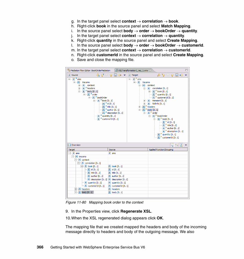
g. In the target panel select context → correlation → book.h. Right-click book in the source panel and select Match Mapping.i. In the source panel select body → order → bookOrder → quantity.j. In the target panel select context → correlation → quantity.k. Right-click quantity in the source panel and select Create Mapping.l. In the source panel select body → order → bookOrder → customerId.m. In the target panel select context → correlation → customerId.n. Right-click customerId in the source panel and select Create Mapping.o. Save and close the mapping file.
Figure 11-80 Mapping book order to the context
9. In the Properties view, click Regenerate XSL.
10.When the XSL regenerated dialog appears click OK.
The mapping file that we created mapped the headers and body of the incoming message directly to headers and body of the outgoing message. We also
366 Getting Started with WebSphere Enterprise Service Bus V6
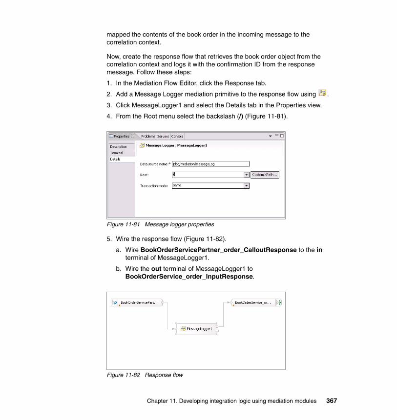
mapped the contents of the book order in the incoming message to the correlation context.
Now, create the response flow that retrieves the book order object from the correlation context and logs it with the confirmation ID from the response message. Follow these steps:
1. In the Mediation Flow Editor, click the Response tab.
2. Add a Message Logger mediation primitive to the response flow using .
3. Click MessageLogger1 and select the Details tab in the Properties view.
4. From the Root menu select the backslash (/) (Figure 11-81).
Figure 11-81 Message logger properties
5. Wire the response flow (Figure 11-82).
a. Wire BookOrderServicePartner_order_CalloutResponse to the in terminal of MessageLogger1.
b. Wire the out terminal of MessageLogger1 to BookOrderService_order_InputResponse.
Figure 11-82 Response flow
Chapter 11. Developing integration logic using mediation modules 367

6. Save the mediation flow and the module.
The module is now complete. The Integration Test Client is used to test the module. Follow these steps:
1. Deploy the module and the Web service to the server.
a. Switch to the Servers view.
b. Right-click your WebSphere Enterprise Service Bus server and select Add and remove projects.
c. Add BookOrderServiceEAR and ReqResSample1ModuleApp.
d. Click Finish.
2. Right-click ReqResSample1Module and select Test → Test Module.
3. Ensure BookOrderMediation is selected in the Component menu.
4. Select order from the Operation menu.
5. Enter values for the BookOrder and click Continue (Figure 11-83).
Figure 11-83 Integration test client
6. In the Deployment Location dialog select the WebSphere Enterprise Service Bus server and click Finish.
368 Getting Started with WebSphere Enterprise Service Bus V6
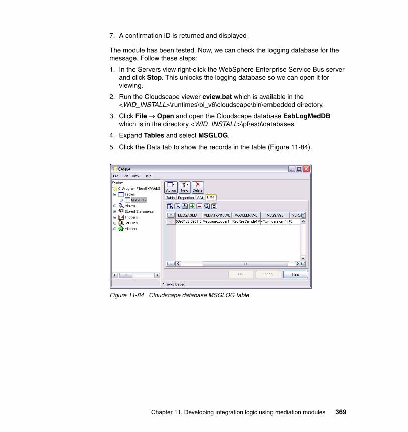
7. A confirmation ID is returned and displayed
The module has been tested. Now, we can check the logging database for the message. Follow these steps:
1. In the Servers view right-click the WebSphere Enterprise Service Bus server and click Stop. This unlocks the logging database so we can open it for viewing.
2. Run the Cloudscape viewer cview.bat which is available in the <WID_INSTALL>\runtimes\bi_v6\cloudscape\bin\embedded directory.
3. Click File → Open and open the Cloudscape database EsbLogMedDB which is in the directory <WID_INSTALL>\pf\esb\databases.
4. Expand Tables and select MSGLOG.
5. Click the Data tab to show the records in the table (Figure 11-84).
Figure 11-84 Cloudscape database MSGLOG table
Chapter 11. Developing integration logic using mediation modules 369
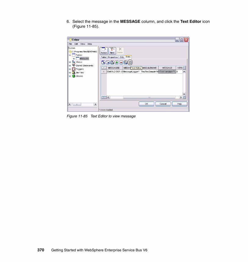
6. Select the message in the MESSAGE column, and click the Text Editor icon (Figure 11-85).
Figure 11-85 Text Editor to view message
370 Getting Started with WebSphere Enterprise Service Bus V6
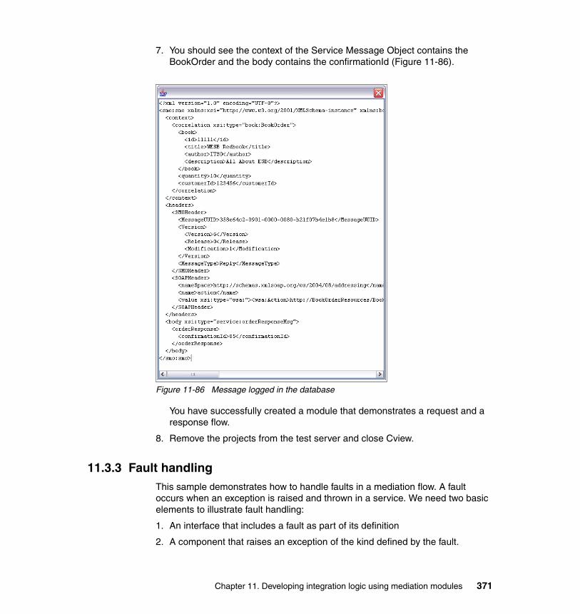
7. You should see the context of the Service Message Object contains the BookOrder and the body contains the confirmationId (Figure 11-86).
Figure 11-86 Message logged in the database
You have successfully created a module that demonstrates a request and a response flow.
8. Remove the projects from the test server and close Cview.
11.3.3 Fault handlingThis sample demonstrates how to handle faults in a mediation flow. A fault occurs when an exception is raised and thrown in a service. We need two basic elements to illustrate fault handling:
1. An interface that includes a fault as part of its definition
2. A component that raises an exception of the kind defined by the fault.
Chapter 11. Developing integration logic using mediation modules 371
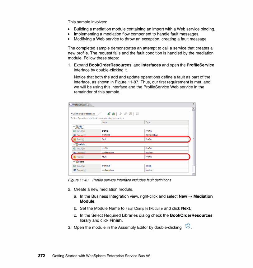
This sample involves:
� Building a mediation module containing an import with a Web service binding.� Implementing a mediation flow component to handle fault messages.� Modifying a Web service to throw an exception, creating a fault message.
The completed sample demonstrates an attempt to call a service that creates a new profile. The request fails and the fault condition is handled by the mediation module. Follow these steps:
1. Expand BookOrderResources, and Interfaces and open the ProfileService interface by double-clicking it.
Notice that both the add and update operations define a fault as part of the interface, as shown in Figure 11-87. Thus, our first requirement is met, and we will be using this interface and the ProfileService Web service in the remainder of this sample.
Figure 11-87 Profile service interface includes fault definitions
2. Create a new mediation module.
a. In the Business Integration view, right-click and select New → Mediation Module.
b. Set the Module Name to FaultSample1Module and click Next.
c. In the Select Required Libraries dialog check the BookOrderResources library and click Finish.
3. Open the module in the Assembly Editor by double-clicking .
372 Getting Started with WebSphere Enterprise Service Bus V6
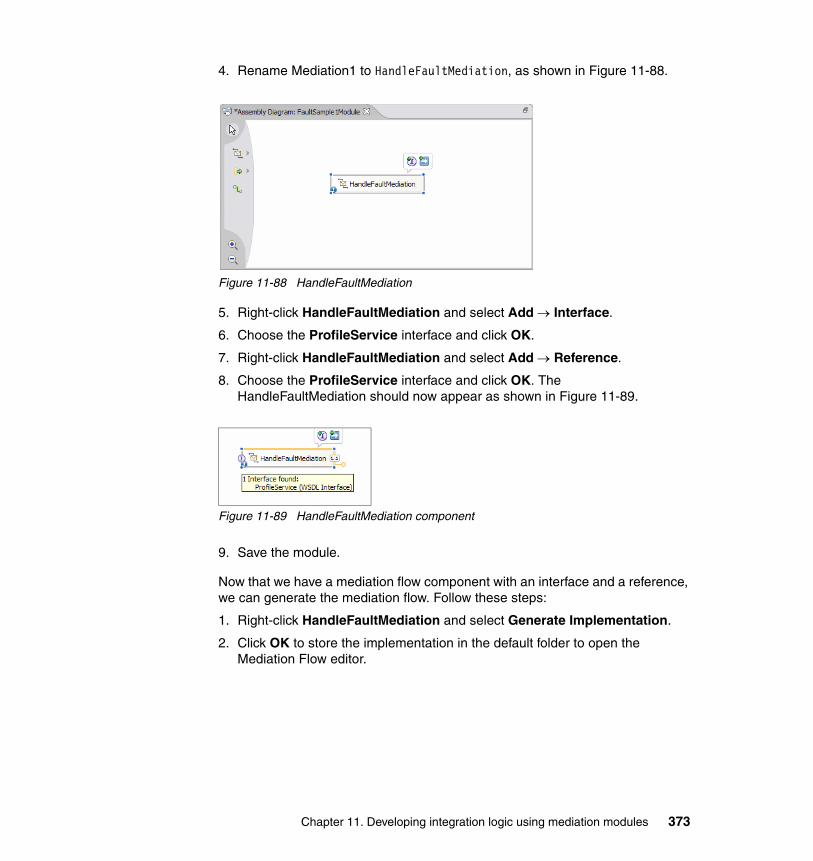
4. Rename Mediation1 to HandleFaultMediation, as shown in Figure 11-88.
Figure 11-88 HandleFaultMediation
5. Right-click HandleFaultMediation and select Add → Interface.
6. Choose the ProfileService interface and click OK.
7. Right-click HandleFaultMediation and select Add → Reference.
8. Choose the ProfileService interface and click OK. The HandleFaultMediation should now appear as shown in Figure 11-89.
Figure 11-89 HandleFaultMediation component
9. Save the module.
Now that we have a mediation flow component with an interface and a reference, we can generate the mediation flow. Follow these steps:
1. Right-click HandleFaultMediation and select Generate Implementation.
2. Click OK to store the implementation in the default folder to open the Mediation Flow editor.
Chapter 11. Developing integration logic using mediation modules 373
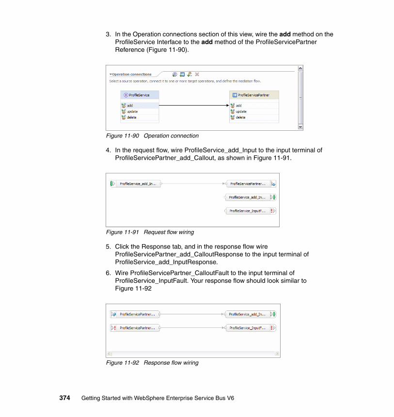
3. In the Operation connections section of this view, wire the add method on the ProfileService Interface to the add method of the ProfileServicePartner Reference (Figure 11-90).
Figure 11-90 Operation connection
4. In the request flow, wire ProfileService_add_Input to the input terminal of ProfileServicePartner_add_Callout, as shown in Figure 11-91.
Figure 11-91 Request flow wiring
5. Click the Response tab, and in the response flow wire ProfileServicePartner_add_CalloutResponse to the input terminal of ProfileService_add_InputResponse.
6. Wire ProfileServicePartner_CalloutFault to the input terminal of ProfileService_InputFault. Your response flow should look similar to Figure 11-92
Figure 11-92 Response flow wiring
374 Getting Started with WebSphere Enterprise Service Bus V6

7. Save the mediation flow.
8. Expand the BookOrderResources library in the Business Integration view, and the Web Service Ports.
9. Drag and drop the ProfileServiceSOAP from the Business Integration view into the assembly diagram of the FaultSample1Module module.
10.This opens the Component Creation window. Select Import with Web Service Binding and click OK.
Figure 11-93 Component creation selection
11.Select the newly created import Import1 in the assembly diagram and rename it to ProfileServiceImport.
12.Wire the WSDL reference from the HandleFaultMediation to the interface on ProfileServiceImport. Your assembly diagram should match Figure 11-94.
Figure 11-94 FaultSample1Module assembly diagram
13.Save the mediation module.
Chapter 11. Developing integration logic using mediation modules 375
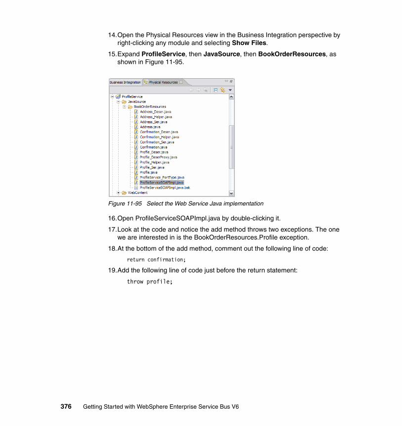
14.Open the Physical Resources view in the Business Integration perspective by right-clicking any module and selecting Show Files.
15.Expand ProfileService, then JavaSource, then BookOrderResources, as shown in Figure 11-95.
Figure 11-95 Select the Web Service Java implementation
16.Open ProfileServiceSOAPImpl.java by double-clicking it.
17.Look at the code and notice the add method throws two exceptions. The one we are interested in is the BookOrderResources.Profile exception.
18.At the bottom of the add method, comment out the following line of code:
return confirmation;
19.Add the following line of code just before the return statement:
throw profile;
376 Getting Started with WebSphere Enterprise Service Bus V6

20.Make sure the code matches that shown in Example 11-5.
Example 11-5 add method of ProfileServiceSOAPImpl
public BookOrderResources.Confirmation add(BookOrderResources.Profile profile) throws java.rmi.RemoteException, BookOrderResources.Profile { String id = Integer.toString(new Random().nextInt(100)); while (profiles.containsKey(id)) { id = Integer.toString(new Random().nextInt(100)); } profiles.put(id, profile); Confirmation confirmation = new Confirmation(); confirmation.setId(id); throw profile; //return confirmation; }
21.Save the updated Java class.
We are now ready to test the mediation module. We use the Integration Test Client to perform the test. Follow these steps:
1. Start your WebSphere Enterprise Service Bus server.
2. Deploy the module and the Web service to the server.
a. Switch to the Servers view.
b. Right-click your WebSphere Enterprise Service Bus server and select Add and remove projects.
c. Add ProfileServiceEAR and FaultSample1ModuleApp.
d. Click Finish.
3. In the Business Integration view, right-click FaultSample1Module and select Test → Test Module.
4. Set the Component to HandleFaultMediation.
5. Select the add operation from the Operation menu.
Chapter 11. Developing integration logic using mediation modules 377
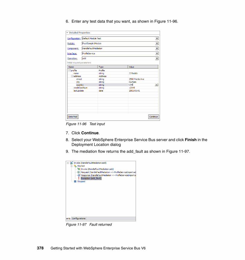
6. Enter any test data that you want, as shown in Figure 11-96.
Figure 11-96 Test input
7. Click Continue.
8. Select your WebSphere Enterprise Service Bus server and click Finish in the Deployment Location dialog
9. The mediation flow returns the add_fault as shown in Figure 11-97.
Figure 11-97 Fault returned
378 Getting Started with WebSphere Enterprise Service Bus V6
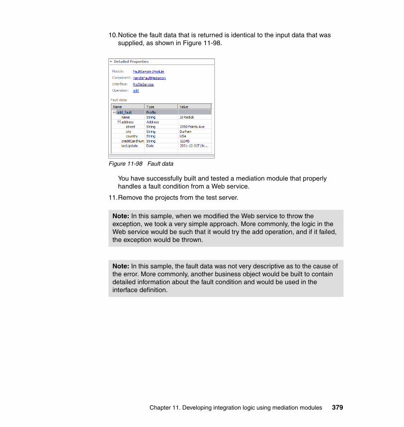
10.Notice the fault data that is returned is identical to the input data that was supplied, as shown in Figure 11-98.
Figure 11-98 Fault data
You have successfully built and tested a mediation module that properly handles a fault condition from a Web service.
11.Remove the projects from the test server.
Note: In this sample, when we modified the Web service to throw the exception, we took a very simple approach. More commonly, the logic in the Web service would be such that it would try the add operation, and if it failed, the exception would be thrown.
Note: In this sample, the fault data was not very descriptive as to the cause of the error. More commonly, another business object would be built to contain detailed information about the fault condition and would be used in the interface definition.
Chapter 11. Developing integration logic using mediation modules 379

380 Getting Started with WebSphere Enterprise Service Bus V6

Chapter 12. Developing mediation logic using mediation primitives
This chapter provides step-by-step instructions for using each of the mediation primitives that are provided by WebSphere Enterprise Service Bus, which are:
� XSL Transformation mediation primitive� Database Lookup mediation primitive� Message Filter mediation primitive� Message Logger mediation primitive� Stop mediation primitive� Fail mediation primitive� Custom mediation primitive
These development examples assume that you have configured your WebSphere Integration Developer workspace as described in Chapter 10, “Preparing for the development examples” on page 281.
You might find it useful to refer to Chapter 7, “WebSphere Integration Developer key concepts and common tasks” on page 159 for more detailed information about how to perform specific tasks in WebSphere Integration Developer.
You can import completed Project Interchange projects for each mediation primitive development example from the additional material that is supplied with this redbook in the \MediationPrimitives\Solutions directory.
12
© Copyright IBM Corp. 2006. All rights reserved. 381
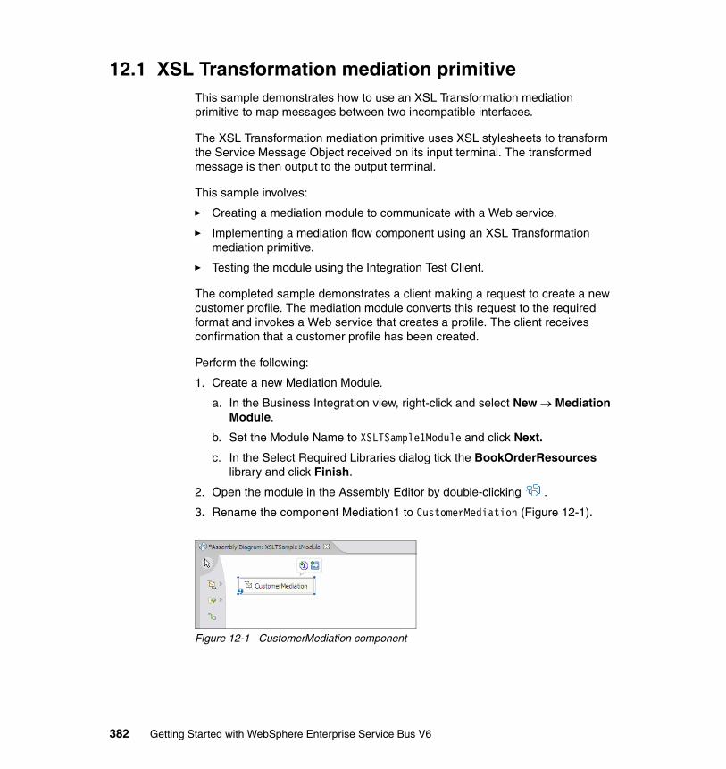
12.1 XSL Transformation mediation primitiveThis sample demonstrates how to use an XSL Transformation mediation primitive to map messages between two incompatible interfaces.
The XSL Transformation mediation primitive uses XSL stylesheets to transform the Service Message Object received on its input terminal. The transformed message is then output to the output terminal.
This sample involves:
� Creating a mediation module to communicate with a Web service.
� Implementing a mediation flow component using an XSL Transformation mediation primitive.
� Testing the module using the Integration Test Client.
The completed sample demonstrates a client making a request to create a new customer profile. The mediation module converts this request to the required format and invokes a Web service that creates a profile. The client receives confirmation that a customer profile has been created.
Perform the following:
1. Create a new Mediation Module.
a. In the Business Integration view, right-click and select New → Mediation Module.
b. Set the Module Name to XSLTSample1Module and click Next.
c. In the Select Required Libraries dialog tick the BookOrderResources library and click Finish.
2. Open the module in the Assembly Editor by double-clicking .
3. Rename the component Mediation1 to CustomerMediation (Figure 12-1).
Figure 12-1 CustomerMediation component
382 Getting Started with WebSphere Enterprise Service Bus V6
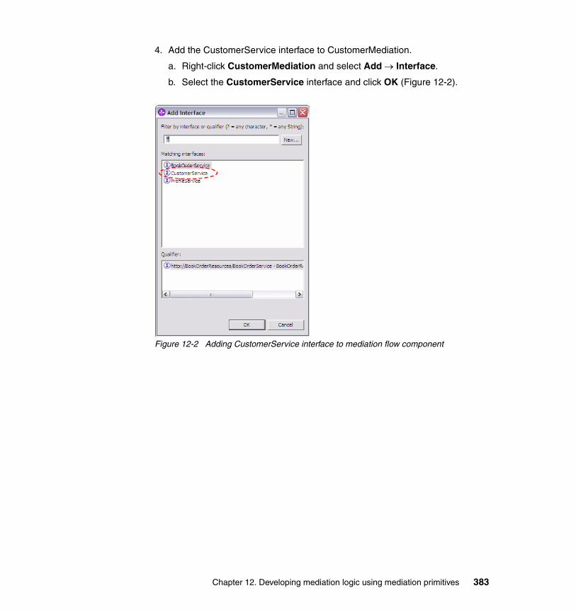
4. Add the CustomerService interface to CustomerMediation.
a. Right-click CustomerMediation and select Add → Interface.
b. Select the CustomerService interface and click OK (Figure 12-2).
Figure 12-2 Adding CustomerService interface to mediation flow component
Chapter 12. Developing mediation logic using mediation primitives 383
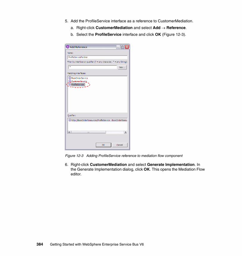
5. Add the ProfileService interface as a reference to CustomerMediation.
a. Right-click CustomerMediation and select Add → Reference.
b. Select the ProfileService interface and click OK (Figure 12-3).
Figure 12-3 Adding ProfileService reference to mediation flow component
6. Right-click CustomerMediation and select Generate Implementation. In the Generate Implementation dialog, click OK. This opens the Mediation Flow editor.
384 Getting Started with WebSphere Enterprise Service Bus V6
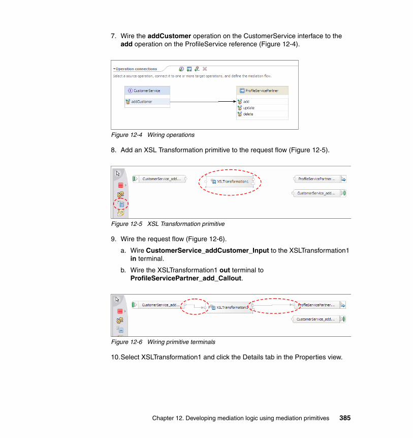
7. Wire the addCustomer operation on the CustomerService interface to the add operation on the ProfileService reference (Figure 12-4).
Figure 12-4 Wiring operations
8. Add an XSL Transformation primitive to the request flow (Figure 12-5).
Figure 12-5 XSL Transformation primitive
9. Wire the request flow (Figure 12-6).
a. Wire CustomerService_addCustomer_Input to the XSLTransformation1 in terminal.
b. Wire the XSLTransformation1 out terminal to ProfileServicePartner_add_Callout.
Figure 12-6 Wiring primitive terminals
10.Select XSLTransformation1 and click the Details tab in the Properties view.
Chapter 12. Developing mediation logic using mediation primitives 385
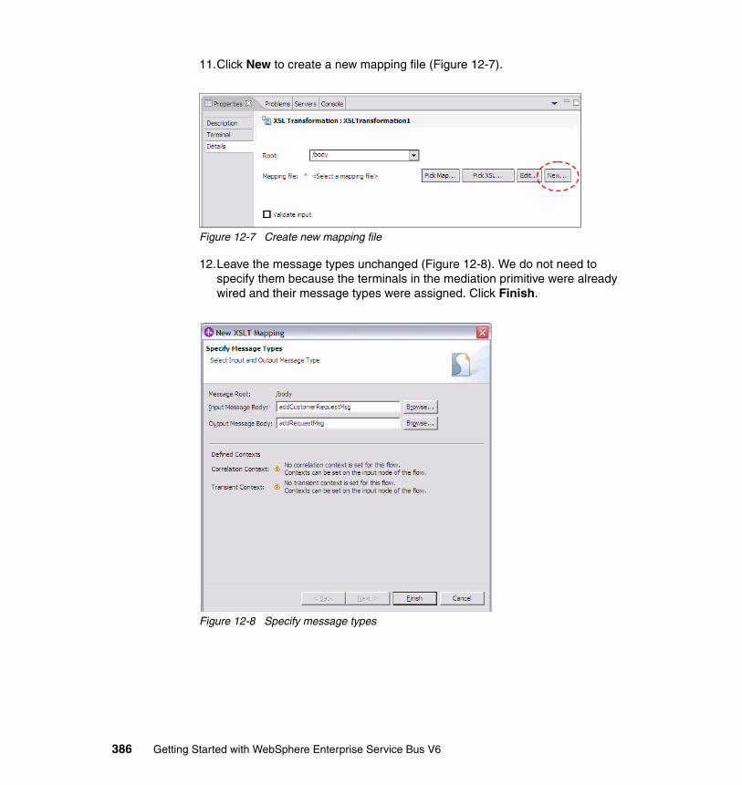
11.Click New to create a new mapping file (Figure 12-7).
Figure 12-7 Create new mapping file
12.Leave the message types unchanged (Figure 12-8). We do not need to specify them because the terminals in the mediation primitive were already wired and their message types were assigned. Click Finish.
Figure 12-8 Specify message types
386 Getting Started with WebSphere Enterprise Service Bus V6
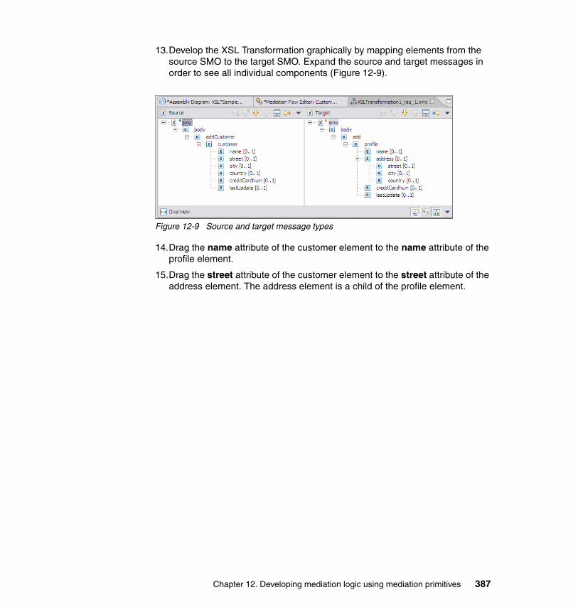
13.Develop the XSL Transformation graphically by mapping elements from the source SMO to the target SMO. Expand the source and target messages in order to see all individual components (Figure 12-9).
Figure 12-9 Source and target message types
14.Drag the name attribute of the customer element to the name attribute of the profile element.
15.Drag the street attribute of the customer element to the street attribute of the address element. The address element is a child of the profile element.
Chapter 12. Developing mediation logic using mediation primitives 387
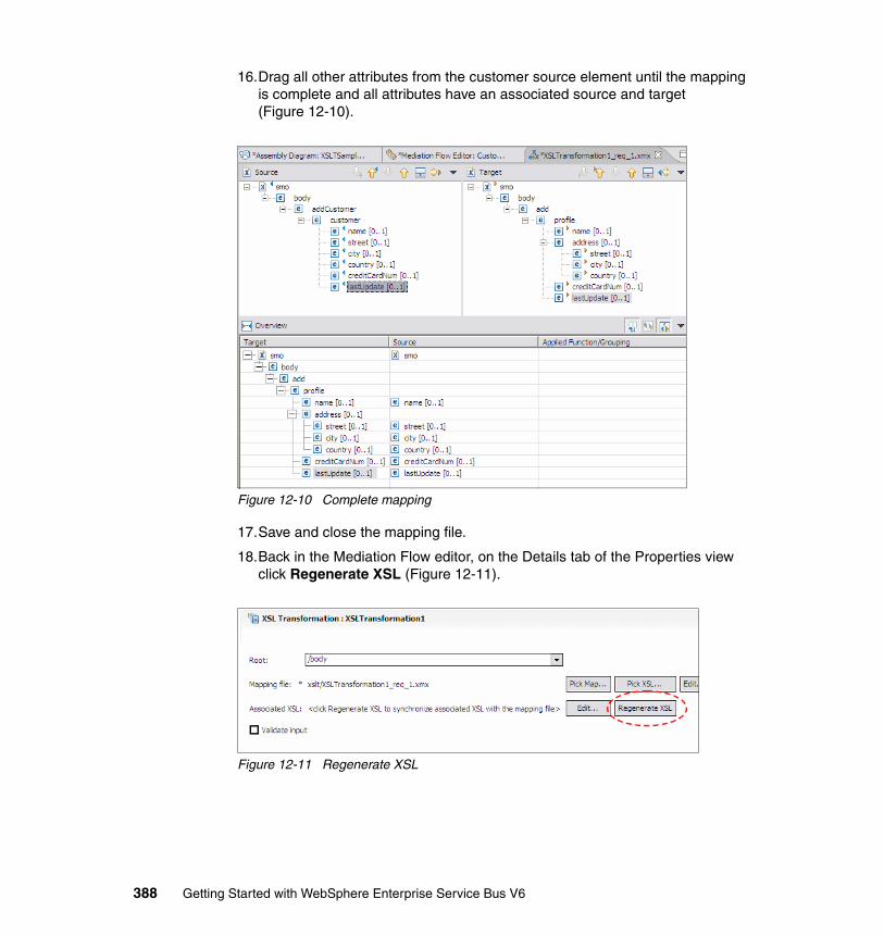
16.Drag all other attributes from the customer source element until the mapping is complete and all attributes have an associated source and target (Figure 12-10).
Figure 12-10 Complete mapping
17.Save and close the mapping file.
18.Back in the Mediation Flow editor, on the Details tab of the Properties view click Regenerate XSL (Figure 12-11).
Figure 12-11 Regenerate XSL
388 Getting Started with WebSphere Enterprise Service Bus V6
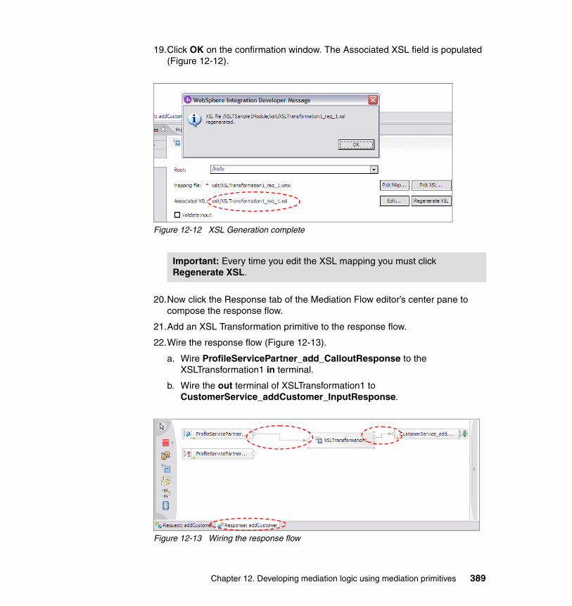
19.Click OK on the confirmation window. The Associated XSL field is populated (Figure 12-12).
Figure 12-12 XSL Generation complete
20.Now click the Response tab of the Mediation Flow editor’s center pane to compose the response flow.
21.Add an XSL Transformation primitive to the response flow.
22.Wire the response flow (Figure 12-13).
a. Wire ProfileServicePartner_add_CalloutResponse to the XSLTransformation1 in terminal.
b. Wire the out terminal of XSLTransformation1 to CustomerService_addCustomer_InputResponse.
Figure 12-13 Wiring the response flow
Important: Every time you edit the XSL mapping you must click Regenerate XSL.
Chapter 12. Developing mediation logic using mediation primitives 389
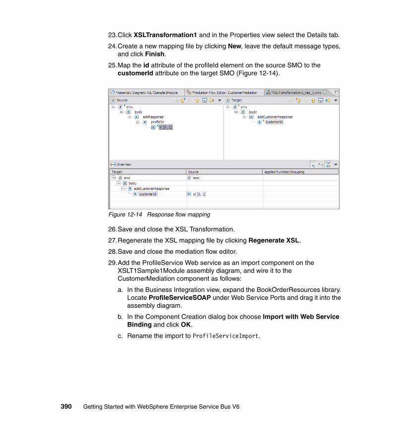
23.Click XSLTransformation1 and in the Properties view select the Details tab.
24.Create a new mapping file by clicking New, leave the default message types, and click Finish.
25.Map the id attribute of the profileId element on the source SMO to the customerId attribute on the target SMO (Figure 12-14).
Figure 12-14 Response flow mapping
26.Save and close the XSL Transformation.
27.Regenerate the XSL mapping file by clicking Regenerate XSL.
28.Save and close the mediation flow editor.
29.Add the ProfileService Web service as an import component on the XSLT1Sample1Module assembly diagram, and wire it to the CustomerMediation component as follows:
a. In the Business Integration view, expand the BookOrderResources library. Locate ProfileServiceSOAP under Web Service Ports and drag it into the assembly diagram.
b. In the Component Creation dialog box choose Import with Web Service Binding and click OK.
c. Rename the import to ProfileServiceImport.
390 Getting Started with WebSphere Enterprise Service Bus V6
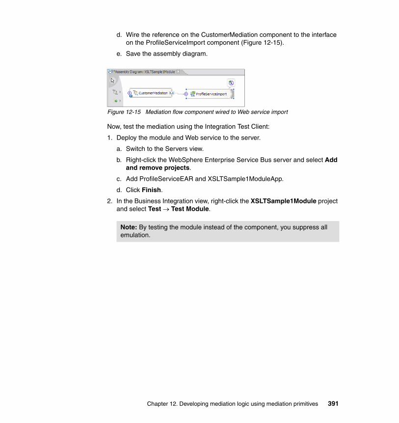
d. Wire the reference on the CustomerMediation component to the interface on the ProfileServiceImport component (Figure 12-15).
e. Save the assembly diagram.
Figure 12-15 Mediation flow component wired to Web service import
Now, test the mediation using the Integration Test Client:
1. Deploy the module and Web service to the server.
a. Switch to the Servers view.
b. Right-click the WebSphere Enterprise Service Bus server and select Add and remove projects.
c. Add ProfileServiceEAR and XSLTSample1ModuleApp.
d. Click Finish.
2. In the Business Integration view, right-click the XSLTSample1Module project and select Test → Test Module.
Note: By testing the module instead of the component, you suppress all emulation.
Chapter 12. Developing mediation logic using mediation primitives 391
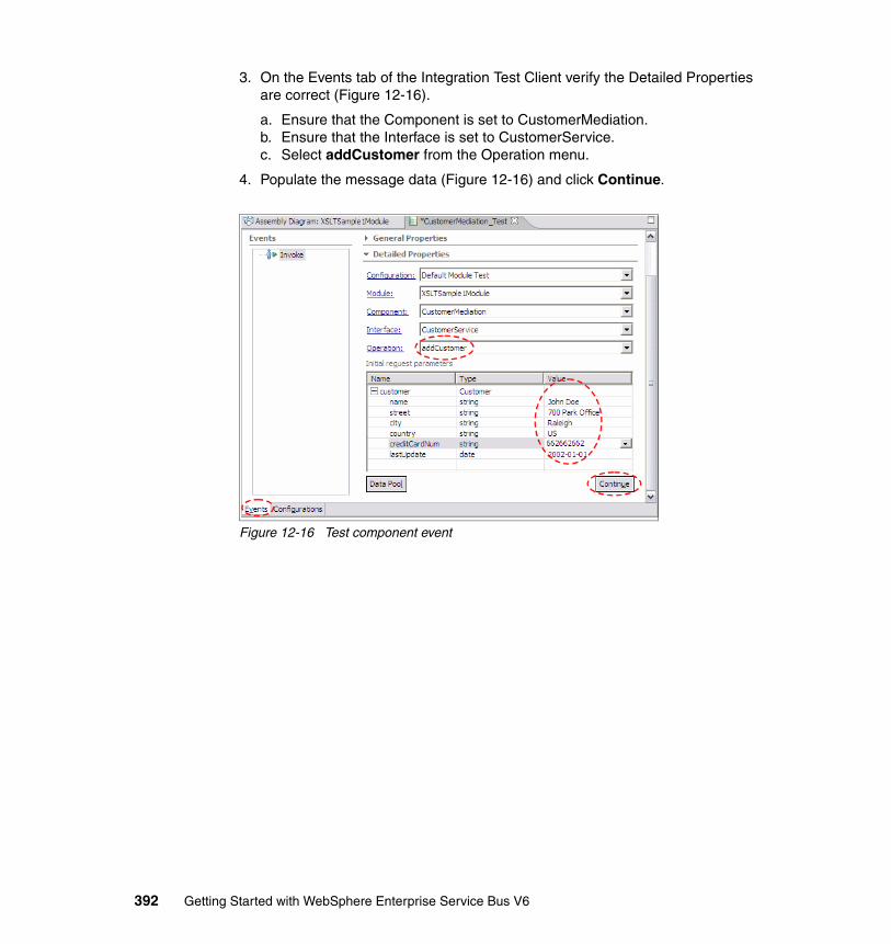
3. On the Events tab of the Integration Test Client verify the Detailed Properties are correct (Figure 12-16).
a. Ensure that the Component is set to CustomerMediation.b. Ensure that the Interface is set to CustomerService.c. Select addCustomer from the Operation menu.
4. Populate the message data (Figure 12-16) and click Continue.
Figure 12-16 Test component event
392 Getting Started with WebSphere Enterprise Service Bus V6
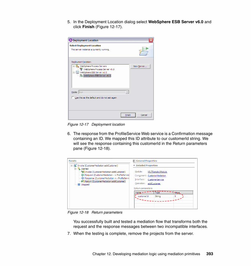
5. In the Deployment Location dialog select WebSphere ESB Server v6.0 and click Finish (Figure 12-17).
Figure 12-17 Deployment location
6. The response from the ProfileService Web service is a Confirmation message containing an ID. We mapped this ID attribute to our customerId string. We will see the response containing this customerId in the Return parameters pane (Figure 12-18).
Figure 12-18 Return parameters
You successfully built and tested a mediation flow that transforms both the request and the response messages between two incompatible interfaces.
7. When the testing is complete, remove the projects from the server.
Chapter 12. Developing mediation logic using mediation primitives 393

12.2 Database Lookup mediation primitiveThis sample demonstrates how to use a Database Lookup mediation primitive to update a message with a value from a database.
The Database Lookup mediation primitive is used to search for values in a database. It takes a key which will be part of the Service Message Object and searches for that key in a database. If the key is found, then a value that is associated with it is returned, and this can then be used to update the Service Message Object before forwarding it on.
This sample involves:
� Creating a Cloudscape database containing keys and values.
� Building a mediation module containing an import with a Web service binding.
� Implementing a mediation flow component using a Database Lookup mediation primitive.
� Testing the module using the Integration Test Client.
The completed sample invokes a book order Web service, which returns a confirmation ID. The mediation module is used to add a country to the description of the book, contained in the book order, before forwarding it to the Web service.
Perform the following:
1. Create a new mediation module.
a. In the Business Integration view, right-click and select New → Mediation Module.
b. Set the Module Name to DatabaseLookupSample1Module and click Next.
c. In the Select Required Libraries dialog check the BookOrderResources library and click Finish.
2. Open the module in the Assembly Editor by double-clicking .
394 Getting Started with WebSphere Enterprise Service Bus V6
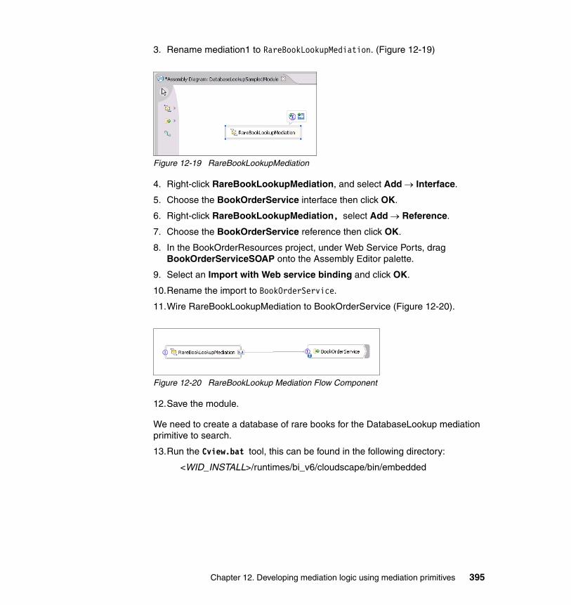
3. Rename mediation1 to RareBookLookupMediation. (Figure 12-19)
Figure 12-19 RareBookLookupMediation
4. Right-click RareBookLookupMediation, and select Add → Interface.
5. Choose the BookOrderService interface then click OK.
6. Right-click RareBookLookupMediation, select Add → Reference.
7. Choose the BookOrderService reference then click OK.
8. In the BookOrderResources project, under Web Service Ports, drag BookOrderServiceSOAP onto the Assembly Editor palette.
9. Select an Import with Web service binding and click OK.
10.Rename the import to BookOrderService.
11.Wire RareBookLookupMediation to BookOrderService (Figure 12-20).
Figure 12-20 RareBookLookup Mediation Flow Component
12.Save the module.
We need to create a database of rare books for the DatabaseLookup mediation primitive to search.
13.Run the Cview.bat tool, this can be found in the following directory:
<WID_INSTALL>/runtimes/bi_v6/cloudscape/bin/embedded
Chapter 12. Developing mediation logic using mediation primitives 395
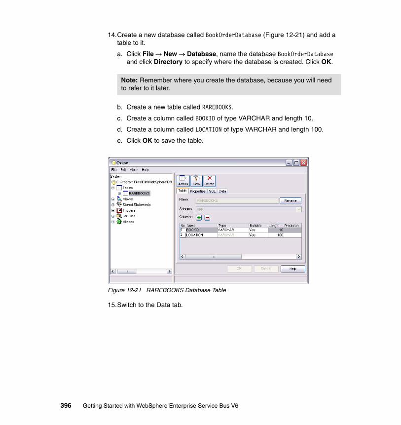
14.Create a new database called BookOrderDatabase (Figure 12-21) and add a table to it.
a. Click File → New → Database, name the database BookOrderDatabase and click Directory to specify where the database is created. Click OK.
b. Create a new table called RAREBOOKS.
c. Create a column called BOOKID of type VARCHAR and length 10.
d. Create a column called LOCATION of type VARCHAR and length 100.
e. Click OK to save the table.
Figure 12-21 RAREBOOKS Database Table
15.Switch to the Data tab.
Note: Remember where you create the database, because you will need to refer to it later.
396 Getting Started with WebSphere Enterprise Service Bus V6
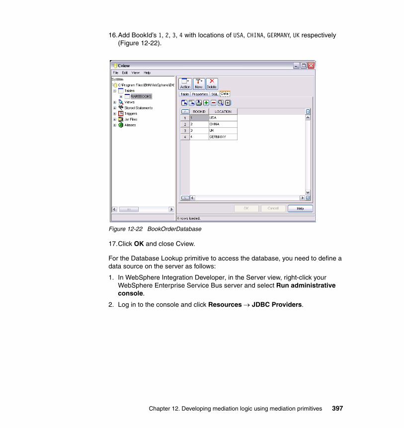
16.Add BookId’s 1, 2, 3, 4 with locations of USA, CHINA, GERMANY, UK respectively (Figure 12-22).
Figure 12-22 BookOrderDatabase
17.Click OK and close Cview.
For the Database Lookup primitive to access the database, you need to define a data source on the server as follows:
1. In WebSphere Integration Developer, in the Server view, right-click your WebSphere Enterprise Service Bus server and select Run administrative console.
2. Log in to the console and click Resources → JDBC Providers.
Chapter 12. Developing mediation logic using mediation primitives 397
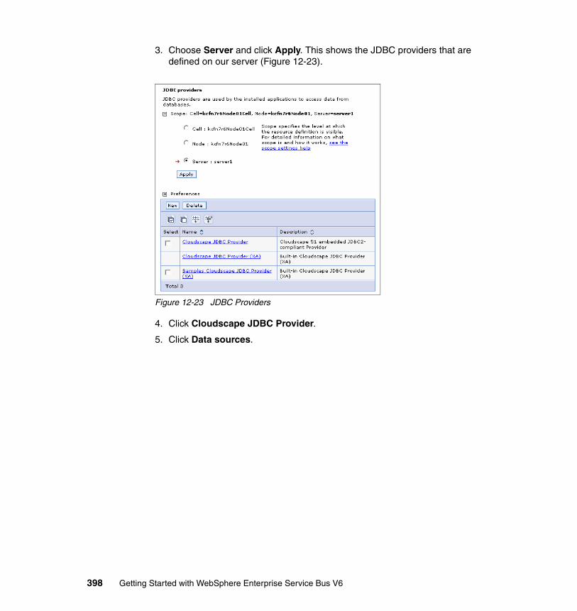
3. Choose Server and click Apply. This shows the JDBC providers that are defined on our server (Figure 12-23).
Figure 12-23 JDBC Providers
4. Click Cloudscape JDBC Provider.
5. Click Data sources.
398 Getting Started with WebSphere Enterprise Service Bus V6
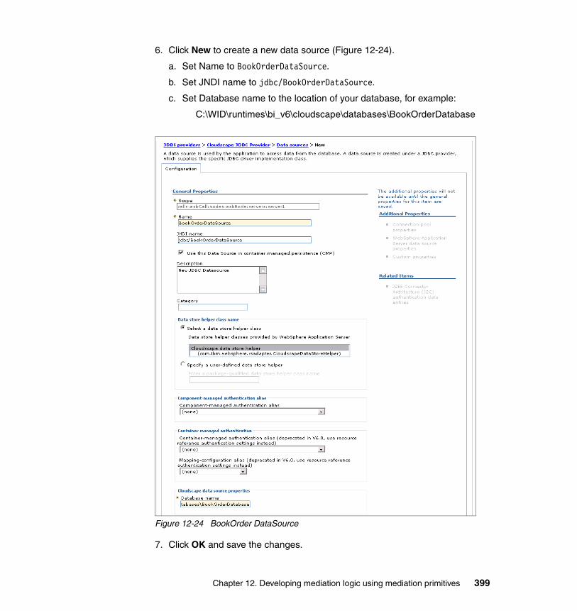
6. Click New to create a new data source (Figure 12-24).
a. Set Name to BookOrderDataSource.
b. Set JNDI name to jdbc/BookOrderDataSource.
c. Set Database name to the location of your database, for example:
C:\WID\runtimes\bi_v6\cloudscape\databases\BookOrderDatabase
Figure 12-24 BookOrder DataSource
7. Click OK and save the changes.
Chapter 12. Developing mediation logic using mediation primitives 399
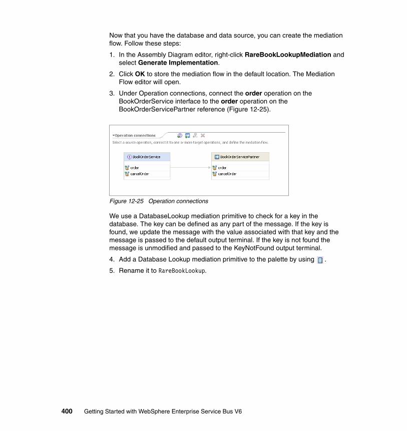
Now that you have the database and data source, you can create the mediation flow. Follow these steps:
1. In the Assembly Diagram editor, right-click RareBookLookupMediation and select Generate Implementation.
2. Click OK to store the mediation flow in the default location. The Mediation Flow editor will open.
3. Under Operation connections, connect the order operation on the BookOrderService interface to the order operation on the BookOrderServicePartner reference (Figure 12-25).
Figure 12-25 Operation connections
We use a DatabaseLookup mediation primitive to check for a key in the database. The key can be defined as any part of the message. If the key is found, we update the message with the value associated with that key and the message is passed to the default output terminal. If the key is not found the message is unmodified and passed to the KeyNotFound output terminal.
4. Add a Database Lookup mediation primitive to the palette by using .
5. Rename it to RareBookLookup.
400 Getting Started with WebSphere Enterprise Service Bus V6
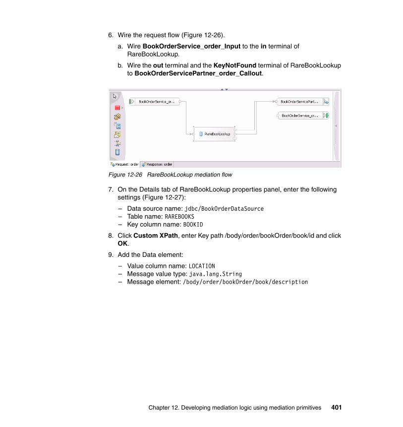
6. Wire the request flow (Figure 12-26).
a. Wire BookOrderService_order_Input to the in terminal of RareBookLookup.
b. Wire the out terminal and the KeyNotFound terminal of RareBookLookup to BookOrderServicePartner_order_Callout.
Figure 12-26 RareBookLookup mediation flow
7. On the Details tab of RareBookLookup properties panel, enter the following settings (Figure 12-27):
– Data source name: jdbc/BookOrderDataSource– Table name: RAREBOOKS– Key column name: BOOKID
8. Click Custom XPath, enter Key path /body/order/bookOrder/book/id and click OK.
9. Add the Data element:
– Value column name: LOCATION– Message value type: java.lang.String– Message element: /body/order/bookOrder/book/description
Chapter 12. Developing mediation logic using mediation primitives 401
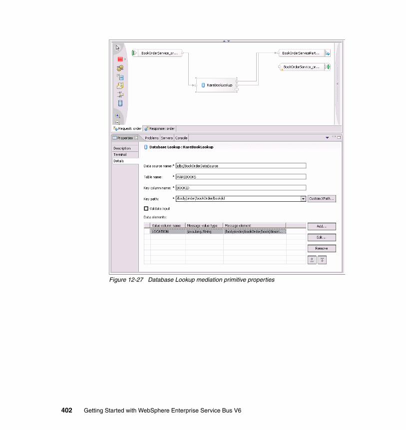
Figure 12-27 Database Lookup mediation primitive properties
402 Getting Started with WebSphere Enterprise Service Bus V6
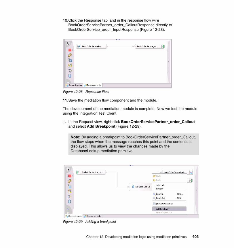
10.Click the Response tab, and in the response flow wire BookOrderServicePartner_order_CalloutResponse directly to BookOrderService_order_InputResponse (Figure 12-28).
Figure 12-28 Repsonse Flow
11.Save the mediation flow component and the module.
The development of the mediation module is complete. Now we test the module using the Integration Test Client.
1. In the Request view, right-click BookOrderServicePartner_order_Callout and select Add Breakpoint (Figure 12-29).
Figure 12-29 Adding a breakpoint
Note: By adding a breakpoint to BookOrderServicePartner_order_Callout, the flow stops when the message reaches this point and the contents is displayed. This allows us to view the changes made by the DatabaseLookup mediation primitive.
Chapter 12. Developing mediation logic using mediation primitives 403
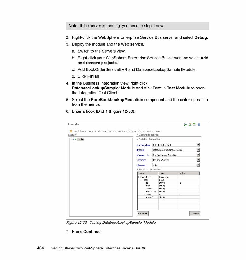
2. Right-click the WebSphere Enterprise Service Bus server and select Debug.
3. Deploy the module and the Web service.
a. Switch to the Servers view.
b. Right-click your WebSphere Enterprise Service Bus server and select Add and remove projects.
c. Add BookOrderServiceEAR and DatabaseLookupSample1Module.
d. Click Finish.
4. In the Business Integration view, right-click DatabaseLookupSample1Module and click Test → Test Module to open the Integration Test Client.
5. Select the RareBookLookupMediation component and the order operation from the menus.
6. Enter a book ID of 1 (Figure 12-30).
Figure 12-30 Testing DatabaseLookupSample1Module
7. Press Continue.
Note: If the server is running, you need to stop it now.
404 Getting Started with WebSphere Enterprise Service Bus V6

8. Select the WebSphere Enterprise Service Bus server and press Finish.
9. This opens the Debug perspective. In the variables view, expand the body of the message to check the value from the database has been added to the description (Figure 12-31).
Figure 12-31 Debugging DatabaseLookupSample1module
10.Click Resume to continue the flow. A confirmation message is returned.
Try using values 2, 3 and 4 for the book ID to see other values from the database.
Chapter 12. Developing mediation logic using mediation primitives 405
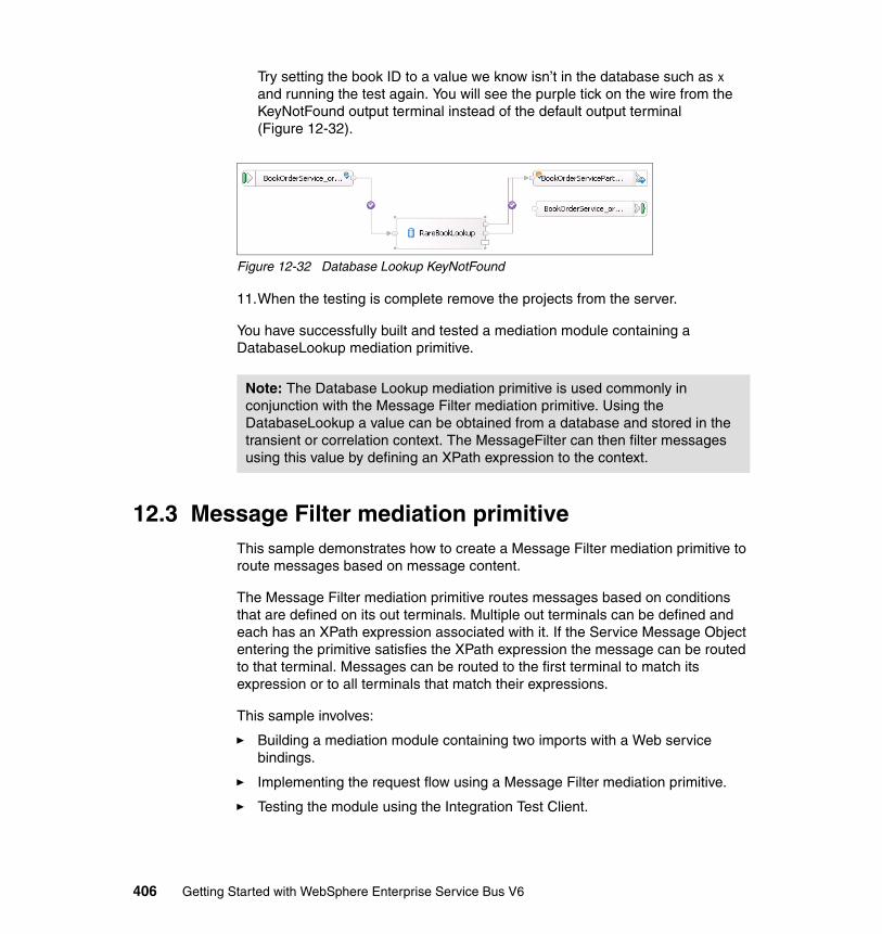
Try setting the book ID to a value we know isn’t in the database such as x and running the test again. You will see the purple tick on the wire from the KeyNotFound output terminal instead of the default output terminal (Figure 12-32).
Figure 12-32 Database Lookup KeyNotFound
11.When the testing is complete remove the projects from the server.
You have successfully built and tested a mediation module containing a DatabaseLookup mediation primitive.
12.3 Message Filter mediation primitiveThis sample demonstrates how to create a Message Filter mediation primitive to route messages based on message content.
The Message Filter mediation primitive routes messages based on conditions that are defined on its out terminals. Multiple out terminals can be defined and each has an XPath expression associated with it. If the Service Message Object entering the primitive satisfies the XPath expression the message can be routed to that terminal. Messages can be routed to the first terminal to match its expression or to all terminals that match their expressions.
This sample involves:
� Building a mediation module containing two imports with a Web service bindings.
� Implementing the request flow using a Message Filter mediation primitive.
� Testing the module using the Integration Test Client.
Note: The Database Lookup mediation primitive is used commonly in conjunction with the Message Filter mediation primitive. Using the DatabaseLookup a value can be obtained from a database and stored in the transient or correlation context. The MessageFilter can then filter messages using this value by defining an XPath expression to the context.
406 Getting Started with WebSphere Enterprise Service Bus V6
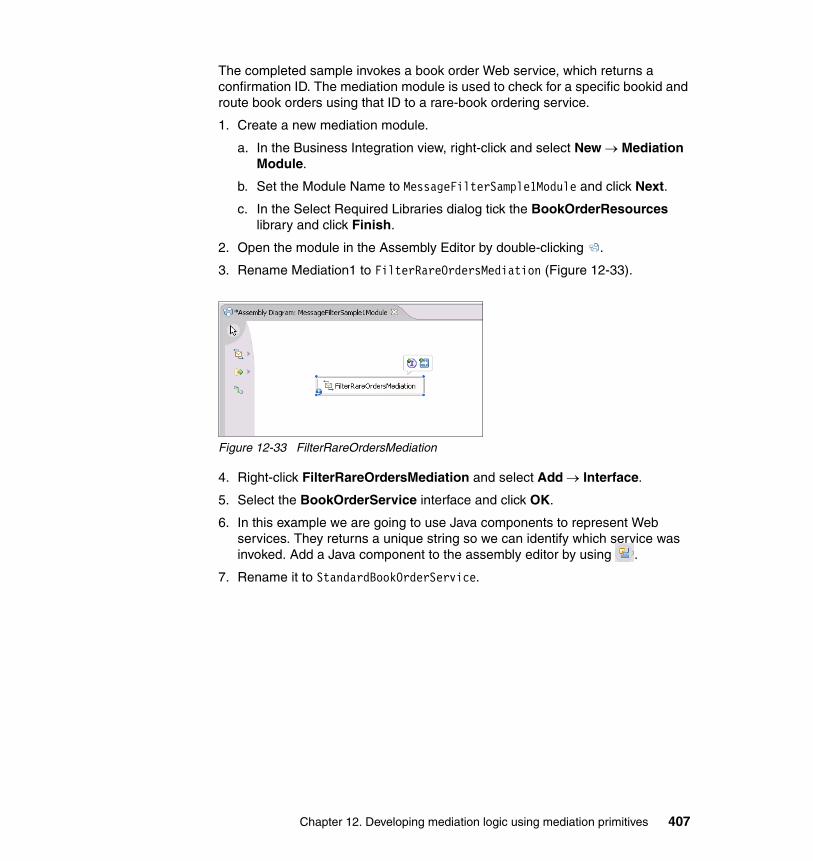
The completed sample invokes a book order Web service, which returns a confirmation ID. The mediation module is used to check for a specific bookid and route book orders using that ID to a rare-book ordering service.
1. Create a new mediation module.
a. In the Business Integration view, right-click and select New → Mediation Module.
b. Set the Module Name to MessageFilterSample1Module and click Next.
c. In the Select Required Libraries dialog tick the BookOrderResources library and click Finish.
2. Open the module in the Assembly Editor by double-clicking .
3. Rename Mediation1 to FilterRareOrdersMediation (Figure 12-33).
Figure 12-33 FilterRareOrdersMediation
4. Right-click FilterRareOrdersMediation and select Add → Interface.
5. Select the BookOrderService interface and click OK.
6. In this example we are going to use Java components to represent Web services. They returns a unique string so we can identify which service was invoked. Add a Java component to the assembly editor by using .
7. Rename it to StandardBookOrderService.
Chapter 12. Developing mediation logic using mediation primitives 407
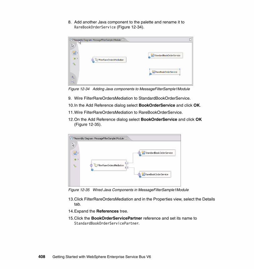
8. Add another Java component to the palette and rename it to RareBookOrderService (Figure 12-34).
Figure 12-34 Adding Java components to MessageFilterSample1Module
9. Wire FilterRareOrdersMediation to StandardBookOrderService.
10.In the Add Reference dialog select BookOrderService and click OK.
11.Wire FilterRareOrdersMediation to RareBookOrderService.
12.On the Add Reference dialog select BookOrderService and click OK (Figure 12-35).
Figure 12-35 Wired Java Components in MessageFilterSample1Module
13.Click FilterRareOrdersMediation and in the Properties view, select the Details tab.
14.Expand the References tree.
15.Click the BookOrderServicePartner reference and set its name to StandardBookOrderServicePartner.
408 Getting Started with WebSphere Enterprise Service Bus V6
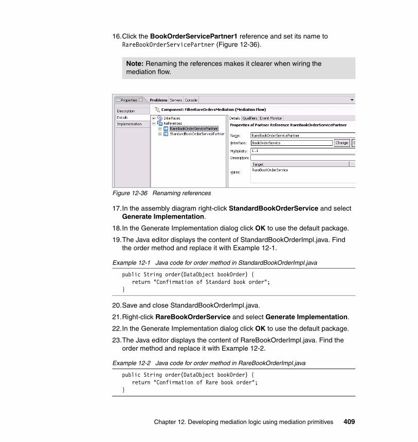
16.Click the BookOrderServicePartner1 reference and set its name to RareBookOrderServicePartner (Figure 12-36).
Figure 12-36 Renaming references
17.In the assembly diagram right-click StandardBookOrderService and select Generate Implementation.
18.In the Generate Implementation dialog click OK to use the default package.
19.The Java editor displays the content of StandardBookOrderImpl.java. Find the order method and replace it with Example 12-1.
Example 12-1 Java code for order method in StandardBookOrderImpl.java
public String order(DataObject bookOrder) {return "Confirmation of Standard book order";
}
20.Save and close StandardBookOrderImpl.java.
21.Right-click RareBookOrderService and select Generate Implementation.
22.In the Generate Implementation dialog click OK to use the default package.
23.The Java editor displays the content of RareBookOrderImpl.java. Find the order method and replace it with Example 12-2.
Example 12-2 Java code for order method in RareBookOrderImpl.java
public String order(DataObject bookOrder) {return "Confirmation of Rare book order";
}
Note: Renaming the references makes it clearer when wiring the mediation flow.
Chapter 12. Developing mediation logic using mediation primitives 409
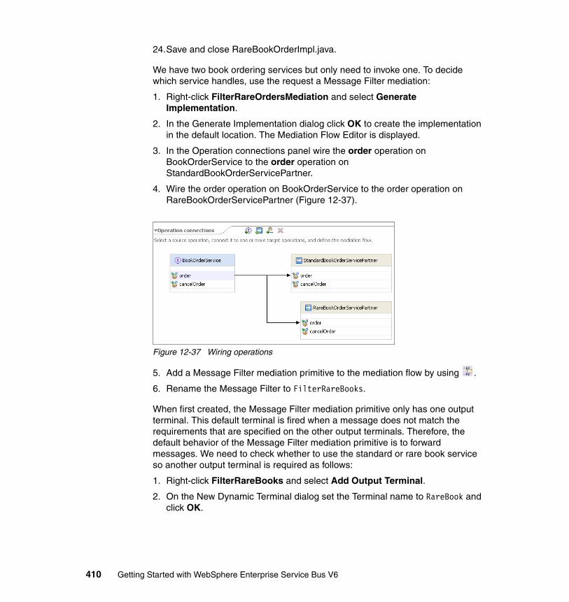
24.Save and close RareBookOrderImpl.java.
We have two book ordering services but only need to invoke one. To decide which service handles, use the request a Message Filter mediation:
1. Right-click FilterRareOrdersMediation and select Generate Implementation.
2. In the Generate Implementation dialog click OK to create the implementation in the default location. The Mediation Flow Editor is displayed.
3. In the Operation connections panel wire the order operation on BookOrderService to the order operation on StandardBookOrderServicePartner.
4. Wire the order operation on BookOrderService to the order operation on RareBookOrderServicePartner (Figure 12-37).
Figure 12-37 Wiring operations
5. Add a Message Filter mediation primitive to the mediation flow by using .
6. Rename the Message Filter to FilterRareBooks.
When first created, the Message Filter mediation primitive only has one output terminal. This default terminal is fired when a message does not match the requirements that are specified on the other output terminals. Therefore, the default behavior of the Message Filter mediation primitive is to forward messages. We need to check whether to use the standard or rare book service so another output terminal is required as follows:
1. Right-click FilterRareBooks and select Add Output Terminal.
2. On the New Dynamic Terminal dialog set the Terminal name to RareBook and click OK.
410 Getting Started with WebSphere Enterprise Service Bus V6
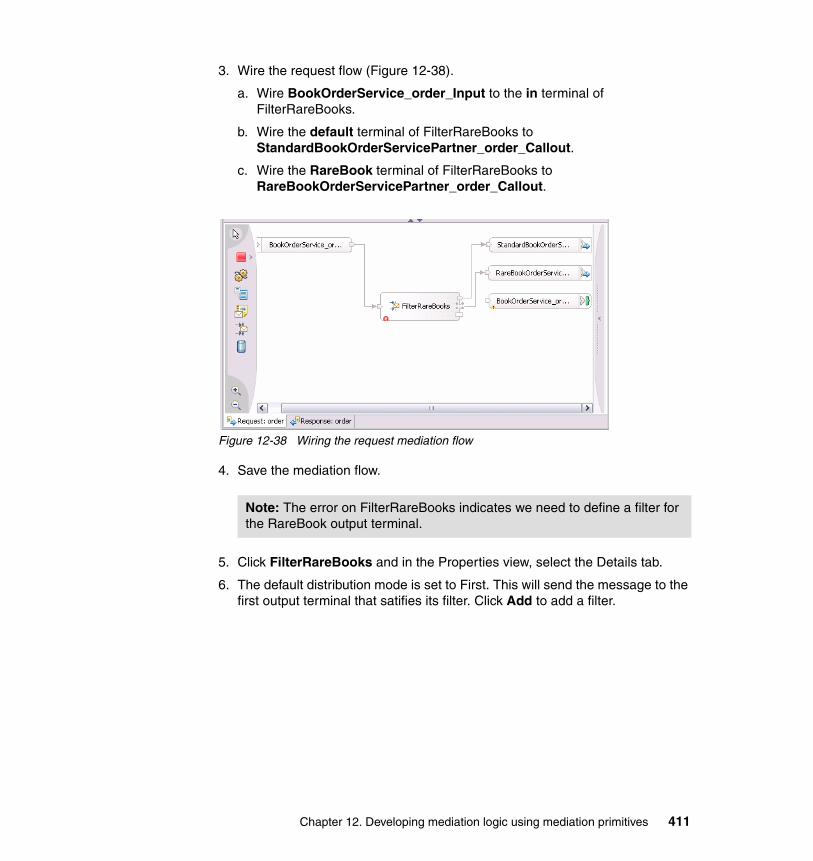
3. Wire the request flow (Figure 12-38).
a. Wire BookOrderService_order_Input to the in terminal of FilterRareBooks.
b. Wire the default terminal of FilterRareBooks to StandardBookOrderServicePartner_order_Callout.
c. Wire the RareBook terminal of FilterRareBooks to RareBookOrderServicePartner_order_Callout.
Figure 12-38 Wiring the request mediation flow
4. Save the mediation flow.
5. Click FilterRareBooks and in the Properties view, select the Details tab.
6. The default distribution mode is set to First. This will send the message to the first output terminal that satifies its filter. Click Add to add a filter.
Note: The error on FilterRareBooks indicates we need to define a filter for the RareBook output terminal.
Chapter 12. Developing mediation logic using mediation primitives 411
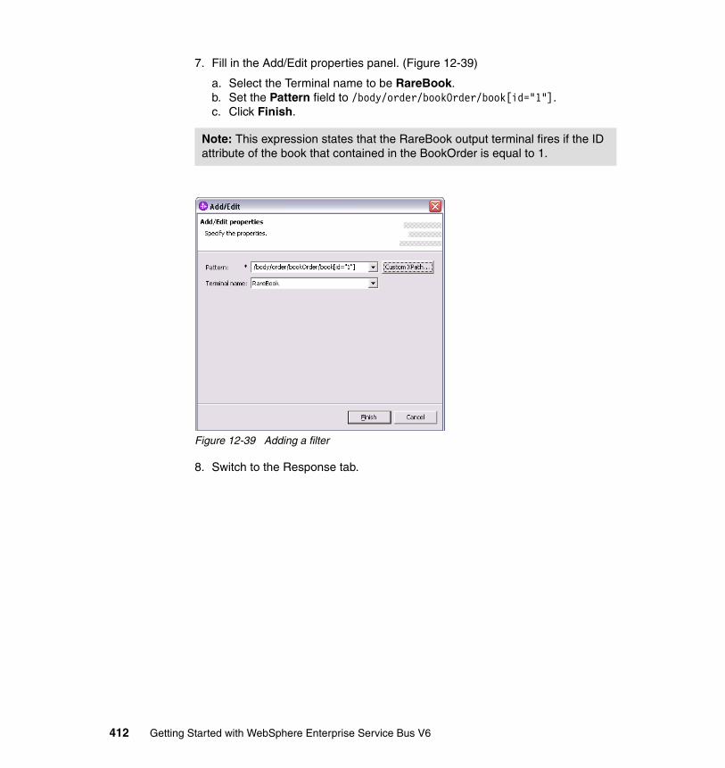
7. Fill in the Add/Edit properties panel. (Figure 12-39)
a. Select the Terminal name to be RareBook.b. Set the Pattern field to /body/order/bookOrder/book[id="1"].c. Click Finish.
Figure 12-39 Adding a filter
8. Switch to the Response tab.
Note: This expression states that the RareBook output terminal fires if the ID attribute of the book that contained in the BookOrder is equal to 1.
412 Getting Started with WebSphere Enterprise Service Bus V6
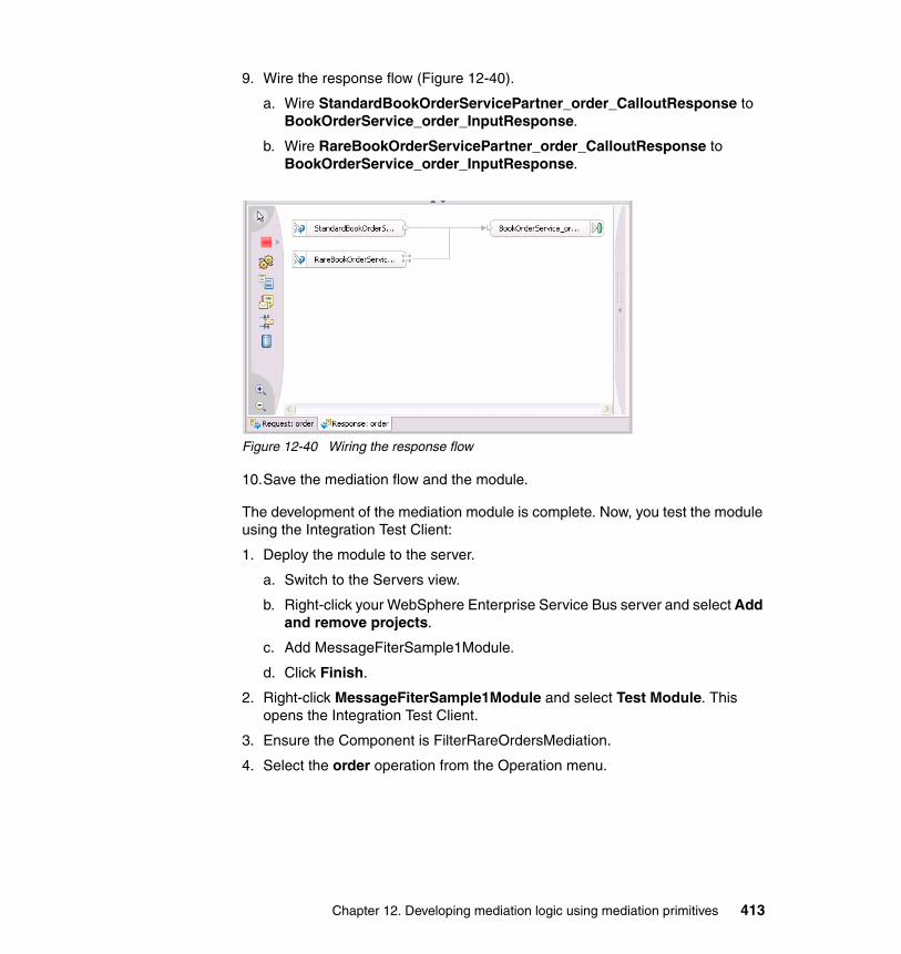
9. Wire the response flow (Figure 12-40).
a. Wire StandardBookOrderServicePartner_order_CalloutResponse to BookOrderService_order_InputResponse.
b. Wire RareBookOrderServicePartner_order_CalloutResponse to BookOrderService_order_InputResponse.
Figure 12-40 Wiring the response flow
10.Save the mediation flow and the module.
The development of the mediation module is complete. Now, you test the module using the Integration Test Client:
1. Deploy the module to the server.
a. Switch to the Servers view.
b. Right-click your WebSphere Enterprise Service Bus server and select Add and remove projects.
c. Add MessageFiterSample1Module.
d. Click Finish.
2. Right-click MessageFiterSample1Module and select Test Module. This opens the Integration Test Client.
3. Ensure the Component is FilterRareOrdersMediation.
4. Select the order operation from the Operation menu.
Chapter 12. Developing mediation logic using mediation primitives 413
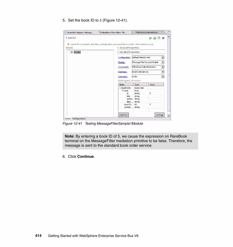
5. Set the book ID to 5 (Figure 12-41).
Figure 12-41 Testing MessageFilterSample1Module
6. Click Continue.
Note: By entering a book ID of 5, we cause the expression on RareBook terminal on the MessageFilter mediation primitive to be false. Therefore, the message is sent to the standard book order service.
414 Getting Started with WebSphere Enterprise Service Bus V6
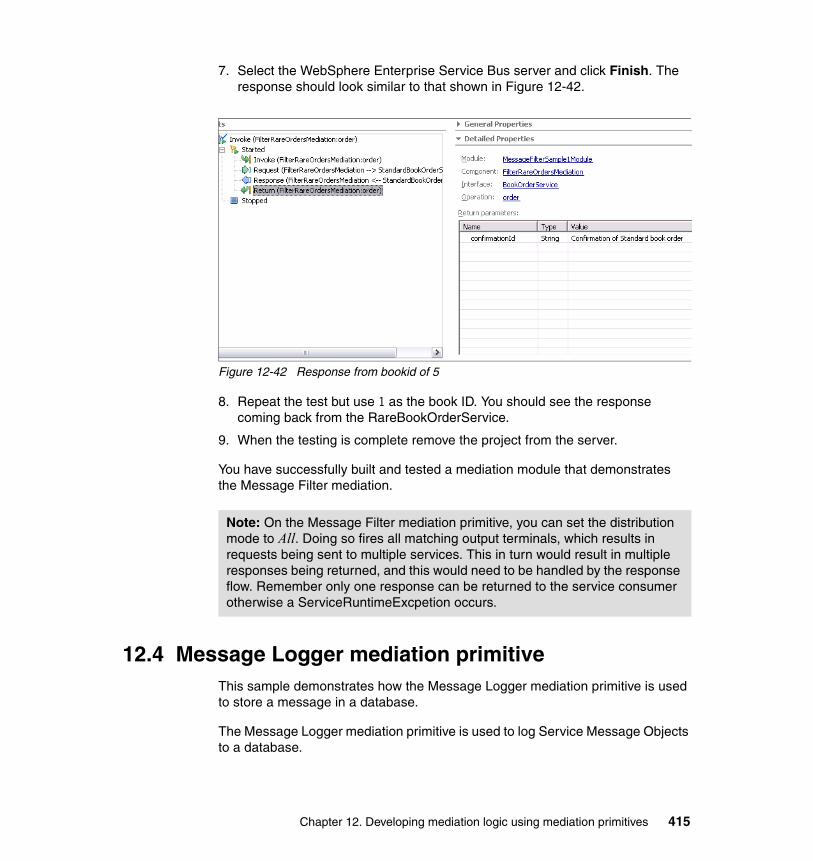
7. Select the WebSphere Enterprise Service Bus server and click Finish. The response should look similar to that shown in Figure 12-42.
Figure 12-42 Response from bookid of 5
8. Repeat the test but use 1 as the book ID. You should see the response coming back from the RareBookOrderService.
9. When the testing is complete remove the project from the server.
You have successfully built and tested a mediation module that demonstrates the Message Filter mediation.
12.4 Message Logger mediation primitiveThis sample demonstrates how the Message Logger mediation primitive is used to store a message in a database.
The Message Logger mediation primitive is used to log Service Message Objects to a database.
Note: On the Message Filter mediation primitive, you can set the distribution mode to All. Doing so fires all matching output terminals, which results in requests being sent to multiple services. This in turn would result in multiple responses being returned, and this would need to be handled by the response flow. Remember only one response can be returned to the service consumer otherwise a ServiceRuntimeExcpetion occurs.
Chapter 12. Developing mediation logic using mediation primitives 415
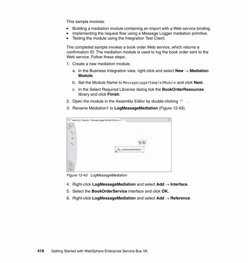
This sample involves:
� Building a mediation module containing an import with a Web service binding.� Implementing the request flow using a Message Logger mediation primitive.� Testing the module using the Integration Test Client.
The completed sample invokes a book order Web service, which returns a confirmation ID. The mediation module is used to log the book order sent to the Web service. Follow these steps:
1. Create a new mediation module.
a. In the Business Integration view, right-click and select New → Mediation Module.
b. Set the Module Name to MessageLoggerSample1Module and click Next.
c. In the Select Required Libraries dialog tick the BookOrderResources library and click Finish.
2. Open the module in the Assembly Editor by double-clicking .
3. Rename Mediation1 to LogMessageMediation (Figure 12-43).
Figure 12-43 LogMessageMediation
4. Right-click LogMessageMediation and select Add → Interface.
5. Select the BookOrderService interface and click OK.
6. Right-click LogMessageMediation and select Add → Reference.
416 Getting Started with WebSphere Enterprise Service Bus V6
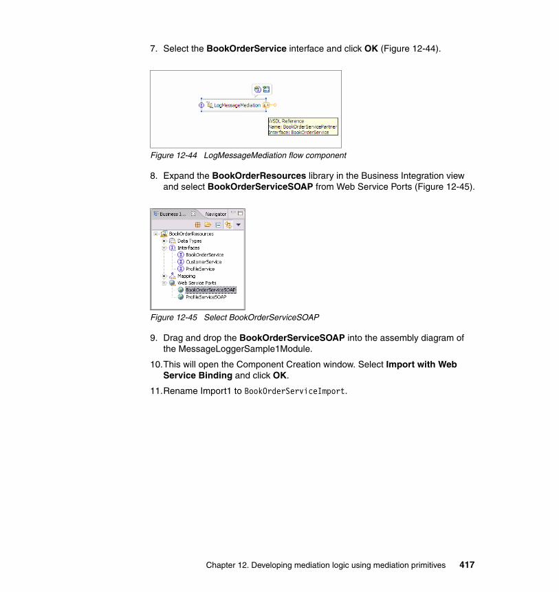
7. Select the BookOrderService interface and click OK (Figure 12-44).
Figure 12-44 LogMessageMediation flow component
8. Expand the BookOrderResources library in the Business Integration view and select BookOrderServiceSOAP from Web Service Ports (Figure 12-45).
Figure 12-45 Select BookOrderServiceSOAP
9. Drag and drop the BookOrderServiceSOAP into the assembly diagram of the MessageLoggerSample1Module.
10.This will open the Component Creation window. Select Import with Web Service Binding and click OK.
11.Rename Import1 to BookOrderServiceImport.
Chapter 12. Developing mediation logic using mediation primitives 417
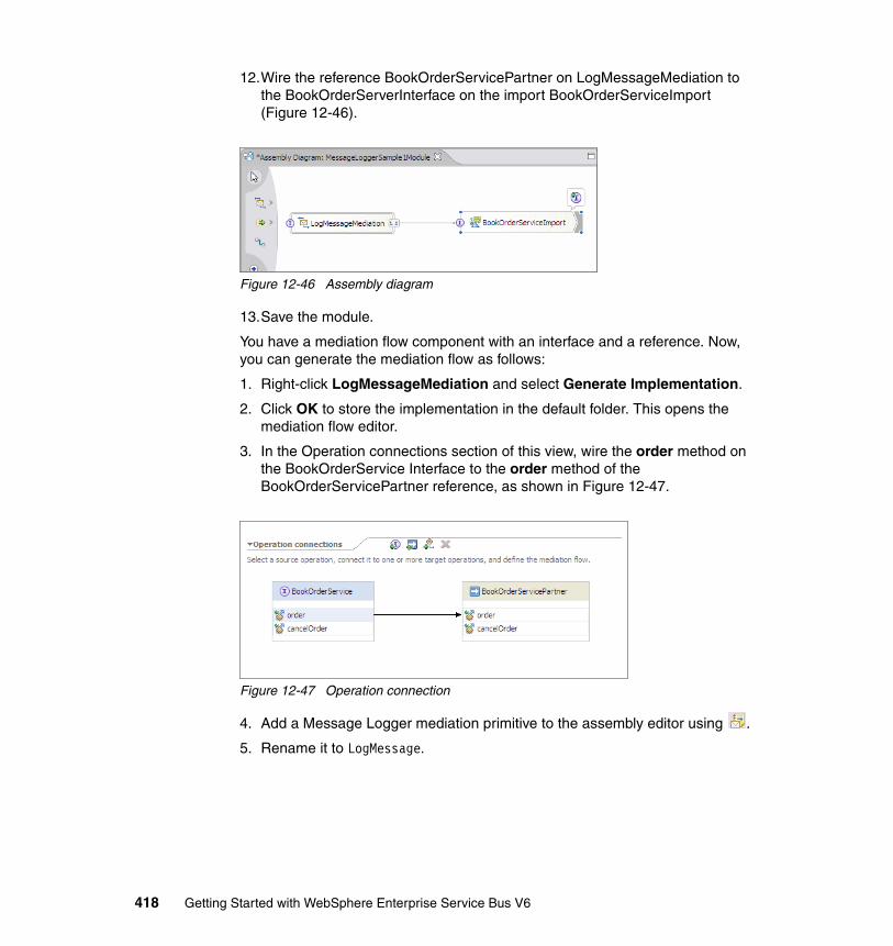
12.Wire the reference BookOrderServicePartner on LogMessageMediation to the BookOrderServerInterface on the import BookOrderServiceImport (Figure 12-46).
Figure 12-46 Assembly diagram
13.Save the module.
You have a mediation flow component with an interface and a reference. Now, you can generate the mediation flow as follows:
1. Right-click LogMessageMediation and select Generate Implementation.
2. Click OK to store the implementation in the default folder. This opens the mediation flow editor.
3. In the Operation connections section of this view, wire the order method on the BookOrderService Interface to the order method of the BookOrderServicePartner reference, as shown in Figure 12-47.
Figure 12-47 Operation connection
4. Add a Message Logger mediation primitive to the assembly editor using .
5. Rename it to LogMessage.
418 Getting Started with WebSphere Enterprise Service Bus V6
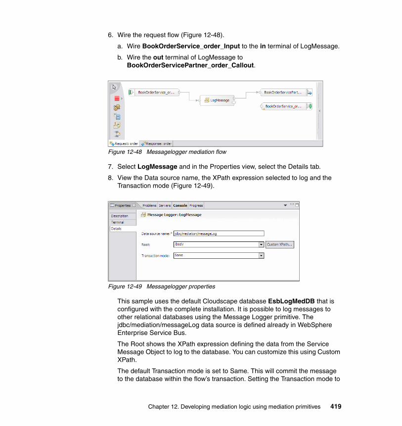
6. Wire the request flow (Figure 12-48).
a. Wire BookOrderService_order_Input to the in terminal of LogMessage.
b. Wire the out terminal of LogMessage to BookOrderServicePartner_order_Callout.
Figure 12-48 Messagelogger mediation flow
7. Select LogMessage and in the Properties view, select the Details tab.
8. View the Data source name, the XPath expression selected to log and the Transaction mode (Figure 12-49).
Figure 12-49 Messagelogger properties
This sample uses the default Cloudscape database EsbLogMedDB that is configured with the complete installation. It is possible to log messages to other relational databases using the Message Logger primitive. The jdbc/mediation/messageLog data source is defined already in WebSphere Enterprise Service Bus.
The Root shows the XPath expression defining the data from the Service Message Object to log to the database. You can customize this using Custom XPath.
The default Transaction mode is set to Same. This will commit the message to the database within the flow’s transaction. Setting the Transaction mode to
Chapter 12. Developing mediation logic using mediation primitives 419
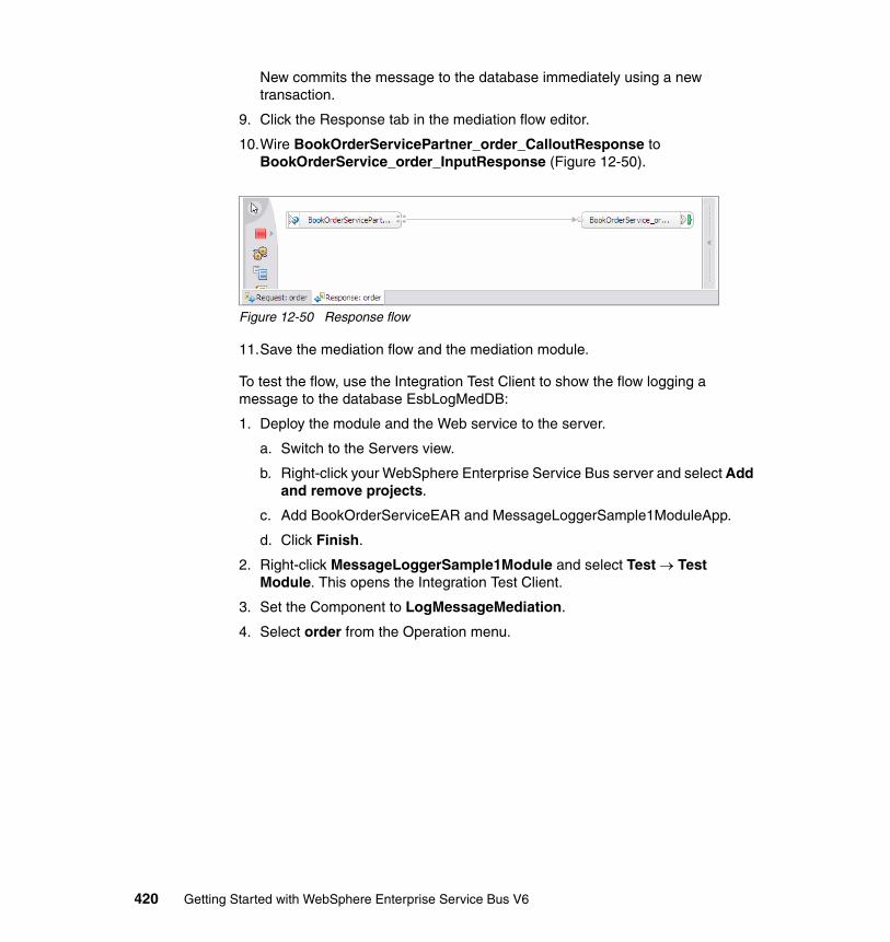
New commits the message to the database immediately using a new transaction.
9. Click the Response tab in the mediation flow editor.
10.Wire BookOrderServicePartner_order_CalloutResponse to BookOrderService_order_InputResponse (Figure 12-50).
Figure 12-50 Response flow
11.Save the mediation flow and the mediation module.
To test the flow, use the Integration Test Client to show the flow logging a message to the database EsbLogMedDB:
1. Deploy the module and the Web service to the server.
a. Switch to the Servers view.
b. Right-click your WebSphere Enterprise Service Bus server and select Add and remove projects.
c. Add BookOrderServiceEAR and MessageLoggerSample1ModuleApp.
d. Click Finish.
2. Right-click MessageLoggerSample1Module and select Test → Test Module. This opens the Integration Test Client.
3. Set the Component to LogMessageMediation.
4. Select order from the Operation menu.
420 Getting Started with WebSphere Enterprise Service Bus V6
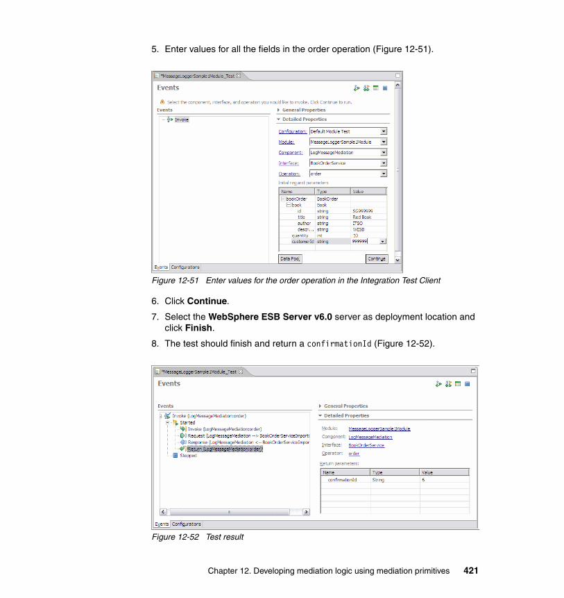
5. Enter values for all the fields in the order operation (Figure 12-51).
Figure 12-51 Enter values for the order operation in the Integration Test Client
6. Click Continue.
7. Select the WebSphere ESB Server v6.0 server as deployment location and click Finish.
8. The test should finish and return a confirmationId (Figure 12-52).
Figure 12-52 Test result
Chapter 12. Developing mediation logic using mediation primitives 421
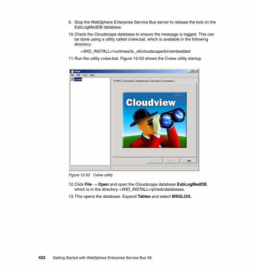
9. Stop the WebSphere Enterprise Service Bus server to release the lock on the EsbLogMedDB database.
10.Check the Cloudscape database to ensure the message is logged. This can be done using a utility called cview.bat, which is available in the following directory:
<WID_INSTALL>/runtimes/bi_v6/cloudscape/bin/embedded
11.Run the utility cview.bat. Figure 12-53 shows the Cview utility startup.
Figure 12-53 Cview utility
12.Click File → Open and open the Cloudscape database EsbLogMedDB, which is in the directory <WID_INSTALL>/pf/esb/databases.
13.This opens the database. Expand Tables and select MSGLOG.
422 Getting Started with WebSphere Enterprise Service Bus V6
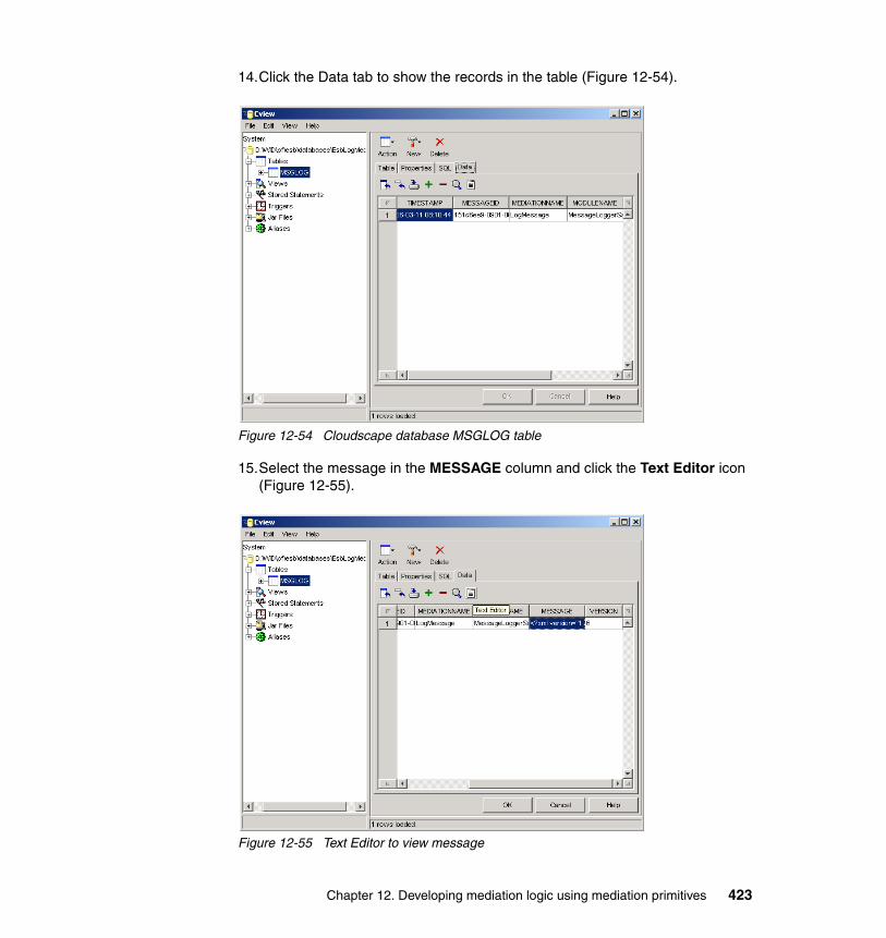
14.Click the Data tab to show the records in the table (Figure 12-54).
Figure 12-54 Cloudscape database MSGLOG table
15.Select the message in the MESSAGE column and click the Text Editor icon (Figure 12-55).
Figure 12-55 Text Editor to view message
Chapter 12. Developing mediation logic using mediation primitives 423
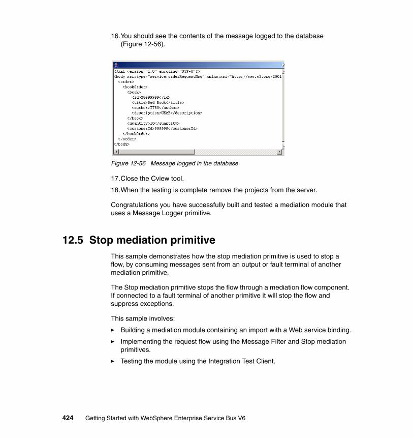
16.You should see the contents of the message logged to the database (Figure 12-56).
Figure 12-56 Message logged in the database
17.Close the Cview tool.
18.When the testing is complete remove the projects from the server.
Congratulations you have successfully built and tested a mediation module that uses a Message Logger primitive.
12.5 Stop mediation primitiveThis sample demonstrates how the stop mediation primitive is used to stop a flow, by consuming messages sent from an output or fault terminal of another mediation primitive.
The Stop mediation primitive stops the flow through a mediation flow component. If connected to a fault terminal of another primitive it will stop the flow and suppress exceptions.
This sample involves:
� Building a mediation module containing an import with a Web service binding.
� Implementing the request flow using the Message Filter and Stop mediation primitives.
� Testing the module using the Integration Test Client.
424 Getting Started with WebSphere Enterprise Service Bus V6
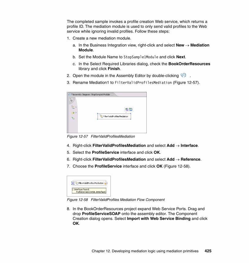
The completed sample invokes a profile creation Web service, which returns a profile ID. The mediation module is used to only send valid profiles to the Web service while ignoring invalid profiles. Follow these steps:
1. Create a new mediation module.
a. In the Business Integration view, right-click and select New → Mediation Module.
b. Set the Module Name to StopSample1Module and click Next.
c. In the Select Required Libraries dialog, check the BookOrderResources library and click Finish.
2. Open the module in the Assembly Editor by double-clicking .
3. Rename Mediation1 to FilterValidProfilesMediation (Figure 12-57).
Figure 12-57 FilterValidProfilesMediation
4. Right-click FilterValidProfilesMediation and select Add → Interface.
5. Select the ProfileService interface and click OK.
6. Right-click FilterValidProfilesMediation and select Add → Reference.
7. Choose the ProfileService interface and click OK (Figure 12-58).
Figure 12-58 FilterValidProfiles Mediation Flow Component
8. In the BookOrderResources project expand Web Service Ports. Drag and drop ProfileServiceSOAP onto the assembly editor. The Component Creation dialog opens. Select Import with Web Service Binding and click OK.
Chapter 12. Developing mediation logic using mediation primitives 425
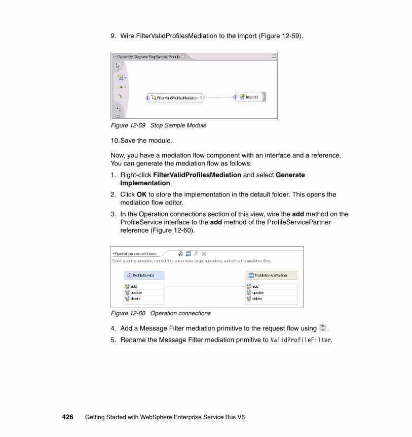
9. Wire FilterValidProfilesMediation to the import (Figure 12-59).
Figure 12-59 Stop Sample Module
10.Save the module.
Now, you have a mediation flow component with an interface and a reference. You can generate the mediation flow as follows:
1. Right-click FilterValidProfilesMediation and select Generate Implementation.
2. Click OK to store the implementation in the default folder. This opens the mediation flow editor.
3. In the Operation connections section of this view, wire the add method on the ProfileService interface to the add method of the ProfileServicePartner reference (Figure 12-60).
Figure 12-60 Operation connections
4. Add a Message Filter mediation primitive to the request flow using .
5. Rename the Message Filter mediation primitive to ValidProfileFilter.
426 Getting Started with WebSphere Enterprise Service Bus V6
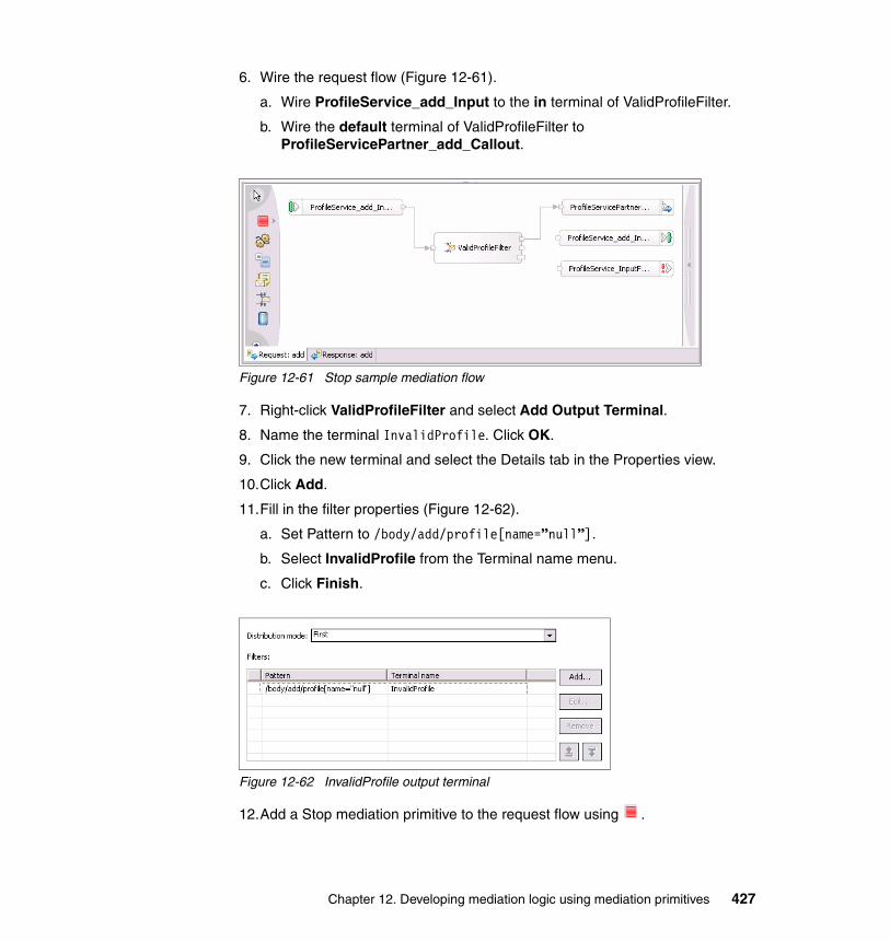
6. Wire the request flow (Figure 12-61).
a. Wire ProfileService_add_Input to the in terminal of ValidProfileFilter.
b. Wire the default terminal of ValidProfileFilter to ProfileServicePartner_add_Callout.
Figure 12-61 Stop sample mediation flow
7. Right-click ValidProfileFilter and select Add Output Terminal.
8. Name the terminal InvalidProfile. Click OK.
9. Click the new terminal and select the Details tab in the Properties view.
10.Click Add.
11.Fill in the filter properties (Figure 12-62).
a. Set Pattern to /body/add/profile[name=”null”].
b. Select InvalidProfile from the Terminal name menu.
c. Click Finish.
Figure 12-62 InvalidProfile output terminal
12.Add a Stop mediation primitive to the request flow using .
Chapter 12. Developing mediation logic using mediation primitives 427
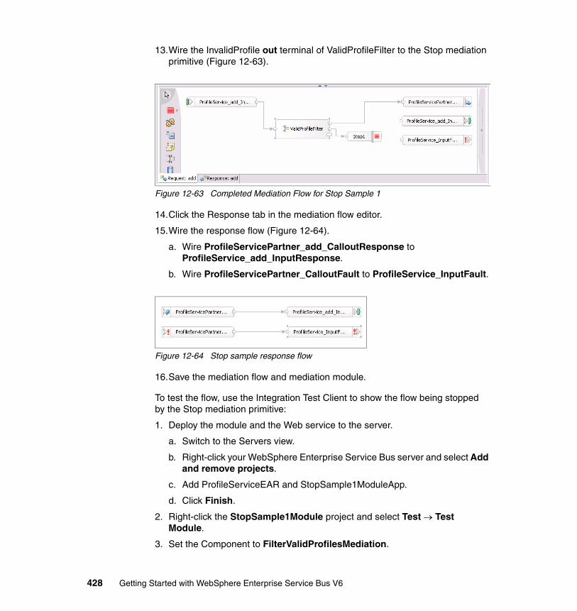
13.Wire the InvalidProfile out terminal of ValidProfileFilter to the Stop mediation primitive (Figure 12-63).
Figure 12-63 Completed Mediation Flow for Stop Sample 1
14.Click the Response tab in the mediation flow editor.
15.Wire the response flow (Figure 12-64).
a. Wire ProfileServicePartner_add_CalloutResponse to ProfileService_add_InputResponse.
b. Wire ProfileServicePartner_CalloutFault to ProfileService_InputFault.
Figure 12-64 Stop sample response flow
16.Save the mediation flow and mediation module.
To test the flow, use the Integration Test Client to show the flow being stopped by the Stop mediation primitive:
1. Deploy the module and the Web service to the server.
a. Switch to the Servers view.
b. Right-click your WebSphere Enterprise Service Bus server and select Add and remove projects.
c. Add ProfileServiceEAR and StopSample1ModuleApp.
d. Click Finish.
2. Right-click the StopSample1Module project and select Test → Test Module.
3. Set the Component to FilterValidProfilesMediation.
428 Getting Started with WebSphere Enterprise Service Bus V6
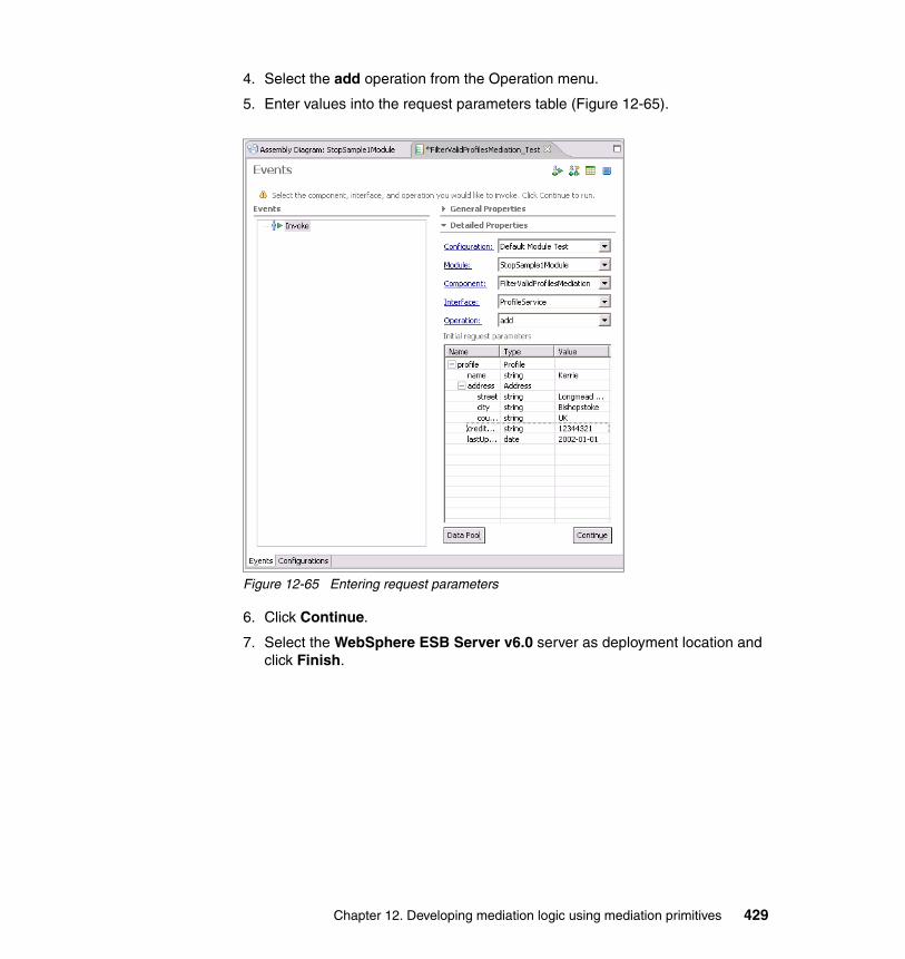
4. Select the add operation from the Operation menu.
5. Enter values into the request parameters table (Figure 12-65).
Figure 12-65 Entering request parameters
6. Click Continue.
7. Select the WebSphere ESB Server v6.0 server as deployment location and click Finish.
Chapter 12. Developing mediation logic using mediation primitives 429
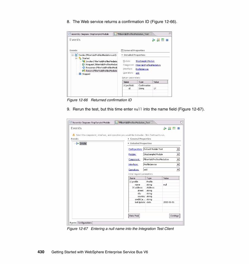
8. The Web service returns a confirmation ID (Figure 12-66).
Figure 12-66 Returned confirmation ID
9. Rerun the test, but this time enter null into the name field (Figure 12-67).
Figure 12-67 Entering a null name into the Integration Test Client
430 Getting Started with WebSphere Enterprise Service Bus V6

10.Click Continue.
11.You see the mediation flow is stopped and the profileId is null (Figure 12-68). The ProfileService Web service was not invoked.
Figure 12-68 Null profileId
12.When the testing is complete remove the projects from the server.
You have successfully built and tested a mediation module that uses a Stop mediation primitive.
Note: In this sample, if the default terminal of ValidProfileFilter is not connected to a Stop mediation primitive the flow would behave in the same way. However, using the Stop mediation primitive clarifies the intention of the flow. It also removes the output terminal not connected warnings from WebSphere Integration Developer.
Chapter 12. Developing mediation logic using mediation primitives 431
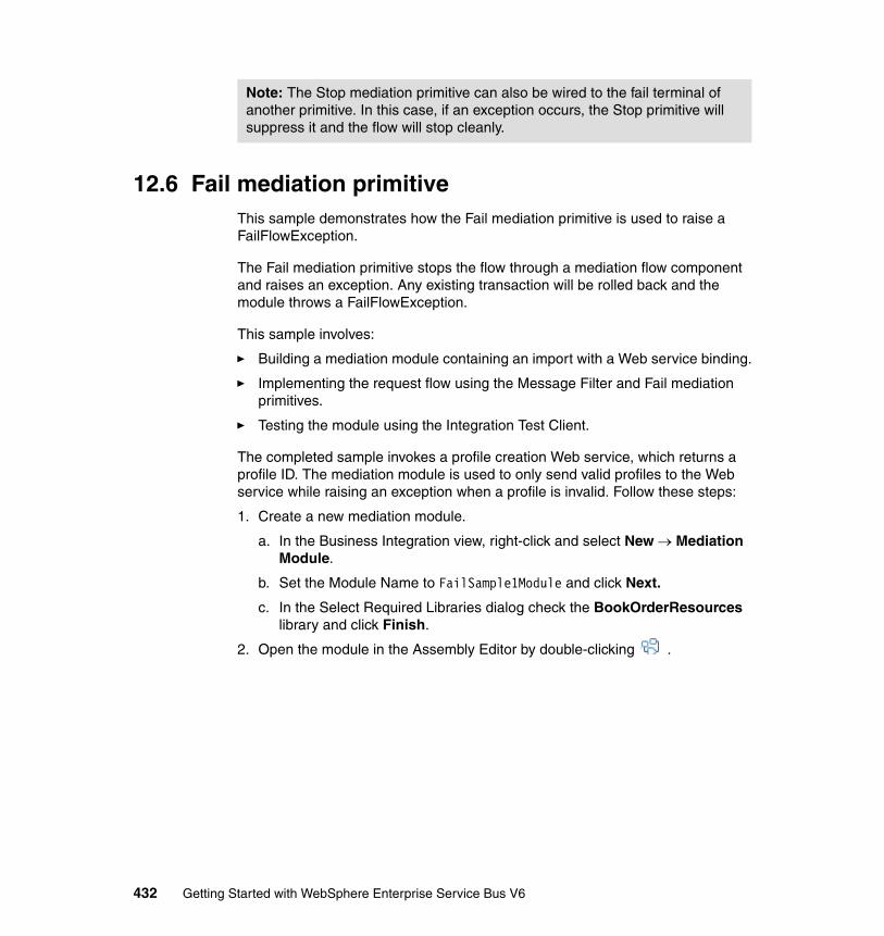
12.6 Fail mediation primitiveThis sample demonstrates how the Fail mediation primitive is used to raise a FailFlowException.
The Fail mediation primitive stops the flow through a mediation flow component and raises an exception. Any existing transaction will be rolled back and the module throws a FailFlowException.
This sample involves:
� Building a mediation module containing an import with a Web service binding.
� Implementing the request flow using the Message Filter and Fail mediation primitives.
� Testing the module using the Integration Test Client.
The completed sample invokes a profile creation Web service, which returns a profile ID. The mediation module is used to only send valid profiles to the Web service while raising an exception when a profile is invalid. Follow these steps:
1. Create a new mediation module.
a. In the Business Integration view, right-click and select New → Mediation Module.
b. Set the Module Name to FailSample1Module and click Next.
c. In the Select Required Libraries dialog check the BookOrderResources library and click Finish.
2. Open the module in the Assembly Editor by double-clicking .
Note: The Stop mediation primitive can also be wired to the fail terminal of another primitive. In this case, if an exception occurs, the Stop primitive will suppress it and the flow will stop cleanly.
432 Getting Started with WebSphere Enterprise Service Bus V6
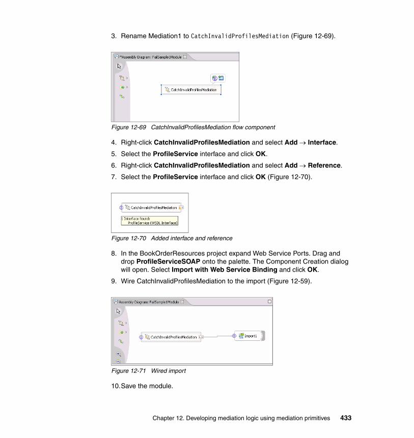
3. Rename Mediation1 to CatchInvalidProfilesMediation (Figure 12-69).
Figure 12-69 CatchInvalidProfilesMediation flow component
4. Right-click CatchInvalidProfilesMediation and select Add → Interface.
5. Select the ProfileService interface and click OK.
6. Right-click CatchInvalidProfilesMediation and select Add → Reference.
7. Select the ProfileService interface and click OK (Figure 12-70).
Figure 12-70 Added interface and reference
8. In the BookOrderResources project expand Web Service Ports. Drag and drop ProfileServiceSOAP onto the palette. The Component Creation dialog will open. Select Import with Web Service Binding and click OK.
9. Wire CatchInvalidProfilesMediation to the import (Figure 12-59).
Figure 12-71 Wired import
10.Save the module.
Chapter 12. Developing mediation logic using mediation primitives 433
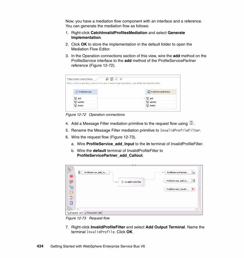
Now, you have a mediation flow component with an interface and a reference. You can generate the mediation flow as follows:
1. Right-click CatchInvalidProfilesMediation and select Generate Implementation.
2. Click OK to store the implementation in the default folder to open the Mediation Flow Editor.
3. In the Operation connections section of this view, wire the add method on the ProfileService interface to the add method of the ProfileServicePartner reference (Figure 12-72).
Figure 12-72 Operation connections
4. Add a Message Filter mediation primitive to the request flow using .
5. Rename the Message Filter mediation primitive to InvalidProfileFilter.
6. Wire the request flow (Figure 12-73).
a. Wire ProfileService_add_Input to the in terminal of InvalidProfileFilter.
b. Wire the default terminal of InvalidProfileFilter to ProfileServicePartner_add_Callout.
Figure 12-73 Request flow
7. Right-click InvalidProfileFilter and select Add Output Terminal. Name the terminal InvalidProfile. Click OK.
434 Getting Started with WebSphere Enterprise Service Bus V6
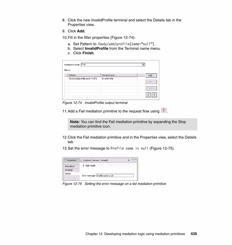
8. Click the new InvalidProfile terminal and select the Details tab in the Properties view.
9. Click Add.
10.Fill in the filter properties (Figure 12-74):
a. Set Pattern to /body/add/profile[name=”null”].b. Select InvalidProfile from the Terminal name menu.c. Click Finish.
Figure 12-74 InvalidProfile output terminal
11.Add a Fail mediation primitive to the request flow using .
12.Click the Fail mediation primitive and in the Properties view, select the Details tab.
13.Set the error message to Profile name is null (Figure 12-75).
Figure 12-75 Setting the error message on a fail mediation primitive
Note: You can find the Fail mediation primitive by expanding the Stop mediation primitive icon.
Chapter 12. Developing mediation logic using mediation primitives 435
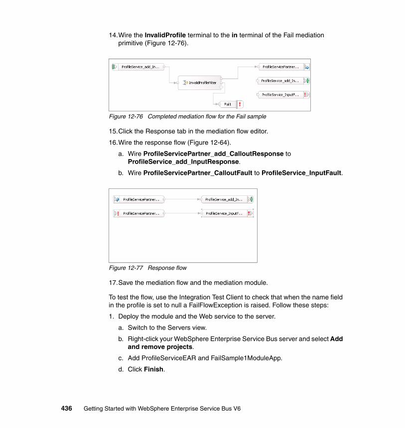
14.Wire the InvalidProfile terminal to the in terminal of the Fail mediation primitive (Figure 12-76).
Figure 12-76 Completed mediation flow for the Fail sample
15.Click the Response tab in the mediation flow editor.
16.Wire the response flow (Figure 12-64).
a. Wire ProfileServicePartner_add_CalloutResponse to ProfileService_add_InputResponse.
b. Wire ProfileServicePartner_CalloutFault to ProfileService_InputFault.
Figure 12-77 Response flow
17.Save the mediation flow and the mediation module.
To test the flow, use the Integration Test Client to check that when the name field in the profile is set to null a FailFlowException is raised. Follow these steps:
1. Deploy the module and the Web service to the server.
a. Switch to the Servers view.
b. Right-click your WebSphere Enterprise Service Bus server and select Add and remove projects.
c. Add ProfileServiceEAR and FailSample1ModuleApp.
d. Click Finish.
436 Getting Started with WebSphere Enterprise Service Bus V6
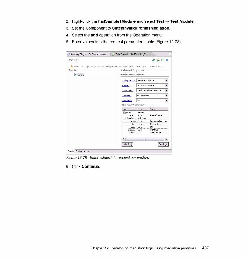
2. Right-click the FailSample1Module and select Test → Test Module.
3. Set the Component to CatchInvalidProfilesMediation.
4. Select the add operation from the Operation menu.
5. Enter values into the request parameters table (Figure 12-78).
Figure 12-78 Enter values into request parameters
6. Click Continue.
Chapter 12. Developing mediation logic using mediation primitives 437
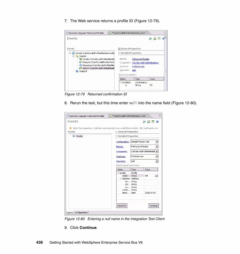
7. The Web service returns a profile ID (Figure 12-79).
Figure 12-79 Returned confirmation ID
8. Rerun the test, but this time enter null into the name field (Figure 12-80).
Figure 12-80 Entering a null name in the Integration Test Client
9. Click Continue.
438 Getting Started with WebSphere Enterprise Service Bus V6

10.A FailFlowException is raised that contains the message that we defined (Figure 12-81).
Figure 12-81 Testing the Fail mediation primitive
11.When the testing is complete, remove the projects from the server.
You have successfully created and tested a module containing a Fail mediation primitive.
12.7 Custom mediation primitiveThis sample demonstrates Custom mediation primitives. It also introduces the use of the mediation flow’s correlation context.
The Custom mediation primitive allows the user to implement their own mediate method using Java. The Custom mediation, like the other primitives, receives a Service Message Object and returns a Service Message Object. It can be used to perform tasks that cannot be performed by using the other mediation primitives.
Note: If a transaction is in progress, when the mediation flow is stopped by a fail mediation primitive, the transaction is rolled back, and the FailFlowException is stored in the transient context.
Chapter 12. Developing mediation logic using mediation primitives 439
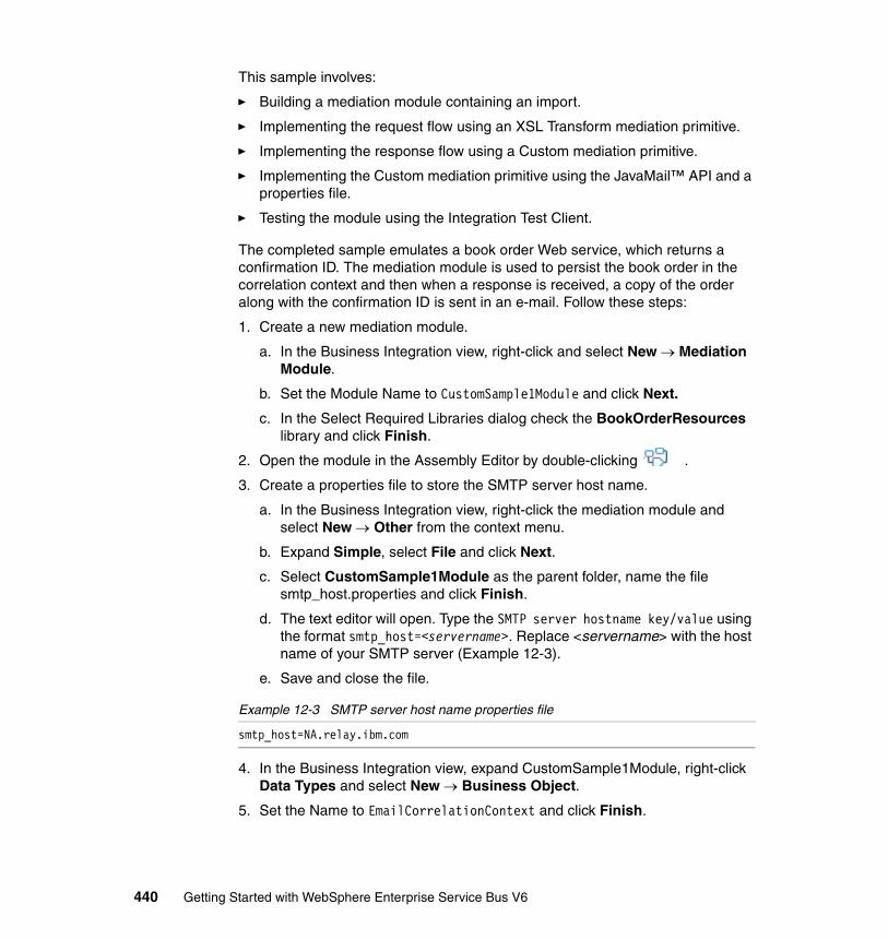
This sample involves:
� Building a mediation module containing an import.
� Implementing the request flow using an XSL Transform mediation primitive.
� Implementing the response flow using a Custom mediation primitive.
� Implementing the Custom mediation primitive using the JavaMail™ API and a properties file.
� Testing the module using the Integration Test Client.
The completed sample emulates a book order Web service, which returns a confirmation ID. The mediation module is used to persist the book order in the correlation context and then when a response is received, a copy of the order along with the confirmation ID is sent in an e-mail. Follow these steps:
1. Create a new mediation module.
a. In the Business Integration view, right-click and select New → Mediation Module.
b. Set the Module Name to CustomSample1Module and click Next.
c. In the Select Required Libraries dialog check the BookOrderResources library and click Finish.
2. Open the module in the Assembly Editor by double-clicking .
3. Create a properties file to store the SMTP server host name.
a. In the Business Integration view, right-click the mediation module and select New → Other from the context menu.
b. Expand Simple, select File and click Next.
c. Select CustomSample1Module as the parent folder, name the file smtp_host.properties and click Finish.
d. The text editor will open. Type the SMTP server hostname key/value using the format smtp_host=<servername>. Replace <servername> with the host name of your SMTP server (Example 12-3).
e. Save and close the file.
Example 12-3 SMTP server host name properties file
smtp_host=NA.relay.ibm.com
4. In the Business Integration view, expand CustomSample1Module, right-click Data Types and select New → Business Object.
5. Set the Name to EmailCorrelationContext and click Finish.
440 Getting Started with WebSphere Enterprise Service Bus V6
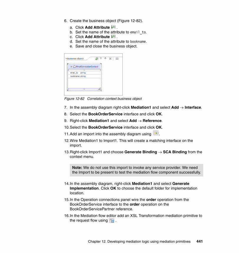
6. Create the business object (Figure 12-82).
a. Click Add Attribute .b. Set the name of the attribute to email_to.c. Click Add Attribute .d. Set the name of the attribute to bookname.e. Save and close the business object.
Figure 12-82 Correlation context business object
7. In the assembly diagram right-click Mediation1 and select Add → Interface.
8. Select the BookOrderService interface and click OK.
9. Right-click Mediation1 and select Add → Reference.
10.Select the BookOrderService interface and click OK.
11.Add an import into the assembly diagram using .
12.Wire Mediation1 to Import1. This will create a matching interface on the import.
13.Right-click Import1 and choose Generate Binding → SCA Binding from the context menu.
14.In the assembly diagram, right-click Mediation1 and select Generate Implementation. Click OK to choose the default folder for implementation location.
15.In the Operation connections panel wire the order operation from the BookOrderService interface to the order operation on the BookOrderServicePartner reference.
16.In the Mediation flow editor add an XSL Transformation mediation primitive to the request flow using .
Note: We do not use this import to invoke any service provider. We need the Import to be present to test the mediation flow component successfully.
Chapter 12. Developing mediation logic using mediation primitives 441
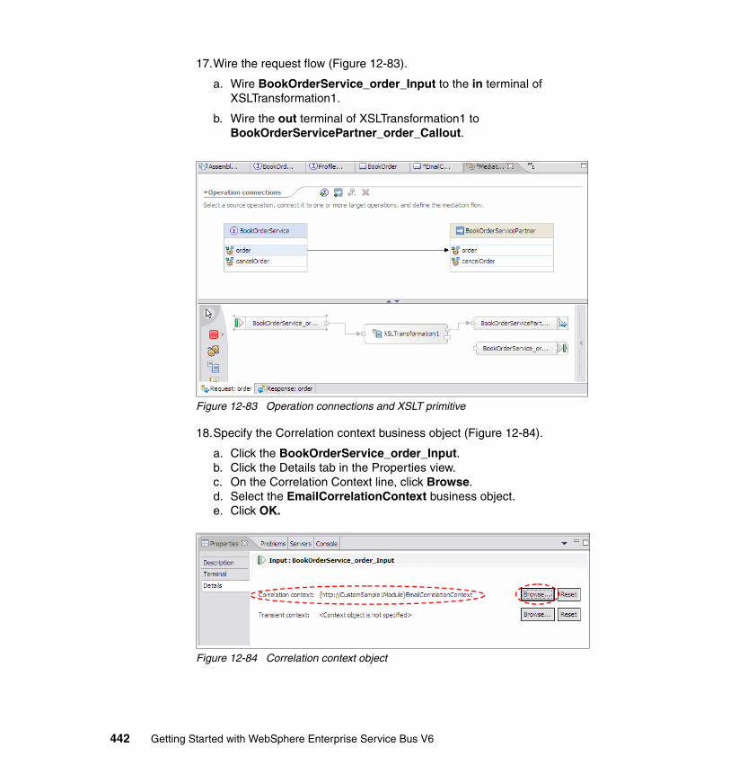
17.Wire the request flow (Figure 12-83).
a. Wire BookOrderService_order_Input to the in terminal of XSLTransformation1.
b. Wire the out terminal of XSLTransformation1 to BookOrderServicePartner_order_Callout.
Figure 12-83 Operation connections and XSLT primitive
18.Specify the Correlation context business object (Figure 12-84).
a. Click the BookOrderService_order_Input.b. Click the Details tab in the Properties view.c. On the Correlation Context line, click Browse.d. Select the EmailCorrelationContext business object.e. Click OK.
Figure 12-84 Correlation context object
442 Getting Started with WebSphere Enterprise Service Bus V6

19.Create a new XSL Transformation mapping.
a. Click the XSLTransformation1 primitive to select it.
b. Click the Details tab in the Properties view.
c. In the Root menu select the backslash (/).
d. Click New.
e. Leave the input and output messages unchanged (orderRequestMsg) and click Finish.
20.Define the XSL Mapping (Figure 12-85 on page 444).
a. Propagate the headers element by selecting the headers element on the source SMO, then selecting the headers element on the target SMO.
b. Right-click the headers element in the source panel and select Match Mapping from the context menu.
c. Propagate the body element by selecting the body element on the source SMO, then selecting the body element on the target SMO.
d. Right-click the body element in the source panel and select Match Mapping from the context menu.
e. Store the required values in the correlation context.
i. Drag body → order → bookOrder → book → title in the source SMO to context → correlation → bookname in the target SMO.
ii. Drag body → order → bookOrder → customerId in the source SMO to context → correlation → email_to in the target SMO.
Note: In this sample, we use the customer’s e-mail address as the customer ID.
Chapter 12. Developing mediation logic using mediation primitives 443
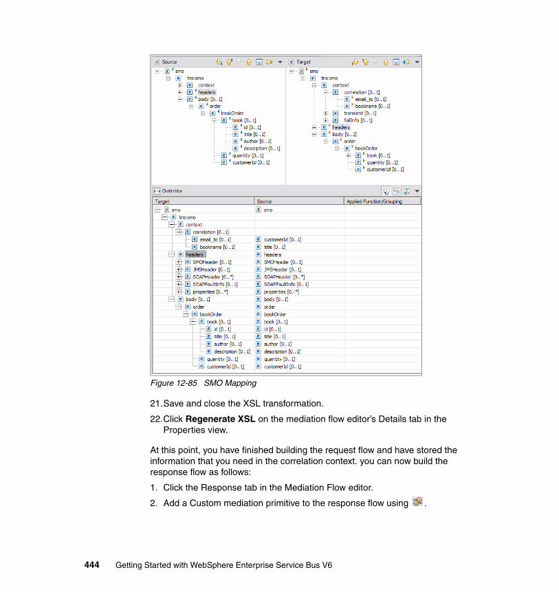
Figure 12-85 SMO Mapping
21.Save and close the XSL transformation.
22.Click Regenerate XSL on the mediation flow editor’s Details tab in the Properties view.
At this point, you have finished building the request flow and have stored the information that you need in the correlation context. you can now build the response flow as follows:
1. Click the Response tab in the Mediation Flow editor.
2. Add a Custom mediation primitive to the response flow using .
444 Getting Started with WebSphere Enterprise Service Bus V6
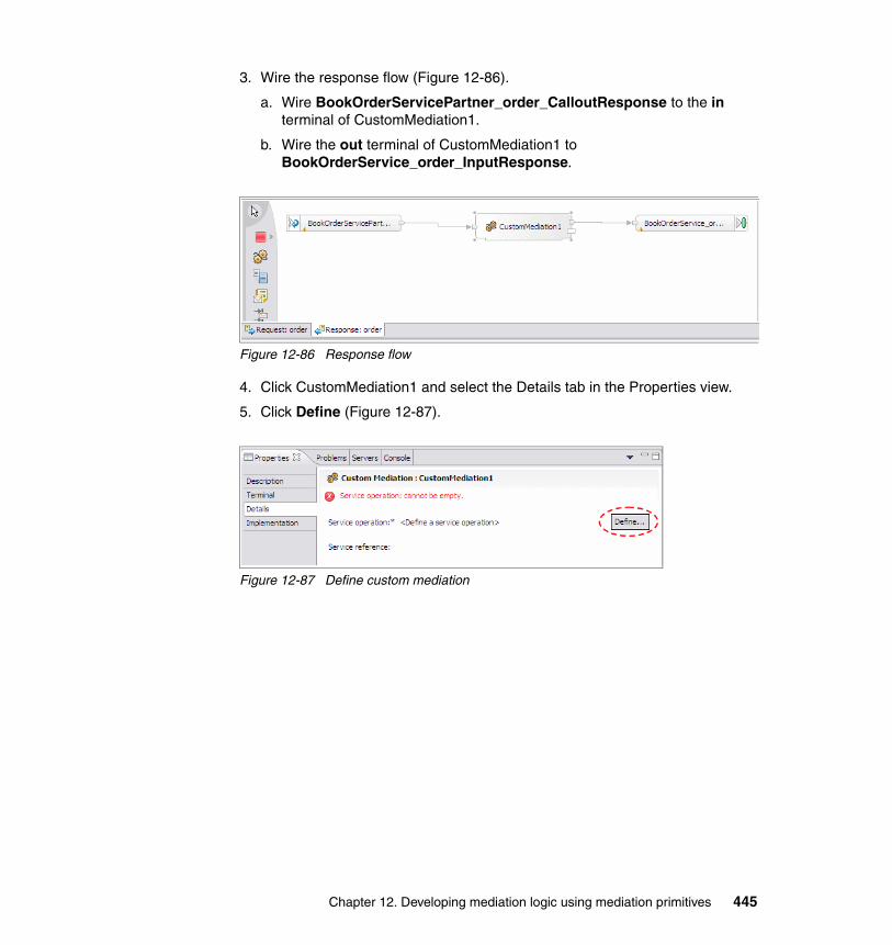
3. Wire the response flow (Figure 12-86).
a. Wire BookOrderServicePartner_order_CalloutResponse to the in terminal of CustomMediation1.
b. Wire the out terminal of CustomMediation1 to BookOrderService_order_InputResponse.
Figure 12-86 Response flow
4. Click CustomMediation1 and select the Details tab in the Properties view.
5. Click Define (Figure 12-87).
Figure 12-87 Define custom mediation
Chapter 12. Developing mediation logic using mediation primitives 445
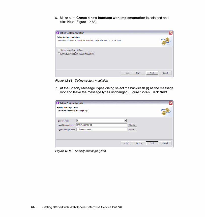
6. Make sure Create a new interface with implementation is selected and click Next (Figure 12-88).
Figure 12-88 Define custom mediation
7. At the Specify Message Types dialog select the backslash (/) as the message root and leave the message types unchanged (Figure 12-89). Click Next.
Figure 12-89 Specify message types
446 Getting Started with WebSphere Enterprise Service Bus V6
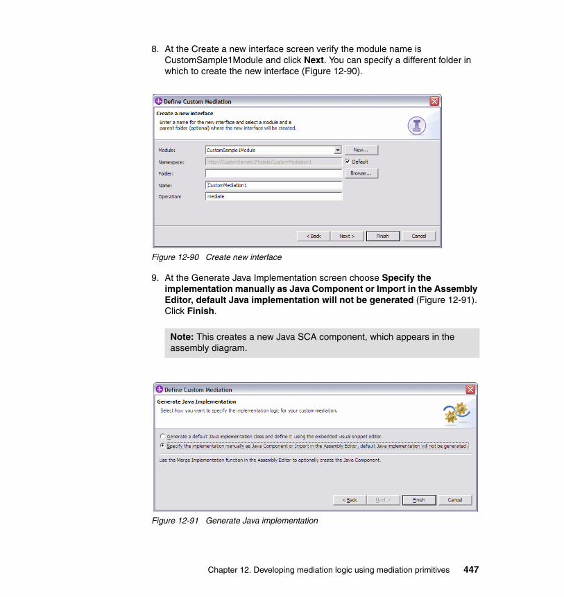
8. At the Create a new interface screen verify the module name is CustomSample1Module and click Next. You can specify a different folder in which to create the new interface (Figure 12-90).
Figure 12-90 Create new interface
9. At the Generate Java Implementation screen choose Specify the implementation manually as Java Component or Import in the Assembly Editor, default Java implementation will not be generated (Figure 12-91). Click Finish.
Figure 12-91 Generate Java implementation
Note: This creates a new Java SCA component, which appears in the assembly diagram.
Chapter 12. Developing mediation logic using mediation primitives 447
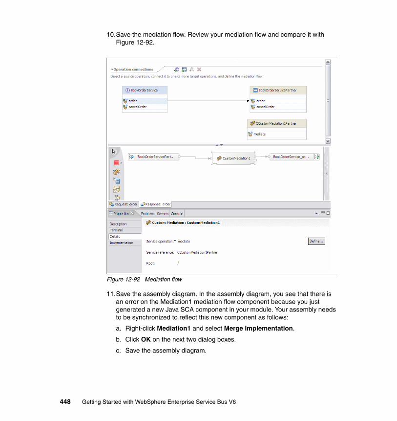
10.Save the mediation flow. Review your mediation flow and compare it with Figure 12-92.
Figure 12-92 Mediation flow
11.Save the assembly diagram. In the assembly diagram, you see that there is an error on the Mediation1 mediation flow component because you just generated a new Java SCA component in your module. Your assembly needs to be synchronized to reflect this new component as follows:
a. Right-click Mediation1 and select Merge Implementation.
b. Click OK on the next two dialog boxes.
c. Save the assembly diagram.
448 Getting Started with WebSphere Enterprise Service Bus V6
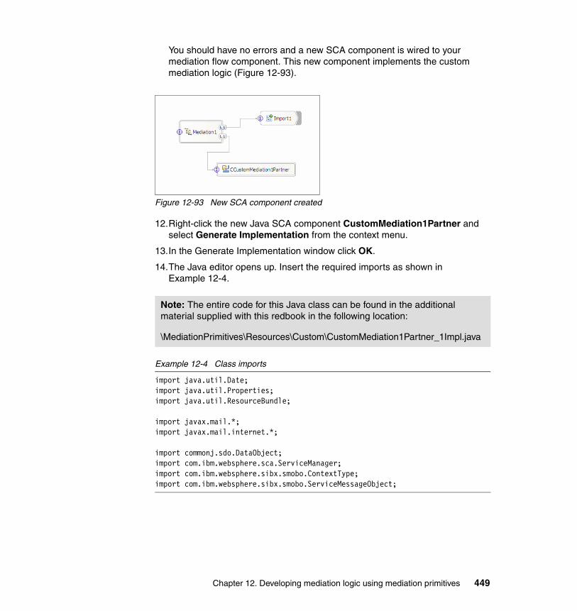
You should have no errors and a new SCA component is wired to your mediation flow component. This new component implements the custom mediation logic (Figure 12-93).
Figure 12-93 New SCA component created
12.Right-click the new Java SCA component CustomMediation1Partner and select Generate Implementation from the context menu.
13.In the Generate Implementation window click OK.
14.The Java editor opens up. Insert the required imports as shown in Example 12-4.
Example 12-4 Class imports
import java.util.Date;import java.util.Properties;import java.util.ResourceBundle;
import javax.mail.*;import javax.mail.internet.*;
import commonj.sdo.DataObject;import com.ibm.websphere.sca.ServiceManager;import com.ibm.websphere.sibx.smobo.ContextType;import com.ibm.websphere.sibx.smobo.ServiceMessageObject;
Note: The entire code for this Java class can be found in the additional material supplied with this redbook in the following location:
\MediationPrimitives\Resources\Custom\CustomMediation1Partner_1Impl.java
Chapter 12. Developing mediation logic using mediation primitives 449
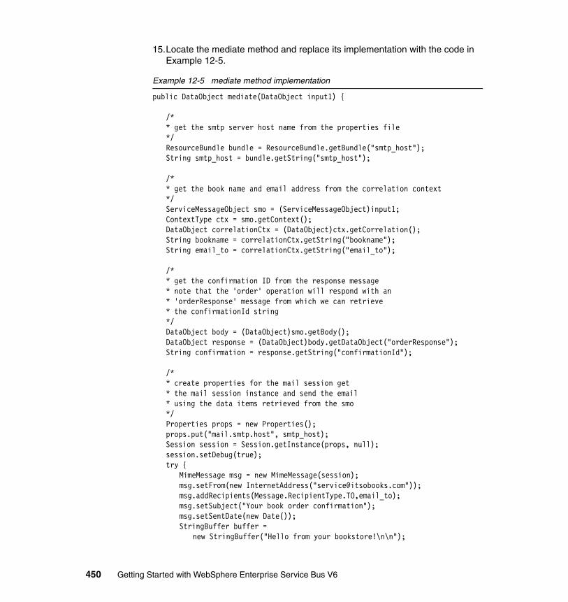
15.Locate the mediate method and replace its implementation with the code in Example 12-5.
Example 12-5 mediate method implementation
public DataObject mediate(DataObject input1) {
/** get the smtp server host name from the properties file*/ResourceBundle bundle = ResourceBundle.getBundle("smtp_host");String smtp_host = bundle.getString("smtp_host");
/** get the book name and email address from the correlation context*/ ServiceMessageObject smo = (ServiceMessageObject)input1;ContextType ctx = smo.getContext();DataObject correlationCtx = (DataObject)ctx.getCorrelation();String bookname = correlationCtx.getString("bookname");String email_to = correlationCtx.getString("email_to");
/** get the confirmation ID from the response message* note that the 'order' operation will respond with an* 'orderResponse' message from which we can retrieve* the confirmationId string*/DataObject body = (DataObject)smo.getBody();DataObject response = (DataObject)body.getDataObject("orderResponse");String confirmation = response.getString("confirmationId");
/** create properties for the mail session get * the mail session instance and send the email * using the data items retrieved from the smo*/Properties props = new Properties();props.put("mail.smtp.host", smtp_host);Session session = Session.getInstance(props, null);session.setDebug(true);try {
MimeMessage msg = new MimeMessage(session);msg.setFrom(new InternetAddress("[email protected]"));msg.addRecipients(Message.RecipientType.TO,email_to);msg.setSubject("Your book order confirmation");msg.setSentDate(new Date());StringBuffer buffer =
new StringBuffer("Hello from your bookstore!\n\n");
450 Getting Started with WebSphere Enterprise Service Bus V6
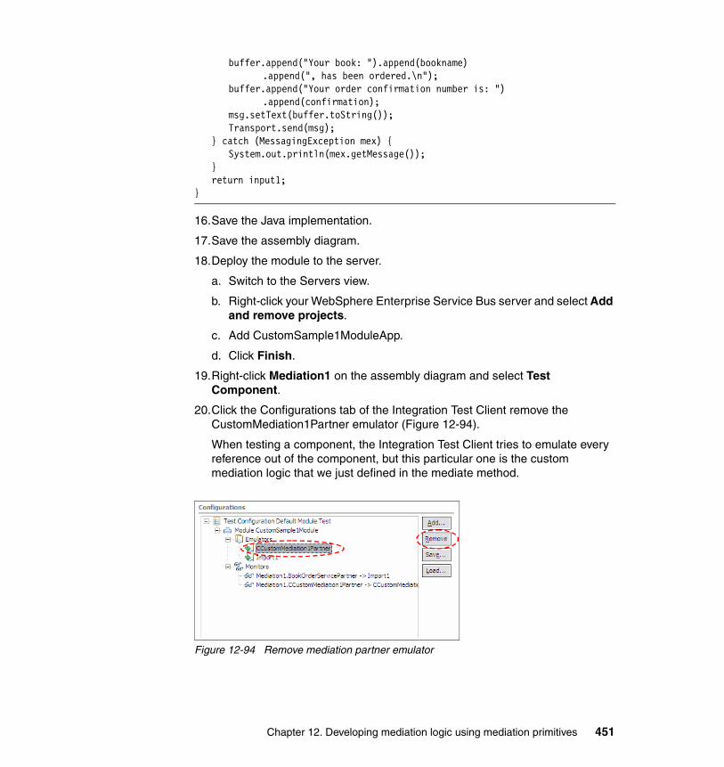
buffer.append("Your book: ").append(bookname).append(", has been ordered.\n");
buffer.append("Your order confirmation number is: ").append(confirmation);
msg.setText(buffer.toString());Transport.send(msg);
} catch (MessagingException mex) {System.out.println(mex.getMessage());
}return input1;
}
16.Save the Java implementation.
17.Save the assembly diagram.
18.Deploy the module to the server.
a. Switch to the Servers view.
b. Right-click your WebSphere Enterprise Service Bus server and select Add and remove projects.
c. Add CustomSample1ModuleApp.
d. Click Finish.
19.Right-click Mediation1 on the assembly diagram and select Test Component.
20.Click the Configurations tab of the Integration Test Client remove the CustomMediation1Partner emulator (Figure 12-94).
When testing a component, the Integration Test Client tries to emulate every reference out of the component, but this particular one is the custom mediation logic that we just defined in the mediate method.
Figure 12-94 Remove mediation partner emulator
Chapter 12. Developing mediation logic using mediation primitives 451
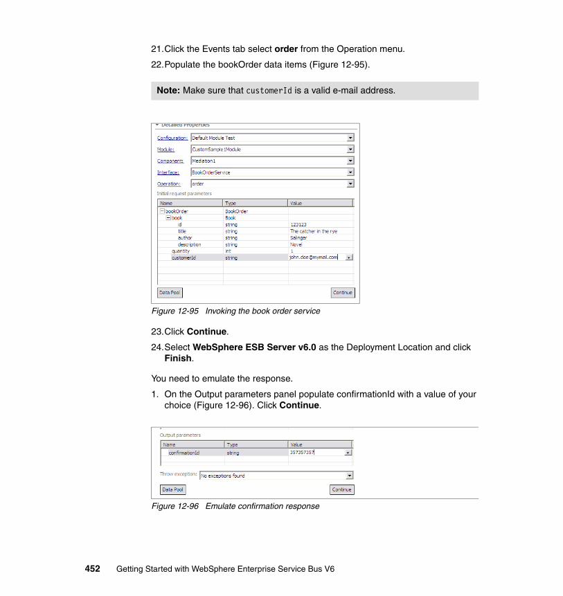
21.Click the Events tab select order from the Operation menu.
22.Populate the bookOrder data items (Figure 12-95).
Figure 12-95 Invoking the book order service
23.Click Continue.
24.Select WebSphere ESB Server v6.0 as the Deployment Location and click Finish.
You need to emulate the response.
1. On the Output parameters panel populate confirmationId with a value of your choice (Figure 12-96). Click Continue.
Figure 12-96 Emulate confirmation response
Note: Make sure that customerId is a valid e-mail address.
452 Getting Started with WebSphere Enterprise Service Bus V6
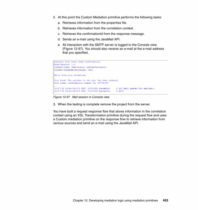
2. At this point the Custom Mediation primitive performs the following tasks:
a. Retrieves information from the properties file.
b. Retrieves information from the correlation context.
c. Retrieves the confirmationId from the response message.
d. Sends an e-mail using the JavaMail API.
e. All interaction with the SMTP server is logged to the Console view. (Figure 12-97). You should also receive an e-mail at the e-mail address that you specified.
Figure 12-97 Mail session in Console view
3. When the testing is complete remove the project from the server.
You have built a request response flow that stores information in the correlation context using an XSL Transformation primitive during the request flow and uses a Custom mediation primitive on the response flow to retrieve information from various sources and send an e-mail using the JavaMail API.
Chapter 12. Developing mediation logic using mediation primitives 453

454 Getting Started with WebSphere Enterprise Service Bus V6

Chapter 13. Configuring modules to provide quality of service
This chapter describes how to add quality of service functions to mediation modules. It describes three step-by-step examples
� 13.1, “CEI events” on page 456
Describes how to add CEI events to a mediation flow and how to browse CEI events.
� 13.2, “Security” on page 465
Describes how to apply security to mediation modules.
� 13.3, “Transactions” on page 474
Describes how to add transactional scopes to mediation modules.
These development examples assume you have configured your WebSphere Integration Developer workspace as described in Chapter 10, “Preparing for the development examples” on page 281.
You can import each of the development examples in this chapter as Project Interchange files (except for the transactions example) from the additional material that is supplied with this redbook in the \QualityOfService\Solutions directory.
13
© Copyright IBM Corp. 2006. All rights reserved. 455
13.1 CEI eventsCommon Event Infrastructure (CEI) provides basic event management services, such as event generation, transmission, persistence, and consumption.
This sample explores the CEI events by specifying event logging in a simple mediation flow, executing the flow and viewing the logged messages in the database.
This sample involves:
� Building a mediation module containing an export with a Web service bindings.
� Implementing the request flow using a Stop mediation primitive.
� Using the Event Monitor to enable CEI events.
� Testing the module using the Integration Test Client.
� Using the CBE Event Browser to view events
� Viewing events in a Cloudscape database.
The completed sample creates a CEI event when the foo method is called on the FooInterface. Follow these steps:
1. Create a new mediation module.
a. In the Business Integration view, right-click and select New → Mediation Module.
b. Set the Module Name to CEISample1Module and click Finish.
2. In the Business Integration view, in the CEISample1Module, right-click Interfaces and select New → Interface.
3. Name the interface FooInterface and click Finish.
456 Getting Started with WebSphere Enterprise Service Bus V6
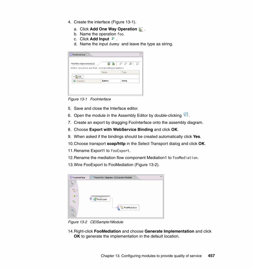
4. Create the interface (Figure 13-1).
a. Click Add One Way Operation .b. Name the operation foo.c. Click Add Input .d. Name the input dummy and leave the type as string.
Figure 13-1 FooInterface
5. Save and close the Interface editor.
6. Open the module in the Assembly Editor by double-clicking .
7. Create an export by dragging FooInterface onto the assembly diagram.
8. Choose Export with WebService Binding and click OK.
9. When asked if the bindings should be created automatically click Yes.
10.Choose transport soap/http in the Select Transport dialog and click OK.
11.Rename Export1 to FooExport.
12.Rename the mediation flow component Mediation1 to FooMediation.
13.Wire FooExport to FooMediation (Figure 13-2).
Figure 13-2 CEISample1Module
14.Right-click FooMediation and choose Generate Implementation and click OK to generate the implementation in the default location.
Chapter 13. Configuring modules to provide quality of service 457
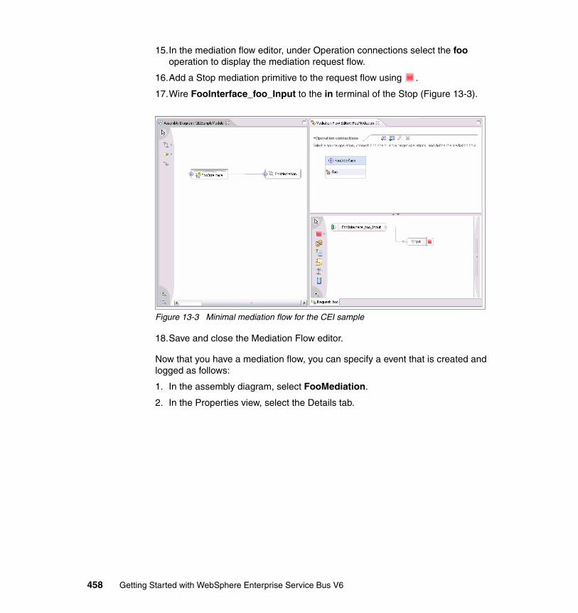
15.In the mediation flow editor, under Operation connections select the foo operation to display the mediation request flow.
16.Add a Stop mediation primitive to the request flow using .
17.Wire FooInterface_foo_Input to the in terminal of the Stop (Figure 13-3).
Figure 13-3 Minimal mediation flow for the CEI sample
18.Save and close the Mediation Flow editor.
Now that you have a mediation flow, you can specify a event that is created and logged as follows:
1. In the assembly diagram, select FooMediation.
2. In the Properties view, select the Details tab.
458 Getting Started with WebSphere Enterprise Service Bus V6

3. Expand FooInterface and select the foo operation (Figure 13-4).
Figure 13-4 Foo operation in properties view
In WebSphere Integration Developer you have to specify which operations (associated with elements of the assembly editor, such as imports, exports, mediation flow components and Java components) should create events. After you select an operation applicable for creating custom events, you have to change the setting from None to either All or to Selected to specify which of the predefined events should be generated at runtime.
Chapter 13. Configuring modules to provide quality of service 459
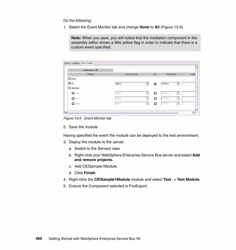
Do the following:
1. Select the Event Monitor tab and change None to All (Figure 13-5).
Figure 13-5 Event Monitor tab
2. Save the module.
Having specified the event the module can be deployed to the test environment.
3. Deploy the module to the server.
a. Switch to the Servers view.
b. Right-click your WebSphere Enterprise Service Bus server and select Add and remove projects.
c. Add CEISample1Module.
d. Click Finish.
4. Right-click the CEISample1Module module and select Test → Test Module.
5. Ensure the Component selected is FooExport.
Note: When you save, you will notice that the mediation component in the assembly editor shows a little yellow flag in order to indicate that there is a custom event specified.
460 Getting Started with WebSphere Enterprise Service Bus V6
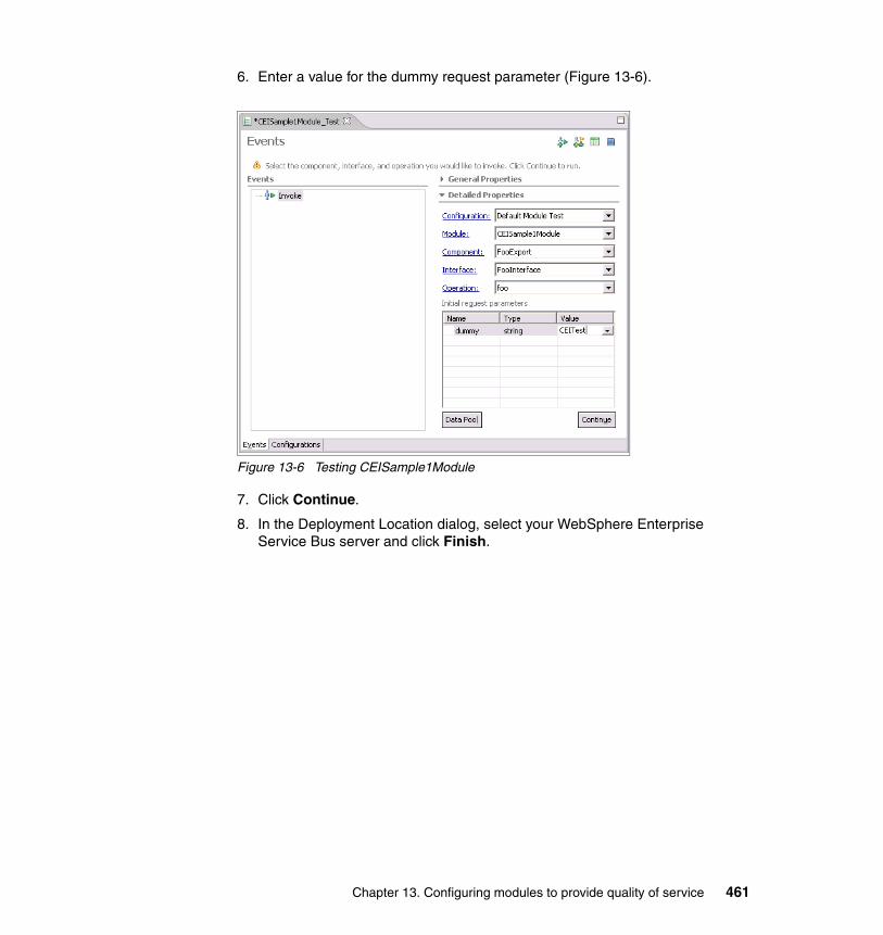
6. Enter a value for the dummy request parameter (Figure 13-6).
Figure 13-6 Testing CEISample1Module
7. Click Continue.
8. In the Deployment Location dialog, select your WebSphere Enterprise Service Bus server and click Finish.
Chapter 13. Configuring modules to provide quality of service 461
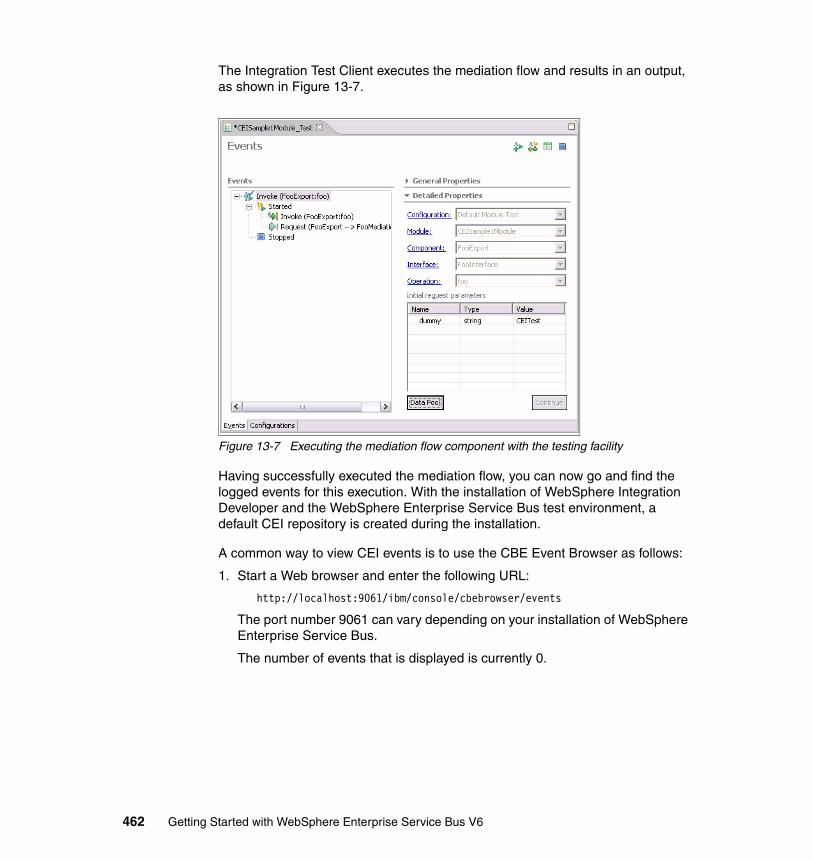
The Integration Test Client executes the mediation flow and results in an output, as shown in Figure 13-7.
Figure 13-7 Executing the mediation flow component with the testing facility
Having successfully executed the mediation flow, you can now go and find the logged events for this execution. With the installation of WebSphere Integration Developer and the WebSphere Enterprise Service Bus test environment, a default CEI repository is created during the installation.
A common way to view CEI events is to use the CBE Event Browser as follows:
1. Start a Web browser and enter the following URL:
http://localhost:9061/ibm/console/cbebrowser/events
The port number 9061 can vary depending on your installation of WebSphere Enterprise Service Bus.
The number of events that is displayed is currently 0.
462 Getting Started with WebSphere Enterprise Service Bus V6
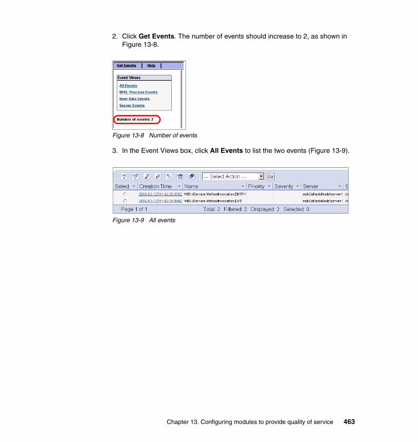
2. Click Get Events. The number of events should increase to 2, as shown in Figure 13-8.
Figure 13-8 Number of events
3. In the Event Views box, click All Events to list the two events (Figure 13-9).
Figure 13-9 All events
Chapter 13. Configuring modules to provide quality of service 463
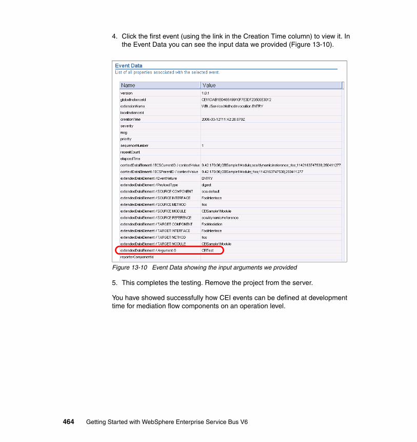
4. Click the first event (using the link in the Creation Time column) to view it. In the Event Data you can see the input data we provided (Figure 13-10).
Figure 13-10 Event Data showing the input arguments we provided
5. This completes the testing. Remove the project from the server.
You have showed successfully how CEI events can be defined at development time for mediation flow components on an operation level.
464 Getting Started with WebSphere Enterprise Service Bus V6
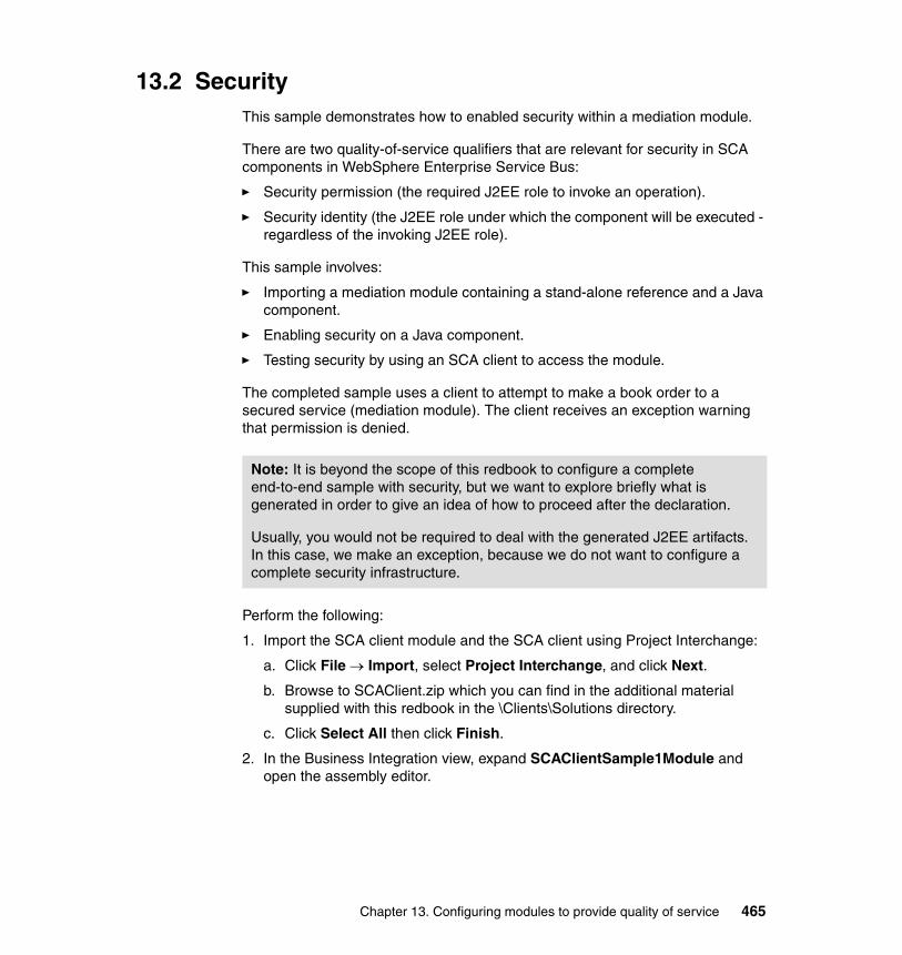
13.2 SecurityThis sample demonstrates how to enabled security within a mediation module.
There are two quality-of-service qualifiers that are relevant for security in SCA components in WebSphere Enterprise Service Bus:
� Security permission (the required J2EE role to invoke an operation).
� Security identity (the J2EE role under which the component will be executed - regardless of the invoking J2EE role).
This sample involves:
� Importing a mediation module containing a stand-alone reference and a Java component.
� Enabling security on a Java component.
� Testing security by using an SCA client to access the module.
The completed sample uses a client to attempt to make a book order to a secured service (mediation module). The client receives an exception warning that permission is denied.
Perform the following:
1. Import the SCA client module and the SCA client using Project Interchange:
a. Click File → Import, select Project Interchange, and click Next.
b. Browse to SCAClient.zip which you can find in the additional material supplied with this redbook in the \Clients\Solutions directory.
c. Click Select All then click Finish.
2. In the Business Integration view, expand SCAClientSample1Module and open the assembly editor.
Note: It is beyond the scope of this redbook to configure a complete end-to-end sample with security, but we want to explore briefly what is generated in order to give an idea of how to proceed after the declaration.
Usually, you would not be required to deal with the generated J2EE artifacts. In this case, we make an exception, because we do not want to configure a complete security infrastructure.
Chapter 13. Configuring modules to provide quality of service 465
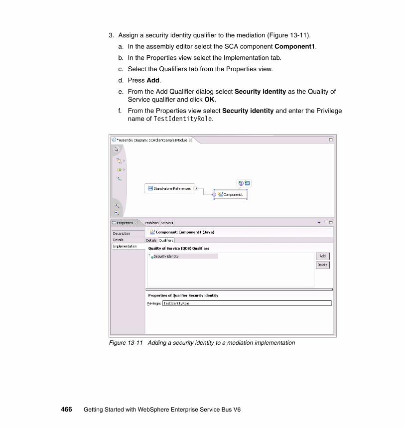
3. Assign a security identity qualifier to the mediation (Figure 13-11).
a. In the assembly editor select the SCA component Component1.
b. In the Properties view select the Implementation tab.
c. Select the Qualifiers tab from the Properties view.
d. Press Add.
e. From the Add Qualifier dialog select Security identity as the Quality of Service qualifier and click OK.
f. From the Properties view select Security identity and enter the Privilege name of TestIdentityRole.
Figure 13-11 Adding a security identity to a mediation implementation
466 Getting Started with WebSphere Enterprise Service Bus V6
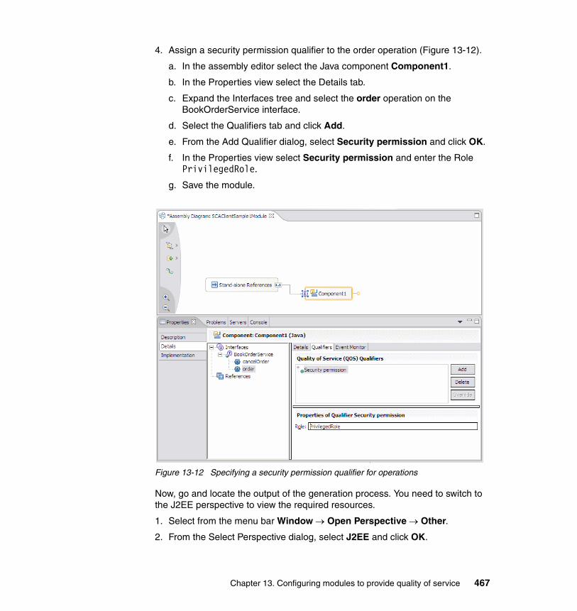
4. Assign a security permission qualifier to the order operation (Figure 13-12).
a. In the assembly editor select the Java component Component1.
b. In the Properties view select the Details tab.
c. Expand the Interfaces tree and select the order operation on the BookOrderService interface.
d. Select the Qualifiers tab and click Add.
e. From the Add Qualifier dialog, select Security permission and click OK.
f. In the Properties view select Security permission and enter the Role PrivilegedRole.
g. Save the module.
Figure 13-12 Specifying a security permission qualifier for operations
Now, go and locate the output of the generation process. You need to switch to the J2EE perspective to view the required resources.
1. Select from the menu bar Window → Open Perspective → Other.
2. From the Select Perspective dialog, select J2EE and click OK.
Chapter 13. Configuring modules to provide quality of service 467
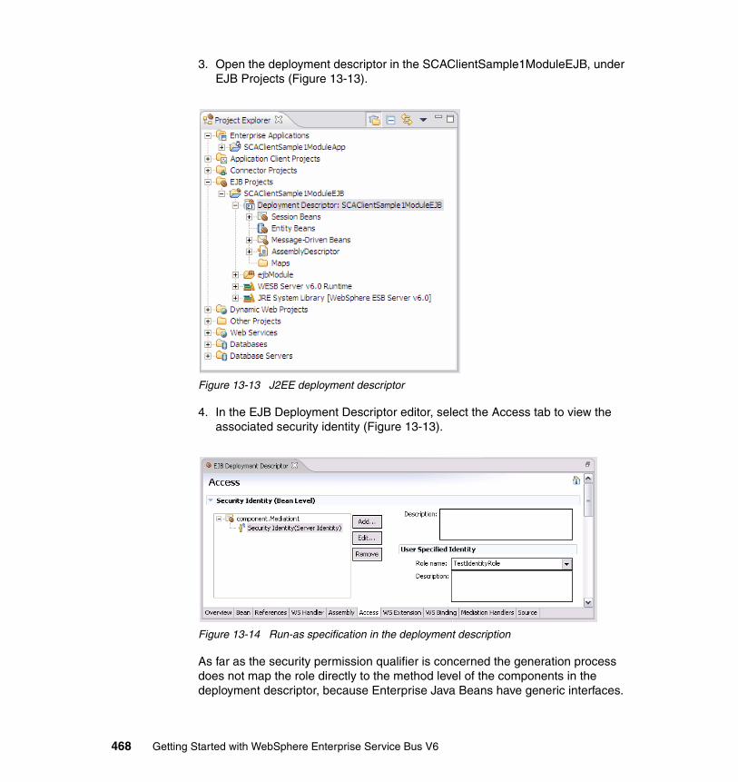
3. Open the deployment descriptor in the SCAClientSample1ModuleEJB, under EJB Projects (Figure 13-13).
Figure 13-13 J2EE deployment descriptor
4. In the EJB Deployment Descriptor editor, select the Access tab to view the associated security identity (Figure 13-13).
Figure 13-14 Run-as specification in the deployment description
As far as the security permission qualifier is concerned the generation process does not map the role directly to the method level of the components in the deployment descriptor, because Enterprise Java Beans have generic interfaces.
468 Getting Started with WebSphere Enterprise Service Bus V6
Therefore, only a role reference gets generated, which is verified in the generated code. Example 13-1 shows the relevant part of the deployment descriptor source.
Example 13-1 Generated J2EE role reference in the deployment descriptor
...<security-role-ref>
<description>PrivilegedRole</description><role-name>PrivilegedRole</role-name><role-link>PrivilegedRole</role-link>
</security-role-ref></session>...
5. Deploy the module to the server.
a. Switch to the Servers view.
b. Right-click your WebSphere Enterprise Service Bus server and select Add and remove projects.
c. Add SCAClientSample1Module.
d. Click Finish.
To test the security, you must enable global security on WebSphere Enterprise Service Bus server as follows:
1. In the Servers view, right-click the WebSphere Enterprise Service Bus server and select Run administrative console.
2. Log into the console.
3. Click Security → Global Security.
4. Under User Registries click Local OS.
5. Enter a user ID and password for accessing the server.
6. Click OK. You are returned to the Global Security properties panel.
7. Under Authentication, expand JAAS configuration and click J2C Authentication data.
Note: The user name and password that you enter must be the user name and password that you used to log onto the server.
Chapter 13. Configuring modules to provide quality of service 469
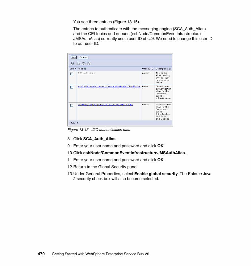
You see three entries (Figure 13-15).
The entries to authenticate with the messaging engine (SCA_Auth_Alias) and the CEI topics and queues (esbNode/CommonEventInfrastructureJMSAuthAlias) currently use a user ID of wid. We need to change this user ID to our user ID.
Figure 13-15 J2C authentication data
8. Click SCA_Auth_Alias.
9. Enter your user name and password and click OK.
10.Click esbNode/CommonEventInfrastructureJMSAuthAlias.
11.Enter your user name and password and click OK.
12.Return to the Global Security panel.
13.Under General Properties, select Enable global security. The Enforce Java 2 security check box will also become selected.
470 Getting Started with WebSphere Enterprise Service Bus V6
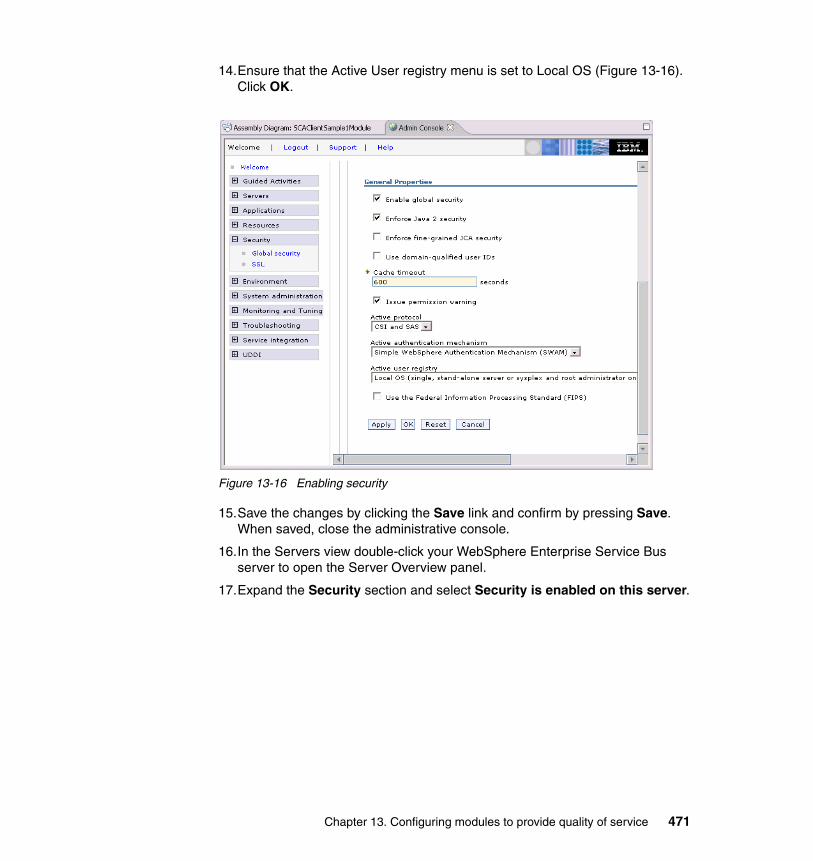
14.Ensure that the Active User registry menu is set to Local OS (Figure 13-16). Click OK.
Figure 13-16 Enabling security
15.Save the changes by clicking the Save link and confirm by pressing Save. When saved, close the administrative console.
16.In the Servers view double-click your WebSphere Enterprise Service Bus server to open the Server Overview panel.
17.Expand the Security section and select Security is enabled on this server.
Chapter 13. Configuring modules to provide quality of service 471
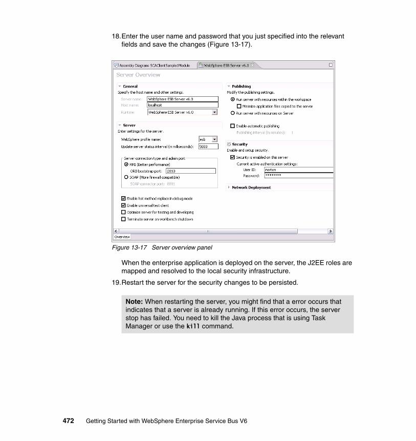
18.Enter the user name and password that you just specified into the relevant fields and save the changes (Figure 13-17).
Figure 13-17 Server overview panel
When the enterprise application is deployed on the server, the J2EE roles are mapped and resolved to the local security infrastructure.
19.Restart the server for the security changes to be persisted.
Note: When restarting the server, you might find that a error occurs that indicates that a server is already running. If this error occurs, the server stop has failed. You need to kill the Java process that is using Task Manager or use the kill command.
472 Getting Started with WebSphere Enterprise Service Bus V6
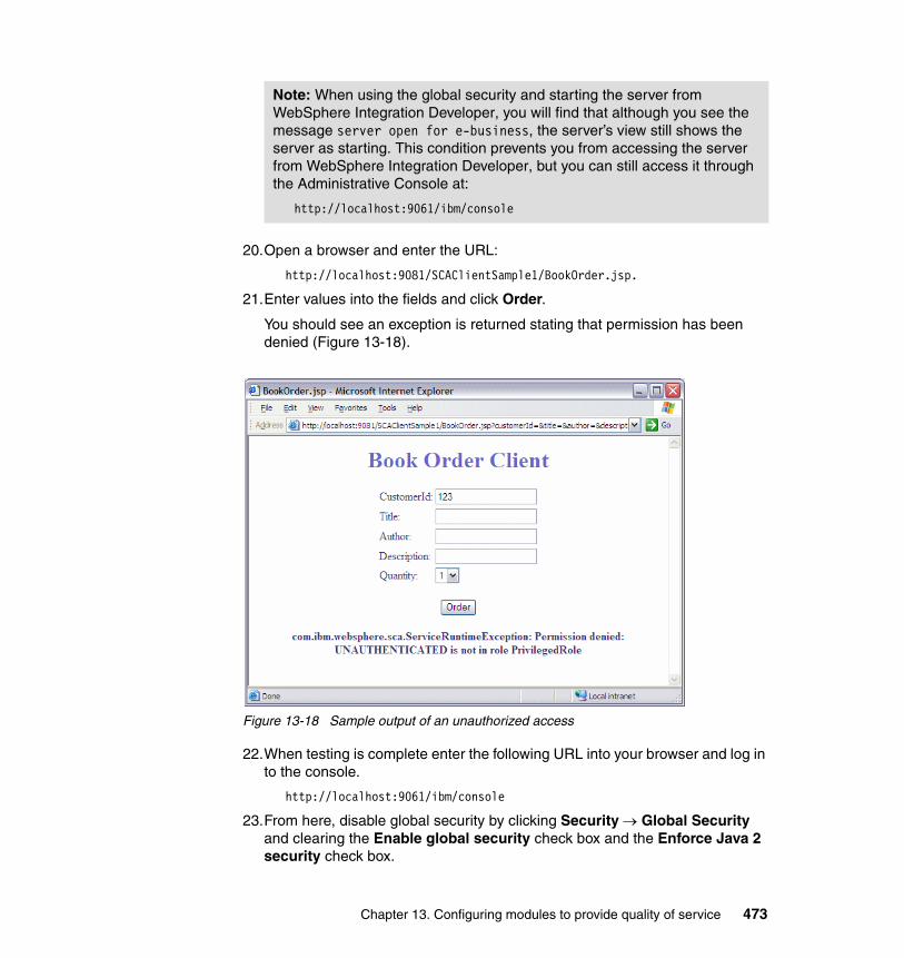
20.Open a browser and enter the URL:
http://localhost:9081/SCAClientSample1/BookOrder.jsp.
21.Enter values into the fields and click Order.
You should see an exception is returned stating that permission has been denied (Figure 13-18).
Figure 13-18 Sample output of an unauthorized access
22.When testing is complete enter the following URL into your browser and log in to the console.
http://localhost:9061/ibm/console
23.From here, disable global security by clicking Security → Global Security and clearing the Enable global security check box and the Enforce Java 2 security check box.
Note: When using the global security and starting the server from WebSphere Integration Developer, you will find that although you see the message server open for e-business, the server’s view still shows the server as starting. This condition prevents you from accessing the server from WebSphere Integration Developer, but you can still access it through the Administrative Console at:
http://localhost:9061/ibm/console
Chapter 13. Configuring modules to provide quality of service 473
24.Click OK and save the changes.
25.In WebSphere Integration Developer in the Servers view, double-click your WebSphere Enterprise Service Bus server. Expand Security and clear Security is enabled on this server. Save and close the editor.
26.Restart the server and remove the deployed module.
You have successfully demonstrated how to enable security on a mediation module.
For more informationFor more information, consult the following sources:
� For a detailed walkthrough (including authentication) on the application of security qualifiers see the following article:
Defining a J2EE role on Service Component Architecture components with WebSphere Integration Developer 6.0.1
http://www-128.ibm.com/developerworks/websphere/library/techarticles/0602_charpentier/0602_charpentier.html
� For more information about the security model of WebSphere Process Server (mostly applicable to WebSphere Enterprise Service Bus):
WebSphere Process Server security overview
http://www-128.ibm.com/developerworks/websphere/library/techarticles/0602_khangoankar/0602_khangaonkar.html
� For general information about J2EE security in WebSphere Application Server V6 and how to set up security, refer to WebSphere Application Server V6 Security Handbook, SG24-6316.
13.3 TransactionsThis sample shows how to control transactional behavior in mediation modules and mediation primitives.
A transaction is used to group units of work together. If an exception occurs during a transaction every unit of work performed within that transaction will be rolled-back, otherwise they are all committed.
474 Getting Started with WebSphere Enterprise Service Bus V6
This sample involves:
� Importing a mediation module.� Specifying transaction qualifiers on a mediation module.� Defining transaction scope on a Message Logger mediation primitive.� Testing a completed transaction.� Testing a rolled-back transaction.� Viewing whether messages where logged to a Cloudscape database.
The completed sample demonstrates ordering a book. In one instance, the order is successful and a confirmation ID is returned. In the other case, the transaction is rolled-back, and no confirmation ID is returned.
Follow these steps:
1. Import existing resources:
a. From the menu bar, select File → Import. Click Project Interchange and click Next.
b. Browse to TransactionSampleResources.zip, which is located in the additional material that is supplied with this redbook in the \QualityOfService\Resources\Transactions directory.
c. Click Select All then click Finish.
d. Switch to the J2EE perspective
i. From the menu bar, select Window → Open Perspective → Other.
ii. Select J2EE and click OK.
e. Expand the EJB Projects folder.
f. You will see an error on the SCATranSample1EJB project.
g. Expand SCATranSample1EJB → Deployment Descriptor → Session Beans.
h. Right-click Default Session and select Deploy to resolve the error.
2. Review the transaction settings of TransactionSample1Module.
a. Switch back to the Business Integration perspective.
b. Open the Assembly Diagram of TransactionSample1Module using .
c. Select Stand-alone References. In the Properties view, select the Qualifiers tab.
Note: Rather than building modules from scratch, we concentrate on reviewing the transaction settings and testing the transactional behavior.
Chapter 13. Configuring modules to provide quality of service 475
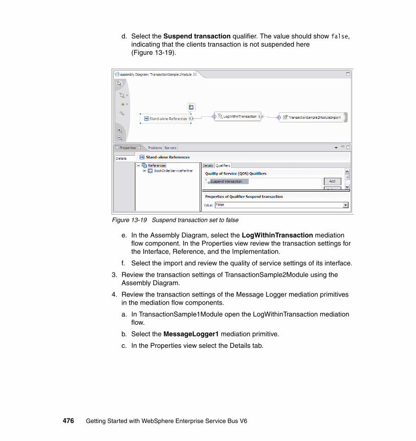
d. Select the Suspend transaction qualifier. The value should show false, indicating that the clients transaction is not suspended here (Figure 13-19).
Figure 13-19 Suspend transaction set to false
e. In the Assembly Diagram, select the LogWithinTransaction mediation flow component. In the Properties view review the transaction settings for the Interface, Reference, and the Implementation.
f. Select the import and review the quality of service settings of its interface.
3. Review the transaction settings of TransactionSample2Module using the Assembly Diagram.
4. Review the transaction settings of the Message Logger mediation primitives in the mediation flow components.
a. In TransactionSample1Module open the LogWithinTransaction mediation flow.
b. Select the MessageLogger1 mediation primitive.
c. In the Properties view select the Details tab.
476 Getting Started with WebSphere Enterprise Service Bus V6
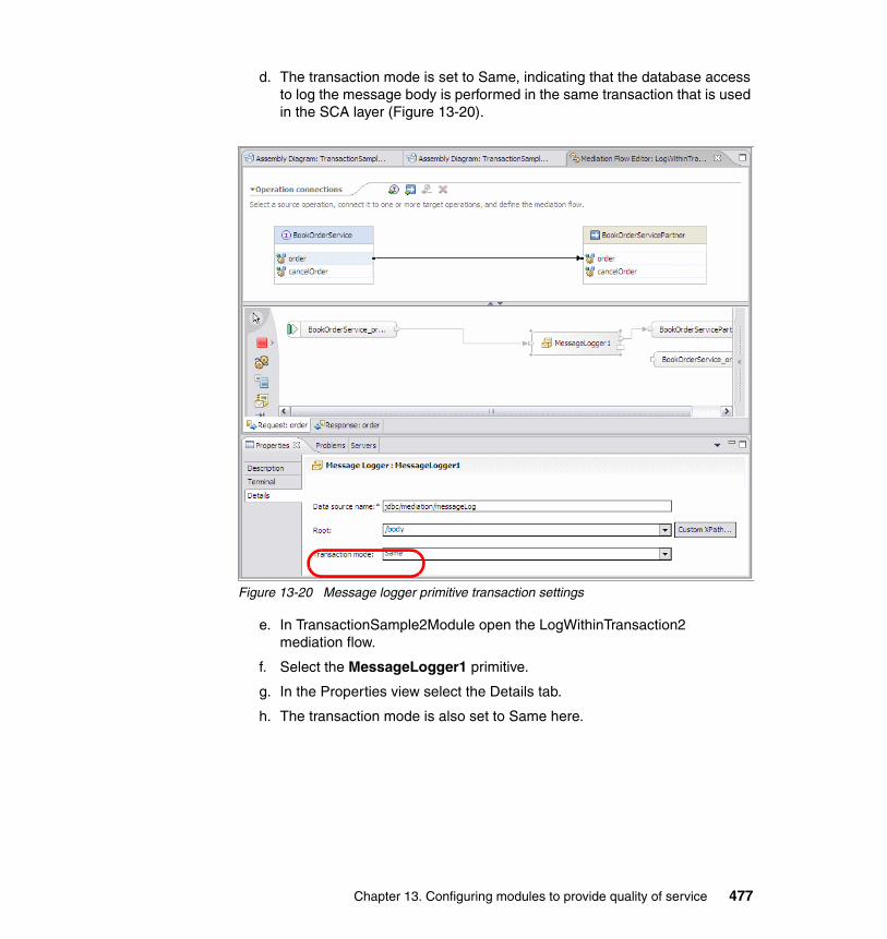
d. The transaction mode is set to Same, indicating that the database access to log the message body is performed in the same transaction that is used in the SCA layer (Figure 13-20).
Figure 13-20 Message logger primitive transaction settings
e. In TransactionSample2Module open the LogWithinTransaction2 mediation flow.
f. Select the MessageLogger1 primitive.
g. In the Properties view select the Details tab.
h. The transaction mode is also set to Same here.
Chapter 13. Configuring modules to provide quality of service 477
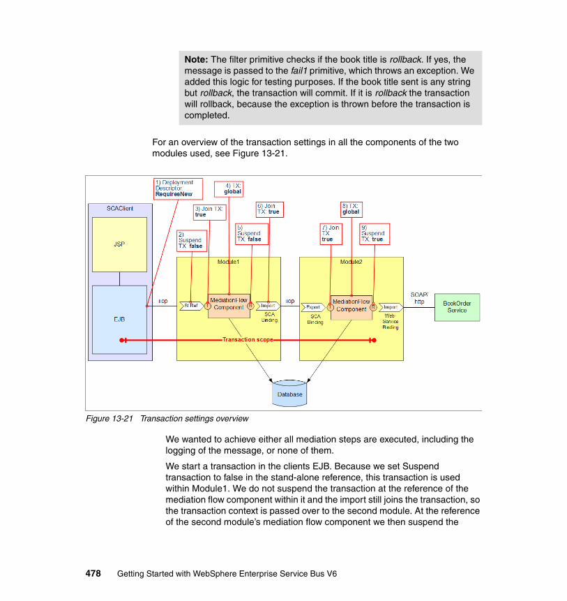
For an overview of the transaction settings in all the components of the two modules used, see Figure 13-21.
Figure 13-21 Transaction settings overview
We wanted to achieve either all mediation steps are executed, including the logging of the message, or none of them.
We start a transaction in the clients EJB. Because we set Suspend transaction to false in the stand-alone reference, this transaction is used within Module1. We do not suspend the transaction at the reference of the mediation flow component within it and the import still joins the transaction, so the transaction context is passed over to the second module. At the reference of the second module’s mediation flow component we then suspend the
Note: The filter primitive checks if the book title is rollback. If yes, the message is passed to the fail1 primitive, which throws an exception. We added this logic for testing purposes. If the book title sent is any string but rollback, the transaction will commit. If it is rollback the transaction will rollback, because the exception is thrown before the transaction is completed.
478 Getting Started with WebSphere Enterprise Service Bus V6
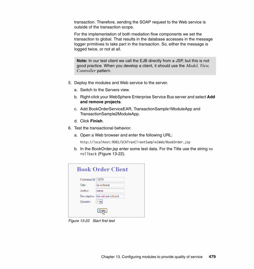
transaction. Therefore, sending the SOAP request to the Web service is outside of the transaction scope.
For the implementation of both mediation flow components we set the transaction to global. That results in the database accesses in the message logger primitives to take part in the transaction. So, either the message is logged twice, or not at all.
5. Deploy the modules and Web service to the server.
a. Switch to the Servers view.
b. Right-click your WebSphere Enterprise Service Bus server and select Add and remove projects.
c. Add BookOrderServiceEAR, TransactionSample1ModuleApp and TransactionSample2ModuleApp.
d. Click Finish.
6. Test the transactional behavior.
a. Open a Web browser and enter the following URL:
http://localhost:9081/SCATranClientSample1Web/BookOrder.jsp
b. In the BookOrder.jsp enter some test data. For the Title use the string no rollback (Figure 13-22).
Figure 13-22 Start first test
Note: In our test client we call the EJB directly from a JSP, but this is not good practice. When you develop a client, it should use the Model, View, Controller pattern.
Chapter 13. Configuring modules to provide quality of service 479
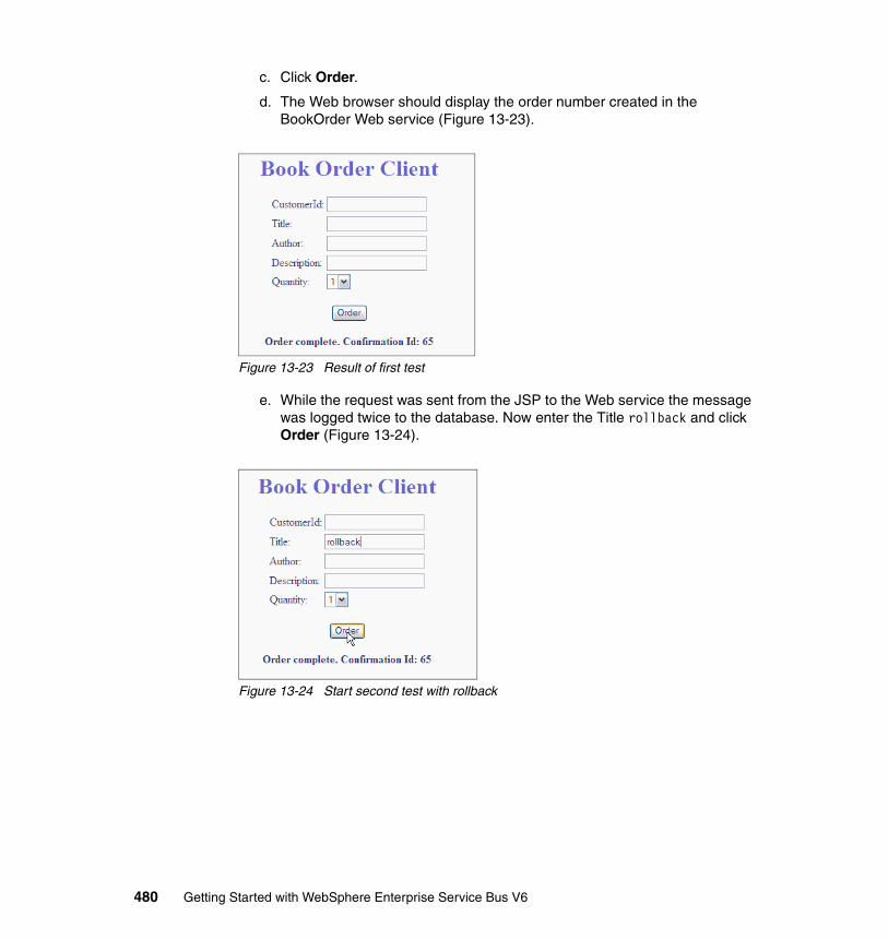
c. Click Order.
d. The Web browser should display the order number created in the BookOrder Web service (Figure 13-23).
Figure 13-23 Result of first test
e. While the request was sent from the JSP to the Web service the message was logged twice to the database. Now enter the Title rollback and click Order (Figure 13-24).
Figure 13-24 Start second test with rollback
480 Getting Started with WebSphere Enterprise Service Bus V6
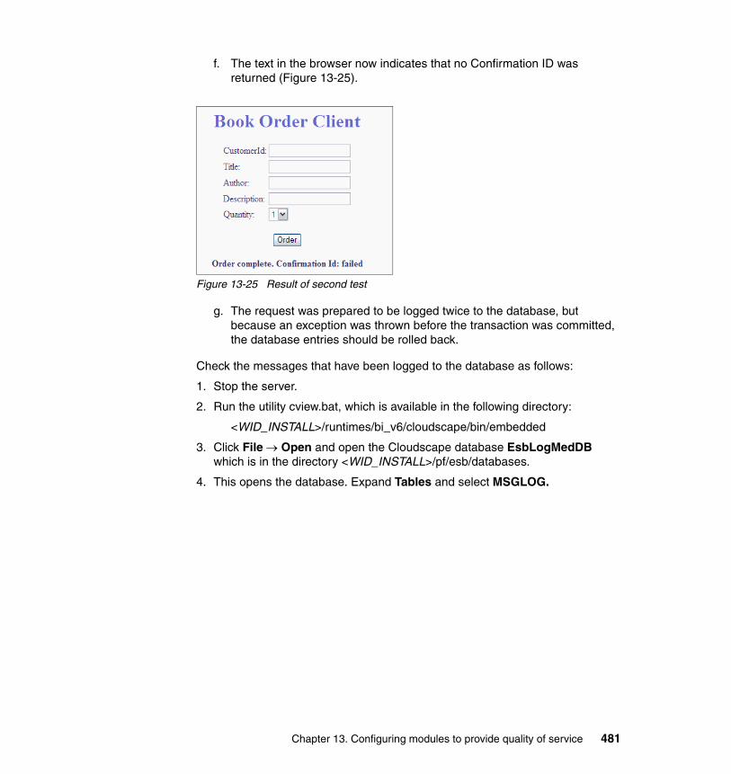
f. The text in the browser now indicates that no Confirmation ID was returned (Figure 13-25).
Figure 13-25 Result of second test
g. The request was prepared to be logged twice to the database, but because an exception was thrown before the transaction was committed, the database entries should be rolled back.
Check the messages that have been logged to the database as follows:
1. Stop the server.
2. Run the utility cview.bat, which is available in the following directory:
<WID_INSTALL>/runtimes/bi_v6/cloudscape/bin/embedded
3. Click File → Open and open the Cloudscape database EsbLogMedDB which is in the directory <WID_INSTALL>/pf/esb/databases.
4. This opens the database. Expand Tables and select MSGLOG.
Chapter 13. Configuring modules to provide quality of service 481
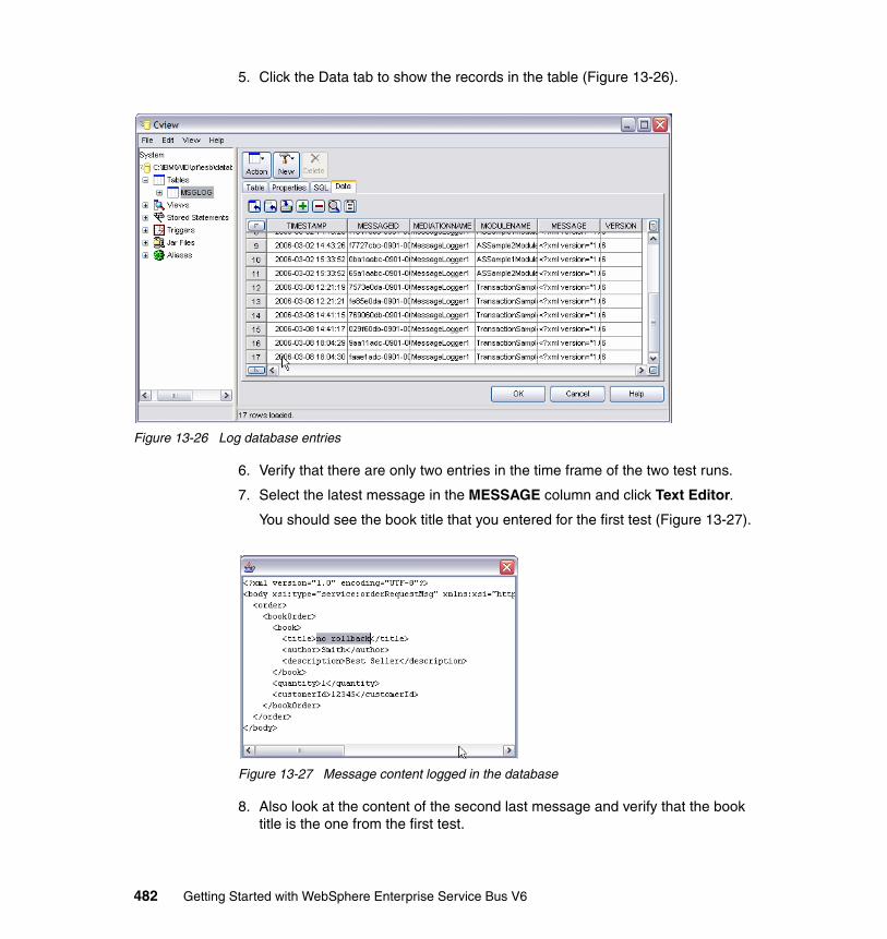
5. Click the Data tab to show the records in the table (Figure 13-26).
Figure 13-26 Log database entries
6. Verify that there are only two entries in the time frame of the two test runs.
7. Select the latest message in the MESSAGE column and click Text Editor.
You should see the book title that you entered for the first test (Figure 13-27).
Figure 13-27 Message content logged in the database
8. Also look at the content of the second last message and verify that the book title is the one from the first test.
482 Getting Started with WebSphere Enterprise Service Bus V6
9. Close the cview.bat utility.
10.Start the server and remove all projects from the server.
Note: The request message from the second test were also prepared to be written to the database twice. However, because the log primitives participate in the global transaction that was started by the client and the transaction was rolled back, they were not written.
Chapter 13. Configuring modules to provide quality of service 483

484 Getting Started with WebSphere Enterprise Service Bus V6
Part 5 Appendixes
Part 5
© Copyright IBM Corp. 2006. All rights reserved. 485

486 Getting Started with WebSphere Enterprise Service Bus V6
Appendix A. Additional material
This appendix describes how to download the additional material referred to in this redbook.
Locating the Web materialThe Web material that is associated with this redbook is available in softcopy on the Internet from the IBM Redbooks Web server. Point your Web browser to:
ftp://www.redbooks.ibm.com/redbooks/SG247212
Alternatively, you can go to the IBM Redbooks Web site at:
ibm.com/redbooks
Select Additional materials and open the directory that corresponds with the redbook form number, SG247217.
A
© Copyright IBM Corp. 2006. All rights reserved. 487
Using the Web materialThe additional Web material that accompanies this redbook includes the following files:
File name DescriptionSG247212.zip Zipped Code Samples
This zipped file contains all of the resources that are required to complete the development examples in this redbook. It contains resources that you need to import for certain development examples within this redbook. It also contains solutions to each development example, which are stored in Project Interchange ZIP files.
How to use the Web materialCreate a subdirectory (folder) on your workstation, and unzip the contents of the Web material zipped file into this folder.
488 Getting Started with WebSphere Enterprise Service Bus V6
Appendix B. Hints and tips
This appendix lists a few obstacles that we ran into while creating the samples for this redbook. It also includes the workarounds for these obstacles. You might not necessarily observe these behaviors in subsequent releases of the product. It covers the following hints:
� Force complete regeneration� Update of business objects� Renaming of resources� Testing of a mediation flow component stand-alone� Incompatible target runtimes
B
© Copyright IBM Corp. 2006. All rights reserved. 489
Resolving obstacles with WebSphere Integration Developer
Each hint in this section describes the scenario where we encountered an issue, where the behavior occurred, and how we resolved the issue.
Force complete regenerationYou have developed a module and added the project to the server.
Observed behaviorYou observe a stack trace in the Console view when executing the mediation module warning that a WSDL file cannot be found.
ResolutionTo resolve this issue, force a clean regeneration and deployment:
1. Remove the project from the server.2. Run a project clean (Project → Clean).3. Add the project again to the server.
Update of business objectsYou have developed a module and added the project to the server. Now you change the business objects used by the module (for example, you add attributes).
Observed behaviorThe changes are not reflected in your test environment even if you redeploy the project.
ResolutionThe objects are cached, so you need to restart the server.
Note: In some cases, you might need to stop the server after step 1 and start the server after step 2.
490 Getting Started with WebSphere Enterprise Service Bus V6
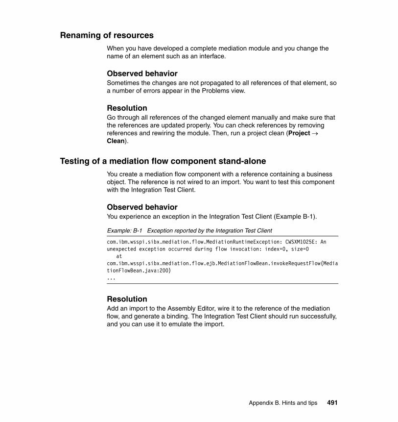
Renaming of resources When you have developed a complete mediation module and you change the name of an element such as an interface.
Observed behaviorSometimes the changes are not propagated to all references of that element, so a number of errors appear in the Problems view.
ResolutionGo through all references of the changed element manually and make sure that the references are updated properly. You can check references by removing references and rewiring the module. Then, run a project clean (Project → Clean).
Testing of a mediation flow component stand-aloneYou create a mediation flow component with a reference containing a business object. The reference is not wired to an import. You want to test this component with the Integration Test Client.
Observed behaviorYou experience an exception in the Integration Test Client (Example B-1).
Example: B-1 Exception reported by the Integration Test Client
com.ibm.wsspi.sibx.mediation.flow.MediationRuntimeException: CWSXM1025E: An unexpected exception occurred during flow invocation: index=0, size=0
at com.ibm.wsspi.sibx.mediation.flow.ejb.MediationFlowBean.invokeRequestFlow(MediationFlowBean.java:200)...
ResolutionAdd an import to the Assembly Editor, wire it to the reference of the mediation flow, and generate a binding. The Integration Test Client should run successfully, and you can use it to emulate the import.
Appendix B. Hints and tips 491
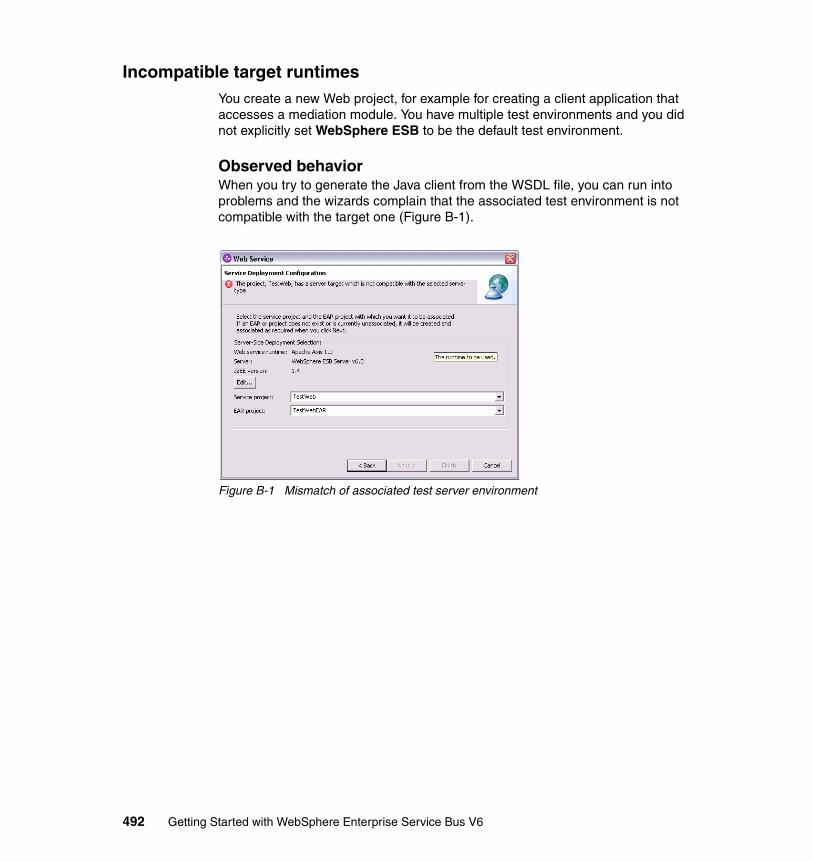
Incompatible target runtimesYou create a new Web project, for example for creating a client application that accesses a mediation module. You have multiple test environments and you did not explicitly set WebSphere ESB to be the default test environment.
Observed behaviorWhen you try to generate the Java client from the WSDL file, you can run into problems and the wizards complain that the associated test environment is not compatible with the target one (Figure B-1).
Figure B-1 Mismatch of associated test server environment
492 Getting Started with WebSphere Enterprise Service Bus V6
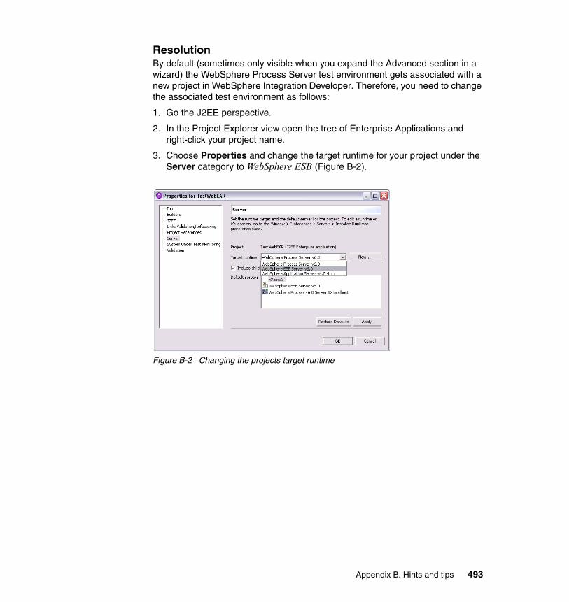
ResolutionBy default (sometimes only visible when you expand the Advanced section in a wizard) the WebSphere Process Server test environment gets associated with a new project in WebSphere Integration Developer. Therefore, you need to change the associated test environment as follows:
1. Go the J2EE perspective.
2. In the Project Explorer view open the tree of Enterprise Applications and right-click your project name.
3. Choose Properties and change the target runtime for your project under the Server category to WebSphere ESB (Figure B-2).
Figure B-2 Changing the projects target runtime
Appendix B. Hints and tips 493

494 Getting Started with WebSphere Enterprise Service Bus V6
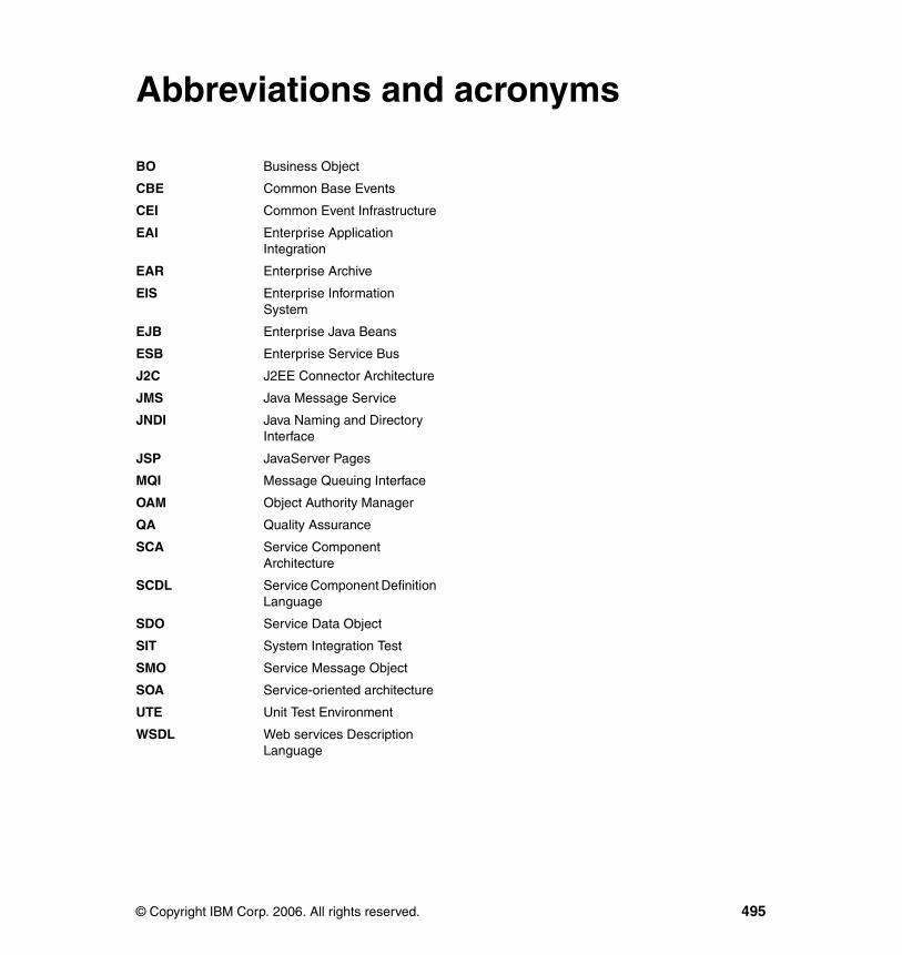
acronyms
BO Business Object
CBE Common Base Events
CEI Common Event Infrastructure
EAI Enterprise Application Integration
EAR Enterprise Archive
EIS Enterprise Information System
EJB Enterprise Java Beans
ESB Enterprise Service Bus
J2C J2EE Connector Architecture
JMS Java Message Service
JNDI Java Naming and Directory Interface
JSP JavaServer Pages
MQI Message Queuing Interface
OAM Object Authority Manager
QA Quality Assurance
SCA Service Component Architecture
SCDL Service Component Definition Language
SDO Service Data Object
SIT System Integration Test
SMO Service Message Object
SOA Service-oriented architecture
UTE Unit Test Environment
WSDL Web services Description Language
Abbreviations and
© Copyright IBM Corp. 2006. All rights reserved.
495
496 Getting Started with WebSphere Enterprise Service Bus V6

Related publications
This section lists publications that are considered particularly suitable for a more detailed discussion of the topics that this redbook discusses.
IBM RedbooksFor information about ordering these publications, see “How to get IBM Redbooks” on page 498. Note that some of the documents referenced here might be available in softcopy only.
� Rational Application Developer V6 Programming Guide, SG24-6449
� WebSphere Version 6 Web Services Handbook Development and Deployment, SG24-6461
� WebSphere Application Server V6 System Management & Configuration Handbook, SG24-6451
� WebSphere Application Server Network Deployment V6: High Availability Solutions, SG24-6688
� WebSphere Application Server V6 Security Handbook, SG24-6316
Other publicationsThese publications are also relevant as further information sources:
� Patterns for e-business: A Strategy for Reuse, by Jonathan Adams, Srinivas Koushik, Guru Vasudeva, and George Galambos, ISBN 1931182027
© Copyright IBM Corp. 2006. All rights reserved. 497
Online resourcesThese Web sites and URLs are also relevant as further information sources:
� WebSphere Enterprise Service Bus home page:
http://www.ibm.com/software/integration/wsesb/
� WebSphere Application Server home page:
http://www.ibm.com/software/webservers/appserv/was/
� WebSphere Process Server home page:
http://www.ibm.com/software/integration/wps/
� WebSphere MQ home page:
http://www.ibm.com/software/integration/wmq/
� WebSphere Message Broker home page:
http://www.ibm.com/software/integration/wbimessagebroker/v6/
How to get IBM RedbooksYou can search for, view, or download Redbooks, Redpapers, Hints and Tips, draft publications and Additional materials, as well as order hardcopy Redbooks or CD-ROMs, at this Web site:
ibm.com/redbooks
Help from IBMIBM Support and downloads
ibm.com/support
IBM Global Services
ibm.com/services
498 Getting Started with WebSphere Enterprise Service Bus V6
Index
AActivity Sessions 153Adapters 46Administration 261Administration console 262Application developer 53Application server 33Assemble mediations 60assembly diagram 27–28Asynchronous reliability 154
BBinding 148Binding type 38Bindings 84
EIS binding 291, 303JMS binding 290, 325JMS bindings 348JMS custom binding 290SCA binding 295SCA bindings 290SOAP/HTTP binding 348Web service binding 290, 361, 372, 394, 416, 424
Breakpoint 403Broker 44Building and cleaning projects 207Business Integration perspective 77Business object 41, 348Business object map 42Business Objects 184
Attributes 185Creating 184Deriving 189Supersets 188
business problem 23–24Business process 41Business rule 42business service 24
universal model 24Business state machine 42
© Copyright IBM Corp. 2006. All rights reserved.
CCBE Event Browser 257, 456CEI 456CEI repository 462CICS 303CICS Transaction Gateway 304Client container 34Clients 39
JMS 325SCA 341Web services 318
Cloudscape 394, 419, 456, 475Commarea 304Common Base Event 37, 155Common Event Infrastructure 37, 456, 474common event infrastructure 155CommonEventInfrastructure _Bus 97Communication 22Configuration manager 45Correlation context 361, 367, 406Custom node 99Custom profile 121CVS repository 77CVS Repository Exploring perspective 76–77CVS server 77CVS source code management system 76
Ddata graph 29
See also business graphdata object 28Database 394, 415database 456Default configuration 63Default terminal 410DefaultESBServer template 127Deployment 156
J2EE staging projects 156Development environment 52Distribution mode 411, 415dynamic
Web services 14
499

Ee-business 14Editors 169
Assembly Diagram 169Business Object 170Interface 170Visual Java snippet 171
EJB container 34Emulate 234Emulation 391Enabling security 465Enterprise Information System (EIS) 24Enterprise Service Bus
CapabilitiesCommunication 22Infrastructure Intelligence 23Integration 22Management and Autonomic 23Message Processing 23Modeling 23Quality of Service 22Security 22Service Interaction 22Service Level 22
Mediate 19Minimum capability
Heterogeneous infrastructure 20Integration 20Logical architectural component 20Manage the service infrastructure 20Management and Autonomic 20Service Interaction 20
Substitution 19Transform 19
Enterprise Service Discovery wizard 303ESB
ESB products 33ESBSamplesGallery 92Event driven architectures 19Event logging 456Event Monitor 456Exception 371Exceptions 424Execution group 45Export 37, 295Exporting resources 224
Enterprise Applications 226Project Interchange 225
Exports 173
Creating 202exports 273Extensible Markup Language
see XML
FFailFlowException 432Fault condition 372, 379Fault data 379Fault handling 371Fault message 372Fault terminal 424Faults 371First Steps 111
GGetting Started Guide 105
HHelper dialog 102High availability 35Human task 42
IIBM SOA reference architecture 32Import 37, 295Imports 174
Creating 204imports 273IMS 312Infrastructure Intelligence 23Install fixes 71Install Updates 73Installation 61
Complete 91Custom 91Silent 62
Installation directory 61Installation verification 111Installation wizard 61, 91Integrated Development Environment 65Integrated Test Environment 66Integration 22Integration Debugger 243Integration developer 53Integration specialist 85Integration Test Client 291, 295, 348, 368, 377,
500 Getting Started with WebSphere Enterprise Service Bus V6

382, 394, 406, 416, 424, 432, 440, 456Integration test client 230Interface 141, 348, 371Interface map 42Interfaces 180
Adding one way operations 192Adding request response operations 193Defining 191Importing 180
interoperable 14
JJ2EE roles 472Java class 24
preferred form 24Java component 295, 341, 407Java Message Service (JMS) 43Java Messaging Service 325JavaMail 440JCA connector 303JMS 325JMS bindings 266JMS resources 325JSP 336, 342
KKey 394, 400Key technologies 7Key terms 138KeyNotFound 400
Llanguage-independent 14Launchpad 63Library 163
Adding to module 182Creating 182
listSCAExports 274listSCAImports 274listSCAModules 272Log 361, 416loosely coupled 14
MManage mediation modules 262Management and Autonomic 23Mapping 366
Mediate 19Mediation 139
Mediation base 37Mediation flow component 37Mediation functions 37Mediation module 37Mediation primitives 38
Mediation flow 142Callout 143Callout response 143Input 143Input fault 143Input response 143Request flow 142Response flow 142
Mediation Flow component 137, 141Interface 141Partner reference 141Wiring 141
Mediation flow component 372, 394, 424, 432Mediation flow components 174
Creating 196Implementing 198
Mediation module 140, 291, 295, 318, 341, 348, 361, 372, 382, 394, 406, 416, 424, 432, 440, 456, 465, 475Mediation modules 84Mediation primitive 144
Fault terminal 145Input terminal 145Output terminal 145
Mediation primitives 175, 361, 474Adding 199Custom 439Database Lookup 394Fail 432Message Filter 406Message Logger 415Properties 201Stop 424, 456XSL Transformation 382
MediationsMessage Logger 361XSL Transformation 361
Message brokers toolkit 45Message driven architectures 19Message flow 44Message Processing 23Message Queuing Interface (MQI) 43
Index 501
messaging provider 33Modeling 23modifySCAImportSCABinding 278modular 14Module 163
Mediation module 171Creating 194Running 207
ModulesMediation modules
Testing 224
NNetwork Deployment 99
OOutput terminal 410
PPartner reference 141Payload 143Perspectives 163
Business Integration 163Primitives
Message Logger 475Product overview 136Profile Creation Wizard 114Profile Creation wizard 121Profiles 95
augmenting 101programmatic access 14
QQualifiers 475Quality of Service 22, 149, 465
Activity Sessions 153Asynchronous reliability 154Security 150Transactions 153
RRational Application Developer 54Rational Product Updater 69Rational Software Architect 54Rational Software Development Platform 60Rational Web Developer 33Redbooks Web site 498
Contact us xivReference 140Relationship 43Request flow 142, 200, 361Resource adapter 303Response file 61Response flow 142, 201, 361Routing 406Runtime environment 89
SSCA 23SCA client 465SCA component 24
main terms 24SCA Modules 263SCA programming model 341–342SCA.APPLICATION.cell_name.Bus 97SCA.SYSTEM.cell_name.Bus 96SDO
data graph 29data object 28
Security 22, 150, 465Security identity 465Security permission 465Selector 43self-contained 13self-describing 13Servers
Administrative console 221Commands 220Configuration 209Creating 209Debugging 221Deploying 222Local test environments 209Managing 208Profiles 208Remote test environments 209Starting 220Stopping 221
Service component 42Service Component Architecture 23, 36, 60Service consumers 139Service Data Objects 37Service integration bus 40Service Interaction 22Service Level 22
502 Getting Started with WebSphere Enterprise Service Bus V6

Service Message Object 37, 137, 143, 145, 382, 394, 406, 415, 439
Manipulation 148Structure 146
Context section 147Data section 147Header section 147
Service providers 139serviceDeploy 267Service-oriented architecture 19
Component Based Design 9Drivers
Flexible pricing 8Increasing speed 8Reducing costs 8Return on investment 8Simplifying integration 8
Object Oriented development 9Service
Deployment time 10Implementation-independent 10Loosely bound 10Reusable 10Runtime 10
Share Project 77showSCAExport 274showSCAExportBinding 276showSCAImportBinding 275showSCAModule 273Silent installation 62Simple Object Access Protocol
see SOAPSOAP 13SOAP over JMS bindings 266Stand-alone reference 140, 465Stand-alone server 97Supporting service 42
TTeam development 76Team Synchronizing perspective 76Testing security 465Trace settings 255Transaction 439, 474Transaction mode 419Transactional behavior 474Transactions 153Transcode 348
Transform 19Transient context 406Transport protocol 348
UUDDI 13Unit of work 474Unit test server 62Universal Description, Discovery, and Integration
see UDDIUpdate policy 71URI 319User role 52User roles 62
VViews 164
Business Integration 164Business Integration view 291Outline 167Physical Resources 165Problems 168Properties 168References 166Servers 169Visual Snippets 167
WWeb browser 336Web container 34Web service 291, 318, 325, 362, 382, 416, 432, 456Web service bindings 264Web services
core technologies 13Web Services Description Language
see WSDLWeb Services Explorer 235, 303WebSphere Application Server 33WebSphere Application Server - Express 33WebSphere Application Server Network Deploy-ment 34, 261WebSphere Enterprise Service Bus 36, 261
Administration 261WebSphere Integration Developer 54, 60, 159WebSphere Message Broker 44WebSphere MQ 43
Index 503

WebSphere Process Server 41Wiring a mediation flow 200Workbench 161Workload management 35Workspace 162
Capabilities 178Configuration 176Creating 176Shortcuts 177
wrap applications 14wsadmin 263, 272WSDL 13, 293, 295, 314
XXML 13XPath 406, 419XSL mapping 389XSL stylesheets 382
504 Getting Started with WebSphere Enterprise Service Bus V6

(0.5” spine)0.475”<
->0.875”
250 <->
459 pages
Getting Started with W
ebSphere Enterprise Service Bus V6


®
SG24-7212-00 ISBN 073849710X
INTERNATIONAL TECHNICALSUPPORTORGANIZATION
BUILDING TECHNICALINFORMATION BASED ONPRACTICAL EXPERIENCE
IBM Redbooks are developed by the IBM International Technical Support Organization. Experts from IBM, Customers and Partners from around the world create timely technical information based on realistic scenarios. Specific recommendations are provided to help you implement IT solutions more effectively in your environment.
For more information:ibm.com/redbooks
Getting Started with WebSphere Enterprise Service Bus V6Build ESB solutions using SCA and Web services
Implement mediation flows in WebSphere Integration Developer
Learn by example with practical scenarios
IBM WebSphere Enterprise Service Bus is a flexible connectivity infrastructure for integrating applications and services. It is designed to enable the development of a service-oriented architecture (SOA).
This IBM Redbook guides you through the capabilities and product features of WebSphere Enterprise Service Bus V6.0. It also contains step-by-step examples of how to build resources for WebSphere Enterprise Service Bus using WebSphere Integration Developer.
• Part 1 introduces WebSphere Enterprise Service Bus and positions it among other SOA and Enterprise Service Bus product offerings from IBM.
• Part 2 describes how to install and configure both WebSphere Enterprise Service Bus and WebSphere Integration Developer and explains how to perform key concepts and tasks using these products.
• Part 3 explains the administration and testing capabilities, including step-by-step examples.
• Part 4 provides development examples that show step-by-step how to develop solutions using mediation primitives, how to integrate with services, and how to deliver qualities of service.
Back cover