Embed Size (px)
Citation preview
8/12/2019 GF Brochure RevL VeriCal RevC
http://slidepdf.com/reader/full/gf-brochure-revl-verical-revc 1/6
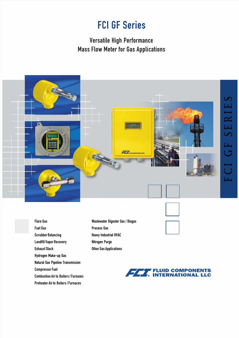
FCI GF Series
Versatile High Performance
Mass Flow Meter for Gas Applications
Flare Gas
Fuel Gas
Scrubber Balancing
Landfill Vapor Recovery
Exhaust Stack
Hydrogen Make-up Gas
Natural Gas Pipeline Transmission
Compressor Fuel
Combustion Air to Boilers / Furnaces
Preheater Air to Boilers / Furnaces
Wastewater Digester Gas / Biogas
Process Gas
Heavy Industrial HVAC
Nitrogen Purge
Other Gas Applications
8/12/2019 GF Brochure RevL VeriCal RevC
http://slidepdf.com/reader/full/gf-brochure-revl-verical-revc 2/6
Reliability, Flexibility in Industrial Applications
The GF Series mass flow meters are available in two models: the
GF90 with an insertion flow element and the GF92 with an in-line
flow element. Both models feature standard 316 stainless steel,
nickel braze construction. Corrosion- and abrasion-resistant alloys
and all-welded construction are available for select service in harsh
process environments.FCI’s advanced constant power thermal dispersion technology
provides the GF Series mass flow meters with turndowns up to 1000:1,
repeatability of ± 0.5% reading or better, and flow rate accuracy of
± 1% reading plus 0.5% full scale.
Model GF90 Insertion Type
The GF90 is for use in ducts or pipe sizes 2.5 inches [64 mm] and larger
nominal inside diameter. The standard flow element has a 1 inch male
NPT process connection and an application specific insertion length.
Flange connections and field retractable packing gland assemblies are
also available.Flow sensitivity ranges from 0.25 SFPS [0.08 NMPS] to 1000 SFPS
[305 NMPS] at a standard temperature of 70 °F [21.1 °C] and pressure of
14.7 psia [1.013 bar (a)]. Higher flow ranges may be possible depending on
application specifics; contact FCI.
Model GF92 In-Line Type
The GF92 is used for gas mass flow metering in pipe or tubing sizes
from 0.125 inches [3.2 mm] to 2 inches [51 mm]. It has a standard
body length of 7.25 inches [184 mm] for installation in 1 inch [25 mm]
flow tubes and 12 inches [305 mm] length for 1.5 inch [38 mm] to 2
inch [51 mm] pipe sizes. Custom lengths are also available.
Flow sensitivity ranges from 0.006 SCFM [0.01 NCMH] to 2000 SCFM
[3398 NCMH] at a standard temperature of 70° F [21.1°C] and pressure
of 14.7 psia [1.013 bar (a)]. Contact FCI or an FCI representative for the
specific flow range sensitivity for your application.
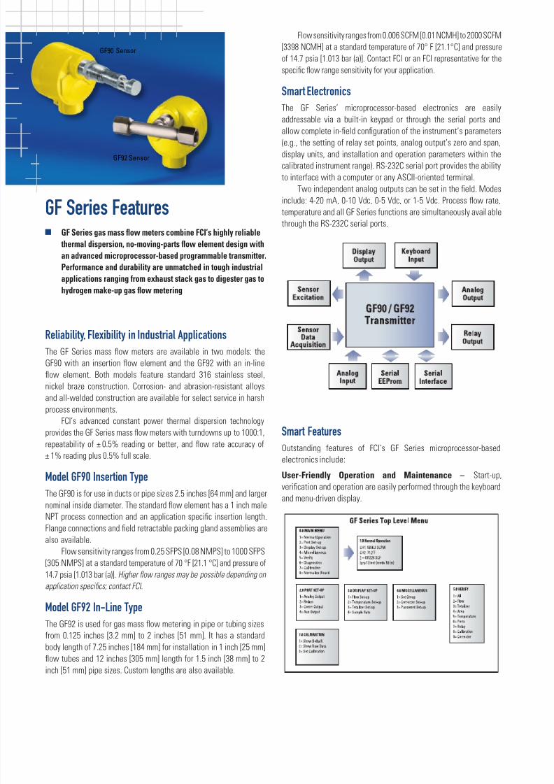
Smart Electronics
The GF Series’ microprocessor-based electronics are easily
addressable via a built-in keypad or through the serial ports and
allow complete in-field configuration of the instrument’s parameters(e.g., the setting of relay set points, analog output’s zero and span,
display units, and installation and operation parameters within the
calibrated instrument range). RS-232C serial port provides the ability
to interface with a computer or any ASCII-oriented terminal.
Two independent analog outputs can be set in the field. Modes
include: 4-20 mA, 0-10 Vdc, 0-5 Vdc, or 1-5 Vdc. Process flow rate,
temperature and all GF Series functions are simultaneously available
through the RS-232C serial ports.
Smart Features
Outstanding features of FCI’s GF Series microprocessor-based
electronics include:
User-Friendly Operation and Maintenance – Start-up,
verification and operation are easily performed through the keyboard
and menu-driven display.
GF Series Featuresg GF Series gas mass flow meters combine FCI’s highly reliable
thermal dispersion, no-moving-parts flow element design with
an advanced microprocessor-based programmable transmitter.
Performance and durability are unmatched in tough industrialapplications ranging from exhaust stack gas to digester gas to
hydrogen make-up gas flow metering
GF90 Sensor
GF92 Sensor
8/12/2019 GF Brochure RevL VeriCal RevC
http://slidepdf.com/reader/full/gf-brochure-revl-verical-revc 3/6
Indicator Display – Four lines by twenty character
liquid crystal display indicates flow rate, total flow,
temperature, relay status, current calibration
mode and sample rate. Flow rate, total flow and
temperature can be independently set to Imperial
or Metric (SI) units.
In-Field Programming – The built-in keypad
permits easy touch, in-field programming to change
zero, span, switch points, units of measurement,two totalizer modes, instrument verification, trouble
shooting and other critical instrument functions.
Built-in testing and diagnostics. Built-in testing and
diagnostic capabilities ensure accurate and reliable
performance. Diagnostics include out of range
detection and forced relay status.
Built-In Testing and Diagnostics – Built-in testing and diagnostic
capabilities ensure accurate and reliable performance. Diagnostics
include out of range detection and forced relay status.
Non-Volatile Memory – Non-volatile memory prevents the loss of
valuable application data and totalized flow due to loss of power.Security – Pass-code protection offers security against both
unauthorized access and equipment tampering.
Multiple Calibration Groups – Up to three calibration groups
can be stored in a single GF Series transmitter. Each group can be
independently configured for a specific calibration range, media,
switch point settings, etc. For example, a hydrogen line that requires
periodic purging with nitrogen gas can be measured with a single GF
Series mass flow meter. The complete calibration data for each gas
can be stored in one of three available groups. Each calibration group
can be manually or automatically selected to provide an accurate
indication of a specific process gas.
The three calibration groups can also be utilized to enhance or
preserve accuracy over wide flow turndowns. Accurate flows with
turndown ratios of 1000:1 are possible through group linkage. In
addition, automatic switching between groups can also be controlled
by process temperature variations.
Auxiliary Input Terminal – An auxiliary input terminal is available
for connection to an external signal source. This terminal provides a
method for remotely switching between calibration groups.
Enclosures – The local flow element enclosures are NEMA 4X
and Ex-rated available in either aluminum or 316L stainless steel.
Optionally, the sensor element can be supplied with no enclosure,
with only wire or cable pigtail termination. The standard transmitter/
electronics enclosures are rugged, NEMA 4X/IP66 rated fiberglass type
available with either two (2) 1 inch NPT(F) conduit ports or three (3) 21mm openings for user installation of M20 or M25 conduit connections
or cable glands. An aluminum NEMA 4X and Ex-rated enclosure with
three (3) 1 inch NPT(F) conduit ports is optionally available.
Agency Approvals – System agency approvals for hazardous
installations include FM, CSA, ATEX, IECEx and GOST/RTN.
Additional approvals and certifications include CPA, Canadian CRN
and PED, and CE mark.
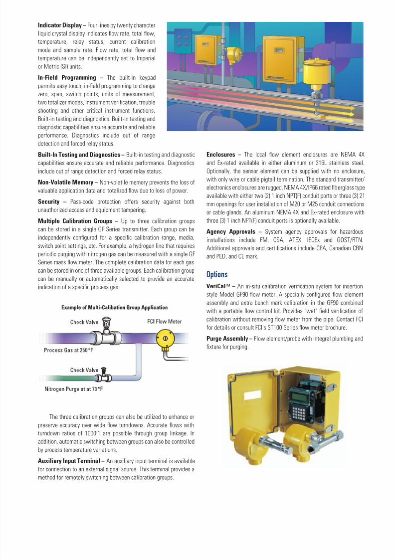
Options
VeriCal™ – An in-situ calibration verification system for insertion
style Model GF90 flow meter. A specially configured flow element
assembly and extra bench mark calibration in the GF90 combined
with a portable flow control kit. Provides "wet" field verification of
calibration without removing flow meter from the pipe. Contact FCI
for details or consult FCI's ST100 Series flow meter brochure.
Purge Assembly – Flow element/probe with integral plumbing and
fixture for purging.
8/12/2019 GF Brochure RevL VeriCal RevC
http://slidepdf.com/reader/full/gf-brochure-revl-verical-revc 4/6
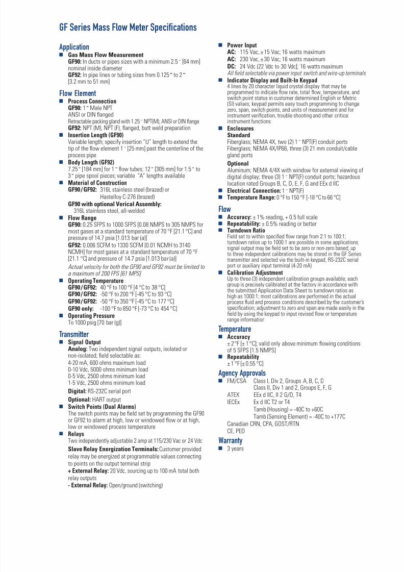
GF Series Mass Flow Meter Specifications
Applicationg Gas Mass Flow Measurement
GF90: In ducts or pipes sizes with a minimum 2.5 ʺ [64 mm]nominal inside diameterGF92: In pipe lines or tubing sizes from 0.125 ʺ to 2 ʺ
[3.2 mm to 51 mm]
Flow Elementg Process Connection
GF90: 1 ʺ Male NPTANSI or DIN flangedRetractable packing gland with 1.25 ̋ NPT(M), ANSI or DIN flangeGF92: NPT (M), NPT (F), flanged, butt weld preparation
g Insertion Length (GF90)Variable length; specify insertion “U” length to extend thetip of the flow element 1 ʺ [25 mm] past the centerline of theprocess pipe
g Body Length (GF92)7.25 ʺ [184 mm] for 1 ʺ flow tubes; 12 ʺ [305 mm] for 1.5 ʺ to3 ʺ pipe spool pieces; variable "A" lengths available
g Material of ConstructionGF90 / GF92: 316L stainless steel (brazed) or
Hastelloy C-276 (brazed)GF90 with optional Verical Assembly:
316L stainless steel, all-weldedg Flow Range
GF90: 0.25 SFPS to 1000 SFPS [0.08 NMPS to 305 NMPS formost gases at a standard temperature of 70 °F [21.1 °C] andpressure of 14.7 psia [1.013 bar (a)]GF92: 0.006 SCFM to 1330 SCFM [0.01 NCMH to 3140NCMH] for most gases at a standard temperature of 70 °F[21.1 °C] and pressure of 14.7 psia [1.013 bar (a)]
Actual velocity for both the GF90 and GF92 must be limited toa maximum of 200 FPS [61 MPS]
g Operating Temperature GF90 / GF92: 40 °F to 100 °F [4 °C to 38 °C]GF90 / GF92:
-50 °F to 200 °F [-45 °C to 93 °C]GF90 / GF92: -50 °F to 350 °F [-45 °C to 177 °C]GF90 only: -100 °F to 850 °F [-73 °C to 454 °C]
g Operating Pressure To 1000 psig [70 bar (g)]
Transmitterg Signal Output
Analog: Two independent signal outputs, isolated ornon-isolated; field selectable as:4-20 mA, 600 ohms maximum load0-10 Vdc, 5000 ohms minimum load0-5 Vdc, 2500 ohms minimum load1-5 Vdc, 2500 ohms minimum load
Digital: RS-232C serial port
Optional: HART outputg Switch Points (Dual Alarms)
The switch points may be field set by programming the GF90or GF92 to alarm at high, low or windowed flow or at high,low or windowed process temperature
g RelaysTwo independently adjustable 2 amp at 115/230 Vac or 24 Vdc
Slave Relay Energization Terminals: Customer providedrelay may be energized at programmable values connectingto points on the output terminal strip+ External Relay: 20 Vdc, sourcing up to 100 mA total bothrelay outputs- External Relay: Open/ground (switching)
g Power InputAC: 115 Vac, ± 15 Vac; 16 watts maximumAC: 230 Vac, ± 30 Vac; 16 watts maximumDC: 24 Vdc (22 Vdc to 30 Vdc]; 16 watts maximumAll field selectable via power input switch and wire-up terminals
g Indicator Display and Built-In Keypad4 lines by 20 character liquid crystal display that may beprogrammed to indicate flow rate, total flow, temperature, and
switch point status in customer determined English or Metric(SI) values; keypad permits easy touch programming to changezero, span, switch points, and units of measurement and forinstrument verification, trouble shooting and other criticalinstrument functions
g EnclosuresStandard Fiberglass; NEMA 4X, two (2) 1 ʺ NPT(F) conduit portsFiberglass; NEMA 4X/IP66, three (3) 21 mm conduit/cablegland ports
OptionalAluminum; NEMA 4/4X with window for external viewing ofdigital display; three (3) 1 ʺ NPT(F) conduit ports; hazardouslocation rated Groups B, C, D, E, F, G and EEx d IIC
g Electrical Connection: 1 ʺ NPT(F)
g Temperature Range: 0 °F to 150 °F [-18 °C to 66 °C]
Flowg Accuracy: ± 1% reading, + 0.5 full scaleg Repeatability: ± 0.5% reading or betterg Turndown Ratio
Field set to within specified flow range from 2:1 to 100:1;turndown ratios up to 1000:1 are possible in some applications;signal output may be field set to be zero or non-zero based; upto three independent calibrations may be stored in the GF Seriestransmitter and selected via the built-in keypad, RS-232C serialport or auxiliary input terminal (4-20 mA)
g Calibration AdjustmentUp to three (3) independent calibration groups available; eachgroup is precisely calibrated at the factory in accordance withthe submitted Application Data Sheet to turndown ratios as
high as 1000:1; most calibrations are performed in the actualprocess fluid and process conditions described by the customer’sspecification; adjustment to zero and span are made easily in thefield by using the keypad to input revised flow or temperaturerange information
Temperatureg Accuracy
± 2 °F [± 1 °C]; valid only above minimum flowing conditionsof 5 SFPS [1.5 NMPS]
g Repeatability± 1 °F [± 0.55 °C]
Agency Approvalsg FM/CSA Class I, Div 2, Groups A, B, C, D
Class II, Div 1 and 2, Groups E, F, G
ATEX EEx d IIC, II 2 G/D, T4 IECEx Ex d IIC T2 or T4 Tamb (Housing) = -40C to +60C Tamb (Sensing Element) = -40C to +177C Canadian CRN, CPA, GOST/RTN CE, PED
Warrantyg 3 years
8/12/2019 GF Brochure RevL VeriCal RevC
http://slidepdf.com/reader/full/gf-brochure-revl-verical-revc 5/6
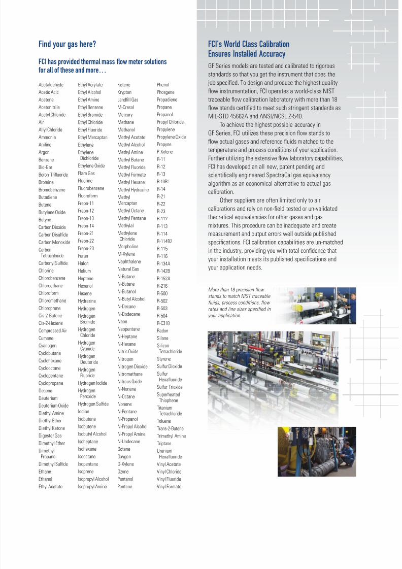
FCI’s World Class CalibrationEnsures Installed Accuracy
GF Series models are tested and calibrated to rigorous
standards so that you get the instrument that does the
job specified. To design and produce the highest quality
flow instrumentation, FCI operates a world-class NIST
traceable flow calibration laboratory with more than 18flow stands certified to meet such stringent standards as
MIL-STD 45662A and ANSI/NCSL Z-540.
To achieve the highest possible accuracy in
GF Series, FCI utilizes these precision flow stands to
flow actual gases and reference fluids matched to the
temperature and process conditions of your application.
Further utilizing the extensive flow laboratory capabilities,
FCI has developed an all new, patent pending and
scientifically engineered SpectraCal gas equivalency
algorithm as an economical alternative to actual gas
calibration.
Other suppliers are often limited only to air
calibrations and rely on non-field tested or un-validated
theoretical equivalencies for other gases and gas
mixtures. This procedure can be inadequate and create
measurement and output errors well outside published
specifications. FCI calibration capabilities are un-matched
in the industry, providing you with total confidence that
your installation meets its published specifications and
your application needs.
More than 18 precision flow
stands to match NIST traceablefluids, process conditions, flow
rates and line sizes specified in
your application.
Find your gas here?
FCI has provided thermal mass flow meter solutionsfor all of these and more…
Acetaldehyde
Acetic Acid
Acetone
Acetonitrile
Acetyl Chloride
Air
Allyl Chloride
Ammonia
Aniline
Argon
Benzene
Bio-Gas
Boron Trifluoride
Bromine
Bromobenzene
ButadieneButene
Butylene Oxide
Butyne
Carbon Dioxide
Carbon Disulfide
Carbon Monoxide
CarbonTetrachloride
Carbonyl Sulfide
Chlorine
Chlorobenzene
Chloroethane
ChloroformChloromethane
Chloroprene
Cis-2-Butene
Cis-2-Hexene
Compressed Air
Cumene
Cyanogen
Cyclobutane
Cyclohexane
Cyclooctane
Cyclopentane
Cyclopropane
Decene
Deuterium
Deuterium Oxide
Diethyl Amine
Diethyl Ether
Diethyl Ketone
Digester Gas
Dimethyl Ether
DimethylPropane
Dimethyl Sulfide
Ethane
Ethanol
Ethyl Acetate
Ethyl Acrylate
Ethyl Alcohol
Ethyl Amine
Ethyl Benzene
Ethyl Bromide
Ethyl Chloride
Ethyl Fluoride
Ethyl Mercaptan
Ethylene
EthyleneDichloride
Ethylene Oxide
Flare Gas
Fluorine
Fluorobenzene
FluoroformFreon-11
Freon-12
Freon-13
Freon-14
Freon-21
Freon-22
Freon-23
Furan
Halon
Helium
Heptene
Hexanol
HexeneHydrazine
Hydrogen
HydrogenBromide
HydrogenChloride
HydrogenCyanide
HydrogenDeuteride
HydrogenFluoride
Hydrogen Iodide
HydrogenPeroxide
Hydrogen Sulfide
Iodine
Isobutane
Isobutene
Isobutyl Alcohol
Isoheptane
Isohexane
Isooctane
Isopentane
Isoprene
Isopropyl Alcohol
Isopropyl Amine
Ketene
Krypton
Landfill Gas
M-Cresol
Mercury
Methane
Methanol
Methyl Acetate
Methyl Alcohol
Methyl Amine
Methyl Butane
Methyl Fluoride
Methyl Formate
Methyl Hexane
Methyl Hydrazine
MethylMercaptan
Methyl Octane
Methyl Pentane
Methylal
MethyleneChloride
Morpholine
M-Xylene
Naphthalene
Natural Gas
N-Butane
N-Butane
N-Butanol
N-Butyl Alcohol
N-Decane
N-Dodecane
Neon
Neopentane
N-Heptane
N-Hexane
Nitric Oxide
Nitrogen
Nitrogen Dioxide
Nitromethane
Nitrous Oxide
N-Nonane
N-Octane
Nonene
N-Pentane
N-Propanol
N-Propyl Alcohol
N-Propyl Amine
N-Undecane
Octene
Oxygen
O-Xylene
Ozone
Pentanol
Pentene
Phenol
Phosgene
PropadienePropane
Propanol
Propyl Chloride
Propylene
Propylene Oxide
Propyne
P-Xylene
R-11
R-12
R-13
R-13B1
R-14
R-21R-22
R-23
R-112
R-113
R-114
R-114B2
R-115
R-116
R-134A
R-142B
R-152A
R-216
R-500R-502
R-503
R-504
R-C318
Radon
Silane
SiliconTetrachloride
Styrene
Sulfur Dioxide
SulfurHexafluoride
Sulfur Trioxide
SuperheatedThiophene
TitaniumTetrachloride
Toluene
Trans-2-Butene
Trimethyl Amine
Triptane
UraniumHexafluoride
Vinyl Acetate
Vinyl Chloride
Vinyl Fluoride
Vinyl Formate
8/12/2019 GF Brochure RevL VeriCal RevC
http://slidepdf.com/reader/full/gf-brochure-revl-verical-revc 6/6
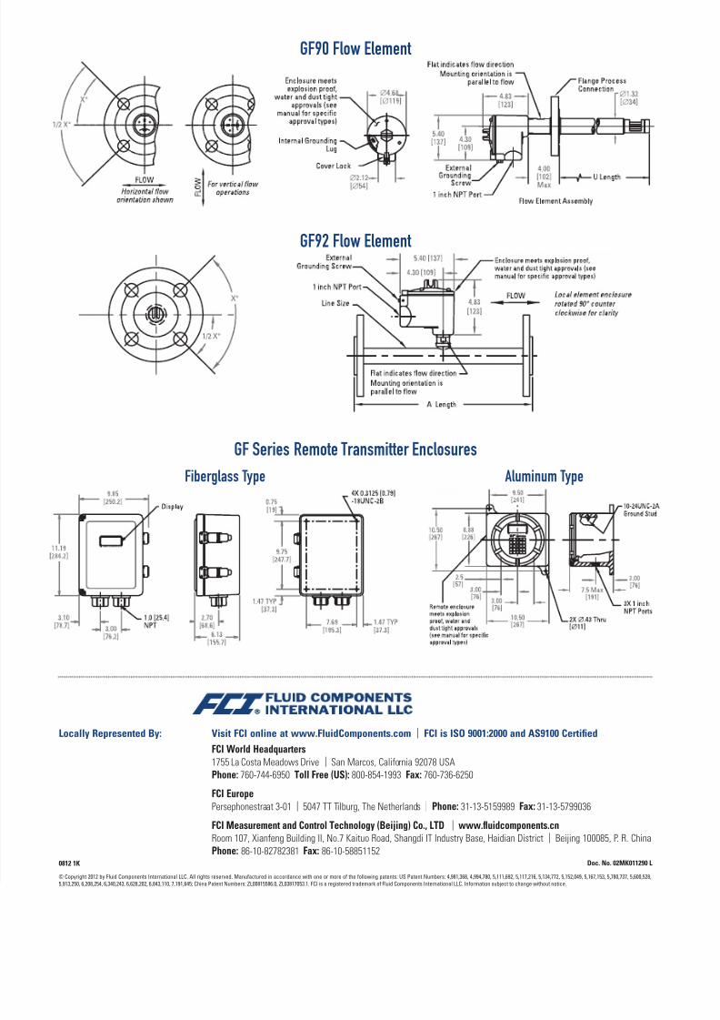
GF90 Flow Element
GF92 Flow Element
GF Series Remote Transmitter Enclosures
Fiberglass Type Aluminum Type
Visit FCI online at www.FluidComponents.com | FCI is ISO 9001:2000 and AS9100 Certified
FCI World Headquarters1755 La Costa Meadows Drive | San Marcos, California 92078 USAPhone: 760-744-6950 Toll Free (US): 800-854-1993 Fax: 760-736-6250
FCI EuropePersephonestraat 3-01 | 5047 TT Tilburg, The Netherlands | Phone: 31-13-5159989 Fax: 31-13-5799036
FCI Measurement and Control Technology (Beijing) Co., LTD | www.fluidcomponents.cnRoom 107, Xianfeng Building II, No.7 Kaituo Road, Shangdi IT Industry Base, Haidian District | Beijing 100085, P. R. ChinaPhone: 86-10-82782381 Fax: 86-10-58851152
Locally Represented By:
© Copyright 2012 by Fluid Components International LLC. All rights reserved. Manufactured in accordance with one or more of the following patents: US Patent Numbers: 4,981,368, 4,994,780, 5,111,692, 5,117,216, 5,134,772, 5,152,049, 5,167,153, 5,780,737, 5,600,528,
5,913,250, 6,208,254, 6,340,243, 6,628,202, 6,843,110, 7,191,645; China Patent Numbers: ZL00815586.0, ZL03817053.1. FCI is a registered trademark of Fluid Components International LLC. Information subject to change without notice.
Doc. No. 02MK011290 L0812 1K