Embed Size (px)
Citation preview
1
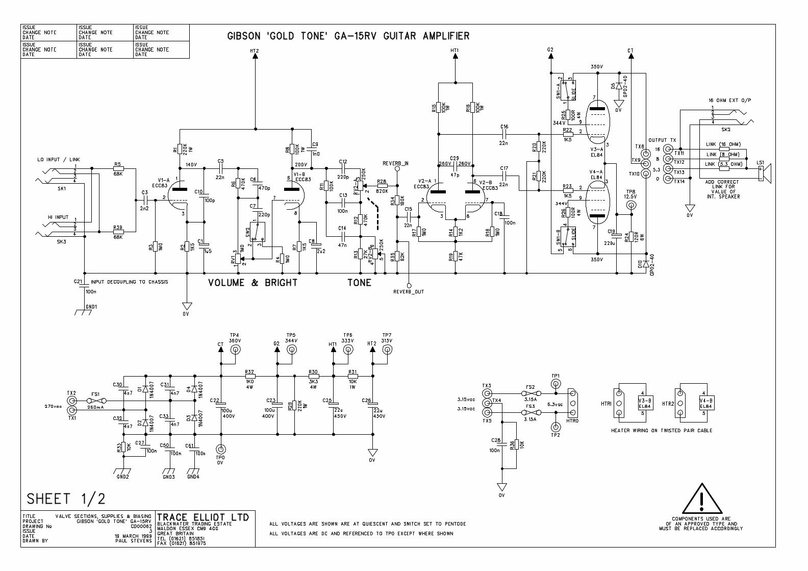
GIBSON ‘GOLD TONE’ GA-15RV CIRCUIT DISCRIPTION
Please refer to circuit diagram for DC voltages and other information
INPUT SECTION AND PREAMP
SK1 and SK3 are the LO and HI sensitivity inputs respectively. When the LO socket is usedR5, R39 and R3 act as a potential divider to reduce the input level to the preamp.
C3 has two purposes, firstly to block any DC from the input that may unintentionally bepresent, this would otherwise change the bias point of the first valve stage, secondly the valueof the capacitor has been chosen so that there is a slight roll off of lower frequencies, thisprevents the sound from getting too muddy.
V1a is the first gain stage and is configured as a cathode bias, common cathode, voltageamplifier with bypassed cathode resistor for increased gain.
R6 and C6 give a slight presence lift and the frequency of the Bright effect is set by C7, which,when switched in, is across pins 2 and 3 of RV1 (Volume). Obviously connected like this theamount of brightness added will decrease as RV1 is turned up.
V1b is the second gain stage configured similar to before, C9 is added across the anoderesistor R8 to smooth out the top end.
The Tone network is passive and controlled by RV2. This is a dual ganged potentiometer, onepart of which effectively controls the mids (RV2B) while the other part inversely controls thetreble (RV2A).
R28, R34 and R35 act as a potential divider to lower the signal sent to the reverb circuitry.
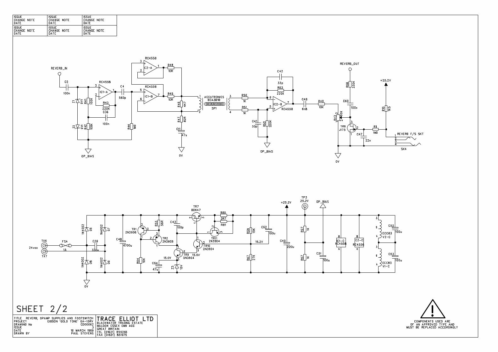
REVERB SECTION
The signal from the preamp is fed into IC1A which is configured as a boot strapped voltagefollower. Z1 and Z2 have been added to prevent any nasty spikes from damaging the opamp,this should in practise never happen.
C4 and R44 roll off a lot of the lower frequencies before the signal gets sent to IC1B andIC2A. These opamps are configured for current gain, the actual gain being dependant on theimpedance/frequency curve of the reverb tray. Because of this it is crucial to the correctoperation of the reverb that the right reverb tray is used. This should be an Accutronics8CA3B1B.
The output of the reverb tray goes into IC2B. This is configured as a differential amplifier as away of reducing any hum that may be picked up on the sensitive reverb return leads.
2
RV3 controls the level of the reverb. Across pins 1 and 2 is TR6, a J175 FET. When SK4 isshorted out, by a footswitch, TR6 is also effectively shorted which results in the reverb beingturned off.
The reverb signal is then mixed with the dry signal, via R58, before going into the phasesplitter.
POWER STAGE
The phase splitter (V2A and V2B) is a differential input splitter which produces the two antiphase signals necessary to drive the push pull output stage.
V3 and V4 are the two EL84 output valves connected as a push pull, cathode biased class Apower amplifier.
The quiescent current is set by R24, which is bypassed by C19 for extra gain.
SW1A and SW1B is an electrically robust slider switch used to switch the power valves fromPentode to Triode operation. For Pentode operation the screen grid (grid 2, pin 9) isconnected, via the screen grid current limiting resistors R25 and R26, to the highly smoothedscreen grid supply, G2 - positive pin of C23. For Triode operation the screen grid of eachvalve is connected to the corresponding anode.Triode operation basically reduces the power output to a bit less than half and also reducesthe high frequencies in the overall sound.
D5 and D10 have been added to give protection to the output transformer should a fault arise.
OUTPUT TRANSFORMER AND SPEAKER CONNECTIONS
The output transformer has secondary taps for 16Ω, 8Ω and 5.3 Ω. The 16Ω tap is used todrive the External Speaker Output, SK2. When a jack plug is inserted into SK2 the internalspeaker is disconnected.
The three LINK positions are provided on the PCB so that different impedance internalspeakers can be used in production. Depending on whether the internal speaker is 16Ω, 8Ωor 5.3 Ω the correct LINK should be fitted. This has been done purely so that differentimpedance speakers can be used if there are any problems with supply.
POWER SUPPLIES
All three supplies, HT, ac heater, and DC supplies have secondary fusing on the PCB. This isto protect the mains transformer and for approvals.
The HT supply is a very simple bridge rectifier diode network, with 4n7 1KV capacitorsacross each diode for EMC reasons, which is then smoothed by C22, to supply the centre tapof the output transformer. This is then further smoothed by R32/C23, R30/C25 and R31/C26to supply the screen grids, phase splitter and preamp respectively.R29 is added to discharge the high voltage capacitors when then unit is turned off.
3
The ac heater supply is simply connected via a twisted pair connecting lead to V3 and V4after first going through the secondary fuses
The 25.2V DC supply is highly regulated supply using a BD647 (TR7) as the main regulatingdevice. (Please ensure that the small clip on heat sink is attached to TR7)TR1 and TR2 provide a constant current source for Z3 the 15 volt zener.
The output voltage is set by the ratio of R59 and R67 which provide the feedback to TR7 viaTR9 and TR10 to stabilise the whole circuit, and TR11 with R80 and R81 form a currentlimiter. This allows the supply voltage to ramp up at switch on when the heater filaments of thepreamp valves draw considerably more current while cold.
R27 and R57 halve the supply voltage to provide the opamp bias voltage, and as shown onthe circuit diagram the DC supply is routed first through the two filaments in V2 in series andthen through the two filaments in V1. This will result in each filament having the nominal 6.3volts across them.
Paul Stevens30 June 1999
GIBSON ‘GOLDTONE’ GA-15RV
The GA-15RV is part of the Gibson ‘GoldTone’ valve guitar amplifier range. It is a nononsense, compact, purists valve guitar amplifier and has the minimum controls necessary toproduce a good range of sounds, from clean to overdriven, into its single speaker.
The circuit topology has been based on traditional guitar amplifier designs, with new ideasincorporated where beneficial.
The main preamp and power stage sections are 100% valve. The valves used are twoECC83/12AX7’s and two EL84/6BQ5’s run in Cathode Biased Class A.
CONTROLS
INPUTS - HI & LO/LINK
Two jack sockets are provided for connection to your instrument.
The HI input is a high impedance, high sensitivity input. This can be used with both passiveand active guitars and, depending on the level of output from the guitar and the VOLUMEsetting, allows the amplifier to be driven hard into overdrive, if desired.
The LO/LINK socket can be used in two ways. Firstly as a lower impedance, low sensitivityinput, for use with high output guitars when the user wishes to keep the overdrive undercontrol. Alternatively this socket can be used as a LINK to chain together two or more‘GoldTone’s, simply plug your guitar into the HI socket, take an output from the LO/LINKsocket and plug this into the input of the next amplifier in the chain.
BRIGHT
The BRIGHT switch adds more high frequencies when selected. It works in the traditional way,therefore it has more effect at lower VOLUME settings.
VOLUME
This sets the overall volume level of the amplifier as well as having a huge effect on the toneand the amount of overdrive. From low to about halfway, depending on the output level of theguitar and which input socket is used, the sound should remain reasonably clean. Increasingthe control further will progressively increase the level of overdrive in the sound, obviouslybeing a valve amp it will respond to the player’s dynamics and use of the instruments volume.
TONE
Unlike other single tone controls on other amplifiers, which act merely as a treble roll off, thiscontrol works in a different way. It is a dual gang potentiometer which controls two functionssimultaneously. In the fully anti-clockwise position the midrange is dominant in the sound,turning the control clockwise decreases the mids while at the same time increasing the higherfrequencies.
REVERB
This single control is for adjusting the amount of reverb effect in the sound. The effect isproduced by a three spring reverb tray inside the cabinet.
FOOTSWITCH SOCKET
This socket is for connecting to a latching footswitch and allows the user to turn the reverbeffect on or off during a performance.
EXTERNAL SPEAKER OUTPUT
This is provided so that the user can connect the GA-15RV to an external 16Ω speakercabinet, such as a 4x12, for a different sound. This is useful for both live and studio use andcan radically change the sound of the amplifier. Try it at high volume into a 4x12 and you willnot believe you are playing a 15 watt amp!
When a jack is inserted into this socket the internal speaker is disconnected. Always ensurethat the amplifier is correctly loaded when in use.
PENTODE/TRIODE SWITCH
This allows the user to set the power stage to either PENTODE or TRIODE operation.
PENTODE position is the full power mode and has generally a more powerful sound with aspread of both even and odd harmonics, when pushed into distortion.
TRIODE mode produces around half as much power. It therefore has less headroom andproduces power amp distortion earlier. It also has less high frequency content, therefore it isnot as bright as pentode mode, and produces mainly even order harmonics.
The choice as to which mode to use will depend on several factors including playing situation,instrument used and, most importantly, personal taste.
POWER SWITCH (OFF/STANDBY/ON)
As the name implies, this switches the amplifier from OFF to STANDBY mode, where only thevalve heaters are on, to ON for actual use. This should be used correctly every time the unit isused to prevent problems with valves and to increase their life.
Before mains is applied to the unit, check that it is the correct voltage and make sure thePOWER switch is in the OFF position. Connect power lead to mains outlet then switch toSTANDBY and wait about a minute before switching to ON. This will ensure that the valveshave time to warm up before large voltages are applied to the plates. During short breaks theamplifier can be switched to standby and will therefore be ready to play when next needed.
After switching off it is recommended, as with all valve amplifiers, that it does not receive anysudden physical shocks while the valves are still hot, i.e. through moving the unit. If possible tryto give the amplifier a few minutes to cool down before transporting it.
IEC SOCKET/MAINS FUSE
The IEC socket is for connection to universally used IEC mains leads to connect toappropriate domestic mains supply.
In the event of having to replace the mains fuse always use the same rating and type asmarked on the unit’s rear panel. Using one of higher rating will invalidate the guarantee.
If after replacement the mains fuse should blow a second time, immediately refer the unit to aTRACE ELLIOT approved service engineer for checking.
ORIENTATION OF VALVES
Looking at the GA-15RV from the rear with the rear paneI removed you will see four valves,the two on the left (V1 and V2) should be ECC83/12AX7’s and the two on the right (V3 andV4) should be EL84/6BQ5’s. For improved performance and reliability the EL84/6BQ5’sshould be a matched pair.
If the need should arise to replace any of the valves we recommend the following types:-
V1 and V2 Sovtek 12AX7WB or 12AX7WAV3 and V4 Ruby Tubes Tesla EL84
TECHNICAL SPECIFICATIONS
INPUT IMPEDANCE HI - 1MΩLO/LINK - 136KΩ
TONE CONTROL SINGLE DUAL FUNCTION PASSIVE CONTROL
REVERB 3 SPRING TRAY
CIRCUIT TOPOLOGY PREAMP AND POWER STAGE 100% VALVEREVERB SECTION DRIVEN BY INTEGRATED CIRCUITS
SPEAKER SINGLE 12” CELESTION
POWER RATING ~ 15W PENTODE~ 6W TRIODE
1
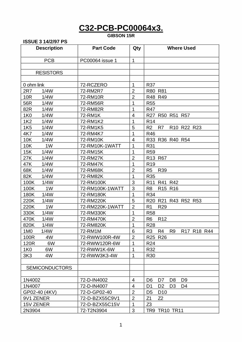
C32-PCB-PC00064x3.GIBSON 15R
ISSUE 3 14/2/97 PSDescription Part Code Qty Where Used
PCB PC00064 issue 1 1
RESISTORS
0 ohm link 72-RCZERO 1 R372R7 1/4W 72-RM2R7 2 R80 R8110R 1/4W 72-RM10R 2 R48 R4956R 1/4W 72-RM56R 1 R5582R 1/4W 72-RM82R 1 R471K0 1/4W 72-RM1K 4 R27 R50 R51 R571K2 1/4W 72-RM1K2 1 R141K5 1/4W 72-RM1K5 5 R2 R7 R10 R22 R234K7 1/4W 72-RM4K7 1 R4610K 1/4W 72-RM10K 4 R33 R36 R40 R5410K 1W 72-RM10K-1WATT 1 R3115K 1/4W 72-RM15K 1 R5927K 1/4W 72-RM27K 2 R13 R6747K 1/4W 72-RM47K 1 R1968K 1/4W 72-RM68K 2 R5 R3982K 1/4W 72-RM82K 1 R35100K 1/4W 72-RM100K 3 R11 R41 R42100K 1W 72-RM100K-1WATT 3 R8 R15 R16180K 1/4W 72-RM180K 1 R34220K 1/4W 72-RM220K 5 R20 R21 R43 R52 R53220K 1W 72-RM220K-1WATT 2 R1 R29330K 1/4W 72-RM330K 1 R58470K 1/4W 72-RM470K 2 R6 R12820K 1/4W 72-RM820K 1 R281M0 1/4W 72-RM1M 6 R3 R4 R9 R17 R18 R44100R 4W 72-RWW100R-4W 2 R25 R26120R 6W 72-RWW120R-6W 1 R241K0 6W 72-RWW1K-6W 1 R323K3 4W 72-RWW3K3-4W 1 R30
SEMICONDUCTORS
1N4002 72-D-IN4002 4 D6 D7 D8 D91N4007 72-D-IN4007 4 D1 D2 D3 D4GP02-40 (4KV) 72-D-GP02-40 2 D5 D109V1 ZENER 72-D-BZX55C9V1 2 Z1 Z215V ZENER 72-D-BZX55C15V 1 Z32N3904 72-T2N3904 3 TR9 TR10 TR11
2
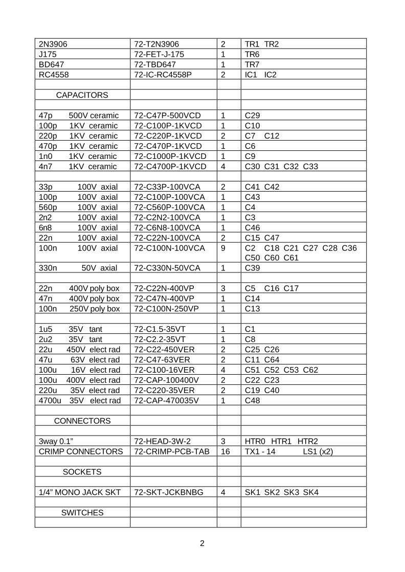
2N3906 72-T2N3906 2 TR1 TR2J175 72-FET-J-175 1 TR6BD647 72-TBD647 1 TR7RC4558 72-IC-RC4558P 2 IC1 IC2
CAPACITORS
47p 500V ceramic 72-C47P-500VCD 1 C29100p 1KV ceramic 72-C100P-1KVCD 1 C10220p 1KV ceramic 72-C220P-1KVCD 2 C7 C12470p 1KV ceramic 72-C470P-1KVCD 1 C61n0 1KV ceramic 72-C1000P-1KVCD 1 C94n7 1KV ceramic 72-C4700P-1KVCD 4 C30 C31 C32 C33
33p 100V axial 72-C33P-100VCA 2 C41 C42100p 100V axial 72-C100P-100VCA 1 C43560p 100V axial 72-C560P-100VCA 1 C42n2 100V axial 72-C2N2-100VCA 1 C36n8 100V axial 72-C6N8-100VCA 1 C4622n 100V axial 72-C22N-100VCA 2 C15 C47100n 100V axial 72-C100N-100VCA 9 C2 C18 C21 C27 C28 C36
C50 C60 C61330n 50V axial 72-C330N-50VCA 1 C39
22n 400V poly box 72-C22N-400VP 3 C5 C16 C1747n 400V poly box 72-C47N-400VP 1 C14100n 250V poly box 72-C100N-250VP 1 C13
1u5 35V tant 72-C1.5-35VT 1 C12u2 35V tant 72-C2.2-35VT 1 C822u 450V elect rad 72-C22-450VER 2 C25 C2647u 63V elect rad 72-C47-63VER 2 C11 C64100u 16V elect rad 72-C100-16VER 4 C51 C52 C53 C62100u 400V elect rad 72-CAP-100400V 2 C22 C23220u 35V elect rad 72-C220-35VER 2 C19 C404700u 35V elect rad 72-CAP-470035V 1 C48
CONNECTORS
3way 0.1” 72-HEAD-3W-2 3 HTR0 HTR1 HTR2CRIMP CONNECTORS 72-CRIMP-PCB-TAB 16 TX1 - 14 LS1 (x2)
SOCKETS
1/4” MONO JACK SKT 72-SKT-JCKBNBG 4 SK1 SK2 SK3 SK4
SWITCHES
3
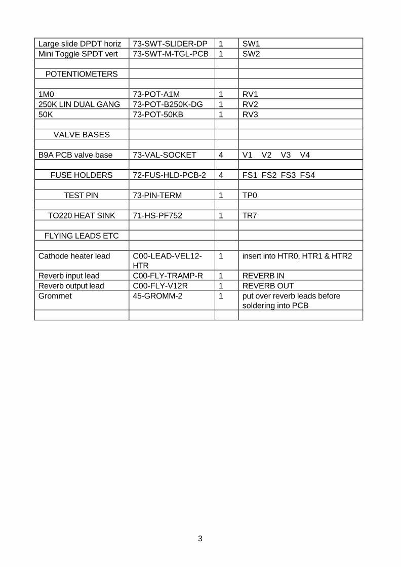
Large slide DPDT horiz 73-SWT-SLIDER-DP 1 SW1Mini Toggle SPDT vert 73-SWT-M-TGL-PCB 1 SW2
POTENTIOMETERS
1M0 73-POT-A1M 1 RV1250K LIN DUAL GANG 73-POT-B250K-DG 1 RV250K 73-POT-50KB 1 RV3
VALVE BASES
B9A PCB valve base 73-VAL-SOCKET 4 V1 V2 V3 V4
FUSE HOLDERS 72-FUS-HLD-PCB-2 4 FS1 FS2 FS3 FS4
TEST PIN 73-PIN-TERM 1 TP0
TO220 HEAT SINK 71-HS-PF752 1 TR7
FLYING LEADS ETC
Cathode heater lead C00-LEAD-VEL12-HTR
1 insert into HTR0, HTR1 & HTR2
Reverb input lead C00-FLY-TRAMP-R 1 REVERB INReverb output lead C00-FLY-V12R 1 REVERB OUTGrommet 45-GROMM-2 1 put over reverb leads before
soldering into PCB