Embed Size (px)
Citation preview
GLOSSARY
Following are acronyms which appear throughout this publication.
HDG Hot Dipped GalvanizedFGL Fiberglass304SS 304 Grade Stainless Steel316SS 316 Grade Stainless SteelEG Electro GalvanizedGIP Galvanized Iron PipeBIP Black Iron PipeS&H Split & HingedFRE Fiberglass Reinforced EpoxyID Inside DiameterIPS International Pipe StandardXHWI/O
Extra Heavy WallInner Outer Multiple Duct
www.OSBURNS.com • TOLL-FREE 1-800-523-8917 • TEL (740) 385-6869 • FAX (740) 385-8016
INDEX
I. General Information 1
II. Precautions 1
III. Conduit Support Systems for Bridges 1
IV. Locating Supports 2
V. Installing Supports 2
VI. Bracing 4
VII. Expansion Joint Installation 6
VIII. Installation of Conduits General 6
IX. Cementing Procedure FRE Conduit and Fittings 8
X. Summary 8
XI. Product Specifications PVC, Fiberglass, Steel Conduits 9
XII. Multiple Conduit 14
XIII. Duct Supports 15 XIV. Anchors and Inserts 16
XV. Hardware - U Bolts, Supports, Clamps, J Hangers, Brackets 17
XVI. Workzone/Safety 25
EXPANSION CHART
Temperature Approximate Length of Change in inches
Change (deg F) (per 100 feet)
FGL Steel PVC
40 .48 .30 1.6
60 .72 .45 2.4
80 .96 .60 3.2
100 1.20 .76 4.1
120 1.44 .91 4.8
140 1.68 1.07 5.6
160 1.92 1.22 6.4
180 2.16 1.40 7.2
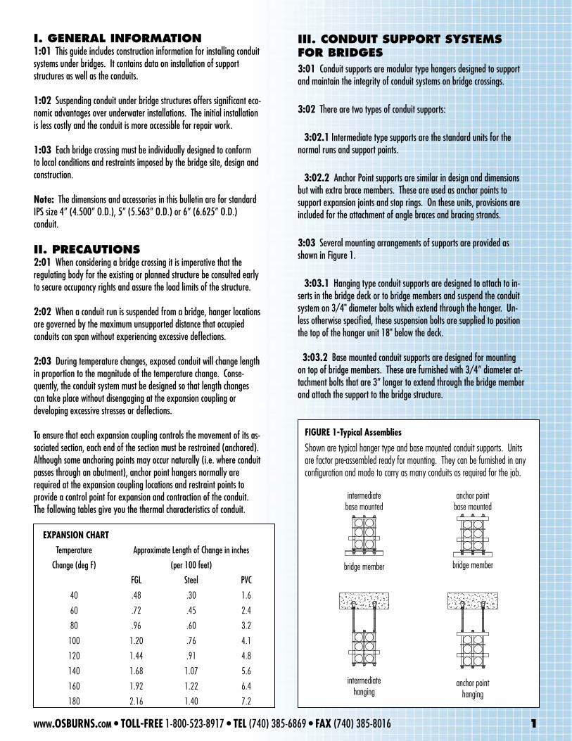
FIGURE 1-Typical Assemblies
Shown are typical hanger type and base mounted conduit supports. Units are factor pre-assembled ready for mounting. They can be furnished in any configuration and made to carry as many conduits as required for the job.
intermediatebase mounted
bridge member
anchor pointbase mounted
bridge member
www.OSBURNS.com • TOLL-FREE 1-800-523-8917 • TEL (740) 385-6869 • FAX (740) 385-8016 1
III. CONDuIt SuppORt SYStEmS fOR BRIDGES3:01 Conduit supports are modular type hangers designed to support and maintain the integrity of conduit systems on bridge crossings.
3:02 There are two types of conduit supports:
3:02.1 Intermediate type supports are the standard units for the normal runs and support points.
3:02.2 Anchor Point supports are similar in design and dimensions but with extra brace members. These are used as anchor points to support expansion joints and stop rings. On these units, provisions are included for the attachment of angle braces and bracing strands.
3:03 Several mounting arrangements of supports are provided as shown in Figure 1.
3:03.1 Hanging type conduit supports are designed to attach to in-serts in the bridge deck or to bridge members and suspend the conduit system on 3/4" diameter bolts which extend through the hanger. Un-less otherwise specified, these suspension bolts are supplied to position the top of the hanger unit 18" below the deck.
3:03.2 Base mounted conduit supports are designed for mounting on top of bridge members. These are furnished with 3/4” diameter at-tachment bolts that are 3” longer to extend through the bridge member and attach the support to the bridge structure.
I. GENERAL INfORmAtION1:01 This guide includes construction information for installing conduit systems under bridges. It contains data on installation of support structures as well as the conduits.
1:02 Suspending conduit under bridge structures offers significant eco-nomic advantages over underwater installations. The initial installation is less costly and the conduit is more accessible for repair work.
1:03 Each bridge crossing must be individually designed to conform to local conditions and restraints imposed by the bridge site, design and construction.
Note: The dimensions and accessories in this bulletin are for standard IPS size 4” (4.500” O.D.), 5” (5.563” O.D.) or 6” (6.625” O.D.) conduit.
II. pRECAutIONS2:01 When considering a bridge crossing it is imperative that the regulating body for the existing or planned structure be consulted early to secure occupancy rights and assure the load limits of the structure.
2:02 When a conduit run is suspended from a bridge, hanger locations are governed by the maximum unsupported distance that occupied conduits can span without experiencing excessive deflections.
2:03 During temperature changes, exposed conduit will change length in proportion to the magnitude of the temperature change. Conse-quently, the conduit system must be designed so that length changes can take place without disengaging at the expansion coupling or developing excessive stresses or deflections.
To ensure that each expansion coupling controls the movement of its as-sociated section, each end of the section must be restrained (anchored). Although some anchoring points may occur naturally (i.e. where conduit passes through an abutment), anchor point hangers normally are required at the expansion coupling locations and restraint points to provide a control point for expansion and contraction of the conduit. The following tables give you the thermal characteristics of conduit.
anchor pointhanging
intermediatehanging
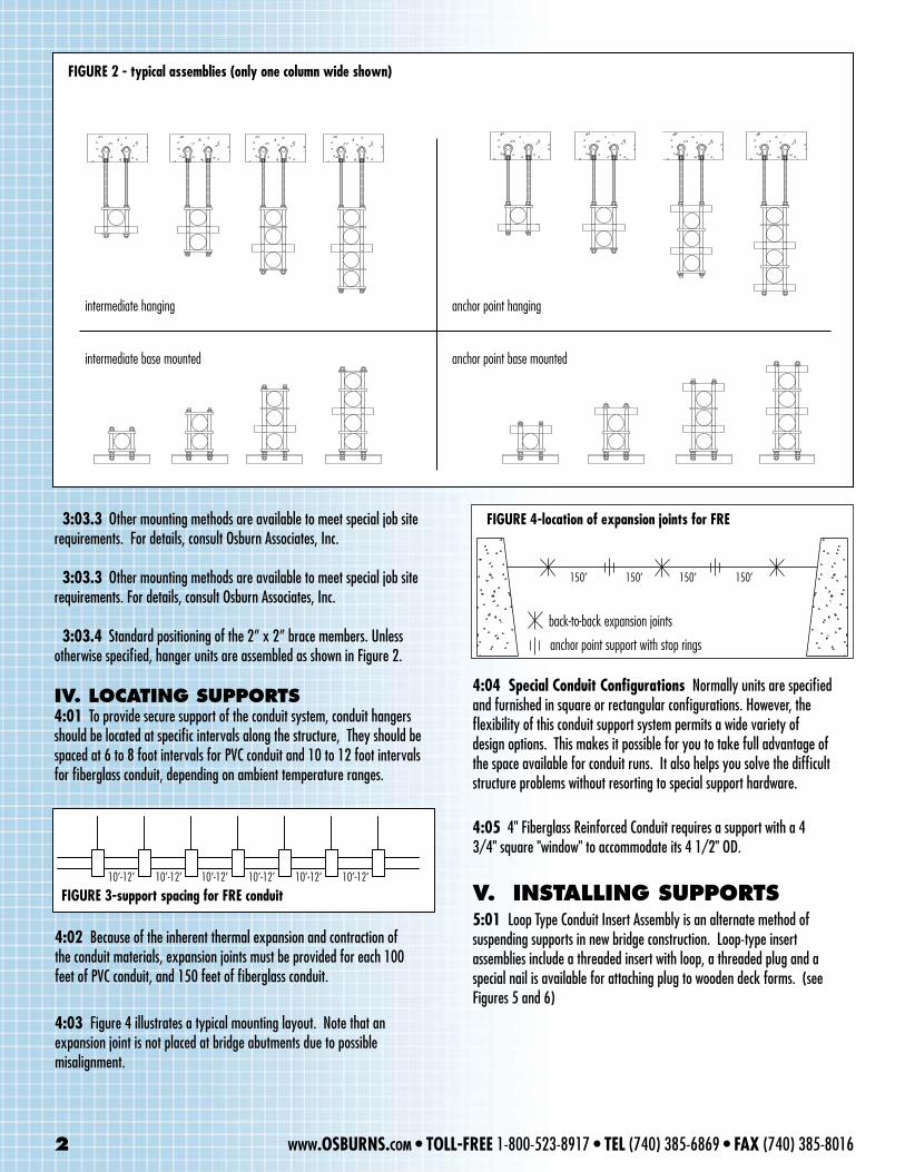
4:02 Because of the inherent thermal expansion and contraction of the conduit materials, expansion joints must be provided for each 100 feet of PVC conduit, and 150 feet of fiberglass conduit.
4:03 Figure 4 illustrates a typical mounting layout. Note that an expansion joint is not placed at bridge abutments due to possible misalignment.
FIGURE 2 - typical assemblies (only one column wide shown)
intermediate hanging
intermediate base mounted
anchor point hanging
anchor point base mounted
4:04 Special Conduit Configurations Normally units are specified and furnished in square or rectangular configurations. However, the flexibility of this conduit support system permits a wide variety of design options. This makes it possible for you to take full advantage of the space available for conduit runs. It also helps you solve the difficult structure problems without resorting to special support hardware.
4:05 4" Fiberglass Reinforced Conduit requires a support with a 4 3/4" square "window" to accommodate its 4 1/2" OD.
V. INStALLING SuppORtS5:01 Loop Type Conduit Insert Assembly is an alternate method of suspending supports in new bridge construction. Loop-type insert assemblies include a threaded insert with loop, a threaded plug and a special nail is available for attaching plug to wooden deck forms. (see Figures 5 and 6)
3:03.3 Other mounting methods are available to meet special job site requirements. For details, consult Osburn Associates, Inc.
3:03.3 Other mounting methods are available to meet special job site requirements. For details, consult Osburn Associates, Inc.
3:03.4 Standard positioning of the 2” x 2” brace members. Unless otherwise specified, hanger units are assembled as shown in Figure 2.
IV. LOCAtING SuppORtS4:01 To provide secure support of the conduit system, conduit hangers should be located at specific intervals along the structure, They should be spaced at 6 to 8 foot intervals for PVC conduit and 10 to 12 foot intervals for fiberglass conduit, depending on ambient temperature ranges.
FIGURE 3-support spacing for FRE conduit10’-12’ 10’-12’ 10’-12’ 10’-12’ 10’-12’ 10’-12’
conduitFIGURE 4-location of expansion joints for FRE
150’ 150’ 150’ 150’
back-to-back expansion joints
anchor point support with stop rings
2 www.OSBURNS.com • TOLL-FREE 1-800-523-8917 • TEL (740) 385-6869 • FAX (740) 385-8016
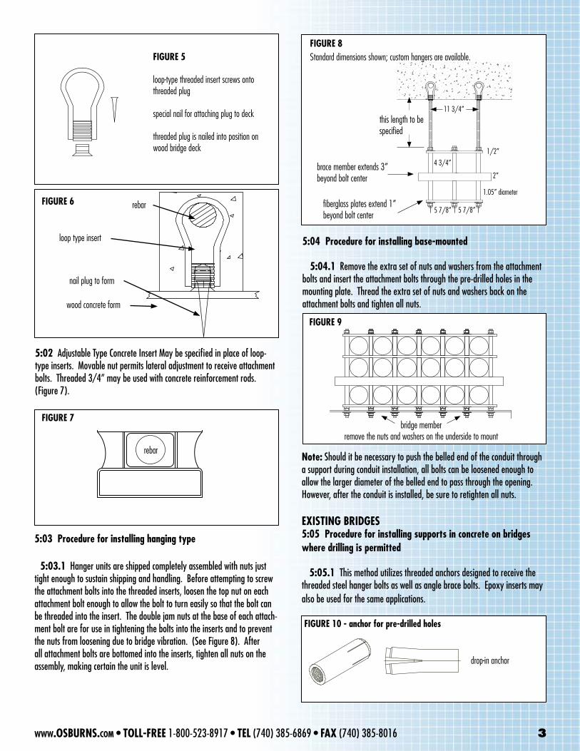
FIGURE 7
FIGURE 5
loop-type threaded insert screws onto threaded plug
special nail for attaching plug to deck
threaded plug is nailed into position on wood bridge deck
FIGURE 6
wood concrete form
nail plug to form
loop type insert
rebar
this length to bespecified
brace member extends 3” beyond bolt center
fiberglass plates extend 1” beyond bolt center
FIGURE 8Standard dimensions shown; custom hangers are available.
5 7/8”
4 3/4”
2”
1/2”
1.05” diameter
11 3/4”
bridge memberremove the nuts and washers on the underside to mount
FIGURE 9
5:02 Adjustable Type Concrete Insert May be specified in place of loop-type inserts. Movable nut permits lateral adjustment to receive attachment bolts. Threaded 3/4” may be used with concrete reinforcement rods. (Figure 7).
5:03 Procedure for installing hanging type
5:03.1 Hanger units are shipped completely assembled with nuts just tight enough to sustain shipping and handling. Before attempting to screw the attachment bolts into the threaded inserts, loosen the top nut on each attachment bolt enough to allow the bolt to turn easily so that the bolt can be threaded into the insert. The double jam nuts at the base of each attach-ment bolt are for use in tightening the bolts into the inserts and to prevent the nuts from loosening due to bridge vibration. (See Figure 8). After all attachment bolts are bottomed into the inserts, tighten all nuts on the assembly, making certain the unit is level.
5:04 Procedure for installing base-mounted
5:04.1 Remove the extra set of nuts and washers from the attachment bolts and insert the attachment bolts through the pre-drilled holes in the mounting plate. Thread the extra set of nuts and washers back on the attachment bolts and tighten all nuts.
Note: Should it be necessary to push the belled end of the conduit through a support during conduit installation, all bolts can be loosened enough to allow the larger diameter of the belled end to pass through the opening. However, after the conduit is installed, be sure to retighten all nuts.
EXISTING BRIDGES 5:05 Procedure for installing supports in concrete on bridges where drilling is permitted
5:05.1 This method utilizes threaded anchors designed to receive the threaded steel hanger bolts as well as angle brace bolts. Epoxy inserts may also be used for the same applications.
rebar
drop-in anchor
5 7/8”
FIGURE 10 - anchor for pre-drilled holes
www.OSBURNS.com • TOLL-FREE 1-800-523-8917 • TEL (740) 385-6869 • FAX (740) 385-8016 3
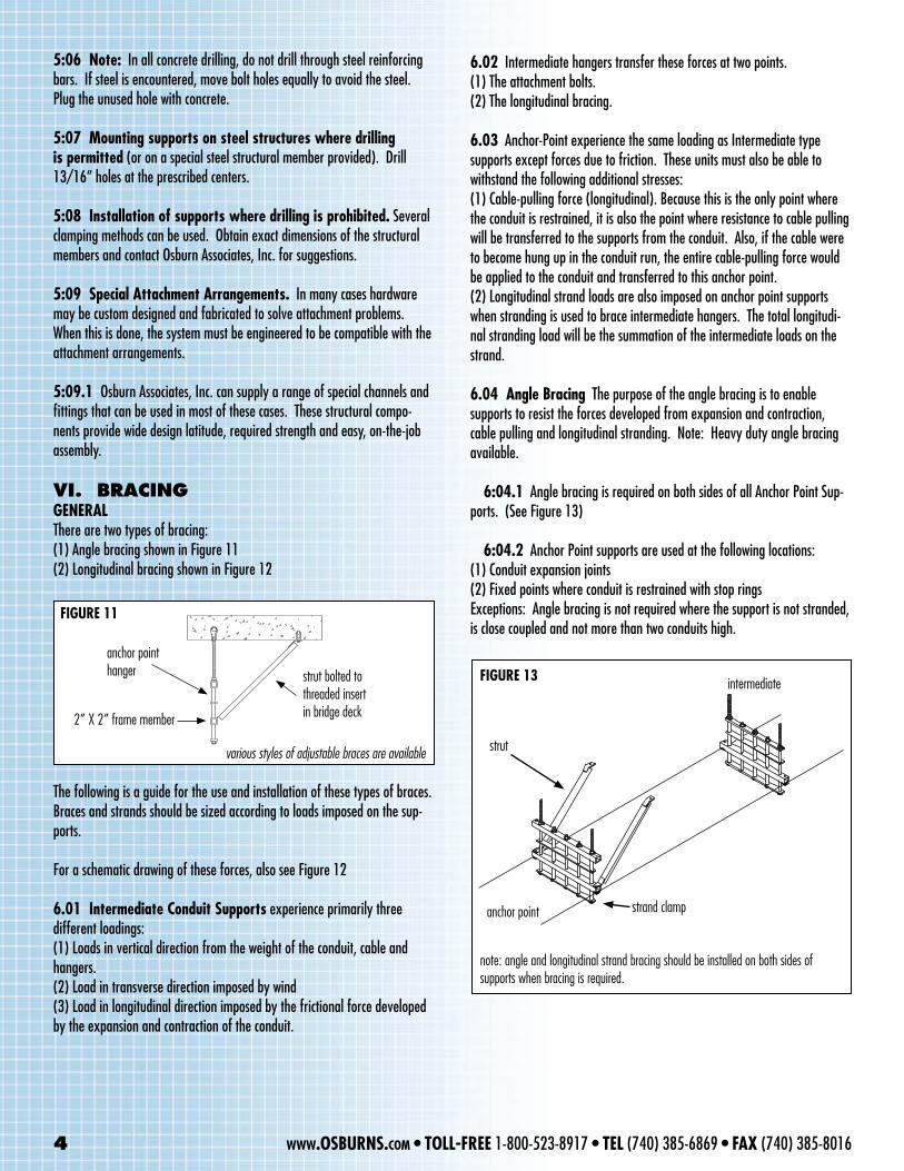
FIGURE 11
anchor point hanger strut bolted to
threaded insertin bridge deck2” X 2” frame member
various styles of adjustable braces are available
FIGURE 13
note: angle and longitudinal strand bracing should be installed on both sides of supports when bracing is required.
anchor point strand clamp
strut
intermediate
5:06 Note: In all concrete drilling, do not drill through steel reinforcing bars. If steel is encountered, move bolt holes equally to avoid the steel. Plug the unused hole with concrete.
5:07 Mounting supports on steel structures where drilling is permitted (or on a special steel structural member provided). Drill 13/16” holes at the prescribed centers.
5:08 Installation of supports where drilling is prohibited. Several clamping methods can be used. Obtain exact dimensions of the structural members and contact Osburn Associates, Inc. for suggestions.
5:09 Special Attachment Arrangements. In many cases hardware may be custom designed and fabricated to solve attachment problems. When this is done, the system must be engineered to be compatible with the attachment arrangements.
5:09.1 Osburn Associates, Inc. can supply a range of special channels and fittings that can be used in most of these cases. These structural compo-nents provide wide design latitude, required strength and easy, on-the-job assembly.
VI. BRACINGGENERALThere are two types of bracing:(1) Angle bracing shown in Figure 11(2) Longitudinal bracing shown in Figure 12
The following is a guide for the use and installation of these types of braces. Braces and strands should be sized according to loads imposed on the sup-ports.
For a schematic drawing of these forces, also see Figure 12
6.01 Intermediate Conduit Supports experience primarily three different loadings:(1) Loads in vertical direction from the weight of the conduit, cable and hangers.(2) Load in transverse direction imposed by wind(3) Load in longitudinal direction imposed by the frictional force developed by the expansion and contraction of the conduit.
6.02 Intermediate hangers transfer these forces at two points.(1) The attachment bolts.(2) The longitudinal bracing.
6.03 Anchor-Point experience the same loading as Intermediate type supports except forces due to friction. These units must also be able to withstand the following additional stresses:(1) Cable-pulling force (longitudinal). Because this is the only point where the conduit is restrained, it is also the point where resistance to cable pulling will be transferred to the supports from the conduit. Also, if the cable were to become hung up in the conduit run, the entire cable-pulling force would be applied to the conduit and transferred to this anchor point.(2) Longitudinal strand loads are also imposed on anchor point supports when stranding is used to brace intermediate hangers. The total longitudi-nal stranding load will be the summation of the intermediate loads on the strand.
6.04 Angle Bracing The purpose of the angle bracing is to enable supports to resist the forces developed from expansion and contraction, cable pulling and longitudinal stranding. Note: Heavy duty angle bracing available.
6:04.1 Angle bracing is required on both sides of all Anchor Point Sup-ports. (See Figure 13)
6:04.2 Anchor Point supports are used at the following locations:(1) Conduit expansion joints(2) Fixed points where conduit is restrained with stop ringsExceptions: Angle bracing is not required where the support is not stranded, is close coupled and not more than two conduits high.
4 www.OSBURNS.com • TOLL-FREE 1-800-523-8917 • TEL (740) 385-6869 • FAX (740) 385-8016
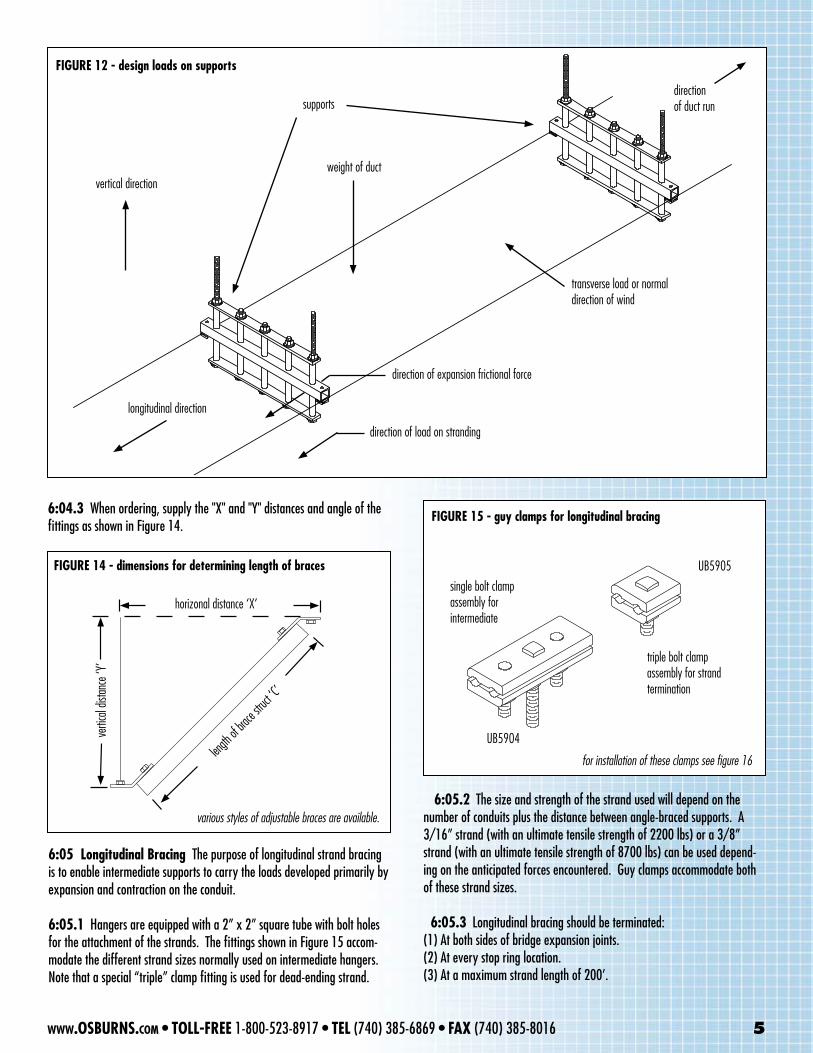
FIGURE 12 - design loads on supports
vertical direction
longitudinal direction
weight of duct
supportsdirectionof duct run
transverse load or normaldirection of wind
direction of expansion frictional force
direction of load on stranding
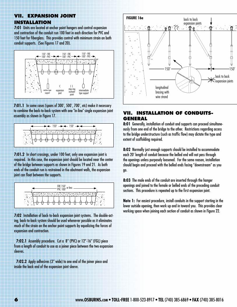
6:04.3 When ordering, supply the "X" and "Y" distances and angle of the fittings as shown in Figure 14.
FIGURE 14 - dimensions for determining length of braces
length o
f brace
struct
‘C’
horizonal distance ‘X’
vertic
al dis
tance
‘Y’
various styles of adjustable braces are available.
single bolt clampassembly forintermediate
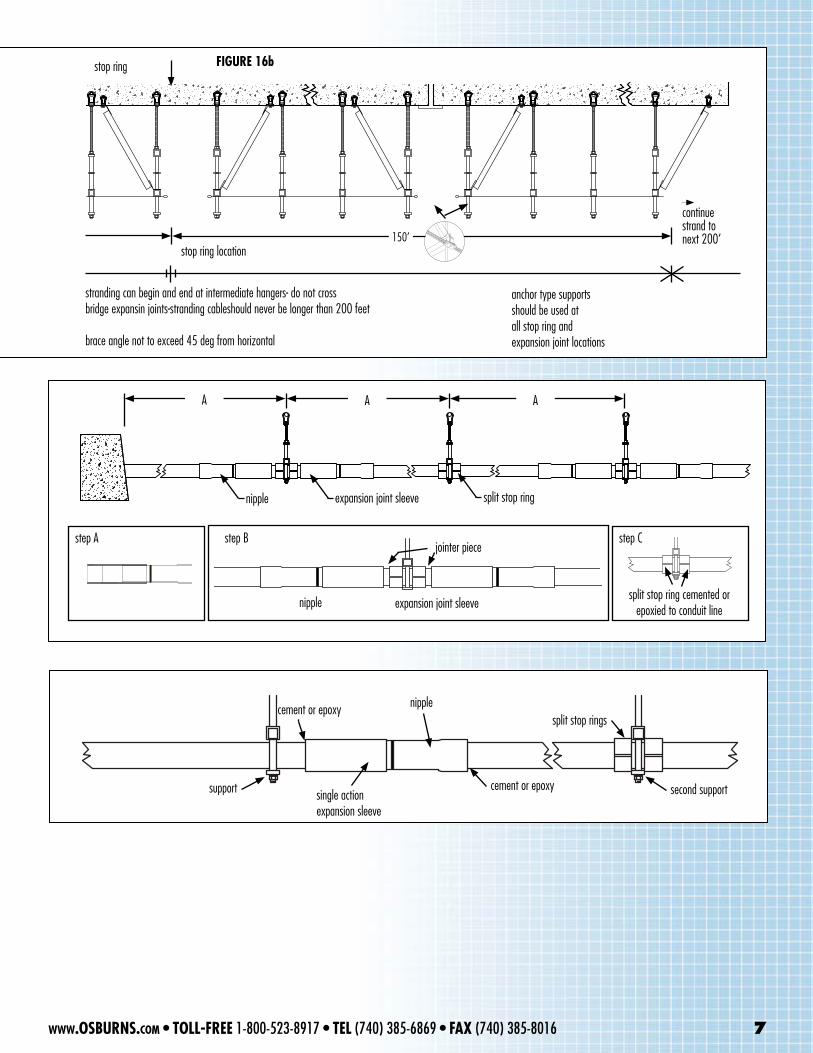
FIGURE 15 - guy clamps for longitudinal bracing
triple bolt clampassembly for strand termination
UB5904
UB5905
for installation of these clamps see figure 16
6:05 Longitudinal Bracing The purpose of longitudinal strand bracing is to enable intermediate supports to carry the loads developed primarily by expansion and contraction on the conduit.
6:05.1 Hangers are equipped with a 2” x 2” square tube with bolt holes for the attachment of the strands. The fittings shown in Figure 15 accom-modate the different strand sizes normally used on intermediate hangers. Note that a special “triple” clamp fitting is used for dead-ending strand.
6:05.2 The size and strength of the strand used will depend on the number of conduits plus the distance between angle-braced supports. A 3/16” strand (with an ultimate tensile strength of 2200 lbs) or a 3/8” strand (with an ultimate tensile strength of 8700 lbs) can be used depend-ing on the anticipated forces encountered. Guy clamps accommodate both of these strand sizes.
6:05.3 Longitudinal bracing should be terminated:(1) At both sides of bridge expansion joints.(2) At every stop ring location.(3) At a maximum strand length of 200’.
www.OSBURNS.com • TOLL-FREE 1-800-523-8917 • TEL (740) 385-6869 • FAX (740) 385-8016 5
7:01.2 In short crossings, under 100 feet, only one expansion joint is required. In this case, the expansion joint should be located near the center of the bridge between supports as shown in Figures 19 and 21. As both ends of the conduit run is restrained in the abutment walls, the expansion joint can float between the supports.
7:01.1 In some cases (spans of 300', 500', 700', etc) make it necessary to combine the back-to-back system with one "in-line" single expansion joint assembly as shown in Figure 17.
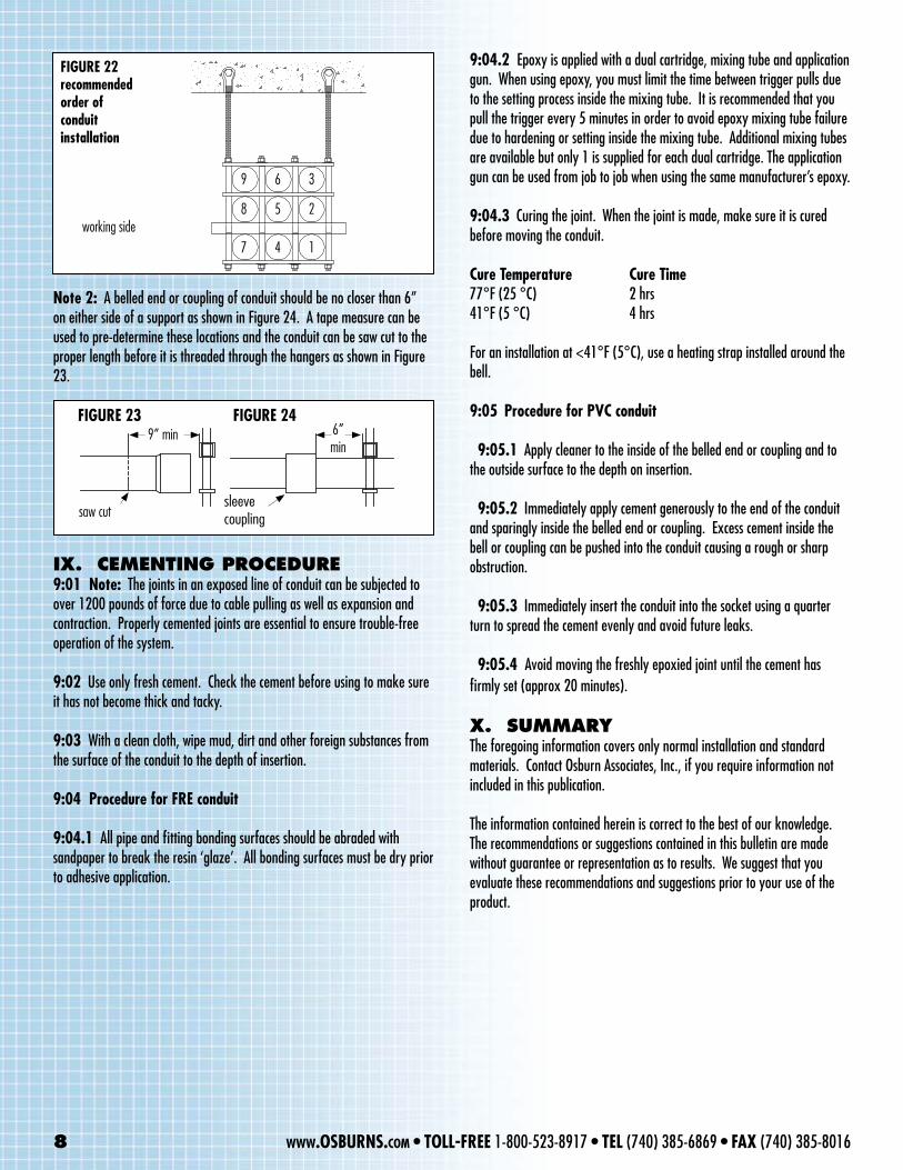
FIGURE 16a back to backexpansion joints
longitudinalbracing with wire strand
150’
back to backexpansion joints
VII. EXpANSION JOINt INStALLAtION7:01 Units are located at anchor point hangers and control expansion and contraction of the conduit run 100 feet in each direction for PVC and 150 feet for fiberglass. This provides control with minimum strain on both conduit supports. (See Figures 17 and 20).
7:02 Installation of back-to-back expansion joint systems. The double-act-ing, back-to-back system should be used whenever possible as it eliminates much of the strain on the anchor point supports by equalizing the forces of expansion and contraction.
7:02.1 Assembly procedure. Cut a 8” (PVC) or 12”-16” (FGL) piece from a length of conduit to use as a joiner piece between the two expansion sleeves.
7:02.2 Apply adhesives (3” wide) to one end of the joiner piece and inside the back end of the expansion joint sleeve.
VII. INStALLAtION Of CONDuItS-GENERAL8:01 Generally, installation of conduit and supports can proceed simultane-ously from one end of the bridge to the other. Restrictions regarding access to the bridge understructure (such as traffic flow) may dictate the type and extent of scaffolding required.
8:02 Normally just enough supports should be installed to accommodate each 20’ length of conduit because the belled end will not pass through the openings unless purposely loosened. For the same reason, installation should begin and proceed with the belled ends facing “downstream” as you go.
8:03 The male ends of the conduit are inserted through the hanger openings and joined to the female or belled ends of the preceding conduit sections. This procedure is repeated up to the first expansion joint.
Note 1: For easiest procedure, install conduits in the support starting in the lower outside opening, then work up and in toward you. This provides clear working space when joining each section of conduit as shown in Figure 22.
150’ - FRE100’ - PVC
anchor typesupport
expansionjoint
stop ringrestraint
pointintermediatetype support
150’ - FRE100’ - PVC
150’ - FRE100’ - PVC
150’ 150’
6 www.OSBURNS.com • TOLL-FREE 1-800-523-8917 • TEL (740) 385-6869 • FAX (740) 385-8016
150’
FRE 150’ PVC 100’ or less
nipple expansion joint sleeve split stop ring
A AA
cement or epoxy
step A
split stop ring cemented or epoxied to conduit line
step B step C
nipple expansion joint sleeve
jointer piece
stop ring
150’
back to backexpansion joints
stranding can begin and end at intermediate hangers- do not cross bridge expansin joints-stranding cableshould never be longer than 200 feet
brace angle not to exceed 45 deg from horizontal
anchor type supportsshould be used atall stop ring and expansion joint locations
150’
continuestrand tonext 200’
stop ring location
FIGURE 16b
nipple expansion joint sleeve split stop ring
cement or epoxy nipplesplit stop rings
second supportcement or epoxysingle actionexpansion sleeve
support
www.OSBURNS.com • TOLL-FREE 1-800-523-8917 • TEL (740) 385-6869 • FAX (740) 385-8016 7
Note 2: A belled end or coupling of conduit should be no closer than 6” on either side of a support as shown in Figure 24. A tape measure can be used to pre-determine these locations and the conduit can be saw cut to the proper length before it is threaded through the hangers as shown in Figure 23.
FIGURE 22recommendedorder ofconduitinstallation
working side7 4 1
8 5 2
9 6 3
FIGURE 23 FIGURE 249” min 6”
min
saw cutsleeve coupling
IX. CEmENtING pROCEDuRE9:01 Note: The joints in an exposed line of conduit can be subjected to over 1200 pounds of force due to cable pulling as well as expansion and contraction. Properly cemented joints are essential to ensure trouble-free operation of the system.
9:02 Use only fresh cement. Check the cement before using to make sure it has not become thick and tacky.
9:03 With a clean cloth, wipe mud, dirt and other foreign substances from the surface of the conduit to the depth of insertion.
9:04 Procedure for FRE conduit
9:04.1 All pipe and fitting bonding surfaces should be abraded with sandpaper to break the resin ‘glaze’. All bonding surfaces must be dry prior to adhesive application.
9:04.2 Epoxy is applied with a dual cartridge, mixing tube and application gun. When using epoxy, you must limit the time between trigger pulls due to the setting process inside the mixing tube. It is recommended that you pull the trigger every 5 minutes in order to avoid epoxy mixing tube failure due to hardening or setting inside the mixing tube. Additional mixing tubes are available but only 1 is supplied for each dual cartridge. The application gun can be used from job to job when using the same manufacturer’s epoxy.
9:04.3 Curing the joint. When the joint is made, make sure it is cured before moving the conduit.
Cure Temperature Cure Time77°F (25 °C) 2 hrs41°F (5 °C) 4 hrs
For an installation at <41°F (5°C), use a heating strap installed around the bell.
9:05 Procedure for PVC conduit
9:05.1 Apply cleaner to the inside of the belled end or coupling and to the outside surface to the depth on insertion.
9:05.2 Immediately apply cement generously to the end of the conduit and sparingly inside the belled end or coupling. Excess cement inside the bell or coupling can be pushed into the conduit causing a rough or sharp obstruction.
9:05.3 Immediately insert the conduit into the socket using a quarter turn to spread the cement evenly and avoid future leaks.
9:05.4 Avoid moving the freshly epoxied joint until the cement has firmly set (approx 20 minutes).
X. SummARYThe foregoing information covers only normal installation and standard materials. Contact Osburn Associates, Inc., if you require information not included in this publication.
The information contained herein is correct to the best of our knowledge. The recommendations or suggestions contained in this bulletin are made without guarantee or representation as to results. We suggest that you evaluate these recommendations and suggestions prior to your use of the product.
8 www.OSBURNS.com • TOLL-FREE 1-800-523-8917 • TEL (740) 385-6869 • FAX (740) 385-8016
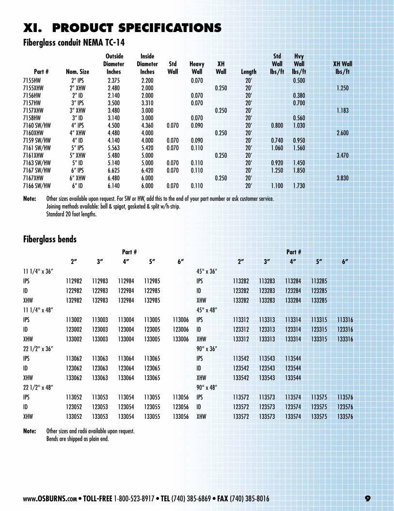
Part # Nom. Size
Outside Diameter
Inches
Inside Diameter
InchesStd Wall
Heavy Wall
XH Wall Length
Std Wall
lbs/ft
Hvy Wall
lbs/ftXH Wall lbs/ft
7155HW 2” IPS 2.375 2.200 0.070 20’ 0.5007155XHW 2” XHW 2.480 2.000 0.250 20’ 1.2507156HW 2” ID 2.140 2.000 0.070 20’ 0.3807157HW 3” IPS 3.500 3.310 0.070 20’ 0.7007157XHW 3” XHW 3.480 3.000 0.250 20’ 1.1837158HW 3” ID 3.140 3.000 0.070 20’ 0.5607160 SW/HW 4” IPS 4.500 4.360 0.070 0.090 20’ 0.800 1.0307160XHW 4” XHW 4.480 4.000 0.250 20’ 2.6007159 SW/HW 4” ID 4.140 4.000 0.070 0.090 20’ 0.740 0.9507161 SW/HW 5” IPS 5.563 5.420 0.070 0.110 20’ 1.060 1.5607161XHW 5” XHW 5.480 5.000 0.250 20’ 3.4707163 SW/HW 5” ID 5.140 5.000 0.070 0.110 20’ 0.920 1.4507167 SW/HW 6” IPS 6.625 6.420 0.070 0.110 20’ 1.250 1.8507167XHW 6” XHW 6.480 6.000 0.250 20’ 3.8307166 SW/HW 6” ID 6.140 6.000 0.070 0.110 20’ 1.100 1.730
XI. pRODuCt SpECIfICAtIONSFiberglass conduit NEMA TC-14
Fiberglass bends
Note: Other sizes available upon request. For SW or HW, add this to the end of your part number or ask customer service. Joining methods available: bell & spigot, gasketed & split w/h-strip. Standard 20 foot lengths.
Part # Part # 2” 3” 4” 5” 6” 2” 3” 4” 5” 6”
11 1/4° x 36” 45° x 36”IPS 112982 112983 112984 112985 IPS 113282 113283 113284 113285ID 122982 122983 122984 122985 ID 123282 123283 123284 123285XHW 132982 132983 132984 132985 XHW 133282 133283 133284 13328511 1/4° x 48” 45° x 48”IPS 113002 113003 113004 113005 113006 IPS 113312 113313 113314 113315 113316ID 123002 123003 123004 123005 123006 ID 123312 123313 123314 123315 123316XHW 133002 133003 133004 133005 133006 XHW 133312 133313 133314 133315 13331622 1/2° x 36” 90° x 36”IPS 113062 113063 113064 113065 IPS 113542 113543 113544ID 123062 123063 123064 123065 ID 123542 123543 123544XHW 133062 133063 133064 133065 XHW 133542 133543 13354422 1/2° x 48” 90° x 48”IPS 113052 113053 113054 113055 113056 IPS 113572 113573 113574 113575 113576ID 123052 123053 123054 123055 123056 ID 123572 123573 123574 123575 123576XHW 133052 133053 133054 133055 133056 XHW 133572 133573 133574 133575 133576
Note: Other sizes and radii available upon request. Bends are shipped as plain end.
www.OSBURNS.com • TOLL-FREE 1-800-523-8917 • TEL (740) 385-6869 • FAX (740) 385-8016 9
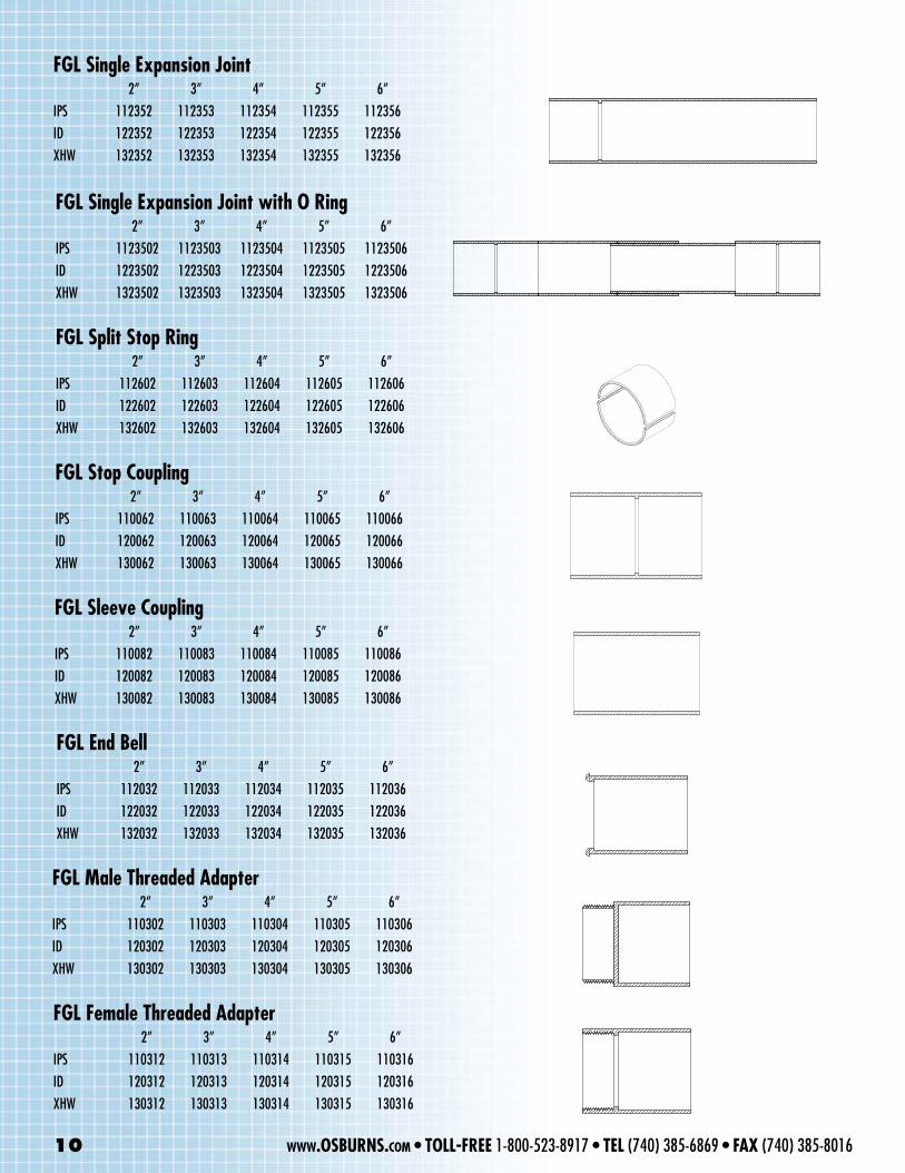
FGL Single Expansion Joint2” 3” 4” 5” 6”
IPS 112352 112353 112354 112355 112356ID 122352 122353 122354 122355 122356XHW 132352 132353 132354 132355 132356
FGL Single Expansion Joint with O Ring2” 3” 4” 5” 6”
IPS 1123502 1123503 1123504 1123505 1123506ID 1223502 1223503 1223504 1223505 1223506XHW 1323502 1323503 1323504 1323505 1323506
FGL Split Stop Ring2” 3” 4” 5” 6”
IPS 112602 112603 112604 112605 112606ID 122602 122603 122604 122605 122606XHW 132602 132603 132604 132605 132606
FGL Stop Coupling2” 3” 4” 5” 6”
IPS 110062 110063 110064 110065 110066ID 120062 120063 120064 120065 120066XHW 130062 130063 130064 130065 130066
FGL Sleeve Coupling2” 3” 4” 5” 6”
IPS 110082 110083 110084 110085 110086ID 120082 120083 120084 120085 120086XHW 130082 130083 130084 130085 130086
FGL End Bell2” 3” 4” 5” 6”
IPS 112032 112033 112034 112035 112036ID 122032 122033 122034 122035 122036XHW 132032 132033 132034 132035 132036
FGL Male Threaded Adapter2” 3” 4” 5” 6”
IPS 110302 110303 110304 110305 110306ID 120302 120303 120304 120305 120306XHW 130302 130303 130304 130305 130306
FGL Female Threaded Adapter2” 3” 4” 5” 6”
IPS 110312 110313 110314 110315 110316ID 120312 120313 120314 120315 120316XHW 130312 130313 130314 130315 130316
5°
10 www.OSBURNS.com • TOLL-FREE 1-800-523-8917 • TEL (740) 385-6869 • FAX (740) 385-8016
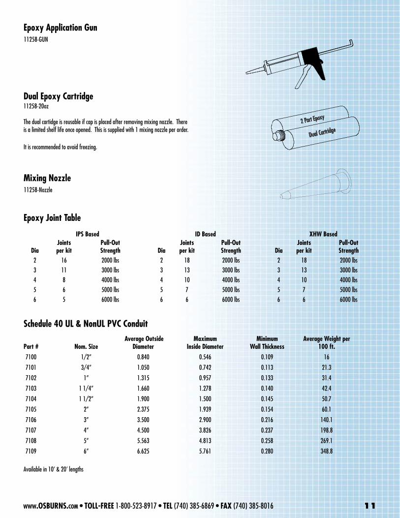
Epoxy Application Gun
Dual Epoxy Cartridge
Mixing Nozzle
Epoxy Joint Table
11258-GUN
11258-Nozzle
11258-20oz
The dual cartidge is reusable if cap is placed after removing mixing nozzle. There is a limited shelf life once opened. This is supplied with 1 mixing nozzle per order. It is recommended to avoid freezing.
IPS Based ID Based XHW Based
DiaJoints per kit
Pull-Out Strength Dia
Joints per kit
Pull-Out Strength Dia
Joints per kit
Pull-Out Strength
2 16 2000 lbs 2 18 2000 lbs 2 18 2000 lbs3 11 3000 lbs 3 13 3000 lbs 3 13 3000 lbs4 8 4000 lbs 4 10 4000 lbs 4 10 4000 lbs5 6 5000 lbs 5 7 5000 lbs 5 7 5000 lbs6 5 6000 lbs 6 6 6000 lbs 6 6 6000 lbs
Schedule 40 UL & NonUL PVC Conduit
Part # Nom. Size Average Outside
Diameter Maximum
Inside DiameterMinimum
Wall ThicknessAverage Weight per
100 ft.
7100 1/2” 0.840 0.546 0.109 16
7101 3/4” 1.050 0.742 0.113 21.3
7102 1” 1.315 0.957 0.133 31.4
7103 1 1/4” 1.660 1.278 0.140 42.4
7104 1 1/2” 1.900 1.500 0.145 50.7
7105 2” 2.375 1.939 0.154 60.1
7106 3” 3.500 2.900 0.216 140.1
7107 4” 4.500 3.826 0.237 198.8
7108 5” 5.563 4.813 0.258 269.1
7109 6” 6.625 5.761 0.280 348.8
Available in 10’ & 20’ lengths
www.OSBURNS.com • TOLL-FREE 1-800-523-8917 • TEL (740) 385-6869 • FAX (740) 385-8016 11
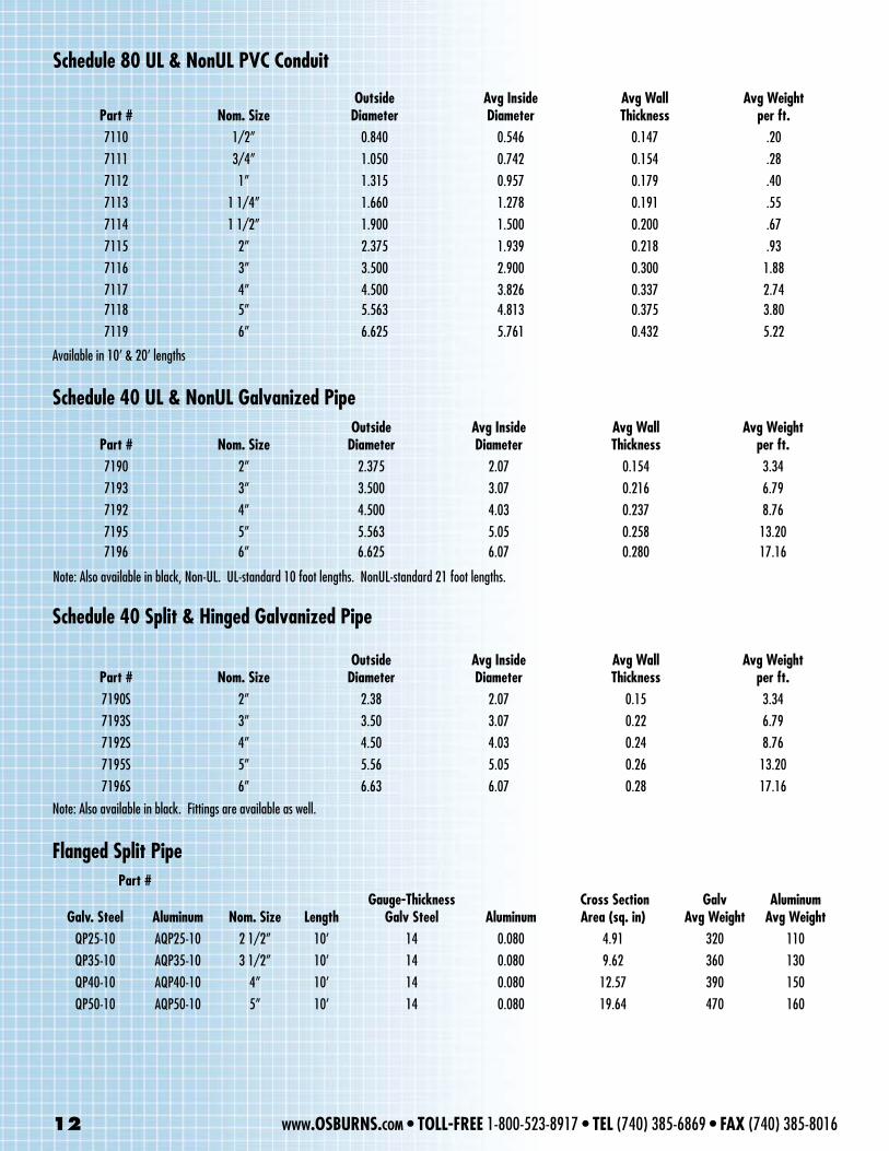
Schedule 80 UL & NonUL PVC Conduit
Part # Nom. SizeOutside
Diameter Avg Inside Diameter
Avg Wall Thickness
Avg Weightper ft.
7110 1/2” 0.840 0.546 0.147 .207111 3/4” 1.050 0.742 0.154 .287112 1” 1.315 0.957 0.179 .407113 1 1/4” 1.660 1.278 0.191 .557114 1 1/2” 1.900 1.500 0.200 .677115 2” 2.375 1.939 0.218 .937116 3” 3.500 2.900 0.300 1.887117 4” 4.500 3.826 0.337 2.747118 5” 5.563 4.813 0.375 3.807119 6” 6.625 5.761 0.432 5.22
Part # Nom. SizeOutside
Diameter Avg Inside Diameter
Avg WallThickness
Avg Weightper ft.
7190 2” 2.375 2.07 0.154 3.347193 3” 3.500 3.07 0.216 6.797192 4” 4.500 4.03 0.237 8.767195 5” 5.563 5.05 0.258 13.207196 6” 6.625 6.07 0.280 17.16
Schedule 40 UL & NonUL Galvanized Pipe
Schedule 40 Split & Hinged Galvanized Pipe
Note: Also available in black, Non-UL. UL-standard 10 foot lengths. NonUL-standard 21 foot lengths.
Part # Nom. SizeOutside
Diameter Avg Inside Diameter
Avg Wall Thickness
Avg Weight per ft.
7190S 2” 2.38 2.07 0.15 3.347193S 3” 3.50 3.07 0.22 6.797192S 4” 4.50 4.03 0.24 8.767195S 5” 5.56 5.05 0.26 13.207196S 6” 6.63 6.07 0.28 17.16
Note: Also available in black. Fittings are available as well.
Part #
Galv. Steel Aluminum Nom. Size LengthGauge-Thickness
Galv Steel Aluminum Cross Section Area (sq. in)
Galv Avg Weight
AluminumAvg Weight
QP25-10 AQP25-10 2 1/2” 10’ 14 0.080 4.91 320 110QP35-10 AQP35-10 3 1/2” 10’ 14 0.080 9.62 360 130QP40-10 AQP40-10 4” 10’ 14 0.080 12.57 390 150QP50-10 AQP50-10 5” 10’ 14 0.080 19.64 470 160
Flanged Split Pipe
Available in 10’ & 20’ lengths
12 www.OSBURNS.com • TOLL-FREE 1-800-523-8917 • TEL (740) 385-6869 • FAX (740) 385-8016
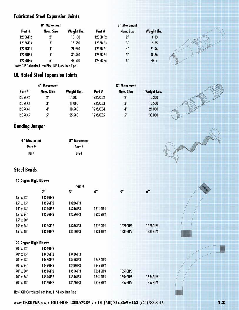
8” Movement 8” MovementPart # Nom. Size Weight Lbs. Part # Nom. Size Weight Lbs.
1235GIP2 2” 10.130 1235BIP2 2” 10.131235GIP3 3” 15.550 1235BIP3 3” 15.551235GIP4 4” 21.960 1235BIP4 4” 21.961235GIP5 5” 30.360 1235BIP5 5” 30.361235GIP6 6” 47.500 1235BIP6 6” 47.5
Fabricated Steel Expansion Joints
UL Rated Steel Expansion Joints
4” Movement 8” MovementPart # Nom. Size Weight Lbs. Part # Nom. Size Weight Lbs.
1235AX2 2” 7.000 1235AX82 2” 10.3001235AX3 3” 11.000 1235AX83 3” 15.5001235AX4 4” 18.500 1235AX84 4” 24.0001235AX5 5” 25.500 1235AX85 5” 33.000
Bonding Jumper
4” Movement 8” Movement
Part # Part #
BJ14 BJ24
Steel Bends
Note: GIP Galvanized Iron Pipe, BIP Black Iron Pipe
Note: GIP-Galvanized Iron Pipe, BIP-Black Iron Pipe
45 Degree Rigid Elbows Part #
2” 3” 4” 5” 6”45° x 12” 1321GIP245° x 15” 1322GIP2 1322GIP3 45° x 18” 1324GIP2 1324GIP3 1324GIP445° x 24” 1325GIP2 1325GIP3 1325GIP445° x 30”45° x 36” 1328GIP2 1328GIP3 1328GIP4 1328GIP5 1328GIP645° x 48” 1331GIP2 1331GIP3 1331GIP4 1331GIP5 1331GIP6
90 Degree Rigid Elbows 90° x 12” 1324GIP290° x 15” 1343GIP2 1343GIP3 90° x 18” 1345GIP2 1345GIP3 1345GIP490° x 24” 1348GIP2 1348GIP3 1348GIP490° x 30” 1351GIP2 1351GIP3 1351GIP4 1351GIP590° x 36” 1354GIP2 1354GIP3 1354GIP4 1354GIP5 1354GIP690° x 48” 1357GIP2 1357GIP3 1357GIP4 1357GIP5 1357GIP6
www.OSBURNS.com • TOLL-FREE 1-800-523-8917 • TEL (740) 385-6869 • FAX (740) 385-8016 13
14 www.OSBURNS.com • TOLL-FREE 1-800-523-8917 • TEL (740) 385-6869 • FAX (740) 385-8016
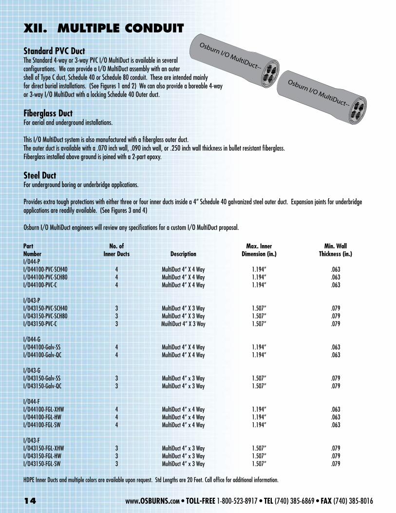
XII. muLtIpLE CONDuIt
Standard PVC Duct The Standard 4-way or 3-way PVC I/O MultiDuct is available in several configurations. We can provide a I/O MultiDuct assembly with an outer shell of Type C duct, Schedule 40 or Schedule 80 conduit. These are intended mainly for direct burial installations. (See Figures 1 and 2) We can also provide a boreable 4-way or 3-way I/O MultiDuct with a locking Schedule 40 Outer duct.
Fiberglass DuctFor aerial and underground installations.
This I/O MultiDuct system is also manufactured with a fiberglass outer duct. The outer duct is available with a .070 inch wall, .090 inch wall, or .250 inch wall thickness in bullet resistant fiberglass. Fiberglass installed above ground is joined with a 2-part epoxy.
Steel DuctFor underground boring or underbridge applications. Provides extra tough protections with either three or four inner ducts inside a 4” Schedule 40 galvanized steel outer duct. Expansion joints for underbridge applications are readily available. (See Figures 3 and 4) Osburn I/O MultiDuct engineers will review any specifications for a custom I/O MultiDuct proposal.
Osburn I/O MultiDuct--
Osburn I/O MultiDuct--
Part No. of Max. Inner Min. WallNumber Inner Ducts Description Dimension (in.) Thickness (in.)I/O44-PI/O44100-PVC-SCH40 4 MultiDuct 4” X 4 Way 1.194” .063I/O44100-PVC-SCH80 4 MultiDuct 4” X 4 Way 1.194” .063I/O44100-PVC-C 4 MultiDuct 4” X 4 Way 1.194” .063
I/O43-PI/O43150-PVC-SCH40 3 MultiDuct 4” X 3 Way 1.507” .079I/O43150-PVC-SCH80 3 MultiDuct 4” X 3 Way 1.507” .079I/O43150-PVC-C 3 MuiltiDuct 4” X 3 Way 1.507” .079
I/O44-GI/O44100-Galv-SS 4 MultiDuct 4” X 4 Way 1.194” .063I/O44100-Galv-QC 4 MultiDuct 4” X 4 Way 1.194” .063
I/O43-G I/O43150-Galv-SS 3 MultiDuct 4” x 3 Way 1.507” .079I/O43150-Galv-QC 3 MultiDuct 4” x 3 Way 1.507” .079
I/O44-FI/O44100-FGL-XHW 4 MultiDuct 4” x 4 Way 1.194” .063I/O44100-FGL-HW 4 MultiDuct 4” x 4 Way 1.194” .063I/O44100-FGL-SW 4 MultiDuct 4” x 4 Way 1.194” .063
I/O43-FI/O43150-FGL-XHW 3 MultiDuct 4” x 3 Way 1.507” .079I/O43150-FGL-HW 3 MultiDuct 4” x 3 Way 1.507” .079I/O43150-FGL-SW 3 MultiDuct 4” x 3 Way 1.507” .079
HDPE Inner Ducts and multiple colors are available upon request. Std Lengths are 20 Feet. Call office for additional information.
www.OSBURNS.com • TOLL-FREE 1-800-523-8917 • TEL (740) 385-6869 • FAX (740) 385-8016 15
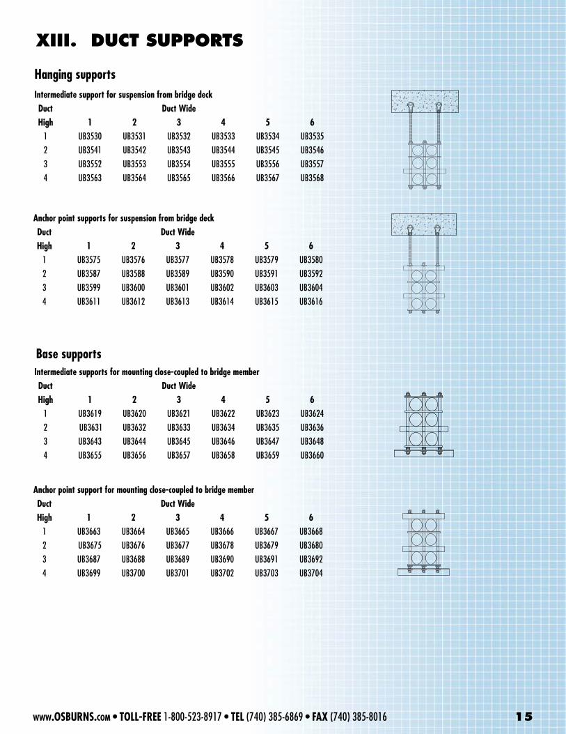
XIII. DuCt SuppORtS
Hanging supports
Intermediate support for suspension from bridge deck Duct Duct Wide High 1 2 3 4 5 6 1 UB3530 UB3531 UB3532 UB3533 UB3534 UB3535 2 UB3541 UB3542 UB3543 UB3544 UB3545 UB3546 3 UB3552 UB3553 UB3554 UB3555 UB3556 UB3557 4 UB3563 UB3564 UB3565 UB3566 UB3567 UB3568
Anchor point supports for suspension from bridge deck Duct Duct Wide High 1 2 3 4 5 6 1 UB3575 UB3576 UB3577 UB3578 UB3579 UB3580 2 UB3587 UB3588 UB3589 UB3590 UB3591 UB3592 3 UB3599 UB3600 UB3601 UB3602 UB3603 UB3604 4 UB3611 UB3612 UB3613 UB3614 UB3615 UB3616
Intermediate supports for mounting close-coupled to bridge member Duct Duct Wide High 1 2 3 4 5 6 1 UB3619 UB3620 UB3621 UB3622 UB3623 UB3624 2 UB3631 UB3632 UB3633 UB3634 UB3635 UB3636 3 UB3643 UB3644 UB3645 UB3646 UB3647 UB3648 4 UB3655 UB3656 UB3657 UB3658 UB3659 UB3660
Base supports
Anchor point support for mounting close-coupled to bridge member Duct Duct Wide High 1 2 3 4 5 6 1 UB3663 UB3664 UB3665 UB3666 UB3667 UB3668 2 UB3675 UB3676 UB3677 UB3678 UB3679 UB3680 3 UB3687 UB3688 UB3689 UB3690 UB3691 UB3692 4 UB3699 UB3700 UB3701 UB3702 UB3703 UB3704
16 www.OSBURNS.com • TOLL-FREE 1-800-523-8917 • TEL (740) 385-6869 • FAX (740) 385-8016
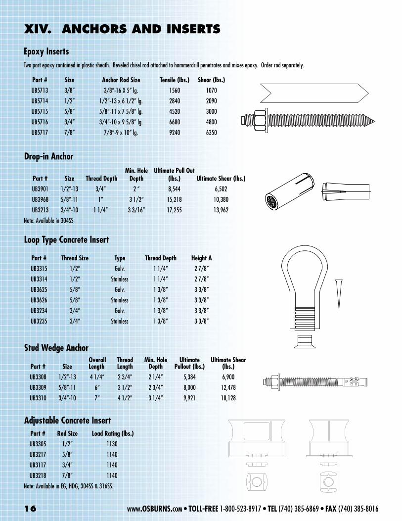
XIV. ANChORS AND INSERtS
Epoxy InsertsTwo part epoxy contained in plastic sheath. Beveled chisel rod attached to hammerdrill penetrates and mixes epoxy. Order rod separately.
Part # Size Anchor Rod Size Tensile (lbs.) Shear (lbs.)
UB5713 3/8” 3/8”-16 X 5” lg. 1560 1070
UB5714 1/2” 1/2”-13 x 6 1/2” lg. 2840 2090
UB5715 5/8” 5/8”-11 x 7 5/8” lg. 4520 3000
UB5716 3/4” 3/4”-10 x 9 5/8” lg. 6680 4800
UB5717 7/8” 7/8”-9 x 10” lg. 9240 6350
Drop-in Anchor
Part # Size Thread Depth Min. Hole
DepthUltimate Pull Out
(lbs.) Ultimate Shear (lbs.)
UB3901 1/2”-13 3/4” 2 ” 8,544 6,502
UB3968 5/8”-11 1” 3 1/2” 15,218 10,380
UB3213 3/4”-10 1 1/4” 3 3/16” 17,255 13,962
Note: Available in 304SS
Loop Type Concrete Insert
Part # Thread Size Type Thread Depth Height A
UB3315 1/2” Galv. 1 1/4” 2 7/8”
UB3314 1/2” Stainless 1 1/4” 2 7/8”
UB3625 5/8” Galv. 1 3/8” 3 3/8”
UB3626 5/8” Stainless 1 3/8” 3 3/8”
UB3234 3/4” Galv. 1 3/8” 3 3/8”
UB3235 3/4” Stainless 1 3/8” 3 3/8”
Stud Wedge Anchor
Part # Size Overall Length
Thread Length
Min. Hole Depth
Ultimate Pullout (lbs.)
Ultimate Shear (lbs.)
UB3308 1/2”-13 4 1/4” 2 3/4” 2 1/4” 5,384 6,900
UB3309 5/8”-11 6” 3 1/2” 2 3/4” 8,000 12,478
UB3310 3/4”-10 7” 4 1/2” 3 1/4” 9,921 18,128
Part # Rod Size Load Rating (lbs.)
UB3305 1/2” 1130
UB3217 5/8” 1140
UB3117 3/4” 1140
UB3218 7/8” 1140
Note: Available in EG, HDG, 304SS & 316SS.
Adjustable Concrete Insert
XV. hARDwARE
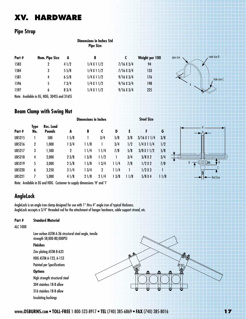
Pipe StrapDimensions in Inches Std
Pipe Size
Part # Nom. Pipe Size A B C Weight per 100
1583 2 4 1/2 1/4 X 1 1/2 7/16 X 3/4 94
1584 3 5 5/8 1/4 X 1 1/2 7/16 X 3/4 133
1581 4 6 5/8 1/4 X 1 1/2 9/16 X 3/4 176
1596 5 7 3/4 1/4 X 1 1/2 9/16 X 3/4 198
1597 6 8 3/4 1/4 X 1 1/2 9/16 X 3/4 225
Note: Available in EG, HDG, 304SS and 316SS
Steel Size
Part #Type No.
Rec. Load Pounds A B C D E F G
UB5215 1 500 1 5/8 1 3/4 5/8 3/8 3/16 X 1 1/4 3/8
UB5216 2 1,000 1 3/4 1 1/8 1 3/4 1/2 1/4 X 1 1/4 1/2
UB5217 3 1,500 2 1 1/4 1 1/4 7/8 5/8 3/8 X 1 1/2 5/8
UB5218 4 2,000 2 3/8 1 3/8 1 1/2 1 3/4 3/8 X 2 3/4
UB5219 5 3,000 2 5/8 1 5/8 1 3/4 1 1/4 7/8 1/2 X 2 7/8
UB5220 6 3,250 3 1/4 1 3/4 2 1 1/4 1 1/2 X 3 1
UB5221 7 5,000 4 1/8 2 1/8 2 1/4 1 3/8 1 1/8 5/8 X 4 1 1/8
Note: Available in EG and HDG. Customer to supply dimensions ‘H’ and ‘I’
Beam Clamp with Swing Nut
A
pipe size steel size B
hole size C
Dimensions in Inches
AngleLock is an angle iron clamp designed for use with 1” thru 4” angle iron of typical thickness.AngleLock acccepts a 3/4” threaded rod for the attachment of hanger hardware, cable support strand, etc.
AngleLock
Part # Standard Material
ALC 1000
Low carbon ASTM A-36 structural steel angle, tensile strength 58,000-80,000PSI
Finishes
Zinc plating ASTM B-633
HDG ASTM A-123, A-153
Painted per Specifications
Options
High strength structural steel
304 stainless 18-8 allow
316 stainless 18-8 allow
Insulating bushings
Rod Size
AB
C
HD
I
www.OSBURNS.com • TOLL-FREE 1-800-523-8917 • TEL (740) 385-6869 • FAX (740) 385-8016 17
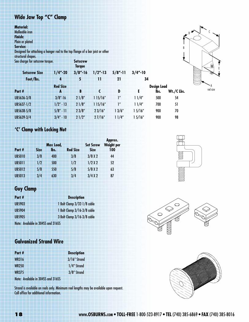
Wide Jaw Top “C” Clamp
Setscrew Torque
Setscrew Size 1/4”-20 3/8”-16 1/2”-13 5/8”-11 3/4”-10
Foot/lbs. 4 5 11 21 34
Part # A B C D EDesign Load
lbs. Wt./C Lbs.
UB5636-3/8 3/8”-16 2 1/8” 1 15/16” 1” 1 1/4” 500 54
UB5637-1/2 1/2” - 13 2 1/8” 1 15/16” 1” 1 1/4” 700 51
UB5638-5/8 5/8” - 11 2 3/8” 2 3/16” 1 3/6” 1 5/16” 900 70
UB5639-3/4 3/4” - 10 2 1/2” 2 7/16” 1 1/4” 1 5/16” 900 98
Rod Size
Material:Malleable ironFinish:Plain or platedService:Designed for attaching a hanger rod to the top flange of a bar joist or other structural shapes. See charge for setscrew torque.
Part # Description
UB5903 1 Bolt Clamp 3/32-1/8 cable
UB5904 1 Bolt Clamp 3/16-3/8 cable
UB5905 3 Bolt Clamp 3/16-3/8 cable
Note: Available in 304SS and 316SS
Guy Clamp
‘C’ Clamp with Locking Nut
Part # Size Max Load,
lbs. Rod SizeSet Screw
Size
Approx. Weight per
100
UB5010 3/8 400 3/8 3/8 X 2 44
UB5011 1/2 500 1/2 1/2 X 2 52
UB5012 5/8 550 5/8 5/8 X 2 63
UB5013 3/4 630 3/4 3/4 X 2 87
Galvanized Strand Wire
D C
B
E
A rod size
Part # Description
WR316 3/16” Strand
WR250 1/4” Strand
WR375 3/8” Strand
Note: Available in 304SS and 316SS
Strand is available on reels only. Minimum reel lengths may be available upon request. Call office for additional information.
18 www.OSBURNS.com • TOLL-FREE 1-800-523-8917 • TEL (740) 385-6869 • FAX (740) 385-8016
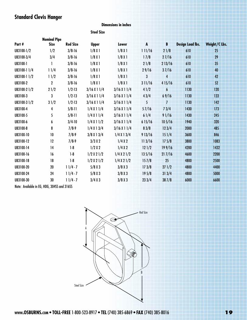
Steel Size
Part #Nominal Pipe
Size Rod Size Upper Lower A B Design Load lbs. Weight/C Lbs.
UB3100-1/2 1/2 3/8-16 1/8 X 1 1/8 X 1 1 11/16 2 1/8 610 25
UB3100-3/4 3/4 3/8-16 1/8 X 1 1/8 X 1 1 7/8 2 7/16 610 29
UB3100-1 1 3/8-16 1/8 X 1 1/8 X 1 2 1/8 2 13/16 610 35
UB3100-1 1/4 1 1/4 3/8-16 1/8 X 1 1/8 X 1 2 9/16 3 7/16 610 40
UB3100-1 1/2 1 1/2 3/8-16 1/8 X 1 1/8 X 1 3 4 610 42
UB3100-2 2 3/8-16 1/8 X 1 1/8 X 1 3 11/16 4 15/16 610 52
UB3100-2 1/2 2 1/2 1/2-13 3/16 X 1 1/4 3/16 X 1 1/4 4 1/2 6 1130 120
UB3100-3 3 1/2-13 3/16 X 1 1/4 3/16 X 1 1/4 4 3/4 6 9/16 1130 133
UB3100-3 1/2 3 1/2 1/2-13 3/16 X 1 1/4 3/16 X 1 1/4 5 7 1130 142
UB3100-4 4 5/8-11 1/4 X 1 1/4 3/16 X 1 1/4 5 7/16 7 3/4 1430 173
UB3100-5 5 5/8-11 1/4 X 1 1/4 3/16 X 1 1/4 6 1/4 9 1/16 1430 245
UB3100-6 6 3/4-10 1/4 X 1 1/2 3/16 X 1 1/4 6 15/16 10 5/16 1940 320
UB3100-8 8 7/8-9 1/4 X 1 3/4 3/16 X 1 1/4 8 3/8 12 3/4 2000 485
UB3100-10 10 7/8-9 3/8 X 1 3/4 1/4 X 1 3/4 9 13/16 15 1/4 3600 846
UB3100-12 12 7/8-9 3/3 X 2 1/4 X 2 11 3/16 17 5/8 3800 1083
UB3100-14 14 1-8 1/2 X 2 1/4 X 2 12 1/2 19 9/16 4200 1432
UB3100-16 16 1-8 1/2 X 2 1/2 1/4 X 2 1/2 13 5/16 21 7/16 4600 2200
UB3100-18 18 1-8 1/2 X 2 1/2 1/4 X 2 1/2 15 7/8 25 4800 2500
UB3100-20 20 1 1/4 - 7 5/8 X 3 3/8 X 3 17 3/8 27 1/2 4800 4400
UB3100-24 24 1 1/4 - 7 5/8 X 3 3/8 X 3 19 5/8 31 3/4 4800 5000
UB3100-30 30 1 1/4 - 7 3/4 X 3 3/8 X 3 23 3/4 38 7/8 6000 6600
Note: Available in EG, HDG, 304SS and 316SS
Standard Clevis HangerDimensions in inches
Rod Size
B
A
Steel Size
www.OSBURNS.com • TOLL-FREE 1-800-523-8917 • TEL (740) 385-6869 • FAX (740) 385-8016 19
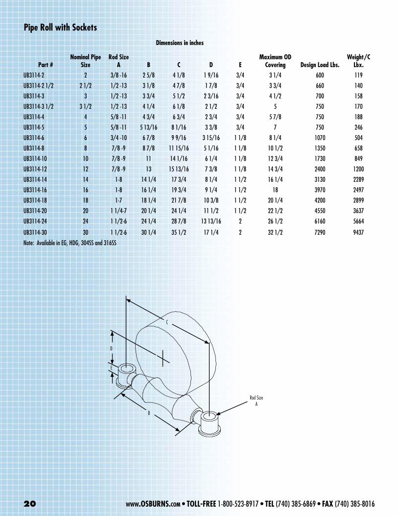
Pipe Roll with Sockets
Part #Nominal Pipe
SizeRod Size
A B C D EMaximum OD
Covering Design Load Lbs.Weight/C
Lbx.
UB3114-2 2 3/8 -16 2 5/8 4 1/8 1 9/16 3/4 3 1/4 600 119
UB3114-2 1/2 2 1/2 1/2 -13 3 1/8 4 7/8 1 7/8 3/4 3 3/4 660 140
UB3114-3 3 1/2 -13 3 3/4 5 1/2 2 3/16 3/4 4 1/2 700 158
UB3114-3 1/2 3 1/2 1/2 -13 4 1/4 6 1/8 2 1/2 3/4 5 750 170
UB3114-4 4 5/8 -11 4 3/4 6 3/4 2 3/4 3/4 5 7/8 750 188
UB3114-5 5 5/8 -11 5 13/16 8 1/16 3 3/8 3/4 7 750 246
UB3114-6 6 3/4 -10 6 7/8 9 9/16 3 15/16 1 1/8 8 1/4 1070 504
UB3114-8 8 7/8 -9 8 7/8 11 15/16 5 1/16 1 1/8 10 1/2 1350 658
UB3114-10 10 7/8 -9 11 14 1/16 6 1/4 1 1/8 12 3/4 1730 849
UB3114-12 12 7/8 -9 13 15 13/16 7 3/8 1 1/8 14 3/4 2400 1200
UB3114-14 14 1-8 14 1/4 17 3/4 8 1/4 1 1/2 16 1/4 3130 2289
UB3114-16 16 1-8 16 1/4 19 3/4 9 1/4 1 1/2 18 3970 2497
UB3114-18 18 1-7 18 1/4 21 7/8 10 3/8 1 1/2 20 1/4 4200 2899
UB3114-20 20 1 1/4-7 20 1/4 24 1/4 11 1/2 1 1/2 22 1/2 4550 3637
UB3114-24 24 1 1/2-6 24 1/4 28 7/8 13 13/16 2 26 1/2 6160 5664
UB3114-30 30 1 1/2-6 30 1/4 35 1/2 17 1/4 2 32 1/2 7290 9437
Note: Available in EG, HDG, 304SS and 316SS
Dimensions in inches
Rod Size A
B
C
D
E
20 www.OSBURNS.com • TOLL-FREE 1-800-523-8917 • TEL (740) 385-6869 • FAX (740) 385-8016
A
B
C
D
E
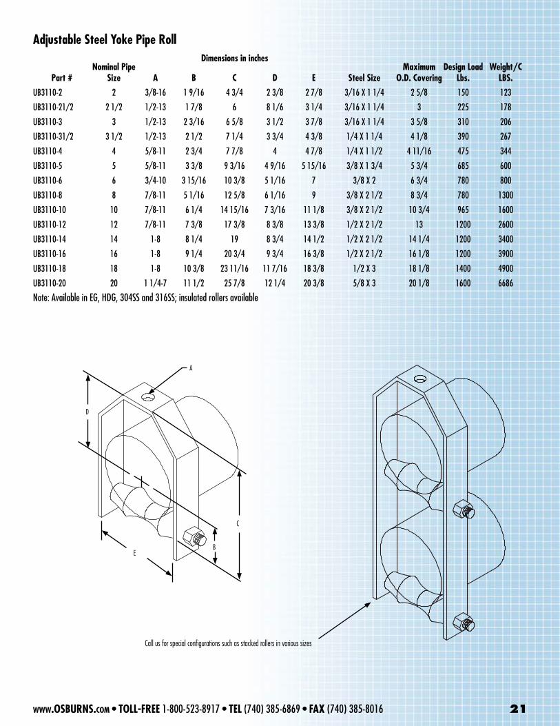
Adjustable Steel Yoke Pipe Roll
Call us for special configurations such as stacked rollers in various sizes
Part #Nominal Pipe
Size A B C D E Steel SizeMaximum
O.D. CoveringDesign Load
Lbs.Weight/C
LBS.
UB3110-2 2 3/8-16 1 9/16 4 3/4 2 3/8 2 7/8 3/16 X 1 1/4 2 5/8 150 123
UB3110-21/2 2 1/2 1/2-13 1 7/8 6 8 1/6 3 1/4 3/16 X 1 1/4 3 225 178
UB3110-3 3 1/2-13 2 3/16 6 5/8 3 1/2 3 7/8 3/16 X 1 1/4 3 5/8 310 206
UB3110-31/2 3 1/2 1/2-13 2 1/2 7 1/4 3 3/4 4 3/8 1/4 X 1 1/4 4 1/8 390 267
UB3110-4 4 5/8-11 2 3/4 7 7/8 4 4 7/8 1/4 X 1 1/2 4 11/16 475 344
UB3110-5 5 5/8-11 3 3/8 9 3/16 4 9/16 5 15/16 3/8 X 1 3/4 5 3/4 685 600
UB3110-6 6 3/4-10 3 15/16 10 3/8 5 1/16 7 3/8 X 2 6 3/4 780 800
UB3110-8 8 7/8-11 5 1/16 12 5/8 6 1/16 9 3/8 X 2 1/2 8 3/4 780 1300
UB3110-10 10 7/8-11 6 1/4 14 15/16 7 3/16 11 1/8 3/8 X 2 1/2 10 3/4 965 1600
UB3110-12 12 7/8-11 7 3/8 17 3/8 8 3/8 13 3/8 1/2 X 2 1/2 13 1200 2600
UB3110-14 14 1-8 8 1/4 19 8 3/4 14 1/2 1/2 X 2 1/2 14 1/4 1200 3400
UB3110-16 16 1-8 9 1/4 20 3/4 9 3/4 16 3/8 1/2 X 2 1/2 16 1/8 1200 3900
UB3110-18 18 1-8 10 3/8 23 11/16 11 7/16 18 3/8 1/2 X 3 18 1/8 1400 4900
UB3110-20 20 1 1/4-7 11 1/2 25 7/8 12 1/4 20 3/8 5/8 X 3 20 1/8 1600 6686
Note: Available in EG, HDG, 304SS and 316SS; insulated rollers available
Dimensions in inches
www.OSBURNS.com • TOLL-FREE 1-800-523-8917 • TEL (740) 385-6869 • FAX (740) 385-8016 21
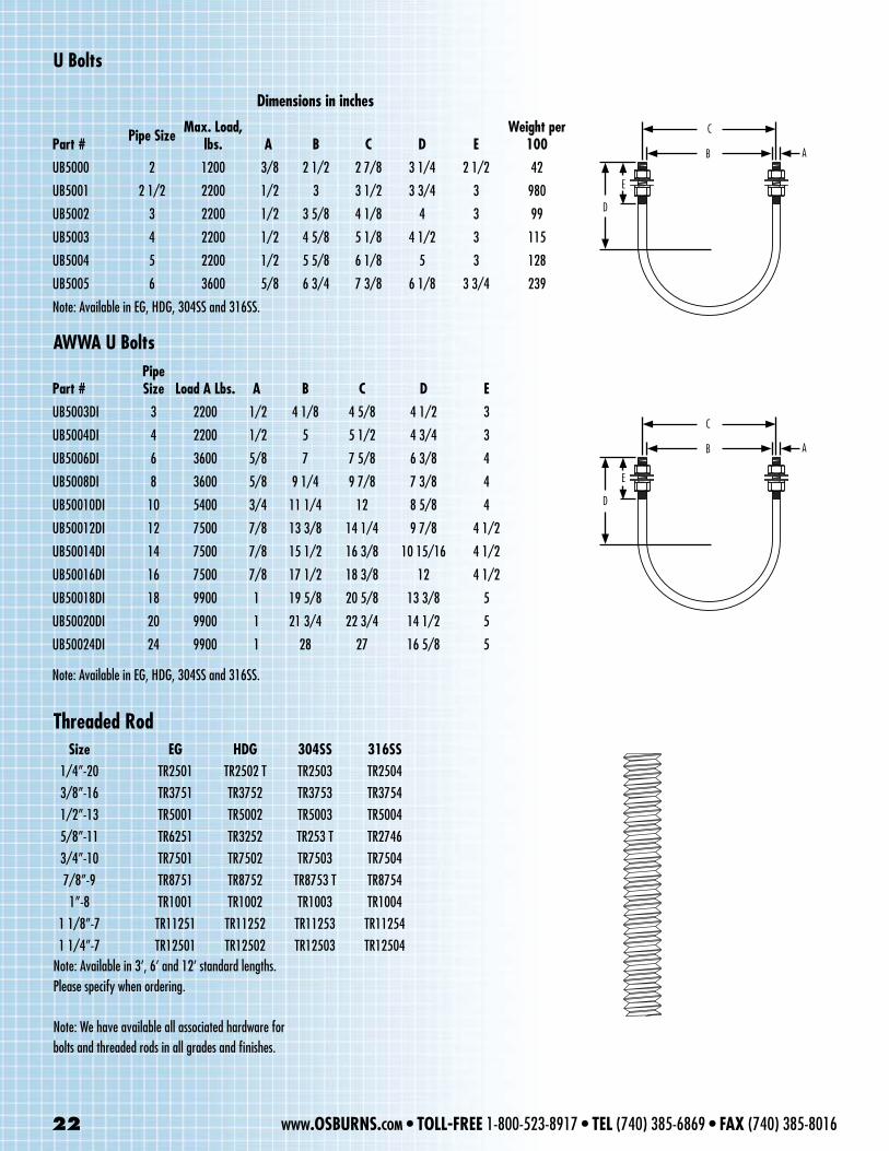
Part # Pipe Size Max. Load, lbs. A B C D E
Weight per 100
UB5000 2 1200 3/8 2 1/2 2 7/8 3 1/4 2 1/2 42
UB5001 2 1/2 2200 1/2 3 3 1/2 3 3/4 3 980
UB5002 3 2200 1/2 3 5/8 4 1/8 4 3 99
UB5003 4 2200 1/2 4 5/8 5 1/8 4 1/2 3 115
UB5004 5 2200 1/2 5 5/8 6 1/8 5 3 128
UB5005 6 3600 5/8 6 3/4 7 3/8 6 1/8 3 3/4 239
Note: Available in EG, HDG, 304SS and 316SS.
U Bolts
Dimensions in inches
AB
C
D
E
AB
C
D
E
AWWA U Bolts
Threaded Rod
Part #Pipe Size Load A Lbs. A B C D E
UB5003DI 3 2200 1/2 4 1/8 4 5/8 4 1/2 3
UB5004DI 4 2200 1/2 5 5 1/2 4 3/4 3
UB5006DI 6 3600 5/8 7 7 5/8 6 3/8 4
UB5008DI 8 3600 5/8 9 1/4 9 7/8 7 3/8 4
UB50010DI 10 5400 3/4 11 1/4 12 8 5/8 4
UB50012DI 12 7500 7/8 13 3/8 14 1/4 9 7/8 4 1/2
UB50014DI 14 7500 7/8 15 1/2 16 3/8 10 15/16 4 1/2
UB50016DI 16 7500 7/8 17 1/2 18 3/8 12 4 1/2
UB50018DI 18 9900 1 19 5/8 20 5/8 13 3/8 5
UB50020DI 20 9900 1 21 3/4 22 3/4 14 1/2 5
UB50024DI 24 9900 1 28 27 16 5/8 5
Note: Available in EG, HDG, 304SS and 316SS.
22 www.OSBURNS.com • TOLL-FREE 1-800-523-8917 • TEL (740) 385-6869 • FAX (740) 385-8016
Size EG HDG 304SS 316SS 1/4”-20 TR2501 TR2502 T TR2503 TR2504 3/8”-16 TR3751 TR3752 TR3753 TR3754 1/2”-13 TR5001 TR5002 TR5003 TR5004 5/8”-11 TR6251 TR3252 TR253 T TR2746 3/4”-10 TR7501 TR7502 TR7503 TR7504 7/8”-9 TR8751 TR8752 TR8753 T TR8754 1”-8 TR1001 TR1002 TR1003 TR1004 1 1/8”-7 TR11251 TR11252 TR11253 TR11254 1 1/4”-7 TR12501 TR12502 TR12503 TR12504Note: Available in 3’, 6’ and 12’ standard lengths.Please specify when ordering.
Note: We have available all associated hardware forbolts and threaded rods in all grades and finishes.
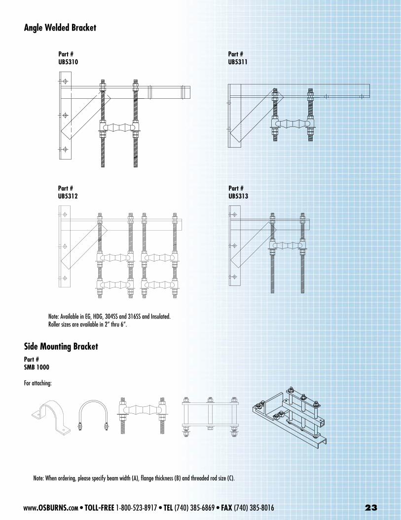
Angle Welded Bracket
Part #UB5310
Part #UB5311
Part #UB5312
Part #UB5313
Note: Available in EG, HDG, 304SS and 316SS and Insulated.Roller sizes are available in 2” thru 6”.
Side Mounting Bracket
Note: When ordering, please specify beam width (A), flange thickness (B) and threaded rod size (C).
Part #SMB 1000
For attaching:
www.OSBURNS.com • TOLL-FREE 1-800-523-8917 • TEL (740) 385-6869 • FAX (740) 385-8016 23
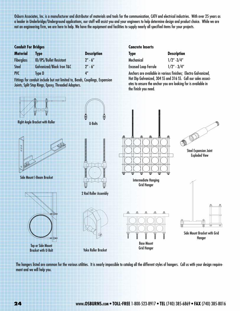
Concrete InsertsType DescriptionMechanical 1/2” -3/4”Encased Loop Ferrule 1/2” - 3/4”Anchors are available in various finishes; Electro Galvanized, Hot Dip Galvanized, 304 SS and 316 SS. Call our sales associ-ates to ensure the anchor you are looking for is available in the finish you need.
Right Angle Bracket with Roller
Steel Expansion Joint Exploded View
Side Mount I-Beam Bracket
Yoke Roller BracketTop or Side Mount
Bracket with U-Bolt
U-Bolts
Side Mount Bracket with Grid Hanger
2 Rod Roller Assembly
Intermediate Hanging Grid Hanger
Base Mount Grid Hanger
Osburn Associates, Inc. is a manufacturer and distributor of materials and tools for the communication, CATV and electrical industries. With over 25 years as a leader in Underbridge/Underground applications, our staff will assist you and your engineers to help determine design and product choice. While we are not an engineering firm, we are here to help. We have the equipment and facilities to supply nearly all specified items for your projects.
The hangers listed are common for the various utilities. It is nearly impossible to catalog all the different styles of hangers. Call us with your design require-ment and we will help you.
Conduit For BridgesMaterial Type DescriptionFiberglass ID/IPS/Bullet Resistant 2” - 6”Steel Galvanized/Black Iron T&C 2” - 6”PVC Type D 4” Fittings for conduit include but not limited to, Bends, Couplings, Expansion Joints, Split Stop Rings, Epoxy, Threaded Adapters.
24 www.OSBURNS.com • TOLL-FREE 1-800-523-8917 • TEL (740) 385-6869 • FAX (740) 385-8016

Poly-Dome™ Markers
Warning Tape
Barricades Type I, II & III
Traffic ConesStandard or Trimline
Reflective Collar or No Collar Height 6” thru 36”
Weight 1/4# thru 12#
Plastic Drums & Bases
Roll Up Signs& Stands
Line Markers
Reflective Shirts & Safety Vests
Osburn’s is a full line manufacturer of other products used in Underground Utility Construction from Outside Plant products for the Telecommunications, Electrical, CATV , Wind farm Applications, to pipe and products for GeoThermal, Water and Sewer applications.
We have all the necessary facilities and equipment to get your project completed in a timely manner.
Be sure to visit our webstore located at www.OSBuRNS.com
XVI. wORKZONE / SAfEtY
Your Custom Design
Here
Your Custom Design
Here
www.OSBURNS.com • TOLL-FREE 1-800-523-8917 • TEL (740) 385-6869 • FAX (740) 385-8016 25

Logan, OHTEL: 1-800-523-8917 • Fax: 1-740-385-8016
Osburn Associates’ complete steel fabrication and machine shop is ready to provide your custom items
as well as those shown on the preceding pages.
Important Notice to Purchaser:
All statements, technical information and recommendations contained herein are based on information we beleive to be reliable, but the accurace or completeness thereof is not guaranteed, and the folowing is made in lieu of all warranties, expressed or Implied. Osburn Associates, Inc.’s
only obligations shall be to replace any items that prove to be defective within one year after shipment to the original purchaser. Neither seller or manufacturer shall be liable for injury, loss or damage, direct or consequential, arising out of the use of this product. Before using, user shall
determine the suitablility of the product for his intended use, and user assumes all risk and liability whatsoever in connection therewith. No statement or recommendation not contained herein shall have any force or effect unless in an agreement, signed by officers of
Osburn Associates, Inc.
Other products available fromOsburn Associates, Inc.
PVC Telephone Conduit and Fittings • TetraDuct® • Fiberglass Conduit • Steel Conduit • Bridge Hangers and Accerssories • Schedule 40 and 80 Conduit • Split Duct • Corrugated and Smooth Wall Polyethylene Duct Linrer • Ropes • Pulling Tapes • Duct Liner Accessories • Terminators
Fish Tape • Duct Rods • Warning Tape • Cable ID Tags • Pole Risers • Line Missiles • Cable Lubricants and Accessories • Pulling Eyes and Harnesses